stereo tuner t-405x washbowl, kitchen sink, laundry tub, in a wet basement, or near a swimming pool,...
TRANSCRIPT

English
ACCUCLOCK
T-405X
FM STEREO / AM TUNER
MEMORYTIMERBAND CLEAR
AUTO/MONO
STANDBY/ON
TUNING
PRESET
CHARACTERDISPLAY
T-405X
FM STEREO TUNER
MEMORYTIMER CLEAR
AUTO/MONO
STANDBY/ON
ACCUCLOCK
TUNING
PRESET
CHARACTERDISPLAY
Instruction Manual
Stereo Tuner
T-405X Befo
re u
sing
Co
nn
ectio
ns
Op
era
tion
Oth
er In
form
atio
n

2
Thank you for purchasing ...Before using
Main Features
• High-Quality Separate Component• Preset Memory for Up to 30 Broadcast Stations• Auto Preset Memory Function• Weekly Program Timer
Thank you for purchasing the ONKYO T-405X Tuner.Please read this manual thoroughly before making any connection or turning on the power.Follow these instructions to obtain optimum performance and maximum listening enjoyment fromyour new Tuner. Please retain this manual for future reference.
Important Safeguards1. Read Instructions – All the safety and
operating instructions should be read beforethe appliance is operated.
2. Retain Instructions – The safety andoperating instructions should be retained forfuture reference.
3. Heed Warnings – All warnings on theappliance and in the operating instructionsshould be adhered to.
4. Follow Instructions – All operating and useinstructions should be followed.
5. Water and Moisture – The appliance shouldnot be used near water – for example, near abathtub, washbowl, kitchen sink, laundry tub,in a wet basement, or near a swimming pool,and the like.
6. Carts and Stands – The appliance should beused only with a cart or stand that isrecommended by the manufacturer.
6A. An appliance and cartcombination should bemoved with care. Quickstops, excessive force, anduneven surfaces may causethe appliance and cartcombination to overturn.
PORTABLE CART WARNING
S3125A
WARNING:TO REDUCE THE RISK OF FIRE OR ELECTRIC SHOCK, DO NOT EXPOSE THIS APPLIANCE TO RAIN OR MOISTURE.
CAUTION:TO REDUCE THE RISK OF ELECTRIC SHOCK, DO NOT REMOVE COVER (OR BACK). NO USER-SERVICEABLE PARTS INSIDE. REFER SERVICING TO QUALIFIED SERVICE PERSONNEL.
The lightning flash with arrowhead symbol, within an equilateral triangle, is intended to alert the user to the presence of uninsulated “dangerous voltage” within the product’s enclosure that may be of sufficient magnitude to constitute a risk of electric shock to persons.
The exclamation point within an equilateral triangle is intended to alert the user to the presence of important operating and maintenance (servicing) instructions in the literature accompanying the appliance.
WARNINGRISK OF ELECTRIC SHOCK
DO NOT OPENRISQUE DE CHOC ELECTRIQUE
NE PAS OUVRIR
AVIS
3
Befo
re U
sing
Co
nn
ectio
ns
Oth
er In
form
atio
nO
pera
tion
Important Safeguards
7. Wall or Ceiling Mounting – The applianceshould be mounted to a wall or ceiling onlyas recommended by the manufacturer.
8. Ventilation – The appliance should besituated so that its location or position doesnot interfere with its proper ventilation. Forexample, the appliance should not be situatedon a bed, sofa, rug, or similar surface thatmay block the ventilation openings; or ifplaced in a built-in installation, such as abookcase or cabinet that may impede the flowof air through the ventilation openings, thereshould be free space of at least 5 cm (2 in.)and an opening behind the appliance.
9. Heat – The appliance should be situated awayfrom heat sources such as radiators, heatregisters, stoves, or other appliances (includingamplifiers) that produce heat.
10. Power Sources – The appliance should beconnected to a power supply only of the typedescribed in the operating instructions or asmarked on the appliance.
11. Polarization – If the appliance is providedwith a polarized plug having one blade widerthan the other, please read the followinginformation: The polarization of the plug is asafety feature. The polarized plug will only fitthe outlet one way. If the plug does not fitfully into the outlet, try reversing it. If there isstill trouble, the user should seek the servicesof a qual i f ied electr ic ian. Under nocircumstances should the user attempt todefeat the polarization of the plug.
12. Power-Cord Protection – Power-supplycords should be routed so that they are notlikely to be walked on or pinched by itemsplaced upon or against them, especially nearplugs, convenience receptacles, and the pointwhere they exit from the appliance.
13. Cleaning – The appliance should be cleanedonly as recommended by the manufacturer.
14. Power Lines – An outdoor antenna shouldbe located away from power lines.
15. Nonuse Periods – The power cord of theappliance should be unplugged from the outletwhen left unused for a long period of time.
16. Object and Liquid Entry – Care should betaken so that objects do not fall and liquidsare not spilled into the enclosure throughopenings.
17. Damage Requiring Service – The applianceshould be serviced by qualified servicepersonnel when:
A. The power-supply cord or the plug hasbeen damaged; or
B. Objects have fallen, or liquid has beenspilled into the appliance; or
C. The appliance has been exposed to rain;or
D. The appliance does not appear to operatenormally or exhibits a marked change inperformance; or
E. The appliance has been dropped, or theenclosure damaged.
18. Servicing – The user should not attempt toservice the appliance beyond that describedin the operating instructions. All otherservicing should be referred to qualifiedservice personnel.
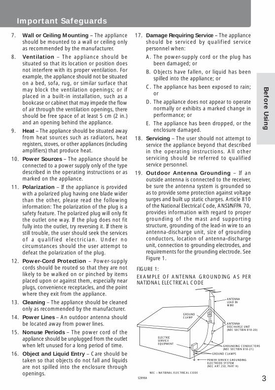
19. Outdoor Antenna Grounding – If anoutside antenna is connected to the receiver,be sure the antenna system is grounded soas to provide some protection against voltagesurges and built up static charges. Article 810of the National Electrical Code, ANSI/NFPA 70,provides information with regard to propergrounding of the mast and supportingstructure, grounding of the lead-in wire to anantenna-discharge unit, size of groundingconductors, location of antenna-dischargeunit, connection to grounding electrodes, andrequirements for the grounding electrode. SeeFigure 1.
FIGURE 1:
EXAMPLE OF ANTENNA GROUNDING AS PERNATIONAL ELECTRICAL CODE
ANTENNADISCHARGE UNIT(NEC SECTION 810-20)
GROUNDING CONDUCTORS(NEC SECTION 810-21)
GROUND CLAMPS
POWER SERVICE GROUNDINGELECTRODE SYSTEM(NEC ART 250, PART H)
NEC – NATIONAL ELECTRICAL CODE
ELECTRICSERVICEEQUIPMENT
GROUNDCLAMP
ANTENNALEAD INWIRE
S2898A

4
Precautions1. Warranty ClaimYou can find the serial number on the rear panel ofthis unit. In case of warranty claim, please report thisnumber.2. CareFrom time to time you should wipe the front andrear panels and the cabinet with a soft cloth. Forheavier dirt, dampen a soft cloth in a weak solutionof mild detergent and water, wring it out dry, andwipe off the dirt. Following this, dry immediately witha clean cloth. Do not use rough material, thinners,alcohol or other chemical solvents or cloths sincethese could damage the finish or remove the panellettering.3. PowerWARNINGBEFORE PLUGGING IN THE UNIT FOR THE FIRST TIME,READ THE FOLLOWING SECTION CAREFULLY.
The voltage of the available power supply differsaccording to country or region. Be sure that thepower supply voltage of the area where this unit willbe used meets the required voltage (e.g., AC 230 V,50 Hz or AC 120 V, 60 Hz) written on the rear panel.Setting the STANDBY button to standby does notshut off the power completely. So the power cordshould be removed from the AC outlet when theunit is not used for a prolonged time.
For British modelReplacement and mounting of an AC plug on thepower supply cord of this unit should be performedonly by qualified service personnel.IMPORTANTThe wires in the mains lead are coloured inaccordance with the following code:
Blue : NeutralBrown : Live
As the colours of the wires in the mains lead of thisapparatus may not correspond with the colouredmarkings identifying the terminals in your plug,proceed as follows:The wire which is coloured blue must be connectedto the terminal which is marked with the letter N orcoloured black.The wire which is coloured brown must beconnected to the terminal which is marked with theletter L or coloured red.IMPORTANTA 5 amp fuse is fitted in this plug. Should the fuseneed to be replaced, please ensure that thereplacement fuse has a rating of 5 amps and that itis approved by ASTA or BSI to BS1362. Check for theASTA mark or the BSI mark on the body of the fuse.IF THE FITTED MOULDED PLUG IS UNSUITABLE FORTHE SOCKET OUTLET IN YOUR HOME THEN THEFUSE SHOULD BE REMOVED AND THE PLUG CUTOFF AND DISPOSED OF SAFELY. THERE IS A DANGEROF SEVERE ELECTRICAL SHOCK IF THE CUT OFFPLUG IS INSERTED INTO ANY 13 AMP SOCKET.If in any doubt, please consult a qualified electrician.
For U.S. modelNote to CATV system installer:This reminder is provided to call the CATV systeminstaller’s attention to Article 820-40 of the NEC,ANSI/NFPA 70, which provides guidelines for propergrounding and, in particular, specifies that the cableground shall be connected to the grounding systemof the building, as close to the point of cable entryas practical.
FCC Information for UserCAUTION:The user changes or modifications not expresslyapproved by the party responsible for compliancecould void the user’s authority to operate theequipment.
NOTE:This equipment has been tested and found to complywith the limits for a Class B digital device, pursuantto Part 15 of the FCC Rules. These limits are designedto provide reasonable protection against harmfulinterference in a residential installation. Thisequipment generates, uses and can radiate radiofrequency energy and, if not installed and used inaccordance with the instructions, may cause harmfulinterference to radio communications. However,there is no guarantee that interference will not occurin a particular installation. If this equipment doescause harmful interference to radio or televisionreception, which can be determined by turning theequipment off and on, the user is encouraged to tryto correct the interference by one or more of thefollowing measures:• Reorient or relocate the receiving antenna.• Increase the separation between the equipment
and receiver.• Connect the equipment into an outlet on a circuit
different from that to which the receiver isconnected.
• Consult the dealer or an experienced radio/TVtechnician for help.
For Canadian modelFor models having a power cord with a polarizedplug:CAUTION: TO PREVENT ELECTRIC SHOCK, MATCHWIDE BLADE OF PLUG TO WIDE SLOT, FULLY INSERT.
Modele pour les CanadienSur les modèles dont la fiche est polarisée:ATTENTION: POUR ÉVITER LES CHOCS ÉLECTRIQUES,INTRODUIRE LA LAME LA PLUS LARGE DE LA FICHEDANS LA BORNE CORRESPONDANTE DE LA PRISEET POUSSER JUSQU’AU FOND.

5
Table of contentsB
efo
re U
sing
Supplied accessoriesCheck that the following accessories are supplied with this unit.
Audio connection cable × 1 remote control cable × 1 FM indoor antenna × 1(not available on the U.S. and Cnadian models)
AM loop antenna × 1(only available on the U.S. and Canadian models)
T-shaped FM indoor antenna × 1(only available on the U.S. and Canadian models)
ConnectionsConnecting to the ONKYO Separate Collection Series Components ................ 6Connecting to other components ................................................................... 8Antenna connections .................................................................................... 10
OperationSetting the Clock .......................................................................................... 12Receiving stations ......................................................................................... 16Naming a preset station ................................................................................ 19Receiving RDS (European models only) .......................................................... 22Using the timer ............................................................................................. 23
Other InformationTroubleshooting ............................................................................................ 30Index to parts and controls ............................................................................ 31Specifications ................................................................................................ 32
Declaration of Conformity
We, ONKYO EUROPEELECTRONICS GmbHINDUSTRIESTRASSE 2082110 GERMERING,GERMANY
GERMERING, GERMANY
ONKYO EUROPE ELECTRONICS GmbH
K.OTSU
declare in own responsibility, that the ONKYO product describedin this instruction manual is in compliance with the corresponding technical standards such as EN60065, EN55013, EN55020 and EN61000-3-2, -3-3 (or EN60555-2, -3)
Memory PreservationThis unit does not require memory preservation batteries.A built-in memory power back-up system preserves thecontents of the memory during power failures and evenwhen the unit is unplugged. The unit must be pluggedin order to charge the back-up system.The memory preservation period after the unit has beenunplugged varies depending on climate and placementof the unit. On the average, memory contents areprotected over a period of a few weeks after the lasttime the unit has been unplugged. This period is shorterwhen the unit is exposed to a highly humid climate.
6
Connecting to the ONKYO Separate Collection Series Components
This section introduces you to the other Separate Collection Series system components and theirconvenient system functions, followed by instruction on how to connect the system.
The following Separate Collection Series components are available:• A-905X ....... Integrated Stereo Amplifier• C-705X ....... Compact Disc (CD) Player (Not available in U.S. and Canada)• C-707CH .... Compact Disc (CD) Changer (Only available in U.S. and Canada)• K-505X ....... Stereo Cassette Tape Deck• MD-105X ... Minidisc (MD) Recorder (Not available in U.S. and Canada)
Note that the available components may vary according to the area.
Combining the T-405X Stereo tuner with the above system components enables you to operate thefollowing convenient functions:
• Auto Power On– You can turn on the power to the amplifier by pressing the STANDBY/ON button on one of the
system components. (The amplifier’s POWER switch must be set to ON.)– When the amplifier's POWER switch is set to ON, you can turn on the power to all the system
components simultaneously by pressing the STANDBY/ON button on the amplifier.Afterwards, you can turn off the power to the individual components that are not in use.
• Direct ChangePress the following button on the component you want to operate. The amplifier will automaticallyselect the input from the corresponding component:– The play button on the CD player (or changer), MD recorder, or stereo cassette tape deck; or– The PRESET √/® buttons on the tuner.
• Remote Control OperationYou can operate all the system components using the remote controller supplied with the amplifierA-905X.
• Program TimerYou can operate the timer playback and recording functions using the T-405X (see page 23).
• Sleep TimerYou can fall asleep to a music/radio program using the timer (see page 29).
• CD DubbingSimple CD dubbing using a stereo cassette tape deck or MD recorder is possible with the pressing ofa single button (CD dubbing function using an MD recorder is not avalable on the C-707CH). (Referto the K-505X or MD-105X Instruction Manual for more information).
• CD/MD Synchro RecordingWhen using a stereo cassette tape deck or MD recorder to record from the CD player or when usinga stereo cassette tape deck to record from an MD recorder, you can record with simply starting on aCD player or MD recorder. (Refer to the K-505X or MD-105X instruction manual for more information.)
• Dubbing a specific track from CDYou can specify a track on a CD and easily dub it to a connected MD recorder. (Refer to the MD-105Xinstruction manual for more information.)
Connections

7
Befo
re U
sing
Co
nn
ectio
ns
Oth
er In
form
atio
nO
pera
tion
System connection for use of Timer function
If you wish to use the Timer function of this unit in your system, connect the power cord as shownbelow and connect the cable and audio connection cables.• Be sure to connect the power cord of this unit to an AC outlet that supplies continuous power.• Turn on the POWER switch on the amplifier A-905X. If you turn off the POWER switch, the Timer
function setting will be cancelled.• Be sure to make the audio cable connection. Refer to the instruction manual for the A-905X for
information on audio cable connection.
AC OUTLETAC230V 50Hz
UNSWITCHED100W MAX.
L
R
MD-105XMINIDISC RECORDER
(REC) (PLAY)INPUT OUTPUT
REMOTECONTROL
OPTICAL1 2
DIGITAL INPUT
L
R
ANALOG
L
R
IN(PLAY)
L
R
LINE-1LINE-2
OUT IN
L
R
TAPE
SPEAKERS
REMOTECONTROL
OUT(REC)
IN(PLAY)OUT(REC)
CDTUNERPROCESSOR
MD
L
R
SUBWOOFERPRE OUT
AC OUTLETAC230V 50Hz
SWITCHED100W MAX.
A-905XMODEL NO.
INTEGRATEDSTEREO AMPLIFIER
RATING;
FM STEREO TUNERMODEL NO. T-405X
OUTPUT
L
R
REMOTECONTROL
ANTENNA FM75
AC OUTLETAC230V 50HzUNSWITCHED100W MAX.
OPTICAL
L
R
ANALOGOUTPUT
REMOTECONTROL
1 2
DIGITAL OUTPUT
MODEL NO. C-705XCOMPACT DISC PLAYER
AC OUTLETAC230V 50HzUNSWITCHED
100W MAX.
"CLASS 1 LASERPRODUCT "
Tuner (T-405X)
To wall outlet
Amplifier (A-905X)
Cassette tape deck (K-505X) or
MD recorder (MD-105X)
CD player (C-705X) or CD changer (C-707CH)
cablecable
cable
Remote controlsensor
Using the remote controller
The unit is not shipped with a remote controller.However, you may use a remote controller (RC-398S) that is supplied with A-905X amplifier tooperate the unit.Be sure to make the connection securely. Ifthe connection is incomplete, you cannot use theremote controller to operate the unit.Point the remote controller toward the remotecontrol sensor of A-905X.
30° 5m30°
T-405X
A-905X
RC-398S
Notes• Place the unit away from strong light such as direct
sunlight or inverted fluorescent light which canprevent proper operation of the remote controller.
• Using another remote controller of the sametype in the same room or using the unit nearequipment which uses infrared rays may causeoperational interference.
• Do not put any object such as a book on the remotecontroller. The buttons of the remote controller maybe pressed by mistake and drain the batteries.
• Make sure the audio rack doors do not havecolored glass. Placing the unit behind such doorsmay prevent proper remote controller operation.
• If there is any obstacle between the remotecontroller and the remote control sensor, theremote controller will not operate.
NotesYou can turn off the power to the entire system by simply turning off the POWER switch on the A-905XAmplifier, refer to the A-905X instruction manual for more information.
The 230 V models are shown in the illustrations.

8
Connecting to other componentsBefore connecting• Do not connect the unit’s AC power cord to a wall outlet until you have completed all the other
connections.• On each pair of connectors, a red connector (marked R) corresponds to the right channel, and a
white connector (marked L) to the left channel. Connect white plugs of audio connection cables toL connectors and connect red plugs of audio connection cables to R connectors .
• Insert the plug securely. If the connection is incomplete, noise or malfunction may result.
Improper connection
Insert completely
• Bundling an audio connection cable with the power cord or speaker cord may degrade the soundquality.
Note:The 230 V model is shown in the following illustrations.
Connections
1
2
To wall outlet
TUNER
Amplifier
See next page.
Antenna connections
(See pages 10, 11)
FM STEREO TUNERMODEL NO. T-405X
OUTPUT REMOTECONTROL
ANTENNA FM75
AC OUTLETAC230V 50HzUNSWITCHED100W MAX.
L R
L
R
Audio connection cableTo L connectors (White) To R connectors (Red)
(White) To L connectors(Red) To R connectors

9
Befo
re U
sing
Co
nn
ectio
ns
Oth
er In
form
atio
nO
pera
tion
1Connecting the amplifierConnect the tuner’s OUTPUT jacks and the amplifier’s TUNER input jacks using the audio connectioncable. Refer to the amplifier’s instruction manual for connection information.
2AC outlet (UNSWITCHED)The AC power cord of anothercomponent can be connected to this ACOUTLET connector.This means that if the T-405X is pluggedinto an AC outlet, AC power is availableto this AC OUTLET even if the T-405X isoff.The shape and capacity of the AC outletmay differ depending on the area ofpurchase. Make sure that the capacity ofother components connected to this unitdoes not exceed the capacity that isprinted on the rear panel.
Stereo cassette deck
Amplifier
T-405X
CD player
Supplied cable
cable
cable
REMOTECONTROL
Connecting the connector
If you are using other ONKYO components equipped with connectors, you can control these compo-nents using the amplifier‘s remote controller.
Before connecting• The amplifier must be connected to the system hookups for control operations.• Each component has two connectors. There is no difference between these connectors.• The components may be connected in any order.• Remote control operation is not possible if only the remote control cable is connected to the
connectors. Connect the audio connection cables correctly.
The illustration is an example of an hookup. With these hookups, you can usethe Program Timer function. (See “Using thetimer” on page 23).For the Program Timer function, at least theunit and amplifier must be connected via the
connectors.
NoteAn remote control cable equipped witha 1/8 in. (3.5mm) diameter miniature two-conductor phone plug is included with thisunit and with every compact disc player andcassette deck that bears the mark.
FM STEREO TUNERMODEL NO. T-405X
OUTPUT REMOTECONTROL
ANTENNA FM75
AC OUTLETAC230V 50HzUNSWITCHED100W MAX.
Capacity is120 watts.
120 V, 60 Hz models230 V, 50 Hz models
Capacity is100 watts.

10
Antenna connections
Connecting the FM antenna
Connecting the antenna cable
FM indoor antennaThe supplied FM antenna is for indoor use only. Move the antenna in various directions until theclearest signal is received. Fix it with push pins or similar implements in the position that will cause theleast amount of distortion.
ANTENNA FMAM75300 ANTENNA FM
75
U.S. and Canadian models Other models
FM outdoor antennaIf the reception is not very clear with the supplied FM antenna, the use of an outdoor antenna isrecommended.Please make sure that you follow the considerations below regarding the location.• Keep the antenna away from noise sources (neon signs, busy roads etc.).• It is dangerous to put the antenna close to power lines. Keep it well away from power lines, etc.• To avoid the risk of lightning and electrical shock, grounding is necessary. Follow item 19 of the
“Important Safeguards” on page 3 when you install the outdoor antenna.
75 ohms coaxial cable
U.S. and Canadian models Other models
ANTENNA FMAM75300 ANTENNA FM
75
1. Open the lever. 2. Insert the wire. 3. Close the lever.

11
Befo
re U
sing
Co
nn
ectio
ns
Oth
er In
form
atio
nO
pera
tion
Connecting the AM antenna (U.S. and Canadian models only)
• AM reception is available only on the U.S. and Canadian models.
Assembling the AM loop antennaAssemble the loop antenna as shown in the illustration.
Insert into the hole.
Connecting the antenna cable
1. Open the lever. 2. Insert the wire. 3. Close the lever.
Connecting the AM loop antennaThe AM loop antenna is for indoor use only. Set itin the direction and position where you receivethe clearest sound. Put it as far as possible awayfrom this unit, TV, speaker cables, and powercords.
ANTENNA FMAM75300
Connecting an AM outdoor antennaWhen reception is not satisfactory with thesupplied AM loop antenna alone, connection ofan outdoor antenna is recommended.The outdoor antenna will be more effective if it isstretched horizontally above a window or outside.• Do not remove the AM loop antenna.• To avoid the risk of lightning and electrical
shock, grounding is necessary. Follow item 19of the “Important Safeguards” on page 3 whenyou install the outdoor antenna.
Outdoorantenna
ANTENNA FMAM75300

12
Setting the ClockOperation
5. The clock starts running.
• It may take about 5 minutes for the time infor-mation to be received and displayed.
6. After the clock is initially set, it will beadjusted periodically when the tuner unitis in STANDBY mode.
Notes on using the “ACCUCLOCK” function:• Make sure that your FM antenna has been
properly connected as explained on page 10. It isstrongly recommended that you install an outdoorFM antenna since the FM indoor antenna maynot receive RDS broadcasts well enough to allowACCUCLOCK to function properly.
• The clock will display the time in a 24 hour cycle. Forexample, 5:30 pm will be displayed as “17:30”.
• If RDS signals cannot be received, no RDS stationwill be found.Or if an RDS signal is present but the signal isnot strong enough to allow the ACCUCLOCKto automatically set the time, “- -:- -” will lit onthe display as shown below. If this occurs, setthe clock manually. (See page 14.)
Adjust the clock manually.
• You may wish to adjust the clock manuallybecause the time information may differdepending on the RDS station detected. If so,follow the manual clock adjustment proceduredescribed on page 14.
• There may be cases in which you can listen toradio broadcasts but cannot use theACCUCLOCK function.
• Once activated, ACCUCLOCK will remember theRDS station it uses for several weeks even if thepower cord of the tuner is unplugged. If youmove outside the service area of the memorizedRDS station and find out that ACCUCLOCK isnot functioning, see “Confirming/changing theRDS Station used by ACCUCLOCK” on page 13to change the memorized RDS station.
The ”ACCUCLOCK“ features an automatic clockadjusting function automatically sets the clock timeon the tuner by means of RDS broadcast signals.• The “ACCUCLOCK” feature is available only on
the European model, and only in areas whereRDS broadcasts are available.
• Adjust the clock as explained in “Setting theclock manually” on page 14 if you are using amodel U.S. and Canadian models or if you areusing the unit in the area where RDS broadcastsare unavailable.
Setting the clock automatically(European models only)
ACCUCLOCK starts operating as soon as thepower cord is plugged in. It then searches for anRDS broadcasting station which regularly sendstime signals and waits to receive such timeinformation. The tuner should be in STANDBYmode until the clock setting is complete.The following steps describe how to set the clockautomatically:
1. Plug in the power cord.“AUTO” flashes slowly on the time display.
To wall outlet
T-405X
FM STEREO TUNER
MEMORYTIMER CLEAR
AUTO/MONO
STANDBY/ON
ACCUCLOCK
TUNING
PRESET
CHARACTERDISPLAY
flashes slowly
2. Once an RDS station that sends time signalsis detected, the indicator flashes morerapidly.
flashes rapidly
3. Once the time signal is received from theRDS station, “CLOCK ADJUSTED” will scrollon the time display.
4. The received time information (the day ofthe week and the time) appears.

13
Befo
re U
sing
Co
nn
ectio
ns
Oth
er In
form
atio
nO
pera
tion
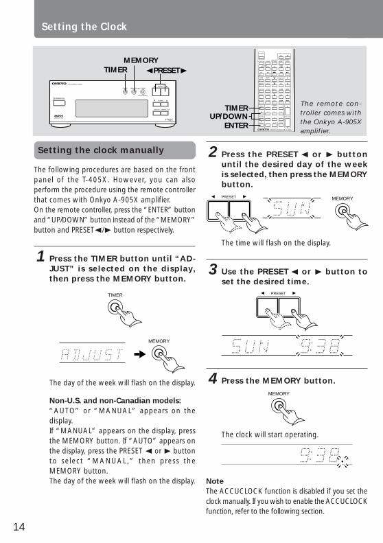
The following procedures are based on the frontpanel of the T-405X. However, you can alsoperform the procedure using the remote controllerthat comes with Onkyo A-905X amplifier.On the remote controller, press the “ENTER”button and “UP/DOWN” button instead of the“MEMORY” button and PRESET√/® buttonrespectively.
Confirming/changing the RDSstation used by ACCUCLOCK
If you wish to know which RDS station has beenused to set the clock by ACCUCLOCK, or to use adifferent RDS station signal to set the clock, followthe steps below:
1 Press the TIMER button repeatedlyuntil “ADJUST” is selected on thedisplay, then press the MEMORYbutton.
TIMER
MEMORY
“AUTO” or “MANUAL” appears on thedisplay.
2 If “AUTO” appears on the display,press the MEMORY button. If“MANUAL” appears on the display,press the PRESET √ or ® button toselect “AUTO,” then press theMEMORY button.
MEMORY
MHz
The example shown above indicates that theACCUCLOCK function uses the RDS station whoseinformation appears on the display (FM 88.10 MHz).If RDS station signals cannot be receivedsuccessfully, “- -.- -” will appear instead of the radiofrequency of the station. If you wish to changethe selected RDS station or if no RDS station isselected, choose the desired RDS station by usingthe PRESET√ or ® button, then press theMEMORY button.
T-405X
FM STEREO TUNER
MEMORYTIMER CLEAR
AUTO/MONO
STANDBY/ON
ACCUCLOCK
TUNING
PRESET
CHARACTERDISPLAY
POWER
CLOCK CALL
TUNERPRESET
SLEEP
FM AM
REPEAT SCROLL
PLAY MODE CLEAR REC
REPEAT RANDOM
MEMORY CLEAR
TIMER 1
ACOUSTICPRESENCE
DVD
2
DISC
CD/MD
EFFECT
PAUSE/STEP
3
4 5 6
UP/DOWN7 8 9
ENTER - - / - - - 10/0 MUTING
VOLUME
G.EQUALIZER
TAPE
MODE
INPUT SELECTOR
MD
CD
RC-398SREMOTE CONTROLLER
TIMER
ENTERUP/DOWN
TIMERMEMORY
√PRESET®
The remote con-troller comes withthe Onkyo A-905Xamplifier.
14
Setting the clock manually
The following procedures are based on the frontpanel of the T-405X. However, you can alsoperform the procedure using the remote controllerthat comes with Onkyo A-905X amplifier.On the remote controller, press the “ENTER” buttonand “UP/DOWN” button instead of the “MEMORY”button and PRESET√/® button respectively.
1 Press the TIMER button until “AD-JUST” is selected on the display,then press the MEMORY button.
TIMER
MEMORY
The day of the week will flash on the display.
Non-U.S. and non-Canadian models:“AUTO” or “MANUAL” appears on thedisplay.If “MANUAL” appears on the display, pressthe MEMORY button. If “AUTO” appears onthe display, press the PRESET √ or ® buttonto select “MANUAL,” then press theMEMORY button.The day of the week will flash on the display.
T-405X
FM STEREO TUNER
MEMORYTIMER CLEAR
AUTO/MONO
STANDBY/ON
ACCUCLOCK
TUNING
PRESET
CHARACTERDISPLAY
POWER
CLOCK CALL
TUNERPRESET
SLEEP
FM AM
REPEAT SCROLL
PLAY MODE CLEAR REC
REPEAT RANDOM
MEMORY CLEAR
TIMER 1
ACOUSTICPRESENCE
DVD
2
DISC
CD/MD
EFFECT
PAUSE/STEP
3
4 5 6
UP/DOWN7 8 9
ENTER - - / - - - 10/0 MUTING
VOLUME
G.EQUALIZER
TAPE
MODE
INPUT SELECTOR
MD
CD
RC-398SREMOTE CONTROLLER
TIMER
ENTERUP/DOWN
TIMERMEMORY
√PRESET®
2 Press the PRESET √ or ® buttonuntil the desired day of the weekis selected, then press the MEMORYbutton.PRESET MEMORY
The time will flash on the display.
3 Use the PRESET √ or ® button toset the desired time.
PRESET
4 Press the MEMORY button.MEMORY
The clock will start operating.
NoteThe ACCUCLOCK function is disabled if you set theclock manually. If you wish to enable the ACCUCLOCKfunction, refer to the following section.
The remote con-troller comes withthe Onkyo A-905Xamplifier.
Setting the Clock

15
Befo
re U
sing
Co
nn
ectio
ns
Oth
er In
form
atio
nO
pera
tion
Clock Call function
You can execute the Clock Call function only byusing the remote controller that is supplied withA-905X amplifier.
1 Press the CLOCK CALL button to dis-play the time, press again to can-cel the time display.
CLOCK CALL
NoteIf the time has not been set, "ADJUST" willflash on the display.
Enabling the ACCUCLOCKfunction
If you have set the clock manually (see page 14),the ACCUCLOCK function is automaticallydisabled. To enable this function, follow the stepsbelow:
1 Press the TIMER button repeatedlyuntil “ADJUST” is selected on thedisplay, then press the MEMORYbutton.
TIMER
MEMORY
“MANUAL” appears on the display.
2 Press the PRESET √ or ® buttonuntil “AUTO” appears, then pressthe MEMORY button.
PRESET
MEMORY
“- -.- -” instead of the radio frequency willappear on the display.
3 Press the MEMORY button.
ACCUCLOCK will become active whenever theT-405X enters STANDBY mode.
T-405X
FM STEREO TUNER
MEMORYTIMER CLEAR
AUTO/MONO
STANDBY/ON
ACCUCLOCK
TUNING
PRESET
CHARACTERDISPLAY
POWER
CLOCK CALL
TUNERPRESET
SLEEP
FM AM
REPEAT SCROLL
PLAY MODE CLEAR REC
REPEAT RANDOM
MEMORY CLEAR
TIMER 1
ACOUSTICPRESENCE
DVD
2
DISC
CD/MD
EFFECT
PAUSE/STEP
3
4 5 6
UP/DOWN7 8 9
ENTER - - / - - - 10/0 MUTING
VOLUME
G.EQUALIZER
TAPE
MODE
INPUT SELECTOR
MD
CD
RC-398SREMOTE CONTROLLER
TIMER
ENTERUP/DOWN
CLOCKCALLTIMER
MEMORY√PRESET®
The remote con-troller comes withthe Onkyo A-905Xamplifier.

16
Receiving stations
Display Options:When you are listening to radio broadcasts, thedisplay usually shows the radio frequency of theselected station. You can, however, change to thecurrent time or character information for theselected station. To do so, press the DISPLAY buttonrepeatedly until the desired indication appears.For more information on how to enter characterinformation, see “Naming a preset station” onpage 19.
Using Auto Memory
This function enables you to store the frequenciesinto memory automatically, without having to gothrough and store each frequency manually.
1 Hold down the MEMORY button fora few seconds. “AUTO” will startflashing on the display. Keep hold-ing down the button for a fewmore seconds to start the AutoMemory function.
Hold down
AUTO
MEMORY
MEMORY
The frequencies are scanned from low to high. Up to20 FM and 10 AM stations (U.S. and Canadian models)and 20 FM stations (non-U.S. and Canadian models)with the best signal quality are selected, sorted in orderfrom low to high frequency, and stored into the presetmemory.
NoteAll stations previously stored in memory will bereplaced with new Auto Memory stations.
Tuning the radio
Make sure that the input selector on the amplifierhas been set to TUNER.
1 Press the STANDBY/ON button.STANDBY/ON
The display changes from clock to frequency(or character) indication.
2 Select FM or AM using the BANDbutton. (only for U.S. and Canadianmodels)
BAND
Use the TUNING †orπ button tochange the frequency.
TUNING
The indoor antenna should be installed on a wallor other surface in the position which gives thebest reception. For more information on howto install the antenna, refer to page 10, 11.
NoteAM reception is available on the U.S. and Canadianmodels.
T-405X
FM STEREO / AM TUNER
MEMORYTIMERBAND CLEAR
AUTO/MONO
STANDBY/ON
TUNING
PRESET
CHARACTERDISPLAY
MEMORY†TUNINGπ
DISPLAY
BANDSTANDBY/ON

17
Befo
re U
sing
Co
nn
ectio
ns
Oth
er In
form
atio
nO
pera
tion
Presetting your favorite stations
You can store your favorite stations in the presetmemory. Follow the procedure below:
1 Select FM or AM using the BANDbutton. (only for U.S. and Canadianmodels)
BAND
Use the TUNING † or π button toselect the frequency of your favor-ite station.
TUNING
To automatically scan the stations, hold downthe TUNING † or π button for more than0.5 seconds, then release the button.Scanning will stop when a station is tuned in.
2 Press the MEMORY button.
The MEMORY indicator lights up and “..... .....”will flash.
Lit Flash
STEREO
MEMORY
MEMORY
3 While “..... .....” is flashing, use thePRESET √ or ® button to select thepreset number into which to storethe station frequency.
The preset number will flash on the display.
STEREO
MHz
AUTO
PRESET
MEMORY
NoteIf you select a preset number into which a stationhas already been programmed, the number willflash rapidly. If you proceed with this number, theoriginal station will be replaced by a new station.
4 While the number is flashing, pressthe MEMORY button.
The frequency will be stored into the selectedpreset.
STEREO
DisappearSelected preset number
MHz
AUTO
MEMORY
Notes• Up to 30 stations can be stored in the preset
memory.• If the FM station received is an RDS station that
has a PS (Program Service Name), the frequencydisplay will change to the PS display. (Refer to page22 for more information on the RDS function.)RDS reception is available only on the Europeanmodels.
T-405X
FM STEREO / AM TUNER
MEMORYTIMERBAND CLEAR
AUTO/MONO
STANDBY/ON
TUNING
PRESET
CHARACTERDISPLAY
†TUNINGπ
BAND MEMORY√PRESET®

18
T-405X
FM STEREO / AM TUNER
MEMORYTIMERBAND CLEAR
AUTO/MONO
STANDBY/ON
TUNING
PRESET
CHARACTERDISPLAY
MEMORYAUTO/MONO
√PRESET®
†TUNINGπ
BAND
Listening to a stereo radiostation
When you tune in a stereo FM station, the STEREOindicator lights up if the signal is sufficiently strong.If the signal is weak, you can still listen to thestation in mono mode. In this case, tune in asfollows.
1 Press the AUTO/MONO button.
The MONO indicator lights up.
STEREO
MHz
Displayed
MONO
AUTO/MONO
CLEAR
2 Select the station you would like tolisten to using the TUNING † or πbutton.
TUNING
Selecting preset stations
Follow the procedure below to select a presetstation stored in memory.
1 Select FM or AM using the BANDbutton. (only for U.S. and Canadianmodels) BAND
Use the PRESET √ or ® button toselect the desired preset station.
PRESET
Clearing preset stations
You can clear preset stations from the preset memory.
1 Select the station as explained inthe previous section.
2 Press and hold the MEMORY but-ton and press the AUTO/MONO but-ton within a second.
“..... ..... ” appears on the display.
MEMORY CLEAR
AUTO/MONO
NoteIf you fail to press the AUTO/MONO button whileholding down the MEMORY button immediately,the AUTO MEMORY function will start operating.
Receiving stations
19
Befo
re U
sing
Co
nn
ectio
ns
Oth
er In
form
atio
nO
pera
tion
Naming a preset station
Naming a preset station
You can name the preset stations so that the name,instead of the frequency, appears on the displaywhen you press the DISPLAY button. (For moreinformation, see “Display options” on page 16.)
NoteYou cannot enter characters for an RDS stationthat has a program service (PS) name, since the PSname has priority over other character information.(For more information on RDS stations, see page 22.)• RDS reception is available only on the European
models.
1 Select the station you wish toname. (See “Selecting preset stations” onpage 18.)
STEREO
MHz
AUTO
2 Press the CHARACTER button.
The T-405X enters character input mode, and“.....” flashes on the display.
STEREOAUTO
Flash
CHARACTER
3 Use the PRESET √ or ® button toselect a character.
The character flashes on the display.
STEREOAUTO
Flash
PRESET
4 Press the MEMORY button to storethe character.
Flashing “.....” mark appears next to the storedcharacter.Repeat the steps 3 and 4 to store morecharacters. You can store up to 8 characters.To enter a space between characters, pressthe MEMORY button. The bar cursor moveson to the next position.
STEREOAUTO
Flash
MEMORY
(continued on the next page)
The following 54 characters can be used: A B C D E F G H I J K L M N O P Q R S
T U V W X Y Z “ & ‘ ( ) * + , - . / = ? [ \ ]| 0 1 2 3 4 5 6 7 8 9
]
T-405X
FM STEREO / AM TUNER
MEMORYTIMERBAND CLEAR
AUTO/MONO
STANDBY/ON
TUNING
PRESET
CHARACTERDISPLAY
MEMORY
CHARACTER
√PRESET®
,

20
T-405X
FM STEREO / AM TUNER
MEMORYTIMERBAND CLEAR
AUTO/MONO
STANDBY/ON
TUNING
PRESET
CHARACTERDISPLAY
CHARACTER
√PRESET® MEMORY
5 When you finish entering all nec-essary characters, press the CHAR-ACTER button to complete the op-eration.
STEREOAUTO
CHARACTER
NoteIf you have not pressed any button for 16 secondsduring the procedure, the operation will completeautomatically.
Changing the existing characters
Follow the procedure below to change the existingcharacters or rename the preset station.
1 Select the station you wish tomodify. (See “Selecting preset stations”on page 18.)
STEREOAUTO
2 Press the CHARACTER button.
The T-405X enters character input mode, andthe first character flashes.
STEREOAUTO
CHARACTER
3 Press the MEMORY button repeatedlyuntil the character that you want tochange flashes.
STEREOAUTO
MEMORY
NoteYou can use the TUNING † or π buttoninstead of the MEMORY button.
Naming preset stations

21
Befo
re U
sing
Co
nn
ectio
ns
Oth
er In
form
atio
nO
pera
tion
4 Use the PRESET √ or ® button tochange the character.
STEREOAUTO
PRESET
5 Press the MEMORY button to storethe character.
MEMORY
6 Press the CHARACTER button tocomplete the operation.
CHARACTER
T-405X
FM STEREO / AM TUNER
MEMORYTIMERBAND CLEAR
AUTO/MONO
STANDBY/ON
TUNING
PRESET
CHARACTERDISPLAY
CHARACTER
AUTO/MONOMEMORY √PRESET®
Clearing all names stored inmemory
Follow the procedure below to delete the nameof the selected preset station.
1 Press the CHARACTER button.
CHARACTER
2 While holding down the MEMORYbutton, press the AUTO/MONO but-ton.
MEMORY CLEAR
AUTO/MONO
The name will be deleted.

22
Receiving RDS (European models only)
RDS reception is available only on the Europeanmodel, and only in areas where RDS broadcastsare available.
What is RDS?Many FM stations now transmit RDS signals whichcontain additional information. RDS provides youwith various services so that you can choose astation broadcasting your favorite categories ofmusic or other information. The information belowis available through the T-405X.
PS: Program Service NameRT: Radio Text
NoteIf radio signals are weak, RDS may not be received.
Displaying Radio Text (RT)
Radio Text can be displayed as follows.NoteIf the station you are listening to is not an RDSstation, no Radio Text will be displayed.
1 Each time you press the DISPLAYbutton, the display changes as fol-lows.
Frequency Entered Character or Program service name
Radio TextClock
DISPLAY
If the current station you are listening to is not anRDS station, only the frequency of the station andthe characters (see page 19) appear. (If nocharacters have been entered, only the frequencyinformation will appear.)When RT is received, it can sometimes takebetween a few seconds and 15 seconds (more orless) to display.Sometimes the following messages will be shownon the display.WAIT: This message indicates that it requires moretime to receive the RT information. When theinformation is received, the characters will scrollacross the display.NO TEXT: This message appears for three secondsand indicates that even though an RDS station isbeing received, the signal does not contain RTinformation.
T-405X
FM STEREO TUNER
MEMORYTIMER CLEAR
AUTO/MONO
STANDBY/ON
ACCUCLOCK
TUNING
PRESET
CHARACTERDISPLAY
DISPLAY

23
Befo
re U
sing
Co
nn
ectio
ns
Oth
er In
form
atio
nO
pera
tion
Using the timer
The T-405X features a Timer function that enables you to start playing or recording a specified componentat a specified time. To use this function, you need to configure a system that includes an ONKYO amplifierA-905X connected to the T-405X and other components via REMOTE CONTROL jacks. Refer to“System connection for use of Timer function” and “Connecting to other components” on pages 7through 9 for more information on making the connections.
Buttons and modes for the Timer function
The following buttons and setting modes are used to operate the Timer function. You can use theremote controller (that comes with the ONKYO amplifier A-905X), as well as the front panel of theT-405X.
TIMER buttonUse this button to select a timer mode. The timer modewill change each time you press this button.
PRESET √/® buttons (T-405X), orUP/DOWN (π/†) buttons (Remote controller)Use these buttons to select the details of the modeor to change values.
MEMORY button (T-405X), orENTER button (Remote controller)Use this button to enter the selected mode ornumbers.
Timer setting modes:• WEEKDAY: This mode enables you to listen to
a specified component at a designated time onweekdays.
• WEEKEND: This mode enables you to listen toa specified component at a designated time onweekends.
• REC: This mode enables you to record yourfavorite broadcasting program(s) starting at adesignated time.
• DAY SET: This mode enables you to changethe day setting (definition) of WEEKDAY orWEEKEND.
• ADJUST: This mode enables you to set andadjust the clock.
The following sections (page 24–28) describeoperations using the front panel of the T-405X.As mentioned above, however, you can alsoperform the following operations from the remotecontroller that comes with the Onkyo A-905Xamplifier.On the remote controller, press the ENTER buttonand UP/DOWN (π/†) buttons instead of theMEMORY button and PRESET √/® buttonsrespectively.
The remote controllercomes with the OnkyoA-905X amplifier.
T-405X
FM STEREO / AM TUNER
MEMORYTIMERBAND CLEAR
AUTO/MONO
STANDBY/ON
TUNING
PRESET
CHARACTERDISPLAY
TIMERMEMORY
√PRESET®
POWER
CLOCK CALL
TUNERPRESET
SLEEP
FM AM
REPEAT SCROLL
PLAY MODE CLEAR REC
REPEAT RANDOM
MEMORY CLEAR
TIMER 1
ACOUSTICPRESENCE
DVD
2
DISC
CD/MD
EFFECT
PAUSE/STEP
3
4 5 6
UP/DOWN7 8 9
ENTER - - / - - - 10/0 MUTING
VOLUME
G.EQUALIZER
TAPE
MODE
INPUT SELECTOR
MD
CD
RC-398SREMOTE CONTROLLER
TIMERUP/DOWN
ENTER
24
POWER
CLOCK CALL
TUNERPRESET
SLEEP
FM AM
REPEAT SCROLL
PLAY MODE CLEAR REC
REPEAT RANDOM
MEMORY CLEAR
TIMER 1
ACOUSTICPRESENCE
DVD
2
DISC
CD/MD
EFFECT
PAUSE/STEP
3
4 5 6
UP/DOWN7 8 9
ENTER - - / - - - 10/0 MUTING
VOLUME
G.EQUALIZER
TAPE
MODE
INPUT SELECTOR
MD
CD
RC-398SREMOTE CONTROLLER
T-405X
FM STEREO / AM TUNER
MEMORYTIMERBAND CLEAR
AUTO/MONO
STANDBY/ON
TUNING
PRESET
CHARACTERDISPLAY TIMER
ENTERUP/DOWN
TIMERMEMORY
√PRESET®
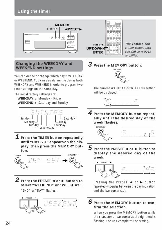
Changing the WEEKDAY andWEEKEND settings
You can define or change which day is WEEKDAYor WEEKEND. You can also define the day as bothWEEKDAY and WEEKEND in order to program twotimer settings on the same day.
The initial factory settings are:WEEKDAY : Monday – FridayWEEKEND : Saturday and Sunday
SundayMonday
TuesdayWednesday
ThursdayFriday
Saturday
1 Press the TIMER button repeatedlyuntil “DAY SET” appears on the dis-play, then press the MEMORY but-ton.
MEMORYTIMER
2 Press the PRESET √ or ® button toselect “WEEKEND” or “WEEKDAY”.
“END” or “DAY” flashes.
PRESET
3 Press the MEMORY button.MEMORY
The current WEEKDAY or WEEKEND settingwill be displayed.
4 Press the MEMORY button repeat-edly until the desired day of theweek flashes.
MEMORY
5 Press the PRESET √ or ® button todisplay the desired day of theweek.
PRESET
Pressing the PRESET √ or ® buttonrepeatedly toggles between the day indicationand the bar cursor (.....).
6 Press the MEMORY button to con-firm the selection.
When you press the MEMORY button whilethe character or bar cursor at the right end isflashing, the unit completes the setting.
The remote con-troller comes withthe Onkyo A-905Xamplifier.
Using the timer
25
Befo
re U
sing
Co
nn
ectio
ns
Oth
er In
form
atio
nO
pera
tion
Programming to play at a specifiedtime
Before using the timer for listening to or recordingbroadcast programs, you need to store the presetstations. (Refer to “Receiving stations” on page16, 17 for information how to preset stations.)
1 Press the TIMER button repeatedlyuntil “WEEKDAY” or “WEEKEND” isdisplayed, and press the MEMORYbutton.
MEMORY
TIMER
2 Press the PRESET √ or ® button toset the ON time, and press theMEMORY button.
STEREOTIMERW.DAY
MEMORY
PRESET
• When you store the ON time, the displayautomatically indicates that the OFF time is onehour after the ON time you specified.
3 Press the PRESET √ or ® button toselect the OFF time, and press theMEMORY button.
STEREOTIMERW.DAY
PRESET
MEMORY
4 Press the PRESET √ or ® button toselect the source (FM/AM/CD/MD/TAPE/LINE-1/LINE-2), and press theMEMORY button.
AUTOTIMERW.DAY
MEMORY
PRESET
If you select “FM” or “AM”, press the PRESET√ or ® button again to select the presetnumber and press the MEMORY button.• AM reception is available only on the U.S. and
Canadian models.(continued on the next page)
POWER
CLOCK CALL
TUNERPRESET
SLEEP
FM AM
REPEAT SCROLL
PLAY MODE CLEAR REC
REPEAT RANDOM
MEMORY CLEAR
TIMER 1
ACOUSTICPRESENCE
DVD
2
DISC
CD/MD
EFFECT
PAUSE/STEP
3
4 5 6
UP/DOWN7 8 9
ENTER - - / - - - 10/0 MUTING
VOLUME
G.EQUALIZER
TAPE
MODE
INPUT SELECTOR
MD
CD
RC-398SREMOTE CONTROLLER
T-405X
FM STEREO / AM TUNER
MEMORYTIMERBAND CLEAR
AUTO/MONO
STANDBY/ON
TUNING
PRESET
CHARACTERDISPLAY TIMER
ENTERUP/DOWN
TIMERMEMORY
√PRESET®
The remote con-troller comes withthe Onkyo A-905Xamplifier.

26
5 Press the STANDBY/ON button onthe Amplifier A-905X to set theSTANDBY mode.
STEREOTIMERW.DAY
STANDBY/ON
STANDBY
(A-905X)
Notes• The clock of the tuner must be set correctly
before programming the timer.• Make sure that the specified source component
is connected to the amplifier, and that the CD,MD, or cassette tape has been inserted into theappropriate component.
• After setting the timer, be sure to set theamplifier in STANDBY mode. If the amplifier isnot in STANDBY mode, the timer will not work.
• Make sure that the POWER switch on the A-905X Amplifier is set to ON.
Programming to record at aspecified time
REC mode of the Timer function enables you torecord a specified source at a specified time.
Notes• To perform timer recording to a tape, you need
to use a cassette tape deck that features the mark, such as the K-505X.
• To perform timer recording to a mini disc, youneed to use an MD recorder that features the
mark, such as the MD-105X.
1 Press the TIMER button repeatedlyuntil “REC” appears on the display,then press the MEMORY button.
MEMORY
TIMER
2 Press the PRESET √ or ® button toselect the day of the week whenyou wish to start recording, thenpress the MEMORY button.
TIMER
REC
MEMORY
PRESET
You can select “NEXT” instead of the day ofthe week. If you do so, recording will start atthe next occurrence of the indicated time.
T-405X
FM STEREO / AM TUNER
MEMORYTIMERBAND CLEAR
AUTO/MONO
STANDBY/ON
TUNING
PRESET
CHARACTERDISPLAY
ENTERUP/DOWN
MEMORY√PRESET®
TIMER
TIMER
POWER
CLOCK CALL
TUNERPRESET
SLEEP
FM AM
REPEAT SCROLL
PLAY MODE CLEAR REC
REPEAT RANDOM
MEMORY CLEAR
TIMER 1
ACOUSTICPRESENCE
DVD
2
DISC
CD/MD
EFFECT
PAUSE/STEP
3
4 5 6
UP/DOWN7 8 9
ENTER - - / - - - 10/0 MUTING
VOLUME
G.EQUALIZER
TAPE
MODE
INPUT SELECTOR
MD
CD
RC-398SREMOTE CONTROLLER
The remote con-troller comes withthe Onkyo A-905Xamplifier.
Using the timer

27
Befo
re U
sing
Co
nn
ectio
ns
Oth
er In
form
atio
nO
pera
tion
POWER
CLOCK CALL
TUNERPRESET
SLEEP
FM AM
REPEAT SCROLL
PLAY MODE CLEAR REC
REPEAT RANDOM
MEMORY CLEAR
TIMER 1
ACOUSTICPRESENCE
DVD
2
DISC
CD/MD
EFFECT
PAUSE/STEP
3
4 5 6
UP/DOWN7 8 9
ENTER - - / - - - 10/0 MUTING
VOLUME
G.EQUALIZER
TAPE
MODE
INPUT SELECTOR
MD
CD
RC-398SREMOTE CONTROLLER
T-405X
FM STEREO / AM TUNER
MEMORYTIMERBAND CLEAR
AUTO/MONO
STANDBY/ON
TUNING
PRESET
CHARACTERDISPLAY TIMER
ENTERUP/DOWN
TIMERMEMORY
√PRESET®
3 Press the PRESET √ or ® button toset the ON time, and press theMEMORY button.
STEREOTIMER
REC
PRESET
MEMORY
• When you store the ON time, the displayautomatically indicates that the OFF time is onehour after the ON time you specified.
4 Press the PRESET √ or ® button toset the OFF time, then press theMEMORY button.
STEREOTIMER
REC
PRESET
MEMORY
5 Press the PRESET √ or ® button toselect the source (FM/AM/LINE-1/LINE-2), and press the MEMORYbutton.
STEREO
MHz
TIMER
REC
PRESET
MEMORY
If you select “FM” or ”AM“, press the PRESET√ or ® buttons again to select the presetnumber, then press the MEMORY button.• AM reception is available only on the U.S.
and Canadian models.
6 Press the PRESET √ or ® button toselect the recording component(MD REC, TAPE REC, or MD/TAPEREC), and press the MEMORY but-ton.
STEREOAUTOTIMER
REC
PRESET
MEMORY
(continued on the next page)
The remote con-troller comes withthe Onkyo A-905Xamplifier.

28
7 Press the STANDBY/ON button onthe Amplifier A-905X to set theSTANDBY mode.
STEREOTIMER
REC
STANDBY/ON
STANDBY
(A-905X)
Notes• Since muting is automatically turned on when
the timer is used to record, the sound cannotbe heard during recording. To monitor recording,press the MUTING button on the remotecontroller to cancel muting.
• Timer recording is activated once. Afterrecording, the REC mode setting will becancelled.
• After setting the timer, be sure to set theamplifier in STANDBY mode. If the amplifier isnot in STANDBY mode, the timer will not work.
• Make sure that the POWER switch on the A-905X Amplifier is set to ON.
Switching the timer ON/OFF
You can switch the timer ON/OFF to cancel thetimer setting, to enable the timer again, or toperform timer recording again.When the Timer function is enabled, the selectedtimer mode such as “WEEKDAY”, “WEEKEND”, and“REC” appears in the upper left corner of the display.
NoteTo switch the timer ON, first you need to programthe time value.
1 Press the TIMER button repeatedlyuntil the timer mode (WEEKDAY,WEEKEND or REC) that you wish toenable or disable appears on theupper left corner of the display.
TIMER
2 Press the PRESET √ or ® button toswitch the selected mode ON orOFF.
AUTOTIMERW.DAY
PRESET
3 Press the MEMORY button to con-firm the selection.
MEMORY
T-405X
FM STEREO / AM TUNER
MEMORYTIMERBAND CLEAR
AUTO/MONO
STANDBY/ON
TUNING
PRESET
CHARACTERDISPLAY
ENTERUP/DOWN
MEMORY√PRESET®
TIMER
TIMER
POWER
CLOCK CALL
TUNERPRESET
SLEEP
FM AM
REPEAT SCROLL
PLAY MODE CLEAR REC
REPEAT RANDOM
MEMORY CLEAR
TIMER 1
ACOUSTICPRESENCE
DVD
2
DISC
CD/MD
EFFECT
PAUSE/STEP
3
4 5 6
UP/DOWN7 8 9
ENTER - - / - - - 10/0 MUTING
VOLUME
G.EQUALIZER
TAPE
MODE
INPUT SELECTOR
MD
CD
RC-398SREMOTE CONTROLLER
The remote con-troller comes withthe Onkyo A-905Xamplifier.
Using the timer

29
Befo
re U
sing
Co
nn
ectio
ns
Oth
er In
form
atio
nO
pera
tion
Notes for timer setting
• Make sure that the clock has been set correctlybefore setting the timer.
• After setting the timer, be sure to set theapmlifier in standby mode. If the amplifier is notin standby mode, the timer will not work.
• When the power is turned on by one of thetimer mode settings, the other timer modes maynot be activated at their ON time. The powerwill be switched off by the first timer mode atits OFF time. (See the figure below.)
• If you press the SLEEP button during timer playor timer recording, the power will be switchedoff at the SLEEP timer’s OFF time.
• If more than two timer mode settings are madeat the same time, the “WEEKDAY” setting hasthe priority over the “WEEKEND” setting. The“REC” mode setting has no priority.
• The timer recording setting will be cancelled ifthe recording does not start at the ON time (forexample, if the power is already on).
WEEKDAY
REC
WEEKEND
activate
activate
Time
ON
9:00
OFF
10:00
ON
11:00
OFF
12:00
not activate
Sleep function
The Sleep function can be performed only by usingremote controller that comes with the amplifierA-905X.The SLEEP timer automatically sets the entiresystem to standby mode after a specified periodof time.
1 Start playing something you wouldlike to listen to.
(CD, tape, MD or radio broadcast).
2 Press the SLEEP button repeatedlyto set the desired sleep time.
STEREOMIN
AUTOTIMER
SLEEP
SLEEP
The time value will decrease from 90 minutesto 10 minutes in steps of 10 minutes.After a specified period of time, the powerwill be switched off automatically.
• To check the remaining time while the SLEEPfunction is active, press the SLEEP button.
Cancelling the SLEEP settingPress the SLEEP button repeatedly until the SLEEPindicator on the display disappears.
POWER
CLOCK CALL
TUNERPRESET
SLEEP
FM AM
REPEAT SCROLL
PLAY MODE CLEAR REC
REPEAT RANDOM
MEMORY CLEAR
TIMER 1
ACOUSTICPRESENCE
DVD
2
DISC
CD/MD
EFFECT
PAUSE/STEP
3
4 5 6
UP/DOWN7 8 9
ENTER - - / - - - 10/0 MUTING
VOLUME
G.EQUALIZER
TAPE
MODE
INPUT SELECTOR
MD
CD
RC-398SREMOTE CONTROLLER
SLEEP
The remote con-troller comes withthe Onkyo A-905Xamplifier.

30
TroubleshootingSymptom
No power.
AM stations cannot bereceived.
Buzzing noise on AM(particularly conspicuousat night or with weak sta-tions).
High-pitched noise orbuzzing noise on AM.
Crackling noise on AM,FM.
Tuning indicators and ste-reo indicator light butsound is distorted andseparation is bad.
Tuning indicators andstereo indicator flickerand hiss is heard on FM.
No station or undesiredstation is recalled when aPreset button is pressed.
The RDS function doesnot work.
ACCUCLOCK functiondoes not work.
Remedy
• Connect power cord.
• Connect the supplied AM loopantenna to the AM antennaterminals.
• Move the AM loop antenna todifferent position.
• Set up an outdoor AM antenna.
• Place the AM loop antenna as faras possible from the TV.
• Move unit away from TV set.
• Move the antenna as far away aspossible from the fluorescent lamp.
• Install an outdoor FM antenna asfar away as possible from the road.
• Change to FM indoor antenna.
• Use antenna that has betterdirectivity and select a point withthe least distortion.
• Install an outdoor FM antenna.
• Change the position or direction ofthe outdoor antenna.
• Switch to mono reception. (Evenstereo broadcasts will be heard inmono.)
• The memory contents are lost if thepower is not turned on and off afew times each month. Store allstations in the memory again andremember to turn the power on andoff a few times each month.
• Receive an RDS station.
• Install an outdoor FM antenna.
• Change the position or direction ofthe outdoor antenna.
• Move the antenna as far away aspossible from fluorescent lamps.
• Install an outdoor FM antenna.
• See the remedies for the RDSfunction problem above.
• Set and adjust according toinstructions above.
Cause
• Power cord is disconnected.
• AM loop antenna is not attached.
• Noise from electrical apparatus suchas fluorescent lamp.
• Noise from TV set.
• Noise caused by turning a fluorescentlamp on and off.
• Noise from automobile ignition.
• Station is too strong.
• Multiple reflection of the radio wavesbecause of ta l l bu i ld ings ormountains.
• Station is too weak.
• Stereo FM broadcasts cover onlyabout half the distance of an ordinarybroadcast.
• The power cord has been unpluggedfor a long time.
• The station is not an RDS station.
• The reception station signal is tooweak.
• Too much interference.
• The station is not an RDS station, orreceived signal is too weak.
• RDS broadcasts cannot be received.
• Excessive electrical interference may temporarily render this system’s sensitive microcomputerinoperable. If this happens, unplug the system for at least five seconds.
Other Information
31
Befo
re U
sing
Co
nn
ectio
ns
Oth
er In
form
atio
nO
pera
tion
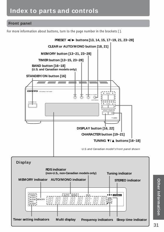
Index to parts and controls
Front panel
TUNING
T-405X
FM STEREO / AM TUNER
MEMORYTIMERBANDPRESET
CHARACTERDISPLAY
CLEAR
AUTO/MONO
STANDBY/ON
PRESET √/® buttons [13, 14, 15, 17~19, 21, 23~28]
TUNING †/π buttons [16~18]
DISPLAY button [16, 22]
CHARACTER button [19~21]
MEMORY button [13~21, 23~28]
TIMER button [13~15, 23~28]
BAND button [16~18] (U.S. and Canadian models only)
STANDBY/ON button [16]
CLEAR or AUTO/MONO button [18, 21]
U.S. and Canadian model’s front panel shown
STEREOMINkHzMHz
MONO RDSAUTOTIMERW.DAYW.ENDRECSLEEP
MEMORY
AUTO/MONO indicatorMEMORY indicator
Multi display
Tuning indicator
STEREO indicator
Timer setting indicators Frequency indicators Sleep time indicator
RDS indicator(non-U.S., non-Canadian models only)
For more information about buttons, turn to the page number in the brackets [ ].
Display

32
Sales & Product Planning Div. : 2-1, Nisshin-cho, Neyagawa-shi, OSAKA 572-8540, JAPANTel: 0720-31-8111 Fax: 0720-33-5222 http://www.onkyo-intl.com
ONKYO U.S.A. CORPORATION18 Park Way, Upper Saddle River, N.J. 07458, U.S.A.Tel: 201-785-2600 Fax: 201-785-2650 http://www.onkyousa.com
ONKYO EUROPE ELECTRONICS GmbHLiegnitzerstrasse 6, 82194 Groebenzell, GERMANYTel: +49-8142-4401-0 Fax: +49-8142-4401-555 http://www.onkyo.net
ONKYO CHINA LIMITEDUnits 2102-2107, Metroplaza Tower I, 223 Hing Fong Road, Kwai Chung,N.T., HONG KONG Tel: 852 2429 3118 Fax: 852 2428 9039
E
http://www.onkyo.co.jp/HOMEPAGE
SN 29342744Printed in Japan
I9905-1
Specifications
FMTuning Range:
87.90 – 107.90 MHz, 200 kHz steps (U.S. & Canadian models)87.50 – 108.00 MHz, 50 kHz steps (Ohter area models)
Usable Sensitivity:Mono : 12.8 dBf 1.2 µV, 75 Ohms IHFStereo : 19.2 dBf 2.5 µV, 75 Ohms IHF
50dB Quieting Sensitivity:Mono : 18.0 dBf 2.2 µV, 75 OhmsStereo : 38.0 dBf 22 µV, 75 Ohms
Capture Ratio : 1.5 dBImage Rejection Ratio : 85 dBIF Rejection Ratio : 90 dBSignal-to-Noise Ratio : Mono: 73 dB IHF
Stereo: 66 dB IHFSelectivity : 50 dB DIN (±300 kHz, 40 kHz dev.)AM Suppression Ratio : 50 dBTotal Harmonic Distortion : Mono: 0.5%
Stereo: 0.8%Frequency Response : 30 – 15,000 Hz (±1.5 dB)Stereo Separation : 40 dB at 1 kHz
30 dB at 70 – 10,000 HzOutput Level : 0.5 V (U.S.& Canadian models)
0.75 V (Other area models)Muting Level : 17.2 dBf 2.0 µV, 75 Ohms
AMTuning Range :
530 – 1,710 kHz, 10 kHz stepsUsable Sensitivity : 30 µVImage Rejection Ratio : 30 dBIF Rejection Ratio : 40 dBSignal-to-Noise Ratio : 40 dBTotal Harmonic Distortion : 0.8%Output Level: 0.15 V
GeneralPower Supply :
AC 120 V, 60 HzAC 230 V, 50 Hz
Power Consumption : 9 WDimensions (W × H × D) :
205 × 76 × 279 mm8-1/16" × 3" × 11"
Weight : 1.7 kg, 3.7 lbs.
AM reception is available only on the U.S. and Canadianmodels.
Specifications and external appearance are subject tochange without notice as a result of product improvement.