stereo light probe -...
TRANSCRIPT

EUROGRAPHICS 2008 / G. Drettakis and R. Scopigno(Guest Editors)
Volume 27 (2008), Number 2
Stereo Light Probe
Massimiliano Corsini, Marco Callieri and Paolo Cignoni
Visual Computing Lab, ISTI - Area della ricerca CNRVia G. Moruzzi 1, 56124, Pisa, Italy
Email: {corsini, callieri, cignoni}@isti.cnr.it
Figure 1: (Left) Three models of the Michelangelo’s David illuminated with a spatially-varying lighting environment capturedwith the proposed Stereo Light Probe device. (Right) The same scene with a lighting environment captured with the classicalapproach of single reflective ball.
Abstract
In this paper we present a practical, simple and robust method to acquire the spatially-varying illumination of areal-world scene. The basic idea of the proposed method is to acquire the radiance distribution of the scene usinghigh-dynamic range images of two reflective balls. The use of two light probes instead of a single one allows toestimate, not only the direction and intensity of the light sources, but also the actual position in space of the lightsources. To robustly achieve this goal we first rectify the two input spherical images, then, using a region-basedstereo matching algorithm, we establish correspondences and compute the position of each light. The radiancedistribution so obtained can be used for augmented reality applications, photo-realistic rendering and accuratereflectance properties estimation. The accuracy and the effectiveness of the method have been tested by measuringthe computed light position and rendering synthetic version of a real object in the same scene. The comparisonwith standard method that uses a simple spherical lighting environment is also shown.
Categories and Subject Descriptors (according to ACM CCS): I.3.3 [Computer Graphics]: Illumination Estimation,Light Fields, Image-Based Lighting, Reflectance and Shading I.3.7 [Three-Dimensional Graphics and Realism]:
1. Introduction
In recent years the convergence of Computer Vision andComputer Graphics is becoming more and more evident andimportant both from a theoretical point of view to developnew results in the field of appearance acquisition and mod-eling and for the development of advanced graphics appli-
cations. One of the main task of this convergence concernsthe acquisition and rendering of the reflectance propertiesof a given scene. Only an accurate estimation of the re-flectance properties of a surface make possible to producephoto-realistic faithful rendering of acquired surfaces: a crit-ical point of the process of reflectance properties acquisition
c© 2008 The Author(s)Journal compilation c© 2008 The Eurographics Association and Blackwell Publishing Ltd.Published by Blackwell Publishing, 9600 Garsington Road, Oxford OX4 2DQ, UK and350 Main Street, Malden, MA 02148, USA.
M. Corsini & M. Callieri & P. Cignoni / Stereo Light Probe
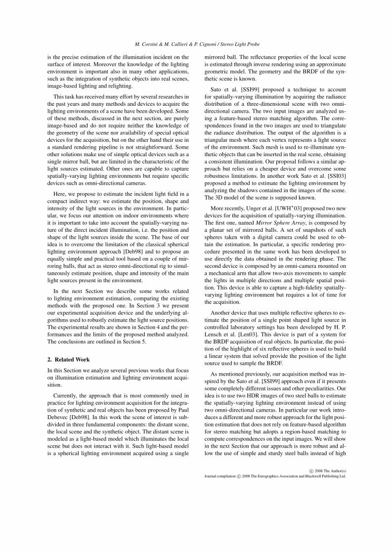
is the precise estimation of the illumination incident on thesurface of interest. Moreover the knowledge of the lightingenvironment is important also in many other applications,such as the integration of synthetic objects into real scenes,image-based lighting and relighting.
This task has received many effort by several researches inthe past years and many methods and devices to acquire thelighting environments of a scene have been developed. Someof these methods, discussed in the next section, are purelyimage-based and do not require neither the knowledge ofthe geometry of the scene nor availability of special opticaldevices for the acquisition, but on the other hand their use ina standard rendering pipeline is not straightforward. Someother solutions make use of simple optical devices such as asingle mirror ball, but are limited in the characteristic of thelight sources estimated. Other ones are capable to capturespatially-varying lighting environments but require specificdevices such as omni-directional cameras.
Here, we propose to estimate the incident light field in acompact indirect way: we estimate the position, shape andintensity of the light sources in the environment. In partic-ular, we focus our attention on indoor environments whereit is important to take into account the spatially-varying na-ture of the direct incident illumination, i.e. the position andshape of the light sources inside the scene. The base of ouridea is to overcome the limitation of the classical sphericallighting environment approach [Deb98] and to propose anequally simple and practical tool based on a couple of mir-roring balls, that act as stereo omni-directional rig to simul-taneously estimate position, shape and intensity of the mainlight sources present in the environment.
In the next Section we describe some works relatedto lighting environment estimation, comparing the existingmethods with the proposed one. In Section 3 we presentour experimental acquisition device and the underlying al-gorithms used to robustly estimate the light source positions.The experimental results are shown in Section 4 and the per-formances and the limits of the proposed method analyzed.The conclusions are outlined in Section 5.
2. Related Work
In this Section we analyze several previous works that focuson illumination estimation and lighting environment acqui-sition.
Currently, the approach that is most commonly used inpractice for lighting environment acquisition for the integra-tion of synthetic and real objects has been proposed by PaulDebevec [Deb98]. In this work the scene of interest is sub-divided in three fundamental components: the distant scene,the local scene and the synthetic object. The distant scene ismodeled as a light-based model which illuminates the localscene but does not interact with it. Such light-based modelis a spherical lighting environment acquired using a single
mirrored ball. The reflectance properties of the local sceneis estimated through inverse rendering using an approximategeometric model. The geometry and the BRDF of the syn-thetic scene is known.
Sato et al. [SSI99] proposed a technique to accountfor spatially-varying illumination by acquiring the radiancedistribution of a three-dimensional scene with two omni-directional camera. The two input images are analyzed us-ing a feature-based stereo matching algorithm. The corre-spondences found in the two images are used to triangulatethe radiance distribution. The output of the algorithm is atriangular mesh where each vertex represents a light sourceof the environment. Such mesh is used to re-illuminate syn-thetic objects that can be inserted in the real scene, obtaininga consistent illumination. Our proposal follows a similar ap-proach but relies on a cheaper device and overcome somerobustness limitations. In another work Sato et al. [SSI03]proposed a method to estimate the lighting environment byanalyzing the shadows contained in the images of the scene.The 3D model of the scene is supposed known.
More recently, Unger et al. [UWH∗03] proposed two newdevices for the acquisition of spatially-varying illumination.The first one, named Mirror Sphere Array, is composed bya planar set of mirrored balls. A set of snapshots of suchspheres taken with a digital camera could be used to ob-tain the estimation. In particular, a specific rendering pro-cedure presented in the same work has been developed touse directly the data obtained in the rendering phase. Thesecond device is composed by an omni-camera mounted ona mechanical arm that allow two-axis movements to samplethe lights in multiple directions and multiple spatial posi-tion. This device is able to capture a high-fidelity spatially-varying lighting environment but requires a lot of time forthe acquisition.
Another device that uses multiple reflective spheres to es-timate the position of a single point shaped light source incontrolled laboratory settings has been developed by H. P.Lensch et al. [Len03]. This device is part of a system forthe BRDF acquisition of real objects. In particular, the posi-tion of the highlight of six reflective spheres is used to builda linear system that solved provide the position of the lightsource used to sample the BRDF.
As mentioned previously, our acquisition method was in-spired by the Sato et al. [SSI99] approach even if it presentssome completely different issues and other peculiarities. Ouridea is to use two HDR images of two steel balls to estimatethe spatially-varying lighting environment instead of usingtwo omni-directional cameras. In particular our work intro-duces a different and more robust approach for the light posi-tion estimation that does not rely on feature-based algorithmfor stereo matching but adopts a region-based matching tocompute correspondences on the input images. We will showin the next Section that our approach is more robust and al-low the use of simple and sturdy steel balls instead of high
c© 2008 The Author(s)Journal compilation c© 2008 The Eurographics Association and Blackwell Publishing Ltd.

M. Corsini & M. Callieri & P. Cignoni / Stereo Light Probe
quality mirroring spheres or costly omnidirectional cameras.Another difference with the work of Sato et al. is that we usea different representation of the radiance distribution. WhileSato et al. use a triangular mesh we opt for a set of omni-directional point lights distributed according to the real lightsources positioned inside the scene. This kind of representa-tion allows a simpler integration with existing rendering en-gines and make our proposal more practical from the enduserperspective. Moreover, the many-lights rendering problemshas received increasingly attention during the last years mak-ing this representation feasible also for the next-gen render-ing engines [HPB07, WABG06, WFA∗05].
A detailed overview of recent advance in omni-directionalstereo vision is not reported here. Interested people couldrefer to recent papers about this topic such as [HLH06,SY05,DS02, GD03] for an in-depth examination.
3. Algorithm
Our algorithm consists of five steps. In the first step two highdynamic range images of two reflective balls are acquiredby taking multiple shots at different exposure with a digi-tal camera. Each ball is photographed separately. This twoHDR images (indicated with I1 and I2 in the following) arethe only required input of the algorithm. Then, the camerais calibrated using reference points placed around the sup-port of each probe. In the third step the recovered extrin-sic and intrinsic parameters of the camera are used to rec-tify the spherical images of the light reflected by the ballsobtaining a rectified reflected stereo pair (I1 and I2). Thefourth step consists of establishing the correspondences be-tween regions representing the light sources in the left andright rectified images. At this point, the position of eachlight source can be easily calculated by intersection of thecorresponding reflected rays. The absolute intensity of thelights is recovered from the values of the HDR images cor-rected with the recovered distance of the lights from the lightprobes. The intensity of the lights is given by the values ofthe HDR images, since such values are proportional to theradiance of the scene. At the end of these processing stepsthe radiance distribution of the environments is determinedand stored as a set of point light sources in the scene space.
A detailed description of our acquisition device and eachphase of the algorithm described are presented in the follow-ing subsections.
3.1. The acquisition device
As just previously mentioned our acquisition device con-sists of two reflective spheres aligned on a support platformand a semi-professional digital camera (see Figure 2). Morespecifically, we use two steel balls with a reflection coeffi-cient of about 0.6. Chrome balls can provide more accurateresults since they are more reflective and polished, neverthe-less since this is an experimental device we decide to use
Figure 2: The experimental acquisition device.
steel balls that are more robust while maintaining a goodreflectivity. The diameter of the steel balls used is 60 mm.The balls are positioned over a calibration pattern shownin the particular of the Figure 2. The distance between thespheres is 65 cm. The left sphere, without loss of general-ity, is assumed to be the reference one. The origin of theworld coordinate system is assumed to be coincident withthis sphere. The snapshots of each ball were captured usinga Canon DS350 digital camera fixed on a tripod. A macroview is used in order to reduce lens distortion. During the ac-quisition phase two sets of snapshots, one for the left sphereand another one for the right one, with different exposure aretaken in order to produce two high-dynamic range images;in this way we obtain values proportional to the scene radi-ance. The HDR images are generated using the HDRShopsoftware [Uni]. The lighting environment we were workingwith did not presented a very high dynamic range like anoutdoor scene; hence it was sufficient to use 5 shots to createeach HDR image. The exposure settings used are: 1/40th,1/20th, 1/10th, 1/5th, 0.4 seconds. Due to the intrinsic na-ture of the spherical reflection, using a single view implya poor sampling of some portion of the surrounding space.This problem can be alleviated by taking the shots from dif-ferent viewpoint and blend them together to remove the re-gion of poor sampling. In the following examples to demon-strate the robustness of the proposed approach we have al-ways used a single HDR image, hence a single viewpoint,for each sphere.
3.2. Camera Calibration
The position of the camera with respect to each steel ball iscomputed using as reference points the corners of referencesymbols and small wooden boxes positioned around the sup-port of each sphere. The intrinsic and extrinsic parametersare estimated with the popular camera calibration algorithmof Roger Tsai [Tsa87]. The calibration has to be very accu-rate in order to minimize problems during the rectificationand the next correspondences matching phase. In fact, if thecamera parameters are imprecise the mapping of the reflec-tions on the rectified spherical stereo pairs become inexactand the correspondences cannot be calculated reliably. The
c© 2008 The Author(s)Journal compilation c© 2008 The Eurographics Association and Blackwell Publishing Ltd.
M. Corsini & M. Callieri & P. Cignoni / Stereo Light Probe
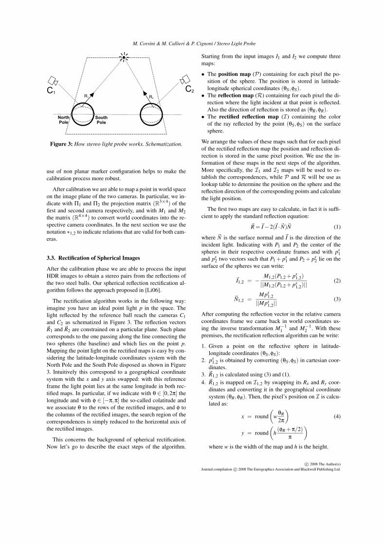
Figure 3: How stereo light probe works. Schematization.
use of non planar marker configuration helps to make thecalibration process more robust.
After calibration we are able to map a point in world spaceon the image plane of the two cameras. In particular, we in-dicate with Π1 and Π2 the projection matrix (R3×4) of thefirst and second camera respectively, and with M1 and M2the matrix (R4×4) to convert world coordinates into the re-spective camera coordinates. In the next section we use thenotation ∗1,2 to indicate relations that are valid for both cam-eras.
3.3. Rectification of Spherical Images
After the calibration phase we are able to process the inputHDR images to obtain a stereo pairs from the reflections ofthe two steel balls. Our spherical reflection rectification al-gorithm follows the approach proposed in [Li06].
The rectification algorithm works in the following way:imagine you have an ideal point light p in the space. Thelight reflected by the reference ball reach the cameras C1and C2 as schematized in Figure 3. The reflection vectors~R1 and ~R2 are constrained on a particular plane. Such planecorresponds to the one passing along the line connecting thetwo spheres (the baseline) and which lies on the point p.Mapping the point light on the rectified maps is easy by con-sidering the latitude-longitude coordinates system with theNorth Pole and the South Pole disposed as shown in Figure3. Intuitively this correspond to a geographical coordinatesystem with the x and y axis swapped: with this referenceframe the light point lies at the same longitude in both rec-tified maps. In particular, if we indicate with θ ∈ [0,2π] thelongitude and with φ ∈ [−π,π] the so-called colatitude andwe associate θ to the rows of the rectified images, and φ tothe columns of the rectified images, the search region of thecorrespondences is simply reduced to the horizontal axis ofthe rectified images.
This concerns the background of spherical rectification.Now let’s go to describe the exact steps of the algorithm.
Starting from the input images I1 and I2 we compute threemaps:
• The position map (P) containing for each pixel the po-sition of the sphere. The position is stored in latitude-longitude spherical coordinates (θS,φS).
• The reflection map (R) containing for each pixel the di-rection where the light incident at that point is reflected.Also the direction of reflection is stored as (θR,φR).
• The rectified reflection map (I) containing the colorof the ray reflected by the point (θS,φS) on the surfacesphere.
We arrange the values of these maps such that for each pixelof the rectified reflection map the position and reflection di-rection is stored in the same pixel position. We use the in-formation of these maps in the next steps of the algorithm.More specifically, the I1 and I2 maps will be used to es-tablish the correspondences, while P and R will be use aslookup table to determine the position on the sphere and thereflection direction of the corresponding points and calculatethe light position.
The first two maps are easy to calculate, in fact it is suffi-cient to apply the standard reflection equation:
~R =~I−2(~I ·~N)~N (1)
where ~N is the surface normal and ~I is the direction of theincident light. Indicating with P1 and P2 the center of thespheres in their respective coordinate frames and with ps
1and ps
2 two vectors such that P1 + ps1 and P2 + ps
2 lie on thesurface of the spheres we can write:
~I1,2 = −M1,2(P1,2 + ps
1,2)||M1,2(P1,2 + ps
1,2)||(2)
~N1,2 =Mps
1,2
||Mps1,2||
(3)
After computing the reflection vector in the relative cameracoordinates frame we came back in world coordinates us-ing the inverse transformation M−1
1 and M−12 . With these
premises, the rectification reflection algorithm can be write:
1. Given a point on the reflective sphere in latitude-longitude coordinates (θS,φS):
2. ps1,2 is obtained by converting (θS,φS) in cartesian coor-
dinates.3. ~R1,2 is calculated using (3) and (1).4. ~R1,2 is mapped on I1,2 by swapping its Rx and Ry coor-
dinates and converting it in the geographical coordinatesystem (θR,φR). Then, the pixel’s position on I is calcu-lated as:
x = round(
wθR
2π
)(4)
y = round(
h(φR +π/2)
π
)where w is the width of the map and h is the height.
c© 2008 The Author(s)Journal compilation c© 2008 The Eurographics Association and Blackwell Publishing Ltd.

M. Corsini & M. Callieri & P. Cignoni / Stereo Light Probe
Figure 4: (From Left-to-Right) The input images. The rectified reflection stereo pair. The RGB coded position and reflectionlookup maps (for each pixel they code the position and reflection direction of the corresponding point on the sphere surface).
5. To determine the color of the sphere point (θS,φS) weproject on the camera image plane the point P1,2 + ps
1,2.Hence, I1,2(x,y) = Π1,2(P1,2 + ps
1,2)6. (θS,φS) is stored in P1,2(x,y).7. (θR,φR)1,2 is stored in R1,2(x,y).
This steps are iterated over several values of (θS,φS) span-ning the ranges [0,2π) for θ and the range [−π,π) for φ. Thesampling step is chosen in order to fill almost all the valuesof the pre-computed maps. This corresponds to over-samplethe sphere surface.
Figure 4 shows the resulting maps. The resolution of suchmaps is 720×1440, encoding a good resolution in (θ,φ) ('0.25 degrees). As it is possible to notice the light sources lieapproximately at the same longitude in the rectified stereopairs as expected.
3.4. Correspondences Estimation
At this point we have to estimate the correspondences be-tween I1 and I2 in order to calculate the position of eachirradiating element. To achieve this goal we opt for a region-based approach. This way of proceed is motivated by somepreliminary experiments with multi-window stereo match-ing algorithm like [IB94] and [FRT97]. In some cases thesecorrelation-based approaches are not able to compute reli-able correspondences. This is caused by the fact that, de-pending on the position of the light sources, their shapecould be severely distorted when projected on the rectifiedreflection maps. To accomplish for such distortions we de-tected blobs that represent the light sources of the scene inthe rectified reflection maps and then we associate them.
The blob detection estimation is subdivided essentially intwo parts. In the first part each HDR image is filtered in orderto simplify the matching. Two filters are applied: a smooth-ing filter to reduce noise and make the image values moreuniform, and a threshold filter in order to eliminate the el-ements of the scene that not irradiate sufficient amount ofenergy. Thanks to the HDR it is particularly simple to dis-
criminate between the light sources and the other elementsof the scene. The indirect illumination sources can be alsoidentified with a careful choice of thresholds. In this first pro-totype we decide to set the threshold such that only the lightsources are considered. More specifically the threshold is setas a percentage of the maximum radiance value (75%). Afterthe thresholding we obtain non-uniform group of pixels thatwe make uniform by the application of multiple passes of adilation filter followed by an erosion one. The kernel size ofthese filters depends on the dimensions of I1 and I2.
After identifying the blobs in the two images, the asso-ciation is easily done by taking into account that the sameblobs have to lie at the same longitude. Hence, each blobs inthe first image is associated to the blob in the second imagewith the minimum latitude distance and within a pre-definedsmall range of longitude.
It is important to underline that this method to computecorresponding regions can be extended in a natural way byemploying a more sophisticated segmentation algorithm forblob detection. For example by using a mean shift algo-rithm [CM02] to segment the elements of the scene it couldbe possible to associate in a robust way not only the regionsthat represent light sources but also those ones which irra-diate a significative amount of indirect light. This segmen-tation could be used also to compute an approximated es-timation of the geometry of the scene. In this work we donot present results in this direction leaving it as a promisingfuture improvements of the Stereo Light Probe device.
3.5. Radiance Distribution Estimation
After having established the correspondences betweenbrighter regions, the radiance distribution of the environmentis obtained by sampling the corresponding blobs and com-puting the intersections between such samples.
Each blob is sampled by considering its center and itsprincipal directions computed with standard PCA. The lo-cal coordinates are relative to the size of the blob and nor-
c© 2008 The Author(s)Journal compilation c© 2008 The Eurographics Association and Blackwell Publishing Ltd.

M. Corsini & M. Callieri & P. Cignoni / Stereo Light Probe
Figure 5: Blob sampling.
malized in the range [−1,1]. The samples are calculated bysubdividing the oriented bounding-box of the blob in a pre-defined number of intervals (see figure 5).
Each sample is used to lookup P1,2 and R1,2 obtainingthe position (o1 and o2) and the direction (~d1 and ~d2) of thetwo reflected rays. We use such information to establish theposition of the light sources by intersecting these rays. Sinceit is very difficult that these two lines intersect at an exactpoint we calculate the point nearest to the two reflected rays.We use the method by Goldman [Gol90] to obtain the twonearest points on the rays and then we consider the mean be-tween these two points as the light position. This kind of lin-ear sampling could introduce a slightly amount of distortionsdue to the fact that the sampling does not follow the shapeof the blob but it is linear with respect to the computed ori-ented bounding-box. To alleviate this problem the bounding-box can be hierarchically subdivided into smaller orientedbounding-box in order to best approximate the shape of theblob.
Each light point is characterized also by the intensity andthe color of the light emitted. The color of the light is de-termined by mapping the corresponding position o1 on thereference sphere (I1) and by multiplying this value accord-ing to the reflection coefficients of the steel ball. Such coef-ficients are obtained by taking a photograph of the steel ballsreflecting a white paper and calculating the ratio between theRGB components of the paper reflected by the sphere withthe components of the paper in the photo. The light intensityis corrected by two factors. The first factor takes into accountthe quadratic distance of the point from the reference sphere.The second factor is used to make the resulting light intensityindependent of the number of samples (Nsamples) used dur-ing the blob sampling. The latter scale factor is calculatedaccording to the formula:
k =A
Nsamples(5)
where A is the area of the light source. More precisely thescale factor k is normalized such as the light source withthe minimum area has k = 1. The area of the light sourceis computed considering the sum of the area of the recon-structed patches. Each patch is identified by four adjacentpoints. Figure 6 shows an example of the results of estima-tion of a room with two fluorescent lamps (120 samples has
Figure 6: Results of the estimation of a room with two fluo-rescent lamps.
been used for each blob). The quality of the estimation isdescribed in the experimental results section.
4. Experimental Results
We have tested the Stereo Light Probe device by acquir-ing the lighting environment of several real scenes. Here wepresent some of the acquisition results.
The aim of the three lighting environments we presents,was to measure the geometrical accuracy of the device aswell as to evaluate the effectiveness of the data obtained.The recovered light position has been confronted with theirmeasured real-world position. Then, the lighting environ-ment has been used to re-illuminate a 3D model of an objectthat has been photographed under that particular real-worldlighting environment. The first scenario is the one just shownduring the method explanation, i.e. a room with two big flu-orescent lamps, this experimented is referred as Two LightTubes in the following. The second acquisition setup con-sists of three small light bulb with known positions. In thefollowing we indicate this environment with Lights. The lastlighting environment acquired (named BigRoom) consists ofa large room (about 6×5×3 m) with three fluorescent lighttubes.
Even if at this prototypal development stage, the wholeprocessing pipeline does not require skilled human interven-tion and could run in almost automatic way, making its usein a production environment viable. Moreover, even if thecurrent implementation could be further optimized the over-all acquisition time is quite low. The time to position thedevice, take the photos, build the HDR images and performthe calibration is around 1 hour. The computational time toprocess the input images and obtain the final estimation isalso modest: the generation of the position, reflection, andrectified maps at a resolution of 720×1440 requires about 3minutes on a standard PC.
c© 2008 The Author(s)Journal compilation c© 2008 The Eurographics Association and Blackwell Publishing Ltd.

M. Corsini & M. Callieri & P. Cignoni / Stereo Light Probe
Acquisition Measure Real EstimatedName Description (mm) (mm)
Two Light Tubes Size 1 1200 × 300 1281 × 308Two Light Tubes Size 2 1200 × 300 1301 × 317Two Light Tubes Height 1 2500 2632Two Light Tubes Height 2 2500 2614
Lights Position 1 (340,315,550) (325,320,532)Lights Position 2 (−780,−600,−860) (−857,−674,−956)Lights Position 3 (−2450,1120,−1400) (2814,1378,−1644)
Table 1: Real vs estimate geometry of the light sources.
Concerning the accuracy of the Stereo Light Probe de-vice Table 1 shows a comparison between the real andthe estimated geometric measures related to the Two LightTubes and Lights environments. These results show that ourmethod is able to correctly capture the position and the shapeof the light sources. The geometric error of the estimationwith respect to the distance from the light probes is rela-tively low. More specifically, the estimation error increaseswith the distance; for those lights placed in a radius of 1-1,5 m the error is about 4-5%, such error reaches about 10-11% for those lights at 3-3,5 m. The major causes of errorare two. The first cause is related to small camera calibrationerrors, and the second one is the slight approximation in thecorrespondence estimation introduced by the blob sampling.Also the maps resolution influences the accuracy of the finalestimation: the use of reflectance maps with higher resolu-tion can improve the accuracy of the position determination.Finally, the use of chrome balls instead of steel balls wouldimprove the accuracy of the system, providing more cleaninput images due to their more polished surface.
In order to show the reliability of the acquired data wehave used the Two Light Tubes and the BigRoom lighting en-vironment to relight 3D models and comparing the syntheticimages generated with real photographs. In the first relighttest (Figure 7) we compare the real photograph of a rapid-prototyped “Laurana” bust with a rendering of the digitalmodel that has been used for the prototyping. The render-ings have been generated with the basic version of NVidia R©
Gelato R© [NVi], an hardware-accelerated high-quality ren-dering engine. The results of the relighting are very goodfrom a qualitative point of view. In fact, despite the differ-ent material used (the BRDF of the material of the modelis not estimated but a white plastic material has been used)the consistency of the illumination between the real and thesynthetic images is very accurate. The relative absolute errorbetween the real and the synthetic images is evaluated as:
∆(Ir, Is) =1
hw
h
∑y=1
w
∑x=1
∆R(x,y)+∆G(x,y)+∆B(x,y)3
∆(x,y) =Ir(x,y)− Is(x,y)
Ir(x,y)(6)
where Ir is the real image, Is is the synthetic image and the R,
G and B symbols indicate the RGB components. This erroris about 2.9% for the Laurana model relighted with the TwoLight Tubes environment. Figure 7 shown a composition ofthe relight bust with the real images
In the final relight test we took a photograph of a small-scale model of the David of Michelangelo. This dense poly-mer model (height about 40 cm) has been cast in a mold gen-erated from the data of the Digital Michelangelo’s Project.The model has been placed in a large room and its positionwith respect to the Stereo Light Probe device manually mea-sured. Then, the lighting environment of this room, the Bi-gRoom environment, has been used to relight the 3D model.Figure 8 shows a detail of the final rendering (∆(Ir, Is) '3.2%). As it is possible to see even in the presence of smallestimation errors (the fluorescent light tubes have a distanceof about 5 m from the device), the illumination is still con-sistent with the real one. This lighting environment has beenalso used to produce the images in the teaser (Figure 1).These two images are generated considering three versionof the David scaled to be height 1.8 m and placed at about1.2 m of distance each other. The first image has been illu-minated with the environment acquired, the second image aswe use a single ball for the lighting environment estimation,i.e. only the direction of the light sources has been consid-ered. The resulting images emphasizes the importance of therecovered position and shape of the light sources.
As it is possible to notice from the experimental re-sults here presented, even if the characterization of thelight sources is done in terms of omnidirectional point lightsources, the quality of the final relighting is very good. Infact, most of the indoor light sources are well represented byomnidirectional sources, since they are constructed to pro-duce a well distributed illumination in their environment.Nevertheless, it is important to underline that, in some cases,this omnidirectional representation can produce results withlower quality, for example, a window in a room. Since thelight coming from an external source (mainly the sun) doesnot radiate from the window geometry in every direction, butalong a favorite path. This could cause problems in a render-ing using the output of the device. Another important con-siderations about the results that it is possible to obtain withthe device concern the occlusion of the light sources. The
c© 2008 The Author(s)Journal compilation c© 2008 The Eurographics Association and Blackwell Publishing Ltd.

M. Corsini & M. Callieri & P. Cignoni / Stereo Light Probe
device is design to work with non-occluded light sources:the reconstruction can fails when one of the two reflectiveball can “see” one light sources but the other cannot due toocclusion. This problem can be round on by choosing ap-propriately the position of the device or by making multipleacquisition.
5. Conclusions
We proposed a new method to acquire spatially-varyinglighting environments. The acquisition is done with a sim-ple stereo-omni device composed by two reflective balls anda digital camera. The experimental results demonstrate theeffectiveness of the method. More specifically, even if thefinal lights position estimation is affected by small errors,such estimation is sufficiently accurate to be used in severalapplications such as augmented reality and reflectance prop-erties estimation.
The major benefit of the proposed method is the goodtrade-off between the accuracy of the estimation and the sim-plicity and cheapness of the device required to obtain them.Additionally, the processing algorithm is not computation-ally expensive. The main critical point of the whole pipelineis the calibration phase that requires a good accuracy in or-der to obtain reliable results, but the use of non planar markerconfigurations allows to overcome these issues.
Future works regard the building of an hand-machine de-vice and the improvement of the correspondences estimationby taking into account the nature of distortions on the recti-fied reflected stereo pairs in order to avoid the approximationgiven by the current blob sampling. Another interesting di-rections for future investigations is to extend the capabilityof the device by employing a more sophisticated segmenta-tion algorithm in order to simultaneously acquire the lightsources and the geometry of the scene.
6. Acknowledgment
This work is partially supported by EU IST NoE 507832“EPOCH”. The David 3D model is courtesy of the DigitalMichelangelo Project, Stanford University. We would like tothank Marco Tarini for useful discussions about this work.
References
[CM02] COMANICIU D., MEER P.: Mean shift: A robustapproach toward feature space analysis. IEEE Trans. Pat-tern Anal. Mach. Intell. 24, 5 (2002), 603–619.
[Deb98] DEBEVEC P.: Rendering synthetic objects intoreal scenes: bridging traditional and image-based graphicswith global illumination and high dynamic range photog-raphy. In SIGGRAPH ’98: Proceedings of the 25th annualconference on Computer graphics and interactive tech-niques (New York, NY, USA, 1998), ACM Press, pp. 189–198.
[DS02] DOUBEK P., SVOBODA T.: Reliable 3d re-construction from a few catadioptric images. In OM-NIVIS’02: Proceedings of the Third Workshop on Om-nidirectional Vision (Washington DC, USA, 2002), IEEEComputer Society, pp. 71–78.
[FRT97] FUSIELLO A., ROBERTO V., TRUCCO E.: Effi-cient stereo with multiple windowing. In CVPR ’97: Pro-ceedings of the 1997 Conference on Computer Vision andPattern Recognition (CVPR ’97) (Washington, DC, USA,1997), IEEE Computer Society, p. 858.
[GD03] GEYER C., DANIILIDIS K.: Conformal rectifi-cation of omnidirectional stereo pairs. cvprw 07 (2003),73.
[Gol90] GOLDMAN R.: Intersection of two lines in three-space. In Graphics Gems I, Glassner A. S., (Ed.). Aca-demic Press, 1990, p. 304.
[HLH06] HWANG Y., LEE J., HONG H.: Omnidirectionalcamera calibration and 3d reconstruction by contourmatching. In Advances in Visual Computing, vol. 4291of Lecture Notes in Computer Science. Springer, 2006,pp. 881–890.
[HPB07] HAŠAN M., PELLACINI F., BALA K.: Matrixrow-column sampling for the many-light problem. In SIG-GRAPH ’07: ACM SIGGRAPH 2007 papers (New York,NY, USA, 2007), ACM Press, p. 26.
[IB94] INTILLE S. S., BOBICK A. F.: Disparity-space im-ages and large occlusion stereo. In ECCV ’94: Proceed-ings of the third European conference on Computer Vision(Vol. II) (Secaucus, NJ, USA, 1994), Springer-Verlag NewYork, Inc., pp. 179–186.
[Len03] LENSCH H. P. A.: Efficient, Image-Based Ap-pearance Acquisition of Real-World Objects. PhD thesis,Max-Planck-Institut für Informatik, Saarbrücken, Ger-many, 2003.
[Li06] LI S.: Real-time spherical stereo. In ICPR06(2006), vol. III, pp. 1046–1049.
[NVi] NVIDIA: Nvidia R© Gelato R©. More info on:http://www.nvidia.com/page/gz_home.html.
[SSI99] SATO I., SATO Y., IKEUCHI K.: Acquiring a ra-diance distribution to superimpose virtual objects onto areal scene. IEEE Transactions on Visualization and Com-puter Graphics 5, 1 (/1999), 1–12.
[SSI03] SATO I., SATO Y., IKEUCHI K.: Illuminationfrom shadows. IEEE Transactions on Pattern Analysisand Machine Intelligence 25, 3 (2003), 290–300.
[SY05] SATO T., YOKOYA N.: Omni-directional multi-baseline stereo without similarity measures. In OM-NIVIS2005: Proceedings of the 6th Workshop on Omni-directional Vision, Camera Networks and Non-classicalCameras (Oct 2005), pp. 193–200.
[Tsa87] TSAI R.: A versatile camera calibration technique
c© 2008 The Author(s)Journal compilation c© 2008 The Eurographics Association and Blackwell Publishing Ltd.

M. Corsini & M. Callieri & P. Cignoni / Stereo Light Probe
Figure 7: Two Light Tubes environment: (Left) Real image. (Right) Composition of the real image and the synthetic imageobtained with the acquired spatially-varying illumination.
Figure 8: BigRoom environment: (Left) A photograph of a small-scale model of the Michelangelo’s David. (Right) A syntheticimage generated using the Digital Michelangelo’s Project data.
c© 2008 The Author(s)Journal compilation c© 2008 The Eurographics Association and Blackwell Publishing Ltd.

M. Corsini & M. Callieri & P. Cignoni / Stereo Light Probe
for high accuracy 3D machine vision metrology usingoff-the-shelf TV cameras and lenses. IEEE Journal ofRobotics and Automation RA-3, 4 (Aug. 1987).
[Uni] UNIV. OF SOUTHERN CALIFORNIA: HDRShop R©.More info on: http://www.hdrshop.com.
[UWH∗03] UNGER J., WENGER A., HAWKINS T.,GARDNER A., DEBEVEC P.: Capturing and renderingwith incident light fields. In EGRW ’03: Proceedings ofthe 14th Eurographics workshop on Rendering (Aire-la-Ville, Switzerland, Switzerland, 2003), Eurographics As-sociation, pp. 141–149.
[WABG06] WALTER B., ARBREE A., BALA K., GREEN-BERG D. P.: Multidimensional lightcuts. In SIGGRAPH’06: ACM SIGGRAPH 2006 Papers (New York, NY,USA, 2006), ACM Press, pp. 1081–1088.
[WFA∗05] WALTER B., FERNANDEZ S., ARBREE A.,BALA K., DONIKIAN M., GREENBERG D. P.: Lightcuts:a scalable approach to illumination. In SIGGRAPH ’05:ACM SIGGRAPH 2005 Papers (New York, NY, USA,2005), ACM Press, pp. 1098–1107.
c© 2008 The Author(s)Journal compilation c© 2008 The Eurographics Association and Blackwell Publishing Ltd.