stepper motors - farnell element14 · saia® motors 71 1.937.454.2345 fax: 1.937.898.8624...
TRANSCRIPT

Saia® Motors www.saia-motor-usa.com 1.937.454.2345 Fax: 1.937.898.862471
Dimensions
Circuit diagram
StepperMotors
Performance Chart
M - Duty cycle 30 % P - Duty cycle 30 %M - Duty cycle 100% P - Duty cycle 100 %
M/mNm URG1 - Pull-out range P/W 1,4 0,70
1,2 0,60
1,0 0,50
0,8 0,40
0,6 0,30
0,4 0,20
0,2 0,10
0,0 0,000 500 1000 1500 2000 fs/Hz
Circuit diagram
Rotational

Saia® Motors www.saia-motor-usa.com 1.937.454.2345 Fax: 1.937.898.862472
URG
Dimensions (mm)
Step angle (°)
Holding torque * (mNm)
Detent torque (mNm)
Winding
Gear combination
URG
∅ 13 x 11
18
2,0
0,3
bipolar
–
* winding for duty cycle 30 %, standard magnet
Standard Data
Climatic class wide-spread according to DIN IEC 60721-2-1Ambient temperature operation °C -15 ... +60 Ambient temperature storage °C -20 ... +100Thermal resistance at f=0 Rtherm 83 K/W Thermal class B according to DIN EN 60085Approval standardMounting any positionElectrical connection Pin, optional flex printProtection IP 40 according to DIN EN 60529Weight 7 g Rotor stalling motor can be stopped when voltage is applied, without being overheatedBearings integrated high temperature plastic bearing
Stepper Motor URG 1E N 6 Ω R C
1E bipolar, standard magnet
N
see next page
R reversible
N PinC flex print
Thismotortypedoesn’tfulfilbasisinsulationrequirementsofEN60335-1:2004Customerapplicationmustrealizeasuitableprotectionclass.
Type
Configuration Approval
Resistance
Direction
Connector
Order Reference
Rot
atio
nal

Saia® Motors www.saia-motor-usa.com 1.937.454.2345 Fax: 1.937.898.862473
Rotational
URG
Technical Data
bipolar Rated voltage UN V 3 6 12 Resistance per winding R20 Ω 6 26 102 Holding torque MH mNm 2,5 Detent torque MS mNm 0,3 Rotor inertia JR gcm2 0,033 Steps per revolution 20 Duty cycle 30 % Direction of rotation reversible
Dimensions
clockwise rotation
counter clockwise rotation
plate modification customer- specified possible version with pin connection N

Saia® Motors www.saia-motor-usa.com 1.937.454.2345 Fax: 1.937.898.862474
URG
M - Duty cycle 30 % P - Duty cycle 30 %M - Duty cycle 100% P - Duty cycle 100 %
Performance Chart
M/mNm URG1 - Pull-out range P/W 1,4 0,70
1,2 0,60
1,0 0,50
0,8 0,40
0,6 0,30
0,4 0,20
0,2 0,10
0,0 0,00
Dimensions
0 500 1000 1500 2000 fs/Hz
recommended FPC layout for flex print connector 1 mm
version with flex print circuit C
Rot
atio
nal

Saia® Motors www.saia-motor-usa.com 1.937.454.2345 Fax: 1.937.898.862475
Rotational
UAG1/2
Dimensions (mm)
Step angle (°)
Holding torque (cNm)
Detent torque(cNm)
Winding
Gear combination
UAG1/2∅ 20 x 17,2
18
0,7 / 0,5
0,14
bipolar/unipolar
on request
Standard Data
Climatic class wide-spread according to DIN IEC 60721-2-1
Ambient temperature operation °C -40...+60 Ambient temperature storage °C -40...+100 Thermal resistance at f=0 Rtherm 50 K/W
Thermal class B according to DIN EN 60085
Approval standard
Mounting any position
Electrical connection insulation displacement connection, pins, lead wires
Protection IP 40 according to DIN EN 60529
Weight 25 g
Rotor stalling motor can be stopped when voltage is applied, without being overheated
Bearings sintered bronze, self-lubricating
Type
Configuration
Rotor shaft, mounting
Approval
Resistance
Direction
Cable
Stepper Motor UAG 1 0 N 27 (Ω) R E
1 bipolar 2 unipolar
0 centring 8 mm, mounting plate with screw M2 3 centring 8 mm, mounting plate with long holes A centring 6 mm, mounting plate with screw M2 E centring 6 mm, mounting plate with long holes
N Approval Standard
See next page Resistance per winding for bipolar or unipolar.
reversible
E Lead wires 150 mm with plug AMP MicroMatch 0-215083-6 (other on request)
Order Reference

Saia® Motors www.saia-motor-usa.com 1.937.454.2345 Fax: 1.937.898.862476
UAG1/2
Technical Data
bipolar (UAG1) Rated voltage UN V 6 12 24
Resistance per winding R20 27 150 675
unipolar (UAG2) Rated voltage UN V 6 12 24
Resistance per winding R20 Ω 35 170 700
Steps per revolution 20
Duty cycle 100%
Winding temperature Tmax 130° C
Rotor inertia JR 0,31 gcm2
Holding torque MH 0,7 cNm (UAG1) 0,5 cNm (UAG2)
Detent torque MD 0,14 cNm
Direction of rotation reversible
Dimensions
UAG1/2
Pin 6...1
Connector flat ribboncable to the left/rightor looped
Connector option Kwith contact pin
Mounting with screw plate
Rot
atio
nal

Saia® Motors www.saia-motor-usa.com 1.937.454.2345 Fax: 1.937.898.862477
Rotational
UAG1/2
Performance Chart
UAG1 - Pull-in range
0
0.1
0.2
0.3
0.4
0.5
0.6
0.7
0.8
0 100 200 300 400 500 600fS/ Hz
M/ cNm
0.00
0.05
0.10
0.15
0.20
0.25
0.30
0.35
0.40P/ W
UAG1 - Pull-out range
0.0
0.1
0.2
0.3
0.4
0.5
0.6
0.7
0 100 200 300 400 500 600 700 800fS/ Hz
M/ cNm
0.00
0.10
0.20
0.30
0.40
0.50
0.60
0.70P/ W
UAG1 - Pull-in range
0
0.1
0.2
0.3
0.4
0.5
0.6
0.7
0.8
0 100 200 300 400 500 600fS/ Hz
M/ cNm
0.00
0.05
0.10
0.15
0.20
0.25
0.30
0.35
0.40P/ W
UAG1 - Pull-out range
0.0
0.1
0.2
0.3
0.4
0.5
0.6
0.7
0 100 200 300 400 500 600 700 800fS/ Hz
M/ cNm
0.00
0.10
0.20
0.30
0.40
0.50
0.60
0.70P/ W
UAG2 - Pull-in range
0.0
0.1
0.2
0.3
0.4
0.5
0 50 100 150 200 250 300 350 400 450 500fS/ Hz
M/ cNm
0.00
0.05
0.10
0.15
0.20
0.25
P/ W
UAG2 - Pull-out range
0.0
0.1
0.2
0.3
0.4
0.5
0.6
0 100 200 300 400 500 600 700 800fS/ Hz
M/ cNm
0.00
0.10
0.20
0.30
0.40
0.50
0.60
P/ W
UAG2 - Pull-in range
0.0
0.1
0.2
0.3
0.4
0.5
0 50 100 150 200 250 300 350 400 450 500fS/ Hz
M/ cNm
0.00
0.05
0.10
0.15
0.20
0.25
P/ W
UAG2 - Pull-out range
0.0
0.1
0.2
0.3
0.4
0.5
0.6
0 100 200 300 400 500 600 700 800fS/ Hz
M/ cNm
0.00
0.10
0.20
0.30
0.40
0.50
0.60
P/ W
M - Duty cycle 30 % P - Duty cycle 30 %M - Duty cycle 100% P - Duty cycle 100 %

Saia® Motors www.saia-motor-usa.com 1.937.454.2345 Fax: 1.937.898.862478
UAG3/4
Dimensions (mm)
Step angle (°)
Holding torque (mNm)
Detent torque (mNm)
Winding
Gear combination
UAG3/4
∅ 20 x 17
18
5,6 / 4,2
> 0,6
bipoar/unipolar
on request
Standard Data
Climatic class wide-spread according to DIN IEC 60721-2-1
Ambient temperature operation °C -20...+60 Ambient temperature storage °C -40...+100 Thermal resistance at f=0 Rtherm 47 K/W
Thermal class B according to DIN EN 60085
Approval standard
Mounting any position
Electrical connection cable
Protection IP 40 according to DIN EN 60529
Weight 22 g
Rotor stalling motor can be stopped when voltage is applied, without being overheated
Bearings sintered bronze, self-lubricating
Type
Configuration
Rotor shaft, mounting
Approval
Resistance
Direction
Cable
Stepper Motor UAG 3 3 N 150 (Ω) Ω R E
3 bipolar 4 unipolar
3 centring 8 mm, mounting plate with long holes 5 centring 8 mm, mounting plate (for clipping) E centring 6 mm, mounting plate with long holes G centring 6 mm, mounting plate (for clipping)
N Approval Standard
See next page Resistance per winding for bipolar or unipolar.
reversible
E cable 150 mm with Tyco connector CT 173977-4 1-6 (other on request)
Order Reference
Rot
atio
nal

Saia® Motors www.saia-motor-usa.com 1.937.454.2345 Fax: 1.937.898.862479
Rotational
UAG3/4
Technical Data
bipolar (UAG3) Rated voltage UN V 12
Resistance per winding R20 Ω 150
unipolar (UAG4) Rated voltage UN V 12
Resistance per winding R20 Ω 150
Steps per revolution 20
Duty cycle 100%
Winding temperature Tmax 130° C
Rotor inertia JR 0,26 gcm2
Holding torque MH 0,56 cNm (UAG3) 0,42 cNm (UAG4)
Detent torque MH > 0,6 mNm
Direction of rotation reversible
Dimensions
motortype ∅D
UAG33 ∅8 0 -0,05UAG3E ∅6 0 -0,05
motortype ∅D
UAG43 ∅8 0 -0,05UAG4E ∅6 0 -0,05
CT connector 2mm
AMP - 173977-4 (bipolar)AMP - 173977-6 (unipolar)
0 I II III IV
1 + + - - +
2 + - - + +
3 - - + + -
4 - + + - -
bipolar
clockwise rotation counter clockwise rotation
0 I II III IV
1 – – + + –
2 – + + – –
3 + + + + +
4 + + + + +
5 – –
6 – –
unipolar
clockwise rotation counter clockwise rotation

Saia® Motors www.saia-motor-usa.com 1.937.454.2345 Fax: 1.937.898.862480
UAG3/4
Performance Chart
measured at 36 V Jext= 4,8 gcm2 Jext= 4,8 gcm2
Jext= 4,8 gcm2
UAG3 pull-out range I chopper =55mA/phase (150ohm)
0,00
0,05
0,10
0,15
0,20
0,25
0,30
0,35
0,40
0,45
0,50
0,55
0,60
0 100 200 300 400 500 600 700 800 900 1000FS / Hz
M / cNm
0,0
0,1
0,2
0,3
0,4
0,5
0,6
0,7
0,8
0,9
1,0
1,1
1,2
P / W
M - 100% duty cycleP - 100% duty cycle
measured at 36VJ ext=4,8gcm2
M/cNm UAG3 - Pull-out range Ichopper=55mA/phase (150ohm) P/W
0,60 1,2
0,55 1,1
0,50 1,0
0,45 0,9
0,40 0,8
0,35 0,7
0,30 0,6
0,25 0,5
0,20 0,4
0,15 0,3
0,10 0,2
0,05 0,1
0,00 0,0
0 100 200 300 400 500 600 700 800 900 1000 fs/Hz
M - Duty cycle 100 % P - Duty cycle 100%
UAG3 - Pull-out range
0.00
0.05
0.10
0.15
0.20
0.25
0.30
0.35
0.40
0.45
0.50
0 100 200 300 400 500 600 700 800 900 1000fS/ Hz
M/ cNm
0.00
0.05
0.10
0.15
0.20
0.25
0.30
0.35
0.40
0.45
0.50
M - ED 100 %
M - ED 30 %
P - ED 100 %
P - ED 30 %
P/ W
UAG4 - Pull-out range
0.00
0.05
0.10
0.15
0.20
0.25
0.30
0.35
0.40
0.45
0.50
0 100 200 300 400 500 600 700 800 900 1000fS/ Hz
M/ cNm
0.00
0.05
0.10
0.15
0.20
0.25
0.30
0.35
0.40
0.45
0.50
M - ED 100 %
M - ED 30 %
P - ED 100 %
P - ED 30 %
P/ W
Rot
atio
nal
UAG4 - Pull-out range
0.00
0.05
0.10
0.15
0.20
0.25
0.30
0.35
0.40
0.45
0.50
0 100 200 300 400 500 600 700 800 900 1000fS/ Hz
M/ cNm
0.00
0.05
0.10
0.15
0.20
0.25
0.30
0.35
0.40
0.45
0.50
M - ED 100 %
M - ED 30 %
P - ED 100 %
P - ED 30 %
P/ W
Saia® Motors www.saia-motor-usa.com 1.937.454.2345 Fax: 1.937.898.862481
Rotational
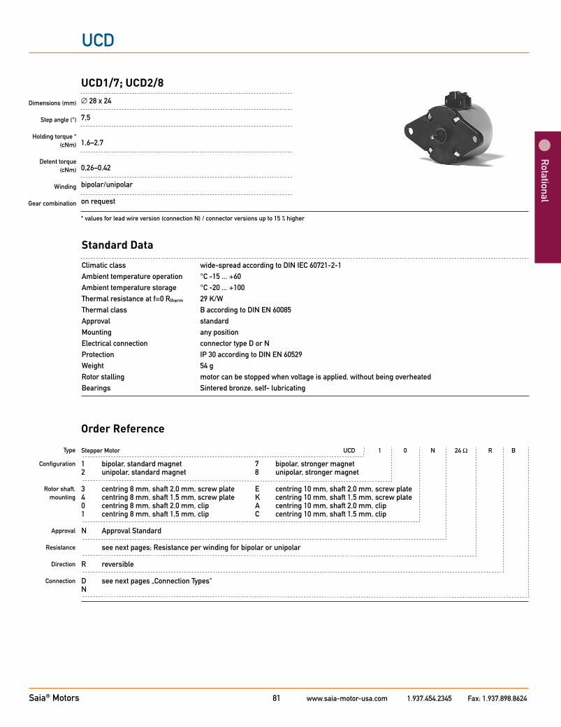
Stepper Motor UCD 1 0 N 24 Ω R B
1 bipolar, standard magnet 7 bipolar, stronger magnet2 unipolar, standard magnet 8 unipolar, stronger magnet
3 centring 8 mm, shaft 2,0 mm, screw plate E centring 10 mm, shaft 2,0 mm, screw plate4 centring 8 mm, shaft 1,5 mm, screw plate K centring 10 mm, shaft 1,5 mm, screw plate0 centring 8 mm, shaft 2,0 mm, clip A centring 10 mm, shaft 2,0 mm, clip1 centring 8 mm, shaft 1,5 mm, clip C centring 10 mm, shaft 1,5 mm, clip
N Approval Standard
see next pages; Resistance per winding for bipolar or unipolar
R reversible
D see next pages „Connection Types“N
Dimensions (mm)
Step angle (°)
Holding torque *(cNm)
Detent torque (cNm)
Winding
Gear combination
UCD1/7; UCD2/8 ∅ 28 x 24
7,5
1,6–2,7
0,26–0,42
bipolar/unipolar
on request
* values for lead wire version (connection N) / connector versions up to 15 % higher
Standard Data
Climatic class wide-spread according to DIN IEC 60721-2-1Ambient temperature operation °C -15 ... +60 Ambient temperature storage °C -20 ... +100Thermal resistance at f=0 Rtherm 29 K/W Thermal class B according to DIN EN 60085Approval standardMounting any positionElectrical connection connector type D or NProtection IP 30 according to DIN EN 60529Weight 54 g Rotor stalling motor can be stopped when voltage is applied, without being overheatedBearings Sintered bronze, self- lubricating
Type
Configuration
Rotor shaft, mounting
Approval
Resistance Direction
Connection
Order Reference
UCD

Saia® Motors www.saia-motor-usa.com 1.937.454.2345 Fax: 1.937.898.862482
UCD
Technical Data
bipolar UCD1 UCD5 Holding torque MH * cNm 2 2,7 Detent torque MS cNm 0,26 0,42 Rotor inertia JR gcm2 2,2 2,4
Rated voltage UN V 6 12 24 Resistance per winding R20 Ω 24 90 380 Steps per revolution 48 Duty cycle 100% Direction of rotation V reversible
unipolar UCD2 UCD6 Holding torque MH cNm 1,6 2,3 Detent torque MS cNm 0,26 0,42 Rotor inertia JR gcm2 2,2 2,4
Rated voltage UN V 3 6 24 Resistance per winding R20 Ω 24 90 380 Steps per revolution 48 Duty cycle 100% Direction of rotation V reversible
* values for lead wire version (connection N) / connector versions up to 15 % higher
Circuit diagram bipolar
unipolar
counter clockwise rotation
clockwise rotation
counter clockwise rotation
clockwise rotation
Rot
atio
nal

Saia® Motors www.saia-motor-usa.com 1.937.454.2345 Fax: 1.937.898.862483
Rotational
UCD
Dimensions Version with Connector D
Version with Connector N
D 8 mm 10 mm
D 8 mm 10 mm
6
1
4
3

Saia® Motors www.saia-motor-usa.com 1.937.454.2345 Fax: 1.937.898.862484
UCD
M/cNm UCD5 - Pull-out range P/W
2,5 1,25
2,0 1,00
1,5 0,75
1,0 0,5
0,5 0,25
0,0 0,00
0 100 200 300 400 500 600 700 fs/Hz
M/cNm UCD6 - Pull-in range P/W
2,0 1,00
1,8 0,90
1,6 0,80
1,4 0,70
1,2 0,60
1,0 0,50
0,8 0,40
0,6 0,30
0,4 0,20
0,2 0,10
0,0 0,00
0 50 100 150 200 250 300 350 400 fs/Hz
UCD6 - Pull-in range
0,0
0,2
0,4
0,6
0,8
1,0
1,2
1,4
1,6
1,8
2,0
0 50 100 150 200 250 300 350 400fS/ Hz
M/ cNm
0,00
0,10
0,20
0,30
0,40
0,50
0,60
0,70
0,80
0,90
1,00
M - ED 100 %
M - ED 30 %
P - ED 100 %
P - ED 30 %
P/ W
UCD6 - Pull-out range
0,0
0,2
0,4
0,6
0,8
1,0
1,2
1,4
1,6
1,8
2,0
0 100 200 300 400 500 600fS/ Hz
M/ cNm
0,00
0,10
0,20
0,30
0,40
0,50
0,60
0,70
0,80
0,90
1,00
M - ED 100 %
M - ED 30 %
P - ED 100 %
P - ED 30 %
P/ W
M/cNm UCD1 - Pull-out range P/W
2,0 0,50
1,8 0,45
1,6 0,40
1,4 0,35
1,2 0,30
1,0 0,25
0,8 0,20
0,6 0,15
0,4 0,10
0,2 0,05
0,0 0,00
0 100 200 300 400 500 600 fs/Hz
M/cNm UCD1 - Pull-in range P/W
2,0 0,50
1,8 0,45
1,6 0,40
1,4 0,35
1,2 0,30
1,0 0,25
0,8 0,20
0,6 0,15
0,4 0,10
0,2 0,05
0,0 0,00
0 50 100 150 200 250 300 350 400 450 fs/Hz
Performance Chart
M/cNm UCD2 - Pull-in range P/W
1,4 0,70
1,2 0,60
1,0 0,50
0,8 0,40
0,6 0,30
0,4 0,20
0,2 0,10
0,0 0,00
0 50 100 150 200 250 300 350 400 fs/Hz
M/cNm UCD2 - Pull-out range P/W
1,6 0,80
1,4 0,70
1,2 0,60
1,0 0,50
0,8 0,40
0,6 0,30
0,4 0,20
0,2 0,10
0,0 0,00
0 100 200 300 400 500 600 fs/Hz
M/cNm UCD5 - Pull-in range P/W
2,5 1,25
2,0 1,00
1,5 0,75
1,0 0,5
0,5 0,25
0,0 0,00
0 100 200 300 400 500 fs/Hz
M/cNm UCD6 - Pull-out range P/W
2,0 1,00
1,8 0,90
1,6 0,80
1,4 0,70
1,2 0,60
1,0 0,50
0,8 0,40
0,6 0,30
0,4 0,20
0,2 0,10
0,0 0,00
0 100 200 300 400 500 600 fs/Hz
UCD1 - Pull-in range
0
0,2
0,4
0,6
0,8
1
1,2
1,4
1,6
1,8
2
0 50 100 150 200 250 300 350 400 450fS/ Hz
M/ cNm
0,00
0,05
0,10
0,15
0,20
0,25
0,30
0,35
0,40
0,45
0,50
M - ED 100 %
M - ED 30 %
P - ED 100 %
P - ED 30 %
P/ W
UCD1 - Pull-out range
0,0
0,2
0,4
0,6
0,8
1,0
1,2
1,4
1,6
1,8
2,0
0 100 200 300 400 500 600fS/ Hz
M/ cNm
0,00
0,05
0,10
0,15
0,20
0,25
0,30
0,35
0,40
0,45
0,50
M - ED 100 %
M - ED 30 %
P - ED 100 %
P - ED 30 %
P/ W
UCD2 - Pull-in range
0,0
0,2
0,4
0,6
0,8
1,0
1,2
1,4
0 50 100 150 200 250 300 350 400fS/ Hz
M/ cNm
0,00
0,10
0,20
0,30
0,40
0,50
0,60
0,70
M - ED 100 %
M - ED 30 %
P - ED 100 %
P - ED 30 %
P/ W
UCD2 - Pull-out range
0,0
0,2
0,4
0,6
0,8
1,0
1,2
1,4
1,6
0 100 200 300 400 500 600fS/ Hz
M/ cNm
0,00
0,10
0,20
0,30
0,40
0,50
0,60
0,70
0,80
M - ED 100 %
M - ED 30 %
P - ED 100 %
P - ED 30 %
P/ W
UCD5 - Pull-in range
0,0
0,5
1,0
1,5
2,0
2,5
0 100 200 300 400 500fS/ Hz
M/ cNm
0,00
0,25
0,50
0,75
1,00
1,25
M - ED 100 %
M - ED 30 %
P - ED 100 %
P - ED 30 %
P/ W
UCD5 - Pull-out range
0,0
0,5
1,0
1,5
2,0
2,5
0 100 200 300 400 500 600 700fS/ Hz
M/ cNm
0,00
0,25
0,50
0,75
1,00
1,25
M - ED 100 %
M - ED 30 %
P - ED 100 %
P - ED 30 %
P/ W
UCD6 - Pull-in range
0,0
0,2
0,4
0,6
0,8
1,0
1,2
1,4
1,6
1,8
2,0
0 50 100 150 200 250 300 350 400fS/ Hz
M/ cNm
0,00
0,10
0,20
0,30
0,40
0,50
0,60
0,70
0,80
0,90
1,00
M - ED 100 %
M - ED 30 %
P - ED 100 %
P - ED 30 %
P/ W
UCD6 - Pull-out range
0,0
0,2
0,4
0,6
0,8
1,0
1,2
1,4
1,6
1,8
2,0
0 100 200 300 400 500 600fS/ Hz
M/ cNm
0,00
0,10
0,20
0,30
0,40
0,50
0,60
0,70
0,80
0,90
1,00
M - ED 100 %
M - ED 30 %
P - ED 100 %
P - ED 30 %
P/ W
M - Duty cycle 30 % P - Duty cycle 30 %M - Duty cycle 100% P - Duty cycle 100 %
Rot
atio
nal

Saia® Motors www.saia-motor-usa.com 1.937.454.2345 Fax: 1.937.898.862485
UCB
Rotational
Stepper Motor UCB 1 0 N 24 Ω R B
1 bipolar, standard magnet 7 bipolar, stronger magnet2 unipolar, standard magnet 8 unipolar, stronger magnet
3 centring 8 mm, shaft 2,0 mm, screw plate E centring 10 mm, shaft 2,0 mm, screw plate4 centring 8 mm, shaft 1,5 mm, screw plate K centring 10 mm, shaft 1,5 mm, screw plate0 centring 8 mm, shaft 2,0 mm, clip A centring 10 mm, shaft 2,0 mm, clip1 centring 8 mm, shaft 1,5 mm, clip C centring 10 mm, shaft 1,5 mm, clip
N Approval Standard
see next pages; Resistance per winding for bipolar or unipolar
R reversible
D see next pages „Connection Types“N
Dimensions (mm)
Step angle (°)
Holding torque * (cNm)
Detent torque (cNm)
Winding
Gear combination
UCB1/7; UCB2/8 ∅ 28 x 24
15
1,3–2,3
0,29
bipolar/unipolar
on request
* values for lead wire version (connection N) / connector versions up to 15 % higher
Standard Data
Climatic class wide-spread according to DIN IEC 60721-2-1Ambient temperature operation °C -15 ... +60 Ambient temperature storage °C -20 ... +100Thermal resistance at f=0 Rtherm 29 K/W Thermal class B according to DIN EN 60085Approval standardMounting any positionElectrical connection connector type D or NProtection IP 30 according to DIN EN 60529Weight 54 g Rotor stalling motor can be stopped when voltage is applied, without being overheatedBearings Sintered bronze, self- lubricating
Type
Configuration
Rotor shaft, mounting
Approval
Resistance
Direction
Connection
Order Reference
Saia® Motors www.saia-motor-usa.com 1.937.454.2345 Fax: 1.937.898.862486
UCB
Rot
atio
nal
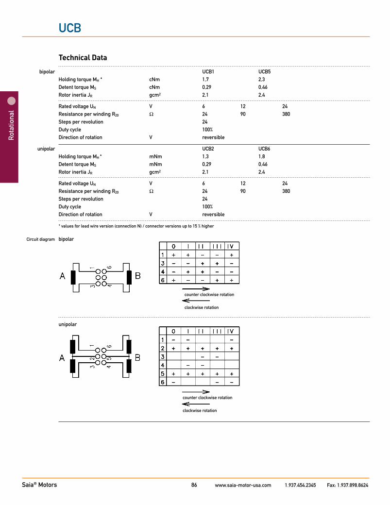
Technical Data
bipolar UCB1 UCB5 Holding torque MH * cNm 1,7 2,3 Detent torque MS cNm 0,29 0,46 Rotor inertia JR gcm2 2,1 2,4
Rated voltage UN V 6 12 24 Resistance per winding R20 Ω 24 90 380 Steps per revolution 24 Duty cycle 100% Direction of rotation V reversible
unipolar UCB2 UCB6 Holding torque MH * mNm 1,3 1,8 Detent torque MS mNm 0,29 0,46 Rotor inertia JR gcm2 2,1 2,4
Rated voltage UN V 6 12 24 Resistance per winding R20 Ω 24 90 380 Steps per revolution 24 Duty cycle 100% Direction of rotation V reversible
* values for lead wire version (connection N) / connector versions up to 15 % higher
Circuit diagram bipolar
unipolar
counter clockwise rotation
clockwise rotation
counter clockwise rotation
clockwise rotation
Saia® Motors www.saia-motor-usa.com 1.937.454.2345 Fax: 1.937.898.862487
UCB
Rotational
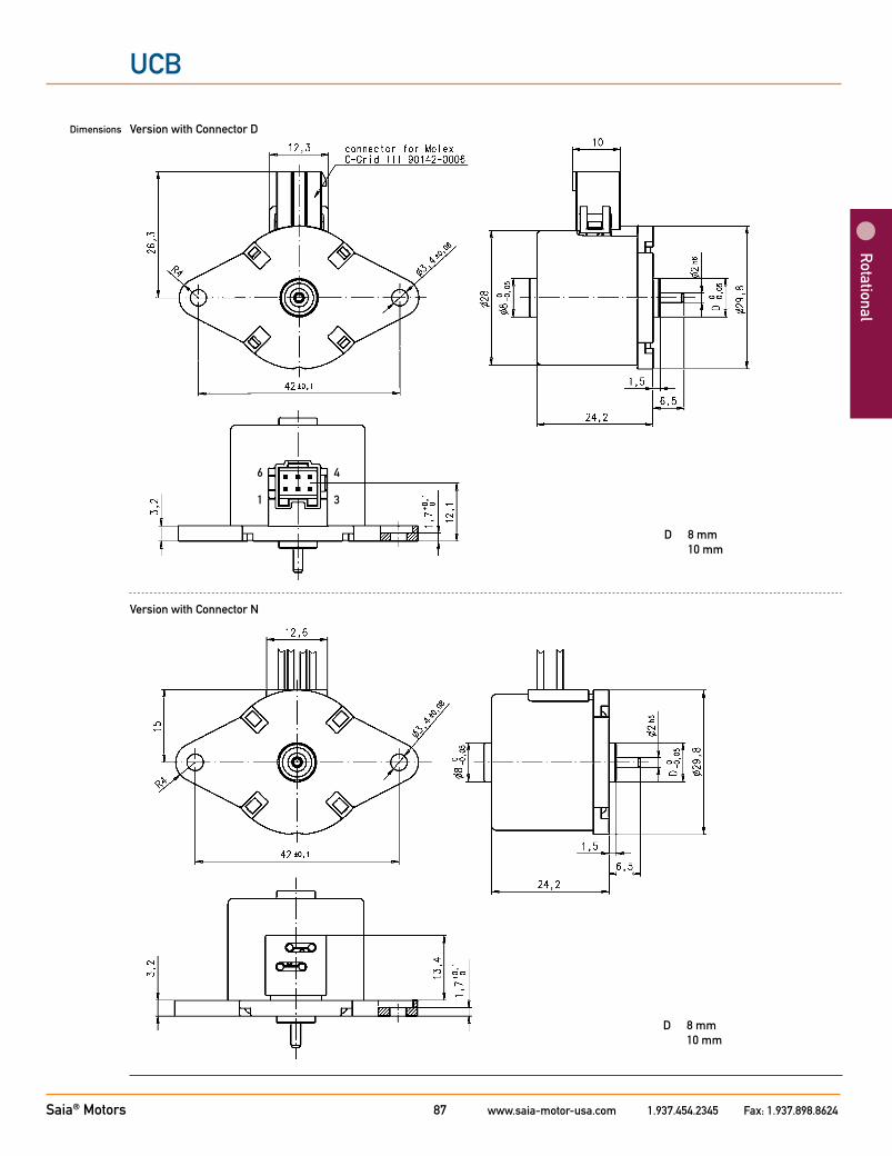
Dimensions Version with Connector D
Version with Connector N
D 8 mm 10 mm
D 8 mm 10 mm
6
1
4
3
Saia® Motors www.saia-motor-usa.com 1.937.454.2345 Fax: 1.937.898.862488
UCB
Rot
atio
nal
M/cNm UCB1 - Pull-out range P/W
1,8 0,90
1,6 0,80
1,4 0,70
1,2 0,60
1,0 0,50
0,8 0,40
0,6 0,30
0,4 0,20
0,2 0,10
0,0 0,00
0 100 200 300 400 500 600 fs/Hz
M/cNm UCB1 - Pull-in range P/W
1,6 0,80
1,4 0,70
1,2 0,60
1,0 0,50
0,8 0,40
0,6 0,30
0,4 0,20
0,2 0,10
0,0 0,00
0 50 100 150 200 250 300 350 fs/Hz
UCB1 - Pull-in range
0,0
0,2
0,4
0,6
0,8
1,0
1,2
1,4
1,6
0 50 100 150 200 250 300 350fS/ Hz
M/ cNm
0,00
0,10
0,20
0,30
0,40
0,50
0,60
0,70
0,80
M - ED 100 %
M - ED 30 %
P - ED 100 %
P - ED 30 %
P/ W
UCB1 - Pull-out range
0,0
0,2
0,4
0,6
0,8
1,0
1,2
1,4
1,6
1,8
0 100 200 300 400 500 600fS/ Hz
M/ cNm
0,00
0,10
0,20
0,30
0,40
0,50
0,60
0,70
0,80
0,90
M - ED 100 %
M - ED 30 %
P - ED 100 %
P - ED 30 %
P/ W
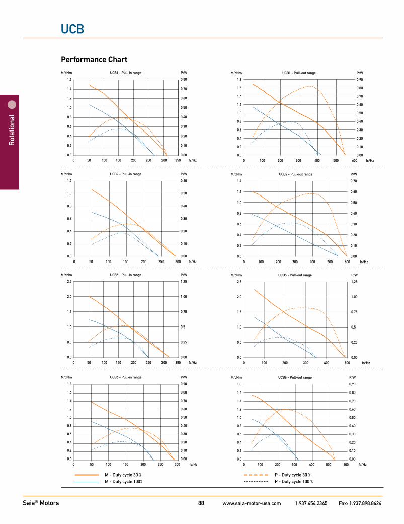
Performance Chart
UCB1 - Pull-in range
0,0
0,2
0,4
0,6
0,8
1,0
1,2
1,4
1,6
0 50 100 150 200 250 300 350fS/ Hz
M/ cNm
0,00
0,10
0,20
0,30
0,40
0,50
0,60
0,70
0,80
M - ED 100 %
M - ED 30 %
P - ED 100 %
P - ED 30 %
P/ W
UCB1 - Pull-out range
0,0
0,2
0,4
0,6
0,8
1,0
1,2
1,4
1,6
1,8
0 100 200 300 400 500 600fS/ Hz
M/ cNm
0,00
0,10
0,20
0,30
0,40
0,50
0,60
0,70
0,80
0,90
M - ED 100 %
M - ED 30 %
P - ED 100 %
P - ED 30 %
P/ W
M/cNm UCB2 - Pull-in range P/W
1,2 0,60
1,0 0,50
0,8 0,40
0,6 0,30
0,4 0,20
0,2 0,10
0,0 0,00
0 50 100 150 200 250 300 fs/Hz
M/cNm UCB2 - Pull-out range P/W
1,4 0,70
1,2 0,60
1,0 0,50
0,8 0,40
0,6 0,30
0,4 0,20
0,2 0,10
0,0 0,00
0 100 200 300 400 500 600 fs/Hz
M/cNm UCB5 - Pull-in range P/W
2,5 1,25
2,0 1,00
1,5 0,75
1,0 0,5
0,5 0,25
0,0 0,00
0 50 100 150 200 250 300 350 fs/Hz
M/cNm UCB5 - Pull-out range P/W
2,5 1,25
2,0 1,00
1,5 0,75
1,0 0,5
0,5 0,25
0,0 0,00
0 100 200 300 400 500 fs/Hz
M/cNm UCB6 - Pull-in range P/W
1,8 0,90
1,6 0,80
1,4 0,70
1,2 0,60
1,0 0,50
0,8 0,40
0,6 0,30
0,4 0,20
0,2 0,10
0,0 0,00
0 50 100 150 200 250 300 fs/Hz
M/cNm UCB6 - Pull-out range P/W
1,8 0,90
1,6 0,80
1,4 0,70
1,2 0,60
1,0 0,50
0,8 0,40
0,6 0,30
0,4 0,20
0,2 0,10
0,0 0,00
0 100 200 300 400 500 600 fs/Hz
0,0
0,5
1,0
1,5
2,0
2,5
0 50 100 150 200 250 300 350fS/ Hz
M/ cNm
0,00
0,25
0,50
0,75
1,00
1,25
M - ED 100 %
M - ED 30 %
P - ED 100 %
P - ED 30 %
P/ W
0,0
0,5
1,0
1,5
2,0
2,5
0 100 200 300 400 500fS/ Hz
M/ cNm
0,00
0,25
0,50
0,75
1,00
1,25
M - ED 100 %
M - ED 30 %
P - ED 100 %
P - ED 30 %
P/ W
0,0
0,5
1,0
1,5
2,0
2,5
0 50 100 150 200 250 300 350fS/ Hz
M/ cNm
0,00
0,25
0,50
0,75
1,00
1,25
M - ED 100 %
M - ED 30 %
P - ED 100 %
P - ED 30 %
P/ W
0,0
0,5
1,0
1,5
2,0
2,5
0 100 200 300 400 500fS/ Hz
M/ cNm
0,00
0,25
0,50
0,75
1,00
1,25
M - ED 100 %
M - ED 30 %
P - ED 100 %
P - ED 30 %
P/ W
UCB2 - Pull-in range
0,0
0,2
0,4
0,6
0,8
1,0
1,2
0 50 100 150 200 250 300fS/ Hz
M/ cNm
0,00
0,10
0,20
0,30
0,40
0,50
0,60
M - ED 100 %
M - ED 30 %
P - ED 100 %
P - ED 30 %
P/ W
UCB2 - Pull-out range
0,0
0,2
0,4
0,6
0,8
1,0
1,2
1,4
0 100 200 300 400 500 600fS/ Hz
M/ cNm
0,00
0,10
0,20
0,30
0,40
0,50
0,60
0,70
M - ED 100 %
M - ED 30 %
P - ED 100 %
P - ED 30 %
P/ W
UCB6 - Pull-in range
0
0,2
0,4
0,6
0,8
1
1,2
1,4
1,6
1,8
0 50 100 150 200 250 300fS/ Hz
M/ cNm
0,00
0,10
0,20
0,30
0,40
0,50
0,60
0,70
0,80
0,90
M - ED 100 %
M - ED 30 %
P - ED 100 %
P - ED 30 %
P/ W
UCB6 - Pull-out range
0,0
0,2
0,4
0,6
0,8
1,0
1,2
1,4
1,6
1,8
0 100 200 300 400 500 600fS/ Hz
M/ cNm
0,00
0,10
0,20
0,30
0,40
0,50
0,60
0,70
0,80
0,90
M - ED 100 %
M - ED 30 %
P - ED 100 %
P - ED 30 %
P/ W
M - Duty cycle 30 % P - Duty cycle 30 %M - Duty cycle 100% P - Duty cycle 100 %

Saia® Motors www.saia-motor-usa.com 1.937.454.2345 Fax: 1.937.898.862489
UBD
Rotational
Type
Configuration
Rotor shaft, mounting
Approval
Resistance
Direction
Cable
Stepper Motor UBD 1 0 N 18,5 R E
1 bipolar, standard magnet 5 bipolar, stronger magnet 2 unipolar, standard magnet 6 unipolar, stronger magnet
0 centring 8 mm, shaft 2,0 mm, clip A centring 10 mm, shaft 2,0 mm, clip 1 centring 8 mm, shaft 1,5 mm, clip C centring 10 mm, shaft 1,5 mm, clip 3 centring 8 mm, shaft 2,0 mm, screw plate E centring 10 mm, shaft 2,0 mm, screw plate 4 centring 8 mm, shaft 1,5 mm, screw plate K centring 10 mm, shaft 1,5 mm, screw plate
N Approval Standard
See next page Resistance per winding for bipolar or unipolar.
reversible
E cable 150 mm (other on request)
Standard Data
Climatic class wide-spread according to DIN IEC 60721-2-1
Ambient temperature operation °C -15...+55 Ambient temperature storage °C -20...+100 Thermal resistance at f=0 Rtherm 27 K/W
Thermal class A according to DIN EN 60085
Approval standard (UL/CSA on request)
Mounting any position
Electrical connection cable
Protection IP 40 according to DIN EN 60529
Weight 60 g
Rotor stalling motor can be stopped when voltage is applied, without being overheated
Bearings sintered bronze, self-lubricating
Electric strength according to DIN EN 60034-1/DIN EN 60335-1
Order Reference
Dimensions (mm)
Step angle (°)
Holding torque (cNm)
Detent torque (cNm)
Winding
Gear combination
UBD1/2/5/6 ∅ 36 x 21
7.5
1.3–1.9
0.22/0.27
bipolar/unipolar
A, D, M, B, F, V

Saia® Motors www.saia-motor-usa.com 1.937.454.2345 Fax: 1.937.898.862490
UBD
Rot
atio
nal
Technical Data
bipolar (UBD1/5) Rated voltage UN V 3 6 12 24
Resistance per winding R20 Ω 11,5 18,5 100 460
Holding torque MH cNm 1,8 (UBD1); 1,9 (UBD5)
Detent torque MS cNm 0,22 (UBD1); 0,27 (UBD5)
Rotor inertia JR gcm2 2,8 (UBD 1), 2,9 (UBD 5)
unipolar (UBD2/6) Rated voltage UN V 3 6 12 24
Resistance per winding R20 Ω 12 28 120 500
Holding torque MH cNm 1,3 (UBD2); 1,6 (UBD6)
Detent torque MS cNm 0,22 (UBD2); 0,27 (UBD6)
Rotor inertia JR gcm2 2,8 (UBD2); 2,9 (UBD6)
Steps per revolution 48
Winding temperature Tmax 105° C
Duty cycle 100%
Direction of rotation reversible
Dimensions
ø8
0 -0,0
5
øD
øZ
0 -0,0
5
ø 36
1,5
6,15
42±0
,05
3,6
±0,0
5
48
1,56,5
21±0,2
0,8
øY
min. 8
5 +0-0,1
52,5
±0,5
48+0 -0
,5
max.25,3
Plate cut-out
0,4
1...1,8
max. 2,3
Mounting with snap on clipMounting with screw plate
48
ø36
42±0
,05
3,2
+0,1
-0
10°
6,86
Mounting with screw plate
FF
Saia® Motors www.saia-motor-usa.com 1.937.454.2345 Fax: 1.937.898.862491
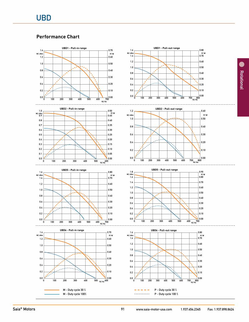
UBD
Rotational
Performance Chart
0.0
0.2
0.4
0.6
0.8
1.0
1.2
1.4
0 100 200 300 400 500 600 700fS/ Hz
M/ cNm
0.00
0.10
0.20
0.30
0.40
0.50
0.60
0.70P/ W
UBD1 - Pull-in range
UBD1 - Pull-out range
0.0
0.2
0.4
0.6
0.8
1.0
1.2
1.4
1.6
0 100 200 300 400 500 600 700 800fS/ Hz
M/ cNm
0.00
0.10
0.20
0.30
0.40
0.50
0.60
0.70
0.80P/ W
0.0
0.2
0.4
0.6
0.8
1.0
1.2
1.4
0 100 200 300 400 500 600 700fS/ Hz
M/ cNm
0.00
0.10
0.20
0.30
0.40
0.50
0.60
0.70P/ W
UBD1 - Pull-in range
UBD1 - Pull-out range
0.0
0.2
0.4
0.6
0.8
1.0
1.2
1.4
1.6
0 100 200 300 400 500 600 700 800fS/ Hz
M/ cNm
0.00
0.10
0.20
0.30
0.40
0.50
0.60
0.70
0.80P/ W
UBD2 - Pull-in range
0.0
0.1
0.2
0.3
0.4
0.5
0.6
0.7
0.8
0.9
1.0
0 100 200 300 400 500 600fS/ Hz
M/ cNm
0.00
0.05
0.10
0.15
0.20
0.25
0.30
0.35
0.40
0.45
0.50P/ W
0.0
0.2
0.4
0.6
0.8
1.0
1.2
0 100 200 300 400 500 600 700 800fS/ Hz
M/ cNm
0.00
0.10
0.20
0.30
0.40
0.50
0.60
P/ W
UBD2 - Pull-out range
UBD2 - Pull-in range
0.0
0.1
0.2
0.3
0.4
0.5
0.6
0.7
0.8
0.9
1.0
0 100 200 300 400 500 600fS/ Hz
M/ cNm
0.00
0.05
0.10
0.15
0.20
0.25
0.30
0.35
0.40
0.45
0.50P/ W
0.0
0.2
0.4
0.6
0.8
1.0
1.2
0 100 200 300 400 500 600 700 800fS/ Hz
M/ cNm
0.00
0.10
0.20
0.30
0.40
0.50
0.60
P/ W
UBD2 - Pull-out range
100 200 300 400 500 600 700fS/ Hz
0.00
0.10
0.20
0.30
0.40
0.50
0.60
0.70
0.80P/ W
UBD5 - Pull-in range
0.0
0.2
0.4
0.6
0.8
1.0
1.2
1.4
1.6
0
M/ cNm
0.0
0.2
0.4
0.6
0.8
1.0
1.2
1.4
1.6
1.8
0 100 200 300 400 500 600fS/ Hz
M/ cNm
UBD5 - Pull-out range
7000.00
0.10
0.20
0.30
0.40
0.50
0.60
0.70
0.80
0.90P/ W
UBD6 - Pull-in range
100 200 300 400 500 600fS/ Hz
0.00
0.10
0.20
0.30
0.40
0.50
0.60
0.70P/ W
0.0
0.2
0.4
0.6
0.8
1.0
1.2
1.4
0
M/ cNm
UBD6 - Pull-out range
0.0
0.2
0.4
0.6
0.8
1.0
1.2
1.4
1.6
0 100 200 300 400 500 600 700 800fS/ Hz
M/ cNm
0.00
0.10
0.20
0.30
0.40
0.50
0.60
0.70
0.80P/ W
UBD6 - Pull-in range
100 200 300 400 500 600fS/ Hz
0.00
0.10
0.20
0.30
0.40
0.50
0.60
0.70P/ W
0.0
0.2
0.4
0.6
0.8
1.0
1.2
1.4
0
M/ cNm
UBD6 - Pull-out range
0.0
0.2
0.4
0.6
0.8
1.0
1.2
1.4
1.6
0 100 200 300 400 500 600 700 800fS/ Hz
M/ cNm
0.00
0.10
0.20
0.30
0.40
0.50
0.60
0.70
0.80P/ W
M - Duty cycle 30 % P - Duty cycle 30 %M - Duty cycle 100% P - Duty cycle 100 %
Saia® Motors www.saia-motor-usa.com 1.937.454.2345 Fax: 1.937.898.862492
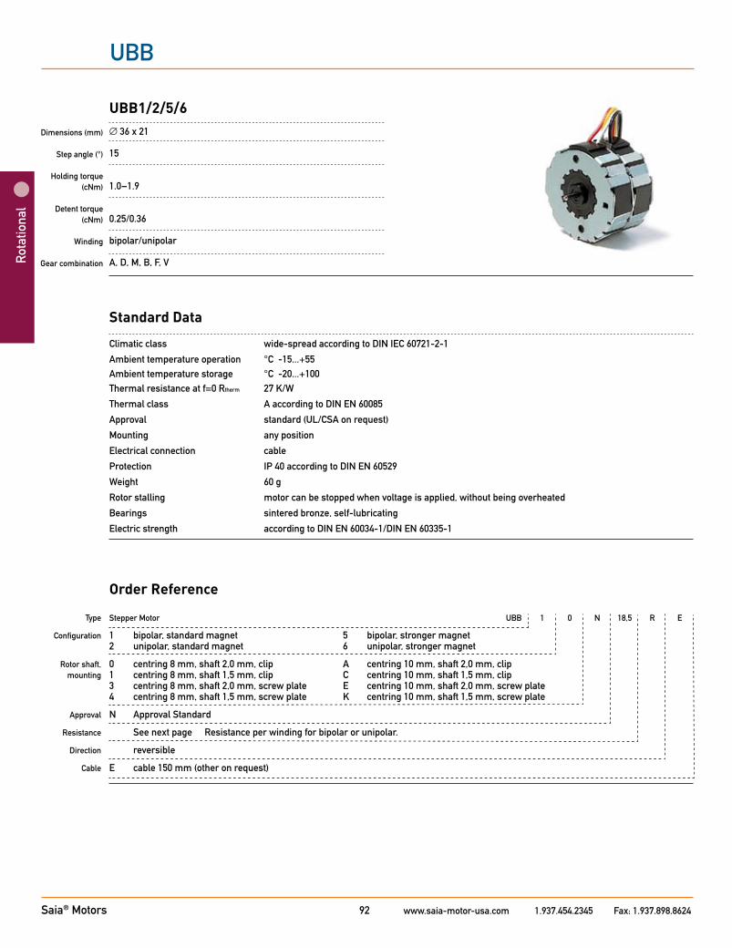
UBB
Rot
atio
nal
Standard Data
Climatic class wide-spread according to DIN IEC 60721-2-1
Ambient temperature operation °C -15...+55 Ambient temperature storage °C -20...+100 Thermal resistance at f=0 Rtherm 27 K/W
Thermal class A according to DIN EN 60085
Approval standard (UL/CSA on request)
Mounting any position
Electrical connection cable
Protection IP 40 according to DIN EN 60529
Weight 60 g
Rotor stalling motor can be stopped when voltage is applied, without being overheated
Bearings sintered bronze, self-lubricating
Electric strength according to DIN EN 60034-1/DIN EN 60335-1
Type
Configuration
Rotor shaft, mounting
Approval
Resistance
Direction
Cable
Stepper Motor UBB 1 0 N 18,5 R E
1 bipolar, standard magnet 5 bipolar, stronger magnet 2 unipolar, standard magnet 6 unipolar, stronger magnet
0 centring 8 mm, shaft 2,0 mm, clip A centring 10 mm, shaft 2,0 mm, clip 1 centring 8 mm, shaft 1,5 mm, clip C centring 10 mm, shaft 1,5 mm, clip 3 centring 8 mm, shaft 2,0 mm, screw plate E centring 10 mm, shaft 2,0 mm, screw plate 4 centring 8 mm, shaft 1,5 mm, screw plate K centring 10 mm, shaft 1,5 mm, screw plate
N Approval Standard
See next page Resistance per winding for bipolar or unipolar.
reversible
E cable 150 mm (other on request)
Order Reference
Dimensions (mm)
Step angle (°)
Holding torque (cNm)
Detent torque(cNm)
Winding
Gear combination
UBB1/2/5/6 ∅ 36 x 21
15
1.0–1.9
0.25/0.36
bipolar/unipolar
A, D, M, B, F, V
Saia® Motors www.saia-motor-usa.com 1.937.454.2345 Fax: 1.937.898.862493
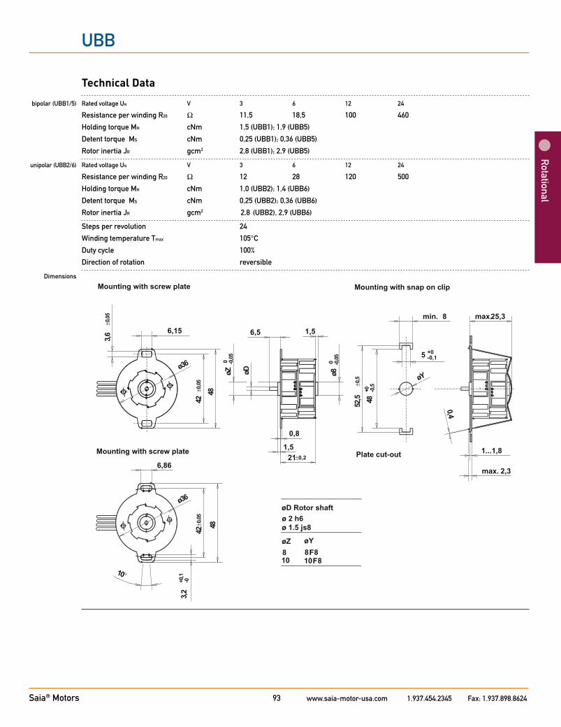
UBB
Rotational
Technical Data
bipolar (UBB1/5) Rated voltage UN V 3 6 12 24
Resistance per winding R20 Ω 11,5 18,5 100 460
Holding torque MH cNm 1,5 (UBB1); 1,9 (UBB5)
Detent torque MS cNm 0,25 (UBB1); 0,36 (UBB5)
Rotor inertia JR gcm2 2,8 (UBB1); 2,9 (UBB5)
unipolar (UBB2/6) Rated voltage UN V 3 6 12 24
Resistance per winding R20 Ω 12 28 120 500
Holding torque MH cNm 1,0 (UBB2); 1,4 (UBB6)
Detent torque MS cNm 0,25 (UBB2); 0,36 (UBB6)
Rotor inertia JR gcm2 2,8 (UBB2), 2,9 (UBB6)
Steps per revolution 24
Winding temperature Tmax 105°C
Duty cycle 100%
Direction of rotation reversible
Dimensions
ø8
0 -0,0
5
øD
øZ
0 -0,0
5
ø 36
1,5
6,15
42±0
,05
3,6
±0,0
5
48
1,56,5
21±0,2
0,8
øY
min. 8
5 +0-0,1
52,5
±0,5
48+0 -0
,5
max.25,3
Plate cut-out
0,4
1...1,8
max. 2,3
Mounting with snap on clipMounting with screw plate
48
ø 36
42±0
,05
3,2
+0,1
-0
10°
6,86
Mounting with screw plate
FF

Saia® Motors www.saia-motor-usa.com 1.937.454.2345 Fax: 1.937.898.862494
UBB
Rot
atio
nal
Performance Chart
0.0
0.2
0.4
0.6
0.8
1.0
1.2
1.4M/ cNm
0.0
0.2
0.4
0.6
0.8
1.0
1.2
1.4M/ cNm
UBB1 - Pull-in range
UBB1 - Pull-out range
0.00
0.10
0.20
0.30
0.40
0.50
0.60
0.70P/ W
0 50 100 150 200 250 300 350 400 450 500fS/ Hz
8000.00
0.10
0.20
0.30
0.40
0.50
0.60
0.70P/ W
0 100 200 300 400 500 600 700fS/ Hz
0.0
0.2
0.4
0.6
0.8
1.0
1.2
1.4M/ cNm
0.0
0.2
0.4
0.6
0.8
1.0
1.2
1.4M/ cNm
UBB1 - Pull-in range
UBB1 - Pull-out range
0.00
0.10
0.20
0.30
0.40
0.50
0.60
0.70P/ W
0 50 100 150 200 250 300 350 400 450 500fS/ Hz
8000.00
0.10
0.20
0.30
0.40
0.50
0.60
0.70P/ W
0 100 200 300 400 500 600 700fS/ Hz
0.0
0.2
0.4
0.6
0.8
1.0
1.2
M/ cNm
0 50 100 150 200 250 300 350 400 450 500fS/ Hz
0.00
0.10
0.20
0.30
0.40
0.50
0.60P/ W
UBB2 - Pull-in range
0.00
0.20
0.40
0.60
0.80
1.00
1.20
P/ W
0 100 200 300 400 500 600 700 800fS/ Hz
0.0
0.2
0.4
0.6
0.8
1.0
1.2
M/ cNm
UBB2 - Pull-out range
0.0
0.2
0.4
0.6
0.8
1.0
1.2
M/ cNm
0 50 100 150 200 250 300 350 400 450 500fS/ Hz
0.00
0.10
0.20
0.30
0.40
0.50
0.60P/ W
UBB2 - Pull-in range
0.00
0.20
0.40
0.60
0.80
1.00
1.20
P/ W
0 100 200 300 400 500 600 700 800fS/ Hz
0.0
0.2
0.4
0.6
0.8
1.0
1.2
M/ cNm
UBB2 - Pull-out range
UBB5 - Pull-in range
0.0
0.2
0.4
0.6
0.8
1.0
1.2
1.4
1.6
1.8
2.0
0 50 100 150 200 250 300 350 400fS/ Hz
M/ cNm
0.00
0.10
0.20
0.30
0.40
0.50
0.60
0.70
0.80
0.90
1.00P/ W
UBB5 - Pull-out range
0.0
0.5
1.0
1.5
2.0
2.5
0 100 200 300 400 500 600 700fS/ Hz
M/ cNm
0.00
0.25
0.50
0.75
1.00
1.25
P/ W
UBB5 - Pull-in range
0.0
0.2
0.4
0.6
0.8
1.0
1.2
1.4
1.6
1.8
2.0
0 50 100 150 200 250 300 350 400fS/ Hz
M/ cNm
0.00
0.10
0.20
0.30
0.40
0.50
0.60
0.70
0.80
0.90
1.00P/ W
UBB5 - Pull-out range
0.0
0.5
1.0
1.5
2.0
2.5
0 100 200 300 400 500 600 700fS/ Hz
M/ cNm
0.00
0.25
0.50
0.75
1.00
1.25
P/ W
400 500 600 700 800fS/ Hz
0.00
0.10
0.20
0.30
0.40
0.50
0.60
0.70
0.80
0.90P/ W
0.0
0.2
0.4
0.6
0.8
1.0
1.2
1.4
1.6
1.8
0 100 200 300
M/ cNm
UBB6 - Pull-out range
UBB6 - Pull-in range
500fS/ Hz
0.00
0.10
0.20
0.30
0.40
0.50
0.60
0.70P/ W
0 50 100 150 200 250 300 350 400 4500.0
0.2
0.4
0.6
0.8
1.0
1.2
1.4M/ cNm
M - Duty cycle 30 % P - Duty cycle 30 %M - Duty cycle 100% P - Duty cycle 100 %

Saia® Motors www.saia-motor-usa.com 1.937.454.2345 Fax: 1.937.898.862495
UDB
Rotational
Standard Data
Climatic class wide-spread according to DIN IEC 60721-2-1
Ambient temperature operation °C -15...+60 Ambient temperature storage °C -20...+100 Thermal resistance at f=0 Rtherm 18 K/W
Thermal class A according to DIN EN 60085
Approval standard
Mounting any position
Electrical connection cable
Protection IP 40 according to DIN EN 60529
Weight 132 g
Rotor stalling motor can be stopped when voltage is applied, without being overheated
Bearings sintered bronze, self-lubricating
Electric strength according to DIN EN 60034-1/DIN EN 60335-1
Type
Configuration
Rotor shaft, mounting
Approval
Resistance
Direction
Cable
Stepper Motor UDB 1 0 N 78 R N
1 bipolar 2 unipolar
0 centring 8 mm, shaft 1,5 mm, clip 1 centring 8 mm, shaft 2,0 mm, clip
N Approval Standard
See next page Resistance per winding for bipolar or unipolar.
reversible
N cable 150 mm (other on request)
Order Reference
Dimensions (mm)
Step angle (°)
Holding torque (cNm)
Detent torque (cNm)
Winding
Gear combination
UDB1/2∅ 48 x 24
15
2,7/2,2
0.35
bipolar/unipolar
A, D, M, B, F, V, J

Saia® Motors www.saia-motor-usa.com 1.937.454.2345 Fax: 1.937.898.862496
UDB
Rot
atio
nal
Technical Data
bipolar (UDB1) Rated voltage UN V 6 12 24
Resistance per winding R20 Ω 15 78 350
Holding torque MH cNm 2,7
Detent torque MS cNm 0,35
Rotor inertia JR gcm2 6,3
unipolar (UDB2) Rated voltage UN V 6 12 24
Resistance per winding R20 Ω 19 75 300 Holding torque MH cNm 2,2
Detent torque MS cNm 0,35
Rotor inertia JR gcm2 6,3
Steps per revolution 24
Winding temperature Tmax 105° C
Duty cycle 100%
Direction of rotation reversible
Dimensions
+0,03
5+0
,013
+0,007- 0,007
0-0,006

Saia® Motors www.saia-motor-usa.com 1.937.454.2345 Fax: 1.937.898.862497
UDB
Rotational
Performance Chart
UDB1 - Pull-in range
0.0
0.5
1.0
1.5
2.0
2.5
3.0
0 50 100 150 200 250 300 350 400fS/ Hz
M/ cNm
0.00
0.25
0.50
0.75
1.00
1.25
1.50
P/ W
UDB1 - Pull-out range
0.0
0.5
1.0
1.5
2.0
2.5
3.0
3.5
0 50 100 150 200 250 300 350 400 450 500fS/ Hz
M/ cNm
0.00
0.25
0.50
0.75
1.00
1.25
1.50
1.75P/ W
UDB1 - Pull-in range
0.0
0.5
1.0
1.5
2.0
2.5
3.0
0 50 100 150 200 250 300 350 400fS/ Hz
M/ cNm
0.00
0.25
0.50
0.75
1.00
1.25
1.50
P/ W
UDB1 - Pull-out range
0.0
0.5
1.0
1.5
2.0
2.5
3.0
3.5
0 50 100 150 200 250 300 350 400 450 500fS/ Hz
M/ cNm
0.00
0.25
0.50
0.75
1.00
1.25
1.50
1.75P/ W
UDB2 - Pull-in range
0.0
0.5
1.0
1.5
2.0
2.5
0 50 100 150 200 250 300 350 400fS/ Hz
M/ cNm
0.00
0.20
0.40
0.60
0.80
1.00
P/ W
UDB2 - Pull-out range
0.0
0.5
1.0
1.5
2.0
2.5
3.0
0 100 200 300 400 500 600fS/ Hz
M/ cNm
0.00
0.25
0.50
0.75
1.00
1.25
1.50
P/ W
UDB2 - Pull-in range
0.0
0.5
1.0
1.5
2.0
2.5
0 50 100 150 200 250 300 350 400fS/ Hz
M/ cNm
0.00
0.20
0.40
0.60
0.80
1.00
P/ W
UDB2 - Pull-out range
0.0
0.5
1.0
1.5
2.0
2.5
3.0
0 100 200 300 400 500 600fS/ Hz
M/ cNm
0.00
0.25
0.50
0.75
1.00
1.25
1.50
P/ W
M - Duty cycle 30 % P - Duty cycle 30 %M - Duty cycle 100% P - Duty cycle 100 %

Saia® Motors www.saia-motor-usa.com 1.937.454.2345 Fax: 1.937.898.862498
UO
Rot
atio
nal
Stepper Motor ST5021 / ST5022 7,5° 7 Ω
7,5°11,25°
7 Ω
Dimensions (mm)
Step angle (°)
Holding torque (cNm)
Detent torque (cNm)
Winding
Gear combination
UO (ST5021; ST5022)∅ 50 x 21
7,5/11,25
3,7–4 (ST5021); 4 (ST5022)
0,25 (ST5021); 1 (ST5022)
bipolar
O, P, R
Standard Data
Climatic class wide-spread according to DIN IEC 60721-2-1Ambient temperature operation °C -15 ... +40 Ambient temperature storage °C -20 ... +100 Thermal class B (ST5021); A (ST5022) according to DIN EN 60085Approval standardMounting any positionElectrical connection cableProtection IP 30 according to DIN EN 60529Weight 180 g (ST5021); 195 g (ST5022)Rotor stalling motor can be stopped when voltage is applied, without being overheatedBearings Sintered bronze, self- lubricating
Type
Step angle
Resistance
Order Reference

Saia® Motors www.saia-motor-usa.com 1.937.454.2345 Fax: 1.937.898.862499
UO
Rotational
Technical Data
ST5021 Step angle ° 7,5 11,25 Rated voltage UN V 4 4 Holding torque MH cNm 4 3,7 Detent torque Ms cNm 0,25 Rotor inertia JR gcm2 14,5
Winding temperature increase K 65 Current per winding A 0,53 Resistance per winding R20 Ω 7 Inductance per winding mH 12,5 11,5 Power consumption W 4 Driver mode Chopper drive
ST5022 Step angle ° 7,5/11,25 Rated voltage UN V 4 Holding torque MH cNm 7,5 Detent torque Ms cNm 1 Rotor inertia JR gcm2 25
Winding temperature increase K 65 Current per winding A 0,53 Resistance per winding R20 Ω 7 Inductance per winding mH 11 Power consumption W 4 Driver mode Chopper drive
Circuit diagram Motor connections - bipolar
A
B
A
A1yellow
A2blue
B1red
B2grey
A1A2
B1B2
B
clockwise rotation

Saia® Motors www.saia-motor-usa.com 1.937.454.2345 Fax: 1.937.898.8624100
UO
Rot
atio
nal
ST5022 UOD5 (ST 5022/7,5/1) UOJ5 (ST 5022/11,25/1)
M/cNm M/cNm
fs/Hz fs/Hz
Dimensions
Standard - wire length: 100 mmGeneral tolerances acc. to DIN ISO 2768-mk
Performance Chart (chopper driver)
ST5021 UOD1 (ST 5021/7,5/1) UOJ1 (ST 5021/11,25/1)
M/cNm M/cNm
fs/Hz fs/Hz
Saia® Motors www.saia-motor-usa.com 1.937.454.2345 Fax: 1.937.898.8624101
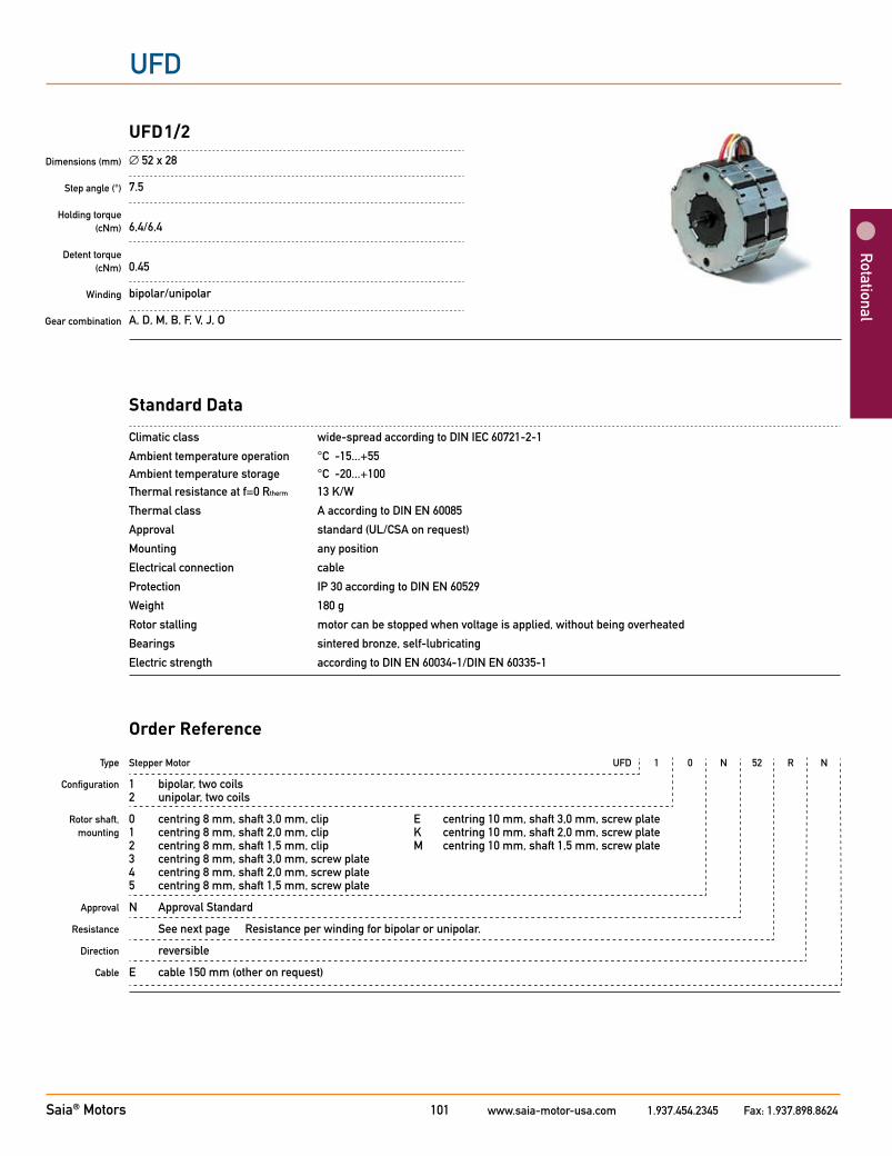
UFD
Rotational
Standard Data
Climatic class wide-spread according to DIN IEC 60721-2-1
Ambient temperature operation °C -15...+55 Ambient temperature storage °C -20...+100 Thermal resistance at f=0 Rtherm 13 K/W
Thermal class A according to DIN EN 60085
Approval standard (UL/CSA on request)
Mounting any position
Electrical connection cable
Protection IP 30 according to DIN EN 60529
Weight 180 g
Rotor stalling motor can be stopped when voltage is applied, without being overheated
Bearings sintered bronze, self-lubricating
Electric strength according to DIN EN 60034-1/DIN EN 60335-1
Type
Configuration
Rotor shaft, mounting
Approval
Resistance
Direction
Cable
Stepper Motor UFD 1 0 N 52 R N
1 bipolar, two coils 2 unipolar, two coils
0 centring 8 mm, shaft 3,0 mm, clip E centring 10 mm, shaft 3,0 mm, screw plate 1 centring 8 mm, shaft 2,0 mm, clip K centring 10 mm, shaft 2,0 mm, screw plate 2 centring 8 mm, shaft 1,5 mm, clip M centring 10 mm, shaft 1,5 mm, screw plate 3 centring 8 mm, shaft 3,0 mm, screw plate 4 centring 8 mm, shaft 2,0 mm, screw plate 5 centring 8 mm, shaft 1,5 mm, screw plate
N Approval Standard
See next page Resistance per winding for bipolar or unipolar.
reversible
E cable 150 mm (other on request)
Order Reference
Dimensions (mm)
Step angle (°)
Holding torque (cNm)
Detent torque (cNm)
Winding
Gear combination
UFD1/2∅ 52 x 28
7.5
6,4/6,4
0.45
bipolar/unipolar
A, D, M, B, F, V, J, O
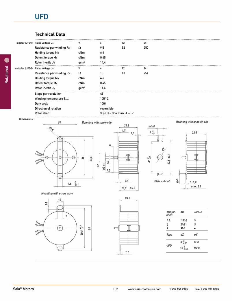
Saia® Motors www.saia-motor-usa.com 1.937.454.2345 Fax: 1.937.898.8624102
UFD
Rot
atio
nal
Technical Data
bipolar (UFD1) Rated voltage UN V 6 12 24
Resistance per winding R20 Ω 9,5 52 250
Holding torque MH cNm 6,4
Detent torque MS cNm 0,45
Rotor inertia JR gcm2 14,4
unipolar (UFD2) Rated voltage UN V 6 12 24
Resistance per winding R20 Ω 15 61 251
Holding torque MH cNm 4,6
Detent torque MS cNm 0,45
Rotor inertia JR gcm2 14,4
Steps per revolution 48
Winding temperature Tmax 105° C
Duty cycle 100%
Direction of rotation reversible Rotor shaft 3, D = 3h6, Dim. A = „-”
Dimensions
FF
F

Saia® Motors www.saia-motor-usa.com 1.937.454.2345 Fax: 1.937.898.8624103
UFD
Rotational
Performance Chart
UFD1 - Pull-in range
0
1
2
3
4
5
6
7
0 50 100 150 200 250 300 350 400fS/ Hz
M/ cNm
0.0
0.2
0.4
0.6
0.8
1.0
1.2
1.4P/ W
UFD1 - Pull-out range
0
1
2
3
4
5
6
7
8
0 100 200 300 400 500 600 700fS/ Hz
M/ cNm
0.0
0.2
0.4
0.6
0.8
1.0
1.2
1.4
1.6P/ W
UFD1 - Pull-in range
0
1
2
3
4
5
6
7
0 50 100 150 200 250 300 350 400fS/ Hz
M/ cNm
0.0
0.2
0.4
0.6
0.8
1.0
1.2
1.4P/ W
UFD1 - Pull-out range
0
1
2
3
4
5
6
7
8
0 100 200 300 400 500 600 700fS/ Hz
M/ cNm
0.0
0.2
0.4
0.6
0.8
1.0
1.2
1.4
1.6P/ W
UFD2 - Pull-in range
0
1
2
3
4
5
6
0 50 100 150 200 250 300 350 400 450 500fS/ Hz
M/ cNm
0.0
0.2
0.4
0.6
0.8
1.0
1.2
P/ W
UFD2 - Pull-out range
0
1
2
3
4
5
6
7
0 100 200 300 400 500 600 700 800fS/ Hz
M/ cNm
0.0
0.2
0.4
0.6
0.8
1.0
1.2
1.4P/ W
UFD2 - Pull-in range
0
1
2
3
4
5
6
0 50 100 150 200 250 300 350 400 450 500fS/ Hz
M/ cNm
0.0
0.2
0.4
0.6
0.8
1.0
1.2
P/ W
UFD2 - Pull-out range
0
1
2
3
4
5
6
7
0 100 200 300 400 500 600 700 800fS/ Hz
M/ cNm
0.0
0.2
0.4
0.6
0.8
1.0
1.2
1.4P/ W
M - Duty cycle 30 % P - Duty cycle 30 %M - Duty cycle 100% P - Duty cycle 100 %

Saia® Motors www.saia-motor-usa.com 1.937.454.2345 Fax: 1.937.898.8624104
UFB
Rot
atio
nal
Type
Configuration
Rotor shaft, mounting
Approval
Resistance
Direction
Cable
Standard Data
Climatic class wide-spread according to DIN IEC 60721-2-1
Ambient temperature operation °C -15...+55 Ambient temperature storage °C -20...+100 Thermal resistance at f=0 Rtherm 11 K/W (UFB1/2), 7 K/W (UFB3/4)
Thermal class A according to DIN EN 60085
Approval standard (UL/CSA on request)
Mounting any position
Electrical connection cable
Protection IP 30 according to DIN EN 60529
Weight 180 g (UFB1/2), 350 g (UFB3/4)
Rotor stalling motor can be stopped when voltage is applied, without being overheated
Bearings sintered bronze, self-lubricating
Electric strength according to DIN EN 60034-1/DIN EN 60335-1
Order Reference
Dimensions (mm)
Step angle (°)
Holding torque (cNm)
Detent torque(cNm)
Winding
Gear combination
UFB1/2; UFB3/4∅ 52 x 28 / ∅ 52 x 56
15
45,3–10,4 (UFB1/2); 7,6–10,4 (UFB3/4)
0.45 (UFB1/2); 0,8 (UFB3/4)
bipolar/unipolar
A, D, M, B, F, V, J, O
Stepper Motor UFB 1 0 N 52 Ω R N
1 bipolar, two coils 3 bipolar, four coils 2 unipolar, two coils 4 unipolar, four coils
0 centring 8 mm, shaft 3,0 mm, clip E centring 10 mm, shaft 3,0 mm, screw plate * 1 centring 8 mm, shaft 2,0 mm, clip K centring 10 mm, shaft 2,0 mm, screw plate * 2 centring 8 mm, shaft 1,5 mm, clip M centring 10 mm, shaft 1,5 mm, screw plate * 3 centring 8 mm, shaft 3,0 mm, screw plate * A centring 12 mm, shaft 3,0 mm, clip 4 centring 8 mm, shaft 2,0 mm, screw plate * 5 centring 8 mm, shaft 1,5 mm, screw plate *
N Approval Standard
See next page Resistance per winding for bipolar or unipolar.
reversible
N cable 150 mm (other on request)
* screw plate not for UFB3 and UFB4

Saia® Motors www.saia-motor-usa.com 1.937.454.2345 Fax: 1.937.898.8624105
UFB
Rotational
Technical Data
bipolar (UFB1/3) Rated voltage UN V 6 12 24
Resistance per winding R20 (UFB1) Ω 9,5 52 250
Resistance per winding R20 (UFB3) Ω 5 25,5 125
Holding torque MH cNm 5,5 (UFB1);10,4 (UFB3)
Detent torque MS cNm 0,46 (UFB1); 0,8 (UFB3)
Rotor inertia JR gcm2 14,2 (UFB1); 24,2 (UFB3)
unipolar (UFB2/4) Rated voltage UN V 6 12 24
Resistance per winding R20 (UFB2) Ω 15 61 251
Resistance per winding R20 (UFB4) Ω 7,5 30,5 125
Holding torque MH cNm 4,3 (UFB2); 7,6 (UFB4)
Detent torque MS cNm 0,46 (UFB2); 0,8 (UFB4)
Rotor inertia JR gcm2 14,2 (UFB2); 24,2 (UFB4)
Steps per revolution 24
Duty cycle 100%
Winding temperature Tmax 105° C
Direction of rotation reversible

Saia® Motors www.saia-motor-usa.com 1.937.454.2345 Fax: 1.937.898.8624106
UFB
Rot
atio
nal
Dimensions
UFB1/2
UFB3/4
3 -3h6
-
Saia® Motors www.saia-motor-usa.com 1.937.454.2345 Fax: 1.937.898.8624107
UFB
Rotational
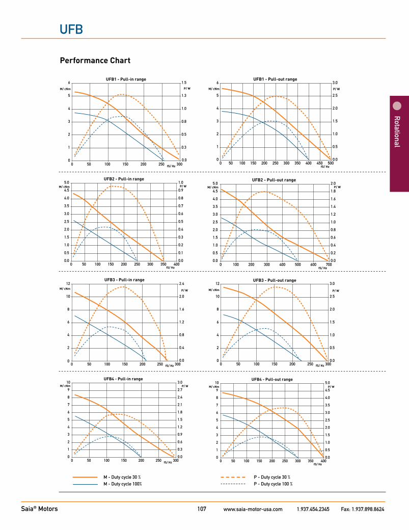
Performance Chart
UFB1 - Pull-in range
0
1
2
3
4
5
6
0 50 100 150 200 250 300fS/ Hz
M/ cNm
0.0
0.3
0.5
0.8
1.0
1.3
1.5P/ W
UFB1 - Pull-out range
00 50 100 150 200 250 300 350 400 450 500
0.0
0.5
1.0
1.5
2.0
2.5
3.0
P/ W
1
2
3
4
5
6
fS/ Hz
M/ cNm
UFB1 - Pull-in range
0
1
2
3
4
5
6
0 50 100 150 200 250 300fS/ Hz
M/ cNm
0.0
0.3
0.5
0.8
1.0
1.3
1.5P/ W
UFB1 - Pull-out range
00 50 100 150 200 250 300 350 400 450 500
0.0
0.5
1.0
1.5
2.0
2.5
3.0
P/ W
1
2
3
4
5
6
fS/ Hz
M/ cNm
UFB2 - Pull-out range
100 200 300 400 500 600 700fS/ Hz
0.0
0.2
0.4
0.6
0.8
1.0
1.2
1.4
1.6
1.8
2.0P/ W
0.0
0.5
1.0
1.5
2.0
2.5
3.0
3.5
4.0
4.5
5.0
0
M/ cNm
0 50 100 150 200 250 300 350 400fS/ Hz
0.0
0.1
0.2
0.3
0.4
0.5
0.6
0.7
0.8
0.9
1.0UFB2 - Pull-in range
0.0
0.5
1.0
1.5
2.0
2.5
3.0
3.5
4.0
4.5
5.0M/ cNm P/ W
UFB3 - Pull-in range
0
2
4
6
8
10
12
0 50 100 150 200 250 300fS/ Hz
M/ cNm
0.0
0.4
0.8
1.2
1.6
2.0
2.4
P/ W
UFB3 - Pull-out range
150 200 250 300fS/ Hz
0.0
0.5
1.0
1.5
2.0
2.5
3.0
P/ W
0
2
4
6
8
10
12
0 50 100
M/ cNm
UFB3 - Pull-in range
0
2
4
6
8
10
12
0 50 100 150 200 250 300fS/ Hz
M/ cNm
0.0
0.4
0.8
1.2
1.6
2.0
2.4
P/ W
UFB3 - Pull-out range
150 200 250 300fS/ Hz
0.0
0.5
1.0
1.5
2.0
2.5
3.0
P/ W
0
2
4
6
8
10
12
0 50 100
M/ cNm
UFB4 - Pull-in range
0
1
2
3
4
5
6
7
8
9
10
0 50 100 150 200 250 300fS/ Hz
M/ cNm
0.0
0.3
0.6
0.9
1.2
1.5
1.8
2.1
2.4
2.7
3.0P/ W
0
1
2
3
4
5
6
7
8
9
10
0 50 100 150 200 250 300 350 400fS/ Hz
M/ cNm
UFB4 - Pull-out range
0.0
0.5
1.0
1.5
2.0
2.5
3.0
3.5
4.0
4.5
5.0P/ W
UFB4 - Pull-in range
0
1
2
3
4
5
6
7
8
9
10
0 50 100 150 200 250 300fS/ Hz
M/ cNm
0.0
0.3
0.6
0.9
1.2
1.5
1.8
2.1
2.4
2.7
3.0P/ W
0
1
2
3
4
5
6
7
8
9
10
0 50 100 150 200 250 300 350 400fS/ Hz
M/ cNm
UFB4 - Pull-out range
0.0
0.5
1.0
1.5
2.0
2.5
3.0
3.5
4.0
4.5
5.0P/ W
M - Duty cycle 30 % P - Duty cycle 30 %M - Duty cycle 100% P - Duty cycle 100 %

Saia® Motors www.saia-motor-usa.com 1.937.454.2345 Fax: 1.937.898.8624108
UHD
Rot
atio
nal
Standard Data
Climatic class wide-spread according to DIN IEC 60721-2-1 Ambient temperature operation -15 ... +55° C Ambient temperature storage -20 ... +100° C Thermal resistance at f=0 (Rtherm) 9 K/W (UHD 1/2/5/6); 6,7 K/W (UHD 3/4/7/8) Thermal class A according to DIN EN 60085 (B on request) Approval standard (UL/CSA on request) Mounting any position Electrical connection cable Protection IP 30 according to DIN EN 60529 Weight (g) 300 (UHD 1/2/5/6), 580 (UHD 3/4/7/8) Rotor stalling motor can be stopped when voltage is applied, without being overheated Bearings sintered bronze, self-lubricating Electric strength according to DIN EN 60034-1/DIN EN 60335-1
Type
Configuration
Rotor shaft, mounting
Approval
Resistance
Direction
Cable
Stepper Motor UHD 1 0 N 36 R N
1 bipolar, two coils, standard magnet 3 bipolar, four coils, standard magnet 2 unipolar, two coils, standard magnet 4 unipolar, four coils, standard magnet 5 bipolar, two coils, stronger magnet 7 bipolar, four coils, stronger magnet 6 unipolar, two coils, stronger magnet 8 unipolar, four coils, stronger magnet
0 centring 12 mm, shaft 6,35 mm, clip ** 3 centring 12 mm, shaft 6,35 mm, screw plate* 1 centring 12 mm, shaft 4,0 mm, clip ** 4 centring 12 mm, shaft 4,0 mm, screw plate* 2 centring 12 mm, shaft 3,0 mm, clip ** 5 centring 12 mm, shaft 3,0 mm, screw plate*
N Standard
see next pages Resistance per winding for bipolar or unipolar.
reversible
N cable 150 mm (other on request)
* not for UHD3/4/7/8** not for UHD1/2/5/6
Order Reference
Dimensions (mm)
Step angle (°)
Holding torque (cNm)
Detent torque(cNm)
Winding
Gear combination
UHD1/2/5/6; UHD3/4/7/8∅ 59 x 35 / ∅ 59 x 70
7.5
13–24 (UHD1/2/5/6); 27,5–45,5 (UHD3/4/7/8)
1.3–2,1 (UHD1/2/5/6); 3,4–5,3 (UHD3/4/7/8)
bipolar/unipolar
J

Saia® Motors www.saia-motor-usa.com 1.937.454.2345 Fax: 1.937.898.8624109
UHD
Rotational
Technical Data UHD1/2/5/6
bipolar (UHD1/5) Rated voltage UN V 6 12 24
Resistance per winding R20 Ω 6,8 36 168
Holding torque cNm 17,1 (UHD1); 24 (UHD5)
Detent torque MS cNm 1,3 (UHD1/2); 2,1 (UHD5/6)
Rotor inertia JR gcm2 49 (UHD1/2); 56 (UHD5/6)
unipolar (UHD2/6) Rated voltage UN V 6 12 24
Resistance per winding R20 Ω 10 45 190
Holding torque cNm 13 (UHD2); 17,3 (UHD6)
Detent torque MS cNm 1,3 (UHD1/2); 2,1 (UHD5/6)
Rotor inertia JR gcm2 49 (UHD1/2); 56 (UHD5/6)
Steps per revolution 48
Duty cycle 100%
Winding temperature Tmax 130° C
Direction of rotation reversible
Dimensions
∅D Shaft
6.35 h6
4.00 h8
3,00 g8

Saia® Motors www.saia-motor-usa.com 1.937.454.2345 Fax: 1.937.898.8624110
UHD
Rot
atio
nal
Performance Chart
UHD1 - Pull-in range
0
2
4
6
8
10
12
14
16
0 50 100 150 200 250 300fS/ Hz
M/ cNm
0.0
0.2
0.4
0.6
0.8
1.0
1.2
1.4
1.6P/ W
UHD1 - Pull-out range
0
2
4
6
8
10
12
14
16
0 50 100 150 200 250 300 350 400fS/ Hz
M/ cNm
0.0
0.2
0.4
0.6
0.8
1.0
1.2
1.4
1.6P/ W
UHD1 - Pull-in range
0
2
4
6
8
10
12
14
16
0 50 100 150 200 250 300fS/ Hz
M/ cNm
0.0
0.2
0.4
0.6
0.8
1.0
1.2
1.4
1.6P/ W
UHD1 - Pull-out range
0
2
4
6
8
10
12
14
16
0 50 100 150 200 250 300 350 400fS/ Hz
M/ cNm
0.0
0.2
0.4
0.6
0.8
1.0
1.2
1.4
1.6P/ W
UHD2 - Pull-in range
0
3
6
9
12
15
0 50 100 150 200 250 300 350 400fS/ Hz
M/ cNm
0.0
0.3
0.6
0.9
1.2
1.5
P/ W
UHD2 - Pull-out range
0
3
6
9
12
15
18
0 50 100 150 200 250 300 350 400fS/ Hz
M/ cNm
0.0
0.3
0.6
0.9
1.2
1.5
1.8
P/ W
UHD2 - Pull-in range
0
3
6
9
12
15
0 50 100 150 200 250 300 350 400fS/ Hz
M/ cNm
0.0
0.3
0.6
0.9
1.2
1.5
P/ W
UHD2 - Pull-out range
0
3
6
9
12
15
18
0 50 100 150 200 250 300 350 400fS/ Hz
M/ cNm
0.0
0.3
0.6
0.9
1.2
1.5
1.8
P/ W
UHD5 - Pull-in range
0
2
4
6
8
10
12
14
16
18
20
0 50 100 150 200 250 300fS/ Hz
M/ cNm
0.0
0.2
0.4
0.6
0.8
1.0
1.2
1.4
1.6
1.8
2.0P/ W
UHD5 - Pull-out range
0
2
4
6
8
10
12
14
16
18
20
0 50 100 150 200 250 300 350 400fS/ Hz
M/ cNm
0.0
0.2
0.4
0.6
0.8
1.0
1.2
1.4
1.6
1.8
2.0P/ W
UHD5 - Pull-in range
0
2
4
6
8
10
12
14
16
18
20
0 50 100 150 200 250 300fS/ Hz
M/ cNm
0.0
0.2
0.4
0.6
0.8
1.0
1.2
1.4
1.6
1.8
2.0P/ W
UHD5 - Pull-out range
0
2
4
6
8
10
12
14
16
18
20
0 50 100 150 200 250 300 350 400fS/ Hz
M/ cNm
0.0
0.2
0.4
0.6
0.8
1.0
1.2
1.4
1.6
1.8
2.0P/ W
UHD6 - Pull-in range
0
3
6
9
12
15
0 50 100 150 200 250 300 350 400fS/ Hz
M/ cNm
-0.2
0.2
0.6
1.0
1.4
1.8
P/ W
UHD6 - Pull-out range
0
3
6
9
12
15
18
0 50 100 150 200 250 300 350 400fS/ Hz
M/ cNm
0.0
0.3
0.6
0.9
1.2
1.5
1.8P/ W
UHD6 - Pull-in range
0
3
6
9
12
15
0 50 100 150 200 250 300 350 400fS/ Hz
M/ cNm
-0.2
0.2
0.6
1.0
1.4
1.8
P/ W
UHD6 - Pull-out range
0
3
6
9
12
15
18
0 50 100 150 200 250 300 350 400fS/ Hz
M/ cNm
0.0
0.3
0.6
0.9
1.2
1.5
1.8P/ W
M - Duty cycle 30 % P - Duty cycle 30 %M - Duty cycle 100% P - Duty cycle 100 %

Saia® Motors www.saia-motor-usa.com 1.937.454.2345 Fax: 1.937.898.8624111
UHD
Rotational
Technical Data UHD3/4/7/8
bipolar (UHD3/7) Rated voltage UN V 12 24 48
Resistance per winding R20 Ω 20 108 460
Holding torque cNm 37,5 (UHD3); 45,5 (UHD7)
Detent torque MS cNm 3,4 (UHD3/4); 5,3 (UHD7/8)
Rotor inertia JR gcm2 135 (UHD3/4); 141 (UHD7/8)
unipolar (UHD4/8) Rated voltage UN V 6 12 24
Resistance per winding R20 Ω 6,75 28,5 120
Holding torque cNm 27,5 (UHD4); 33,5 (UHD8)
Detent torque MS cNm 3,4 (UHD3/4); 5,3 (UHD7/8)
Rotor inertia JR gcm2 135 (UHD3/4); 141 (UHD7/8)
Steps per revolution 48
Duty cycle 100%
Winding temperature Tmax 130° C
Direction of rotation reversible
Dimensions

Saia® Motors www.saia-motor-usa.com 1.937.454.2345 Fax: 1.937.898.8624112
UHD
Rot
atio
nal
Performance Chart
0
5
10
15
20
25
30
35
0 50 100 150 200fS/ Hz
M/ cNm
0.0
0.5
1.0
1.5
2.0
2.5
3.0
3.5P/ W
UHD3 - Pull-in range
UHD3 - Pull-out range
0
5
10
15
20
25
30
35
40
0 50 100 150 200 250fS/ Hz
M/ cNm
0.0
0.5
1.0
1.5
2.0
2.5
3.0
3.5
4.0P/ W
0
5
10
15
20
25
30
35
0 50 100 150 200fS/ Hz
M/ cNm
0.0
0.5
1.0
1.5
2.0
2.5
3.0
3.5P/ W
UHD3 - Pull-in range
UHD3 - Pull-out range
0
5
10
15
20
25
30
35
40
0 50 100 150 200 250fS/ Hz
M/ cNm
0.0
0.5
1.0
1.5
2.0
2.5
3.0
3.5
4.0P/ W
UHD4 - Pull-in range
0
5
10
15
20
25
0 50 100 150 200fS/ Hz
M/ cNm
0.0
0.5
1.0
1.5
2.0
2.5
P/ W
UHD4 - Pull-out range
0
5
10
15
20
25
30
0 50 100 150 200 250fS/ Hz
M/ cNm
0.0
0.5
1.0
1.5
2.0
2.5
3.0P/ W
UHD4 - Pull-in range
0
5
10
15
20
25
0 50 100 150 200fS/ Hz
M/ cNm
0.0
0.5
1.0
1.5
2.0
2.5
P/ W
UHD4 - Pull-out range
0
5
10
15
20
25
30
0 50 100 150 200 250fS/ Hz
M/ cNm
0.0
0.5
1.0
1.5
2.0
2.5
3.0P/ W
UHD7 - Pull-in range
0
5
10
15
20
25
30
35
40
0 50 100 150 200fS/ Hz
M/ cNm
0.0
0.5
1.0
1.5
2.0
2.5
3.0
3.5
4.0P/ W
UHD7 - Pull-out range
0
5
10
15
20
25
30
35
40
45
50
0 50 100 150 200 250fS/ Hz
M/ cNm
0.0
1.0
2.0
3.0
4.0
5.0
P/ W
UHD7 - Pull-in range
0
5
10
15
20
25
30
35
40
0 50 100 150 200fS/ Hz
M/ cNm
0.0
0.5
1.0
1.5
2.0
2.5
3.0
3.5
4.0P/ W
UHD7 - Pull-out range
0
5
10
15
20
25
30
35
40
45
50
0 50 100 150 200 250fS/ Hz
M/ cNm
0.0
1.0
2.0
3.0
4.0
5.0
P/ W
0
5
10
15
20
25
30
0 50 100 150 200fS/ Hz
M/ cNm
0.0
0.5
1.0
1.5
2.0
2.5
3.0P/ W
UHD8 - Pull-in range
20
25
30
35
40
0 50 100 150 200 250fS/ Hz
M/ cNm
2.0
2.5
3.0
3.5
4.0P/ W
UHD8 - Pull-out range
0
5
10
15
0.0
0.5
1.0
1.5
0
5
10
15
20
25
30
0 50 100 150 200fS/ Hz
M/ cNm
0.0
0.5
1.0
1.5
2.0
2.5
3.0P/ W
UHD8 - Pull-in range
20
25
30
35
40
0 50 100 150 200 250fS/ Hz
M/ cNm
2.0
2.5
3.0
3.5
4.0P/ W
UHD8 - Pull-out range
0
5
10
15
0.0
0.5
1.0
1.5
M - Duty cycle 30 % P - Duty cycle 30 %M - Duty cycle 100% P - Duty cycle 100 %

Saia® Motors www.saia-motor-usa.com 1.937.454.2345 Fax: 1.937.898.8624113
UP
Rotational
Dimensions (mm)
Step angle (°)
Holding torque (cNm)
Detent torque(cNm)
Winding
Gear combination
UP (ST6443; ST6444)∅ 64 x 43
7,5/11,25 (ST6443); 11,25 (ST6444)
30–35 (ST6443); 45 (ST6444)
2–2,5 (ST6443); 7 (ST6444)
bipolar
O, P, R
Standard Data
Climatic class wide-spread according to DIN IEC 60721-2-1Ambient temperature operation °C -15 ... +40 Ambient temperature storage °C -20 ... +100Thermal resistance at f=0 Rtherm 29 K/W Thermal class B (ST6443); A (ST6444) according to DIN EN 60085Approval standardMounting any positionElectrical connection cableProtection IP 30 according to DIN EN 60529Weight 500 g (ST6443); 550 g (ST6444)Rotor stalling motor can be stopped when voltage is applied, without being overheatedBearings Sintered bronze, self- lubricating
Stepper Motor ST6443 / ST6444 7,5° 3,7 Ω
7,5° (ST6443)11,25° (ST6443 / ST6444)
3,7 Ω
Type
Step angle
Resistance
Order Reference

Saia® Motors www.saia-motor-usa.com 1.937.454.2345 Fax: 1.937.898.8624114
UP
Rot
atio
nal
Technical Data
bipolar (ST6443) Rated voltage UN V 4,5 4,5 Resistance per winding R20 Ω 3,7 Step angle ° 7,5 11,25 Holding torque MH cNm 35 30 Detent torque Ms cNm 2,5 2 Rotor inertia JR gcm2 85
Steps per revolution 48 32 Winding temperature increase K 90 Current per winding A 1,25 Inductance per winding mH 10 9,5 Power consumption W 11,5 Driver mode Chopper drive
bipolar (ST6444) Rated voltage UN V 4,5 Resistance per winding R20 Ω 3,7 Step angle ° 11,25 Holding torque MH cNm 45 Detent torque Ms cNm 7 Rotor inertia JR gcm2 180
Steps per revolution 32 Winding temperature increase K 90 Current per winding A 1,25 Inductance per winding mH 8 Power consumption W 11,5 Driver mode Chopper drive
Circuit diagram Motor connections - bipolar
A
B
A
A1yellow
A2blue
B1red
B2grey
A1A2
B1B2
B
clockwise rotation

Saia® Motors www.saia-motor-usa.com 1.937.454.2345 Fax: 1.937.898.8624115
UP
Rotational
Performance Chart (chopper driver)
ST6443 UPD1 (ST6443/7,5/1) UPJ1 (ST 6443/11,25/1)
M/cNm M/cNm
fs/Hz fs/Hz
ST6444
Dimensions
Standard - wire length: 150 mmGeneral tolerances acc. to DIN ISO 2768-mk
M/cNm
fs/Hz
UPJ5 (ST 6444/11,25)
*
* on request 14h9