stepper motor control
DESCRIPTION
final project in EE 177.1 (Logic Circuits and Switching Theory Laboratory)TRANSCRIPT

STEPPER MOTOR CONTROL(Project)

MINDANAO STATE UNIVERSITY-ILIGAN INSTITUTE OF TECHNOLOGY
DEPARTMENT OF EECE
STEPPER MOTOR CONTROL
Submitted to: Submitted by:
Jeffrey C. Pasco Verano, Jeric S.
Juanday, Juhaira M.Sinugbuhan, Sheramay C.
Cebedo, Erika

INTRODUCTION:
A stepper motor is an electromechanical device which converts electrical pulses into discrete mechanical movements. The shaft or spindle of a stepper motor rotates in discrete step increments when electrical command pulses are applied to it in the proper sequence. The motors rotation has several direct relationships to these applied input pulses. The sequence of the applied pulses is directly related to the direction of motor shafts rotation. The speed of the motor shafts rotation is directly related to the frequency of the
input pulses and the length of rotation is directly related to the number of input pulses applied.
There are a wide variety of stepper types. There are two basic winding arrangements for the electromagnetic coils in a two phase stepper motor: bipolar and unipolar.
UNIPOLARA unipolar stepper motor has one
winding with center tap per phase. Each section of windings is switched on for each direction of magnetic field. Since in this arrangement a magnetic pole can be reversed without switching the direction of current, the commutation circuit can be made very simple (e.g., a single transistor) for each winding. Typically, given a phase, the center tap of each winding is made common: giving three leads per phase and six leads for a typical two phase motor.BIPOLAR
Bipolar motors have a single winding per phase. The current in a winding needs to be reversed in order to reverse a magnetic pole, so the driving circuit must be more complicated, typically with an H-bridge arrangement (however there are several off-the-shelf driver chips available to make this a simple affair). There are two leads per phase, none are common.
Static friction effects using an H-bridge have been observed with certain
drive topologies.[2]
a center-tapped unipolar winding, which allows the field to be reversed by turning one winding off and the other on
as a bipolar winding, which requires reversal of the current flow to reverse the field.

Dithering the stepper signal at a higher frequency than the motor can respond to will reduce this "static friction" effect.
Because windings are better utilized, they are more powerful than a unipolar motor of the same weight. This is due to the physical space occupied by the windings. A unipolar motor has twice the amount of wire in the same space, but only half used at any point in time, hence is 50% efficient (or approximately 70% of the torque output available). Though a bipolar stepper motor is more complicated to drive, the abundance of driver chips means this is much less difficult to achieve.
Specifically, a bipolar stepper motor (EM323) was used in this project in making a counter.
METHODOLOGY:
counter
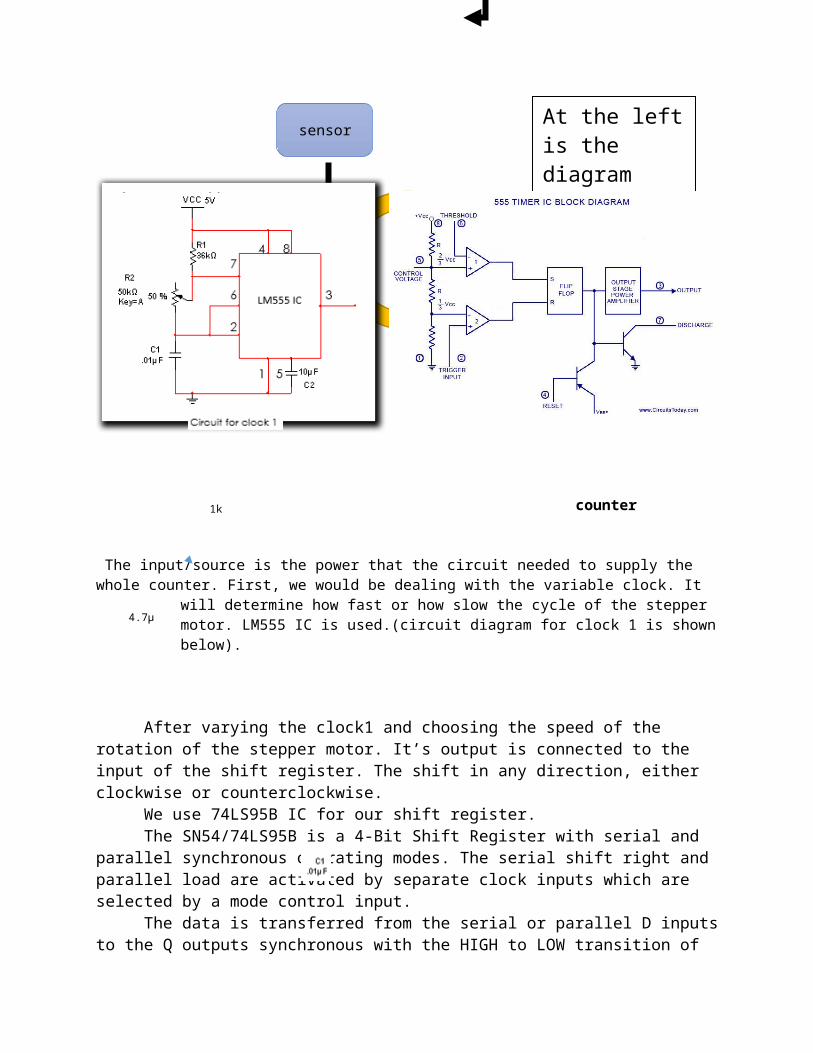
The input/source is the power that the circuit needed to supply the whole counter. First, we would be dealing with the variable clock. It will
Input/Source
At the left is the diagram showing of the whole process of making a counter.
Shift register
Clock 1
Clock 2
H-bridge drivers
Stepper motor
sensor

determine how fast or how slow the cycle of the stepper motor. LM555 IC is used.(circuit diagram for clock 1 is shown below).
After varying the clock1 and choosing the speed of the rotation of the stepper motor. It’s output is connected to the input of the shift register. The shift in any direction, either clockwise or counterclockwise.
We use 74LS95B IC for our shift register.The SN54/74LS95B is a 4-Bit Shift Register with serial and parallel
synchronous operating modes. The serial shift right and parallel load are activated by separate clock inputs which are selected by a mode control input.
The data is transferred from the serial or parallel D inputs to the Q outputs synchronous with the HIGH to LOW transition of the appropriate clock input.
Below are the circuit diagram and other information regarding 74LS95.
Circuit diagram of shift register pinout configuration of 74LS9B
1k
4.7µF
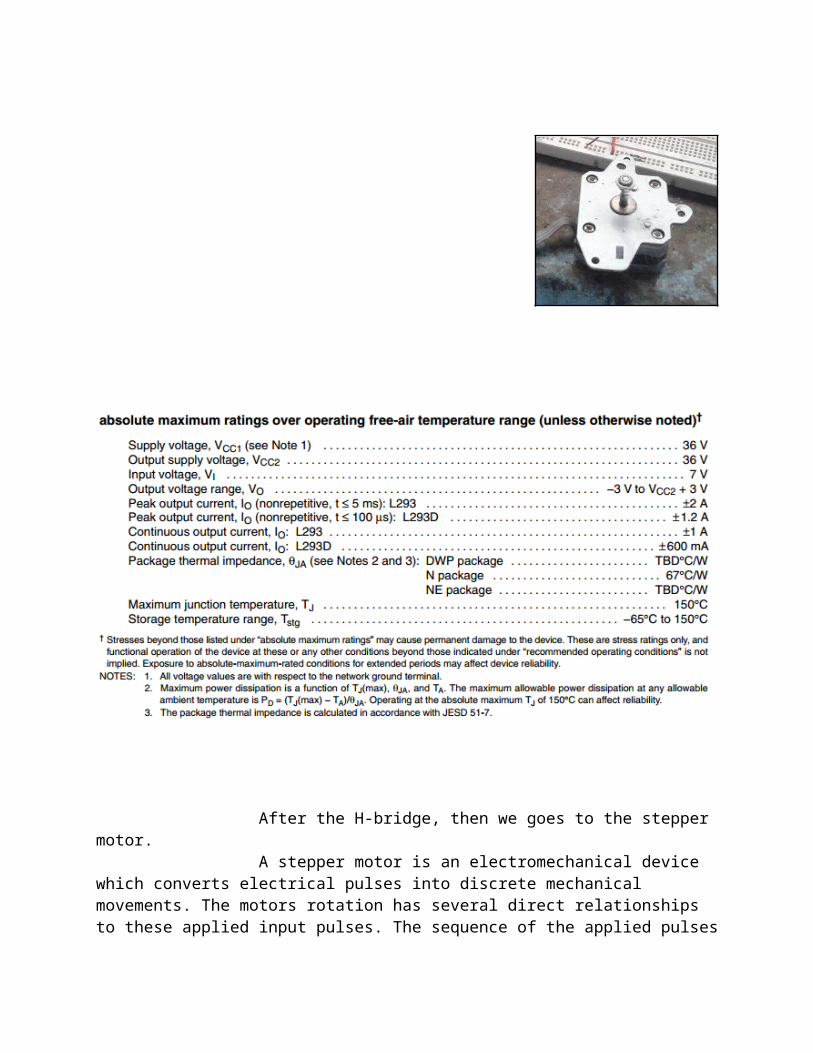
Then the output of the shift register then goes to the H-bridge. An H bridge is an electronic circuit that enables a voltage to be applied across a load in either direction. These circuits are often used in robotics and other applications to allow DC motors to run forwards and backwards. Here SN754410/ L293NE IC is what we have used. The L293 and L293D are quadruple high-current half-H drivers. The L293 is designed to provide bidirectional drive currents of up to 1 A at voltages from 4.5 V to 36 V. These devices are designed to drive inductive loads such as relays, solenoids, dc and bipolar stepping motors, as well as other high-current/high-voltage loads in positive-supply applications. All inputs are TTL compatible. Each output is a complete totem-pole drive circuit, with a Darlington transistor sink and a pseudo Darlington source. Drivers are enabled in pairs, with drivers 1 and 2 enabled by 1,2EN and drivers 3 and 4 enabled by 3,4EN. When an enable input is high, the associated drivers are enabled, and their outputs are active and in phase with their inputs. When the enable input is low, those drivers are disabled, and their outputs are off and in the high-impedance state. With the proper data inputs, each pair of drivers forms a full-H (or bridge) reversible drive suitable for solenoid or

motor applications. On the L293, external high-speed output clamp diodes should be used for inductive transient suppression.A VCC1 terminal, separate from VCC2, is provided for the logic inputs to minimize device power dissipation.The L293and L293D are characterized for operation from 0°C to 70°C.
Below are the pinout and information about L293NE IC.

Block diagram of L293 Logic diagram of L293

After the H-bridge, then we goes to the stepper motor. A stepper motor is an electromechanical device which converts electrical pulses into discrete mechanical movements. The motors rotation has several direct relationships to these applied input pulses. The sequence of the applied pulses is directly related to the direction of motor shafts rotation. The speed of the motor shafts rotation is directly related to the frequency of the input pulses and the length of rotation is directly related to

the number of input pulses applied. The number of turns that the spindle would make per minute would be shown on the counter.
In this project, we use a bipolar stepper motor (EM323).
A bipolar stepper motor has one winding per stator phase. A two phase bipolar stepper motor will have 4 leads. In a bipolar stepper we don’t have a common lead like in a uni-polar stepper motor. Hence, there is no natural reversal of current direction through the winding.
A bipolar stepper motor has easy wiring arrangement but its operation is little complex. In order to drive a bipolar stepper, we need a driver IC with an internal H bridge circuit. This is because, in order to reverse the polarity of stator poles, the current needs to be reversed. This can only be done through a H bridge.
There are two other reasons to use an H Bridge IC:
1) The current draw of a stepper motor is quite high. The micro-controller pin can only provide up to 15 mA at maximum. The stepper needs current which is around ten times this value. An external driver IC is capable of handling such high currents.2) Another reason why H Bridge is used is because the stator coils are nothing but inductor. When coil current changes direction a spike is generated. A normal micro-controller pin cannot tolerate such high spikes without damaging itself. Hence to protect micro-controller pins, H-bridge is necessary. Then, the sensor is used to indicate every time the spindle of the motor would make a rotation. In our case, we use a tickle switch. Every time the tickle switch would be touched by the spindle of the stepper motor, the counter would count.
The output of the sensor will be the input of our decoder. Now, our decoder which serves as our counter will record the number of pulses that our sensor have delivered. This displays the revolution per minute (rpm) made by the motor which is indicated by the sensor. Using a BCD or 7-segment (cathode) and a CD4026 IC, the binary inputs are decoded to produce the desired output.
Sensor circuit
V15 V
Q1
BC549BP
R1660kΩ
R22kΩ
S1
Key = Space
U1
The output is also dependent to clock 2. Clock 2 is a constant clock. Frequency is 1/60Hz. It will only create a pulse in the 60th second. When the clock 2 reaches the 60th second, it would stop counting. The BCD would then display the last count. The clock is then reset back to 0.
Clock 2 is almost the same as clock 1. It’s just that, it does not consist of a potentiometer, instead, it has a fixed resistor that has a value of 8.6kΩ. We also use a 1kΩ instead of 36kΩ.
Below are the pinout and other information regarding the IC that we used for the counter.
CD4026 is a Johnson counter IC commonly used in digital display. It has a 5 stage Johnson decade counter with a decoder which converts the Johnson code to a 7 segment decoded output. To put it simply, it will convert the input into numeric display and can be seen on 7 segment display or with LED. It can be used for displaying analogue value such as temperature with pic microcontroller or for counting objects. There is various other applications like in 7 segment decimal display circuit, in clocks, timer etc. Advantages of 4026 counter are: It contains counters and 7 segment
Pin configuration of CD4026
8.6MΩ
68kΩ

decoded in one package, It can be easily interfaced with 7 segment types, Ideal for low power display. Operated at wide range of temperature from 5V to 20V and the biggest advantage of the 4026B counter IC is that it can drive a 7-segment display without needing a decoder driver IC.

THE BLOCK DIAGRAM OF THE OVERALL CIRCUIT OF THE STEPPER MOTOR CONTROL

t(s)
t(s)
RESULTS AND DISCUSSIONS:TIMING DIAGRAMS:
Our stepper motor is bipolar which implies that it has four pins that will create rotation if and only if in every state there’s only one pin that is in logic “HI” and it follows a sequence. For clockwise, we have A-D-C-B and for counter clockwise we have B-C-D-A. As we can observe, our sequencing works like that of a shift register. Now, that is the reason why we make use of a shift register operation in our circuit. However, since we are using TTL, we can only produce a current that is enough to drive our stepper motor. Now, in order to regulate a current that can drive our stepper motor, we used an H-bridge circuit, which works like that of an amplifier. (In our case, we used the H-bridge of an L293NE IC). This time, we’ve obtain enough current to make our bipolar motor turn/rotate.
Bipolar Stepper Motor
Since our clock 1 is variable, there’s no stable timing diagram for every part of the
project. We set the clock 1 to have a frequency of
1 Hz so that it would produce one pulse per second. Consequently, it produces 60
rotations per minute.
0 60
0 60
60
59 60 61
Clock 2
Sensor

The final output of our stepper motor control.
REFERENCES
http://www.circuitstoday.com/wp-content/uploads/2009/09/555-timer-IC-Block-Diagram.jpg
http://www.cs.smith.edu/~thiebaut/270/datasheets/sn74ls95brev5.pdf
http://electrical4u.com/bipolar-stepper-motor/
http://www.circuitsgallery.com/2013/12/4026-digital-counter-circuit.html
http://www.engineersgarage.com/electronic-circuits/Interfacing-4026-with-7-segment-display