step8 first step with ac500 on ethernet - abb ltd · cp500 soft: first step with ac500 series on...
TRANSCRIPT
Type des. Prep FRENT BERTRAND 01/2007
Doc. Kind Function Description No. Of P
Appr. / Resp. dept.
Title CP500 Soft: First Step with AC500 series on
Ethernet, Step8 11
Doc no. Lang. Rev. Ind.
ABB ABB Entrelec 1SBC159100M0202_Ch8 En 1
CP500 CONTROL PANELS
CP500 Soft: First Step with AC500 series on
Ethernet
Step8
CP500 Soft: First Step with AC500 series on Ethernet, Step8
Doc. no Lang. Rev. Ind. Page
ABB ABB Entrelec 1SBC159100M0202_Ch8 En 2
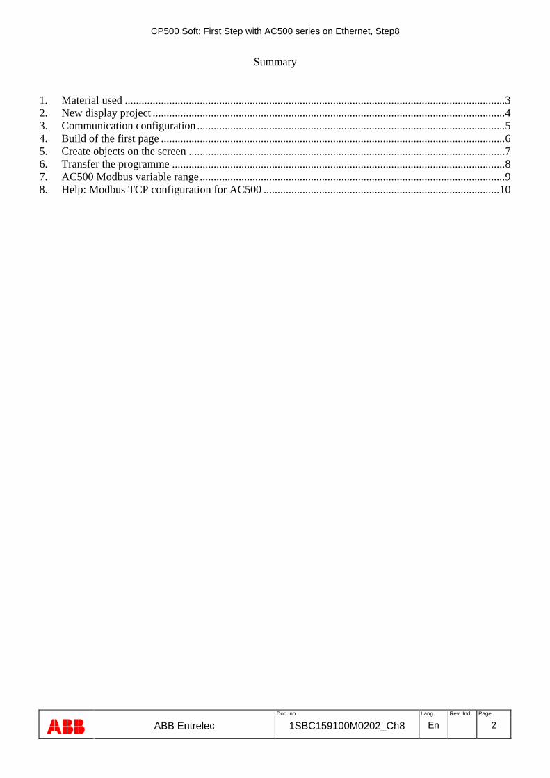
Summary
1. Material used .........................................................................................................................................3 2. New display project ...............................................................................................................................4 3. Communication configuration ...............................................................................................................5 4. Build of the first page ............................................................................................................................6 5. Create objects on the screen ..................................................................................................................7 6. Transfer the programme ........................................................................................................................8 7. AC500 Modbus variable range..............................................................................................................9 8. Help: Modbus TCP configuration for AC500 .....................................................................................10
CP500 Soft: First Step with AC500 series on Ethernet, Step8
Doc. no Lang. Rev. Ind. Page
ABB ABB Entrelec 1SBC159100M0202_Ch8 En 3
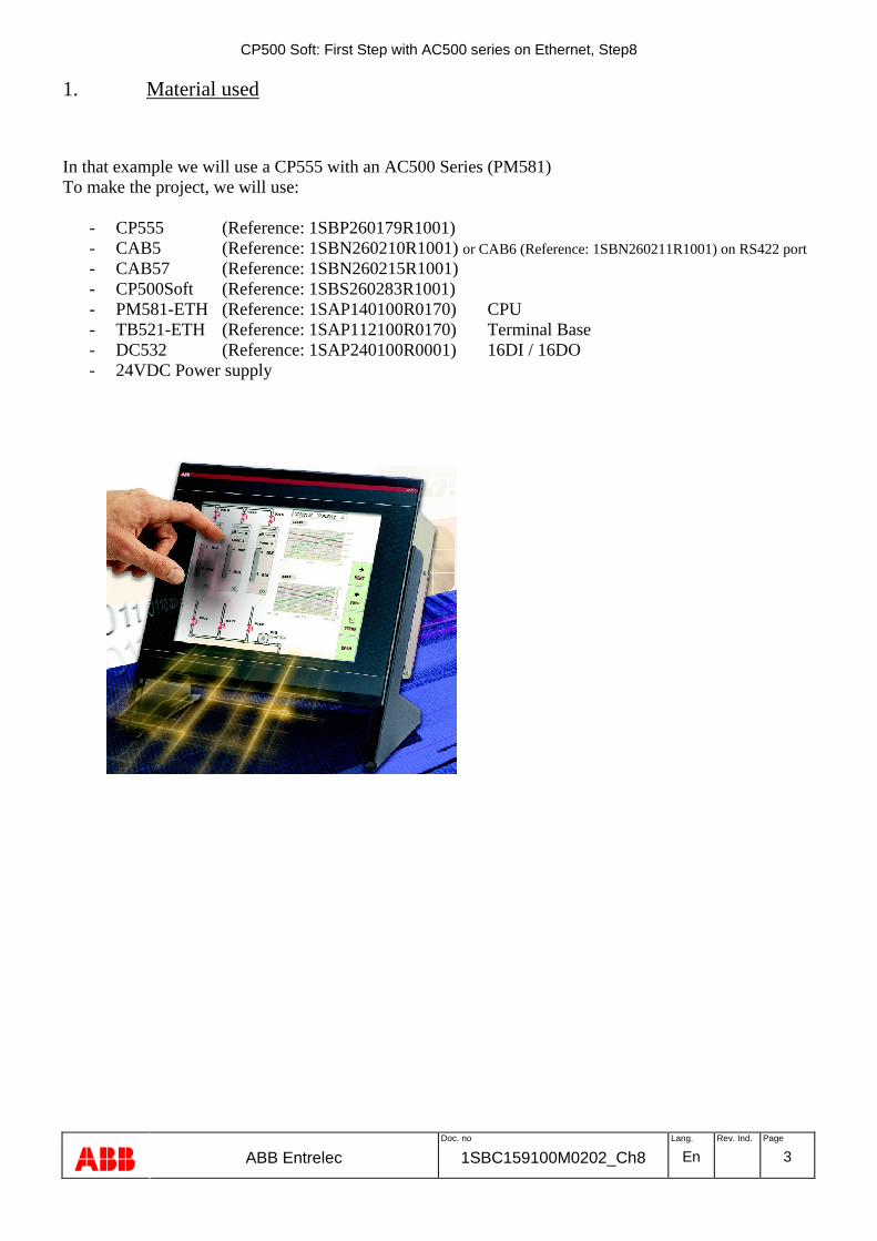
1. Material used
In that example we will use a CP555 with an AC500 Series (PM581) To make the project, we will use:
- CP555 (Reference: 1SBP260179R1001) - CAB5 (Reference: 1SBN260210R1001) or CAB6 (Reference: 1SBN260211R1001) on RS422 port - CAB57 (Reference: 1SBN260215R1001) - CP500Soft (Reference: 1SBS260283R1001) - PM581-ETH (Reference: 1SAP140100R0170) CPU - TB521-ETH (Reference: 1SAP112100R0170) Terminal Base - DC532 (Reference: 1SAP240100R0001) 16DI / 16DO - 24VDC Power supply

CP500 Soft: First Step with AC500 series on Ethernet, Step8
Doc. no Lang. Rev. Ind. Page
ABB ABB Entrelec 1SBC159100M0202_Ch8 En 4
2. New display project
1- In Start / Programs / CP500Soft / CP Programmer / Programmer: Open the CP500 Programmer.
2 – Choose File / New
3 – The menu beside appears to choose the CP product and the protocol from the PLC you will use (Driver). Click on Change
4 - Choose the display in the list and valid with OK. Our example: CP555
5 – Same operation for the PLC in choosing the Driver “ABB / Modbus TCP AC500 / AC500 PM581/591 Series” and valid with OK.
CP500 Soft: First Step with AC500 series on Ethernet, Step8
Doc. no Lang. Rev. Ind. Page
ABB ABB Entrelec 1SBC159100M0202_Ch8 En 5
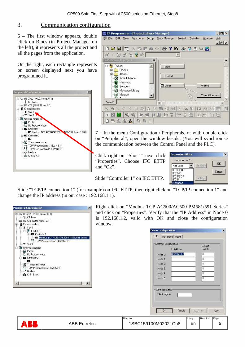
3. Communication configuration
6 – The first window appears, double click on Blocs (in Project Manager on the left), it represents all the project and all the pages from the application. On the right, each rectangle represents on screen displayed next you have programmed it.
7 – In the menu Configuration / Peripherals, or with double click on “Peripheral”, open the window beside. (You will synchronise the communication between the Control Panel and the PLC). Click right on “Slot 1” next click “Properties”. Choose IFC ETTP and “Ok”.
Slide “Controller 1” on IFC ETTP. Slide “TCP/IP connection 1” (for example) on IFC ETTP, then right click on “TCP/IP connection 1” and change the IP address (in our case : 192.168.1.1).
Right click on “Modbus TCP AC500/AC500 PM581/591 Series” and click on “Properties”. Verify that the “IP Address” in Node 0 is 192.168.1.2, valid with OK and close the configuration window.

CP500 Soft: First Step with AC500 series on Ethernet, Step8
Doc. no Lang. Rev. Ind. Page
ABB ABB Entrelec 1SBC159100M0202_Ch8 En 6
4. Build of the first page
6 – is the first page, which will appear when you power the product. Arrows represent the links between the different screens. Double click on
the window bellow open.
8 – On the bottom find the toolbar, it contains all the objects possible to use for the model of control panel you use. When you put the mouse on the different objects (Wait some seconds), there functionality appears.
Main
Main
CP500 Soft: First Step with AC500 series on Ethernet, Step8
Doc. no Lang. Rev. Ind. Page
ABB ABB Entrelec 1SBC159100M0202_Ch8 En 7
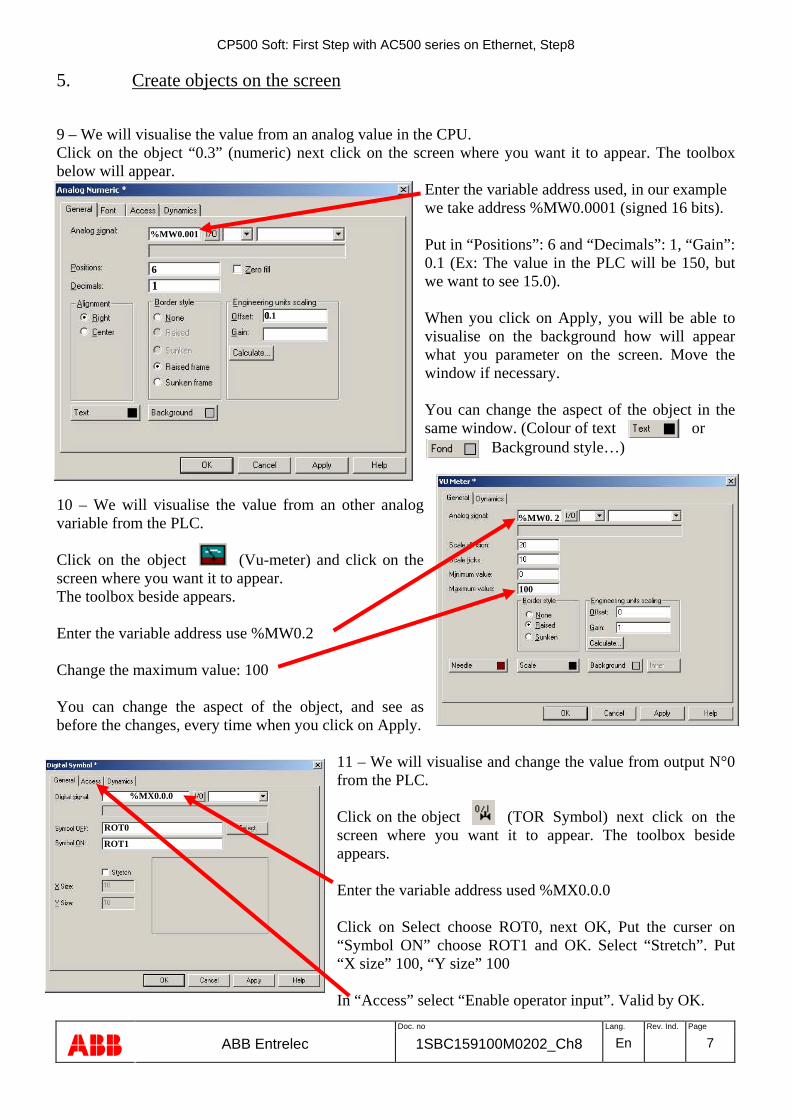
5. Create objects on the screen
9 – We will visualise the value from an analog value in the CPU. Click on the object “0.3” (numeric) next click on the screen where you want it to appear. The toolbox below will appear.
Enter the variable address used, in our example we take address %MW0.0001 (signed 16 bits). Put in “Positions”: 6 and “Decimals”: 1, “Gain”: 0.1 (Ex: The value in the PLC will be 150, but we want to see 15.0). When you click on Apply, you will be able to visualise on the background how will appear what you parameter on the screen. Move the window if necessary. You can change the aspect of the object in the same window. (Colour of text or
Background style…)
10 – We will visualise the value from an other analog variable from the PLC. Click on the object (Vu-meter) and click on the screen where you want it to appear. The toolbox beside appears. Enter the variable address use %MW0.2 Change the maximum value: 100 You can change the aspect of the object, and see as before the changes, every time when you click on Apply.
11 – We will visualise and change the value from output N°0 from the PLC. Click on the object (TOR Symbol) next click on the screen where you want it to appear. The toolbox beside appears. Enter the variable address used %MX0.0.0 Click on Select choose ROT0, next OK, Put the curser on “Symbol ON” choose ROT1 and OK. Select “Stretch”. Put “X size” 100, “Y size” 100 In “Access” select “Enable operator input”. Valid by OK.
%MW0.001
6
1
0.1
%MW0. 2
100
%MX0.0.0
ROT0
ROT1

CP500 Soft: First Step with AC500 series on Ethernet, Step8
Doc. no Lang. Rev. Ind. Page
ABB ABB Entrelec 1SBC159100M0202_Ch8 En 8
6. Transfer the programme
You have created what you want to see on the screen and make the connection between the Control Panel and the PLC. To verify the project, click on the Glasses
12 – Click on to transfer the project in the CP555. The window beside appears, click on Send. Confirm by “Yes”. It’s possible just to send a part of the project: unselect “Send complete project”. Disconnect the CAB5 and connect instead CAB57 with the PM581 (Possible to use CAB6 on RS422 connector and the changes are made without to be obliged to disconnect all the time the PLC). In AC500 you have to configure the communication and to affect the variable to the output in the PS501 Soft: %MX0.0.0 = %QX0.0.0 When you are Online on PS501 you can modify the analog value and see the result on CP555. You can now see on the CP555, the values change when you change the variable in the CPU. Click on the selector, it activate or inactivate the output “0” from the CPU.

CP500 Soft: First Step with AC500 series on Ethernet, Step8
Doc. no Lang. Rev. Ind. Page
ABB ABB Entrelec 1SBC159100M0202_Ch8 En 9
7. AC500 Modbus variable range
Ranges access for the different CPUs PM571: 4 kB 1 segment of variables available: %MX0.0.0 to MX0.4095.7 %MB0.0 to %MB0.4095 %MW0.0 to %MW0.2047 %MD0.0 to %MD0.1023 PM581,PM582 and PM591: 128 kB 2 segments of variables available: %MX0.0.0 to MX0. 65535.7 %MB0.0 to %MB0. 65535 %MW0.0 to %MW0.32767 %MD0.0 to %MD0.16383 %MX1.0.0 to MX1. 65535.7 %MB1.0 to %MB1. 65535 %MW1.0 to %MW1.32767 %MD1.0 to %MD1.16383 WARNING If you use data table the data could not begin in segment “1” and finish in segment 2. It will create an error message. Structure extraction
CP500 Soft: First Step with AC500 series on Ethernet, Step8
Doc. no Lang. Rev. Ind. Page
ABB ABB Entrelec 1SBC159100M0202_Ch8 En 10
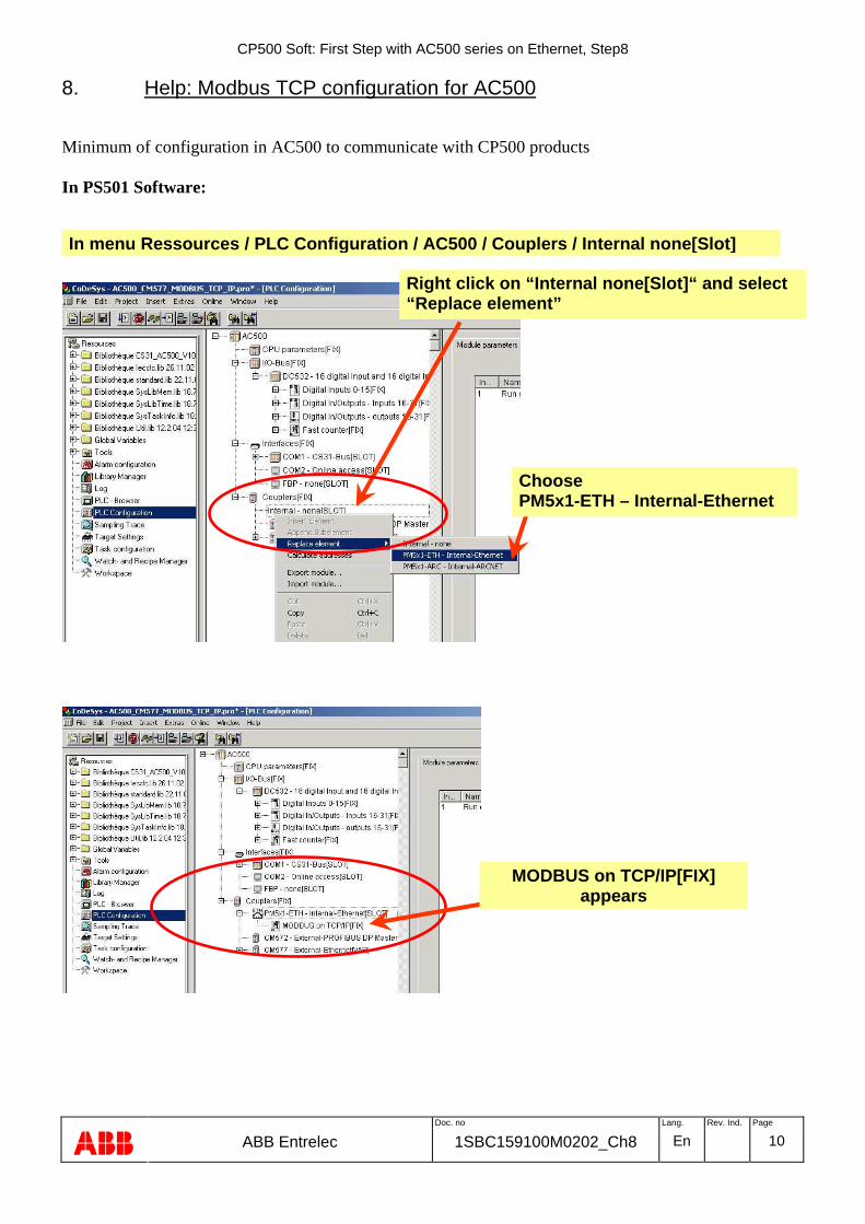
8. Help: Modbus TCP configuration for AC500
Minimum of configuration in AC500 to communicate with CP500 products In PS501 Software:
Right click on “Internal none[Slot]“ and select “Replace element”
MODBUS on TCP/IP[FIX] appears
In menu Ressources / PLC Configuration / AC500 / Couplers / Internal none[Slot]
Choose PM5x1-ETH – Internal-Ethernet
CP500 Soft: First Step with AC500 series on Ethernet, Step8
Doc. no Lang. Rev. Ind. Page
ABB ABB Entrelec 1SBC159100M0202_Ch8 En 11
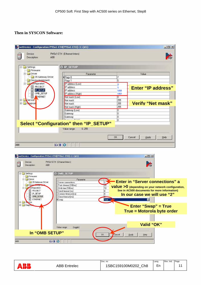
Then in SYSCON Software:
Select “Configuration” then “IP_SETUP”
Enter “IP address”
Verify “Net mask”
192 168 1 2
In “OMB SETUP”
Enter in “Server connections” a value >0 (depending on your network configuration,
See in AC500 documents for more information)
In our case we will use “2”
Enter “Swap” = True True = Motorola byte order
Valid “OK”