step by step guide to build a cisco wireless infrastructure using cisco wlc 5500
TRANSCRIPT
Step by Step guide to build a Cisco wireless infrastructure using Cisco WLC 5500, Cisco 1142 AP and Microsoft Radius serverApril 30, 2010
Pre-requisites:
1. Microsoft Active Directory and DNS
2. DHCP Server with new scope configured
3. IP helper-address configured
4. Microsoft Radius (IAS) Server 2003 or Microsoft Network Policy Server 2008
5. Microsoft Enterprise root CA
6. Cisco Wireless LAN controller (WLC) 5500
7. Cisco AIR-LAP1142N wireless access point (AP)
8. Separate VLAN for wireless infrastructure
9. WLC, AP and IAS placed in same VLAN
10. Windows 7 or Windows XP or Mac OSX/snow leopard client
Assumptions:
1) AD and DNS working perfect.
2) DHCP Server IP: 10.10.9.4
New scope for Wireless Network
IP range: 10.10.10.1-10.10.11.254 Subnet Mask:255.255.255.0
Gateway:10.10.10.1 Exclusion:10.10.10.1-10.10.10.10
NTP :10.10.9.5
3) WLC
IP:10.10.10.2 WLC subnet:255.255.255.0 Gateway:10.10.10.1
Time provider:10.10.9.5
4) IAS IP:10.10.10.3 subnet:255.255.255.0 Gateway:10.10.10.1
5) IP ranges 10.10.10.1-10.10.11.254 added in the internal networks in ISA or forefront
TMG.
6)Interface 1 of WLC connected to a trunk port of Layer3 switch or core switch
7)wireless infrastructure VLAN ID/Tag 100
Add Lightweight Cisco Aironet 1142 in DHCP Server
Note: Follow these steps for newly added DHCP scope mentioned in assumptions.
1.In order to configure these options in the Windows DHCP server, open the DHCP
Server Administration Tool or MMC. Right-click the DHCP root, and then choose Define
Vendor Classes.
2.The DHCP Vendor Classes utility appears. Click Add.
3.A New Class configuration box appears. Enter a value for the Display Name field, for
example, “Cisco Aironet c1142 AP”, and an appropriate description such as “Vendor
Class identifier for Cisco Aironet c1142 AP”. Click the ASCII Section and enter the
appropriate string value such as “Cisco AP c1142” (without inverted coma) for the
Vendor Class Identifier. Click OK. Then, click Close on the DHCP Vendor Classes
window.
4.Add an entry for the WLAN controller sub-type as a pre-defined option configured for
the Vendor Class. Right-click the DHCP Server Root, and then choose Set Predefined
Options.
5.Choose the newly created Vendor Option Class in the Option Class field, and then
click Add.
6.The Option Type box appears. In the Name field, enter a string value, for example,
Option 43. Choose IP Address as the Data Type. Check the Array check box. In the
Code field, enter the sub-option code value 241 (0xf1). Enter a Description such as
Wireless LAN Controller IP address. Click OK.
7.The Vendor Class and sub-option are now programmed into the DHCP server. Now,
the vendor specific information must be defined for the AP DHCP scope. Choose the
appropriate DHCP scope. Right-click Scope Options, and choose Configure Options.
8.Click the Advanced tab. Choose the Vendor Class you previously defined. Check
the 241 Option 43 check box, and then enter each WLC management interface IP
address(s) Example: 10.10.10.2. Click Apply.
9.Once you complete this step, the DHCP Option 43 is configured. This DHCP option is
IP address, the DHCP server sends the option 43 as well as to the LAPs. Now the DHCP
option 43 (241 Cisco Wireless AP) that is made available for a newly created DHCP
scope for Cisco.
10. To verify, click on the scope options in the newly created DHCP scope, you will see
241 Cisco Wireless AP or what you mentioned in Description.
Add a new VLAN in core switch(example: Cisco 4506) or L3 switch:
Note: Entire wireless infrastructure will be placed in this VLAN.
Switch#vlan database
Switch(vlan)#vlan 100
Switch(vlan)#name Wireless Network
Switch(vlan)#exit
switch#configure terminal
Switch(config-if)#interface vlan 100
Switch(config-if)#Description Wireless Network
Switch(config-if)#ip helper-address 10.10.9.4
Switch(config-if)#IP address 10.10.10.1 255.255.255.0
Switch(config-if)#no shutdown
Switch(config-if)#end
switch#wr
Create a Trunk Port in Core switch (Cisco 4506) or L3 Switch
Note: This trunk will be connecting with Cisco WLC 5500 using CAT6 or Fibre optic.
Switch# configure terminal
Switch(config)#interface gigabitethernet 6/11
(6/11 means Module 6 and Port 11)
Switch(config)#switchport trunk encapsulation dot1q
Switch(config)#SwitchPort Mode trunk
Switch(config)#end
Switch# wr
Switch#show run
Create VLAN in a switch (Example: Cisco 2960G)
Note: This port will be connecting with Cisco 1142 AP. Wherever you want an wireless
AP, configure a port with same vlan. For this article VLAN 100. connect AP with this port
after configuring the following. repeat for all the APs.
Switch# configure terminal
Switch(config)#
Switch(config)#interface Gigabitethernet 0/7
Switch(config)#switchport access vlan 100
Switch(config)#end
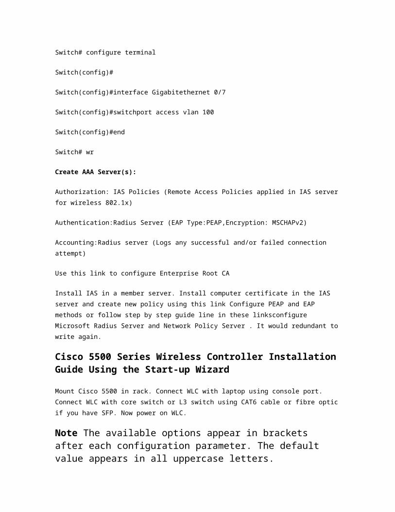
Switch# wr
Create AAA Server(s):
Authorization: IAS Policies (Remote Access Policies applied in IAS server for wireless
802.1x)
Authentication:Radius Server (EAP Type:PEAP,Encryption: MSCHAPv2)
Accounting:Radius server (Logs any successful and/or failed connection attempt)
Use this link to configure Enterprise Root CA
Install IAS in a member server. Install computer certificate in the IAS server and create
new policy using this link Configure PEAP and EAP methods or follow step by step guide
line in these linksconfigure Microsoft Radius Server and Network Policy Server . It would
redundant to write again.
Cisco 5500 Series Wireless Controller Installation Guide Using the Start-up Wizard
Mount Cisco 5500 in rack. Connect WLC with laptop using console port. Connect WLC
with core switch or L3 switch using CAT6 cable or fibre optic if you have SFP. Now
power on WLC.
Note The available options appear in brackets after each configuration parameter. The default value appears in all uppercase letters.
Note Press the hyphen key if you need to return to the previous command line. To configure the controller for basic operation using the Start-up Wizard, follow these steps:
Step 1 When prompted to terminate the Auto-Install process, enteryes. If you do not enter yes, the Auto-Install process begins after 30 seconds.
Note The Auto-Install feature downloads a configuration file from a TFTP server and then loads the configuration onto the controller automatically.
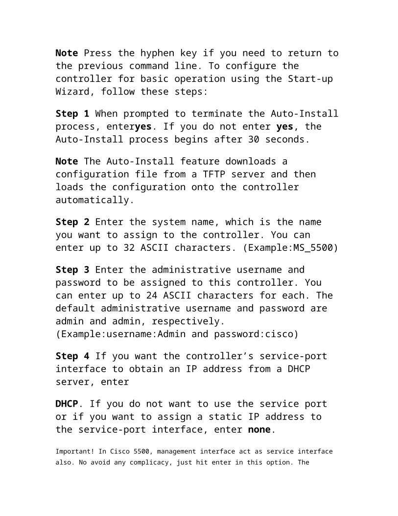
Step 2 Enter the system name, which is the name you want to assign to the controller. You can enter up to 32 ASCII characters. (Example:MS_5500)
Step 3 Enter the administrative username and password to be assigned to this controller. You can enter up to 24 ASCII characters for each. The default administrative username and password are admin and admin, respectively.(Example:username:Admin and password:cisco)
Step 4 If you want the controller’s service-port interface to obtain an IP address from a DHCP server, enter
DHCP. If you do not want to use the service port or if you want to assign a static IP address to the service-port interface, enter none.
Important! In Cisco 5500, management interface act as service interface also. No avoid
any complicacy, just hit enter in this option. The service-port interface controls
communications through the service port. Its IP address must be on a different subnet
from the management interface. This configuration enables you to manage the
controller directly or through a dedicated management network to ensure service
access during network downtime.
Step 5 If you entered none in Step 4, enter the IP address and netmask for the service-port interface on the next two lines.
Step 6 Enable or disable link aggregation (LAG) by choosing yes or no. You may type No if you don’t have two or more Cisco WLC.
Step 7 Enter the IP address, netmask, default router IP address, and optional VLAN identifier (a valid VLAN identifier or 0 for an untagged VLAN) for the management interface.
Note The VLAN identifier should be set to match the switch interface configuration. Example: IP:10.10.10.2 WLC
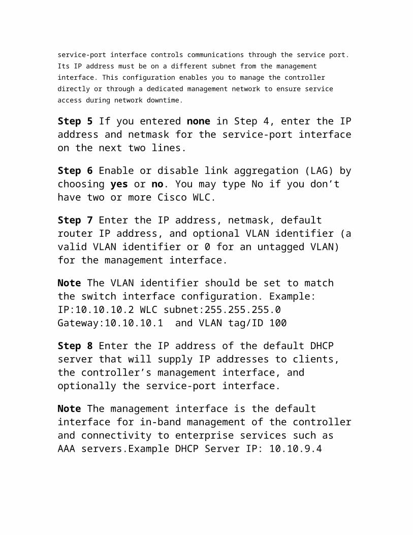
subnet:255.255.255.0 Gateway:10.10.10.1 and VLAN tag/ID 100
Step 8 Enter the IP address of the default DHCP server that will supply IP addresses to clients, the controller’s management interface, and optionally the service-port interface.
Note The management interface is the default interface for in-band management of the controller and connectivity to enterprise services such as AAA servers.Example DHCP Server IP: 10.10.9.4
Step 9 Enter the IP address of the controller’s virtual interface, which will be used by all controller Layer 3 security and mobility managers. You should enter a fictitious, unassigned IP address, such as 1.1.1.1.
Note The virtual interface is used to support mobility management, DHCP relay, and embedded Layer 3 security such as guest web authentication and VPN termination. All controllers within a mobility group must be configured with the same virtual interface IP address.
Step 10 If desired, enter the name of the mobility group/RF group to which you want the controller to belong.
Note Although the name that you enter here is assigned to both the mobility group and the RF group, these groups are not identical. Both groups define clusters of controllers, but they have different purposes. All of the controllers in an RF group are usually also in the same mobility group and vice versa. However, a mobility group facilitates scalable, system-wide mobility and controller redundancy while an RF group facilitates scalable, system-wide dynamic RF management.
Step 11 Enter the network name, or service set identifier (SSID). The initial SSID enables basic functionality of the
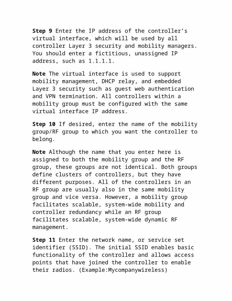
controller and allows access points that have joined the controller to enable their radios. (Example:Mycompanywireless)
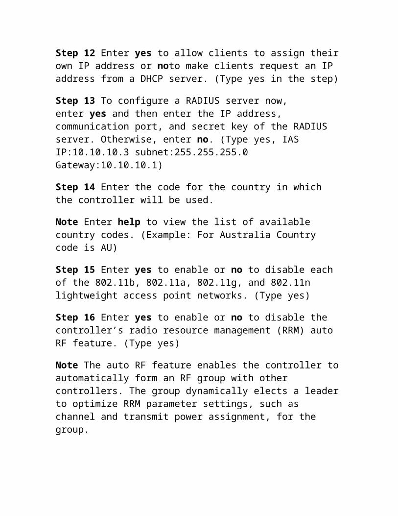
Step 12 Enter yes to allow clients to assign their own IP address or noto make clients request an IP address from a DHCP server. (Type yes in the step)
Step 13 To configure a RADIUS server now, enter yes and then enter the IP address, communication port, and secret key of the RADIUS server. Otherwise, enter no. (Type yes, IAS IP:10.10.10.3 subnet:255.255.255.0 Gateway:10.10.10.1)
Step 14 Enter the code for the country in which the controller will be used.
Note Enter help to view the list of available country codes. (Example: For Australia Country code is AU)
Step 15 Enter yes to enable or no to disable each of the 802.11b, 802.11a, 802.11g, and 802.11n lightweight access point networks. (Type yes)
Step 16 Enter yes to enable or no to disable the controller’s radio resource management (RRM) auto RF feature. (Type yes)
Note The auto RF feature enables the controller to automatically form an RF group with other controllers. The group dynamically elects a leader to optimize RRM parameter settings, such as channel and transmit power assignment, for the group.
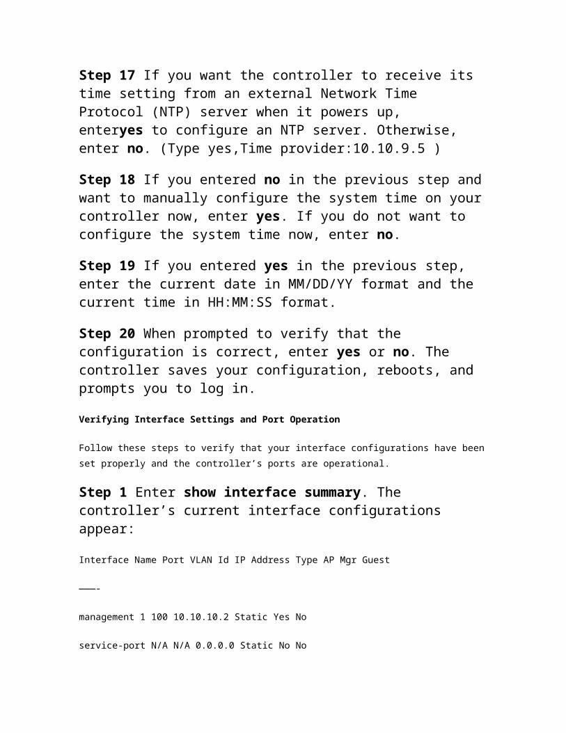
Step 17 If you want the controller to receive its time setting from an external Network Time Protocol (NTP) server when it powers up, enteryes to configure an NTP server. Otherwise, enter no. (Type yes,Time provider:10.10.9.5 )
Step 18 If you entered no in the previous step and want to manually configure the system time on your controller now, enter yes. If you do not want to configure the system time now, enter no.
Step 19 If you entered yes in the previous step, enter the current date in MM/DD/YY format and the current time in HH:MM:SS format.
Step 20 When prompted to verify that the configuration is correct, enter yes or no. The controller saves your configuration, reboots, and prompts you to log in.
Verifying Interface Settings and Port Operation
Follow these steps to verify that your interface configurations have been set properly
and the controller’s ports are operational.
Step 1 Enter show interface summary. The controller’s current interface configurations appear:
Interface Name Port VLAN Id IP Address Type AP Mgr Guest
———-
management 1 100 10.10.10.2 Static Yes No
service-port N/A N/A 0.0.0.0 Static No No
virtual N/A N/A 1.1.1.1 Static No No
Step 2 Enter show port summary. The following information appears, showing the status of the controller’s distribution system ports, which serve as the data path between the controller and Cisco lightweight access points and to which the controller’s management interface is mapped.
STP Admin Physical Physical Link Link Mcast
Pr Type Stat Mode Mode Status Status Trap Appliance POE
– —
1 Normal Forw Enable Auto 1000 Full Up Enable Enable N/A
2 Normal Forw Enable Auto 1000 Full Up Enable Enable N/A
Configure Security and AAA Server in WLC 5500
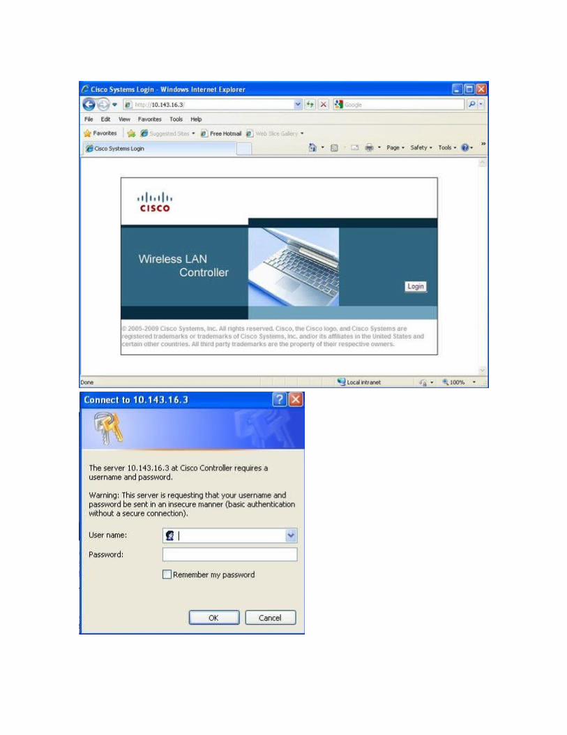
1. Open IE or Firefox Type IP address of WLC in the address bar
ashttps://10.10.10.2 (bypass proxy if you need to)and hit enter.
2. Click Login and provide login credentials you created in start-up wizard.
3. Click on Wireless. In the left hand pan click Authentication. You will see the IP
address and port number 1812 of Radius Server.
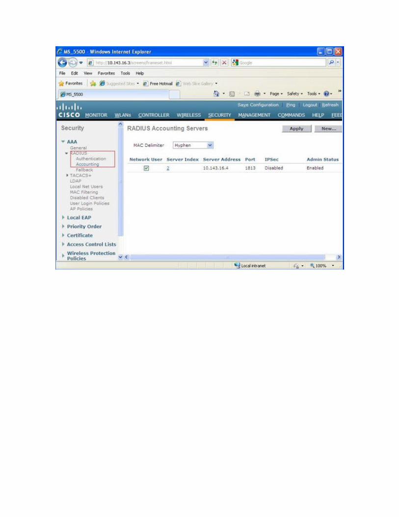
4. In the left hand pan Click on Accounting. Click new on right hand top corner. You will
be presented with a window to add Radius server. provide IP of Radius server, Shared
secret and Port 1813. Apply changes.
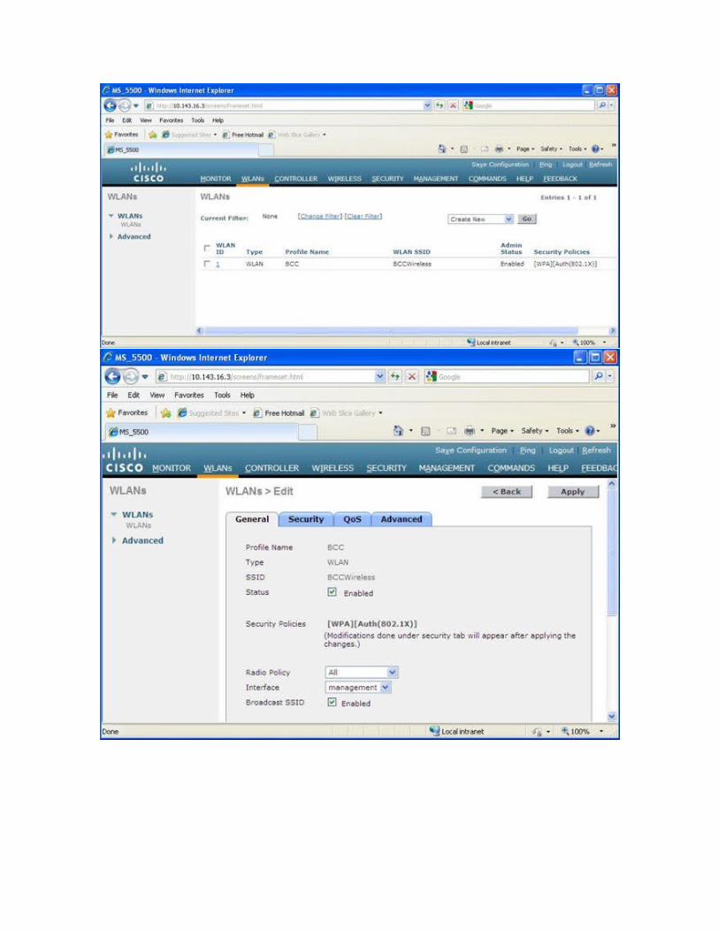
5. Click on WLANs>Click on 1>Click on General Tab>Check Enable on Status and
Check Enabled on broadcast SSID
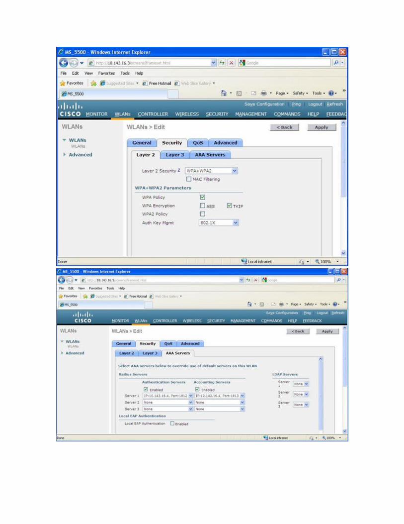
6.Click on Security Tab>Click Layer2 Tab>Select WPA+WPA2 from Layer2 security
drop-down list>Check WPA policy and TKIP or WPA2 policy and TKIP. In the same page,
in Auth Key Mgmt, select 802.1x. Now click on Apply button.
7.Click on AAA Servers>Select Authentication and Accounting server from the server1
drop down list. here Authentication and Accounting server are Radius Server. Check
Enabled in both Authentication and Accounting radio button. Click Apply.
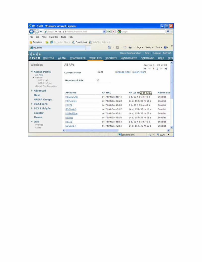
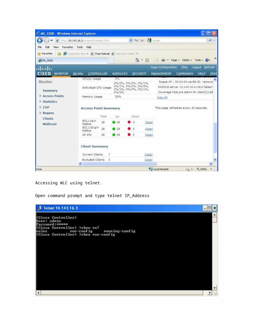
8.In the left hand side top corner, click on to Monitor and scroll down to make sure you
see the all APs.
Add WLC 5500 in the IAS server as a Radius Client
1. Log on to IAS server as an administrator.
2.Open Internet Authentication Service from Administrative Tools

3.Right click on Radius Clients>Click add Radius client. You will be presented with new
radius client window. Type IP address of WLC 5500 and a Friendly Name such as WLC.
Click Next.
4. In the this window, Select Radius Standard as Client-Vendor, Provide shared secret
(must be same as WLC configuration in step 13) and repeat shared secret and click
finish.
5.Close IAS console and log out.
Testing network
Log on to Windows XP or Windows 7 client as a domain users while client is connected
via CAT5 or CAT6 . Make sure this domain user is a member of wireless access group
and allowed to have remote access(dialin TAB of AD user property). Install computer
and user certificate in that client. Now turn on wireless NIC. unplug CAT5 cable. View
available wireless network. Select the SSID, you created in previous steps and double
click. You will be connected.
Important! if you setup WPA and TKIP in WLC then you must setup WPA and TKIP in
Client also. Similar for WPA2 and TKIP or WPA2 and AES. Both sides must match each
other.
For Mac client, see my previous post in the link
Configure Group Policy for 802.1x wireless network
1. Open the Group Policy Management Console (GPMC).
2. Create and link a new group policy object with desired OU
3. Right click on newly created GPO and edit
4. Go to Computer Configuration, open Windows Settings, open Security Settings, and
then select Wireless Network (IEEE 802.11) Policies.
5. right-click Wireless Network (IEEE 802.11) Policies, and then click Create A New Policy
and Type Policy name
6. Open New Network Policy Properties >Click on preferred network Tab>To add a new
profile, click Add>type the SSID that corresponds to the SSID configured on your WLC
security tab.
7. In the Wireless key network, select WPA and TKIP or whatever configured in WLC
8. In the IEEE 802.1x tab,Set EAPOL start message to transmit per IEEE 802.1x
9. In the EAP type select PEAP
10. Check authenticate as computer when computer information is available and
also computer authentication with user authentication from drop down box.
11. Now press Ok, Apply and ok.
Work Around with WLC 5500
Open IE, Type IP of WLC in the address bar (bypassing proxy), hit enter. Click on Logon.
provide logon credentials, click ok.
Accessing WLC using telnet.
Open command prompt and type telnet IP_Address
Necessary Links
Export a certificate with the private key
Import a certificate
Cisco 5500 WLC
Cisco Wireless AP
Microsoft Radius Server
Relevant Articles
WLAN Controller Failover for Lightweight Access Points Configuration Example
Wireless LAN Controller (WLC) Configuration Best Practices
How to configure Microsoft Radius Server (IAS) for Macintosh OSX 10.5, Windows 7 and
windows XP Pro client
Install and configure Microsoft Active Directory Certificate Services (AD CS) using
Windows Server 2008 R2
Windows Server 2008: how to configure Network Policy Server or Radius Server –Step
by Step Guide
Overview of the Wi-Fi Protected Access (WPA) security update in Windows XP