stefan meier, abb grid automation systems, switzerland...
TRANSCRIPT

—DIGITAL SUBSTATION. STANDARD IEC 61850, MOSCOW, JULY 2019
Digital Substation ExperiencesStefan Meier, ABB Grid Automation Systems, Switzerland, Andrey Maslov, ABB Power & Automation Systems, Russia
—
Architecture examples
IEC 61850 logical node modelling
Precise time synchronization
Digitalization beyond substation boundaries
June 26, 2019 Slide 2
Contents

—Architecture examples
—Process bus architecture
June 26, 2019 Slide 4
Advantages and disadvantages
Advantages
– Flexible process data exchange between feeders
– Flexible process data exchange between main 1 and main 2 protection
– Ethernet switches provide connectivity for analyzing and simulation tools (VLANs, MAC address filtering… to be considered)
Disadvantages
– Higher costs due to Ethernet switches
– Dataflow management with VLANs or MAC Address filtering required
Station wide PRP process bus for main 1 and main 2
Gateway
IED
MU
BIED
Main 1
Station bus
Process bus LANA
Main 2
Bay 1
IED
MU
BIED
Switch
Switch
IED
MU
BIED
Main 1 Main 2
Bay 2
IED
MU
BIED
Switch
Switch
BBP
MU
BIED
Main 1 Main 2
Busbar voltage and busbar protection
BBP
MU
BIED
Switch
Switch
Process bus LANB
GPS 1 GPS 2
SNTP SNTPPTP

—Oborniki Slaskie digital substation installation - Poland
June 26, 2019 Slide 5
Digital devices
– 5 x FOCS fiber optic current sensor, redundant
– 10 x SAM600 MU systems (for conv VTs)
– 12 x REF620 as binary process interface
– 4 x REF615 feeder terminals as P&C and MU for transformer diff. protection
– 13 x 670 series protection and control IEDs (RED, RET, REB, REC)
– Station level with redundant GPS (PTP), gateways and HMIs
110kV FOCS and SAM600 installation
Outdoor panel Protection panel

—Oborniki Slaskie digital substation installation - Poland
June 26, 2019 Slide 6
System architecture
PRP station bus
Station-wide PRP process bus, common for main 1 and main 2
2 bay control IEDs for entire substation
Redundant GPS clocks (PTP) with connection to station and process bus
MV feeder terminals as MUs for transformer diff protection (low voltage side)
PRP process bus
ProtectionIEDs
PB PRP switches
SB PRP switches
MV IEDs as MUs
Outdoor panels with FOCS, SAM600, REF620, fully redundant

—Process bus architecture
June 26, 2019 Slide 7
Advantages and disadvantages
Advantages
– Separate bay HSR rings for first and second main protection provide perfect separation
– No disturbances between feeders or main 1/2 protection during service and maintenance
– No dataflow management required in bay rings
– Substation size has no impact on bay HSR ring performance
– No Ethernet switches on process bus
Disadvantages
– Connection between 1st and 2nd main protection only through station bus
– Process data exchange between feeders is limited
– PTP on process bus is critical and may require redundant station bus communication
HSR rings per bay and main protection, separate station-wide rings for BBP
HMIStation bus
HSR process bus
IED
MU
BIED
Main 1 Main 2
IED
MU
BIED
IED
MU
BIED
Main 1 Main 2
IED
MU
BIED
BBP
MU
BIED
Main 1 Main 2
BBP
MU
BIED
HSR process bus
Bay 1 Bay 2 Busbar voltage and busbar protection
- Busbar voltage distribution through station wide rings through bay MUs or through station bus.- MUs in bays forward BB voltage from station HSR ring to bay HSR rings- PTP boundary clock function in IEDs for synchronization of process busses
GPS 1 GPS 2
SNTPPTP
SNTPPTP

—Langedalen digital substation - Norway
June 26, 2019 Slide 8
FOCS, SAM600 and 670 series IEDs
Complete substation with fiber optic current sensors, merging units, breaker IEDs and IEC 61850 process bus.
– redundant FOCS fiber optic current sensors
– SAM600 merging units and breaker IEDs
– 670 series protection and control IEDs with process bus
– HSR process bus ring
110kV AIS substation with FOCS and SAM600
Customer: BKK
Year of commissioning: Dec 2018
Voltage level:132kV

—Langedalen digital substation - Norway
26 de junio de 2019 Slide 9
HSR process bus

—IEC 61850 logical node modelling
—IEC 61850 Modelling
June 26, 2019 Slide 11
Consistent application for protection, control and maintenance
Protection and control IEDs
PDIS, PTOC…
RSYN, RBRF, ATCC…
CSWI, CILO, CSYN, CPOW…
Instrument transf.
TCTR, TVTR
Power transformers
YPTR, YLTC…
SPTR, SLTC, STMP, SIML…
Process level IEDs
PTRC
Breakers, Disconnectors…
XCBR, XSWI
SCBR, SSWI, SIMG, SOPM LPHD, LCCH, LTRK…
LPHD, LCCH, LTRK…
—
IEC TR 61850-7-500, Figure 24June 26, 2019 Slide 12
LN modelling
Bay protection (left: without process bus, right: with process bus)
Protection
Logical Node modelling

—IEC 61850 modelling
26 de junio de 2019 Slide 13
GOOSE SCU to IEDs
Graphical dataflow representation from an SCD file of a digital substation
The boxes, diagonally, represent IEDs and SCUs
Horizontal and vertical lines are GOOSE connections
The highlighted arrows indicate the GOOSE communication from an SCU to the protection and control IEDs of one feeder.
Example

—IEC 61850 modelling
26 de junio de 2019 Slide 14
Transmitted dataset
Right-click on the connections unveils the transmitted datasets
Example
—IEC 61850 modelling
26 de junio de 2019 Slide 15
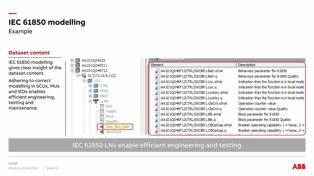
Dataset content
IEC 61850 modelling gives clear insight of the dataset content.
Adhering to correct modelling in SCUs, MUs and IEDs enables efficient engineering, testing and maintenance.
Example
IEC 61850 LNs enable efficient engineering and testing
—IEC 61850 modelling
26 de junio de 2019 Slide 16
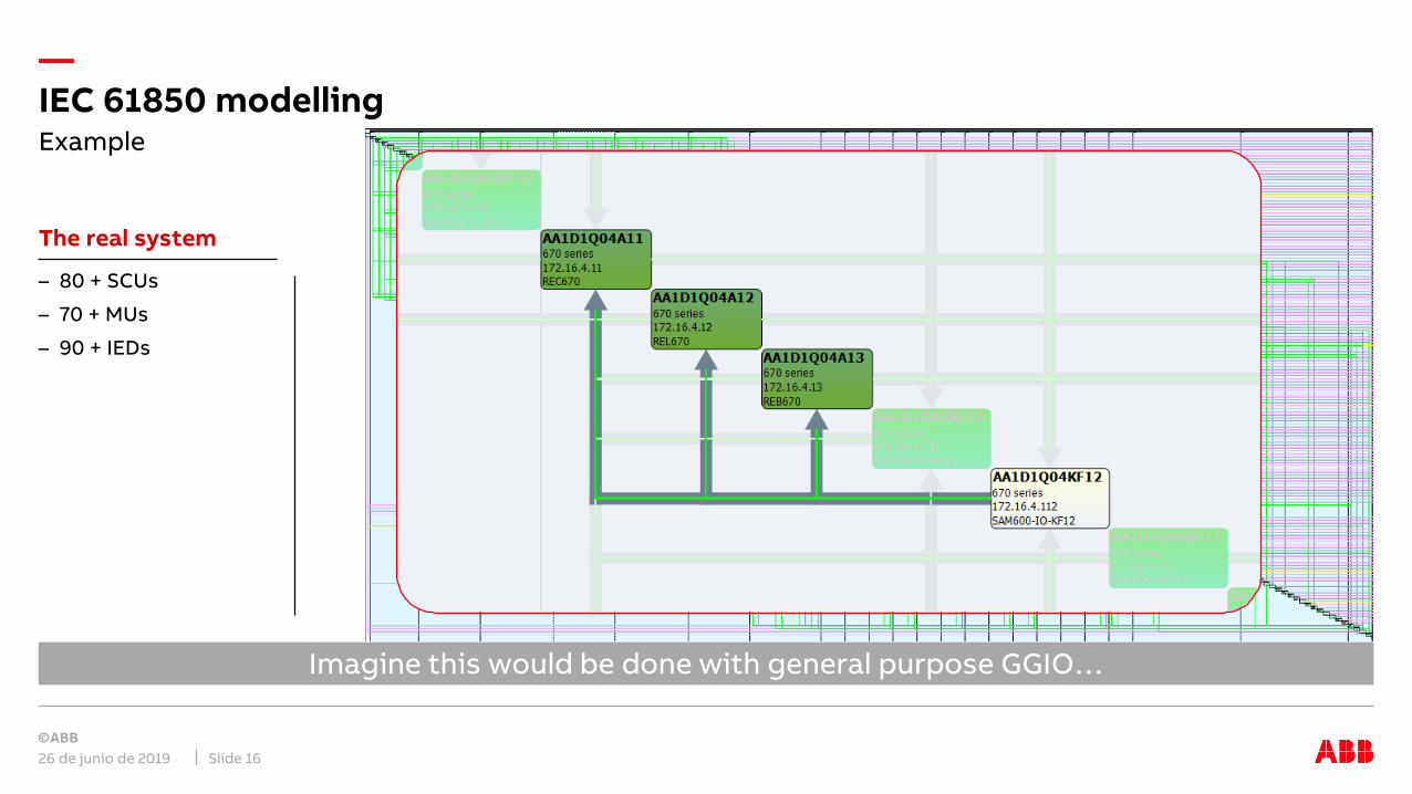
The real system
– 80 + SCUs
– 70 + MUs
– 90 + IEDs
Example
Imagine this would be done with general purpose GGIO…

—IEC 61850 modelling
June 26, 2019 Slide 17
Hardwired signal exchange IEC 61850 GOOSE signal exchange
Enable efficient testing
Testing wire by wire, signal by signal with volt-meter
IEC 61850station bus
Bay level IEDs
Hardwired connections
IEC 61850 process bus
SAM600
GOOSE
Testing of several signals at the same time
Time measurement between status changes
Recording for offline analysis

—
26 de junio de 2019Slide 18

—Precise time synchronization

—Time synchronization
Sample count based on time synchronization
The time synchronization is used to synchronize the sampling of analogue values
It enables synchronous sampling by different physical devices
Reference to absolute time is not always required
Synchronization on process level can be separate from station level
The need to synchronize depends on the application
IEC 61850 specifies for synchronization:
– Phasor measurement applications: 1μs
– Protection applications: 4μs
Synchronization of sampling
June 26, 2019Slide 20
Time
1s0s
Analog value current/ voltage
Sample No
0 0
…
Sampled value current/ voltage
…

—The foundation of digital substations
June 26, 2019 Slide 21
Increased accuracy
Processing of real-time data from different sources requires that the acquisition is synchronized.
Accuracy need changed from 1 Millisecond to 1-4 Microseconds
Precise time synchronization

—Comparison SNTP / PTP / IRIG-B
June 26, 2019 *BMCA: Best Master Clock Algorithm, automatically selects best available master to synchronize the systemSlide 22
Feature SNTP PTP IRIG-B
Architecture
Supported topologies Any Any Only star or daisy chain
Communication infrastructure IEC 61850 Network is used IEC 61850 Network is used Separate Network required
Supported by IEC 61850 compliant devices Yes Yes Limited
Supported by Ethernet switches and routers Yes Yes, if PTP capable No
Support of multiple time masters Yes (limited number of masters) Yes (“unlimited number”, BMCA*) No
Redundant Connection to IEDs Yes (PRP, HSR) Yes (PRP, HSR) No
Interoperability
According IEC 61850 Standard Yes Yes No
Accuracy
Time synchronization accuracy 1 ms 1 µs 100 µs
Time stamp resolution at the IED 1 ms 1 ms 1 ms
Availability and Supervision
Supervision All connections supervised All connections supervised only indirectly via IEDs
Availability High, by using multiple time master Highest (BMCA*) low, only single time master
Economics
Fiber optical cables and cabling costs Low, no separate network required Medium, PTP capable switches High, separate network required
unreliableInsufficient for synch of
sampling
—Time synchronization architecture
June 26, 2019 Slide 23
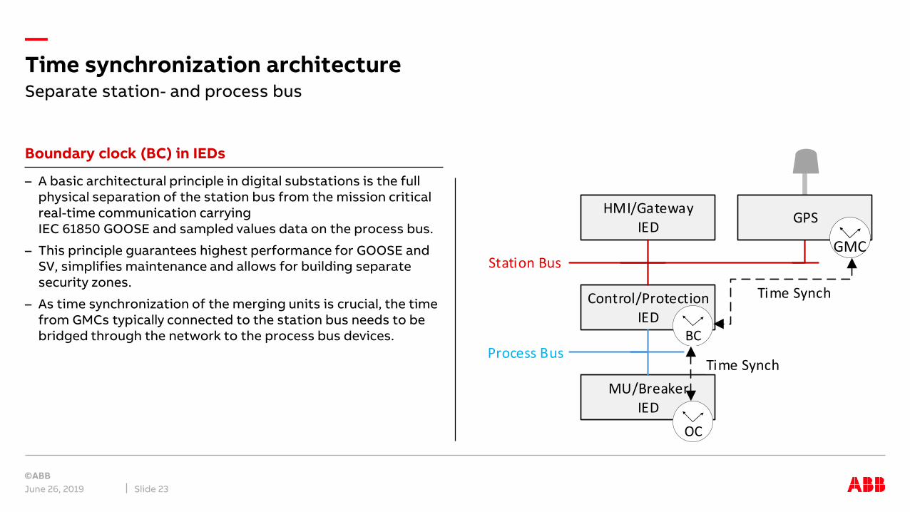
Boundary clock (BC) in IEDs
– A basic architectural principle in digital substations is the full physical separation of the station bus from the mission critical real-time communication carrying IEC 61850 GOOSE and sampled values data on the process bus.
– This principle guarantees highest performance for GOOSE and SV, simplifies maintenance and allows for building separate security zones.
– As time synchronization of the merging units is crucial, the time from GMCs typically connected to the station bus needs to be bridged through the network to the process bus devices.
Separate station- and process bus
MU/BreakerIED
Control/Protection IED
HMI/GatewayIED
Station Bus
Process Bus
Time Synch
GPS
GMC
BC
Time Synch
OC

—Time synchronization architecture
June 26, 2019 Slide 24
Redundant clocks and networks
To avoid this single point of failure it is recommended to have redundant GPS clocks connected to same network.
In the case that the network is designed as PRP, the two GPS clocks are connected as double attached nodes.
Redundant clocks
MU/BreakerIED
Control IED
HMI/GatewayIED
Station Bus
Process Bus
GPS
OC
GMC
GPS
GMCLAN A
LAN B
Time Synch
Protection IED
BCBC

—
As many functions depend on the precise time synchronization, there are a few useful principles that should be followed, to achieve high system availability:
– Redundant GPS clocks or other type of GMCs
– Redundant communication networks (HSR or PRP) for transmission of process data and PTP synchronization
– Redundant protection systems, with dedicated process and bay device for first and second main protection
– Protection and control IEDs that are capable to become time master with best master clock algorithm
– Protection and control IEDs acting as boundary clocks between station and process bus
– Graceful degradation of application functions in case of time synch failures, resulting in blocking of protection functions that depend on consistent synchronization only
Time synchronization architecturePrinciples for robust system design
June 26, 2019Slide 25

—Digitalization beyond substation boundaries
—Real-time communication between substations
June 26, 2019 Slide 27
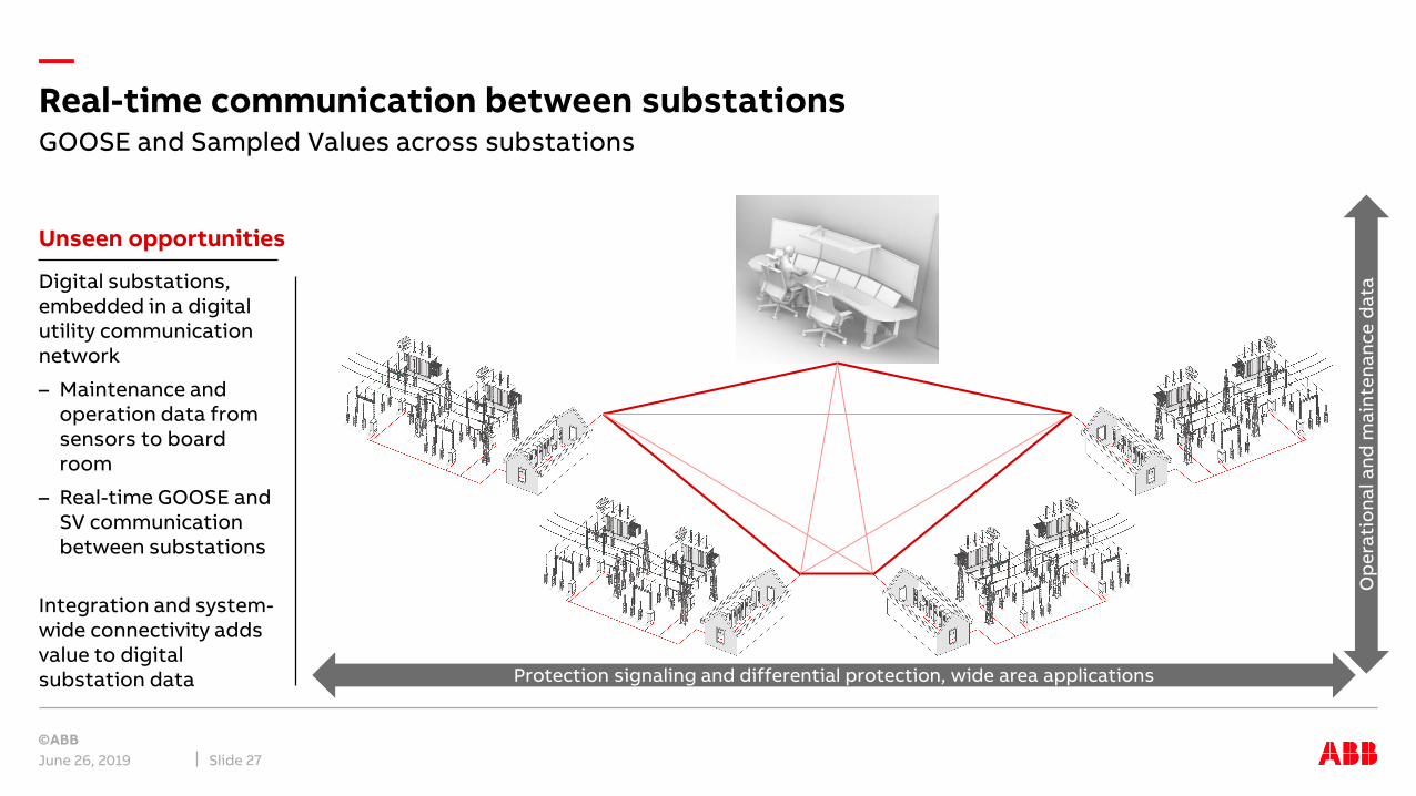
Unseen opportunities
Digital substations, embedded in a digital utility communication network
– Maintenance and operation data from sensors to board room
– Real-time GOOSE and SV communication between substations
Integration and system-wide connectivity adds value to digital substation data
GOOSE and Sampled Values across substations
Protection signaling and differential protection, wide area applications
Op
era
tio
na
l an
d m
ain
ten
an
ce
da
ta

—Digital substations with conventional line protection
June 26, 2019 Slide 28
Distance protection Differential protection
Protection IEDs act as “protocol converter” between IEC 61850 and wires or C37.94
TPE
BIEDSAM600
MU
PDIS, 21
MUX
BIEDSAM600
MU
PDIS, 21
MUX TPE
Process bus(GOOSE & SV)
BIEDSAM600
MU
MUX
BIEDSAM600
MU
MUX
Process bus(GOOSE & SV)
C37.94 C37.94
PDIF, 87 PDIF, 87

—Digital substations with digital line protection
June 26, 2019 Slide 29
Distance protection Differential protection
Increased performance and flexibility with simpler system design
ABB FOX612/615 MUX with IEC 61850 GOOSE and Sampled Values
BIEDSAM600
MU
PDIS, 21
MUX
BIEDSAM600
MU
PDIS, 21
MUX
Process bus(GOOSE & SV)
BIEDSAM600
MU
PDIF, 87
MUX
BIEDSAM600
MU
PDIF, 87
MUX
Process bus(GOOSE & SV)
SV (& GOOSE) SV (& GOOSE)GOOSE GOOSE

—Comparison
June 26, 2019 Slide 30
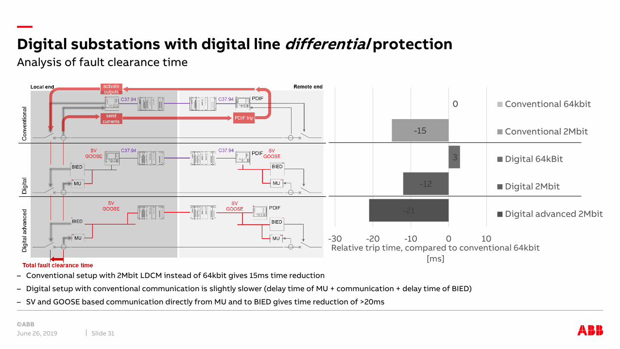
Comparison of 3 scenarios:
– Conventionalwith C37.94 between PDIF IEDs
– Digitalwith MUs, sampled values & GOOSE but C37.94 between IEDs
– Digital advancedwith sampled values and GOOSE directly between process and remote end IED
Line differential
Local end Remote end
BIED
SAM600
MU
C37.94SVGOOSE
C37.94 SVGOOSE
C37.94 C37.94
SVGOOSE
SVGOOSE
BIED
SAM600
MU
BIED
SAM600
MU
BIED
SAM600
MU
PDIF
Co
nv
en
tio
na
lD
igit
al
Dig
ita
l ad
va
nc
ed
Total fault clearance time
PDIF
PDIF
send currents
PDIF trip
activate outputs
—
– Conventional setup with 2Mbit LDCM instead of 64kbit gives 15ms time reduction
– Digital setup with conventional communication is slightly slower (delay time of MU + communication + delay time of BIED)
– SV and GOOSE based communication directly from MU and to BIED gives time reduction of >20ms
Digital substations with digital line differential protection
June 26, 2019 Slide 31
Analysis of fault clearance time
-21
-12
3
-15
0
-30 -20 -10 0 10Relative trip time, compared to conventional 64kbit
[ms]
Conventional 64kbit
Conventional 2Mbit
Digital 64kBit
Digital 2Mbit
Digital advanced 2Mbit

—Real-time analog and binary data across substations
June 26, 2019 Slide 32
New application possibilities
Being able to distribute real-time measurements and commands across wide area networks, opens unseen opportunities
For example
– Automatic voltage regulationby using remote measurements to optimally adjust tap-change settings
– Integration of renewable generationshare measurements between grid connection points and remote generation locations, e.g. off-shore wind turbines
– Power System Protection Scheme (PSPS) or Remedial Action Scheme (RAS)using real-time measurements to perform system wide protection functions
– …
IEC 61850 GOOSE and Sampled Values
BIEDSAM600
MU
MUX
BIEDSAM600
MU
MUX
Process bus(GOOSE & SV)
SV (& GOOSE)
