steering system - cargeek.ir · 8. bleed the system. power steering fluid type : psf-3 total...
TRANSCRIPT

Steering SystemGENERAL
STEERING COLUMN & SHAFTSTEERING COLUMN/SHAFT
MECHANICAL POWER STEERING SYS-TEM
POWER STEERING GEAR BOXPOWER STEERING HOSESPOWER STEERING OIL PUMP
EPS (ELECTRONIC POWER STEERING)SYSTEM
www.cargeek.ir
www.cargeek.ir

ST -2 STEERING SYSTEM
GENERALSPECIFICATIONS E52E8BEB
Item SpecificationsShaft and joint type Collapsible, crossjoint with tilt column
Steering gear type Rack and pinion
Rack stroke mm 146
Tilt stroke(Manual/Power) ±7
Column and shaft
Tele stroke(Manual/Power) 30mm
Type Vane type
Displacement 9.6 cc/rev
Oil pump 3.3L/3.8L
Relief pressure 100 ± 4 kgf/
Inner 37.68 ± 2
Outer 30.71
Steering angle
Tie rod end ball joint starting torque 30kg·cm or less
www.cargeek.ir
www.cargeek.ir

GENERAL ST -3
TIGHTENING TORQUE EC7E7013
Items Nm kgf·m lb-ftSteering column to column membermounting (upper) 13 ~ 18 1.3 ~ 1.8 9.4 ~ 13
Steering column to column membermounting (lower) 13 ~ 18 1.3 ~ 1.8 9.4 ~ 13
Steering column dust cover mounting bolt 13 ~ 18 1.3 ~ 1.8 9.4 ~ 13
Steering wheel lock nut 40 ~ 50 4 ~ 5 28.9 ~ 36.1
Joint assembly(upper) 15 ~ 20 1.5 ~ 2.0 10.8 ~ 14.4
Steeringcolumn andshaft
Joint assembly(lower) 18 ~ 25 1.8 ~ 2.5 13 ~ 18
Wheel nut 90 ~ 110 9 ~ 11 66 ~ 81
Pressure hose to gear box 12 ~ 18 1.2 ~ 1.8 8.6 ~ 13
Return tube to gear box 12 ~ 18 1.2 ~ 1.8 8.6 ~ 13
Tie rod end lock nut 50 ~ 55 5.0 ~ 5.5 36.1 ~ 39.7
Pinion and valve assembly to self locking nut 20 ~ 30 2 ~ 3 14.4 ~ 21.6
Yoke plug lock nut 50 ~ 70 5 ~ 7 36.1 ~ 50.6
Tie rod end self locking nut 24 ~ 34 2.4 ~ 3.4 17.3 ~ 24.5
Mounting bracket to crossmember 140 ~ 160 14 ~ 16 101 ~ 118
Steering gearbox
Steering gear box Mounting 45 ~ 55 4.5 ~ 5.5 33 ~ 39.7
Pressure hose to oil pump 55 ~ 65 5.5 ~ 6.5 39.7 ~ 47
Oil pump mounting bolt [3.3L],[3.8L] 35 ~ 55 3.5 ~ 5.5 25.3 ~ 39.7
Pump cover to pump body 18 ~ 22 1.8 ~ 2.2 13 ~ 15.9
Suction connector to oil pump body 6 ~ 10 0.6 ~ 1 4.3 ~ 7.2
Oil pump
Flow control valve connector to pump body 55 ~ 65 5.5 ~ 6.5 39.7 ~ 47
Oil reservoir bracket mounting bolt 4 ~ 6 0.4 ~ 0.6 2.8 ~ 4.3
Cooler tube clamp mounting bolt 4 ~ 6 0.4 ~ 0.6 2.8 ~ 4.3
Tube clip and tube bracket 4 ~ 6 0.4 ~ 0.6 2.8 ~ 4.3
Pressure hose bracket mounting bolt 4 ~ 6 0.4 ~ 0.6 2.8 ~ 4.3
Steering hosesand oil reservoir
Hose clamp 4 ~ 6 0.4 ~ 0.6 2.8 ~ 4.3
LUBRICANTS
Items Specified lubircant QuantitySteering column bearing Multipurpose grease SAE J310a, NLGI No.2 As required
Steering gear box rack, piniongear part Multipurpose grease SAE J310a, NLGI No.2 As required
Bellows Silicone grease As required
Oil pump Power steering fluid (PSF-3) As required
Power steering fluid Power steering fluid (PSF-3) 1.0 lit
Tie rod end ball joint SUNLIGHT MB-2 4g
www.cargeek.ir
www.cargeek.ir

ST -4 STEERING SYSTEM
SPECIAL TOOLS E215AE3F
Tool (Number and Name) Illustration Use09222-32100Valve stem oil seal installer
EPRF001B
Installation of the oil pump oil seal
09555-21000Bar
EPRF001D
Removal and installation of the oil seal(Use with 09573-33100, 09573-33000,09573-21000)
09561-11001Steering wheel puller
EPRF001E
Removal of steering wheel
09568-4A000Tie rod end puller
KPRE103I
Separation of the tie rod end bail joint
09572-21000Oil pressure gauge
EPRF001F
Measurement of the oil pressure(Use with 09572-22100, 09572-21200)
www.cargeek.ir
www.cargeek.ir

GENERAL ST -5
09572-21200Oil pressure gauge adapter
EPRF001G
Measurement of the oil pressure(Use with 09572-21000, 09572-22100)
09572-22100Oil pressure gauge adapter
EPRF001H
Measurement of the oil pressure(Use with 09572-21000, 09572-21200)
09573-21100Oil seal installer
EPRF001I
Installation of the back up washer and oil seal(Use with 09753-21000,09573-33100,09555-21000)
09573-33100Oil seal guide
EPRF001K
Removal and installation of the oil seal(Use with 09573-21000, 09573-33000,09555-21000)
09432-21600Braring installer
APJF001K
Installing the pinion gear bearing
www.cargeek.ir
www.cargeek.ir

ST -6 STEERING SYSTEM
09434-14200Counter shaft bearing installer
APJF001M
Installing the gear box oil seal
09565-11100Preload socket
APJF001A
Measuring the pinion shaft preload
www.cargeek.ir
www.cargeek.ir

GENERAL ST -7
TROUBLESHOOTING E80E87DD
Symptom Probable cause RemedyLoose yoke plug Retighten
Loose steering gear mounting bolts Retighten
Excessive play insteering
Loose or worn tie rod end Retighten or replace as necessary
V-belt slippage Readjust
Damaged V-belt Replace
Low fluid level Replenish
Air in the fluid Bleed air
Twisted or damaged hoses Correct the routing or replace
Insufficient oil pump pressure Repair or replace the oil pump
Sticky flow control valve Replace
Excessive internal oil pump leakage Replace the damaged parts
Excessive oil leaks from rack andpinion in gear box Replace the damaged parts
Steering wheeloperation is notsmooth (Insufficientpower assist)
Distorted or damaged gear box orvalve body seals Replace
Excessive turning resistance of tierod end Replace
Yoke plug excessively tight Adjust
Tie rod and/or ball joint cannot turn smoothly Replace
Loose mounting of gear box mounting bracketWorn steering shaft joint and/or Retighten
Worn steering shaft joint and/or body grommet Correct or replace
Distorted rack Replace
Damaged pinion bearing Replace
Twisted or damaged hoses Reposition or replace
Damaged oil pressure control valve Replace
Steering wheel doesnot return properly
Damaged oil pump input shaft bearing Replace
Noise Hissing Noise in Steering GearThere is some noise with all power steering systems. One of the most common is ahissing sound when the steering wheel is turned and the car is not moving. This noisewill be most evident when turning the wheel while the brakes are being applied. Thereis no relationship between this noise and steering performance. Do not replace thevalve unless the "hissing" noise becomes extreme. A replaced valve will also makea slight noise, and is not always a solution for the condition.
Interference with hoses from vehicle body Reposition
Loose gear box bracket Retighten
Loose tie rod end and/or ball joint Retighten
Rattling or chuckingnoise in the rackand pinion
Worn tie rod and/or ball joint Replace
Low fluid level Replenish
Air in the fluid Bleed air
Noise in the oil pump
Loose pump mounting bolts Retighten
www.cargeek.ir
www.cargeek.ir

ST -8 STEERING SYSTEM
SERVICE ADJUSTMENTPROCEDURE EF4B5EEB
CHECKING STEERING WHEEL FREE PLAY
1. Start the engine and with the steering wheel in thestraight ahead position.
2. Measure the play while turning the steering wheel tothe left and right.
Standard value :Steering wheel free play : 30 mm (1.1 in)
KPBF010C
3. If the play exceeds the standard value, inspect theconnection between the steering shaft and tie rodends.
CHECKING STEERING ANGLE
1. Place the front wheel on a turning radius gauge andmeasure the steering angle.
Standard value :Wheel angleInside wheel 39.17 ±2Outside wheel 31.56
2. If the measured value is not within the standard value,adjust the toe and inspect again.
EPRF010A
CHECKING THE TIE ROD END BALL JOINTSTARTING TORQUE
1. Disconnect tie rod and knuckle with the special tool(09568-4A000).
09568-4A000
KPBF010E
www.cargeek.ir
www.cargeek.ir
GENERAL ST -9
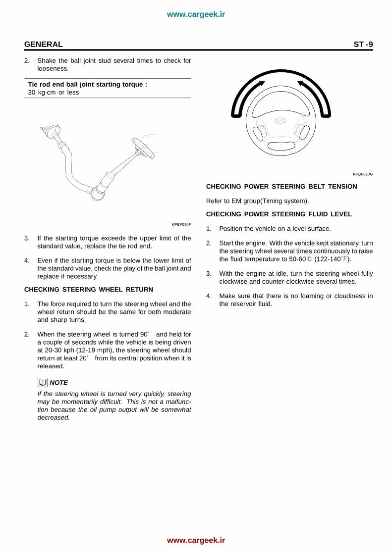
2. Shake the ball joint stud several times to check forlooseness.
Tie rod end ball joint starting torque :30 kg·cm or less
KPBF010F
3. If the starting torque exceeds the upper limit of thestandard value, replace the tie rod end.
4. Even if the starting torque is below the lower limit ofthe standard value, check the play of the ball joint andreplace if necessary.
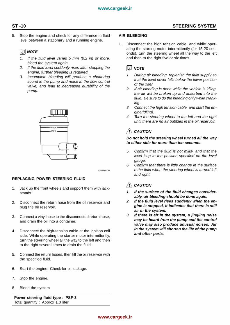
CHECKING STEERING WHEEL RETURN
1. The force required to turn the steering wheel and thewheel return should be the same for both moderateand sharp turns.
2. When the steering wheel is turned 90˚ and held fora couple of seconds while the vehicle is being drivenat 20-30 kph (12-19 mph), the steering wheel shouldreturn at least 20˚ from its central position when it isreleased.
NOTEIf the steering wheel is turned very quickly, steeringmay be momentarily difficult. This is not a malfunc-tion because the oil pump output will be somewhatdecreased.
KPBF010G
CHECKING POWER STEERING BELT TENSION
Refer to EM group(Timing system).
CHECKING POWER STEERING FLUID LEVEL
1. Position the vehicle on a level surface.
2. Start the engine. With the vehicle kept stationary, turnthe steering wheel several times continuously to raisethe fluid temperature to 50-60 (122-140).
3. With the engine at idle, turn the steering wheel fullyclockwise and counter-clockwise several times.
4. Make sure that there is no foaming or cloudiness inthe reservoir fluid.
www.cargeek.ir
www.cargeek.ir
ST -10 STEERING SYSTEM
5. Stop the engine and check for any difference in fluidlevel between a stationary and a running engine.
NOTE1. If the fluid level varies 5 mm (0.2 in) or more,
bleed the system again.2. If the fluid level suddenly rises after stopping the
engine, further bleeding is required.3. Incomplete bleeding will produce a chattering
sound in the pump and noise in the flow controlvalve, and lead to decreased durability of thepump.
MAXMIN
KPBF010H
REPLACING POWER STEERING FLUID
1. Jack up the front wheels and support them with jack-stands.
2. Disconnect the return hose from the oil reservoir andplug the oil reservoir.
3. Connect a vinyl hose to the disconnected return hose,and drain the oil into a container.
4. Disconnect the high-tension cable at the ignition coilside. While operating the starter motor intermittently,turn the steering wheel all the way to the left and thento the right several times to drain the fluid.
5. Connect the return hoses, then fill the oil reservoir withthe specified fluid.
6. Start the engine. Check for oil leakage.
7. Stop the engine.
8. Bleed the system.
Power steering fluid type : PSF-3Total quantity : Approx 1.0 liter
AIR BLEEDING
1. Disconnect the high tension cable, and while oper-ating the starting motor intermittently (for 15-20 sec-onds), turn the steering wheel all the way to the leftand then to the right five or six times.
NOTE1. During air bleeding, replenish the fluid supply so
that the level never falls below the lower positionof the filter.
2. If air bleeding is done while the vehicle is idling,the air will be broken up and absorbed into thefluid. Be sure to do the bleeding only while crank-ing.
3. Connect the high tension cable, and start the en-gine(idling).
4. Turn the steering wheel to the left and the rightuntil there are no air bubbles in the oil reservoir.
CAUTIONDo not hold the steering wheel turned all the wayto either side for more than ten seconds.
5. Confirm that the fluid is not milky, and that thelevel isup to the position specified on the levelgauge.
6. Confirm that there is little change in the surfaceo the fluid when the steering wheel is turned leftand right.
CAUTION1. If the surface of the fluid changes consider-
ably, air bleeding should be done again.2. If the fluid level rises suddenly when the en-
gine is stopped, it indicates that there is stillair in the system.
3. If there is air in the system, a jingling noisemay be heard from the pump and the controlvalve may also produce unusual noises. Airin the system will shorten the life of the pumpand other parts.
www.cargeek.ir
www.cargeek.ir

GENERAL ST -11
MAX
5mm
MIN
KPBF010J
OIL PUMP PRESSURE TEST (OIL PUMP RELIEFPRESSURE)
1. Disconnect the pressure hose from the oil pump.Connect the special tool between the oil pump andpressure hose as illustrated.
2. Bleed the air, and then start the engine and turn thesteering wheel several times so that the fluid temper-ature rises to approximately 50 (122).
3. Set the engine speed to 1,000 rpm.
4. Close the shut-off valve of the special tool and mea-sure the fluid pressure to confirm that it is within therange.
standard vaule :Relief pressure: 90 +3/-2 kgf/
CAUTIONDon’ t keep the shut-off valve on the pressuregauge closed for longer than seconds.
Temperturegauge
Oil pump
Pressurehose
Oil pressure gauge(09572-21000)
Adapter(09572-21200,09572-22100)
Oil pressuregauge adapter(09572-22100)
Oil pumprelief presure
Reservor
Shut-off valve(close)
EPRF002B
5. Remove the special tools, and tighten the pressurehose to the specified torque.
Tightening Torque Nm(kgf·m, lb-ft) :55 ~ 65(5.5 ~ 6.5, 39.7 ~ 47)
6. Bleed the system.
www.cargeek.ir
www.cargeek.ir
ST -12 STEERING SYSTEM
STEERING COLUMN &SHAFT
STEERING COLUMN/SHAFT
COMPONENTS EE8A2FB4
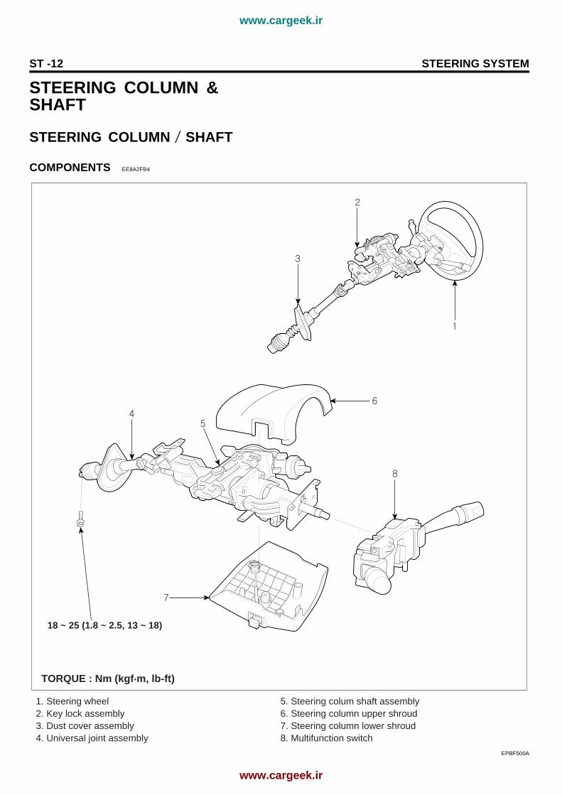
1. Steering wheel 2. Key lock assembly 3. Dust cover assembly4. Universal joint assembly
5. Steering colum shaft assembly6. Steering column upper shroud 7. Steering column lower shroud8. Multifunction switch
TORQUE : Nm (kgf.m, lb-ft)
18 ~ 25 (1.8 ~ 2.5, 13 ~ 18)
EPBF500A
www.cargeek.ir
www.cargeek.ir
STEERING COLUMN & SHAFT ST -13
REMOVAL E8272C54
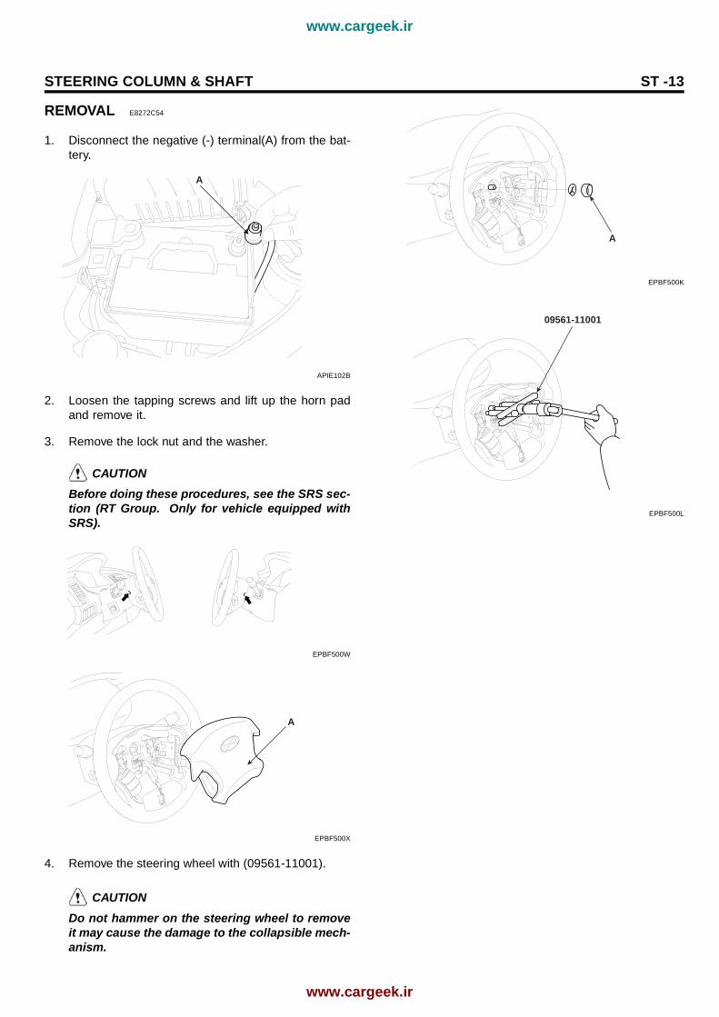
1. Disconnect the negative (-) terminal(A) from the bat-tery.
A
APIE102B
2. Loosen the tapping screws and lift up the horn padand remove it.
3. Remove the lock nut and the washer.
CAUTIONBefore doing these procedures, see the SRS sec-tion (RT Group. Only for vehicle equipped withSRS).
EPBF500W
A
EPBF500X
4. Remove the steering wheel with (09561-11001).
CAUTIONDo not hammer on the steering wheel to removeit may cause the damage to the collapsible mech-anism.
A
EPBF500K
09561-11001
EPBF500L
www.cargeek.ir
www.cargeek.ir

ST -14 STEERING SYSTEM
5. Remove the lower cover(A).
[LHD]
A
EPBF500M
[RHD]
A
EPBF500N
6. Remove the steering column lower and uppershrouds.
B
A
C
EPBF500O
www.cargeek.ir
www.cargeek.ir

STEERING COLUMN & SHAFT ST -15
7. Disconnect the connectors and remove the multifunc-tion switch.
AB
EPBF500P
8. Remove the bolts securing the coupling and universaljoint. Pull out the universal joint from the gear box.
[LHD]
A
KHBF140F
[RHD]
A
EPBF500Q
9. Remove the dust cover mounting bolts.
[LHD]
A
KPBF101H
[RHD]
EPRF700G
10. Remove the steering column mounting bolts (4bolts).
A
B
KPBF101I
11. Remove the steering column and shaft with the uni-versal joint and cover.
www.cargeek.ir
www.cargeek.ir

ST -16 STEERING SYSTEM
DISASSEMBLY EB261A91
KEY LOCK ASSEMBLY
1. If it is necessary to remove the key lock assembly(A),use a punch to make a groove on the head of thespecial bolt(B), and then use a screwdriver to removethe key lock assembly mounting bracket(C).
C
A
B
KPBF111A
2. Disassemble the key lock assembly(A) from the steer-ing column and shaft assembly(B).
B
A
KPBF111B
3. Reassembly is reverse of disassembly.
UNIVERSAL JOINT ASSEMBLY
1. Remove the bolt(A) connecting the universal joint as-sembly(B) and the steering column and shaft assem-bly(C).
C
B
A
KPBF111C
2. Remove the universal joint assembly(A) from thesteering column and shaft assembly(B).
B
A
KPBF111D
3. Reassembly is reverse of disassembly.
www.cargeek.ir
www.cargeek.ir
STEERING COLUMN & SHAFT ST -17
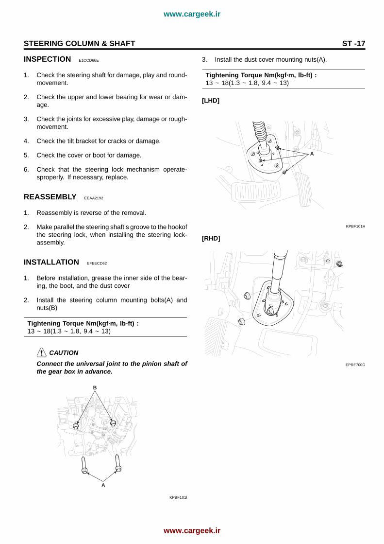
INSPECTION E1CCD66E
1. Check the steering shaft for damage, play and round-movement.
2. Check the upper and lower bearing for wear or dam-age.
3. Check the joints for excessive play, damage or rough-movement.
4. Check the tilt bracket for cracks or damage.
5. Check the cover or boot for damage.
6. Check that the steering lock mechanism operate-sproperly. If necessary, replace.
REASSEMBLY EEAA2192
1. Reassembly is reverse of the removal.
2. Make parallel the steering shaft’s groove to the hookofthe steering lock, when installing the steering lock-assembly.
INSTALLATION EFEECD62
1. Before installation, grease the inner side of the bear-ing, the boot, and the dust cover
2. Install the steering column mounting bolts(A) andnuts(B)
Tightening Torque Nm(kgf·m, lb-ft) :13 ~ 18(1.3 ~ 1.8, 9.4 ~ 13)
CAUTIONConnect the universal joint to the pinion shaft ofthe gear box in advance.
A
B
KPBF101I
3. Install the dust cover mounting nuts(A).
Tightening Torque Nm(kgf·m, lb-ft) :13 ~ 18(1.3 ~ 1.8, 9.4 ~ 13)
[LHD]
A
KPBF101H
[RHD]
EPRF700G
www.cargeek.ir
www.cargeek.ir

ST -18 STEERING SYSTEM
4. Install the connecting bolt(A) between the universaljoint and the pinion shaft.
Tightening Torque Nm(kgf·m, lb-ft) :18 ~ 25(1.8 ~ 2.5, 13 ~ 18)
[LHD]
A
KHBF140F
[RHD]
A
EPBF500Q
5. Install the multifunction switch(B) mounting screws(A)and the connectors.
AB
EPBF500P
6. Install the steering column lower(A) and upper(B)shrouds.
B
A
C
EPBF500O
www.cargeek.ir
www.cargeek.ir

STEERING COLUMN & SHAFT ST -19
7. Install the crush pad lower cover(A).
[LHD]
A
EPBF500Y
[RHD]
A
EPBF500Z
8. Install the steering wheel locking nut(A).
Tightening Torque Nm(kgf·m, lb-ft) :40 ~ 50(4 ~ 5, 28.9 ~ 36.1)
NOTECheck that the front wheels is in the right direction inadvance.
A
EPBF500K
9. Install the two steering wheel cover(A) bolts by usingthe hexagon wrench.
A
EPBF500X
EPBF500W
10. Connect the negative (-) terminal(A) to the battery.
A
APIE102B
www.cargeek.ir
www.cargeek.ir

ST -20 STEERING SYSTEM
MECHANICAL POWERSTEERING SYSTEMCOMPONENTS E401C9A1
1. Bellows2. Rack housing3. Feed tube
4. Valve body assembly5. Tie rod assembly6. Lock nut
2
5
1
4
6
1
2
34
5
6
3
[LHD]
[RHD]
EPBF500V
www.cargeek.ir
www.cargeek.ir
MECHANICAL POWER STEERING SYSTEM ST -21
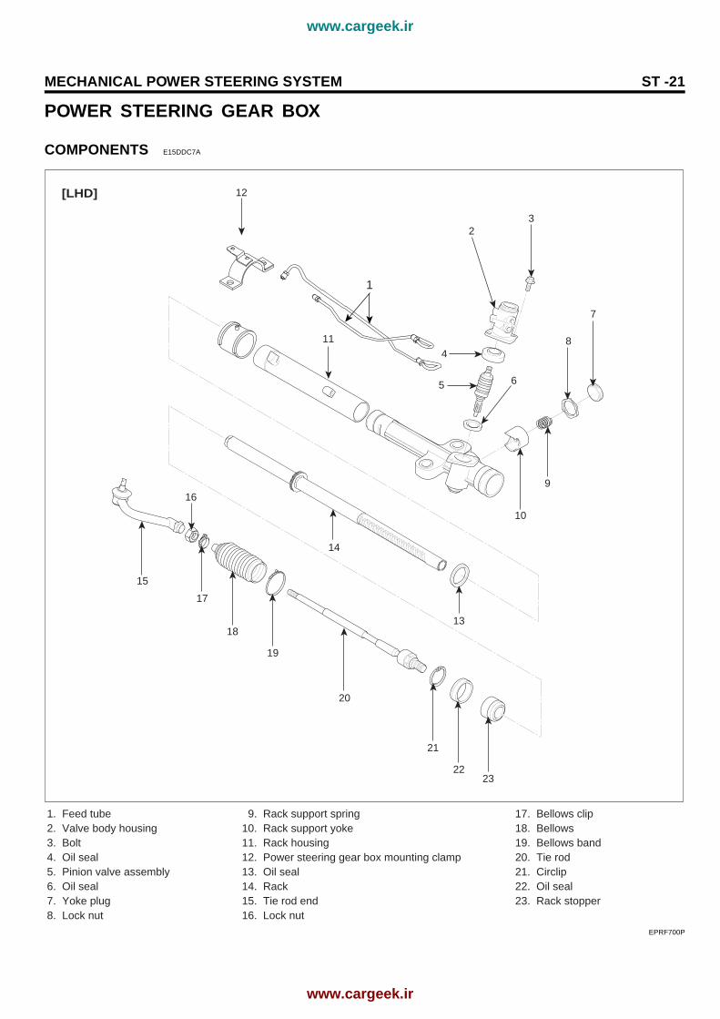
POWER STEERING GEAR BOX
COMPONENTS E15DDC7A
14
15
16
17
18
19
20
21
2223
1. Feed tube2. Valve body housing3. Bolt4. Oil seal5. Pinion valve assembly6. Oil seal7. Yoke plug8. Lock nut
9. Rack support spring10. Rack support yoke11. Rack housing12. Power steering gear box mounting clamp13. Oil seal14. Rack15. Tie rod end16. Lock nut
17. Bellows clip18. Bellows19. Bellows band20. Tie rod21. Circlip22. Oil seal23. Rack stopper
23
7
84
11
12
6
9
10
5
1
13
[LHD]
EPRF700P
www.cargeek.ir
www.cargeek.ir
ST -22 STEERING SYSTEM
14
15
16
17
18
19
20
21
2223
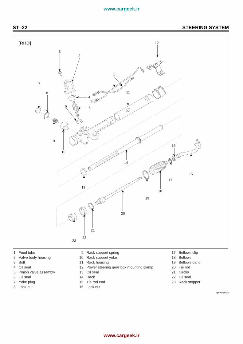
1. Feed tube2. Valve body housing3. Bolt4. Oil seal5. Pinion valve assembly6. Oil seal7. Yoke plug8. Lock nut
9. Rack support spring10. Rack support yoke11. Rack housing12. Power steering gear box mounting clamp13. Oil seal14. Rack15. Tie rod end16. Lock nut
17. Bellows clip18. Bellows19. Bellows band20. Tie rod21. Circlip22. Oil seal23. Rack stopper
23
7
84
11
12
6
9
10
5
1
13
[RHD]
EPRF700Q
www.cargeek.ir
www.cargeek.ir

MECHANICAL POWER STEERING SYSTEM ST -23
REMOVAL E54305AB
1. Loosen the wheel nuts slightly.Raise the front of the vehicle, and make sure it issecurely supported.
2. Remove the front wheel and tire(A) from front hub(B).
EIRF101A
CAUTIONBe careful not to damage the hub bolts(C) thenremove the front wheel and tire(A).
3. Drain the power steering fluid.
4. Disconnect the pressure hose and the retrun tube.
B
A
KPBF211A
5. Remove the pressure sensor connector(A) from thepressure hose
A
KPBF222A
6. Remove the nut(B) from the stabilizer bar link(A).
A
B
KHRE110B
7. Using the specil tool(09568-4A000) disconnect the tierod end from the knuckle arm.
EPBF500G
www.cargeek.ir
www.cargeek.ir

ST -24 STEERING SYSTEM
09568-4A000
KHBF105B
8. Remove the lower arm mounting bolts(A).
A
KHBF140D
9. Remove the front fork and the knuckle ball joint fromthe front lower arm.
A
KHBF140E
CAUTIONBe careful not to damage to the aluminium lowerarm.
10. Remove the joint assembly connecting bolt.
[LHD]
A
KHBF140F
[RHD]
A
EPBF500Q
11. Remove the connecting bolts of front and rear rollstopper.
A
B
KHBF301A
www.cargeek.ir
www.cargeek.ir
MECHANICAL POWER STEERING SYSTEM ST -25
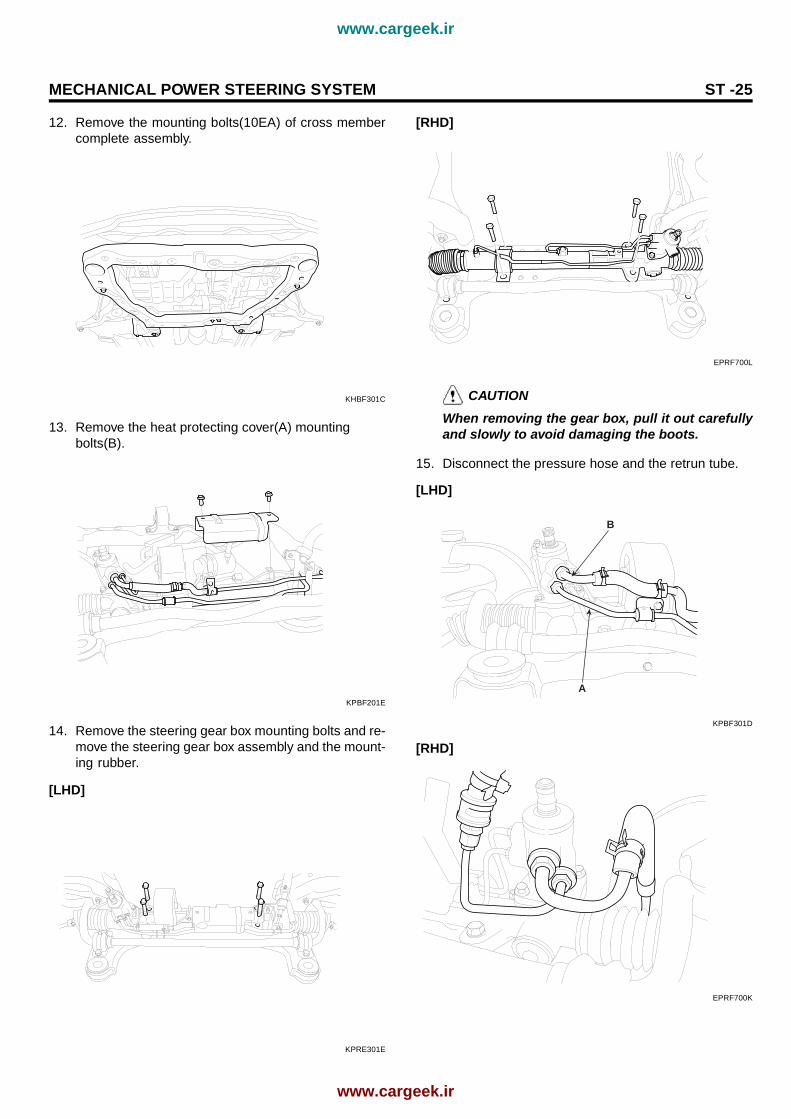
12. Remove the mounting bolts(10EA) of cross membercomplete assembly.
KHBF301C
13. Remove the heat protecting cover(A) mountingbolts(B).
KPBF201E
14. Remove the steering gear box mounting bolts and re-move the steering gear box assembly and the mount-ing rubber.
[LHD]
KPRE301E
[RHD]
EPRF700L
CAUTIONWhen removing the gear box, pull it out carefullyand slowly to avoid damaging the boots.
15. Disconnect the pressure hose and the retrun tube.
[LHD]
B
A
KPBF301D
[RHD]
EPRF700K
www.cargeek.ir
www.cargeek.ir

ST -26 STEERING SYSTEM
DISASSEMBLY E6CAB1AD
1. Remove the tie rod end(B) from the tie rod(A).
BA
KPBF202A
2. Remove the dust cover(B) from the ball joint(A).
A
B
EPBF500H
3. Remove the bellows band(A).
A
KPBF006F
4. Remove the bellows clip(A).
EPKE013I
5. Pull the bellows out toward the tie rod.
NOTECheck for rust on the rack when the bellows are re-placed.
6. Remove the feed tube(A) from the rack housing.
APHE006H
7. While moving the rack slowly, drain the fluid from ther-ack housing.
www.cargeek.ir
www.cargeek.ir

MECHANICAL POWER STEERING SYSTEM ST -27
8. Unstake the tab washer(A) which fixes the tie rod(B)and rack(C) with a chisel.
EPKE037A
9. Remove the tie rod(B) from the rack(A).
CAUTIONRemove the tie rod(B) from the rack(A), takingcarenot to twist the rack.
B
A
KPBF006J
10. Remove the yoke plug locking nut(A).
A
KPBF006K
11. Remove the yoke plug(B) with a 14mm socket(A).
A
B
KPBF006L
12. Remove the lock nut(D), yoke plug(C), rack supportspring(B) and rack support yoke(A) from the gear box.
APJF005L
www.cargeek.ir
www.cargeek.ir

ST -28 STEERING SYSTEM
13. When the end of the circlip comes out of the notched-hole of the housing rack cylinder, turn the rack stoppercounterclockwise and remove the circlip.
CAUTIONBe careful not to damage the rack.
EPKE013Q
14. When the end of the circlip comes out of the notchedhole of the housing rack cylinder, turn the rack stoppercounterclockwise and remove the circlip.
EPKE013R
CAUTIONBe careful not to damage the rack.
15. Remove the rack bushing and rack from the rackhousing.
16. Remove the O-ring(A) from the rack bushing(B).
EPKE013T
17. Remove the oil seal(B) from the rack bushing(A).
EPKE013U
18. Remove the valve body from the valve body housingwith a soft hammer.
EPKE210A
19. Using the special tool, remove the oil seal and ball-bearing from the valve body housing.
www.cargeek.ir
www.cargeek.ir
MECHANICAL POWER STEERING SYSTEM ST -29
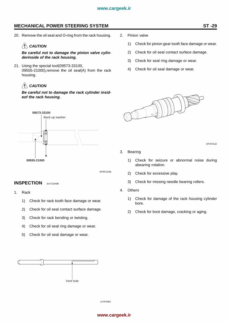
20. Remove the oil seal and O-ring from the rack housing.
CAUTIONBe careful not to damage the pinion valve cylin-derinside of the rack housing.
21. Using the special tool(09573-33100,09555-21000),remove the oil seal(A) from the rackhousing.
CAUTIONBe careful not to damage the rack cylinder insid-eof the rack housing.
09555-21000
A
09573-33100
Back-up washer
EPRF210B
INSPECTION EA7CDA9B
1. Rack
1) Check for rack tooth face damage or wear.
2) Check for oil seal contact surface damage.
3) Check for rack bending or twisting.
4) Check for oil seal ring damage or wear.
5) Check for oil seal damage or wear.
Vent hole
LPJF006C
2. Pinion valve
1) Check for pinion gear tooth face damage or wear.
2) Check for oil seal contact surface damage.
3) Check for seal ring damage or wear.
4) Check for oil seal damage or wear.
APJF013Z
3. Bearing
1) Check for seizure or abnormal noise duringabearing rotation.
2) Check for excessive play.
3) Check for missing needle bearing rollers.
4. Others
1) Check for damage of the rack housing cylinderbore.
2) Check for boot damage, cracking or aging.
www.cargeek.ir
www.cargeek.ir

ST -30 STEERING SYSTEM
REASSEMBLY EA4ABAC8
1. Apply the specified fluid to the entire surface of therack oil seal.
Recommended fluid : PSF-3
2. Install the backup washer and oil seal(A) to the spec-ified position in the rack housing.
09573-33100
KPBF007F
3. Apply the specified fluid to the entire surface of therack bushing oil seal.
Recommended fluid : PSF-3
4. Install the oil seal(A) in the rack bushing(B).
EPKE230B
5. Apply the specified fluid to the entire surface of theO-ring and install it in the rack bushing.
6. Apply the specified grease to the rack teeth.
Recommended greaseMultipurpose grease SAE J310a NLGI No.2
NOTEDo not plug the vent hole(A) in the rack with grease.
APJF014E
7. Insert the rack(A) into the rack housing(B) and installthe rack bushing(C).
EPKE230I
www.cargeek.ir
www.cargeek.ir

MECHANICAL POWER STEERING SYSTEM ST -31
8. Push in the rack stopper until the circlip groove of therack stopper is aligned with the notched hole of therack housing. Then, install the circlip while turningthe rack stopper.
CAUTIONThe circlip should not be visible through thenotched hole of the rack housing.
Slot
circlip position
EPBF500C
9. Using special Tool(09432–21600), install the oil sealand the ball bearing in the valve body(A).
APGE008G
10. After applying the specified fluid and grease to thepinion valve assembly(A), install it in the rack housingassembly.
EPKE230E
11. After applying the specified fluid to the oil seal, install itinthe rack housing and fix the valve body assembly(A)and O-ring in the gear box(B).
APHE007F
www.cargeek.ir
www.cargeek.ir

ST -32 STEERING SYSTEM
12. Install the rack support yoke(A), rack supportspring(B), yoke plug(C) and lock nut(D) in the order-shown in the illustration. Apply semi-drying sealanttothe threaded section of the yoke plug before instal-lation.
APJF005L
13. With the rack placed in the center position, attach theyoke plug to the rack housing. Tighten the yokeplug to12 Nm (120 kg·cm, 8.9 lb·ft), with a 14mm socket(A).Loosen the yoke plug approximately from 30 to 60and tighten the yoke nut to the specified torque.
Tightening Torque Nm(kgf·m, lb-ft) :50 ~ 70(5 ~ 7, 37 ~ 52)
APHE007I
14. Tighten the feed tube(A) to the specified torque andinstall the mounting rubber using adhesive.
APHE006H
15. Apply the specified grease to the bellows mountingposition (fitting groove) of the tie rod.
Recommended grease : Silicone grease
APGE008C
16. Install the new attaching band to the bellows.
NOTEWhen the bellows are installed, a new band mustbeused.
17. Install the bellows in position, taking care not to twistit.
www.cargeek.ir
www.cargeek.ir

MECHANICAL POWER STEERING SYSTEM ST -33
18. Fill the dust cover inner side and lip with the specifiedgrease, and fix the dust cover in position with the clipring attached in the groove of the tie rod end.
Recommended greaseA : POLY LUB GLY 801K or equivalentB : SHOWA SUNLIGHT MB2 or equivalentDust cover inner side and lip : THREE BOND
EPKE043A
19. Install the tie rod(A) to the tie rod end(B).
BA
KPBF202A
20. Check for total pinion preload.
APHE006B
INSTALLATION E5D30F7E
NOTEBe sure to connect between a tube and a hoseasshown in the illustration.
3+30
APJF009A
1. Installation is reverse of removal.
TIGHTENING TORQUE Nm(kgf·m, lb-ft)Pressure hose to gear box :12~18(1.2~1.8, 8.6~13)Return tube to gear box :12~18(1.2~1.8, 8.6~13)Tie rod end lock nut :50~55(5~5.5, 36.1~39.7)Pinion and valve assembly to self locking nut :20~30(2~3, 14.4~21.6)lock nut :50~70(5~7, 36.1~50.6)Tie rod end self locking nut :24~34(2.4~3.4, 17.3~24.5)Mounting bracket to crossmember :60~80(6~8, 43.3~57.8)
2. After installation, bleed the air in the power steeringsystem(See page ST-10).
www.cargeek.ir
www.cargeek.ir
ST -34 STEERING SYSTEM
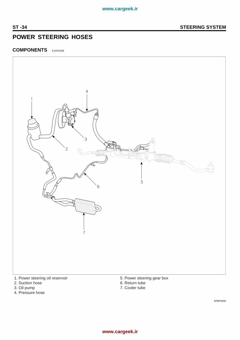
POWER STEERING HOSES
COMPONENTS E1AFD16E
1. Power steering oil reservoir2. Suction hose3. Oil pump4. Pressure hose
5. Power steering gear box6. Return tube7. Cooler tube
EPBF500D
www.cargeek.ir
www.cargeek.ir
MECHANICAL POWER STEERING SYSTEM ST -35
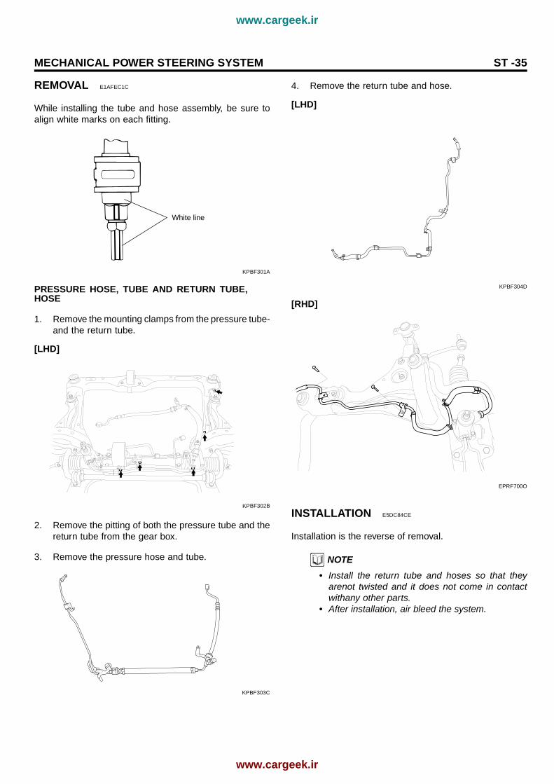
REMOVAL E1AFEC1C
While installing the tube and hose assembly, be sure toalign white marks on each fitting.
White line
KPBF301A
PRESSURE HOSE, TUBE AND RETURN TUBE,HOSE
1. Remove the mounting clamps from the pressure tube-and the return tube.
[LHD]
KPBF302B
2. Remove the pitting of both the pressure tube and thereturn tube from the gear box.
3. Remove the pressure hose and tube.
KPBF303C
4. Remove the return tube and hose.
[LHD]
KPBF304D
[RHD]
EPRF700O
INSTALLATION E5DC84CE
Installation is the reverse of removal.
NOTE• Install the return tube and hoses so that they
arenot twisted and it does not come in contactwithany other parts.
• After installation, air bleed the system.
www.cargeek.ir
www.cargeek.ir
ST -36 STEERING SYSTEM
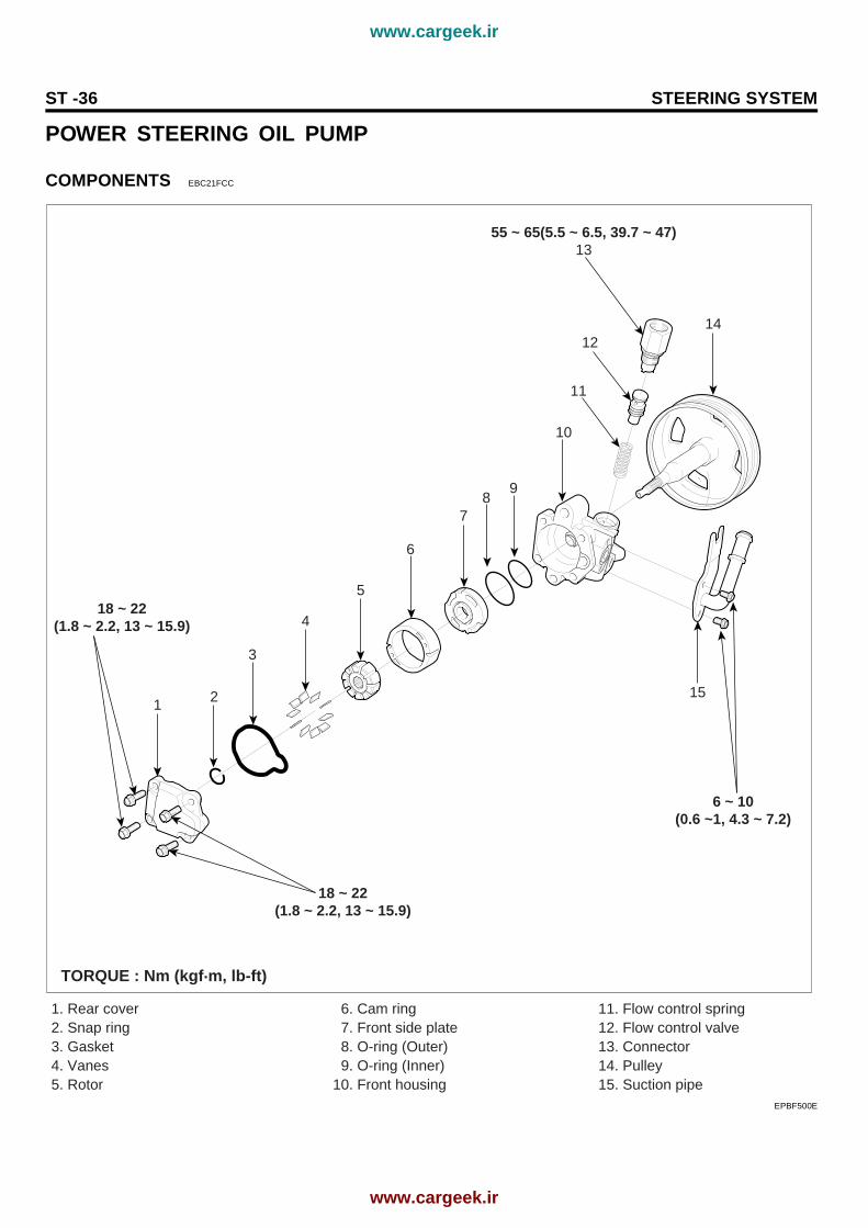
POWER STEERING OIL PUMP
COMPONENTS EBC21FCC
1. Rear cover2. Snap ring3. Gasket4. Vanes5. Rotor
6. Cam ring 7. Front side plate 8. O-ring (Outer) 9. O-ring (Inner)10. Front housing
11. Flow control spring12. Flow control valve13. Connector14. Pulley15. Suction pipe
15
14
7
10
11
12
55 ~ 65(5.5 ~ 6.5, 39.7 ~ 47)13
6
89
5
4
3
21
18 ~ 22(1.8 ~ 2.2, 13 ~ 15.9)
18 ~ 22(1.8 ~ 2.2, 13 ~ 15.9)
6 ~ 10(0.6 ~1, 4.3 ~ 7.2)
TORQUE : Nm (kgf.m, lb-ft)
EPBF500E
www.cargeek.ir
www.cargeek.ir

MECHANICAL POWER STEERING SYSTEM ST -37
REMOVAL E64E3B0B
1. Remove the pressure hose from the oil pump andthe suction hose from the suction pipe, then drain thepowersteering oil.
B
A
KPBF211A
2. Release the tension of the powersteering V-typebeltby lifting the auto-tensioner pulley.
KPBF401B
3. Remove the V-type belt from the pulley of the power-steering oil pump.
4. Remove the powersteering oil pump assembly by re-moving the three bolts as shown below.
A B
KPBF401D
DISASSEMBLY E41A4D99
1. Remove the bolts from the oil pump body, and thenremove the suction pipe and O-ring.
A
KPBF402A
2. Remove the power steering oil pump rear cover(A)and the O-ring(B) by removing the four bolts.
A
B
KPBF412A
www.cargeek.ir
www.cargeek.ir

ST -38 STEERING SYSTEM
3. Remove the cam ring.
A
KPBF412D
4. Remove the cam ring.
A
KPBF412B
5. Remove the rotor and vanes.
A
B
KPBF412C
6. Remove the oil pump side plate.
A
KPBF412E
7. Remove the inner O-ring and outer O-ring.
A
B
KPBF412F
8. Remove the pulley and the shaft(A).
A
KPBF412G
www.cargeek.ir
www.cargeek.ir

MECHANICAL POWER STEERING SYSTEM ST -39
9. Remove the oil seal from the oil pump body.
A
KPBF402D
10. Remove the connector from the oil pump body, andtake out the flow control valve and the flow controlspring.
A
B
C
KPBF412H
11. Remove the O-ring from the connector.
CAUTIONDo not disassemble the flow control valve.
INSPECTION EA05A7C8
1. Check that the flow control valve is not bent.
2. Check the shaft for wear and damage.
3. Check the V-belt for wear and deterioration.
4. Check the grooves of the rotor and vanes for stratifiedabrasion.
5. Check the contact surface of the cam ring and vanesfor stratified abrasion.
6. Check vanes for damage.
7. Check that there is no striped wear in the side plate orcontacting part between the shaft and the pump coversurface.
REASSEMBLY EC78610A
1. Install the flow control spring, the flow control valveand the connector in to the pump body.
A
B
C
KPBF412H
2. Install the oil seal in the pump body by using the spe-cial tool(09222-32100).
09222-32100
KPBF404B
www.cargeek.ir
www.cargeek.ir

ST -40 STEERING SYSTEM
3. Install the pump pulley.
A
KPBF412G
4. Install the outer(A) and inner(B) O-rings
B
A
KPBF414D
5. Install the side plate(A).
A
KPBF412E
6. After inserting the lock pin into the groove of the fronthousing, install the camring attending to the direction.
A
KPBF404F
7. Install the rotor.
A
KPBF414E
8. Install the vanes.
A
KPBF414F
www.cargeek.ir
www.cargeek.ir
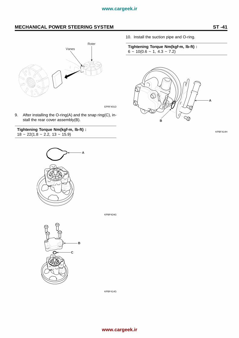
MECHANICAL POWER STEERING SYSTEM ST -41
Roter
Vanes
EPRF401D
9. After installing the O-ring(A) and the snap ring(C), in-stall the rear cover assembly(B).
Tightening Torque Nm(kgf·m, lb-ft) :18 ~ 22(1.8 ~ 2.2, 13 ~ 15.9)
A
KPBF424G
B
C
KPBF414G
10. Install the suction pipe and O-ring.
Tightening Torque Nm(kgf·m, lb-ft) :6 ~ 10(0.6 ~ 1, 4.3 ~ 7.2)
A
B
KPBF414H
www.cargeek.ir
www.cargeek.ir

ST -42 STEERING SYSTEM
INSTALLATION EBFE3F36
1. Install the oil pump to the oil pump bracket.
Tightening Torque Nm(kgf·m, lb-ft) :35 ~ 55(3.5 ~ 5.5, 25.3 ~ 39.7)
A B
KPBF401D
2. Install the "V"-type belt by pulling the auto tensioner.
3. Install the suction hose.
CAUTIONInstall the pressure hose to the oil pump.
4. Install the pressure hose to the oil pump.
Tightening Torque Nm(kgf·m, lb-ft) :55 ~ 65(5.5 ~ 6.5, 39.7 ~ 47)
NOTEInstall the pressure hose being careful so that it doesnot twist and come in contact with other components.
B
A
KPBF211A
5. Add power steering fluid (PSF-3).
6. Air bleed the system.
7. Check the oil pump pressure.
www.cargeek.ir
www.cargeek.ir

EPS (ELECTRONIC POWER STEERING) SYSTEM ST -43
EPS (ELECTRONIC POWERSTEERING) SYSTEMGENERAL E7A2FF5F
The electronic power steering (EPS) system includes the same components of conventional power steering system.
Sloenoid valve
Control unit
Vehicle speed sensor
TPS PUMP
EPRF503A
EPS performs the conventional power steering function in case a failure has occurred in the system. EPS electronicallycontrols the current to the solenoid of by-pass valve by inputting sensor’s signals to control the hydraulic amount incylinder chamber and thereby varying the steering effort versus the hydraulic pressure according to vehicle speed.In addition, it has a solenoid valve on power steering gear box, and a control unit underneath the audio of thecenter facia. To control the oil flow of steering gear box, a solenoid is provided and it functions by the currentfrom control module which receives signals from VSS (Vehicle Speed Sensor) and TPS.
www.cargeek.ir
www.cargeek.ir

ST -44 STEERING SYSTEM
REMOVAL AND INSTALLATION EED98798
The removal and installation procedure is the same as that of conventional power steering system except forthe solenoid valve components and EPS control module. Refer to the following figures.
KPBF500D
www.cargeek.ir
www.cargeek.ir

EPS (ELECTRONIC POWER STEERING) SYSTEM ST -45
ELECTRONIC POWER STEERINGCONTROL MODULE E8F19C24
PIN LAYOUT
PIN NO.
1
2
3
4
5
6
7
8
DESCRIPTION
Sensor signal from vehicle speed sensor
Solenoid
Solenoid
Sensor signal from TPS
Data link connector
IG2
-
Ground
1 2 3 4
5 6 7 8
EPBF500I
www.cargeek.ir
www.cargeek.ir

ST -46 STEERING SYSTEM
CIRCUIT SIAGRAM EAABCA6A
FU
SE
410
A
PA
SS
EN
GE
RC
OM
PA
RT
ME
NT
JUN
CT
ION
BL
OC
K
1M
702
4
1E
39
2E
39
0.5O
0.3O
0.5B
0.3B
0.3R
8
0.3B
0.3L
g0.
3Gr
0.5L
g
0.5O
0.5P
0.5P
0.5P
0.5B
r/B
0.5Y
G20
M70
15E
M21
21E
M01
EN
GIN
EC
OM
PA
RT
ME
NT
JUN
CT
ION
BL
OC
K
25JE
02
83JC
01
18I/P
-A
2027
EM
01
3
0.3Y
0.3O
3C
1253
85C
44
ON
inpu
tS
olen
oid(
-)S
olen
oid(
+)
See
Veh
icle
Spe
ed S
enso
r
Gro
und
Dia
gnos
isV
ehic
le s
peed
in
put
TP
S
EL
EC
RO
NIC
P
OW
ER
S
TE
ER
ING
SO
LE
NO
ID
EL
EC
TR
ON
IC
PO
WE
RS
TE
ER
ING
M
OD
UL
E
JOIN
TC
ON
NE
CT
OR
VE
HIC
LE
SP
EE
D
SE
NS
OR
HO
T IN
ON
See
Pow
erD
istr
ibut
ion
See
Pas
seng
erC
ompa
rtm
ent
Fus
e D
etai
ls
65
13
PC
M1
M05
21JE
01
17
ES
P
CO
NT
RO
LM
OD
UL
E
11E
41
0.5L AB
SC
ON
TR
OL
MO
DU
LE
DA
TA
LIN
KC
ON
NE
CT
OR
11E
22
15M
86
11M
86
PH
OT
O 3
2
PH
OT
O 2
0
PH
OT
O 6
3
PH
OT
O 5
4
PH
OT
O 5
8
PH
OT
O 2
9
PH
OT
O 2
1P
HO
TO
24
PH
OT
O 2
4
PH
OT
O 2
2
PH
OT
O 5
7P
HO
TO
31
PH
OT
O 6
3
PH
OT
O 7
With
AB
SW
ithE
SP
E2RF057A
www.cargeek.ir
www.cargeek.ir

EPS (ELECTRONIC POWER STEERING) SYSTEM ST -47
TROUBLESHOOTING E7A90FA2
NOTEFor checking procedures for each problem, refer tothe flow-chart type of troubleshooting guide on thefollowing page.
Steering effort remains light atmoderate and high speeds
Is the function of the vehiclespeed sensor normal?
Malfunction of E.P.S. solenoidRepair the steering gear box orreplace the E.P.S. solenoid
Repair the connector connectionor repair the harness (Connectthe connector, or repair the harn-ess between the vehicle speedsensor and the control module
Replace vehicle speed sensor
Does the stationary steering ef-fort change within the standard value ?Standard value :E.P.S.2.4 N (2.5 kg, 5.1 lbs) Max.
NOTE1. Check to be made by using the scan tool or test lamp.2. Refer to the circuit diagram for terminal numbers at the harness side of the E.P.S control module.
No
No
Yes
Yes
Trouble symptom 1
EPRF502A
www.cargeek.ir
www.cargeek.ir

ST -48 STEERING SYSTEM
Trouble symptom 2
No flow of solenoid current (largesteering effort required to turn st-eering wheel fully) when the igni-tion switch is at the ON position.
Is fuse for control module powersupply OK?
Harness short-circuit (harness damage, etc.)
Repair the harness or replacethe fuse.
Is the voltage approximately 12Vmeasured between earth andcontrol module harness side con-nector terminal No. 5?
Is there continuity between contr-ol module harness side connec-tor No. 2 and No. 3 ?
SEE NEXT PAGE
Disconnect the connectorof the control module;check with the ignitionswitch at the ON position
Disconnect the connectorfor the E. P. S. solenoidvalve within the enginecompartment and check.
Disconnect the batterynegative (-) terminal andcheck
YesYes
Yes
Yes
Damaged or disconnected wirin-g of harness between fuse andcontrol module terminal No. 5.
Damaged or disconnected wir-ing of harness between controlmodule and E.P.S. solenoid val -ve connector.
NO
NO
NO
NO Is there continuity betweentwoterminals of the connector atthe steering wheel?
Repair the harness
Damaged or disconnected wir-ing of E.P.S. solenoid valve coil.
Replace the solenoid valve orrepair the connector connection.
Repair the harness or connec-tor connection.
EPRF502B
www.cargeek.ir
www.cargeek.ir

EPS (ELECTRONIC POWER STEERING) SYSTEM ST -49
CONTINUED FROM PREVI-OUS PAGE
Poor E.P.S. solenoid valve con-nector contact.
During the continuity check as de-scribed above, was approx-imately 5.7 to 7.7W of resist-ance [at 20 C (68 F)] measur-ed between terminal No. 2 andterminal No. 3?
Poor control module connectorcontact, or control module ma-lfunction.
Check the control module con-nector contact part; or replacethe control module.
Repair the E.P.S. solenoid valveconnector contact.
Yes
Yes
No
No
EPRF502C
DTC Trouble Condition Measuretime Disposal
C1101 Voltage over IG[V] > 17V 1sec Solenoid control stop 10V < IG[V] < 16V
C1102 Voltage under IG[V] > 8V 1sec Solenoid control stop 10V < IG[V] < 16V
C1212 Vehicle speedsensor
TPS > 30% over andvehiclespeed 0km/h
60sec Vehicle speed :80km/h Vehicle speed> 5km/h
C1604 ECU error EEPROM Read/Write failandPWM management error 1sec Solenoid control stop IGN ON/OFF
Measure voltage > 1.28A 1sec
Solenoid disconnection 1secC2230 Solenoid
current error Target voltage-Measuervoltage > 0.2Aand IG[V] > 13V
2sec
Solenoid control stop Power ON reset
www.cargeek.ir
www.cargeek.ir

ST -50 STEERING SYSTEM
DTC C1101 BATTERY VOLTAGE HIGH
COMPONENT LOCATION E97277B3
Power steeringoil pump
EPRF602A
GENERAL DESCRIPTION EBF87DB7
EPS CM precisely controls the EPS solenoid’s current, according to the vehicle speed. The value of the controlled current,according to voltage changes, are minute, and power is provided by IG2. EPS CM does monitor IG2 voltage to monitorexcessive rises and drops in voltage. Current control is limited which prevents, damage to the EPS CM due to over-voltage, and operation of the EPS CM at low voltage.
DTC DESCRIPTION EA850CB5
Trouble code occurs when high voltage is caused by a fault in the charging system or IG2 power circuit. EPS CM prohibitssolenoid current control by monitoring IG2 battery voltage of EPS CM.
DTC DETECTING CONDITION EEEE98F3
Item Detecting Condition Possible cause
DTC strategy Voltage monitoring
Enable conditions IG key "ON"
Threshold value IG2 > 17V
Diagnosis time 1 sec
Fail safe
Prohibit solenoid ’s current control ( 0 A )Restoration condition : 10V < IG2(V) < 16V⇒ When the voltage is restored to normal from overvoltage, restart solenoid’s current control.
- Open in ground circuit- Contact resistance in
connections.- Faulty battery voltage
www.cargeek.ir
www.cargeek.ir

EPS (ELECTRONIC POWER STEERING) SYSTEM ST -51
MONITOR SCANTOOL DATA E16E12F3
1. Connect scantool to Data Link Connector(DLC).
2. Start engine and turn the headight and the heatwire on.
3. Monitor the "BATTERY VOLTAGE" parameter on the scantool.
4. Maintaining ENG. RPM at 2,500RPM(idle) over 2 minutes.
Specification
IG Key ON ENG. ON
Bat. Voltage Approx. 11.8V~12.5V Approx. 12.5V~14.5V
Fig1 Battery voltage current data (normal) Fig2 Battery voltage signal waveform (normal)
BPCE601B
5. Is parameter within specifications?
YES
⇒ Fault is intermittent and caused either by poor contact in connectors or wiring harness, or it has been repairedand EPS CM memory is not cleared yet. Thoroughly check all connectors (and connections) for looseness, bending,corrosion, contamination, deterioration, and/or damage. Repair or replace as necessary and then go to "Verificationof Vehicle Repair" procedure.
NO
⇒ Go to "W/Harness Inspection" procedure.
www.cargeek.ir
www.cargeek.ir

ST -52 STEERING SYSTEM
TERMINAL AND CONNECTOR INSPECTION EDCEDFBB
1. Many malfunctions in the electrical system are caused by poor harness and terminals. Faults can also be caused byinterference from other electrical systems, and mechanical or chemical damage.
2. Thoroughly check connectors for looseness, poor connection, bending, corrosion, contamination,deterioration, ordamage.
3. Has a problem been found?
YES
⇒ Repair as necessary and then go to "Verification of Vehicle Repair" procedure.
NO
⇒ Go to ""Charging System Inspection"" procedure.
CHARGING SYSTEM INSPECTION EA9BFA1A
1. Engine "ON", headight and heatwire "ON".
2. Measure voltage between terminal (+) and (-) of battery maintaining ENG. RPM at 2,500RPM(idle) over 2 minutes.
Specification
IG Key ON ENG. ON
Bat. Voltage Approx. 11.8V~12.5V Approx. 12.5V~14.5V
3. Is the measured voltage within specifications?
YES
⇒ Go to "Power Circuit Inspection" procedure.
NO
⇒ Thoroughly check connectors for looseness,poor connection, bending, corrosion, contamination, deterioration, ordamage from battery to alternator and fault in charging system.Repair as necessary and then go to "Verification of Vehicle Repair" procedure.
www.cargeek.ir
www.cargeek.ir

EPS (ELECTRONIC POWER STEERING) SYSTEM ST -53
POWER CIRCUIT INSPECTION EBCF3E95
1. Ignition "OFF".
2. Disconnect EPS CM connector.
3. Engine "ON", headight and heatwire "ON".
4. Measure voltage between terminal "4" of EPS CM harness connector and chassis ground maintaining ENG. RPM at2,500RPM(idle) over 2 minutes.
Specification
IG Key ON ENG. ON
Bat. Voltage Approx. 11.8V~12.5V Approx. 12.5V~14.5V
v
1. EPS solenoid "+"2. EPS solenoid "-"3. Vehicle speed4. IG 25. OBD6. TPS PWM8. Ground
< N-01 >
4 3
8 7 6 5
2 1
B
O/B
BR/B
L G
Y
O
*
BPCE601C
5. Is the measured voltage within specifications?
YES
⇒ Go to "Ground Circuit Inspection" procedure.
NO
⇒Thoroughly check all connectors (and connections) for looseness, bending, corrosion, contamination, deterioration,and/or damage.Repair as necessary and then go to "Verification of Vehicle Repair" procedure.
www.cargeek.ir
www.cargeek.ir

ST -54 STEERING SYSTEM
GROUND CIRCUIT INSPECTION E3BAD232
1. Ignition "OFF".
2. Disconnect EPS CM connector.
3. Measure resistance between terminal "8" of EPS CM harness connector and chassis ground.
Specification : Approx. 0 Ω
1. EPS solenoid "+"2. EPS solenoid "-"3. Vehicle speed4. IG 25. OBD6. TPS PWM8. Ground
v
< N-01 >
4 3
8 7 6 5
2 1
B
O/B
BR/B
L G
Y
O
*
BPCE601D
4. Is the measured resistance within specifications?
YES
⇒ Substitute with a known-good EPS CM and check for proper operation.If the problem is corrected,replace EPS CM and then go to "Verification of Vehicle Repair" procedure.
NO
⇒ Check for open or contact resistance in ground harness.Repair as necessary and then go to "Verification of Vehicle Repair" procedure.
VERIFICATION OF VEHICLE REPAIR ED1D3D48
After a repair, it is essential to verify that the fault has been corrected.
1. Connect scantool and select "Diagnostic Trouble Codes(DTCs)" mode.
2. Using a scantool, Clear DTC.
3. Operate the vehicle within DTC Enable conditions in General information.
4. Are any DTCs present ?
YES
⇒ Go to the applicable troubleshooting procedure.
NO
⇒ System performing to specification at this time.
www.cargeek.ir
www.cargeek.ir

EPS (ELECTRONIC POWER STEERING) SYSTEM ST -55
DTC C1102 BATTERY VOLTAGE LOW
COMPONENT LOCATION EFA63D86
Refer to DTC C1101
GENERAL DESCRIPTION EE97FC3D
Refer to DTC C1101
DTC DESCRIPTION E02BBE82
Refer to DTC C1101
DTC DETECTING CONDITION ECF85A0B
Item Detecting Condition Possible cause
DTC strategy Voltage check
Enable conditions IG key "ON"
Threshold value IG2 < 8V
Diagnosis time 1 sec
Fail safe
Prohibit current control of EPS solenoid ( 0 A )Restoration condition : 10V < IG2(V) < 16V⇒ When the voltage is restored to normal from lowvoltage, restart solenoid’s current control "
- Open/short in power.- Contact resistance in
connections.- Poor contact of fail-safe
relay.- Faulty charging system.- Low idle rpm.- Loose alternator belt
tension.
MONITOR SCANTOOL DATA E17D2FAC
Refer to DTC C1101
TERMINAL AND CONNECTOR INSPECTION EA41C87A
1. Many malfunctions in the electrical system are caused by poor harness and terminals.Faults can also be caused by interference from other electrical systems, and mechanical or chemical damage.
2. Thoroughly check all connectors (and connections) for looseness, bending, corrosion, contamination, deterioration,and/or damage.
3. Has a problem been found?
YES
⇒ Repair as necessary and then go to "Verification of Vehicle Repair" procedure.
NO
⇒ Go to "Charging System Inspection" procedure.
www.cargeek.ir
www.cargeek.ir

ST -56 STEERING SYSTEM
CHARGING SYSTEM INSPECTION EA3B2FDC
1. Engine "ON", headight and heatwire "ON".
2. Measure voltage between terminal (+) and (-) of battery maintaining ENG. RPM at 2,500RPM(idle) over 2 minutes.
Specification
IG Key ON ENG. ON
Bat. Voltage Approx. 11.8V~12.5V Approx. 12.5V~14.5V
3. Is the measured voltage within specifications?
YES
⇒ Go to "Power Circuit Inspection" procedure.
NO
⇒ Check for fault in charging system and check for tension of alternator drive belt, ENG.idle rpm or open/short inharness from battery to alternator.Repair as necessary and then go to "Verification of Vehicle Repair" procedure.
POWER CIRCUIT INSPECTION EEAA20E1
1. Ignition "OFF".
2. Disconnect EPS CM connector.
3. Engine "ON", headight and heatwire "ON".
4. Measure voltage between terminal "4" of EPS CM harness connector and chassis ground maintaining ENG. RPM at2,500RPM(idle) over 2 minutes.
Specification
IG Key ON ENG. ON
Bat. Voltage Approx. 11.8V~12.5V Approx. 12.5V~14.5V
v
1. EPS solenoid "+"2. EPS solenoid "-"3. Vehicle speed4. IG 25. OBD6. TPS PWM8. Ground
< N-01 >
4 3
8 7 6 5
2 1
B
O/B
BR/B
L G
Y
O
*
BPCE601C
www.cargeek.ir
www.cargeek.ir

EPS (ELECTRONIC POWER STEERING) SYSTEM ST -57
5. Is the measured voltage within specifications?
YES
⇒ Substitute with a known-good EPS CM and check for proper operation.If the problem is corrected, replace EPS CM and then go to "Verification of Vehicle Repair" procedure.
NO
⇒ Check for open/short to ground in power harness.Repair as necessary and then go to "Verification of Vehicle Repair" procedure.
www.cargeek.ir
www.cargeek.ir

ST -58 STEERING SYSTEM
DTC C1212 VEHICLE SPEED SENSOR
COMPONENT LOCATION E2E0C30B
Heat protector
EPRF602E
GENERAL DESCRIPTION ED23CCD1
Speed sensor is a sensor which applies a principal of Hall-effect and is located at speedmeter driven gear of transaxle.If output shaft of transaxle rotates, the rotation of Rotor which has 4 teeth inside the sensor generate a hall effect andoutputs the digital pulse. EPS CM detects vehicle speed based on digital pulse signal and controls amount of current t ofsolenoid valve which controls driving force of steering wheel.
DTC DESCRIPTION EA61B55B
Trouble code occurs when a faulty circuit related to the sensor is detected or when an open/short is detected in the speedsensor circuit. EPS CM detect trouble code and sets solenoid current values according to corresponding 80kph(48mph)values, to reserve driving stability.
DTC DETECTING CONDITION E6F1FDC2
Item Detecting Condition Possible cause
DTC strategy Signal check
Enable conditions IG key "ON"
Threshold value TPS PWM > 30% vehicle speed< 0 kph(0mph)
Diagnosis time 60 sec
Fail safe
Fixing solenoid current value correspondingto 80kph(48mph)Restoration : Normal vehicle speed 5kph(0.8mph)of input for 1sec
- Open/short in powercircuit
- Open/short in signalcircuit
- Open in ground circuit- Contact resistance in
connections.- Faulty circuit to use VSS- Faulty sensor
www.cargeek.ir
www.cargeek.ir

EPS (ELECTRONIC POWER STEERING) SYSTEM ST -59
SIGNAL WAVEFORM E08D60EC
Fig1
Fig1) Driving : Vehicle speed sensor output 8.0~12.5V(HIGH SIGNAL) or 0.2~0.5V(LOW SIGNAL), as the vehicle moves, the 50% of digital duty wave is ouput. ( As vehicle speed increase, Hz increase)
Fig2) Engine RPM signal at idle (TPS PWM duty 10%) Fig3) Engine RPM signal at acceleration (TPS PWM duty 45%)
Driving (Vehicle speed sensor output) TPS PWM (acceleration)TPS PWM (idle)Fig2 Fig3
BPCE603B
MONITOR SCANTOOL DATA E62D0229
1. Connect scantool to Data Link Connector(DLC).
2. Start engine and monitor the "VEHICLE SPEED SENSOR" parameter on the scantool.
3. Drive the vehicle approx.80kph(48mph) watching the speedometer on the instrument panel.
Specification : [Current data value - speedometer value] ≤ [ ± 10 % ]
Fig1 Sensor current data (normal) Sensor current data (abnormal)Fig2
BPCE603C
www.cargeek.ir
www.cargeek.ir

ST -60 STEERING SYSTEM
4. Is parameter within specifications?
YES
⇒ Fault is intermittent and caused either by poor contact in connectors or wiring harness, or it has been repairedand EPS CM memory is not cleared yet. Thoroughly check all connectors (and connections) for looseness, bending,corrosion, contamination, deterioration, and/or damage. Repair or replace as necessary and then go to "Verificationof Vehicle Repair" procedure.
NO
⇒ Go to "W/Harness Inspection" procedure.
TERMINAL AND CONNECTOR INSPECTION EAAC1E11
1. Many malfunctions in the electrical system are caused by poor harness and terminals.Faults can also be caused by interference from other electrical systems, and mechanical or chemical damage.
2. Thoroughly check all connectors (and connections) for looseness, bending, corrosion, contamination, deterioration,and/or damage.
3. Has a problem been found?
YES
⇒ Repair as necessary and then go to "Verification of Vehicle Repair" procedure.
NO
⇒ Check DTC on engine, A/T and other systems which use VSS. If DTC is detected DTC only in EPS, go to "Signal Circuit Inspection" procedure. If DTC is detected DTC in other systems also, remove speedometer driven gear and check damage of gear.→ If Speedometer driven gear is damaged, change it and then go to "Verification of Vehicle Repair" procedure.→ If Speedometer driven gear is normal, go to "Power Circuit Inspection" procedure.
POWER CIRCUIT INSPECTION EC9977DA
1. Ignition "OFF".
2. Disconnect vehicle speed sensor connector.
3. Engine "ON".
4. Measure voltage between terminal "1" of vehicle speed sensor harness connector and chassis ground.
Specification : Approx. B+
www.cargeek.ir
www.cargeek.ir

EPS (ELECTRONIC POWER STEERING) SYSTEM ST -61
1. Power supply2. Sensor Ground3. Sensor signalv
< N-03 >
2
3
1
L
B O
BPCE603D
5. Is the measured voltage within specifications?
YES
⇒ Go to "Ground Circuit Inspection" procedure.
NO
⇒ Check for open/short to ground in power harness.Repair as necessary and then go to "Verification of Vehicle Repair" procedure.
GROUND CIRCUIT INSPECTION EE715553
1. Ignition "OFF".
2. Disconnect vehicle speed sensor connector.
3. Measure resistance between terminal "2" of Vehicle speed sensor harness connector and chassis ground.
Specification : Approx. 0 Ω
1. Power supply2. Sensor Ground3. Sensor signal
< N-03 >
2
3
1
L
B O
EPRF603E
www.cargeek.ir
www.cargeek.ir

ST -62 STEERING SYSTEM
4. Is the measured resistance within specifications?
YES
⇒ Go to "Signal Circuit Inspection" procedure.
NO
⇒ Check for open/short to power in ground harness.Repair as necessary and then go to "Verification of Vehicle Repair" procedure.
SIGNAL CIRCUIT INSPECTION EBDBEE5D
1. Ignition "OFF".
2. Connect Scantool to Data Link Connector(DLC).
3. Start engine and select "SCOPEMETER FUNCTION" on scantool.
4. Drive the vehicle and measure output signal between terminal "3" of EPS CM harness connector and chassis ground. Specification : Refer to ’Signal Waveform’
1.EPS solenoid (+)2.EPS solenoid (-)3.Vehicle speed4.IG 25.OBD6.TPS PWM7.Space8.Ground
< N-01 >
4 3
8 7 6 5
2 1
B
O/B
BR/B
L G
Y
O
*
BPCE603F
5. Is vehicle speed sensor output signal within specifications?
YES
⇒ Substitute with a known-good EPS CM and check for proper operation.If the problem is corrected, replace EPS CM and then go to "Verification of Vehicle Repair" procedure.
NO
⇒ Check for open/short to ground in signal circuit and other systems which use VSS.Repair as necessary and then go to "Verification of Vehicle Repair" procedure.If a problem hasn’t found, go to "Component Inspection" procedure.
www.cargeek.ir
www.cargeek.ir

EPS (ELECTRONIC POWER STEERING) SYSTEM ST -63
COMPONENT INSPECTION EFEA3BCD
1. Ignition "OFF".
2. Connect Scantool to Data Link Connector(DLC).
3. Start engine and select "SCOPEMETER FUNCTION" on scantool.
4. Drive the vehicle and measure output signal between terminal "3" of Vehicle speed sensor harness connector andchasiss ground.
1. Power supply2. Sensor Ground3. Sensor signal
< N-03 >
2
3
1
L
B O
BPCE603G
Specification : Refer to ’Signal Waveform’
5. Is vehicle speed sensor output signal within specifications?
YES
⇒Thoroughly check all connectors (and connections) for looseness, bending, corrosion, contamination, deterioration,and/or damage.Repair or replace as necessary and then go to "Verification of Vehicle Repair" procedure.
NO
⇒ Check vehicle speed sensor for contamination, deterioration, or damage.Substitute with a known-good vehicle speed sensor and check for proper operation.If the problem is corrected, replace vehicle speed sensor and then go to "Verification of Vehicle Repair" procedure.
www.cargeek.ir
www.cargeek.ir

ST -64 STEERING SYSTEM
DTC C1604 ECU HARDWARE ERROR
COMPONENT LOCATION EADC45EC
EPBF500J
GENERAL DESCRIPTION E1F86DC4
EPS has a solenoid valve on power steering gear box, and a EPS CM underneath the audio center facia. EPS CM whichreceives signals from VSS (Vehicle Speed Sensor) and TPS controls the oil flow of steering gear box.EPS CM performs the conventional power steering function in case a failure has occurred in the system.EPS CM electronically controls the current to the solenoid of by-pass valve by inputting sensor’s signals to control thehydraulic amount in cylinder chamber and thereby varying the steering effort versus the hydraulic pressure according tovehicle speed.
DTC DESCRIPTION E1A7C0D3
This DTC is about general error of inside EPS CM. If this DTC is set, check unstable power or excessive surge influx byfaulty power supply and chassis ground.
DTC DETECTING CONDITION EAC60287
Item Detecting Condition Possible cause
DTC strategy Voltage monitoring
Enable conditions IG key "ON"
Threshold value EEPROM read/writefailPWM managerment error
Diagnosis time 1 sec
Fail safe Prohibit solenoid current control ( 0 A )IG2 ON/OFF
- Contact resistance inground circuit.
- Surge in power circuit.- Faulty EPS CM
www.cargeek.ir
www.cargeek.ir

EPS (ELECTRONIC POWER STEERING) SYSTEM ST -65
SCHEMATIC DIAGRAM E8DCCF83
M70
1
2
3
4
5
6
8
[CONNECTION INFORMATION]
Connected to
N-01 terminal 1
N-02 terminal 2
N-03 terminal 3
IG SWITCH
-
B-01 terminal A30
-
Fuction
Solenoid(+)
Solenoid(-)
Vehicle speed
Power(IG2)
DTC
TPS
Ground
N-03
N-02 N-01
IG2
EPS
ECUB-01
12
321
1
2
3
4
5
6
7
8
A30
N-01
4 3
8 7 6 5
2 1
B
O/B
BR/B
L G
Y
O
*
N-03
2
3
1
L
B O
N-02
1
G2
L
BPCE604B
MONITOR SCANTOOL DATA E5C9C4C4
1. Ignition "OFF" and connect scantool to Data Link Connector(DLC).
2. Ignition "ON" Engine "OFF".
3. Select "DIAGNOSTIC TROUBLE CODES" mode and monitor "Diagnostic Trouble Code".
4. Clear DTC and drive the vehicle within DTC Enable conditions in General Information.
BPCE604C
www.cargeek.ir
www.cargeek.ir

ST -66 STEERING SYSTEM
5. Is "C1604" present ?
YES
⇒ Fault is intermittent and caused either by poor contact in connectors or wiring harness, or it has been repairedand EPS CM memory is not cleared yet. Thoroughly check all connectors (and connections) for looseness, bending,corrosion, contamination, deterioration, and/or damage.Repair or replace as necessary and then go to "Verification of Vehicle Repair" procedure.
NO
⇒ Go to "W/Harness Inspection" procedure.
TERMINAL AND CONNECTOR INSPECTION E4AFFCBF
1. Many malfunctions in the electrical system are caused by poor harness and terminals.Faults can also be caused by interference from other electrical systems, and mechanical or chemical damage.
2. Thoroughly check all connectors (and connections) for looseness, bending, corrosion, contamination, deterioration,and/or damage.
3. Has a problem been found?
YES
⇒ Repair as necessary and then go to "Verification of Vehicle Repair" procedure.
NO
⇒ Go to "Power Circuit Inspection" procedure.
POWER CIRCUIT INSPECTION EFB0DC3F
1. Ignition "OFF".
2. Connect Scantool to Data Link Connector(DLC) and start engine.
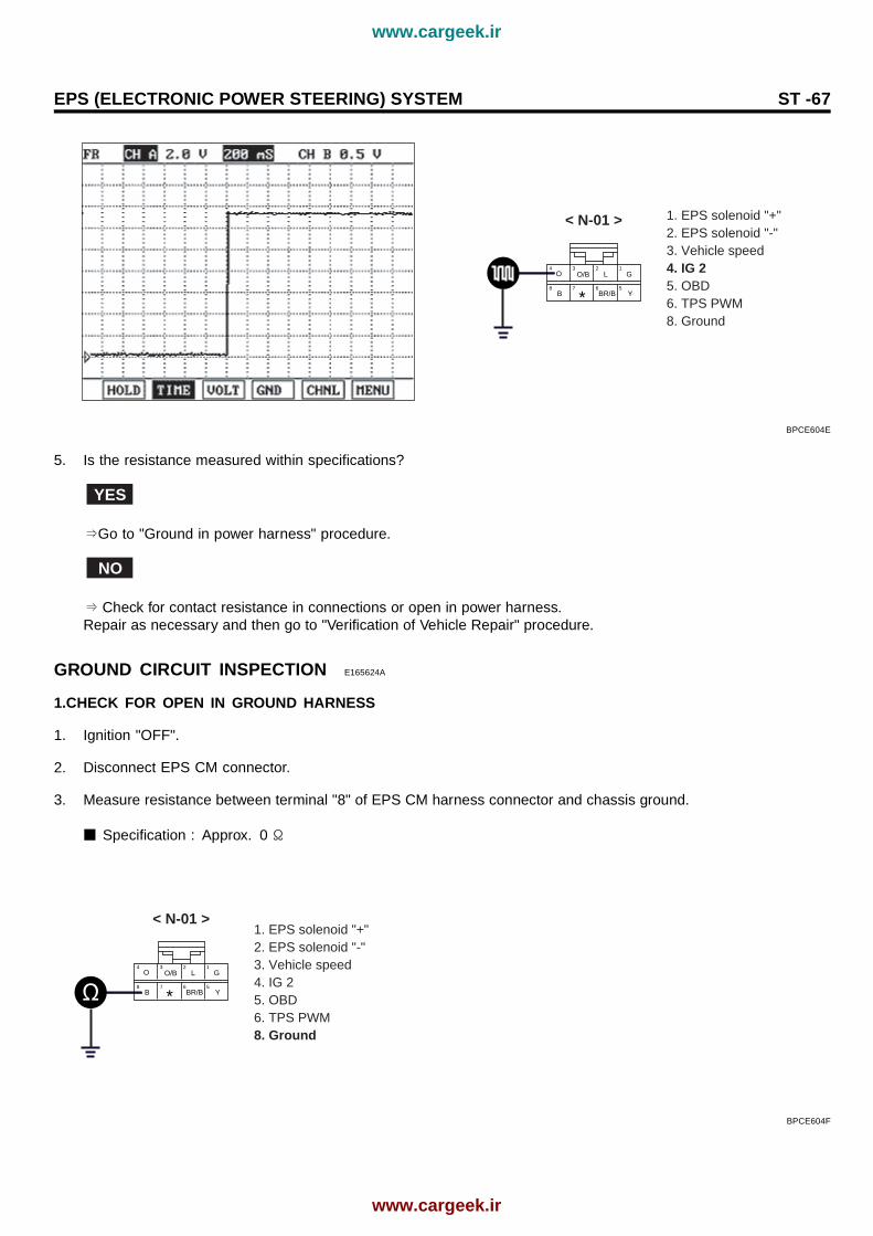
3. Select "SCOPEMETER FUNCTION" on scantool and accelerate engine.
4. Measure output signal between terminal "4"of EPS CM harness connector and chassis ground with switching(A/C,headlight etc.).
Specification : Surge always must not happen when turn IG key ON, OFF with turn the electricity device ON, OFF.
www.cargeek.ir
www.cargeek.ir
EPS (ELECTRONIC POWER STEERING) SYSTEM ST -67
1. EPS solenoid "+"2. EPS solenoid "-"3. Vehicle speed4. IG 25. OBD6. TPS PWM8. Ground
< N-01 >
4 3
8 7 6 5
2 1
B
O/B
BR/B
L G
Y
O
*
BPCE604E
5. Is the resistance measured within specifications?
YES
⇒Go to "Ground in power harness" procedure.
NO
⇒ Check for contact resistance in connections or open in power harness.Repair as necessary and then go to "Verification of Vehicle Repair" procedure.
GROUND CIRCUIT INSPECTION E165624A
1.CHECK FOR OPEN IN GROUND HARNESS
1. Ignition "OFF".
2. Disconnect EPS CM connector.
3. Measure resistance between terminal "8" of EPS CM harness connector and chassis ground.
Specification : Approx. 0 Ω
1. EPS solenoid "+"2. EPS solenoid "-"3. Vehicle speed4. IG 25. OBD6. TPS PWM8. Ground
< N-01 >
4 3
8 7 6 5
2 1
B
O/B
BR/B
L G
Y
O
*
BPCE604F
www.cargeek.ir
www.cargeek.ir
ST -68 STEERING SYSTEM
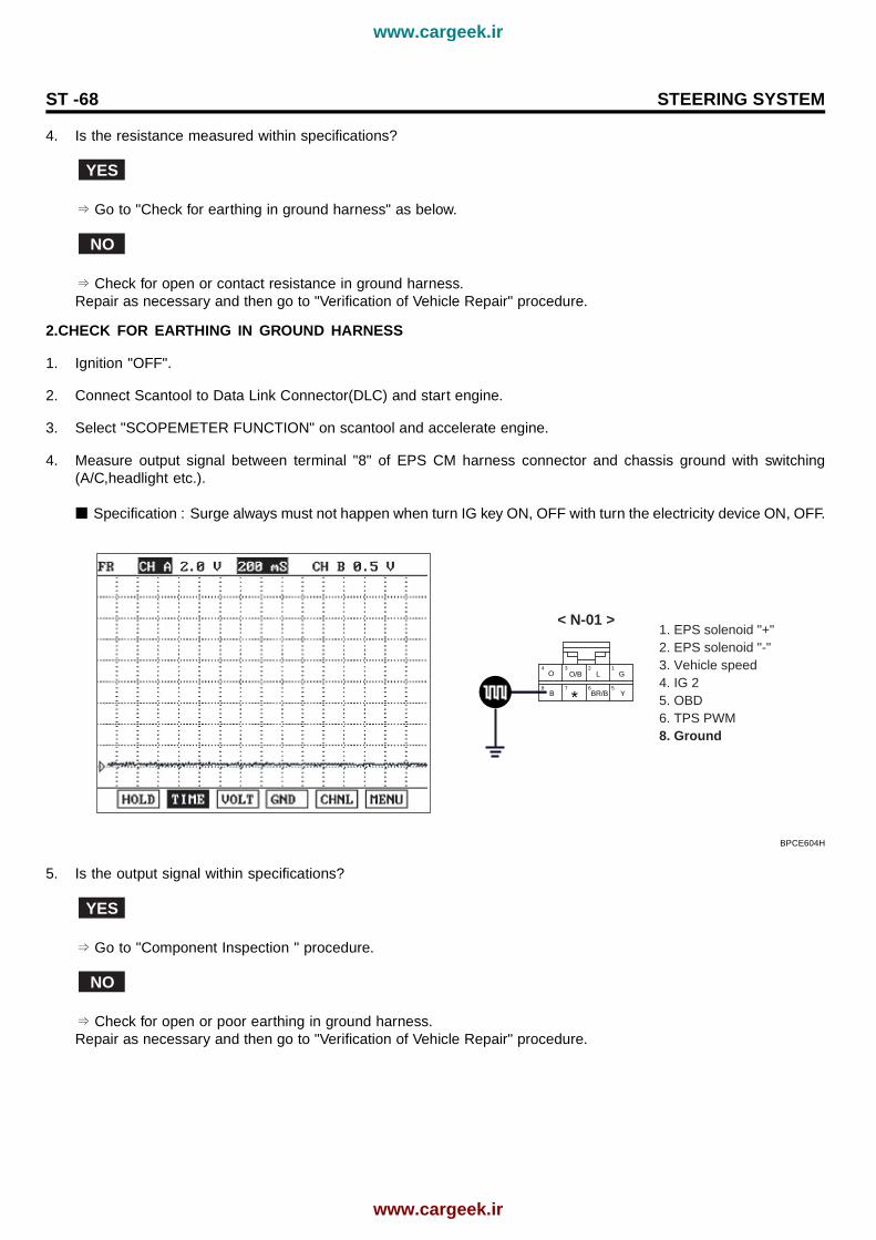
4. Is the resistance measured within specifications?
YES
⇒ Go to "Check for earthing in ground harness" as below.
NO
⇒ Check for open or contact resistance in ground harness.Repair as necessary and then go to "Verification of Vehicle Repair" procedure.
2.CHECK FOR EARTHING IN GROUND HARNESS
1. Ignition "OFF".
2. Connect Scantool to Data Link Connector(DLC) and start engine.
3. Select "SCOPEMETER FUNCTION" on scantool and accelerate engine.
4. Measure output signal between terminal "8" of EPS CM harness connector and chassis ground with switching(A/C,headlight etc.).
Specification : Surge always must not happen when turn IG key ON, OFF with turn the electricity device ON, OFF.
1. EPS solenoid "+"2. EPS solenoid "-"3. Vehicle speed4. IG 25. OBD6. TPS PWM8. Ground
< N-01 >
4 3
8 7 6 5
2 1
B
O/B
BR/B
L G
Y
O
*
BPCE604H
5. Is the output signal within specifications?
YES
⇒ Go to "Component Inspection " procedure.
NO
⇒ Check for open or poor earthing in ground harness.Repair as necessary and then go to "Verification of Vehicle Repair" procedure.
www.cargeek.ir
www.cargeek.ir

EPS (ELECTRONIC POWER STEERING) SYSTEM ST -69
COMPONENT INSPECTION EAF9F5FA
1. Connect scantool and select "Diagnostic Trouble Codes(DTCs)" mode.
2. Clear DTC.
3. Drive the vehicle within DTC Enable conditions in General information.
4. Are any DTCs present ?
YES
⇒ Check EPS CM for damage or sticking by the naked eye. Substitute with a known-good EPS CM and check forproper operation.If the problem is corrected, replace EPS CM and then go to "Verification of vehicle Repair" procedure.
NO
⇒ Substitute with a known-good EPS CM and check for proper operation.If the problem is corrected, replace EPS CM and then go to "Verification of Vehicle Repair" procedure.
www.cargeek.ir
www.cargeek.ir

ST -70 STEERING SYSTEM
DTC C2230 SOLENID
COMPONENT LOCATION E5DDAE5D
Power steeringgear box
EPRF602S
GENERAL DESCRIPTION E8C48A9C
EPS CM controls current amounts to the solenoid valve which adjust driving force of steering wheel, based on vehiclespeed information recieved from the vehicle speed sensor. The EPS solenoid maintains proper steering force by adjustingfluid amounts into the EPS valvebody according to current values.
Solenoid control current Vs Vehicle speed( Vehicle speed increase, solenoid current value is decreased )
BPCE605B
DTC DESCRIPTION EC1B81DD
If an open/short is detected in the solenoid circuit. or current value is under/over, while EPS CM is monitoring solenoid’scurrent, EPS CM sets this trouble and the current value will be controlled "0".
www.cargeek.ir
www.cargeek.ir

EPS (ELECTRONIC POWER STEERING) SYSTEM ST -71
DTC DETECTING CONDITION EE4A56AC
Item Detecting Condition Possible CauseDTC Strategy Current check
Enable Conditions IG key "ON"
Threshold Value Diagnostic Time
Measuer current > 1.28A 1 sec
Solenoid open 1 sec
[target current-measure current]> 0.2A and IG(V)>13V 2 sec
Fail Safe Prohibit solenoid ’s current control ( 0 A )Restoration condition : Power ON reset
- Open/short in power circuitand control circuit
- Contact resistance inconnections.
- Faulty solenoid
SPECIFICATION EBAC1F6B
Solenoid resistance Frequency Duty
5.7~7.7Ω [at 20(68)] 125/333 Hz 5~95%
SIGNAL WAVEFORM ED9EF678
Fig1 Idle Fig2 Vehicle speed increase
Fig 1) Normal signal waveform which is the current control at idle (1A). Fig 2) Signal waveform which is the current decrease by vehicle speed increase.
BPCE605C
MONITOR SCANTOOL DATA EF5A65FC
1. Ignition "OFF" and connect scantool to Data Link Connector(DLC).
2. Ignition "ON" Engine "OFF".
3. Select "DIAGNOSTIC TROUBLE CODES" mode and monitor "Diagnostic Trouble Codes(DTCs)".
www.cargeek.ir
www.cargeek.ir

ST -72 STEERING SYSTEM
Fig1 Diagnostic Trouble Code (abnormal) Sensor current data (abnormal) Fig2
BPCE605D
4. Is parameter within specifications?
YES
⇒ Fault is intermittent and caused either by poor contact in connectors or wiring harness, or it has been repairedand EPS CM memory is not cleared yet. Thoroughly check all connectors (and connections) for looseness, bending,corrosion, contamination, deterioration, and/or damage.Repair or replace as necessary and then go to "Verification of Vehicle Repair" procedure.
NO
⇒ Go to "W/Harness Inspection" procedure.
TERMINAL AND CONNECTOR INSPECTION EB026EB9
1. Many malfunctions in the electrical system are caused by poor harness and terminals. Faults can also be caused byinterference from other electrical systems, and mechanical or chemical damage.
2. Thoroughly check all connectors (and connections) for looseness, bending, corrosion, contamination, deterioration,and/or damage.
3. Has a problem been found?
YES
⇒ Repair as necessary and then go to "Verification of Vehicle Repair" procedure.
NO
⇒ Go to "Power Circuit Inspection" procedure.
www.cargeek.ir
www.cargeek.ir

EPS (ELECTRONIC POWER STEERING) SYSTEM ST -73
POWER CIRCUIT INSPECTION E2A9DBA7
1. Ignition "OFF".
2. Disconnect solenoid connector.
3. Engine "ON".
4. Measure voltage between terminal "1" of solenoid harness connector and chassis ground.
Specification : Approx. B+
1.Solenoid (+)2.Solenoid (-)
v
< N-02 >
1
G2
L
BPCE605E
5. Is the voltage measured within specifications?
YES
⇒ Go to "Control Circuit Inspection" procedure.
NO
⇒ Measure voltage between terminal "1" of EPS CM harness connector and chassis ground in above condition.
Specification : Approx. B+
1. EPS solenoid "+"2. EPS solenoid "-"3. Vehicle speed4. IG 25. OBD6. TPS PWM8. Ground
v
< N-01 >
4 3
8 7 6 5
2 1
B
O/B
BR/B
L G
Y
O
*
BPCE605F
If it is normal, Check for open/short to ground or control harness in power harness. Repair as necessary and thengo to "Verification of Vehicle Repair" procedure.
www.cargeek.ir
www.cargeek.ir

ST -74 STEERING SYSTEM
If it is abnormal, substitute with a known-good EPS CM and check for proper operation. If the problem is corrected,replace EPS CM and then go to "Verification of Vehicle Repair" procedure.
CONTROL CIRCUIT INSPECTION EC16C8C9
1. Ignition "OFF".
2. Disconnect solenoid connector and EPS CM connector.
3. Measure resistance between terminal "2"of solenoid harness connector and terminal "2" of EPS CM harness con-nector.
Specification : Approx. 0 Ω
1.EPS solenoid (+) 2.EPS solenoid (-) 3.Vehicle speed 4.IG 2
1.Solenoid (+)2.Solenoid (-)
< N-01 >
4 3
8 7 6 5
2 1
B
O/B
BR/B
L G
Y
O
*
< N-02 >
1
G2
L
5.OBD6.TPS PWM 7.Space8.Ground
BPCE605G
4. Is the measured resistance within specifications?
YES
⇒ Check for short to ground in control harness. If it is normal, go to "Component Inspection" procedure. If it is abnormal, repair as necessary and then go to "Verification of Vehicle Repair" procedure.
NO
⇒ Check for open/short to ground in control harness.Repair as necessary and then go to "Verification of Vehicle Repair" procedure.
COMPONENT INSPECTION E5D9BAB3
CHECK EPS SOLENOID
1. Ignition "OFF".
2. Disconnect EPS solenoid connector.
3. Measure resistance between terminal "2" and terminal "1" of solenoid harness connector(To sensor side).
Specification : 5.7~7.7Ω [at 20(68)]
www.cargeek.ir
www.cargeek.ir
EPS (ELECTRONIC POWER STEERING) SYSTEM ST -75
1.Solenoid (+)2.Solenoid (-)
< N-02 >
1
G2
L
BPCE605H
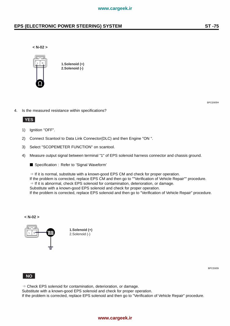
4. Is the measured resistance within specifications?
YES
1) Ignition "OFF".
2) Connect Scantool to Data Link Connector(DLC) and then Engine "ON ".
3) Select "SCOPEMETER FUNCTION" on scantool.
4) Measure output signal between terminal "1" of EPS solenoid harness connector and chassis ground.
Specification : Refer to ’Signal Waveform’
⇒ If it is normal, substitute with a known-good EPS CM and check for proper operation.If the problem is corrected, replace EPS CM and then go to ""Verification of Vehicle Repair"" procedure.⇒ If it is abnormal, check EPS solenoid for contamination, deterioration, or damage.Substitute with a known-good EPS solenoid and check for proper operation.If the problem is corrected, replace EPS solenoid and then go to "Verification of Vehicle Repair" procedure.
1.Solenoid (+)2.Solenoid (-)
< N-02 >
1
G2
L
BPCE605I
NO
⇒ Check EPS solenoid for contamination, deterioration, or damage.Substitute with a known-good EPS solenoid and check for proper operation.If the problem is corrected, replace EPS solenoid and then go to "Verification of Vehicle Repair" procedure.
www.cargeek.ir
www.cargeek.ir