steering, suspension, and driveline basics -...
TRANSCRIPT
Steering, Suspension, and Driveline Basics
(with How Lift Kits Change It) By Mike Harbison
(AKA gojeepin--Jeep Forum, Jeeps Unlimited, 4WD, Tampa Bay Area Jeep Association, and Middle
Peninsula Jeep Assoc, Inc.)
Page 1
UPDATED 30 Jun 12 ~~~~~~~~~~~~~~~~~~~~~~ Added driveline phasing illustration & explanation
INTRODUCTION
Throughout this article I will address many basics of your vehicle’s steering, suspension,
driveline, tires, and wheels. I did not intend this to be a “how to” manual with step by step
instructions. It will simply illustrate the concepts. I’ll start with the lift and explain what it did
to your steering, suspension, and driveline one aspect at a time.
NOTES ABOUT THE ILLUSTRATIONS: 1) most are “spring under” leaf spring suspension,
2) non-pertinent parts are omitted for clarity, 3) many examples are exaggerated for illustration,
and 4) most concepts illustrated also apply to spring over and coil/link suspensions. To cover the
differences, I added a separate coil and link suspensions topic. Ready? OK, let’s get started.
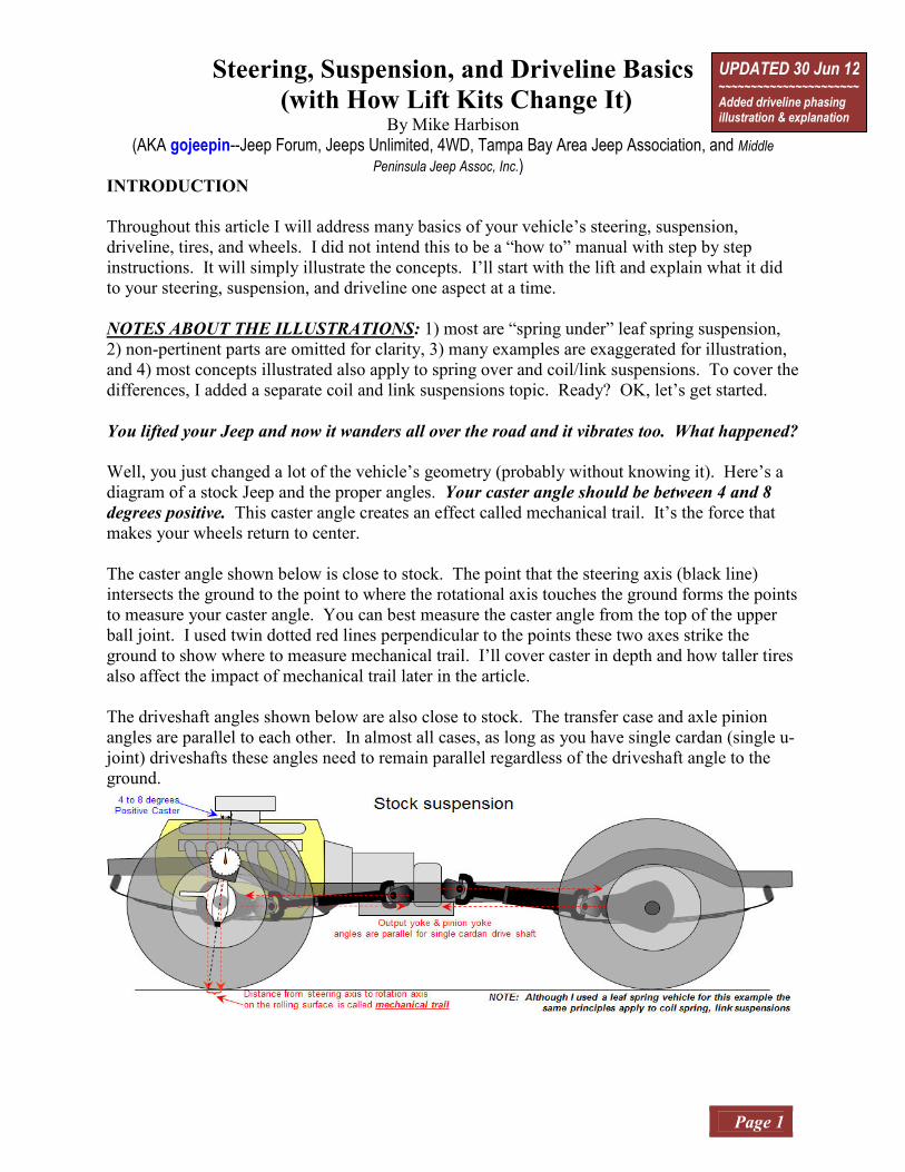
You lifted your Jeep and now it wanders all over the road and it vibrates too. What happened?
Well, you just changed a lot of the vehicle’s geometry (probably without knowing it). Here’s a
diagram of a stock Jeep and the proper angles. Your caster angle should be between 4 and 8
degrees positive. This caster angle creates an effect called mechanical trail. It’s the force that
makes your wheels return to center.
The caster angle shown below is close to stock. The point that the steering axis (black line)
intersects the ground to the point to where the rotational axis touches the ground forms the points
to measure your caster angle. You can best measure the caster angle from the top of the upper
ball joint. I used twin dotted red lines perpendicular to the points these two axes strike the
ground to show where to measure mechanical trail. I’ll cover caster in depth and how taller tires
also affect the impact of mechanical trail later in the article.
The driveshaft angles shown below are also close to stock. The transfer case and axle pinion
angles are parallel to each other. In almost all cases, as long as you have single cardan (single u-
joint) driveshafts these angles need to remain parallel regardless of the driveshaft angle to the
ground.

INTRODUCTION
Page 2
The following diagram shows what happened when you put a lift kit on your Jeep. As noted
above, although I used a leaf spring example, coil and link suspensions will experience most of
the same effects. Your lift not only raised the frame, it increased the distance between the frame
and axles. To absorb the new length of your lift springs, you may need longer shackles to allow
them to flex (flatten). Your springs will pivot at the frame’s spring mount from swinging away
from the frame’s shackle mount (link suspensions perform similarly). First, this will rotate axles
slightly (blue rotation arrows) but enough to cause very noticeable side effects. Your caster
angle will be reduced though possibly not as far as illustrated in the diagram below (reduced to 0
degrees). As for the driveline, the transfer case yokes didn’t change but the pinions did so
they’re no longer parallel.
Now that I’ve illustrated generally what happened, I’ll describe each in more detail.
TABLE OF CONTENTS
TOPIC 1 ........................................................................................................................ CASTER
TOPIC 2 ...................................................................................................................... CAMBER
TOPIC 3 ........................................................................................................ TOE IN/TOE OUT
TOPIC 4 ............................................................ TURNING RADIUS & ACKERMAN ANGLE
TOPIC 5 .............................................................................................................. BUMP STEER
TOPIC 6 ............................................................................................................ LEAF SPRINGS
TOPIC 7 .............................................................................................................. SPRING-OVER
TOPIC 8 .................................................................................................................. DRIVELINE
TOPIC 9 ............................................................................................ WHEEL & TIRE BASICS
TOPIC 10 ................................................................. DEATH WOBBLE--WHEEL BALANCE
TOPIC 11 .................................................................................... COIL & LINK SUSPENSION
CONCLUSION
TOPIC 1: CASTER
Page 3
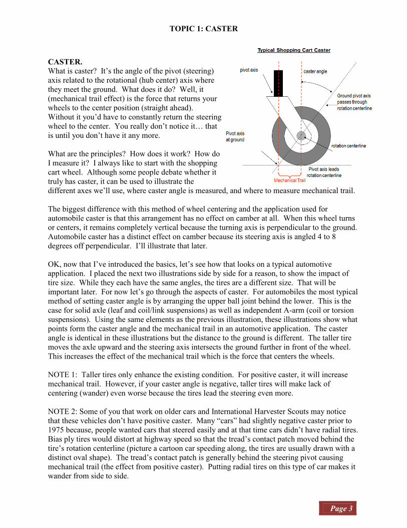
CASTER. What is caster? It’s the angle of the pivot (steering)
axis related to the rotational (hub center) axis where
they meet the ground. What does it do? Well, it
(mechanical trail effect) is the force that returns your
wheels to the center position (straight ahead).
Without it you’d have to constantly return the steering
wheel to the center. You really don’t notice it… that
is until you don’t have it any more.
What are the principles? How does it work? How do
I measure it? I always like to start with the shopping
cart wheel. Although some people debate whether it
truly has caster, it can be used to illustrate the
different axes we’ll use, where caster angle is measured, and where to measure mechanical trail.
The biggest difference with this method of wheel centering and the application used for
automobile caster is that this arrangement has no effect on camber at all. When this wheel turns
or centers, it remains completely vertical because the turning axis is perpendicular to the ground.
Automobile caster has a distinct effect on camber because its steering axis is angled 4 to 8
degrees off perpendicular. I’ll illustrate that later.
OK, now that I’ve introduced the basics, let’s see how that looks on a typical automotive
application. I placed the next two illustrations side by side for a reason, to show the impact of
tire size. While they each have the same angles, the tires are a different size. That will be
important later. For now let’s go through the aspects of caster. For automobiles the most typical
method of setting caster angle is by arranging the upper ball joint behind the lower. This is the
case for solid axle (leaf and coil/link suspensions) as well as independent A-arm (coil or torsion
suspensions). Using the same elements as the previous illustration, these illustrations show what
points form the caster angle and the mechanical trail in an automotive application. The caster
angle is identical in these illustrations but the distance to the ground is different. The taller tire
moves the axle upward and the steering axis intersects the ground further in front of the wheel.
This increases the effect of the mechanical trail which is the force that centers the wheels.
NOTE 1: Taller tires only enhance the existing condition. For positive caster, it will increase
mechanical trail. However, if your caster angle is negative, taller tires will make lack of
centering (wander) even worse because the tires lead the steering even more.
NOTE 2: Some of you that work on older cars and International Harvester Scouts may notice
that these vehicles don’t have positive caster. Many “cars” had slightly negative caster prior to
1975 because, people wanted cars that steered easily and at that time cars didn’t have radial tires.
Bias ply tires would distort at highway speed so that the tread’s contact patch moved behind the
tire’s rotation centerline (picture a cartoon car speeding along, the tires are usually drawn with a
distinct oval shape). The tread’s contact patch is generally behind the steering pivot causing
mechanical trail (the effect from positive caster). Putting radial tires on this type of car makes it
wander from side to side.

TOPIC 1: CASTER
Page 4
OK… so what did your lift (or longer shackles) do to your caster? Well, as you can see at the
right, the suspension only pivots on one end, the axle tips forward. A coil/link suspension would
change the same way unless you had adjustable link arms (and made an adjustment).
The upper ball joint has moved forward to the point it doesn’t trail the lower by much.
Such a small change has altered your steering geometry considerably. It reduced your caster
angle and mechanical trail force, while reducing your camber change during turns.
This is probably the most common problem encountered after a suspension lift. There are
several ways to correct it.
1. You can rotate the “Cs” that hold your
ball joints.
2. You can cut off and remount spring
perches (or mounts)
3. You can use a offset ball joint or offset
mount.
4. On some axles you can grind the perch
enough to change the angle.
Ok… let’s say you just bought a used CJ
(or YJ) that has a completely stock
suspension but the Jeep wanders all over
the road. Yes, the suspension is old and
many components could be at fault for
steering problems, but as covered earlier,
wander is caused by lack of positive
caster.
TOPIC 1: CASTER
Page 5
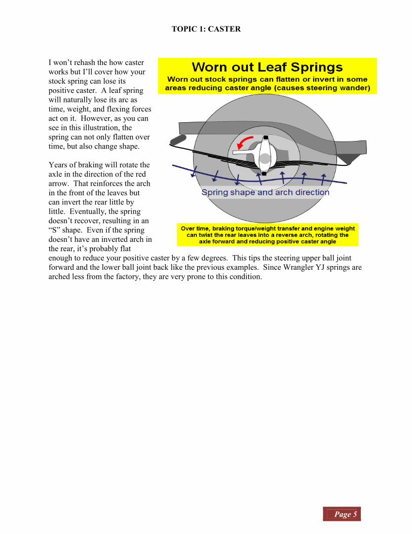
I won’t rehash the how caster
works but I’ll cover how your
stock spring can lose its
positive caster. A leaf spring
will naturally lose its arc as
time, weight, and flexing forces
act on it. However, as you can
see in this illustration, the
spring can not only flatten over
time, but also change shape.
Years of braking will rotate the
axle in the direction of the red
arrow. That reinforces the arch
in the front of the leaves but
can invert the rear little by
little. Eventually, the spring
doesn’t recover, resulting in an
“S” shape. Even if the spring
doesn’t have an inverted arch in
the rear, it’s probably flat
enough to reduce your positive caster by a few degrees. This tips the steering upper ball joint
forward and the lower ball joint back like the previous examples. Since Wrangler YJ springs are
arched less from the factory, they are very prone to this condition.

TOPIC 2: CAMBER
Page 6
CAMBER.
So you’ve raised your vehicle but your wheels are slanted and tires are wearing. Improper
camber takes valuable rubber off the road by riding on the edges of the tire tread. Some positive
or negative camber is normal and is used to control turning stability and responsiveness. Too
much camber will not only wear tires prematurely but can also make steering difficult or
unresponsive.
What is Camber? Camber is measured in degrees,
either positive or negative. It affects the “feel” of
your steering, either heavy or responsive. For us,
camber changes are most often caused by worn parts.
With proper camber adjustment and alignment
correction, the car will be more responsive and
handle better wet or dry. Solid front axle vehicles
don’t see this change with a lift because the solid
front axle maintains the inboard & outboard position
of the ball joints. Those with independent front
suspension will since the lift probably moved the
upper ball joint’s position relative to the lower.
If the wheel leans away from the car, it has positive camber if it leans in towards the chassis; it
has negative camber (see next page). The cornering force of your tires is highly dependent on its
angle relative to the road surface, so wheel camber has a major effect on the handling. Typically,
tires develop maximum cornering force at around .5 degrees negative which is a small negative
camber angle. This is caused by the additional lateral force generated by deformation as tread’s
contact area rubber pulls through the tire/road surface.
For many years camber was set from zero to slightly positive to offset vehicle loading and to
make steering easier for non-power steering vehicles, however the current trend is to slightly
negative settings to increase vehicle stability and improve handling. All solid axle suspensions
change and most independent suspensions will vary the camber angle as the wheel moves up and
down relative to the chassis.
Positive Camber When the bottom of the tire is more inwards and
the top is out, that is referred to as positive camber.
Positive Camber makes the steering “lighter” to the
touch and was very helpful when vehicles didn’t
have power steering. The penalty for too much
positive camber is vehicle under-steer (turning less
than your steering input) and wear on the outside
of your tires. Today it’s generally the result of a
bad alignment or a worn out ball joint. A camber
kit isn’t usually required because replacing the
worn part and realignment generally corrects the
problem.

TOPIC 2: CAMBER
Page 7
Negative Camber Negative camber is when the top of the tire is
more towards the center of the vehicle and the
bottom is outwards. Your suspension should
have near 0 degrees camber. Negative camber
increases steering force but excessive negative
camber will wear the inside of your tires at a
rapid rate and lead to over-steer. Over-steer in a
short wheelbase vehicle will often result in a
spinout since any turns could be abrupt.
I mentioned earlier in the Caster topic that your
Camber changes during turns. This is because
your steering pivot axis is not vertical to the
ground.
If your steering’s pivot angle was perpendicular to the ground, your tires would remain vertical
as they turned. As you can see in the illustrations below, because of your Caster angle that is not
the case. Your tires lean as they turn. The sharper you turn, the more the tires will lean. In
addition, the more caster angle (pivot tipped back) you have, the more camber change it causes
(tires lean more).
This allows your steering camber to be set to nearly zero degrees for straight line travel while
applying the appropriate camber when it’s needed for a turn.
TOPIC 3: TOE IN/TOE OUT
Page 8
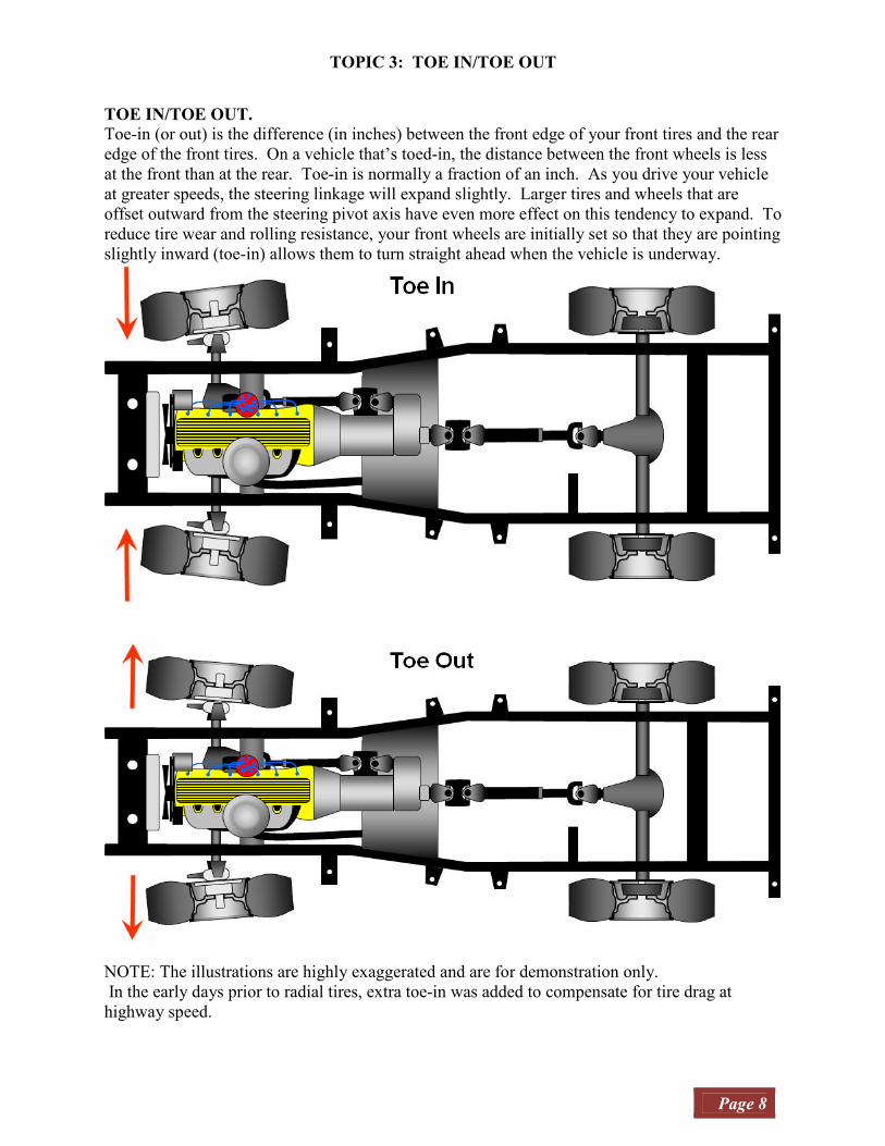
TOE IN/TOE OUT.
Toe-in (or out) is the difference (in inches) between the front edge of your front tires and the rear
edge of the front tires. On a vehicle that’s toed-in, the distance between the front wheels is less
at the front than at the rear. Toe-in is normally a fraction of an inch. As you drive your vehicle
at greater speeds, the steering linkage will expand slightly. Larger tires and wheels that are
offset outward from the steering pivot axis have even more effect on this tendency to expand. To
reduce tire wear and rolling resistance, your front wheels are initially set so that they are pointing
slightly inward (toe-in) allows them to turn straight ahead when the vehicle is underway.
NOTE: The illustrations are highly exaggerated and are for demonstration only.
In the early days prior to radial tires, extra toe-in was added to compensate for tire drag at
highway speed.

TOPIC 4: TURNING RADIUS & ACKERMAN ANGLE
Page 9
The subject of turning radius comes up from time to time,
usually associated with a suspension lift and the installation of a
drop pitman arm. While a drop Pitman arm is often required to
bring the drag link back into the proper alignment, the problem is
caused by a Pitman arm that's shorter than needed. The drop
Pitman arm may appear to be the same length but it must be
measured from the axis-center of each hole (not a straight line
from each hole) as shown in the illustration on the right.
The illustration below shows an example of how much of a
steering output reduction is provided because of this difference.
Since the Pitman arm swings in a smaller arc, the steering range
is narrower.
In the next illustrations you can see
that the smaller arc of the shorter
Pitman arm doesn't turn the wheels
quite as far when the steering is turned
to full extension in either direction.
Although the difference doesn't seem
like much, it makes a big difference in
the distance required to turn your
vehicle around.
NOTE: The differences here are
notional for illustration only. Do not
use them as a guide to set your
steering.

TOPIC 4: TURNING RADIUS & ACKERMAN ANGLE
Page 10
The Ackerman Angle is one of those topics that appears on the technical forums once in a while
when someone has been reading about steering concepts. While they gain new insight from this
reading, they often will find topics that don't apply to their situation.
I only bring this up in
case you read about it
somewhere or hear
about it at an
alignment shop.
It's not normally
something a do-it-
yourselfer should ever
try because this is
something that's
designed in the vehicle
and Jeep CJs and
Wranglers were not
designed this way.
As you can see in the
illustration, the inside
wheel turns sharper
than the outside wheel
to make the turn
smooth because the
shorter inside radius
requires a sharper turn
to travel the
circumference path
without scrubbing.
Note the position of
the steering arms and
tie rod (or rack and
pinion in some
vehicles). It is on the
rear of the steering
knuckle. It's doubtful
you could achieve this
angle from the front
without contacting the
wheel.
The second illustration shows the easiest way to calculate the position of the steering arms. They
would ideally be inline with the line drawn to the center of the rear axle.
TOPIC 4: TURNING RADIUS & ACKERMAN ANGLE
Page 11
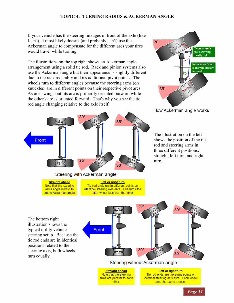
If your vehicle has the steering linkages in front of the axle (like
Jeeps), it most likely doesn't (and probably can't) use the
Ackerman angle to compensate for the different arcs your tires
would travel while turning.
The illustrations on the top right shows an Ackerman angle
arrangement using a solid tie rod. Rack and pinion systems also
use the Ackerman angle but their appearance is slightly different
due to the rack assembly and it's additional pivot points. The
wheels turn to different angles because the steering arms (on
knuckles) are in different points on their respective pivot arcs.
As one swings out, its arc is primarily oriented outward while
the other's arc is oriented forward. That's why you see the tie
rod angle changing relative to the axle itself.
The illustration on the left
shows the position of the tie
rod and steering arms in
three different positions:
straight, left turn, and right
turn.
The bottom right
illustration shows the
typical utility vehicle
steering setup. Because the
tie rod ends are in identical
positions related to the
steering axis, both wheels
turn equally

TOPIC 5: BUMP-STEER
Page 12
BUMP-STEER.
This steering malady is experience by many who
put a suspension lift on their vehicle. I often will
leave well enough alone myself… meaning I know
where I could have a problem but wait to see if I
really do have a problem. I didn’t correct my
steering geometry at first, hoping that it would be
fine. I was wrong. I had a very bad case of bump-
steer.
Here’s what a typical alignment of steering
components look like. They are nearly parallel to
each other. The swing radius (red arrow) on the
drag link moves in a gentle arc nearly straight up
and down. When you hit a bump with the
passenger tire, the steering components will remain
relatively neutral and you’ll not get steering
feedback.
However, your steering geometry changes when
you put on a suspension lift. The drag link is now
at a much steeper angle to the tie rod. The wheel’s
pivot radius is now going to advance as the
passenger wheel goes up and retreat as the
passenger wheel goes down. The further the
wheel travels (up or down), the more steering
effect you’ll have. Because this travel is often
associated with hitting bumps, the effect is sudden
and sometimes severe. It’s enough to make you
lose control of your vehicle.
A sight sometimes seen on highly lifted vehicles is
the bent or angled drag link. The drag link may
visually appear to be near stock configuration but
as you can see in the illustration; these bends don’t
change the angles. You will still have bump-steer.
There is really only one reason to bend or angle
the drag link... so it will clear (avoid striking)
other components. For instance, sometimes a
spring over conversion puts the direct path of the
drag link to steering knuckle through the leaf
spring. Since you can’t go through it you’ll need
to go around.
TOPIC 5: BUMP-STEER
Page 13
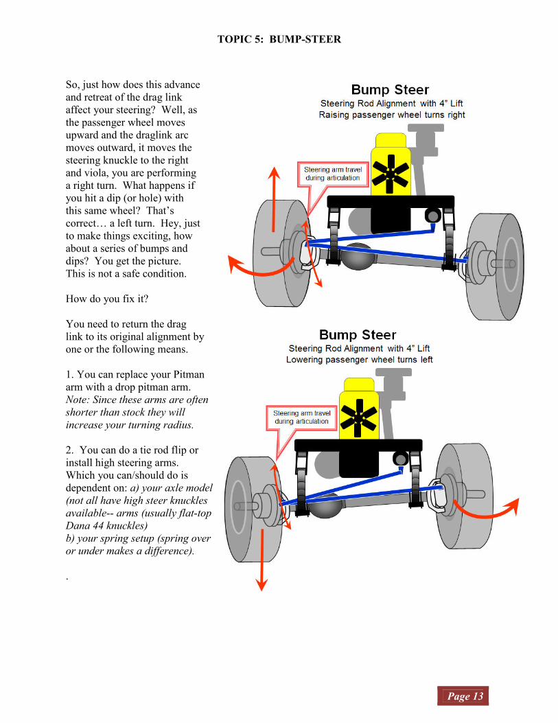
So, just how does this advance
and retreat of the drag link
affect your steering? Well, as
the passenger wheel moves
upward and the draglink arc
moves outward, it moves the
steering knuckle to the right
and viola, you are performing
a right turn. What happens if
you hit a dip (or hole) with
this same wheel? That’s
correct… a left turn. Hey, just
to make things exciting, how
about a series of bumps and
dips? You get the picture.
This is not a safe condition.
How do you fix it?
You need to return the drag
link to its original alignment by
one or the following means.
1. You can replace your Pitman
arm with a drop pitman arm.
Note: Since these arms are often
shorter than stock they will
increase your turning radius.
2. You can do a tie rod flip or
install high steering arms.
Which you can/should do is
dependent on: a) your axle model
(not all have high steer knuckles
available-- arms (usually flat-top
Dana 44 knuckles)
b) your spring setup (spring over
or under makes a difference).
.

TOPIC 6: LEAF SPRINGS
Page 14
Let’s start with how
the leaf springs work.
The longest leaf
attaches the spring
pack assembly.
While simple, it's also
versatile. Each leaf
can have a different
rate, making load and
comfort very tunable.
Most everyone knows
that they suspend the
vehicle vertically but
there are two other aspects. These three aspects of the suspension affect ride quality, steering,
and driveline.
The first illustration in this section shows the underside view of a Jeep CJ7. I’ve colored the
suspension and some steering components blue.
As you can see, I listed the following primary functions:
1) suspend the vehicle,
2) position the axle fore & aft,
3) maintain the axle side-to-side position. Later I’ll explain how this can effect steering
(a secondary function).
You must keep your suspension bushings in good shape and not over-tighten them to perform
these tasks properly. The suspension mounting points are marked with an orange box. These
points position the axle both fore/aft and side-to-side however, unlike a link-arm suspension, the
axle’s front to back position changes more as the suspension articulates.
Now, knowing which way your suspension moves during compression and droop is important
for axle placement and tire clearance. Depending on your suspension setup (e.g. shackle
reversal), you could encounter tire/body contact with your axle positioned in the same place as
someone else. The next two illustrations show how the axle travels through its three positions, at
rest, compressed, and extended. The first illustration is stock configuration.

TOPIC 6: LEAF SPRINGS
Page 15
A shackle reversal kit has been installed in this illustration. The setup changes the front spring’s
rear mount considerably since the shackle stands the spring between 2 and 5 inches further from
the frame. In addition, the front mount may also extend the spring eye further from the frame
depending on manufacturer. These changes will most likely change your Caster (one way or the
other).
This motion becomes important for tire/body clearance, handling, and driveline. On the stock
setup, the frame moves backward relative to the axle when you compress the suspension. So, if
you’re trying to climb a rock, the front wheel will work against your momentum slightly, but that
may be enough to keep you from climbing the obstacle. Your Jeep will naturally be somewhat
neutral during hard braking. Sure, the weight is moving forward and that compresses the spring,
but the brakes are countering the wheels’ forward rotation that applies torque to the axle that
tends to keep it from compressing. The final consideration is the driveshaft. As the spring
compresses, the axle move both up and forward. The makes the pinion move up (closer) but
forward (further). It’s possible that you won’t need much range in your driveshaft’s slip shaft.
A shackle reversal kit changes how your suspension behaves considerably. Some kits even
include a lift that changes steering geometry. I’ll leave it up to you whether you think it’s for the
better or worse. Now, axle positioning is important, if you leave the front axle in the stock
position when you install a shackle reversal kit, you could easily impact the fender with the tire
(depending on tire size and fender shape).

TOPIC 6: LEAF SPRINGS
Page 16
On the reverse setup, the frame moves forward relative to the axle when you compress the
suspension. So, if you’re trying to climb a rock, the front wheel will work with your momentum
and that may be enough to get you over the obstacle. Your Jeep tend to nose dive during hard
braking. In this case, two things cause the problem. First, momentum transfer weight to the
front, compress the spring, and swing the shackles rearward. In this case, the brakes will rotate
the axle “nose down” as they stop the wheel rotation, further swinging the shackles back.
Driveshaft measurement and placement is critical. This time, as the spring compresses, the axle
moves both up and rearward. The makes the pinion move up AND rearward. Likewise, it
moves down and forward when the spring droops. Your driveshaft will move a lot, so make sure
your driveshaft’s slip shaft has enough length.
This leads me to the subject of shackles. Let’s talk about how they affect steering. Sometimes
wander, shimmy, and wobble are not the fault of the steering. Sometimes a poorly maintained
suspension will cause it. Your bushings are what allow suspension flexibility but they also
maintain control. They must remain pliable but firm. Old, hardened, worn bushing will not
work properly for either suspension or steering. The next illustration shows three conditions
involving your shackles.
The illustrations on the next page show some conditions that develop over time with leaf springs
and shackles. Stock shackles have a tendency to lean as they get older because the only things
that keep them operating as one unit are the bolts and bushings. If the bushings get stiff and
brittle, they allow the shackle to start wearing itself apart. For that reason you should maintain
your shackle bushings periodically.
If your shackles lean to one side or the other when the suspension is at rest you probably have
one of the problems illustrated above. Sometimes it results from wear and sometimes from
impact.
TOPIC 6: LEAF SPRINGS
Page 17
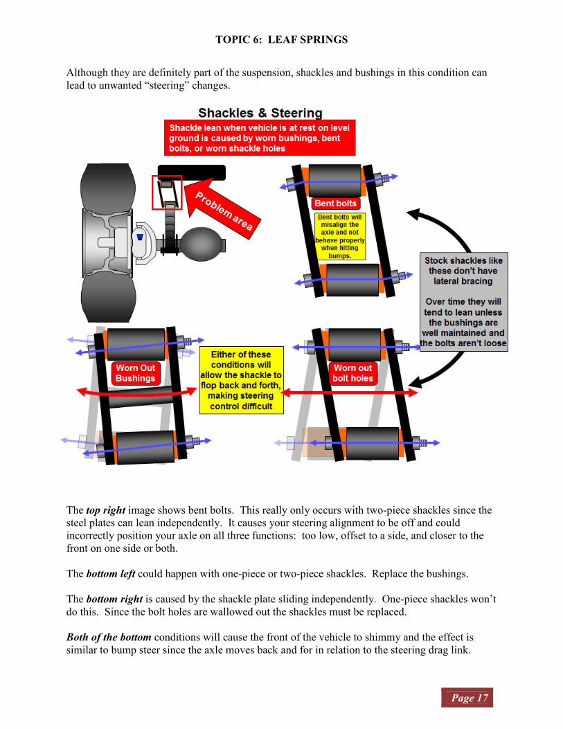
Although they are definitely part of the suspension, shackles and bushings in this condition can
lead to unwanted “steering” changes.
The top right image shows bent bolts. This really only occurs with two-piece shackles since the
steel plates can lean independently. It causes your steering alignment to be off and could
incorrectly position your axle on all three functions: too low, offset to a side, and closer to the
front on one side or both.
The bottom left could happen with one-piece or two-piece shackles. Replace the bushings.
The bottom right is caused by the shackle plate sliding independently. One-piece shackles won’t
do this. Since the bolt holes are wallowed out the shackles must be replaced.
Both of the bottom conditions will cause the front of the vehicle to shimmy and the effect is
similar to bump steer since the axle moves back and for in relation to the steering drag link.
TOPIC 6: LEAF SPRINGS
Page 18
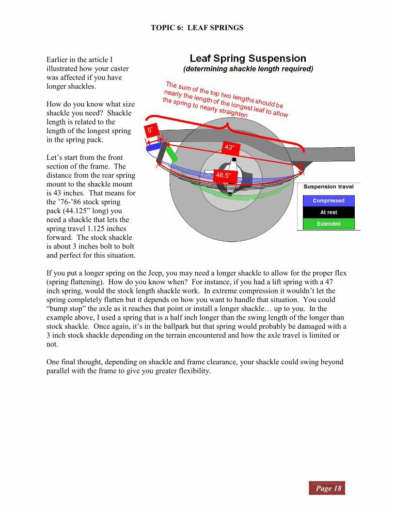
Earlier in the article I
illustrated how your caster
was affected if you have
longer shackles.
How do you know what size
shackle you need? Shackle
length is related to the
length of the longest spring
in the spring pack.
Let’s start from the front
section of the frame. The
distance from the rear spring
mount to the shackle mount
is 43 inches. That means for
the ’76-’86 stock spring
pack (44.125” long) you
need a shackle that lets the
spring travel 1.125 inches
forward. The stock shackle
is about 3 inches bolt to bolt
and perfect for this situation.
If you put a longer spring on the Jeep, you may need a longer shackle to allow for the proper flex
(spring flattening). How do you know when? For instance, if you had a lift spring with a 47
inch spring, would the stock length shackle work. In extreme compression it wouldn’t let the
spring completely flatten but it depends on how you want to handle that situation. You could
“bump stop” the axle as it reaches that point or install a longer shackle… up to you. In the
example above, I used a spring that is a half inch longer than the swing length of the longer than
stock shackle. Once again, it’s in the ballpark but that spring would probably be damaged with a
3 inch stock shackle depending on the terrain encountered and how the axle travel is limited or
not.
One final thought, depending on shackle and frame clearance, your shackle could swing beyond
parallel with the frame to give you greater flexibility.
TOPIC 7: SPRING-OVER SUSPENSION
Page 19
One topic that comes up a lot is spring-over suspensions. It may seem that it’s one of the
cheapest ways to lift a vehicle. You don’t have to buy a suspension lift kit, right?
It’s more than just relocating your spring perches to the top of the axle, flipping the U-bolts, and
tightening the spring plates. You will face all the issues that a spring-under lift will encounter
plus the main problem of axle-wrap. You see, springs are designed to withstand certain stresses
under certain conditions: 1) specific tire size range and 2) a spring relationship to the axle and
ultimately the ground.
Why is axle-wrap a problem for a spring over but not spring under? Well, that’s not always
the case. There are many suspensions that are designed for spring-over operation. For instance,
most pickup trucks use spring-over suspension for the rear axle. Unlike coil springs, each leaf
can add to the cumulative spring rate versus a constant rate from a coil. This allows for both a
smoother ride while unloaded and greater capacity when loaded. The key aspect of this
suspension is that it was built for load capacity and not flexibility. The leaves were designed
from the start to handle the torque from the spring position over the axle. These springs are
designed to withstand the torque from the greater distance to the ground.
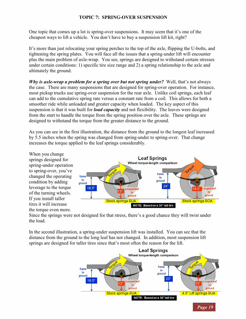
As you can see in the first illustration, the distance from the ground to the longest leaf increased
by 5.5 inches when the spring was changed from spring-under to spring-over. That change
increases the torque applied to the leaf springs considerably.
When you change
springs designed for
spring-under operation
to spring-over, you’ve
changed the operating
condition by adding
leverage to the torque
of the turning wheels.
If you install taller
tires it will increase
the torque even more.
Since the springs were not designed for that stress, there’s a good chance they will twist under
the load.
In the second illustration, a spring-under suspension lift was installed. You can see that the
distance from the ground to the long leaf has not changed. In addition, most suspension lift
springs are designed for taller tires since that’s most often the reason for the lift.
TOPIC 7: SPRING-OVER SUSPENSION
Page 20
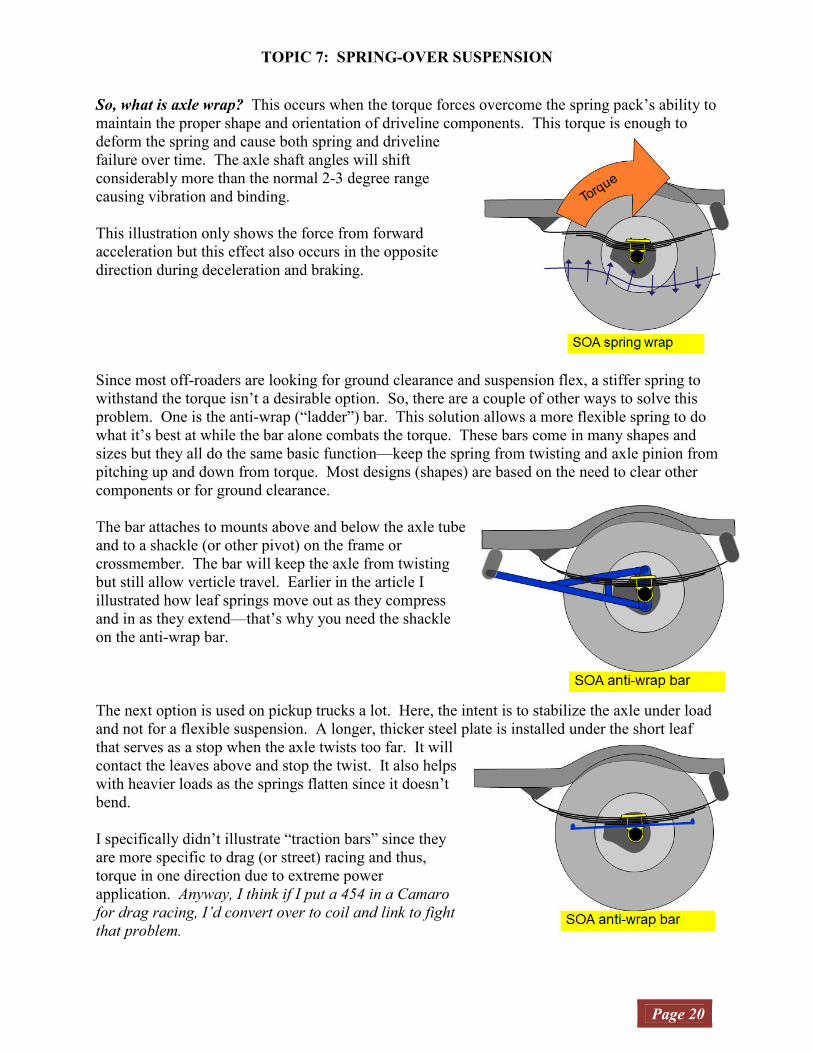
So, what is axle wrap? This occurs when the torque forces overcome the spring pack’s ability to
maintain the proper shape and orientation of driveline components. This torque is enough to
deform the spring and cause both spring and driveline
failure over time. The axle shaft angles will shift
considerably more than the normal 2-3 degree range
causing vibration and binding.
This illustration only shows the force from forward
acceleration but this effect also occurs in the opposite
direction during deceleration and braking.
Since most off-roaders are looking for ground clearance and suspension flex, a stiffer spring to
withstand the torque isn’t a desirable option. So, there are a couple of other ways to solve this
problem. One is the anti-wrap (“ladder”) bar. This solution allows a more flexible spring to do
what it’s best at while the bar alone combats the torque. These bars come in many shapes and
sizes but they all do the same basic function—keep the spring from twisting and axle pinion from
pitching up and down from torque. Most designs (shapes) are based on the need to clear other
components or for ground clearance.
The bar attaches to mounts above and below the axle tube
and to a shackle (or other pivot) on the frame or
crossmember. The bar will keep the axle from twisting
but still allow verticle travel. Earlier in the article I
illustrated how leaf springs move out as they compress
and in as they extend—that’s why you need the shackle
on the anti-wrap bar.
The next option is used on pickup trucks a lot. Here, the intent is to stabilize the axle under load
and not for a flexible suspension. A longer, thicker steel plate is installed under the short leaf
that serves as a stop when the axle twists too far. It will
contact the leaves above and stop the twist. It also helps
with heavier loads as the springs flatten since it doesn’t
bend.
I specifically didn’t illustrate “traction bars” since they
are more specific to drag (or street) racing and thus,
torque in one direction due to extreme power
application. Anyway, I think if I put a 454 in a Camaro
for drag racing, I’d convert over to coil and link to fight
that problem.
TOPIC 8: DRIVELINE
Page 21
DRIVELINE.
Driveline angles are probably the least understood by most shade tree mechanics. From the
factory, your driveline didn’t have much of an angle to adjust to and your u-joints were primarily
to allow axle movement without binding.
The universal joints (u-joints hereafter) allow your driveshaft to operate smoothly at various
angles. However, it must be properly set to avoid oscillation (vibration).
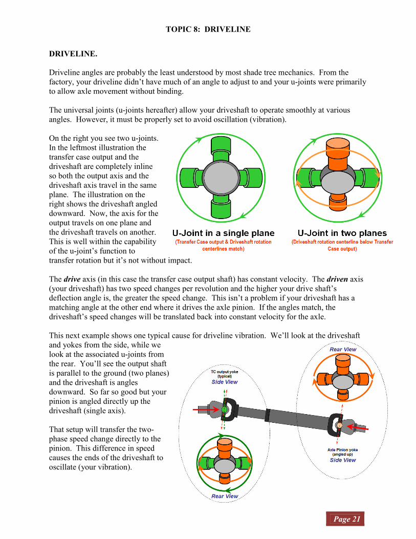
On the right you see two u-joints.
In the leftmost illustration the
transfer case output and the
driveshaft are completely inline
so both the output axis and the
driveshaft axis travel in the same
plane. The illustration on the
right shows the driveshaft angled
downward. Now, the axis for the
output travels on one plane and
the driveshaft travels on another.
This is well within the capability
of the u-joint’s function to
transfer rotation but it’s not without impact.
The drive axis (in this case the transfer case output shaft) has constant velocity. The driven axis
(your driveshaft) has two speed changes per revolution and the higher your drive shaft’s
deflection angle is, the greater the speed change. This isn’t a problem if your driveshaft has a
matching angle at the other end where it drives the axle pinion. If the angles match, the
driveshaft’s speed changes will be translated back into constant velocity for the axle.
This next example shows one typical cause for driveline vibration. We’ll look at the driveshaft
and yokes from the side, while we
look at the associated u-joints from
the rear. You’ll see the output shaft
is parallel to the ground (two planes)
and the driveshaft is angles
downward. So far so good but your
pinion is angled directly up the
driveshaft (single axis).
That setup will transfer the two-
phase speed change directly to the
pinion. This difference in speed
causes the ends of the driveshaft to
oscillate (your vibration).

TOPIC 8: DRIVELINE
Page 22
The illustration below shows two complete rotations of the transfer case (or transmission if two-
wheel drive) using the same color references on the previous page. Please note that in this
illustration I use the term “input shaft” for the transfer case output yoke and “output shaft”
for the driveshaft.
So, continuing the previous discussion, the transfer case yoke drives the green poles and the
orange poles drive the driveshaft. At the beginning of the rotation, the transfer case yoke poles
are in the vertical position. This is the point of greatest speed difference between the input and
output. The speed difference increased rapidly to this point where it is 2:1 (using the 60° shaft
deflection example). While most other deflection angles are not this dramatic, it occurs for all
but 0º deflection. While the faster than input deviations are greater than the slower than input,
the durations are shorter.
The slower than input speed durations are longer than the faster than input speed durations. I
included an input shaft position rotation degrees scale to illustrate. Once again, using the 60°
deflection angle example, the driveshaft rotates 60° faster, 120° slower, 60° faster, and 120°
slower.
TOPIC 8: DRIVELINE
Page 23
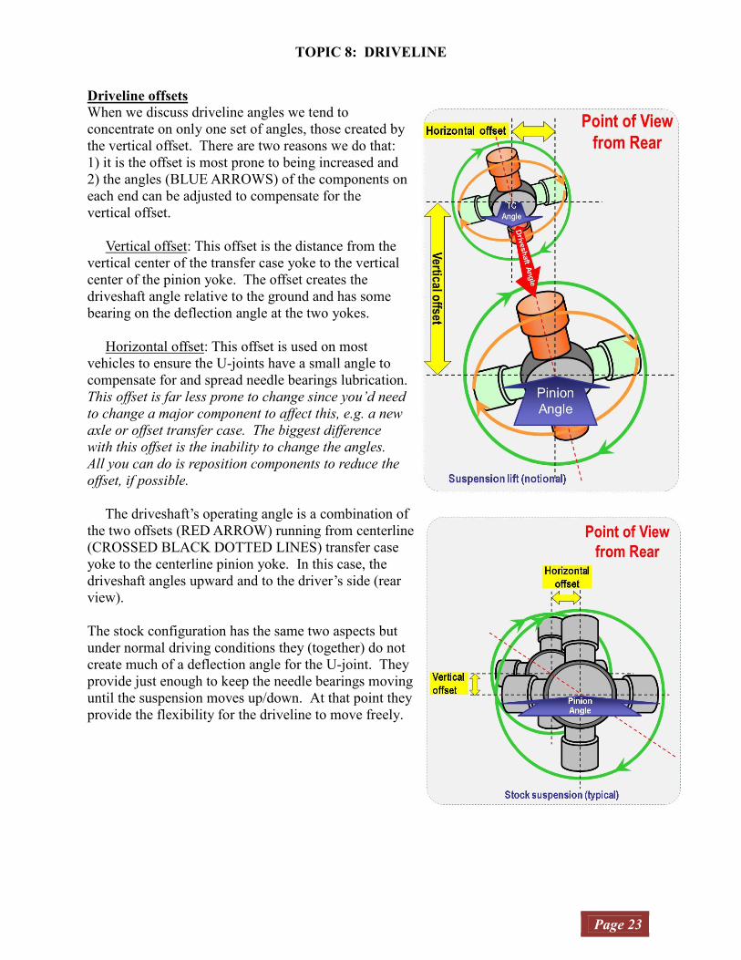
Driveline offsets
When we discuss driveline angles we tend to
concentrate on only one set of angles, those created by
the vertical offset. There are two reasons we do that:
1) it is the offset is most prone to being increased and
2) the angles (BLUE ARROWS) of the components on
each end can be adjusted to compensate for the
vertical offset.
Vertical offset: This offset is the distance from the
vertical center of the transfer case yoke to the vertical
center of the pinion yoke. The offset creates the
driveshaft angle relative to the ground and has some
bearing on the deflection angle at the two yokes.
Horizontal offset: This offset is used on most
vehicles to ensure the U-joints have a small angle to
compensate for and spread needle bearings lubrication.
This offset is far less prone to change since you’d need
to change a major component to affect this, e.g. a new
axle or offset transfer case. The biggest difference
with this offset is the inability to change the angles.
All you can do is reposition components to reduce the
offset, if possible.
The driveshaft’s operating angle is a combination of
the two offsets (RED ARROW) running from centerline
(CROSSED BLACK DOTTED LINES) transfer case
yoke to the centerline pinion yoke. In this case, the
driveshaft angles upward and to the driver’s side (rear
view).
The stock configuration has the same two aspects but
under normal driving conditions they (together) do not
create much of a deflection angle for the U-joint. They
provide just enough to keep the needle bearings moving
until the suspension moves up/down. At that point they
provide the flexibility for the driveline to move freely.

TOPIC 8: DRIVELINE
Page 24
So, what can you do about it? Well, there are a few things.
If you’re going to keep a
single cardan driveshaft you
need to make your angles
match.
Your first, option is to lower
the transfer case output to
match the pinion.
You can buy or make a kit to
lower the transfer case. This
not only reduces the
driveshaft angle at the u-joint
but also changes the output
shaft angle. When you
install a kit, the engine,
transmission, and transfer
case tip back and down.
Make sure your fan still
clears the radiator and no part of the engine strikes the firewall.
The illustration below shows the corrected rear driveline angles. The front driveshaft is now in
an unusual arrangement with the output yoke tipped upward.
Your second option is to shim or relocate the axle perches to lower the pinion to match the
transfer case output yoke. At this point many people opt for a double cardan driveshaft.
Your third option is a double cardan driveshaft. In the illustration on the previous page, I stated
that the angles must be parallel… well; the truth is that they just need to match. The next
illustration shows both yokes approaching from the same side.

TOPIC 8: DRIVELINE
Page 25
What if this driveshaft were cut down to form a single assembly? This is how a double cardan
joint works. The joint assembly does the speed differentiation… constant velocity in and
constant velocity out. The speed phase changes are handled by the two u-joints in the
assembly. A cutaway of the double cardan module is illustrated on the next page.
The illustration below shows the driveline in the proper position for double cardan driveshafts.
In this case you want to keep your output shaft in the stock position and raise the axle pinion to 2
degrees below the driveshaft centerline. The driveline is now fixed and assuming your
driveshafts are balanced, vibration free.

TOPIC 8: DRIVELINE
Page 26
Now, I’ll compare the two primary types of CV
joints. First is the captured ball. Unlike a single
cardan or a double cardan assembly, it does not
use universal joints. It has an outer “shell” that
is grooved inside to match a grooved sphere. A
ball assembly (usually more than 4-ball) moves
smoothly along these grooves, constantly
adjusting for angle changes. They always
operate on one plane since neither the inner
grooved sphere nor the outer grooved-shell holds
the ball assembly in an absolute position. The
ball assembly constantly rolls to the equilibrium
point between the two components.
Captured ball joints are used most often for front
wheel drive and all-wheel drive axle shafts.
Some high-end Jeep aftermarket front axle shafts
are also captured ball. They offer greater
strength at higher angles, smoother rotation, and
more stable torque transfer. One cautionary note
if you have captured ball joints. Unlike the sealed u-joint, a captured ball joint must have a boot
that covers the joint (some of the axle shaft joints boots cover the entire joint) and is sealed on
each shaft. Any tear in the boot will allow dirt and grit to eventually destroy it.
The most common CV shaft for
off-road vehicles is the double
cardan shaft. It uses a self-
balancing assembly that
automatically positions the two
U-joints at the same angle.
During operation, the two U-
joints are connected to the
assembly by adjacent poles while
the driveshaft and transfer case
(TC) yoke are connected to the
opposite poles. A pilot pin on the
driveshaft, inserted inside the
pivot ball on the TC-side, is the
mount for the TC yoke. This
ensures that any change to the
driveshaft-side angle tips the TC
yoke U-joint to the identical angle
relative to the assembly. No
matter how you tip the driveshaft, the assembly and opposing U-joint will follow. The assembly
may make two speed changes per revolution but the input and output are CV.
TOPIC 9: WHEELS & TIRES
Page 27
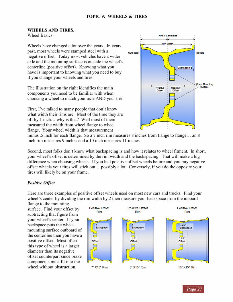
WHEELS AND TIRES.
Wheel Basics:
Wheels have changed a lot over the years. In years
past, most wheels were stamped steel with a
negative offset. Today most vehicles have a wider
axle and the mounting surface is outside the wheel’s
centerline (positive offset). Knowing what you
have is important to knowing what you need to buy
if you change your wheels and tires.
The illustration on the right identifies the main
components you need to be familiar with when
choosing a wheel to match your axle AND your tire.
First, I’ve talked to many people that don’t know
what width their rims are. Most of the time they are
off by 1 inch… why is that? Well most of them
measured the width from wheel flange to wheel
flange. Your wheel width is that measurement
minus .5 inch for each flange. So a 7 inch rim measures 8 inches from flange to flange… an 8
inch rim measures 9 inches and a 10 inch measures 11 inches.
Second, most folks don’t know what backspacing is and how it relates to wheel fitment. In short,
your wheel’s offset is determined by the rim width and the backspacing. That will make a big
difference when choosing wheels. If you had positive offset wheels before and you buy negative
offset wheels your tires will stick out… possibly a lot. Conversely, if you do the opposite your
tires will likely be on your frame.
Positive Offset
Here are three examples of positive offset wheels used on most new cars and trucks. Find your
wheel’s center by dividing the rim width by 2 then measure your backspace from the inboard
flange to the mounting
surface. Find your offset by
subtracting that figure from
your wheel’s center. If your
backspace puts the wheel
mounting surface outboard of
the centerline then you have a
positive offset. Most often
this type of wheel is a larger
diameter than its negative
offset counterpart since brake
components must fit into the
wheel without obstruction.
TOPIC 9: WHEELS & TIRES
Page 28
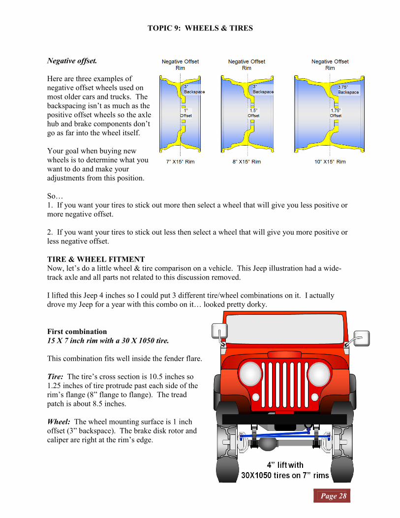
Negative offset.
Here are three examples of
negative offset wheels used on
most older cars and trucks. The
backspacing isn’t as much as the
positive offset wheels so the axle
hub and brake components don’t
go as far into the wheel itself.
Your goal when buying new
wheels is to determine what you
want to do and make your
adjustments from this position.
So…
1. If you want your tires to stick out more then select a wheel that will give you less positive or
more negative offset.
2. If you want your tires to stick out less then select a wheel that will give you more positive or
less negative offset.
TIRE & WHEEL FITMENT
Now, let’s do a little wheel & tire comparison on a vehicle. This Jeep illustration had a wide-
track axle and all parts not related to this discussion removed.
I lifted this Jeep 4 inches so I could put 3 different tire/wheel combinations on it. I actually
drove my Jeep for a year with this combo on it… looked pretty dorky.
First combination
15 X 7 inch rim with a 30 X 1050 tire.
This combination fits well inside the fender flare.
Tire: The tire’s cross section is 10.5 inches so
1.25 inches of tire protrude past each side of the
rim’s flange (8” flange to flange). The tread
patch is about 8.5 inches.
Wheel: The wheel mounting surface is 1 inch
offset (3” backspace). The brake disk rotor and
caliper are right at the rim’s edge.

TOPIC 9: WHEELS & TIRES
Page 29
Second combination
15 X 8 inch rim with a 32 X 1150 tire.
This combination fits inside the fender flare but the
outside of the tread patch is now at the edge of the
flare.
Tire: The tire’s cross section is 11.5 inches so 1.25
inches of tire protrude past each side of the rim’s
flange (9” flange to flange). The tread patch is about
9.5 inches.
Wheel: The wheel mounting surface is 1.5 inches
offset (3” backspace). The brake disk rotor and
caliper are roughly where they were for the 7 inch rim
(rim edge).
Third combination
15 X 10 inch rim with a 35 X 1250 tire.
With this combination your tire/wheel sticks beyond
the fender flare and part of the tread patch is now
outside edge of the flare. The tire height becomes an
issue for both body clearance and frame clearance
(turning).
Tire: The tire’s cross section is 12.5 inches so only
.75 of an inch of tire protrude past each side of the
rim’s flange (11” flange to flange). The tread patch
is about 11 inches. Unless you cut your fender wells,
you’ll probably need more lift to clear these tires off-
road without problems.
Wheel: The wheel mounting surface is 1.75 inches
offset (3.75” backspace). The backspacing was
increased to keep the wheel close to the original
position. The brake disk rotor and caliper are now
inside the rim.

TOPIC 10: DEATH WOBBLE--WHEEL BALANCE
Page 30
WHEEL (DEATH) WOBBLE AND WHEEL BALANCE.
One of the problems many of us will face from time to time is wheel wobble. It can be very
severe and cause loss of control.
What causes it? Well, it depends.
To diagnose the problem, you need to know the answer to these questions.
1. Does it wobble all the time?
If your answer is yes then you’ve got a steering part that is loose, broken, or worn out. Put your
vehicle on a lift and examine ball joints, tie rod ends, steering box, and hubs. One more place to
look is the suspension system. Dried, shrunken, or worn bushings can cause a wobble by letting
the entire axle to move. I’ll cover that later.
2. Does it wobble on all terrain?
If your answer is, “it does it on smooth terrain/roads,” then you need to do the same thing as the
previous condition. If your answer is, “it does it only on rough terrain/roads,” then look at your
steering linkage angles. You could have bump-steer. Bump-steer is most often noted on roads at
higher speeds but the effect off-road can be more pronounced by extreme lifting of the passenger
tire/wheel.
3. Does it wobble only at certain speeds?
If you steering wobbles at the same speed all the time and stops if you go faster or slower then
you have a balance problem. Let’s start with why larger wheels and tires are more of a problem
than the stock setup.
Taller, wider tire/rims.
Your stock rims and tires kept things close to the wheel/hub centerline, both in width and height.
The effect of yaw on your balance, while there, was not that noticeable. That assisted with
balance because all you really had to worry about was oscillation (vibration) on one axis (red
arrows) outward from the hub center.
This allowed balancing weights to be
applied to only the outside of the rim
(static balance) to counteract this
oscillation.
The other axis, yaw (blue arrows) was
always there but most of the time it wasn’t
significant enough to deal with so you
could get your tire/wheels statically
balanced. However, when you change to
taller, wider tires and wheels the yaw
effect is amplified.
TOPIC 10: DEATH WOBBLE--WHEEL BALANCE
Page 31
Here’s the tricky part. These oscillation effects will gradually grow as you approach the
resonance speed the decrease as you depart. The longer you stay at that speed the more the
effect will amplify itself. If the effect is only up and down you’ll experience vibration. If it is
yaw, you’ll experience shaking. In both cases, it becomes more and more severe until you speed
up or slow down.
Take your wheels to mechanic that can perform a dynamic balance on your wheels and insist that
they do it. Some service centers try to tell you it’s not needed but if you’ve got oversize
wheels/tires, it is.
OK, there are many things that can cause this imbalance such as losing a tread block, mud on the
inside of the rim, and spinning the tire on the wheel.
NOTE: Since rear axles are non-steering they don’t experience this Yaw effect and those wheels
could be static balanced. You won’t feel wobble, just vibration. If you intend to rotate your tires
you need get them dynamically balanced too.
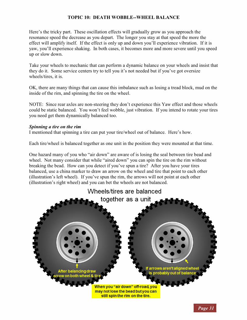
Spinning a tire on the rim
I mentioned that spinning a tire can put your tire/wheel out of balance. Here’s how.
Each tire/wheel is balanced together as one unit in the position they were mounted at that time.
One hazard many of you who “air down” are aware of is losing the seal between tire bead and
wheel. Not many consider that while “aired down” you can spin the tire on the rim without
breaking the bead. How can you detect if you’ve spun a tire? After you have your tires
balanced, use a china marker to draw an arrow on the wheel and tire that point to each other
(illustration’s left wheel). If you’ve spun the rim, the arrows will not point at each other
(illustration’s right wheel) and you can bet the wheels are not balanced.

TOPIC 11: COIL AND LINK SUSPENSION BASICS
Page 32
Since most of the Jeeps on the road today don’t use leaf springs, I decided to add this section.
The suspension requirements didn’t change, but technology did and the suspension design did.
There are some significant differences between the old and new technology. However, I stayed
with solid axles rather than cover independent suspensions. So in this section I’ll describe how a
coil and link suspension operates and from time to time I’ll highlight how that’s different from
the leaf spring suspension.
First, let’s start with an illustration of the stock Jeep Wrangler TJ suspension. I labeled the major
suspension and steering components on this bottom view. Like the leaf spring example, I’ve
colored most steering and suspension components blue. The addition, track bars (not needed for
leaf springs), are green.
Coil and link suspensions perform the same primary functions as leaf springs, but unlike leaf
springs, coil and link suspensions use three different components to hold the axles on the three
planes. Another major difference is the spring rate. While a leaf spring pack can have a
different spring rate for each leaf, most coils have one (sometimes two) spring rate.
I listed each component by the function it performs.
1) Coil springs: suspend the vehicle
2) Link arms: position the axle fore & aft
3) Track bars: maintain the axle side-to-side position (not needed with triangulated link
arms)
TOPIC 11: COIL AND LINK SUSPENSION BASICS
Page 33
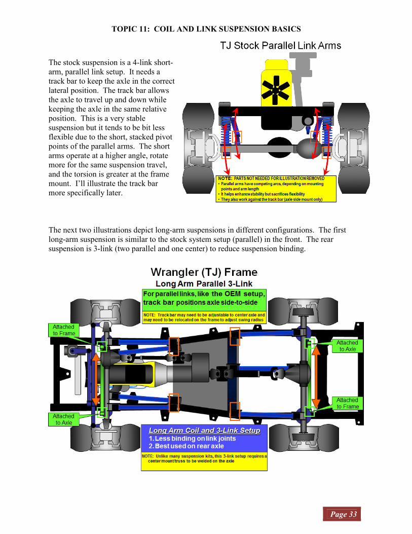
The stock suspension is a 4-link short-
arm, parallel link setup. It needs a
track bar to keep the axle in the correct
lateral position. The track bar allows
the axle to travel up and down while
keeping the axle in the same relative
position. This is a very stable
suspension but it tends to be bit less
flexible due to the short, stacked pivot
points of the parallel arms. The short
arms operate at a higher angle, rotate
more for the same suspension travel,
and the torsion is greater at the frame
mount. I’ll illustrate the track bar
more specifically later.
The next two illustrations depict long-arm suspensions in different configurations. The first
long-arm suspension is similar to the stock system setup (parallel) in the front. The rear
suspension is 3-link (two parallel and one center) to reduce suspension binding.
TOPIC 11: COIL AND LINK SUSPENSION BASICS
Page 34
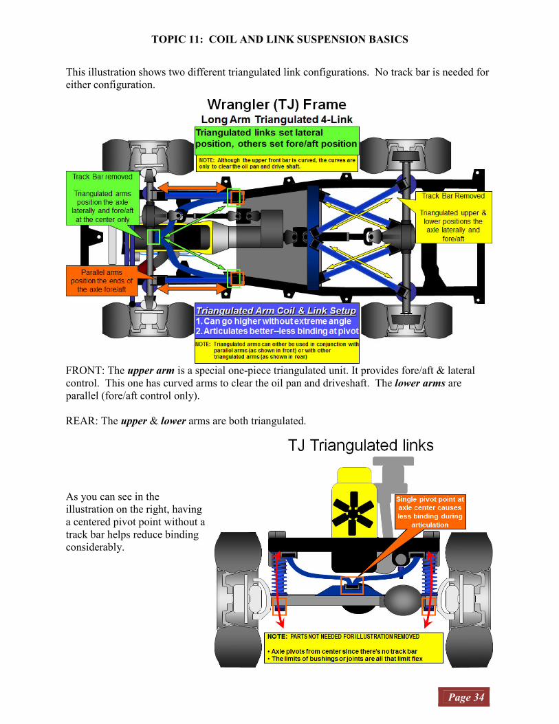
This illustration shows two different triangulated link configurations. No track bar is needed for
either configuration.
FRONT: The upper arm is a special one-piece triangulated unit. It provides fore/aft & lateral
control. This one has curved arms to clear the oil pan and driveshaft. The lower arms are
parallel (fore/aft control only).
REAR: The upper & lower arms are both triangulated.
As you can see in the
illustration on the right, having
a centered pivot point without a
track bar helps reduce binding
considerably.

TOPIC 11: COIL AND LINK SUSPENSION BASICS
Page 35
These two illustrations are provided to show the difference in link-arm angles. Both suspensions
are the same height but one is a long-arm kit and the other is a short-arm kit. That affects the
swing arc the axle will take as the spring compresses and extends.
When you have tall springs, a short-arm suspension’s swing arc is more angled; forward/up and
rearward/down than a similar height long-arm suspension.
It’s also important to note that the axle travels in a slight arc versus the leaf spring suspension’s
straight line. The leaf spring pack lengthens and shortens, while the link arm maintains a
constant length.
Bent (angled) link-arms: Just like the drag link mentioned earlier, the only reason to have bent
link arms is to avoid striking other components or obstacles.
TOPIC 11: COIL AND LINK SUSPENSION BASICS
Page 36
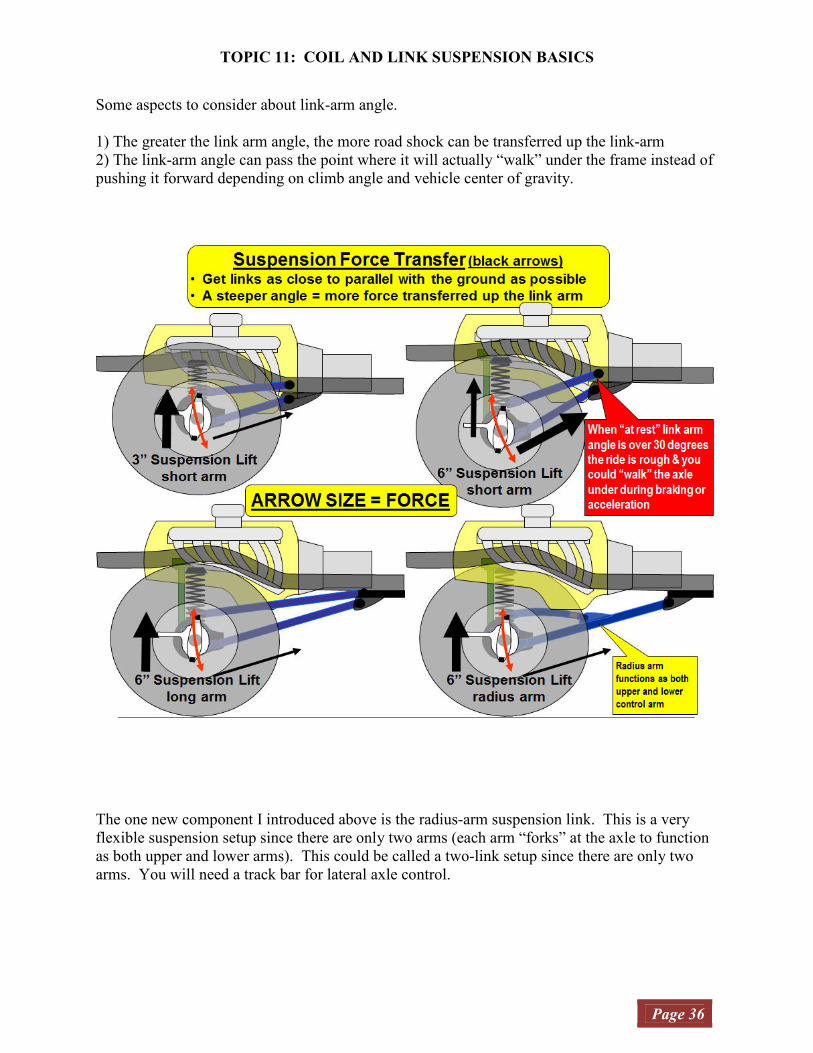
Some aspects to consider about link-arm angle.
1) The greater the link arm angle, the more road shock can be transferred up the link-arm
2) The link-arm angle can pass the point where it will actually “walk” under the frame instead of
pushing it forward depending on climb angle and vehicle center of gravity.
The one new component I introduced above is the radius-arm suspension link. This is a very
flexible suspension setup since there are only two arms (each arm “forks” at the axle to function
as both upper and lower arms). This could be called a two-link setup since there are only two
arms. You will need a track bar for lateral axle control.

TOPIC 11: COIL AND LINK SUSPENSION BASICS
Page 37
The final comparison to a CJ is how the steering links are arranged.
NOTE: The stock Wrangler TJ track bars are bent to avoid striking the differential cases, as
illustrated above.
The steering setup for TJs and CJs is very different. The TJ draglink connects to the tie rod
versus the draglink connecting to the steering knuckle (CJ).
As illustrated above, the angles for the draglink and track bar are nearly the same, because of the
tie rod connection. In this setup, the axle moves left or right in parallel with the drag link. This
parallel motion keeps the axle and tie rod links in the same relative position, minimizing bump-
steer.
The axle will move left/right further as you lift it higher unless you relocate the track bar lower
as you add more lift. In addition, the track bar drag link relationship is important. If you install
a drop Pitman arm, you must install a similar length track bar relocation bracket to keep their
relative pivot paths the same.

CONCLUSION
Page 38
While I covered a lot of the topics I see on countless repeated threads in the tech forums, I
couldn’t cover them all. And like I said earlier, this isn’t intended to be a “how to” article. Its
focus was to explain concepts and provide some background for your troubleshooting effort.
There are many other aspects of steering, suspension, driveline, and wheels/tires that I could
cover but they often require a specialist and special equipment. I also didn’t cover steering
topics such as Steering Axis Inclination, Included Angle, Scrub Radius, Thrust Angle, and Toe
Out on Turns. Likewise, I didn’t cover link angle calculation, including squat or anti-squat,
since most of you aren’t building a coil/link suspension from scratch. If I see questions on those
topics appearing a lot on the forums, I’ll add them to the article.
I hope this gives you a better understanding of what you can expect. If you can’t fix it, you can
explain it to someone that can.
Gojeepin,
Mike