steering control system for autonomous tractor
TRANSCRIPT

Proceedings of the 7th JFPS InternationalSymposium on Fluid Power, TOYAMA 2008
September 15-18, 2008
OS1-2
STEERING CONTROL SYSTEM FOR AUTONOMOUS
TRACTOR
Keiichi INOUE*
*Lowland Crop Rotation Research Team ,National Agriculture Research Center for Hokkaido Region
1 Hitsujigaoka, Toyohira-ku, Sapporo, 062-8555 Japan
(E-mail: [email protected])
ABSTRACT
An automatic power steering control system is modified to a tractor of 66kw engine power and using a navigationsystem of optical fiber gyroscope(IMU) and real-time kinematic GPS which are hybrid combined, the movement of thevehicle in the field is analyzed dynamically using a kinetic movement model of tractor to determine the parameters ofthe model. The tractor equipped with a planter was successfully controlled and was able to trace the target line correctlywithin 10cm by the method of adaptive travel control using the movement model of the vehicle considering thehydraulic time delay of the power steering mechanism.
KEY WORDS
Steering Control, Autonomous,Tractor,, Vehicle modeling, Filtering,
NOMENCLATURE
ƒÕ: Vehicle running directionƒÆ
: Direction of vehicle body center lineƒ³
: Steering angle
Kf: Cornering power of front wheel
Kf: Cornering power of rear wheael
v: velocity of vehicle
ƒÀ: Slip angle 2L,
ă: Time rag of hydraulic operation
ƒÖ: Rotational rateƒÊ
: Rolling resistance
• Ow: wheel base (suffces f:front, r:rear)
m: Mass of vehicle
INTRODUCTION
The speedup of the work is gradually highly required
with the extension of the size of operational holdings per
one farmer. However, the need for accurately controlling
the implement becomes inevitable. Automatically steeredfarm equipment has many advantages of increasing
agriculture accuracies at high speed operation includingrelieving the driver of the tedious task of accurately
steering the vehicle, operation in low visibilitycircumstances such as at night. Many agriculturaloperations pull towed implements. It will become
necessary to accurately control towed implements.Tracked tractors are now used increasingly among
farmers in Japan because of its soft compaction, strongfraction force, ability to work on the weak ground and
stability in the high-speed field work. The operabilityand steering mechanism are constructed, and the runningand turning performance is fairly improved nowadays.
The operation is possible of the sense which is similar tothe wheel tractor, and possible to work comfortable.
However heading control of tracked vehicles at highspeed is difficult for automatic driving or human driving
with high accuracy because of the slippage between thecrawlers and the ground. There has also been work done
53 Copyright (c) 2008 by JFPS, ISBN 4-931070-07-X
on the control of wheel tractor implements, using GPSmeasurements, although there are no details on the modeland control algorithms for the tracked tractors orsemi-crawler tractor.This paper describes a modeling of the steering actuationof a crawler tractor and a semi-crawler tractor and anextended Kalman filter to estimate the position, direction,attitude, speed of the tractor required for the statefeedback algorithm and robustic adaptive control methodof the electro-hydraulic system of the tractor. Thelinearization of the tractor-implement model is validatedthrough a series of the line tracking experiments on asemi-crawler tractor and a planter.
METHOD
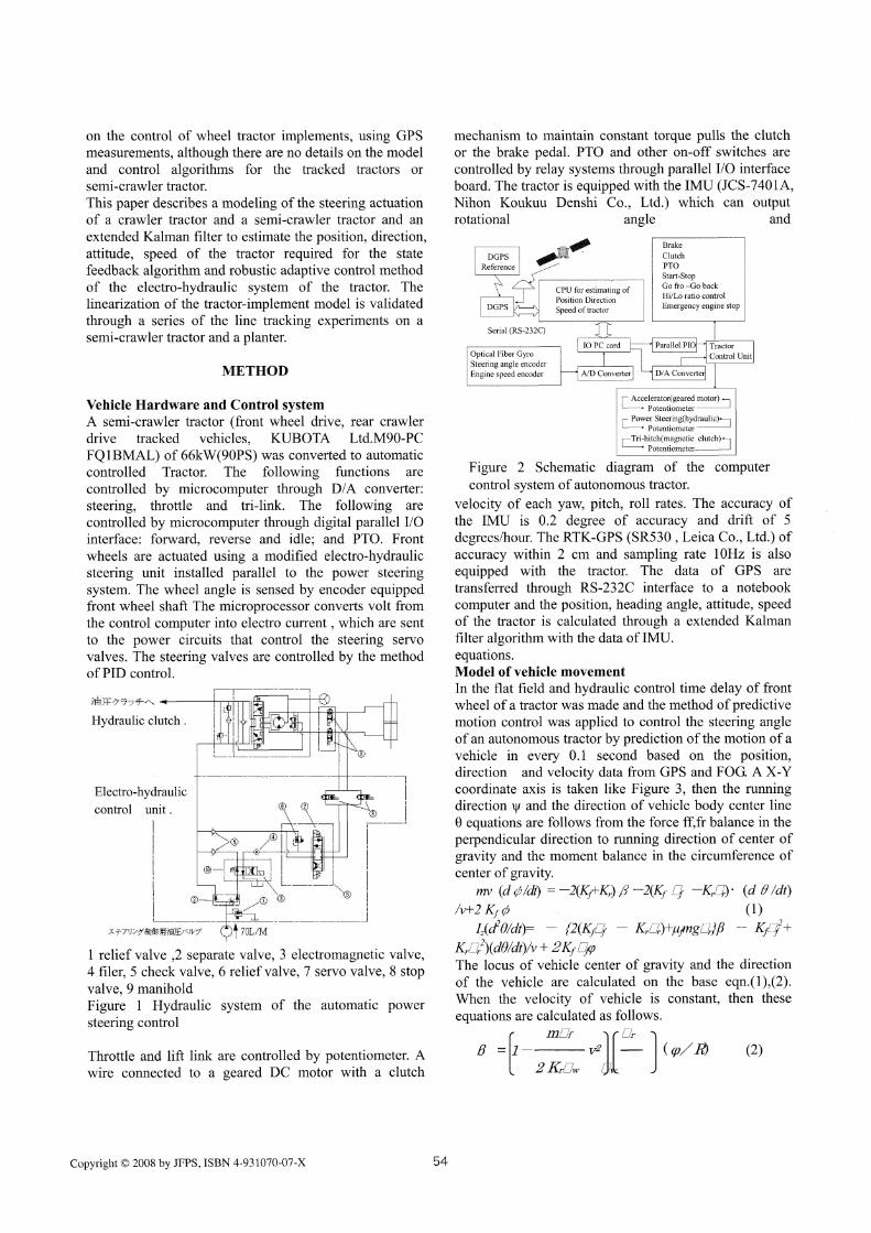
Vehicle Hardware and Control systemA semi-crawler tractor (front wheel drive, rear crawlerdrive tracked vehicles, KUBOTA Ltd.M90-PCFQ 1 BMAL) of 66kW(90PS) was converted to automaticcontrolled Tractor. The following functions arecontrolled by microcomputer through D/A converter:steering, throttle and tri-link. The following arecontrolled by microcomputer through digital parallel I/Ointerface: forward, reverse and idle; and PTO. Frontwheels are actuated using a modified electro-hydraulicsteering unit installed parallel to the power steeringsystem. The wheel angle is sensed by encoder equippedfront wheel shaft The microprocessor converts volt fromthe control computer into electro current , which are sentto the power circuits that control the steering servovalves. The steering valves are controlled by the methodof PID control.
1 relief valve ,2 separate valve, 3 electromagnetic valve,4 filer, 5 check valve, 6 relief valve, 7 servo valve, 8 stop
valve, 9 maniholdFigure 1 Hydraulic system of the automatic power
steering control
Throttle and lift link are controlled by potentiometer. Awire connected to a geared DC motor with a clutch
mechanism to maintain constant torque pulls the clutchor the brake pedal. PTO and other on-off switches arecontrolled by relay systems through parallel I/O interfaceboard. The tractor is equipped with the IMU (JCS-7401A,Nihon Koukuu Denshi Co., Ltd.) which can outputrotational angle and
Figure 2 Schematic diagram of the computercontrol system of autonomous tractor.
velocity of each yaw, pitch, roll rates. The accuracy ofthe IMU is 0.2 degree of accuracy and drift of 5degrees/hour. The RTK-GPS (SR530 , Leica Co., Ltd.) ofaccuracy within 2 cm and sampling rate 10Hz is alsoequipped with the tractor. The data of GPS aretransferred through RS-232C interface to a notebookcomputer and the position, heading angle, attitude, speedof the tractor is calculated through a extended Kalmanfilter algorithm with the data of IMU.equations.Model of vehicle movementIn the flat field and hydraulic control time delay of frontwheel of a tractor was made and the method of predictivemotion control was applied to control the steering angleof an autonomous tractor by prediction of the motion of avehicle in every 0.1 second based on the position,direction and velocity data from GPS and FOG. A X-Ycoordinate axis is taken like Figure 3, then the runningdirection y and the direction of vehicle body center line0 equations are follows from the force ff,fr balance in the
perpendicular direction to running direction of center ofgravity and the moment balance in the circumference ofcenter of gravity.
(1)
The locus of vehicle center of gravity and the directionof the vehicle are calculated on the base eqn.(1),(2).When the velocity of vehicle is constant, then theseequations are calculated as follows.
(2)
Copyright (c) 2008 by JFPS, ISBN 4-931070-07-X 54

(3)
(4)Steering control method
The steering angle ƒÕ(k) is controlled so as to trace the
target line Y-axis. The direction Į' and x' after short time
X. second are estimated with the eqn.(6),(7). The ƒÕ(k) is
controlled so as to follow eqn.(5) relation. This eqn.' s
relation means the direction of the vehicle is to
proportional to the offset of the vehicle.
(5)Where,
(6)
(7)
ƒÕ(k) and ƒÖ(k) are small, so approximately replaced as
follows eqn.
(8)So, objective steering angle ƒÕi(k) is obtained from
(5)-(8)eqn.
(9)
Where, (10)
Using a simulation model for a tractor mobile trace, afterexamining several functions f (x', v), determined whenstrait traveling,
(11)There is a relationship of dy/dx= 1/ tanĮ, so if we
suppose that Eq. (5) is satisfied, then the traveling trace
is calculated by solving the differential equation of dy/
dx= 1 / tan (f(x, v)). The relationship between offset x
and vehicle direction 0' for vehicle control in strait
traveling is expressed by Eq. (5).These parameters were
fixed in the experiment.
Figure 3 Schematic diagram of movement of
tractor.
Experiment of automatic planting in the fieldThe semi-crawler tractor of 66kW(90 PS) was developedin our laboratory (Figure 4). After equipping this tractorwith a planter for soybeans 2.52 m in work width, weconducted an experiment of automatic planting in the
fi eld 10•~385 m in area at 1.3 m/s in travel speed
(engine: 1800 rpm). At the end of the field, the system
calculated target steering angle and executed a turn to
bring the tractor assembly to the next ridge. After
directing the tractor to the next ridge, the system
measured the position and direction by FOG, GPS and
collected the direction offset of the fiber-optic gyro
output.
Fi gure 4 Autonomous Semi-crawler tractor
RESULT and DISCUSSION
Responsibility of hydraulic steering control systemThe response of the hydraulic power steering control
system is shown in Figure 5 when the target steeringangle is 10degree and initial steering angle is 0 degree.
The steering angle is controlled linearly and controlledwithin 1 second. The idling time rag is about
0.2second.The process of the output volt from thecomputer PID control and measured steering angle is
shown in Figure 6.
Figure 5 Response of electro-hydraulic power
steering by PID control
55 Copyright (C) 2008 by JFPS, ISBN 4-931070-07-X
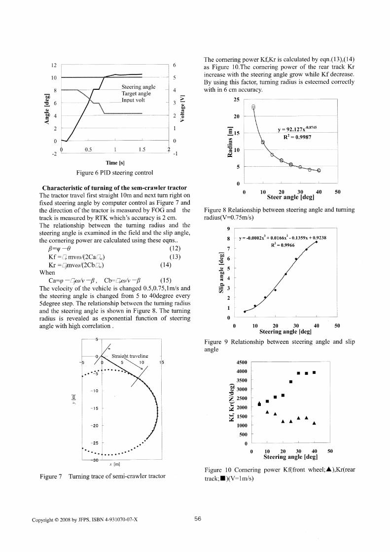
Figure 6 PID steering control
Characteristic of turning of the sem-crawler tractor
The tractor travel first straight 10m and next turn right onfixed steering angle by computer control as Figure 7 andthe direction of the tractor is measured by FOG and the
track is measured by RTK which's accuracy is 2 cm.The relationship between the turning radius and the
steering angle is examined in the field and the slip angle,the cornering power are calculated using these eqns..
β=Ψ-θ (12)Kf=□rmvω/(2Ca□w) (13)Kr=□fmvω/(2Cb□w) (14)
When
Ca=ρ-□fω/v-β,Cb=□rω/v-β (15)The velocity of the vehicle is changed 0.5,0.75,1m/s andthe steering angle is changed from 5 to 40degree every5degree step. The relationship between the turning radius
and the steering angle is shown in Figure 8. The turningradius is revealed as exponential function of steering
angle with high correlation.
Figure 7 Turning trace of semi-crawler tractor
The cornering power Kf,Kr is calculated by eqn.(13),(14)as Figure 10.The cornering power of the rear track Krincrease with the steering angle grow while Kf decrease.By using this factor, turning radius is esteemed correctlywith in 6 cm accuracy.
Figure 8 Relationship between steering angle and turningradius(V=0.75m/s)
Figure 9 Relationship between steering angle and slipangle
Figure 10 Cornering power Kf(front wheel;A),Kr(rear
track;•¡)(V=1 m/s)
Copyright (c) 2008 by JFPS, ISBN 4-931070-07-X 56

Simulation of the steering control and movement ofvehicleThe result of simulation of the movement of thesemi-crawler tractor by the predictive steering controlmethod is shown in Figure 8. The steering angle iscalculated considering the hydraulic cylinder'soperational time lag and direction swinging which issupposed to occur by inequalities of the ground. Figure11 show steering angle, direction of vehicle, x-positiondifference from the target line by adjusting predictingtime lag. The tractor is more adequately controlled bypredictive time 1 s than 0.5s7s.
Figure 11 Comparison of dynamics for path tracking ofvehicle between the predictive time o.5s(upper) and1s(lower)
Automatic planting in the fieldThe tractor plant soybeans automatically by the roundtrip work of the straight distance 380m without thetrouble at 1.3m/s speed for more than 30 minutes
(experiment time).Each lines is parallel and almost straight with equalinterval. The tractor was controlled within 10 cm (RMS5.2cm)of accuracy(Figure 12-14). The tractor raise upplanter and turn to next line automatically at the end ofthe operation area and select next target line which isgenerated by computer, and adjust the position anddirection, after entering operational area, down planterand raise up engine revolution, and go forth. There is nomeandering under the method of forecasting a positionand direction of tractor. The traces of the seeding were
parallel and equal to the target line and the edge of thetrace was almost same.
Figure 12 Track of autonomous tractor working on
planting
Figure 13 Track of the autonomous tractor working ofplanting( target line and actual track)
Figure 14 Offset x track of autonomous semi-crawlertractor
57 Copyright (c) 2008 by JFPS, ISBN 4-931070-07-X

Figure 15 Planting soybeans by autonomoussemi-crawler tractor (2007.5.29)
Automatic Manual
Figure 16 Comparison of plant raw (soybean) byautomatic and manual operation
REFERENCES
1. Kobayashi, K. et al. Accurate Navigation viaDifferential GPS and Vehicle Local Sensors. Proceedingof the IEEE International Conf. on MFI, 9-16,19942. Kise. M, Noguchi. N, lshii. K, Terao. H, The developmentof the Autonomous Tractor with Steering ControlApplied by Optimal Control, Proceeding of the ATOEconference, 367-363, 20023. Keiich, Inoue., K. Otsuka,M. Sugimoto,N.Murakami, Wen Li, Sensor fusionTechniques for Automatic Guidance by the method ofKalman filter using DGPS andGyrocompass (Partl), Vo161, No.4, 103-113, JSAM4. M. Ahmadi, V. Polotski and R. Hurteau:"PathTracking Control of Tracked Vehicles.", In proc IEEE Int.Conf. On Robotics and Automation, pp.2938-2943,2000.5. Z. Janosi and B. Hanamoto,The analyticaldetermination of drawbar pull as a function of slip fortracked vehicles", In proc. 1st Int. Conf. OnTerrain-Vehicle Systems, pp.707-736, 1961.6. G. Bekker, Introduction to Terrain-Vehicle Systems,University of Michigan Press, 1969.
7. Kazutaka TAKAHASHI Minoru MUTO, Masamitsu
KURISU, A Consideration about Estimation of TheSlippage for Running Tracked Vehicles, Proceeding of
JSME Conference on Robotics and Mechatronics,2A1-L1-68, 2004
Copyright (c) 2008 by JFPS, ISBN 4-931070-07-X 58