steelworker volume 2 training manual
TRANSCRIPT

DISTRIBUTION STATEMENT A: Approved for public release; distribution is unlimited.
NONRESIDENTTRAININGCOURSE
November 1996
Steelworker, Volume 2
NAVEDTRA 14251

DISTRIBUTION STATEMENT A: Approved for public release; distribution is unlimited.
Although the words “he,” “him,” and“his” are used sparingly in this course toenhance communication, they are notintended to be gender driven or to affront ordiscriminate against anyone.

COMMANDING OFFICERNETPDTC
6490 SAUFLEY FIELD RDPENSACOLA, FL 32509-5237
ERRATA #1 29 May 2001
Specific Instructions and Errata forNonresident Training Course
STEELWORKER, VOLUME 2, NAVEDTRA 14251
1. This errata supersedes all previous errata. No attempt has been made toissue corrections for errors in typing, punctuation, etc., that do not affectyour ability to answer the question or questions.
2. To receive credit for deleted questions, show this errata to your localcourse administrator (ESO/scorer). The local course administrator is directedto correct the course and the answer key by indicating the questions deleted.
3. Assignment Booklet, NAVEDTRA 14251.
Delete the following questions, and leave the corresponding spaces blankon the answer sheets:
Questions Questions
2-44 5-123-16 6-313-17 7-233-18 7-554-45 8-514-52 8-524-55


i
PREFACE
By enrolling in this self-study course, you have demonstrated a desire to improve yourself and the Navy.
Remember, however, this self-study course is only one part of the total Navy training program. Practical
experience, schools, selected reading, and your desire to succeed are also necessary to successfully round
out a fully meaningful training program.
COURSE OVERVIEW: In completing this nonresident training course, you will demonstrate a
knowledge of the subject matter by correctly answering questions on the following subjects:
Technical Administration
Layout and Fabrication of Sheet Metal and Fiberglass Duct
Structural Terms/Layout and Fabrication of Structural Steel and Pipe
Fiber Line
Wire Rope
Rigging
Reinforcing Steel
Pre-engineered Structures: Buildings, K-Spans, Towers, and Antennas
Pre-engineered Storage Tanks
Pontoons
Pre-engineered Structures: Short Airfield for Tactical Support
Steelworker Tools and Equipment
THE COURSE: This self-study course is organized into subject matter areas, each containing learning
objectives to help you determine what you should learn along with text and illustrations to help you
understand the information. The subject matter reflects day-to-day requirements and experiences of
personnel in the rating or skill area. It also reflects guidance provided by Enlisted Community Managers
(ECMs) and other senior personnel, technical references, instructions, etc., and either the occupational or
naval standards, which are listed in the Manual of Navy Enlisted Manpower Personnel Classifications
and Occupational Standards, NAVPERS 18068.
THE QUESTIONS: The questions that appear in this course are designed to help you understand the
material in the text.
VALUE: In completing this course, you will improve your military and professional knowledge.
Importantly, it can also help you study for the Navy-wide advancement in rate examination. If you are
studying and discover a reference in the text to another publication for further information, look it up.
1996 Edition Prepared by
SWC Michael P. DePumpo
Published by
NAVAL EDUCATION AND TRAINING
PROFESSIONAL DEVELOPMENT
AND TECHNOLOGY CENTER
NAVSUP Logistics Tracking Number
0504-LP-026-8850

ii
Sailor’s Creed
“I am a United States Sailor.
I will support and defend theConstitution of the United States ofAmerica and I will obey the ordersof those appointed over me.
I represent the fighting spirit of theNavy and those who have gonebefore me to defend freedom anddemocracy around the world.
I proudly serve my country’s Navycombat team with honor, courageand commitment.
I am committed to excellence andthe fair treatment of all.”

CONTENTS
CHAPTER PAGE1.2.3.4.5.6.7.8.9.
10.11.12.
Technical Administration . . . . . . . . . . . . . . . . . . . . . .1-1Layout and Fabrication of Sheet Metal and Fiber-glass Duct . . . .2-1Structural Steel Terms/Layout and Fabrication of Structural Steeland Pipe . . . . . . . . . . . . . . . . . . . . . . . . . . . . . . .. . . . . . . . . . . . . . . . . . . . . . . . . . . .3-1Fiber Line, . . . . . . . . . . . . . . . . . . . . . . . . . . . . .4-1Wire Rope . . . . . . . . . . . . . . . . . . . . . . . . . . . . . .5-1Rigging . . . . . . . . . . . . . . . . . . . . . . . . . . . . . . .6-1Reinforcing Steel . . . . . . . . . . . . . . . . . . . . . . . . . . .7-1Pre-engineered Structures: Buildings, K-Spans, Towers,and Antennas . . . . . . . . . . . . . . . . . . . . . . . . . . . . . 8-1Pre-engineered Storage Tanks . . . . . . . . . . . . . . . . . . . 9-1Pontoons . . . . . . . . . . . . . . . . . . . . . . . . . . . . . .. . . . . . . . . . . 10-1Pre-engineered Structures: Short Airfield for Tacticalsupport . . . . . . . . . . . . . . . . . . . . . . . . . . . . . . . . . . . . . . . . . . . . . . . . . ..11-1Steelworker Tools and Equipment . . . . . . . . . . . . . . . . . 12-1
APPENDIXI. Glossary . . . . . . . . . . . . . . . . . . . . . . . . . . . . . . . AI-1
II. Mathematics . . . . . . . . . . . . . . . . . . . . . . . . . . . . AII-1III. Metric Conversion Tables. . . . . . . . . . . . . . . . . . . . . AIII-1IV.HandSignals . . . . . . . . . . . . . . . . . . . . . . . . . . AIV-1V. References Used to Develop This TRAMAN . . . . . . . . . . . AV-1
INDEX . . . . . . . . . . . . . . . . . . . . . . . . . . . . . . .. INDEX-1
iii

CHAPTER 7
REINFORCING STEEL
As a Steelworker, you must be able to cut, bend,place, and tie reinforcing steel. This chapter describesthe purpose of reinforcing steel in concreteconstruction, the types and shapes of reinforcing steelcommonly used, and the techniques and tools used bySteelworkers in rebar (reinforcing steel) work. Thischapter begins with a presentation of fundamentalinformation about concrete to help you understandrebar work fully.REINFORCED CONCRETE
As a Steelworker you will be primarily concernedwith reinforcing steel placement but you should tosome extent, be concerned with concrete as well.Concrete with reinforcing steel added becomesreinforced concrete. Structures built of reinforcedconcrete, such as retaining walls, buildings, bridges,highway surfaces, and numerous other structures, arereferred to as reinforced concrete structures orreinforced concrete construction.CONCRETE MATERIALS
Concrete is a synthetic construction material madeby mixing cement, fine aggregate (usually sand),coarse aggregate (usually gravel or crushed stone),and water in proper proportions. This mixture hardensinto a rocklike mass as the result of a chemical reactionbetween the cement and water. Concrete will continueto harden and gain strength as long as it is kept moistand warm. This condition allows the chemical reactionto continue and the process is known as curing.Durable, strong concrete is made by the correctproportioning and mixing of the various materials andby proper curing after the concrete is placed.The correct proportioning of the concreteingredients is often referred to as the mix. The qualityof the concrete is largely determined by the quality ofthe cement-water paste that bonds the aggregatestogether. The strength of concrete will be reduced ifthis paste has water added to it. The proportion ofwater to cement is referred as the water-cement ratio.The water-cement ratio is the number of gallons ofwater per pounds of cement. High-quality concrete is
7-1
produced by using the lowest water-cement mixturepossible without sacrificing workability.Because concrete is plastic when it is placedforms are built to contain and form the concrete untilit has hardened In short forms and formwork aredescribed as molds that hold freshly placed concretein the desired shape until it hardens. All the ingredientsof the mix are placed in a concrete mixer, and after athorough mixing, the concrete is transferred bynumerous methods, such as by bucket, bywheelbarrow, and so forth, into the formwork in whichthe reinforcing steel has already been placed.Concrete reaches its initial set in approximately 1hour under normal conditions and hardens to its finalset in approximately 6 to 12 hours. Before the initialset, concrete must be placed in the forms and vibratedto consolidate it into the formwork and ensurecomplete coverage of all reinforcing bars. Finishoperations, such as smooth troweled finishes, must beperformed between initial and final set. After the finalset, concrete must be protected from shock, extremetemperature changes, and premature drying until itcures to sufficient hardness. Concrete will beself-supportive in a few days and attain most of itspotential strength in 28 days of moist curing. Forfurther information on concrete, refer to Builder 3 &2, Volume 1, NAVEDTRA 12520.
CONCRETE STRENGTH
As stated previously, the strength of concrete isdetermined by the water-cement ratio. The strength ofready-mixed concrete ranges from 1,500 to about5,000 pounds per square inch (psi); and, with furtherattention paid to proportioning, it can go even higher.Under usual construction processes, lower strengthconcrete will be used in footers and walls and higherstrength in beams, columns, and floors. The requiredstrength of concrete on a given project can be foundin the project plans and specifications for a specificproject.NOTE: Quality control is important to ensurespecific design requirements are met. If the designspecifications do not meet minimum standards,structural integrity is compromised and the structure

is considered unsafe. For this reason, the compressivestrength of concrete is checked on all projects.The strength of the concrete is checked by the useof cylindrical molds that are 6 inches in diameter and12 inches in height. Concrete samples must be takenon the jobsite from the concrete that is being placed.After being cured for a time period that rangesbetween 7 to 28 days, the cylinders are “broken tofailure” by a laboratory crushing machine thatmeasures the force required for the concrete to fail.For further information on concrete strength andtesting, refer to Engineering Aid 3, NAVEDTRA10696, and NAVFAC MO 330. (The MO 330 shouldbe maintained in a battalion’s tech library.)
PURPOSES AND TYPES OF
REINFORCING STEEL
Reinforced concrete was designed on the principlethat steel and concrete act together in resisting force.Concrete is strong in compression but weak intension. The tensile strength is generally rated about10 percent of the compression strength. For thisreason, concrete works well for columns and posts thatare compression members in a structure. But, when itis used for tension members, such as beams, girders,foundation walls, or floors, concrete must bereinforced to attain the necessary tension strength.Steel is the best material for reinforcing concretebecause the properties of expansion for both steel andconcrete are considered to be approximate] y the same;that is, under normal conditions, they will expand andcontract at an almost equal rate.NOTE: At very high temperatures, steel expandsmore rapidly than concrete and the two materials willseparate.Another reason steel works well as areinforcement for concrete is because it bonds wellwith concrete. This bond strength is proportional tothe contact surface of the steel to the concrete. In otherwords, the greater the surface of steel exposed to theadherence of concrete, the stronger the bond. Adeformed reinforcing bar adheres better than a plain,round, or square one because it has a greater bearingsurface. In fact, when plain bars of the same diameterare used instead of deformed bars, approximately 40percent more bars must be used.The rougher the surface of the steel, the better itadheres to concrete. Thus steel with a light, firm layerof rust is superior to clean steel; however, steel with
loose or scaly rust is inferior. Loose or scaly rust canbe removed from the steel by rubbing the steel withburlap or similar material. This action leaves only thefirm layer of rust on the steel to adhere to the concrete.NOTE: Reinforcing steel must be strong intension and, at the same time, be ductile enough to beshaped or bent cold.Reinforcing steel can be used in the form of barsor rods that are either plain or deformed or in the formof expanded metal, wire, wire fabric, or sheet metal.Each type is useful for different purposes, andengineers design structures with those purposes inmind.Plain bars are round in cross section. They areused in concrete for special purposes, such as dowelsat expansion joints, where bars must slide in a metalor paper sleeve, for contraction joints in roads andrunways, and for column spirals. They are the leastused of the rod type of reinforcement because theyoffer only smooth, even surfaces for bonding withconcrete.Deformed bars differ from the plain bars in thatthey have either indentations in them or ridges onthem, or both, in a regular pattern. The twisted bar, forexample, is made by twisting a plain, square bar cold.The spiral ridges, along the surface of the deformedbar, increase its bond strength with concrete. Otherforms used are the round and square corrugated bars.These bars are formed with projections around thesurface that extend into the surrounding concrete andprevent slippage. Another type is formed withlongitudinal fins projecting from the surface toprevent twisting. Figure 7-1 shows a few of the typesof deformed bars available. In the United States,deformed bars are used almost exclusively; while inEurope, both deformed and plain bars are used.
Figure 7-1.—Various types of deformed bars.
7-2

Eleven standard sizes of reinforcing bars are in use rebar could be procured locally and could be metric.today. Table 7-1 lists the bar number, area in square Table 7-3 is given for comparison. Remember that barinches, weight, and nominal diameter of the 11 standard numbers are based on the nearest number ofsizes. Bars No. 3 through 11 and 14 and 18 are all one-eighth inch included in the nominal diameter ofdeformed bars. Table 7-2 lists the bar number, area in the bar. To measure rebar, you must measure acrosssquare inches and millimeters, weight in pounds per foot the round/square portion where there is noas well as kilograms per meter, and nominal diameter of deformation. The raised portion of the deformation isthe 8 standard metric sizes. At various sites overseas, not measured when measuring the rebar diameter.Table 7-1.—U.S. Standard Reinforcing Bars
U.S. Standard Reinforcing Steel Bars
Bar Size Area Square Weight lb Diameter
Designation Inches Per Footinches mm
#3 .11 .376 .375 9.53#4 .20 .668 .500 12.7#5 .31 1.043 .625 15.88#6 .44 1.502 .750 19.05#7 .60 2.044 .875 22.23#8 .79 2.670 1.000 25.40#9 1.00 3.400 1.128 28.58#10 1.27 4.303 1.270 31.75#11 1.56 5.313 1.410 34.93#14 2.25 7.650 1.693 43.00#18 4.00 13.600 2.257 57.33
Table 7-2.—Metric Reinforcing Bars
METRIC REINFORCING STEEL BARS
BAR SIZE AREA WEIGHT DIAMETER
DESIGNATIONSq. Inches Sq. mm Lb Per Ft KG/M Inches mm
10m .16 100 .527 .785 .445 11.315m .31 200 1.054 2.355 .630 16.020m .47 300 1.563 2..355 .768 19.525m .78 500 2.606 3.925 .992 25.230m 1.09 700 3.649 5.495 1.177 29.935m 1.55 1000 5.213 7.850 1.406 35.745m 2.33 1500 7.820 11.775 1.710 43.755m 3.88 2500 13.034 19.625 2.220 56.4
7-3

Table 7-3.—Comparison of U.S. Customary and Metric Rebar
U.S. Standard Bar Metric Bar Metric
Bar is:Bar Size Area Sq. Inches Bar Size Area Sq. Inches
#3 .11 10m .16 45% larger*#4 .20 10m .16 20% smaller#4 .20 15m .31 55% larger#5 .31 15m .31 Same#6 .44 .47 6.8% larger#7 .60 .47 22% smaller#7 .60 .25m .78 30% larger#8 .79 25m .78 1.3% smaller#9 1.00 30m 1.09 9% larger
#10 1.27 30m 1.09 14% smaller#10 1.27 35m 1.55 22% larger#11 1.56 35m 1.55 0.6% smaller#14 2.25 45m 2.33 3 .5% larger#18 4.00 55m 3.88 3 .0% smaller
*NOTE: % Difference is based upon area of rebar in square inches.
Reinforcing Bars
Reinforcing bars are hot-rolled from a variety ofsteels in several different strength grades. Mostreinforcing bars are rolled from new steel billets, butsome are rolled from used railroad-car axles orrailroad rails that have been cut into rollable shapes.An assortment of strengths are available.The American Society for Testing Materials(ASTM) has established a standard branding fordeformed reinforcing bars. There are two generalsystems of bar branding. Both systems serve the basic
purpose of identifying the marker size, type of steel,and grade of each bar. In both systems an identity markdenoting the type of steel used is branded on every barby engraving the final roll used to produce the bars soas to leave raised symbols between the deformations.The manufacturer’s identity mark that signifies themill that rolled the bar is usually a single letter or, insome cases, a symbol. The bar size follows themanufacturer’s mark and is followed by a symbolindicating new billet steel (-N-), rolled rail steel (-I-),
or rolled axle steel (-A-). Figure 7-2 shows thetwo-grade marking system.The lower strength reinforcing bars show onlythree marks: an initial representing the producingmill, bar size, and type of steel. The high strengthreinforcing bars use either the continuous line systemor the number system to show grade marks. In the linesystem, one continuous line is rolled into the60,000 psi bars, and two continuous lines are rolledinto the 75,000 psi bars. The lines must run at leastfive deformation spaces, as shown in figure 7-2. In thenumber system, a “60” is rolled into the bar followingthe steel type of mark to denote 60,000 psi bars, and a“75” is rolled into the 75,000 psi bars.
Expanded Metal and Wire Mesh
Reinforcement
Expanded metal or wire mesh is also used forreinforcing concrete. Expanded metal is made bypartly shearing a sheet of steel, as shown in view Afigure 7-3. The sheet steel has been sheared in parallel
7-4

Figure 7-2.—American standard reinforcing bar marks.
lines and then pulled out or expanded to form adiamond shape between each parallel cut. Anothertype is square, rather than diamond shaped, as shownin view B, figure 7-3. Expanded metal is customarily yused during plastering operations and light reinforcingconcrete construction, such as sidewalks and small
Figure 7-3.—Expanded or diamond mesh steel reinforcement.
concrete pads that do not have to bear substantialweight, such as transformer and air-conditioner pads.Welded Wire Fabric
Welded wire fabric is fabricated from a series ofwires arranged at right angles to each other andelectrically welded at all intersections. Welded wirefabric, referred to as WWF within the NCF. hasvarious uses in reinforced concrete construction. Inbuilding construction, it is most often used for floorslabs on well-compacted ground. Heavier fabric,supplied mainly in flat sheets, is often used in wallsand for the primary reinforcement in structural floorslabs. Additional examples of its use include road andrunway pavements, box culverts, and small canallinings.Four numbers are use-d to designate the style ofwire mesh; for example, 6 by 6-8 by 8 (sometimeswritten 6 x 6 x 8 x 8 or 6 x 6 - W 2.1 x W 2.1). Thefirst number (in this case, 6) indicates the lengthwisespacing of the wire in inches; the second number (inthis case, 6) indicates the crosswise spacing of the wirein inches; the last two numbers (8 by 8) indicate thesize of the wire on the Washburn and Moen gauge.More recently the last two numbers are a W numberthat indicates the size of the cross-sectional area in thewire in hundredths of an inch. (See table 7-4.) WWFis currently available within the Navy stock systemusing the four-digit system, 6 by 6-8 by 8, as of thiswriting, but if procured through civilian sources, theW system is used.
7-5

Table 7-4—Common Stock Sizes of Welded Wire Fabric
STYLE DESIGNATION Weight
Current Previous Approximate lb
Designation Designation per 100 sq. ft.
(by W—Number) (By Steel Wire Gauge)
PANELS / SHEETS
6 x 6 — W 1 . 4 x W 1 . 4 6 x 6 — 1 0 x 1 0 216 x 6 — W 2 . 1 x W 2 . 1 6 x 6 — 8 x 8 296 x 6 — W 2 . 9 x W 2 . 9 6 x 6 — 6 x 6 426 x 6 — W 4 . 0 x W 4 . 0 6 x 6 — 4 x 4 584 x 4 — W 1 . 4 x W 1 . 4 4 x 4 — 1 0 x 1 0 314 x 4 — W 2 . 1 x W 2 . 1 4 x 4 — 8 x 8 434 x 4 — W 2 . 9 x W 2 . 9 4 x 4 — 6 x 6 624 x 4 — W 4 . 0 x W 4 . 0 4 x 4 — 4 x 4 86
ROLLS
6 x 6 — W 1 . 4 x W 1 . 4 6 x 6 — 1 0 x 1 06 x 6 — W 2 , 9 x W 2 . 9
216 x 6 — 6 x 6 42
6 x 6 — W 4 . 0 x W 4 . 0 6 x 6 — 4 x 4 586 x 6 — W 5 . 5 x W 5 . 5 6 x 6 — 2 x 2 804 x 4 — W 4 . 0 x W 4 . 0 4 x 4 — 4 x 4 86
Light fabric can be supplied in either rolls or flatsheets. Fabric made of wire heavier than W4 shouldalways be furnished in flat sheets. Where WWF mustbe uniformly flat when placed, fabric furnished in rollsshould not be fabricated of wire heavier than W 2.9.Fabricators furnish rolled fabric in complete rollsonly. Stock rolls will contain between 700 to 1,500square feet of fabric determined by the fabric and theproducing location. The unit weight of WWF isdesignated in pounds per one hundred square feet offabric (table 7-4). Five feet, six feet, seven feet, andseven feet six inches are the standard widths availablefor rolls, while the standard panel widths and lengthsare seven feet by twenty feet and seven feet six inchesby twenty feet.Sheet-Metal Reinforcemat
Sheet-metal reinforcement is used mainly in floorslabs and in stair and roof construction. It consists ofannealed sheet steel bent into grooves or corrugations
about one-sixteenth inch (1.59 mm) in depth withholes punched at regular intends.Tension in Steel
Steel bars are strong in tension. Structural gradeis capable of safely carrying up to 18,000 psi andintermediate, hard, and rail steel, 20,000 psi. This isthe SAFE or WORKING STRESS; the BREAKINGSTRESS is about triple this.When a mild steel bar is pulled in a testingmachine, it stretches a very small amount with eachincrement of load. In the lighter loadings, this stretchis directly proportional to the amount of load (fig. 7-4,view A). The amount is too small to be visible and canbe measured only with sensitive gauges.At some pull (known as the YIELD POINT), suchas 33,000 psi for mild steel, the bar begins to neckdown (fig. 7-4, view B) and continues to stretchperceptibly with no additional load.
7-6

middle to the opposite side pull away from the middle.This is similar to what happens inside the beam.For instance, take a simple beam (a beam restingfreely on two supports near its ends). The dead load(weight of the beam) causes the beam to bend or sag.Now, from the center of the beam to the bottom, theforces tend to stretch or lengthen the bottom portionof the beam. This pad is said to be in tension, and thatis where the steel reinforcing bars are needed. As aresult of the combination of the concrete and steel, thetensile strength in the beam resists the force of the loadand keeps the beam from breaking apart. At the exactcenter of the beam, between the compressive stressand the tensile stress, there is no stress at all-it isneutral.
Figure 7-4.—Tension in steel bars.
Then, when it seems the bar will snap like a rubberband it recovers strength (due to work hardening).Additional pull is required (fig. 7-4, view C) toproduce additional stretch and final failure (known asthe ULTIMATE STRENGTH) at about 55,000 psi formild steel.BENDING REINFORCING BARS
The job of bending reinforcing bars is interestingif you understand why bending is necessary. There areseveral masons. Let us go back to the reason for usingreinforcing steel in concrete—the tensile strength andcompressive strength of concrete. You might comparethe hidden action within a beam from live and deadloads to the breaking of a piece of wood with yourknee. You have seen how the splinters next to yourknee push toward the middle of the piece of woodwhen you apply force, while the splinters from the
In the case of a continuous beam, it is a littledifferent. The top of the beam maybe in compressionalong part of its length and in tension along anotherpart. This is because a continuous beam rests on morethan two supports. Thus the bending of the beam is notall in one direction. It is reversed as it goes overintermediate supports.To help the concrete resist these stresses,engineers design the bends of reinforcing steel so thatthe steel will set into the concrete just where the tensilestresses take place. That is the reason you may have tobend some reinforcing rods in almost a zigzag pattern.The joining of each bar with the next, the anchoringof the bar ends within concrete, and the anchoring byoverlapping two bar ends together are some of theimportant ways to increase and keep bond strength.Some of the bends you will be required to make inreinforcing bars are shown in figure 7-5.The drawings for a job provide all the informationnecessary for cutting and bending reinforcing bars.Reinforcing steel can be cut to size with shears or withan oxygas cutting torch. The cutting torch can be usedin the field.Before bending the reinforcing bars, you shouldcheck and sort them at the jobsite. Only after youcheck the bars can you be sure that you have all youneed for the job. Follow the construction drawingswhen you sort the bars so that they will be in the properorder to be bent and placed in the concrete forms. Afteryou have divided the different sizes into piles, labeleach pile so that you and your crew can find themeasily.For the job of bending, a number of types ofbenders can be used. Stirrups and column ties arenormally less than No. 4 bar, and you can bend them
7-7

Figure 7-5.—Typical reinforcement bends.
Figure 7-6.—Bar-bending table.
cold by means of the bending table, as shown in figure7-6. Typical stirrup tie shapes are shown in figure 7-7.Stirrups are used in beams; as shown in figure 7-8.Column ties are shown in position in figure 7-9.When the bars have to be bent in place, a bendingtool, like the one shown in figure 7-10, is effective. Byplacing the jaws of the hickey on one side of the center
127.75
127.76
of the bend and pulling on the handle, you can producea smooth, circular bend through almost any angle thatis desired.Bending Guidelines and Techniques
Make bends, except those for hooks, around pinswith a diameter of not less than six times the bardiameter for No. 3 through No. 8 bar. If the bar is larger
7-8

Figure 7-7.—Stirrup and column ties.
Figure 7-9.—Column steel in place.
45.481
Figure 7-8.—Steel in place in a beam
than 1 inch (25.4 mm) (No. 9, No. 10, and No. 11 bar),the minimum pin diameter should be eight times thebar size. For No. 14 through No. 18, the pin diametershould be ten times the diameter of the bar.To get smooth, sharp bends when bending largerods, slip a pipe cheater over the rod. This piece of pipegives you a better hold on the rod itself and makes thewhole operation smoother. You can heat No. 9 bars andlarger to a cherry red before bending them, but make
sure you do not get them any hotter. If the steelbecomes too hot, it will lose strength, become brittle,and can even crack.
127.77
45.482A
29.183
Figure 7-10.—Bending tool.
Bend Diameters
If you do not want your rod to crack while it isbeing bent, bend it gradually, not with a jerk. Also, donot make your bends too sharp. Bends made on abar-bending table or block are usually too sharp, andthe bar is somewhat weakened. Therefore, certain
7-9
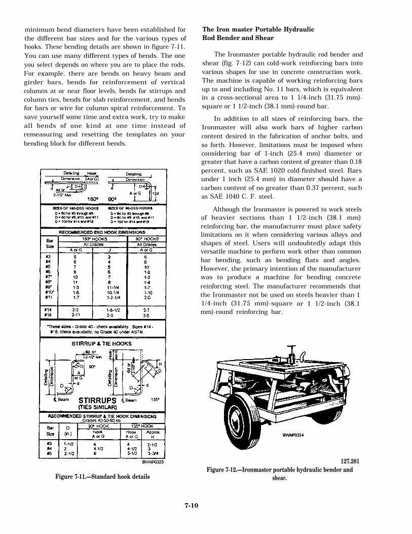
minimum bend diameters have been established forthe different bar sizes and for the various types ofhooks. These bending details are shown in figure 7-11.You can use many different types of bends. The oneyou select depends on where you are to place the rods.For example, there are bends on heavy beam andgirder bars, bends for reinforcement of verticalcolumns at or near floor levels, bends for stirrups andcolumn ties, bends for slab reinforcement, and bendsfor bars or wire for column spiral reinforcement. Tosave yourself some time and extra work, try to makeall bends of one kind at one time instead ofremeasuring and resetting the templates on yourbending block for different bends.
Figure 7-11.—Standard hook details
The Iron master Portable Hydraulic
Rod Bender and Shear
The Ironmaster portable hydraulic rod bender andshear (fig. 7-12) can cold-work reinforcing bars intovarious shapes for use in concrete construction work.The machine is capable of working reinforcing barsup to and including No. 11 bars, which is equivalentin a cross-sectional area to 1 1/4-inch (31.75 mm)-square or 1 1/2-inch (38.1 mm)-round bar.In addition to all sizes of reinforcing bars, theIronmaster will also work bars of higher carboncontent desired in the fabrication of anchor bolts, andso forth. However, limitations must be imposed whenconsidering bar of 1-inch (25.4 mm) diameter orgreater that have a carbon content of greater than 0.18percent, such as SAE 1020 cold-finished steel. Barsunder 1 inch (25.4 mm) in diameter should have acarbon content of no greater than 0.37 percent, suchas SAE 1040 C. F. steel.Although the Ironmaster is powered to work steelsof heavier sections than 1 1/2-inch (38.1 mm)reinforcing bar, the manufacturer must place safetylimitations on it when considering various alloys andshapes of steel. Users will undoubtedly adapt thisversatile machine to perform work other than commonbar bending, such as bending flats and angles.However, the primary intention of the manufacturerwas to produce a machine for bending concretereinforcing steel. The manufacturer recommends thatthe Ironmaster not be used on steels heavier than 11/4-inch (31.75 mm)-squaremm)-round reinforcing bar. or 1 1/2-inch (38.1
127.281
Figure 7-12.—Ironmaster portable hydraulic bender and
shear.
7-10

Standard Hook Bending
Standard hook bending ( f ig . 7 -13) i saccomplished on the turntable section located on topof the machine. Before you start any bendingprocedure, the turntable must be at the STARTposition as shown in figure 7-14. As an example,when you desire to bend a 180-degree hook in apieceof No. 11 reinforcing bar, setup the machine as shown,using the following: bending cleat with cleat slide anddrive pin, main center pin, and No. 11 radius roll. Asa safeguard, the radius rolls have been designed to
127.382
Figure 7-13.—Ironmaster bar-bending unit.
accept only the number of bars specified, suti as No.7 roll for No. 7 bar (fig. 7-15).1. Plain the rebar between the cleat slide uprightand the radius roll, which is placed over the center pin,
127.284
Figure 7-15.—Radius rolls for bending rebar on anIronmaster.
127.283
Figure 7-14.—ExampIe of bending a 180-degree hook with No. 11 rebar.
7-11

with the end of the rebar protruding a sufficient distancefor the cleat slide to be upright to engage it where youwant the bend to commence.2. Move the cleat slide to contact the rebar andtighten the locking screws.3. Move the positioner slide bar until the rollercontacts the rebar and tightens the T handle.4. Set the desired angle ‘of bend on the graduatedcontrol rod which is under the right side of the workingtable. This is done by placing the trigger pin of the rearadjustable stop (toward the rear of the machine) in thehole corresponding to the angle of bend, in this case,180 degrees. This rod is graduated from 5 degrees to190 degrees at 5-degree intervals.NOTE: ENSURE THE FRONT ADJUSTABLESTOP TRIGGER PIN IS IN THE “O’ HOLE, so theturntable will return to and stop in the START positionwhen retracted after the bend.5. Advance the engine throttle to operating speed,and move either the rear bending control lever or slidebending control lever to the bend position. This actuatesthe bend cylinder. The lever will stay in the bendingposition until the bend is completed, the rack movementdisengaging the cylinder, and the levers returning toneutral automatically.6. To remove the rebar from the machine after thebend is completed, apply light intermittent reversepressure to the lever until the bar releases from theradius roll. After removal of the hook from the machine,move the lever to the position shown on “retract” toreturn the turntable to the START position.
Multiple Bending
Multiple bending is accomplished the same wayas standard hook bending for bars up to No. 8 simplyby placing the bars in the machine one on top of theother.Table 7-5 shows the bars that may be bent by theIronmaster and the number of bars it will bend in oneoperation.On the side of the machine next to the shear is theshearing support (fig. 7-16). This support holds thebars square between the shear blades and preventsthem from “kicking up” during shearing. The upperjaw of the shearing support is adjustable. For barsthree-fourths inch and smaller, place this jaw in theLOWER position. For larger bars, use the UPPERposition. NEVER SHEAR WITHOUT USING THISSUPPORT.To operate, insert the bar to be cut to the farthestpoint possible toward the inside of the blades (fig.7-15), making sure that the blades are in the fullyOPEN or RETRACT position. With light downwardpressure on the shear control lever, hold the bar in thisposition until the shear grips. Continue applyingpressure downward to the full limit of the lever untilthe bar is sheared To retract the shear, pull the leverup.The same-size bar that can be bent can be shearedMultiple shearing, however, can be accomplished onlyon bars of less than 0.44-square-inch area. Whenshearing more than one bar at a time, always place thebars side by side in the shear, as shearing with barspiled on top of each other may cause blade failure.
Table 7-5.—Single Operation Multibending
Bar # Bar Size in Inches Number of Bars that can be
Bent in One Operation
3 3/8rd 64 1/2rd 45 5/8rd 36 3/4rd 37 7/8rd 28 1 rd 29 1 rd 1
10 1 1/8 sq 111 1 1/4 sq 1
7-12

127.285
Figure 7-16.—Ironmaster bar-cutting unit.
Table 7-6 shows the number of bars that can be shearedat one time.The care and maintenance of the Ironmasterportable hydraulic rod bender and shear consistprimarily of lubrication and cleaning. There are greasefittings on the machine. Keep these points welllubricated with a good grade of grease, but do notoverlubricate, as the surplus grease will collect dirtand rust scale from the rebars. When greasing theshear pin, work the shear arm up and down until greaseappears between the arm and the side ears. When usingthe stirrup bending attachment, keep the center pinclean and well lubricated.Rust scale from the rebar will accumulate in theholes in the turntable and worktable and in the serrationsin the bending cleat and roller slide. Keep these cleanedout, particular] y when changing over to or from thestirrup bending attachment or changing a center pin bymeans of a solvent-soaked rag or brush. Keep theworktable as clean as possible to minimize the amountof rust scale dropping through to the rack and gear.
PLACING AND TYING
REINFORCING STEEL
Before you place reinforcingform oiling should be completed. steel in forms, allOil on reinforcing
bars should be avoided because it reduces the bondbetween the bars and the concrete. Use a piece ofburlap to remove rust, mill scale, grease, mud, or otherforeign matter from the bars. A light film of rust ormill scale is not objectionable.Bars are marked to show where they will fit. Youmay work according to either one of the twomost-used systems for marking bars; however, thesystem you use should agree with the markingsystem which appears on the engineering orassembly drawings. The two marking systems usedare as follows:1. All bars in one type of member are given themark of that member. This system is used for columnbars, beam bars, footing bars, and so on.2. The bars are marked in greater detail. Thesemarks show exactly where the bar is to be placed. Inaddition to the type member (that is, beam (B), wall(W), column (C), and so on), the marks show the flooron which the bars are to be placed and the size andindividual number of each particular bar. Instead ofshowing the bar size by its diameter measurement, themark shows the bar size in code by eighths. Theexamples shown below show the second type ofmarking system.
2B805 2 = second floorB = beam member8 = 8/8- or 1 -inch (2.5 cm)-square bar05 = part of the second floor plan designatedby the number 5
2B0605 2 = second floorB = beam member06 = 6/8- or 3/4-inch (1.9 cm)-round bar05 = part of second floor plan designatedby the number 5
Tie wire is used to hold rebar in place to ensurethat when concrete is placed the bars do not shift outof position. Sixteen gauge wire is used to tieTable 7-6.—Multishearing
Bar Size Quantity
3,4 ,5 ,6 47 38 2
9, 10, 11 1
7-13

reinforcing bars. About 12 pounds (5.4 kg) of wire isrequired to tie an average ton (0.9 tome) of bars.NOTE: Tie wire adds nothing to the strength ofthe steel.A number of different types of ties can be usedwith reinforcing bars; some are more effective thanothers. Figure 7-17 shows six types of ties that areidentified below according to the letters of thealphabet used to show individual ties.A. SNAP TIE or SIMPLE TIE. The wire is simplywrapped once around the two crossing bars in adiagonal manner with the two ends on top. These aretwisted together with a pair of sidecutters until they arevery tight against the bars. Then the loose ends of thewire are cut off. This tie is used mostly on floor slabs.B. WALL TIE. This tie is made by going about 11/2 times around the vertical bar, then diagonallyaround the intersection, twisting the two ends togetheruntil the connection is tight, but without breaking thetie wire, then cutting off the excess. The wall tie is usedon light vertical mats of steel.C. DOUBLE-STRAND SINGLE TIE. This tie is avariation of the simple tie. It is especially favored forheavy workD. SADDLE TIE. The wires pass halfway aroundone of the ban on either side of the crossing bar and arebrought squarely or diagonally around the crossing barwith the ends twisted together and cut off. This tie isused on special locations, such as on walls.E. SADDLE TIE WITH TWIST. This tie is avariation of the saddle tie. The tie wire is carriedcompletely around one of the bars, then squarely acrossand halfway around the other, either side of the crossingbars, and finally brought together and twisted eithersquarely or diagonally across. The saddle tie with twistis used for heavy mats that are to be lifted by a crane.F. CROSS TIE or FIGURE-EIGHT TIE. This typeof tie has the advantage of causing little or no twist inthe bars.The proper location for the reinforcing bars isusually given on drawings (table 7-7). In order for thestructure to withstand the loads it must carry, place thesteel in the position shown. Secure the bars in positionin such a way that concrete-placing operations will notmove them. This can be accomplished by the use ofthe reinforcing bar supports shown in figures 7-18,7-19, and 7-20.
127.80
Figure 7-17.—Six types of ties.
45.480
Figure 7-18.—Reinforcement bar accessories.
The proper coverage of bars in the concrete is veryimportant to protect the bars from fire hazards,possibility of corrosion, and exposure to weather.When not specified, minimum standards given belowand in figure 7-21 should be observed.FOOTINGS-3 inches at the sides where concreteis cast against the earth and on the bottoms of footingsor other principal structural members where concreteis deposited on the ground.
7-14

127.83
Figure 7-19.—Precast concrete block used for rebar support.
WALLS-2 inches for bars larger than No. 5,where concrete surfaces, after removal of forms,would be exposed to the weather or be in contact withthe ground; 1 1/2 inches for No. 5 bars and smaller;3/4 inch from the faces of all walls not exposeddirectly to the ground or the weather.COLUMNS—1 1/2 inches over spirals and ties.BEAMS AND GIRDERS—1 1/2 inches to thenearest bars on the top, bottom, and sides.JOISTS AND SLABS—3/4 inch on the top,bottom, and sides of joists and on the top and thebottom of slabs where concrete surfaces are notexposed directly to the ground or the weather.NOTE: All measurements are from the outside ofthe bar to the face of the concrete, NOT from the mainsteel, unless otherwise specified.Footings and other principal structural membersthat are against the ground should have at least 3
Figure 7-20.—Rebar hung in place.
inches (76.2 mm) of concrete between the
127.85
steel andthe ground. If the concrete surface is to be in contactwith the ground or exposed to the weather afterremoval of the forms, the protective covering ofconcrete over the steel should be 2 inches (50.8 mm).It maybe reduced to 1 1/2inches (38.1 mm) for beamsand columns and 3/4 inch (19.5 mm) for slabs andinterior wall surfaces, but it should be 2 inches(50.8 mm) for all exterior wall surfaces. Thismeasurement is taken from the main rebar, not thestirrups or the ties.NOTE: Where splices in reinforcing steel are notdimensioned on the drawings, the bars should belapped not less than 30 times the bar diameter nor lessthan 12 inches (table 7-7). The stress in a tension bar
Table 7-7.—Length of Lap Splices in Reinforcing Steel
INCHES OF LAP CORRESPONDING TO NUMBER OF BAR DIAMETERS*
Number Size of Bars
of#3 #4 #5 #6 #7 #8 #9 #10 #11 #14 #18
Diameters
30 12 15 19 23 27 30 34 39 43 51 6832 12 16 20 24 28 32 36 41 45 55 7334 13 17 22 26 30 34 39 44 48 58 7736 14 18 23 27 32 36 41 46 51 61 8238 15 19 24 29 34 38 43 49 54 65 8640 15 20 25 30 35 40 46 51 57 68 91Minimum lap equals 12 inches!*Figured to the next larger whole inch
7-15

127.286
Figure 7-21.—Minimum coverage of rebar in concrete.
can be transmitted through the concrete and intoanother adjoining bar by a lap splice of proper length.To lap-weld wire fabric/wire mesh, you can use anumber of methods, two of which are the end lap andthe side lap. In the end lap method, the wire mesh islapped by overlapping one full mesh, measured fromthe ends of the longitudinal wires in one piece to theends of the longitudinal wires in the adjacent piece,and then tying the two pieces at 1-foot 6-inch (45.0cm) centers with a snap tie. In the side lap method, thetwo longitudinal side wires are placed one alongsideand overlapping the other and then are tied with a snaptie every 3 feet (.9 m).Reinforcing bars are in tension and thereforeshould never be bent around an inside corner beams.They can pull straight through the concrete cover.Instead, they should overlap and extend to the far facefor anchorage with 180-degree hooks and properconcrete coverage (fig. 7-23).The bars can also be spliced by metal arc weldingbut only if called for in the plans and specifications.For bars which are placed in a vertical position, a buttweld is preferred. The end of the bottom bar is cut
127.85
Figure 7-22.—Bars spliced by lapping.
145.66X
Figure 7-23.—Correct and Incorrect placement ofreinforcement for an inside corner.
square, and the end of the top bar resting on it is cutin a bevel fashion, thus permitting a butt weld. For barswhich will bear a load in a horizontal position, a filletweld is preferred. Usually, the two bars are placed endto end (rather than overlapping), and pieces of flat bar(or angle iron) are placed on either side. Fillet weldsare then made where the metals join. The welds are
7-16
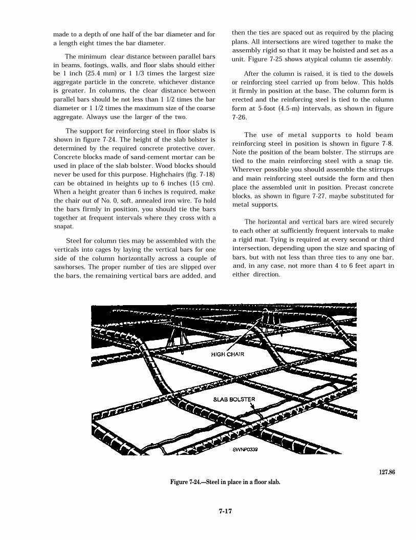
made to a depth of one half of the bar diameter and fora length eight times the bar diameter.The minimum clear distance between parallel barsin beams, footings, walls, and floor slabs should eitherbe 1 inch (25.4 mm) or 1 1/3 times the largest sizeaggregate particle in the concrete, whichever distanceis greater. In columns, the clear distance betweenparallel bars should be not less than 1 1/2 times the bardiameter or 1 1/2 times the maximum size of the coarseaggregate. Always use the larger of the two.The support for reinforcing steel in floor slabs isshown in figure 7-24. The height of the slab bolster isdetermined by the required concrete protective cover.Concrete blocks made of sand-cement mortar can beused in place of the slab bolster. Wood blocks shouldnever be used for this purpose. Highchairs (fig. 7-18)can be obtained in heights up to 6 inches (15 cm).When a height greater than 6 inches is required, makethe chair out of No. 0, soft, annealed iron wire. To holdthe bars firmly in position, you should tie the barstogether at frequent intervals where they cross with asnapat.Steel for column ties may be assembled with theverticals into cages by laying the vertical bars for oneside of the column horizontally across a couple ofsawhorses. The proper number of ties are slipped overthe bars, the remaining vertical bars are added, and
then the ties are spaced out as required by the placingplans. All intersections are wired together to make theassembly rigid so that it may be hoisted and set as aunit. Figure 7-25 shows atypical column tie assembly.After the column is raised, it is tied to the dowelsor reinforcing steel carried up from below. This holdsit firmly in position at the base. The column form iserected and the reinforcing steel is tied to the columnform at 5-foot (4.5-m) intervals, as shown in figure7-26.The use of metal supports to hold beamreinforcing steel in position is shown in figure 7-8.Note the position of the beam bolster. The stirrups aretied to the main reinforcing steel with a snap tie.Wherever possible you should assemble the stirrupsand main reinforcing steel outside the form and thenplace the assembled unit in position. Precast concreteblocks, as shown in figure 7-27, maybe substituted formetal supports.The horizontal and vertical bars are wired securelyto each other at sufficiently frequent intervals to makea rigid mat. Tying is required at every second or thirdintersection, depending upon the size and spacing ofbars, but with not less than three ties to any one bar,and, in any case, not more than 4 to 6 feet apart ineither direction.
127.86
Figure 7-24.—Steel in place in a floor slab.
7-17

Figure 7-25.—Column assembly.
127.87
Figure 7-26.—Method of holding column steel in plain informwork.
127.89
Figure 7-27.—Steel in place in a footing.
45.282B
127.88Figure 7-28.—Steel in place on a wall form
Steel in place in a wall is shown in figure 7-28.The wood block is removed when the form has beenfilled up to the level of the block For high walls, tiesin between the top and bottom should be used.Steel is placed in footings very much as it is placedin floor slabs. Stones, rather than steel supports, maybe used to support the steel at the proper distanceabove the subgrade. Steel mats in small footings aregenerally preassembled and placed after the formshave been set. A typical arrangement is shown infigure 7-27. Steel mats in large footings areconstructed in place.
7-18