steels explained
DESCRIPTION
List of commonly used steels with descriptions and typical heat treatment.TRANSCRIPT
Part two
Steel classification
Lucchini RS Steel Mill.
2 Part two • Steel classificationCo
mpa
riso
n ta
bles
Lucefin EUROPA ITALIA CINA GERMANIA FRANCIA UK RUSSIA USAGroup AISI
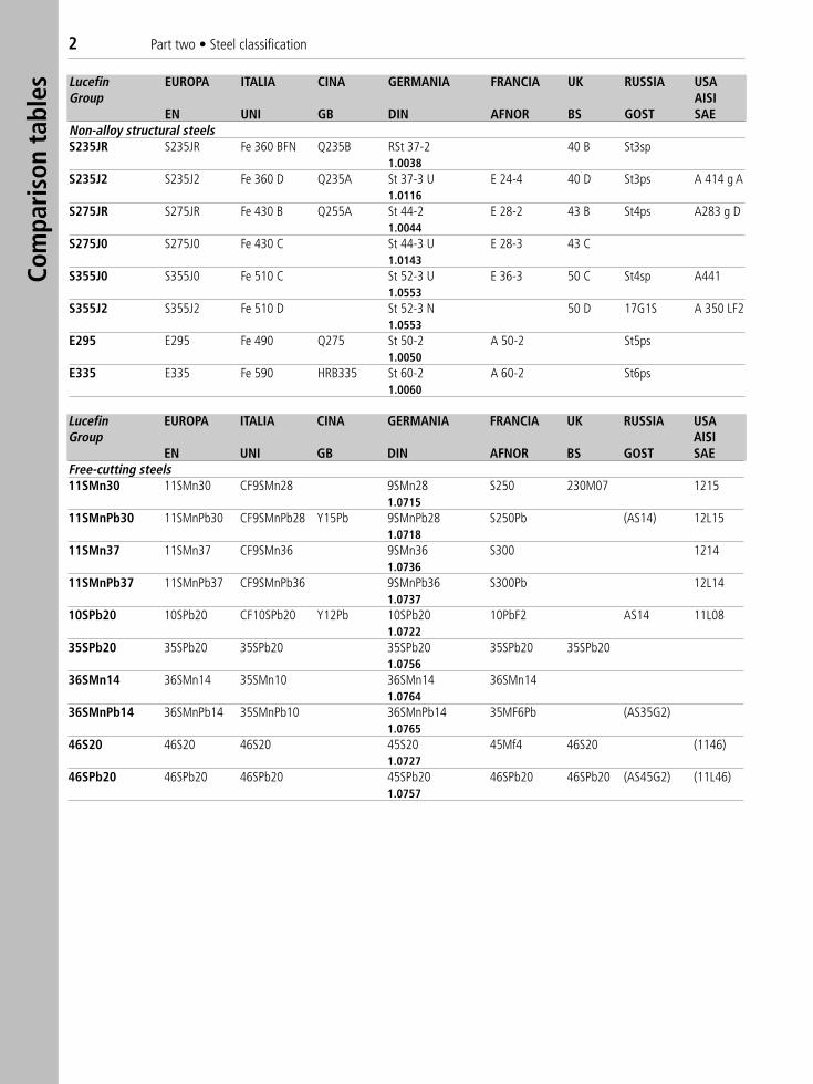
EN UNI GB DIN AFNOR BS GOST SAEFree-cutting steels11SMn30 11SMn30 CF9SMn28 9SMn28 S250 230M07 1215
1.071511SMnPb30 11SMnPb30 CF9SMnPb28 Y15Pb 9SMnPb28 S250Pb (AS14) 12L15
1.071811SMn37 11SMn37 CF9SMn36 9SMn36 S300 1214
1.073611SMnPb37 11SMnPb37 CF9SMnPb36 9SMnPb36 S300Pb 12L14
1.073710SPb20 10SPb20 CF10SPb20 Y12Pb 10SPb20 10PbF2 AS14 11L08
1.072235SPb20 35SPb20 35SPb20 35SPb20 35SPb20 35SPb20
1.075636SMn14 36SMn14 35SMn10 36SMn14 36SMn14
1.076436SMnPb14 36SMnPb14 35SMnPb10 36SMnPb14 35MF6Pb (AS35G2)
1.076546S20 46S20 46S20 45S20 45Mf4 46S20 (1146)
1.072746SPb20 46SPb20 46SPb20 45SPb20 46SPb20 46SPb20 (AS45G2) (11L46)
1.0757
Lucefin EUROPA ITALIA CINA GERMANIA FRANCIA UK RUSSIA USAGroup AISI
EN UNI GB DIN AFNOR BS GOST SAENon-alloy structural steelsS235JR S235JR Fe 360 BFN Q235B RSt 37-2 40 B St3sp
1.0038S235J2 S235J2 Fe 360 D Q235A St 37-3 U E 24-4 40 D St3ps A 414 g A
1.0116S275JR S275JR Fe 430 B Q255A St 44-2 E 28-2 43 B St4ps A283 g D
1.0044S275J0 S275J0 Fe 430 C St 44-3 U E 28-3 43 C
1.0143S355J0 S355J0 Fe 510 C St 52-3 U E 36-3 50 C St4sp A441
1.0553S355J2 S355J2 Fe 510 D St 52-3 N 50 D 17G1S A 350 LF2
1.0553E295 E295 Fe 490 Q275 St 50-2 A 50-2 St5ps
1.0050E335 E335 Fe 590 HRB335 St 60-2 A 60-2 St6ps
1.0060
Part two • Steel classification 3
Lucefin EUROPA ITALIA CINA GERMANIA FRANCIA UK RUSSIA USAGroup AISI
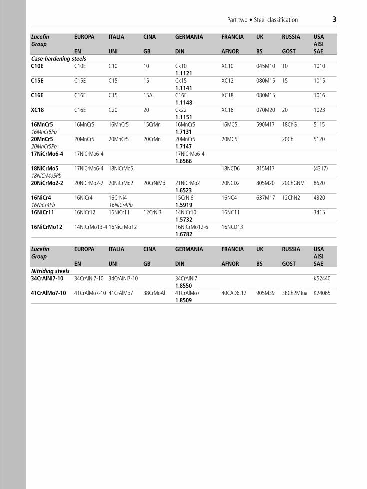
EN UNI GB DIN AFNOR BS GOST SAECase-hardening steelsC10E C10E C10 10 Ck10 XC10 045M10 10 1010
1.1121C15E C15E C15 15 Ck15 XC12 080M15 15 1015
1.1141C16E C16E C15 15AL C16E XC18 080M15 1016
1.1148XC18 C16E C20 20 Ck22 XC16 070M20 20 1023
1.115116MnCr5 16MnCr5 16MnCr5 15CrMn 16MnCr5 16MC5 590M17 18ChG 511516MnCr5Pb 1.713120MnCr5 20MnCr5 20MnCr5 20CrMn 20MnCr5 20MC5 20Ch 512020MnCr5Pb 1.714717NiCrMo6-4 17NiCrMo6-4 17NiCrMo6-4
1.656618NiCrMo5 17NiCrMo6-4 18NiCrMo5 18NCD6 815M17 (4317)18NiCrMo5Pb20NiCrMo2-2 20NiCrMo2-2 20NiCrMo2 20CrNiMo 21NiCrMo2 20NCD2 805M20 20ChGNM 8620
1.652316NiCr4 16NiCr4 16CrNi4 15CrNi6 16NC4 637M17 12ChN2 432016NiCr4Pb 16NiCr4Pb 1.591916NiCr11 16NiCr12 16NiCr11 12CrNi3 14NiCr10 16NC11 3415
1.573216NiCrMo12 14NiCrMo13-4 16NiCrMo12 16NiCrMo12-6 16NCD13
1.6782
Lucefin EUROPA ITALIA CINA GERMANIA FRANCIA UK RUSSIA USAGroup AISI
EN UNI GB DIN AFNOR BS GOST SAENitriding steels34CrAlNi7-10 34CrAlNi7-10 34CrAlNi7-10 34CrAlNi7 K52440
1.855041CrAlMo7-10 41CrAlMo7-10 41CrAlMo7 38CrMoAl 41CrAlMo7 40CAD6.12 905M39 38Ch2MJua K24065
1.8509
4 Part two • Steel classification
Lucefin EUROPA ITALIA CINA GERMANIA FRANCIA UK RUSSIA USAGroup AISI
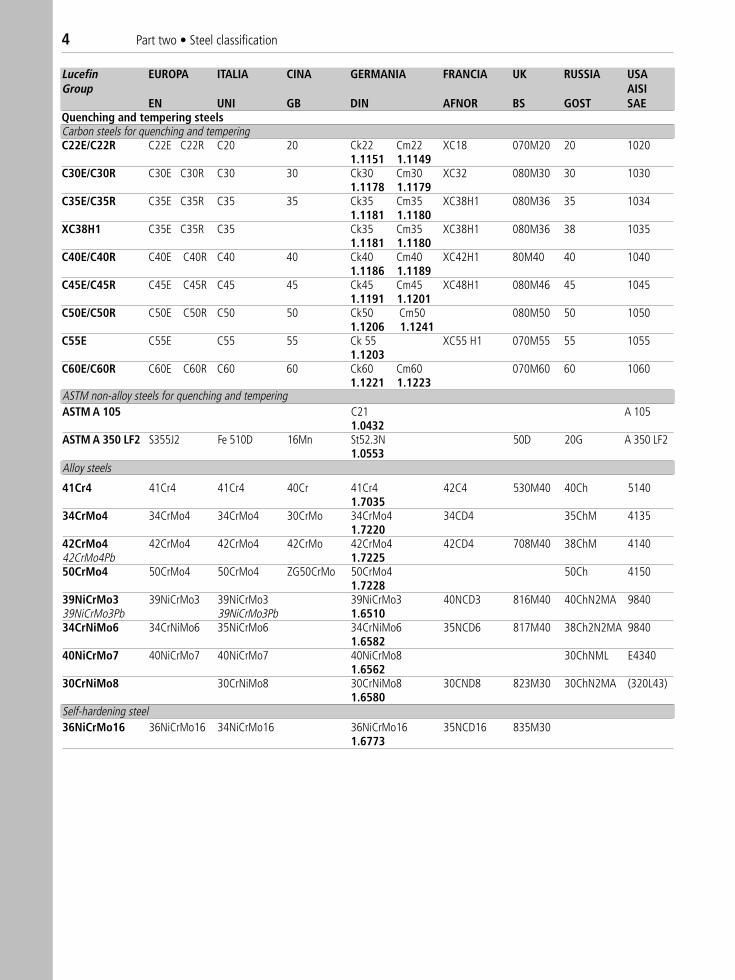
EN UNI GB DIN AFNOR BS GOST SAEQuenching and tempering steelsCarbon steels for quenching and temperingC22E/C22R C22E C22R C20 20 Ck22 Cm22 XC18 070M20 20 1020
1.1151 1.1149C30E/C30R C30E C30R C30 30 Ck30 Cm30 XC32 080M30 30 1030
1.1178 1.1179C35E/C35R C35E C35R C35 35 Ck35 Cm35 XC38H1 080M36 35 1034
1.1181 1.1180XC38H1 C35E C35R C35 Ck35 Cm35 XC38H1 080M36 38 1035
1.1181 1.1180C40E/C40R C40E C40R C40 40 Ck40 Cm40 XC42H1 80M40 40 1040
1.1186 1.1189C45E/C45R C45E C45R C45 45 Ck45 Cm45 XC48H1 080M46 45 1045
1.1191 1.1201C50E/C50R C50E C50R C50 50 Ck50 Cm50 080M50 50 1050
1.1206 1.1241C55E C55E C55 55 Ck 55 XC55 H1 070M55 55 1055
1.1203C60E/C60R C60E C60R C60 60 Ck60 Cm60 070M60 60 1060
1.1221 1.1223
Alloy steels
41Cr4 41Cr4 41Cr4 40Cr 41Cr4 42C4 530M40 40Ch 51401.7035
34CrMo4 34CrMo4 34CrMo4 30CrMo 34CrMo4 34CD4 35ChM 41351.7220
42CrMo4 42CrMo4 42CrMo4 42CrMo 42CrMo4 42CD4 708M40 38ChM 414042CrMo4Pb 1.722550CrMo4 50CrMo4 50CrMo4 ZG50CrMo 50CrMo4 50Ch 4150
1.722839NiCrMo3 39NiCrMo3 39NiCrMo3 39NiCrMo3 40NCD3 816M40 40ChN2MA 984039NiCrMo3Pb 39NiCrMo3Pb 1.651034CrNiMo6 34CrNiMo6 35NiCrMo6 34CrNiMo6 35NCD6 817M40 38Ch2N2MA 9840
1.658240NiCrMo7 40NiCrMo7 40NiCrMo7 40NiCrMo8 30ChNML E4340
1.656230CrNiMo8 30CrNiMo8 30CrNiMo8 30CND8 823M30 30ChN2MA (320L43)
1.6580Self-hardening steel36NiCrMo16 36NiCrMo16 34NiCrMo16 36NiCrMo16 35NCD16 835M30
1.6773
ASTM non-alloy steels for quenching and tempering ASTM A 105 C21 A 105
1.0432ASTM A 350 LF2 S355J2 Fe 510D 16Mn St52.3N 50D 20G A 350 LF2
1.0553
Part two • Steel classification 5
Lucefin EUROPA ITALIA CINA GERMANIA FRANCIA UK RUSSIA USAGroup AISI
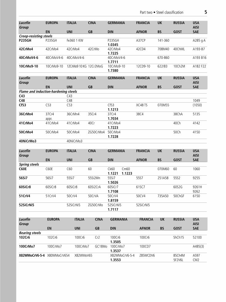
EN UNI GB DIN AFNOR BS GOST SAECreep-resisting steelsP235GH P235GH Fe360 1 KW P235GH A37CP 141-360 A285 g A
1.034542CrMo4 42CrMo4 42CrMo4 42CrMo 42CrMo4 42CD4 708M40 40ChML A193-B7
1.722540CrMoV4-6 40CrMoV4-6 40CrMoV4-6 40CrMoV4-6 670-860 A193 B16
1.771110CrMo9-10 10CrMo9-10 12CrMo9 10 KG 12Cr2MoG 10CrMo9-10 12CD9-10 622/B3 10Ch2M A182 F22
1.7380
Lucefin EUROPA ITALIA CINA GERMANIA FRANCIA UK RUSSIA USAGroup AISI
EN UNI GB DIN AFNOR BS GOST SAEFlame and induction-hardening steelsC43 C43C48 C48 1049Cf53 C53 C53 Cf53 XC48 TS 070M55 (1050)
1.121336CrMn4 37Cr4 36CrMn4 35Cr4 37Cr4 38C4 38ChA 5135
appr. 1.703441CrMo4 41CrMo4 41CrMo4 40Cr 41CrMo4 40Ch 4142
1.722350CrMo4 50CrMo4 50CrMo4 ZG50CrMo4 50CrMo4 50Ch 4150
1.722840NiCrMo3 40NiCrMo3
Lucefin EUROPA ITALIA CINA GERMANIA FRANCIA UK RUSSIA USAGroup AISI
EN UNI GB DIN AFNOR BS GOST SAESpring steelsC60E C60E C60 60 Ck60 Cm60 070M60 60 1060
1.1221 1.122356Si7 56Si7 55Si7 55Si2Mn 55Si7 55S7 251A58 55S2 9255
1.502660SiCr8 60SiCr8 60SiCr8 60Si2CrA 60SiCr7 61SC7 60S2G 9261H
1.7108 926251CrV4 51CrV4 50CrV4 50CrVA 50CrV4 50CV4 735A50 50ChGF 6150
1.815952SiCrNi5 52SiCrNi5 ZG50CrMo 52SiCrNi5 52SiCrNi5
1.7117
Lucefin EUROPA ITALIA CINA GERMANIA FRANCIA UK RUSSIA USAGroup AISI
EN UNI GB DIN AFNOR BS GOST SAEBearing steels102Cr6 102Cr6 100Cr6 Cr2 100Cr6 100Cr6 ShCh15 52100
1.3505100CrMo7 100CrMo7 100CrMo7 GC18Mo 100CrMo7 100CD7 A485(3)
1.3537X82WMoCrV6-5-4 X80WMoCrV654 X82WMoV65 X82WMoCrV6-5-4 Z85WCDV6 85Ch4M A597
1.3553 5F2V6L CM2
6 Part two • Steel classification
Lucefin EUROPA ITALIA CINA GERMANIA FRANCIA UK RUSSIA USAGroup AISI
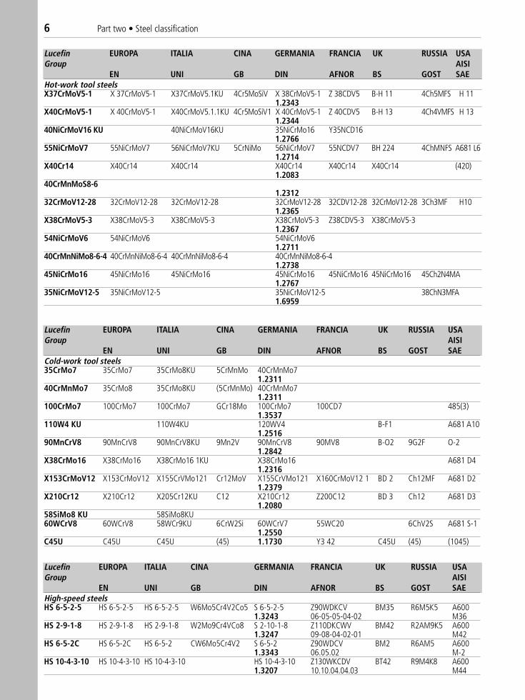
EN UNI GB DIN AFNOR BS GOST SAEHot-work tool steelsX37CrMoV5-1 X 37CrMoV5-1 X37CrMoV5.1KU 4Cr5MoSiV X 38CrMoV5-1 Z 38CDV5 B-H 11 4Ch5MFS H 11
1.2343X40CrMoV5-1 X 40CrMoV5-1 X40CrMoV5.1.1KU 4Cr5MoSiV1 X 40CrMoV5-1 Z 40CDV5 B-H 13 4Ch4VMFS H 13
1.234440NiCrMoV16 KU 40NiCrMoV16KU 35NiCrMo16 Y35NCD16
1.276655NiCrMoV7 55NiCrMoV7 56NiCrMoV7KU 5CrNiMo 56NiCrMoV7 55NCDV7 BH 224 4ChMNFS A681 L6
1.2714X40Cr14 X40Cr14 X40Cr14 X40Cr14 X40Cr14 X40Cr14 (420)
1.208340CrMnMoS8-6
1.231232CrMoV12-28 32CrMoV12-28 32CrMoV12-28 32CrMoV12-28 32CDV12-28 32CrMoV12-28 3Ch3MF H10
1.2365X38CrMoV5-3 X38CrMoV5-3 X38CrMoV5-3 X38CrMoV5-3 Z38CDV5-3 X38CrMoV5-3
1.236754NiCrMoV6 54NiCrMoV6 54NiCrMoV6
1.271140CrMnNiMo8-6-4 40CrMnNiMo8-6-4 40CrMnNiMo8-6-4 40CrMnNiMo8-6-4
1.273845NiCrMo16 45NiCrMo16 45NiCrMo16 45NiCrMo16 45NiCrMo16 45NiCrMo16 45Ch2N4MA
1.276735NiCrMoV12-5 35NiCrMoV12-5 35NiCrMoV12-5 38ChN3MFA
1.6959
Lucefin EUROPA ITALIA CINA GERMANIA FRANCIA UK RUSSIA USAGroup AISI
EN UNI GB DIN AFNOR BS GOST SAECold-work tool steels35CrMo7 35CrMo7 35CrMo8KU 5CrMnMo 40CrMnMo7
1.231140CrMnMo7 35CrMo8 35CrMo8KU (5CrMnMo) 40CrMnMo7
1.2311100CrMo7 100CrMo7 100CrMo7 GCr18Mo 100CrMo7 100CD7 485(3)
1.3537110W4 KU 110W4KU 120WV4 B-F1 A681 A10
1.251690MnCrV8 90MnCrV8 90MnCrV8KU 9Mn2V 90MnCrV8 90MV8 B-O2 9G2F O-2
1.2842X38CrMo16 X38CrMo16 X38CrMo16 1KU X38CrMo16 A681 D4
1.2316X153CrMoV12 X153CrMoV12 X155CrVMo121 Cr12MoV X155CrVMo121 X160CrMoV12 1 BD 2 Ch12MF A681 D2
1.2379X210Cr12 X210Cr12 X205Cr12KU C12 X210Cr12 Z200C12 BD 3 Ch12 A681 D3
1.208058SiMo8 KU 58SiMo8KU60WCrV8 60WCrV8 58WCr9KU 6CrW2Si 60WCrV7 55WC20 6ChV2S A681 S-1
1.2550C45U C45U C45U (45) 1.1730 Y3 42 C45U (45) (1045)
Lucefin EUROPA ITALIA CINA GERMANIA FRANCIA UK RUSSIA USAGroup AISI
EN UNI GB DIN AFNOR BS GOST SAEHigh-speed steelsHS 6-5-2-5 HS 6-5-2-5 HS 6-5-2-5 W6Mo5Cr4V2Co5 S 6-5-2-5 Z90WDKCV BM35 R6M5K5 A600
1.3243 06-05-05-04-02 M36HS 2-9-1-8 HS 2-9-1-8 HS 2-9-1-8 W2Mo9Cr4VCo8 S 2-10-1-8 Z110DKCWV BM42 R2AM9K5 A600
1.3247 09-08-04-02-01 M42HS 6-5-2C HS 6-5-2C HS 6-5-2 CW6Mo5Cr4V2 S 6-5-2 Z90WDCV BM2 R6AM5 A600
1.3343 06.05.02 M-2HS 10-4-3-10 HS 10-4-3-10 HS 10-4-3-10 HS 10-4-3-10 Z130WKCDV BT42 R9M4K8 A600
1.3207 10.10.04.04.03 M44
Part two • Steel classification 7
Lucefin EUROPA ITALIA CINA GERMANIA FRANCIA UK RUSSIA USAGroup AISI
EN UNI GB DIN AFNOR BS GOST SAESteels for crome-platingS355J2 S355J2 Fe510D St52-3 N 50D 17G1S A350LF2
1.0553C45E C45E C45R C45 45 Ck45 Cm45 XC48H1 080M46 45 1045
1.1191 1.1201Cf53 C53 C53 Cf53 XC48 TS 070M55 1050
1.121320MnVS6 20MnV6 20MnV 20MnV6 A381
1.521742CrMo4 42CrMo4 42CrMo4 42CrMo 42CrMo4 42CD4 708M40 38ChM 4140
1.722539NiCrMo3 39NiCrMo3 39NiCrMo3 36CrNiMo4 40NCD3 816M40 40ChN2MA 9840
1.651150CrMo4 50CrMo4 50CrMo4 ZG50CrMo 50CrMo4 50Ch 4150
1.7228
Lucefin EUROPA ITALIA CINA GERMANIA FRANCIA UK RUSSIA USAGroup AISI
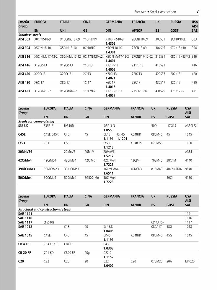
EN UNI GB DIN AFNOR BS GOST SAEStainless steelsAISI 303 X8CrNiS18-9 X10CrNiS18-09 Y1Cr18Ni9 X10CrNiS18-9 Z8CNF18-09 303S31 2Ch18N10E 303
1.4305AISI 304 X5CrNi18-10 X5CrNi18-10 0Cr18Ni9 X5CrNi18-10 Z5CN18-09 304S15 07Ch18N10 304
1.4301AISI 316 X5CrNiMo17-12-2 X5CrNiMo17-12 0Cr17Ni12Mo2 X5CrNiMo17-12-2 Z7CND17-12-02 316S31 08Ch17N13M2 316
1.4401AISI 416 X12CrS13 X12CrS13 Y1Cr13 X12CrS13 Z11CF13 416S21 416
1.4005AISI 420 X20Cr13 X20Cr13 2Cr13 X20Cr13 Z20C13 420S37 20Ch13 420
1.4021AISI 430 X6Cr17 X8Cr17 1Cr17 X6Cr17 Z8C17 430S17 12Ch17 430
1.4016AISI 431 X17CrNi16-2 X17CrNi16-2 1Cr17Ni2 X17CrNi16-2 Z15CN16-02 431S29 17Ch17N2 431
1.4057
Lucefin EUROPA ITALIA CINA GERMANIA FRANCIA UK RUSSIA USAGroup AISI
EN UNI GB DIN AFNOR BS GOST SAEStructural and constructional steelsSAE 1141 1141SAE 1116 1116SAE 1117 (15S10) (214A15) 1117SAE 1018 C18 20 St 45.8 080A17 18G 1018
1.0405SAE 1045 C45E C45 45 CK45 XC48H1 080M46 45G 1045
1.1191CB 4 FF CB4 FF KD CB4 FF C4 C
1.0303CB 20 FF C21 KD CB20 FF 20g C22 C
1.1152C20 C22 C20 20 C22 C20 070M20 20A M1020
1.0402
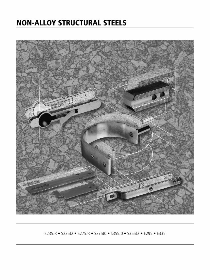
NON-ALLOY STRUCTURAL STEELS
S235JR • S235J2 • S275JR • S275J0 • S355J0 • S355J2 • E295 • E335
Part two • Non-alloy structural steels 9S2
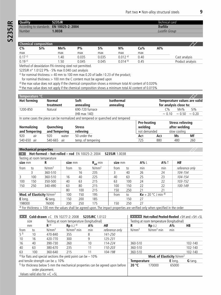
35JR Quality S235JR Technical card
According to standards EN 10025-2: 2004 TrafilixNumber 1.0038 Lucefin Group
Chemical compositionC% Si% Mn% P% S% N% Cu% Al%max max max max max max0.17 c) 1.40 0.035 0.035 0.012 a) 0.40 Cast analysis0.19 c) 1.50 0.045 0.045 0.014 b) 0.45 Product analysisMethod of deoxidation FN rimming steel not permitted.S235JR n° 1.0122 P% - S% max 0.040 cast analysisc) for nominal thickness > 40 mm to 100 mm max 0.20 of ladle / 0.23 of the product;
for nominal thickness > 100 mm the C content must be agreed upona) the max value does not apply if the chemical composition shows a minimum total Al content of 0.020% b) the max value does not apply if the chemical composition shows a minimum total Al content of 0.015%
Temperature °C Hot forming Normal Soft Isothermal Temperature values are valid
treatment annealing annealing for analysis close to:1200-850 Natural 690-720 furnace C% Mn% Si%
(HB max 140) ~ 0.10 ~ 0.50 ~ 0.20In some cases the piece can be normalized and tempered or quenched and tempered
Pre-heating Stress relievingNormalizing Quenching Stress welding after weldingand Tempering and Tempering relieving not demanded slow cooling920 air 920 water 50 under the Ac1 Ac3 Ms Mf540-650 air 540-665 air temp. of tempering 725 880 480 260
Mechanical propertiesHot-formed – hot-rolled – rod EN 10025-2: 2004 S235JR 1.0038
Testing at room temperaturesize mm R size mm ReH min size mm A% L A% T HB
from to N/mm2 from to N/mm2 from to min min reference only3 360-510 16 235 3 40 26 24 104-154
3 100 360-510 16 40 225 40 63 25 23 104-154100 150 350-500 40 63 215 63 100 24 22 103-152150 250 340-490 63 80 215 100 150 22 22 100-149
80 100 215 150 250 21 21Mod. of Elasticity N/mm2 100 150 195 from to Kv + 20 °C J min d)
E long. G tang. 150 200 185 150 27 198000 76000 200 250 175 150 250 27d) For thickness > 100 mm the values shall be agreed upon. The impact properties are verified only when specified in the order
Cold-drawn +C EN 10277-2: 2008 S235JRC 1.0122 Hot-rolled Peeled-Reeled +SH and +SH +SLsize Testing at room temperature (longitudinal) Testing at room temperature (longitudinal)mm R e) Rp 0.2 e) A% HB R Rp 0.2 A% HB
from to N/mm2 N/mm2 min min reference only N/mm2 N/mm2 min min5 f) 10 470-840 355 8 141-25010 16 420-770 300 9 125-23116 40 390-730 260 10 114-224 360-510 102-14040 63 380-670 235 11 110-203 360-510 102-14063 100 360-640 215 11 104-198 360-510 102-140e) for flats and special sections the yield point can be – 10% Mod. of Elasticity N/mm2
and tensile strength can be ± 10% Temperature E long. G tang.f) for thickness below 5 mm the mechanical properties can be agreed upon before 20 °C 170000 65000
order placement. Values valid also for +C +SL
10 Part two • Non-alloy structural steels
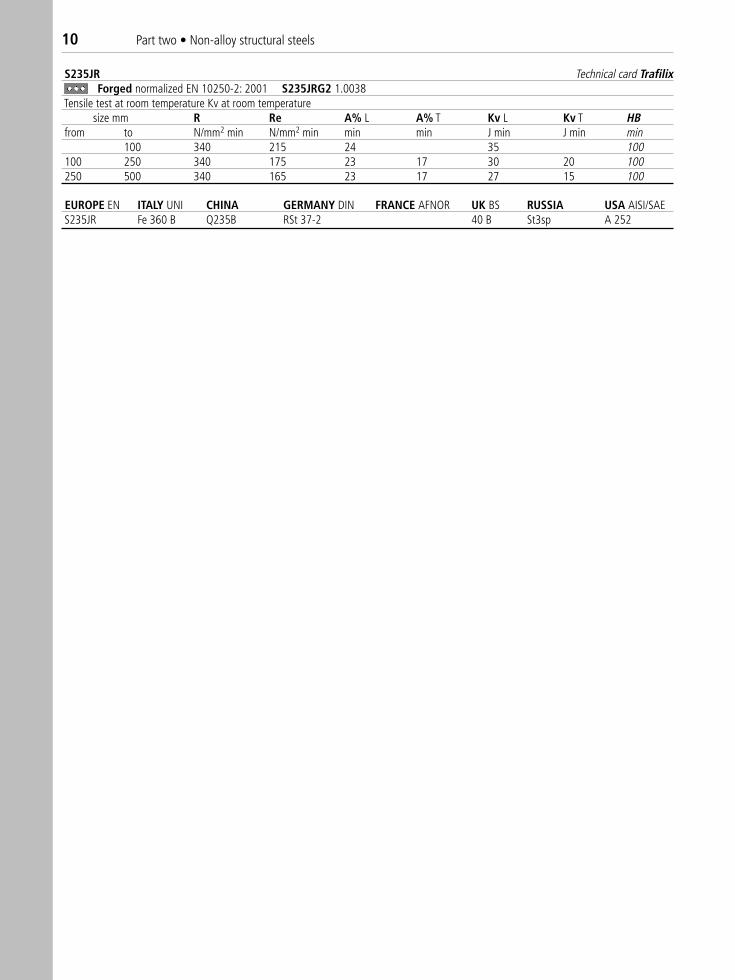
S235JR Technical card TrafilixForged normalized EN 10250-2: 2001 S235JRG2 1.0038 �
Tensile test at room temperature Kv at room temperaturesize mm R Re A% L A% T Kv L Kv T HB
from to N/mm2 min N/mm2 min min min J min J min min100 340 215 24 35 100
100 250 340 175 23 17 30 20 100250 500 340 165 23 17 27 15 100
EUROPE EN ITALY UNI CHINA GERMANY DIN FRANCE AFNOR UK BS RUSSIA USA AISI/SAE S235JR Fe 360 B Q235B RSt 37-2 40 B St3sp A 252
Part two • Non-alloy structural steels 11S2
35J2
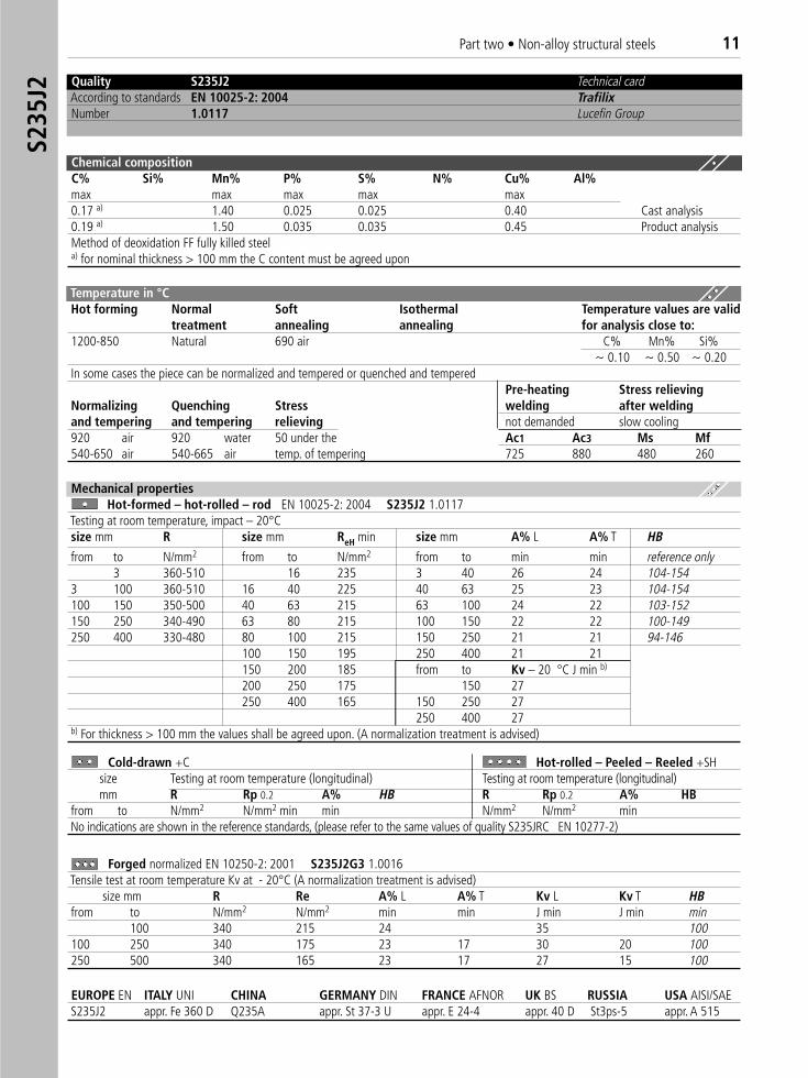
EUROPE EN ITALY UNI CHINA GERMANY DIN FRANCE AFNOR UK BS RUSSIA USA AISI/SAE S235J2 appr. Fe 360 D Q235A appr. St 37-3 U appr. E 24-4 appr. 40 D St3ps-5 appr. A 515
Quality S235J2 Technical cardAccording to standards EN 10025-2: 2004 TrafilixNumber 1.0117 Lucefin Group
Chemical compositionC% Si% Mn% P% S% N% Cu% Al%max max max max max0.17 a) 1.40 0.025 0.025 0.40 Cast analysis0.19 a) 1.50 0.035 0.035 0.45 Product analysisMethod of deoxidation FF fully killed steel a) for nominal thickness > 100 mm the C content must be agreed upon
Temperature in °CHot forming Normal Soft Isothermal Temperature values are valid
treatment annealing annealing for analysis close to:1200-850 Natural 690 air C% Mn% Si%
~ 0.10 ~ 0.50 ~ 0.20In some cases the piece can be normalized and tempered or quenched and tempered
Pre-heating Stress relievingNormalizing Quenching Stress welding after weldingand tempering and tempering relieving not demanded slow cooling920 air 920 water 50 under the Ac1 Ac3 Ms Mf540-650 air 540-665 air temp. of tempering 725 880 480 260
Mechanical propertiesHot-formed – hot-rolled – rod EN 10025-2: 2004 S235J2 1.0117
Testing at room temperature, impact – 20°Csize mm R size mm ReH min size mm A% L A% T HB
from to N/mm2 from to N/mm2 from to min min reference only3 360-510 16 235 3 40 26 24 104-154
3 100 360-510 16 40 225 40 63 25 23 104-154100 150 350-500 40 63 215 63 100 24 22 103-152150 250 340-490 63 80 215 100 150 22 22 100-149250 400 330-480 80 100 215 150 250 21 21 94-146
100 150 195 250 400 21 21150 200 185 from to Kv – 20 °C J min b)
200 250 175 150 27 250 400 165 150 250 27
250 400 27b) For thickness > 100 mm the values shall be agreed upon. (A normalization treatment is advised)
Cold-drawn +C Hot-rolled – Peeled – Reeled +SHsize Testing at room temperature (longitudinal) Testing at room temperature (longitudinal)mm R Rp 0.2 A% HB R Rp 0.2 A% HB
from to N/mm2 N/mm2 min min N/mm2 N/mm2 minNo indications are shown in the reference standards, (please refer to the same values of quality S235JRC EN 10277-2)
Forged normalized EN 10250-2: 2001 S235J2G3 1.0016Tensile test at room temperature Kv at - 20°C (A normalization treatment is advised)
size mm R Re A% L A% T Kv L Kv T HBfrom to N/mm2 N/mm2 min min J min J min min
100 340 215 24 35 100100 250 340 175 23 17 30 20 100250 500 340 165 23 17 27 15 100
12 Part two • Non-alloy structural steels
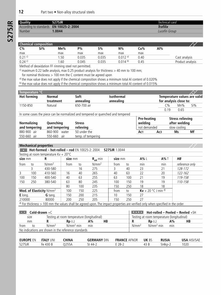
Quality S275JR Technical cardAccording to standards EN 10025-2: 2004 TrafilixNumber 1.0044 Lucefin Group
Temperature °CHot forming Normal Soft Isothermal Temperature values are valid
treatment annealing annealing for analysis close to:1150-850 Natural 650-700 air C% Mn% Si%
0.19 0.65In some cases the piece can be normalized and tempered or quenched and tempered
Pre-heating Stress relievingNormalizing Quenching Stress welding after weldingand tempering and tempering relieving not demanded slow cooling880-900 air 860-900 water 50 under the Ac1 Ac3 Ms Mf550-660 air 550-660 air temp. of tempering
Mechanical propertiesHot-formed – hot-rolled – rod EN 10025-2: 2004 S275JR 1.0044
Testing at room temperature Kv + 20°Csize mm R size mm ReH min size mm A% L A% T HB
from to N/mm2 from to N/mm2 from to min min reference only3 430-580 16 275 3 40 23 21 128-172
3 100 410-560 16 40 265 40 63 22 20 122-162100 150 400-540 40 63 255 63 100 21 19 119-158150 250 380-540 63 80 245 100 150 19 19 110-158
80 100 235 150 250 18 18Mod. of Elasticity N/mm2 100 150 225 from to Kv + 20 °C J min d)
E long. G tang. 150 200 215 10 150 27210000 80000 200 250 205 150 250 27d) For thickness > 100 mm the values shall be agreed upon. The impact properties are verified only when specified in the order
Cold-drawn +C Hot-rolled – Peeled – Reeled +SHsize Testing at room temperature (longitudinal) Testing at room temperature (longitudinal)mm R Rp 0.2 A% HB R Rp 0.2 A% HB
from to N/mm2 N/mm2 min min N/mm2 N/mm2 min minNo indications are shown in the reference standards
EUROPE EN ITALY UNI CHINA GERMANY DIN FRANCE AFNOR UK BS RUSIA USA AISI/SAES275JR Fe 430 B Q255A St 44-2 E 28-2 43 B St4kp-2 1020
S275
JR
Chemical compositionC% Si% Mn% P% S% N% Cu% Al%max max max max max max0.21 c) 1.50 0.035 0.035 0.012 a) 0.40 Cast analysis0.24 c) 1.60 0.045 0.035 0.014 b) 0.45 Product analysisMethod of deoxidation FF rimming steel not permitted.c) maximum 0.22 ladle analysis, max 0.25 product analysis for thickness > 40 mm to 100 mm;
for nominal thickness > 100 mm the C content must be agreed upona) the max value does not apply if the chemical composition shows a minimum total Al content of 0.020%b) the max value does not apply if the chemical composition shows a minimum total Al content of 0.015%

Part two • Non-alloy structural steels 13S2
75J0 Quality S275J0 Technical card
According to standards EN 10025-2: 2004 TrafilixNumber 1.0143 Lucefin Group
Chemical compositionC% Si% Mn% P% S% N% Cu% Al%max max max max max max0.18 c) 1.50 0.040 0.040 0.009 a) 0.40 Cast analysis0.21 c) 1.60 0.050 0.050 0.011 b) 0.45 Product analysisMethod of deoxidation FN rimming steel not permitted.c) max 0.20 ladle analysis, max 0,22 product analysis for thickness > 150 mm;
for nominal thickness > 100 mm the C content must be agreed upona) the max value does not apply if the chemical composition shows a minimum total Al content of 0.020%b) ithe max value does not apply if the chemical composition shows a minimum total Al content of 0.015%
Temperature °C Hot forming Normal Soft Isothermal Temperature values are valid
treatment annealing annealing for analysis close to:1200-850 Natural 690 airIn some cases the piece can be normalized and tempered or quenched and tempered
Pre-heating Stress relievingNormalizing Quenching Stress welding after weldingand tempering and tempering relieving not demanded slow cooling920 air 920 water 50 under the Ac1 Ac3 Ms Mf540-650 air 540-665 air temp. of tempering
Cold-drawn +C Hot-rolled – Peeled – Reeled +SHsize Testing at room temperature (longitudinal) Testing at room temperature (longitudinal)mm R Rp 0.2 A% HB R Rp 0.2 A% HB
from to N/mm2 N/mm2 min min N/mm2 N/mm2 min minNo indications are shown in the reference standards
EUROPE EN ITALY UNI CHINA GERMANY DIN FRANCE AFNOR UK BS RUSSIA USA AISI/SAE S275J0 Fe 430 C St 44-3 U E 28-3 43 C
Mechanical propertiesHot-formed – hot-rolled – rod EN 10025-2: 2004 S275J0 1.0143
Testing at room temperature Kv 0°Csize mm R size mm ReH min size mm A% L A% T HB
from to N/mm2 from to N/mm2 from to min min reference only3 430-580 16 275 3 40 23 21 128-172
3 100 410-560 16 40 265 40 63 22 20 122-162100 150 400-540 40 63 255 63 100 21 19 119-158150 250 380-540 63 80 245 100 150 19 19 110-158
80 100 235 150 250 18 18100 150 225 from to Kv 0 °C J min d)
150 200 215 10 150 27 200 250 205 150 250 27
d) For thickness > 100 mm the values shall be agreed upon. (A normalization treatment is advised)
14 Part two • Non-alloy structural steels
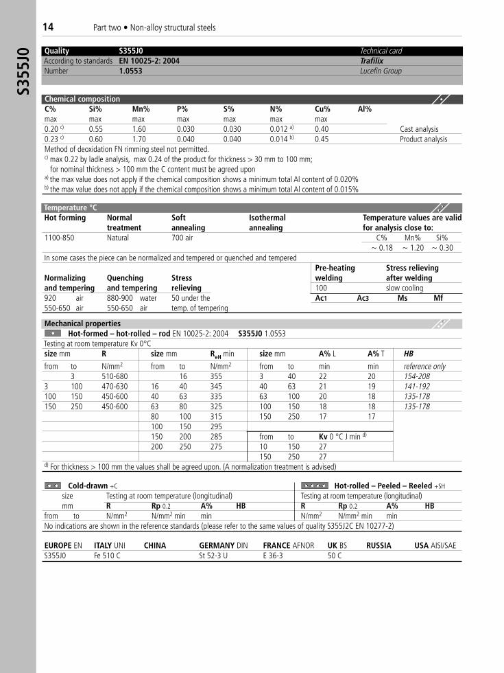
Quality S355J0 Technical cardAccording to standards EN 10025-2: 2004 TrafilixNumber 1.0553 Lucefin Group
Chemical compositionC% Si% Mn% P% S% N% Cu% Al%max max max max max max max0.20 c) 0.55 1.60 0.030 0.030 0.012 a) 0.40 Cast analysis0.23 c) 0.60 1.70 0.040 0.040 0.014 b) 0.45 Product analysisMethod of deoxidation FN rimming steel not permitted.c) max 0.22 by ladle analysis, max 0.24 of the product for thickness > 30 mm to 100 mm;
for nominal thickness > 100 mm the C content must be agreed upona) the max value does not apply if the chemical composition shows a minimum total Al content of 0.020%b) the max value does not apply if the chemical composition shows a minimum total Al content of 0.015%
Temperature °CHot forming Normal Soft Isothermal Temperature values are valid
treatment annealing annealing for analysis close to:1100-850 Natural 700 air C% Mn% Si%
~ 0.18 ~ 1.20 ~ 0.30In some cases the piece can be normalized and tempered or quenched and tempered
Pre-heating Stress relievingNormalizing Quenching Stress welding after weldingand tempering and tempering relieving 100 slow cooling920 air 880-900 water 50 under the Ac1 Ac3 Ms Mf550-650 air 550-650 air temp. of tempering
Cold-drawn +C Hot-rolled – Peeled – Reeled +SH
size Testing at room temperature (longitudinal) Testing at room temperature (longitudinal)mm R Rp 0.2 A% HB R Rp 0.2 A% HB
from to N/mm2 N/mm2 min min N/mm2 N/mm2 min minNo indications are shown in the reference standards (please refer to the same values of quality S355J2C EN 10277-2)
EUROPE EN ITALY UNI CHINA GERMANY DIN FRANCE AFNOR UK BS RUSSIA USA AISI/SAES355J0 Fe 510 C St 52-3 U E 36-3 50 C
Mechanical propertiesHot-formed – hot-rolled – rod EN 10025-2: 2004 S355J0 1.0553
Testing at room temperature Kv 0°Csize mm R size mm ReH min size mm A% L A% T HB
from to N/mm2 from to N/mm2 from to min min reference only3 510-680 16 355 3 40 22 20 154-208
3 100 470-630 16 40 345 40 63 21 19 141-192100 150 450-600 40 63 335 63 100 20 18 135-178150 250 450-600 63 80 325 100 150 18 18 135-178
80 100 315 150 250 17 17100 150 295150 200 285 from to Kv 0 °C J min d)
200 250 275 10 150 27150 250 27
d) For thickness > 100 mm the values shall be agreed upon. (A normalization treatment is advised)
S355
J0
Part two • Non-alloy structural steels 15S3
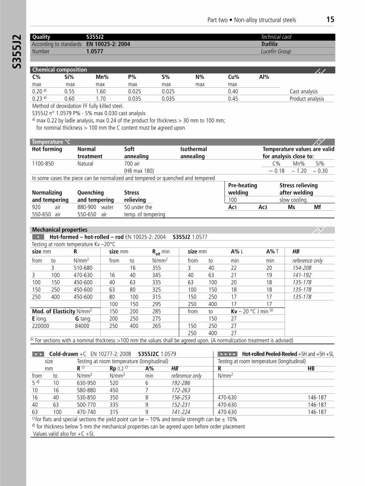
55J2 Quality S355J2 Technical card
According to standards EN 10025-2: 2004 TrafilixNumber 1.0577 Lucefin Group
Chemical compositionC% Si% Mn% P% S% N% Cu% Al%max max max max max max max0.20 a) 0.55 1.60 0.025 0.025 0.40 Cast analysis0.23 a) 0.60 1.70 0.035 0.035 0.45 Product analysisMethod of deoxidation FF fully killed steel.S355J2 n° 1.0579 P% - S% max 0.030 cast analysisa) max 0.22 by ladle analysis, max 0.24 of the product for thickness > 30 mm to 100 mm;
for nominal thickness > 100 mm the C content must be agreed upon
Temperature °C Hot forming Normal Soft Isothermal Temperature values are valid
treatment annealing annealing for analysis close to:1100-850 Natural 700 air C% Mn% Si%
(HB max 180) ~ 0.18 ~ 1.20 ~ 0.30In some cases the piece can be normalized and tempered or quenched and tempered
Pre-heating Stress relievingNormalizing Quenching Stress welding after weldingand tempering and tempering relieving 100 slow cooling920 air 880-900 water 50 under the Ac1 Ac3 Ms Mf550-650 air 550-650 air temp. of tempering
Mechanical propertiesHot-formed – hot-rolled – rod EN 10025-2: 2004 S355J2 1.0577
Testing at room temperature Kv –20°Csize mm R size mm ReH min size mm A% L A% T HB
from to N/mm2 from to N/mm2 from to min min reference only3 510-680 16 355 3 40 22 20 154-208
3 100 470-630 16 40 345 40 63 21 19 141-192100 150 450-600 40 63 335 63 100 20 18 135-178150 250 450-600 63 80 325 100 150 18 18 135-178250 400 450-600 80 100 315 150 250 17 17 135-178
100 150 295 250 400 17 17Mod. of Elasticity N/mm2 150 200 285 from to Kv – 20 °C J min b)
E long. G tang. 200 250 275 150 27 220000 84000 250 400 265 150 250 27
250 400 27b) For sections with a nominal thickness >100 mm the values shall be agreed upon. (A normalization treatment is advised)
Cold-drawn +C EN 10277-2: 2008 S355J2C 1.0579 Hot-rolled Peeled-Reeled +SH and +SH +SLsize Testing at room temperature (longitudinal) Testing at room temperature (longitudinal)mm R c) Rp 0.2 c) A% HB R HB
from to N/mm2 N/mm2 min reference only N/mm2
5 d) 10 630-950 520 6 192-28610 16 580-880 450 7 172-26316 40 530-850 350 8 156-253 470-630 146-18740 63 500-770 335 9 152-231 470-630 146-18763 100 470-740 315 9 141-224 470-630 146-187c) for flats and special sections the yield point can be – 10% and tensile strength can be ± 10%d) for thickness below 5 mm the mechanical properties can be agreed upon before order placementValues valid also for +C +SL
16 Part two • Non-alloy structural steels
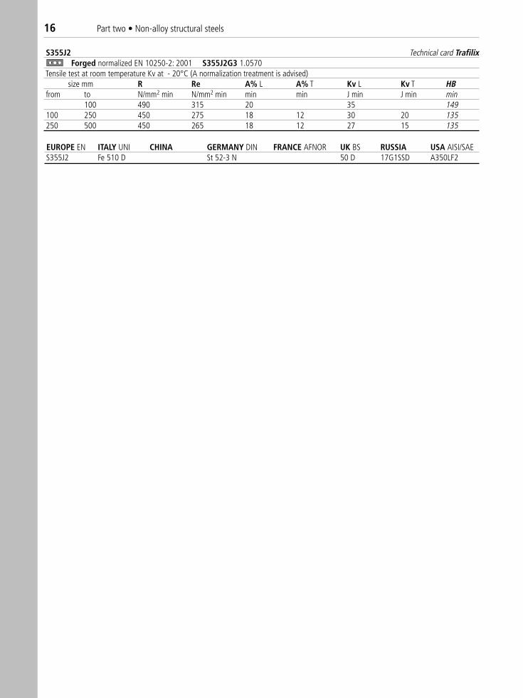
S355J2 Technical card TrafilixForged normalized EN 10250-2: 2001 S355J2G3 1.0570
Tensile test at room temperature Kv at - 20°C (A normalization treatment is advised)size mm R Re A% L A% T Kv L Kv T HB
from to N/mm2 min N/mm2 min min min J min J min min100 490 315 20 35 149
100 250 450 275 18 12 30 20 135250 500 450 265 18 12 27 15 135
EUROPE EN ITALY UNI CHINA GERMANY DIN FRANCE AFNOR UK BS RUSSIA USA AISI/SAE S355J2 Fe 510 D St 52-3 N 50 D 17G1SSD A350LF2
Part two • Non-alloy structural steels 17E2
95
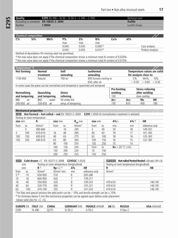
Quality E295 (Fe 490 – Fe 50 – St 50-2 – C 30E – C 35E) Technical cardAccording to standards EN 10025-2: 2004 TrafilixNumber 1.0050 Lucefin Group
Chemical compositionC% Si% Mn% P% S% N% Cu% Al%
max max max0.045 0.045 0.009 a) Cast analysis0.055 0.055 0.014 b) Product analysis
Method of deoxidation FN rimming steel not permitted.a) the max value does not apply if the chemical composition shows a minimum total Al content of 0.020% b) the max value does not apply if the chemical composition shows a minimum total Al content of 0.015%
Temperature °C Hot forming Normal Soft Isothermal Temperature values are valid
treatment annealing annealing for analysis close to:1150-850 Natural 700 air 850 furnace cooling to C% Mn% Si%
650, after air ~ 0.30 ~ 0.60 ~ 0.30In some cases the piece can be normalized and tempered or quenched and tempered
Pre-heating Stress relievingNormalizing Quenching Stress welding after weldingand tempering and tempering relieving 100 slow cooling880 air 860 water 50 under the Ac1 Ac3 Ms Mf540-650 air 550-650 air temp. of tempering 730 810 400 180
Mechanical propertiesHot-formed – hot-rolled – rod EN 10025-2: 2004 E295 1.0050 (A normalization treatment is advised)
Testing at room temperaturesize mm R size mm ReH min size mm A% L A% T HB
from to N/mm2 from to N/mm2 from to min min reference only3 490-660 16 295 3 40 20 18 149-202
3 100 470-610 16 40 285 40 63 19 17 141-183100 150 450-610 40 63 275 63 100 18 16 135-183150 250 440-610 63 80 265 100 150 16 15 132-183
80 100 255 150 250 15 14100 150 245 from to Kv + 20 °C J min 150 200 235 10 150200 250 225 150 250
Cold-drawn +C EN 10277-2: 2008 E295GC 1.0533 Hot-rolled Peeled-Reeled +SH and +SH +SLsize Testing at room temperature (longitudinal) Testing at room temperature (longitudinal)mm R c) Rp 0.2 c) A% HB R HB
from to N/mm2 N/mm2 min min reference only N/mm2
5 d) 10 650-950 510 6 200-28610 16 600-900 420 7 178-27116 40 550-850 320 8 159-253 470-610 140-18140 63 520-770 300 9 155-231 470-610 140-18163 100 470-740 255 9 141-224 470-610 140-181c) for flats and special sections the yield point can be – 10% and tensile strength can be ± 10%d) for thickness below 5 mm the mechanical properties can be agreed upon before order placement Values valid also for +C +SL
EUROPE EN ITALY UNI CHINA GERMANY DIN FRANCE AFNOR UK BS RUSSIA USA AISI/SAE E295 Fe 490 Q275 St 50-2 A 50-2 S15ps-2
18 Part two • Non-alloy structural steels
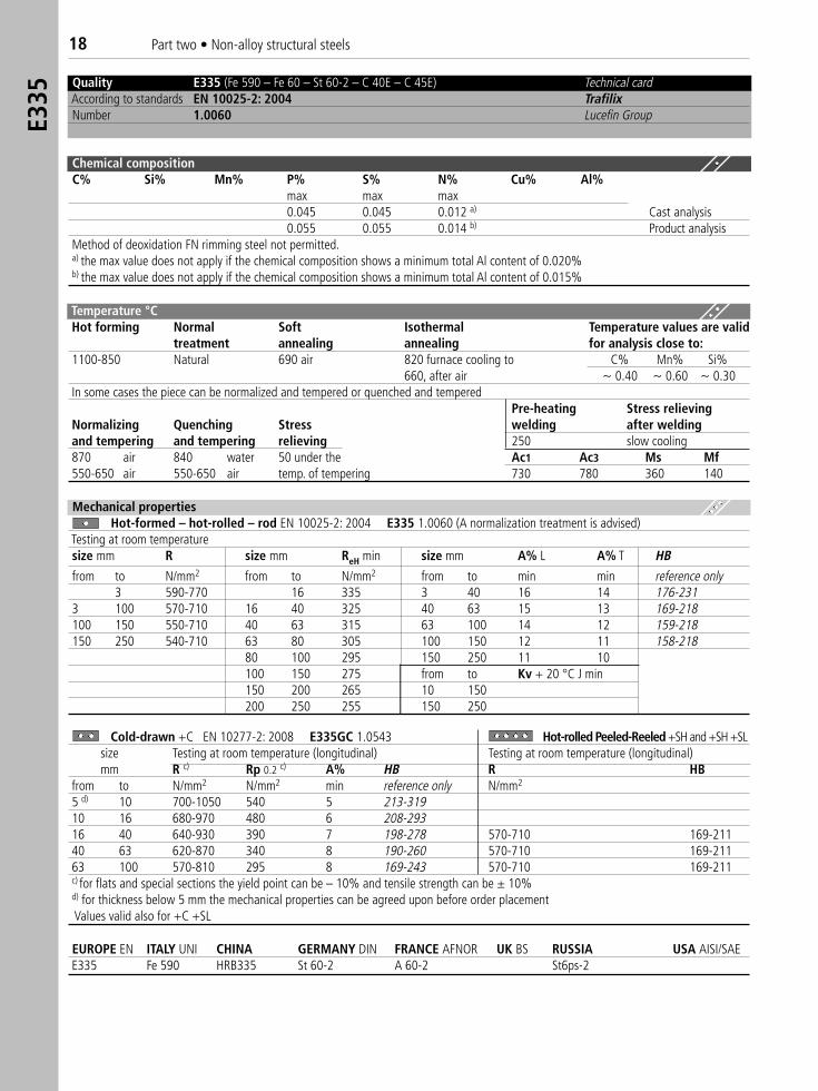
Quality E335 (Fe 590 – Fe 60 – St 60-2 – C 40E – C 45E) Technical cardAccording to standards EN 10025-2: 2004 TrafilixNumber 1.0060 Lucefin Group
Chemical compositionC% Si% Mn% P% S% N% Cu% Al%
max max max0.045 0.045 0.012 a) Cast analysis0.055 0.055 0.014 b) Product analysis
Method of deoxidation FN rimming steel not permitted.a) the max value does not apply if the chemical composition shows a minimum total Al content of 0.020% b) the max value does not apply if the chemical composition shows a minimum total Al content of 0.015%
Temperature °CHot forming Normal Soft Isothermal Temperature values are valid
treatment annealing annealing for analysis close to:1100-850 Natural 690 air 820 furnace cooling to C% Mn% Si%
660, after air ~ 0.40 ~ 0.60 ~ 0.30In some cases the piece can be normalized and tempered or quenched and tempered
Pre-heating Stress relievingNormalizing Quenching Stress welding after weldingand tempering and tempering relieving 250 slow cooling870 air 840 water 50 under the Ac1 Ac3 Ms Mf550-650 air 550-650 air temp. of tempering 730 780 360 140
Mechanical propertiesHot-formed – hot-rolled – rod EN 10025-2: 2004 E335 1.0060 (A normalization treatment is advised)
Testing at room temperaturesize mm R size mm ReH min size mm A% L A% T HB
from to N/mm2 from to N/mm2 from to min min reference only3 590-770 16 335 3 40 16 14 176-231
3 100 570-710 16 40 325 40 63 15 13 169-218100 150 550-710 40 63 315 63 100 14 12 159-218150 250 540-710 63 80 305 100 150 12 11 158-218
80 100 295 150 250 11 10100 150 275 from to Kv + 20 °C J min 150 200 265 10 150200 250 255 150 250
Cold-drawn +C EN 10277-2: 2008 E335GC 1.0543 Hot-rolled Peeled-Reeled +SH and +SH +SLsize Testing at room temperature (longitudinal) Testing at room temperature (longitudinal)mm R c) Rp 0.2 c) A% HB R HB
from to N/mm2 N/mm2 min reference only N/mm2
5 d) 10 700-1050 540 5 213-31910 16 680-970 480 6 208-29316 40 640-930 390 7 198-278 570-710 169-21140 63 620-870 340 8 190-260 570-710 169-21163 100 570-810 295 8 169-243 570-710 169-211c) for flats and special sections the yield point can be – 10% and tensile strength can be ± 10% d) for thickness below 5 mm the mechanical properties can be agreed upon before order placementValues valid also for +C +SL
EUROPE EN ITALY UNI CHINA GERMANY DIN FRANCE AFNOR UK BS RUSSIA USA AISI/SAEE335 Fe 590 HRB335 St 60-2 A 60-2 St6ps-2
E335
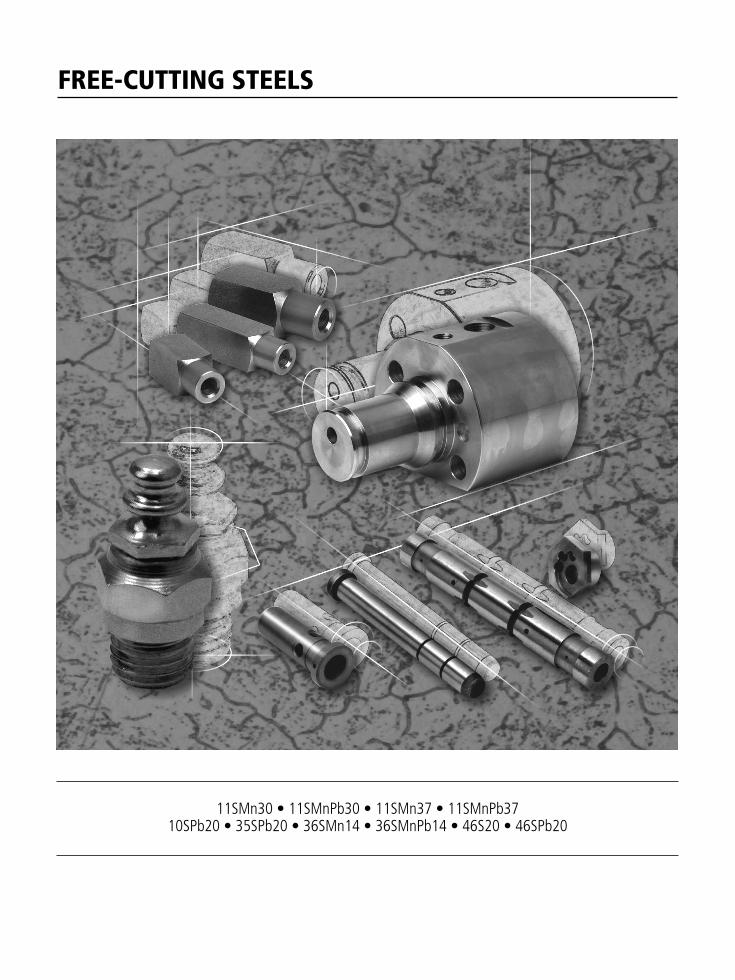
FREE-CUTTING STEELS
11SMn30 • 11SMnPb30 • 11SMn37 • 11SMnPb37 10SPb20 • 35SPb20 • 36SMn14 • 36SMnPb14 • 46S20 • 46SPb20
20 Part two • Free-cutting steels11
SMn3
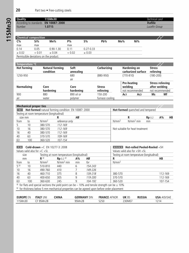
0 Quality 11SMn30 Technical cardAccording to standards EN 10087: 2000 TrafilixNumber 1.0715 Lucefin Group
Chemical compositionC% Si% Mn% P% S% Pb% Mo% Ni%max max max0.14 0.05 0.90-1.30 0.11 0.27-0.33± 0.02 + 0.01 ± 0.04 + 0.02 ± 0.03Permissible deviations on the product.
Temperature °C Hot forming Natural forming Soft Carburizing Hardening on Stress
condition annealing carburized surface relieving1250-950 680 (880-950) (770-810) (180-200)
airPre-heating Stress relieving
Normalizing Core Core Stress welding after weldinghardening hardening relieving not recommended not recommended
900 880 890 oil or 150-200 Ac1 Ac3 Ms Mfair water polymer furnace cooling
Mechanical proper tiesHot-formed natural forming condition EN 10087: 2000 Hot-formed quenched and tempered
Testing at room temperature (longitudinal)size mm R HB R Rp 0.2 A% HB
from to N/mm2 reference only N/mm2 N/mm2 min min5 10 380-570 112-16910 16 380-570 112-169 Not suitable for heat treatment16 40 380-570 112-16940 63 370-570 109-16963 100 360-520 107-154
Cold-drawn +C EN 10277-3: 2008 Hot-rolled Peeled-Reeled +SH� �Values valid also for +C +SL Values valid also for +SH +SL�
size Testing at room temperature (longitudinal) Testing at room temperature (longitudinal)mm R a) Rp 0.2 a) A% HB R HB
from to N/mm2 N/mm2 min min for N/mm2
5 b) 10 510-810 440 6 154-24310 16 490-760 410 7 149-22616 40 460-710 375 8 139-218 380-570 112-16940 63 400-650 305 9 119-200 370-570 112-16963 100 360-630 245 9 104-192 360-520 107-154a) for flats and special sections the yield point can be – 10% and tensile strength can be ± 10% b) for thickness below 5 mm mechanical properties can be agreed upon before order placement
EUROPE EN ITALY UNI CHINA GERMANY DIN FRANCE AFNOR UK BS RUSSIA USA AISI/SAE11SMn30 CF 9SMn28 9SMn28 S250 230M07 1214
Part two • Free-cutting steels 2111
SMnP
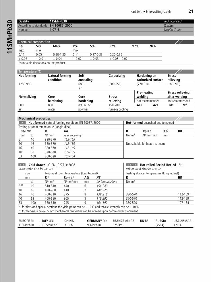
b30 Quality 11SMnPb30 Technical card
According to standards EN 10087: 2000 TrafilixNumber 1.0718 Lucefin Group
Chemical compositionC% Si% Mn% P% S% Pb% Mo% Ni%max max max0.14 0.05 0.90-1.30 0.11 0.27-0.33 0.20-0.35± 0.02 + 0.01 ± 0.04 + 0.02 ± 0.03 + 0.03 – 0.02Permissible deviations on the product.
Mechanical propertiesHot-formed natural forming condition EN 10087: 2000 Hot-formed quenched and tempered
Testing at room temperature (longitudinal)size mm R HB R Rp 0.2 A% HB
from to N/mm2 reference only N/mm2 N/mm2 min min5 10 380-570 112-16910 16 380-570 112-169 Not suitable for heat treatment16 40 380-570 112-16940 63 370-570 109-16963 100 360-520 107-154
Cold-drawn +C EN 10277-3: 2008 Hot-rolled Peeled-Reeled +SH � �Values valid also for +C +SL Values valid also for +SH +SL�
size Testing at room temperature (longitudinal) Testing at room temperature (longitudinal)mm R a) Rp 0.2 a) A% HB R HB
to N/mm2 N/mm2 min min for informazione N/mm2
5 b) 10 510-810 440 6 154-24310 16 490-760 410 7 149-22616 40 460-710 375 8 139-218 380-570 112-16940 63 400-650 305 9 119-200 370-570 112-16963 100 360-630 245 9 104-192 360-520 107-154a) for flats and special sections the yield point can be – 10% and tensile strength can be ± 10%b) for thickness below 5 mm mechanical properties can be agreed upon before order placement
EUROPE EN ITALY UNI CHINA GERMANY DIN FRANCE AFNOR UK BS RUSSIA USA AISI/SAE 11SMnPb30 CF 9SMnPb28 Y15Pb 9SMnPb28 S250Pb (AS14) 12L14
Temperature °C Hot forming Natural forming Soft Carburizing Hardening on Stress
condition annealing carburized surface relieving1250-950 680 (880-950) (770-810) (180-200)
airPre-heating Stress relieving
Normalizing Core Core Stress welding after weldinghardening hardening relieving not recommended not recommended
900 880 890 oil or 150-200 Ac1 Ac3 Ms Mfair water polymer furnace cooling
22 Part two • Free-cutting steels11
SMn3
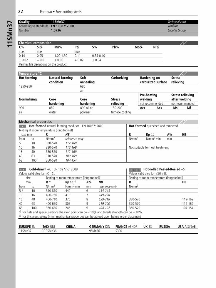
7 Quality 11SMn37 Technical cardAccording to standards EN 10087: 2000 TrafilixNumber 1.0736 Lucefin Group
Chemical compositionC% Si% Mn% P% S% Pb% Mo% Ni%max max max0.14 0.05 1.00-1.50 0.11 0.34-0.40± 0.02 + 0.01 ± 0.06 + 0.02 ± 0.04Permissible deviations on the product.
Temperature °CHot forming Natural forming Soft Carburizing Hardening on Stress
condition annealing carburized surface relieving1250-950 680
airPre-heating Stress relieving
Normalizing Core Core Stress welding after weldinghardening hardening relieving not recommended not recommended
900 880 890 oil or 150-200 Ac1 Ac3 Ms Mfair water polymer furnace cooling
Mechanical propertiesHot-formed natural forming condition EN 10087: 2000 Hot-formed quenched and tempered
Testing at room temperature (longitudinal)size mm R HB R Rp 0.2 A% HB
from to N/mm2 reference only N/mm2 N/mm2 min min5 10 380-570 112-16910 16 380-570 112-169 Not suitable for heat treatment16 40 380-570 112-16940 63 370-570 109-16963 100 360-520 107-154
Cold-drawn +C EN 10277-3: 2008 Hot-rolled Peeled-Reeled +SH � �Values valid also for +C +SL Values valid also for +SH +SL�
size Testing at room temperature (longitudinal) Testing at room temperature (longitudinal)mm R a) Rp 0.2 a) A% HB R HB
from to N/mm2 N/mm2 min min reference only N/mm2
5 b) 10 510-810 440 6 154-24310 16 490-760 410 7 149-22616 40 460-710 375 8 139-218 380-570 112-16940 63 400-650 305 9 119-200 370-570 112-16963 100 360-630 245 9 104-192 360-520 107-154a) for flats and special sections the yield point can be – 10% and tensile strength can be ± 10%b) for thickness below 5 mm mechanical properties can be agreed upon before order placement
EUROPE EN ITALY UNI CHINA GERMANY DIN FRANCE AFNOR UK BS RUSSIA USA AISI/SAE 11SMn37 CF 9SMn36 9SMn36 S300
Part two • Free-cutting steels 23
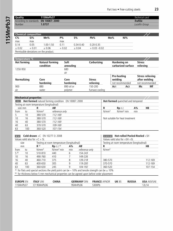
Quality 11SMnPb37 Technical cardAccording to standards EN 10087: 2000 TrafilixNumber 1.0737 Lucefin Group
Chemical compositionC% Si% Mn% P% S% Pb% Mo% Ni%max max max0.14 0.05 1.00-1.50 0.11 0.34-0.40 0.20-0.35± 0.02 + 0.01 ± 0.06 + 0.02 ± 0.04 + 0.03 –0.02Permissible deviations on the product.
Mechanical propertiesHot-formed natural forming condition EN 10087: 2000 Hot-formed quenched and tempered
Testing at room temperature (longitudinal)size mm R HB R Rp 0.2 A% HB
from to N/mm2 reference only N/mm2 N/mm2 min min5 10 380-570 112-16910 16 380-570 112-169 Not suitable for heat treatment16 40 380-570 112-16940 63 370-570 109-16963 100 360-520 107-154
Cold-drawn +C EN 10277-3: 2008 Hot-rolled Peeled-Reeled +SH � �Values valid also for +C + SL Values valid also for +SH +SL
size Testing at room temperature (longitudinal) Testing at room temperature (longitudinal)mm R a) Rp 0.2 a) A% HB R HB
from to N/mm2 N/mm2 min min reference only N/mm2
5 b) 10 510-810 440 6 154-24310 16 490-760 410 7 149-22616 40 460-710 375 8 139-218 380-570 112-16940 63 400-650 305 9 119-200 370-570 112-16963 100 360-630 245 9 104-192 360-520 107-154a) for flats and special sections the yield point can be – 10% and tensile strength can be ± 10%b) for thickness below 5 mm mechanical properties can be agreed upon before order placement
EUROPE EN ITALY UNI CHINA GERMANY DIN FRANCE AFNOR UK BS RUSSIA USA AISI/SAE 11SMnPb37 CF 9SMnPb36 9SMnPb36 S300Pb 12L14
Temperature °CHot forming Natural forming Soft Carburizing Hardening on Stress
condition annealing carburized surface relieving1250-950 680
airPre-heating Stress relieving
Normalizing Core Core Stress welding after weldinghardening hardening relieving not recommended not recommended
900 880 890 oil or 150-200 Ac1 Ac3 Ms Mfair water polymer furnace cooling
11SM
nPb3
7
24 Part two • Free-cutting steels10
SPb2
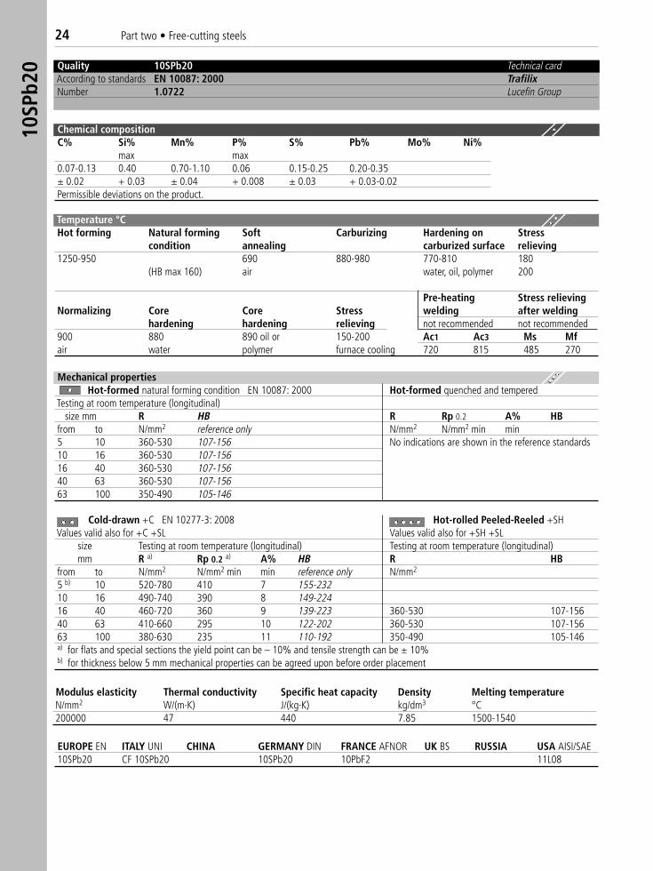
0 Quality 10SPb20 Technical cardAccording to standards EN 10087: 2000 TrafilixNumber 1.0722 Lucefin Group
Chemical compositionC% Si% Mn% P% S% Pb% Mo% Ni%
max max0.07-0.13 0.40 0.70-1.10 0.06 0.15-0.25 0.20-0.35± 0.02 + 0.03 ± 0.04 + 0.008 ± 0.03 + 0.03-0.02Permissible deviations on the product.
Temperature °CHot forming Natural forming Soft Carburizing Hardening on Stress
condition annealing carburized surface relieving1250-950 690 880-980 770-810 180
(HB max 160) air water, oil, polymer 200
Pre-heating Stress relievingNormalizing Core Core Stress welding after welding
hardening hardening relieving not recommended not recommended900 880 890 oil or 150-200 Ac1 Ac3 Ms Mfair water polymer furnace cooling 720 815 485 270
Mechanical propertiesHot-formed natural forming condition EN 10087: 2000 Hot-formed quenched and tempered
Testing at room temperature (longitudinal)size mm R HB R Rp 0.2 A% HB
from to N/mm2 reference only N/mm2 N/mm2 min min5 10 360-530 107-156 No indications are shown in the reference standards10 16 360-530 107-15616 40 360-530 107-15640 63 360-530 107-15663 100 350-490 105-146
Cold-drawn +C EN 10277-3: 2008 Hot-rolled Peeled-Reeled +SH� �Values valid also for +C +SL Values valid also for +SH +SL�
size Testing at room temperature (longitudinal) Testing at room temperature (longitudinal)mm R a) Rp 0.2 a) A% HB R HB
from to N/mm2 N/mm2 min min reference only N/mm2
5 b) 10 520-780 410 7 155-23210 16 490-740 390 8 149-22416 40 460-720 360 9 139-223 360-530 107-15640 63 410-660 295 10 122-202 360-530 107-15663 100 380-630 235 11 110-192 350-490 105-146a) for flats and special sections the yield point can be – 10% and tensile strength can be ± 10%b) for thickness below 5 mm mechanical properties can be agreed upon before order placement
EUROPE EN ITALY UNI CHINA GERMANY DIN FRANCE AFNOR UK BS RUSSIA USA AISI/SAE 10SPb20 CF 10SPb20 10SPb20 10PbF2 11L08
Modulus elasticity Thermal conductivity Specific heat capacity Density Melting temperatureN/mm2 W/(m·K) J/(kg·K) kg/dm3 °C200000 47 440 7.85 1500-1540
Part two • Free-cutting steels 2535
SPb2
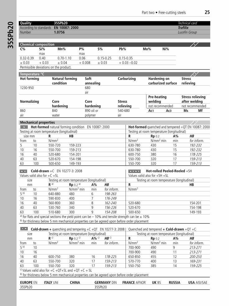
0 Quality 35SPb20 Technical cardAccording to standards EN 10087: 2000 TrafilixNumber 1.0756 Lucefin Group
Chemical compositionC% Si% Mn% P% S% Pb% Mo% Ni%
max max0.32-0.39 0.40 0.70-1.10 0.06 0.15-0.25 0.15-0.35± 0.03 + 0.03 ± 0.04 + 0.008 ± 0.03 + 0.03 –0.02Permissible deviations on the product.
Temperature °C Hot forming Natural forming Soft Carburizing Hardening on Stress
condition annealing carburized surface relieving1230-950 680
airPre-heating Stress relieving
Normalizing Core Core Stress welding after weldinghardening hardening relieving not recommended not recommended
860 840 890 oil or 540-680 Ac1 Ac3 Ms Mfair water polymer air
Mechanical propertiesHot-formed natural forming condition EN 10087: 2000 Hot-formed quenched and tempered +QT EN 10087: 2000
Testing at room temperature (longitudinal) Testing at room temperature (longitudinal)size mm R HB R Rp 0.2 A% HB
from to N/mm2 N/mm2 N/mm2 min min for inform.5 10 550-720 159-223 630-780 430 15 192-23210 16 550-700 159-213 630-780 430 15 192-23216 40 520-680 154-201 600-750 380 16 178-22540 63 520-670 154-198 550-700 320 17 159-21363 100 500-650 149-193 550-700 320 17 159-213
Cold-drawn +C EN 10277-3: 2008 Hot-rolled Peeled-Reeled +SH � �Values valid also for +C +SL Values valid also for +SH +SL�
size Testing at room temperature (longitudinal) Testing at room temperature (longitudinal)mm R a) Rp 0.2 a) A% HB R HB
from to N/mm2 N/mm2 min min for inform. N/mm2
5 b) 10 640-880 480 6 198-26310 16 590-830 400 7 176-24916 40 560-800 360 8 162-240 520-680 154-20140 63 530-760 340 9 156-226 520-670 154-19863 100 510-680 300 9 154-208 500-650 149-193a) for flats and special sections the yield point can be – 10% and tensile strength can be ± 10%b) for thickness below 5 mm mechanical properties can be agreed upon before order placement
Cold-drawn + quenching and tempering +C +QT EN 10277-3: 2008 Quenched and tempered + Cold-drawn +QT +Csize Testing at room temperature (longitudinal) Testing at room temperature (longitudinal)mm R c) Rp 0.2 c) A% c) HB c) R Rp 0.2 A% HB
from to N/mm2 N/mm2 min min for inform. N/mm2 N/mm2 min min for inform.5 b) 10 700-900 490 9 213-27110 16 700-900 490 11 213-27116 40 600-750 380 16 178-225 650-850 455 12 200-25340 63 550-700 320 17 159-213 570-770 400 13 169-23163 100 550-700 320 17 159-213 550-750 385 14 159-225c) Values valid also for +C +QT+SL and +QT +C + SLb) for thickness below 5 mm mechanical properties can be agreed upon before order placement
EUROPE EN ITALY UNI CHINA GERMANY DIN FRANCE AFNOR UK BS RUSSIA USA AISI/SAE 35SPb20 35SPb20
Cold-drawn +C EN 10277-3: 2008 Hot-rolled Peeled-Reeled +SH � �Values valid also for +C +SL Values valid also for +SH +SL�
size Testing at room temperature (longitudinal) Testing at room temperature (longitudinal)mm R a) Rp 0.2 a) A% HB R HB
from to N/mm2 N/mm2 min min for inform. N/mm2
5 b) 10 660-960 500 6 202-29010 16 620-920 440 6 190-27516 40 600-900 390 7 178-271 560-750 166-22240 63 580-840 360 8 172-250 560-740 166-21963 100 560-820 340 9 162-246 550-740 163-219a) for flats and special sections the yield point can be – 10% and tensile strength can be ± 10%b) for thickness below 5 mm mechanical properties can be agreed upon before order placement
26 Part two • Free-cutting steels36
SMn1
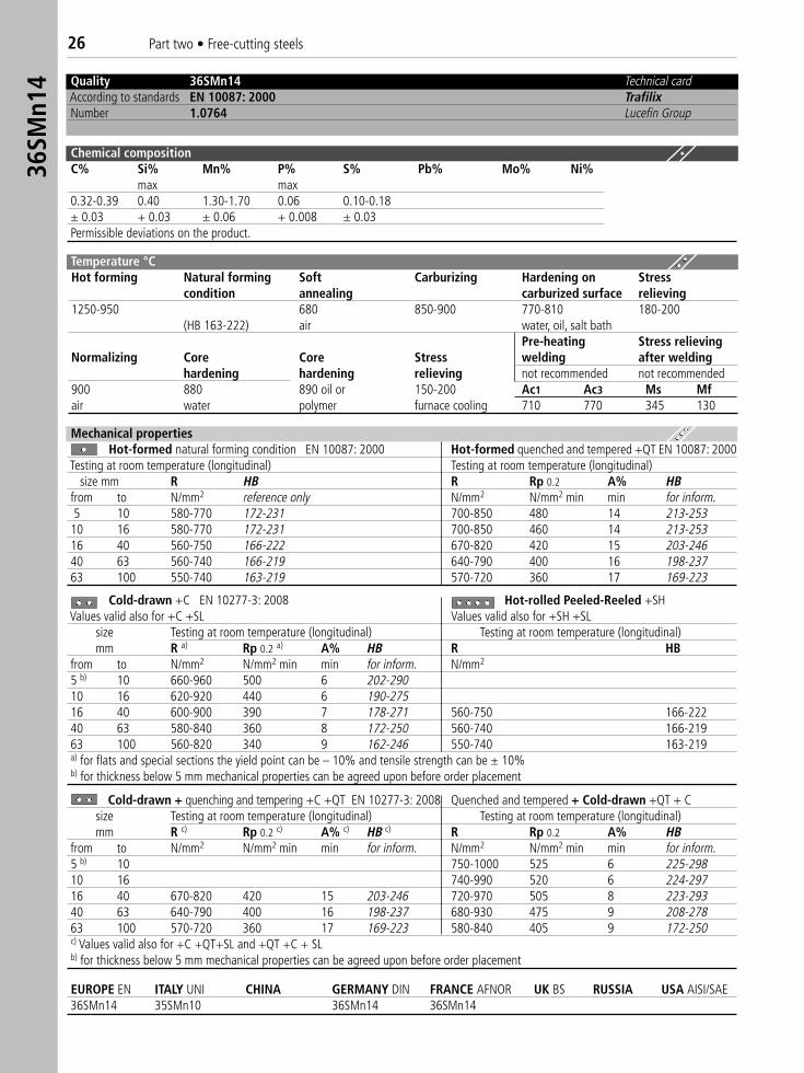
4 Quality 36SMn14 Technical cardAccording to standards EN 10087: 2000 TrafilixNumber 1.0764 Lucefin Group
Chemical compositionC% Si% Mn% P% S% Pb% Mo% Ni%
max max0.32-0.39 0.40 1.30-1.70 0.06 0.10-0.18± 0.03 + 0.03 ± 0.06 + 0.008 ± 0.03Permissible deviations on the product.
Mechanical propertiesHot-formed natural forming condition EN 10087: 2000 Hot-formed quenched and tempered +QT EN 10087: 2000
Testing at room temperature (longitudinal) Testing at room temperature (longitudinal)size mm R HB R Rp 0.2 A% HB
from to N/mm2 reference only N/mm2 N/mm2 min min for inform.5 10 580-770 172-231 700-850 480 14 213-25310 16 580-770 172-231 700-850 460 14 213-25316 40 560-750 166-222 670-820 420 15 203-24640 63 560-740 166-219 640-790 400 16 198-23763 100 550-740 163-219 570-720 360 17 169-223
Cold-drawn + quenching and tempering +C +QT EN 10277-3: 2008 Quenched and tempered + Cold-drawn +QT + Csize Testing at room temperature (longitudinal) Testing at room temperature (longitudinal)mm R c) Rp 0.2 c) A% c) HB c) R Rp 0.2 A% HB
from to N/mm2 N/mm2 min min for inform. N/mm2 N/mm2 min min for inform.5 b) 10 750-1000 525 6 225-29810 16 740-990 520 6 224-29716 40 670-820 420 15 203-246 720-970 505 8 223-29340 63 640-790 400 16 198-237 680-930 475 9 208-27863 100 570-720 360 17 169-223 580-840 405 9 172-250c) Values valid also for +C +QT+SL and +QT +C + SLb) for thickness below 5 mm mechanical properties can be agreed upon before order placement
EUROPE EN ITALY UNI CHINA GERMANY DIN FRANCE AFNOR UK BS RUSSIA USA AISI/SAE 36SMn14 35SMn10 36SMn14 36SMn14
Temperature °CHot forming Natural forming Soft Carburizing Hardening on Stress
condition annealing carburized surface relieving1250-950 680 850-900 770-810 180-200
(HB 163-222) air water, oil, salt bathPre-heating Stress relieving
Normalizing Core Core Stress welding after weldinghardening hardening relieving not recommended not recommended
900 880 890 oil or 150-200 Ac1 Ac3 Ms Mfair water polymer furnace cooling 710 770 345 130
Part two • Free-cutting steels 2736
SMnP
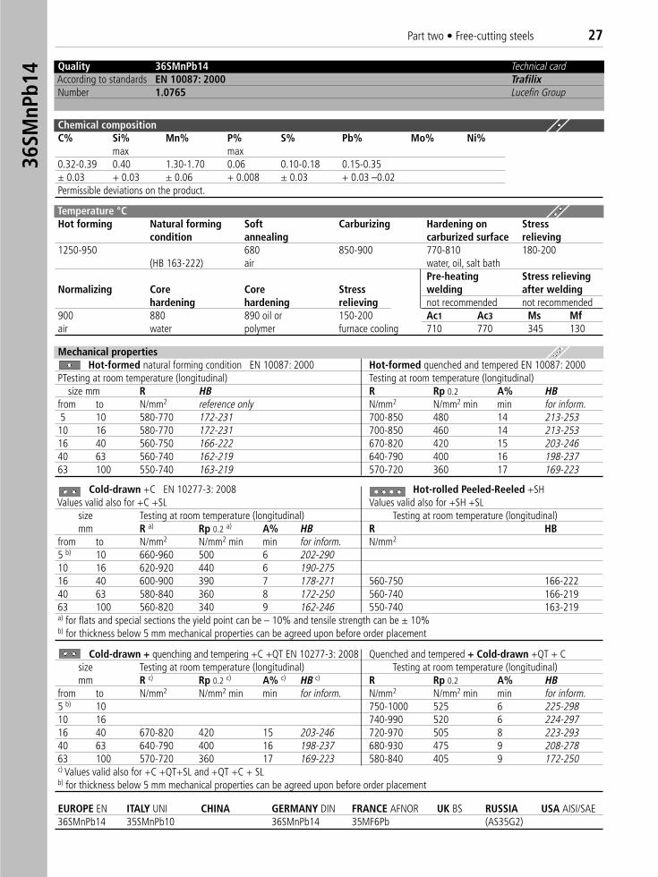
b14 Quality 36SMnPb14 Technical card
According to standards EN 10087: 2000 TrafilixNumber 1.0765 Lucefin Group
Chemical compositionC% Si% Mn% P% S% Pb% Mo% Ni%
max max0.32-0.39 0.40 1.30-1.70 0.06 0.10-0.18 0.15-0.35± 0.03 + 0.03 ± 0.06 + 0.008 ± 0.03 + 0.03 –0.02Permissible deviations on the product.
Mechanical propertiesHot-formed natural forming condition EN 10087: 2000 Hot-formed quenched and tempered EN 10087: 2000
PTesting at room temperature (longitudinal) Testing at room temperature (longitudinal)size mm R HB R Rp 0.2 A% HB
from to N/mm2 reference only N/mm2 N/mm2 min min for inform.5 10 580-770 172-231 700-850 480 14 213-25310 16 580-770 172-231 700-850 460 14 213-25316 40 560-750 166-222 670-820 420 15 203-24640 63 560-740 162-219 640-790 400 16 198-23763 100 550-740 163-219 570-720 360 17 169-223
Cold-drawn +C EN 10277-3: 2008 Hot-rolled Peeled-Reeled +SH � �Values valid also for +C +SL Values valid also for +SH +SL�
size Testing at room temperature (longitudinal) Testing at room temperature (longitudinal)mm R a) Rp 0.2 a) A% HB R HB
from to N/mm2 N/mm2 min min for inform. N/mm2
5 b) 10 660-960 500 6 202-29010 16 620-920 440 6 190-27516 40 600-900 390 7 178-271 560-750 166-22240 63 580-840 360 8 172-250 560-740 166-21963 100 560-820 340 9 162-246 550-740 163-219a) for flats and special sections the yield point can be – 10% and tensile strength can be ± 10%b) for thickness below 5 mm mechanical properties can be agreed upon before order placement
Cold-drawn + quenching and tempering +C +QT EN 10277-3: 2008 Quenched and tempered + Cold-drawn +QT + C �size Testing at room temperature (longitudinal) Testing at room temperature (longitudinal)mm R c) Rp 0.2 c) A% c) HB c) R Rp 0.2 A% HB
from to N/mm2 N/mm2 min min for inform. N/mm2 N/mm2 min min for inform.5 b) 10 750-1000 525 6 225-29810 16 740-990 520 6 224-29716 40 670-820 420 15 203-246 720-970 505 8 223-29340 63 640-790 400 16 198-237 680-930 475 9 208-27863 100 570-720 360 17 169-223 580-840 405 9 172-250c) Values valid also for +C +QT+SL and +QT +C + SLb) for thickness below 5 mm mechanical properties can be agreed upon before order placement
EUROPE EN ITALY UNI CHINA GERMANY DIN FRANCE AFNOR UK BS RUSSIA USA AISI/SAE 36SMnPb14 35SMnPb10 36SMnPb14 35MF6Pb (AS35G2)
Temperature °CHot forming Natural forming Soft Carburizing Hardening on Stress
condition annealing carburized surface relieving1250-950 680 850-900 770-810 180-200
(HB 163-222) air water, oil, salt bathPre-heating Stress relieving
Normalizing Core Core Stress welding after weldinghardening hardening relieving not recommended not recommended
900 880 890 oil or 150-200 Ac1 Ac3 Ms Mfair water polymer furnace cooling 710 770 345 130
28 Part two • Free-cutting steels46
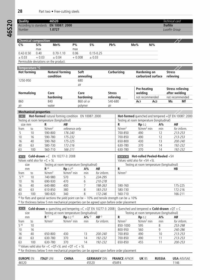
S20 Quality 46S20 Technical card
According to standards EN 10087: 2000 TrafilixNumber 1.0727 Lucefin Group
Chemical compositionC% Si% Mn% P% S% Pb% Mo% Ni%
max max0.42-0.50 0.40 0.70-1.10 0.06 0.15-0.25± 0.03 + 0.03 ± 0.04 + 0.008 ± 0.03Permissible deviations on the product.
Mechanical propertiesHot-formed natural forming condition EN 10087: 2000 Hot-formed quenched and tempered +QT EN 10087: 2000
Testing at room temperature (longitudinal) Testing at room temperature (longitudinal)size mm R HB R Rp 0.2 A% HB
from to N/mm2 reference only N/mm2 N/mm2 min min for inform.5 10 590-800 176-240 700-850 490 12 213-25310 16 590-780 175-232 700-850 490 12 213-25316 40 590-760 175-225 650-800 430 13 200-24040 63 580-730 172-216 630-780 370 14 192-23263 100 560-710 166-211 630-780 370 14 192-232
Cold-drawn +C EN 10277-3: 2008 Hot-rolled Peeled-Reeled +SH��Values valid also for +C + SL Values valid also for +SH +SL�
size Testing at room temperature (longitudinal) Testing at room temperature (longitudinal)mm R a) Rp 0.2a) A% HB R HB
from to N/mm2 N/mm2 min min for inform. N/mm2
5 b) 10 740-980 570 5 224-29510 16 690-930 470 6 210-27816 40 640-880 400 7 198-263 590-760 175-22540 63 610-850 380 8 183-253 580-730 172-21663 100 580-820 340 8 172-246 560-710 166-211a) for flats and special sections the yield point can be – 10% and tensile strength can be ± 10%b) for thickness below 5 mm mechanical properties can be agreed upon before order placement
Cold-drawn + quenching and tempering +C +QT EN 10277-3: 2008 Quenched and tempered + Cold-drawn +QT + Csize Testing at room temperature (longitudinal) Testing at room temperature (longitudinal)mm R c) Rp 0.2 c) A% c) HB c) R Rp 0.2 A% HB
from to N/mm2 N/mm2 min min for inform. N/mm2 N/mm2 min min for inform.5 b) 10 850-1000 595 8 253-29810 16 800-950 560 9 240-28616 40 650-800 430 13 200-240 700-850 490 10 213-25340 63 630-780 370 14 192-232 700-850 490 11 213-25363 100 630-780 370 14 192-232 650-850 455 11 200-253c) Values valid also for +C +QT+SL and +QT +C + SLb) for thickness below 5 mm mechanical properties can be agreed upon before order placement
EUROPE EN ITALY UNI CHINA GERMANY DIN FRANCE AFNOR UK BS RUSSIA USA AISI/SAE46S20 45S20 45MF4 1146
Temperature °CHot forming Natural forming Soft Carburizing Hardening on Stress
condition annealing carburized surface relieving1250-950 680
airPre-heating Stress relieving
Normalizing Core Core Stress welding after weldinghardening hardening relieving not recommended not recommended
860 840 860 oil or 540-680 Ac1 Ac3 Ms Mfair water polymer air
Part two • Free-cutting steels 2946
SPb2
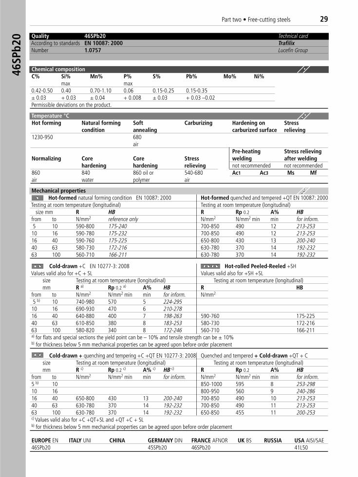
0 Quality 46SPb20 Technical cardAccording to standards EN 10087: 2000 TrafilixNumber 1.0757 Lucefin Group
Chemical compositionC% Si% Mn% P% S% Pb% Mo% Ni%
max max0.42-0.50 0.40 0.70-1.10 0.06 0.15-0.25 0.15-0.35± 0.03 + 0.03 ± 0.04 + 0.008 ± 0.03 + 0.03 –0.02Permissible deviations on the product.
Mechanical propertiesHot-formed natural forming condition EN 10087: 2000 Hot-formed quenched and tempered +QT EN 10087: 2000
Testing at room temperature (longitudinal) Testing at room temperature (longitudinal)size mm R HB R Rp 0.2 A% HB
from to N/mm2 reference only N/mm2 N/mm2 min min for inform.5 10 590-800 175-240 700-850 490 12 213-25310 16 590-780 175-232 700-850 490 12 213-25316 40 590-760 175-225 650-800 430 13 200-24040 63 580-730 172-216 630-780 370 14 192-23263 100 560-710 166-211 630-780 370 14 192-232
Cold-drawn +C EN 10277-3: 2008 Hot-rolled Peeled-Reeled +SH �Values valid also for +C + SL Values valid also for +SH +SL�
size Testing at room temperature (longitudinal) Testing at room temperature (longitudinal)mm R a) Rp 0.2 a) A% HB R HB
from to N/mm2 N/mm2 min min for inform. N/mm2
5 b) 10 740-980 570 5 224-29510 16 690-930 470 6 210-27816 40 640-880 400 7 198-263 590-760 175-22540 63 610-850 380 8 183-253 580-730 172-21663 100 580-820 340 8 172-246 560-710 166-211a) for flats and special sections the yield point can be – 10% and tensile strength can be ± 10%b) for thickness below 5 mm mechanical properties can be agreed upon before order placement
Cold-drawn + quenching and tempering +C +QT EN 10277-3: 2008 Quenched and tempered + Cold-drawn +QT + Csize Testing at room temperature (longitudinal) Testing at room temperature (longitudinal)mm R c) Rp 0.2 c) A% c) HB c) R Rp 0.2 A% HB
from to N/mm2 N/mm2 min min for inform. N/mm2 N/mm2 min min for inform.5 b) 10 850-1000 595 8 253-29810 16 800-950 560 9 240-28616 40 650-800 430 13 200-240 700-850 490 10 213-25340 63 630-780 370 14 192-232 700-850 490 11 213-25363 100 630-780 370 14 192-232 650-850 455 11 200-253c) Values valid also for +C +QT+SL and +QT +C + SLb) for thickness below 5 mm mechanical properties can be agreed upon before order placement
EUROPE EN ITALY UNI CHINA GERMANY DIN FRANCE AFNOR UK BS RUSSIA USA AISI/SAE46SPb20 45SPb20 46SPb20 41L50
Temperature °CHot forming Natural forming Soft Carburizing Hardening on Stress
condition annealing carburized surface relieving1230-950 680
airPre-heating Stress relieving
Normalizing Core Core Stress welding after weldinghardening hardening relieving not recommended not recommended
860 840 860 oil or 540-680 Ac1 Ac3 Ms Mfair water polymer air
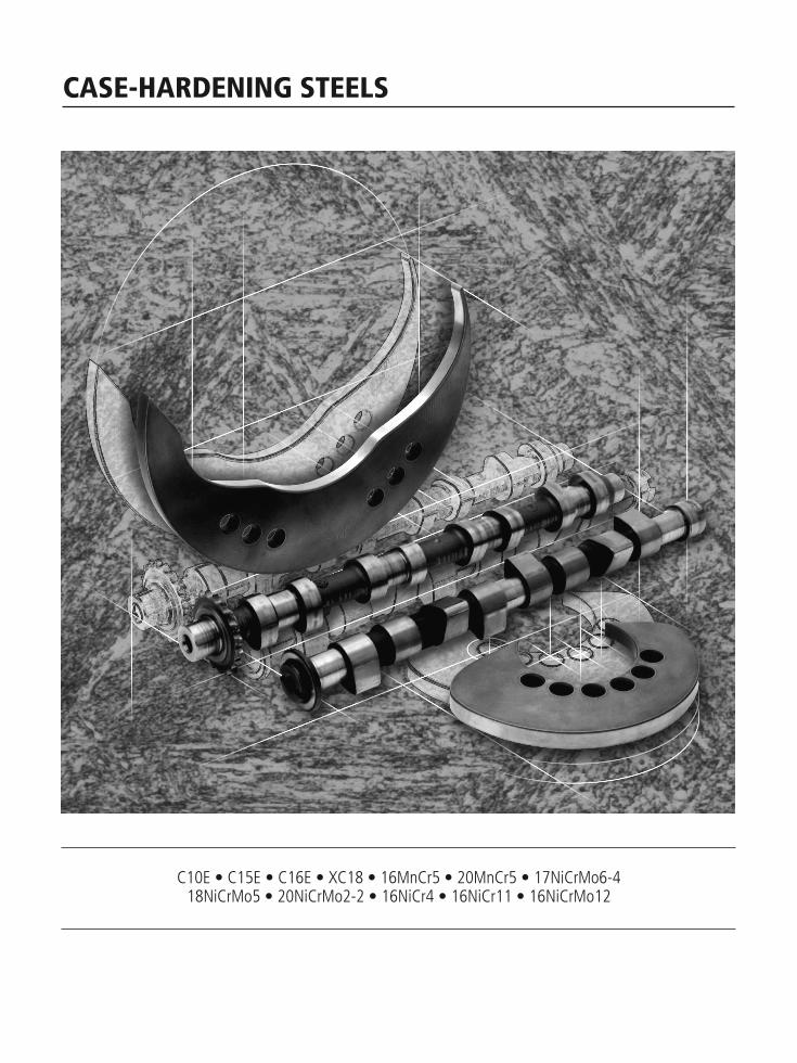
CASE-HARDENING STEELS
C10E • C15E • C16E • XC18 • 16MnCr5 • 20MnCr5 • 17NiCrMo6-418NiCrMo5 • 20NiCrMo2-2 • 16NiCr4 • 16NiCr11 • 16NiCrMo12
C10E
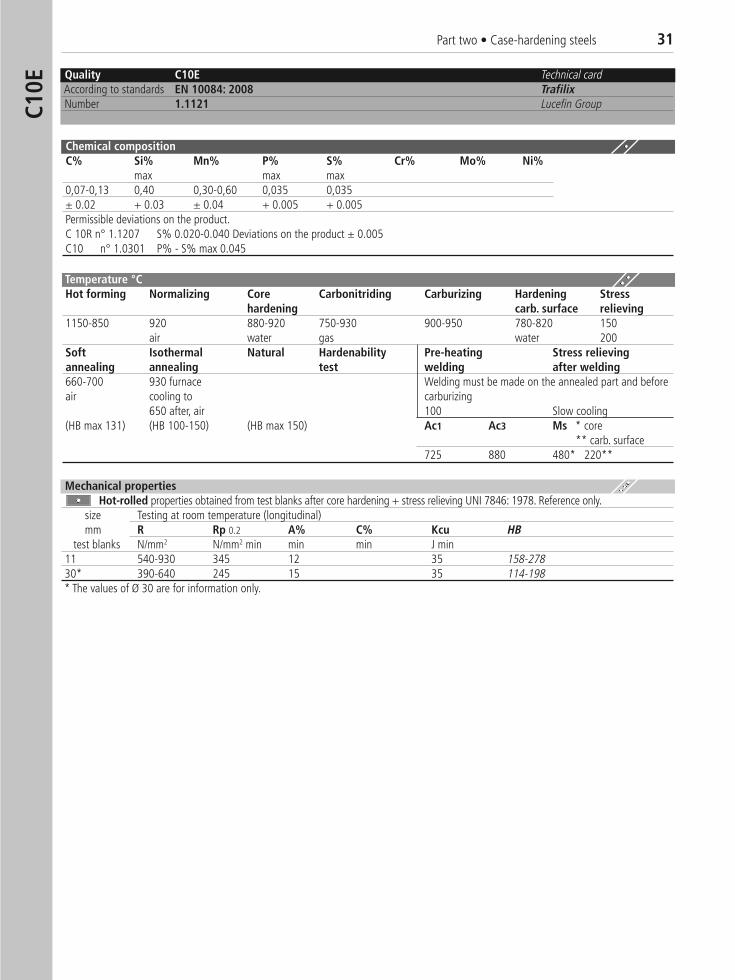
Quality C10E Technical cardAccording to standards EN 10084: 2008 TrafilixNumber 1.1121 Lucefin Group
Chemical compositionC% Si% Mn% P% S% Cr% Mo% Ni%
max max max0,07-0,13 0,40 0,30-0,60 0,035 0,035± 0.02 + 0.03 ± 0.04 + 0.005 + 0.005Permissible deviations on the product.C 10R n° 1.1207 S% 0.020-0.040 Deviations on the product ± 0.005C10 n° 1.0301 P% - S% max 0.045
Temperature °C Hot forming Normalizing Core Carbonitriding Carburizing Hardening Stress
hardening carb. surface relieving1150-850 920 880-920 750-930 900-950 780-820 150
air water gas water 200Soft Isothermal Natural Hardenability Pre-heating Stress relievingannealing annealing test welding after welding660-700 930 furnace Welding must be made on the annealed part and beforeair cooling to carburizing
650 after, air 100 Slow cooling(HB max 131) (HB 100-150) (HB max 150) Ac1 Ac3 Ms * core
** carb. surface725 880 480* 220**
Mechanical propertiesHot-rolled properties obtained from test blanks after core hardening + stress relieving UNI 7846: 1978. Reference only.
size Testing at room temperature (longitudinal)mm R Rp 0.2 A% C% Kcu HB
test blanks N/mm2 N/mm2 min min min J min11 540-930 345 12 35 158-27830* 390-640 245 15 35 114-198* The values of Ø 30 are for information only.
Part two • Case-hardening steels 31
32 Part two • Case-hardening steels
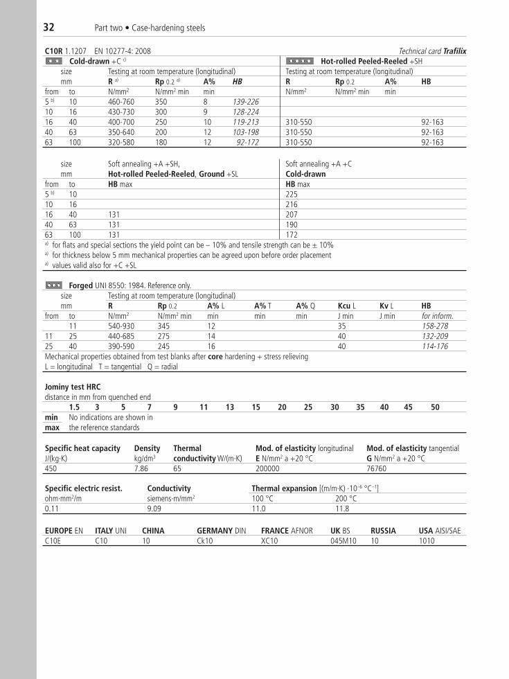
C10R 1.1207 EN 10277-4: 2008 Technical card TrafilixCold-drawn +C c) Hot-rolled Peeled-Reeled +SH
size Testing at room temperature (longitudinal) Testing at room temperature (longitudinal)mm R a) Rp 0.2 a) A% HB R Rp 0.2 A% HB
from to N/mm2 N/mm2 min min N/mm2 N/mm2 min min5 b) 10 460-760 350 8 139-22610 16 430-730 300 9 128-22416 40 400-700 250 10 119-213 310-550 92-16340 63 350-640 200 12 103-198 310-550 92-16363 100 320-580 180 12 92-172 310-550 92-163
size Soft annealing +A +SH, Soft annealing +A +Cmm Hot-rolled Peeled-Reeled, Ground +SL Cold-drawn
from to HB max HB max5 b) 10 22510 16 21616 40 131 20740 63 131 19063 100 131 172a) for flats and special sections the yield point can be – 10% and tensile strength can be ± 10%a) for thickness below 5 mm mechanical properties can be agreed upon before order placementa) values valid also for +C +SL
Forged UNI 8550: 1984. Reference only.size Testing at room temperature (longitudinal)mm R Rp 0.2 A% L A% T A% Q Kcu L Kv L HB
from to N/mm2 N/mm2 min min min min J min J min for inform.11 540-930 345 12 35 158-278
11 25 440-685 275 14 40 132-20925 40 390-590 245 16 40 114-176Mechanical properties obtained from test blanks after core hardening + stress relievingL = longitudinal T = tangential Q = radial
Jominy test HRC distance in mm from quenched end
1.5 3 5 7 9 11 13 15 20 25 30 35 40 45 50min No indications are shown inmax the reference standards
Specific heat capacity Density Thermal Mod. of elasticity longitudinal Mod. of elasticity tangentialJ/(kg·K) kg/dm3 conductivity W/(m·K) E N/mm2 a +20 °C G N/mm2 a +20 °C450 7.86 65 200000 76760
Specific electric resist. Conductivity Thermal expansion [(m/m·K) ·10–6 °C–1]ohm·mm2/m siemens·m/mm2 100 °C 200 °C0.11 9.09 11.0 11.8
EUROPE EN ITALY UNI CHINA GERMANY DIN FRANCE AFNOR UK BS RUSSIA USA AISI/SAE C10E C10 10 Ck10 XC10 045M10 10 1010
Part two • Case-hardening steels 33
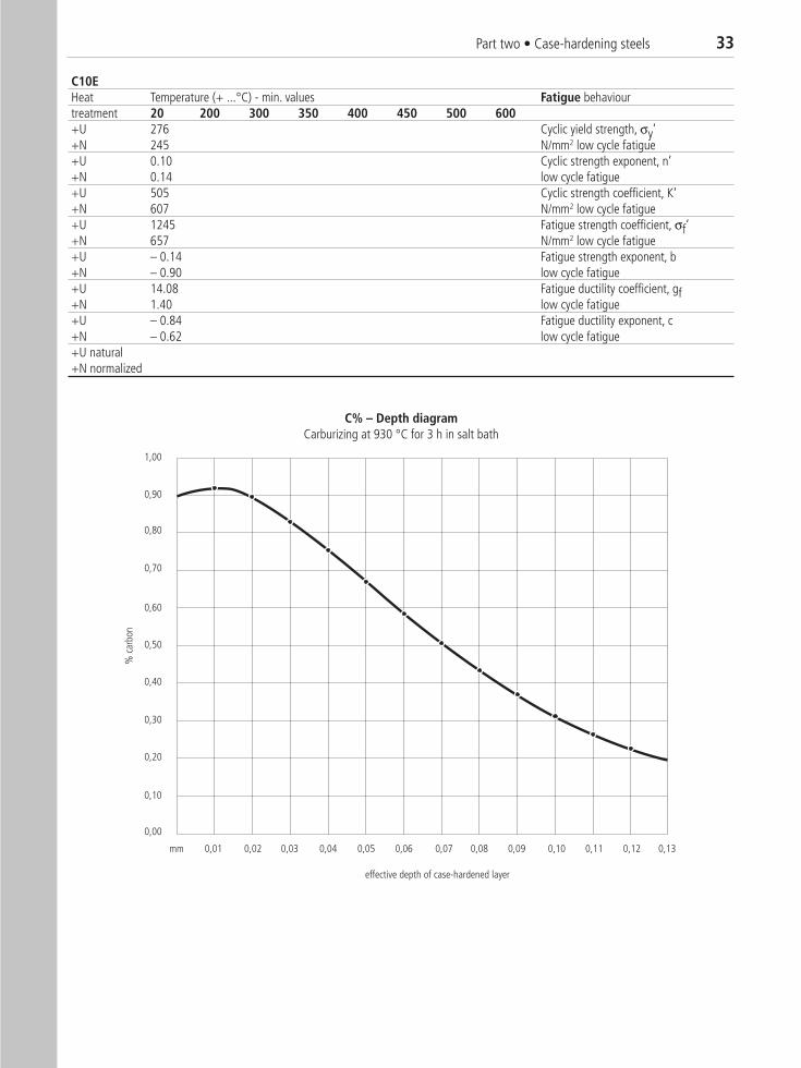
C10EHeat Temperature (+ ...°C) - min. values Fatigue behaviourtreatment 20 200 300 350 400 450 500 600+U 276 Cyclic yield strength, σy’+N 245 N/mm2 low cycle fatigue+U 0.10 Cyclic strength exponent, n’+N 0.14 low cycle fatigue+U 505 Cyclic strength coefficient, K‘+N 607 N/mm2 low cycle fatigue+U 1245 Fatigue strength coefficient, σf‘+N 657 N/mm2 low cycle fatigue+U – 0.14 Fatigue strength exponent, b+N – 0.90 low cycle fatigue+U 14.08 Fatigue ductility coefficient, gf+N 1.40 low cycle fatigue+U – 0.84 Fatigue ductility exponent, c+N – 0.62 low cycle fatigue+U natural+N normalized
1,00
0,90
0,80
0,70
0,60
0,50
0,40
0,30
0,20
0,10
0,00
0,01 0,02 0,03 0,04 0,05 0,06 0,07 0,08 0,09 0,10 0,11 0,12 0,13
effective depth of case-hardened layer
% c
arbo
n
mm
C% – Depth diagramCarburizing at 930 °C for 3 h in salt bath
34 Part two • Case-hardening steelsC1
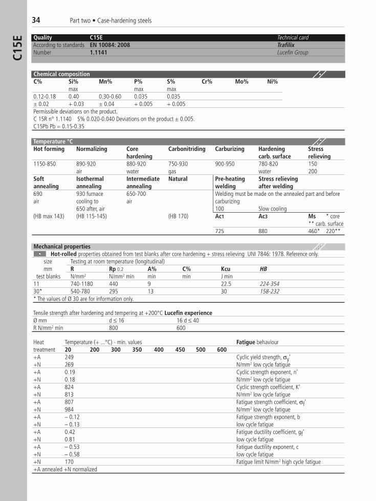
5EQuality C15E Technical cardAccording to standards EN 10084: 2008 TrafilixNumber 1.1141 Lucefin Group
Chemical compositionC% Si% Mn% P% S% Cr% Mo% Ni%
max max max0.12-0.18 0.40 0.30-0.60 0.035 0.035± 0.02 + 0.03 ± 0.04 + 0.005 + 0.005Permissible deviations on the product.C 15R n° 1.1140 S% 0.020-0.040 Deviations on the product ± 0.005.C15Pb Pb = 0.15-0.35
Temperature °CHot forming Normalizing Core Carbonitriding Carburizing Hardening Stress
hardening carb. surface relieving1150-850 890-920 880-920 750-930 900-950 780-820 150
air water gas water 200Soft Isothermal Intermediate Natural Pre-heating Stress relievingannealing annealing annealing welding after welding690 930 furnace 650-700 Welding must be made on the annealed part and beforeair cooling to air carburizing
650 after, air 100 Slow cooling(HB max 143) (HB 115-145) (HB 170) Ac1 Ac3 Ms * core
** carb. surface725 880 460* 220**
Mechanical propertiesHot-rolled properties obtained from test blanks after core hardening + stress relieving UNI 7846: 1978. Reference only.
size Testing at room temperature (longitudinal)mm R Rp 0.2 A% C% Kcu HB
test blanks N/mm2 N/mm2 min min min J min11 740-1180 440 9 22.5 224-35430* 540-780 295 13 30 158-232* The values of Ø 30 are for information only.
Tensile strength after hardening and tempering at +200°C Lucefin experienceØ mm d ≤ 16 16 d ≤ 40R N/mm2 min 800 600
Heat Temperature (+ ...°C) - min. values Fatigue behaviourtreatment 20 200 300 350 400 450 500 600+A 249 Cyclic yield strength, σy’+N 269 N/mm2 low cycle fatigue+A 0.19 Cyclic strength exponent, n’+N 0.18 N/mm2 low cycle fatigue+A 824 Cyclic strength coefficient, K‘+N 813 N/mm2 low cycle fatigue+A 807 Fatigue strength coefficient, σf‘+N 984 N/mm2 low cycle fatigue+A – 0.12 Fatigue strength exponent, b+N – 0.13 low cycle fatigue+A 0.42 Fatigue ductility coefficient, gf‘+N 0.81 low cycle fatigue+A – 0.53 Fatigue ductility exponent, c +N – 0.58 low cycle fatigue+N 170 Fatigue limit N/mm2 high cycle fatigue+A annealed +N normalized
Part two • Case-hardening steels 35
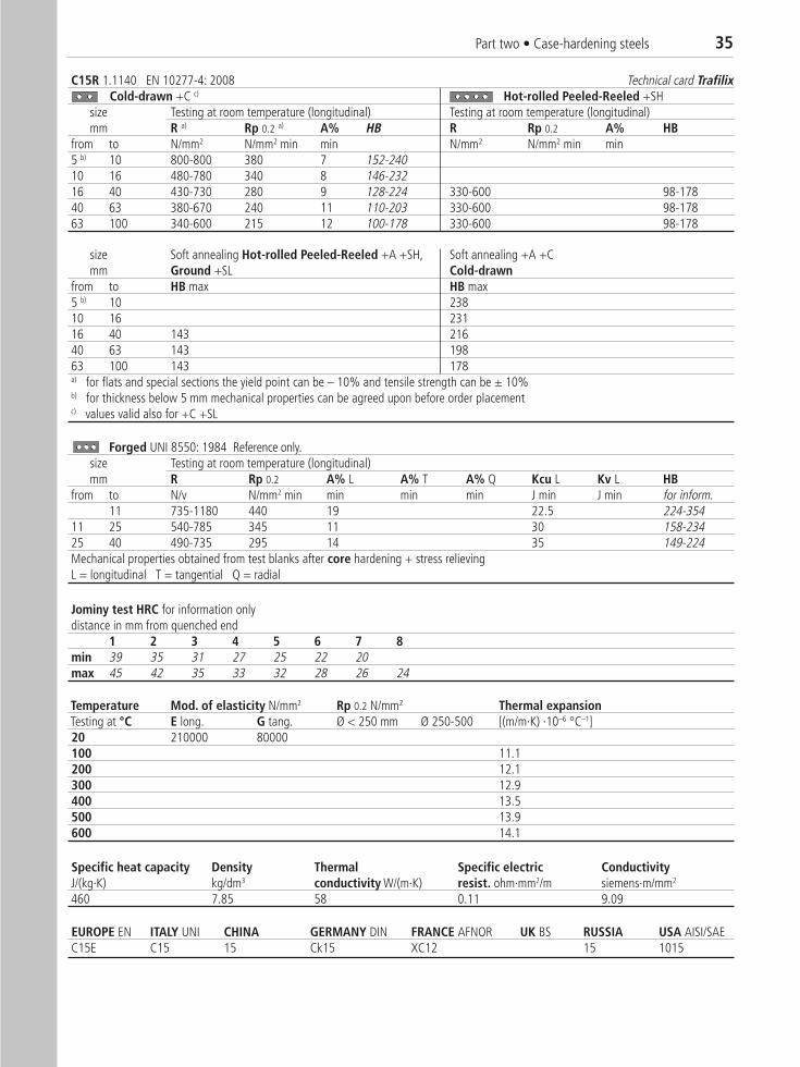
C15R 1.1140 EN 10277-4: 2008 Technical card TrafilixCold-drawn +C c) Hot-rolled Peeled-Reeled +SH �
size Testing at room temperature (longitudinal) Testing at room temperature (longitudinal)mm R a) Rp 0.2 a) A% HB R Rp 0.2 A% HB
from to N/mm2 N/mm2 min min N/mm2 N/mm2 min min5 b) 10 800-800 380 7 152-24010 16 480-780 340 8 146-23216 40 430-730 280 9 128-224 330-600 98-17840 63 380-670 240 11 110-203 330-600 98-17863 100 340-600 215 12 100-178 330-600 98-178
size Soft annealing Hot-rolled Peeled-Reeled +A +SH, Soft annealing +A +Cmm Ground +SL Cold-drawn
from to HB max HB max5 b) 10 23810 16 23116 40 143 21640 63 143 19863 100 143 178a) for flats and special sections the yield point can be – 10% and tensile strength can be ± 10%b) for thickness below 5 mm mechanical properties can be agreed upon before order placementc) values valid also for +C +SL
Forged UNI 8550: 1984 Reference only.size Testing at room temperature (longitudinal)mm R Rp 0.2 A% L A% T A% Q Kcu L Kv L HB
from to N/v N/mm2 min min min min J min J min for inform.11 735-1180 440 19 22.5 224-354
11 25 540-785 345 11 30 158-23425 40 490-735 295 14 35 149-224Mechanical properties obtained from test blanks after core hardening + stress relievingL = longitudinal T = tangential Q = radial
Jominy test HRC for information onlydistance in mm from quenched end
1 2 3 4 5 6 7 8min 39 35 31 27 25 22 20max 45 42 35 33 32 28 26 24
Specific heat capacity Density Thermal Specific electric ConductivityJ/(kg·K) kg/dm3 conductivity W/(m·K) resist. ohm·mm2/m siemens·m/mm2
460 7.85 58 0.11 9.09
Temperature Mod. of elasticity N/mm2 Rp 0.2 N/mm2 Thermal expansionTesting at °C E long. G tang. Ø < 250 mm Ø 250-500 [(m/m·K) ·10–6 °C–1]20 210000 80000100 11.1200 12.1300 12.9400 13.5500 13.9600 14.1
EUROPE EN ITALY UNI CHINA GERMANY DIN FRANCE AFNOR UK BS RUSSIA USA AISI/SAE C15E C15 15 Ck15 XC12 15 1015
36 Part two • Case-hardening steelsC1
6E
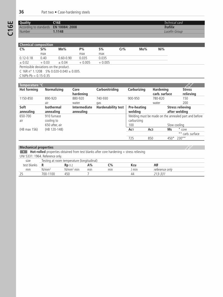
Quality C16E Technical cardAccording to standards EN 10084: 2008 TrafilixNumber 1.1148 Lucefin Group
Chemical compositionC% Si% Mn% P% S% Cr% Mo% Ni%
max max max0.12-0.18 0.40 0.60-0.90 0.035 0.035± 0.02 + 0.03 ± 0.04 + 0.005 + 0.005Permissible deviations on the product.C 16R n° 1.1208 S% 0.020-0.040 ± 0.005.C16Pb Pb = 0.15-0.35
Temperature °CHot forming Normalizing Core Carbonitriding Carburizing Hardening Stress
hardening carb. surface relieving1150-850 890-920 880-920 740-930 900-950 780-820 150
air water gas water 200Soft Isothermal Intermediate Hardenability test Pre-heating Stress relievingannealing annealing annealing welding after welding650-700 910 furnace Welding must be made on the annealed part and beforeair cooling to carburizing
650 after, air 100 Slow cooling(HB max 156) (HB 120-148) Ac1 Ac3 Ms * core
** carb. surface725 850 450* 230**
Mechanical propertiesHot-rolled properties obtained from test blanks after core hardening + stress relieving
UNI 5331: 1964. Reference only.size Testing at room temperature (longitudinal)
test blanks R Rp 0.2 A% C% Kcu HBmm N/mm2 N/mm2 min min min J min reference only
25 700-1100 450 7 44 213-331
Part two • Case-hardening steels 37
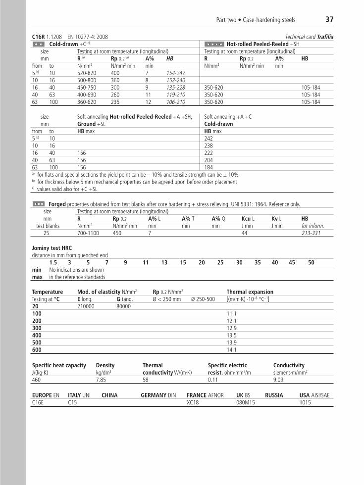
C16R 1.1208 EN 10277-4: 2008 Technical card TrafilixCold-drawn +C c) Hot-rolled Peeled-Reeled +SH �
size Testing at room temperature (longitudinal) Testing at room temperature (longitudinal)mm R a) Rp 0.2 a) A% HB R Rp 0.2 A% HB
from to N/mm2 N/mm2 min min N/mm2 N/mm2 min min5 b) 10 520-820 400 7 154-24710 16 500-800 360 8 152-24016 40 450-750 300 9 135-228 350-620 105-18440 63 400-690 260 11 119-210 350-620 105-18463 100 360-620 235 12 106-210 350-620 105-184
size Soft annealing Hot-rolled Peeled-Reeled +A +SH, Soft annealing +A +Cmm Ground +SL Cold-drawn
from to HB max HB max5 b) 10 24210 16 23816 40 156 22240 63 156 20463 100 156 184a) for flats and special sections the yield point can be – 10% and tensile strength can be ± 10%b) for thickness below 5 mm mechanical properties can be agreed upon before order placementc) values valid also for +C +SL
Forged properties obtained from test blanks after core hardening + stress relieving UNI 5331: 1964. Reference only.size Testing at room temperature (longitudinal)mm R Rp 0.2 A% L A% T A% Q Kcu L Kv L HB
test blanks N/mm2 N/mm2 min min min min J min J min for inform.25 700-1100 450 7 44 213-331
Jominy test HRCdistance in mm from quenched end
1.5 3 5 7 9 11 13 15 20 25 30 35 40 45 50min No indications are shown max in the reference standards
Specific heat capacity Density Thermal Specific electric ConductivityJ/(kg·K) kg/dm3 conductivity W/(m·K) resist. ohm·mm2/m siemens·m/mm2
460 7.85 58 0.11 9.09
Temperature Mod. of elasticity N/mm2 Rp 0.2 N/mm2 Thermal expansionTesting at °C E long. G tang. Ø < 250 mm Ø 250-500 [(m/m·K) ·10–6 °C–1]20 210000 80000100 11.1200 12.1300 12.9400 13.5500 13.9600 14.1
EUROPE EN ITALY UNI CHINA GERMANY DIN FRANCE AFNOR UK BS RUSSIA USA AISI/SAE C16E C15 XC18 080M15 1015
38 Part two • Case-hardening steelsXC
18
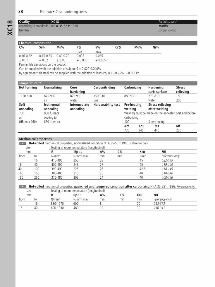
Quality XC18 Technical cardAccording to standards NF A 35-551: 1986 TrafilixNumber Lucefin Group
Chemical compositionC% Si% Mn% P% S% Cr% Mo% Ni%
max max0.16-0.22 0.15-0.35 0.40-0.70 0.035 0.035± 0.01 + 0.02 ± 0.03 + 0.005 + 0.005Permissible deviations on the product.Can be supplied with the addition of sulphur S = 0.020-0.040%By agreement this steel can be supplied with the addition of lead (Pb) 0.15-0.25% XC 18 Pb
Temperature °CHot forming Normalizing Core Carbonitriding Carburizing Hardening Stress
hardening carb. surface relieving1150-850 875-900 870-910 750-930 880-930 770-810 150
air water gas water 200Soft Isothermal Intermediate Hardenability test Pre-heating Stress relievingannealing annealing annealing welding after welding700 880 furnace Welding must be made on the annealed part and beforeair cooling to carburizing(HB max 160) 650 after, air 100 Slow cooling
Ac1 Ac3 Ms Mf730 845 440 220
Mechanical propertiesHot-rolled mechanical properties, normalized condition NF A 35-551: 1986. Reference only.
size Testing at room temperature (longitudinal)mm R Rp 0.2 A% C% Kcu HB
from to N/mm2 N/mm2 min min min J min reference only16 410-490 255 28 45 122-149
16 40 400-490 245 27 45 119-14940 100 390-490 225 26 42.5 114-149100 160 380-480 215 25 40 110-146160 250 370-480 205 24 40 108-146
Hot-rolled mechanical properties, quenched and tempered condition after carburizing NF A 35-551: 1986. Reference only.size Testing at room temperature (longitudinal)mm R Rp 0.2 A% C% Kcu HB
from to N/mm2 N/mm2 min min min min reference only16 880-1270 600 8 20 263-373
16 40 690-1030 480 12 30 210-311
Part two • Case-hardening steels 39
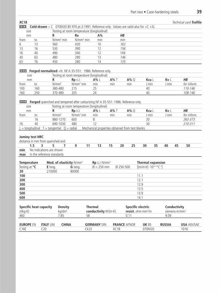
XC18 Technical card TrafilixCold-drawn + C 070M20 BS 970 pt.3:1991. Reference only. Values are valid also for +C +SL
size Testing at room temperature (longitudinal)mm R Re A% HB
from to N/mm2 min N/mm2 min min min6 13 560 420 10 16213 16 530 390 12 15616 40 490 340 12 14940 63 480 290 13 14663 76 450 280 14 135
Forged normalized +N NF A 35-551: 1986. Reference only.size Testing at room temperature (longitudinal)mm R Rp 0.2 A% L A% T A% Q Kcu L Kv L HB
from to N/mm2 N/mm2 min min min min J min J min for inform.100 160 380-480 215 25 40 110-146160 250 370-480 205 24 40 108-146
Forged quenched and tempered after carburizing NF A 35-551: 1986. Reference only.size Testing at room temperature (longitudinal)mm R Rp 0.2 A% L A% T A% Q Kcu L Kv L HB
from to N/mm2 N/mm2 min min min min J min J min for inform.16 880-1270 600 8 20 263-373
16 40 690-1030 480 12 30 210-311L = longitudinal T = tangential Q = radial Mechanical properties obtained from test blanks
Jominy test HRCdistance in mm from quenched end
1.5 3 5 7 9 11 13 15 20 25 30 35 40 45 50min No indications are shownmax in the reference standards
Specific heat capacity Density Thermal Specific electric ConductivityJ/(kg·K) kg/dm3 conductivity W/(m·K) resist. ohm·mm2/m siemens·m/mm2
460 7.85 58 0.11 9.09
Temperature Mod. of elasticity N/mm2 Rp 0.2 N/mm2 Thermal expansionTesting at °C E long. G tang. Ø < 250 mm Ø 250-500 [(m/m·K) ·10–6 °C–1]20 210000 80000100 11.1200 12.1300 12.9400 13.5500 13.9600 14.1
EUROPE EN ITALY UNI CHINA GERMANY DIN FRANCE AFNOR UK BS RUSSIA USA AISI/SAE C16E C20 Ck22 XC18 070M20 1016
40 Part two • Case-hardening steels16
MnC
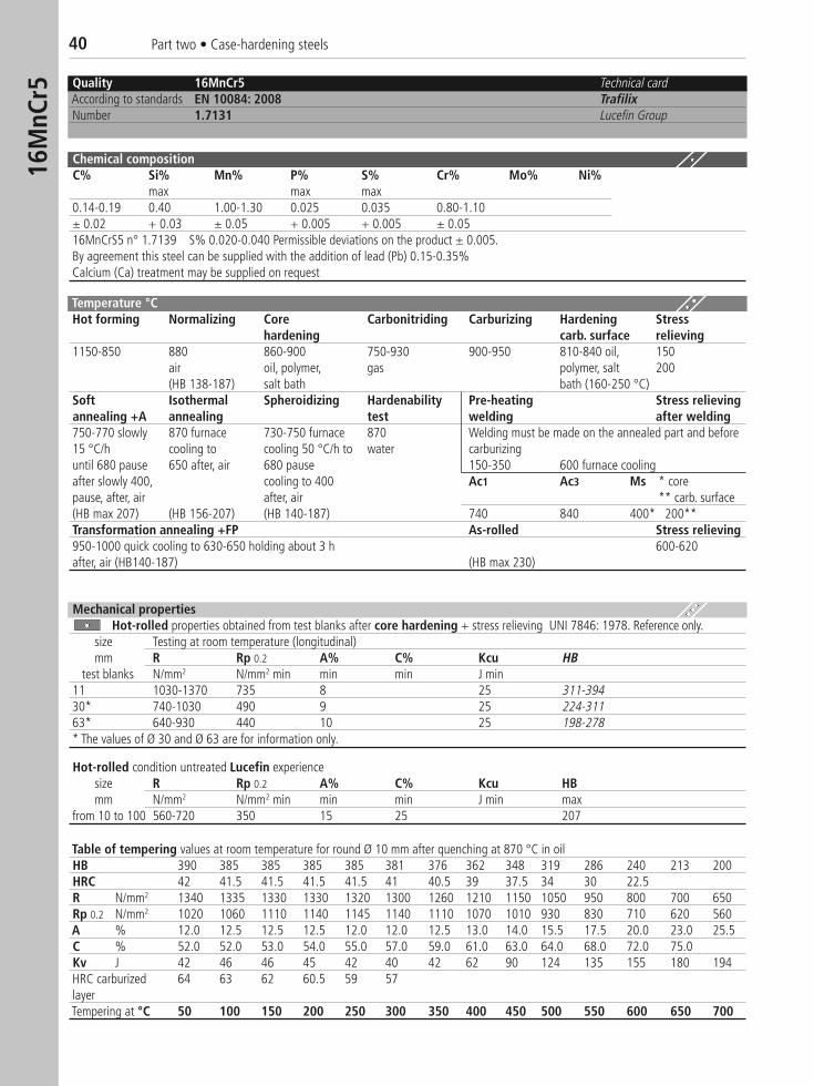
r5 Quality 16MnCr5 Technical cardAccording to standards EN 10084: 2008 TrafilixNumber 1.7131 Lucefin Group
Chemical compositionC% Si% Mn% P% S% Cr% Mo% Ni%
max max max0.14-0.19 0.40 1.00-1.30 0.025 0.035 0.80-1.10± 0.02 + 0.03 ± 0.05 + 0.005 + 0.005 ± 0.0516MnCrS5 n° 1.7139 S% 0.020-0.040 Permissible deviations on the product ± 0.005.By agreement this steel can be supplied with the addition of lead (Pb) 0.15-0.35% Calcium (Ca) treatment may be supplied on request
Temperature °CHot forming Normalizing Core Carbonitriding Carburizing Hardening Stress
hardening carb. surface relieving1150-850 880 860-900 750-930 900-950 810-840 oil, 150
air oil, polymer, gas polymer, salt 200(HB 138-187) salt bath bath (160-250 °C)
Soft Isothermal Spheroidizing Hardenability Pre-heating Stress relievingannealing +A annealing test welding after welding750-770 slowly 870 furnace 730-750 furnace 870 Welding must be made on the annealed part and before15 °C/h cooling to cooling 50 °C/h to water carburizinguntil 680 pause 650 after, air 680 pause 150-350 600 furnace coolingafter slowly 400, cooling to 400 Ac1 Ac3 Ms * corepause, after, air after, air ** carb. surface(HB max 207) (HB 156-207) (HB 140-187) 740 840 400* 200**Transformation annealing +FP As-rolled Stress relieving950-1000 quick cooling to 630-650 holding about 3 h 600-620after, air (HB140-187) (HB max 230)
Hot-rolled condition untreated Lucefin experiencesize R Rp 0.2 A% C% Kcu HB mm N/mm2 N/mm2 min min min J min max
from 10 to 100 560-720 350 15 25 207
Table of tempering values at room temperature for round Ø 10 mm after quenching at 870 °C in oilHB 390 385 385 385 385 381 376 362 348 319 286 240 213 200HRC 42 41.5 41.5 41.5 41.5 41 40.5 39 37.5 34 30 22.5R N/mm2 1340 1335 1330 1330 1320 1300 1260 1210 1150 1050 950 800 700 650Rp 0.2 N/mm2 1020 1060 1110 1140 1145 1140 1110 1070 1010 930 830 710 620 560A % 12.0 12.5 12.5 12.5 12.0 12.0 12.5 13.0 14.0 15.5 17.5 20.0 23.0 25.5C % 52.0 52.0 53.0 54.0 55.0 57.0 59.0 61.0 63.0 64.0 68.0 72.0 75.0Kv J 42 46 46 45 42 40 42 62 90 124 135 155 180 194HRC carburized 64 63 62 60.5 59 57layerTempering at °C 50 100 150 200 250 300 350 400 450 500 550 600 650 700
Mechanical propertiesHot-rolled properties obtained from test blanks after core hardening + stress relieving UNI 7846: 1978. Reference only.
size Testing at room temperature (longitudinal) mm R Rp 0.2 A% C% Kcu HB
test blanks N/mm2 N/mm2 min min min J min11 1030-1370 735 8 25 311-39430* 740-1030 490 9 25 224-31163* 640-930 440 10 25 198-278* The values of Ø 30 and Ø 63 are for information only.
Part two • Case-hardening steels 41
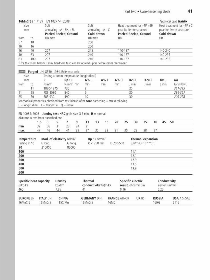
16MnCrS5 1.7139 EN 10277-4: 2008 Technical card Trafilixsize Soft Soft Heat treatment for +FP +SH Heat treatment for +FP +Cmm annealing +A +SH, +SL annealing +A +C pearlite-ferrite structure pearlite-ferrite structure
Peeled-Reeled, Ground Cold-drawn Peeled-Reeled, Ground Cold-drawnfrom to HB max HB max HB HB 5 a) 10 26010 16 25016 40 207 245 140-187 140-24040 63 207 240 140-187 140-23563 100 207 240 140-187 140-235a) for thickness below 5 mm, hardness test, can be agreed upon before order placement
Forged UNI 8550: 1984. Reference only.size Testing at room temperature (longitudinal)mm R Rp 0.2 A% L A% T A% Q Kcu L Kcu T Kv L HB
from to N/mm2 N/mm2 min min min min J min J min J min for inform.11 1030-1375 735 8 25 311-395
11 25 785-1080 540 9 30 234-32725 50 685-930 490 10 30 209-278Mechanical properties obtained from test blanks after core hardening + stress relievingL = longitudinal T = tangential Q = radial
EN 10084: 2008 Jominy test HRC grain size G 5 min. H = normaldistance in mm from quenched end
1.5 3 5 7 9 11 13 15 20 25 30 35 40 45 50min 39 36 31 28 24 21max 47 46 44 41 39 37 35 33 31 30 29 28 27
Specific heat capacity Density Thermal Specific electric ConductivityJ/(kg·K) kg/dm3 conductivity W/(m·K) resist. ohm·mm2/m siemens·m/mm2
460 7.85 41 0.16 6.25
Temperature Mod. of elasticity N/mm2 Rp 0.2 N/mm2 Thermal expansionTesting at °C E long. G tang. Ø < 250 mm Ø 250-500 [(m/m·K) ·10–6 °C–1]20 210000 80000100 11.1200 12.1300 12.9400 13.5500 13.9600
EUROPE EN ITALY UNI CHINA GERMANY DIN FRANCE AFNOR UK BS RUSSIA USA AISI/SAE16MnCr5 16MnCr5 15CrMn 16MnCr5 16MC 16HG 5115
42 Part two • Case-hardening steels20
MnC
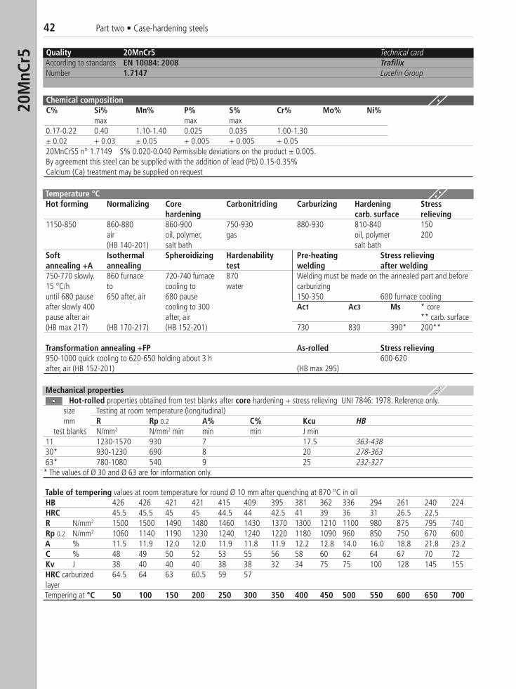
r5 Quality 20MnCr5 Technical cardAccording to standards EN 10084: 2008 TrafilixNumber 1.7147 Lucefin Group
Chemical compositionC% Si% Mn% P% S% Cr% Mo% Ni%
max max max0.17-0.22 0.40 1.10-1.40 0.025 0.035 1.00-1.30± 0.02 + 0.03 ± 0.05 + 0.005 + 0.005 + 0.0520MnCrS5 n° 1.7149 S% 0.020-0.040 Permissible deviations on the product ± 0.005.By agreement this steel can be supplied with the addition of lead (Pb) 0.15-0.35% Calcium (Ca) treatment may be supplied on request
Table of tempering values at room temperature for round Ø 10 mm after quenching at 870 °C in oilHB 426 426 421 421 415 409 395 381 362 336 294 261 240 224HRC 45.5 45.5 45 45 44.5 44 42.5 41 39 36 31 26.5 22.5R N/mm2 1500 1500 1490 1480 1460 1430 1370 1300 1210 1100 980 875 795 740Rp 0.2 N/mm2 1060 1140 1190 1230 1240 1240 1220 1180 1090 960 850 750 670 600A % 11.5 11.9 12.0 12.0 11.9 11.8 11.9 12.2 12.8 14.0 16.0 18.8 21.8 23.2C % 48 49 50 52 53 55 56 58 60 62 64 67 70 72Kv J 38 40 40 40 38 38 32 34 75 75 100 128 145 155HRC carburized 64.5 64 63 60.5 59 57layerTempering at °C 50 100 150 200 250 300 350 400 450 500 550 600 650 700
Temperature °CHot forming Normalizing Core Carbonitriding Carburizing Hardening Stress
hardening carb. surface relieving1150-850 860-880 860-900 750-930 880-930 810-840 150
air oil, polymer, gas oil, polymer 200(HB 140-201) salt bath salt bath
Soft Isothermal Spheroidizing Hardenability Pre-heating Stress relievingannealing +A annealing test welding after welding750-770 slowly. 860 furnace 720-740 furnace 870 Welding must be made on the annealed part and before15 °C/h to cooling to water carburizinguntil 680 pause 650 after, air 680 pause 150-350 600 furnace coolingafter slowly 400 cooling to 300 Ac1 Ac3 Ms * corepause after air after, air ** carb. surface(HB max 217) (HB 170-217) (HB 152-201) 730 830 390* 200**
Transformation annealing +FP As-rolled Stress relieving950-1000 quick cooling to 620-650 holding about 3 h 600-620after, air (HB 152-201) (HB max 295)
Mechanical propertiesHot-rolled properties obtained from test blanks after core hardening + stress relieving UNI 7846: 1978. Reference only.
size Testing at room temperature (longitudinal) mm R Rp 0.2 A% C% Kcu HB
test blanks N/mm2 N/mm2 min min min J min11 1230-1570 930 7 17.5 363-43830* 930-1230 690 8 20 278-36363* 780-1080 540 9 25 232-327
* The values of Ø 30 and Ø 63 are for information only.
Part two • Case-hardening steels 43
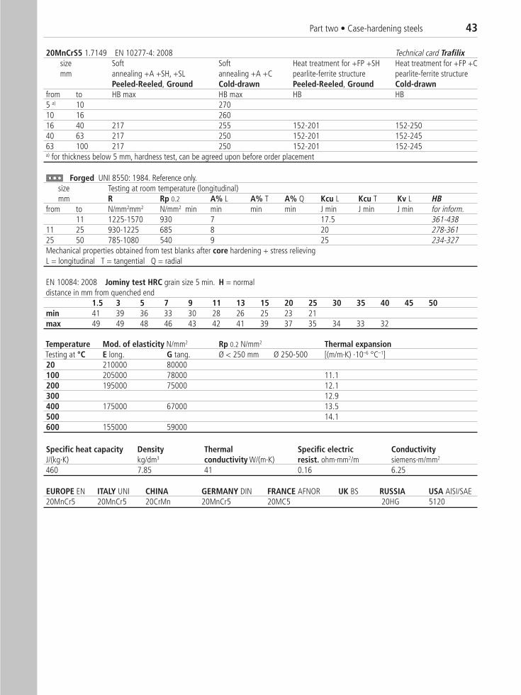
20MnCrS5 1.7149 EN 10277-4: 2008 Technical card Trafilixsize Soft Soft Heat treatment for +FP +SH Heat treatment for +FP +Cmm annealing +A +SH, +SL annealing +A +C pearlite-ferrite structure pearlite-ferrite structure
Peeled-Reeled, Ground Cold-drawn Peeled-Reeled, Ground Cold-drawnfrom to HB max HB max HB HB 5 a) 10 27010 16 26016 40 217 255 152-201 152-25040 63 217 250 152-201 152-24563 100 217 250 152-201 152-245a) for thickness below 5 mm, hardness test, can be agreed upon before order placement
Forged UNI 8550: 1984. Reference only.size Testing at room temperature (longitudinal)mm R Rp 0.2 A% L A% T A% Q Kcu L Kcu T Kv L HB
from to N/mm2mm2 N/mm2 min min min min J min J min J min for inform.11 1225-1570 930 7 17.5 361-438
11 25 930-1225 685 8 20 278-36125 50 785-1080 540 9 25 234-327Mechanical properties obtained from test blanks after core hardening + stress relievingL = longitudinal T = tangential Q = radial
EN 10084: 2008 Jominy test HRC grain size 5 min. H = normaldistance in mm from quenched end
1.5 3 5 7 9 11 13 15 20 25 30 35 40 45 50min 41 39 36 33 30 28 26 25 23 21max 49 49 48 46 43 42 41 39 37 35 34 33 32
Specific heat capacity Density Thermal Specific electric ConductivityJ/(kg·K) kg/dm3 conductivity W/(m·K) resist. ohm·mm2/m siemens·m/mm2
460 7.85 41 0.16 6.25
Temperature Mod. of elasticity N/mm2 Rp 0.2 N/mm2 Thermal expansionTesting at °C E long. G tang. Ø < 250 mm Ø 250-500 [(m/m·K) ·10–6 °C–1]20 210000 80000100 205000 78000 11.1200 195000 75000 12.1300 12.9400 175000 67000 13.5500 14.1600 155000 59000
EUROPE EN ITALY UNI CHINA GERMANY DIN FRANCE AFNOR UK BS RUSSIA USA AISI/SAE20MnCr5 20MnCr5 20CrMn 20MnCr5 20MC5 20HG 5120
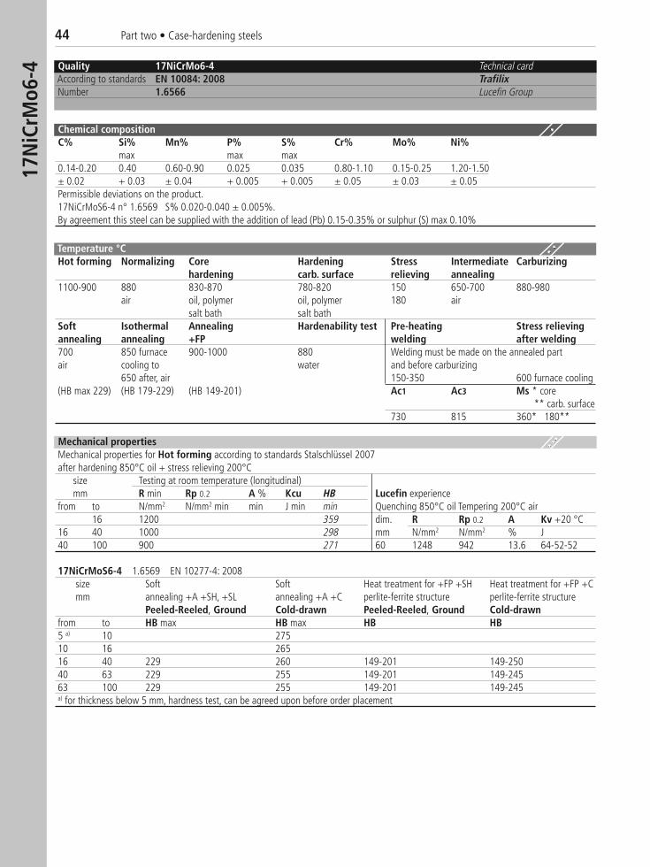
44 Part two • Case-hardening steels17
NiC
rMo6
-4 Quality 17NiCrMo6-4 Technical cardAccording to standards EN 10084: 2008 TrafilixNumber 1.6566 Lucefin Group
Chemical compositionC% Si% Mn% P% S% Cr% Mo% Ni%
max max max0.14-0.20 0.40 0.60-0.90 0.025 0.035 0.80-1.10 0.15-0.25 1.20-1.50± 0.02 + 0.03 ± 0.04 + 0.005 + 0.005 ± 0.05 ± 0.03 ± 0.05Permissible deviations on the product.17NiCrMoS6-4 n° 1.6569 S% 0.020-0.040 ± 0.005%.By agreement this steel can be supplied with the addition of lead (Pb) 0.15-0.35% or sulphur (S) max 0.10%
Temperature °CHot forming Normalizing Core Hardening Stress Intermediate Carburizing
hardening carb. surface relieving annealing1100-900 880 830-870 780-820 150 650-700 880-980
air oil, polymer oil, polymer 180 airsalt bath salt bath
Soft Isothermal Annealing Hardenability test Pre-heating Stress relievingannealing annealing +FP welding after welding700 850 furnace 900-1000 880 Welding must be made on the annealed part air cooling to water and before carburizing
650 after, air 150-350 600 furnace cooling(HB max 229) (HB 179-229) (HB 149-201) Ac1 Ac3 Ms * core
** carb. surface730 815 360* 180**
17NiCrMoS6-4 1.6569 EN 10277-4: 2008size Soft Soft Heat treatment for +FP +SH Heat treatment for +FP +Cmm annealing +A +SH, +SL annealing +A +C perlite-ferrite structure perlite-ferrite structure
Peeled-Reeled, Ground Cold-drawn Peeled-Reeled, Ground Cold-drawnfrom to HB max HB max HB HB5 a) 10 27510 16 26516 40 229 260 149-201 149-25040 63 229 255 149-201 149-24563 100 229 255 149-201 149-245a) for thickness below 5 mm, hardness test, can be agreed upon before order placement
Mechanical propertiesMechanical properties for Hot forming according to standards Stalschlüssel 2007after hardening 850°C oil + stress relieving 200°C
size Testing at room temperature (longitudinal)mm R min Rp 0.2 A % Kcu HB Lucefin experience
from to N/mm2 N/mm2 min min J min min Quenching 850°C oil Tempering 200°C air16 1200 359 dim. R Rp 0.2 A Kv +20 °C
16 40 1000 298 mm N/mm2 N/mm2 % J40 100 900 271 60 1248 942 13.6 64-52-52
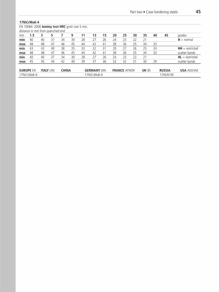
Part two • Case-hardening steels 45
EUROPE EN ITALY UNI CHINA GERMANY DIN FRANCE AFNOR UK BS RUSSIA USA AISI/SAE 17NiCrMo6-4 17NiCrMo6-4 17HGN1M
17NiCrMo6-4EN 10084: 2008 Jominy test HRC grain size 5 min.distance in mm from quenched endmm 1.5 3 5 7 9 11 13 15 20 25 30 35 40 45 gradesmin 40 40 37 34 30 28 27 26 24 23 22 21 H = normalmax 48 48 47 46 45 44 42 41 38 36 35 34 33min 43 43 40 38 35 33 32 31 29 27 26 25 24 HH = restrictedmax 48 48 47 46 45 44 42 41 38 36 35 34 33 scatter bandsmin 40 40 37 34 30 28 27 26 24 23 22 21 HL = restrictedmax 45 45 44 42 40 39 37 36 33 32 31 30 29 scatter bands
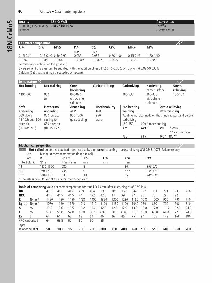
46 Part two • Case-hardening steels18
NiC
rMo5
Quality 18NiCrMo5 Technical cardAccording to standards UNI 7846: 1978 TrafilixNumber Lucefin Group
Chemical compositionC% Si% Mn% P% S% Cr% Mo% Ni%
max max0.15-0.21 0.15-0.40 0.60-0.90 0.035 0.035 0.70-1.00 0.15-0.25 1.20-1.50± 0.02 ± 0.03 ± 0.04 + 0.005 + 0.005 ± 0.05 ± 0.03 ± 0.05Permissible deviations on the product.By agreement this steel can be supplied with the addition of lead (Pb) 0.15-0.35% or sulphur (S) 0.020-0.035% Calcium (Ca) treatment may be supplied on request
Temperature °CHot forming Normalizing Core Carbonitriding Carburizing Hardening Stress
hardening carb. surface relieving1100-900 880 840-870 880-930 800-830 150-180
air oil, polymer oil, polymersalt bath salt bath
Soft Isothermal Annealing Hardenability Pre-heating Stress relievingannealing annealing +FP test welding after welding700 slowly 850 furnace 950-1000 850 Welding must be made on the annealed part and before 15 °C/h until 600 cooling to quick cooling water carburizingafter, air 650 after, air 150-350 600 furnace cooling(HB max 240) (HB 150-220) Ac1 Ac3 Ms * core
** carb. surface730 815 360* 180**
Table of tempering values at room temperature for round Ø 10 mm after quenching at 850 °C in oil HB 415 415 415 409 404 395 381 362 344 327 301 271 237 218HRC 44.5 44.5 44.5 44 43.5 42.5 41 39 37 35 32 28 22R N/mm2 1460 1460 1450 1430 1400 1360 1300 1230 1150 1080 1000 900 790 710Rp 0.2 N/mm2 1070 1120 1170 1210 1210 1190 1150 1100 1040 960 860 790 700 610A % 13.5 13.6 13.5 13.2 13.0 12.8 12.8 12.9 13.8 15.0 17.0 19.5 22.0 24.0C % 57.0 58.0 59.0 60.0 60.0 60.0 60.0 60.0 61.0 63.0 65.0 68.0 72.0 74.0Kv J 64 64 62 62 64 46 46 46 75 94 125 148 166 180HRC carburized 64 63.5 62 60 59 56layerTempering at °C 50 100 150 200 250 300 350 400 450 500 550 600 650 700
Mechanical propertiesHot-rolled properties obtained from test blanks after core hardening + stress relieving UNI 7846: 1978. Reference only.
size Testing at room temperature (longitudinal) mm R Rp 0.2 A% C% Kcu HB
test blanks N/mm2 N/mm2 min min min J min11 1230-1520 980 8 30 363-43230* 980-1270 735 9 32.5 295-37363* 830-1130 635 10 35 249-339* The values of Ø 30 and Ø 63 are for information only.
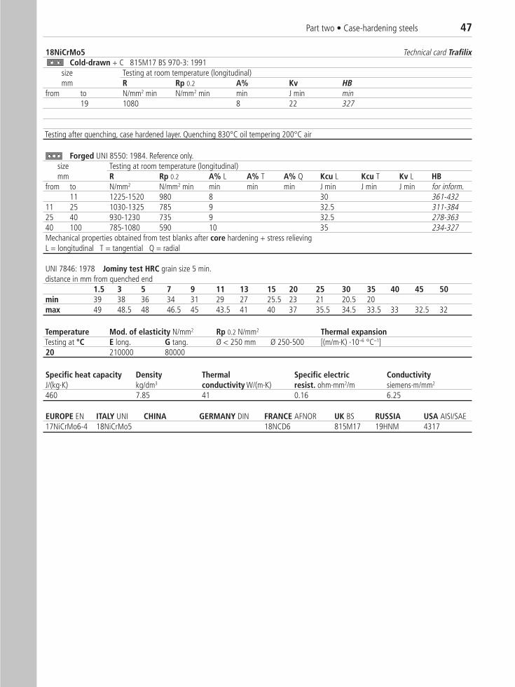
Part two • Case-hardening steels 47
18NiCrMo5 Technical card TrafilixCold-drawn + C 815M17 BS 970-3: 1991
size Testing at room temperature (longitudinal)mm R Rp 0.2 A% Kv HB
from to N/mm2 min N/mm2 min min J min min19 1080 8 22 327
Testing after quenching, case hardened layer. Quenching 830°C oil tempering 200°C air
Forged UNI 8550: 1984. Reference only.size Testing at room temperature (longitudinal)mm R Rp 0.2 A% L A% T A% Q Kcu L Kcu T Kv L HB
from to N/mm2 N/mm2 min min min min J min J min J min for inform.11 1225-1520 980 8 30 361-432
11 25 1030-1325 785 9 32.5 311-38425 40 930-1230 735 9 32.5 278-36340 100 785-1080 590 10 35 234-327Mechanical properties obtained from test blanks after core hardening + stress relievingL = longitudinal T = tangential Q = radial
Temperature Mod. of elasticity N/mm2 Rp 0.2 N/mm2 Thermal expansionTesting at °C E long. G tang. Ø < 250 mm Ø 250-500 [(m/m·K) ·10–6 °C–1]20 210000 80000
Specific heat capacity Density Thermal Specific electric ConductivityJ/(kg·K) kg/dm3 conductivity W/(m·K) resist. ohm·mm2/m siemens·m/mm2
460 7.85 41 0.16 6.25
EUROPE EN ITALY UNI CHINA GERMANY DIN FRANCE AFNOR UK BS RUSSIA USA AISI/SAE 17NiCrMo6-4 18NiCrMo5 18NCD6 815M17 19HNM 4317
UNI 7846: 1978 Jominy test HRC grain size 5 min.distance in mm from quenched end
1.5 3 5 7 9 11 13 15 20 25 30 35 40 45 50min 39 38 36 34 31 29 27 25.5 23 21 20.5 20max 49 48.5 48 46.5 45 43.5 41 40 37 35.5 34.5 33.5 33 32.5 32
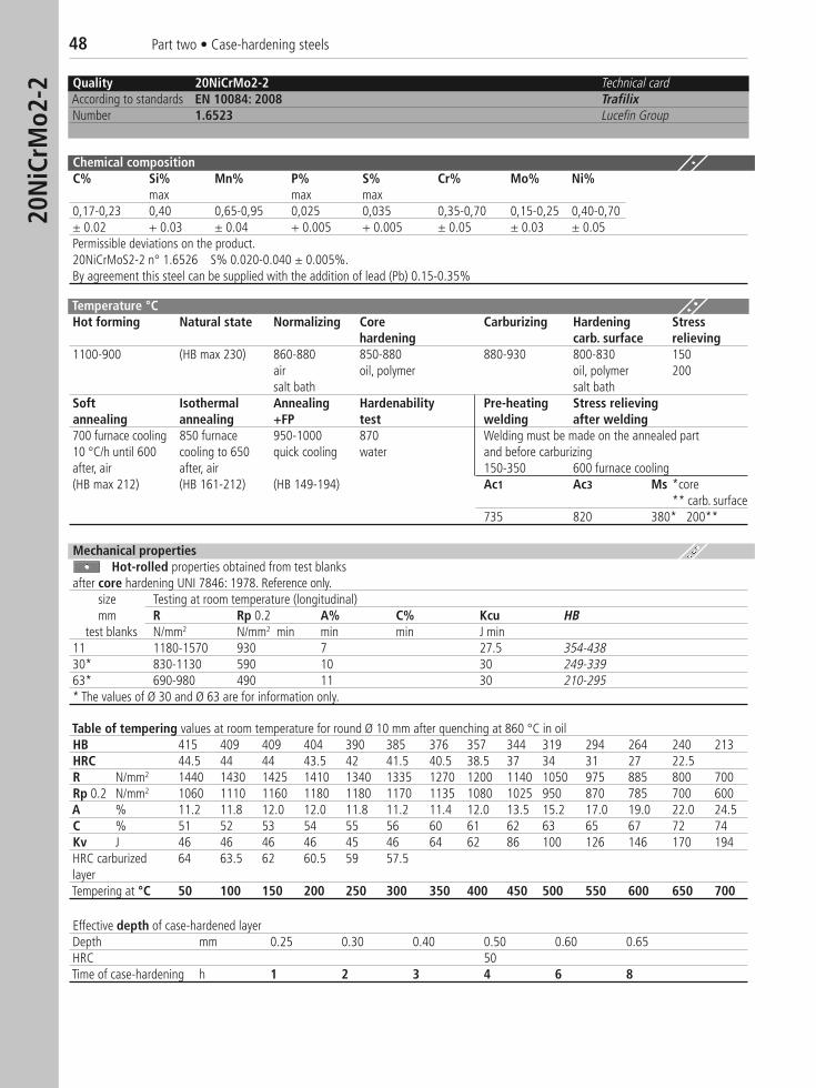
48 Part two • Case-hardening steels20
NiC
rMo2
-2 Quality 20NiCrMo2-2 Technical cardAccording to standards EN 10084: 2008 TrafilixNumber 1.6523 Lucefin Group
Chemical compositionC% Si% Mn% P% S% Cr% Mo% Ni%
max max max0,17-0,23 0,40 0,65-0,95 0,025 0,035 0,35-0,70 0,15-0,25 0,40-0,70± 0.02 + 0.03 ± 0.04 + 0.005 + 0.005 ± 0.05 ± 0.03 ± 0.05Permissible deviations on the product.20NiCrMoS2-2 n° 1.6526 S% 0.020-0.040 ± 0.005%.By agreement this steel can be supplied with the addition of lead (Pb) 0.15-0.35%
Temperature °CHot forming Natural state Normalizing Core Carburizing Hardening Stress
hardening carb. surface relieving1100-900 (HB max 230) 860-880 850-880 880-930 800-830 150
air oil, polymer oil, polymer 200salt bath salt bath
Soft Isothermal Annealing Hardenability Pre-heating Stress relievingannealing annealing +FP test welding after welding700 furnace cooling 850 furnace 950-1000 870 Welding must be made on the annealed part 10 °C/h until 600 cooling to 650 quick cooling water and before carburizingafter, air after, air 150-350 600 furnace cooling(HB max 212) (HB 161-212) (HB 149-194) Ac1 Ac3 Ms *core
** carb. surface735 820 380* 200**
Table of tempering values at room temperature for round Ø 10 mm after quenching at 860 °C in oilHB 415 409 409 404 390 385 376 357 344 319 294 264 240 213HRC 44.5 44 44 43.5 42 41.5 40.5 38.5 37 34 31 27 22.5R N/mm2 1440 1430 1425 1410 1340 1335 1270 1200 1140 1050 975 885 800 700Rp 0.2 N/mm2 1060 1110 1160 1180 1180 1170 1135 1080 1025 950 870 785 700 600A % 11.2 11.8 12.0 12.0 11.8 11.2 11.4 12.0 13.5 15.2 17.0 19.0 22.0 24.5C % 51 52 53 54 55 56 60 61 62 63 65 67 72 74Kv J 46 46 46 46 45 46 64 62 86 100 126 146 170 194HRC carburized 64 63.5 62 60.5 59 57.5layerTempering at °C 50 100 150 200 250 300 350 400 450 500 550 600 650 700
Effective depth of case-hardened layerDepth mm 0.25 0.30 0.40 0.50 0.60 0.65HRC 50Time of case-hardening h 1 2 3 4 6 8
Mechanical propertiesHot-rolled properties obtained from test blanks
after core hardening UNI 7846: 1978. Reference only.size Testing at room temperature (longitudinal) mm R Rp 0.2 A% C% Kcu HB
test blanks N/mm2 N/mm2 min min min J min11 1180-1570 930 7 27.5 354-43830* 830-1130 590 10 30 249-33963* 690-980 490 11 30 210-295* The values of Ø 30 and Ø 63 are for information only.
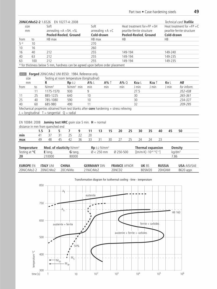
Part two • Case-hardening steels 49
20NiCrMoS2-2 1.6526 EN 10277-4: 2008 Technical card Trafilixsize Soft Soft Heat treatment for+FP +SH Heat treatment for +FP +Cmm annealing +A +SH, +SL annealing +A +C pearlite-ferrite structure pearlite-ferrite structure
Peeled-Reeled, Ground Cold-drawn Peeled-Reeled, Ground Cold-drawnfrom to HB max HB max HB HB 5 a) 10 27010 16 26016 40 212 255 149-194 149-24040 63 212 255 149-194 149-23563 100 212 255 149-194 149-235a) for thickness below 5 mm, hardness can be agreed upon before order placement
Forged 20NiCrMo2 UNI 8550: 1984. Reference only. size Testing at room temperature (longitudinal)mm R Rp 0.2 A% L A% T A% Q Kcu L Kcu T Kv L HB
from to N/mm2 N/mm2 min min min min J min J min J min for inform.11 1175-1570 930 9 27.5 352-438
11 25 885-1225 640 10 30 265-36125 40 785-1080 590 10 30 234-32740 60 685-980 490 11 32 209-295Mechanical properties obtained from test blanks after core hardening + stress relievingL = longitudinal T = tangential Q = radial
EN 10084: 2008 Jominy test HRC grain size 5 min. H = normaldistance in mm from quenched end
1.5 3 5 7 9 11 13 15 20 25 30 35 40 45 50min 41 37 31 25 22 20max 49 48 45 42 36 33 31 30 27 25 24 24 23
Temperature Mod. of elasticity N/mm2 Rp 0.2 N/mm2 Thermal expansion DensityTesting at °C E long. G tang. Ø < 250 mm Ø 250-500 [(m/m·K) ·10–6 °C–1] kg/dm3
20 210000 80000 7.86
EUROPE EN ITALY UNI CHINA GERMANY DIN FRANCE AFNOR UK BS RUSSIA USA AISI/SAE 20NiCrMo2-2 20NiCrMo2 20CrNiMo 21NiCrMo2 20NCD2 805M20 20HGNM 8620 appr.
MsM50M90
HB 160
50%
austenite + ferrite
time [s]
ferrite + carbides
102 103 104 105 106101
850
750
650
500
400
300
austenite
As
austenite + ferrite + carbides
Af
tem
pera
ture
C
Transformation diagram for isothermal cooling - time - temperature
M
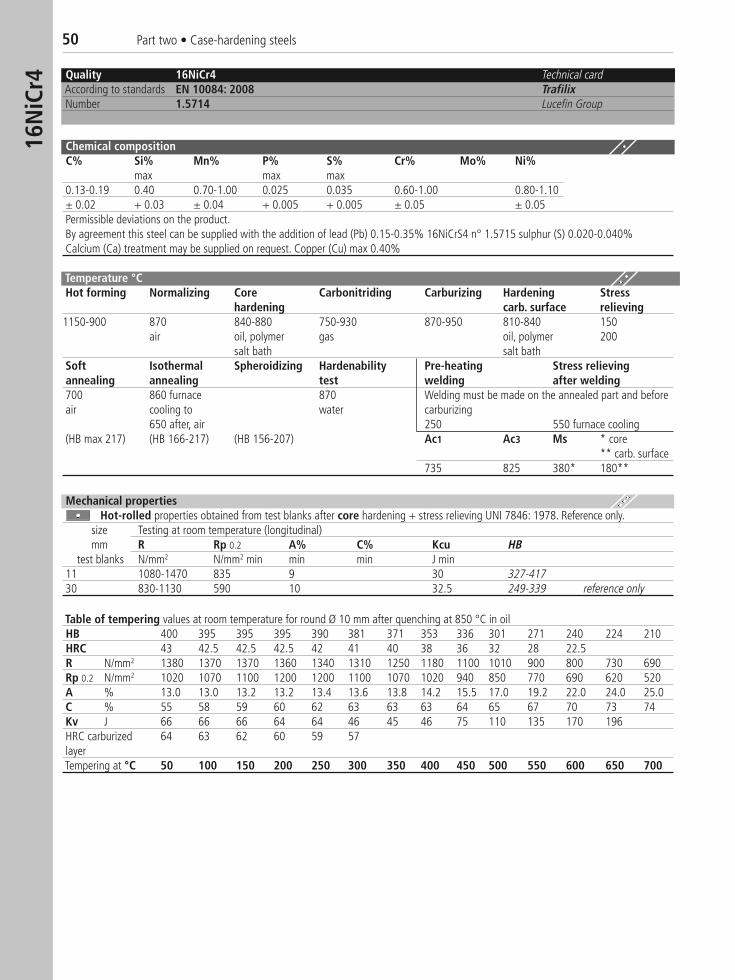
50 Part two • Case-hardening steels16
NiC
r4 Quality 16NiCr4 Technical cardAccording to standards EN 10084: 2008 TrafilixNumber 1.5714 Lucefin Group
Chemical compositionC% Si% Mn% P% S% Cr% Mo% Ni%
max max max0.13-0.19 0.40 0.70-1.00 0.025 0.035 0.60-1.00 0.80-1.10± 0.02 + 0.03 ± 0.04 + 0.005 + 0.005 ± 0.05 ± 0.05Permissible deviations on the product.By agreement this steel can be supplied with the addition of lead (Pb) 0.15-0.35% 16NiCrS4 n° 1.5715 sulphur (S) 0.020-0.040%Calcium (Ca) treatment may be supplied on request. Copper (Cu) max 0.40%
Temperature °CHot forming Normalizing Core Carbonitriding Carburizing Hardening Stress
hardening carb. surface relieving1150-900 870 840-880 750-930 870-950 810-840 150
air oil, polymer gas oil, polymer 200salt bath salt bath
Soft Isothermal Spheroidizing Hardenability Pre-heating Stress relievingannealing annealing test welding after welding700 860 furnace 870 Welding must be made on the annealed part and beforeair cooling to water carburizing
650 after, air 250 550 furnace cooling(HB max 217) (HB 166-217) (HB 156-207) Ac1 Ac3 Ms * core
** carb. surface735 825 380* 180**
Mechanical propertiesHot-rolled properties obtained from test blanks after core hardening + stress relieving UNI 7846: 1978. Reference only.
size Testing at room temperature (longitudinal) mm R Rp 0.2 A% C% Kcu HB
test blanks N/mm2 N/mm2 min min min J min11 1080-1470 835 9 30 327-41730 830-1130 590 10 32.5 249-339 reference only
Table of tempering values at room temperature for round Ø 10 mm after quenching at 850 °C in oilHB 400 395 395 395 390 381 371 353 336 301 271 240 224 210HRC 43 42.5 42.5 42.5 42 41 40 38 36 32 28 22.5R N/mm2 1380 1370 1370 1360 1340 1310 1250 1180 1100 1010 900 800 730 690Rp 0.2 N/mm2 1020 1070 1100 1200 1200 1100 1070 1020 940 850 770 690 620 520A % 13.0 13.0 13.2 13.2 13.4 13.6 13.8 14.2 15.5 17.0 19.2 22.0 24.0 25.0C % 55 58 59 60 62 63 63 63 64 65 67 70 73 74Kv J 66 66 66 64 64 46 45 46 75 110 135 170 196HRC carburized 64 63 62 60 59 57layerTempering at °C 50 100 150 200 250 300 350 400 450 500 550 600 650 700
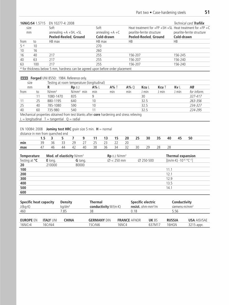
Part two • Case-hardening steels 51
16NiCrS4 1.5715 EN 10277-4: 2008 Technical card Trafilixsize Soft Soft Heat treatment for +FP +SH +SL Heat treatment for +FP +Cmm annealing +A +SH, +SL annealing +A +C pearlite-ferrite structure pearlite-ferrite structure
Peeled-Reeled, Ground Cold-drawn Peeled-Reeled, Ground Cold-drawnfrom to HB max HB max HB HB 5 a) 10 27010 16 26016 40 217 255 156-207 156-24540 63 217 255 156-207 156-24063 100 217 255 156-207 156-240a) for thickness below 5 mm, hardness can be agreed upon before order placement
Forged UNI 8550: 1984. Reference only.size Testing at room temperature (longitudinal)mm R Rp 0.2 A% L A% T A% Q Kcu L Kcu T Kv L HB
from to N/mm2 N/mm2 min min min min J min J min J min for inform.11 1080-1470 835 9 30 327-417
11 25 880-1195 640 10 32.5 263-35625 40 785-1080 590 10 32.5 234-32740 60 735-980 540 11 32.5 224-295Mechanical properties obtained from test blanks after core hardening and stress relievingL = longitudinal T = tangential Q = radial
Specific heat capacity Density Thermal Specific electric ConductivityJ/(kg·K) kg/dm3 conductivity W/(m·K) resist. ohm·mm2/m siemens·m/mm2
460 7.85 38 0.18 5.56
Temperature Mod. of elasticity N/mm2 Rp 0.2 N/mm2 Thermal expansionTesting at °C E long. G tang. ∅ < 250 mm ∅ 250-500 [(m/m·K) ·10–6 °C–1]20 210000 80000100 11.1200 12.1300 12.9400 13.5500 14.1600
EUROPE EN ITALY UNI CHINA GERMANY DIN FRANCE AFNOR UK BS RUSSIA USA AISI/SAE 16NiCr4 16CrNi4 15CrNi6 16NC4 637M17 16HGN 3215 appr.
EN 10084: 2008 Jominy test HRC grain size 5 min. H = normaldistance in mm from quenched end
1.5 3 5 7 9 11 13 15 20 25 30 35 40 45 50min 39 36 33 29 27 25 23 22 20max 47 46 44 42 40 38 36 34 32 30 29 28 28
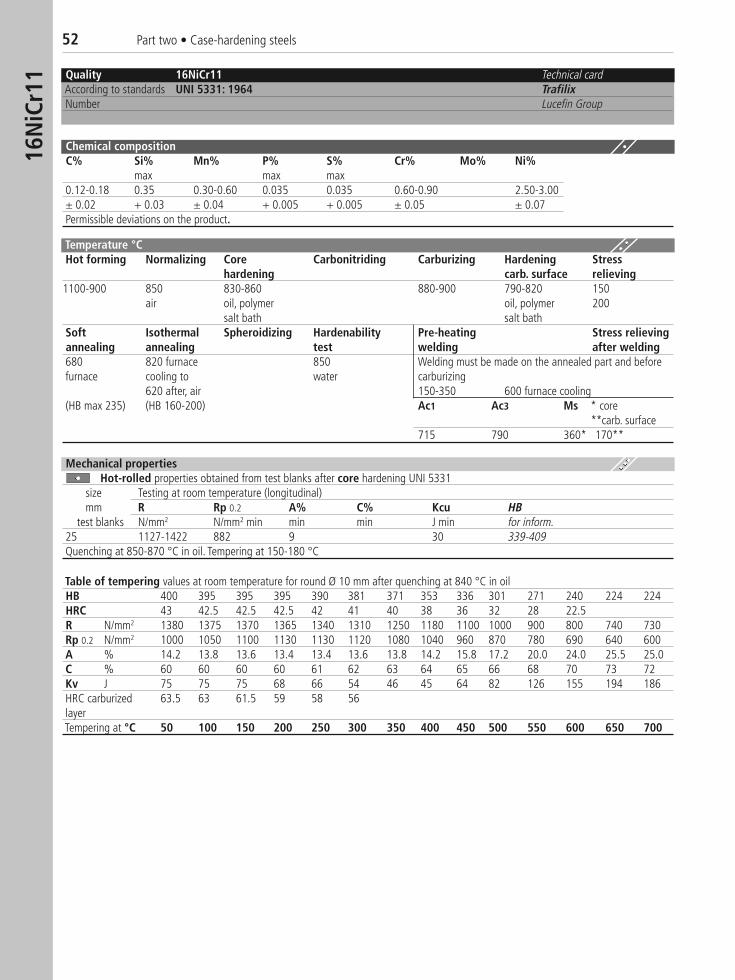
52 Part two • Case-hardening steels16
NiC
r11 Quality 16NiCr11 Technical card
According to standards UNI 5331: 1964 TrafilixNumber Lucefin Group
Chemical compositionC% Si% Mn% P% S% Cr% Mo% Ni%
max max max0.12-0.18 0.35 0.30-0.60 0.035 0.035 0.60-0.90 2.50-3.00± 0.02 + 0.03 ± 0.04 + 0.005 + 0.005 ± 0.05 ± 0.07Permissible deviations on the product.
Mechanical propertiesHot-rolled properties obtained from test blanks after core hardening UNI 5331
size Testing at room temperature (longitudinal)mm R Rp 0.2 A% C% Kcu HB
test blanks N/mm2 N/mm2 min min min J min for inform.25 1127-1422 882 9 30 339-409Quenching at 850-870 °C in oil. Tempering at 150-180 °C
Table of tempering values at room temperature for round Ø 10 mm after quenching at 840 °C in oilHB 400 395 395 395 390 381 371 353 336 301 271 240 224 224HRC 43 42.5 42.5 42.5 42 41 40 38 36 32 28 22.5R N/mm2 1380 1375 1370 1365 1340 1310 1250 1180 1100 1000 900 800 740 730Rp 0.2 N/mm2 1000 1050 1100 1130 1130 1120 1080 1040 960 870 780 690 640 600A % 14.2 13.8 13.6 13.4 13.4 13.6 13.8 14.2 15.8 17.2 20.0 24.0 25.5 25.0C % 60 60 60 60 61 62 63 64 65 66 68 70 73 72Kv J 75 75 75 68 66 54 46 45 64 82 126 155 194 186HRC carburized 63.5 63 61.5 59 58 56layerTempering at °C 50 100 150 200 250 300 350 400 450 500 550 600 650 700
Temperature °CHot forming Normalizing Core Carbonitriding Carburizing Hardening Stress
hardening carb. surface relieving1100-900 850 830-860 880-900 790-820 150
air oil, polymer oil, polymer 200salt bath salt bath
Soft Isothermal Spheroidizing Hardenability Pre-heating Stress relievingannealing annealing test welding after welding680 820 furnace 850 Welding must be made on the annealed part and beforefurnace cooling to water carburizing
620 after, air 150-350 600 furnace cooling(HB max 235) (HB 160-200) Ac1 Ac3 Ms * core
**carb. surface715 790 360* 170**
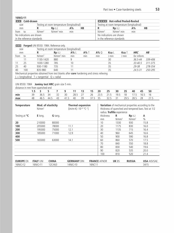
Part two • Case-hardening steels 53
16NiCr11Cold-drawn Hot-rolled Peeled-Reeled�
size Testing at room temperature (longitudinal) Testing at room temperature (longitudinal)mm R Rp 0.2 A% HB R Rp 0.2 A% HB
from to N/mm2 N/mm2 min min N/mm2 N/mm2 min minNo indications are shown No indications are shown in the reference standards in the reference standards
Forged UNI 8550: 1984. Reference only.size Testing at room temperature (longitudinal)mm R Rp 0.2 A% L A% T A% Q Kcu L Kcu T HRC HB
from to N/mm2 N/mm2 min min min min J min J min for inform.11 1130-1420 880 9 30 36.5-44 339-406
11 25 1030-1280 785 10 35 33-40.5 311-37525 40 930-1180 735 11 35 29-38 278-35440 100 835-980 640 11 35 24.5-31 250-295Mechanical properties obtained from test blanks after core hardening and stress relievingL = longitudinal T = tangential Q = radial
UNI 8550: 1984 Jominy test HRC grain size 5 min.distance in mm from quenched end
1.5 3 5 7 9 11 13 15 20 25 30 35 40 45 50min 39 36.5 34 32 30 28.5 27 26 23.5 21.5 19.5 18 17.5 16.5 16max 48 46.5 44.5 43 41.5 40 39 37.5 35 32.5 31 29.5 28.5 28 27.5
Temperature Mod. of elasticity Thermal expansion Variation of mechanical properties according to the N/mm2 [(m/m·K) ·10–6 °C–1] thickness of quenched and tempered bars. Test at 1/2
radius. Trafilix experience Testing at °C E long. G tang. thickness R Rp 0.2 A
mm N/mm2 N/mm2 %20 210000 80000 10 1330 930 15.8100 205000 78000 11.1 20 1175 830 16.0200 195000 75000 12.1 30 1135 715 16.4300 185000 71000 12.9 40 960 645 16.6400 50 900 590 16.8500 165000 63000 14.1 60 860 570 17.5
70 840 550 18.880 830 540 19.690 820 535 20.0100 810 520 21.4
EUROPE EN ITALY UNI CHINA GERMANY DIN FRANCE AFNOR UK BS RUSSIA USA AISI/SAE 16NiCr12 16NiCr11 12CrNi3 14NiCr10 16NC11 3415
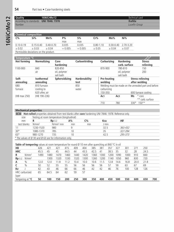
54 Part two • Case-hardening steels16
NiC
rMo1
2 Quality 16NiCrMo12 Technical cardAccording to standards UNI 7846: 1978 TrafilixNumber Lucefin Group
Chemical compositionC% Si% Mn% P% S% Cr% Mo% Ni%
max max0.13-0.19 0.15-0.40 0.40-0.70 0.035 0.035 0.80-1.10 0.30-0.40 2.70-3.20± 0.02 ± 0.03 ± 0.04 + 0.005 + 0.005 ± 0.05 ± 0.04 ± 0.07Permissible deviations on the product.
Temperature °CHot forming Normalizing Core Carbonitriding Carburizing Hardening Stress
hardening carb. surface relieving1100-900 840 820-850 870-900 780-810 150
air oil, polymer oil, polymer 200salt bath salt bath
Soft Isothermal Spheroidizing Hardenability Pre-heating Stress relievingannealing annealing test welding after welding680 810 furnace 850 Welding must be made on the annealed part and before furnace cooling to water carburizing
620 after, air 150-350 600 furnace cooling(HB max 250) (HB 190-236) Ac1 Ac3 Ms * core
** carb. surface710 780 330* 150**
Table of tempering values at room temperature for round Ø 10 mm after quenching at 840 °C in oilHB 426 421 421 415 409 404 385 381 357 327 301 271 250HRC 45.5 45 45 44.5 44 43.5 42.5 41 38.5 35 32 28 24.5R N/mm2 1490 1480 1470 1460 1440 1420 1360 1300 1200 1090 1000 910 840Rp 0.2 N/mm2 1300 1320 1330 1320 1300 1260 1200 1140 1050 960 830 720A % 12.0 12.0 11.8 11.2 10.4 10.0 10.6 11.5 12.8 14.6 16.8 20.0 21.8C % 50 52 55 55 56 56 56 56 57 59 63 67 69Kv J 42 43 46 66 66 46 42 42 46 76 100 128 126HRC carburized 65 64.5 64 62 59 57layerTempering at °C 50 100 150 200 250 300 350 400 450 500 550 600 650 700
Mechanical propertiesHot-rolled properties obtained from test blanks after core hardening UNI 7846: 1978. Reference only.
size Testing at room temperature (longitudinal)mm R Rp 0.2 A% C% Kcu HB
test blanks N/mm2 N/mm2 min min min J min11 1230-1520 980 9 32.5 363-43230* 1080-1370 785 10 35 327-39463* 980-1270 735 10 42.5 295-373* The values of Ø 30 and Ø 63 are for information only.

Part two • Case-hardening steels 55
16NiCrMo12 Technical card TrafilixCold-drawn Hot-rolled Peeled-Reeled
size Testing at room temperature (longitudinal) Testing at room temperature (longitudinal)mm R Rp 0.2 A% HB R Rp 0.2 A% HB
from to N/mm2 N/mm2 min min N/mm2 N/mm2 min minNo indications are shown No indications are shownin the reference standards in the reference standards
Forged UNI 8550: 1984. Reference only.size Testing at room temperature (longitudinal)mm R Rp 0.2 A% L A% T A% Q Kcu L Kcu T HRC HB
from to N/mm2 N/mm2 min min min min J min J min reference only11 1225-1520 980 8 32.5 39-46 361-432
11 25 1130-1500 835 9 35 36.5-45.5 339-42625 40 1030-1325 735 10 37 33-41.5 311-38440 100 930-1275 685 10 40 29-40 278-373100 150 835-1130 635 11 40 24.5-36.5 250-339Mechanical properties obtained from test blanks after core hardening and stress relievingL = longitudinal T = tangential Q = radial
UNI 7846: 1978 Jominy test HRC grain size 5 min.distance in mm from quenched end
1.5 3 5 7 9 11 13 15 20 25 30 35 40 45 50min 42 41.5 41 40.5 40 39 38.5 38 36.5 35.5 34 33 32 31 30max 48 48 48 47.5 47.5 47 47 46.5 45.5 44.5 44 43 42 41.5 41
Temperature Mod. of elasticity N/mm2 Rp 0.2 N/mm2 Thermal expansionTesting at °C E long. G tang. Ø < 250 mm Ø 250-500 [(m/m·K) ·10–6 °C–1]20 210000 80000
EUROPE EN ITALY UNI CHINA GERMANY DIN FRANCE AFNOR UK BS RUSSIA USA AISI/SAE 14NiCrMo13-4 16NiCrMo12 16NCD13 16HN3M 9314
NITRIDING STEELS
34CrAlNi7-10 • 41CrAlMo7-10
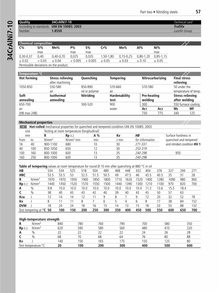
Part two • Nitriding steels 5734
CrA
lNi7
-10 Quality 34CrAlNi7-10 Technical card
According to standards UNI EN 10085: 2003 TrafilixNumber 1.8550 Lucefin Group
Chemical compositionC% Si% Mn% P% S% Cr% Mo% Al% Ni%
max max max max0,30-0,37 0,40 0,40-0,70 0,025 0,035 1,50-1,80 0,15-0,25 0,80-1,20 0,85-1,15± 0.02 + 0.03 ± 0.04 + 0.005 + 0.005 ± 0.05 ± 0.03 ± 0.10 ± 0.05Permissible deviations on the product.
Temperature °C Hot forming Stress relieving Quenching Tempering Nitrocarburizing Final stress
after machining relieving1050-850 550-580 850-890 570-660 570-580 50 under the
air oil or polymer air temperature of temp.Soft Isothermal Nitriding Hardenability Pre-heating Stress relievingannealing annealing test welding after welding650-700 500-520 900 300 550 furnace coolingair water Ac1 Ac3 Ms Mf(HB max 248) 730 775 340 125
Mechanical propertiesHot-rolled mechanical properties for quenched and tempered condition UNI EN 10085: 2003
size Testing at room temperature (longitudinal)mm R Rp 0.2 A % Kv HB Surface hardness in
from to N/mm2 N/mm2 min min J min for information quenched and tempered 16 40 900-1100 680 10 30 271-331 and nitrided condition HV 140 100 850-1050 650 12 30 253-319100 160 800-1000 600 13 35 240-298 950160 250 800-1000 600 13 35 240-298
Table of tempering values at room temperature for round Ø 10 mm after quenching at 880 °C in oil HB 534 534 525 518 504 489 468 448 432 404 376 327 294 271HRC 53.5 53.5 53 52.5 51.5 50.5 49 47.5 46 43.5 40.5 35 31 28R N/mm2 1970 1970 1950 1900 1850 1800 1710 1620 1520 1400 1280 1090 980 900Rp 0.2 N/mm2 1440 1450 1520 1570 1550 1500 1440 1390 1300 1210 1100 970 820 700A % 9.8 10.0 10.0 10.0 10.0 10.0 10.0 10.0 10.4 11.2 13.6 15.5 18.4C % 38 40 43 43 42 40 39 40 43 45 50 57 63Kcu J 12 14 14 12 11 9 8 7 9 12 20 32 52 78Kv J 8 11 11 8 7 6 5 4 6 8 17 38 84 152DVM J 18 24 24 18 16 15 14 13 15 18 33 55 88 132Test tempering at °C 50 100 150 200 250 300 350 400 450 500 550 600 650 700
High-temperature strengthR N/mm2 840 780 760 790 700 580 350Rp 0.2 N/mm2 620 590 580 560 480 410 220A % 22 22 22 22 24 26 28C % 68 70 68 64 76 80 88Kv J 140 150 165 175 150 125 80Test temperature °C 20 100 200 300 400 500 600
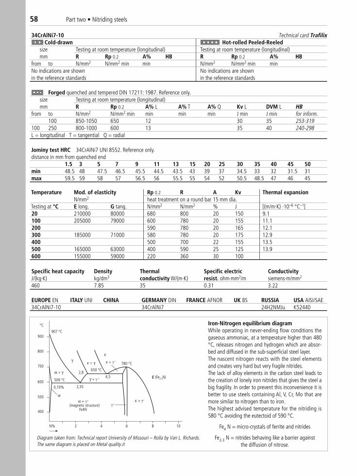
58 Part two • Nitriding steels
34CrAlNi7-10 Technical card TrafilixCold-drawn Hot-rolled Peeled-Reeled�
size Testing at room temperature (longitudinal) Testing at room temperature (longitudinal)mm R Rp 0.2 A% HB R Rp 0.2 A% HB
from to N/mm2 N/mm2 min min N/mm2 N/mm2 min minNo indications are shown No indications are shown in the reference standards in the reference standards
Forged quenched and tempered DIN 17211: 1987. Reference only.size Testing at room temperature (longitudinal)mm R Rp 0.2 A% L A% T A% Q Kv L DVM L HB
from to N/mm2 N/mm2 min min min min J min J min for inform.100 850-1050 650 12 30 35 253-319
100 250 800-1000 600 13 35 40 240-298L = longitudinal T = tangential Q = radial
Jominy test HRC 34CrAlNi7 UNI 8552. Reference only.distance in mm from quenched end
1.5 3 5 7 9 11 13 15 20 25 30 35 40 45 50min 48.5 48 47.5 46.5 45.5 44.5 43.5 43 39 37 34.5 33 32 31.5 31max 59.5 59 58 57 56.5 56 55.5 55 54 52 50.5 48.5 47 46 45
Temperature Mod. of elasticity Rp 0.2 R A Kv Thermal expansionN/mm2 heat treatment on a round bar 15 mm dia.
Testing at °C E long. G tang. N/mm2 N/mm2 % J [(m/m·K) ·10–6 °C–1]20 210000 80000 680 800 20 150 9.1100 205000 79000 600 780 20 155 11.1200 590 780 20 165 12.1300 185000 71000 580 780 20 175 12.9400 500 700 22 155 13.5500 165000 63000 400 590 25 125 13.9600 155000 59000 220 360 30 100
Specific heat capacity Density Thermal Specific electric ConductivityJ/(kg·K) kg/dm3 conductivity W/(m·K) resist. ohm·mm2/m siemens·m/mm2
460 7.85 35 0.31 3.22
EUROPE EN ITALY UNI CHINA GERMANY DIN FRANCE AFNOR UK BS RUSSIA USA AISI/SAE 34CrAlNi7-10 34CrAlNi7 24H2NMJu K52440
°C
900
800
700
600
500
400
907 °C
509 °C
650 °C
780 °C
0,10% 2,35
4,5,
,
,,,
N% 2 4 6 8 10
α + γ
α + (magnetic structure)
Fe4N
γ +
ε + ε + γ
ε +
γ
2,8
ε
α
ε (Fe2-3N)
Iron-Nitrogen equilibrium diagramWhile operating in never-ending flow conditions thegaseous ammoniac, at a temperature higher than 480°C, releases nitrogen and hydrogen which are absor-bed and diffused in the sub-superficial steel layer.The nascent nitrogen reacts with the steel elementsand creates very hard but very fragile nitrides.The lack of alloy elements in the carbon steel leads tothe creation of lonely iron nitrides that gives the steel abig fragility. In order to prevent this inconvenience it isbetter to use steels containing Al, V, Cr, Mo that aremore similar to nitrogen than to iron.The highest advised temperature for the nitriding is580 °C avoiding the eutectoid of 590 °C.
Fe4 N = micro-crystals of ferrite and nitrides
Fe2-3 N = nitrides behaving like a barrier against the diffusion of nitrose.
Diagram taken from: Technical report University of Missouri – Rolla by Van L. Richards. The same diagram is placed on Metal quality.it
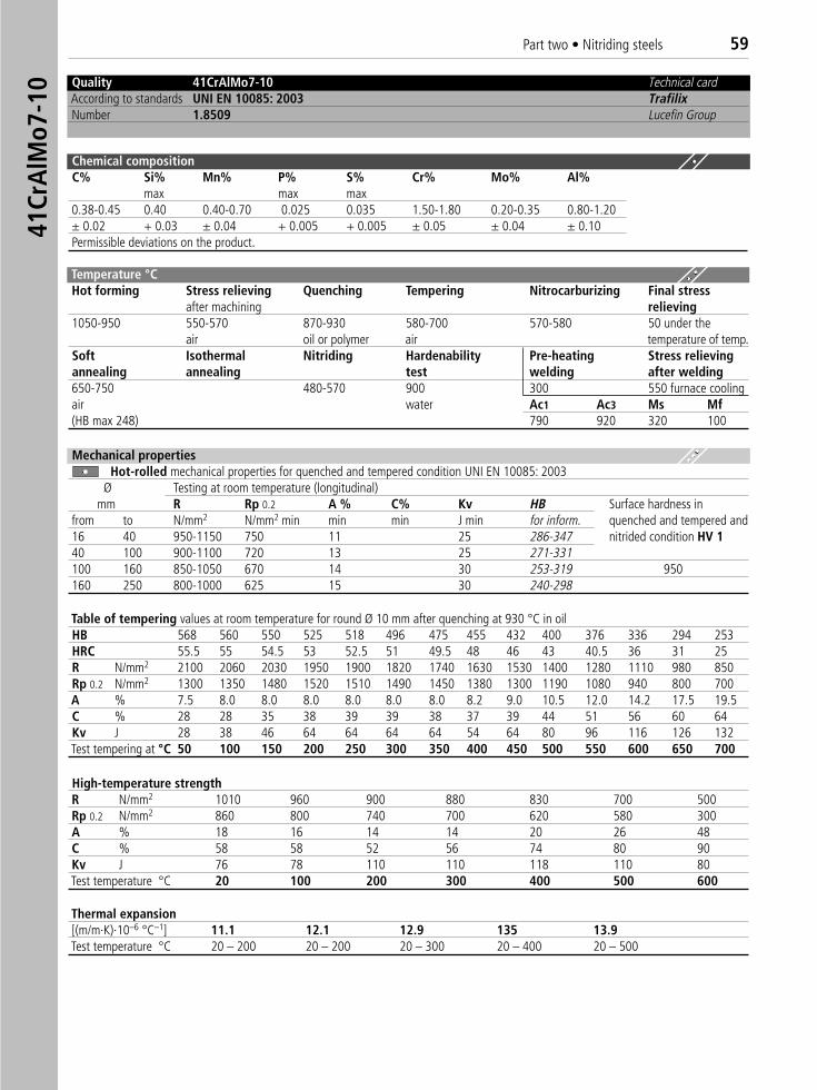
Part two • Nitriding steels 59
Quality 41CrAlMo7-10 Technical cardAccording to standards UNI EN 10085: 2003 TrafilixNumber 1.8509 Lucefin Group
Chemical compositionC% Si% Mn% P% S% Cr% Mo% Al%
max max max0.38-0.45 0.40 0.40-0.70 0.025 0.035 1.50-1.80 0.20-0.35 0.80-1.20± 0.02 + 0.03 ± 0.04 + 0.005 + 0.005 ± 0.05 ± 0.04 ± 0.10Permissible deviations on the product.
Temperature °C Hot forming Stress relieving Quenching Tempering Nitrocarburizing Final stress
after machining relieving1050-950 550-570 870-930 580-700 570-580 50 under the
air oil or polymer air temperature of temp.Soft Isothermal Nitriding Hardenability Pre-heating Stress relievingannealing annealing test welding after welding650-750 480-570 900 300 550 furnace coolingair water Ac1 Ac3 Ms Mf(HB max 248) 790 920 320 100
Mechanical propertiesHot-rolled mechanical properties for quenched and tempered condition UNI EN 10085: 2003
Ø Testing at room temperature (longitudinal)mm R Rp 0.2 A % C% Kv HB Surface hardness in
from to N/mm2 N/mm2 min min min J min for inform. quenched and tempered and 16 40 950-1150 750 11 25 286-347 nitrided condition HV 140 100 900-1100 720 13 25 271-331100 160 850-1050 670 14 30 253-319 950160 250 800-1000 625 15 30 240-298
Table of tempering values at room temperature for round Ø 10 mm after quenching at 930 °C in oilHB 568 560 550 525 518 496 475 455 432 400 376 336 294 253HRC 55.5 55 54.5 53 52.5 51 49.5 48 46 43 40.5 36 31 25R N/mm2 2100 2060 2030 1950 1900 1820 1740 1630 1530 1400 1280 1110 980 850Rp 0.2 N/mm2 1300 1350 1480 1520 1510 1490 1450 1380 1300 1190 1080 940 800 700A % 7.5 8.0 8.0 8.0 8.0 8.0 8.0 8.2 9.0 10.5 12.0 14.2 17.5 19.5C % 28 28 35 38 39 39 38 37 39 44 51 56 60 64Kv J 28 38 46 64 64 64 64 54 64 80 96 116 126 132Test tempering at °C 50 100 150 200 250 300 350 400 450 500 550 600 650 700
High-temperature strengthR N/mm2 1010 960 900 880 830 700 500Rp 0.2 N/mm2 860 800 740 700 620 580 300A % 18 16 14 14 20 26 48C % 58 58 52 56 74 80 90Kv J 76 78 110 110 118 110 80Test temperature °C 20 100 200 300 400 500 600
Thermal expansion[(m/m·K)·10–6 °C–1] 11.1 12.1 12.9 135 13.9Test temperature °C 20 – 200 20 – 200 20 – 300 20 – 400 20 – 500
41Cr
AlM
o7-1
0
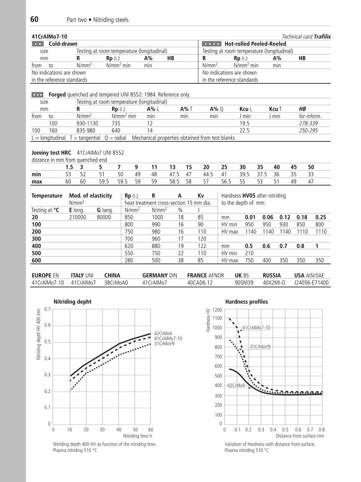
60 Part two • Nitriding steels
41CrAlMo7-10 Technical card TrafilixCold-drawn Hot-rolled Peeled-Reeled� �
size Testing at room temperature (longitudinal) Testing at room temperature (longitudinal)mm R Rp 0.2 A% HB R Rp 0.2 A% HB
from to N/mm2 N/mm2 min min N/mm2 N/mm2 min minNo indications are shown No indications are shownin the reference standards in the reference standards
Forged quenched and tempered UNI 8552: 1984. Reference only.size Testing at room temperature (longitudinal)mm R Rp 0.2 A% L A% T A% Q Kcu L Kcu T HB
from to N/mm2 N/mm2 min min min min J min J min for inform.100 930-1130 735 12 19.5 278-339
100 160 835-980 640 14 22.5 250-295L = longitudinal T = tangential Q = radial Mechanical properties obtained from test blanks
Jominy test HRC 41CrAlMo7 UNI 8552distance in mm from quenched end
1.5 3 5 7 9 11 13 15 20 25 30 35 40 45 50min 53 52 51 50 49 48 47.5 47 44.5 41 39.5 37.5 36 35 33max 60 60 59.5 59.5 59 59 58.5 58 57 56.5 55 53 51 49 47
Temperature Mod. of elasticity Rp 0.2 R A Kv Hardness HV05 after nitridingN/mm2 heat treatment cross-section 15 mm dia. to the depth of mm:
Testing at °C E long. G tang. N/mm2 N/mm2 % J20 210000 80000 850 1000 18 85 mm 0.01 0.06 0.12 0.18 0.25100 800 990 16 90 HV min 950 950 930 850 800200 750 980 16 110 HV max 1140 1140 1140 1110 1110300 700 960 17 120400 620 880 19 122 mm 0.5 0.6 0.7 0.8 1500 550 750 22 110 HV min 210600 280 500 38 85 HV max 750 400 350 350 350
EUROPE EN ITALY UNI CHINA GERMANY DIN FRANCE AFNOR UK BS RUSSIA USA AISI/SAE 41CrAlMo7-10 41CrAlMo7 38CrMoA0 41CrAlMo7 40CAD6.12 905M39 40X2MI-O J24056-E71400
Nitriding Depth Hardness profiles1200
1100
1000
900
800
700
600
500
400
300
200
100
00.10 0.2 0.3 0.4 0.5 0.6 0.7 0.8
0.7
0.6
0.5
0.4
0.3
0.2
0.1
00 10 20 30 40 50 60
Nitriding time h
42CrMo441CrAIMo7-1031CrMoV9
42CrMo4
41CrAIMo7-10
31CrMoV9
Nitriding depth 400 HV as function of the nitriding time.Plasma nitriding 510 °C
Distance from surface mm
Variation of Hardness with distance from surface.Plasma nitriding 510 °C
Nitr
idin
g de
pth
HV 4
00 m
m
Hard
ness
HV
Nitriding depht Hardness profiles
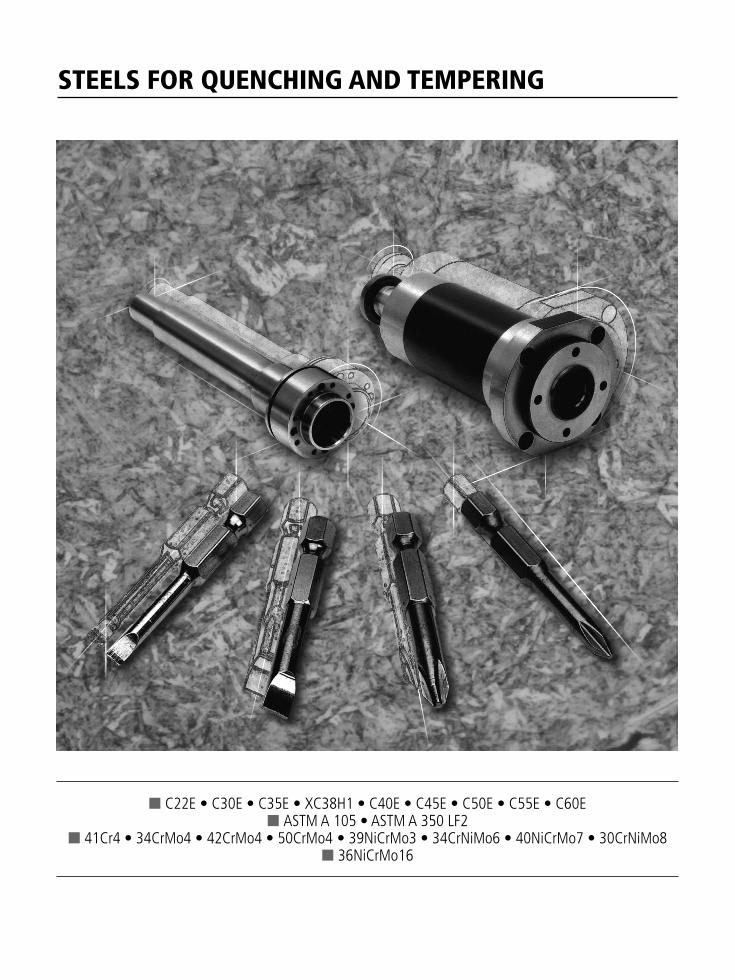
STEELS FOR QUENCHING AND TEMPERING
■ C22E • C30E • C35E • XC38H1 • C40E • C45E • C50E • C55E • C60E■ ASTM A 105 • ASTM A 350 LF2
■ 41Cr4 • 34CrMo4 • 42CrMo4 • 50CrMo4 • 39NiCrMo3 • 34CrNiMo6 • 40NiCrMo7 • 30CrNiMo8 ■ 36NiCrMo16
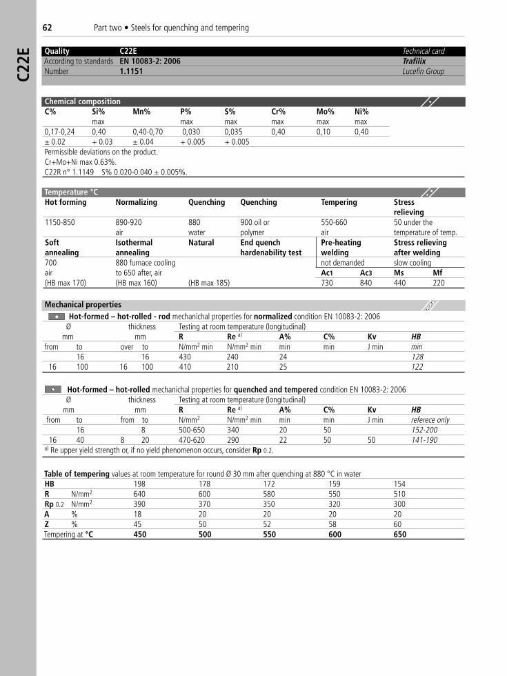
62 Part two • Steels for quenching and temperingC2
2E
Quality C22E Technical cardAccording to standards EN 10083-2: 2006 TrafilixNumber 1.1151 Lucefin Group
Temperature °C Hot forming Normalizing Quenching Quenching Tempering Stress
relieving1150-850 890-920 880 900 oil or 550-660 50 under the
air water polymer air temperature of temp.Soft Isothermal Natural End quench Pre-heating Stress relievingannealing annealing hardenability test welding after welding700 880 furnace cooling not demanded slow coolingair to 650 after, air Ac1 Ac3 Ms Mf(HB max 170) (HB max 160) (HB max 185) 730 840 440 220
Mechanical propertiesHot-formed – hot-rolled - rod mechanichal properties for normalized condition EN 10083-2: 2006
Ø thickness Testing at room temperature (longitudinal)mm mm R Re a) A% C% Kv HB
from to over to N/mm2 min N/mm2 min min min J min min16 16 430 240 24 128
16 100 16 100 410 210 25 122
Hot-formed – hot-rolled mechanichal properties for quenched and tempered condition EN 10083-2: 2006Ø thickness Testing at room temperature (longitudinal)
mm mm R Re a) A% C% Kv HBfrom to from to N/mm2 N/mm2 min min min J min referece only
16 8 500-650 340 20 50 152-20016 40 8 20 470-620 290 22 50 50 141-190
a) Re upper yield strength or, if no yield phenomenon occurs, consider Rp 0.2.
Table of tempering values at room temperature for round Ø 30 mm after quenching at 880 °C in waterHB 198 178 172 159 154R N/mm2 640 600 580 550 510Rp 0.2 N/mm2 390 370 350 320 300A % 18 20 20 20 20Z % 45 50 52 58 60Tempering at °C 450 500 550 600 650
Chemical compositionC% Si% Mn% P% S% Cr% Mo% Ni%
max max max max max max0,17-0,24 0,40 0,40-0,70 0,030 0,035 0,40 0,10 0,40± 0.02 + 0.03 ± 0.04 + 0.005 + 0.005Permissible deviations on the product.Cr+Mo+Ni max 0.63%.C22R n° 1.1149 S% 0.020-0.040 ± 0.005%.
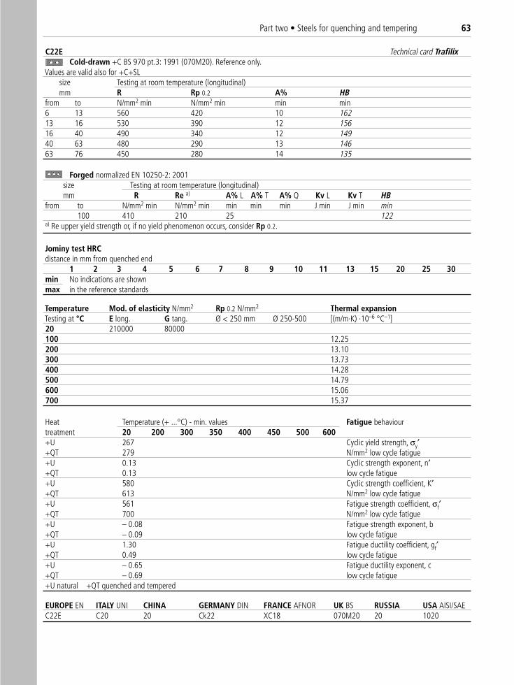
Part two • Steels for quenching and tempering 63
C22E Technical card TrafilixCold-drawn +C BS 970 pt.3: 1991 (070M20). Reference only.
Values are valid also for +C+SL size Testing at room temperature (longitudinal)mm R Rp 0.2 A% HB
from to N/mm2 min N/mm2 min min min6 13 560 420 10 16213 16 530 390 12 15616 40 490 340 12 14940 63 480 290 13 14663 76 450 280 14 135
Forged normalized EN 10250-2: 2001size Testing at room temperature (longitudinal)mm R Re a) A% L A% T A% Q Kv L Kv T HB
from to N/mm2 min N/mm2 min min min min J min J min min100 410 210 25 122
a) Re upper yield strength or, if no yield phenomenon occurs, consider Rp 0.2.
Jominy test HRC distance in mm from quenched end
1 2 3 4 5 6 7 8 9 10 11 13 15 20 25 30min No indications are shown max in the reference standards
Temperature Mod. of elasticity N/mm2 Rp 0.2 N/mm2 Thermal expansionTesting at °C E long. G tang. Ø < 250 mm Ø 250-500 [(m/m·K) ·10–6 °C–1]20 210000 80000100 12.25200 13.10300 13.73400 14.28500 14.79600 15.06700 15.37
Heat Temperature (+ ...°C) - min. values Fatigue behaviourtreatment 20 200 300 350 400 450 500 600+U 267 Cyclic yield strength, σy′+QT 279 N/mm2 low cycle fatigue+U 0.13 Cyclic strength exponent, n′+QT 0.13 low cycle fatigue+U 580 Cyclic strength coefficient, K′+QT 613 N/mm2 low cycle fatigue+U 561 Fatigue strength coefficient, σf′+QT 700 N/mm2 low cycle fatigue+U – 0.08 Fatigue strength exponent, b+QT – 0.09 low cycle fatigue+U 1.30 Fatigue ductility coefficient, gf′+QT 0.49 low cycle fatigue+U – 0.65 Fatigue ductility exponent, c+QT – 0.69 low cycle fatigue+U natural +QT quenched and tempered
EUROPE EN ITALY UNI CHINA GERMANY DIN FRANCE AFNOR UK BS RUSSIA USA AISI/SAE C22E C20 20 Ck22 XC18 070M20 20 1020
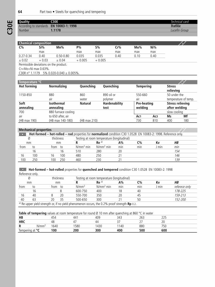
64 Part two • Steels for quenching and temperingC3
0E
Quality C30E Technical cardAccording to standards EN 10083-1: 1998 TrafilixNumber 1.1178 Lucefin Group
Chemical compositionC% Si% Mn% P% S% Cr% Mo% Ni%
max max max max max max0.27-0.34 0.40 0.50-0.80 0.035 0.035 0.40 0.10 0.40± 0.02 + 0.03 ± 0.04 + 0.005 + 0.005Permissible deviations on the product.Cr+Mo+Ni max 0.63%.C30R n° 1.1179 S% 0.020-0.040 ± 0.005%.
Temperature °C Hot forming Normalizing Quenching Quenching Tempering Stress
relieving1150-850 880 860 890 oil or 550-660 50 under the
air water polymer air temperature of temp.Soft Isothermal Natural Hardenability Pre-heating Stress relievingannealing annealing test welding after welding700 880 furnace cooling slow coolingair to 650 after, air Ac1 Ac3 Ms Mf(HB max 190) (HB max 140-180) (HB max 210) 730 810 400 180
Table of tempering values at room temperature for round Ø 10 mm after quenching at 860 °C in waterHB 454 441 409 343 263 225HRC 48 47 44 37 27 20R N/mm2 1640 1580 1430 1140 880 750Tempering at °C 100 200 300 400 500 600
Mechanical propertiesHot-formed – hot-rolled – rod properties for normalized condition C30 1.0528 EN 10083-2: 1998. Reference only.
Ø thickness Testing at room temperature (longitudinal)mm mm R Re a) A% C% Kv HB
from to from to N/mm2 min N/mm2 min min min J min min16 16 510 280 20 154
16 100 16 100 480 250 21 146100 250 100 250 460 230 21 139
Hot-formed – hot-rolled properties for quenched and tempered condition C30 1.0528 EN 10083-2: 1998Reference only.
Ø thickness Testing at room temperature (longitudinal)mm mm R Re a) A% C% Kv HB
from to from to N/mm2 N/mm2 min min min J min referece only16 8 600-750 400 18 40 178-225
16 40 8 20 550-700 350 20 45 159-21340 63 20 35 500-650 300 21 50 152-200
a) Re upper yield strength or, if no yield phenomenon occurs, the 0.2% proof strength Rp 0.2.
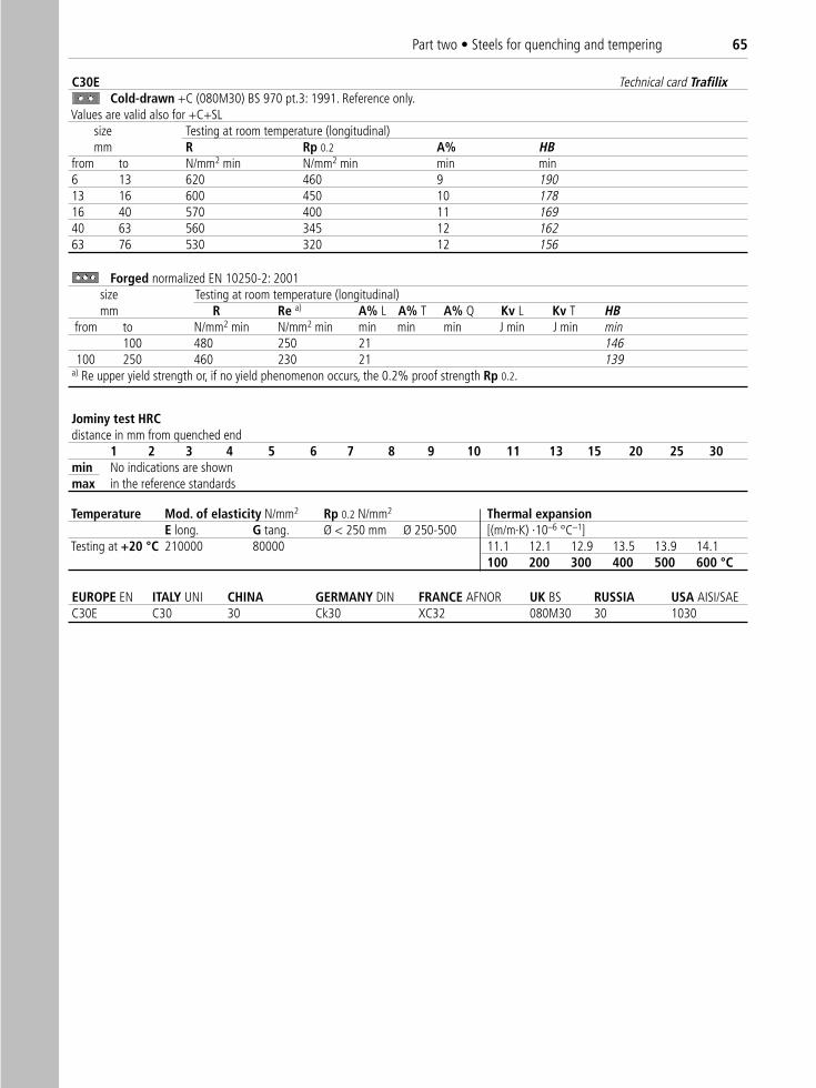
Part two • Steels for quenching and tempering 65
C30E Technical card TrafilixCold-drawn +C (080M30) BS 970 pt.3: 1991. Reference only.
Values are valid also for +C+SLsize Testing at room temperature (longitudinal)mm R Rp 0.2 A% HB
from to N/mm2 min N/mm2 min min min6 13 620 460 9 19013 16 600 450 10 17816 40 570 400 11 16940 63 560 345 12 16263 76 530 320 12 156
Jominy test HRC distance in mm from quenched end
1 2 3 4 5 6 7 8 9 10 11 13 15 20 25 30min No indications are shown max in the reference standards
Temperature Mod. of elasticity N/mm2 Rp 0.2 N/mm2 Thermal expansionE long. G tang. Ø < 250 mm Ø 250-500 [(m/m·K) ·10–6 °C–1]
Testing at +20 °C 210000 80000 11.1 12.1 12.9 13.5 13.9 14.1100 200 300 400 500 600 °C
EUROPE EN ITALY UNI CHINA GERMANY DIN FRANCE AFNOR UK BS RUSSIA USA AISI/SAE C30E C30 30 Ck30 XC32 080M30 30 1030
Forged normalized EN 10250-2: 2001size Testing at room temperature (longitudinal)mm R Re a) A% L A% T A% Q Kv L Kv T HB
from to N/mm2 min N/mm2 min min min min J min J min min100 480 250 21 146
100 250 460 230 21 139a) Re upper yield strength or, if no yield phenomenon occurs, the 0.2% proof strength Rp 0.2.
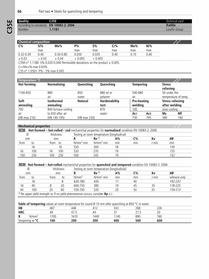
66 Part two • Steels for quenching and temperingC3
5E
Quality C35E Technical cardAccording to standards EN 10083-2: 2006 TrafilixNumber 1.1181 Lucefin Group
Chemical compositionC% Si% Mn% P% S% Cr% Mo% Ni%
max max max max max max0.32-0.39 0.40 0.50-0.80 0.030 0.035 0.40 0.10 0.40± 0.02 + 0.03 ± 0.04 + 0.005 + 0.005C35R n° 1.1180 S% 0.020-0.040 Permissible deviations on the product ± 0.005.Cr+Mo+Ni max 0.63%C35 n° 1.0501 P% - S% max 0.045
Temperature °C Hot forming Normalizing Quenching Quenching Tempering Stress
relieving1100-850 880 850 880 oil or 540-680 50 under the
air water polymer air temperature of temp.Soft Isothermal Natural Hardenability Pre-heating Stress relievingannealing annealing test welding after welding700 840 furnace cooling 870 100 slow coolingair to 650 after, air water Ac1 Ac3 Ms Mf(HB max 210) (HB 140-195) (HB max 220) 730 795 380 160
Table of tempering values at room temperature for round Ø 10 mm after quenching at 850 °C in waterHB 467 448 412 343 268 226HRC 49 47.5 44 37 27.5 20R N/mm2 1700 1610 1440 1140 890 760Tempering at °C 100 200 300 400 500 600
Mechanical propertiesHot-formed – hot-rolled - rod mechanichal properties for normalized condition EN 10083-2: 2006
Ø thickness Testing at room temperature (longitudinal)mm mm R Re a) A% C% Kv HB
from to from to N/mm2 min N/mm2 min min min J min min16 16 550 300 18 159
16 100 16 100 520 270 19 155100 250 100 250 500 245 19 152
Hot-formed – hot-rolled mechanichal properties for quenched and tempered condition EN 10083-2: 2006Ø thickness Testing at room temperature (longitudinal)
mm mm R Re a) A% C% Kv HBfrom to from to N/mm2 N/mm2 min min min J min referece only
16 8 630-780 430 17 40 192-23216 40 8 20 600-750 380 19 45 35 178-22540 100 20 60 550-700 320 20 50 35 159-213
a) Re upper yield strength or, if no yield phenomenon occurs, consider Rp 0.2.
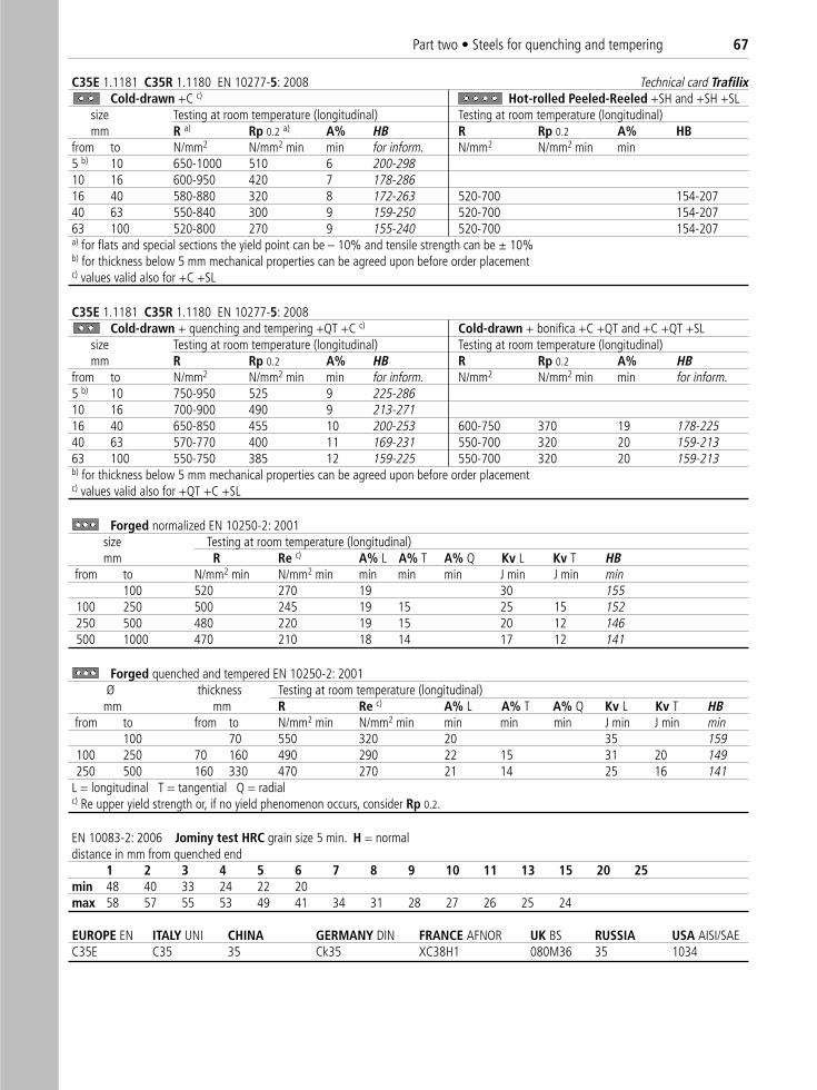
Part two • Steels for quenching and tempering 67
C35E 1.1181 C35R 1.1180 EN 10277-5: 2008 Technical card TrafilixCold-drawn +C c) Hot-rolled Peeled-Reeled +SH and +SH +SL
size Testing at room temperature (longitudinal) Testing at room temperature (longitudinal)mm R a) Rp 0.2 a) A% HB R Rp 0.2 A% HB
from to N/mm2 N/mm2 min min for inform. N/mm2 N/mm2 min min5 b) 10 650-1000 510 6 200-29810 16 600-950 420 7 178-28616 40 580-880 320 8 172-263 520-700 154-20740 63 550-840 300 9 159-250 520-700 154-20763 100 520-800 270 9 155-240 520-700 154-207a) for flats and special sections the yield point can be – 10% and tensile strength can be ± 10%b) for thickness below 5 mm mechanical properties can be agreed upon before order placementc) values valid also for +C +SL
C35E 1.1181 C35R 1.1180 EN 10277-5: 2008Cold-drawn + quenching and tempering +QT +C c) Cold-drawn + bonifica +C +QT and +C +QT +SL
size Testing at room temperature (longitudinal) Testing at room temperature (longitudinal)mm R Rp 0.2 A% HB R Rp 0.2 A% HB
from to N/mm2 N/mm2 min min for inform. N/mm2 N/mm2 min min for inform.5 b) 10 750-950 525 9 225-28610 16 700-900 490 9 213-27116 40 650-850 455 10 200-253 600-750 370 19 178-22540 63 570-770 400 11 169-231 550-700 320 20 159-21363 100 550-750 385 12 159-225 550-700 320 20 159-213b) for thickness below 5 mm mechanical properties can be agreed upon before order placementc) values valid also for +QT +C +SL
Forged quenched and tempered EN 10250-2: 2001Ø thickness Testing at room temperature (longitudinal)mm mm R Re c) A% L A% T A% Q Kv L Kv T HB
from to from to N/mm2 min N/mm2 min min min min J min J min min100 70 550 320 20 35 159
100 250 70 160 490 290 22 15 31 20 149250 500 160 330 470 270 21 14 25 16 141
L = longitudinal T = tangential Q = radialc) Re upper yield strength or, if no yield phenomenon occurs, consider Rp 0.2.
EN 10083-2: 2006 Jominy test HRC grain size 5 min. H = normaldistance in mm from quenched end
1 2 3 4 5 6 7 8 9 10 11 13 15 20 25min 48 40 33 24 22 20max 58 57 55 53 49 41 34 31 28 27 26 25 24
EUROPE EN ITALY UNI CHINA GERMANY DIN FRANCE AFNOR UK BS RUSSIA USA AISI/SAE C35E C35 35 Ck35 XC38H1 080M36 35 1034
Forged normalized EN 10250-2: 2001size Testing at room temperature (longitudinal)mm R Re c) A% L A% T A% Q Kv L Kv T HB
from to N/mm2 min N/mm2 min min min min J min J min min100 520 270 19 30 155
100 250 500 245 19 15 25 15 152250 500 480 220 19 15 20 12 146500 1000 470 210 18 14 17 12 141
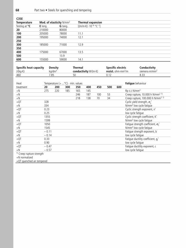
68 Part two • Steels for quenching and tempering
C35ETemperature Mod. of elasticity N/mm2 Thermal expansionTesting at °C E long. G tang. [(m/m·K) ·10–6 °C–1]20 210000 80000100 205000 78000 11.1200 195000 74000 12.1250300 185000 71000 12.9350400 175000 67000 13.5500 13.9600 155000 59000 14.1
Specific heat capacity Density Thermal Specific electric ConductivityJ/(kg·K) kg/dm3 conductivity W/(m·K) resist. ohm·mm2/m siemens·m/mm2
460 7.85 50 0.12 8.33
Heat Temperature (+ ...°C) - min. values Fatigue behaviour treatment 20 200 300 350 400 450 500 600+N 275 220 185 165 145 Rp 0.2 N/mm2
+N 246 187 100 53 Creep rupture, 10.000 h N/mm2 1)
+N 218 138 70 34 Creep rupture, 100.000 h N/mm2 1)
+QT 328 Cyclic yield strength, σy’+N 334 N/mm2 low cycle fatigue+QT 0.23 Cyclic strength exponent, n’+N 0.25 low cycle fatigue+QT 1355 Cyclic strength coefficient, K‘+N 1599 N/mm2 low cycle fatigue+QT 1050 Fatigue strength coefficient, σf‘+N 1545 N/mm2 low cycle fatigue+QT – 0.11 Fatigue strength exponent, b+N – 0.14 low cycle fatigue+QT 0.33 Fatigue ductility coefficient, gf‘+N 0.90 low cycle fatigue+QT – 0.47 Fatigue ductility exponent, c +N – 0.57 low cycle fatigue1) Creep rupture strength+N normalized+QT quenched an tempered
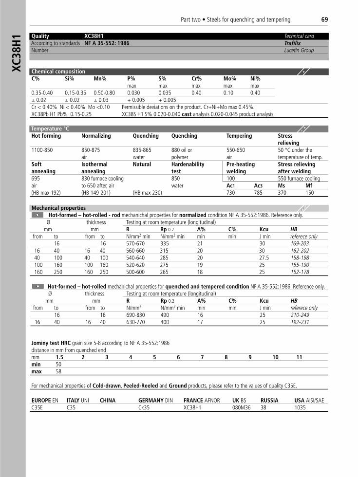
Part two • Steels for quenching and tempering 69
Chemical compositionC% Si% Mn% P% S% Cr% Mo% Ni%
max max max max max0.35-0.40 0.15-0.35 0.50-0.80 0.030 0.035 0.40 0.10 0.40± 0.02 ± 0.02 ± 0.03 + 0.005 + 0.005Cr < 0.40% Ni < 0.40% Mo <0.10 Permissible deviations on the product. Cr+Ni+Mo max 0.45%.XC38Pb H1 Pb% 0.15-0.25 XC38S H1 S% 0.020-0.040 cast analysis 0.020-0.045 product analysis
Temperature °C Hot forming Normalizing Quenching Quenching Tempering Stress
relieving1100-850 850-875 835-865 880 oil or 550-650 50 °C under the
air water polymer air temperature of temp.Soft Isothermal Natural Hardenability Pre-heating Stress relievingannealing annealing test welding after welding695 830 furnace cooling 850 100 550 furnace coolingair to 650 after, air water Ac1 Ac3 Ms Mf(HB max 192) (HB 149-201) (HB max 230) 730 785 370 150
Jominy test HRC grain size 5-8 according to NF A 35-552:1986distance in mm from quenched endmm 1.5 2 3 4 5 6 7 8 9 10 11min 50max 58
For mechanical properties of Cold-drawn, Peeled-Reeled and Ground products, please refer to the values of quality C35E.
EUROPE EN ITALY UNI CHINA GERMANY DIN FRANCE AFNOR UK BS RUSSIA USA AISI/SAE C35E C35 Ck35 XC38H1 080M36 38 1035
Mechanical propertiesHot-formed – hot-rolled - rod mechanichal properties for normalized condition NF A 35-552:1986. Reference only.
Ø thickness Testing at room temperature (longitudinal) mm mm R Rp 0.2 A% C% Kcu HB
from to from to N/mm2 min N/mm2 min min min J min referece only16 16 570-670 335 21 30 169-203
16 40 16 40 560-660 315 20 30 162-20240 100 40 100 540-640 285 20 27.5 158-198100 160 100 160 520-620 275 19 25 155-190160 250 160 250 500-600 265 18 25 152-178
Hot-formed – hot-rolled mechanichal properties for quenched and tempered condition NF A 35-552:1986. Reference only.Ø thickness Testing at room temperature (longitudinal)
mm mm R Rp 0.2 A% C% Kcu HBfrom to from to N/mm2 N/mm2 min min min J min referece only
16 16 690-830 490 16 25 210-24916 40 16 40 630-770 400 17 25 192-231
Quality XC38H1 Technical cardAccording to standards NF A 35-552: 1986 TrafilixNumber Lucefin Group
XC38
H1
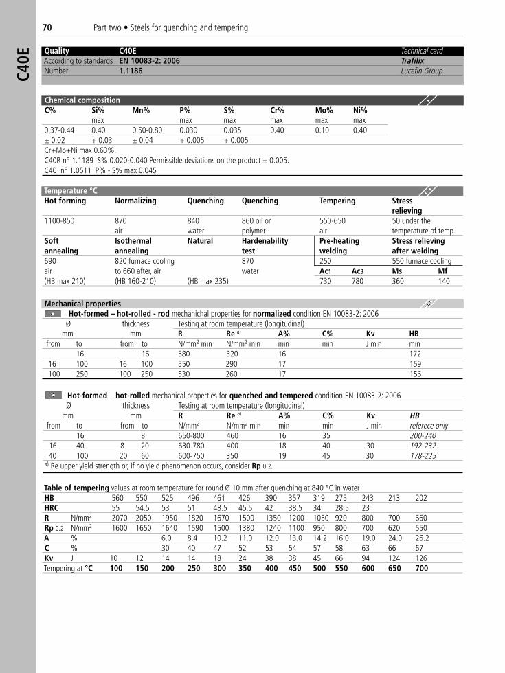
70 Part two • Steels for quenching and temperingC4
0E
Quality C40E Technical cardAccording to standards EN 10083-2: 2006 TrafilixNumber 1.1186 Lucefin Group
Chemical compositionC% Si% Mn% P% S% Cr% Mo% Ni%
max max max max max max0.37-0.44 0.40 0.50-0.80 0.030 0.035 0.40 0.10 0.40± 0.02 + 0.03 ± 0.04 + 0.005 + 0.005Cr+Mo+Ni max 0.63%.C40R n° 1.1189 S% 0.020-0.040 Permissible deviations on the product ± 0.005.C40 n° 1.0511 P% - S% max 0.045
Table of tempering values at room temperature for round Ø 10 mm after quenching at 840 °C in waterHB 560 550 525 496 461 426 390 357 319 275 243 213 202HRC 55 54.5 53 51 48.5 45.5 42 38.5 34 28.5 23R N/mm2 2070 2050 1950 1820 1670 1500 1350 1200 1050 920 800 700 660Rp 0.2 N/mm2 1600 1650 1640 1590 1500 1380 1240 1100 950 800 700 620 550A % 6.0 8.4 10.2 11.0 12.0 13.0 14.2 16.0 19.0 24.0 26.2C % 30 40 47 52 53 54 57 58 63 66 67Kv J 10 12 14 14 18 24 38 38 45 66 94 124 126Tempering at °C 100 150 200 250 300 350 400 450 500 550 600 650 700
Mechanical propertiesHot-formed – hot-rolled - rod mechanichal properties for normalized condition EN 10083-2: 2006
Ø thickness Testing at room temperature (longitudinal) mm mm R Re a) A% C% Kv HB
from to from to N/mm2 min N/mm2 min min min J min min16 16 580 320 16 172
16 100 16 100 550 290 17 159100 250 100 250 530 260 17 156
Hot-formed – hot-rolled mechanical properties for quenched and tempered condition EN 10083-2: 2006Ø thickness Testing at room temperature (longitudinal)
mm mm R Re a) A% C% Kv HBfrom to from to N/mm2 N/mm2 min min min J min referece only
16 8 650-800 460 16 35 200-24016 40 8 20 630-780 400 18 40 30 192-23240 100 20 60 600-750 350 19 45 30 178-225
a) Re upper yield strength or, if no yield phenomenon occurs, consider Rp 0.2.
Temperature °C Hot forming Normalizing Quenching Quenching Tempering Stress
relieving1100-850 870 840 860 oil or 550-650 50 under the
air water polymer air temperature of temp.Soft Isothermal Natural Hardenability Pre-heating Stress relievingannealing annealing test welding after welding690 820 furnace cooling 870 250 550 furnace coolingair to 660 after, air water Ac1 Ac3 Ms Mf(HB max 210) (HB 160-210) (HB max 235) 730 780 360 140
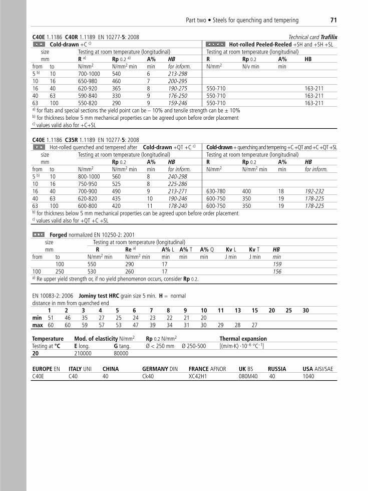
Part two • Steels for quenching and tempering 71
C40E 1.1186 C40R 1.1189 EN 10277-5: 2008 Technical card TrafilixCold-drawn +C c) Hot-rolled Peeled-Reeled +SH and +SH +SL
size Testing at room temperature (longitudinal) Testing at room temperature (longitudinal)mm R a) Rp 0.2 a) A% HB R Rp 0.2 A% HB
from to N/mm2 N/mm2 min min for inform. N/mm2 N/v min min5 b) 10 700-1000 540 6 213-29810 16 650-980 460 7 200-29516 40 620-920 365 8 190-275 550-710 163-21140 63 590-840 330 9 176-250 550-710 163-21163 100 550-820 290 9 159-246 550-710 163-211a) for flats and special sections the yield point can be – 10% and tensile strength can be ± 10%b) for thickness below 5 mm mechanical properties can be agreed upon before order placementc) values valid also for +C+SL
C40E 1.1186 C35R 1.1189 EN 10277-5: 2008Hot-rolled quenched and tempered after Cold-drawn +QT +C c) Cold-drawn+ quenching and tempering +C +QT and +C +QT +SL
size Testing at room temperature (longitudinal) Testing at room temperature (longitudinal)mm Rp 0.2 A% HB R Rp 0.2 A% HB
from to N/mm2 N/mm2 min min for inform. N/mm2 N/mm2 min min for inform.5 b) 10 800-1000 560 8 240-29810 16 750-950 525 8 225-28616 40 700-900 490 9 213-271 630-780 400 18 192-23240 63 620-820 435 10 190-246 600-750 350 19 178-22563 100 600-800 420 11 178-240 600-750 350 19 178-225b) for thickness below 5 mm mechanical properties can be agreed upon before order placementc) values valid also for +QT +C +SL
EN 10083-2: 2006 Jominy test HRC grain size 5 min. H = normaldistance in mm from quenched end
1 2 3 4 5 6 7 8 9 10 11 13 15 20 25 30 min 51 46 35 27 25 24 23 22 21 20max 60 60 59 57 53 47 39 34 31 30 29 28 27
Temperature Mod. of elasticity N/mm2 Rp 0.2 N/mm2 Thermal expansionTesting at °C E long. G tang. Ø < 250 mm Ø 250-500 [(m/m·K) ·10–6 °C–1]20 210000 80000
EUROPE EN ITALY UNI CHINA GERMANY DIN FRANCE AFNOR UK BS RUSSIA USA AISI/SAE C40E C40 40 Ck40 XC42H1 080M40 40 1040
Forged normalized EN 10250-2: 2001size Testing at room temperature (longitudinal)mm R Re a) A% L A% T A% Q Kv L Kv T HB
from to N/mm2 min N/mm2 min min min min J min J min min100 550 290 17 159
100 250 530 260 17 156a) Re upper yield strength or, if no yield phenomenon occurs, consider Rp 0.2.
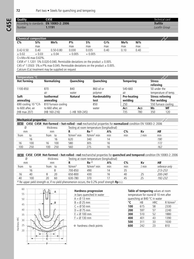
72 Part two • Steels for quenching and temperingC4
5E
Quality C45E Technical cardAccording to standards EN 10083-2: 2006 TrafilixNumber 1.1191 Lucefin Group
Temperature °C Hot forming Normalizing Quenching Quenching Tempering Stress
relieving1100-850 870 840 860 oil or 540-660 50 under the
air water polymer air temperature of temp.Soft Isothermal Natural Hardenability Pre-heating Stress relievingannealing annealing test welding fter welding690 cooling 10 °C/h 810 furnace cooling 850 250 550 furnace coolingto 600 after, air to 660 after, air water Ac1 Ac3 Ms Mf(HB max 207) (HB 160-216) (~HB 169-245) 735 780 350 120
F
CDE
B
A60
55
50
45
40
35
30
25
20Hard
ness
HRC
Table of tempering values at roomtemperature for round Ø 10 mm afterquenching at 840 °C in water°C HB HRC R N/mm2
100 615 58 2330200 597 57 2240300 510 52 1880400 401 43 1390500 311 33 1030600 242 23 810
Hardness progressionin bars quenched in waterA = Ø 13 mmB = Ø 25 mmC = Ø 50 mmD = Ø 75 mmE = Ø 100 mm F = Ø 130 mm
° hardness check points
Mechanical propertiesC45E C45R Hot-formed – hot-rolled - rod mechanichal properties for normalized condition EN 10083-2: 2006
Ø thickness Testing at room temperature (longitudinal)mm mm R Re a) A% C% Kv HB
from to from to N/mm2 min N/mm2 min min min J min min16 16 620 340 14 190
16 100 16 100 580 305 16 172100 250 100 250 560 275 16 162
C45E C45R Hot-formed – hot-rolled - rod mechanichal properties for quenched and tempered condition EN 10083-2: 2006Ø thickness Testing at room temperature (longitudinal)
mm mm R Re a) A% C% Kv HBfrom to from to N/mm2 N/mm2 min min min J min referece only
16 8 700-850 490 14 35 213-25316 40 8 20 650-800 430 16 40 25 200-24040 100 20 60 630-780 370 17 45 25 192-232
a) Re upper yield strength or, if no yield phenomenon occurs, the 0.2% proof strength Rp 0.2.
Chemical compositionC% Si% Mn% P% S% Cr% Mo% Ni%
max max max max max max0.42-0.50 0.40 0.50-0.80 0.030 0.035 0.40 0.10 0.40± 0.02 + 0.03 ± 0.04 + 0.005 + 0.005Cr+Mo+Ni max 0.63%.C45R n° 1.1201 S% 0.020-0.040. Permissible deviations on the product ± 0.005.C45 n° 1.0503 S% e P% max 0.045. Permissible deviations on the product ± 0.005.Calcium (Ca) treatment may be supplied on request
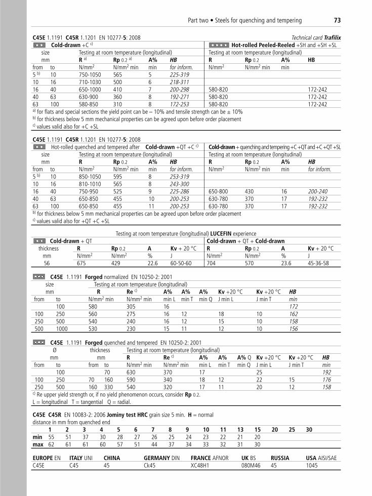
Part two • Steels for quenching and tempering 73
C45E 1.1191 C45R 1.1201 EN 10277-5: 2008 Technical card TrafilixCold-drawn +C c) Hot-rolled Peeled-Reeled +SH and +SH +SL
size Testing at room temperature (longitudinal) Testing at room temperature (longitudinal)mm R a) Rp 0.2 a) A% HB R Rp 0.2 A% HB
from to N/mm2 N/mm2 min min for inform. N/mm2 N/mm2 min min5 b) 10 750-1050 565 5 225-31910 16 710-1030 500 6 218-31116 40 650-1000 410 7 200-298 580-820 172-24240 63 630-900 360 8 192-271 580-820 172-24263 100 580-850 310 8 172-253 580-820 172-242a) for flats and special sections the yield point can be – 10% and tensile strength can be ± 10%b) for thickness below 5 mm mechanical properties can be agreed upon before order placementc) values valid also for +C +SL
C45E 1.1191 C45R 1.1201 EN 10277-5: 2008Hot-rolled quenched and tempered after Cold-drawn +QT +C c) Cold-drawn+ quenching and tempering +C +QT and +C +QT +SL
size Testing at room temperature (longitudinal) Testing at room temperature (longitudinal)mm R Rp 0.2 A% HB R Rp 0.2 A% HB
from to N/mm2 N/mm2 min min for inform. N/mm2 N/mm2 min min for inform.5 b) 10 850-1050 595 8 253-31910 16 810-1010 565 8 243-30016 40 750-950 525 9 225-286 650-800 430 16 200-24040 63 650-850 455 10 200-253 630-780 370 17 192-23263 100 650-850 455 11 200-253 630-780 370 17 192-232b) for thickness below 5 mm mechanical properties can be agreed upon before order placementc) values valid also for +QT +C +SL
Testing at room temperature (longitudinal) LUCEFIN experienceCold-drawn + QT Cold-drawn + QT + Cold-drawn
thickness R Rp 0.2 A Kv + 20 °C R Rp 0.2 A Kv + 20 °Cmm N/mm2 N/mm2 % J N/mm2 N/mm2 % J56 675 429 22.6 60-50-60 704 570 23.6 45-36-58
C45E C45R EN 10083-2: 2006 Jominy test HRC grain size 5 min. H = normaldistance in mm from quenched end
1 2 3 4 5 6 7 8 9 10 11 13 15 20 25 30 min 55 51 37 30 28 27 26 25 24 23 22 21 20max 62 61 61 60 57 51 44 37 34 33 32 31 30
EUROPE EN ITALY UNI CHINA GERMANY DIN FRANCE AFNOR UK BS RUSSIA USA AISI/SAE C45E C45 45 Ck45 XC48H1 080M46 45 1045
C45E 1.1191 Forged normalized EN 10250-2: 2001size Testing at room temperature (longitudinal)mm R Re c) A% A% A% Kv +20 °C Kv +20 °C HB
from to N/mm2 min N/mm2 min min L min T min Q J min L J min T min100 580 305 16 172
100 250 560 275 16 12 18 10 162250 500 540 240 16 12 15 10 158500 1000 530 230 15 11 12 10 156
C45E 1.1191 Forged quenched and tempered EN 10250-2: 2001Ø thickness Testing at room temperature (longitudinal)
mm mm R Re c) A% A% A% Q Kv +20 °C Kv +20 °C HBfrom to from to N/mm2 min N/mm2 min min L min T min Q J min L J min T min
100 70 630 370 17 25 192100 250 70 160 590 340 18 12 22 15 176250 500 160 330 540 320 17 11 20 12 158
c) Re upper yield strength or, if no yield phenomenon occurs, consider Rp 0.2.L = longitudinal T = tangential Q = radial.
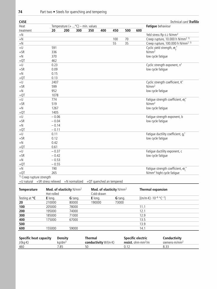
74 Part two • Steels for quenching and tempering
C45E Technical card TrafilixHeat Temperature (+ ...°C) – min. values Fatigue behaviourtreatment 20 200 300 350 400 450 500 600+N Yeld stress Rp 0.2 N/mm2
+N 100 70 Creep rupture, 10.000 h N/mm2 1)
+N 55 35 Creep rupture, 100.000 h N/mm2 1)
+U 591 Cyclic yield strength, σy′+SR 336 N/mm2
+N 370 low cycle fatigue+QT 462+U 0.23 Cyclic strength exponent, n′+SR 0.09 low cycle fatigue+N 0.15+QT 0.13+U 2407 Cyclic strength coefficient, K‘+SR 599 N/mm2
+N 952 low cycle fatigue+QT 1078+U 774 Fatigue strength coefficient, σf′+SR 519 N/mm2
+N 1267 low cycle fatigue+QT 1405+U – 0.06 Fatigue strength exponent, b+SR – 0.04 low cycle fatigue+N – 0.14+QT – 0.11+U 0.11 Fatigue ductility coefficient, gf′+SR 0.12 low cycle fatigue+N 0.42+QT 0.61+U – 0.37 Fatigue ductility exponent, c +SR – 0.42 low cycle fatigue+N – 0.53+QT – 0.55+N 190 Fatigue strength coefficient, σL′+QT 265 N/mm2 hight cycle fatigue1) Creep rupture strength+U natural +SR stress relieved +N normalized +QT quenched an tempered
Temperature Mod. of elasticity N/mm2 Mod. of elasticity N/mm2 Thermal expansionHot-rolled Cold-drawn
Testing at °C E long. G tang. E long. G tang. [(m/m·K) ·10–6 °C–1]20 210000 80000 190000 73000100 205000 78000 11.1200 195000 74000 12.1300 185000 71000 12.9400 175000 67000 13.5500 13.9600 155000 59000 14.1
Specific heat capacity Density Thermal Specific electric ConductivityJ/(kg·K) kg/dm3 conductivity W/(m·K) resist. ohm·mm2/m siemens·m/mm2
460 7.85 50 0.12 8.33
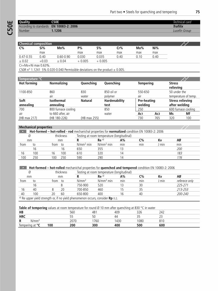
Part two • Steels for quenching and tempering 75
Quality C50E Technical cardAccording to standards EN 10083-2: 2006 TrafilixNumber 1.1206 Lucefin Group
Chemical compositionC% Si% Mn% P% S% Cr% Mo% Ni%
max max max max max max0.47-0.55 0.40 0.60-0.90 0.030 0.035 0.40 0.10 0.40± 0.02 +0.03 ± 0.04 + 0.005 + 0.005Cr+Mo+Ni max 0.63%.C50R n° 1.1241 S% 0.020-0.040 Permissible deviations on the product ± 0.005.
Temperature °C Hot forming Normalizing Quenching Quenching Tempering Stress
relieving1100-850 860 830 850 oil or 550-650 50 under the
air water polymer air temperature of temp.Soft Isothermal Natural Hardenability Pre-heating Stress relievingannealing annealing test welding after welding700 800 furnace cooling 850 250 600 furnace coolingair to 660 after, air water Ac1 Ac3 Ms Mf(HB max 217) (HB 180-226) (HB max 255) 730 765 320 100
Table of tempering values at room temperature for round Ø 10 mm after quenching at 830 °C in waterHB 560 481 409 326 242HRC 55 50 44 35 23R N/mm2 2070 1760 1430 1080 810Tempering at °C 100 200 300 400 500 600
Mechanical propertiesHot-formed – hot-rolled - rod mechanichal properties for normalized condition EN 10083-2: 2006
Ø thickness Testing at room temperature (longitudinal)mm mm R Re a) A% C% Kv HB
from to from to N/mm2 min N/mm2 min min min J min min16 16 650 355 13 200
16 100 16 100 610 320 14 183100 250 100 250 590 290 14 176
Hot-formed – hot-rolled mechanichal properties for quenched and tempered condition EN 10083-2: 2006Ø thickness Testing at room temperature (longitudinal)
mm mm R Re a) A% C% Kv HBfrom to from to N/mm2 N/mm2 min min min J min referece only
16 8 750-900 520 13 30 225-27116 40 8 20 700-850 460 15 35 213-25340 100 20 60 650-800 400 16 40 200-240
a) Re upper yield strength or, if no yield phenomenon occurs, consider Rp 0.2.
C50E
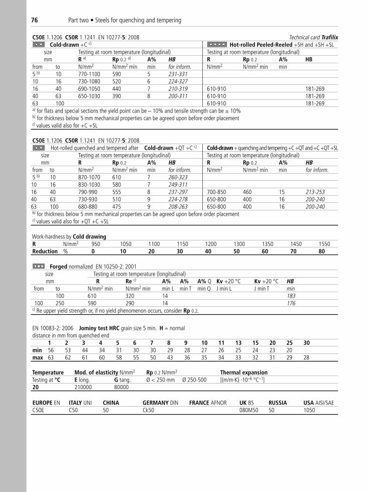
C50E 1.1206 C50R 1.1241 EN 10277-5: 2008 Technical card TrafilixCold-drawn +C c) Hot-rolled Peeled-Reeled +SH and +SH +SL
size Testing at room temperature (longitudinal) Testing at room temperature (longitudinal)mm R a) Rp 0.2 a) A% HB R Rp 0.2 A% HB
from to N/mm2 N/mm2 min min for inform. N/mm2 N/mm2 min min5 b) 10 770-1100 590 5 231-33110 16 730-1080 520 6 224-32716 40 690-1050 440 7 210-319 610-910 181-26940 63 650-1030 390 8 200-311 610-910 181-26963 100 610-910 181-269a) for flats and special sections the yield point can be – 10% and tensile strength can be ± 10%b) for thickness below 5 mm mechanical properties can be agreed upon before order placementc) values valid also for +C +SL
C50E 1.1206 C50R 1.1241 EN 10277-5: 2008Hot-rolled quenched and tempered after Cold-drawn +QT +C c) Cold-drawn+ quenching and tempering +C +QT and +C +QT +SL
size Testing at room temperature (longitudinal) Testing at room temperature (longitudinal)mm R Rp 0.2 A% HB R Rp 0.2 A% HB
from to N/mm2 N/mm2 min min for inform. N/mm2 N/mm2 min min for inform.5 b) 10 870-1070 610 7 260-32310 16 830-1030 580 7 249-31116 40 790-990 555 8 237-297 700-850 460 15 213-25340 63 730-930 510 9 224-278 650-800 400 16 200-24063 100 680-880 475 9 208-263 650-800 400 16 200-240b) for thickness below 5 mm mechanical properties can be agreed upon before order placement c) values valid also for +QT +C +SL
Work-hardness by Cold drawingR N/mm2 950 1050 1100 1150 1200 1300 1350 1450 1550Reduction % 0 10 20 30 40 50 60 70 80
EN 10083-2: 2006 Jominy test HRC grain size 5 min. H = normaldistance in mm from quenched end
1 2 3 4 5 6 7 8 9 10 11 13 15 20 25 30min 56 53 44 34 31 30 30 29 28 27 26 25 24 23 20max 63 62 61 60 58 55 50 43 36 35 34 33 32 31 29 28
Temperature Mod. of elasticity N/mm2 Rp 0.2 N/mm2 Thermal expansionTesting at °C E long. G tang. Ø < 250 mm Ø 250-500 [(m/m·K) ·10–6 °C–1]20 210000 80000
EUROPE EN ITALY UNI CHINA GERMANY DIN FRANCE AFNOR UK BS RUSSIA USA AISI/SAE C50E C50 50 Ck50 080M50 50 1050
Forged normalized EN 10250-2: 2001size Testing at room temperature (longitudinal)mm R Re c) A% A% A% Q Kv +20 °C Kv +20 °C HB
from to N/mm2 min N/mm2 min min L min T min Q J min L J min T min100 610 320 14 183
100 250 590 290 14 176c) Re upper yield strength or, if no yield phenomenon occurs, consider Rp 0.2.
76 Part two • Steels for quenching and tempering
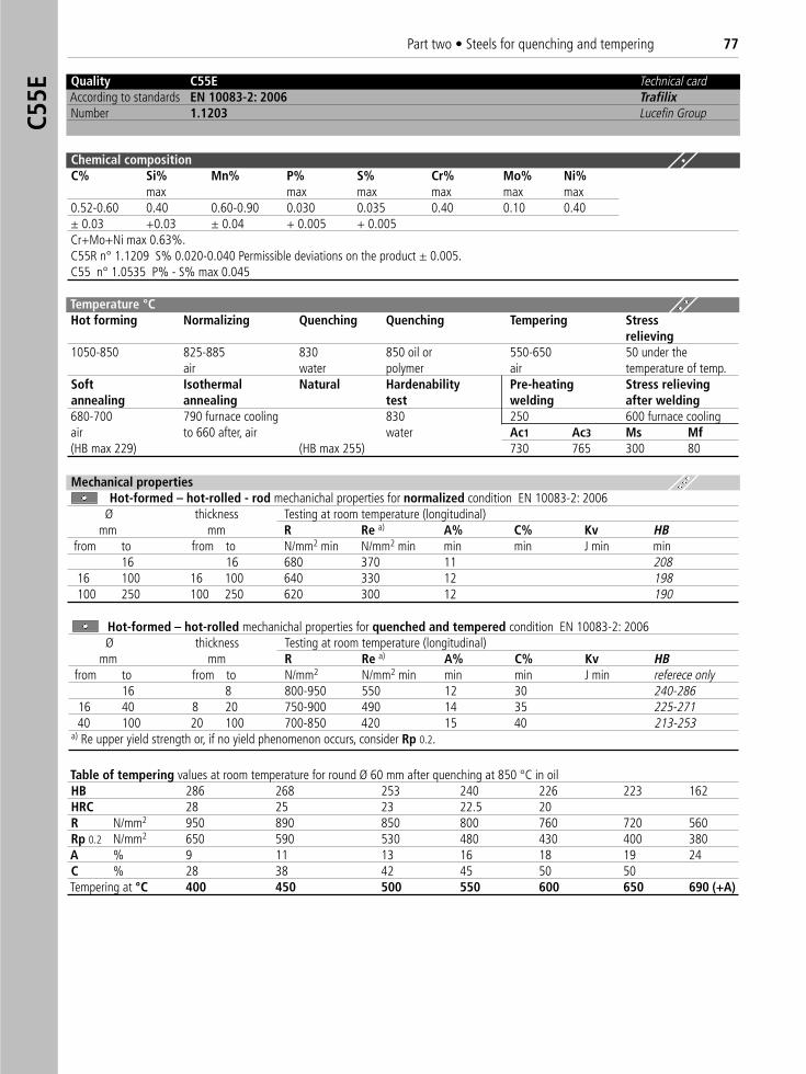
Quality C55E Technical cardAccording to standards EN 10083-2: 2006 TrafilixNumber 1.1203 Lucefin Group
Chemical compositionC% Si% Mn% P% S% Cr% Mo% Ni%
max max max max max max0.52-0.60 0.40 0.60-0.90 0.030 0.035 0.40 0.10 0.40± 0.03 +0.03 ± 0.04 + 0.005 + 0.005Cr+Mo+Ni max 0.63%.C55R n° 1.1209 S% 0.020-0.040 Permissible deviations on the product ± 0.005.C55 n° 1.0535 P% - S% max 0.045
Temperature °C Hot forming Normalizing Quenching Quenching Tempering Stress
relieving1050-850 825-885 830 850 oil or 550-650 50 under the
air water polymer air temperature of temp.Soft Isothermal Natural Hardenability Pre-heating Stress relievingannealing annealing test welding after welding680-700 790 furnace cooling 830 250 600 furnace coolingair to 660 after, air water Ac1 Ac3 Ms Mf(HB max 229) (HB max 255) 730 765 300 80
Table of tempering values at room temperature for round Ø 60 mm after quenching at 850 °C in oilHB 286 268 253 240 226 223 162HRC 28 25 23 22.5 20R N/mm2 950 890 850 800 760 720 560Rp 0.2 N/mm2 650 590 530 480 430 400 380A % 9 11 13 16 18 19 24C % 28 38 42 45 50 50Tempering at °C 400 450 500 550 600 650 690 (+A)
Mechanical propertiesHot-formed – hot-rolled - rod mechanichal properties for normalized condition EN 10083-2: 2006
Ø thickness Testing at room temperature (longitudinal)mm mm R Re a) A% C% Kv HB
from to from to N/mm2 min N/mm2 min min min J min min16 16 680 370 11 208
16 100 16 100 640 330 12 198100 250 100 250 620 300 12 190
Hot-formed – hot-rolled mechanichal properties for quenched and tempered condition EN 10083-2: 2006Ø thickness Testing at room temperature (longitudinal)
mm mm R Re a) A% C% Kv HBfrom to from to N/mm2 N/mm2 min min min J min referece only
16 8 800-950 550 12 30 240-28616 40 8 20 750-900 490 14 35 225-27140 100 20 100 700-850 420 15 40 213-253
a) Re upper yield strength or, if no yield phenomenon occurs, consider Rp 0.2.
C55E
Part two • Steels for quenching and tempering 77
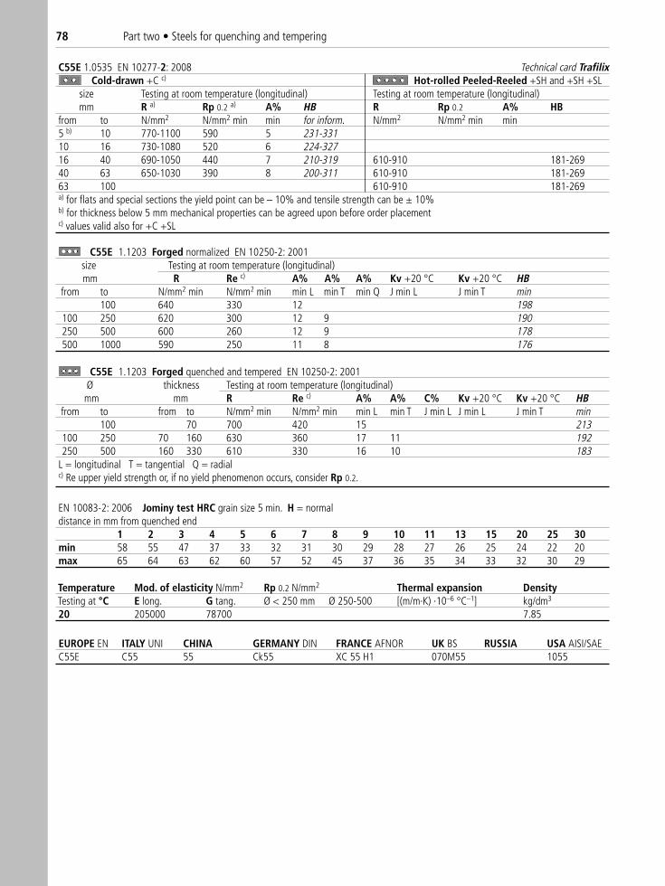
C55E 1.0535 EN 10277-2: 2008 Technical card TrafilixCold-drawn +C c) Hot-rolled Peeled-Reeled +SH and +SH +SL
size Testing at room temperature (longitudinal) Testing at room temperature (longitudinal)mm R a) Rp 0.2 a) A% HB R Rp 0.2 A% HB
from to N/mm2 N/mm2 min min for inform. N/mm2 N/mm2 min min5 b) 10 770-1100 590 5 231-33110 16 730-1080 520 6 224-32716 40 690-1050 440 7 210-319 610-910 181-26940 63 650-1030 390 8 200-311 610-910 181-26963 100 610-910 181-269a) for flats and special sections the yield point can be – 10% and tensile strength can be ± 10%b) for thickness below 5 mm mechanical properties can be agreed upon before order placementc) values valid also for +C +SL
Temperature Mod. of elasticity N/mm2 Rp 0.2 N/mm2 Thermal expansion DensityTesting at °C E long. G tang. Ø < 250 mm Ø 250-500 [(m/m·K) ·10–6 °C–1] kg/dm3
20 205000 78700 7.85
EUROPE EN ITALY UNI CHINA GERMANY DIN FRANCE AFNOR UK BS RUSSIA USA AISI/SAE C55E C55 55 Ck55 XC 55 H1 070M55 1055
C55E 1.1203 Forged normalized EN 10250-2: 2001size Testing at room temperature (longitudinal)mm R Re c) A% A% A% Kv +20 °C Kv +20 °C HB
from to N/mm2 min N/mm2 min min L min T min Q J min L J min T min100 640 330 12 198
100 250 620 300 12 9 190250 500 600 260 12 9 178500 1000 590 250 11 8 176
C55E 1.1203 Forged quenched and tempered EN 10250-2: 2001Ø thickness Testing at room temperature (longitudinal) mm mm R Re c) A% A% C% Kv +20 °C Kv +20 °C HB
from to from to N/mm2 min N/mm2 min min L min T J min L J min L J min T min100 70 700 420 15 213
100 250 70 160 630 360 17 11 192250 500 160 330 610 330 16 10 183
L = longitudinal T = tangential Q = radialc) Re upper yield strength or, if no yield phenomenon occurs, consider Rp 0.2.
EN 10083-2: 2006 Jominy test HRC grain size 5 min. H = normaldistance in mm from quenched end
1 2 3 4 5 6 7 8 9 10 11 13 15 20 25 30 min 58 55 47 37 33 32 31 30 29 28 27 26 25 24 22 20max 65 64 63 62 60 57 52 45 37 36 35 34 33 32 30 29
78 Part two • Steels for quenching and tempering
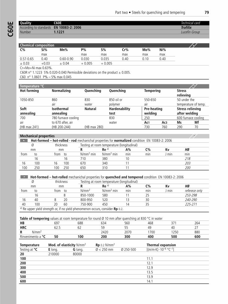
Quality C60E Technical cardAccording to standards EN 10083-2: 2006 TrafilixNumber 1.1221 Lucefin Group
Chemical compositionC% Si% Mn% P% S% Cr% Mo% Ni%
max max max max max max0.57-0.65 0.40 0.60-0.90 0.030 0.035 0.40 0.10 0.40± 0.03 +0.03 ± 0.04 + 0.005 + 0.005Cr+Mo+Ni max 0.63%.C60R n° 1.1223 S% 0.020-0.040 Permissible deviations on the product ± 0.005.C60 n° 1.0601 P% – S% max 0.045
Temperature °C Hot forming Normalizing Quenching Quenching Tempering Stress
relieving1050-850 860 830 850 oil or 550-650 50 under the
air water polymer air temperature of temp.Soft Isothermal Natural Hardenability Pre-heating Stress relievingannealing annealing test welding after welding700 780 furnace cooling 830 250 600 furnace coolingair to 670 after, air water Ac1 Ac3 Ms Mf(HB max 241) (HB 200-244) (HB max 280) 730 760 290 70
Table of tempering values at room temperature for round Ø 10 mm after quenching at 830 °C in waterHB 697 688 634 560 468 371 264HRC 62.5 62 59 55 49 40 27R N/mm2 2420 2070 1700 1250 880Rinvenimento a °C 50 100 200 300 400 500 600
Temperature Mod. of elasticity N/mm2 Rp 0.2 N/mm2 Thermal expansionTesting at °C E long. G tang. Ø < 250 mm Ø 250-500 [(m/m·K) ·10–6 °C–1]20 210000 80000100 11.1200 12.1300 12.9400 13.5500 13.9600 14.1
Mechanical propertiesHot-formed – hot-rolled - rod mechanichal properties for normalized condition EN 10083-2: 2006Ø thickness Testing at room temperature (longitudinal)mm mm R Re a) A% C% Kv HB
from to from to N/mm2 min N/mm2 min min min J min min16 16 710 380 10 218
16 100 16 100 670 340 11 203100 250 100 250 650 310 11 200
Hot-formed – hot-rolled mechanichal properties for quenched and tempered condition EN 10083-2: 2006Ø thickness Testing at room temperature (longitudinal)mm mm R Re a) A% C% Kv HB
from to from to N/mm2 N/mm2 min min min J min referece only16 8 850-1000 580 11 25 253-298
16 40 8 20 800-950 520 13 30 240-29040 100 20 60 750-900 450 14 35 225-271
a) Re upper yield strength or, if no yield phenomenon occurs, consider Rp 0.2.
Part two • Steels for quenching and tempering 79C6
0E
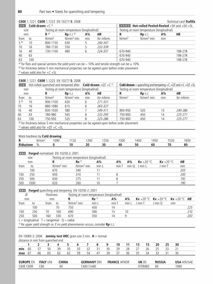
C60E 1.1221 C60R 1.1223 EN 10277-5: 2008 Technical card TrafilixCold-drawn +C c) Hot-rolled Peeled-Reeled +SH and +SH +SL
size Testing at room temperature (longitudinal) Testing at room temperature (longitudinal)mm R a) Rp 0.2 a) A% HB R Rp 0.2 A% HB
from to N/mm2 N/mm2 min min for inform. N/mm2 N/mm2 min min5 b) 10 800-1150 630 5 240-34710 16 780-1130 550 5 232-33916 40 730-1100 480 6 224-331 670-940 198-27840 63 670-940 198-27863 100 670-940 198-278a) for flats and special sections the yield point can be – 10% and tensile strength can be ± 10%b) for thickness below 5 mm mechanical properties can be agreed upon before order placementc) values valid also for +C +SL
C60E 1.1221 C60R 1.1223 EN 10277-5: 2008Hot-rolled quenched and tempered after Cold-drawn +QT +C c) Cold-drawn+ quenching and tempering +C +QT and +C +QT +SL
size Testing at room temperature (longitudinal) Testing at room temperature (longitudinal)mm R Rp 0.2 A% HB R Rp 0.2 A% HB
from to N/mm2 N/mm2 min min for inform. N/mm2 N/mm2 min min for inform.5 b) 10 900-1100 630 6 271-33110 16 880-1080 615 6 263-32716 40 830-1030 580 7 249-311 800-950 520 13 240-28640 63 780-980 545 8 232-295 750-900 450 14 225-27163 100 750-950 525 8 225-286 750-900 450 14 225-271b) for thickness below 5 mm mechanical properties can be agreed upon before order placementc) values valid also for +QT +C +SL
Work-hardness by Cold drawingR N/mm2 1090 1120 1200 1250 1300 1400 1450 1520 1650Riduzione % 0 10 20 30 40 50 60 70 80
Forged normalized EN 10250-2: 2001size Testing at room temperature (longitudinal) mm R Re c) A% A% A% Kv +20 °C Kv +20 °C HB
from to N/mm2 min N/mm2 min min L min T min Q J min L J min T min100 670 340 11 203
100 250 650 310 11 8 200250 500 630 275 11 8 192500 1000 620 260 10 7 190
Forged quenching and tempering EN 10250-2: 2001Ø thickness Testing at room temperature (longitudinal)
mm mm R Re c) A% A% Kv +20 °C Kv +20 °C Kv +20 °C HB from to from to N/mm2 min min L min T min L J min T J min Q min
100 70 750 450 14 225100 250 70 160 690 390 15 10 210250 500 160 330 670 350 14 9 203L = longitudinal T = tangential Q = radialc) Re upper yield strength or, if no yield phenomenon occurs, consider Rp 0.2.
EN 10083-2: 2006 Jominy test HRC grain size 5 min. H = normaldistance in mm from quenched end
1 2 3 4 5 6 7 8 9 10 11 13 15 20 25 30min 60 57 50 39 35 33 32 31 30 29 28 27 26 25 23 21max 67 66 65 63 62 59 54 47 39 37 36 35 34 33 31 30
EUROPE EN ITALY UNI CHINA GERMANY DIN FRANCE AFNOR UK BS RUSSIA USA AISI/SAEC60E C60R C60 60 Ck60 Cm60 070M60 60 1060
80 Part two • Steels for quenching and tempering
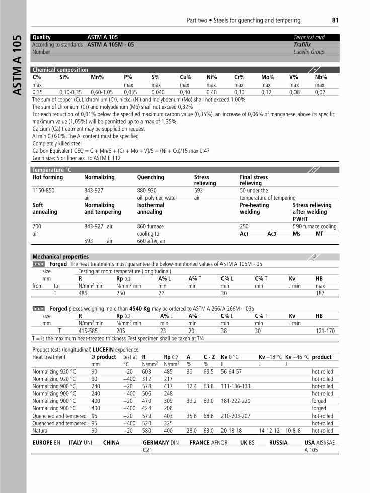
Quality ASTM A 105 Technical cardAccording to standards ASTM A 105M - 05 TrafilixNumber Lucefin Group
Chemical compositionC% Si% Mn% P% S% Cu% Ni% Cr% Mo% V% Nb%max max max max max max max max max0,35 0,10-0,35 0,60-1,05 0,035 0,040 0,40 0,40 0,30 0,12 0,08 0,02The sum of copper (Cu), chromium (Cr), nickel (Ni) and molybdenum (Mo) shall not exceed 1,00%The sum of chromium (Cr) and molybdenum (Mo) shall not exceed 0,32%For each reduction of 0,01% below the specified maximum carbon value (0,35%), an increase of 0,06% of manganese above its specific maximum value (1,05%) will be permitted up to a max of 1,35%.Calcium (Ca) treatment may be supplied on requestAl min 0,020%. The Al content must be specifiedCompletely killed steelCarbon Equivalent CEQ = C + Mn/6 + (Cr + Mo + V)/5 + (Ni + Cu)/15 max 0,47Grain size: 5 or finer acc. to ASTM E 112
Temperature °C Hot forming Normalizing Quenching Stress Final stress
relieving relieving1150-850 843-927 880-930 593 50 under the
air oil, polymer, water air temperature of temperingSoft Normalizing Isothermal Pre-heating Stress relievingannealing and tempering annealing welding after welding
PWHT700 843-927 air 860 furnace 250 590 furnace coolingair cooling to Ac1 Ac3 Ms Mf
593 air 660 after, air
Mechanical propertiesForged The heat treatments must guarantee the below-mentioned values of ASTM A 105M - 05
size Testing at room temperature (longitudinal)mm R Rp 0.2 A% L A% T C% L C% T Kv HB
from to N/mm2 min N/mm2 min min min min min J min maxT 485 250 22 30 187
Forged pieces weighing more than 4540 Kg may be ordered to ASTM A 266/A 266M – 03asize R Rp 0.2 A% L A% T C% L C% T Kv HBmm N/mm2 min N/mm2 min min min min min J min
T 415-585 205 23 20 38 30 121-170T = is the maximum heat-treated thickness. Test specimen shall be taken at T/4
Product tests (longitudinal) LUCEFIN experienceHeat treatment Ø product test at R Rp 0.2 A C - Z Kv 0 °C Kv –18 °C Kv –46 °C product
mm °C N/mm2 N/mm2 % % J J JNormalizing 920 °C 90 +20 603 485 30 69.5 56-64-57 hot-rolledNormalizing 920 °C 90 +400 312 217 hot-rolledNormalizing 900 °C 240 +20 578 417 32.4 63.8 111-136-133 hot-rolledNormalizing 900 °C 240 +400 506 248 hot-rolledNormalizing 900 °C 400 +20 470 309 39.2 69.0 181-222-220 forgedNormalizing 900 °C 400 +400 424 206 forgedQuenched and tempered 95 +20 579 403 35.6 68.6 210-203-207 hot-rolledQuenched and tempered 95 +400 520 325 hot-rolledNatural 90 +20 580 400 28.0 63.0 20-18-18 14-12-12 10-8-8 hot-rolled
EUROPE EN ITALY UNI CHINA GERMANY DIN FRANCE AFNOR UK BS RUSSIA USA AISI/SAEC21 A 105
AST
M A
105
Part two • Steels for quenching and tempering 81
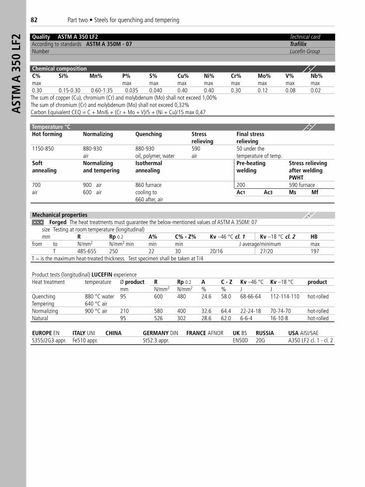
Quality ASTM A 350 LF2 Technical cardAccording to standards ASTM A 350M - 07 TrafilixNumber Lucefin Group
Chemical compositionC% Si% Mn% P% S% Cu% Ni% Cr% Mo% V% Nb%max max max max max max max max max0.30 0.15-0.30 0.60-1.35 0.035 0.040 0.40 0.40 0.30 0.12 0.08 0.02The sum of copper (Cu), chromium (Cr) and molybdenum (Mo) shall not exceed 1,00%The sum of chromium (Cr) and molybdenum (Mo) shall not exceed 0,32%Carbon Equivalent CEQ = C + Mn/6 + (Cr + Mo + V)/5 + (Ni + Cu)/15 max 0,47
Temperature °C Hot forming Normalizing Quenching Stress Final stress
relieving relieving1150-850 880-930 880-930 590 50 under the
air oil, polymer, water air temperature of temp.Soft Normalizing Isothermal Pre-heating Stress relievingannealing and tempering annealing welding after welding
PWHT700 900 air 860 furnace 200 590 furnaceair 600 air cooling to Ac1 Ac3 Ms Mf
660 after, air
Mechanical propertiesForged The heat treatments must guarantee the below-mentioned values of ASTM A 350M: 07
size Testing at room temperature (longitudinal)mm R Rp 0.2 A% C% - Z% Kv –46 °C cl. 1 Kv –18 °C cl. 2 HB
from to N/mm2 N/mm2 min min min J average/minimum maxT 485-655 250 22 30 20/16 27/20 197
T = is the maximum heat-treated thickness. Test specimen shall be taken at T/4
Product tests (longitudinal) LUCEFIN experienceHeat treatment temperature Ø product R Rp 0.2 A C - Z Kv –46 °C Kv –18 °C product
mm N/mm2 N/mm2 % % J JQuenching 880 °C water 95 600 480 24.6 58.0 68-66-64 112-114-110 hot-rolledTempering 640 °C airNormalizing 900 °C air 210 580 400 32.6 64.4 22-24-18 70-74-70 hot-rolledNatural 95 526 302 28.6 62.0 6-6-4 16-10-8 hot-rolled
EUROPE EN ITALY UNI CHINA GERMANY DIN FRANCE AFNOR UK BS RUSSIA USA AISI/SAE S355J2G3 appr. Fe510 appr. St52.3 appr. EN50D 20G A350 LF2 cl. 1 - cl. 2
AST
M A
350
LF2
82 Part two • Steels for quenching and tempering
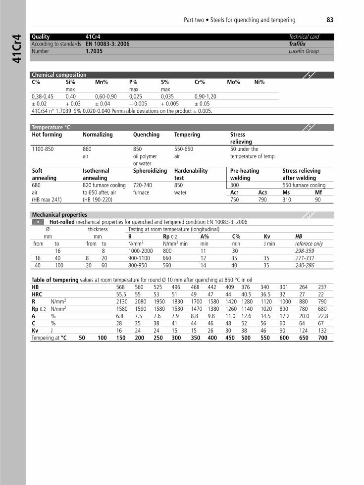
Quality 41Cr4 Technical cardAccording to standards EN 10083-3: 2006 TrafilixNumber 1.7035 Lucefin Group
Chemical compositionC% Si% Mn% P% S% Cr% Mo% Ni%
max max max0,38-0,45 0,40 0,60-0,90 0,025 0,035 0,90-1,20± 0.02 + 0.03 ± 0.04 + 0.005 + 0.005 ± 0.0541CrS4 n° 1.7039 S% 0.020-0.040 Permissible deviations on the product ± 0.005.
Temperature °C Hot forming Normalizing Quenching Tempering Stress
relieving1100-850 860 850 550-650 50 under the
air oil polymer air temperature of temp.or water
Soft Isothermal Spheroidizing Hardenability Pre-heating Stress relievingannealing annealing test welding after welding680 820 furnace cooling 720-740 850 300 550 furnace coolingair to 650 after, air furnace water Ac1 Ac3 Ms Mf(HB max 241) (HB 190-220) 750 790 310 90
Table of tempering values at room temperature for round Ø 10 mm after quenching at 850 °C in oilHB 568 560 525 496 468 442 409 376 340 301 264 237HRC 55.5 55 53 51 49 47 44 40.5 36.5 32 27 22R N/mm2 2130 2080 1950 1830 1700 1580 1420 1280 1120 1000 880 790Rp 0.2 N/mm2 1580 1590 1580 1530 1470 1380 1260 1140 1020 890 780 680A % 6.8 7.5 7.6 7.9 8.8 9.8 11.0 12.6 14.5 17.2 20.0 22.8C % 28 35 38 41 44 46 48 52 56 60 64 67Kv J 16 24 24 15 15 26 30 38 46 90 124 132Tempering at °C 50 100 150 200 250 300 350 400 450 500 550 600 650 700
Mechanical propertiesHot-rolled mechanical properties for quenched and tempered condition EN 10083-3: 2006
Ø thickness Testing at room temperature (longitudinal)mm mm R Rp 0.2 A% C% Kv HB
from to from to N/mm2 N/mm2 min min min J min referece only16 8 1000-2000 800 11 30 298-359
16 40 8 20 900-1100 660 12 35 35 271-33140 100 20 60 800-950 560 14 40 35 240-286
41Cr
4Part two • Steels for quenching and tempering 83
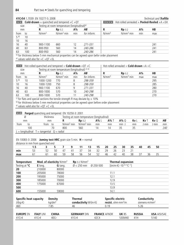
41CrS4 1.7039 EN 10277-5: 2008 Technical card TrafilixCold-drawn + quenched and tempered +C +QT Hot-rolled annealed + Peeled-Reeled +A +SH
size Testing at room temperature (longitudinal)e)
mm R Rp 0.2 A% HB R Rp 0.2 A% HBfrom to N/mm2 N/mm2 min min for inform. N/mm2 N/mm2 min min max5 b) 1010 1616 40 900-1100 660 12 271-331 24140 63 800-950 560 14 240-286 24163 100 800-950 560 14 240-286 241b) for thickness below 5 mm mechanical properties can be agreed upon befor order placemente) values valid also for +C +QT +SL
Hot-rolled quenched and tempered + Cold-drawn +QT +C Hot-rolled annealed + Cold-drawn +A +C size Testing at room temperature (longitudinal) c) e)
mm R Rp 0.2 A% HB R Rp 0.2 A% HBfrom to N/mm2 N/mm2 min min for inform. N/mm2 N/mm2 min max max5 b) 10 1000-1200 770 8 298-359 29510 16 1000-1200 750 8 298-359 28516 40 900-1100 670 9 271-331 28040 63 800-1000 570 10 240-298 27063 100 800-1000 570 11 240-298 270c) for flats and special sections the tensile strength R may deviate by ± 10%b) for thickness below 5 mm mechanical properties can be agreed upon before order placemente) values valid also for +QT +C +SL
EN 10083-3: 2006 Jominy test HRC grain size 5 min. H = normaldistance in mm from quenched end
1.5 3 5 7 9 11 13 15 20 25 30 35 40 45 50min 53 52 50 47 41 37 34 32 29 26 23 21max 61 61 60 59 58 56 54 52 46 42 40 38 37 36 35
Temperature Mod. of elasticity N/mm2 Rp 0.2 N/mm2 Thermal expansionTesting at °C E long. G tang. Ø < 250 mm Ø 250-500 [(m/m·K) ·10–6 °C–1]20 210000 80000100 205000 78000 11.1200 195000 75000 12.1300 185000 70000 12.9400 175000 67000 13.5500 13.9600 155000 59000 14.1
Specific heat capacity Density Thermal Specific electric ConductivityJ/(kg·K) kg/dm3 conductivity W/(m·K) resist. ohm·mm2/m siemens·m/mm2
460 7.85 46 0.19 5.26
EUROPE EN ITALY UNI CHINA GERMANY DIN FRANCE AFNOR UK BS RUSSIA USA AISI/SAE 41Cr4 41Cr4 40Cr 41Cr4 42C4 530M40 41H 5140
Forged quenching and tempered EN 10250-3: 2001Ø thickness Testing at room temperature (longitudinal)
mm mm R Rp 0.2 A% L A% T A% Q Kv L Kv T Kv Q HBfrom to from to N/mm2 min N/mm2 min min min min J min J min J min min
100 70 800 560 14 14 35 35 240L = longitudinal T = tangential Q = radial
84 Part two • Steels for quenching and tempering
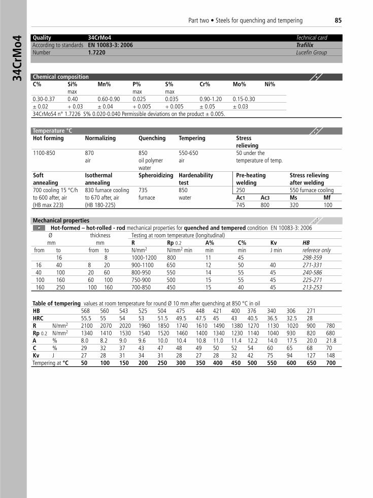
Quality 34CrMo4 Technical cardAccording to standards EN 10083-3: 2006 TrafilixNumber 1.7220 Lucefin Group
Chemical compositionC% Si% Mn% P% S% Cr% Mo% Ni%
max max max0.30-0.37 0.40 0.60-0.90 0.025 0.035 0.90-1.20 0.15-0.30± 0.02 + 0.03 ± 0.04 + 0.005 + 0.005 ± 0.05 ± 0.0334CrMoS4 n° 1.7226 S% 0.020-0.040 Permissible deviations on the product ± 0.005.
Temperature °C Hot forming Normalizing Quenching Tempering Stress
relieving1100-850 870 850 550-650 50 under the
air oil polymer air temperature of temp.water
Soft Isothermal Spheroidizing Hardenability Pre-heating Stress relievingannealing annealing test welding after welding700 cooling 15 °C/h 830 furnace cooling 735 850 250 550 furnace coolingto 600 after, air to 670 after, air furnace water Ac1 Ac3 Ms Mf(HB max 223) (HB 180-225) 745 800 320 100
Table of tempering values at room temperature for round Ø 10 mm after quenching at 850 °C in oilHB 568 560 543 525 504 475 448 421 400 376 340 306 271HRC 55.5 55 54 53 51.5 49.5 47.5 45 43 40.5 36.5 32.5 28R N/mm2 2100 2070 2020 1960 1850 1740 1610 1490 1380 1270 1130 1020 900 780Rp 0.2 N/mm2 1340 1410 1530 1540 1520 1460 1400 1340 1230 1140 1040 930 820 680A % 8.0 8.2 9.0 9.6 10.0 10.4 10.8 11.0 11.4 12.2 14.0 17.5 20.0 21.8C % 29 32 37 43 47 48 49 50 52 54 60 65 68 70Kv J 27 28 31 34 31 28 27 28 32 42 75 94 127 148Tempering at °C 50 100 150 200 250 300 350 400 450 500 550 600 650 700
Mechanical propertiesHot-formed – hot-rolled - rod mechanical properties for quenched and tempered condition EN 10083-3: 2006
Ø thickness Testing at room temperature (longitudinal)mm mm R Rp 0.2 A% C% Kv HB
from to from to N/mm2 N/mm2 min min min J min referece only16 8 1000-1200 800 11 45 298-359
16 40 8 20 900-1100 650 12 50 40 271-33140 100 20 60 800-950 550 14 55 45 240-586100 160 60 100 750-900 500 15 55 45 225-271160 250 100 160 700-850 450 15 40 45 213-253
34Cr
Mo4
Part two • Steels for quenching and tempering 85
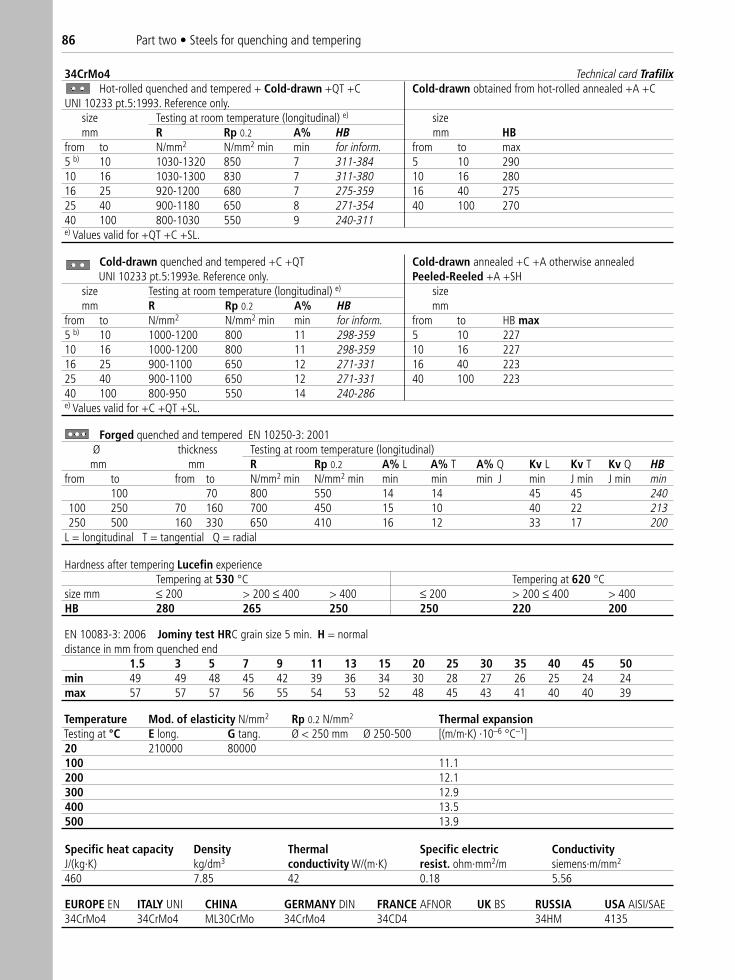
34CrMo4 Technical card TrafilixHot-rolled quenched and tempered + Cold-drawn +QT +C Cold-drawn obtained from hot-rolled annealed +A +C
UNI 10233 pt.5:1993. Reference only.size Testing at room temperature (longitudinal) e) sizemm R Rp 0.2 A% HB mm HB
from to N/mm2 N/mm2 min min for inform. from to max5 b) 10 1030-1320 850 7 311-384 5 10 29010 16 1030-1300 830 7 311-380 10 16 28016 25 920-1200 680 7 275-359 16 40 27525 40 900-1180 650 8 271-354 40 100 27040 100 800-1030 550 9 240-311e) Values valid for +QT +C +SL.
Hardness after tempering Lucefin experienceTempering at 530 °C Tempering at 620 °C
size mm ≤ 200 > 200 ≤ 400 > 400 ≤ 200 > 200 ≤ 400 > 400HB 280 265 250 250 220 200
EN 10083-3: 2006 Jominy test HRC grain size 5 min. H = normaldistance in mm from quenched end
1.5 3 5 7 9 11 13 15 20 25 30 35 40 45 50min 49 49 48 45 42 39 36 34 30 28 27 26 25 24 24max 57 57 57 56 55 54 53 52 48 45 43 41 40 40 39
Temperature Mod. of elasticity N/mm2 Rp 0.2 N/mm2 Thermal expansionTesting at °C E long. G tang. Ø < 250 mm Ø 250-500 [(m/m·K) ·10–6 °C–1]20 210000 80000100 11.1200 12.1300 12.9400 13.5500 13.9
Specific heat capacity Density Thermal Specific electric ConductivityJ/(kg·K) kg/dm3 conductivity W/(m·K) resist. ohm·mm2/m siemens·m/mm2
460 7.85 42 0.18 5.56
EUROPE EN ITALY UNI CHINA GERMANY DIN FRANCE AFNOR UK BS RUSSIA USA AISI/SAE 34CrMo4 34CrMo4 ML30CrMo 34CrMo4 34CD4 34HM 4135
Forged quenched and tempered EN 10250-3: 2001Ø thickness Testing at room temperature (longitudinal)
mm mm R Rp 0.2 A% L A% T A% Q Kv L Kv T Kv Q HBfrom to from to N/mm2 min N/mm2 min min min min J min J min J min min
100 70 800 550 14 14 45 45 240100 250 70 160 700 450 15 10 40 22 213250 500 160 330 650 410 16 12 33 17 200
L = longitudinal T = tangential Q = radial
Cold-drawn quenched and tempered +C +QT Cold-drawn annealed +C +A otherwise annealed �UNI 10233 pt.5:1993e. Reference only. Peeled-Reeled +A +SH
size Testing at room temperature (longitudinal) e) sizemm R Rp 0.2 A% HB mm
from to N/mm2 N/mm2 min min for inform. from to HB max5 b) 10 1000-1200 800 11 298-359 5 10 22710 16 1000-1200 800 11 298-359 10 16 22716 25 900-1100 650 12 271-331 16 40 22325 40 900-1100 650 12 271-331 40 100 22340 100 800-950 550 14 240-286e) Values valid for +C +QT +SL.
86 Part two • Steels for quenching and tempering
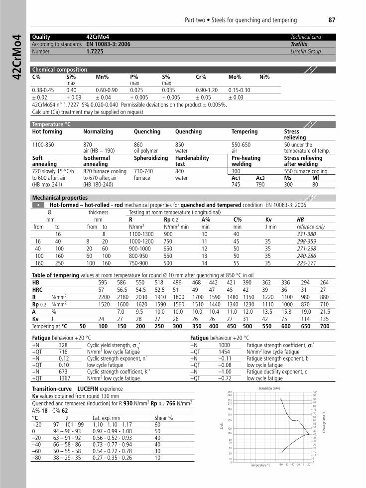
Quality 42CrMo4 Technical cardAccording to standards EN 10083-3: 2006 TrafilixNumber 1.7225 Lucefin Group
Chemical compositionC% Si% Mn% P% S% Cr% Mo% Ni%
max max max0.38-0.45 0.40 0.60-0.90 0.025 0.035 0.90-1.20 0.15-0.30± 0.02 + 0.03 ± 0.04 + 0.005 + 0.005 ± 0.05 ± 0.0342CrMoS4 n° 1.7227 S% 0.020-0.040 Permissible deviations on the product ± 0.005%.Calcium (Ca) treatment may be supplied on request
Temperature °C Hot forming Normalizing Quenching Quenching Tempering Stress
relieving1100-850 870 860 850 550-650 50 under the
air (HB ~ 190) oil polymer water air temperature of temp.Soft Isothermal Spheroidizing Hardenability Pre-heating Stress relievingannealing annealing test welding after welding720 slowly 15 °C/h 820 furnace cooling 730-740 840 300 550 furnace coolingto 600 after, air to 670 after, air furnace water Ac1 Ac3 Ms Mf(HB max 241) (HB 180-240) 745 790 300 80
Table of tempering values at room temperature for round Ø 10 mm after quenching at 850 °C in oil HB 595 586 550 518 496 468 442 421 390 362 336 294 264HRC 57 56.5 54.5 52.5 51 49 47 45 42 39 36 31 27R N/mm2 2200 2180 2030 1910 1800 1700 1590 1480 1350 1220 1100 980 880Rp 0.2 N/mm2 1520 1600 1620 1590 1560 1510 1440 1340 1230 1110 1000 870 710A % 7.0 9.5 10.0 10.0 10.0 10.4 11.0 12.0 13.5 15.8 19.0 21.5Kv J 24 27 28 27 26 26 26 27 31 42 75 114 135Tempering at °C 50 100 150 200 250 300 350 400 450 500 550 600 650 700
Fatigue behaviour +20 °C Fatigue behaviour +20 °C+N 328 Cyclic yield strength, σ y’ +N 1000 Fatigue strength coefficient, σf‘+QT 716 N/mm2 low cycle fatigue +QT 1454 N/mm2 low cycle fatigue+N 0.12 Cyclic strength exponent, n’ +N –0.11 Fatigue strength exponent, b+QT 0.10 low cycle fatigue +QT –0.08 low cycle fatigue+N 673 Cyclic strength coefficient, K ‘ +N –1.00 Fatigue ductility exponent, c +QT 1367 N/mm2 low cycle fatigue +QT –0.72 low cycle fatigue
Mechanical propertiesHot-formed – hot-rolled - rod mechanical properties for quenched and tempered condition EN 10083-3: 2006
Ø thickness Testing at room temperature (longitudinal) mm mm R Rp 0.2 A% C% Kv HB
from to from to N/mm2 N/mm2 min min min J min referece only16 8 1100-1300 900 10 40 331-380
16 40 8 20 1000-1200 750 11 45 35 298-35940 100 20 60 900-1000 650 12 50 35 271-298100 160 60 100 800-950 550 13 50 35 240-286160 250 100 160 750-900 500 14 55 35 225-271
Joul
e
Clea
vage
are
a %
TRANSITION CURVE
8085
100
75
6560
40
30
2520
50
15
9590
70
55
10
45
50
35
200–20–40–60–80
220
240250
210
190
170
150
120
100
8070
50
30
100
Temperature °C
Transition-curve LUCEFIN experienceKv values obtained from round 130 mm Quenched and tempered (induction) for R 930 N/mm2 Rp 0.2 766 N/mm2
A% 18 - C% 62°C J Lat. exp. mm Shear %+20 97 – 101 - 99 1.10 - 1.10 - 1.17 600 94 – 96 - 93 0.97 - 0.99 - 1.00 50–20 63 – 91 - 92 0.56 - 0.52 - 0.93 40–40 66 – 58 - 86 0.73 - 0.77 - 0.94 40–60 50 – 55 - 58 0.54 - 0.72 - 0.78 30–80 38 – 29 - 35 0.27 - 0.35 - 0.26 10
42Cr
Mo4
Part two • Steels for quenching and tempering 87
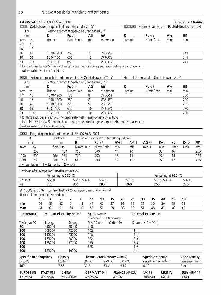
42CrMoS4 1.7227 EN 10277-5: 2008 Technical card TrafilixCold-drawn + quenched and tempered +C +QT Hot-rolled annealed + Peeled-Reeled +A +SH
size Testing at room temperature (longitudinal) e)
mm R Rp 0.2 A% HB R Rp 0.2 A% HBfrom to N/mm2 N/mm2 min min for inform. N/mm2 N/mm2 min min max5 b) 1010 1616 40 1000-1200 750 11 298-359 24140 63 900-1100 650 12 271-331 24163 100 900-1100 650 12 271-331 241b) for thickness below 5 mm mechanical properties can be agreed upon before order placemente) values valid also for +C +QT +SL
Hot-rolled quenched and tempered after Cold-drawn +QT +C Hot-rolled annealed + Cold-drawn +A +Csize Testing at room temperature (longitudinal) c) e)
mm R Rp 0.2 A% HB R Rp 0.2 A% HBfrom to N/mm2 N/mm2 min min for inform. N/mm2 N/mm2 min min max5 b) 10 1000-1200 770 8 298-359 30010 16 1000-1200 750 8 298-359 29016 40 1000-1200 720 9 298-359 28540 63 900-1100 650 10 271-331 28063 100 900-1100 650 10 271-331 280c) for flats and special sections the tensile strength R may deviate by ± 10%b) for thickness below 5 mm mechanical properties can be agreed upon before order placemente) values valid also for +QT +C +SL
Hardness after tempering Lucefin experienceTempering at 530 °C Tempering at 620 °C
size mm ≤ 200 > 200 ≤ 400 > 400 ≤ 200 > 200 ≤ 400 > 400HB 320 300 290 260 250 230
EN 10083-3: 2006 Jominy test HRC grain size 5 min. H = normaldistance in mm from quenched end
1.5 3 5 7 9 11 13 15 20 25 30 35 40 45 50min 53 53 52 51 49 43 40 37 34 32 31 30 30 29 29max 61 61 61 60 60 59 59 58 56 53 51 48 47 46 45
Specific heat capacity Density Thermal conductivity W/(m·K) Specific electric ConductivityJ/(kg·K) kg/dm3 20 °C 250 °C 500 °C resist. ohm·mm2/m siemens·m/mm2
460 7.85 33.5 34.0 34.2 0.19 5.26
EUROPE EN ITALY UNI CHINA GERMANY DIN FRANCE AFNOR UK BS RUSSIA USA AISI/SAE 42CrMo4 42CrMo4 ML42CrMo 42CrMo4 42CD4 708M40 42HM 4140
Forged quenched and tempered EN 10250-3: 2001Ø thickness Testing at room temperature (longitudinal)mm mm R Rp 0.2 A% L A% T A% Q Kv L Kv T Kv Q HB
from to from to N/mm2 min N/mm2 min min min min J min J min J min min250 160 750 500 14 10 30 16 225
250 500 160 330 700 460 15 11 27 14 213500 750 330 500 600 390 16 12 22 12 178
L = longitudinal T = tangential Q = radial
Temperature Mod. of elasticity N/mm2 Rp 0.2 N/mm2 Thermal expansionquenching and tempering
Testing at °C E long. G tang. Ø < 60 mm Ø 60-150 [(m/m·K) ·10–6 °C–1]20 210000 80000 720100 205000 78000 702 11.1200 195000 75000 640 12.1300 185000 70000 562 12.9400 175000 67000 475 13.5500 375 13.9600 155000 59000 14.1
88 Part two • Steels for quenching and tempering
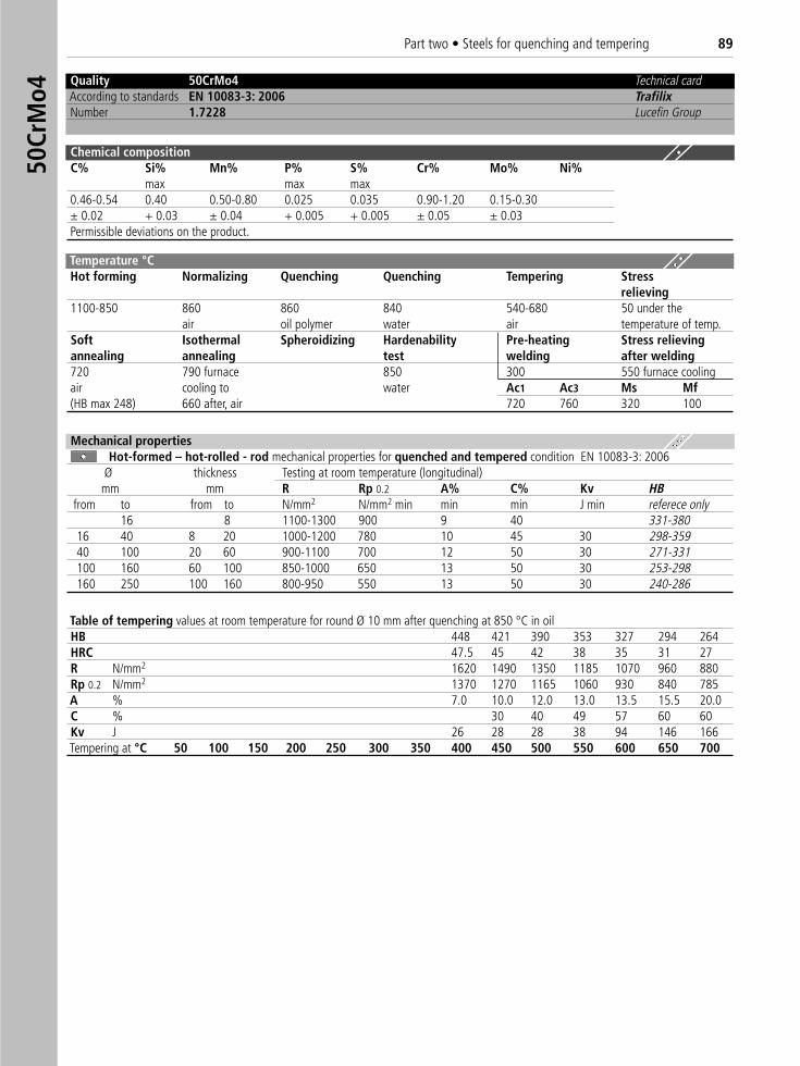
Quality 50CrMo4 Technical cardAccording to standards EN 10083-3: 2006 TrafilixNumber 1.7228 Lucefin Group
Chemical compositionC% Si% Mn% P% S% Cr% Mo% Ni%
max max max0.46-0.54 0.40 0.50-0.80 0.025 0.035 0.90-1.20 0.15-0.30± 0.02 + 0.03 ± 0.04 + 0.005 + 0.005 ± 0.05 ± 0.03Permissible deviations on the product.
Temperature °C Hot forming Normalizing Quenching Quenching Tempering Stress
relieving1100-850 860 860 840 540-680 50 under the
air oil polymer water air temperature of temp.Soft Isothermal Spheroidizing Hardenability Pre-heating Stress relievingannealing annealing test welding after welding720 790 furnace 850 300 550 furnace coolingair cooling to water Ac1 Ac3 Ms Mf(HB max 248) 660 after, air 720 760 320 100
Table of tempering values at room temperature for round Ø 10 mm after quenching at 850 °C in oilHB 448 421 390 353 327 294 264HRC 47.5 45 42 38 35 31 27R N/mm2 1620 1490 1350 1185 1070 960 880Rp 0.2 N/mm2 1370 1270 1165 1060 930 840 785A % 7.0 10.0 12.0 13.0 13.5 15.5 20.0C % 30 40 49 57 60 60Kv J 26 28 28 38 94 146 166Tempering at °C 50 100 150 200 250 300 350 400 450 500 550 600 650 700
Mechanical propertiesHot-formed – hot-rolled - rod mechanical properties for quenched and tempered condition EN 10083-3: 2006
Ø thickness Testing at room temperature (longitudinal)mm mm R Rp 0.2 A% C% Kv HB
from to from to N/mm2 N/mm2 min min min J min referece only16 8 1100-1300 900 9 40 331-380
16 40 8 20 1000-1200 780 10 45 30 298-35940 100 20 60 900-1100 700 12 50 30 271-331100 160 60 100 850-1000 650 13 50 30 253-298160 250 100 160 800-950 550 13 50 30 240-286
50Cr
Mo4
Part two • Steels for quenching and tempering 89
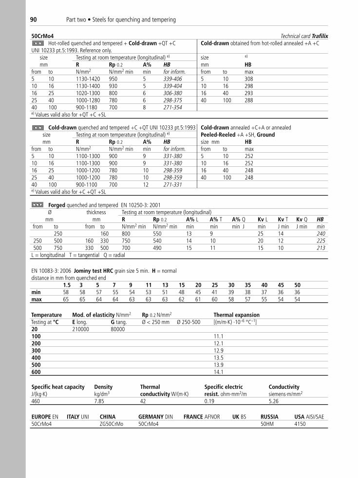
50CrMo4 Technical card TrafilixHot-rolled quenched and tempered + Cold-drawn +QT +C Cold-drawn obtained from hot-rolled annealed +A +C
UNI 10233 pt.5:1993. Reference only.size Testing at room temperature (longitudinal) e) size e)
mm R Rp 0.2 A% HB mm HBfrom to N/mm2 N/mm2 min min for inform. from to max5 10 1130-1420 950 5 339-406 5 10 30810 16 1130-1400 930 5 339-404 10 16 29816 25 1020-1300 800 6 306-380 16 40 29325 40 1000-1280 780 6 298-375 40 100 28840 100 900-1180 700 8 271-354e) Values valid also for +QT +C +SL
Cold-drawn quenched and tempered +C +QT UNI 10233 pt.5:1993 Cold-drawn annealed +C+A or annealedsize Testing at room temperature (longitudinal) e) Peeled-Reeled +A +SH, Groundmm R Rp 0.2 A% HB size mm HB
from to N/mm2 N/mm2 min min for inform. from to max5 10 1100-1300 900 9 331-380 5 10 25210 16 1100-1300 900 9 331-380 10 16 25216 25 1000-1200 780 10 298-359 16 40 24825 40 1000-1200 780 10 298-359 40 100 24840 100 900-1100 700 12 271-331e) Values valid also for +C +QT +SL
EN 10083-3: 2006 Jominy test HRC grain size 5 min. H = normaldistance in mm from quenched end
1.5 3 5 7 9 11 13 15 20 25 30 35 40 45 50min 58 58 57 55 54 53 51 48 45 41 39 38 37 36 36max 65 65 64 64 63 63 63 62 61 60 58 57 55 54 54
Temperature Mod. of elasticity N/mm2 Rp 0.2 N/mm2 Thermal expansionTesting at °C E long. G tang. Ø < 250 mm Ø 250-500 [(m/m·K) ·10–6 °C–1]20 210000 80000100 11.1200 12.1300 12.9400 13.5500 13.9600 14.1
Specific heat capacity Density Thermal Specific electric ConductivityJ/(kg·K) kg/dm3 conductivity W/(m·K) resist. ohm·mm2/m siemens·m/mm2
460 7.85 42 0.19 5.26
EUROPE EN ITALY UNI CHINA GERMANY DIN FRANCE AFNOR UK BS RUSSIA USA AISI/SAE50CrMo4 ZG50CrMo 50CrMo4 50HM 4150
Forged quenched and tempered EN 10250-3: 2001Ø thickness Testing at room temperature (longitudinal)
mm mm R Rp 0.2 A% L A% T A% Q Kv L Kv T Kv Q HBfrom to from to N/mm2 min N/mm2 min min min min J min J min J min min
250 160 800 550 13 9 25 14 240250 500 160 330 750 540 14 10 20 12 225500 750 330 500 700 490 15 11 15 10 213
L = longitudinal T = tangential Q = radial
90 Part two • Steels for quenching and tempering
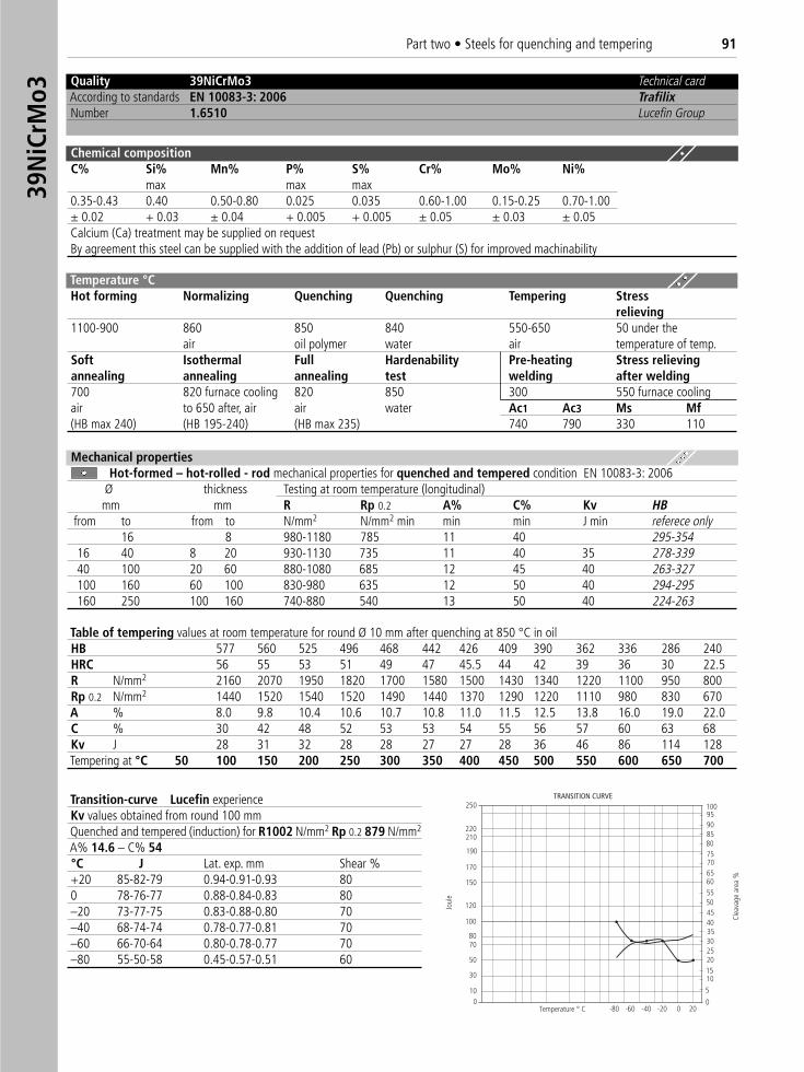
Quality 39NiCrMo3 Technical cardAccording to standards EN 10083-3: 2006 TrafilixNumber 1.6510 Lucefin Group
Chemical compositionC% Si% Mn% P% S% Cr% Mo% Ni%
max max max0.35-0.43 0.40 0.50-0.80 0.025 0.035 0.60-1.00 0.15-0.25 0.70-1.00± 0.02 + 0.03 ± 0.04 + 0.005 + 0.005 ± 0.05 ± 0.03 ± 0.05Calcium (Ca) treatment may be supplied on requestBy agreement this steel can be supplied with the addition of lead (Pb) or sulphur (S) for improved machinability
Temperature °CHot forming Normalizing Quenching Quenching Tempering Stress
relieving1100-900 860 850 840 550-650 50 under the
air oil polymer water air temperature of temp.Soft Isothermal Full Hardenability Pre-heating Stress relievingannealing annealing annealing test welding after welding700 820 furnace cooling 820 850 300 550 furnace coolingair to 650 after, air air water Ac1 Ac3 Ms Mf(HB max 240) (HB 195-240) (HB max 235) 740 790 330 110
Table of tempering values at room temperature for round Ø 10 mm after quenching at 850 °C in oilHB 577 560 525 496 468 442 426 409 390 362 336 286 240HRC 56 55 53 51 49 47 45.5 44 42 39 36 30 22.5R N/mm2 2160 2070 1950 1820 1700 1580 1500 1430 1340 1220 1100 950 800Rp 0.2 N/mm2 1440 1520 1540 1520 1490 1440 1370 1290 1220 1110 980 830 670A % 8.0 9.8 10.4 10.6 10.7 10.8 11.0 11.5 12.5 13.8 16.0 19.0 22.0C % 30 42 48 52 53 53 54 55 56 57 60 63 68Kv J 28 31 32 28 28 27 27 28 36 46 86 114 128Tempering at °C 50 100 150 200 250 300 350 400 450 500 550 600 650 700
Transition-curve Lucefin experienceKv values obtained from round 100 mm Quenched and tempered (induction) for R1002 N/mm2 Rp 0.2 879 N/mm2
A% 14.6 – C% 54°C J Lat. exp. mm Shear %+20 85-82-79 0.94-0.91-0.93 800 78-76-77 0.88-0.84-0.83 80–20 73-77-75 0.83-0.88-0.80 70–40 68-74-74 0.78-0.77-0.81 70–60 66-70-64 0.80-0.78-0.77 70–80 55-50-58 0.45-0.57-0.51 60
Joul
e
Clea
vage
are
a %
TRANSITION CURVE
8085
100
75
6560
40
302520
50
15
9590
70
55
10
45
5
0
35
200-20-40-60-80
210220
250
190
170
150
120
100
8070
50
30
100
Mechanical propertiesHot-formed – hot-rolled - rod mechanical properties for quenched and tempered condition EN 10083-3: 2006
Ø thickness Testing at room temperature (longitudinal)mm mm R Rp 0.2 A% C% Kv HB
from to from to N/mm2 N/mm2 min min min J min referece only16 8 980-1180 785 11 40 295-354
16 40 8 20 930-1130 735 11 40 35 278-33940 100 20 60 880-1080 685 12 45 40 263-327100 160 60 100 830-980 635 12 50 40 294-295160 250 100 160 740-880 540 13 50 40 224-263
39N
iCrM
o3Part two • Steels for quenching and tempering 91
39NiCrMo3 1.6510 EN 10277-5: 2008 Technical card TrafilixCold-drawn + quenched and tempered +C +QT Hot-rolled annealed + Peeled-Reeled +A +SH
size Testing at room temperature (longitudinal) e)
mm R Rp 0.2 A% HB R Rp 0.2 A% HBfrom to N/mm2 N/mm2 min min for inform. N/mm2 min N/mm2 min min max5 b) 1010 1616 40 930-1130 735 11 278-339 24040 63 880-1080 735 12 263-327 24063 100 880-1080 735 12 263-327 240b) for thickness below 5 mm mechanical properties can be agreed upon before order placemente) values valid also for +C +QT +SL
Hot-rolled quenched and tempered + Cold-drawn +QT +C Hot-rolled annealed + Ground +A +C size Testing at room temperature (longitudinal) c) e)
mm R Rp 0.2 A% HB R Rp 0.2 A% HBfrom to N/mm2 N/mm2 min min for inform. N/mm2 min N/mm2 min min max5 b) 10 980-1180 735 8 295-354 29510 16 930-1130 700 8 278-339 29016 40 930-1130 700 9 278-339 28540 63 880-1080 625 10 263-327 28063 100 880-1080 600 10 263-327 280c) for flats and special sections the tensile strength R may deviate by ± 10%b) for thickness below 5 mm mechanical properties can be agreed upon before order placemente) values valid also for QT +C +SL
Forged quenched and tempered UNI 7874: 1979. Reference only.size Testing at room temperature (longitudinal)mm R Rp 0.2 A% L A% T Kv L Kv T HB
from to N/mm2 N/mm2 min min min J min J min100 880-1080 685 12 40 263-327
100 250 685-835 540 13 12 30 25 209-250250 500 655-805 490 15 14 30 25 201-241500 1000 635-785 440 16 15 25 195-2341000 590-740 390 15 14 25 176-224L = longitudinal T = tangential
EN 10083-3: 2006 Jominy test HRC grain size 5 min. H = normaldistance in mm from quenched end
1.5 3 5 7 9 11 13 15 20 25 30 35 40 45 50min 52 51 50 49 48 46 44 43 39 36 34 33 32 31 30max 60 60 59 58 58 57 57 56 55 52 51 49 48 46 45
Temperature Mod. of elasticity N/mm2 Rp 0.2 N/mm2 Thermal expansion DensityTesting at °C E long. G tang. Ø < 250 mm Ø 250-500 [(m/m·K) ·10–6 °C–1] kg/dm3
20 210000 80000 11.2 7.80
EUROPE EN ITALY UNI CHINA GERMANY DIN FRANCE AFNOR UK BS RUSSIA USA AISI/SAE39NiCrMo3 39NiCrMo3 36CrNiMo4 40NCD3 39HNM 9840
92 Part two • Steels for quenching and tempering
Quality 34CrNiMo6 Technical cardAccording to standards EN 10083-3: 2006 TrafilixNumber 1.6582 Lucefin Group
Chemical compositionC% Si% Mn% P% S% Cr% Mo% Ni%
max max max0.30-0.38 0.40 0.50-0.80 0.035 0.035 1.30-1.70 0.15-0.30 1.30-1.70± 0.02 + 0.03 ± 0.04 + 0.005 + 0.005 ± 0.05 ± 0.03 ± 0.05Permissible deviations on the product.
Temperature °C Hot forming Normalizing Quenching Quenching Tempering Stress
relieving1100-900 860-870 870 860 600-650 50 under the
air oil polymer water air temperature of temp.Soft Isothermal Full Hardenability Pre-heating Stress relievingannealing annealing annealing test welding after welding650-680 650 cooling 850 300 600 furnace coolingair furnace to water Ac1 Ac3 Ms Mf(HB max 248) 500 after, air 715 770 320 100
Table of tempering values at room temperature for round Ø 60 mm after quenching at 850 °C in oilHB 525 500 468 450 371 344 319 271 240HRC 53 51.5 49 46.5 40 37 34 28 22R N/mm2 1950 1850 1700 1500 1260 1150 1050 900 800Rp 0.2 N/mm2 1450 1480 1450 1350 1980 980 950 700 680A % 10 10 10 12 13 13.4 18 20 22C % 48 50 52 58 62 62 68 68 70Kv JTempering at °C 100 200 300 400 500 550 600 650 700
LUCEFIN experience Forged round 520 mm quenched at 870 °C in water, tempered at 630 °C in airDepth from Longitudinal Testingtreated R Rp 0.2 A C Kv +20 °C Kv –40 °C HBsurface N/mm2 N/mm2 % % J T 25 mm 920 820 18.5 64.0 110-118-118 2801/3 radius 900 755 15.6 60.0 48-44-45 2701/2 diameter 870 730 12.8 46.0 70-74-68 25-28-25 262FATT (Fracture Appearance Transition Temperature)°C –70 –60 –40 –20 0 +20 +50 +80 +18% fibrosity 3 6 11 15 24 53 100 100 FATT 50Kv average J 22 24 27 42 51 70 142 150 68Chemical composition % ppmC Si Mn P S Cr Mo Ni V Cu Sn As Sb Al H2 O2 N20.35 0.24 0.61 0.007 0.002 1.65 0.28 1.68 0.06 0.13 0.006 0.007 0.004 0.014 1.30 32 70
Mechanical propertiesHot-formed – hot-rolled - rod mechanical properties for quenched and tempered condition EN 10083-3: 2006
Ø thickness Testing at room temperature (longitudinal)mm mm R Rp 0.2 A% C% Kv HB
from to from to N/mm2 N/mm2 min min min J min referece only16 8 1200-1400 1000 9 40 359-404
16 40 8 20 1100-1300 900 10 45 45 331-38040 100 20 60 1000-1200 800 11 50 45 298-359100 160 60 100 900-1100 700 12 55 45 271-331160 250 100 160 800-950 600 13 55 45 240-286
34Cr
NiM
o6Part two • Steels for quenching and tempering 93
34CrNiMo6 1.6582 EN 10277-5: 2008 Technical card TrafilixHot-rolled quenched and tempered + Cold-drawn +QT +C Cold-drawn obtained from hot-rolled annealed +A +C
size Testing at room temperature (longitudinal) e)
mm R Rp 0.2 A% HB HBfrom to N/mm2 N/mm2 min min for inform. max5 b) 10 1000-1200 770 8 298-359 30810 16 1000-1200 750 8 298-359 29816 40 1000-1200 720 9 298-359 29340 63 1000-1200 650 10 298-359 28863 100 1000-1200 650 10 298-359 288b) for thickness below 5 mm mechanical properties can be agreed upon before order placemente) values valid also for +QT +C +SL
Cold-drawn quenched and tempered +C +QT As rolled + turned +SH or annealing Peeled-Reeled +A +SHsize Testing at room temperature (longitudinal) c) e) Ground +SLmm R Rp 0.2 A% HB HB
from to N/mm2 N/mm2 min min for inform. max5 b) 1010 1616 40 1100-1300 900 10 331-380 24840 63 1000-1200 800 11 298-359 24863 100 1000-1200 800 11 298-359 248c) for flats and special sections the tensile strength R may deviate by ± 10% b) for thickness below 5 mm mechanical properties can be agreed upon before order placement e) values valid also for +C +QT +SL
EN 10083-3: 2006 Jominy test HRC grain size 5 min. H = normaldistance in mm from quenched end
1.5 3 5 7 9 11 13 15 20 25 30 35 40 45 50min 50 50 50 50 49 48 48 48 48 47 47 47 46 45 44max 58 58 58 58 57 57 57 57 57 57 57 57 57 57 57
Temperature Mod. of elasticity N/mm2 Rp 0.2 N/mm2 Thermal expansionTesting at °C E long. G tang. Ø < 250 mm Ø 250-500 [(m/m·K) ·10–6 °C–1]20 210000 80000100 205000 78000 11.1200 195000 75000 12.1300 185000 70000 12.9400 175000 67000 13.5500 13.9600 14.1
Specific heat capacity Density Thermal Specific electric ConductivityJ/(kg·K) kg/dm3 conductivity W/(m·K) resist. ohm·mm2/m siemens·m/mm2
460 7.85 38 0.19 5.26
Minimum service temperature Maximum service temperature –40 °C to max –70 °C +600 °C to max +650 °C
Corrosion resistance Cold workingSteel with low resistance to corrosion This steel may be cold worked in the annealed condition.A protective coating should be used It has a good ductility
EUROPE EN ITALY UNI CHINA GERMANY DIN FRANCE AFNOR UK BS RUSSIA USA AISI/SAE 34CrNiMo6 35NiCrMo6 34CrNiMo6 35NCD6 817M40 38Ch2N2MA 4340
Forged quenched and tempered EN 10250-3: 2001Ø thickness Testing at room temperature (longitudinal)
mm mm R Rp 0.2 A% L A% T A% Q Kv L Kv T Kv Q HBfrom to from to N/mm2 min N/mm2 min min min min J min J min J min min
250 160 800 600 13 9 45 22 240250 500 160 330 750 540 14 10 45 22 225500 990 330 660 700 490 15 11 40 20 213
L = longitudinal T = tangential Q = radial
94 Part two • Steels for quenching and tempering
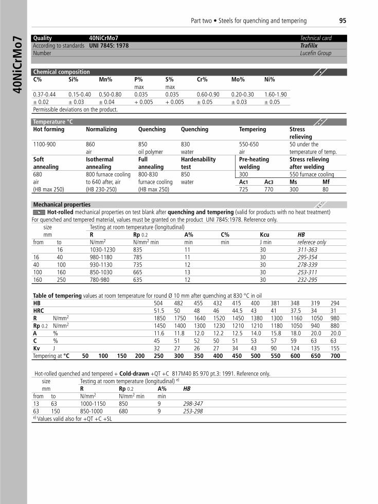
Quality 40NiCrMo7 Technical cardAccording to standards UNI 7845: 1978 TrafilixNumber Lucefin Group
Chemical compositionC% Si% Mn% P% S% Cr% Mo% Ni%
max max0.37-0.44 0.15-0.40 0.50-0.80 0.035 0.035 0.60-0.90 0.20-0.30 1.60-1.90± 0.02 ± 0.03 ± 0.04 + 0.005 + 0.005 ± 0.05 ± 0.03 ± 0.05Permissible deviations on the product.
Temperature °C Hot forming Normalizing Quenching Quenching Tempering Stress
relieving1100-900 860 850 830 550-650 50 under the
air oil polymer water air temperature of temp.Soft Isothermal Full Hardenability Pre-heating Stress relievingannealing annealing annealing test welding after welding680 800 furnace cooling 800-830 850 300 550 furnace coolingair to 640 after, air furnace cooling water Ac1 Ac3 Ms Mf(HB max 250) (HB 230-250) (HB max 250) 725 770 300 80
Mechanical propertiesHot-rolled mechanical properties on test blank after quenching and tempering (valid for products with no heat treatment)
For quenched and tempered material, values must be granted on the product UNI 7845:1978. Reference only.size Testing at room temperature (longitudinal) mm R Rp 0.2 A% C% Kcu HB
from to N/mm2 N/mm2 min min min J min referece only16 1030-1230 835 11 30 311-363
16 40 980-1180 785 11 30 295-35440 100 930-1130 735 12 30 278-339100 160 850-1030 665 13 30 253-311160 250 780-980 635 12 30 232-295
Table of tempering values at room temperature for round Ø 10 mm after quenching at 830 °C in oilHB 504 482 455 432 415 400 381 348 319 294HRC 51.5 50 48 46 44.5 43 41 37.5 34 31R N/mm2 1850 1750 1640 1520 1450 1380 1300 1160 1050 980Rp 0.2 N/mm2 1450 1400 1300 1230 1210 1210 1180 1050 940 880A % 11.6 11.8 12.0 12.2 12.5 14.0 15.8 18.0 20.0 20.0C % 45 51 52 50 51 53 57 59 63 63Kv J 32 27 26 27 34 43 90 124 135 155Tempering at °C 50 100 150 200 250 300 350 400 450 500 550 600 650 700
Hot-rolled quenched and tempered + Cold-drawn +QT +C 817M40 BS 970 pt.3: 1991. Reference only.size Testing at room temperature (longitudinal) e)
mm R Rp 0.2 A% HBfrom to N/mm2 N/mm2 min min13 63 1000-1150 850 9 298-34763 150 850-1000 680 9 253-298e) Values valid also for +QT +C +SL
40N
iCrM
o7Part two • Steels for quenching and tempering 95
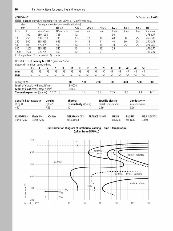
40NiCrMo7 Technical card TrafilixForged quenched and tempered UNI 7874: 1979. Reference only.
size Testing at room temperature (longitudinal) mm R Rp 0.2 A% L A% T A% Q Kv L Kv T Kv Q HB
from to N/mm2 min N/mm2 min min min min J min J min J min for inform.100 930-1080 735 12 30 278-327
100 250 880-1010 735 13 12 10 40 30 25 263-300250 500 835-955 685 14 13 11 40 30 25 250-288500 800 735-885 590 14 12 10 30 25 25 224-265800 1200 685-835 540 13 11 10 25 209-2501200 1550 635-785 490 12 10 9 195-234L = longitudinal T = tangential Q = radial
UNI 7845: 1978 Jominy test HRC grain size 5 min.distance in mm from quenched end
1.5 3 5 7 9 11 13 15 20 25 30 35 40 45 50min 52 52 52 52 52 52 52 52 51 50 49 48 47 45 44max 60 60 60 60 60 60 60 60 59 58 58 58 57 56 56
Testing at °C 20 100 200 300 400 500 600Mod. of elasticity E long. N/mm2 210000Mod. of elasticity G tang. N/mm2 80000Thermal expansion [(m/m·K) ·10–6 °C–1 ] 11.1 12.1 12.9 13.5 13.9 14.1
Specific heat capacity Density Thermal Specific electric ConductivityJ/(kg·K) kg/dm3 conductivity W/(m·K) resist. ohm·mm2/m siemens·m/mm2
460 7.85 42 0.19 5.26
EUROPE EN ITALY UNI CHINA GERMANY DIN FRANCE AFNOR UK BS RUSSIA USA AISI/SAE40NiCrMo7 40NiCrMo7 40NiCrMo8 817M40 40HN2M 4340
750
650
500
400
300
200
Af
MsM50
M90
austenite
austenite +ferrite
austenite + ferrite + carbides
50%
ferrite + carbides
1 10 102 103 104 105 106time [s]
ferrite + carbides
10–1
As
tem
pera
ture
C
Transformation Diagram of isothermal cooling – time – temperature(taken from GERDAU)
96 Part two • Steels for quenching and tempering
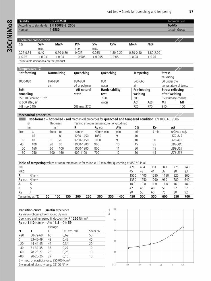
Quality 30CrNiMo8 Technical cardAccording to standards EN 10083-3: 2006 TrafilixNumber 1.6580 Lucefin Group
Chemical compositionC% Si% Mn% P% S% Cr% Mo% Ni%
max max max0.26-0.34 0.40 0.50-0.80 0.025 0.035 1.80-2.20 0.30-0.50 1.80-2.20± 0.02 ± 0.03 ± 0.04 + 0.005 + 0.005 ± 0.05 ± 0.04 ± 0.07Permissible deviations on the product.
Temperature °C Hot forming Normalizing Quenching Quenching Tempering Stress
relieving1050-880 870-880 830-860 850 540-660 50 under the
air oil or polymer water air temperature of temp.Soft +AR natural Hardenability Pre-heating Stress relievingannealing state test welding after welding650-700 cooling 10°/h 850 300 550 furnace coolingto 600 after, air water Ac1 Ac3 Ms Mf(HB max 248) (HB max 370) 720 770 310 100
Table of tempering values at room temperature for round Ø 10 mm after quenching at 850 °C in oilHB 426 404 381 347 275 240HRC 45 43 41 37 28 23R N/mm2 1500 1400 1290 1150 920 800Rp 0.2 N/mm2 1350 1250 1090 960 780 640A % 10.0 10.0 11.0 14.0 16.0 18.0C % 42 45 48 50 52 52Kv J 20 50 60 75 80 92Tempering at °C 50 100 150 200 250 300 350 400 450 500 550 600 650 700
Mechanical propertiesHot-formed – hot-rolled - rod mechanical properties for quenched and tempered condition EN 10083-3: 2006
Ø thickness Testing at room temperature (longitudinal)mm mm R Rp 0.2 A% C% Kv HB
from to from to N/mm2 N/mm2 min min min J min referece only16 8 1250-1450 1050 9 40 370-415
16 40 8 20 1250-1450 1050 9 40 30 370-41540 100 20 60 1000-1300 900 10 45 35 298-380100 160 60 100 1000-1200 800 11 50 45 298-359160 250 100 160 900-1100 700 12 50 45 271-331
Transition-curve Lucefin experienceKv values obtained from round 32 mm Quenched and tempered (induction) for R 1260 N/mm2
Rp 0.2 1110 N/mm2 – A% 11.8 – C% 59average
°C J J Lat. exp. mm Shear %+20 58-72-68 66 0,62 500 53-46-49 49 0,42 40–20 44-44-45 42 0,34 20–40 31-32-35 33 0,27 10–60 28-28-27 28 0,25 10–80 28-26-26 27 0,16 10E = mod. of elasticity long. 255700 N/m2
G = mod. of elastcity tang. 98100 N/m2
Kv Jo
ule
-80 -60 -40 0 +20
100
80
60
40
20
-20
30Cr
NiM
o8Part two • Steels for quenching and tempering 97
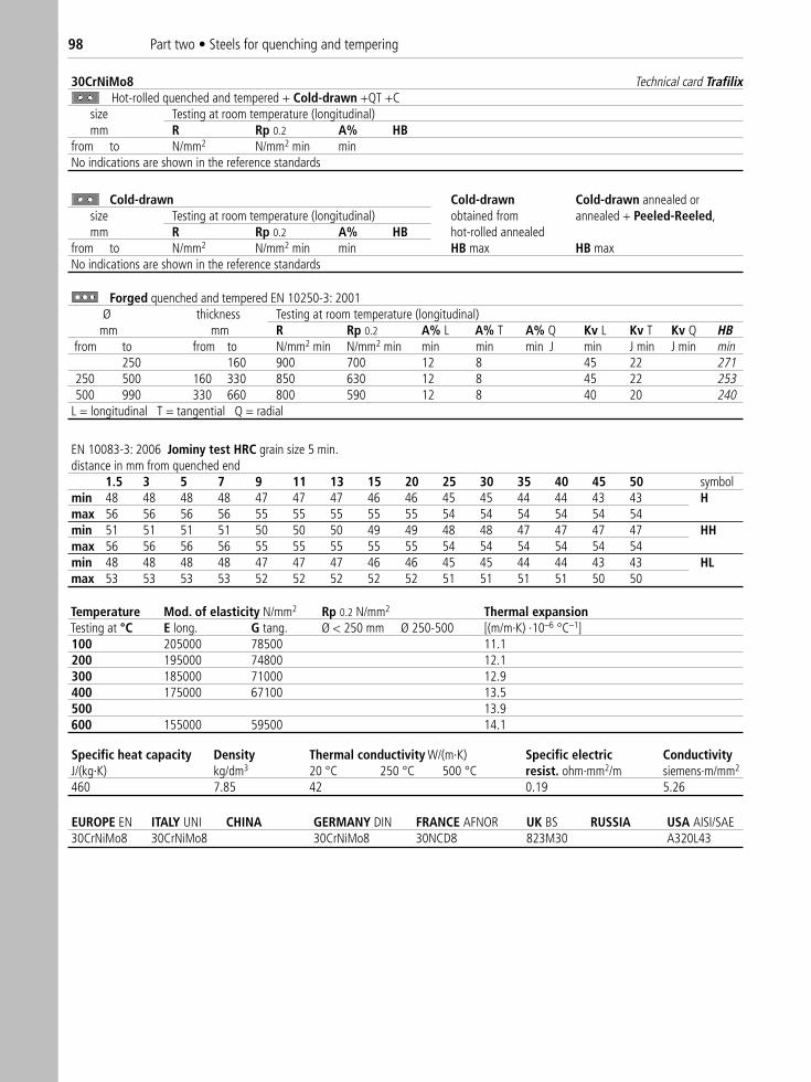
30CrNiMo8 Technical card TrafilixHot-rolled quenched and tempered + Cold-drawn +QT +C
size Testing at room temperature (longitudinal)mm R Rp 0.2 A% HB
from to N/mm2 N/mm2 min minNo indications are shown in the reference standards
Cold-drawn Cold-drawn Cold-drawn annealed orsize Testing at room temperature (longitudinal) obtained from annealed + Peeled-Reeled,mm R Rp 0.2 A% HB hot-rolled annealed
from to N/mm2 N/mm2 min min HB max HB maxNo indications are shown in the reference standards
Temperature Mod. of elasticity N/mm2 Rp 0.2 N/mm2 Thermal expansionTesting at °C E long. G tang. Ø < 250 mm Ø 250-500 [(m/m·K) ·10–6 °C–1]100 205000 78500 11.1200 195000 74800 12.1300 185000 71000 12.9400 175000 67100 13.5500 13.9600 155000 59500 14.1
Specific heat capacity Density Thermal conductivity W/(m·K) Specific electric ConductivityJ/(kg·K) kg/dm3 20 °C 250 °C 500 °C resist. ohm·mm2/m siemens·m/mm2
460 7.85 42 0.19 5.26
EUROPE EN ITALY UNI CHINA GERMANY DIN FRANCE AFNOR UK BS RUSSIA USA AISI/SAE30CrNiMo8 30CrNiMo8 30CrNiMo8 30NCD8 823M30 A320L43
Forged quenched and tempered EN 10250-3: 2001Ø thickness Testing at room temperature (longitudinal)
mm mm R Rp 0.2 A% L A% T A% Q Kv L Kv T Kv Q HBfrom to from to N/mm2 min N/mm2 min min min min J min J min J min min
250 160 900 700 12 8 45 22 271250 500 160 330 850 630 12 8 45 22 253500 990 330 660 800 590 12 8 40 20 240
L = longitudinal T = tangential Q = radial
EN 10083-3: 2006 Jominy test HRC grain size 5 min.distance in mm from quenched end
1.5 3 5 7 9 11 13 15 20 25 30 35 40 45 50 symbolmin 48 48 48 48 47 47 47 46 46 45 45 44 44 43 43 Hmax 56 56 56 56 55 55 55 55 55 54 54 54 54 54 54min 51 51 51 51 50 50 50 49 49 48 48 47 47 47 47 HHmax 56 56 56 56 55 55 55 55 55 54 54 54 54 54 54min 48 48 48 48 47 47 47 46 46 45 45 44 44 43 43 HLmax 53 53 53 53 52 52 52 52 52 51 51 51 51 50 50
98 Part two • Steels for quenching and tempering
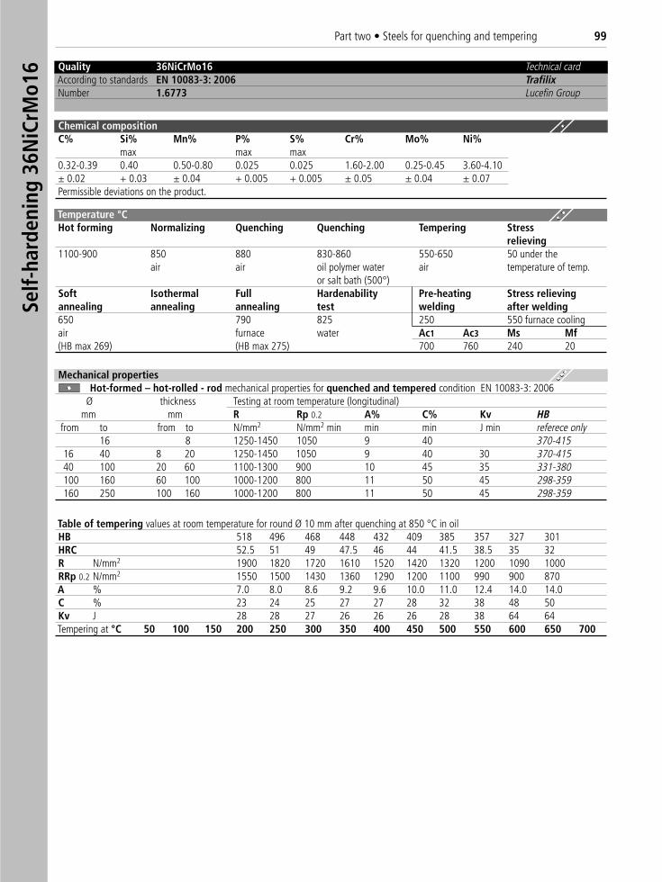
Quality 36NiCrMo16 Technical cardAccording to standards EN 10083-3: 2006 TrafilixNumber 1.6773 Lucefin Group
Chemical compositionC% Si% Mn% P% S% Cr% Mo% Ni%
max max max0.32-0.39 0.40 0.50-0.80 0.025 0.025 1.60-2.00 0.25-0.45 3.60-4.10± 0.02 + 0.03 ± 0.04 + 0.005 + 0.005 ± 0.05 ± 0.04 ± 0.07Permissible deviations on the product.
Table of tempering values at room temperature for round Ø 10 mm after quenching at 850 °C in oilHB 518 496 468 448 432 409 385 357 327 301HRC 52.5 51 49 47.5 46 44 41.5 38.5 35 32R N/mm2 1900 1820 1720 1610 1520 1420 1320 1200 1090 1000RRp 0.2 N/mm2 1550 1500 1430 1360 1290 1200 1100 990 900 870A % 7.0 8.0 8.6 9.2 9.6 10.0 11.0 12.4 14.0 14.0C % 23 24 25 27 27 28 32 38 48 50Kv J 28 28 27 26 26 26 28 38 64 64Tempering at °C 50 100 150 200 250 300 350 400 450 500 550 600 650 700
Mechanical propertiesHot-formed – hot-rolled - rod mechanical properties for quenched and tempered condition EN 10083-3: 2006
Ø thickness Testing at room temperature (longitudinal)mm mm R Rp 0.2 A% C% Kv HB
from to from to N/mm2 N/mm2 min min min J min referece only16 8 1250-1450 1050 9 40 370-415
16 40 8 20 1250-1450 1050 9 40 30 370-41540 100 20 60 1100-1300 900 10 45 35 331-380100 160 60 100 1000-1200 800 11 50 45 298-359160 250 100 160 1000-1200 800 11 50 45 298-359
Temperature °C Hot forming Normalizing Quenching Quenching Tempering Stress
relieving1100-900 850 880 830-860 550-650 50 under the
air air oil polymer water air temperature of temp.or salt bath (500°)
Soft Isothermal Full Hardenability Pre-heating Stress relievingannealing annealing annealing test welding after welding650 790 825 250 550 furnace coolingair furnace water Ac1 Ac3 Ms Mf(HB max 269) (HB max 275) 700 760 240 20
Self-
hard
enin
g 36
NiC
rMo1
6Part two • Steels for quenching and tempering 99
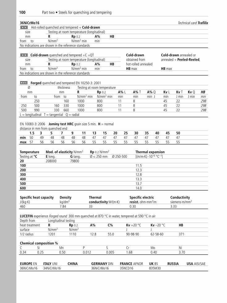
36NiCrMo16 Technical card TrafilixHot-rolled quenched and tempered + Cold-drawn
size Testing at room temperature (longitudinal)mm R Rp 0.2 A% HB
from to N/mm2 N/mm2 min minNo indications are shown in the reference standards
LUCEFIN experience Forged round 300 mm quenched at 870 °C in water, tempered at 590 °C in airDepth from Longitudinal testingheat treatment R Rp 0.2 A% C% Kv +20 °C Kv –20 °C HBsurface N/mm2 N/mm2 J J 1/2 radius 1201 1110 12.8 55.0 90-98-90 62-58-60 371
Chemical composition %C Si Mn P S Cr Mo Ni0.34 0.25 0.50 0.012 0.005 1.68 0.40 3.70
Cold-drawn quenched and tempered +C +QT Cold-drawn Cold-drawn annealed orsize Testing at room temperature (longitudinal) obtained from annealed + Peeled-Reeled,mm R Rp 0.2 A% HB hot-rolled annealed
from to N/mm2 N/mm2 min min HB max HB maxNo indications are shown in the reference standards
EN 10083-3: 2006 Jominy test HRC grain size 5 min. H = normaldistance in mm from quenched end
1.5 3 5 7 9 11 13 15 20 25 30 35 40 45 50min 50 49 48 48 48 48 47 47 47 47 47 47 47 47 47max 57 56 56 56 56 56 55 55 55 55 55 55 55 55 55
Temperature Mod. of elasticity N/mm2 Rp 0.2 N/mm2 Thermal expansionTesting at °C E long. G tang. Ø < 250 mm Ø 250-500 [(m/m·K) ·10–6 °C–1]20 208000 79800100 11.5200 12.3300 12.8400 13.3500 13.7600 14.0
Specific heat capacity Density Thermal Specific electric ConductivityJ/(kg·K) kg/dm3 conductivity W/(m·K) resist. ohm·mm2/m siemens·m/mm2
460 7.84 33 0.30 3.33
EUROPE EN ITALY UNI CHINA GERMANY DIN FRANCE AFNOR UK BS RUSSIA USA AISI/SAE 36NiCrMo16 34NiCrMo16 36NiCrMo16 35NCD16 835M30
Forged quenched and tempered EN 10250-3: 2001Ø thickness Testing at room temperaturemm mm R Rp 0.2 A% L A% T A% Q Kv L Kv T Kv Q HB
from to from to N/mm2 min N/mm2 min min min min J min J min J min min250 160 1000 800 11 8 45 22 298
250 500 160 330 1000 800 11 8 45 22 298500 990 330 660 1000 800 11 8 45 22 298
L = longitudinal T = tangential Q = radial
100 Part two • Steels for quenching and tempering
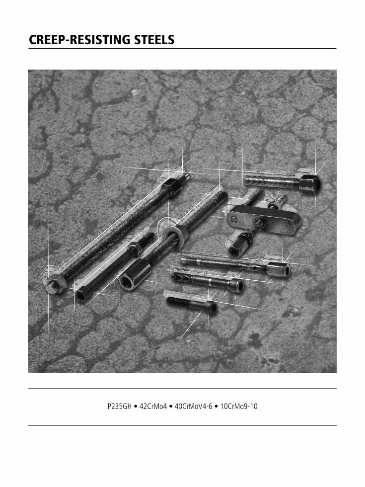
CREEP-RESISTING STEELS
P235GH • 42CrMo4 • 40CrMoV4-6 • 10CrMo9-10
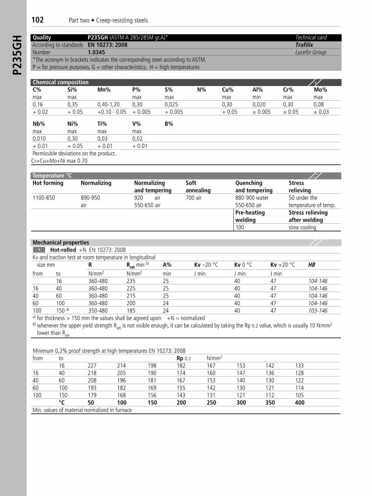
Quality P235GH (ASTM A 285/285M gr.A)*) Technical cardAccording to standards EN 10273: 2008 TrafilixNumber 1.0345 Lucefin Group*The acronym in brackets indicates the corresponding steel according to ASTM.P = for pressure purposes, G = other characteristics; H = high temperatures
Chemical compositionC% Si% Mn% P% S% N% Cu% Al% Cr% Mo%max max max max max min max max0,16 0,35 0,40-1,20 0,30 0,025 0,30 0,020 0,30 0,08+ 0.02 + 0.05 +0.10 - 0.05 + 0.005 + 0.005 + 0.05 ± 0.005 ± 0.05 ± 0.03
Nb% Ni% Ti% V% B%max max max max0,010 0,30 0,03 0,02+ 0.01 + 0.05 + 0.01 + 0.01Permissible deviations on the product.Cr+Cu+Mo+Ni max 0.70
Temperature °C Hot forming Normalizing Normalizing Soft Quenching Stress
and tempering annealing and tempering relieving1100-850 890-950 920 air 700 air 880-900 water 50 under the
air 550-650 air 550-650 air temperature of temp.Pre-heating Stress relievingwelding after welding100 slow cooling
Mechanical propertiesHot-rolled +N EN 10273: 2008
Kv and traction test at room temperature in longitudinalsize mm R ReH min b) A% Kv –20 °C Kv 0 °C Kv +20 °C HB
from to N/mm2 N/mm2 min J min J min J min16 360-480 235 25 40 47 104-146
16 40 360-480 225 25 40 47 104-14640 60 360-480 215 25 40 47 104-14660 100 360-480 200 24 40 47 104-146100 150 a) 350-480 185 24 40 47 103-146a) for thickness > 150 mm the values shall be agreed upon +N = normalized b) whenever the upper yield strength ReH is not visible enough, it can be calculated by taking the Rp 0.2 value, which is usually 10 N/mm2
lower than ReH
Minimum 0,2% proof strength at high temperatures EN 10273: 2008 from to Rp 0.2 N/mm2
16 227 214 198 182 167 153 142 13316 40 218 205 190 174 160 147 136 12840 60 208 196 181 167 153 140 130 12260 100 193 182 169 155 142 130 121 114 100 150 179 168 156 143 131 121 112 105
°C 50 100 150 200 250 300 350 400Min. values of material normalized in furnace
P235
GH
102 Part two • Creep-resisting steels
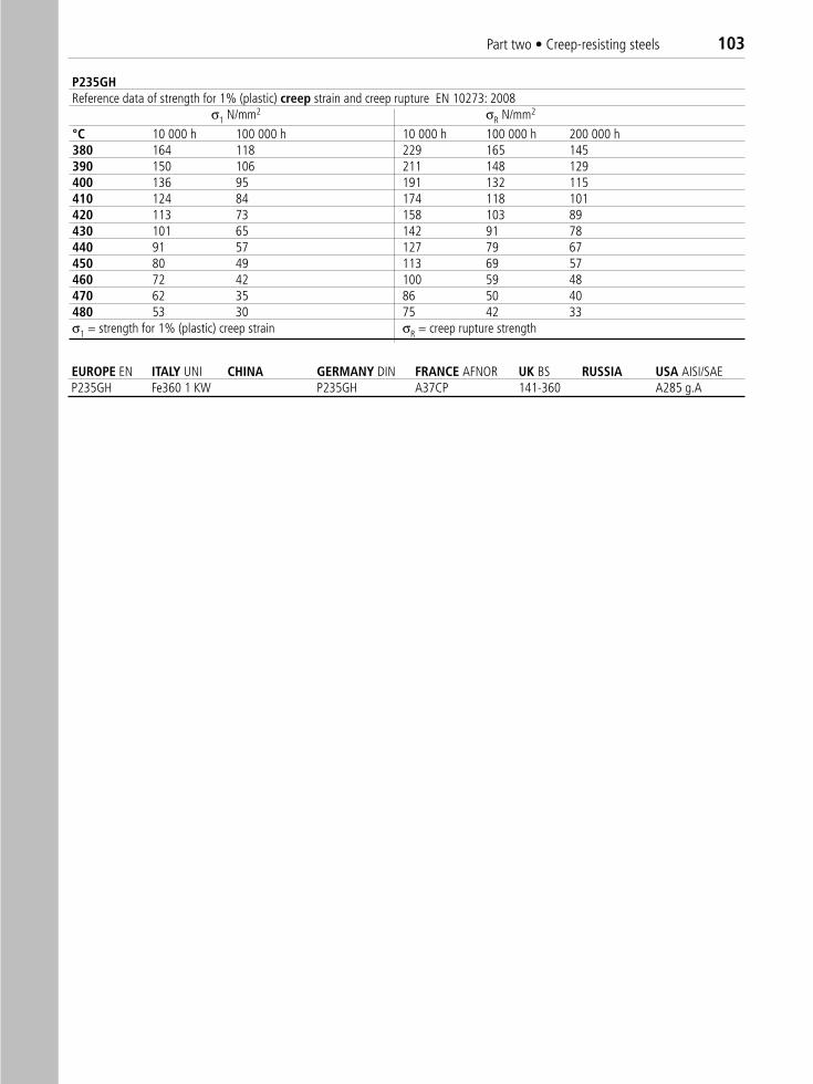
P235GHReference data of strength for 1% (plastic) creep strain and creep rupture EN 10273: 2008
σ1 N/mm2 σR N/mm2
°C 10 000 h 100 000 h 10 000 h 100 000 h 200 000 h380 164 118 229 165 145390 150 106 211 148 129400 136 95 191 132 115410 124 84 174 118 101420 113 73 158 103 89430 101 65 142 91 78440 91 57 127 79 67450 80 49 113 69 57460 72 42 100 59 48470 62 35 86 50 40480 53 30 75 42 33σ1 = strength for 1% (plastic) creep strain σR = creep rupture strength
EUROPE EN ITALY UNI CHINA GERMANY DIN FRANCE AFNOR UK BS RUSSIA USA AISI/SAE P235GH Fe360 1 KW P235GH A37CP 141-360 A285 g.A
Part two • Creep-resisting steels 103
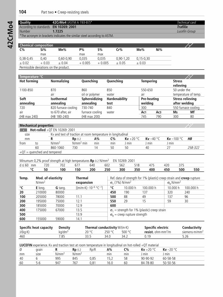
Quality 42CrMo4 (ASTM A 193-B7)*) Technical cardAccording to standards EN 10269: 2001 TrafilixNumber 1.7225 Lucefin Group*The acronym in brackets indicates the similar steel according to ASTM.
Chemical compositionC% Si% Mn% P% S% Cr% Mo% Ni%
max max max0,38-0,45 0,40 0,60-0,90 0,035 0,035 0,90-1,20 0,15-0,30± 0.02 + 0.03 ± 0.04 + 0.005 + 0.005 ± 0.05 ± 0.03Permissible deviations on the product.
Temperature °C Hot forming Normalizing Quenching Quenching Tempering Stress
relieving1100-850 870 860 850 550-650 50 under the
air oil or polymer water air temperature of temp.Soft Isothermal Spheroidizing Hardenability Pre-heating Stress relievingannealing annealing annealing test welding after welding720 820 furnace cooling 730-740 840 300 550 furnace coolingair to 670 after, air furnace cooling water Ac1 Ac3 Ms Mf(HB max 240) (HB 180-240) (HB max 200) 745 790 300 80
Mechanical propertiesHot-rolled +QT EN 10269: 2001
size Kv and test of traction at room temperature in longitudinalmm R Rp 0.2 A% C% Kv +20 °C Kv –40 °C Kv –100 °C HB
from to N/mm2 N/mm2 min min min J min J min J min60 860-1060 730 14 50 50 40 27 258-322
+QT = quenched and tempered
Minumum 0,2% proof strength at high temperatures Rp 0.2 N/mm2 EN 10269: 2001d ≤ 60 mm 720 702 677 640 602 562 518 475 420 375
°C 50 100 150 200 250 300 350 400 450 500 550
Temp. Mod. of elasticity Thermal Ref. data of strength for 1% (plastic) creep strain and creep ruptureN/mm2 exspansion σ1 (1%) N/mm2 σR N/mm2
°C E long. G tang. [(m/m·K) ·10–6 °C–1] °C 10.000 h 100.000 h 10.000 h 100.000 h20 210000 80000 450 190 137 320 240100 205000 78000 11.1 500 88 49 137 96200 195000 75000 12.1 550 29 15 59 30300 185000 70000 12.9 600400 175000 67000 13.5 σ1 = strength for 1% (plastic) creep strain500 13.9 σR = creep rupture strength600 155000 59000 14.1
Specific heat capacity Density Thermal conductivity W/(m·K) Specific electric ConductivityJ/(kg·K) kg/dm3 20 °C 250 °C 500 °C resist. ohm·mm2/m siemens·m/mm2
460 7.85 33.5 34.0 34.2 0.19 5.26
LUCEFIN experience. Kv and traction test at room temperature in longitudinal on hot-rolled +QT materialØ grain R Rp 0.2 Rp/R A% C% Kv +20 °C Kv –20 °Cmm size N/mm2 N/mm2 min min J min J min40 6 995 845 0,85 15,2 58 90-90-92 60-58-5860 5-6 947 767 0,81 16.0 60 84-78-80 50-50-56
42Cr
Mo4
104 Part two • Creep-resisting steels
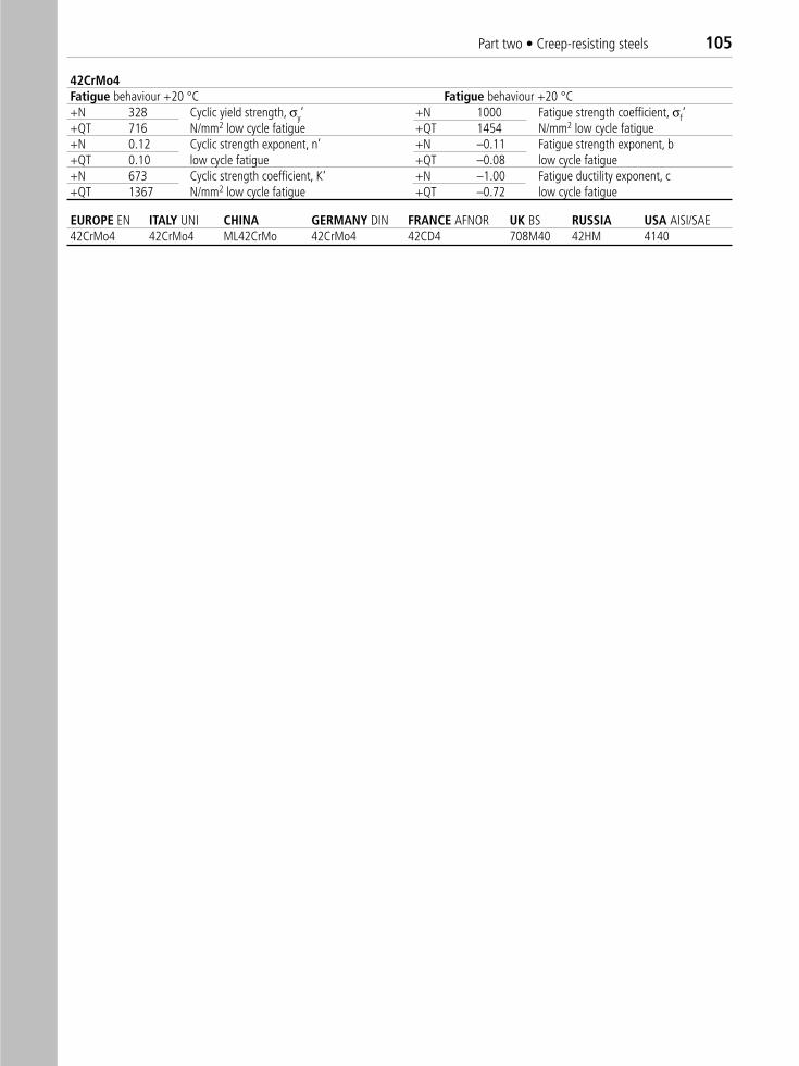
42CrMo4Fatigue behaviour +20 °C Fatigue behaviour +20 °C+N 328 Cyclic yield strength, σy’ +N 1000 Fatigue strength coefficient, σf‘+QT 716 N/mm2 low cycle fatigue +QT 1454 N/mm2 low cycle fatigue+N 0.12 Cyclic strength exponent, n’ +N –0.11 Fatigue strength exponent, b+QT 0.10 low cycle fatigue +QT –0.08 low cycle fatigue+N 673 Cyclic strength coefficient, K‘ +N –1.00 Fatigue ductility exponent, c +QT 1367 N/mm2 low cycle fatigue +QT –0.72 low cycle fatigue
EUROPE EN ITALY UNI CHINA GERMANY DIN FRANCE AFNOR UK BS RUSSIA USA AISI/SAE 42CrMo4 42CrMo4 ML42CrMo 42CrMo4 42CD4 708M40 42HM 4140
Part two • Creep-resisting steels 105
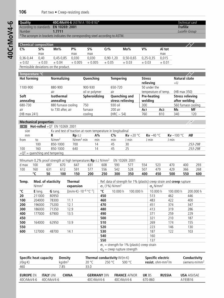
106 Part two • Creep-resisting steels40
CrM
oV4-
6
EUROPE EN ITALY UNI CHINA GERMANY DIN FRANCE AFNOR UK BS RUSSIA USA AISI/SAE40CrMoV4-6 40CrMoV4-6 40CrMoV4-6 40CrMoV4-6 670-860 A193B16
Quality 40CrMoV4-6 (ASTM A 193-B16)* Technical cardAccording to standards EN 10269: 2001 TrafilixNumber 1.7711 Lucefin Group*The acronym in brackets indicates the corresponding steel according to ASTM.
Chemical compositionC% Si% Mn% P% S% Cr% Mo% V% Al tot
max max max max0,36-0,44 0,40 0,45-0,85 0,030 0,030 0,90-1,20 0,50-0,65 0,25-0,35 0,015± 0.02 ± 0.03 ± 0.04 + 0.005 + 0.005 ± 0.05 ± 0.03 ± 0.03 ± 0.01Permissible deviations on the product.
Temperature °CHot forming Normalizing Quenching Tempering Stress Natural state
relieving +U1100-900 880-900 900-930 650-720 50 under the
air oil or polymer air temperature of temp. (HB max 350)Soft Isothermal Spheroidizing Quenching and Pre-heating Stress relievingannealing annealing stress relieving welding after welding680-730 880 furnace cooling 750 930 oil 300 560 furnace coolingair to 730 after, air furnace 200 air Ac1 Ac3 Ms Mf(HB max 241) cooling (HRC ~ 54) 760 810 340 120
Mechanical propertiesHot-rolled +QT EN 10269: 2001
size Kv and test of traction at room temperature in longitudinalmm R Rp 0.2 A% C% Kv +20 °C Kv –40 °C Kv –100 °C HB
from to N/mm2 N/mm2 min min min J min J min J min100 850-1000 700 14 45 30 253-298
100 160 850-1000 640 14 45 25 253-298+QT = quenching and tempering
Minumum 0,2% proof strength at high temperatures Rp 0.2 N/mm2 EN 10269: 2001d max 100 687 670 647 631 608 593 577 554 523 470 400 293100 160 631 612 591 577 556 542 528 507 479 429 366 268
°C 50 100 150 200 250 300 350 400 450 500 550 600
Temp. Mod. of elasticity Thermal Ref. data of strength for 1% (plastic) creep strain and creep ruptureN/mm2 expansion σ1 (1%) N/mm2 σR N/mm2
°C E long. G tang. [(m/m·K) ·10–6 °C–1] °C 10.000 h 100.000 h 10.000 h 100.000 h 200.000 h20 211000 80950 450 513 462 446100 204000 78300 11.1 460 483 422 400200 196000 75200 12.1 470 451 374 347300 186000 71350 12.9 480 413 319 286400 177000 67900 13.5 490 371 259 229450 500 321 210 187500 164000 62950 13.9 510 269 174 155550 520 223 146 130600 127000 48700 14.1 530 187 122 103
540 160550 137σ1 = strength for 1% (plastic) creep strainσR = creep rupture strength
Specific heat capacity Density Thermal conductivity W/(m·K) Specific electric ConductivityJ/(kg·K) kg/dm3 20 °C 250 °C 500 °C resist. ohm·mm2/m siemens·m/mm2
460 7.85 33.0
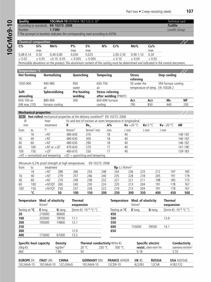
Quality 10CrMo9-10 (ASTM A 182 F22 cl. 3)*) Technical cardAccording to standards EN 10273: 2008 TrafilixNumber 1.7380 Lucefin Group* The acronym in brackets indicates the corresponding steel according to ASTM.
Chemical compositionC% Si% Mn% P% S% N% Cr% Mo% Cu%
max max max max0,08-0,14 0,50 0,40-0,80 0,030 0,025 2,00-2,50 0,90-1,10 0,30+ 0.02 ± 0.05 +0.10 -0.05 + 0.005 + 0.005 ± 0.10 ± 0.04 + 0.05Permissible deviations on the product. The aluminium content of the casting must be determined and indicated in the control document.
Temperature °C Hot forming Normalizing Quenching Tempering Stress Step cooling
relieving1050-900 940-980 950 650-750 50 under the 593 furnace cooling
air water air temperature of temp. EN 10028-2Soft Spheroidizing Pre-heating Stress relievingannealing welding after welding (PWHT)650-700 air 880-900 300 600-690 furnace Ac1 Ac3 Ms Mf(HB max 210) furnace cooling cooling 795 850 440 230
Mechanical propertiesHot-rolled mechanical properties at the delivery conditionb) EN 10273: 2008
Ø heat Kv and test of traction at room temperature in longitudinalmm treatment R ReH A% Kv +20 °C Kv 0 °C Kv –20 °C HB
from to b) N/mm2 N/mm2 min min J min J min J min16 +NT 480-630 310 18 40 146-192
16 40 +NT 480-630 300 18 40 146-19240 60 +NT 480-630 290 18 40 146-19260 100 +NT or +QT 470-620 270 17 40 141-190100 150 +QT 460-610 250 17 40 139-183+NT = normalized and tempering +QT = quenching and tempering
Minumum 0,2% proof strength at high temperatures EN 10273: 2008from to treatment Rp 0.2 N/mm2
16 +NT 288 266 254 248 243 236 225 212 197 18516 40 +NT 279 257 246 240 235 228 218 205 191 17940 60 +NT 270 249 238 232 227 221 211 198 185 17360 100 +NT/QT 260 240 230 224 220 213 204 191 178 167100 150 +NT/QT 250 237 228 222 219 213 204 191 178 167
°C 50 100 150 200 250 300 350 400 450 500
Temperature Mod. of elasticity ThermalN/mm2 exspansion
Testing at °C E long. G tang. [(m/m·K) ·10–6 °C–1]20 210000 80600100 205000 78700 11.1200 195000 74800 12.1250300 12.9400 175000 67000 13.5
Temperature Mod. of elasticity Thermal N/mm2 exspansion
Testing at °C E long. G tang. [(m/m·K) ·10–6 °C–1]450500 13.9550600 155000 59500 14.1650
EUROPE EN ITALY UNI CHINA GERMANY DIN FRANCE AFNOR UK BS RUSSIA USA AISI/SAE 10CrMo9-10 10CrMo9-10 12Cr2MoG 10CrMo9-10 12CD9-10 622/B3 12Ch8 A182 F22
Specific heat capacity Density Thermal conductivity W/(m·K) Specific electric ConductivityJ/(kg·K) kg/dm3 20 °C 250 °C 500 °C resist. ohm·mm2/m siemens·m/mm2
460 7.80 50 0.18 5.55
Part two • Creep-resisting steels 10710
CrM
o9-1
0
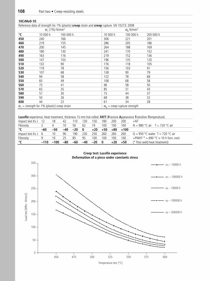
10CrMo9-10 Reference data of strength for 1% (plastic) creep strain and creep rupture EN 10273: 2008
σ1 (1%) N/mm2 σR N/mm2
°C 10 000 h 100 000 h 10 000 h 100 000 h 200 000 h450 240 166 306 221 201460 219 155 286 205 186470 200 145 264 188 169480 180 130 241 170 152490 163 116 219 152 136500 147 103 196 135 120510 132 90 176 118 105520 119 78 156 103 91530 107 68 138 90 79540 94 58 122 78 68550 83 49 108 68 58560 73 41 96 58 50570 65 35 85 51 43580 57 30 75 44 37590 50 26 68 38 32600 44 22 61 34 28σ1 = strength for 1% (plastic) creep strain σR = creep rupture strength
350
300
250
200
150
100
50
0450 475 500 525 550 575 600
Temperature test [°C]
Load
test
[MPa
- N
/mm
2]
σ1 – 10000 h
σ1 – 100000 h
σr – 10000 h
σr – 100000 h
σr – 200000 h
Creep test
Creep test: Lucefin experienceDeformation of a piece under constants stress
Lucefin experience. Heat treatment, thickness 15 mm hot-rolled. FATT (Fracture Appearance Transition Temperature)Impact test Kv J 12 18 42 110 130 150 180 200 200 +NT Fibrosity 2 4 10 50 62 74 100 100 100 N = 980 °C air T = 720 °C air°C –60 –50 –40 –20 0 +20 +50 +80 +100Impact test Kv J 6 10 90 190 230 250 260 260 260 Q = 950 °C water T = 720 °C airFibrosity 9 10 25 85 95 100 100 100 100 +PWHT * = 690 °C × 10 h furn. cool.°C –110 –100 –80 –60 –40 –20 0 +20 +50 (* Post weld heat treatment)
108 Part two • Creep-resisting steels
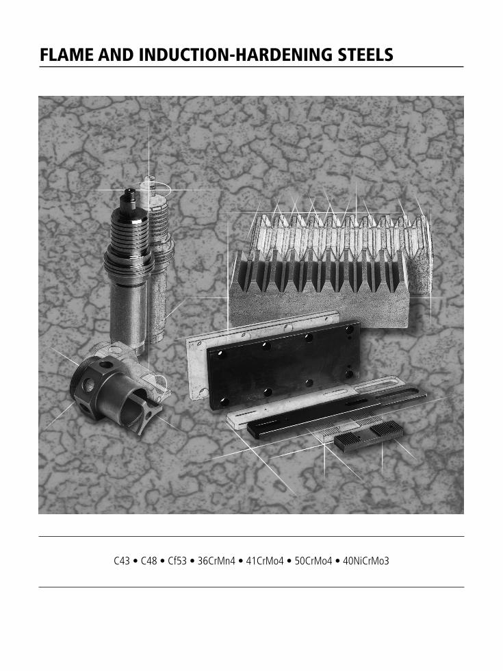
FLAME AND INDUCTION-HARDENING STEELS
C43 • C48 • Cf53 • 36CrMn4 • 41CrMo4 • 50CrMo4 • 40NiCrMo3
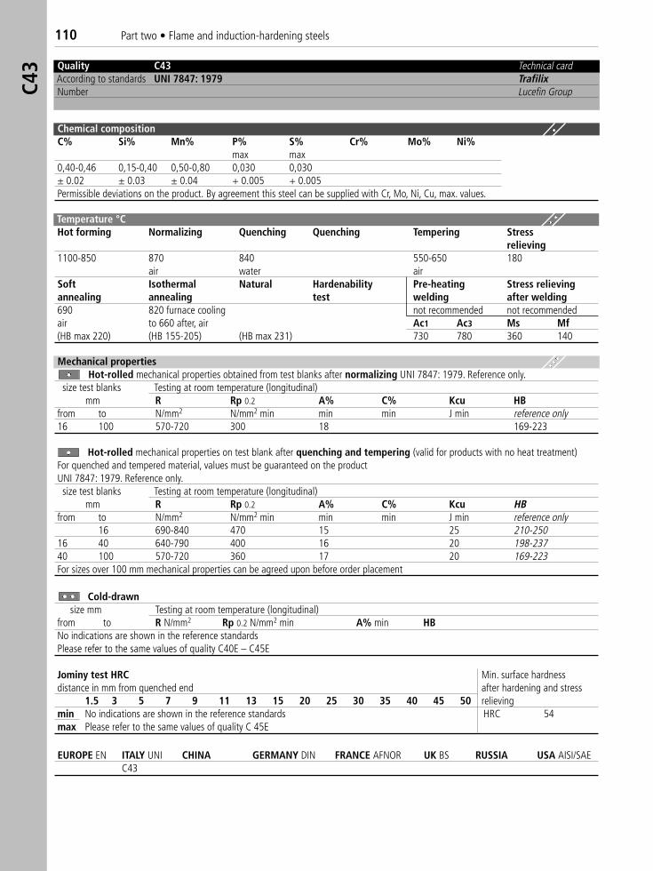
110 Part two • Flame and induction-hardening steelsC4
3 Quality C43 Technical cardAccording to standards UNI 7847: 1979 TrafilixNumber Lucefin Group
Chemical compositionC% Si% Mn% P% S% Cr% Mo% Ni%
max max0,40-0,46 0,15-0,40 0,50-0,80 0,030 0,030± 0.02 ± 0.03 ± 0.04 + 0.005 + 0.005Permissible deviations on the product. By agreement this steel can be supplied with Cr, Mo, Ni, Cu, max. values.
Temperature °C Hot forming Normalizing Quenching Quenching Tempering Stress
relieving1100-850 870 840 550-650 180
air water airSoft Isothermal Natural Hardenability Pre-heating Stress relievingannealing annealing test welding after welding690 820 furnace cooling not recommended not recommendedair to 660 after, air Ac1 Ac3 Ms Mf(HB max 220) (HB 155-205) (HB max 231) 730 780 360 140
Mechanical propertiesHot-rolled mechanical properties obtained from test blanks after normalizing UNI 7847: 1979. Reference only.
size test blanks Testing at room temperature (longitudinal) mm R Rp 0.2 A% C% Kcu HB
from to N/mm2 N/mm2 min min min J min reference only16 100 570-720 300 18 169-223
Hot-rolled mechanical properties on test blank after quenching and tempering (valid for products with no heat treatment)For quenched and tempered material, values must be guaranteed on the productUNI 7847: 1979. Reference only.size test blanks Testing at room temperature (longitudinal)
mm R Rp 0.2 A% C% Kcu HBfrom to N/mm2 N/mm2 min min min J min reference only
16 690-840 470 15 25 210-25016 40 640-790 400 16 20 198-23740 100 570-720 360 17 20 169-223For sizes over 100 mm mechanical properties can be agreed upon before order placement
Cold-drawnsize mm Testing at room temperature (longitudinal)
from to R N/mm2 Rp 0.2 N/mm2 min A% min HB No indications are shown in the reference standardsPlease refer to the same values of quality C40E – C45E
Jominy test HRC Min. surface hardness distance in mm from quenched end after hardening and stress
1.5 3 5 7 9 11 13 15 20 25 30 35 40 45 50 relievingmin No indications are shown in the reference standards HRC 54max Please refer to the same values of quality C 45E
EUROPE EN ITALY UNI CHINA GERMANY DIN FRANCE AFNOR UK BS RUSSIA USA AISI/SAE C43
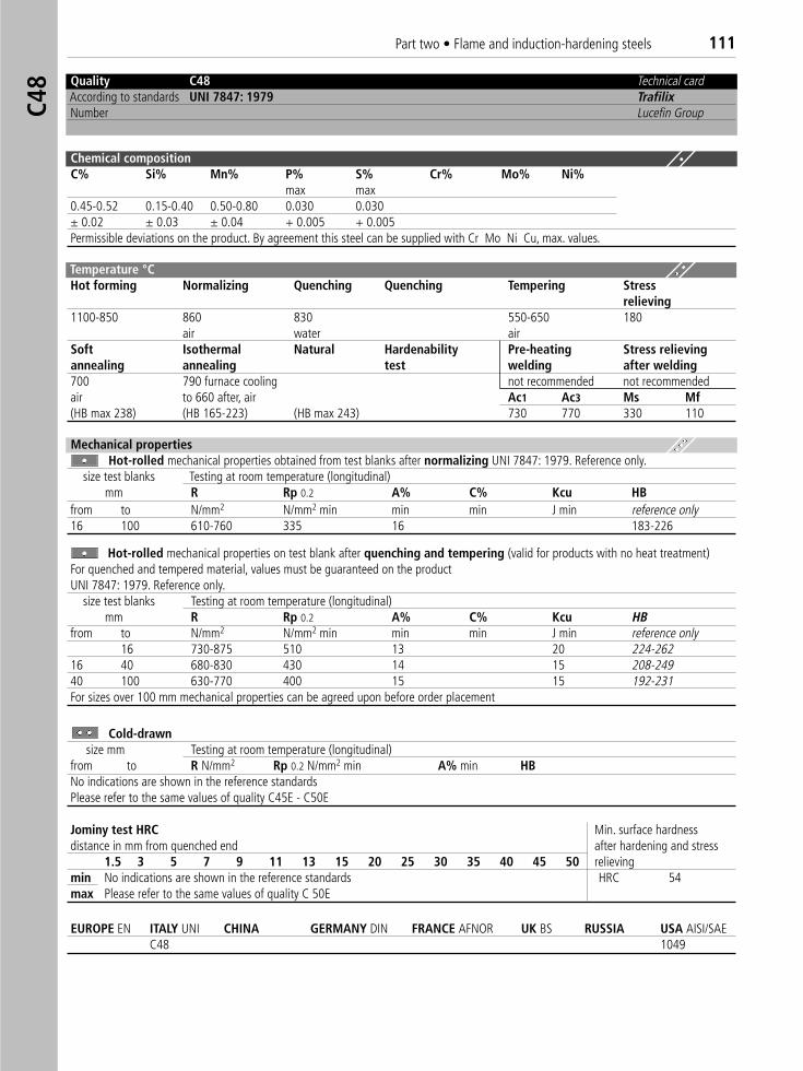
Part two • Flame and induction-hardening steels 111C4
8
Chemical compositionC% Si% Mn% P% S% Cr% Mo% Ni%
max max0.45-0.52 0.15-0.40 0.50-0.80 0.030 0.030± 0.02 ± 0.03 ± 0.04 + 0.005 + 0.005Permissible deviations on the product. By agreement this steel can be supplied with Cr Mo Ni Cu, max. values.
Temperature °C Hot forming Normalizing Quenching Quenching Tempering Stress
relieving1100-850 860 830 550-650 180
air water airSoft Isothermal Natural Hardenability Pre-heating Stress relievingannealing annealing test welding after welding700 790 furnace cooling not recommended not recommendedair to 660 after, air Ac1 Ac3 Ms Mf(HB max 238) (HB 165-223) (HB max 243) 730 770 330 110
Mechanical propertiesHot-rolled mechanical properties obtained from test blanks after normalizing UNI 7847: 1979. Reference only.
size test blanks Testing at room temperature (longitudinal) mm R Rp 0.2 A% C% Kcu HB
from to N/mm2 N/mm2 min min min J min reference only16 100 610-760 335 16 183-226
Hot-rolled mechanical properties on test blank after quenching and tempering (valid for products with no heat treatment)For quenched and tempered material, values must be guaranteed on the productUNI 7847: 1979. Reference only.
size test blanks Testing at room temperature (longitudinal)mm R Rp 0.2 A% C% Kcu HB
from to N/mm2 N/mm2 min min min J min reference only16 730-875 510 13 20 224-262
16 40 680-830 430 14 15 208-24940 100 630-770 400 15 15 192-231For sizes over 100 mm mechanical properties can be agreed upon before order placement
Cold-drawnsize mm Testing at room temperature (longitudinal)
from to R N/mm2 Rp 0.2 N/mm2 min A% min HBNo indications are shown in the reference standardsPlease refer to the same values of quality C45E - C50E
Jominy test HRC Min. surface hardnessdistance in mm from quenched end after hardening and stress
1.5 3 5 7 9 11 13 15 20 25 30 35 40 45 50 relievingmin No indications are shown in the reference standards HRC 54max Please refer to the same values of quality C 50E
EUROPE EN ITALY UNI CHINA GERMANY DIN FRANCE AFNOR UK BS RUSSIA USA AISI/SAEC48 1049
Quality C48 Technical cardAccording to standards UNI 7847: 1979 TrafilixNumber Lucefin Group
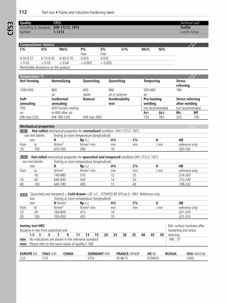
112 Part two • Flame and induction-hardening steelsCf
53
Quality Cf53 Technical cardAccording to standards DIN 17212: 1972 TrafilixNumber 1.1213 Lucefin Group
Composizione chimicaC% Si% Mn% P% S% Cr% Mo% Ni%
max max0.50-0.57 0.15-0.35 0.40-0.70 0.025 0.035± 0.03 ± 0.03 ± 0.04 + 0.005 + 0.005Permissible deviations on the product.
Temperature °C Hot forming Normalizing Quenching Quenching Tempering Stress
relieving1050-850 860 830 860 550-660 180
air water oil or polymer airSoft Isothermal Natural Hardenability Pre-heating Stress relievingannealing annealing test welding after welding700 820 furnace cooling not recommended not recommendedair to 660 after, air Ac1 Ac3 Ms Mf(HB max 223) (HB 180-230) (HB max 260) 730 765 320 100
Mechanical propertiesHot-rolled mechanical properties for normalized condition DIN 17212: 1972
size test blanks Testing at room temperature (longitudinal)mm R Rp 0.2 A% C% K HB
from to N/mm2 N/mm2 min min min J min reference only16 100 610-760 340 16 183-226
Hot-rolled mechanical properties for quenched and tempered condition DIN 17212: 1972size test blanks Testing at room temperature (longitudinal)
mm R Rp 0.2 A% C% K HBfrom to N/mm2 N/mm2 min min min J min reference only
16 740-880 510 12 25 224-26316 40 690-830 430 14 35 210-24940 100 640-780 400 15 40 198-232
Quenched and tempered + Cold-drawn +QT +C 070M55 BS 970 pt.3: 1991. Reference only.size Testing at room temperature (longitudinal) mm R N/mm2 Rp 0.2 A% C% K HB
from to N/mm2 N/mm2 min min min J min reference only13 29 700-850 475 10 201-25529 100 700-850 435 10 201-255
Jominy test HRC Min. surface hardness afterdistance in mm from quenched end hardening and stress
1.5 3 5 7 9 11 13 15 20 25 30 35 40 45 50 relievingmin No indications are shown in the reference standard HRC 57max Please refer to the same values of quality C 50E
EUROPE EN ITALY UNI CHINA GERMANY DIN FRANCE AFNOR UK BS RUSSIA USA AISI/SAE C53 C53 Cf53 XC48 TS 070M55 1050
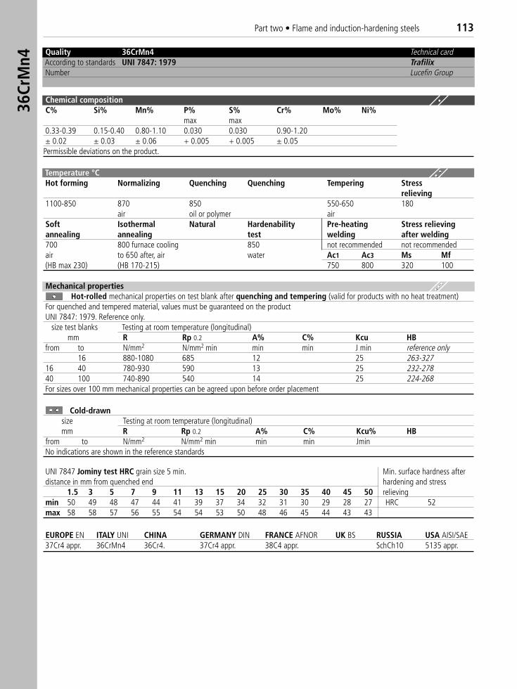
Part two • Flame and induction-hardening steels 11336
CrM
n4
Quality 36CrMn4 Technical cardAccording to standards UNI 7847: 1979 TrafilixNumber Lucefin Group
Chemical compositionC% Si% Mn% P% S% Cr% Mo% Ni%
max max0.33-0.39 0.15-0.40 0.80-1.10 0.030 0.030 0.90-1.20± 0.02 ± 0.03 ± 0.06 + 0.005 + 0.005 ± 0.05Permissible deviations on the product.
Temperature °C Hot forming Normalizing Quenching Quenching Tempering Stress
relieving1100-850 870 850 550-650 180
air oil or polymer airSoft Isothermal Natural Hardenability Pre-heating Stress relievingannealing annealing test welding after welding700 800 furnace cooling 850 not recommended not recommendedair to 650 after, air water Ac1 Ac3 Ms Mf(HB max 230) (HB 170-215) 750 800 320 100
Mechanical propertiesHot-rolled mechanical properties on test blank after quenching and tempering (valid for products with no heat treatment)
For quenched and tempered material, values must be guaranteed on the productUNI 7847: 1979. Reference only. �
size test blanks Testing at room temperature (longitudinal) mm R Rp 0.2 A% C% Kcu HB
from to N/mm2 N/mm2 min min min J min reference only16 880-1080 685 12 25 263-327
16 40 780-930 590 13 25 232-27840 100 740-890 540 14 25 224-268For sizes over 100 mm mechanical properties can be agreed upon before order placement
Cold-drawnsize Testing at room temperature (longitudinal) mm R Rp 0.2 A% C% Kcu% HB
from to N/mm2 N/mm2 min min min JminNo indications are shown in the reference standards
UNI 7847 Jominy test HRC grain size 5 min. Min. surface hardness afterdistance in mm from quenched end hardening and stress
1.5 3 5 7 9 11 13 15 20 25 30 35 40 45 50 relievingmin 50 49 48 47 44 41 39 37 34 32 31 30 29 28 27 HRC 52max 58 58 57 56 55 54 54 53 50 48 46 45 44 43 43
EUROPE EN ITALY UNI CHINA GERMANY DIN FRANCE AFNOR UK BS RUSSIA USA AISI/SAE 37Cr4 appr. 36CrMn4 36Cr4. 37Cr4 appr. 38C4 appr. SchCh10 5135 appr.
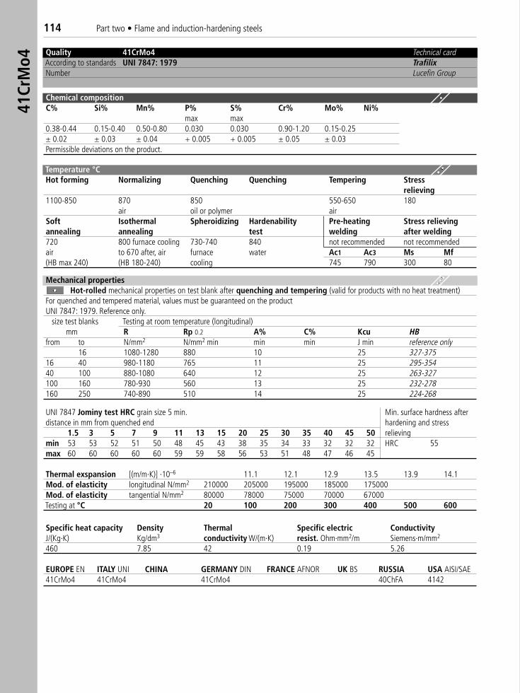
114 Part two • Flame and induction-hardening steels41
CrM
o4
Quality 41CrMo4 Technical cardAccording to standards UNI 7847: 1979 TrafilixNumber Lucefin Group
Chemical compositionC% Si% Mn% P% S% Cr% Mo% Ni%
max max0.38-0.44 0.15-0.40 0.50-0.80 0.030 0.030 0.90-1.20 0.15-0.25± 0.02 ± 0.03 ± 0.04 + 0.005 + 0.005 ± 0.05 ± 0.03Permissible deviations on the product.
Temperature °C Hot forming Normalizing Quenching Quenching Tempering Stress
relieving1100-850 870 850 550-650 180
air oil or polymer airSoft Isothermal Spheroidizing Hardenability Pre-heating Stress relievingannealing annealing test welding after welding720 800 furnace cooling 730-740 840 not recommended not recommendedair to 670 after, air furnace water Ac1 Ac3 Ms Mf(HB max 240) (HB 180-240) cooling 745 790 300 80
Mechanical propertiesHot-rolled mechanical properties on test blank after quenching and tempering (valid for products with no heat treatment)
For quenched and tempered material, values must be guaranteed on the productUNI 7847: 1979. Reference only.
size test blanks Testing at room temperature (longitudinal) mm R Rp 0.2 A% C% Kcu HB
from to N/mm2 N/mm2 min min min J min reference only16 1080-1280 880 10 25 327-375
16 40 980-1180 765 11 25 295-35440 100 880-1080 640 12 25 263-327100 160 780-930 560 13 25 232-278160 250 740-890 510 14 25 224-268
UNI 7847 Jominy test HRC grain size 5 min. Min. surface hardness afterdistance in mm from quenched end hardening and stress
1.5 3 5 7 9 11 13 15 20 25 30 35 40 45 50 relievingmin 53 53 52 51 50 48 45 43 38 35 34 33 32 32 32 HRC 55max 60 60 60 60 60 59 59 58 56 53 51 48 47 46 45
Thermal exspansion [(m/m·K)] ·10–6 11.1 12.1 12.9 13.5 13.9 14.1Mod. of elasticity longitudinal N/mm2 210000 205000 195000 185000 175000Mod. of elasticity tangential N/mm2 80000 78000 75000 70000 67000Testing at °C 20 100 200 300 400 500 600
Specific heat capacity Density Thermal Specific electric ConductivityJ/(Kg·K) Kg/dm3 conductivity W/(m·K) resist. Ohm·mm2/m Siemens·m/mm2
460 7.85 42 0.19 5.26
EUROPE EN ITALY UNI CHINA GERMANY DIN FRANCE AFNOR UK BS RUSSIA USA AISI/SAE 41CrMo4 41CrMo4 41CrMo4 40ChFA 4142
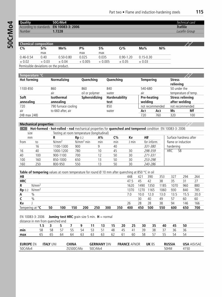
Part two • Flame and induction-hardening steels 11550
CrM
o4
Quality 50CrMo4 Technical cardAccording to standards EN 10083-3: 2006 TrafilixNumber 1.7228 Lucefin Group
Chemical compositionC% Si% Mn% P% S% Cr% Mo% Ni%
max max max0.46-0.54 0.40 0.50-0.80 0.025 0.035 0.90-1.20 0.15-0.30± 0.02 + 0.03 ± 0.04 + 0.005 + 0.005 ± 0.05 ± 0.03Permissible deviations on the product.
Temperature °C Hot forming Normalizing Quenching Quenching Tempering Stress
relieving1100-850 860 860 840 540-680 50 under the
air oil or polymer water air temperature of temp.Soft Isothermal Spheroidizing Hardenability Pre-heating Stress relievingannealing annealing test welding after welding720 790 furnace cooling 850 not recommended not recommendedair to 660 after, air water Ac1 Ac3 Ms Mf(HB max 248) 720 760 320 100
Mechanical propertiesHot-formed - hot-rolled - rod mechanical properties for quenched and tempered condition EN 10083-3: 2006
size Testing at room temperature (longitudinal)mm R Rp 0.2 A% C% Kv HB Surface hardness after
from to N/mm2 N/mm2 min min min J min for inform. flame or induction16 1100-1300 900 9 40 331-380 hardening
16 40 1000-1200 780 10 45 30 298-359 HRC 5840 100 900-1100 700 12 50 30 271-331100 160 850-1000 650 13 50 30 253-298160 250 800-950 550 13 50 30 240-286
Table of tempering values at room temperature for round Ø 10 mm after quenching at 850 °C in oilHB 448 421 390 353 327 294 264HRC 47.5 45 42 38 35 31 27R N/mm2 1620 1490 1350 1185 1070 960 880Rp 0.2 N/mm2 1370 1270 1165 1060 930 840 785A % 7.0 10.0 12.0 13.0 13.5 15.5 20.0C % 30 40 49 57 60 60Kv J 26 28 28 38 94 146 166Tempering at °C 50 100 150 200 250 300 350 400 450 500 550 600 650 700
EN 10083-3: 2006 Jominy test HRC grain size 5 min. H = normaldistance in mm from quenched end
1.5 3 5 7 9 11 13 15 20 25 30 35 40 45 50min 58 58 57 55 54 53 51 48 45 41 39 38 37 36 36max 65 65 64 64 63 63 63 62 61 60 58 57 55 54 54
EUROPE EN ITALY UNI CHINA GERMANY DIN FRANCE AFNOR UK BS RUSSIA USA AISI/SAE50CrMo4 ZG500CrMo 50CrMo4 50HM 4150
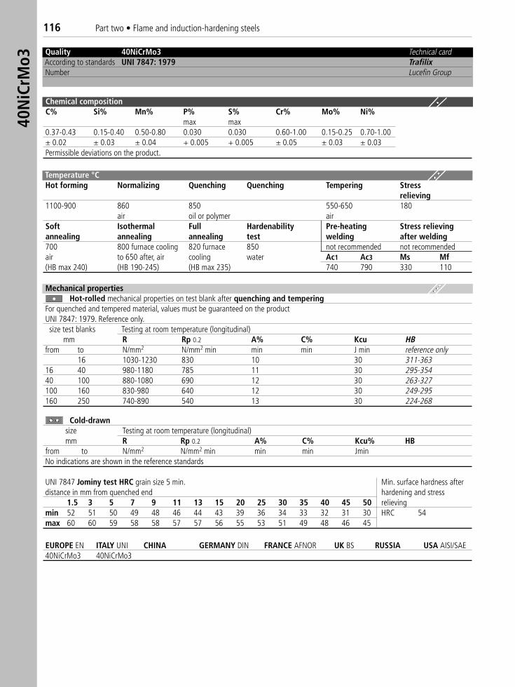
116 Part two • Flame and induction-hardening steels40
NiC
rMo3
Quality 40NiCrMo3 Technical cardAccording to standards UNI 7847: 1979 TrafilixNumber Lucefin Group
Chemical compositionC% Si% Mn% P% S% Cr% Mo% Ni%
max max0.37-0.43 0.15-0.40 0.50-0.80 0.030 0.030 0.60-1.00 0.15-0.25 0.70-1.00± 0.02 ± 0.03 ± 0.04 + 0.005 + 0.005 ± 0.05 ± 0.03 ± 0.03Permissible deviations on the product.
Temperature °C Hot forming Normalizing Quenching Quenching Tempering Stress
relieving1100-900 860 850 550-650 180
air oil or polymer airSoft Isothermal Full Hardenability Pre-heating Stress relievingannealing annealing annealing test welding after welding700 800 furnace cooling 820 furnace 850 not recommended not recommendedair to 650 after, air cooling water Ac1 Ac3 Ms Mf(HB max 240) (HB 190-245) (HB max 235) 740 790 330 110
Mechanical propertiesHot-rolled mechanical properties on test blank after quenching and tempering
For quenched and tempered material, values must be guaranteed on the productUNI 7847: 1979. Reference only.size test blanks Testing at room temperature (longitudinal)
mm R Rp 0.2 A% C% Kcu HBfrom to N/mm2 N/mm2 min min min J min reference only
16 1030-1230 830 10 30 311-36316 40 980-1180 785 11 30 295-35440 100 880-1080 690 12 30 263-327100 160 830-980 640 12 30 249-295160 250 740-890 540 13 30 224-268
Cold-drawnsize Testing at room temperature (longitudinal) mm R Rp 0.2 A% C% Kcu% HB
from to N/mm2 N/mm2 min min min JminNo indications are shown in the reference standards
UNI 7847 Jominy test HRC grain size 5 min. Min. surface hardness afterdistance in mm from quenched end hardening and stress
1.5 3 5 7 9 11 13 15 20 25 30 35 40 45 50 relievingmin 52 51 50 49 48 46 44 43 39 36 34 33 32 31 30 HRC 54max 60 60 59 58 58 57 57 56 55 53 51 49 48 46 45
EUROPE EN ITALY UNI CHINA GERMANY DIN FRANCE AFNOR UK BS RUSSIA USA AISI/SAE40NiCrMo3 40NiCrMo3
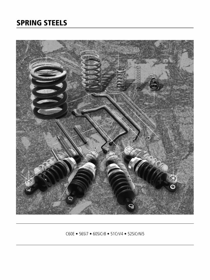
SPRING STEELS
C60E • 56Si7 • 60SiCr8 • 51CrV4 • 52SiCrNi5
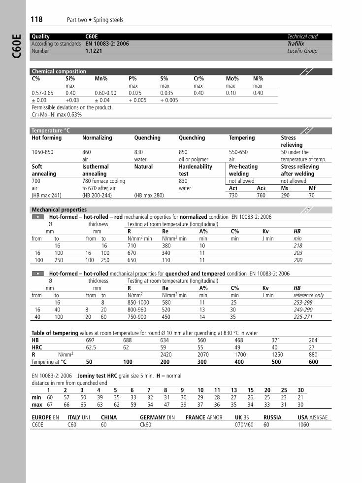
118 Part two • Spring steelsC6
0E
Quality C60E Technical cardAccording to standards EN 10083-2: 2006 TrafilixNumber 1.1221 Lucefin Group
Chemical compositionC% Si% Mn% P% S% Cr% Mo% Ni%
max max max max max max0.57-0.65 0.40 0.60-0.90 0.025 0.035 0.40 0.10 0.40± 0.03 +0.03 ± 0.04 + 0.005 + 0.005Permissible deviations on the product.Cr+Mo+Ni max 0.63%
Temperature °C Hot forming Normalizing Quenching Quenching Tempering Stress
relieving1050-850 860 830 850 550-650 50 under the
air water oil or polymer air temperature of temp.Soft Isothermal Natural Hardenability Pre-heating Stress relievingannealing annealing test welding after welding700 780 furnace cooling 830 not allowed not allowedair to 670 after, air water Ac1 Ac3 Ms Mf(HB max 241) (HB 200-244) (HB max 280) 730 760 290 70
EUROPE EN ITALY UNI CHINA GERMANY DIN FRANCE AFNOR UK BS RUSSIA USA AISI/SAE C60E C60 60 Ck60 070M60 60 1060
Table of tempering values at room temperature for round Ø 10 mm after quenching at 830 °C in waterHB 697 688 634 560 468 371 264HRC 62.5 62 59 55 49 40 27R N/mm2 2420 2070 1700 1250 880Tempering at °C 50 100 200 300 400 500 600
EN 10083-2: 2006 Jominy test HRC grain size 5 min. H = normaldistance in mm from quenched end
1 2 3 4 5 6 7 8 9 10 11 13 15 20 25 30min 60 57 50 39 35 33 32 31 30 29 28 27 26 25 23 21max 67 66 65 63 62 59 54 47 39 37 36 35 34 33 31 30
Mechanical propertiesHot-formed – hot-rolled – rod mechanical properties for normalized condition EN 10083-2: 2006Ø thickness Testing at room temperature (longitudinal)
mm mm R Re A% C% Kv HBfrom to from to N/mm2 min N/mm2 min min min J min min
16 16 710 380 10 21816 100 16 100 670 340 11 203100 250 100 250 650 310 11 200
Hot-formed – hot-rolled mechanical properties for quenched and tempered condition EN 10083-2: 2006Ø thickness Testing at room temperature (longitudinal)
mm mm R Re A% C% Kv HBfrom to from to N/mm2 N/mm2 min min min J min reference only
16 8 850-1000 580 11 25 253-29816 40 8 20 800-960 520 13 30 240-29040 100 20 60 750-900 450 14 35 225-271
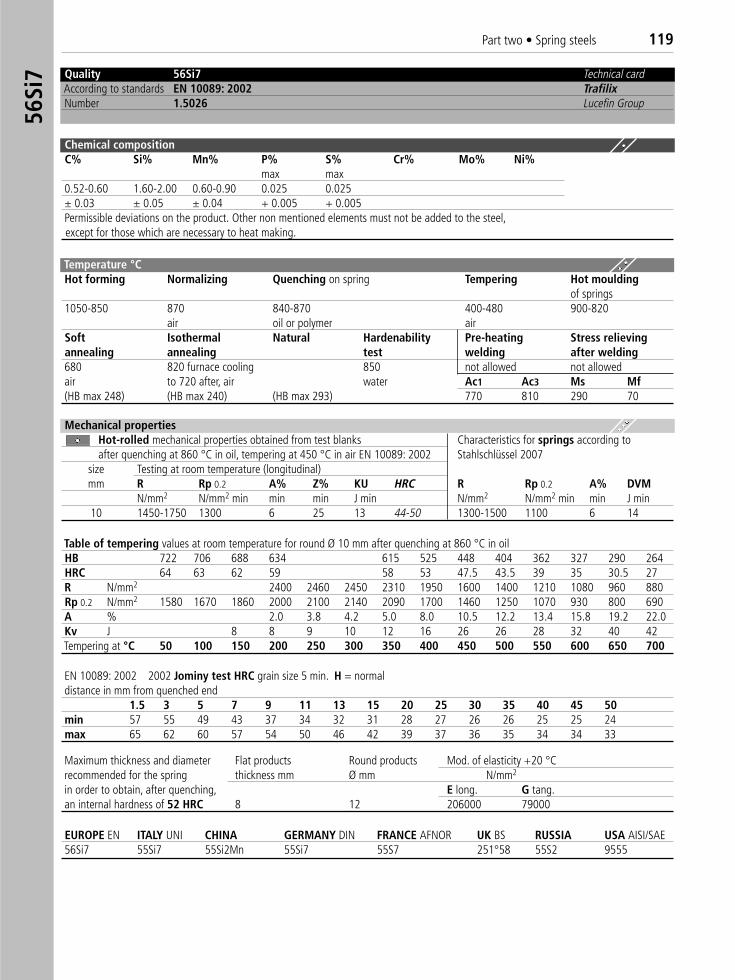
Part two • Spring steels 11956
Si7 Quality 56Si7 Technical card
According to standards EN 10089: 2002 TrafilixNumber 1.5026 Lucefin Group
Chemical compositionC% Si% Mn% P% S% Cr% Mo% Ni%
max max0.52-0.60 1.60-2.00 0.60-0.90 0.025 0.025± 0.03 ± 0.05 ± 0.04 + 0.005 + 0.005Permissible deviations on the product. Other non mentioned elements must not be added to the steel,except for those which are necessary to heat making.
Temperature °C Hot forming Normalizing Quenching on spring Tempering Hot moulding
of springs1050-850 870 840-870 400-480 900-820
air oil or polymer airSoft Isothermal Natural Hardenability Pre-heating Stress relievingannealing annealing test welding after welding680 820 furnace cooling 850 not allowed not allowedair to 720 after, air water Ac1 Ac3 Ms Mf(HB max 248) (HB max 240) (HB max 293) 770 810 290 70
Mechanical propertiesHot-rolled mechanical properties obtained from test blanks Characteristics for springs according toafter quenching at 860 °C in oil, tempering at 450 °C in air EN 10089: 2002 Stahlschlüssel 2007
size Testing at room temperature (longitudinal)mm R Rp 0.2 A% Z% KU HRC R Rp 0.2 A% DVM
N/mm2 N/mm2 min min min J min N/mm2 N/mm2 min min J min10 1450-1750 1300 6 25 13 44-50 1300-1500 1100 6 14
Table of tempering values at room temperature for round Ø 10 mm after quenching at 860 °C in oilHB 722 706 688 634 615 525 448 404 362 327 290 264HRC 64 63 62 59 58 53 47.5 43.5 39 35 30.5 27R N/mm2 2400 2460 2450 2310 1950 1600 1400 1210 1080 960 880Rp 0.2 N/mm2 1580 1670 1860 2000 2100 2140 2090 1700 1460 1250 1070 930 800 690A % 2.0 3.8 4.2 5.0 8.0 10.5 12.2 13.4 15.8 19.2 22.0Kv J 8 8 9 10 12 16 26 26 28 32 40 42Tempering at °C 50 100 150 200 250 300 350 400 450 500 550 600 650 700
Maximum thickness and diameter Flat products Round products Mod. of elasticity +20 °Crecommended for the spring thickness mm Ø mm N/mm2
in order to obtain, after quenching, E long. G tang.an internal hardness of 52 HRC 8 12 206000 79000
EUROPE EN ITALY UNI CHINA GERMANY DIN FRANCE AFNOR UK BS RUSSIA USA AISI/SAE 56Si7 55Si7 55Si2Mn 55Si7 55S7 251°58 55S2 9555
EN 10089: 2002 2002 Jominy test HRC grain size 5 min. H = normaldistance in mm from quenched end
1.5 3 5 7 9 11 13 15 20 25 30 35 40 45 50min 57 55 49 43 37 34 32 31 28 27 26 26 25 25 24max 65 62 60 57 54 50 46 42 39 37 36 35 34 34 33
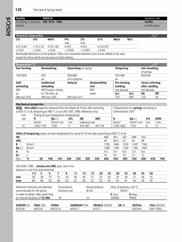
120 Part two • Spring steels60
SiCr
8 Quality 60SiCr8 Technical cardAccording to standards UNI 3545: 1980 TrafilixNumber Lucefin Group
Chemical compositionC% Si% Mn% P% S% Cr% Mo% Ni%
max max0.57-0.64 1.70-2.20 0.70-1.00 0.035 0.035 0.25-0.40± 0.03 ± 0.05 ± 0.04 + 0.005 + 0.005 ± 0.04Permissible deviations on the product. Other non mentioned elements must not be added to the steel,except for those which are necessary to heat making.
Temperature °C Hot forming Normalizing Quenching on spring Tempering Hot moulding
of springs1050-850 870 830-860 430-480 920-830
air oil or polymer airSoft Isothermal Natural Hardenability Pre-heating Stress relievingannealing annealing test welding after welding680 820 furnace cooling 850 not allowed not allowedair to 720 after, air water Ac1 Ac3 Ms Mf(HB max 255) (HB max 250) (HB max 321) 770 800 270 50
Mechanical propertiesHot-rolled properties obtained from test blanks Ø 10 mm after quenching Characteristics for springs according to
at 850 °C in oil, tempering at 480 °C in air. UNI 3545: 1980. Reference only. Stahlschlüssel 2007size Testing at room temperature (longitudinal)mm R Rp 0.2 A% HB HRC R Rp 0.2 A% DVM
N/mm2 N/mm2 min min reference only N/mm2 N/mm2 min min J min10 1450-1700 1250 5 415-467 44.5-49 1350-1600 1150 6 21
Table of tempering values at room temperature for round Ø 10 mm after quenching at 850 °C in oilHB 468 461 442 409 353HRC 49 48.5 47 44 38R N/mm2 1700 1660 1570 1420 1160Rp 0.2 N/mm2 1390 1340 1240 1180 1000A % 4.5 5.0 6.0 7.0 9.0Kv J 10 10 10 12 12Rinv. °C 50 100 150 200 250 300 350 400 450 500 550 600 650 700
Maximum thickness and diameter Flat products Round products Mod. of elasticity +20 °Crecommended for the spring thickness mm Ø mm N/mm2
in order to obtain, after quenching, E long. G tang.an internal hardness of 52 HRC 16 24 206000 79000
EUROPE EN ITALY UNI CHINA GERMANY DIN FRANCE AFNOR UK BS RUSSIA USA AISI/SAE 60SiCr8 60SiCr8 60Si2CrA 60SiCr7 61SC7 60S2HA 9261-9262
UNI 3545: 1980 Jominy test HRC grain size 5 min.distance in mm from quenched end
1.5 3 5 7 9 11 13 15 20 25 30 35 40 45 50min 58 58 57 51 45 40 38 37 33 30 29 28 27 26 25max 66 66 65 64 63 61 59 57 50 45 43 41 40 39 39
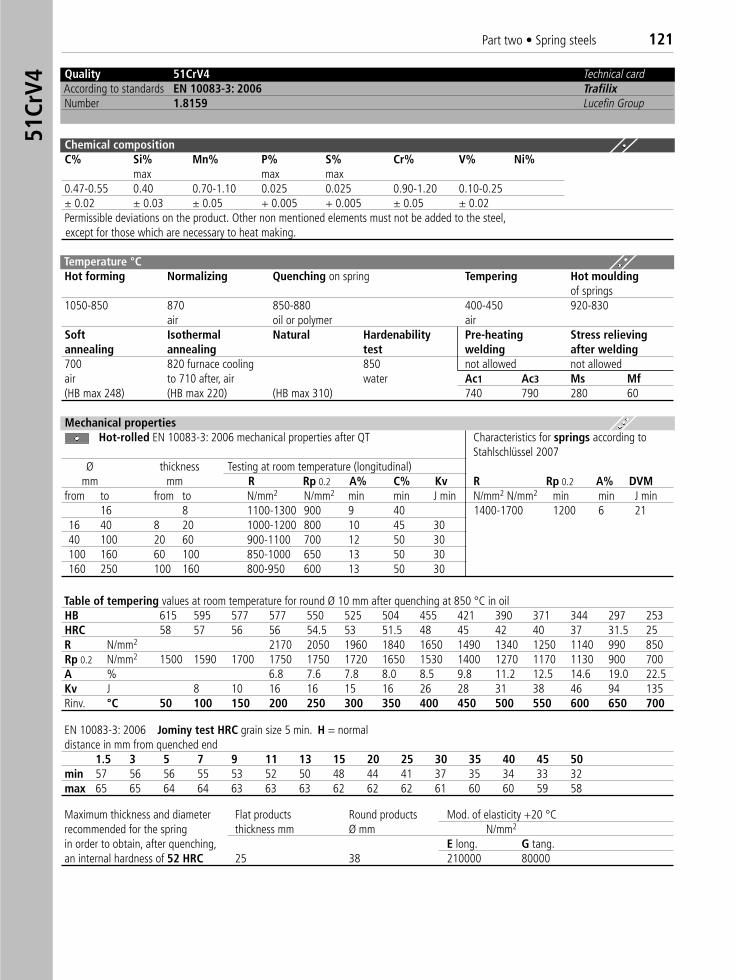
Part two • Spring steels 12151
CrV4
Quality 51CrV4 Technical cardAccording to standards EN 10083-3: 2006 TrafilixNumber 1.8159 Lucefin Group
Chemical compositionC% Si% Mn% P% S% Cr% V% Ni%
max max max0.47-0.55 0.40 0.70-1.10 0.025 0.025 0.90-1.20 0.10-0.25 ± 0.02 ± 0.03 ± 0.05 + 0.005 + 0.005 ± 0.05 ± 0.02Permissible deviations on the product. Other non mentioned elements must not be added to the steel,except for those which are necessary to heat making.
Temperature °C Hot forming Normalizing Quenching on spring Tempering Hot moulding
of springs1050-850 870 850-880 400-450 920-830
air oil or polymer airSoft Isothermal Natural Hardenability Pre-heating Stress relievingannealing annealing test welding after welding700 820 furnace cooling 850 not allowed not allowedair to 710 after, air water Ac1 Ac3 Ms Mf(HB max 248) (HB max 220) (HB max 310) 740 790 280 60
Mechanical propertiesHot-rolled EN 10083-3: 2006 mechanical properties after QT Characteristics for springs according to
Stahlschlüssel 2007Ø thickness Testing at room temperature (longitudinal)
mm mm R Rp 0.2 A% C% Kv R Rp 0.2 A% DVMfrom to from to N/mm2 N/mm2 min min J min N/mm2 N/mm2 min min J min
16 8 1100-1300 900 9 40 1400-1700 1200 6 2116 40 8 20 1000-1200 800 10 45 3040 100 20 60 900-1100 700 12 50 30100 160 60 100 850-1000 650 13 50 30160 250 100 160 800-950 600 13 50 30
Table of tempering values at room temperature for round Ø 10 mm after quenching at 850 °C in oilHB 615 595 577 577 550 525 504 455 421 390 371 344 297 253HRC 58 57 56 56 54.5 53 51.5 48 45 42 40 37 31.5 25R N/mm2 2170 2050 1960 1840 1650 1490 1340 1250 1140 990 850Rp 0.2 N/mm2 1500 1590 1700 1750 1750 1720 1650 1530 1400 1270 1170 1130 900 700A % 6.8 7.6 7.8 8.0 8.5 9.8 11.2 12.5 14.6 19.0 22.5Kv J 8 10 16 16 15 16 26 28 31 38 46 94 135Rinv. °C 50 100 150 200 250 300 350 400 450 500 550 600 650 700
EN 10083-3: 2006 Jominy test HRC grain size 5 min. H = normaldistance in mm from quenched end
1.5 3 5 7 9 11 13 15 20 25 30 35 40 45 50min 57 56 56 55 53 52 50 48 44 41 37 35 34 33 32max 65 65 64 64 63 63 63 62 62 62 61 60 60 59 58
Maximum thickness and diameter Flat products Round products Mod. of elasticity +20 °Crecommended for the spring thickness mm Ø mm N/mm2
in order to obtain, after quenching, E long. G tang.an internal hardness of 52 HRC 25 38 210000 80000
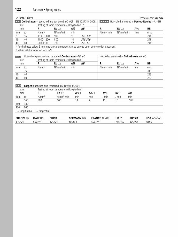
EUROPE EN ITALY UNI CHINA GERMANY DIN FRANCE AFNOR UK BS RUSSIA USA AISI/SAE 51CrV4 50CrV4 50CrV4 50CrV4 50CrV4 735A50 50ChGF 6150
51CrV4 1.8159 Technical card TrafilixCold-drawn + quenched and tempered +C +QT EN 10277-5: 2008 Hot-rolled annealed + Peeled-Reeled +A +SH
size Testing at room temperature (longitudinal) e)
mm R Rp 0.2 A% HB R Rp 0.2 A% HBfrom to N/mm2 N/mm2 min min N/mm2 min N/mm2 min min maxb) 16 1100-1300 900 9 331-380 24816 40 1000-1200 800 10 298-359 24840 80 900-1100 700 12 271-331 248b) for thickness below 5 mm mechanical properties can be agreed upon before order placemente) values valid also for +C +QT +SL
Hot-rolled quenched and tempered Cold-drawn +QT +C Hot-rolled annealed + Cold-drawn +A +Csize Testing at room temperature (longitudinal) mm R Rp 0.2 A% HB R Rp 0.2 A% HB
from to N/mm2 N/mm2 min min N/mm2 min N/mm2 min min max16 311
16 40 29340 80 287
Forged quenched and tempered EN 10250-3: 2001size Testing at room temperature (longitudinal)mm R Rp 0.2 A% L A% T Kv L Kv T HB
from to N/mm2 N/mm2 min min min J min J min min160 800 600 13 9 30 16 240
160 330330 660L = longitudinal T = tangential
122 Part two • Spring steels
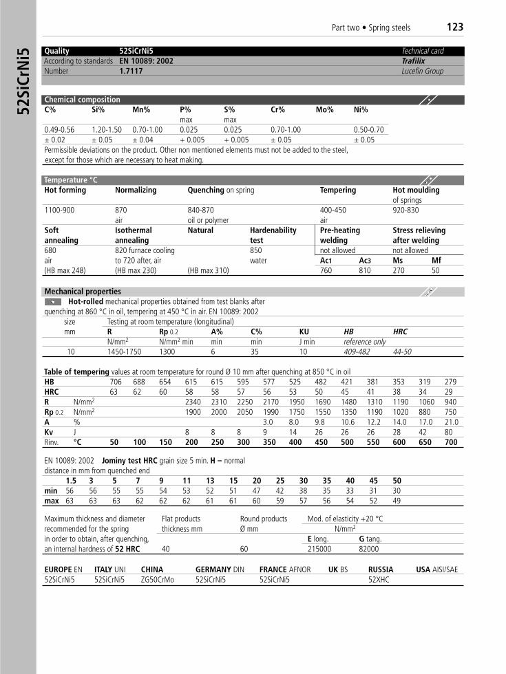
Quality 52SiCrNi5 Technical cardAccording to standards EN 10089: 2002 TrafilixNumber 1.7117 Lucefin Group
Chemical compositionC% Si% Mn% P% S% Cr% Mo% Ni%
max max0.49-0.56 1.20-1.50 0.70-1.00 0.025 0.025 0.70-1.00 0.50-0.70± 0.02 ± 0.05 ± 0.04 + 0.005 + 0.005 ± 0.05 ± 0.05Permissible deviations on the product. Other non mentioned elements must not be added to the steel,except for those which are necessary to heat making.
Temperature °C Hot forming Normalizing Quenching on spring Tempering Hot moulding
of springs1100-900 870 840-870 400-450 920-830
air oil or polymer airSoft Isothermal Natural Hardenability Pre-heating Stress relievingannealing annealing test welding after welding680 820 furnace cooling 850 not allowed not allowedair to 720 after, air water Ac1 Ac3 Ms Mf(HB max 248) (HB max 230) (HB max 310) 760 810 270 50
Mechanical propertiesHot-rolled mechanical properties obtained from test blanks after �
quenching at 860 °C in oil, tempering at 450 °C in air. EN 10089: 2002size Testing at room temperature (longitudinal)mm R Rp 0.2 A% C% KU HB HRC
N/mm2 N/mm2 min min min J min reference only10 1450-1750 1300 6 35 10 409-482 44-50
Table of tempering values at room temperature for round Ø 10 mm after quenching at 850 °C in oil HB 706 688 654 615 615 595 577 525 482 421 381 353 319 279HRC 63 62 60 58 58 57 56 53 50 45 41 38 34 29R N/mm2 2340 2310 2250 2170 1950 1690 1480 1310 1190 1060 940Rp 0.2 N/mm2 1900 2000 2050 1990 1750 1550 1350 1190 1020 880 750A % 3.0 8.0 9.8 10.6 12.2 14.0 17.0 21.0Kv J 8 8 8 9 14 26 26 26 28 42 80Rinv. °C 50 100 150 200 250 300 350 400 450 500 550 600 650 700
Maximum thickness and diameter Flat products Round products Mod. of elasticity +20 °Crecommended for the spring thickness mm Ø mm N/mm2
in order to obtain, after quenching, E long. G tang.an internal hardness of 52 HRC 40 60 215000 82000
EUROPE EN ITALY UNI CHINA GERMANY DIN FRANCE AFNOR UK BS RUSSIA USA AISI/SAE 52SiCrNi5 52SiCrNi5 ZG50CrMo 52SiCrNi5 52SiCrNi5 52XHC
EN 10089: 2002 Jominy test HRC grain size 5 min. H = normaldistance in mm from quenched end
1.5 3 5 7 9 11 13 15 20 25 30 35 40 45 50min 56 56 55 55 54 53 52 51 47 42 38 35 33 31 30max 63 63 63 62 62 62 61 61 60 59 57 56 54 52 49
52Si
CrN
i5Part two • Spring steels 123
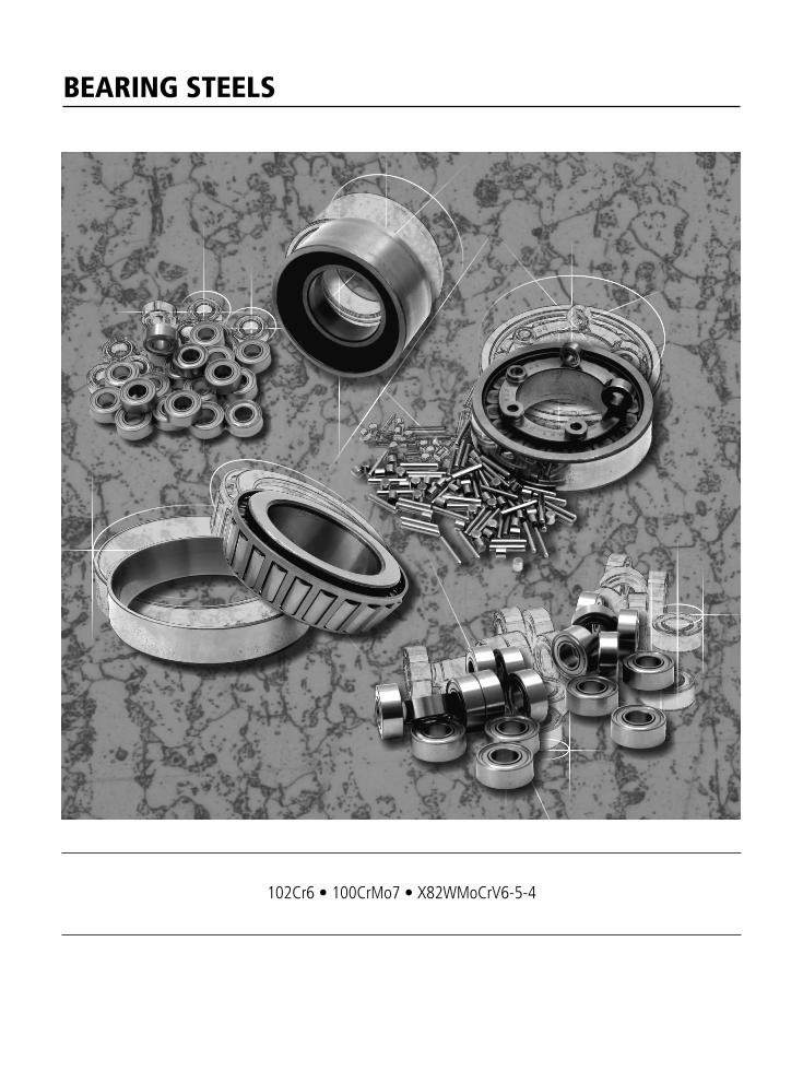
BEARING STEELS
102Cr6 • 100CrMo7 • X82WMoCrV6-5-4
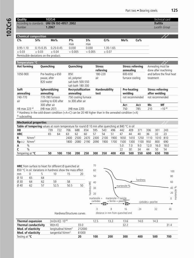
Part two • Bearing steels 12510
2Cr6 Quality 102Cr6 Technical card
According to standards UNI EN ISO 4957: 2002 TrafilixNumber 1.2067 Lucefin Group
Chemical compositionC% Si% Mn% P% S% Cr% Mo% Cu%
max max0.95-1.10 0.15-0.35 0.25-0.45 0.030 0.030 1.35-1.65± 0.03 ± 0.03 ± 0.04 + 0.005 + 0.005 ± 0.07Permissible deviations on the product.
Temperature °C Hot forming Quenching Quenching Stress Stress relieving Annealing must be
relieving annealing done after machining 1050-900 Pre-heating a 650 850 180-220 600-650 and before the final heat
pause, after oil, polymer air furnace cooling treatment820 water salt bath 500-550
salt bath 180-200Soft Spheroidizing Recrystallization Hardenability Pre-heating Stress relievingannealing annealing annealing test welding after welding740-770 770-780 furnace 750 cooling furnace not recommended not recommendedair cooling to 630 after to 300 after air
300 after air Ac1 Ac3 Ms MfHB max 223 a) (HB max 207) (HB max 220) 750 785 210 –10 b)
a) Hardness in the cold-drawn condition (+A+C) can be 20 HB higher than in the annealed condition (+A)b) subcooling
Mechanical propertiesTable of tempering values at room temperature for round Ø 10 mm after quenching at 840 °C in oilHB 739 722 706 688 654 595 543 496 442 409 371 336 301 243HRC 65 64 63 62 60 57 54 51 47 44 40 36 32 23R N/mm2 2400 2500 2470 2300 2100 1900 1650 1410 1250 1110 1010 810Rp 0.2 N/mm2 1800 2080 2190 2090 1900 1700 1500 1300 1100 950 800 690A % 5.0 7.0 9.0 12.0 16.0 18.0C % 22 30 34 44 50 54Tempering at °C 50 100 150 200 250 300 350 400 450 500 550 600 650 700
HRC from surface to heart for different Ø quenched at 850 °C in oil. Variations in hardness show the mass effectmm 0 5 10 15 20Ø 10 65 64Ø 30 64 62 59 58Ø 40 62 57 52.5 50.5 50
Thermal expansion [m/(m·K)] ·10–6 12.5 13.2 13.6 14.0 14.3Thermal conductivity W(m·K) 33.0 32.2 31.4Mod. of elasticity longitudinal N/mm2 212000Mod. of elasticity tangential N/mm2 81000Testing at °C 20 100 200 300 400 500 700
70
60
50
40
30
20
hardness
martensite %
martensite +carbides
distance in mm from quenched end
martensite + bainite+ ferrite + pearlite carbides+ pearlite
hard
ness
HRC
mar
tens
ite %40
20
0
100
80
60
0 8 16 24 32 40
Hardness/Structures curves
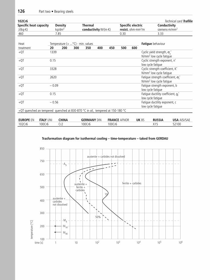
126 Part two • Bearing steels
Heat Temperature (+ ...°C) - min. values Fatigue behaviourtreatment 20 200 300 350 400 450 500 600+QT 1339 Cyclic yield strength, σy’
N/mm2 low cycle fatigue+QT 0.15 Cyclic strength exponent, n’
low cycle fatigue+QT 3328 Cyclic strength coefficient, K‘
N/mm2 low cycle fatigue+QT 2620 Fatigue strength coefficient, σf‘
N/mm2 low cycle fatigue+QT – 0.09 Fatigue strength exponent, b
low cycle fatigue+QT 0.15 Fatigue ductility coefficient, gf‘
low cycle fatigue+QT – 0.56 Fatigue ductility exponent, c
low cycle fatigue+QT quenched an tempered quenched at 830-870 °C in oil, tempered at 150-180 °C
102Cr6 Technical card TrafilixSpecific heat capacity Density Thermal Specific electric ConductivityJ/(kg·K) kg/dm3 conductivity W/(m·K) resist. ohm·mm2/m siemens·m/mm2
460 7.85 0.30 3.33
850
750
650
500
400
300
As
Ms
M50
M90
ferrite + carbides
1 10 102 103 104 105 106
10
time [s]
tem
pera
ture
[°C]
200
100
austenite +ferrite +carbides
austenite + carbides not dissolved
austenite +carbides not dissolved
50%
Trasformation diagram for isothermal cooling – time-temperature – taked from GERDAU
EUROPE EN ITALY UNI CHINA GERMANY DIN FRANCE AFNOR UK BS RUSSIA USA AISI/SAE 102Cr6 100Cr6 Cr2 100Cr6 100Cr6 X15 52100
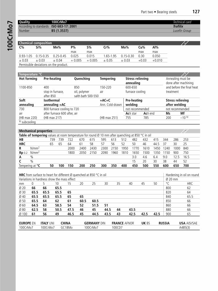
Part two • Bearing steels 12710
0CrM
o7
Quality 100CrMo7 Technical cardAccording to standards ISO 683-17: 2001 TrafilixNumber B5 (1.3537) Lucefin Group
Chemical compositionC% Si% Mn% P% S% Cr% Mo% Cu% Al%
max max max max0.93-1.05 0.15-0.35 0.25-0.45 0.025 0.015 1.65-1.95 0.15-0.30 0.30 0.050± 0.03 ± 0.03 ± 0.04 + 0.005 + 0.005 ± 0.05 ± 0.03 +0.03 +0.010Permissible deviations on the product.
Temperature °C Hot forming Pre-heating Quenching Tempering Stress relieving Annealing must be
annealing done after machining1100-850 400 850 150-220 600-650 and before the final heat
stop in furnace, oil, polymer air furnace cooling treatmentafter 850 salth bath 500-550
Soft Isothermal +AC+C Pre-heating Stress relievingannealing annealing +AC Ann. Cold-drawn welding after welding730 800 furnace cooling to 720 not recommended not recommendedair after furnace 600 after, air Ac1 star Ac1 end Ms Mf(HB max 220) (HB max 217) (HB max 251) 755 785 200 –10 b)
b) subcooling
HRC from surface to heart for different Ø quenched at 850 °C in oil Hardening in oil on roundVariations in hardness show the mass effect Ø 20 mmmm 0 5 10 15 20 25 30 35 40 45 50 °C HRCØ 20 66 66 65.5 800 62Ø 30 65.5 65.5 65.5 65 820 64Ø 40 65.5 65.5 65.5 65 65 840 65.5Ø 50 65.5 64 62 61 60.5 60.5 850 66Ø 60 64.5 63 58.5 54 52 51.5 51 860 66Ø 80 62.5 58 50.5 47.5 46 45 44.5 44 43.5 880 66Ø 100 61 56 49 46.5 45 44.5 43.5 43 42.5 42.5 42.5 900 65
EUROPE EN ITALY UNI CHINA GERMANY DIN FRANCE AFNOR UK BS RUSSIA USA AISI/SAE100CrMo7 100CrMo7 GC18Mo 100CrMo7 100CD7 A485(3)
Mechanical propertiesTable of tempering values at room temperature for round Ø 10 mm after quenching at 850 °C in oilHB 739 739 722 670 615 595 613 512 482 432 415 344 286 253HRC 65 65 64 61 58 57 56 52 50 46 44.5 37 30 25R N/mm2 2000 2400 2430 2300 2150 1950 1770 1610 1450 1240 1000 840Rp 0.2 N/mm2 1800 2050 2150 2090 1960 1810 1650 1500 1350 1150 900 750A % 3.0 4.6 6.4 9.0 12.5 16.5C % 15 20 30 38 44 52Tempering at °C 50 100 150 200 250 300 350 400 450 500 550 600 650 700
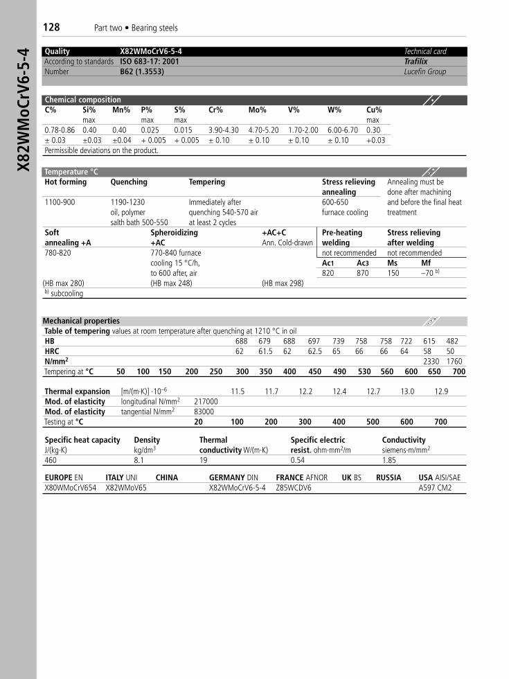
X82W
MoC
rV6-
5-4
128 Part two • Bearing steels
Quality X82WMoCrV6-5-4 ) Technical cardAccording to standards ISO 683-17: 2001 TrafilixNumber B62 (1.3553) Lucefin Group
Chemical compositionC% Si% Mn% P% S% Cr% Mo% V% W% Cu%
max max max max0.78-0.86 0.40 0.40 0.025 0.015 3.90-4.30 4.70-5.20 1.70-2.00 6.00-6.70 0.30± 0.03 ±0.03 ±0.04 + 0.005 + 0.005 ± 0.10 ± 0.10 ± 0.10 ± 0.10 +0.03Permissible deviations on the product.
Temperature °C Hot forming Quenching Tempering Stress relieving Annealing must be
annealing done after machining 1100-900 1190-1230 Immediately after 600-650 and before the final heat
oil, polymer quenching 540-570 air furnace cooling treatmentsalth bath 500-550 at least 2 cycles
Soft Spheroidizing +AC+C Pre-heating Stress relievingannealing +A +AC Ann. Cold-drawn welding after welding780-820 770-840 furnace not recommended not recommended
cooling 15 °C/h, Ac1 Ac3 Ms Mfto 600 after, air 820 870 150 –70 b)
(HB max 280) (HB max 248) (HB max 298)b) subcooling
Mechanical propertiesTable of tempering values at room temperature after quenching at 1210 °C in oilHB 688 679 688 697 739 758 758 722 615 482HRC 62 61.5 62 62.5 65 66 66 64 58 50N/mm2 2330 1760Tempering at °C 50 100 150 200 250 300 350 400 450 490 530 560 600 650 700
Thermal expansion [m/(m·K)] ·10–6 11.5 11.7 12.2 12.4 12.7 13.0 12.9Mod. of elasticity longitudinal N/mm2 217000Mod. of elasticity tangential N/mm2 83000Testing at °C 20 100 200 300 400 500 600 700
Specific heat capacity Density Thermal Specific electric ConductivityJ/(kg·K) kg/dm3 conductivity W/(m·K) resist. ohm·mm2/m siemens·m/mm2
460 8.1 19 0.54 1.85
EUROPE EN ITALY UNI CHINA GERMANY DIN FRANCE AFNOR UK BS RUSSIA USA AISI/SAE X80WMoCrV654 X82WMoV65 X82WMoCrV6-5-4 Z85WCDV6 A597 CM2
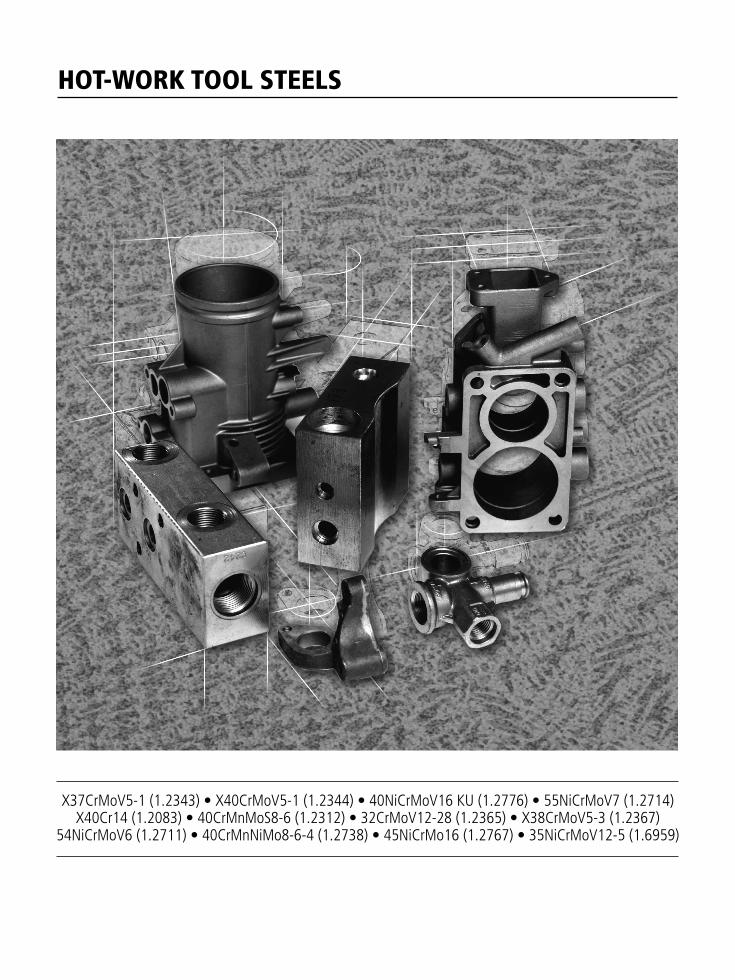
HOT-WORK TOOL STEELS
X37CrMoV5-1 (1.2343) • X40CrMoV5-1 (1.2344) • 40NiCrMoV16 KU (1.2776) • 55NiCrMoV7 (1.2714)X40Cr14 (1.2083) • 40CrMnMoS8-6 (1.2312) • 32CrMoV12-28 (1.2365) • X38CrMoV5-3 (1.2367)
54NiCrMoV6 (1.2711) • 40CrMnNiMo8-6-4 (1.2738) • 45NiCrMo16 (1.2767) • 35NiCrMoV12-5 (1.6959)
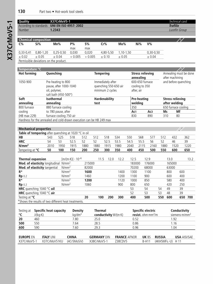
130 Part two • Hot-work tool steelsX3
7CrM
oV5-
1 Quality X37CrMoV5-1 Technical cardAccording to standards UNI EN ISO 4957: 2002 TrafilixNumber 1.2343 Lucefin Group
Chemical compositionC% Si% Mn% P% S% Cr% Mo% Ni% V%
max max0,33-0,41 0,80-1,20 0,25-0,50 0,030 0,020 4,80-5,50 1,10-1,50 0,30-0,50± 0.02 ± 0.05 ± 0.04 + 0.005 + 0.005 ± 0.10 ± 0.05 ± 0.04Permissible deviations on the product.
Temperature °CHot forming Quenching Tempering Stress relieving Annealing must be done
annealing after machining1050-900 Pre-heating to 800 Immediately after 600-650 furnace and before quenching
pause, after 1000-1040 quenching 550-650 air cooling to 350oil, polymer, minimum 2 cycles after, airsalt bath (450-500°)
Soft Isothermal Hardenability Pre-heating Stress relievingannealing annealing test welding after welding800 furnace 880 furnace cooling 350 650 furnace coolingcooling to 780 pause, after Ac1 Ac3 Ms Mf(HB max 229) furnace cooling 750 air 830 890 310 80Hardness for the annealed and cold-drawn execution can be HB 249 max
Thermal expansion [m/(m·K)] · 10–6 11.5 12.0 12.2 12.5 12.9 13.0 13.2Mod. of elasticity longitudinal N/mm2 215000 183000 176000 165000Mod. of elasticity tangential N/mm2 82000 70200 68000 63000R* N/mm2 1600 1400 1300 1100 800 600Rp 0.2 N/mm2 1460 1200 1100 900 600 400R* N/mm2 1200 1120 1000 850 580 400Rp 0.2 N/mm2 1060 900 800 650 420 250HRC quenching 1040 °C oil 53 54 54 49 39HRC quenching 1040 °C air 52 53 53 48 39Testing at °C 20 100 200 300 400 500 550 600 650 700*Shows the results of two different heat treatments.
EUROPE EN ITALY UNI CHINA GERMANY DIN FRANCE AFNOR UK BS RUSSIA USA AISI/SAEX37CrMoV5-1 X37CrMoV51KU (4Cr5MoSiV) X38CrMoV5-1 Z38CDV5 B-H11 (4KH5MFs.-U) H 11
Mechanical propertiesTable of tempering after quenching at 1020 °C in oilHB 543 525 518 512 512 518 534 550 568 577 512 432 362HRC 54 53 52.5 52 52 52.5 53.5 54.5 55.5 56 52 46 39N/mm2 2010 1950 1915 1880 1880 1915 1980 2040 2115 2160 1880 1520 1220Tempering at °C 50 100 150 200 250 300 350 400 450 500 550 600 650
Testing at Specific heat capacity Density Thermal Specific electric Conductivity°C J/(kg·K) kg/dm3 conductivity W/(m·K) resist. ohm·mm2/m siemens·m/mm2
20 460 7.80 25.0 0.52 1.92500 550 7.64 28.5 0.86 1.16600 590 7.60 29.3 0.96 1.04
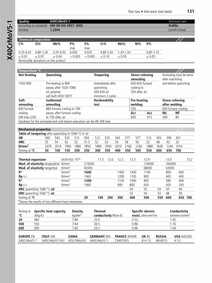
Part two • Hot-work tool steels 131X4
0CrM
oV5-
1 Quality X40CrMoV5-1 Technical cardAccording to standards UNI EN ISO 4957: 2002 TrafilixNumber 1.2344 Lucefin Group
Chemical compositionC% Si% Mn% P% S% Cr% Mo% Ni% V%
max max0,35-0,42 0,80-1,20 0,25-0,50 0,030 0,020 4,80-5,50 1,20-1,50 0,85-1,15± 0.02 ± 0.05 ± 0.04 + 0.005 + 0.005 ± 0.10 ± 0.05 ± 0.05Permissible deviations on the product.
Temperature °C Hot forming Quenching Tempering Stress relieving Annealing must be done
annealing after machining1050-900 Pre-heating to 800 Immediately after 600-650 furnace and before quenching
pause, after 1020-1080 quenching cooling tooil, polymer, 500-620 air 350 after, airsalt bath (450-500°) minimum 2 cycles
Soft Isothermal Hardenability Pre-heating Stress relievingannealing annealing test welding after welding820 furnace 880 furnace cooling to 780 350 650 furnace coolingcooling pause, after furnace cooling Ac1 Ac3 Ms Mf(HB max 229) to 750 after, air 830 915 300 80Hardness for the annealed and cold-drawn execution can be HB 249 max
Thermal expansion [m/(m·K)] ·10–6 11.5 12.0 12.2 12.5 12.9 13.0 13.2Mod. of elasticity longitudinal N/mm2 215000 176000 165000Mod. of elasticity tangential N/mm2 82000 68000 63000R* N/mm2 1600 1400 1300 1100 800 600Rp 0.2 N/mm2 1460 1200 1100 900 600 400R* N/mm2 1200 1120 1000 850 580 400Rp 0.2 N/mm2 1060 900 800 650 420 250HRC quenching 1040 °C oil 54 55 54 50 40HRC quenching 1040 °C air 53 54 53 48 39Testing at °C 20 100 200 300 400 500 550 600 650 700*Shows the results of two different heat treatments.
EUROPE EN ITALY UNI CHINA GERMANY DIN FRANCE AFNOR UK BS RUSSIA USA AISI/SAE X40CrMoV5-1 X40CrMoV511KU (45Cr5MoSiV) X40CrMoV5-1 Z340CDV5 B-H 13 4KH5F1S H 13
Mechanical propertiesTable of tempering after quenching at 1040 °C in oilHB 560 543 525 512 504 512 525 543 577 577 512 455 390 301HRC 55 54 53 52 51.5 52 53 54 56 56 52 48 42 32N/mm2 2070 2010 1950 1880 1850 1880 1950 2010 2160 2160 1880 1640 1340 1010Testing at °C 50 100 150 200 250 300 350 400 450 500 550 600 650 700
Testing at Specific heat capacity Density Thermal Specific electric Conductivity°C J/(kg·K) kg/dm3 conductivity W/(m·K) resist. ohm·mm2/m siemens·m/mm2
20 460 7.80 25.0 0.52 1.92500 550 7.64 28.5 0.86 1.16600 590 7.60 29.3 0.96 1.04
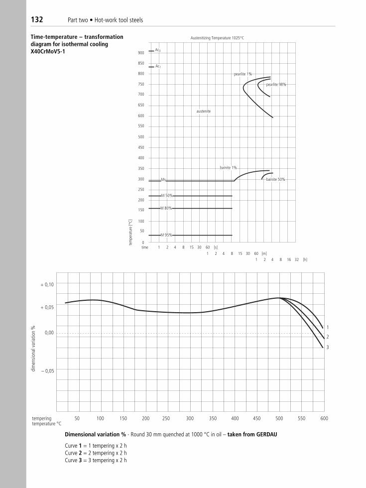
Austenitizing Temperature 1025 C
pearlite 1%
pearlite 98%
austenite
bainite 1%
bainite 50%Ms
M 50%
M 80%
M 95%
Ac3
Ac1
900
850
800
750
700
650
600
550
500
450
400
350
300
250
200
150
100
50
01 2 4 8 15 30 60 [s]
1 2 4 8 15 30 60 [m]1 2 4 8 16 32 [h]
time
tem
pera
ture
[C]
+ 0,10
+ 0,05
0,00
– 0,05
50 100 150 200 250 300 350 400 450 500 550 600
1
2
3
temperingtemperature °C
dim
ensio
nal v
aria
tion
%Time-temperature – transformationdiagram for isothermal coolingX40CrMoV5-1
Dimensional variation % - Round 30 mm quenched at 1000 °C in oil – taken from GERDAU
Curve 1 = 1 tempering x 2 hCurve 2 = 2 tempering x 2 hCurve 3 = 3 tempering x 2 h
132 Part two • Hot-work tool steels
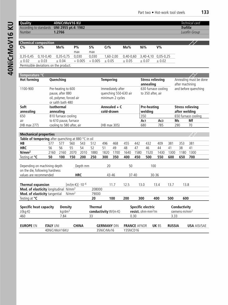
EUROPE EN ITALY UNI CHINA GERMANY DIN FRANCE AFNOR UK BS RUSSIA USA AISI/SAE40NiCrMoV16KU 35NiCrMo16 Y35NCD16
Mechanical propertiesTable of tempering after quenching at 880 °C in oilHB 577 577 560 543 512 496 468 455 442 432 409 381 353 381HRC 56 56 55 54 52 51 49 48 47 46 44 41 38 41N/mm2 2160 2160 2070 2010 1880 1820 1700 1640 1580 1520 1430 1300 1180 1300Testing at °C 50 100 150 200 250 300 350 400 450 500 550 600 650 700
Quality 40NiCrMoV16 KU Technical cardAccording to standards UNI 2955 pt.4: 1982 TrafilixNumber 1.2766 Lucefin Group
Chemical compositionC% Si% Mn% P% S% Cr% Mo% Ni% V%
max max0,35-0,45 0,10-0,40 0,35-0,75 0,030 0,030 1,60-2,00 0,40-0,60 3,40-4,10 0,05-0,25± 0.02 ± 0.03 ± 0.04 + 0.005 + 0.005 ± 0.05 ± 0.05 ± 0.07 ± 0.02Permissible deviations on the product.
Depending on machining depth Depth mm 20 50 100on the die, following hardnessvalues are recommended HRC 43-46 37-40 30-36
Thermal expansion [m/(m·K)] ·10–6 11.7 12.5 13.0 13.4 13.7 13.8Mod. of elasticity longitudinal N/mm2 208000Mod. of elasticity tangential N/mm2 79000Testing at °C 20 100 200 300 400 500 600
Specific heat capacity Density Thermal Specific electric ConductivityJ/(kg·K) kg/dm3 conductivity W/(m·K) resist. ohm·mm2/m siemens·m/mm2
460 7.84 33 0.30 3.33
Temperature °C Hot forming Quenching Tempering Stress relieving Annealing must be done
annealing after machining1100-900 Pre-heating to 600 Immediately after 630 furnace cooling and before quenching
pause, after 880 quenching 550-630 air to 350 after, airoil, polymer, forced air minimum 2 cyclesor salth bath 480
Soft Isothermal Annealed + C Pre-heating Stress relievingannealing annealing cold-drawn welding after welding650 810 furnace cooling 350 650 furnace coolingair to 610 pause, furnace Ac1 Ac3 Ms Mf(HB max 277) cooling to 580 after, air (HB max 305) 680 785 290 70
40N
iCrM
oV16
KU
Part two • Hot-work tool steels 133
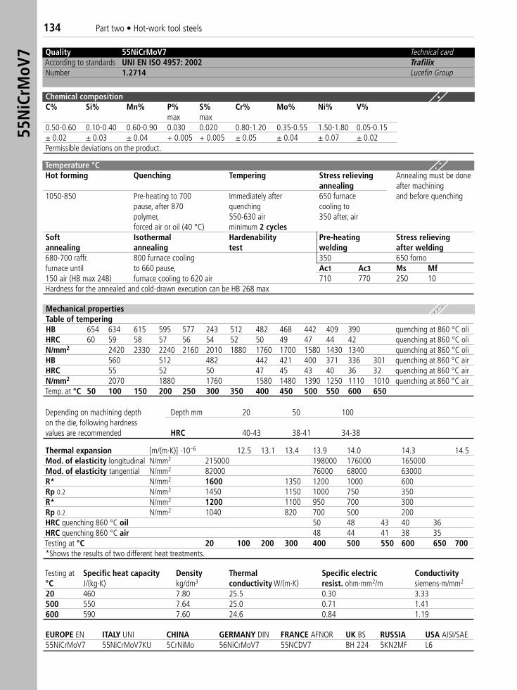
Quality 55NiCrMoV7 Technical cardAccording to standards UNI EN ISO 4957: 2002 TrafilixNumber 1.2714 Lucefin Group
Chemical compositionC% Si% Mn% P% S% Cr% Mo% Ni% V%
max max0.50-0.60 0.10-0.40 0.60-0.90 0.030 0.020 0.80-1.20 0.35-0.55 1.50-1.80 0.05-0.15± 0.02 ± 0.03 ± 0.04 + 0.005 + 0.005 ± 0.05 ± 0.04 ± 0.07 ± 0.02Permissible deviations on the product.
Temperature °CHot forming Quenching Tempering Stress relieving Annealing must be done
annealing after machining1050-850 Pre-heating to 700 Immediately after 650 furnace and before quenching
pause, after 870 quenching cooling topolymer, 550-630 air 350 after, airforced air or oil (40 °C) minimum 2 cycles
Soft Isothermal Hardenability Pre-heating Stress relievingannealing annealing test welding after welding680-700 raffr. 800 furnace cooling 350 650 fornofurnace until to 660 pause, Ac1 Ac3 Ms Mf150 air (HB max 248) furnace cooling to 620 air 710 770 250 10 Hardness for the annealed and cold-drawn execution can be HB 268 max
Mechanical propertiesTable of temperingHB 654 634 615 595 577 243 512 482 468 442 409 390 quenching at 860 °C oliHRC 60 59 58 57 56 54 52 50 49 47 44 42 quenching at 860 °C oliN/mm2 2420 2330 2240 2160 2010 1880 1760 1700 1580 1430 1340 quenching at 860 °C oliHB 560 512 482 442 421 400 371 336 301 quenching at 860 °C airHRC 55 52 50 47 45 43 40 36 32 quenching at 860 °C airN/mm2 2070 1880 1760 1580 1480 1390 1250 1110 1010 quenching at 860 °C airTemp. at °C 50 100 150 200 250 300 350 400 450 500 550 600 650
Depending on machining depth Depth mm 20 50 100on the die, following hardnessvalues are recommended HRC 40-43 38-41 34-38
Thermal expansion [m/(m·K)] ·10–6 12.5 13.1 13.4 13.9 14.0 14.3 14.5Mod. of elasticity longitudinal N/mm2 215000 198000 176000 165000Mod. of elasticity tangential N/mm2 82000 76000 68000 63000R* N/mm2 1600 1350 1200 1000 600Rp 0.2 N/mm2 1450 1150 1000 750 350R* N/mm2 1200 1100 950 700 300Rp 0.2 N/mm2 1040 820 700 500 200HRC quenching 860 °C oil 50 48 43 40 36HRC quenching 860 °C air 48 44 41 38 35Testing at °C 20 100 200 300 400 500 550 600 650 700*Shows the results of two different heat treatments.
EUROPE EN ITALY UNI CHINA GERMANY DIN FRANCE AFNOR UK BS RUSSIA USA AISI/SAE55NiCrMoV7 55NiCrMoV7KU 5CrNiMo 56NiCrMoV7 55NCDV7 BH 224 5KN2MF L6
Testing at Specific heat capacity Density Thermal Specific electric Conductivity°C J/(kg·K) kg/dm3 conductivity W/(m·K) resist. ohm·mm2/m siemens·m/mm2
20 460 7.80 25.5 0.30 3.33500 550 7.64 25.0 0.71 1.41600 590 7.60 24.6 0.84 1.19
55N
iCrM
oV7
134 Part two • Hot-work tool steels
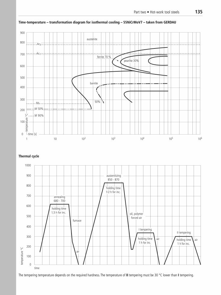
austenite
ferrite 70 %pearlite 30%
bainite
50%
Ac3
Ac1
Ms
M 50%
M 90%
1 10 102 103 104 105 106
100
200
300
400
500
600
700
800
900
0 time [s]
tem
pera
ture
C
1000
900
800
700
600
500
400
300
200
100
0
annealing680 - 700
holding time1,5 h for inc.
holding time1/2 h for inc.
holding time1 h for inc.
holding time1 h for inc.
austenitizing850 - 870
oil, polymerforced air
I temperingII tempering
air air
air
furnace
time
tem
pera
ture
C
Time-temperature – transformation diagram for isothermal cooling – 55NiCrMoV7 – taken from GERDAU
The tempering temperature depends on the required hardness. The temperature of II tempering must be 30 °C lower than I tempering.
Thermal cycle
Part two • Hot-work tool steels 135

Quality X40Cr14 Technical cardAccording to standards UNI EN ISO 4957: 2002 TrafilixNumber 1.2083 Lucefin Group
Chemical compositionC% Si% Mn% P% S% Cr%
max max max max0.36-0,42 1.00 1.00 0.030 0.030 12.50-14.50± 0.03 ± 0.05 ± 0.04 + 0.005 ± 0.005 ± 0.15Permissible deviations on the product.
Temperature °CHot Pre-heating Quenching Tempering Temperingforming1110-850 850 pause ▲ 980-1010 180 see table
after ▲ oil or polymer (HRC 53)Soft Pre-heating Stress relievingannealing welding after welding750-800 slow cooling 300 550in furnace Ac1 Ms(HB max 241) 845 160*The symbol ▲ indicates the temperature increase up to ……. °C.
Mechanical propertiesTempering table values at room temperature for round Ø 25 mm after quenching at 1010 °C in oil.HRC 54 53 52 52 52.5 54 52 50 46N/mm2 2010 1950 1880 1880 1915 2010 1880 1760 1520Tempering at °C 100 200 300 350 400 450 500 550 600 Nitriding in gaseous ammonia. The material should be hardened and tempered before nitriding.Temperature °C Time h Depth of hardening mm Surface hardness HV525 20 0.20 1000525 30 0.30 1000525 60 0.40 1000
Modulus of elasticity N/mm2 210000 205000 198000 190000 177000Tensile strength Rm N/mm2 1350 1) 1100 1)
Yield stress Rp N/mm2 1200 1) 980 1)
Density kg/dm3 7.80 7.75 7.70Thermal expansion 10–6/K–1 10.5 11.0 11.5 12.0 12.0Testing at °C 20 100 200 250 300 400 5001) Values obtained on material quenched in oil at 980 °C and tempered at 550 °C.
EUROPE EN ITALY UNI CHINA GERMANY DIN FRANCE AFNOR UK BS RUSSIA USA AISI/SAE X40Cr14 X40Cr14 X40Cr14 X40Cr14 X40Cr14 (420)
1.2083
Thermal conductivity Specific heat capacity Specific electric resistivityJ/(kg·K) ohm·mm2/m
W/(m·K) 16.5 19.8 24.1 460 0.65°C 20 250 500
X40C
r14
136 Part two • Hot-work tool steels
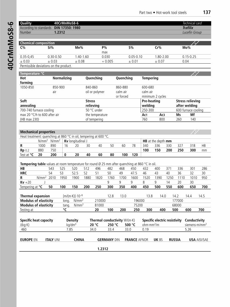
Quality 40CrMnMoS8-6 Technical cardAccording to standards DIN 17350: 1980 TrafilixNumber 1.2312 Lucefin Group
Chemical compositionC% Si% Mn% P% S% Cr% Mo%
max0.35-0,45 0.30-0.50 1.40-1.60 0.030 0.05-0.10 1.80-2.00 0.15-0.25± 0.03 ± 0.03 ± 0.08 + 0.005 ± 0.01 ± 0.07 0.04Permissible deviations on the product.
Temperature °CHot Normalizing Quenching Quenching Temperingforming1050-850 850-900 840-860 860-880 600-680
air oil or polymer calm air calm airor forced minimum 2 cycles
Soft Stress Pre-heating Stress relievingannealing relieving welding after welding700-740 furnace cooling 50 °C under 250-300 600 furnace coolingmax 20 °C/h to 600 after air the temperature Ac1 Ac3 Ms Mf(HB max 230) of tempering 760 800 260 140
Mechanical propertiesHeat treatment: quenching at 860 °C in oil, tempering at 600 °C.
N/mm2 N/mm2 Kv longitudinal J HB at the depth mmR 1000 890 16 20 30 40 50 60 78 340 336 330 327 318 HBRp 0.2 880 750 100 150 200 250 300 mmTest at °C 20 200 0 20 40 60 80 100 120
Tempering table values at room temperature for round Ø 25 mm after quenching at 860 °C in oil.HB 543 525 520 512 496 482 468 450 432 400 371 336 301 286HRC 54 53 52.5 52 51 50 49 47.5 46 43 40 36 32 30R N/mm2 2010 1950 1900 1880 1820 1760 1700 1600 1520 1390 1250 1110 1010 950Kv +20 J 9 9 9 8 9 14 20 30 Tempering at °C 50 100 150 200 250 300 350 400 450 500 550 600 650 700
Thermal expansion [m/(m·K)]·10–6 12.8 13.0 13.8 14.0 14.2 14.4 14.5Modulus of elasticity long. N/mm2 210000 196000 177000 Modulus of elasticity tang. N/mm2 81000 75200 68000Testing at °C 20 100 200 250 300 400 500 600 700
EUROPE EN ITALY UNI CHINA GERMANY DIN FRANCE AFNOR UK BS RUSSIA USA AISI/SAE
1.2312
Specific heat capacity Density Thermal conductivity W/(m·K) Specific electric resistivity ConductivityJ(kg·K) kg/dm3 20 °C 250 °C 500 °C ohm·mm2/m siemens·m/mm2
460 7.85 34.0 33.4 33.0 0.19 5.26
40Cr
MnM
oS8-
6Part two • Hot-work tool steels 137
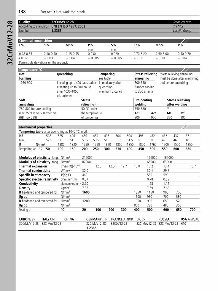
Quality 32CrMoV12-28 Technical cardAccording to standards UNI EN ISO 4957: 2002 TrafilixNumber 1.2365 Lucefin Group
Chemical compositionC% Si% Mn% P% S% Cr% Mo% V%
max max0.28-0.35 0.10-0.40 0.15-0.45 0.030 0.020 2.70-3.20 2.50-3.00 0.40-0.70± 0.02 ± 0.03 ± 0.04 + 0.005 + 0.005 ± 0.10 ± 0.10 ± 0.04Permissible deviations on the product.
Temperature °CHot Quenching Tempering Stress relieving Stress relieving annealingforming see table annealing must be done after machining 1050-900 I heating up to 400 pause, after immediately after 600-650 and before quenching
II heating up to 800 pause quenching furnace coolingafter 1030-1050 minimum 2 cycles to 350 after, airoil, polymer
Soft Stress Pre-heating Stress relievingannealing relieving1) welding after welding780-800 furnace cooling 50 °C under 350-380 1)
max 25 °C/h to 600 after air the temperature Ac1 Ac3 Ms Mf(HB max 229) of tempering 800 900 320 100
Mechanical propertiesTempering table after quenching at 1040 °C in oil.HB 518 525 496 489 489 496 504 504 496 482 432 432 371HRC 52.5 52 51 50.5 50.5 51 51.5 51.5 51 50 49 46 40R N/mm2 1880 1820 1790 1790 1820 1850 1850 1820 1760 1700 1520 1250Tempering at °C 50 100 150 200 250 300 350 400 450 500 550 600 650
Modulus of elasticity long. N/mm2 215000 176000 165000Modulus of elasticity tang. N/mm2 82000 68000 63000Thermal expansion [m/(m·K)]·10–6 12.0 12.5 12.7 13.0 13.2 13.4 13.7Thermal conductivity W/(m·K) 30.0 30.1 29.7Specific heat capacity J/(Kg·K) 460 550 590Specific electric resistivity ohm·mm2/m 0.37 0.78 0.89Conductivity siemens·m/mm2 2.70 1.28 1.12Density kg/dm3 7.88 7.69 7.65R hardened and tempered for N/mm2 1600 1350 1150 900 700Rp 0.2 N/mm2 1100 950 700 580R hardened and tempered for N/mm2 1200 1050 900 650 520Rp 0.2 N/mm2 850 730 480 360Testing at °C 20 100 200 300 400 500 600 650 700
EUROPE EN ITALY UNI CHINA GERMANY DIN FRANCE AFNOR UK BS RUSSIA USA AISI/SAE 32CrMoV12-28 32CrMoV12-28 32CrMoV12-28 32CDV12-28 32CrMoV12-28 32CrMoV12-28 H10
1.2365
32Cr
MoV
12-2
8138 Part two • Hot-work tool steels
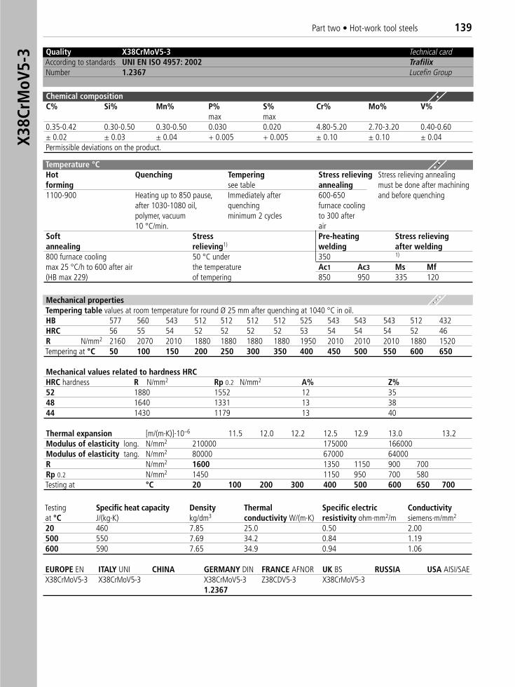
Quality X38CrMoV5-3 Technical cardAccording to standards UNI EN ISO 4957: 2002 TrafilixNumber 1.2367 Lucefin Group
Chemical compositionC% Si% Mn% P% S% Cr% Mo% V%
max max0.35-0.42 0.30-0.50 0.30-0.50 0.030 0.020 4.80-5.20 2.70-3.20 0.40-0.60± 0.02 ± 0.03 ± 0.04 + 0.005 + 0.005 ± 0.10 ± 0.10 ± 0.04Permissible deviations on the product.
Temperature °CHot Quenching Tempering Stress relieving Stress relieving annealingforming see table annealing must be done after machining 1100-900 Heating up to 850 pause, Immediately after 600-650 and before quenching
after 1030-1080 oil, quenching furnace coolingpolymer, vacuum minimum 2 cycles to 300 after10 °C/min. air
Soft Stress Pre-heating Stress relievingannealing relieving1) welding after welding800 furnace cooling 50 °C under 350 1)
max 25 °C/h to 600 after air the temperature Ac1 Ac3 Ms Mf(HB max 229) of tempering 850 950 335 120
Mechanical propertiesTempering table values at room temperature for round Ø 25 mm after quenching at 1040 °C in oil.HB 577 560 543 512 512 512 512 525 543 543 543 512 432HRC 56 55 54 52 52 52 52 53 54 54 54 52 46R N/mm2 2160 2070 2010 1880 1880 1880 1880 1950 2010 2010 2010 1880 1520Tempering at °C 50 100 150 200 250 300 350 400 450 500 550 600 650
Mechanical values related to hardness HRCHRC hardness R N/mm2 Rp 0.2 N/mm2 A% Z%52 1880 1552 12 3548 1640 1331 13 38 44 1430 1179 13 40
Thermal expansion [m/(m·K)]·10–6 11.5 12.0 12.2 12.5 12.9 13.0 13.2Modulus of elasticity long. N/mm2 210000 175000 166000Modulus of elasticity tang. N/mm2 80000 67000 64000R N/mm2 1600 1350 1150 900 700Rp 0.2 N/mm2 1450 1150 950 700 580Testing at °C 20 100 200 300 400 500 600 650 700
EUROPE EN ITALY UNI CHINA GERMANY DIN FRANCE AFNOR UK BS RUSSIA USA AISI/SAE X38CrMoV5-3 X38CrMoV5-3 X38CrMoV5-3 Z38CDV5-3 X38CrMoV5-3
1.2367
Testing Specific heat capacity Density Thermal Specific electric Conductivityat °C J/(kg·K) kg/dm3 conductivity W/(m·K) resistivity ohm·mm2/m siemens·m/mm2
20 460 7.85 25.0 0.50 2.00500 550 7.69 34.2 0.84 1.19600 590 7.65 34.9 0.94 1.06
X38C
rMoV
5-3
Part two • Hot-work tool steels 139
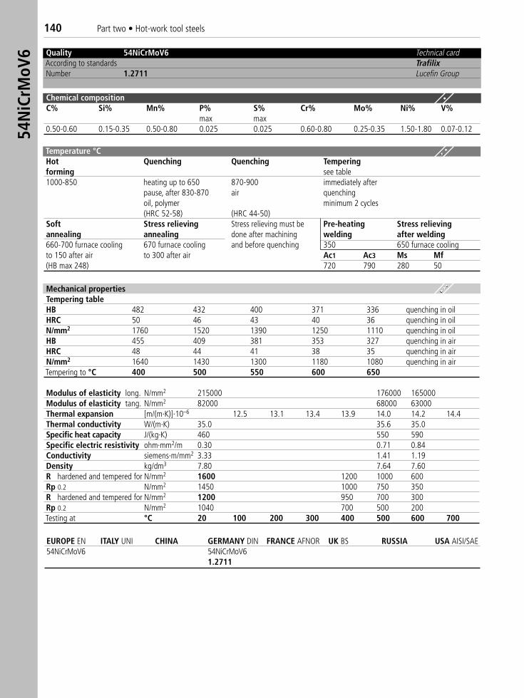
Quality 54NiCrMoV6 Technical cardAccording to standards TrafilixNumber 1.2711 Lucefin Group
Chemical compositionC% Si% Mn% P% S% Cr% Mo% Ni% V%
max max0.50-0.60 0.15-0.35 0.50-0.80 0.025 0.025 0.60-0.80 0.25-0.35 1.50-1.80 0.07-0.12
Temperature °CHot Quenching Quenching Temperingforming see table1000-850 heating up to 650 870-900 immediately after
pause, after 830-870 air quenchingoil, polymer minimum 2 cycles(HRC 52-58) (HRC 44-50)
Soft Stress relieving Stress relieving must be Pre-heating Stress relievingannealing annealing done after machining welding after welding660-700 furnace cooling 670 furnace cooling and before quenching 350 650 furnace coolingto 150 after air to 300 after air Ac1 Ac3 Ms Mf(HB max 248) 720 790 280 50
Mechanical propertiesTempering tableHB 482 432 400 371 336 quenching in oilHRC 50 46 43 40 36 quenching in oilN/mm2 1760 1520 1390 1250 1110 quenching in oilHB 455 409 381 353 327 quenching in airHRC 48 44 41 38 35 quenching in airN/mm2 1640 1430 1300 1180 1080 quenching in airTempering to °C 400 500 550 600 650
Modulus of elasticity long. N/mm2 215000 176000 165000Modulus of elasticity tang. N/mm2 82000 68000 63000Thermal expansion [m/(m·K)]·10–6 12.5 13.1 13.4 13.9 14.0 14.2 14.4Thermal conductivity W/(m·K) 35.0 35.6 35.0Specific heat capacity J/(kg·K) 460 550 590Specific electric resistivity ohm·mm2/m 0.30 0.71 0.84Conductivity siemens·m/mm2 3.33 1.41 1.19Density kg/dm3 7.80 7.64 7.60R hardened and tempered for N/mm2 1600 1200 1000 600Rp 0.2 N/mm2 1450 1000 750 350R hardened and tempered for N/mm2 1200 950 700 300Rp 0.2 N/mm2 1040 700 500 200Testing at °C 20 100 200 300 400 500 600 700
EUROPE EN ITALY UNI CHINA GERMANY DIN FRANCE AFNOR UK BS RUSSIA USA AISI/SAE 54NiCrMoV6 54NiCrMoV6
1.2711
54N
iCrM
oV6
140 Part two • Hot-work tool steels
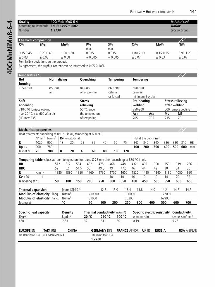
Quality 40CrMnNiMo8-6-4 Technical cardAccording to standards EN ISO 4957: 2002 TrafilixNumber 1.2738 Lucefin Group
Chemical compositionC% Si% Mn% P% S% Cr% Mo% Ni%
max max0.35-0.45 0.20-0.40 1.30-1.60 0.035 0.035 1.80-2.10 0.15-0.25 0.90-1.20± 0.03 ± 0.03 ± 0.08 + 0.005 + 0.005 ± 0.07 ± 0.03 ± 0.07Permissible deviations on the product.By agreement, the sulphur content can be increased to 0.05-0.10%.
Temperature °CHot Normalizing Quenching Tempering Temperingforming1050-850 850-900 840-860 860-880 500-600
air oil or polymer calm air calm airor forced minimum 2 cycles
Soft Stress Pre-heating Stress relievingannealing relieving welding after welding710-740 furnace cooling 50 °C under 250-300 500 furnace coolingmax 20 °C/h to 600 after air the temperature Ac1 Ac3 Ms Mf(HB max 235) of tempering 705 795 215 20
Mechanical propertiesHeat treatment: quenching at 850 °C in oil, tempering at 600 °C.
N/mm2 N/mm2 Kv longitudinal J HB at the depth mmR 1020 900 18 20 25 35 40 50 75 340 340 340 336 330 310 HBRp 0.2 900 760 100 200 300 400 500 600 mmTest at °C 20 200 0 20 40 60 80 100 120
Tempering table values at room temperature for round Ø 25 mm after quenching at 860 °C in oil.HB 512 512 504 482 475 468 448 432 409 390 353 319 286HRC 52 52 51.5 50 49,5 49 47,5 46 44 42 38 34 30R N/mm2 1880 1880 1850 1760 1730 1700 1600 1520 1430 1340 1180 1050 950 Kv +20 J 10 10 10 10 10 14 20 32Tempering at °C 50 100 150 200 250 300 350 400 450 500 550 600 650
Thermal expansion [m/(m·K)]·10–6 12.8 13.0 13.4 13.8 14.0 14.2 14.2 14.5Modulus of elasticity long. N/mm2 210000 196000 177000Modulus of elasticity tang. N/mm2 81000 75200 67900Testing at °C 20 100 200 250 300 400 500 600 700
EUROPE EN ITALY UNI CHINA GERMANY DIN FRANCE AFNOR UK BS RUSSIA USA AISI/SAE 40CrMnNiMo8-6-4 40CrMnNiMo8-6-4 40CrMnNiMo8-6-4
1.2738
Specific heat capacity Density Thermal conductivity W/(m·K) Specific electric resistivity ConductivityJ(kg·K) kg/dm3 20 °C 250 °C 500 °C ohm·mm2/m siemens·m/mm2
460 7.83 32 31.1 30 0.19 5.26
40Cr
MnN
iMo8
-6-4
Part two • Hot-work tool steels 141
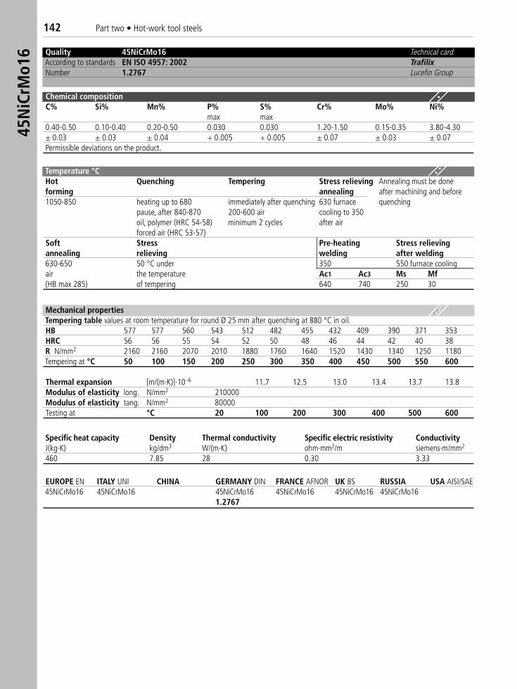
Quality 45NiCrMo16 Technical cardAccording to standards EN ISO 4957: 2002 TrafilixNumber 1.2767 Lucefin Group
Chemical compositionC% Si% Mn% P% S% Cr% Mo% Ni%
max max0.40-0.50 0.10-0.40 0.20-0.50 0.030 0.030 1.20-1.50 0.15-0.35 3.80-4.30± 0.03 ± 0.03 ± 0.04 + 0.005 + 0.005 ± 0.07 ± 0.03 ± 0.07Permissible deviations on the product.
Temperature °CHot Quenching Tempering Stress relieving Annealing must be doneforming annealing after machining and before1050-850 heating up to 680 immediately after quenching 630 furnace quenching
pause, after 840-870 200-600 air cooling to 350oil, polymer (HRC 54-58) minimum 2 cycles after airforced air (HRC 53-57)
Soft Stress Pre-heating Stress relievingannealing relieving welding after welding630-650 50 °C under 350 550 furnace coolingair the temperature Ac1 Ac3 Ms Mf(HB max 285) of tempering 640 740 250 30
Mechanical propertiesTempering table values at room temperature for round Ø 25 mm after quenching at 880 °C in oil.HB 577 577 560 543 512 482 455 432 409 390 371 353HRC 56 56 55 54 52 50 48 46 44 42 40 38R N/mm2 2160 2160 2070 2010 1880 1760 1640 1520 1430 1340 1250 1180Tempering at °C 50 100 150 200 250 300 350 400 450 500 550 600
Thermal expansion [m/(m·K)]·10–6 11.7 12.5 13.0 13.4 13.7 13.8 Modulus of elasticity long. N/mm2 210000Modulus of elasticity tang. N/mm2 80000Testing at °C 20 100 200 300 400 500 600
EUROPE EN ITALY UNI CHINA GERMANY DIN FRANCE AFNOR UK BS RUSSIA USA AISI/SAE 45NiCrMo16 45NiCrMo16 45NiCrMo16 45NiCrMo16 45NiCrMo16 45NiCrMo16
1.2767
Specific heat capacity Density Thermal conductivity Specific electric resistivity ConductivityJ(kg·K) kg/dm3 W/(m·K) ohm·mm2/m siemens·m/mm2
460 7.85 28 0.30 3.33
45N
iCrM
o16
142 Part two • Hot-work tool steels
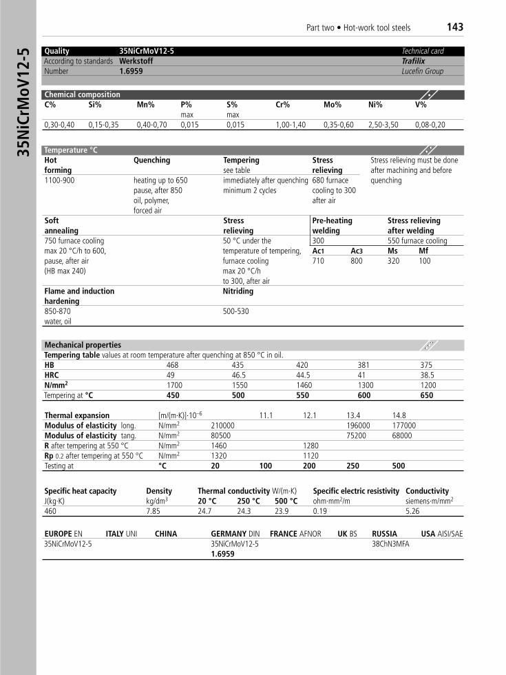
Quality 35NiCrMoV12-5 Technical cardAccording to standards Werkstoff TrafilixNumber 1.6959 Lucefin Group
Chemical compositionC% Si% Mn% P% S% Cr% Mo% Ni% V%
max max0,30-0,40 0,15-0,35 0,40-0,70 0,015 0,015 1,00-1,40 0,35-0,60 2,50-3,50 0,08-0,20
Temperature °CHot Quenching Tempering Stress Stress relieving must be doneforming see table relieving after machining and before1100-900 heating up to 650 immediately after quenching 680 furnace quenching
pause, after 850 minimum 2 cycles cooling to 300oil, polymer, after airforced air
Soft Stress Pre-heating Stress relievingannealing relieving welding after welding750 furnace cooling 50 °C under the 300 550 furnace coolingmax 20 °C/h to 600, temperature of tempering, Ac1 Ac3 Ms Mfpause, after air furnace cooling 710 800 320 100(HB max 240) max 20 °C/h
to 300, after airFlame and induction Nitridinghardening850-870 500-530water, oil
Mechanical propertiesTempering table values at room temperature after quenching at 850 °C in oil.HB 468 435 420 381 375HRC 49 46.5 44.5 41 38.5N/mm2 1700 1550 1460 1300 1200Tempering at °C 450 500 550 600 650
Thermal expansion [m/(m·K)]·10–6 11.1 12.1 13.4 14.8 Modulus of elasticity long. N/mm2 210000 196000 177000Modulus of elasticity tang. N/mm2 80500 75200 68000R after tempering at 550 °C N/mm2 1460 1280Rp 0.2 after tempering at 550 °C N/mm2 1320 1120Testing at °C 20 100 200 250 500
EUROPE EN ITALY UNI CHINA GERMANY DIN FRANCE AFNOR UK BS RUSSIA USA AISI/SAE 35NiCrMoV12-5 35NiCrMoV12-5 38ChN3MFA
1.6959
Specific heat capacity Density Thermal conductivity W/(m·K) Specific electric resistivity ConductivityJ(kg·K) kg/dm3 20 °C 250 °C 500 °C ohm·mm2/m siemens·m/mm2
460 7.85 24.7 24.3 23.9 0.19 5.26
35N
iCrM
oV12
-5Part two • Hot-work tool steels 143
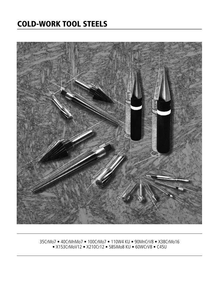
COLD-WORK TOOL STEELS
35CrMo7 • 40CrMnMo7 • 100CrMo7 • 110W4 KU • 90MnCrV8 • X38CrMo16• X153CrMoV12 • X210Cr12 • 58SiMo8 KU • 60WCrV8 • C45U
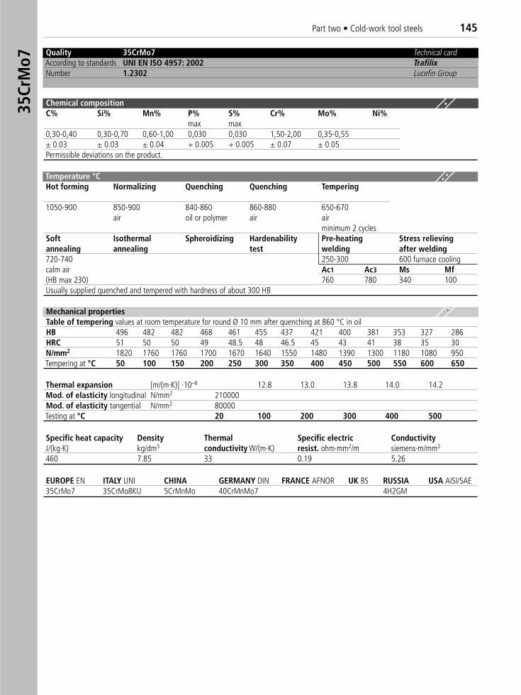
Part two • Cold-work tool steels 14535
CrM
o7
Quality 35CrMo7 Technical cardAccording to standards UNI EN ISO 4957: 2002 TrafilixNumber 1.2302 Lucefin Group
Chemical compositionC% Si% Mn% P% S% Cr% Mo% Ni%
max max0,30-0,40 0,30-0,70 0,60-1,00 0,030 0,030 1,50-2,00 0,35-0,55± 0.03 ± 0.03 ± 0.04 + 0.005 + 0.005 ± 0.07 ± 0.05Permissible deviations on the product.
Thermal expansion [m/(m·K)] ·10–6 12.8 13.0 13.8 14.0 14.2Mod. of elasticity longitudinal N/mm2 210000Mod. of elasticity tangential N/mm2 80000Testing at °C 20 100 200 300 400 500
EUROPE EN ITALY UNI CHINA GERMANY DIN FRANCE AFNOR UK BS RUSSIA USA AISI/SAE 35CrMo7 35CrMo8KU 5CrMnMo 40CrMnMo7 4H2GM
Mechanical propertiesTable of tempering values at room temperature for round Ø 10 mm after quenching at 860 °C in oilHB 496 482 482 468 461 455 437 421 400 381 353 327 286HRC 51 50 50 49 48.5 48 46.5 45 43 41 38 35 30N/mm2 1820 1760 1760 1700 1670 1640 1550 1480 1390 1300 1180 1080 950Tempering at °C 50 100 150 200 250 300 350 400 450 500 550 600 650
Specific heat capacity Density Thermal Specific electric ConductivityJ/(kg·K) kg/dm3 conductivity W/(m·K) resist. ohm·mm2/m siemens·m/mm2
460 7.85 33 0.19 5.26
Temperature °C Hot forming Normalizing Quenching Quenching Tempering
1050-900 850-900 840-860 860-880 650-670air oil or polymer air air
minimum 2 cyclesSoft Isothermal Spheroidizing Hardenability Pre-heating Stress relievingannealing annealing test welding after welding720-740 250-300 600 furnace coolingcalm air Ac1 Ac3 Ms Mf(HB max 230) 760 780 340 100Usually supplied quenched and tempered with hardness of about 300 HB
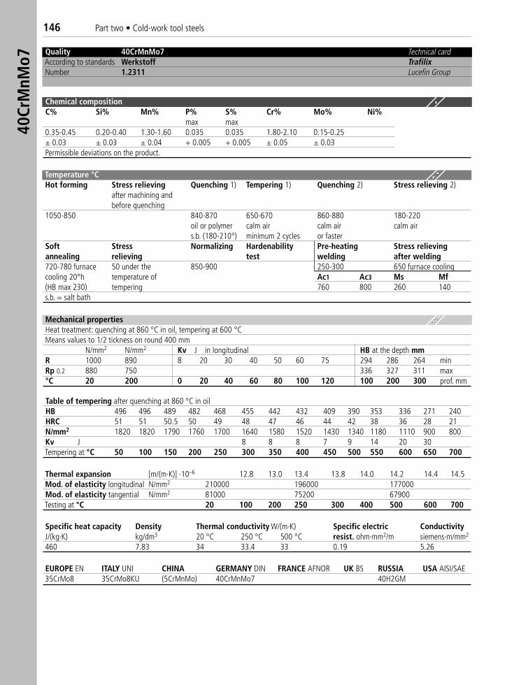
146 Part two • Cold-work tool steels40
CrM
nMo7
Quality 40CrMnMo7 Technical cardAccording to standards Werkstoff TrafilixNumber 1.2311 Lucefin Group
Chemical compositionC% Si% Mn% P% S% Cr% Mo% Ni%
max max0.35-0.45 0.20-0.40 1.30-1.60 0.035 0.035 1.80-2.10 0.15-0.25± 0.03 ± 0.03 ± 0.04 + 0.005 + 0.005 ± 0.05 ± 0.03Permissible deviations on the product.
Temperature °C Hot forming Stress relieving Quenching 1) Tempering 1) Quenching 2) Stress relieving 2)
after machining andbefore quenching
1050-850 840-870 650-670 860-880 180-220oil or polymer calm air calm air calm airs.b. (180-210°) minimum 2 cycles or faster
Soft Stress Normalizing Hardenability Pre-heating Stress relievingannealing relieving test welding after welding720-780 furnace 50 under the 850-900 250-300 650 furnace coolingcooling 20°h temperature of Ac1 Ac3 Ms Mf(HB max 230) tempering 760 800 260 140 s.b. = salt bath
Mechanical propertiesHeat treatment: quenching at 860 °C in oil, tempering at 600 °CMeans values to 1/2 tickness on round 400 mm
N/mm2 N/mm2 Kv J in longitudinal HB at the depth mmR 1000 890 8 20 30 40 50 60 75 294 286 264 minRp 0.2 880 750 336 327 311 max°C 20 200 0 20 40 60 80 100 120 100 200 300 prof. mm
Table of tempering after quenching at 860 °C in oilHB 496 496 489 482 468 455 442 432 409 390 353 336 271 240HRC 51 51 50.5 50 49 48 47 46 44 42 38 36 28 21N/mm2 1820 1820 1790 1760 1700 1640 1580 1520 1430 1340 1180 1110 900 800Kv J 8 8 8 7 9 14 20 30Tempering at °C 50 100 150 200 250 300 350 400 450 500 550 600 650 700
Thermal expansion [m/(m·K)] ·10–6 12.8 13.0 13.4 13.8 14.0 14.2 14.4 14.5Mod. of elasticity longitudinal N/mm2 210000 196000 177000Mod. of elasticity tangential N/mm2 81000 75200 67900Testing at °C 20 100 200 250 300 400 500 600 700
EUROPE EN ITALY UNI CHINA GERMANY DIN FRANCE AFNOR UK BS RUSSIA USA AISI/SAE 35CrMo8 35CrMo8KU (5CrMnMo) 40CrMnMo7 40H2GM
Specific heat capacity Density Thermal conductivity W/(m·K) Specific electric ConductivityJ/(kg·K) kg/dm3 20 °C 250 °C 500 °C resist. ohm·mm2/m siemens·m/mm2
460 7.83 34 33.4 33 0.19 5.26
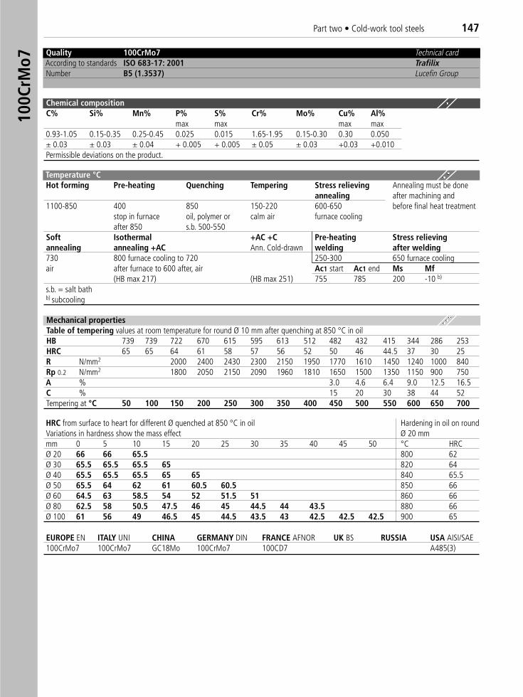
Part two • Cold-work tool steels 14710
0CrM
o7
Quality 100CrMo7 Technical cardAccording to standards ISO 683-17: 2001 TrafilixNumber B5 (1.3537) Lucefin Group
Chemical compositionC% Si% Mn% P% S% Cr% Mo% Cu% Al%
max max max max0.93-1.05 0.15-0.35 0.25-0.45 0.025 0.015 1.65-1.95 0.15-0.30 0.30 0.050± 0.03 ± 0.03 ± 0.04 + 0.005 + 0.005 ± 0.05 ± 0.03 +0.03 +0.010Permissible deviations on the product.
Temperature °C Hot forming Pre-heating Quenching Tempering Stress relieving Annealing must be done
annealing after machining and1100-850 400 850 150-220 600-650 before final heat treatment
stop in furnace oil, polymer or calm air furnace coolingafter 850 s.b. 500-550
Soft Isothermal +AC +C Pre-heating Stress relievingannealing annealing +AC Ann. Cold-drawn welding after welding730 800 furnace cooling to 720 250-300 650 furnace coolingair after furnace to 600 after, air Ac1 start Ac1 end Ms Mf
(HB max 217) (HB max 251) 755 785 200 -10 b)
s.b. = salt bathb) subcooling
Mechanical propertiesTable of tempering values at room temperature for round Ø 10 mm after quenching at 850 °C in oilHB 739 739 722 670 615 595 613 512 482 432 415 344 286 253HRC 65 65 64 61 58 57 56 52 50 46 44.5 37 30 25R N/mm2 2000 2400 2430 2300 2150 1950 1770 1610 1450 1240 1000 840Rp 0.2 N/mm2 1800 2050 2150 2090 1960 1810 1650 1500 1350 1150 900 750A % 3.0 4.6 6.4 9.0 12.5 16.5C % 15 20 30 38 44 52Tempering at °C 50 100 150 200 250 300 350 400 450 500 550 600 650 700
HRC from surface to heart for different Ø quenched at 850 °C in oil Hardening in oil on roundVariations in hardness show the mass effect Ø 20 mmmm 0 5 10 15 20 25 30 35 40 45 50 °C HRCØ 20 66 66 65.5 800 62Ø 30 65.5 65.5 65.5 65 820 64Ø 40 65.5 65.5 65.5 65 65 840 65.5Ø 50 65.5 64 62 61 60.5 60.5 850 66Ø 60 64.5 63 58.5 54 52 51.5 51 860 66Ø 80 62.5 58 50.5 47.5 46 45 44.5 44 43.5 880 66Ø 100 61 56 49 46.5 45 44.5 43.5 43 42.5 42.5 42.5 900 65
EUROPE EN ITALY UNI CHINA GERMANY DIN FRANCE AFNOR UK BS RUSSIA USA AISI/SAE 100CrMo7 100CrMo7 GC18Mo 100CrMo7 100CD7 A485(3)
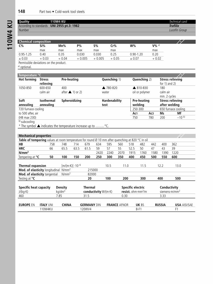
148 Part two • Cold-work tool steels11
0W4
KU
Quality 110W4 KU Technical cardAccording to standards UNI 2955 pt.3: 1982 TrafilixNumber Lucefin Group
Chemical compositionC% Si% Mn% P% S% Cr% W% V% a)
max max max max max max0.95-1.25 0.40 0.35 0.030 0.030 0.25 0.90-1.20 0.20± 0.03 + 0.03 + 0.04 + 0.005 + 0.005 + 0.05 ± 0.07 + 0.02Permissible deviations on the product.a) optional.
Thermal expansion [m/(m·K)] ·10–6 10.5 11.0 11.5 12.2 13.0Mod. of elasticity longitudinal N/mm2 215000Mod. of elasticity tangential N/mm2 82000Testing at °C 20 100 200 300 400 500
EUROPE EN ITALY UNI CHINA GERMANY DIN FRANCE AFNOR UK BS RUSSIA USA AISI/SAE 110W4KU 120WV4 B-F1 F1
Mechanical propertiesTable of tempering values at room temperature for round Ø 10 mm after quenching at 820 °C in oilHB 758 748 714 679 634 595 560 518 482 442 400 362HRC 66 65.5 63.5 61.5 59 57 55 52.5 50 47 43 39N/mm2 2420 2240 2070 1915 1760 1580 1390 1220Tempering at °C 50 100 150 200 250 300 350 400 450 500 550 600
Specific heat capacity Density Thermal Specific electric ConductivityJ/(kg·K) kg/dm3 conductivity W/(m·K) resist. ohm·mm2/m siemens·m/mm2
460 7.85 31.5 0.30 3.33
Temperature °C Hot forming Stress Pre-heating Quenching 1) Quenching 2) Stress relieving
relieving for 1) and 2)1050-850 600-650 400 ▲ 780-820 ▲ 810-830 180
calm air after ▲ 1) or 2) water oil or polymer calm airmin. 2 cycles
Soft Isothermal Spheroidizing Hardenability Pre-heating Stress relievingannealing annealing test welding after welding720 furnace cooling 250-300 650 furnace coolingto 500 after, air Ac1 Ac3 Ms Mf(HB max 230) 750 780 200 –10 b)
b) subcooling* The symbol ▲ indicates the temperature increase up to ……. °C.
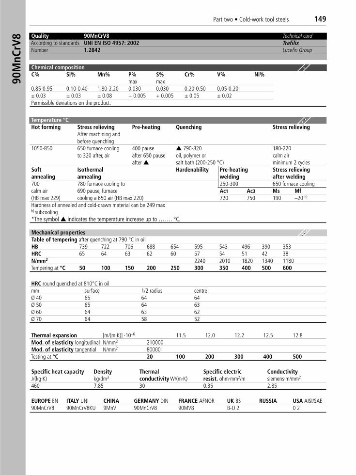
Part two • Cold-work tool steels 14990
MnC
rV8 Quality 90MnCrV8 Technical card
According to standards UNI EN ISO 4957: 2002 TrafilixNumber 1.2842 Lucefin Group
Chemical compositionC% Si% Mn% P% S% Cr% V% Ni%
max max0.85-0.95 0.10-0.40 1.80-2.20 0.030 0.030 0.20-0.50 0.05-0.20± 0.03 ± 0.03 ± 0.08 + 0.005 + 0.005 ± 0.05 ± 0.02Permissible deviations on the product.
Temperature °C Hot forming Stress relieving Pre-heating Quenching Stress relieving
After machining andbefore quenching
1050-850 650 furnace cooling 400 pause ▲ 790-820 180-220to 320 after, air after 650 pause oil, polymer or calm air
after ▲ salt bath (200-250 °C) minimum 2 cyclesSoft Isothermal Hardenability Pre-heating Stress relievingannealing annealing welding after welding700 780 furnace cooling to 250-300 650 furnace coolingcalm air 690 pause, furnace Ac1 Ac3 Ms Mf(HB max 229) cooling a 650 air (HB max 220) 720 750 190 –20 b)
Hardness of annealed and cold-drawn material can be 249 maxb) subcooling*The symbol ▲ indicates the temperature increase up to ……. °C.
HRC round quenched at 810°C in oilmm surface 1/2 radius centreØ 40 65 64 64Ø 50 65 64 63Ø 60 64 63 62Ø 70 64 58 52
Thermal expansion [m/(m·K)] ·10–6 11.5 12.0 12.2 12.5 12.8Mod. of elasticity longitudinal N/mm2 210000Mod. of elasticity tangential N/mm2 80000Testing at °C 20 100 200 300 400 500
EUROPE EN ITALY UNI CHINA GERMANY DIN FRANCE AFNOR UK BS RUSSIA USA AISI/SAE 90MnCrV8 90MnCrV8KU 9MnV 90MnCrV8 90MV8 B-O 2 0 2
Specific heat capacity Density Thermal Specific electric ConductivityJ/(kg·K) kg/dm3 conductivity W/(m·K) resist. ohm·mm2/m siemens·m/mm2
460 7.85 30 0.35 2.85
Mechanical propertiesTable of tempering after quenching at 790 °C in oilHB 739 722 706 688 654 595 543 496 390 353HRC 65 64 63 62 60 57 54 51 42 38N/mm2 2240 2010 1820 1340 1180Tempering at °C 50 100 150 200 250 300 350 400 500 600
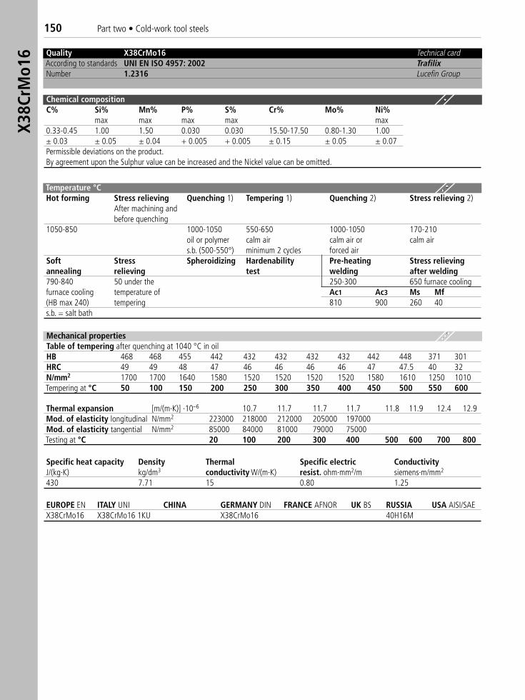
150 Part two • Cold-work tool steelsX3
8CrM
o16 Quality X38CrMo16 Technical card
According to standards UNI EN ISO 4957: 2002 TrafilixNumber 1.2316 Lucefin Group
Chemical compositionC% Si% Mn% P% S% Cr% Mo% Ni%
max max max max max0.33-0.45 1.00 1.50 0.030 0.030 15.50-17.50 0.80-1.30 1.00± 0.03 ± 0.05 ± 0.04 + 0.005 + 0.005 ± 0.15 ± 0.05 ± 0.07Permissible deviations on the product.By agreement upon the Sulphur value can be increased and the Nickel value can be omitted.
Temperature °C Hot forming Stress relieving Quenching 1) Tempering 1) Quenching 2) Stress relieving 2)
After machining andbefore quenching
1050-850 1000-1050 550-650 1000-1050 170-210oil or polymer calm air calm air or calm airs.b. (500-550°) minimum 2 cycles forced air
Soft Stress Spheroidizing Hardenability Pre-heating Stress relievingannealing relieving test welding after welding790-840 50 under the 250-300 650 furnace coolingfurnace cooling temperature of Ac1 Ac3 Ms Mf(HB max 240) tempering 810 900 260 40s.b. = salt bath
Mechanical propertiesTable of tempering after quenching at 1040 °C in oil HB 468 468 455 442 432 432 432 432 442 448 371 301HRC 49 49 48 47 46 46 46 46 47 47.5 40 32N/mm2 1700 1700 1640 1580 1520 1520 1520 1520 1580 1610 1250 1010Tempering at °C 50 100 150 200 250 300 350 400 450 500 550 600
Thermal expansion [m/(m·K)] ·10–6 10.7 11.7 11.7 11.7 11.8 11.9 12.4 12.9Mod. of elasticity longitudinal N/mm2 223000 218000 212000 205000 197000Mod. of elasticity tangential N/mm2 85000 84000 81000 79000 75000Testing at °C 20 100 200 300 400 500 600 700 800
EUROPE EN ITALY UNI CHINA GERMANY DIN FRANCE AFNOR UK BS RUSSIA USA AISI/SAE X38CrMo16 X38CrMo16 1KU X38CrMo16 40H16M
Specific heat capacity Density Thermal Specific electric ConductivityJ/(kg·K) kg/dm3 conductivity W/(m·K) resist. ohm·mm2/m siemens·m/mm2
430 7.71 15 0.80 1.25
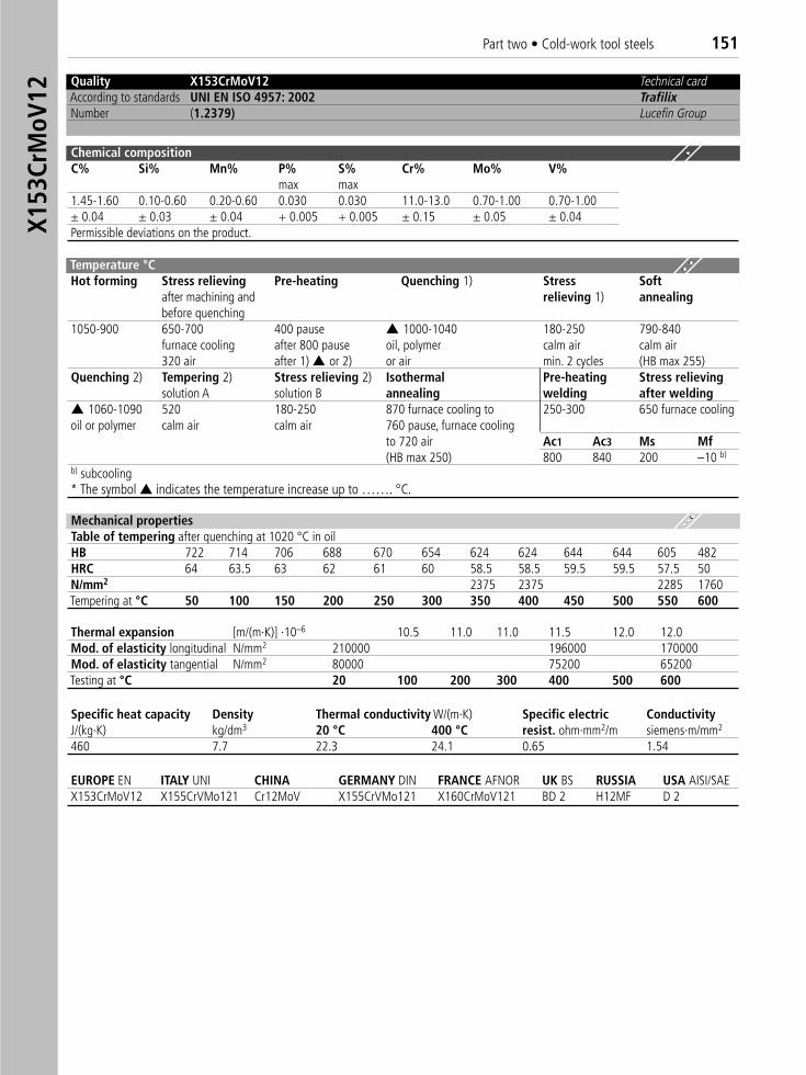
Part two • Cold-work tool steels 151X1
53Cr
MoV
12
Quality X153CrMoV12 Technical cardAccording to standards UNI EN ISO 4957: 2002 TrafilixNumber (1.2379) Lucefin Group
Chemical compositionC% Si% Mn% P% S% Cr% Mo% V%
max max1.45-1.60 0.10-0.60 0.20-0.60 0.030 0.030 11.0-13.0 0.70-1.00 0.70-1.00± 0.04 ± 0.03 ± 0.04 + 0.005 + 0.005 ± 0.15 ± 0.05 ± 0.04Permissible deviations on the product.
Mechanical propertiesTable of tempering after quenching at 1020 °C in oilHB 722 714 706 688 670 654 624 624 644 644 605 482HRC 64 63.5 63 62 61 60 58.5 58.5 59.5 59.5 57.5 50N/mm2 2375 2375 2285 1760Tempering at °C 50 100 150 200 250 300 350 400 450 500 550 600
Thermal expansion [m/(m·K)] ·10–6 10.5 11.0 11.0 11.5 12.0 12.0Mod. of elasticity longitudinal N/mm2 210000 196000 170000Mod. of elasticity tangential N/mm2 80000 75200 65200Testing at °C 20 100 200 300 400 500 600
EUROPE EN ITALY UNI CHINA GERMANY DIN FRANCE AFNOR UK BS RUSSIA USA AISI/SAEX153CrMoV12 X155CrVMo121 Cr12MoV X155CrVMo121 X160CrMoV121 BD 2 H12MF D 2
Specific heat capacity Density Thermal conductivity W/(m·K) Specific electric ConductivityJ/(kg·K) kg/dm3 20 °C 400 °C resist. ohm·mm2/m siemens·m/mm2
460 7.7 22.3 24.1 0.65 1.54
Temperature °C Hot forming Stress relieving Pre-heating Quenching 1) Stress Soft
after machining and relieving 1) annealingbefore quenching
1050-900 650-700 400 pause ▲ 1000-1040 180-250 790-840furnace cooling after 800 pause oil, polymer calm air calm air320 air after 1) ▲ or 2) or air min. 2 cycles (HB max 255)
Quenching 2) Tempering 2) Stress relieving 2) Isothermal Pre-heating Stress relievingsolution A solution B annealing welding after welding
▲ 1060-1090 520 180-250 870 furnace cooling to 250-300 650 furnace coolingoil or polymer calm air calm air 760 pause, furnace cooling
to 720 air Ac1 Ac3 Ms Mf(HB max 250) 800 840 200 –10 b)
b) subcooling* The symbol ▲ indicates the temperature increase up to ……. °C.
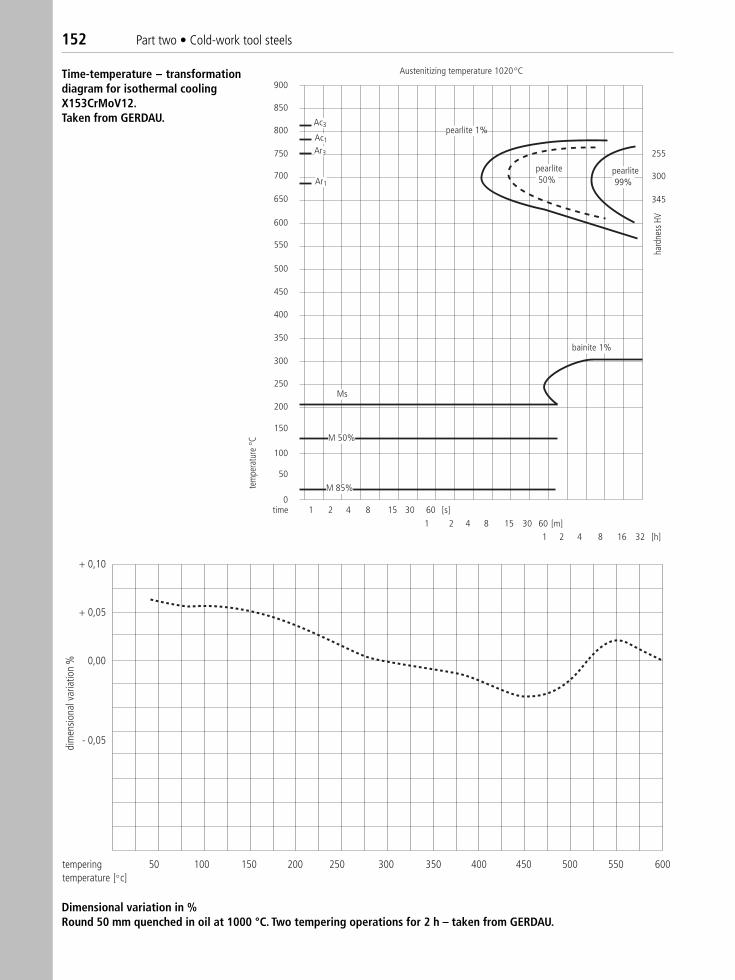
152 Part two • Cold-work tool steels
Austenitizing temperature 1020 C
pearlite 1%
pearlite99%
bainite 1%
Ms
M 50%
M 85%
Ac3
Ac1
900
850
800
750
700
650
600
550
500
450
400
350
300
250
200
150
100
50
01 2 4 8 15 30 60 [s]
1 2 4 8 15 30 60 [m]1 2 4 8 16 32 [h]
time
Ar3
Ar1
pearlite50%
255
300
345
hard
ness
HV
tem
pera
ture
C
+ 0,10
+ 0,05
0,00
- 0,05
50 100 150 200 250 300 350 400 450 500 550 600temperingtemperature [ c]
dim
ensio
nal v
aria
tion
%Time-temperature – transformationdiagram for isothermal coolingX153CrMoV12.Taken from GERDAU.
Dimensional variation in %Round 50 mm quenched in oil at 1000 °C. Two tempering operations for 2 h – taken from GERDAU.
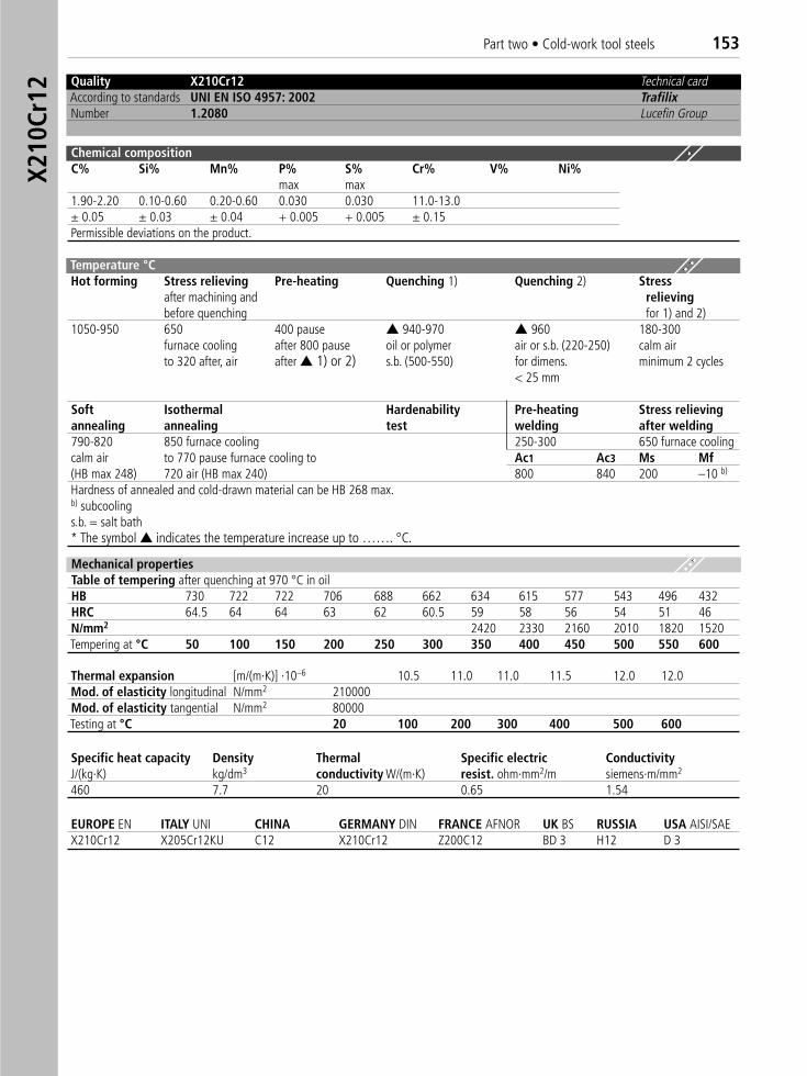
Part two • Cold-work tool steels 153X2
10Cr
12
Quality X210Cr12 Technical cardAccording to standards UNI EN ISO 4957: 2002 TrafilixNumber 1.2080 Lucefin Group
Chemical compositionC% Si% Mn% P% S% Cr% V% Ni%
max max1.90-2.20 0.10-0.60 0.20-0.60 0.030 0.030 11.0-13.0± 0.05 ± 0.03 ± 0.04 + 0.005 + 0.005 ± 0.15Permissible deviations on the product.
Mechanical propertiesTable of tempering after quenching at 970 °C in oilHB 730 722 722 706 688 662 634 615 577 543 496 432HRC 64.5 64 64 63 62 60.5 59 58 56 54 51 46N/mm2 2420 2330 2160 2010 1820 1520Tempering at °C 50 100 150 200 250 300 350 400 450 500 550 600
Thermal expansion [m/(m·K)] ·10–6 10.5 11.0 11.0 11.5 12.0 12.0Mod. of elasticity longitudinal N/mm2 210000Mod. of elasticity tangential N/mm2 80000Testing at °C 20 100 200 300 400 500 600
EUROPE EN ITALY UNI CHINA GERMANY DIN FRANCE AFNOR UK BS RUSSIA USA AISI/SAEX210Cr12 X205Cr12KU C12 X210Cr12 Z200C12 BD 3 H12 D 3
Specific heat capacity Density Thermal Specific electric ConductivityJ/(kg·K) kg/dm3 conductivity W/(m·K) resist. ohm·mm2/m siemens·m/mm2
460 7.7 20 0.65 1.54
Temperature °C Hot forming Stress relieving Pre-heating Quenching 1) Quenching 2) Stress
after machining and relievingbefore quenching for 1) and 2)
1050-950 650 400 pause ▲ 940-970 ▲ 960 180-300furnace cooling after 800 pause oil or polymer air or s.b. (220-250) calm airto 320 after, air after ▲ 1) or 2) s.b. (500-550) for dimens. minimum 2 cycles
< 25 mm
Soft Isothermal Hardenability Pre-heating Stress relievingannealing annealing test welding after welding790-820 850 furnace cooling 250-300 650 furnace coolingcalm air to 770 pause furnace cooling to Ac1 Ac3 Ms Mf(HB max 248) 720 air (HB max 240) 800 840 200 –10 b)
Hardness of annealed and cold-drawn material can be HB 268 max.b) subcoolings.b. = salt bath* The symbol ▲ indicates the temperature increase up to ……. °C.
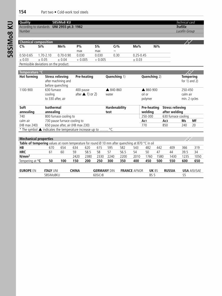
154 Part two • Cold-work tool steels58
SiM
o8 K
U Quality 58SiMo8 KU Technical cardAccording to standards UNI 2955 pt.3: 1982 TrafilixNumber Lucefin Group
Chemical compositionC% Si% Mn% P% S% Cr% Mo% Ni%
max max ~0.50-0.65 1.70-2.10 0.70-0.90 0.030 0.030 0.30 0.25-0.45± 0.03 ± 0.05 ± 0.04 + 0.005 + 0.005 ± 0.03Permissible deviations on the product.
Mechanical propertiesTable of tempering values at room temperature for round Ø 10 mm after quenching at 870 °C in oilHB 670 654 634 620 615 595 582 543 482 442 409 366 319HRC 61 60 59 58.5 58 57 56.5 54 50 47 44 39.5 34N/mm2 2420 2380 2330 2240 2200 2010 1760 1580 1430 1235 1050Tempering at °C 50 100 150 200 250 300 350 400 450 500 550 600 650
EUROPE EN ITALY UNI CHINA GERMANY DIN FRANCE AFNOR UK BS RUSSIA USA AISI/SAE58SiMo8KU 60SiCr8 BS 5 S5
Temperature °C Hot forming Stress relieving Pre-heating Quenching 1) Quenching 2) Tempering
after machining and for 1) and 2)before quenching
1100-900 630 furnace 400 pause ▲ 840-860 ▲ 860-900 250-450cooling after ▲ 1) or 2) water oil or calm airto 330 after, air polymer min. 2 cycles
Soft Isothermal Hardenability Pre-heating Stress relievingannealing annealing test welding after welding740 800 furnace cooling to 250-300 630 furnace coolingcalm air 730 pause furnace cooling to Ac1 Ac3 Ms Mf(HB max 240) 650 pause after, air (HB max 230) 770 850 240 20* The symbol ▲ indicates the temperature increase up to ……. °C.
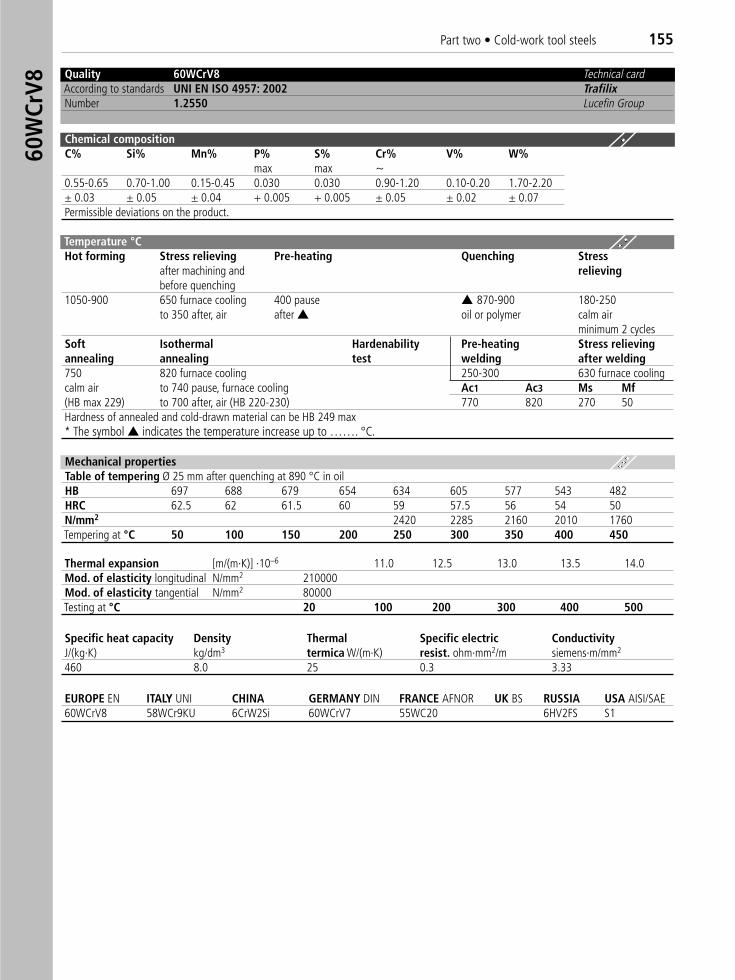
Part two • Cold-work tool steels 15560
WCr
V8
Quality 60WCrV8 Technical cardAccording to standards UNI EN ISO 4957: 2002 TrafilixNumber 1.2550 Lucefin Group
Chemical compositionC% Si% Mn% P% S% Cr% V% W%
max max ~0.55-0.65 0.70-1.00 0.15-0.45 0.030 0.030 0.90-1.20 0.10-0.20 1.70-2.20± 0.03 ± 0.05 ± 0.04 + 0.005 + 0.005 ± 0.05 ± 0.02 ± 0.07Permissible deviations on the product.
Temperature °C Hot forming Stress relieving Pre-heating Quenching Stress
after machining and relievingbefore quenching
1050-900 650 furnace cooling 400 pause ▲ 870-900 180-250 to 350 after, air after ▲ oil or polymer calm air
minimum 2 cyclesSoft Isothermal Hardenability Pre-heating Stress relievingannealing annealing test welding after welding750 820 furnace cooling 250-300 630 furnace coolingcalm air to 740 pause, furnace cooling Ac1 Ac3 Ms Mf(HB max 229) to 700 after, air (HB 220-230) 770 820 270 50Hardness of annealed and cold-drawn material can be HB 249 max* The symbol ▲ indicates the temperature increase up to ……. °C.
Mechanical propertiesTable of tempering Ø 25 mm after quenching at 890 °C in oilHB 697 688 679 654 634 605 577 543 482HRC 62.5 62 61.5 60 59 57.5 56 54 50N/mm2 2420 2285 2160 2010 1760Tempering at °C 50 100 150 200 250 300 350 400 450
Thermal expansion [m/(m·K)] ·10–6 11.0 12.5 13.0 13.5 14.0Mod. of elasticity longitudinal N/mm2 210000Mod. of elasticity tangential N/mm2 80000Testing at °C 20 100 200 300 400 500
EUROPE EN ITALY UNI CHINA GERMANY DIN FRANCE AFNOR UK BS RUSSIA USA AISI/SAE60WCrV8 58WCr9KU 6CrW2Si 60WCrV7 55WC20 6HV2FS S1
Specific heat capacity Density Thermal Specific electric ConductivityJ/(kg·K) kg/dm3 termica W/(m·K) resist. ohm·mm2/m siemens·m/mm2
460 8.0 25 0.3 3.33
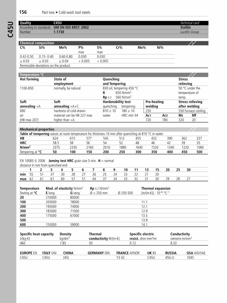
156 Part two • Cold-work tool steelsC4
5U
Quality C45U Technical cardAccording to standards UNI EN ISO 4957: 2002 TrafilixNumber 1.1730 Lucefin Group
Chemical compositionC% Si% Mn% P% S% Cr% Mo% Ni%
max max0.42-0.50 0.15- 0.40 0.60-0.80 0.030 0.030± 0.03 ± 0.03 ± 0.04 + 0.005 + 0.005Permissible deviations on the product.
Temperature °C Hot forming State of Quenching Stress
employment and Tempering relieving1100-850 normally, be natural 830 oil, tempering 450 °C 50 °C under the
R 650 N/mm2 temperature ofRp 0.2 560 N/mm2 temp.
Soft Soft Hardenability test Pre-heating Stress relievingannealing +A annealing +A+C quenching tempering welding after welding690 hardness of cold-drawn 810 ± 10 180 ± 10 250 550 furnace coolingair material can be HB 227 max water HRC min 54 Ac1 Ac3 Ms Mf(HB max 207) higher than +A 720 780 320 20
Mechanical propertiesTable of tempering values at room temperature for thickness 10 mm after quenching at 810 °C in waterHB 624 615 577 543 512 455 432 390 362 327HRC 58.5 58 56 54 52 48 46 42 39 35N/mm2 2375 2330 2160 2010 1880 1640 1520 1340 1220 1080Tempering at °C 50 100 150 200 250 300 350 400 450 500
EN 10083-3: 2006 Jominy test HRC grain size 5 min. H = normaldistance in mm from quenched end
1 2 3 4 5 6 7 8 9 10 11 13 15 20 25 30min 55 51 37 30 28 27 26 25 24 23 22 21 20max 62 61 61 60 57 51 44 37 34 33 32 31 30 29 28 27
Temperature Mod. of elasticity N/mm2 Rp 0.2 N/mm2 Thermal expansionTesting at °C E long. G tang. Ø < 250 mm Ø 250-500 [m/(m·K)] · 10–6 °C–1
20 210000 80000100 205000 78000 11.1200 195000 74000 12.1300 185000 71000 12.9400 175000 67000 13.5500 13.9600 155000 59000 14.1
Specific heat capacity Density Thermal Specific electric ConductivityJ/(kg·K) kg/dm3 conductivity W/(m·K) resist. ohm·mm2/m siemens·m/mm2
460 7.85 50 0.12 8.33
EUROPE EN ITALY UNI CHINA GERMANY DIN FRANCE AFNOR UK BS RUSSIA USA AISI/SAEC45U C45U (45) Y3 42 C45U 45G-U 1045
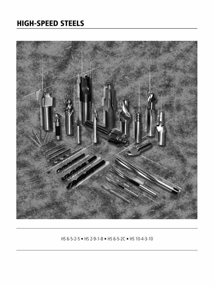
HIGH-SPEED STEELS
HS 6-5-2-5 • HS 2-9-1-8 • HS 6-5-2C • HS 10-4-3-10
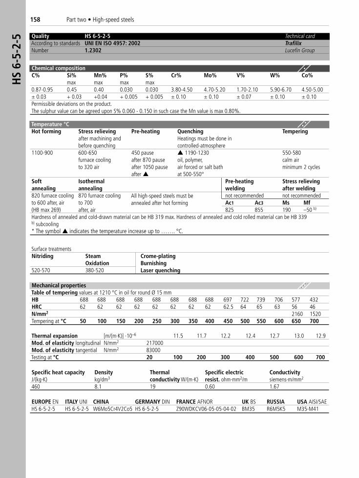
158 Part two • High-speed steelsH
S 6-
5-2-
5 Quality HS 6-5-2-5 Technical cardAccording to standards UNI EN ISO 4957: 2002 TrafilixNumber 1.2302 Lucefin Group
Chemical compositionC% Si% Mn% P% S% Cr% Mo% V% W% Co%
max max max max0.87-0.95 0.45 0.40 0.030 0.030 3.80-4.50 4.70-5.20 1.70-2.10 5.90-6.70 4.50-5.00± 0.03 + 0.03 +0.04 + 0.005 + 0.005 ± 0.10 ± 0.10 ± 0.07 ± 0.10 ± 0.10Permissible deviations on the product.The sulphur value can be agreed upon S% 0.060 - 0.150 in such case the Mn value is max 0.80%.
Temperature °C Hot forming Stress relieving Pre-heating Quenching Tempering
after machining and Heatings must be done in before quenching controlled-atmosphere
1100-900 600-650 450 pause ▲ 1190-1230 550-580furnace cooling after 870 pause oil, polymer, calm airto 320 air after 1050 pause air forced or salt bath minimum 2 cycles
after ▲ at 500-550°Soft Isothermal Pre-heating Stress relievingannealing annealing welding after welding820 furnace cooling 870 furnace cooling not recommended not recommendedto 600 after, air to 700 Ac1 Ac3 Ms Mf(HB max 269) after, air 825 855 190 –50 b)
Hardness of annealed and cold-drawn material can be HB 319 max. Hardness of annealed and cold rolled material can be HB 339b) subcooling* The symbol ▲ indicates the temperature increase up to ……. °C.
Thermal expansion [m/(m·K)] ·10–6 11.5 11.7 12.2 12.4 12.7 13.0 12.9Mod. of elasticity longitudinal N/mm2 217000Mod. of elasticity tangential N/mm2 83000Testing at °C 20 100 200 300 400 500 600 700
EUROPE EN ITALY UNI CHINA GERMANY DIN FRANCE AFNOR UK BS RUSSIA USA AISI/SAE HS 6-5-2-5 HS 6-5-2-5 W6Mo5Cr4V2Co5 HS 6-5-2-5 Z90WDKCV06-05-05-04-02 BM35 R6M5K5 M35-M41
Mechanical propertiesTable of tempering values at 1210 °C in oil for round Ø 15 mmHB 688 688 688 688 688 688 688 688 697 722 739 706 577 432HRC 62 62 62 62 62 62 62 62 62.5 64 65 63 56 46N/mm2 2160 1520Tempering at °C 50 100 150 200 250 300 350 400 450 500 550 600 650 700
Specific heat capacity Density Thermal Specific electric ConductivityJ/(kg·K) kg/dm3 conductivity W/(m·K) resist. ohm·mm2/m siemens·m/mm2
460 8.1 19 0.60 1.67
Surface treatmentsNitriding Steam Crome-plating
Oxidation Burnishing520-570 380-520 Laser quenching
All high-speed steels must beannealed after hot forming
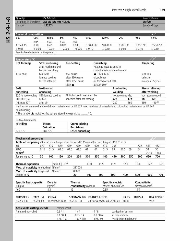
Part two • High-speed steels 159H
S 2-
9-1-
8 Quality HS 2-9-1-8 Technical cardAccording to standards UNI EN ISO 4957: 2002 TrafilixNumber (1.3247) Lucefin Group
Chemical compositionC% Si% Mn% P% S% Cr% Mo% V% W% Co%
max max max max1.05-1.15 0.70 0.40 0.030 0.030 3.50-4.50 9.0-10.0 0.90-1.30 1.20-1.90 7.50-8.50± 0.03 + 0.03 +0.04 + 0.005 + 0.005 ± 0.10 ± 0.10 ± 0.05 ± 0.10 ± 0.10Permissible deviations on the product.
Temperature °C Hot forming Stress relieving Pre-heating Quenching Tempering
after machining and Heatings must be done inbefore quenching controlled-atmosphere furnace
1100-900 600-650 450 pause ▲ 1170-1210 530-560furnace cooling after 860 pause oil, polymer, calm airto 320 after, air after 1050 pause air forced or salt bath minimum 2 cycles
after ▲ at 500-550°Soft Isothermal Pre-heating Stress relievingannealing annealing welding after welding820 furnace cooling 890 furnace cooling not recommended not recommended600 afterr, air to 650 Ac1 Ac3 Ms Mf(HB max 277) after air 780 860 160 –10 b)
Hardness of annealed and cold-drawn material can be HB 327 max. Hardness of annealed and cold-rolled material can be HB 347b) subcooling* The symbol ▲ indicates the temperature increase up to ……. °C.
Thermal expansion [m/(m·K)] ·10–6 11.0 11.5 11.9 12.3 12.4 12.5 12.5Mod. of elasticity longitudinal N/mm2 217000Mod. of elasticity tangenzial N/mm2 83000Testing at °C 20 100 200 300 400 500 600 700
EUROPE EN ITALY UNI CHINA GERMANY DIN FRANCE AFNOR UK BS RUSSIA USA AISI/SAE HS 2-9-1-8 HS 2-9-1-8 W2Mo9Cr4VCo8 HS 2-10-1-8 Z110DKCWV09-08-04-02-01 BM42 M42
Mechanical propertiesTable of tempering values at room temperature for round Ø 15 mm after quenching at 1190 °C in oilHB 679 679 679 679 679 670 670 679 706 722 543 482HRC 61.5 61.5 61.5 61.5 61.5 61 61 61.5 63 67.5 69 64 54 50N/mm2 2010 1760Tempering at °C 50 100 150 200 250 300 350 400 450 500 550 600 650 700
Achievable cutting speeds carbide insertAnnealed hot-rolled 0.5 / 1 1 / 4 4 / 8 ap depth of cut mm
0.1 / 0.3 0.2 / 0.4 0.3 / 0.6 fn feed mm/rev210 / 150 160 / 110 110 / 80 Vc cutting speed m/min
Specific heat capacity Density Thermal Specific electric ConductivityJ/(kg·K) kg/dm3 conductivity W/(m·K) resist. ohm·mm2/m siemens·m/mm2
460 8.3 19 0.65 1.54
All high-speed steels must beannealed after hot forming
Surface treatmentsNitriding Steam Crome-plating
Oxidation Burnishing520-570 380-520 Laser quenching
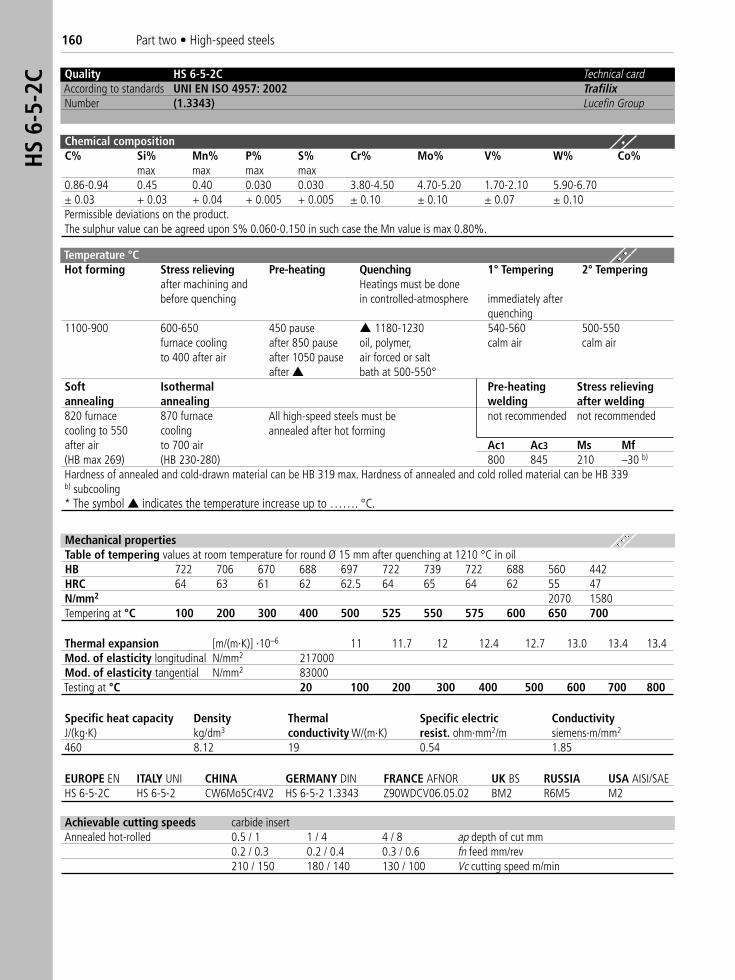
160 Part two • High-speed steelsH
S 6-
5-2C
Thermal expansion [m/(m·K)] ·10–6 11 11.7 12 12.4 12.7 13.0 13.4 13.4Mod. of elasticity longitudinal N/mm2 217000Mod. of elasticity tangential N/mm2 83000Testing at °C 20 100 200 300 400 500 600 700 800
EUROPE EN ITALY UNI CHINA GERMANY DIN FRANCE AFNOR UK BS RUSSIA USA AISI/SAE HS 6-5-2C HS 6-5-2 CW6Mo5Cr4V2 HS 6-5-2 1.3343 Z90WDCV06.05.02 BM2 R6M5 M2
Mechanical propertiesTable of tempering values at room temperature for round Ø 15 mm after quenching at 1210 °C in oilHB 722 706 670 688 697 722 739 722 688 560 442HRC 64 63 61 62 62.5 64 65 64 62 55 47N/mm2 2070 1580Tempering at °C 100 200 300 400 500 525 550 575 600 650 700
Achievable cutting speeds carbide insertAnnealed hot-rolled 0.5 / 1 1 / 4 4 / 8 ap depth of cut mm
0.2 / 0.3 0.2 / 0.4 0.3 / 0.6 fn feed mm/rev210 / 150 180 / 140 130 / 100 Vc cutting speed m/min
Specific heat capacity Density Thermal Specific electric ConductivityJ/(kg·K) kg/dm3 conductivity W/(m·K) resist. ohm·mm2/m siemens·m/mm2
460 8.12 19 0.54 1.85
Quality HS 6-5-2C Technical cardAccording to standards UNI EN ISO 4957: 2002 TrafilixNumber (1.3343) Lucefin Group
Chemical compositionC% Si% Mn% P% S% Cr% Mo% V% W% Co%
max max max max0.86-0.94 0.45 0.40 0.030 0.030 3.80-4.50 4.70-5.20 1.70-2.10 5.90-6.70± 0.03 + 0.03 + 0.04 + 0.005 + 0.005 ± 0.10 ± 0.10 ± 0.07 ± 0.10Permissible deviations on the product.The sulphur value can be agreed upon S% 0.060-0.150 in such case the Mn value is max 0.80%.
Temperature °C Hot forming Stress relieving Pre-heating Quenching 1° Tempering 2° Tempering
after machining and Heatings must be done before quenching in controlled-atmosphere immediately after
quenching1100-900 600-650 450 pause ▲ 1180-1230 540-560 500-550
furnace cooling after 850 pause oil, polymer, calm air calm airto 400 after air after 1050 pause air forced or salt
after ▲ bath at 500-550°Soft Isothermal Pre-heating Stress relievingannealing annealing welding after welding820 furnace 870 furnace not recommended not recommendedcooling to 550 coolingafter air to 700 air Ac1 Ac3 Ms Mf(HB max 269) (HB 230-280) 800 845 210 –30 b)
Hardness of annealed and cold-drawn material can be HB 319 max. Hardness of annealed and cold rolled material can be HB 339b) subcooling* The symbol ▲ indicates the temperature increase up to ……. °C.
All high-speed steels must beannealed after hot forming
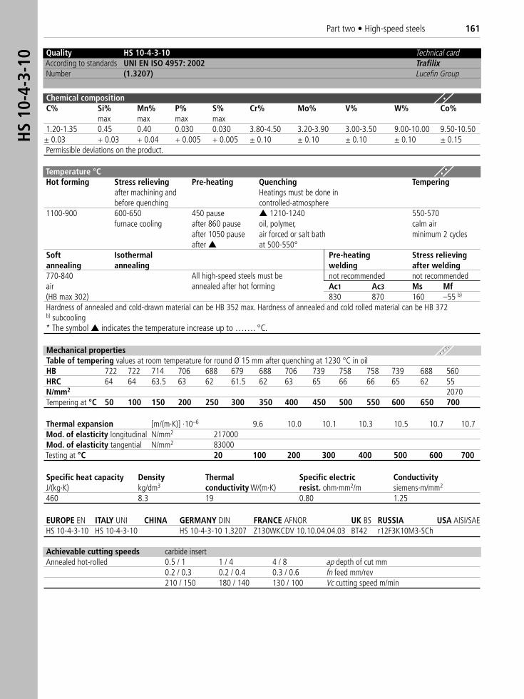
Part two • High-speed steels 161H
S 10
-4-3
-10 Quality HS 10-4-3-10 Technical card
According to standards UNI EN ISO 4957: 2002 TrafilixNumber (1.3207) Lucefin Group
Chemical compositionC% Si% Mn% P% S% Cr% Mo% V% W% Co%
max max max max1.20-1.35 0.45 0.40 0.030 0.030 3.80-4.50 3.20-3.90 3.00-3.50 9.00-10.00 9.50-10.50
± 0.03 + 0.03 + 0.04 + 0.005 + 0.005 ± 0.10 ± 0.10 ± 0.10 ± 0.10 ± 0.15Permissible deviations on the product.
Temperature °C Hot forming Stress relieving Pre-heating Quenching Tempering
after machining and Heatings must be done in before quenching controlled-atmosphere
1100-900 600-650 450 pause ▲ 1210-1240 550-570furnace cooling after 860 pause oil, polymer, calm air
after 1050 pause air forced or salt bath minimum 2 cyclesafter ▲ at 500-550°
Soft Isothermal Pre-heating Stress relievingannealing annealing welding after welding770-840 not recommended not recommendedair Ac1 Ac3 Ms Mf(HB max 302) 830 870 160 –55 b)
Hardness of annealed and cold-drawn material can be HB 352 max. Hardness of annealed and cold rolled material can be HB 372b) subcooling* The symbol ▲ indicates the temperature increase up to ……. °C.
Thermal expansion [m/(m·K)] ·10–6 9.6 10.0 10.1 10.3 10.5 10.7 10.7Mod. of elasticity longitudinal N/mm2 217000Mod. of elasticity tangential N/mm2 83000Testing at °C 20 100 200 300 400 500 600 700
EUROPE EN ITALY UNI CHINA GERMANY DIN FRANCE AFNOR UK BS RUSSIA USA AISI/SAE HS 10-4-3-10 HS 10-4-3-10 HS 10-4-3-10 1.3207 Z130WKCDV 10.10.04.04.03 BT42 r12F3K10M3-SCh
Mechanical propertiesTable of tempering values at room temperature for round Ø 15 mm after quenching at 1230 °C in oilHB 722 722 714 706 688 679 688 706 739 758 758 739 688 560HRC 64 64 63.5 63 62 61.5 62 63 65 66 66 65 62 55N/mm2 2070Tempering at °C 50 100 150 200 250 300 350 400 450 500 550 600 650 700
Achievable cutting speeds carbide insertAnnealed hot-rolled 0.5 / 1 1 / 4 4 / 8 ap depth of cut mm
0.2 / 0.3 0.2 / 0.4 0.3 / 0.6 fn feed mm/rev210 / 150 180 / 140 130 / 100 Vc cutting speed m/min
Specific heat capacity Density Thermal Specific electric ConductivityJ/(kg·K) kg/dm3 conductivity W/(m·K) resist. ohm·mm2/m siemens·m/mm2
460 8.3 19 0.80 1.25
All high-speed steels must beannealed after hot forming
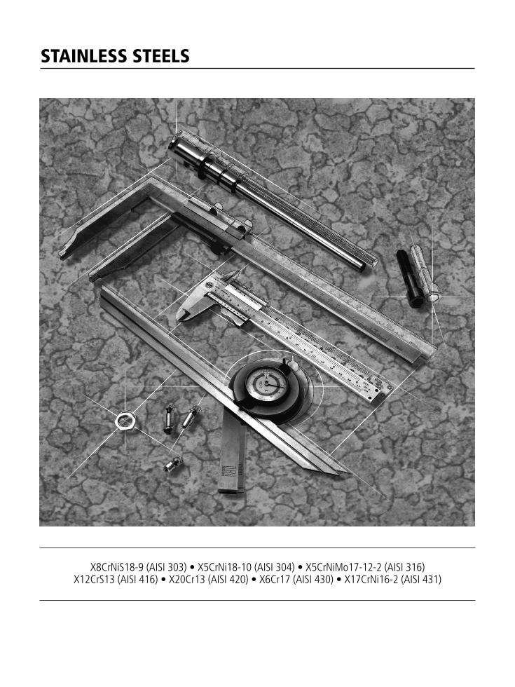
STAINLESS STEELS
X8CrNiS18-9 (AISI 303) • X5CrNi18-10 (AISI 304) • X5CrNiMo17-12-2 (AISI 316) X12CrS13 (AISI 416) • X20Cr13 (AISI 420) • X6Cr17 (AISI 430) • X17CrNi16-2 (AISI 431)
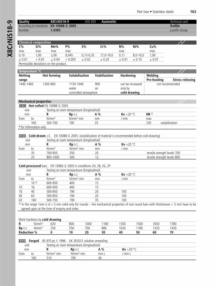
Part two • Stainless steels 163X8
CrN
iS18
-9 Quality X8CrNiS18-9 AISI 303 Austenitic Technical cardAccording to standards EN 10088-3: 2005 TrafilixNumber 1.4305 Lucefin Group
Chemical compositionC% Si% Mn% P% S% Cr% N% Ni% Cu%max max max max max max0,10 1,00 2,00 0,045 0,15-0,35 17,0-19,0 0,11 8,0-10,0 1,00± 0.01 + 0.05 ± 0.04 + 0.005 ± 0.02 ± 0.20 ± 0.01 ± 0.10 ± 0.07Permissible deviations on the product.
Temperature °C Melting Hot forming Solubilization Stabilization Hardening Weldingrange Pre-heating Stress relieving 1440-1460 1200-900 1150-1040 900 can be increased not recommended
water air only by controlled atmosphere cold drawing
Mechanical propertiesHot-rolled EN 10088-3: 2005
size Testing at room temperature (longitudinal)mm R Rp 0.2 A % Kv +20 °C HB a)
from to N/mm2 N/mm2 min min J min max160 500-700 190 35 230 solubilization
a) for information only
Cold-drawn +C EN 10088-3: 2005 (solubilization of material is recommended before cold drawing) nsize Testing at room temperature (longitudinal)mm R Rp 0.2 A % Kv +20 °C
from to N/mm2 N/mm2 min min J min35 700-850 350 20 tensile strength levels 70025 800-1000 500 12 tensile strength levels 800
Forged BS 970 pt.1: 1996 UK 303S31 solution annealingsize Testing at room temperature (longitudinal)mm R Rp 0.2 A % Kv +20 °C
from to N/mm2 min N/mm2 min min L J min L160 510 190 40
Cold processed bars EN 10083-3: 2005 in conditions 2H, 2B, 2G, 2Psize Testing at room temperature (longitudinal)mm R Rp 0.2 A % Kv +20 °C
from to N/mm2 N/mm2 min min J min10 a) 600-950 400 15
10 16 600-950 400 1516 40 500-850 190 20 10040 63 500-850 190 20 10063 160 500-750 190 35 100a) In the range 1mm ≤ d < 5 mm valid only for rounds – the mechanical properties of non round bars with thicknesses < 5 mm have to be
agreed upon at the time of enquiry and order.
Work-hardness by cold drawingR N/mm2 620 800 1000 1180 1350 1500 1650 1780Rp 0.2 N/mm2 250 550 700 880 1020 1180 1320 1430Reduction % 0 10 20 30 40 50 60 70
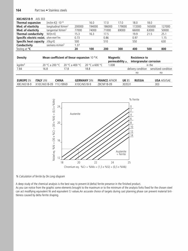
164 Part two • Stainless steels
X8CrNiS18-9 AISI 303Thermal expansion [m/(m·K)] ·10–6 16.0 17.0 17.0 18.0 18.0Mod. of elasticity longitudinal N/mm2 200000 194000 186000 179000 172000 165000 127000Mod. of elasticity tangential N/mm2 77000 74000 71000 69000 66000 63000 50000Thermal conductivity W/(m·K) 15.3 16.3 17.5 19.9 21.5 25.1Specific electric resist. ohm·mm2/m 0.73 0.86 0.97 1.15Specific heat capacity J/(kg·K) 500 510 550 630Conductivity siemens·m/mm2 1.37Testing at °C 20 100 200 300 400 500 800
Density Mean coefficient of linear expansion 10–6/K Magnetic Resistence topermeability μr intergranular corrosion
kg/dm3 20 °C a 200 °C 20 °C a 400 °C 20 °C a 600 °C 1.008 in the7.84 16.8 17.8 18.8 delivery condition sensitized condition
no no
EUROPE EN ITALY UNI CHINA GERMANY DIN FRANCE AFNOR UK BS RUSSIA USA AISI/SAEX8CrNiS18-9 X10CrNiS18-09 Y1Cr18Ni9 X10CrNiS18-9 Z8CNF18-09 303S31 303
Chromium eq. %Cr + %Mo + (1,5 x %Si) + (0,5 x %Nb)
Nick
el e
q. %
Ni +
(30
x %
C) +
(30
x %
N) +
(0,5
x %
Mn)
Austenite
Austenite+ Ferrite
02
46810
1214
24
20
16
12
18 20 22 24 25
% Ferrite
% Calculation of ferrite by De Long diagram
A deep study of the chemical analysis is the best way to prevent δ (delta) ferrite presence in the finished product.As you can notice from the graphic some elements brought to the maximum or to the minimum of the analysis forks fixed for the chosen steelcan act modifying equivalent Ni and equivalent Cr values.An accurate choice of targets during cast planning phase can prevent material brit-tleness caused by delta ferrite shaping.
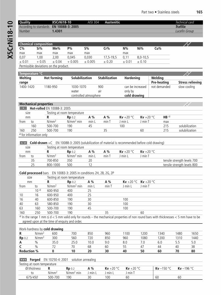
Part two • Stainless steels 165X5
CrN
i18-
10
Quality X5CrNi18-10 AISI 304 Austenitic Technical cardAccording to standards EN 10088-3: 2005 TrafilixNumber 1.4301 Lucefin Group
Chemical compositionC% Si% Mn% P% S% Cr% N% Ni% Cu%max max max max max max0,07 1,00 2,00 0,045 0,030 17,5-19,5 0,11 8,0-10,5± 0.01 + 0.05 ± 0.04 + 0.005 ± 0.005 ± 0.20 ± 0.01 ± 0.10Permissible deviations on the product.
Temperature °C Melting Hot forming Solubilization Stabilization Hardening Weldingrange Pre-heating Stress relieving 1400-1420 1180-950 1030-1070 900 can be increased not demanded slow cooling
water air only bycontrolled atmosphere cold drawing
Mechanical propertiesHot-rolled EN 10088-3: 2005
size Testing at room temperaturemm R Rp 0.2 A % A % Kv +20 °C Kv +20 °C HB a)
from to N/mm2 N/mm2 min min L min T J min L J min T max160 500-700 190 45 100 215 solubilization
160 250 500-700 190 35 60 215 solubilizationa) for information only
Cold-drawn +C EN 10088-3: 2005 (solubilization of material is recommended before cold drawing)size Testing at room temperaturemm R Rp 0.2 A % A % Kv +20 °C Kv +20 °C
from to N/mm2 N/mm2 min min L min T J min L J min T35 700-850 350 20 tensile strength levels 70025 800-1000 500 12 tensile strength levels 800
Forged EN 10250-4: 2001 solution annealingTesting at room temperature
Ø/thickness R Rp 0.2 A % Kv +20 °C Kv +20 °C Kv –150 °C Kv –196 °Cto N/mm2 N/mm2 min J min L J min L J min T
675/450 500-700 190 30 100 60 60 60
Cold processed bars EN 10083-3: 2005 in conditions 2H, 2B, 2G, 2Psize Testing at room temperaturemm R Rp 0.2 A % A % Kv +20 °C Kv +20 °C
from to N/mm2 N/mm2 min min L min T J min L J min T10 a) 600-950 400 25
10 16 600-950 400 2516 40 600-850 190 30 10040 63 580-850 190 30 10063 160 500-700 190 45 100160 250 500-700 190 35 60a) In the range 1 mm ≤ d < 5 mm valid only for rounds – the mechanical properties of non round bars with thicknesses < 5 mm have to be
agreed upon at the time of enquiry and order.
Work-hardness by cold drawingR N/mm2 600 700 850 960 1100 1200 1340 1480 1650Rp 0.2 N/mm2 300 560 720 850 960 1080 1200 1310 1440A % 35.0 25.0 10.0 9.0 8.0 7.0 6.0 5.5 5.0C % 72 70 68 60 55 47 44 40 38Reduction % 0 10 20 30 40 50 60 70 80
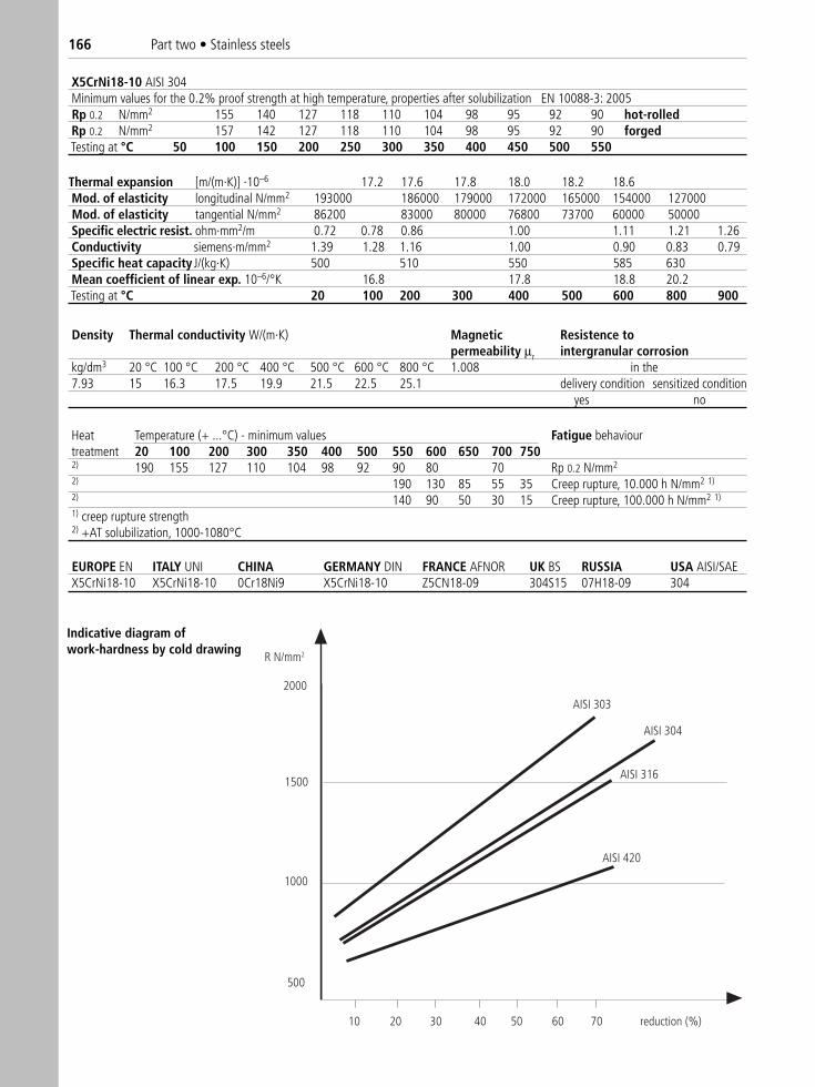
166 Part two • Stainless steels
X5CrNi18-10 AISI 304Minimum values for the 0.2% proof strength at high temperature, properties after solubilization EN 10088-3: 2005Rp 0.2 N/mm2 155 140 127 118 110 104 98 95 92 90 hot-rolledRp 0.2 N/mm2 157 142 127 118 110 104 98 95 92 90 forgedTesting at °C 50 100 150 200 250 300 350 400 450 500 550
EUROPE EN ITALY UNI CHINA GERMANY DIN FRANCE AFNOR UK BS RUSSIA USA AISI/SAEX5CrNi18-10 X5CrNi18-10 0Cr18Ni9 X5CrNi18-10 Z5CN18-09 304S15 07H18-09 304
Thermal expansion [m/(m·K)] ·10–6 17.2 17.6 17.8 18.0 18.2 18.6Mod. of elasticity longitudinal N/mm2 193000 186000 179000 172000 165000 154000 127000Mod. of elasticity tangential N/mm2 86200 83000 80000 76800 73700 60000 50000Specific electric resist. ohm·mm2/m 0.72 0.78 0.86 1.00 1.11 1.21 1.26Conductivity siemens·m/mm2 1.39 1.28 1.16 1.00 0.90 0.83 0.79Specific heat capacity J/(kg·K) 500 510 550 585 630Mean coefficient of linear exp. 10–6/°K 16.8 17.8 18.8 20.2Testing at °C 20 100 200 300 400 500 600 800 900
Density Thermal conductivity W/(m·K) Magnetic Resistence topermeability μr intergranular corrosion
kg/dm3 20 °C 100 °C 200 °C 400 °C 500 °C 600 °C 800 °C 1.008 in the7.93 15 16.3 17.5 19.9 21.5 22.5 25.1 delivery condition sensitized condition
yes no
Heat Temperature (+ ...°C) - minimum values Fatigue behaviourtreatment 20 100 200 300 350 400 500 550 600 650 700 7502) 190 155 127 110 104 98 92 90 80 70 Rp 0.2 N/mm2
2) 190 130 85 55 35 Creep rupture, 10.000 h N/mm2 1)
2) 140 90 50 30 15 Creep rupture, 100.000 h N/mm2 1)
1) creep rupture strength2) +AT solubilization, 1000-1080°C
10
2000
1500
1000
500
AISI 304
R N/mm2
20 30 40 50 60 70 reduction (%)
AISI 316
AISI 420
AISI 303
Indicative diagram of work-hardness by cold drawing
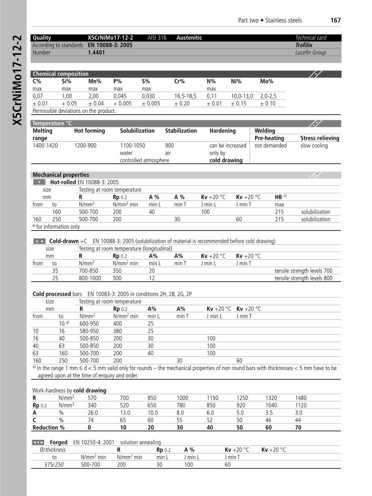
Part two • Stainless steels 167X5
CrN
iMo1
7-12
-2 Quality X5CrNiMo17-12-2 AISI 316 Austenitic Technical cardAccording to standards EN 10088-3: 2005 TrafilixNumber 1.4401 Lucefin Group
Chemical compositionC% Si% Mn% P% S% Cr% N% Ni% Mo%max max max max max max0,07 1,00 2,00 0,045 0,030 16,5-18,5 0,11 10,0-13,0 2,0-2,5± 0.01 + 0.05 ± 0.04 + 0.005 ± 0.005 ± 0.20 ± 0.01 ± 0.15 ± 0.10Permissible deviations on the product.
Temperature °C Melting Hot forming Solubilization Stabilization Hardening Weldingrange Pre-heating Stress relieving 1400-1420 1200-900 1100-1050 900 can be increased not demanded slow cooling
water air only bycontrolled atmosphere cold drawing
Mechanical propertiesHot-rolled EN 10088-3: 2005
size Testing at room temperaturemm R Rp 0.2 A % A % Kv +20 °C Kv +20 °C HB a)
from to N/mm2 N/mm2 min min L min T J min L J min T max160 500-700 200 40 100 215 solubilization
160 250 500-700 200 30 60 215 solubilizationa) for information only
Cold-drawn +C EN 10088-3: 2005 (solubilization of material is recommended before cold drawing)size Testing at room temperature (longitudinal)mm R Rp 0.2 A% A% Kv +20 °C Kv +20 °C
from to N/mm2 N/mm2 min min L min T J min L J min T35 700-850 350 20 tensile strength levels 70025 800-1000 500 12 tensile strength levels 800
Forged EN 10250-4: 2001 solution annealingØ/thickness R Rp 0.2 A % Kv +20 °C Kv +20 °C
to N/mm2 min N/mm2 min min L J min L J min T375/250 500-700 200 30 100 60
Cold processed bars EN 10083-3: 2005 in conditions 2H, 2B, 2G, 2P size Testing at room temperaturemm R Rp 0.2 A% A% Kv +20 °C Kv +20 °C
from to N/mm2 N/mm2 min min L min T J min L J min T10 a) 600-950 400 25
10 16 580-950 380 2516 40 500-850 200 30 10040 63 500-850 200 30 10063 160 500-700 200 40 100160 250 500-700 200 30 60a) In the range 1 mm ≤ d < 5 mm valid only for rounds – the mechanical properties of non round bars with thicknesses < 5 mm have to be
agreed upon at the time of enquiry and order.
Work-hardness by cold drawingR N/mm2 570 700 850 1000 1150 1250 1320 1480Rp 0.2 N/mm2 340 520 650 780 850 920 1040 1120A % 26.0 13.0 10.0 8.0 6.0 5.0 3.5 3.0C % 74 65 60 55 52 50 46 44Reduction % 0 10 20 30 40 50 60 70
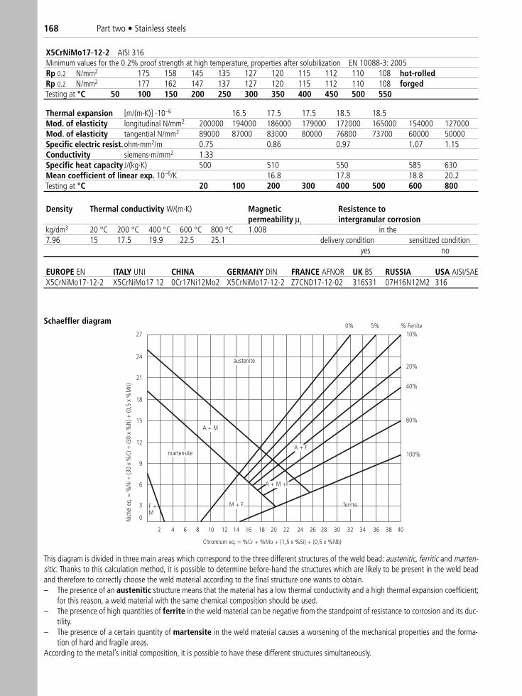
168 Part two • Stainless steels
X5CrNiMo17-12-2 AISI 316Minimum values for the 0.2% proof strength at high temperature, properties after solubilization EN 10088-3: 2005Rp 0.2 N/mm2 175 158 145 135 127 120 115 112 110 108 hot-rolledRp 0.2 N/mm2 177 162 147 137 127 120 115 112 110 108 forgedTesting at °C 50 100 150 200 250 300 350 400 450 500 550
EUROPE EN ITALY UNI CHINA GERMANY DIN FRANCE AFNOR UK BS RUSSIA USA AISI/SAE X5CrNiMo17-12-2 X5CrNiMo17 12 0Cr17Ni12Mo2 X5CrNiMo17-12-2 Z7CND17-12-02 316S31 07H16N12M2 316
Thermal expansion [m/(m·K)] ·10–6 16.5 17.5 17.5 18.5 18.5Mod. of elasticity longitudinal N/mm2 200000 194000 186000 179000 172000 165000 154000 127000Mod. of elasticity tangential N/mm2 89000 87000 83000 80000 76800 73700 60000 50000Specific electric resist.ohm·mm2/m 0.75 0.86 0.97 1.07 1.15Conductivity siemens·m/mm2 1.33Specific heat capacity J/(kg·K) 500 510 550 585 630Mean coefficient of linear exp. 10–6/K 16.8 17.8 18.8 20.2Testing at °C 20 100 200 300 400 500 600 800
Density Thermal conductivity W/(m·K) Magnetic Resistence topermeability μr intergranular corrosion
kg/dm3 20 °C 200 °C 400 °C 600 °C 800 °C 1.008 in the7.96 15 17.5 19.9 22.5 25.1 delivery condition sensitized condition
yes no
austenite
martensite
A + M
ferriteM + F
A + M +F
A + F
F +M
Chromium eq. = %Cr + %Mo + (1,5 x %Si) + (0,5 x %Nb)
Nich
el e
q. =
%N
i + (3
0 x
%C)
+ (3
0 x
%N
) + (0
,5 x
%M
n)
0
2 4 6 8 10 12 14 16 18 20 22 24 26 28 30 32 34 36 38 40
3
6
9
12
15
18
21
24
270% 5% % Ferrite
10%
20%
40%
80%
100%
This diagram is divided in three main areas which correspond to the three different structures of the weld bead: austenitic, ferritic and marten-sitic. Thanks to this calculation method, it is possible to determine before-hand the structures which are likely to be present in the weld beadand therefore to correctly choose the weld material according to the final structure one wants to obtain.– The presence of an austenitic structure means that the material has a low thermal conductivity and a high thermal expansion coefficient;
for this reason, a weld material with the same chemical composition should be used.– The presence of high quantities of ferrite in the weld material can be negative from the standpoint of resistance to corrosion and its duc-
tility.– The presence of a certain quantity of martensite in the weld material causes a worsening of the mechanical properties and the forma-
tion of hard and fragile areas.According to the metal’s initial composition, it is possible to have these different structures simultaneously.
Schaeffler diagram
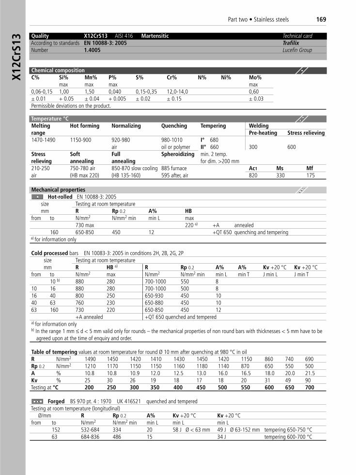
Part two • Stainless steels 169X1
2CrS
13
Quality X12CrS13 AISI 416 Martensitic Technical cardAccording to standards EN 10088-3: 2005 TrafilixNumber 1.4005 Lucefin Group
Chemical compositionC% Si% Mn% P% S% Cr% N% Ni% Mo%
max max max max0,06-0,15 1,00 1,50 0,040 0,15-0,35 12,0-14,0 0,60± 0.01 + 0.05 ± 0.04 + 0.005 ± 0.02 ± 0.15 ± 0.03Permissible deviations on the product.
Temperature °C Melting Hot forming Normalizing Quenching Tempering Weldingrange Pre-heating Stress relieving 1470-1490 1150-900 920-980 980-1010 I° 680
air oil or polymer II° 660 300 600Stress Soft Full Spheroidizing min. 2 temp.relieving annealing annealing for dim. >200 mm210-250 750-780 air 850-870 slow cooling 885 furnace Ac1 Ms Mfair (HB max 220) (HB 135-160) 595 after, air 820 330 175
Mechanical propertiesHot-rolled EN 10088-3: 2005
size Testing at room temperaturemm R Rp 0.2 A% HB
from to N/mm2 N/mm2 min min L max730 max 220 a) +A annealed
160 650-850 450 12 +QT 650 quenching and temperinga) for information only
Cold processed bars EN 10083-3: 2005 in conditions 2H, 2B, 2G, 2P size Testing at room temperaturemm R HB a) R Rp 0.2 A% A% Kv +20 °C Kv +20 °C
from to N/mm2 max N/mm2 N/mm2 min min L min T J min L J min T10 b) 880 280 700-1000 550 8
10 16 880 280 700-1000 500 816 40 800 250 650-930 450 1040 63 760 230 650-880 450 1063 160 730 220 650-850 450 12
+A annealed +QT 650 quenched and tempereda) for information onlyb) In the range 1 mm ≤ d < 5 mm valid only for rounds – the mechanical properties of non round bars with thicknesses < 5 mm have to be
agreed upon at the time of enquiry and order.
Forged BS 970 pt. 4 : 1970 UK 416S21 quenched and temperedTesting at room temperature (longitudinal)
Ø/mm R Rp 0.2 A% Kv +20 °C Kv +20 °Cfrom to N/mm2 N/mm2 min min L min L min L
152 532-684 334 20 58 J Ø < 63 mm 49 J Ø 63-152 mm tempering 650-750 °C63 684-836 486 15 34 J tempering 600-700 °C
Table of tempering values at room temperature for round Ø 10 mm after quenching at 980 °C in oilR N/mm2 1490 1450 1420 1410 1430 1450 1420 1150 860 740 690Rp 0.2 N/mm2 1210 1170 1150 1150 1160 1180 1140 870 650 550 500A % 10.8 10.8 10.9 12.0 12.5 13.0 16.0 16.5 18.0 20.0 21.5Kv % 25 30 26 19 18 17 18 20 31 49 90Testing at °C 200 250 300 350 400 450 500 550 600 650 700
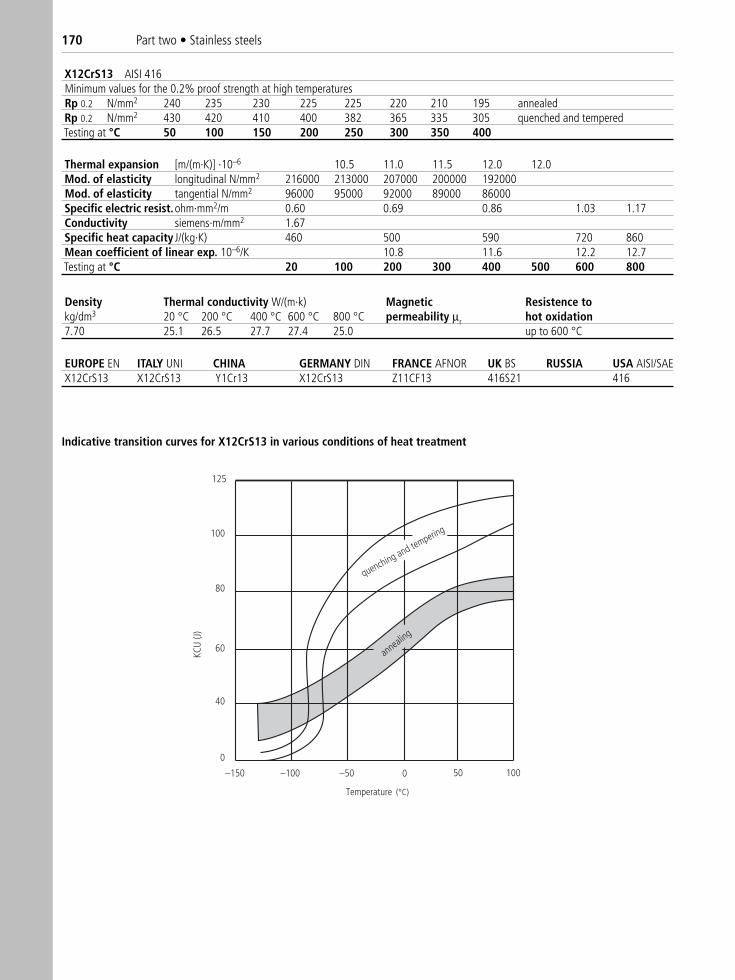
170 Part two • Stainless steels
X12CrS13 AISI 416Minimum values for the 0.2% proof strength at high temperaturesRp 0.2 N/mm2 240 235 230 225 225 220 210 195 annealedRp 0.2 N/mm2 430 420 410 400 382 365 335 305 quenched and temperedTesting at °C 50 100 150 200 250 300 350 400
EUROPE EN ITALY UNI CHINA GERMANY DIN FRANCE AFNOR UK BS RUSSIA USA AISI/SAE X12CrS13 X12CrS13 Y1Cr13 X12CrS13 Z11CF13 416S21 416
Thermal expansion [m/(m·K)] ·10–6 10.5 11.0 11.5 12.0 12.0Mod. of elasticity longitudinal N/mm2 216000 213000 207000 200000 192000Mod. of elasticity tangential N/mm2 96000 95000 92000 89000 86000Specific electric resist.ohm·mm2/m 0.60 0.69 0.86 1.03 1.17Conductivity siemens·m/mm2 1.67Specific heat capacity J/(kg·K) 460 500 590 720 860Mean coefficient of linear exp. 10–6/K 10.8 11.6 12.2 12.7Testing at °C 20 100 200 300 400 500 600 800
Density Thermal conductivity W/(m·k) Magnetic Resistence tokg/dm3 20 °C 200 °C 400 °C 600 °C 800 °C permeability μr hot oxidation7.70 25.1 26.5 27.7 27.4 25.0 up to 600 °C
KCU
(J)
quenching and tempering
annealing
–150 –100 –50 50 100
100
80
60
40
0
125
0
Temperature
Indicative transition curves for X12CrS13 in various conditions of heat treatment
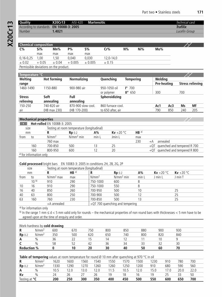
Part two • Stainless steels 171X2
0Cr1
3 Quality X20Cr13 AISI 420 Martensitic Technical cardAccording to standards EN 10088-3: 2005 TrafilixNumber 1.4021 Lucefin Group
Chemical compositionC% Si% Mn% P% S% Cr% N% Ni% Mo%
max max max max0,16-0,25 1,00 1,50 0,040 0,030 12,0-14,0± 0.02 + 0.05 ± 0.04 + 0.005 ± 0.005 ± 0.15Permissible deviations on the product.
Temperature °C Melting Hot forming Normalizing Quenching Tempering Weldingrange Pre-heating Stress relieving 1460-1490 1150-880 900-980 air 950-1050 oil I° 700
or polymer II° 650 300 700Stress Soft Full Spheroidizingrelieving annealing annealing150-250 740-820 air 870-900 slow cool. 860 furnace cool. Ac1 Ac3 Ms Mfair (HB max 230) (HB 170-200) to 650 after, air 790 850 240 205
Mechanical propertiesHot-rolled EN 10088-3: 2005
size Testing at room temperature (longitudinal)mm R Rp 0.2 A% Kv +20 °C HB a)
from to N/mm2 N/mm2 min min L Jmin L max760 max 230 +A annealed
160 700-850 500 13 25 +QT quenched and tempered R 700160 800-950 600 12 20 +QT quenched and tempered R 800
a) for information only
Cold processed bright bars EN 10083-3: 2005 in conditions 2H, 2B, 2G, 2Psize Testing at room temperature (longitudinal)mm R HB a) R Rp 0.2 A% Kv +20 °C Kv +20 °C
from to N/mm2 max max N/mm2 N/mm2 min min L J min L J min T10 b) 910 290 750-1000 600 8
10 16 910 290 750-1000 550 816 40 850 260 700-950 500 10 2540 63 800 250 700-900 500 12 2563 160 760 230 700-850 500 13 25
+A annealed +QT 700 quenching and temperinga) for information onlyb) In the range 1 mm ≤ d < 5 mm valid only for rounds – the mechanical properties of non round bars with thicknesses < 5 mm have to be
agreed upon at the time of enquiry and order.
Work-hardness by cold drawingR N/mm2 600 670 750 800 850 880 900 930Rp 0.2 N/mm2 350 500 620 650 740 800 820 840A % 36 22 15 14 12 11 10 9C % 58 52 42 36 34 33 32 30Reduction % 0 10 20 30 40 50 60 70
Table of tempering values at room temperature for round Ø 10 mm after quenching at 970 °C in oilR N/mm2 1620 1600 1560 1540 1550 1570 1500 1230 910 780 700Rp 0.2 N/mm2 1330 1290 1270 1260 1260 1250 1200 910 680 590 560A % 10.5 12.0 13.0 12.0 11.5 10.5 12.0 15.0 17.0 20.0 22.0Kv % 24 26 27 26 19 18 16 19 25 33 50Testing at °C 200 250 300 350 400 450 500 550 600 650 700
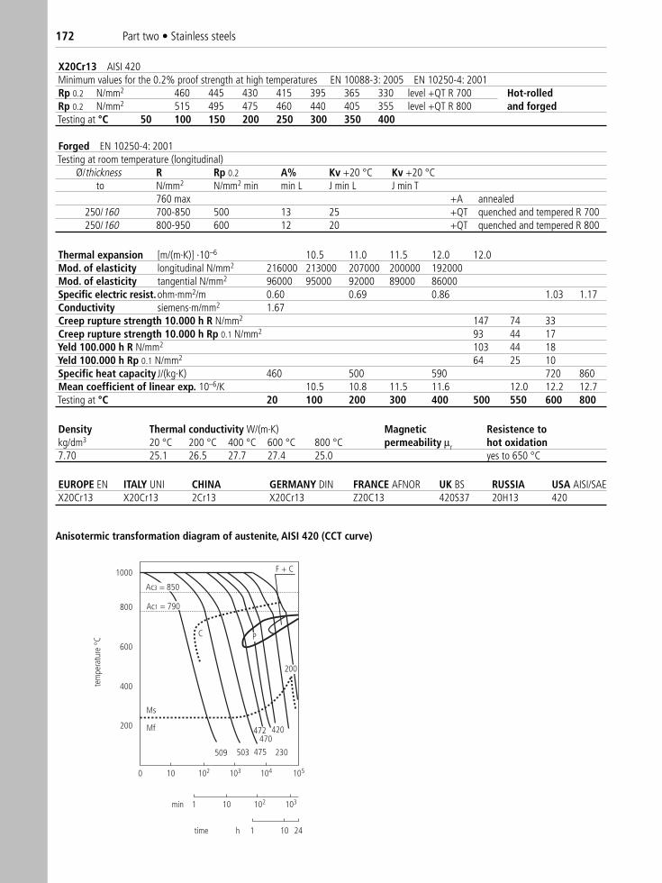
172 Part two • Stainless steels
X20Cr13 AISI 420Minimum values for the 0.2% proof strength at high temperatures EN 10088-3: 2005 EN 10250-4: 2001Rp 0.2 N/mm2 460 445 430 415 395 365 330 level +QT R 700 Hot-rolledRp 0.2 N/mm2 515 495 475 460 440 405 355 level +QT R 800 and forgedTesting at °C 50 100 150 200 250 300 350 400
EUROPE EN ITALY UNI CHINA GERMANY DIN FRANCE AFNOR UK BS RUSSIA USA AISI/SAE X20Cr13 X20Cr13 2Cr13 X20Cr13 Z20C13 420S37 20H13 420
Thermal expansion [m/(m·K)] ·10–6 10.5 11.0 11.5 12.0 12.0Mod. of elasticity longitudinal N/mm2 216000 213000 207000 200000 192000Mod. of elasticity tangential N/mm2 96000 95000 92000 89000 86000Specific electric resist.ohm·mm2/m 0.60 0.69 0.86 1.03 1.17Conductivity siemens·m/mm2 1.67Creep rupture strength 10.000 h R N/mm2 147 74 33Creep rupture strength 10.000 h Rp 0.1 N/mm2 93 44 17Yeld 100.000 h R N/mm2 103 44 18Yeld 100.000 h Rp 0.1 N/mm2 64 25 10Specific heat capacity J/(kg·K) 460 500 590 720 860Mean coefficient of linear exp. 10–6/K 10.5 10.8 11.5 11.6 12.0 12.2 12.7Testing at °C 20 100 200 300 400 500 550 600 800
Density Thermal conductivity W/(m·K) Magnetic Resistence tokg/dm3 20 °C 200 °C 400 °C 600 °C 800 °C permeability μr hot oxidation7.70 25.1 26.5 27.7 27.4 25.0 yes to 650 °C
F + C1000
800
600
400
200
509 503 475
472470
420
230
200
C P
Ms
Mf
0 10 102 103 104 105
10 102 1031
1 10 24h
min
time
tem
pera
ture
C
Ac3 = 850
Ac1 = 790
Anisotermic transformation diagram of austenite, AISI 420 (CCT curve)
Forged EN 10250-4: 2001Testing at room temperature (longitudinal)
Ø/thickness R Rp 0.2 A% Kv +20 °C Kv +20 °Cto N/mm2 N/mm2 min min L J min L J min T
760 max +A annealed250/160 700-850 500 13 25 +QT quenched and tempered R 700250/160 800-950 600 12 20 +QT quenched and tempered R 800
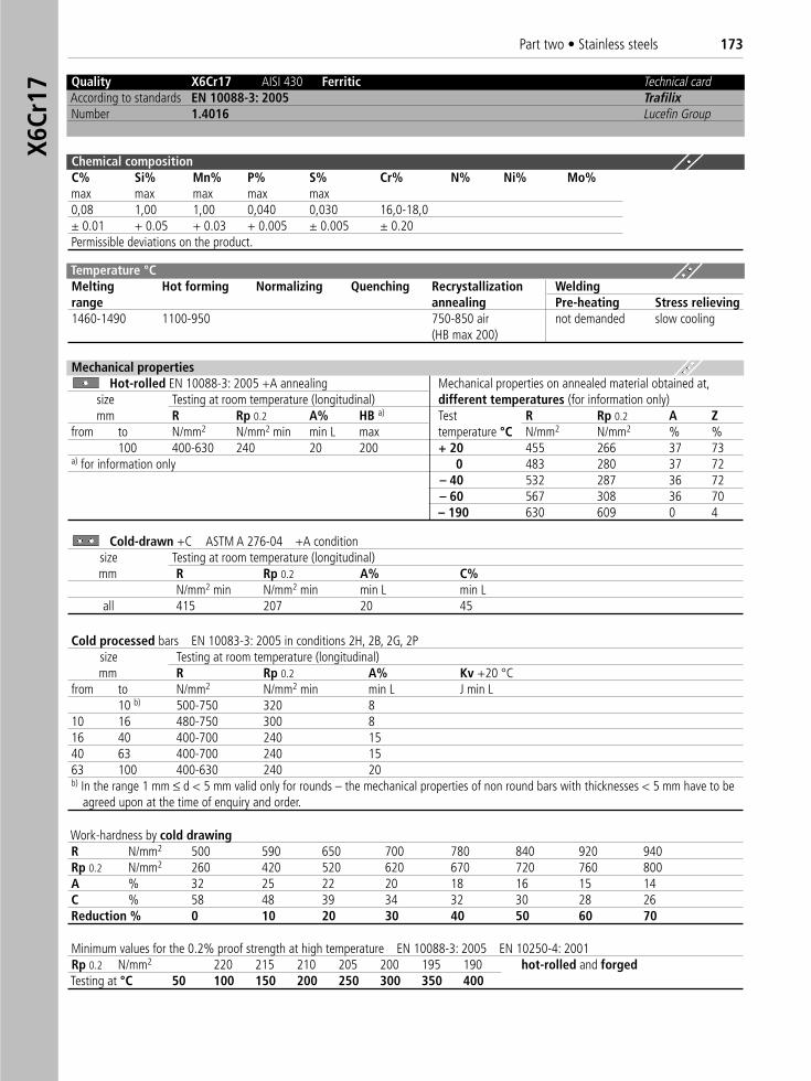
Part two • Stainless steels 173X6
Cr17
Minimum values for the 0.2% proof strength at high temperature EN 10088-3: 2005 EN 10250-4: 2001Rp 0.2 N/mm2 220 215 210 205 200 195 190 hot-rolled and forgedTesting at °C 50 100 150 200 250 300 350 400
Quality X6Cr17 AISI 430 Ferritic Technical cardAccording to standards EN 10088-3: 2005 TrafilixNumber 1.4016 Lucefin Group
Chemical compositionC% Si% Mn% P% S% Cr% N% Ni% Mo%max max max max max0,08 1,00 1,00 0,040 0,030 16,0-18,0± 0.01 + 0.05 + 0.03 + 0.005 ± 0.005 ± 0.20Permissible deviations on the product.
Temperature °C Melting Hot forming Normalizing Quenching Recrystallization Weldingrange annealing Pre-heating Stress relieving 1460-1490 1100-950 750-850 air not demanded slow cooling
(HB max 200)
Mechanical propertiesHot-rolled EN 10088-3: 2005 +A annealing Mechanical properties on annealed material obtained at,
size Testing at room temperature (longitudinal) different temperatures (for information only)mm R Rp 0.2 A% HB a) Test R Rp 0.2 A Z
from to N/mm2 N/mm2 min min L max temperature °C N/mm2 N/mm2 % %100 400-630 240 20 200 + 20 455 266 37 73
a) for information only 0 483 280 37 72– 40 532 287 36 72– 60 567 308 36 70– 190 630 609 0 4
Cold-drawn +C ASTM A 276-04 +A conditionsize Testing at room temperature (longitudinal)mm R Rp 0.2 A% C%
N/mm2 min N/mm2 min min L min Lall 415 207 20 45
Cold processed bars EN 10083-3: 2005 in conditions 2H, 2B, 2G, 2P size Testing at room temperature (longitudinal)mm R Rp 0.2 A% Kv +20 °C
from to N/mm2 N/mm2 min min L J min L10 b) 500-750 320 8
10 16 480-750 300 816 40 400-700 240 1540 63 400-700 240 1563 100 400-630 240 20b) In the range 1 mm ≤ d < 5 mm valid only for rounds – the mechanical properties of non round bars with thicknesses < 5 mm have to be
agreed upon at the time of enquiry and order.
Work-hardness by cold drawingR N/mm2 500 590 650 700 780 840 920 940Rp 0.2 N/mm2 260 420 520 620 670 720 760 800A % 32 25 22 20 18 16 15 14C % 58 48 39 34 32 30 28 26Reduction % 0 10 20 30 40 50 60 70
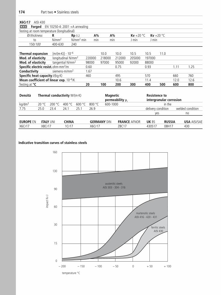
174 Part two • Stainless steels
X6Cr17 AISI 430Forged EN 10250-4: 2001 +A annealing
Testing at room temperature (longitudinal)Ø/thickness R Rp 0.2 A% A% Kv +20 °C Kv +20 °C
to N/mm2 N/mm2 min min min J min J min 150/100 400-630 240
EUROPE EN ITALY UNI CHINA GERMANY DIN FRANCE AFNOR UK BS RUSSIA USA AISI/SAE X6Cr17 X8Cr17 1Cr17 X6Cr17 Z8C17 430S17 08H17 430
Thermal expansion [m/(m·K)] · 10–6 10.0 10.0 10.5 10.5 11.0Mod. of elasticity longitudinal N/mm2 220000 218000 212000 205000 197000Mod. of elasticity tangential N/mm2 98000 97000 95000 92000 88000Specific electric resist.ohm·mm2/m 0.60 0.75 0.93 1.11 1.25Conductivity siemens·m/mm2 1.67Specific heat capacity J/(kg·K) 460 495 570 660 760Mean coefficient of linear exp. 10–6/K 10.6 11.4 12.0 12.6Testing at °C 20 100 200 300 400 500 600 800
Densità Thermal conductivity W/(m·K) Magnetic Resistence topermeability μr intergranular corrosion
kg/dm3 20 °C 200 °C 400 °C 600 °C 800 °C 600-1000 in the7.75 25.0 23.4 24.1 25.1 26.9 delivery condition welded condition
yes no
160
130
90
60
30
15
0
– 200 – 150 – 100 – 50 0 + 50 + 100
temperature C
austenitic steelsAISI 303 - 304 - 316
martensitic steelsAISI 416 - 420 - 431
ferritic steelsAISI 430
impa
ct K
v J
Indicative transition curves of stainless steels

Part two • Stainless steels 175X1
7CrN
i16-
2 Quality X17CrNi16-2 AISI 431 Martensitic Technical cardAccording to standards EN 10088-3: 2005 TrafilixNumber 1.4057 Lucefin Group
Chemical compositionC% Si% Mn% P% S% Cr% N% Ni% Mo%
max max max max0,12-0,22 1,00 1,50 0,040 0,030 15,0-17,0 1,50-2,50± 0.01 + 0.05 ± 0.04 + 0.005 ± 0.005 ± 0.20 ± 0.07Permissible deviations on the product.
Temperature °CMelting Hot forming Normalizing Quenching Tempering Weldingrange Pre-heating Stress relieving 1440-1460 1100-900 950-1000 980-1030 600-670 (R 900) 300 600
air oil or polymer 740-790 (R 800)Stress relieving Soft annealing Soft annealing210-250 750-780 air 620-670 Ac1 Ms Mfair (HB 240-295) short stay time (HB 240-285) long stay time 725 145 105
Cold processed bars EN 10083-3: 2005 in conditions 2H, 2B, 2G, 2P size Testing at room temperature (longitudinal)mm R HB a) R Rp 0.2 A% A% Kv +20 °C Kv +20 °C
from to N/mm2 max max N/mm2 N/mm2 min min L min T J min L J min T10 b) 1050 330 850-1100 750 7
10 16 1050 330 850-1100 700 716 40 1000 310 800-1050 650 9 2540 63 950 295 800-1000 650 12 2563 160 950 295 800-950 650 12 20
+A annealing +QT 800 quenching and temperinga) for information onlyb) In the range 1 mm ≤ d < 5 mm valid only for rounds – the mechanical properties of non round bars with thicknesses < 5 mm have to be
agreed upon at the time of enquiry and order.
Table of tempering value at room temperature for round Ø 10 mm after quenching at 1000 °C in oilR N/mm2 1400 1360 1320 1320 1325 1300 1250 1100 930 800 690Rp 0.2 N/mm2 1160 1160 1155 1140 1110 1080 1000 880 760 680 590A % 9.0 10.0 12.0 13.0 13.0 12.0 12.0 13.5 15.0 16.0 16.5Kv % 10 12 13 13 12 11 12 16 23 25 30Tempering at °C 200 250 300 350 400 450 500 550 600 650 700
Minimum values for the 0.2% proof strength at high temperature EN 10088-3: 2005Rp 0.2 N/mm2 515 495 475 460 440 405 355 resistance at 800Rp 0.2 N/mm2 565 525 505 490 470 430 375 resistance at 900Testing at °C 50 100 150 200 250 300 350 400
Mechanical propertiesHot-rolled EN 10088-3: 2005
size Testing at room temperature (longitudinal)mm R Rp 0.2 A% Kv +20 °C HB
from to N/mm2 N/mm2 min min L J min max950 max 295 a) +A annealing
60 800-950 600 14 25 +QT quenching and tempering R 80060 160 800-950 600 12 20
60 900-1050 700 12 20 +QT quenching and tempering R 90060 160 900-1050 700 10 15a) for information only
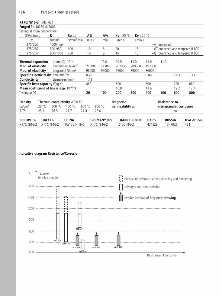
176 Part two • Stainless steels
X17CrNi16-2 AISI 431Forged EN 10250-4: 2001 Testing at room temperature
Ø/thickness R Rp 0.2 A% A% Kv +20 °C Kv +20 °Cto N/mm2 N/mm2 min min L min T J min L J min T
375/250 1000 max +A annealed375/250 800-950 600 10 8 20 15 +QT quenched and tempered R 800375/250 900-1050 700 10 8 15 10 +QT quenched and tempered R 900
Thermal expansion [m/(m·K)] ·10–6 10.0 10.5 11.0 11.0 11.0Mod. of elasticity longitudinal N/mm2 216000 213000 207000 200000 192000Mod. of elasticity tangential N/mm2 96000 95000 92000 89000 86000Specific electric resist.ohm·mm2/m 0.70 0.86 1.03 1.17Conductivity siemens·m/mm2 1.43Specific heat capacity J/(kg·K) 460 500 590 720 860Mean coefficient of linear exp. 10–6/°K 10.8 11.6 12.2 12.7Testing at °C 20 100 200 300 400 500 600 800
Density Thermal conductivity W/(m·K) Magnetic Resistence tokg/dm3 20 °C 200 °C 400 °C 600 °C 800 °C permeability μr intergranular corrosion7.75 25.1 26.5 27.7 27.4 25.0 no
EUROPE EN ITALY UNI CHINA GERMANY DIN FRANCE AFNOR UK BS RUSSIA USA AISI/SAE X17CrNi16-2 X17CrNi16-2 1Cr17CrNi16-2 X17CrNi16-2 Z15CN16-2 431S29 17HI6N2 431
R
1600
1400
1200
1000
800
600
400
R N/mm2
Tensile strenght increase of resistance after quenching and tempering
delivery state characteristics
possible increase of R by cold-drawing
Resistance of corrosion
AISI 316AISI 304
AISI 430
AISI 303
AISI 431
AISI 416AISI 420
Indicative diagram Resistance/Corrosion
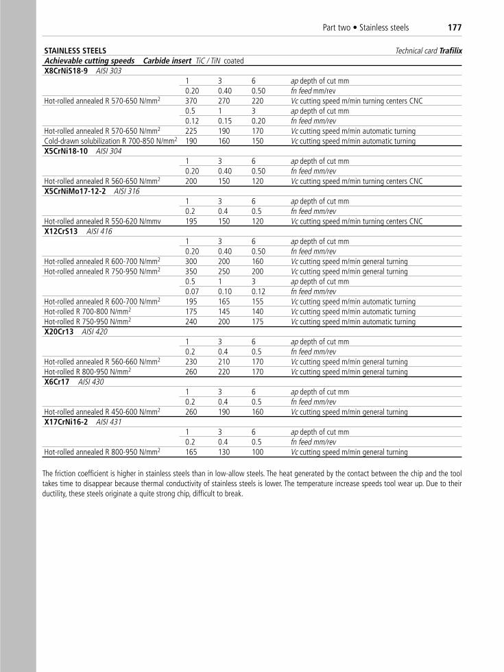
Part two • Stainless steels 177
STAINLESS STEELS Technical card TrafilixAchievable cutting speeds Carbide insert TiC / TiN coatedX8CrNiS18-9 AISI 303
1 3 6 ap depth of cut mm 0.20 0.40 0.50 fn feed mm/rev
Hot-rolled annealed R 570-650 N/mm2 370 270 220 Vc cutting speed m/min turning centers CNC0.5 1 3 ap depth of cut mm 0.12 0.15 0.20 fn feed mm/rev
Hot-rolled annealed R 570-650 N/mm2 225 190 170 Vc cutting speed m/min automatic turningCold-drawn solubilization R 700-850 N/mm2 190 160 150 Vc cutting speed m/min automatic turningX5CrNi18-10 AISI 304
1 3 6 ap depth of cut mm 0.20 0.40 0.50 fn feed mm/rev
Hot-rolled annealed R 560-650 N/mm2 200 150 120 Vc cutting speed m/min turning centers CNCX5CrNiMo17-12-2 AISI 316
1 3 6 ap depth of cut mm0.2 0.4 0.5 fn feed mm/rev
Hot-rolled annealed R 550-620 N/mmv 195 150 120 Vc cutting speed m/min turning centers CNCX12CrS13 AISI 416
1 3 6 ap depth of cut mm0.20 0.40 0.50 fn feed mm/rev
Hot-rolled annealed R 600-700 N/mm2 300 200 160 Vc cutting speed m/min general turningHot-rolled annealed R 750-950 N/mm2 350 250 200 Vc cutting speed m/min general turning
0.5 1 3 ap depth of cut mm0.07 0.10 0.12 fn feed mm/rev
Hot-rolled annealed R 600-700 N/mm2 195 165 155 Vc cutting speed m/min automatic turningHot-rolled R 700-800 N/mm2 175 145 140 Vc cutting speed m/min automatic turningHot-rolled R 750-950 N/mm2 240 200 175 Vc cutting speed m/min automatic turningX20Cr13 AISI 420
1 3 6 ap depth of cut mm0.2 0.4 0.5 fn feed mm/rev
Hot-rolled annealed R 560-660 N/mm2 230 210 170 Vc cutting speed m/min general turningHot-rolled R 800-950 N/mm2 260 220 170 Vc cutting speed m/min general turningX6Cr17 AISI 430
1 3 6 ap depth of cut mm0.2 0.4 0.5 fn feed mm/rev
Hot-rolled annealed R 450-600 N/mm2 260 190 160 Vc cutting speed m/min general turningX17CrNi16-2 AISI 431
1 3 6 ap depth of cut mm0.2 0.4 0.5 fn feed mm/rev
Hot-rolled annealed R 800-950 N/mm2 165 130 100 Vc cutting speed m/min general turning
The friction coefficient is higher in stainless steels than in low-allow steels. The heat generated by the contact between the chip and the tooltakes time to disappear because thermal conductivity of stainless steels is lower. The temperature increase speeds tool wear up. Due to theirductility, these steels originate a quite strong chip, difficult to break.
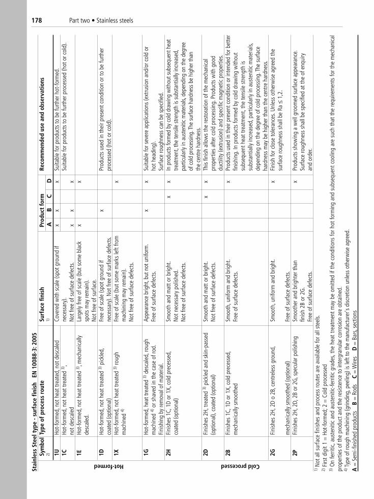
178 Part two • Stainless steels
Stai
nles
s St
eel t
ype
- sur
face
fini
shEN
100
88-3
: 200
5Sy
mbo
lTy
pe o
f pro
cess
rou
teSu
rfac
e fin
ish
Prod
uct
form
Reco
mm
ende
d us
e an
d ob
serv
atio
ns2)
1)A
BC
D1U
Hot-f
orm
ed, n
ot h
eat t
reat
ed, n
ot d
esca
led
Cove
red
with
sca
le (s
pot g
roun
d if
xx
xSu
itabl
e fo
r pro
duct
s to
be
furth
er h
ot-fo
rmed
.1C
Hot-f
orm
ed, n
ot h
eat t
reat
ed 3)
, ne
cess
ary)
. Su
itabl
e fo
r pro
duct
s to
be
furth
er p
roce
ssed
(hot
or c
old)
.no
t des
cale
dN
ot fr
ee o
f sur
face
def
ects
.x
xx
1EHo
t-for
med
, not
hea
t tre
ated
3), m
echa
nica
llyLa
rgel
y fre
e of
sca
le (b
ut s
ome
blac
kx
xde
scal
ed.
spot
s m
ay re
mai
n).
Not
free
of s
urfa
ce.
1DHo
t-for
med
, not
hea
t tre
ated
3)pi
ckle
d,Fr
ee o
f sca
le (s
pot g
roun
d if
xPr
oduc
ts u
sed
in th
eir p
rese
nt c
ondi
tion
or to
be
furth
erco
ated
(opt
iona
l)ne
cess
ary)
. Not
free
of s
urfa
ce d
efec
ts.
proc
esse
d (h
ot o
r col
d).
1XHo
t-for
med
, not
hea
t tre
ated
3)ro
ugh
Free
of s
cale
(but
som
e m
arks
left
from
xm
achi
ned
4)m
achi
ning
may
rem
ain)
.N
ot fr
ee o
f sur
face
def
ects
.
1GHo
t-for
med
, hea
t tre
ated
3)de
scal
ed, r
ough
Appe
aran
ce b
right
, but
not
uni
form
. x
xSu
itabl
e fo
r sev
ere
appl
icatio
ns (e
xtru
sion
and/
or c
old
orm
achi
ned
4)or
sha
ved
in th
e ca
se o
f rod
. Fr
ee o
f sur
face
def
ects
.ho
t hea
ding
).Fi
nish
ing
by re
mov
al o
f mat
eria
l.Su
rface
roug
hnes
s ca
n be
spe
cifie
d.
2HFi
nish
es 1
C, 1
D or
1X,
col
d pr
eces
sed,
Sm
ooth
and
mat
t or b
right
. x
xIn
pro
duct
s for
med
by
cold
dra
win
g w
ithou
t sub
sequ
ent h
eat
coat
ed (o
ptio
nal)
Not
nec
essa
ry p
olish
ed.
treat
men
t, th
e te
nsile
stre
ngth
is su
bsta
ntia
lly in
crea
sed,
Not
free
of s
urfa
ce d
efec
ts.
parti
cula
rly in
aus
teni
tic m
ater
ials,
dep
endi
ng o
n th
e de
gree
of
col
d pr
oces
sing.
The
surfa
ce h
ardn
ess b
e hi
gher
than
th
e ce
ntre
har
dnes
s.2D
Fini
shes
2H,
trea
ted
3)pi
ckle
d an
d sk
in-p
asse
dSm
ooth
and
mat
t or b
right
. x
xTh
is fin
ish a
llow
s th
e re
stor
atio
n of
the
mec
hani
cal
(opt
iona
l), c
oate
d(o
ptio
nal)
Not
free
of s
urfa
ce d
efec
ts.
prop
ertie
s af
ter c
old
proc
essin
g. P
rodu
cts
with
goo
d du
ctili
ty (e
xtru
sion)
and
spe
cific
mag
netic
pro
perti
es.
2BFi
nish
es 1
C, 1
D or
1X,
col
d pr
eces
sed,
Sm
ooth
, uni
form
and
brig
ht.
xPr
oduc
ts u
sed
in th
eir p
rese
nt c
ondi
tion
or in
tend
ed fo
r bet
ter
mec
hani
cally
sm
ooth
edFr
ee o
f sur
face
def
ects
.fin
ishin
g. In
pro
duct
s fo
rmed
by
cold
dra
win
g w
ithou
tsu
bseq
uent
hea
t tre
atm
ent,
the
tens
ile s
treng
th is
su
bsta
ntia
lly in
crea
sed,
par
ticul
arly
in a
uste
nitic
mat
eria
ls,
depe
ndin
g on
the
degr
ee o
f col
d pr
oces
sing.
The
surfa
ce
hard
ness
may
be
high
er th
an th
e ce
ntre
har
dnes
s.2G
Fini
shes
2H,
2D
o 2B
, cen
trele
ss g
roun
d,
Smoo
th, u
nifo
rm a
nd b
right
.x
Fini
sh fo
r clo
se to
lera
nces
. Unl
ess
othe
rwise
agr
eed
the
surfa
ce ro
ughn
ess
shal
l be
Ra ≤
1,2.
mec
hani
cally
sm
ooth
ed (o
ptio
nal)
Free
of s
urfa
ce d
efec
ts.
2PFi
nish
es 2
H, 2
D, 2
B or
2G,
spe
cula
r pol
ishin
gSm
ooth
er a
nd b
right
er th
an
xPr
oduc
ts s
how
ing
a w
ell g
room
ed s
urfa
ce a
ppea
ranc
e.
finish
2B
or 2
G.
Surfa
ce ro
ughn
ess
shal
l be
spec
ified
at t
he o
f enq
uiry
Fr
ee o
f sur
face
def
ects
.an
d or
der.
1)N
ot a
ll su
rface
fini
shes
and
pro
cess
rout
es a
re a
vaila
ble
for a
ll st
eels.
2)Fi
rst d
igit
1 =
Hot
-form
ed; 2
= C
old
proc
esse
d3)
On
ferri
tic, a
uste
nitic
and
aus
teni
tic-fe
rritic
gra
des,
the
heat
trea
tmen
t may
be
omitt
ed if
the
cond
ition
s fo
r hot
form
ing
and
subs
eque
nt c
oolin
g ar
e su
ch th
at th
e re
quire
men
ts fo
r the
mec
hani
cal
prop
ertie
s of
the
prod
uct a
nd th
e re
siste
nce
to in
terg
ranu
lar c
orro
sion
are
obta
ined
.4)
Type
of r
ough
mac
hini
ng (g
rindi
ng, p
eelin
g) is
left
to th
e m
anuf
actu
rer's
disc
retio
n un
less
oth
erw
ise a
gree
d.A
= S
emi-f
inish
ed p
rodu
cts
B
= R
ods
C
= W
ires
D
= B
ars,
sect
ions
Hot-formed Cold processed
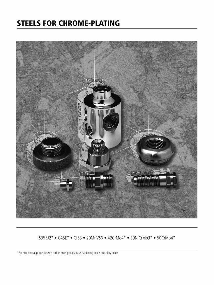
STEELS FOR CHROME-PLATING
* For mechanical properties see carbon steel groups, case-hardening steels and alloy steels
S355J2* • C45E* • Cf53 • 20MnVS6 • 42CrMo4* • 39NiCrMo3* • 50CrMo4*
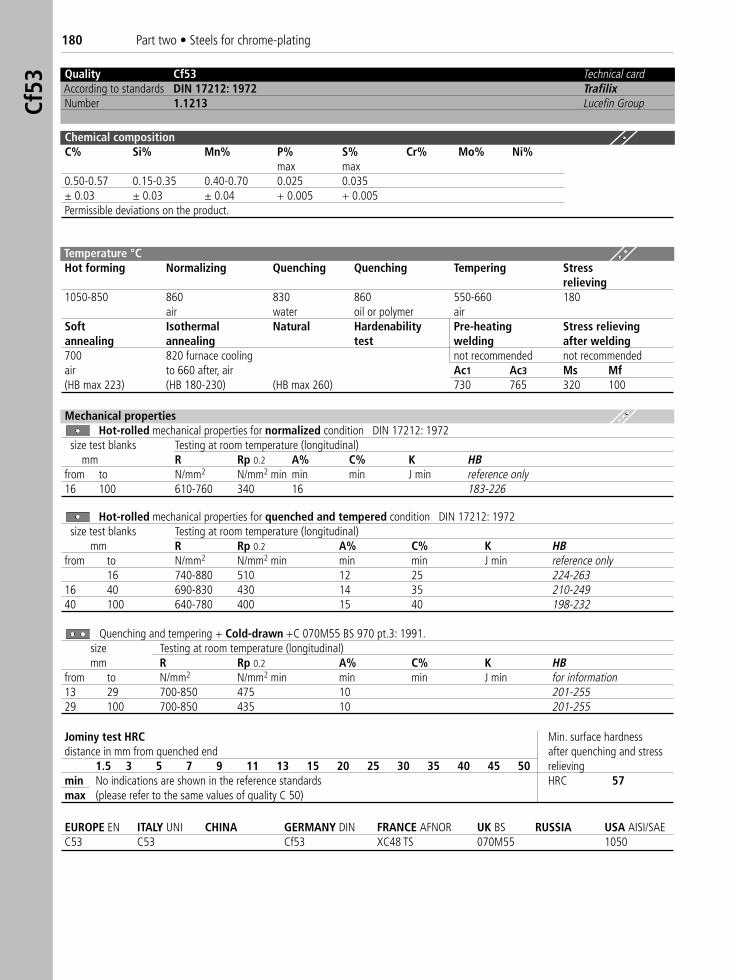
180 Part two • Steels for chrome-platingCf
53
Quality Cf53 Technical cardAccording to standards DIN 17212: 1972 TrafilixNumber 1.1213 Lucefin Group
Chemical compositionC% Si% Mn% P% S% Cr% Mo% Ni%
max max0.50-0.57 0.15-0.35 0.40-0.70 0.025 0.035± 0.03 ± 0.03 ± 0.04 + 0.005 + 0.005Permissible deviations on the product.
Temperature °C Hot forming Normalizing Quenching Quenching Tempering Stress
relieving1050-850 860 830 860 550-660 180
air water oil or polymer airSoft Isothermal Natural Hardenability Pre-heating Stress relievingannealing annealing test welding after welding700 820 furnace cooling not recommended not recommendedair to 660 after, air Ac1 Ac3 Ms Mf(HB max 223) (HB 180-230) (HB max 260) 730 765 320 100
Mechanical propertiesHot-rolled mechanical properties for normalized condition DIN 17212: 1972
size test blanks Testing at room temperature (longitudinal)mm R Rp 0.2 A% C% K HB
from to N/mm2 N/mm2 min min min J min reference only16 100 610-760 340 16 183-226
Hot-rolled mechanical properties for quenched and tempered condition DIN 17212: 1972size test blanks Testing at room temperature (longitudinal)
mm R Rp 0.2 A% C% K HBfrom to N/mm2 N/mm2 min min min J min reference only
16 740-880 510 12 25 224-26316 40 690-830 430 14 35 210-24940 100 640-780 400 15 40 198-232
Quenching and tempering + Cold-drawn +C 070M55 BS 970 pt.3: 1991.size Testing at room temperature (longitudinal)mm R Rp 0.2 A% C% K HB
from to N/mm2 N/mm2 min min min J min for information13 29 700-850 475 10 201-25529 100 700-850 435 10 201-255
Jominy test HRC Min. surface hardness distance in mm from quenched end after quenching and stress
1.5 3 5 7 9 11 13 15 20 25 30 35 40 45 50 relievingmin No indications are shown in the reference standards HRC 57max (please refer to the same values of quality C 50)
EUROPE EN ITALY UNI CHINA GERMANY DIN FRANCE AFNOR UK BS RUSSIA USA AISI/SAEC53 C53 Cf53 XC48 TS 070M55 1050
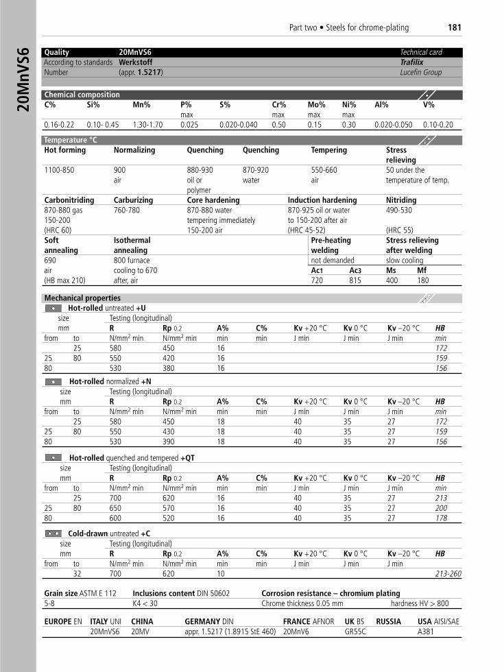
Part two • Steels for chrome-plating 18120
MnV
S6 Quality 20MnVS6 Technical cardAccording to standards Werkstoff TrafilixNumber (appr. 1.5217) Lucefin Group
Chemical compositionC% Si% Mn% P% S% Cr% Mo% Ni% Al% V%
max max max max0.16-0.22 0.10- 0.45 1.30-1.70 0.025 0.020-0.040 0.50 0.15 0.30 0.020-0.050 0.10-0.20
Temperature °C Hot forming Normalizing Quenching Quenching Tempering Stress
relieving1100-850 900 880-930 870-920 550-660 50 under the
air oil or water air temperature of temp.polymer
Carbonitriding Carburizing Core hardening Induction hardening Nitriding870-880 gas 760-780 870-880 water 870-925 oil or water 490-530150-200 tempering immediately to 150-200 after air(HRC 60) 150-200 air (HRC 45-52) (HRC 55)Soft Isothermal Pre-heating Stress relievingannealing annealing welding after welding690 800 furnace not demanded slow coolingair cooling to 670 Ac1 Ac3 Ms Mf(HB max 210) after, air 720 815 400 180
Mechanical propertiesHot-rolled untreated +U �
size Testing (longitudinal)mm R Rp 0.2 A% C% Kv +20 °C Kv 0 °C Kv –20 °C HB
from to N/mm2 min N/mm2 min min min J min J min J min min25 580 450 16 172
25 80 550 420 16 15980 530 380 16 156
Hot-rolled normalized +N �size Testing (longitudinal)mm R Rp 0.2 A% C% Kv +20 °C Kv 0 °C Kv –20 °C HB
from to N/mm2 min N/mm2 min min min J min J min J min min25 580 450 18 40 35 27 172
25 80 550 430 18 40 35 27 15980 530 390 18 40 35 27 156
Hot-rolled quenched and tempered +QT �size Testing (longitudinal)mm R Rp 0.2 A% C% Kv +20 °C Kv 0 °C Kv –20 °C HB
from to N/mm2 min N/mm2 min min min J min J min J min min25 700 620 16 40 35 27 213
25 80 650 570 16 40 35 27 20080 600 520 16 40 35 27 178
Cold-drawn untreated +C �size Testing (longitudinal) mm R Rp 0.2 A% C% Kv +20 °C Kv 0 °C Kv –20 °C HB
from to N/mm2 min N/mm2 min min min J min J min J min32 700 620 10 213-260
Grain size ASTM E 112 Inclusions content DIN 50602 Corrosion resistance – chromium plating5-8 K4 < 30 Chrome thickness 0.05 mm hardness HV > 800
EUROPE EN ITALY UNI CHINA GERMANY DIN FRANCE AFNOR UK BS RUSSIA USA AISI/SAE 20MnVS6 20MV appr. 1.5217 (1.8915 StE 460) 20MnV6 GR55C A381
STRUCTURAL AND CONSTRUCTIONAL STEELS
SAE 1141 • SAE 1116 • SAE 1117 • SAE 1018 • SAE 1045 CB 4 FF • CB 20 FF • C20
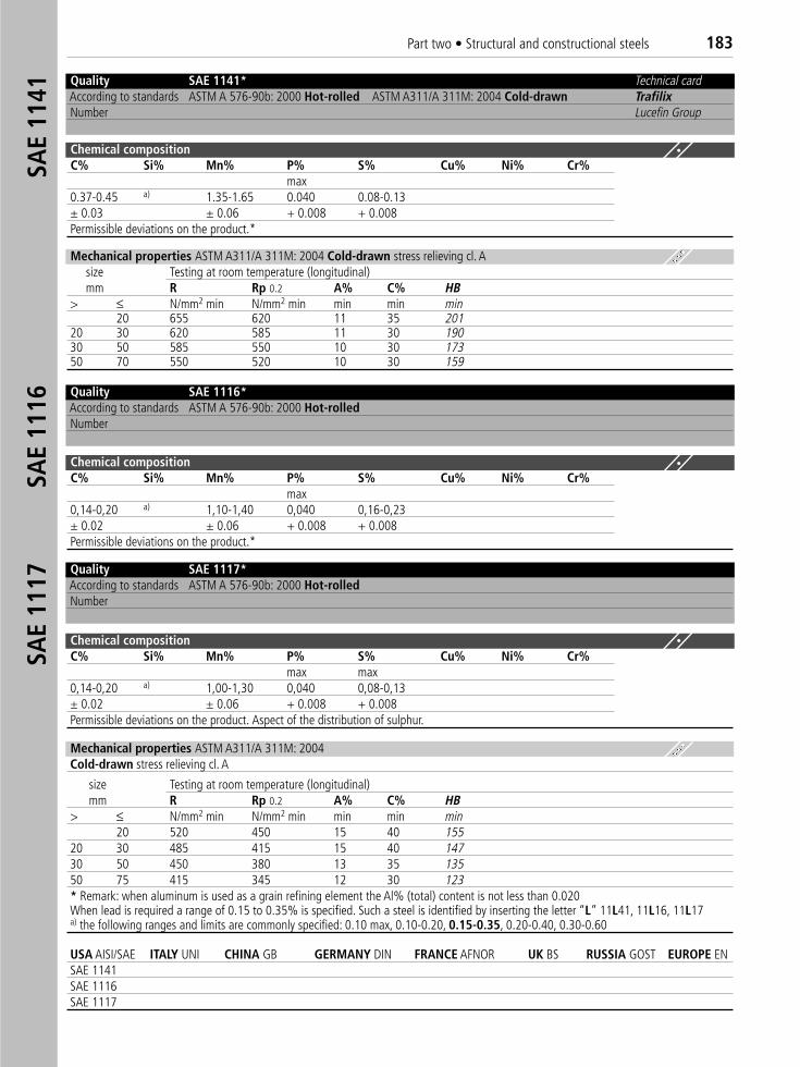
Part two • Structural and constructional steels 183SA
E 11
41SA
E 11
16SA
E 11
17
Quality SAE 1141* Technical cardAccording to standards ASTM A 576-90b: 2000 Hot-rolled ASTM A311/A 311M: 2004 Cold-drawn TrafilixNumber Lucefin Group
Chemical compositionC% Si% Mn% P% S% Cu% Ni% Cr%
max0.37-0.45 a) 1.35-1.65 0.040 0.08-0.13± 0.03 ± 0.06 + 0.008 + 0.008Permissible deviations on the product.*
Mechanical properties ASTM A311/A 311M: 2004 Cold-drawn stress relieving cl. Asize Testing at room temperature (longitudinal)mm R Rp 0.2 A% C% HB
> ≤ N/mm2 min N/mm2 min min min min20 655 620 11 35 201
20 30 620 585 11 30 19030 50 585 550 10 30 17350 70 550 520 10 30 159
Quality SAE 1117* According to standards ASTM A 576-90b: 2000 Hot-rolledNumber
Chemical compositionC% Si% Mn% P% S% Cu% Ni% Cr%
max max0,14-0,20 a) 1,00-1,30 0,040 0,08-0,13± 0.02 ± 0.06 + 0.008 + 0.008Permissible deviations on the product. Aspect of the distribution of sulphur.
Mechanical properties ASTM A311/A 311M: 2004 Cold-drawn stress relieving cl. A
size Testing at room temperature (longitudinal)mm R Rp 0.2 A% C% HB
> ≤ N/mm2 min N/mm2 min min min min20 520 450 15 40 155
20 30 485 415 15 40 14730 50 450 380 13 35 13550 75 415 345 12 30 123* Remark: when aluminum is used as a grain refining element the Al% (total) content is not less than 0.020When lead is required a range of 0.15 to 0.35% is specified. Such a steel is identified by inserting the letter “L” 11L41, 11L16, 11L17a) the following ranges and limits are commonly specified: 0.10 max, 0.10-0.20, 0.15-0.35, 0.20-0.40, 0.30-0.60
Quality SAE 1116*According to standards ASTM A 576-90b: 2000 Hot-rolledNumber
Chemical compositionC% Si% Mn% P% S% Cu% Ni% Cr%
max0,14-0,20 a) 1,10-1,40 0,040 0,16-0,23± 0.02 ± 0.06 + 0.008 + 0.008Permissible deviations on the product.*
USA AISI/SAE ITALY UNI CHINA GB GERMANY DIN FRANCE AFNOR UK BS RUSSIA GOST EUROPE ENSAE 1141SAE 1116SAE 1117
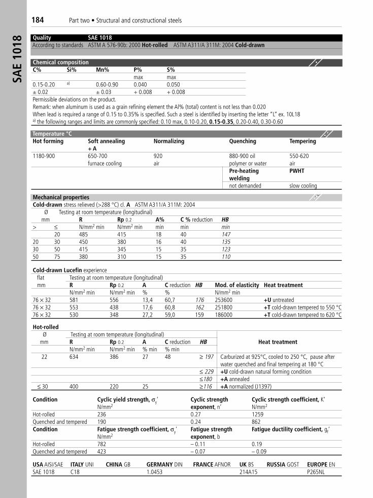
184 Part two • Structural and constructional steelsSA
E 10
18
Condition Cyclic yield strength, σy’ Cyclic strength Cyclic strength coefficient, K‘N/mm2 exponent, n’ N/mm2
Hot-rolled 236 0.27 1259Quenched and tempered 190 0.24 862Condition Fatigue strength coefficient, σy’ Fatigue strength Fatigue ductility coefficient, gf‘
N/mm2 exponent, bHot-rolled 782 – 0.11 0.19Quenched and tempered 423 – 0.07 – 0.09
USA AISI/SAE ITALY UNI CHINA GB GERMANY DIN FRANCE AFNOR UK BS RUSSIA GOST EUROPE ENSAE 1018 C18 1.0453 214A15 P265NL
Quality SAE 1018 According to standards ASTM A 576-90b: 2000 Hot-rolled ASTM A311/A 311M: 2004 Cold-drawn
Chemical compositionC% Si% Mn% P% S%
max max0.15-0.20 a) 0.60-0.90 0.040 0.050± 0.02 ± 0.03 + 0.008 + 0.008Permissible deviations on the product.Remark: when aluminum is used as a grain refining element the Al% (total) content is not less than 0.020 When lead is required a range of 0.15 to 0.35% is specified. Such a steel is identified by inserting the letter “L” ex. 10L18a) the following ranges and limits are commonly specified: 0.10 max, 0.10-0.20, 0.15-0.35, 0.20-0.40, 0.30-0.60
Mechanical propertiesCold-drawn stress relieved (>288 °C) cl. A ASTM A311/A 311M: 2004
Ø Testing at room temperature (longitudinal)mm R Rp 0.2 A% C % reduction HB
> ≤ N/mm2 min N/mm2 min min min min20 485 415 18 40 147
20 30 450 380 16 40 13530 50 415 345 15 35 12350 75 380 310 15 35 110
Cold-drawn Lucefin experienceflat Testing at room temperature (longitudinal)mm R Rp 0.2 A C reduction HB Mod. of elasticity Heat treatment
N/mm2 min N/mm2 min % % N/mm2 min76 × 32 581 556 13,4 60,7 176 253600 +U untreated76 × 32 553 438 17,6 60,8 162 251800 +T cold-drawn tempered to 550 °C76 × 32 530 348 27,2 59,0 159 186000 +T cold-drawn tempered to 620 °C
Hot-rolledØ Testing at room temperature (longitudinal)
mm R Rp 0.2 A C reduction HB Heat treatmentN/mm2 min N/mm2 min % min % min
22 634 386 27 48 ≥ 197 Carburized at 925°C, cooled to 250 °C, pause after water quenched and final tempering at 180 °C
≤ 229 +U cold-drawn natural forming condition≤180 +A annealed
≤ 30 400 220 25 ≥116 +A normalized (J1397)
Temperature °C Hot forming Soft annealing Normalizing Quenching Tempering
+ A1180-900 650-700 920 880-900 oil 550-620
furnace cooling air polymer or water airPre-heating PWHTweldingnot demanded slow cooling
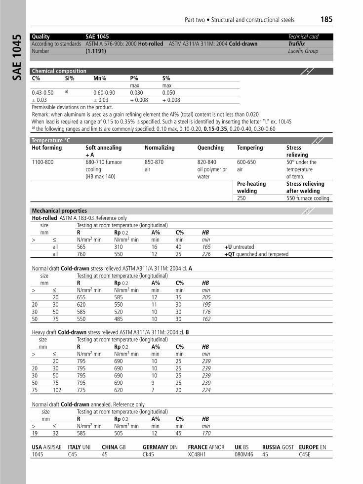
Part two • Structural and constructional steels 185SA
E 10
45
USA AISI/SAE ITALY UNI CHINA GB GERMANY DIN FRANCE AFNOR UK BS RUSSIA GOST EUROPE EN1045 C45 45 Ck45 XC48H1 080M46 45 C45E
Quality SAE 1045 Technical cardAccording to standards ASTM A 576-90b: 2000 Hot-rolled ASTM A311/A 311M: 2004 Cold-drawn TrafilixNumber (1.1191) Lucefin Group
Chemical compositionC% Si% Mn% P% S%
max max0.43-0.50 a) 0.60-0.90 0.030 0.050± 0.03 ± 0.03 + 0.008 + 0.008Permissible deviations on the product.Remark: when aluminum is used as a grain refining element the Al% (total) content is not less than 0.020When lead is required a range of 0.15 to 0.35% is specified. Such a steel is identified by inserting the letter “L” ex. 10L4Sa) the following ranges and limits are commonly specified: 0.10 max, 0.10-0.20, 0.15-0.35, 0.20-0.40, 0.30-0.60
Mechanical propertiesHot-rolled ASTM A 183-03 Reference only
size Testing at room temperature (longitudinal)mm R Rp 0.2 A% C% HB
> ≤ N/mm2 min N/mm2 min min min minall 565 310 16 40 165 +U untreatedall 760 550 12 25 226 +QT quenched and tempered
Normal draft Cold-drawn stress relieved ASTM A311/A 311M: 2004 cl. Asize Testing at room temperature (longitudinal)mm R Rp 0.2 A% C% HB
> ≤ N/mm2 min N/mm2 min min min min20 655 585 12 35 205
20 30 620 550 11 30 19530 50 585 520 10 30 17650 75 550 485 10 30 162
Heavy draft Cold-drawn stress relieved ASTM A311/A 311M: 2004 cl. Bsize Testing at room temperature (longitudinal)mm R Rp 0.2 A% C% HB
> ≤ N/mm2 min N/mm2 min min min min20 795 690 10 25 239
20 30 795 690 10 25 23930 50 795 690 10 25 23950 75 795 690 9 25 23975 102 725 620 7 20 224
Normal draft Cold-drawn annealed. Reference onlysize Testing at room temperature (longitudinal)mm R Rp 0.2 A% C% HB
> ≤ N/mm2 min N/mm2 min min min min19 32 585 505 12 45 170
Temperature °C Hot forming Soft annealing Normalizing Quenching Tempering Stress
+ A relieving1100-800 680-710 furnace 850-870 820-840 600-650 50° under the
cooling air oil polymer or air temperature(HB max 140) water of temp.
Pre-heating Stress relievingwelding after welding250 550 furnace cooling
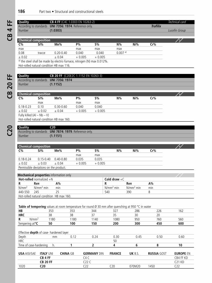
186 Part two • Structural and constructional steelsCB
4 F
FCB
20
FFC2
0
Quality CB 4 FF (C4C 1.0303 EN 10263-2) Technical cardAccording to standards UNI 7356: 1974. Reference only. TrafilixNumber (1.0303) Lucefin Group
Chemical compositionC% Si% Mn% P% S% N% Ni% Cr%max max max max0.08 tracce 0.20-0.40 0.040 0.040 0.007 a)
± 0.02 ± 0.04 + 0.005 + 0.005a) the steel shall be made by electric-furnace, nitrogen (N) max 0.012%.Hot-rolled natural condition HB max 116.
Quality CB 20 FF ((C20E2C 1.1152 EN 10263-3)According to standards UNI 7356: 1974Number (1.1152)
Chemical compositionC% Si% Mn% P% S% N% Ni% Cr%
max max max0.18-0.23 0.10 0.30-0.60 0.040 0.040± 0.02 ± 0.02 ± 0.04 + 0.005 + 0.005Fully killed (Al – Nb – V)Hot-rolled natural condition HB max 160.
Quality C20According to standards UNI 7874: 1979. Reference only.Number (1.1151)
Chemical compositionC% Si% Mn% P% S% N% Ni% Cr%
max max0.18-0.24 0.15-0.40 0.40-0.80 0.035 0.035± 0.02 ± 0.03 ± 0.04 + 0.005 + 0.005Permissible deviations on the product.
Mechanical properties information onlyHot-rolled normalized +N Cold draw +CR ReH A% R ReH A%N/mm2 N/mm2 min min N/mm2 min N/mm2 min min440-550 245 25 540 390 8Hot-rolled natural condition HB max 160.
Table of tempering values at room temperature for round Ø 30 mm after quenching at 950 °C in waterHB 353 353 344 327 286 226 162HRC 38 38 37 35 30 20R N/mm2 1180 1180 1140 1080 950 760 560Tempering at°C 50 100 150 200 300 450 600
Effective depth of case- hardened layerDepth mm 0.12 0.24 0.30 0.45 0.50 0.60HRC 50Time of case-hardening h. 1 2 4 6 8 10
USA AISI/SAE ITALY UNI CHINA GB GERMANY DIN FRANCE UK B.S. RUSSIA GOST EUROPE ENCB 4 FF C4 C CB4 FF KDCB 20 FF C22 C C21 KD
1020 C20 C22 C20 070M20 1450 C22
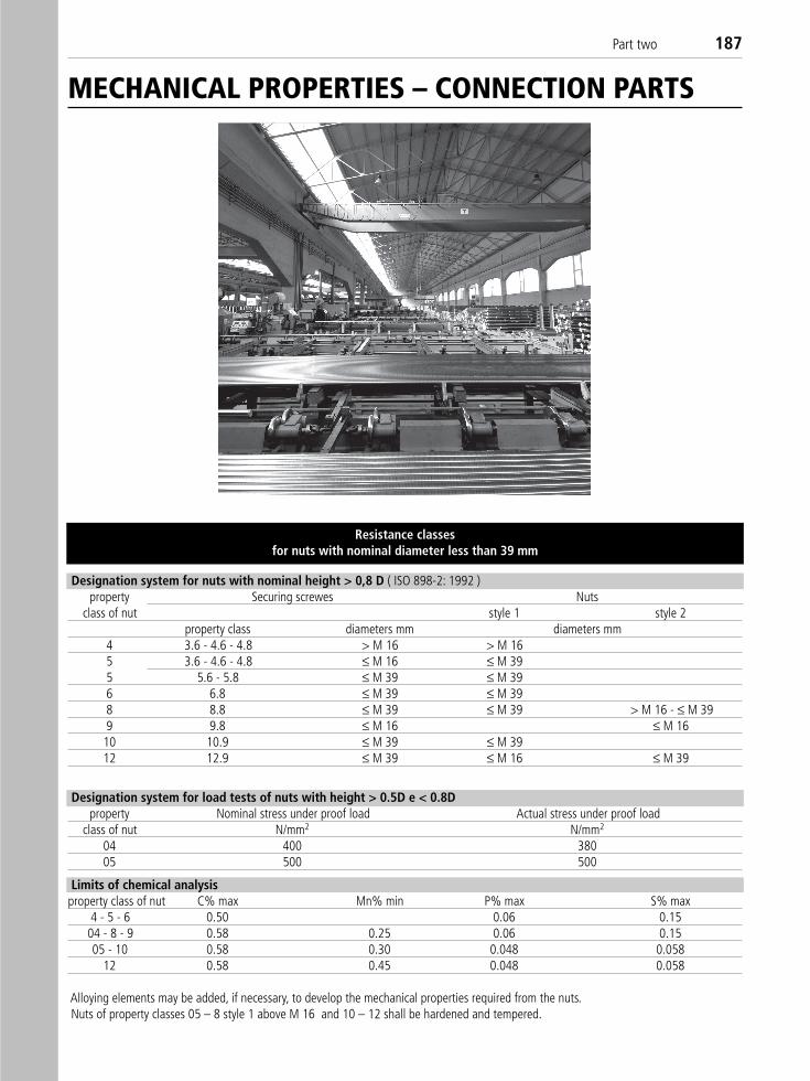
Part two 187
Resistance classesfor nuts with nominal diameter less than 39 mm
Designation system for load tests of nuts with height > 0.5D e < 0.8Dproperty Nominal stress under proof load Actual stress under proof load
class of nut N/mm2 N/mm2
04 400 38005 500 500
Limits of chemical analysisproperty class of nut C% max Mn% min P% max S% max
4 - 5 - 6 0.50 0.06 0.1504 - 8 - 9 0.58 0.25 0.06 0.1505 - 10 0.58 0.30 0.048 0.058
12 0.58 0.45 0.048 0.058
Alloying elements may be added, if necessary, to develop the mechanical properties required from the nuts.Nuts of property classes 05 – 8 style 1 above M 16 and 10 – 12 shall be hardened and tempered.
MECHANICAL PROPERTIES – CONNECTION PARTS
Designation system for nuts with nominal height > 0,8 D ( ISO 898-2: 1992 )property Securing screwes Nuts
class of nut style 1 style 2property class diameters mm diameters mm
4 3.6 - 4.6 - 4.8 > M 16 > M 165 3.6 - 4.6 - 4.8 ≤ M 16 ≤ M 395 5.6 - 5.8 ≤ M 39 ≤ M 396 6.8 ≤ M 39 ≤ M 398 8.8 ≤ M 39 ≤ M 39 > M 16 - ≤ M 399 9.8 ≤ M 16 ≤ M 1610 10.9 ≤ M 39 ≤ M 3912 12.9 ≤ M 39 ≤ M 16 ≤ M 39
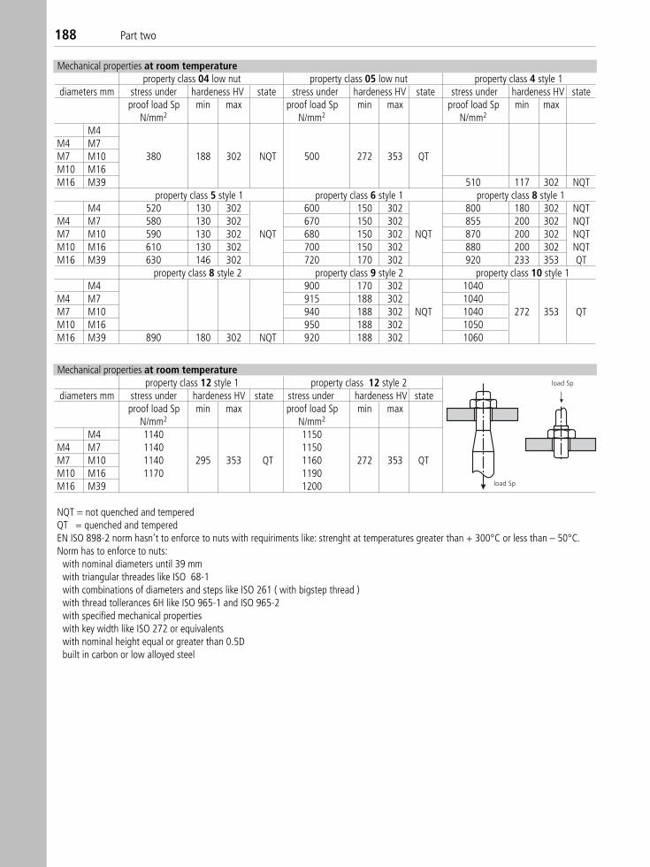
188 Part two
Mechanical properties at room temperatureproperty class 04 low nut property class 05 low nut property class 4 style 1
diameters mm stress under hardeness HV state stress under hardeness HV state stress under hardeness HV stateproof load Sp min max proof load Sp min max proof load Sp min max
N/mm2 N/mm2 N/mm2
M4M4 M7M7 M10 380 188 302 NQT 500 272 353 QTM10 M16M16 M39 510 117 302 NQT
property class 5 style 1 property class 6 style 1 property class 8 style 1M4 520 130 302 600 150 302 800 180 302 NQT
M4 M7 580 130 302 670 150 302 855 200 302 NQTM7 M10 590 130 302 NQT 680 150 302 NQT 870 200 302 NQTM10 M16 610 130 302 700 150 302 880 200 302 NQTM16 M39 630 146 302 720 170 302 920 233 353 QT
property class 8 style 2 property class 9 style 2 property class 10 style 1M4 900 170 302 1040
M4 M7 915 188 302 1040M7 M10 940 188 302 NQT 1040 272 353 QTM10 M16 950 188 302 1050M16 M39 890 180 302 NQT 920 188 302 1060
Mechanical properties at room temperatureproperty class 12 style 1 property class 12 style 2
diameters mm stress under hardeness HV state stress under hardeness HV stateproof load Sp min max proof load Sp min max
N/mm2 N/mm2
M4 1140 1150M4 M7 1140 1150M7 M10 1140 295 353 QT 1160 272 353 QTM10 M16 1170 1190M16 M39 1200
NQT = not quenched and temperedQT = quenched and temperedEN ISO 898-2 norm hasn’t to enforce to nuts with requiriments like: strenght at temperatures greater than + 300°C or less than – 50°C.Norm has to enforce to nuts:
with nominal diameters until 39 mmwith triangular threades like ISO 68-1with combinations of diameters and steps like ISO 261 ( with bigstep thread )with thread tollerances 6H like ISO 965-1 and ISO 965-2with specified mechanical propertieswith key width like ISO 272 or equivalentswith nominal height equal or greater than 0.5Dbuilt in carbon or low alloyed steel
load Sp
load Sp
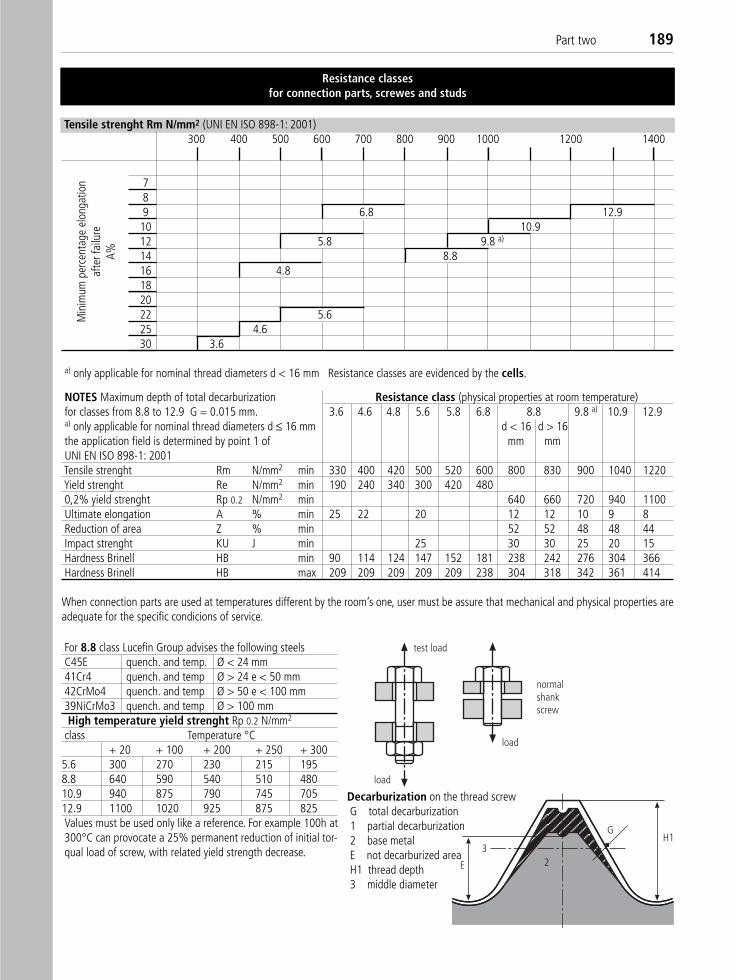
Part two 189
Resistance classesfor connection parts, screwes and studs
Tensile strenght Rm N/mm2 (UNI EN ISO 898-1: 2001)300 400 500 600 700 800 900 1000 1200 1400
789 6.8 12.910 10.912 5.8 9.8 a)
14 8.816 4.8182022 5.625 4.630 3.6
a) only applicable for nominal thread diameters d < 16 mm Resistance classes are evidenced by the cells.
Min
imum
per
cent
age
elon
gatio
naf
ter f
ailu
reA%
NOTES Maximum depth of total decarburization Resistance class (physical properties at room temperature)for classes from 8.8 to 12.9 G = 0.015 mm. 3.6 4.6 4.8 5.6 5.8 6.8 8.8 9.8 a) 10.9 12.9a) only applicable for nominal thread diameters d ≤ 16 mm d < 16 d > 16the application field is determined by point 1 of mm mmUNI EN ISO 898-1: 2001Tensile strenght Rm N/mm2 min 330 400 420 500 520 600 800 830 900 1040 1220Yield strenght Re N/mm2 min 190 240 340 300 420 4800,2% yield strenght Rp 0.2 N/mm2 min 640 660 720 940 1100Ultimate elongation A % min 25 22 20 12 12 10 9 8Reduction of area Z % min 52 52 48 48 44Impact strenght KU J min 25 30 30 25 20 15Hardness Brinell HB min 90 114 124 147 152 181 238 242 276 304 366Hardness Brinell HB max 209 209 209 209 209 238 304 318 342 361 414
When connection parts are used at temperatures different by the room’s one, user must be assure that mechanical and physical properties areadequate for the specific condicions of service.
For 8.8 class Lucefin Group advises the following steelsC45E quench. and temp. Ø < 24 mm41Cr4 quench. and temp Ø > 24 e < 50 mm42CrMo4 quench. and temp Ø > 50 e < 100 mm39NiCrMo3 quench. and temp Ø > 100 mmHigh temperature yield strenght Rp 0.2 N/mm2
class Temperature °C+ 20 + 100 + 200 + 250 + 300
5.6 300 270 230 215 1958.8 640 590 540 510 48010.9 940 875 790 745 70512.9 1100 1020 925 875 825Values must be used only like a reference. For example 100h at300°C can provocate a 25% permanent reduction of initial tor-qual load of screw, with related yield strength decrease.
test load
load
load
normalshankscrew
E
3
GH1
2
Decarburization on the thread screwG total decarburization1 partial decarburization2 base metalE not decarburized areaH1 thread depth3 middle diameter
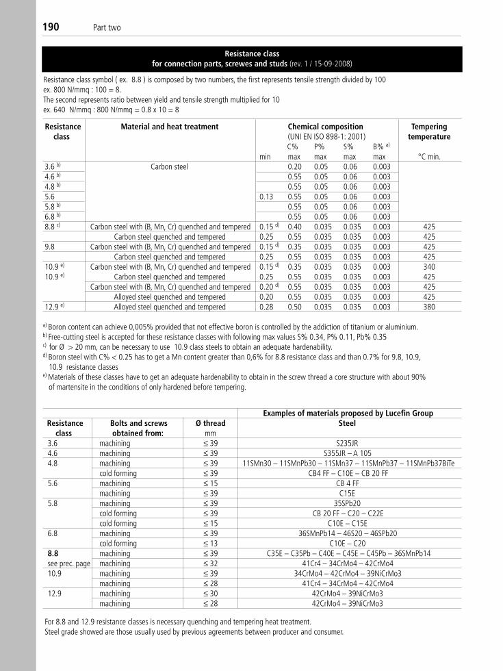
190 Part two
Resistance class symbol ( ex. 8.8 ) is composed by two numbers, the first represents tensile strength divided by 100ex. 800 N/mmq : 100 = 8. The second represents ratio between yield and tensile strength multiplied for 10ex. 640 N/mmq : 800 N/mmq = 0.8 x 10 = 8
Resistance classfor connection parts, screwes and studs (rev. 1 / 15-09-2008)
Resistance Material and heat treatment Chemical composition Temperingclass (UNI EN ISO 898-1: 2001) temperature
C% P% S% B% a)
min max max max max °C min.3.6 b) Carbon steel 0.20 0.05 0.06 0.0034.6 b) 0.55 0.05 0.06 0.0034.8 b) 0.55 0.05 0.06 0.0035.6 0.13 0.55 0.05 0.06 0.0035.8 b) 0.55 0.05 0.06 0.0036.8 b) 0.55 0.05 0.06 0.0038.8 c) Carbon steel with (B, Mn, Cr) quenched and tempered 0.15 d) 0.40 0.035 0.035 0.003 425
Carbon steel quenched and tempered 0.25 0.55 0.035 0.035 0.003 4259.8 Carbon steel with (B, Mn, Cr) quenched and tempered 0.15 d) 0.35 0.035 0.035 0.003 425
Carbon steel quenched and tempered 0.25 0.55 0.035 0.035 0.003 42510.9 e) Carbon steel with (B, Mn, Cr) quenched and tempered 0.15 d) 0.35 0.035 0.035 0.003 34010.9 e) Carbon steel quenched and tempered 0.25 0.55 0.035 0.035 0.003 425
Carbon steel with (B, Mn, Cr) quenched and tempered 0.20 d) 0.55 0.035 0.035 0.003 425Alloyed steel quenched and tempered 0.20 0.55 0.035 0.035 0.003 425
12.9 e) Alloyed steel quenched and tempered 0.28 0.50 0.035 0.035 0.003 380
a) Boron content can achieve 0,005% provided that not effective boron is controlled by the addiction of titanium or aluminium.b) Free-cutting steel is accepted for these resistance classes with following max values S% 0.34, P% 0.11, Pb% 0.35c) for Ø > 20 mm, can be necessary to use 10.9 class steels to obtain an adequate hardenability.d) Boron steel with C% < 0.25 has to get a Mn content greater than 0,6% for 8.8 resistance class and than 0.7% for 9.8, 10.9,
10.9 resistance classese) Materials of these classes have to get an adequate hardenability to obtain in the screw thread a core structure with about 90%
of martensite in the conditions of only hardened before tempering.
Examples of materials proposed by Lucefin GroupResistance Bolts and screws Ø thread Steel
class obtained from: mm3.6 machining ≤ 39 S235JR4.6 machining ≤ 39 S355JR – A 1054.8 machining ≤ 39 11SMn30 – 11SMnPb30 – 11SMn37 – 11SMnPb37 – 11SMnPb37BiTe
cold forming ≤ 39 CB4 FF – C10E – CB 20 FF5.6 machining ≤ 15 CB 4 FF
machining ≤ 39 C15E5.8 machining ≤ 39 35SPb20
cold forming ≤ 39 CB 20 FF – C20 – C22Ecold forming ≤ 15 C10E – C15E
6.8 machining ≤ 39 36SMnPb14 – 46S20 – 46SPb20cold forming ≤ 13 C10E – C20
8.8 machining ≤ 39 C35E – C35Pb – C40E – C45E – C45Pb – 36SMnPb14see prec. page machining ≤ 32 41Cr4 – 34CrMo4 – 42CrMo4 10.9 machining ≤ 39 34CrMo4 – 42CrMo4 – 39NiCrMo3
machining ≤ 28 41Cr4 – 34CrMo4 – 42CrMo4 12.9 machining ≤ 30 42CrMo4 – 39NiCrMo3
machining ≤ 28 42CrMo4 – 39NiCrMo3
For 8.8 and 12.9 resistance classes is necessary quenching and tempering heat treatment.Steel grade showed are those usually used by previous agreements between producer and consumer.
Part three
Technical tables
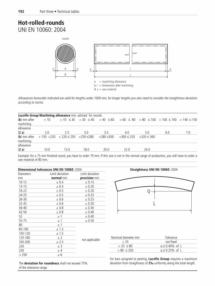
192 Part three • Technical tables
Dimensional tolerances UNI EN 10060: 2004Diameters Limit deviation Limit deviationmm normal mm precision mm10-12 ± 0.4 ± 0.1513-15 ± 0.4 ± 0.2016-22 ± 0.5 ± 0.2024-25 ± 0.5 ± 0.2526-30 ± 0.6 ± 0.2532-35 ± 0.6 ± 0.3036-40 ± 0.8 ± 0.3042-50 ± 0.8 ± 0.4052 ± 1 ± 0.4055-75 ± 1 ± 0.5080 ± 185-100 ± 1.3105-120 ± 1.5125-160 ± 2165-200 ± 2.5220 ± 3250 ± 4> 250 ± 6
The deviation for roundness shall not exceed 75% of the tolerance range.
Lucefin Group Machining allowance min. advised for rounds(b) mm after < 10 > 10 ≤ 30 > 30 ≤ 40 > 40 ≤ 60 > 60 ≤ 80 > 80 ≤ 100 > 100 ≤ 140 > 140 ≤ 150machiningallowance(2 a) 2.0 2.5 3.0 3.5 4.0 5.0 6.0 7.0(b) mm after > 150 <220 > 220 ≤ 250 >250 ≤280 >280 ≤300 >300 ≤ 320 >320 ≤ 360machiningallowance(2 a) 10.0 13.0 18.0 20.0 22.0 24.0
Example: for a 75 mm finished round, you have to order 79 mm. If this size is not in the normal range of production, you will have to order araw material of 80 mm.
a = machining allowanceb, l = dimensions after machiningB, L = raw material
a al
L
a b
B
a
round
Allowances hereunder indicated are valid for lengths under 1000 mm, for longer lengths you also need to consider the straightness deviationaccording to norms.
not applicable
Straightness UNI EN 10060: 2004
q
L
Nominal diameter mm Tolerance< 25 not fixed
> 25 ≤ 80 q ≤ 0.40% of L> 80 ≤ 250 q ≤ 0.25% of L
For bars assigned to peeling, Lucefin Group requires a maximumdeviation from straightness of 2‰ uniformly along the total length.
Hot-rolled-roundsUNI EN 10060: 2004
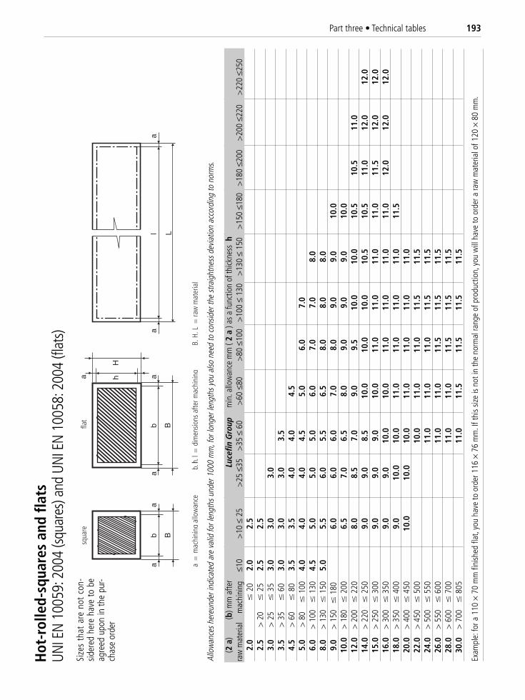
Part three • Technical tables 193
squa
refla
t
am
achi
ning
allo
wan
ceb,
h, l l
=di
men
sions
afte
r mac
hini
ngB,
H, L
=ra
w m
ater
ial
=
Allo
wan
ces h
ereu
nder
indi
cate
d ar
e va
lid fo
r len
gths
und
er 1
000
mm
, for
long
er le
ngth
s you
also
nee
d to
con
sider
the
stra
ight
ness
dev
iatio
n ac
cord
ing
to n
orm
s.
(2 a
)(b
) mm
afte
rLu
cefin
Gro
upm
in. a
llow
ance
mm
( 2
a) a
s a
func
tion
of th
ickne
ssh
raw
mat
eria
lm
achi
ning
≤10
>10
≤ 2
5>
25 ≤
35>
35 ≤
60
>60
≤80
>80
≤10
0 >
100
≤ 13
0>
130
≤ 15
0>
150
≤180
>18
0 ≤2
00>
200
≤220
>22
0 ≤2
502.
0�
20
2.0
2.5
2.5
> 2
0�
252.
52.
53.
0>
25
�35
3.0
3.0
3.0
3.5
> 3
5�
603.
03.
03.
03.
54.
5>
60
�80
3.5
3.5
4.0
4.0
4.5
5.0
> 8
0�
100
4.0
4.0
4.0
4.5
5.0
6.0
7.0
6.0
> 1
00�
130
4.5
5.0
5.0
5.0
6.0
7.0
7.0
8.0
8.0
> 1
30�
150
5.0
5.5
6.0
5.5
6.5
8.0
8.0
8.0
9.0
> 1
50�
180
6.0
6.0
6.0
7.0
8.0
9.0
9.0
10.0
10.0
> 1
80�
200
6.5
7.0
6.5
8.0
9.0
9.0
9.0
10.0
12.0
> 2
00�
220
8.0
8.5
7.0
9.0
9.5
10.0
10.0
10.5
10.5
11.0
14.0
> 2
20�
250
9.0
9.0
8.5
10.0
10.0
10.0
10.5
10.5
11.0
12.0
12.0
15.0
> 2
50�
300
9.0
9.0
9.0
10.0
11.0
11.0
11.0
11.0
11.5
12.0
12.0
16.0
> 3
00�
350
9.0
9.0
10.0
10.0
11.0
11.0
11.0
11.0
12.0
12.0
12.0
18.0
> 3
50�
400
9.0
10.0
10.0
11.0
11.0
11.0
11.0
11.5
20.0
> 4
00�
450
10.0
10.0
10.0
11.0
11.0
11.0
11.0
22.0
> 4
50�
500
10.0
11.0
11.0
11.5
11.5
24.0
> 5
00�
550
11.0
11.0
11.0
11.5
11.5
26.0
> 5
50�
600
11.0
11.0
11.5
11.5
11.5
28.0
> 6
00�
700
11.0
11.0
11.5
11.5
11.5
30.0
> 7
00�
805
11.0
11.5
11.5
11.5
11.5
Exam
ple:
for a
110
×70
mm
fini
shed
flat
, you
hav
e to
ord
er 1
16 ×
76 m
m. I
f thi
s siz
e is
not i
n th
e no
rmal
rang
e of
pro
duct
ion,
you
will
hav
e to
ord
er a
raw
mat
eria
l of 1
20 ×
80 m
m.
Hot
-rol
led-
squa
res
and
flats
UNI E
N 10
059:
200
4 (sq
uare
s) an
d UN
I EN
1005
8: 2
004
(flat
s)Si
zes
that
are
not
con
-sid
ered
her
e ha
ve to
be
agre
ed u
pon
in th
e pu
r-ch
ase
orde
r
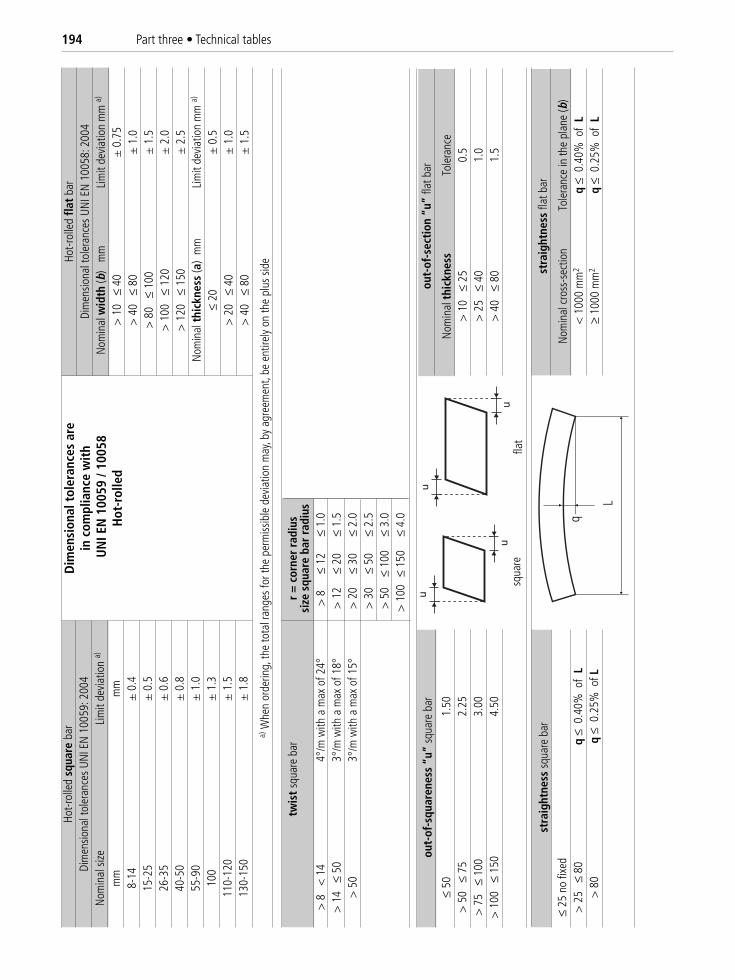
194 Part three • Technical tables
�
�
q
L
u
u
a)W
hen
orde
ring,
the
tota
l ran
ges
for t
he p
erm
issib
le d
evia
tion
may
, by
agre
emen
t, be
ent
irely
on th
e pl
us s
ide
twis
t sq
uare
bar
r =
cor
ner
radi
ussi
zesq
uare
bar
rad
ius
> 8
<
14
4°/m
with
a m
ax o
f24°
> 8
≤ 12
≤ 1.
0>
14
≤ 5
03°
/m w
ith a
max
of1
8°>
12
≤ 20
≤ 1.
5>
50
3°/m
with
a m
ax o
f15°
> 2
0≤
30≤
2.0
> 3
0≤
50≤
2.5
> 5
0≤
100
≤ 3.
0>
100
≤ 15
0≤
4.0
Dim
ensi
onal
tol
eran
ces
are
in c
ompl
ianc
e w
ith
UN
I EN
100
59 /
1005
8H
ot-r
olle
d
Hot-r
olle
dsq
uare
bar
Dim
ensio
nal t
oler
ance
sUN
I EN
100
59: 2
004
Nom
inal
size
Lim
it de
viat
ion
a)
mm
mm
8-14
± 0
.415
-25
± 0
.526
-35
± 0
.640
-50
± 0
.855
-90
± 1
.010
0±
1.3
110-
120
± 1
.513
0-15
0±
1.8
Hot-r
olle
dfla
t ba
rDi
men
siona
l tol
eran
ces
UNI E
N 1
0058
: 200
4N
omin
al w
idth
(b)
mm
Lim
it de
viat
ion
mm
a)
> 1
0 ≤
40
± 0
.75
> 4
0 ≤
80
± 1
.0>
80
≤ 1
00±
1.5
> 1
00
≤ 12
0±
2.0
> 1
20
≤ 15
0±
2.5
Nom
inal
thic
knes
s(a
) m
mLi
mit
devi
atio
nm
m a)
≤ 20
± 0
.5>
20
≤ 4
0±
1.0
> 4
0 ≤
80
± 1
.5
out-
of-s
ecti
on“u
”fla
t bar
Nom
inal
thic
knes
sTo
lera
nce
> 1
0 ≤
25
0.5
> 2
5 ≤
40
1.0
> 4
0 ≤
80
1.5
stra
ight
ness
flat
bar
Nom
inal
cro
ss-s
ectio
nTo
lera
nce
in th
e pl
ane
(b)
< 1
000
mm
2q
≤ 0
.40%
of
L≥
1000
mm
2q
≤ 0
.25%
of
L
out-
of-s
quar
enes
s“u
”sq
uare
bar
≤ 50
1.50
> 5
0 ≤
75
2.25
> 7
5 ≤
100
3.00
> 1
00
≤ 15
04.
50
stra
ight
ness
squ
are
bar
≤ 25
no
fixed
> 2
5 ≤
80
q≤
0.4
0% o
f L
> 8
0q
≤ 0
.25%
of L
flat
squa
re
q
L
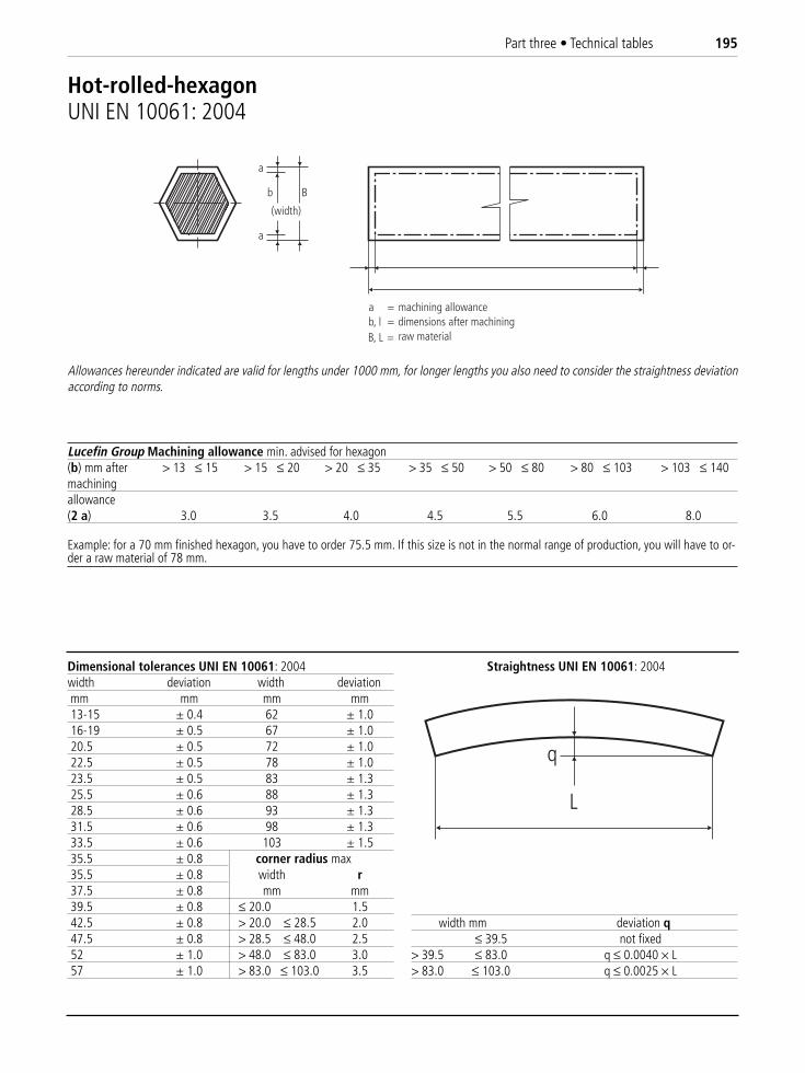
Part three • Technical tables 195
Dimensional tolerances UNI EN 10061: 2004width deviation width deviationmm mm mm mm13-15 ± 0.4 62 ± 1.016-19 ± 0.5 67 ± 1.020.5 ± 0.5 72 ± 1.022.5 ± 0.5 78 ± 1.023.5 ± 0.5 83 ± 1.325.5 ± 0.6 88 ± 1.328.5 ± 0.6 93 ± 1.331.5 ± 0.6 98 ± 1.333.5 ± 0.6 103 ± 1.535.5 ± 0.8 corner radius max35.5 ± 0.8 width r37.5 ± 0.8 mm mm39.5 ± 0.8 ≤ 20.0 1.542.5 ± 0.8 > 20.0 ≤ 28.5 2.047.5 ± 0.8 > 28.5 ≤ 48.0 2.552 ± 1.0 > 48.0 ≤ 83.0 3.057 ± 1.0 > 83.0 ≤ 103.0 3.5
Lucefin Group Machining allowance min. advised for hexagon(b) mm after > 13 ≤ 15 > 15 ≤ 20 > 20 ≤ 35 > 35 ≤ 50 > 50 ≤ 80 > 80 ≤ 103 > 103 ≤ 140machiningallowance(2 a) 3.0 3.5 4.0 4.5 5.5 6.0 8.0
Example: for a 70 mm finished hexagon, you have to order 75.5 mm. If this size is not in the normal range of production, you will have to or-der a raw material of 78 mm.
a
b B
a
(width)
a = machining allowanceb, l = dimensions after machining
raw materialB, L =
Allowances hereunder indicated are valid for lengths under 1000 mm, for longer lengths you also need to consider the straightness deviationaccording to norms.
Straightness UNI EN 10061: 2004
q
L
width mm deviation q≤ 39.5 not fixed
> 39.5 ≤ 83.0 q ≤ 0.0040 × L> 83.0 ≤ 103.0 q ≤ 0.0025 × L
Hot-rolled-hexagonUNI EN 10061: 2004
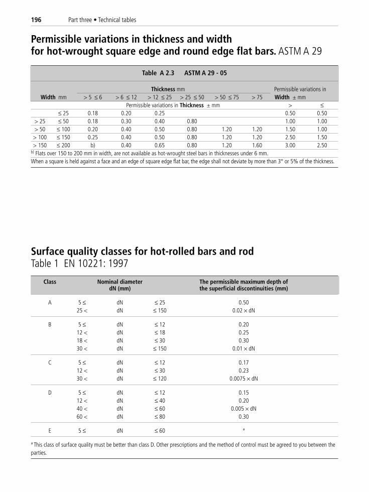
196 Part three • Technical tables
Table A 2.3 ASTM A 29 - 05
Thickness mm Permissible variations inWidth mm > 5 ≤ 6 > 6 ≤ 12 > 12 ≤ 25 > 25 ≤ 50 > 50 ≤ 75 > 75 Width ± mm
Permissible variations in Thickness ± mm > ≤≤ 25 0.18 0.20 0.25 0.50 0.50
> 25 ≤ 50 0.18 0.30 0.40 0.80 1.00 1.00> 50 ≤ 100 0.20 0.40 0.50 0.80 1.20 1.20 1.50 1.00> 100 ≤ 150 0.25 0.40 0.50 0.80 1.20 1.20 2.50 1.50> 150 ≤ 200 b) 0.40 0.65 0.80 1.20 1.60 3.00 2.50
b) Flats over 150 to 200 mm in width, are not available as hot-wrought steel bars in thicknesses under 6 mm.When a square is held against a face and an edge of square edge flat bar, the edge shall not deviate by more than 3° or 5% of the thickness.
Permissible variations in thickness and widthfor hot-wrought square edge and round edge flat bars. ASTM A 29
Class Nominal diameter The permissible maximum depth ofdN (mm) the superficial discontinuities (mm)
A 5 ≤ dN ≤ 25 0.5025 < dN ≤ 150 0.02 × dN
B 5 ≤ dN ≤ 12 0.2012 < dN ≤ 18 0.2518 < dN ≤ 30 0.3030 < dN ≤ 150 0.01 × dN
C 5 ≤ dN ≤ 12 0.1712 < dN ≤ 30 0.2330 < dN ≤ 120 0.0075 × dN
D 5 ≤ dN ≤ 12 0.1512 < dN ≤ 40 0.2040 < dN ≤ 60 0.005 × dN60 < dN ≤ 80 0.30
E 5 ≤ dN ≤ 60 ª
ª This class of surface quality must be better than class D. Other prescriptions and the method of control must be agreed to you between theparties.
Surface quality classes for hot-rolled bars and rodTable 1 EN 10221: 1997
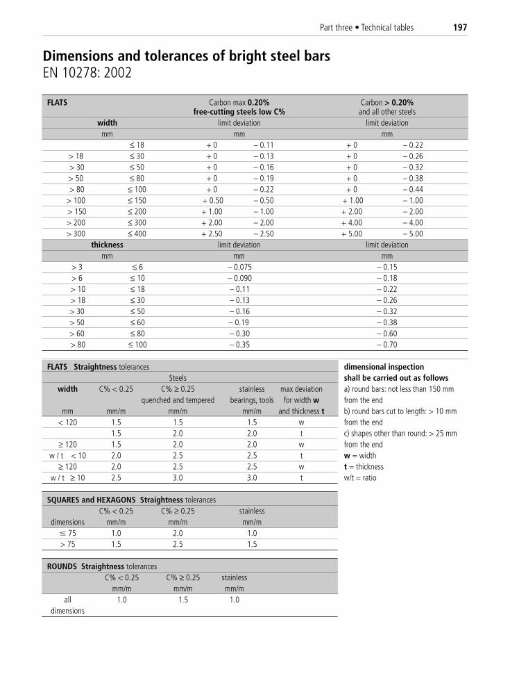
Part three • Technical tables 197
FLATS Carbon max 0.20% Carbon > 0.20%free-cutting steels low C% and all other steels
width limit deviation limit deviationmm mm mm
≤ 18 + 0 – 0.11 + 0 – 0.22> 18 ≤ 30 + 0 – 0.13 + 0 – 0.26> 30 ≤ 50 + 0 – 0.16 + 0 – 0.32> 50 ≤ 80 + 0 – 0.19 + 0 – 0.38> 80 ≤ 100 + 0 – 0.22 + 0 – 0.44
> 100 ≤ 150 + 0.50 – 0.50 + 1.00 – 1.00> 150 ≤ 200 + 1.00 – 1.00 + 2.00 – 2.00> 200 ≤ 300 + 2.00 – 2.00 + 4.00 – 4.00> 300 ≤ 400 + 2.50 – 2.50 + 5.00 – 5.00
thickness limit deviation limit deviationmm mm mm
> 3 ≤ 6 – 0.075 – 0.15> 6 ≤ 10 – 0.090 – 0.18> 10 ≤ 18 – 0.11 – 0.22> 18 ≤ 30 – 0.13 – 0.26> 30 ≤ 50 – 0.16 – 0.32> 50 ≤ 60 – 0.19 – 0.38> 60 ≤ 80 – 0.30 – 0.60> 80 ≤ 100 – 0.35 – 0.70
FLATS Straightness tolerances dimensional inspectionSteels shall be carried out as follows
width C% < 0.25 C% ≥ 0.25 stainless max deviation a) round bars: not less than 150 mmquenched and tempered bearings, tools for width w from the end
mm mm/m mm/m mm/m and thickness t b) round bars cut to length: > 10 mm< 120 1.5 1.5 1.5 w from the end
1.5 2.0 2.0 t c) shapes other than round: > 25 mm≥ 120 1.5 2.0 2.0 w from the end
w / t < 10 2.0 2.5 2.5 t w = width≥ 120 2.0 2.5 2.5 w t = thickness
w / t ≥ 10 2.5 3.0 3.0 t w/t = ratio
SQUARES and HEXAGONS Straightness tolerancesC% < 0.25 C% ≥ 0.25 stainless
dimensions mm/m mm/m mm/m� 75 1.0 2.0 1.0> 75 1.5 2.5 1.5
ROUNDS Straightness tolerancesC% < 0.25 C% ≥ 0.25 stainless
mm/m mm/m mm/mall 1.0 1.5 1.0
dimensions
Dimensions and tolerances of bright steel barsEN 10278: 2002
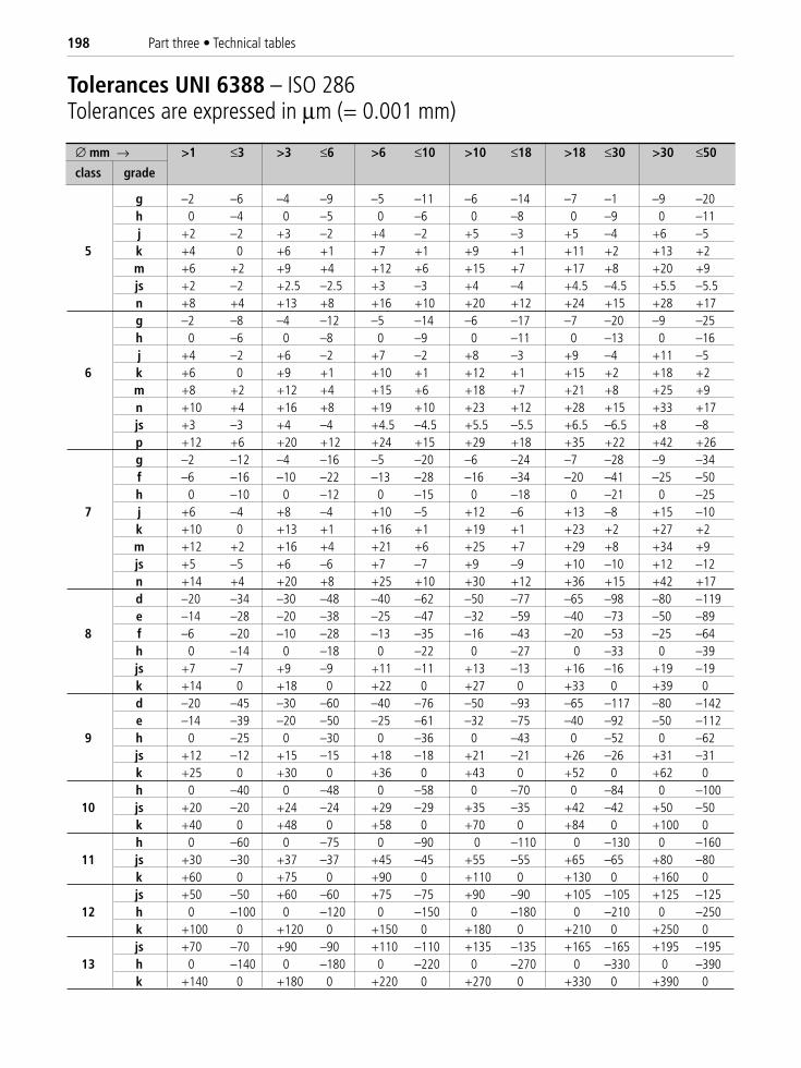
198 Part three • Technical tables
∅ mm → >1 ≤3 >3 ≤6 >6 ≤10 >10 ≤18 >18 ≤30 >30 ≤50
class grade
g –2 –6 –4 –9 –5 –11 –6 –14 –7 –1 –9 –20h 0 –4 0 –5 0 –6 0 –8 0 –9 0 –11j +2 –2 +3 –2 +4 –2 +5 –3 +5 –4 +6 –5
5 k +4 0 +6 +1 +7 +1 +9 +1 +11 +2 +13 +2m +6 +2 +9 +4 +12 +6 +15 +7 +17 +8 +20 +9js +2 –2 +2.5 –2.5 +3 –3 +4 –4 +4.5 –4.5 +5.5 –5.5n +8 +4 +13 +8 +16 +10 +20 +12 +24 +15 +28 +17g –2 –8 –4 –12 –5 –14 –6 –17 –7 –20 –9 –25h 0 –6 0 –8 0 –9 0 –11 0 –13 0 –16j +4 –2 +6 –2 +7 –2 +8 –3 +9 –4 +11 –5
6 k +6 0 +9 +1 +10 +1 +12 +1 +15 +2 +18 +2m +8 +2 +12 +4 +15 +6 +18 +7 +21 +8 +25 +9n +10 +4 +16 +8 +19 +10 +23 +12 +28 +15 +33 +17js +3 –3 +4 –4 +4.5 –4.5 +5.5 –5.5 +6.5 –6.5 +8 –8p +12 +6 +20 +12 +24 +15 +29 +18 +35 +22 +42 +26g –2 –12 –4 –16 –5 –20 –6 –24 –7 –28 –9 –34f –6 –16 –10 –22 –13 –28 –16 –34 –20 –41 –25 –50h 0 –10 0 –12 0 –15 0 –18 0 –21 0 –25
7 j +6 –4 +8 –4 +10 –5 +12 –6 +13 –8 +15 –10k +10 0 +13 +1 +16 +1 +19 +1 +23 +2 +27 +2m +12 +2 +16 +4 +21 +6 +25 +7 +29 +8 +34 +9js +5 –5 +6 –6 +7 –7 +9 –9 +10 –10 +12 –12n +14 +4 +20 +8 +25 +10 +30 +12 +36 +15 +42 +17d –20 –34 –30 –48 –40 –62 –50 –77 –65 –98 –80 –119e –14 –28 –20 –38 –25 –47 –32 –59 –40 –73 –50 –89
8 f –6 –20 –10 –28 –13 –35 –16 –43 –20 –53 –25 –64h 0 –14 0 –18 0 –22 0 –27 0 –33 0 –39js +7 –7 +9 –9 +11 –11 +13 –13 +16 –16 +19 –19k +14 0 +18 0 +22 0 +27 0 +33 0 +39 0d –20 –45 –30 –60 –40 –76 –50 –93 –65 –117 –80 –142e –14 –39 –20 –50 –25 –61 –32 –75 –40 –92 –50 –112
9 h 0 –25 0 –30 0 –36 0 –43 0 –52 0 –62js +12 –12 +15 –15 +18 –18 +21 –21 +26 –26 +31 –31k +25 0 +30 0 +36 0 +43 0 +52 0 +62 0h 0 –40 0 –48 0 –58 0 –70 0 –84 0 –100
10 js +20 –20 +24 –24 +29 –29 +35 –35 +42 –42 +50 –50k +40 0 +48 0 +58 0 +70 0 +84 0 +100 0h 0 –60 0 –75 0 –90 0 –110 0 –130 0 –160
11 js +30 –30 +37 –37 +45 –45 +55 –55 +65 –65 +80 –80k +60 0 +75 0 +90 0 +110 0 +130 0 +160 0js +50 –50 +60 –60 +75 –75 +90 –90 +105 –105 +125 –125
12 h 0 –100 0 –120 0 –150 0 –180 0 –210 0 –250k +100 0 +120 0 +150 0 +180 0 +210 0 +250 0js +70 –70 +90 –90 +110 –110 +135 –135 +165 –165 +195 –195
13 h 0 –140 0 –180 0 –220 0 –270 0 –330 0 –390k +140 0 +180 0 +220 0 +270 0 +330 0 +390 0
Tolerances UNI 6388 – ISO 286Tolerances are expressed in μm (= 0.001 mm)
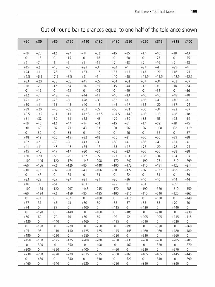
Part three • Technical tables 199
>50 ≤80 >80 ≤120 >120 ≤180 >180 ≤250 >250 ≤315 >315 ≤400
–10 –23 –12 –27 –14 –32 –15 –35 –17 –40 –18 –430 –13 0 –15 0 –18 0 –20 0 –23 0 –25
+6 –7 +6 –9 +7 –11 +7 –13 +7 –16 +7 –18+15 +2 +18 +3 +21 +3 +24 +4 +27 +4 +29 +4+24 +11 +28 +13 +33 +15 +37 +17 +43 +20 +46 +21+6.5 –6.5 +7.5 –7.5 +9 –9 +10 –10 +11.5 –11.5 +12.5 –12.5+33 +20 +38 +23 +45 +27 +51 +31 +57 +34 +62 +37–10 –29 –12 –34 –14 –39 –15 –44 –17 –49 –18 –54
0 –19 0 –22 0 –25 0 –29 0 –32 0 –36+12 –7 +13 –9 +14 –11 +16 –13 +16 –16 +18 –18+21 +2 +25 +3 +28 +3 +33 +4 +36 +4 +40 +4+30 +11 +35 +13 +40 +15 +46 +17 +52 +20 +57 +21+39 +20 +45 +23 +52 +27 +60 +31 +66 +34 +73 +37+9.5 –9.5 +11 –11 +12.5 –12.5 +14.5 –14.5 +16 –16 +18 –18+51 +32 +59 +37 +68 +43 +79 +50 +88 +56 +98 +62–10 –40 –12 –47 –14 –54 –15 –61 –17 –69 –18 –75–30 –60 –36 –71 –43 –83 –50 –96 –56 –108 –62 –119
0 –30 0 –35 0 –40 0 –46 0 –52 0 –57+18 –12 +20 –15 +22 –18 +25 –21 +26 –26 +29 –28+32 +2 +38 +3 +43 +3 +50 +4 +56 +4 +61 +4+41 +11 +48 +13 +55 +15 +63 +17 +72 +20 +78 +21+15 –15 +17 –17 +20 –20 +23 –23 +26 –26 +28 –28+50 +20 +58 +23 +67 +27 +77 +31 +86 +34 +94 +37–100 –146 –120 –174 –145 –208 –170 –242 –190 –271 –210 –299–60 –106 –72 –126 –85 –148 –100 –172 –110 –191 –125 –214–30 –76 –36 –90 –43 –106 –50 –122 –56 –137 –62 –151
0 –46 0 –54 0 –63 0 –72 0 –81 0 –89+23 –23 +27 –27 +31 –31 +36 –36 +40 –40 +44 –44+46 0 +54 0 +63 0 +72 0 +81 0 +89 0–100 –174 –120 –207 –145 –245 –170 –285 –190 –320 –210 –350–60 –134 –72 –159 –85 –185 –100 –215 –110 –240 –125 –265
0 –74 0 –87 0 –100 0 –115 0 –130 0 –140+37 –37 +43 –43 +50 –50 +57 –57 +65 –65 +70 –70+74 0 +87 0 +100 0 +115 0 +130 0 +140 0
0 –120 0 –140 0 –160 0 –185 0 –210 0 –230+60 –60 +70 –70 +80 –80 +92 –92 +105 –105 +115 –115+120 0 +140 0 +160 0 +185 0 +210 0 +230 0
0 –190 0 –220 0 –250 0 –290 0 –320 0 –360+95 –95 +110 –110 +125 –125 +145 –145 +160 –160 +180 –180+190 0 +220 0 +250 0 +290 0 +320 0 +360 0+150 –150 +175 –175 +200 –200 +230 –230 +260 –260 +285 –285
0 –300 0 –350 0 –400 0 –460 0 –520 0 –570+300 0 +350 0 +400 0 +460 0 +520 0 +570 0+230 –230 +270 –270 +315 –315 +360 –360 +405 –405 +445 –445
0 –460 0 –540 0 –630 0 –720 0 –810 0 –890+460 0 +540 0 +630 0 +720 0 +810 0 +890 0
Out-of-round bar tolerances equal to one half of the tolerance shown
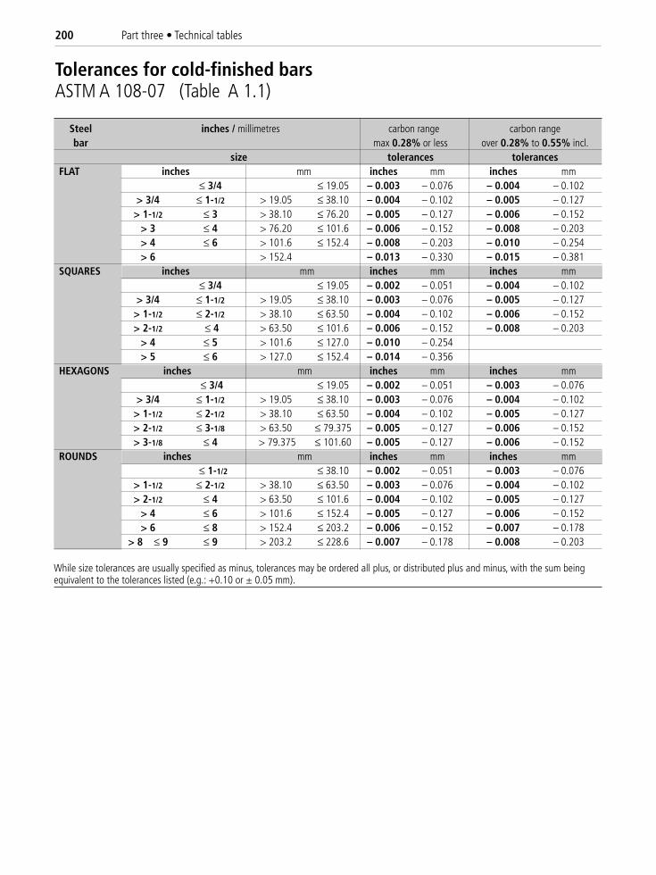
200 Part three • Technical tables
Tolerances for cold-finished barsASTM A 108-07 (Table A 1.1)
Steel inches / millimetres carbon range carbon range bar max 0.28% or less over 0.28% to 0.55% incl.
size tolerances tolerancesFLAT inches mm inches mm inches mm
≤ 3/4 ≤ 19.05 – 0.003 – 0.076 – 0.004 – 0.102> 3/4 ≤ 1-1/2 > 19.05 ≤ 38.10 – 0.004 – 0.102 – 0.005 – 0.127
> 1-1/2 ≤ 3 > 38.10 ≤ 76.20 – 0.005 – 0.127 – 0.006 – 0.152> 3 ≤ 4 > 76.20 ≤ 101.6 – 0.006 – 0.152 – 0.008 – 0.203> 4 ≤ 6 > 101.6 ≤ 152.4 – 0.008 – 0.203 – 0.010 – 0.254> 6 > 152.4 – 0.013 – 0.330 – 0.015 – 0.381
SQUARES inches mm inches mm inches mm≤ 3/4 ≤ 19.05 – 0.002 – 0.051 – 0.004 – 0.102
> 3/4 ≤ 1-1/2 > 19.05 ≤ 38.10 – 0.003 – 0.076 – 0.005 – 0.127> 1-1/2 ≤ 2-1/2 > 38.10 ≤ 63.50 – 0.004 – 0.102 – 0.006 – 0.152> 2-1/2 ≤ 4 > 63.50 ≤ 101.6 – 0.006 – 0.152 – 0.008 – 0.203
> 4 ≤ 5 > 101.6 ≤ 127.0 – 0.010 – 0.254> 5 ≤ 6 > 127.0 ≤ 152.4 – 0.014 – 0.356
HEXAGONS inches mm inches mm inches mm≤ 3/4 ≤ 19.05 – 0.002 – 0.051 – 0.003 – 0.076
> 3/4 ≤ 1-1/2 > 19.05 ≤ 38.10 – 0.003 – 0.076 – 0.004 – 0.102> 1-1/2 ≤ 2-1/2 > 38.10 ≤ 63.50 – 0.004 – 0.102 – 0.005 – 0.127> 2-1/2 ≤ 3-1/8 > 63.50 ≤ 79.375 – 0.005 – 0.127 – 0.006 – 0.152> 3-1/8 ≤ 4 > 79.375 ≤ 101.60 – 0.005 – 0.127 – 0.006 – 0.152
ROUNDS inches mm inches mm inches mm≤ 1-1/2 ≤ 38.10 – 0.002 – 0.051 – 0.003 – 0.076
> 1-1/2 ≤ 2-1/2 > 38.10 ≤ 63.50 – 0.003 – 0.076 – 0.004 – 0.102> 2-1/2 ≤ 4 > 63.50 ≤ 101.6 – 0.004 – 0.102 – 0.005 – 0.127
> 4 ≤ 6 > 101.6 ≤ 152.4 – 0.005 – 0.127 – 0.006 – 0.152> 6 ≤ 8 > 152.4 ≤ 203.2 – 0.006 – 0.152 – 0.007 – 0.178
> 8 ≤ 9 ≤ 9 > 203.2 ≤ 228.6 – 0.007 – 0.178 – 0.008 – 0.203
While size tolerances are usually specified as minus, tolerances may be ordered all plus, or distributed plus and minus, with the sum beingequivalent to the tolerances listed (e.g.: +0.10 or ± 0.05 mm).
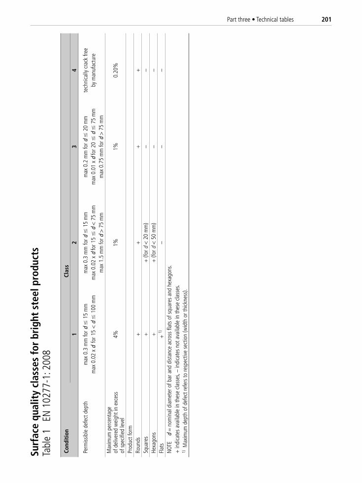
Part three • Technical tables 201
Surf
ace
qual
ity
clas
ses
for
brig
ht s
teel
pro
duct
sTa
ble
1 E
N 1
0277
-1: 2
008
Cond
itio
nCl
ass
12
34
Perm
issib
le d
efec
t dep
thm
ax 0
.3 m
m fo
rd �
15 m
m
max
0.3
mm
ford
�15
mm
max
0.2
mm
ford
�20
mm
te
chni
cally
cra
ck fr
eem
ax 0
.02
xd
for 1
5 <
d �
100
mm
max
0.0
2 x
d fo
r 15
�d
< 7
5 m
m
max
0.0
1 x
d fo
r 20
�d
� 7
5 m
mby
man
ufac
ture
max
1.5
mm
ford
> 7
5 m
mm
ax 0
.75
mm
ford
> 7
5 m
mM
axim
um p
erce
ntag
eof
del
iver
ed w
eigh
t in
exce
ss4%
1%1%
0.20
%of
spe
cifie
d le
vel
Prod
uct f
orm
Roun
ds+
++
+Sq
uare
s+
+ (f
or d
< 2
0 m
m)
––
Hexa
gons
+
+ (f
or d
< 5
0 m
m)
––
Flat
s+
1)–
––
NOT
E
d =
nom
inal
dia
met
er o
f bar
and
dist
ance
acr
oss
flats
of s
quar
es a
nd h
exag
ons.
+ in
dica
tes
avai
labl
e in
thes
e cla
sses
, –in
dica
tes
not a
vaila
ble
in th
ese
class
es.
1)M
axim
um d
epth
of d
efec
t ref
ers
to re
spec
tive
sect
ion
(wid
th o
r thi
ckne
ss).
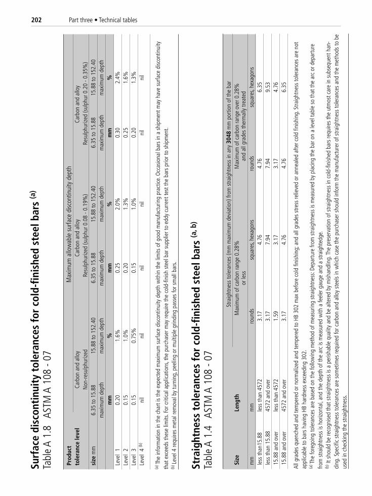
202 Part three • Technical tables
Prod
uct
Max
imum
allo
wab
le s
urfa
ce d
iscon
tinui
ty d
epth
tole
ranc
e le
vel
Carb
on a
nd a
lloy
Carb
on a
nd a
lloy
Carb
on a
nd a
lloy
Non
-resu
lphu
rized
Resu
lphu
rized
(sul
phur
0.0
8 - 0
.19%
)Re
sulp
huriz
ed (s
ulph
ur 0
.20
- 0.3
5%)
size
mm
6.35
to 1
5.88
15.8
8 to
152
.40
6.35
to 1
5.88
15
.88
to 1
52.4
06.
35 to
15.
88
15.8
8 to
152
.40
max
imum
dep
thm
axim
um d
epth
max
imum
dep
thm
axim
um d
epth
max
imum
dep
thm
axim
um d
epth
mm
%m
m%
mm
%Le
vel
10.
201.
6%0.
252.
0%0.
302.
4%Le
vel
20.
151.
0%0.
201.
3%0.
251.
6%Le
vel
30.
150.
75%
0.15
1.0%
0.20
1.3%
Leve
l 4
(b)
nil
nil
nil
nil
nil
nil
(a) T
he in
form
atio
n in
the
char
t is
the
expe
cted
max
imum
sur
face
disc
ontin
uity
dep
th w
ithin
the
limits
of g
ood
man
ufac
turin
g pr
actic
e. O
ccas
iona
l bar
s in
a s
hipm
ent m
ay h
ave
surfa
ce d
iscon
tinui
tyth
at e
xcee
ds th
ese
limits
. For
crit
ical a
pplic
atio
ns, t
he p
urch
aser
may
requ
ire th
e co
ld-fi
nish
ste
el b
ar s
uppl
ier t
o ed
dy c
urre
nt te
st th
e ba
rs p
rior t
o sh
ipm
ent.
(b) L
evel
4 re
quire
s m
etal
rem
oval
by
turn
ing,
pee
ling
or m
ultip
le g
rindi
ng p
asse
s fo
r sm
all b
ars.
Surf
ace
disc
onti
nuit
y to
lera
nces
for
cold
-fin
ishe
d st
eel b
ars
(a)
Tabl
e A
1.8
AST
M A
108
- 07
Stra
ight
ness
tole
ranc
es (m
m m
axim
um d
evia
tion)
from
stra
ight
ness
in a
ny 3
048
mm
por
tion
of th
e ba
rSi
ze
Leng
thM
axim
um o
f car
bon
rang
e 0.
28%
M
axim
um o
f car
bon
rang
e ov
er 0
.28%
or le
ssan
d al
l gra
des
ther
mal
ly tre
ated
mm
mm
roun
dssq
uare
s, he
xago
nsro
unds
squa
res,
hexa
gons
less
than
15.8
8le
ss th
an 4
572
3.17
4.76
4.76
6.35
less
than
15.
8845
72 a
nd o
ver
3.17
7.94
7.94
9.53
15.8
8 an
d ov
erle
ss th
an 4
572
1.59
3.17
3.17
4.76
15.8
8 an
d ov
er45
72 a
nd o
ver
3.17
4.76
4.76
6.35
All g
rade
s qu
ench
ed a
nd te
mpe
red
or n
orm
alize
d an
d te
mpe
red
to H
B 30
2 m
ax b
efor
e co
ld fi
nish
ing;
and
all
grad
es s
tress
relie
ved
or a
nnea
led
afte
r col
d fin
ishin
g. S
traig
htne
ss to
lera
nces
are
not
appl
icabl
e to
bar
s ha
ving
HB
hard
ness
exc
eedi
ng 3
02.
(a) T
he fo
rego
ing
tole
ranc
es a
re b
ased
on
the
follo
win
g m
etho
d of
mea
surin
g st
raig
htne
ss: D
epar
ture
from
stra
ight
ness
is m
easu
red
by p
lacin
g th
e ba
r on
a le
vel t
able
so
that
the
arc
or d
epar
ture
from
stra
ight
ness
is h
orizo
ntal
, and
the
dept
h of
the
arc
is m
easu
red
with
a fe
eler
gau
ge a
nd a
stra
ight
edge
.(b
)It
shou
ld b
e re
cogn
ised
that
stra
ight
ness
is a
per
ishab
le q
ualit
y an
d be
alte
red
by m
ishan
dlin
g. Th
e pr
eser
vatio
n of
stra
ight
ness
in c
old-
finish
ed b
ars
requ
ires
the
utm
ost c
are
in s
ubse
quen
t han
-di
ng. S
pecif
ic st
raig
htne
ss to
lera
nces
are
som
etim
es re
quire
d fo
r car
bon
and
allo
y st
eels
in w
hich
cas
e th
e pu
rcha
ser s
houl
d in
form
the
man
ufac
ture
r of s
traig
htne
ss to
lera
nces
and
the
met
hods
to b
eus
ed in
che
ckin
g th
e st
raig
htne
ss.
Stra
ight
ness
tol
eran
ces
for
cold
-fin
ishe
d st
eel b
ars
(a, b
)
Tabl
e A
1.4
AST
M A
108
- 07
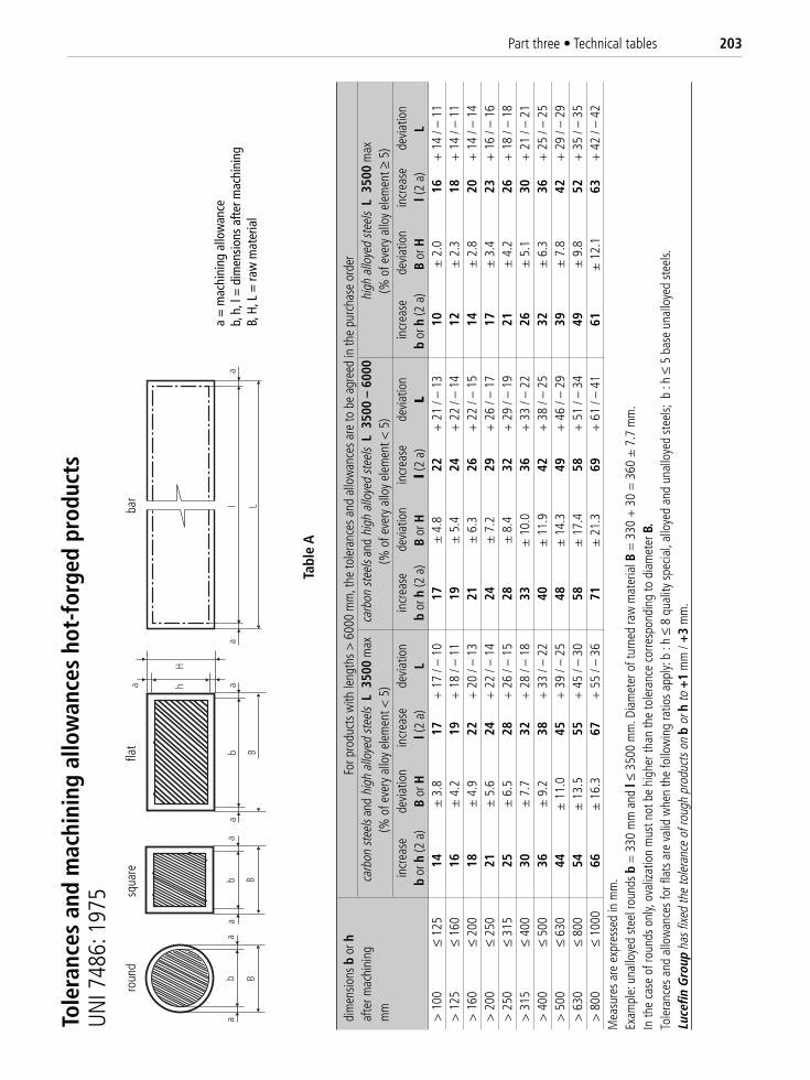
Part three • Technical tables 203
dim
ensio
ns b
or h
For p
rodu
cts
with
leng
ths
> 6
000
mm
, the
tole
ranc
es a
nd a
llow
ance
s ar
e to
be
agre
ed in
the
purc
hase
ord
eraf
ter m
achi
ning
carb
on st
eels
and
high
allo
yed
stee
ls L
350
0m
axca
rbon
stee
ls an
d hi
gh a
lloye
d st
eels
L 3
500
– 60
00hi
gh a
lloye
d st
eels
L 3
500
max
mm
(% o
f eve
ry a
lloy
elem
ent <
5)
(% o
f eve
ry a
lloy
elem
ent <
5)
(% o
f eve
ry a
lloy
elem
ent ≥
5)
incr
ease
devi
atio
nin
crea
sede
viat
ion
incr
ease
devi
atio
nin
crea
sede
viat
ion
incr
ease
devi
atio
nin
crea
sede
viat
ion
bor
h(2
a)
Bor
Hl(
2 a)
Lb
or h
(2 a
)B
or H
l (2
a)L
bor
h(2
a)
Bor
Hl(
2 a)
L>
100
≤ 12
514
± 3
.817
+ 1
7 / –
10
17±
4.8
22+
21
/ – 1
310
± 2
.016
+ 1
4 / –
11
> 1
25≤
160
16±
4.2
19+
18
/ – 1
119
± 5
.424
+ 2
2 / –
14
12±
2.3
18+
14
/ – 1
1>
160
≤ 20
018
± 4
.922
+ 2
0 / –
13
21±
6.3
26+
22
/ – 1
514
± 2
.820
+ 1
4 / –
14
> 2
00≤
250
21±
5.6
24+
22
/ – 1
424
± 7
.229
+ 2
6 / –
17
17±
3.4
23+
16
/ – 1
6>
250
≤ 31
525
± 6
.528
+ 2
6 / –
15
28±
8.4
32+
29
/ – 1
921
± 4
.226
+ 1
8 / –
18
> 3
15≤
400
30±
7.7
32+
28
/ – 1
833
± 1
0.0
36+
33
/ – 2
226
± 5
.130
+ 2
1 / –
21
> 4
00≤
500
36±
9.2
38+
33
/ – 2
240
± 1
1.9
42+
38
/ – 2
532
± 6
.336
+ 2
5 / –
25
> 5
00≤
630
44±
11.
045
+ 3
9 / –
25
48±
14.
349
+ 4
6 / –
29
39±
7.8
42+
29
/ – 2
9>
630
≤ 80
054
± 1
3.5
55+
45
/ – 3
058
± 1
7.4
58+
51
/ – 3
449
± 9
.852
+ 3
5 / –
35
> 8
00≤
1000
66±
16.
367
+ 5
5 / –
36
71±
21.
369
+ 6
1 / –
41
61±
12.
163
+ 4
2 / –
42
Mea
sure
s ar
e ex
pres
sed
in m
m.
Exam
ple:
una
lloye
d st
eel r
ound
s b
= 3
30 m
m a
nd l
≤ 35
00 m
m. D
iam
eter
of t
urne
d ra
w m
ater
ial B
= 3
30 +
30
= 3
60 ±
7.7
mm
.In
the
case
of r
ound
s on
ly, o
valiz
atio
n m
ust n
ot b
e hi
gher
than
the
tole
ranc
e co
rresp
ondi
ng to
dia
met
er B
.To
lera
nces
and
allo
wan
ces
for f
lats
are
val
id w
hen
the
follo
win
g ra
tios
appl
y: b
: h ≤
8 q
ualit
y sp
ecia
l, al
loye
d an
d un
allo
yed
stee
ls; b
: h
≤ 5
base
una
lloye
d st
eels.
Luce
fin G
roup
has f
ixed
the
tole
ranc
e of
roug
h pr
oduc
ts o
nb
orh
to+
1m
m /
+3
mm
.
Tole
ranc
es a
nd m
achi
ning
allo
wan
ces
hot-
forg
ed p
rodu
cts
UNI 7
486:
197
5
Tabl
e A
aa
l L
ab B
a
tond
o
aa
ba
a
B
b B
a hH
quad
ropi
atto
a =
mac
hini
ng a
llow
ance
b, h
, l =
dim
ensi
ons
afte
r mac
hini
ngB,
H, L
= ra
w m
ater
ial
roun
dsq
uare
flat
bar
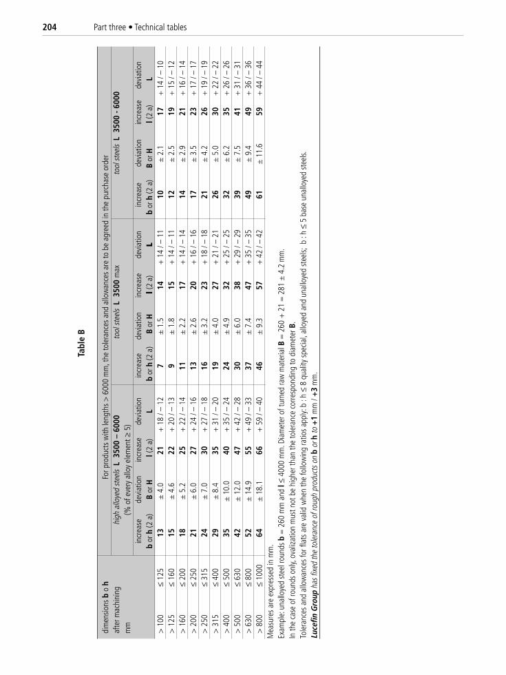
204 Part three • Technical tables
dim
ensio
ns b
o h
For p
rodu
cts
with
leng
ths
> 6
000
mm
, the
tole
ranc
es a
nd a
llow
ance
s ar
e to
be
agre
ed in
the
purc
hase
ord
eraf
ter m
achi
ning
high
allo
yed
stee
lsL
350
0 –
6000
tool
stee
lsL
350
0 m
axto
ol st
eels
L 3
500
- 600
0m
m(%
of e
very
allo
y el
emen
t ≥ 5
)in
crea
sede
viat
ion
incr
ease
devi
atio
nin
crea
sede
viat
ion
incr
ease
devi
atio
nin
crea
sede
viat
ion
incr
ease
devi
atio
nb
or h
(2 a
)B
or H
l(2
a)L
bor
h(2
a)
Bor
Hl (
2 a)
Lb
or h
(2 a
)B
or H
l(2
a)L
> 1
00≤
125
13±
4.0
21+
18
/ – 1
27
± 1
.514
+ 1
4 / –
11
10±
2.1
17+
14
/ – 1
0>
125
≤ 16
015
± 4
.622
+ 2
0 / –
13
9±
1.8
15+
14
/ – 1
112
± 2
.519
+ 1
5 / –
12
> 1
60≤
200
18±
5.2
25+
22
/ – 1
411
± 2
.217
+ 1
4 / –
14
14±
2.9
21+
16
/ – 1
4>
200
≤ 25
021
± 6
.027
+ 2
4 / –
16
13±
2.6
20+
16
/ – 1
617
± 3
.523
+ 1
7 / –
17
> 2
50≤
315
24±
7.0
30+
27
/ – 1
816
± 3
.223
+ 1
8 / –
18
21±
4.2
26+
19
/ – 1
9>
315
≤ 40
029
± 8
.435
+ 3
1 / –
20
19±
4.0
27+
21
/ – 2
126
± 5
.030
+ 2
2 / –
22
> 4
00≤
500
35±
10.
040
+ 3
5 / –
24
24±
4.9
32+
25
/ – 2
532
± 6
.235
+ 2
6 / –
26
> 5
00≤
630
42±
12.
047
+ 4
2 / –
28
30±
6.0
38+
29
/ – 2
939
± 7
.541
+ 3
1 / –
31
> 6
30≤
800
52±
14.
955
+ 4
9 / –
33
37±
7.4
47+
35
/ – 3
549
± 9
.449
+ 3
6 / –
36
> 8
00≤
1000
64±
18.
166
+ 5
9 / –
40
46±
9.3
57+
42
/ – 4
261
± 1
1.6
59+
44
/ – 4
4M
easu
res
are
expr
esse
d in
mm
.Ex
ampl
e: u
nallo
yed
stee
l rou
nds
b=
260
mm
and
l≤
4000
mm
. Dia
met
er o
f tur
ned
raw
mat
eria
l B=
260
+ 2
1 =
281
± 4
.2 m
m.
In th
e ca
se o
f rou
nds
only,
ova
lizat
ion
mus
t not
be
high
er th
an th
e to
lera
nce
corre
spon
ding
to d
iam
eter
B.
Tole
ranc
es a
nd a
llow
ance
s fo
r fla
ts a
re v
alid
whe
n th
e fo
llow
ing
ratio
s ap
ply:
b : h
≤ 8
qua
lity
spec
ial,
allo
yed
and
unal
loye
d st
eels;
b :
h ≤
5 ba
se u
nallo
yed
stee
ls.Lu
cefin
Gro
upha
s fixe
d th
e to
lera
nce
of ro
ugh
prod
ucts
on
bor
hto
+1
mm
/ +
3m
m.
Tabl
e B
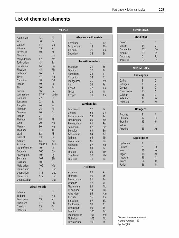
Part three • Technical tables 205
Aluminium 13 AlZinc 30 ZnGallium 31 GaYttrium 39 YZirconium 40 ZrNiobium 41 NbMolybdenum 42 MoTechnetium 43 TcRuthenium 44 RuRhodium 45 RhPalladium 46 PdSilver 47 AgCadmium 48 CdIndium 49 InTin 50 SnBarium 56 BaLanthanide 57-71 La-LuHafnium 72 HfTantalum 73 TaTungsten 74 WRhenium 75 ReOsmium 76 OsIridium 77 IrPlatinum 78 PlGold 79 AuMercury 80 HgThallium 81 TlLead 82 PbBismuth 83 BiRadium 88 RaActinide 89-103 Ac-LrRutherfordium 104 RfDubnium 105 DbSeaborgium 106 SgBohrium 107 BhHassium 108 HsMeitnerium 109 MtUnunnilium 110 UunUnununium 111 UuuUnunbium 112 UubUnunquadiun 114 Uuq
Alkali metals
Lithium 3 LiSodium 11 NaPotassium 19 KRubidium 37 RbCaesium 55 CsFrancium 87 Fr
Alkaline earth metals
Beryllium 4 BeMagnesium 12 MgCalcium 20 CaStrontium 38 Sr
Transition metals
Scandium 21 ScTitanium 22 TiVanadium 23 VChromium 24 CrManganese 25 MnIron 26 FeCobalt 27 CoNickel 28 NiCopper 29 Cu
Metalloids
Boron 5 BSilicon 14 SiGermanium 32 GeArsenic 33 AsAntimony 51 SbTellurium 52 Te
Chalcogens
Carbon 6 CNitrogen 7 NOxygen 8 OPhosphorus 15 PSulphur 16 SSelenium 34 SePolonium 84 Po
Halogens
Fluorine 9 FChlorine 17 ClBromine 35 BrIodine 53 IAstatine 85 At
Noble gases
Hydrogen 1 HHelium 2 HeNeon 10 NeArgon 18 ArKrypton 36 KrXenon 54 XeRadon 86 Rn
Lanthanides
Lanthanum 57 LaCerium 58 CePraseodymium 59 PrNeodymium 60 NdPromethium 61 PmSamarium 62 SmEuropium 63 EuGadolinium 64 GdTerbium 65 TbDysprosium 66 DyHolmium 67 HoErbium 68 ErThulium 69 TmYtterbium 70 YbLutetium 71 Lu
Actinides
Actinium 89 AcThorium 90 ThProtactinium 91 PaUranium 92 UNeptunium 93 NpPlutonium 94 PuAmericium 95 AmCurium 96 CmBerkelium 97 BkCalifornium 98 CfEinsteinium 99 EsFermium 100 FmMendelevium 101 MdNobelium 102 NoLawrencium 103 Lr
Element name (Aluminium) Atomic number (13)Symbol (Al)
METALS SEMIMETALS
NON METALS
List of chemical elements
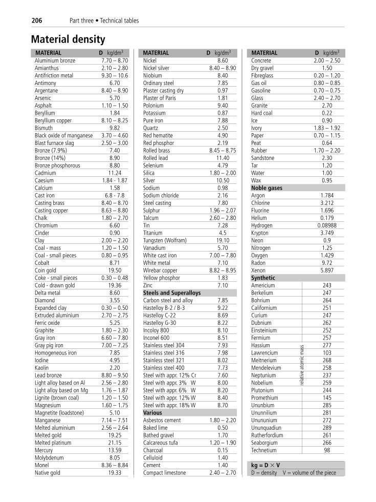
Aluminium bronze 7.70 – 8.70 Nickel 8.60 Concrete 2.00 – 2.50Amianthus 2.10 – 2.80 Nickel silver 8.40 – 8.90 Dry gravel 1.50Antifriction metal 9.30 – 10.6 Niobium 8.40 Fibreglass 0.20 – 1.20Antimony 6.70 Ordinary steel 7.85 Gas oil 0.80 – 0.85Argentane 8.40 – 8.90 Plaster casting dry 0.97 Gasoline 0.70 – 0.75Arsenic 5.70 Plaster of Paris 1.81 Glass 2.40 – 2.70Asphalt 1.10 – 1.50 Polonium 9.40 Granite 2.70Beryllium 1.84 Potassium 0.87 Hard coal 0.22Beryllium copper 8.10 – 8.25 Pure iron 7.88 Ice 0.90Bismuth 9.82 Quartz 2.50 Ivory 1.83 – 1.92Black oxide of manganese 3.70 – 4.60 Red hematite 4.90 Paper 0.70 – 1.15Blast furnace slag 2.50 – 3.00 Red phosphor 2.19 Peat 0.64Bronze (7.9%) 7.40 Rolled brass 8.45 – 8.75 Rubber 1.70 – 2.20Bronze (14%) 8.90 Rolled lead 11.40 Sandstone 2.30Bronze phosphorous 8.80 Selenium 4.79 Tar 1.20Cadmium 11.24 Silica 1.80 – 2.00 Water 1.00Caesium 1.84 - 1.87 Silver 10.50 Wax 0.95Calcium 1.58 Sodium 0.98 Noble gasesCast iron 6.8 - 7.8 Sodium chloride 2.16 Argon 1.784Casting brass 8.40 – 8.70 Steel casting 7.80 Chlorine 3.212Casting copper 8.63 – 8.80 Sulphur 1.96 – 2.07 Fluorine 1.696Chalk 1.80 – 2.70 Talcum 2.60 – 2.80 Helium 0.179Chromium 6.60 Tin 7.28 Hydrogen 0.08988Cinder 0.90 Titanium 4.5 Krypton 3.749Clay 2.00 – 2.20 Tungsten (Wolfram) 19.10 Neon 0.9Coal - mass 1.20 – 1.50 Vanadium 5.70 Nitrogen 1.25Coal - small pieces 0.80 – 0.95 White cast iron 7.00 – 7.80 Oxygen 1.429Cobalt 8.71 White metal 7.10 Radon 9.72Coin gold 19.50 Wirebar copper 8.82 – 8.95 Xenon 5.897Coke - small pieces 0.30 – 0.48 Yellow phosphor 1.83 SyntheticCold - drawn gold 19.36 Zinc 7.10 Americium 243Delta metal 8.60 Steels and Superalloys Berkelium 247Diamond 3.55 Carbon steel and alloy 7.85 Bohrium 264Expanded clay 0.30 – 0.50 Hastelloy B-2 / B-3 9.22 Californium 251Extruded aluminium 2.70 – 2.75 Hastelloy C-22 8.69 Curium 247Ferric oxide 5.25 Hastelloy G-30 8.22 Dubnium 262Graphite 1.80 – 2.30 Incoloy 800 8.10 Einsteinium 252Gray iron 6.60 – 7.80 Inconel 600 8.51 Fermium 257Gray pig iron 7.00 – 7.25 Stainless steel 304 7.93 Hassium 277Homogeneous iron 7.85 Stainless steel 316 7.98 Lawrencium 103Iodine 4.95 Stainless steel 321 8.02 Meitnerium 268Kaolin 2.20 Stainless steel 400 7.73 Mendelevium 258Lead bronze 8.80 – 9.50 Steel with appr. 12% Cr 7.60 Neptunium 237Light alloy based on Al 2.56 – 2.80 Steel with appr. 3% W 8.00 Nobelium 259Light alloy based on Mg 1.76 – 1.87 Steel with appr. 6% W 8.20 Plutonium 244Lignite (brown coal) 1.20 – 1.50 Steel with appr. 12% W 8.40 Promethium 145Magnesium 1.60 – 1.75 Steel with appr. 18% W 8.70 Ununbium 285Magnetite (loadstone) 5.10 Various Ununnilium 281Manganese 7.14 – 7.51 Asbestos cement 1.80 – 2.20 Unununium 272Melted aluminium 2.56 – 2.64 Baked lime 0.50 Ununquadiun 289Melted gold 19.25 Bathed gravel 1.70 Rutherfordium 261Melted platinum 21.15 Calcareous tufa 1.20 – 1.90 Seaborgium 266Mercury 13.59 Charcoal 0.15 Technetium 98Molybdenum 8.05 Celluloid 1.40Monel 8.36 – 8.84 Cement 1.40 kg = D � VNative gold 19.33 Compact limestone 2.40 – 2.70 D = density V = volume of the piece
206 Part three • Technical tables
MATERIAL D kg/dm3 MATERIAL D kg/dm3 MATERIAL D kg/dm3
Material density
rela
tive
atom
ic m
ass
Part three • Technical tables 207
Ac1 Temperature at which austenite starts to form, during heating.
Ac3 Temperature at which the transformation of ferrite into austenite stops, during heating.
Ms Temperature at which the transformation of austenite into martensite starts, during cooling.
Mf Temperature at which the transformation of austenite in martensite is complete, martensite finish.
Austenitisation Operation during which the material is heated to a temperature at which the structure becomesaustenitic.
Annealing The main requirement of this heat treatment is to achieve a lowering of the hardness of hot-deformed,rolled and cold-drawn materials.Annealing is introduced in some cases to eliminate stresses or non-homogeneous structures.
Bright annealing An annealing process that is carried out in a controlled atmosphere furnace (e.g. nitrogen) or inorder that oxidation is minimised and the surface remains relatively bright.
Brittleness This occurs in some hardened and tempered steels after a period of time held at a temperature of 450-525 °C, or during slow cooling within this range of temperatures. Causes loss of toughness.
Carbonitriding Heat and chemical treatment to obtain a higher carbon and nitrogen content on the surface. Boththese elements increase hardness.
Case-hardening Heat and chemical treatment to obtain a higher carbon content on the surface. Carbon increaseshardness and counteracts wear.
Case-hardening depth This is the distance between the surface and the layer at which the Vickers hardness, mea-sured under a load of 9.81 N, is HV1 = 550.
Chromium plating Electroplating treatment to form a film of extremely hard chromium on ground bars. This treat-ment provides abrasion and corrosion resistance, and a lower friction coefficient between moving parts; especially withrubber gaskets.
Chromizing Heat and chemical treatment to obtain a higher content of chromium on the surface.
Continuous patenting When the heating and cooling operations are carried out continuously.
Cooling Process for cooling a product by removing heat: nature and temperature of medium-environment, relativemovements, etc.
Cooling capacity Ability of a medium (air, oil, polymer, water, salt bath) to carry out a particular cooling programme.
Core quenching Hardening process carried out so that the depth of hardening is not less than the distance betweenthe core and the surface of the product.
Decarburizing A reduction of carbon in the surface layer of an iron product. The layer thickness may be defined withreference to a structural state or a level of hardness, or the carbon content in the unaltered base metal.
Deformation Alteration of the initial shape and dimensions of a product, during heat treatment.
Diffusion Operation to spread the elements previously introduced on the surface toward the core of the base metal.
Endothermic atmosphere Furnace atmosphere with an adjustable carbon potential.
Exothermic atmosphere Furnace atmosphere produced exothermically and controlled so that it does not oxidizethe material.
Notes on heat treatments
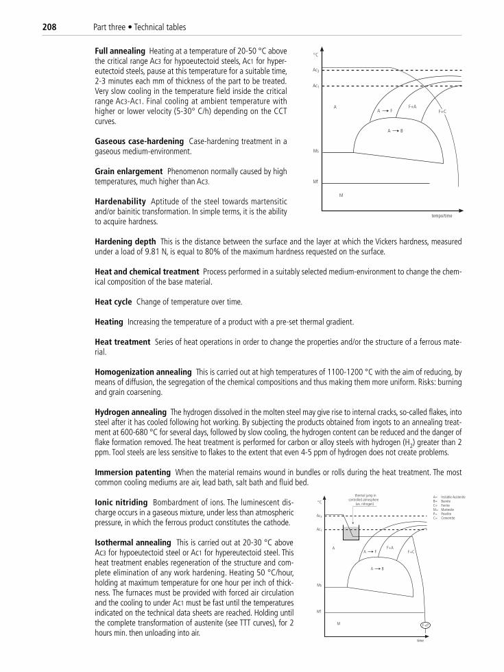
208 Part three • Technical tables
Full annealing Heating at a temperature of 20-50 °C abovethe critical range Ac3 for hypoeutectoid steels, Ac1 for hyper-eutectoid steels, pause at this temperature for a suitable time,2-3 minutes each mm of thickness of the part to be treated.Very slow cooling in the temperature field inside the criticalrange Ac3-Ac1. Final cooling at ambient temperature withhigher or lower velocity (5-30° C/h) depending on the CCTcurves.
Gaseous case-hardening Case-hardening treatment in agaseous medium-environment.
Grain enlargement Phenomenon normally caused by hightemperatures, much higher than Ac3.
Hardenability Aptitude of the steel towards martensiticand/or bainitic transformation. In simple terms, it is the abilityto acquire hardness.
Hardening depth This is the distance between the surface and the layer at which the Vickers hardness, measuredunder a load of 9.81 N, is equal to 80% of the maximum hardness requested on the surface.
Heat and chemical treatment Process performed in a suitably selected medium-environment to change the chem-ical composition of the base material.
Heat cycle Change of temperature over time.
Heating Increasing the temperature of a product with a pre-set thermal gradient.
Heat treatment Series of heat operations in order to change the properties and/or the structure of a ferrous mate-rial.
Homogenization annealing This is carried out at high temperatures of 1100-1200 °C with the aim of reducing, bymeans of diffusion, the segregation of the chemical compositions and thus making them more uniform. Risks: burningand grain coarsening.
Hydrogen annealing The hydrogen dissolved in the molten steel may give rise to internal cracks, so-called flakes, intosteel after it has cooled following hot working. By subjecting the products obtained from ingots to an annealing treat-ment at 600-680 °C for several days, followed by slow cooling, the hydrogen content can be reduced and the danger offlake formation removed. The heat treatment is performed for carbon or alloy steels with hydrogen (H2) greater than 2ppm. Tool steels are less sensitive to flakes to the extent that even 4-5 ppm of hydrogen does not create problems.
Immersion patenting When the material remains wound in bundles or rolls during the heat treatment. The mostcommon cooling mediums are air, lead bath, salt bath and fluid bed.
Ionic nitriding Bombardment of ions. The luminescent dis-charge occurs in a gaseous mixture, under less than atmosphericpressure, in which the ferrous product constitutes the cathode.
Isothermal annealing This is carried out at 20-30 °C aboveAc3 for hypoeutectoid steel or Ac1 for hypereutectoid steel. Thisheat treatment enables regeneration of the structure and com-plete elimination of any work hardening. Heating 50 °C/hour,holding at maximum temperature for one hour per inch of thick-ness. The furnaces must be provided with forced air circulationand the cooling to under Ac1 must be fast until the temperaturesindicated on the technical data sheets are reached. Holding untilthe complete transformation of austenite (see TTT curves), for 2hours min. then unloading into air.
thermal jump incontrolled atmosphere
(ex. nitrogen)
A F+AF+C
M
C
Ac3
Ac1
Ms
Mf
F+P
A F
A B
time
A= Instable AusteniteB= BainiteC= FerriteM= MartesiteP= PearliteC= Cementite
A F+AF+C
M
C
Ac3
Ac1
Ms
Mf
A F
A B
tempo/time
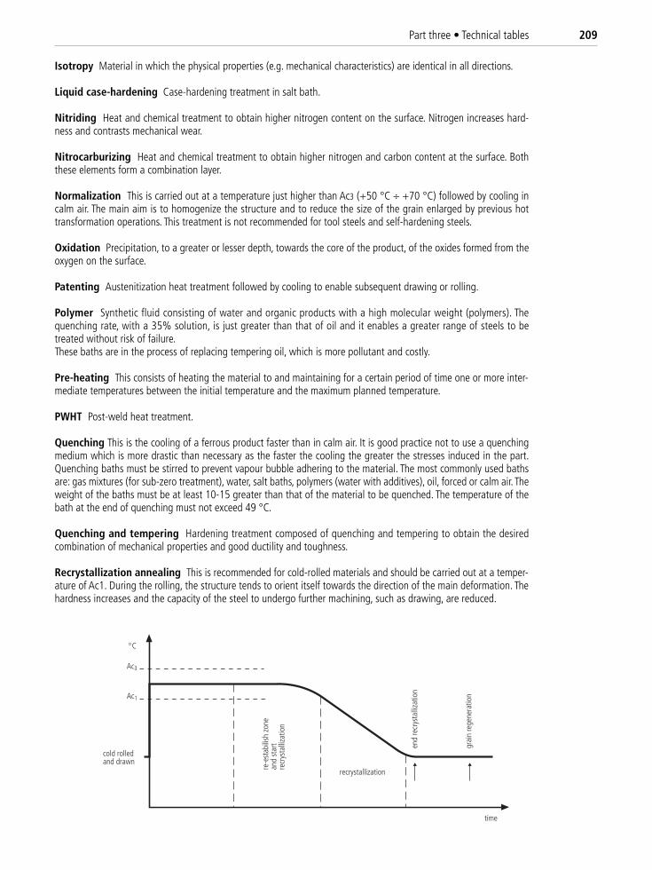
Part three • Technical tables 209
Isotropy Material in which the physical properties (e.g. mechanical characteristics) are identical in all directions.
Liquid case-hardening Case-hardening treatment in salt bath.
Nitriding Heat and chemical treatment to obtain higher nitrogen content on the surface. Nitrogen increases hard-ness and contrasts mechanical wear.
Nitrocarburizing Heat and chemical treatment to obtain higher nitrogen and carbon content at the surface. Boththese elements form a combination layer.
Normalization This is carried out at a temperature just higher than Ac3 (+50 °C ÷ +70 °C) followed by cooling incalm air. The main aim is to homogenize the structure and to reduce the size of the grain enlarged by previous hottransformation operations. This treatment is not recommended for tool steels and self-hardening steels.
Oxidation Precipitation, to a greater or lesser depth, towards the core of the product, of the oxides formed from theoxygen on the surface.
Patenting Austenitization heat treatment followed by cooling to enable subsequent drawing or rolling.
Polymer Synthetic fluid consisting of water and organic products with a high molecular weight (polymers). Thequenching rate, with a 35% solution, is just greater than that of oil and it enables a greater range of steels to betreated without risk of failure.These baths are in the process of replacing tempering oil, which is more pollutant and costly.
Pre-heating This consists of heating the material to and maintaining for a certain period of time one or more inter-mediate temperatures between the initial temperature and the maximum planned temperature.
PWHT Post-weld heat treatment.
Quenching This is the cooling of a ferrous product faster than in calm air. It is good practice not to use a quenchingmedium which is more drastic than necessary as the faster the cooling the greater the stresses induced in the part.Quenching baths must be stirred to prevent vapour bubble adhering to the material. The most commonly used bathsare: gas mixtures (for sub-zero treatment), water, salt baths, polymers (water with additives), oil, forced or calm air. Theweight of the baths must be at least 10-15 greater than that of the material to be quenched. The temperature of thebath at the end of quenching must not exceed 49 °C.
Quenching and tempering Hardening treatment composed of quenching and tempering to obtain the desiredcombination of mechanical properties and good ductility and toughness.
Recrystallization annealing This is recommended for cold-rolled materials and should be carried out at a temper-ature of Ac1. During the rolling, the structure tends to orient itself towards the direction of the main deformation. Thehardness increases and the capacity of the steel to undergo further machining, such as drawing, are reduced.
recrystallization
cold rolledand drawn
Ac3
Ac1
time
end
recr
ysta
lliza
tion
grai
n re
gene
ratio
n
re-e
stab
ilish
zon
ean
d st
art
recr
ysta
lliza
tion
C
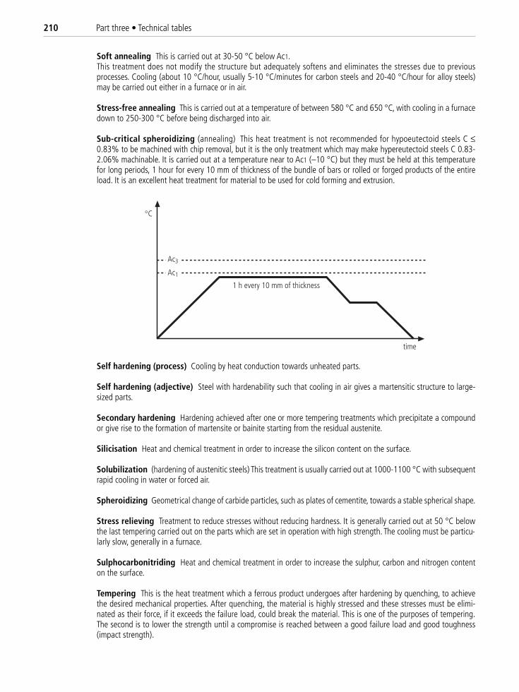
210 Part three • Technical tables
Soft annealing This is carried out at 30-50 °C below Ac1.This treatment does not modify the structure but adequately softens and eliminates the stresses due to previousprocesses. Cooling (about 10 °C/hour, usually 5-10 °C/minutes for carbon steels and 20-40 °C/hour for alloy steels)may be carried out either in a furnace or in air.
Stress-free annealing This is carried out at a temperature of between 580 °C and 650 °C, with cooling in a furnacedown to 250-300 °C before being discharged into air.
Sub-critical spheroidizing (annealing) This heat treatment is not recommended for hypoeutectoid steels C ≤0.83% to be machined with chip removal, but it is the only treatment which may make hypereutectoid steels C 0.83-2.06% machinable. It is carried out at a temperature near to Ac1 (–10 °C) but they must be held at this temperaturefor long periods, 1 hour for every 10 mm of thickness of the bundle of bars or rolled or forged products of the entireload. It is an excellent heat treatment for material to be used for cold forming and extrusion.
Self hardening (process) Cooling by heat conduction towards unheated parts.
Self hardening (adjective) Steel with hardenability such that cooling in air gives a martensitic structure to large-sized parts.
Secondary hardening Hardening achieved after one or more tempering treatments which precipitate a compoundor give rise to the formation of martensite or bainite starting from the residual austenite.
Silicisation Heat and chemical treatment in order to increase the silicon content on the surface.
Solubilization (hardening of austenitic steels) This treatment is usually carried out at 1000-1100 °C with subsequentrapid cooling in water or forced air.
Spheroidizing Geometrical change of carbide particles, such as plates of cementite, towards a stable spherical shape.
Stress relieving Treatment to reduce stresses without reducing hardness. It is generally carried out at 50 °C belowthe last tempering carried out on the parts which are set in operation with high strength. The cooling must be particu-larly slow, generally in a furnace.
Sulphocarbonitriding Heat and chemical treatment in order to increase the sulphur, carbon and nitrogen contenton the surface.
Tempering This is the heat treatment which a ferrous product undergoes after hardening by quenching, to achievethe desired mechanical properties. After quenching, the material is highly stressed and these stresses must be elimi-nated as their force, if it exceeds the failure load, could break the material. This is one of the purposes of tempering.The second is to lower the strength until a compromise is reached between a good failure load and good toughness(impact strength).
1 h every 10 mm of thickness
C
time
Ac3
Ac1
Part three • Technical tables 211
Useful experience:Considering 0 to be the strength after 2 hours of tempering, the variations in N/mm2 obtained by increasing and re-ducing the times maintained at the temperature are shown below.
Duration of tempering h 30’ 1 2 3 4 5 7 10Variation in strength N/mm2 +60 +30 0 –30 – 45 –50 – 60 – 80
Tempering diagram Graphic representation of the tempering treatment, including heating velocity and permanencetime at the established temperature. Diagram showing the relationship between the mechanical characteristics and thetempering temperature for a specific period of time at that temperature.
Thermal conductivity K K is the thermal conductivity coefficient, typical of a material, indicating the heat trans-mission ability (in the presence of a thermal gradient between the material faces and without convection or radiation).
[W]K = ––––––––––––––
[m] × [kelvin]
Time at temperature Time from when the part has reached the pre-set temperature at the core to the next changein temperature.A period of ½ hour per inch of thickness is normally used during quenching and 1 hour during tempering. These para-meters apply to forged parts in general and thicknesses greater than 50 mm.
Other method for wire rods, bundles and compact coils:
Temperature K Temperature K Temperature K Temperature K Temperature K575 °C 21 650 °C 31 750 °C 43 825 °C 51 900 °C 60600 °C 25 675 °C 34 775 °C 46 850 °C 54 925 °C 63625 °C 28 700 °C 37 800 °C 49 875 °C 57 950 °C 66
Maximum thickness mm/K = hours of active time at temperature Example: to normalize a Ø 400 mm at 900 °C (K = 60) 400/60 = 6.6 h– for wire rods the times reported above are suitable, and the dimension to be considered is the diameter of circum-scribed bundle– for compact coils, maximum time increased by 50% – for bundles of compact bars, times increased by 30%
Transformation diagrams Series of time/temperature diagrams which define the initial and final moments of thetransformation of austenite under isothermal conditions for each temperature level.
Wear-resistant coating Deposition of thin layers of very hard compounds which resist wear and corrosion, such as:
CVD Chemical Vapour DepositionDLC Diamond Like Carbon.HIP Hot Isostatic Pressing (application of heat and pressure to a metal)PCD Poli Crystalline Diamond (graphite, under pressure and at high temperature, mixed with Co or Ni).PVD Physical Vapour Deposition
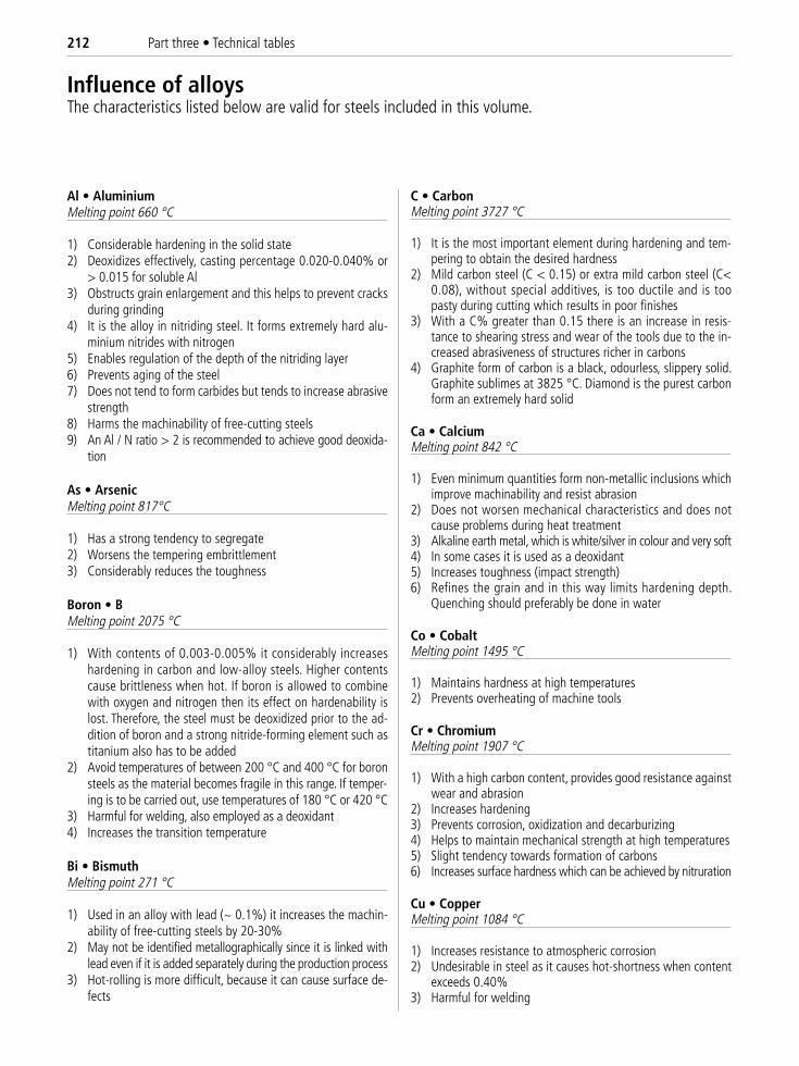
212 Part three • Technical tables
Al • AluminiumMelting point 660 °C
1) Considerable hardening in the solid state2) Deoxidizes effectively, casting percentage 0.020-0.040% or
> 0.015 for soluble Al 3) Obstructs grain enlargement and this helps to prevent cracks
during grinding 4) It is the alloy in nitriding steel. It forms extremely hard alu-
minium nitrides with nitrogen 5) Enables regulation of the depth of the nitriding layer6) Prevents aging of the steel7) Does not tend to form carbides but tends to increase abrasive
strength8) Harms the machinability of free-cutting steels9) An Al / N ratio > 2 is recommended to achieve good deoxida-
tion
As • ArsenicMelting point 817°C
1) Has a strong tendency to segregate2) Worsens the tempering embrittlement3) Considerably reduces the toughness
Boron • BMelting point 2075 °C
1) With contents of 0.003-0.005% it considerably increaseshardening in carbon and low-alloy steels. Higher contentscause brittleness when hot. If boron is allowed to combinewith oxygen and nitrogen then its effect on hardenability islost. Therefore, the steel must be deoxidized prior to the ad-dition of boron and a strong nitride-forming element such astitanium also has to be added
2) Avoid temperatures of between 200 °C and 400 °C for boronsteels as the material becomes fragile in this range. If temper-ing is to be carried out, use temperatures of 180 °C or 420 °C
3) Harmful for welding, also employed as a deoxidant4) Increases the transition temperature
Bi • Bismuth Melting point 271 °C
1) Used in an alloy with lead (~ 0.1%) it increases the machin-ability of free-cutting steels by 20-30%
2) May not be identified metallographically since it is linked withlead even if it is added separately during the production process
3) Hot-rolling is more difficult, because it can cause surface de-fects
C • CarbonMelting point 3727 °C
1) It is the most important element during hardening and tem-pering to obtain the desired hardness
2) Mild carbon steel (C < 0.15) or extra mild carbon steel (C<0.08), without special additives, is too ductile and is toopasty during cutting which results in poor finishes
3) With a C% greater than 0.15 there is an increase in resis-tance to shearing stress and wear of the tools due to the in-creased abrasiveness of structures richer in carbons
4) Graphite form of carbon is a black, odourless, slippery solid.Graphite sublimes at 3825 °C. Diamond is the purest carbonform an extremely hard solid
Ca • CalciumMelting point 842 °C
1) Even minimum quantities form non-metallic inclusions whichimprove machinability and resist abrasion
2) Does not worsen mechanical characteristics and does notcause problems during heat treatment
3) Alkaline earth metal, which is white/silver in colour and very soft4) In some cases it is used as a deoxidant5) Increases toughness (impact strength)6) Refines the grain and in this way limits hardening depth.
Quenching should preferably be done in water
Co • CobaltMelting point 1495 °C
1) Maintains hardness at high temperatures 2) Prevents overheating of machine tools
Cr • ChromiumMelting point 1907 °C
1) With a high carbon content, provides good resistance againstwear and abrasion
2) Increases hardening3) Prevents corrosion, oxidization and decarburizing4) Helps to maintain mechanical strength at high temperatures5) Slight tendency towards formation of carbons6) Increases surface hardness which can be achieved by nitruration
Cu • CopperMelting point 1084 °C
1) Increases resistance to atmospheric corrosion2) Undesirable in steel as it causes hot-shortness when content
exceeds 0.40% 3) Harmful for welding
Influence of alloysThe characteristics listed below are valid for steels included in this volume.
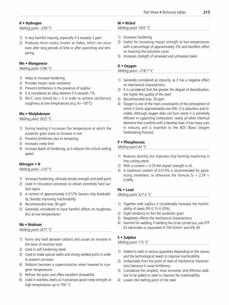
H • HydrogenMelting point –259 °C
1) A very harmful impurity, especially if it exceeds 2 ppm2) Produces micro-cracks, known as flakes, which can occur
even after long periods of time or after quenching and tem-pering
Mn • ManganeseMelting point 1246 °C
1) Helps to increase hardening2) Provides impact wear resistance3) Prevents brittleness in the presence of sulphur4) It is considered an alloy element if it exceeds 1%5) Mn/C ratio should be > 3 in order to achieve satisfactory
toughness at low temperatures (e.g. Kv –50°C)
Mo • MolybdenumMelting point 2623 °C
1) During heating it increases the temperature at which theaustenitic grain starts to increase in size
2) Prevents brittleness due to tempering3) Increases creep limit4) Increase depth of hardening, as it reduces the critical cooling
speed
Nitrogen • NMelting point –210 °C
1) Increases hardening, ultimate tensile strength and yield point2) Used in nitruration processes to obtain extremely hard sur-
face layers 3) A content of approximately 0.012% favours chip breakabil-
ity, thereby improving machinability4) Recommended max. 90 ppm 5) Generally considered to have harmful effects on toughness
(Kv) at low temperatures
Nb • NiobiumMelting point 2477 °C
1) Forms very hard abrasive carbons and causes an increase inthe wear of machine tools
2) Used in self-hardening steels3) Used to make special steels and strong welded joints in order
to prevent corrosion4) Niobium becomes a superconductor when lowered to cryo-
genic temperatures5) Refines the grain and offers excellent drawability6) Used in stainless steels as it possesses good creep strength at
high temperatures up to 700 °C
Ni • NickelMelting point 1455 °C
1) Increases hardening2) Useful for increasing impact strength at low temperatures
with a percentage of approximately 2% and excellent affecton lowering the transition curve
3) Increases strength of annealed and untreated steels
O • OxygenMelting point –218.7 °C
1) Generally considered an impurity, as it has a negative effecton mechanical characteristics
2) It is considered that the greater the degree of deoxidisation,the higher the quality of the steel
3) Recommended max. 30 ppm 4) Oxygen is one of the main constituents of the atmosphere of
which it forms approximately one fifth. It is odourless and in-visible. Although oxygen does not burn alone it is extremelyefficient in supporting combustion; nearly all other chemicalelements that combine with it develop heat. It has many usesin industry and is essential to the BOS (Basic OxygenSteelmaking Process)
P • PhosphorousMelting point 44 °C
1) Reduces ductility but improves chip-forming machining infree-cutting steels
2) With a content > 0.20 the impact strength is nil.3) A maximum content of 0.015% is recommended for galva-
nizing treatment, or otherwise the formula Si + 2.5P <0.09%
Pb • LeadMelting point 327.4 °C
1) Together with sulphur, it considerably increases the machin-ability of steels (Pb 0.15-0.35%)
2) Slight tendency to thin the austenitic grain 3) Negatively effects the mechanical characteristics 4) Harmful for welding. If welding has to be carried out, use UTP
63 electrodes or equivalent R 700 N/mm2 and A% 40
S • SulphurMelting point 115 °C
1) Added to steel in various quantities depending on the classesand the technological needs to improve machinability
2) Undesirable from the point of view of mechanical character-istics because it cause brittleness
3) Considered the simplest, most economic and effective addi-tive to be added to steel to improve the machinability
4) Lowers the melting point of the steel
Part three • Technical tables 213
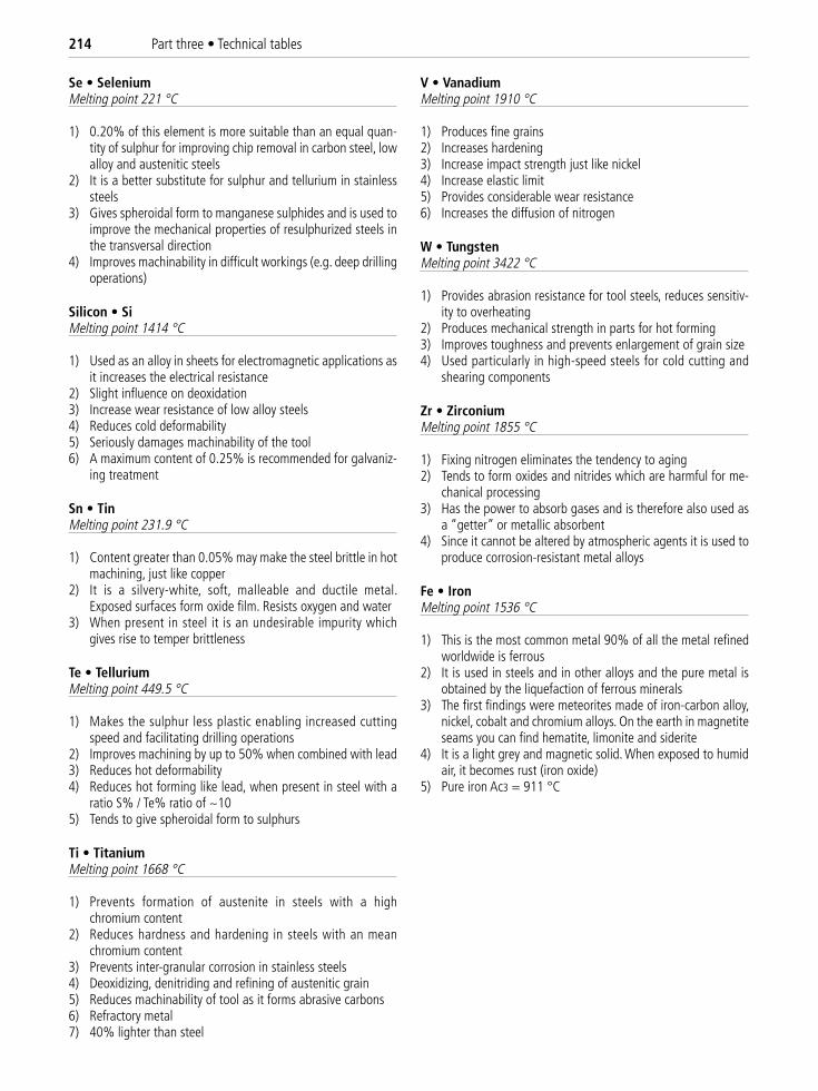
Se • SeleniumMelting point 221 °C
1) 0.20% of this element is more suitable than an equal quan-tity of sulphur for improving chip removal in carbon steel, lowalloy and austenitic steels
2) It is a better substitute for sulphur and tellurium in stainlesssteels
3) Gives spheroidal form to manganese sulphides and is used toimprove the mechanical properties of resulphurized steels inthe transversal direction
4) Improves machinability in difficult workings (e.g. deep drillingoperations)
Silicon • SiMelting point 1414 °C
1) Used as an alloy in sheets for electromagnetic applications asit increases the electrical resistance
2) Slight influence on deoxidation3) Increase wear resistance of low alloy steels4) Reduces cold deformability 5) Seriously damages machinability of the tool6) A maximum content of 0.25% is recommended for galvaniz-
ing treatment
Sn • TinMelting point 231.9 °C
1) Content greater than 0.05% may make the steel brittle in hotmachining, just like copper
2) It is a silvery-white, soft, malleable and ductile metal.Exposed surfaces form oxide film. Resists oxygen and water
3) When present in steel it is an undesirable impurity whichgives rise to temper brittleness
Te • Tellurium Melting point 449.5 °C
1) Makes the sulphur less plastic enabling increased cuttingspeed and facilitating drilling operations
2) Improves machining by up to 50% when combined with lead3) Reduces hot deformability4) Reduces hot forming like lead, when present in steel with a
ratio S% / Te% ratio of ~105) Tends to give spheroidal form to sulphurs
Ti • TitaniumMelting point 1668 °C
1) Prevents formation of austenite in steels with a highchromium content
2) Reduces hardness and hardening in steels with an meanchromium content
3) Prevents inter-granular corrosion in stainless steels 4) Deoxidizing, denitriding and refining of austenitic grain5) Reduces machinability of tool as it forms abrasive carbons6) Refractory metal7) 40% lighter than steel
V • VanadiumMelting point 1910 °C
1) Produces fine grains2) Increases hardening3) Increase impact strength just like nickel4) Increase elastic limit5) Provides considerable wear resistance6) Increases the diffusion of nitrogen
W • TungstenMelting point 3422 °C
1) Provides abrasion resistance for tool steels, reduces sensitiv-ity to overheating
2) Produces mechanical strength in parts for hot forming3) Improves toughness and prevents enlargement of grain size4) Used particularly in high-speed steels for cold cutting and
shearing components
Zr • ZirconiumMelting point 1855 °C
1) Fixing nitrogen eliminates the tendency to aging2) Tends to form oxides and nitrides which are harmful for me-
chanical processing3) Has the power to absorb gases and is therefore also used as
a “getter” or metallic absorbent4) Since it cannot be altered by atmospheric agents it is used to
produce corrosion-resistant metal alloys
Fe • IronMelting point 1536 °C
1) This is the most common metal 90% of all the metal refinedworldwide is ferrous
2) It is used in steels and in other alloys and the pure metal isobtained by the liquefaction of ferrous minerals
3) The first findings were meteorites made of iron-carbon alloy,nickel, cobalt and chromium alloys. On the earth in magnetiteseams you can find hematite, limonite and siderite
4) It is a light grey and magnetic solid. When exposed to humidair, it becomes rust (iron oxide)
5) Pure iron Ac3 = 911 °C
214 Part three • Technical tables
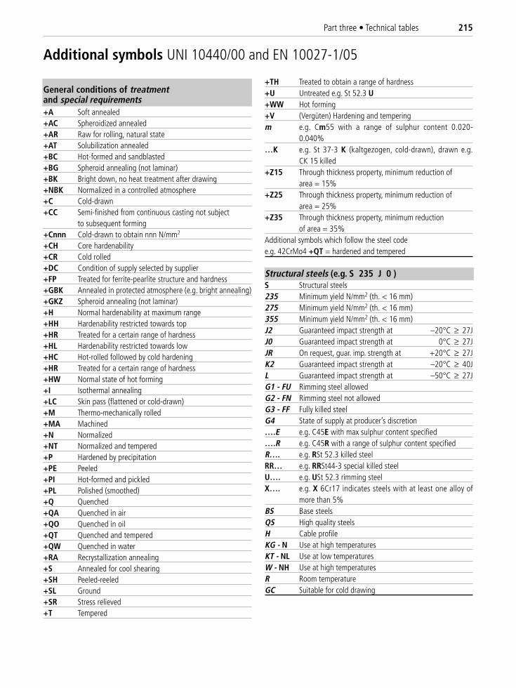
Part three • Technical tables 215
General conditions of treatmentand special requirements+A Soft annealed+AC Spheroidized annealed+AR Raw for rolling, natural state+AT Solubilization annealed+BC Hot-formed and sandblasted+BG Spheroid annealing (not laminar)+BK Bright down, no heat treatment after drawing+NBK Normalized in a controlled atmosphere+C Cold-drawn+CC Semi-finished from continuous casting not subject
to subsequent forming+Cnnn Cold-drawn to obtain nnn N/mm2
+CH Core hardenability+CR Cold rolled+DC Condition of supply selected by supplier+FP Treated for ferrite-pearlite structure and hardness+GBK Annealed in protected atmosphere (e.g. bright annealing)+GKZ Spheroid annealing (not laminar)+H Normal hardenability at maximum range+HH Hardenability restricted towards top+HR Treated for a certain range of hardness+HL Hardenability restricted towards low+HC Hot-rolled followed by cold hardening+HR Treated for a certain range of hardness+HW Normal state of hot forming+I Isothermal annealing+LC Skin pass (flattened or cold-drawn)+M Thermo-mechanically rolled+MA Machined+N Normalized+NT Normalized and tempered+P Hardened by precipitation+PE Peeled+PI Hot-formed and pickled+PL Polished (smoothed)+Q Quenched+QA Quenched in air+QO Quenched in oil+QT Quenched and tempered+QW Quenched in water+RA Recrystallization annealing+S Annealed for cool shearing+SH Peeled-reeled+SL Ground+SR Stress relieved+T Tempered
+TH Treated to obtain a range of hardness+U Untreated e.g. St 52.3 U+WW Hot forming+V (Vergüten) Hardening and temperingm e.g. Cm55 with a range of sulphur content 0.020-
0.040%…K e.g. St 37-3 K (kaltgezogen, cold-drawn), drawn e.g.
CK 15 killed+Z15 Through thickness property, minimum reduction of
area = 15%+Z25 Through thickness property, minimum reduction of
area = 25%+Z35 Through thickness property, minimum reduction
of area = 35%Additional symbols which follow the steel codee.g. 42CrMo4 +QT = hardened and tempered
Structural steels (e.g. S 235 J 0 )S Structural steels235 Minimum yield N/mm2 (th. < 16 mm)275 Minimum yield N/mm2 (th. < 16 mm)355 Minimum yield N/mm2 (th. < 16 mm)J2 Guaranteed impact strength at –20°C ≥ 27JJ0 Guaranteed impact strength at 0°C ≥ 27JJR On request, guar. imp. strength at +20°C ≥ 27JK2 Guaranteed impact strength at –20°C ≥ 40JL Guaranteed impact strength at –50°C ≥ 27JG1 - FU Rimming steel allowedG2 - FN Rimming steel not allowedG3 - FF Fully killed steelG4 State of supply at producer’s discretion….E e.g. C45E with max sulphur content specified….R e.g. C45R with a range of sulphur content specifiedR…. e.g. RSt 52.3 killed steelRR… e.g. RRSt44-3 special killed steelU…. e.g. USt 52.3 rimming steelX…. e.g. X 6Cr17 indicates steels with at least one alloy of
more than 5%BS Base steelsQS High quality steelsH Cable profileKG - N Use at high temperaturesKT - NL Use at low temperaturesW - NH Use at high temperaturesR Room temperatureGC Suitable for cold drawing
Additional symbols UNI 10440/00 and EN 10027-1/05
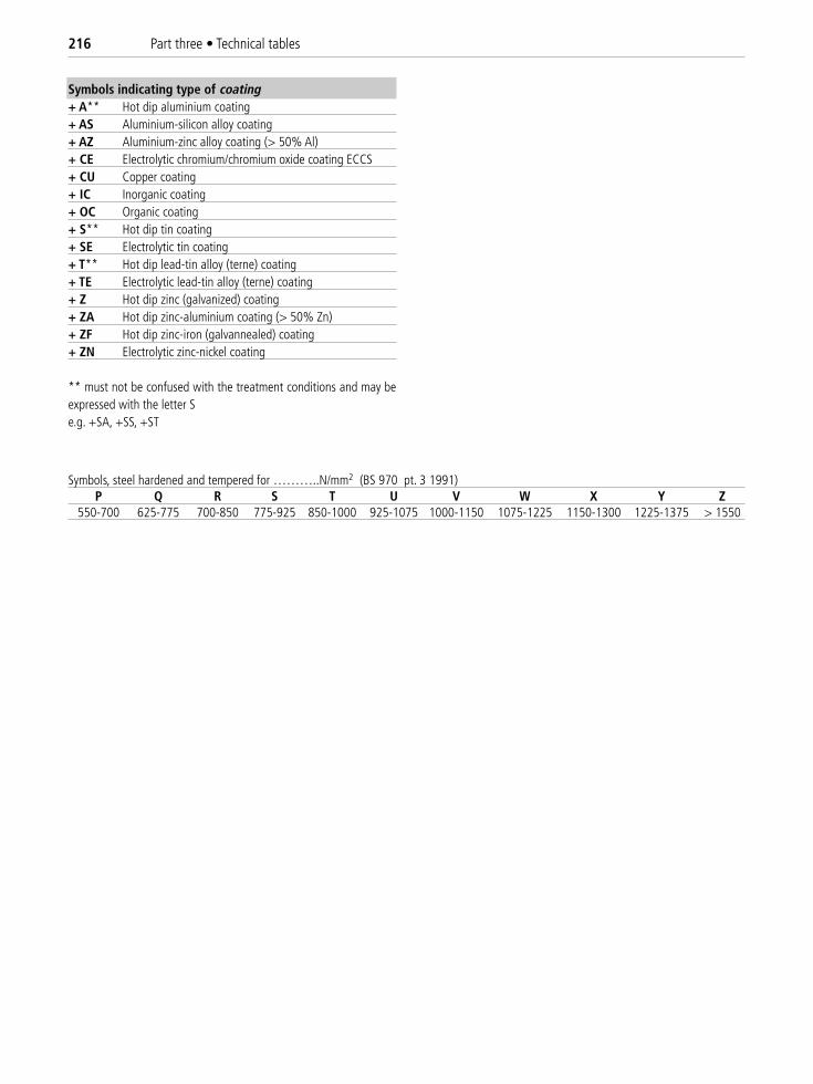
216 Part three • Technical tables
Symbols indicating type of coating+ A** Hot dip aluminium coating+ AS Aluminium-silicon alloy coating+ AZ Aluminium-zinc alloy coating (> 50% Al)+ CE Electrolytic chromium/chromium oxide coating ECCS+ CU Copper coating+ IC Inorganic coating+ OC Organic coating+ S** Hot dip tin coating+ SE Electrolytic tin coating+ T** Hot dip lead-tin alloy (terne) coating+ TE Electrolytic lead-tin alloy (terne) coating+ Z Hot dip zinc (galvanized) coating+ ZA Hot dip zinc-aluminium coating (> 50% Zn)+ ZF Hot dip zinc-iron (galvannealed) coating+ ZN Electrolytic zinc-nickel coating
** must not be confused with the treatment conditions and may beexpressed with the letter Se.g. +SA, +SS, +ST
Symbols, steel hardened and tempered for ………..N/mm2 (BS 970 pt. 3 1991)P Q R S T U V W X Y Z
550-700 625-775 700-850 775-925 850-1000 925-1075 1000-1150 1075-1225 1150-1300 1225-1375 > 1550
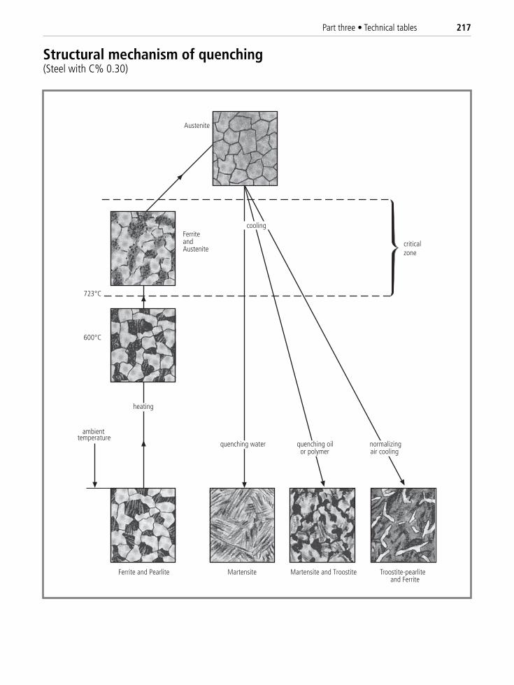
Part three • Technical tables 217
Austenite
FerriteandAustenite
criticalzone
723 C
600 C
heating
Martensite Martensite and Troostite Ferrite and Pearlite
temperatureambient
Troostite-pearlite and Ferrite
quenching water quenching oilor polymer
normalizingair cooling
cooling
Structural mechanism of quenching(Steel with C% 0.30)
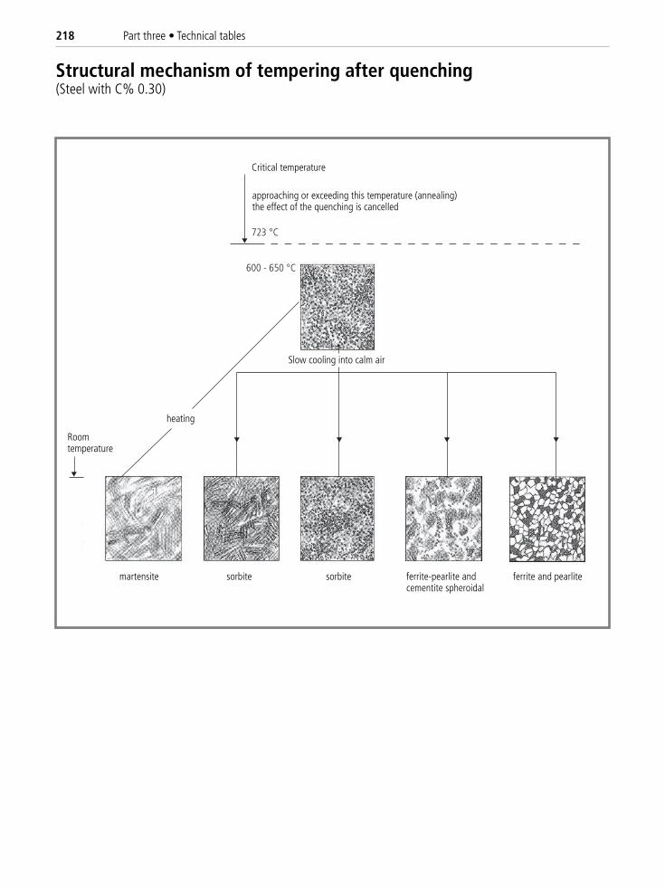
218 Part three • Technical tables
Structural mechanism of tempering after quenching(Steel with C% 0.30)
Critical temperature
approaching or exceeding this temperature (annealing)the effect of the quenching is cancelled
Slow cooling into calm air
heating
martensite sorbite sorbite ferrite and pearlite ferrite-pearlite and cementite spheroidal
Roomtemperature
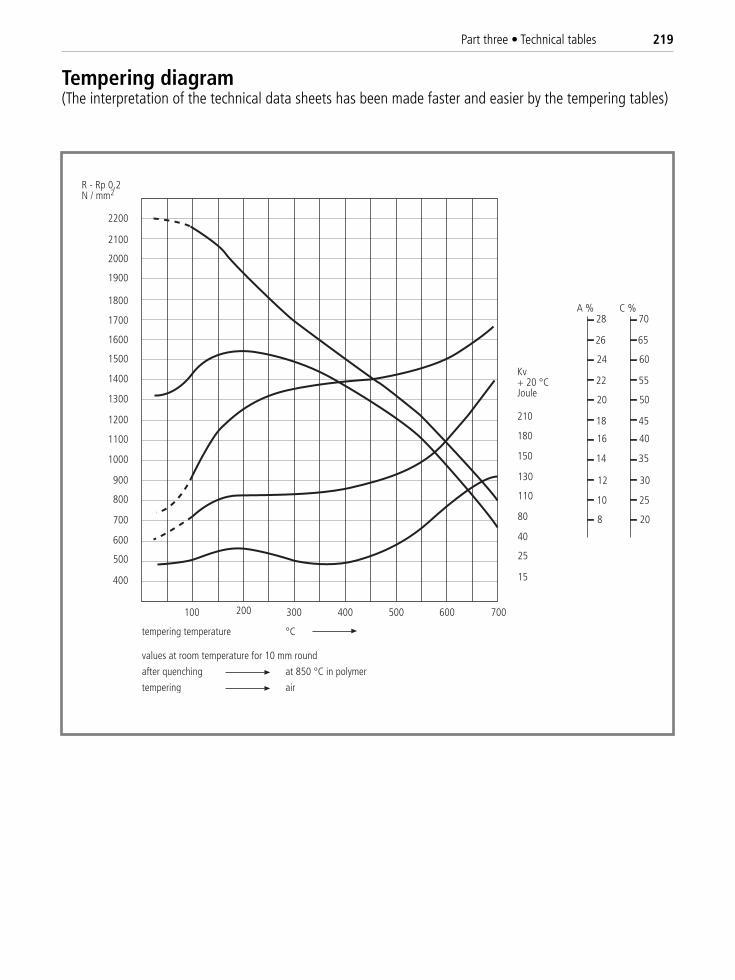
Part three • Technical tables 219
R - Rp 0,2N / mm2
400
500
600
700
800
900
1000
1100
1200
1300
1400
1500
1600
1700
1800
1900
2000
2100
2200
100 200 300 400 500 600 700
tempering temperature °C
values at room temperature for 10 mm round
after quenching at 850 °C in polymer
tempering air
15
25
40
80
110
130
150
180
210
Kv+ 20 °CJoule
28
26
24
22
20
18
16
14
12
10
8
A %70
65
60
55
50
45
40
35
30
25
20
C %
Tempering diagram(The interpretation of the technical data sheets has been made faster and easier by the tempering tables)
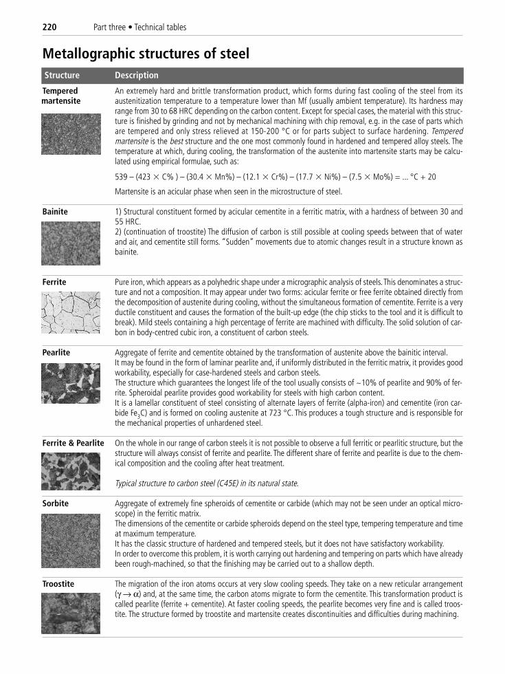
220 Part three • Technical tables
Structure Description
Tempered An extremely hard and brittle transformation product, which forms during fast cooling of the steel from itsaustenitization temperature to a temperature lower than Mf (usually ambient temperature). Its hardness mayrange from 30 to 68 HRC depending on the carbon content. Except for special cases, the material with this struc-ture is finished by grinding and not by mechanical machining with chip removal, e.g. in the case of parts whichare tempered and only stress relieved at 150-200 °C or for parts subject to surface hardening. Temperedmartensite is the best structure and the one most commonly found in hardened and tempered alloy steels. Thetemperature at which, during cooling, the transformation of the austenite into martensite starts may be calcu-lated using empirical formulae, such as:
539 – (423 � C% ) – (30.4 � Mn%) – (12.1 � Cr%) – (17.7 � Ni%) – (7.5 � Mo%) = ... °C + 20
Martensite is an acicular phase when seen in the microstructure of steel.
Bainite 1) Structural constituent formed by acicular cementite in a ferritic matrix, with a hardness of between 30 and55 HRC.2) (continuation of troostite) The diffusion of carbon is still possible at cooling speeds between that of waterand air, and cementite still forms. “Sudden” movements due to atomic changes result in a structure known asbainite.
Ferrite Pure iron, which appears as a polyhedric shape under a micrographic analysis of steels. This denominates a struc-ture and not a composition. It may appear under two forms: acicular ferrite or free ferrite obtained directly fromthe decomposition of austenite during cooling, without the simultaneous formation of cementite. Ferrite is a veryductile constituent and causes the formation of the built-up edge (the chip sticks to the tool and it is difficult tobreak). Mild steels containing a high percentage of ferrite are machined with difficulty. The solid solution of car-bon in body-centred cubic iron, a constituent of carbon steels.
Pearlite Aggregate of ferrite and cementite obtained by the transformation of austenite above the bainitic interval.It may be found in the form of laminar pearlite and, if uniformly distributed in the ferritic matrix, it provides goodworkability, especially for case-hardened steels and carbon steels.The structure which guarantees the longest life of the tool usually consists of ~10% of pearlite and 90% of fer-rite. Spheroidal pearlite provides good workability for steels with high carbon content. It is a lamellar constituent of steel consisting of alternate layers of ferrite (alpha-iron) and cementite (iron car-bide Fe3C) and is formed on cooling austenite at 723 °C. This produces a tough structure and is responsible forthe mechanical properties of unhardened steel.
Ferrite & Pearlite On the whole in our range of carbon steels it is not possible to observe a full ferritic or pearlitic structure, but thestructure will always consist of ferrite and pearlite. The different share of ferrite and pearlite is due to the chem-ical composition and the cooling after heat treatment.
Typical structure to carbon steel (C45E) in its natural state.
Sorbite Aggregate of extremely fine spheroids of cementite or carbide (which may not be seen under an optical micro-scope) in the ferritic matrix.The dimensions of the cementite or carbide spheroids depend on the steel type, tempering temperature and timeat maximum temperature.It has the classic structure of hardened and tempered steels, but it does not have satisfactory workability.In order to overcome this problem, it is worth carrying out hardening and tempering on parts which have alreadybeen rough-machined, so that the finishing may be carried out to a shallow depth.
Troostite The migration of the iron atoms occurs at very slow cooling speeds. They take on a new reticular arrangement (γ → α) and, at the same time, the carbon atoms migrate to form the cementite. This transformation product iscalled pearlite (ferrite + cementite). At faster cooling speeds, the pearlite becomes very fine and is called troos-tite. The structure formed by troostite and martensite creates discontinuities and difficulties during machining.
martensite
Metallographic structures of steel

Part three • Technical tables 221
Cementite Iron carbide with formula Fe3C. It is a chemical combination of iron and carbon, with a content of C = 6.70%.It has ferromagnetic properties below 210 °C. It is a very hard but extremely brittle crystalline substance. It maybe broken down into ferrite and graphitic carbon by extremely slow cooling.Its hardness may reach as much as 63 HRc.It may be:• primary when it is formed by the direct separation of the liquid• secondary when it separates from austenite• tertiary when it separates from ferrite
The morphologic appearance may be: spheroidized, lamellar and acicular.
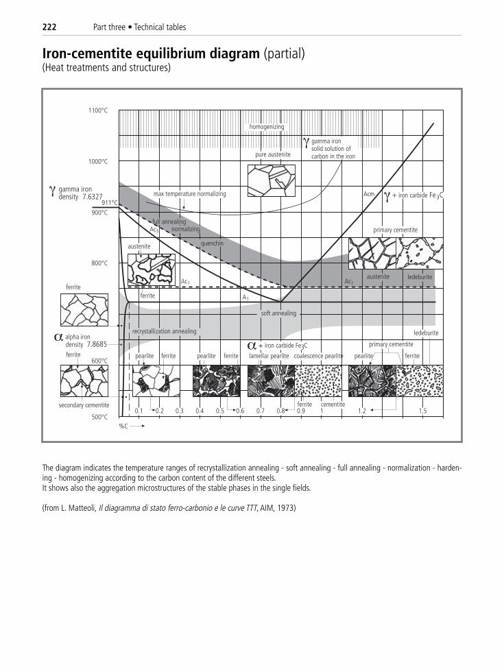
222 Part three • Technical tables
homogenizing
Acm
pure austenite
austenite ledeburiteAc1
A1
Ac1
austenite
Ac3
recrystallization annealing
soft annealing
ferrite
ferrite
secondary cementite
pearlite ferrite pearlite ferrite lamellar pearlite coalescence pearlite
ferrite cementite
pearlite ferrite
primary cementite
ledeburite
max temperature normalizing
ferrite
%C
0.1 0.30.2 0.4 0.5 0.6 0.7 0.8 0.9 1 1.2 1,5
iron carbide Fe3C
+ iron carbide Fe3C
gamma iron solid solution of carbon in the iron
quenchin
full annealingnormalizing
gamma iron density 7.6327
alpha iron density 7.8685
primary cementite
Iron-cementite equilibrium diagram (partial)(Heat treatments and structures)
The diagram indicates the temperature ranges of recrystallization annealing - soft annealing - full annealing - normalization - harden-ing - homogenizing according to the carbon content of the different steels.It shows also the aggregation microstructures of the stable phases in the single fields.
(from L. Matteoli, Il diagramma di stato ferro-carbonio e le curve TTT, AIM, 1973)
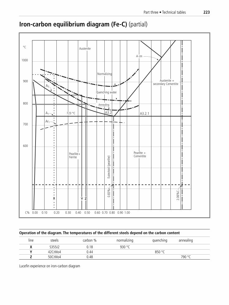
Part three • Technical tables 223
1000
900
800
700
600
Pearlite +Ferrite
Pearlite +Cementite
Austenite +secondary Cementite
Austenite
A cm
A3
A1
Ar1
A3.2 A3.2.1
Y Z
Normalizing
Quenching water
AnnealingEu
tect
oid
(pea
rlite
)0.
83%
c
2.06
%C
0.00 0.10 0.20 0.30 0.40 0.50 0.60 0.70 0.80 0.90 1.00C%
X
Iron-carbon equilibrium diagram (Fe-C) (partial)
Operation of the diagram. The temperatures of the different steels depend on the carbon content
line steels carbon % normalizing quenching annealing
X S355J2 0.18 930 °CY 42CrMo4 0.44 850 °CZ 50CrMo4 0.48 790 °C
Lucefin experience on iron-carbon diagram
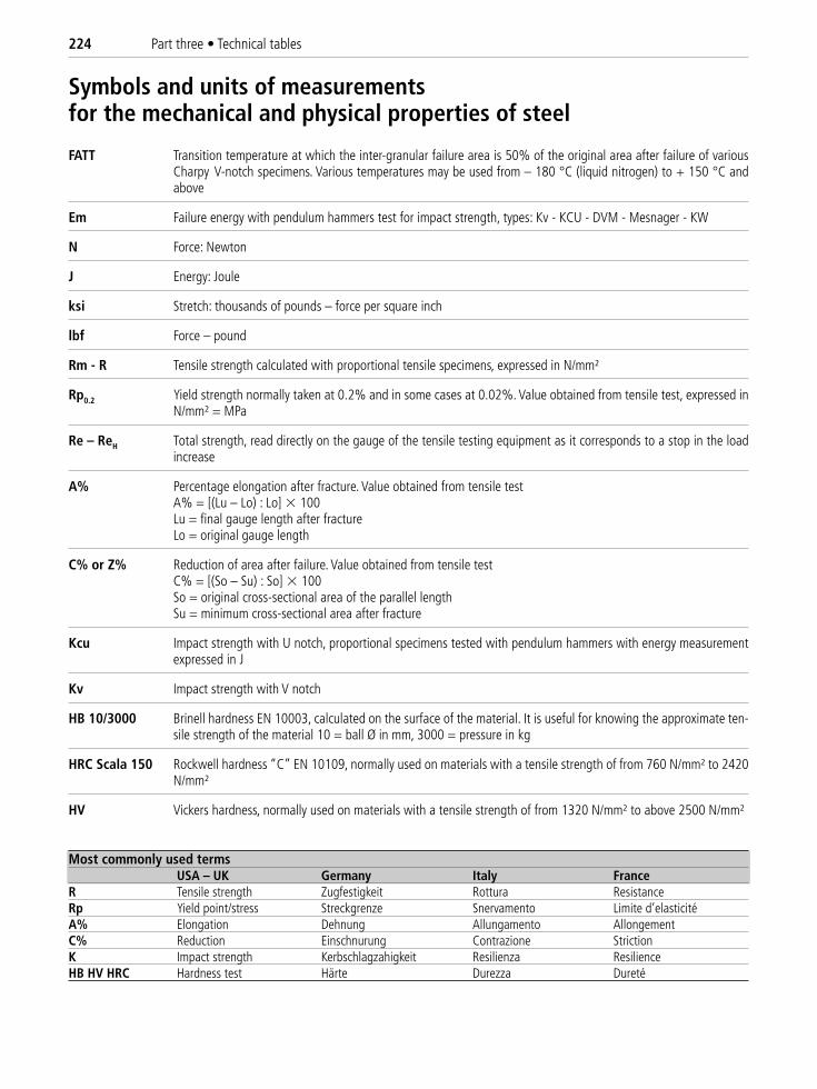
224 Part three • Technical tables
FATT Transition temperature at which the inter-granular failure area is 50% of the original area after failure of variousCharpy V-notch specimens. Various temperatures may be used from – 180 °C (liquid nitrogen) to + 150 °C andabove
Em Failure energy with pendulum hammers test for impact strength, types: Kv - KCU - DVM - Mesnager - KW
N Force: Newton
J Energy: Joule
ksi Stretch: thousands of pounds – force per square inch
lbf Force – pound
Rm - R Tensile strength calculated with proportional tensile specimens, expressed in N/mm²
Rp0.2 Yield strength normally taken at 0.2% and in some cases at 0.02%. Value obtained from tensile test, expressed inN/mm² = MPa
Re – ReH Total strength, read directly on the gauge of the tensile testing equipment as it corresponds to a stop in the loadincrease
A% Percentage elongation after fracture. Value obtained from tensile testA% = [(Lu – Lo) : Lo] � 100Lu = final gauge length after fractureLo = original gauge length
C% or Z% Reduction of area after failure. Value obtained from tensile testC% = [(So – Su) : So] � 100So = original cross-sectional area of the parallel lengthSu = minimum cross-sectional area after fracture
Kcu Impact strength with U notch, proportional specimens tested with pendulum hammers with energy measurementexpressed in J
Kv Impact strength with V notch
HB 10/3000 Brinell hardness EN 10003, calculated on the surface of the material. It is useful for knowing the approximate ten-sile strength of the material 10 = ball Ø in mm, 3000 = pressure in kg
HRC Scala 150 Rockwell hardness “C” EN 10109, normally used on materials with a tensile strength of from 760 N/mm² to 2420N/mm²
HV Vickers hardness, normally used on materials with a tensile strength of from 1320 N/mm² to above 2500 N/mm²
Most commonly used termsUSA – UK Germany Italy France
R Tensile strength Zugfestigkeit Rottura ResistanceRp Yield point/stress Streckgrenze Snervamento Limite d’elasticité A% Elongation Dehnung Allungamento Allongement C% Reduction Einschnurung Contrazione Striction K Impact strength Kerbschlagzahigkeit Resilienza Resilience HB HV HRC Hardness test Härte Durezza Dureté
Symbols and units of measurements for the mechanical and physical properties of steel
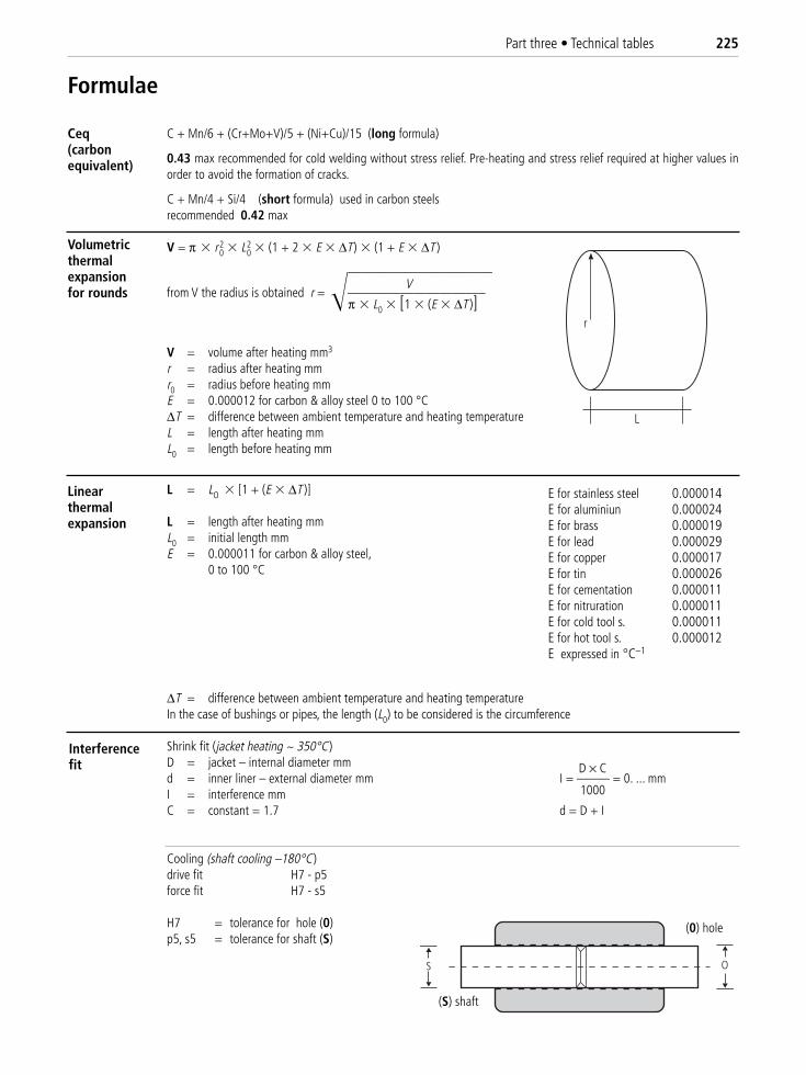
Part three • Technical tables 225
C + Mn/6 + (Cr+Mo+V)/5 + (Ni+Cu)/15 (long formula)
0.43 max recommended for cold welding without stress relief. Pre-heating and stress relief required at higher values inorder to avoid the formation of cracks.
C + Mn/4 + Si/4 (short formula) used in carbon steelsrecommended 0.42 max
V = π � r 20 � L2
0 � (1 + 2 � E � ΔT) � (1 + E � ΔT )
———————————V
from V the radius is obtained r = �—————————–––π � L0 � [1 � (E � ΔT )]
V = volume after heating mm3
r = radius after heating mmr0 = radius before heating mmE = 0.000012 for carbon & alloy steel 0 to 100 °CΔT = difference between ambient temperature and heating temperatureL = length after heating mmL0 = length before heating mm
L = LO � [1 + (E � ΔT )]
L = length after heating mmL0 = initial length mmE = 0.000011 for carbon & alloy steel,
0 to 100 °C
ΔT = difference between ambient temperature and heating temperatureIn the case of bushings or pipes, the length (L0) to be considered is the circumference
Shrink fit (jacket heating ~ 350°C)D = jacket – internal diameter mm D × Cd = inner liner – external diameter mm I = ––––– = 0. ... mmI = interference mm 1000
C = constant = 1.7 d = D + I
Cooling (shaft cooling –180°C)drive fit H7 - p5force fit H7 - s5
H7 = tolerance for hole (0)p5, s5 = tolerance for shaft (S)
Formulae
Ceq(carbonequivalent)
Volumetricthermalexpansionfor rounds
Linearthermalexpansion
E for stainless steel 0.000014E for aluminiun 0.000024E for brass 0.000019E for lead 0.000029E for copper 0.000017E for tin 0.000026E for cementation 0.000011E for nitruration 0.000011E for cold tool s. 0.000011E for hot tool s. 0.000012E expressed in °C–1
r
L
Interferencefit
O=foro
O
S=albero
S
(0) hole
(S) shaft

226 Part three • Technical tables
SpForged and hot-rolled ––– = ... : 1 (direct deformation)
Sf
Sp = ingot/bloom/billet cross-section Sf = end product cross-sectionForged ≥ 3.5: 1Hot-Rolled ≥ 6: 1
(Sp – Sc)Forged and Hot-Rolled –––––––– = ...%
Sf
Sf = hot-rolled section Sc = cold-drawn/cold-rolled section
Calculation of critical points on the basis of the chemical composition of the steel expressed in %.The result is given in °C and enables the technicians to determine the heat treatment parameters.The formulae are valid for steels with C% 0.60 max and alloys with a max content of 5% each.
Temperature at which, during heating, the formation of Austenite starts.
723 – 10.7Mn – 16.9Ni + 30Si + 16.9Cr + 25Mo + 6.38 W + 30Al + 50V + 290As =.... °C ± 10
The equation is valid only for medium-alloyed steels.
Temperature at which, during heating, the transformation of Ferrite into austenite stops.—
910 – 203 �C – 15.2Ni – 30Mn – 11Cr – 20Cu + 44.7Si + 104V + 31.5Mo + 13.1W + 700P + 400Al = ... °C + 10
The equation is valid only for medium-alloyed steels.
Temperature at which, during cooling, the transformation of austenite into Martensite starts.
539 – (423 � C% ) – (30.4 � Mn%) – (12.1 � Cr%) – (17.7 � Ni%) – (7.5 � Mo%) = … °C + 20
The equation is valid for steels:C% 0.10-0.55 Mn% 0.20-1.70 Si% < 0.35 Ni% < 5.00 Cr% < 3.50 Mo% < 1.00
Temperature at which the transformation of austenite into martensite is complete (martensite finish).
Mf = Ms – 215 °C (± 15°C)
Reductionratio(r.r.)
Ac1 (°C)
Ac3 (°C)
Ms (°C)
Mf (°C)
Comparison mechanical Properties Alloys and Steels*titanium carbon micro-alloyed stainless alloy superalloy
BT 6 GR 5 Al (2024) (Hastelloy)Density g/cm3 4.4 7.8 7.8 7.9 3 8.9R N/mm2 980 460 710 610 460 550Rp N/mm2 850 300 560 480 350 330A % % 14 28 24 50 9 15Thermal cond. W ⋅ m–1⋅°C–1 21 55 75 30 200 60Melting range °C 1650 1440 1440 1480 660 1580* Approximate values
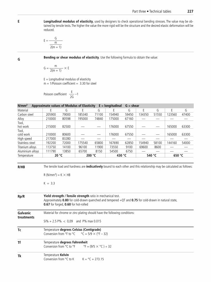
Part three • Technical tables 227
Longitudinal modulus of elasticity, used by designers to check operational bending stresses. The value may be ob-tained by tensile tests. The higher the value the more rigid will be the structure and the desired elastic deformation will bereduced.
GE = ————m———–
2(m + 1)
Bending or shear modulus of elasticity. Use the following formula to obtain the value:
mG = ———— � E
2(m + 1)
E = Longitudinal modulus of elasticitym = 1/Poisson coefficient = 3.30 for steel
EPoisson coefficient ––– –1
2G
The tensile load and hardness are indicatively bound to each other and this relationship may be calculated as follows:
R (N/mm2) = K � HB
K = 3.3
Yield strength / Tensile strength ratio in mechanical test.Approximately 0.80 for cold-drawn quenched and tempered +QT and 0.75 for cold-drawn in natural state, 0.67 for forged, 0.60 for hot-rolled
Material for chrome or zinc-plating should have the following conditions:
Si% + 2.5 P% < 0,09 and P% max 0.015
Temperature degrees Celsius (Centigrade)Conversion from °F to °C °C = 5/9 � (°F – 32)
Temperature degrees FahrenheitConversion from °C to °F °F = (9/5 � °C ) + 32
Temperature KelvinConversion from °C to K K = °C + 273.15
N/mm2 Approximate values of Modulus of Elasticity E = longitudinal G = shearMaterial E G E G E G E G E GCarbon steel 205900 79000 185340 71100 154940 59450 134350 51550 123560 47400Alloy 210000 80598 195000 74840 175000 67160 — — — —Tool, hot work 215000 82500 — — 176000 67550 — — 165000 63300Tool,cold work 210000 80600 — — 176000 67550 — — 165000 63300High-speed 217000 83280 — — — — — — — —Stainless steel 192200 72000 175540 65800 167690 62850 154940 58100 144160 54000Titanium alloys 113750 14100 96100 11900 73550 9100 69600 8600 — —Aluminium alloys 111790 13850 65700 8150 54500 6750 — — — —Temperature 20 °C 200 °C 430 °C 540 °C 650 °C
E
G
R/HB
Rp/R
Galvanictreatments
Tk
Tc
Tf
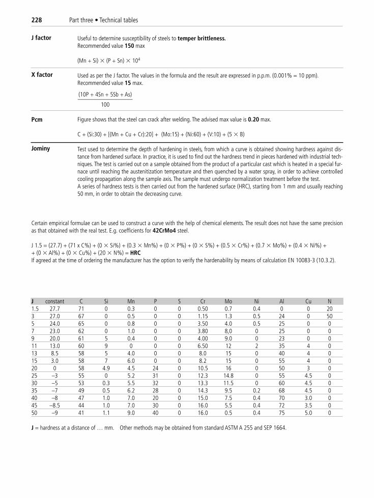
228 Part three • Technical tables
Useful to determine susceptibility of steels to temper brittleness.Recommended value 150 max
(Mn + Si) � (P + Sn) � 104
Used as per the J factor. The values in the formula and the result are expressed in p.p.m. (0.001% = 10 ppm).Recommended value 15 max.
(10P + 4Sn + 5Sb + As)––––––––––––––––––
100
Figure shows that the steel can crack after welding. The advised max value is 0.20 max.
C + (Si:30) + [(Mn + Cu + Cr):20] + (Mo:15) + (Ni:60) + (V:10) + (5 � B)
Test used to determine the depth of hardening in steels, from which a curve is obtained showing hardness against dis-tance from hardened surface. In practice, it is used to find out the hardness trend in pieces hardened with industrial tech-niques. The test is carried out on a sample obtained from the product of a particular cast which is heated in a special fur-nace until reaching the austenitization temperature and then quenched by a water spray, in order to achieve controlledcooling propagation along the sample axis. The sample must undergo normalization treatment before the test.A series of hardness tests is then carried out from the hardened surface (HRC), starting from 1 mm and usually reaching50 mm, in order to obtain the decreasing curve.
J constant C Si Mn P S Cr Mo Ni Al Cu N1.5 27.7 71 0 0.3 0 0 0.50 0.7 0.4 0 0 203 27.0 67 0 0.5 0 0 1.15 1.3 0.5 24 0 505 24.0 65 0 0.8 0 0 3.50 4.0 0.5 25 0 07 23.0 62 0 1.0 0 0 3.80 8,0 0 25 0 09 20.0 61 5 0.4 0 0 4.00 9.0 0 23 0 011 13.0 60 9 0 0 0 6.50 12 2 35 4 013 8.5 58 5 4.0 0 0 8.0 15 0 40 4 015 3.0 58 7 6.0 0 0 8.2 15 0 55 4 020 0 58 4.9 4.5 24 0 10.5 16 0 50 3 025 –3 55 0 5.2 31 0 12.3 14.8 0 55 4.5 030 –5 53 0.3 5.5 32 0 13.3 11.5 0 60 4.5 035 –7 49 0.5 6.2 28 0 14.3 9.5 0.2 68 4.5 040 –8 47 1.0 7.0 20 0 15.0 7.5 0.4 70 3.0 045 –8.5 44 1.0 7.0 30 0 16.0 5.5 0.4 72 3.5 050 –9 41 1.1 9.0 40 0 16.0 0.5 0.4 75 5.0 0
J = hardness at a distance of … mm. Other methods may be obtained from standard ASTM A 255 and SEP 1664.
J factor
X factor
Certain empirical formulae can be used to construct a curve with the help of chemical elements. The result does not have the same precisionas that obtained with the real test. E.g. coefficients for 42CrMo4 steel.
J 1.5 = (27.7) + (71 x C%) + (0 � Si%) + (0.3 � Mn%) + (0 � P%) + (0 � S%) + (0.5 � Cr%) + (0.7 � Mo%) + (0.4 � Ni%) + + (0 � Al%) + (0 � Cu%) + (20 � N%) = HRCIf agreed at the time of ordering the manufacturer has the option to verify the hardenability by means of calculation EN 10083-3 (10.3.2).
Pcm
Jominy

Part three • Technical tables 229
Hardenability curveThe hardenability of a steel increases the greater the hardness ismaintained with an increase in the distance “d”
Quenched end
100 mm25 mm
12.5 mm H2O 20¡C
HRC
“d”
mm
0 11 25 35 50 60 80 100
time
martensite 100%
mm0 11 25 35 50 60 80
martensite 80%+ ferrite - bainite
martensite 20%+ ferrite - bainite
martensite 50%+ ferrite - bainite
austenite +pearlite
860
810
760
705
640
585
530
475
420
365
310
255
200
austenite + martensite
austenite + bainite
austenite + ferrite
Distance in mm from quenched end
Hardenability = aptitude of a steel to undergo a more or lesscomplete transformation into a martensitic structure for a samplewith determined dimensions and geometry.
Structures obtained withthe Jominy test
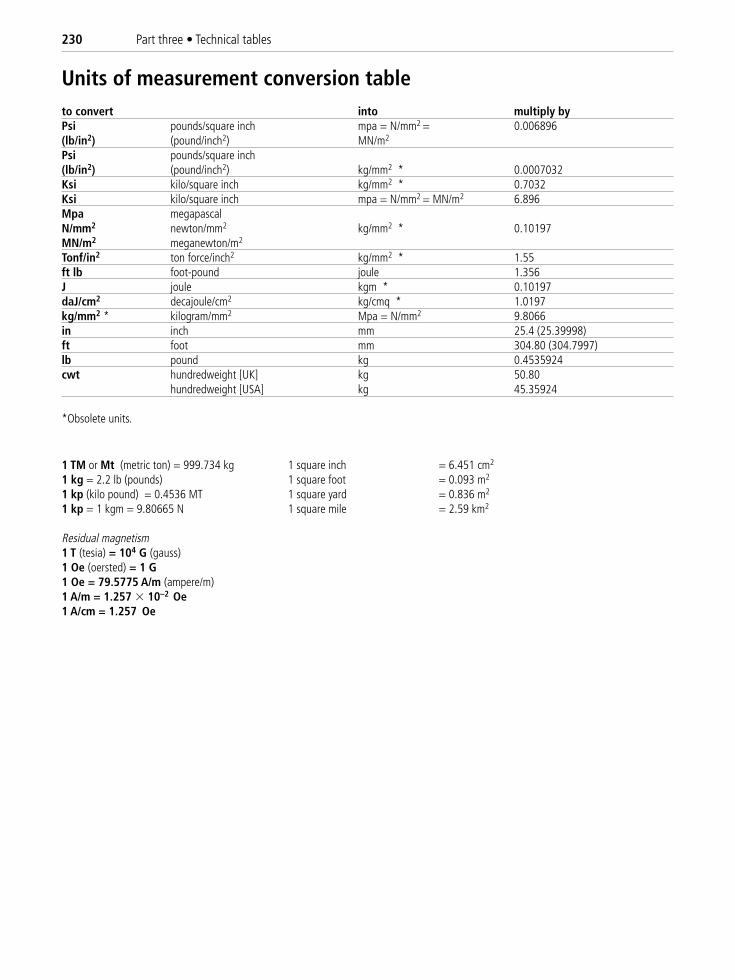
230 Part three • Technical tables
Units of measurement conversion table to convert into multiply byPsi pounds/square inch mpa = N/mm2 = 0.006896(lb/in2) (pound/inch2) MN/m2
Psi pounds/square inch(lb/in2) (pound/inch2) kg/mm2 * 0.0007032Ksi kilo/square inch kg/mm2 * 0.7032Ksi kilo/square inch mpa = N/mm2 = MN/m2 6.896Mpa megapascal N/mm2 newton/mm2 kg/mm2 * 0.10197MN/m2 meganewton/m2
Tonf/in2 ton force/inch2 kg/mm2 * 1.55ft lb foot-pound joule 1.356J joule kgm * 0.10197daJ/cm2 decajoule/cm2 kg/cmq * 1.0197kg/mm2 * kilogram/mm2 Mpa = N/mm2 9.8066in inch mm 25.4 (25.39998)ft foot mm 304.80 (304.7997)lb pound kg 0.4535924cwt hundredweight [UK] kg 50.80
hundredweight [USA] kg 45.35924
*Obsolete units.
1 TM or Mt (metric ton) = 999.734 kg 1 square inch = 6.451 cm2
1 kg = 2.2 lb (pounds) 1 square foot = 0.093 m2
1 kp (kilo pound) = 0.4536 MT 1 square yard = 0.836 m2
1 kp = 1 kgm = 9.80665 N 1 square mile = 2.59 km2
Residual magnetism 1 T (tesia) = 104 G (gauss)1 Oe (oersted) = 1 G1 Oe = 79.5775 A/m (ampere/m)1 A/m = 1.257 � 10–2 Oe1 A/cm = 1.257 Oe
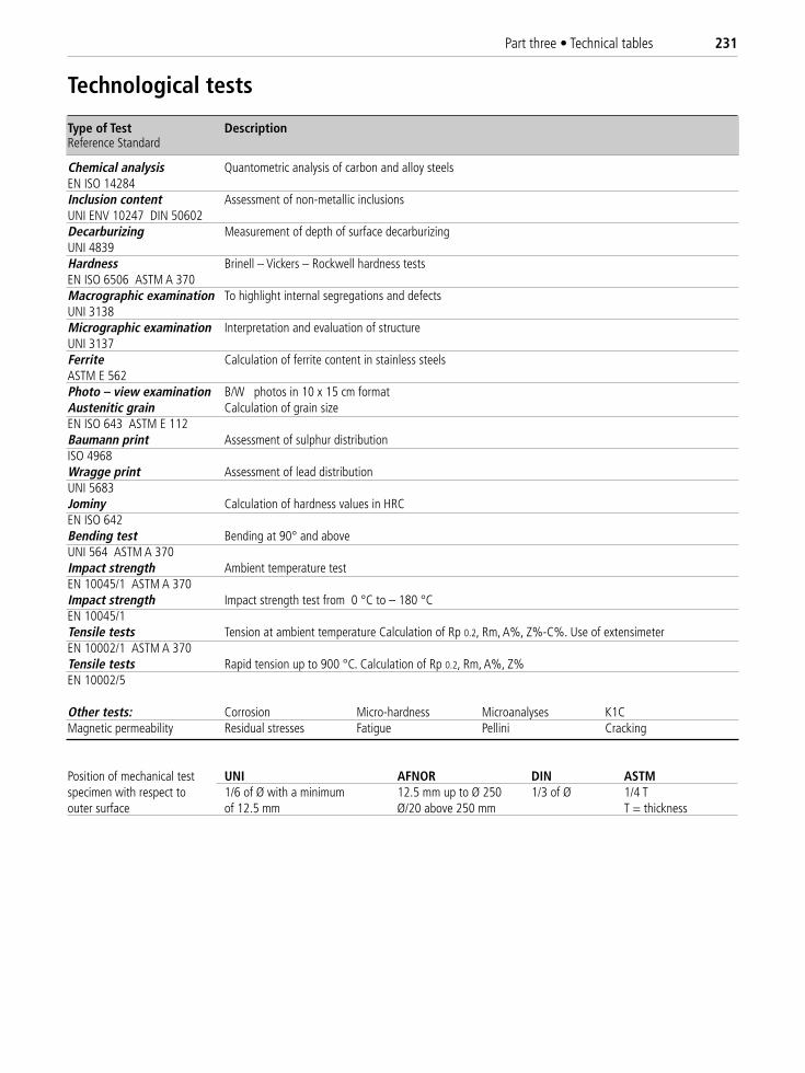
Part three • Technical tables 231
Technological tests
Type of Test DescriptionReference Standard
Chemical analysis Quantometric analysis of carbon and alloy steelsEN ISO 14284Inclusion content Assessment of non-metallic inclusionsUNI ENV 10247 DIN 50602Decarburizing Measurement of depth of surface decarburizingUNI 4839Hardness Brinell – Vickers – Rockwell hardness testsEN ISO 6506 ASTM A 370Macrographic examination To highlight internal segregations and defectsUNI 3138Micrographic examination Interpretation and evaluation of structureUNI 3137Ferrite Calculation of ferrite content in stainless steelsASTM E 562Photo – view examination B/W photos in 10 x 15 cm formatAustenitic grain Calculation of grain sizeEN ISO 643 ASTM E 112Baumann print Assessment of sulphur distribution ISO 4968Wragge print Assessment of lead distributionUNI 5683Jominy Calculation of hardness values in HRCEN ISO 642Bending test Bending at 90° and aboveUNI 564 ASTM A 370Impact strength Ambient temperature test EN 10045/1 ASTM A 370Impact strength Impact strength test from 0 °C to – 180 °CEN 10045/1Tensile tests Tension at ambient temperature Calculation of Rp 0.2, Rm, A%, Z%-C%. Use of extensimeterEN 10002/1 ASTM A 370Tensile tests Rapid tension up to 900 °C. Calculation of Rp 0.2, Rm, A%, Z%EN 10002/5
Other tests: Corrosion Micro-hardness Microanalyses K1CMagnetic permeability Residual stresses Fatigue Pellini Cracking
Position of mechanical test UNI AFNOR DIN ASTMspecimen with respect to 1/6 of Ø with a minimum 12.5 mm up to Ø 250 1/3 of Ø 1/4 Touter surface of 12.5 mm Ø/20 above 250 mm T = thickness
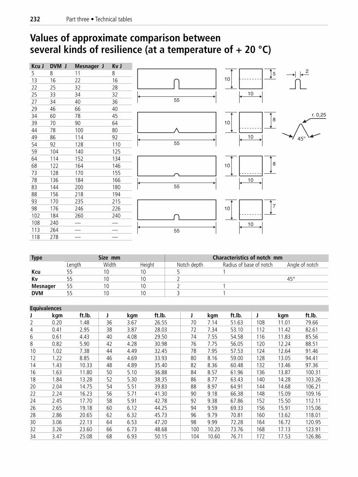
232 Part three • Technical tables
Values of approximate comparison betweenseveral kinds of resilience (at a temperature of + 20 °C)Kcu J DVM J Mesnager J Kv J5 8 11 813 16 22 1622 25 32 2825 33 34 3227 34 40 3629 46 66 4034 60 78 4539 70 90 6444 78 100 8049 86 114 9254 92 128 11059 104 140 12564 114 152 13468 122 164 14673 128 170 15578 136 184 16683 144 200 18088 156 218 19493 170 235 21598 176 246 226102 184 260 240108 240 — —113 264 — —118 278 — —
45°
Type Size mm Characteristics of notch mmLength Width Height Notch depth Radius of base of notch Angle of notch
Kcu 55 10 10 5 1Kv 55 10 10 2 45°Mesnager 55 10 10 2 1DVM 55 10 10 3 1
EquivalencesJ kgm ft.lb. J kgm ft.lb. J kgm ft.lb. J kgm ft.lb.2 0.20 1.48 36 3.67 26.55 70 7.14 51.63 108 11.01 79.664 0.41 2.95 38 3.87 28.03 72 7.34 53.10 112 11.42 82.616 0.61 4.43 40 4.08 29.50 74 7.55 54.58 116 11.83 85.568 0.82 5.90 42 4.28 30.98 76 7.75 56.05 120 12.24 88.5110 1.02 7.38 44 4.49 32.45 78 7.95 57.53 124 12.64 91.4612 1.22 8.85 46 4.69 33.93 80 8.16 59.00 128 13.05 94.4114 1.43 10.33 48 4.89 35.40 82 8.36 60.48 132 13.46 97.3616 1.63 11.80 50 5.10 36.88 84 8.57 61.96 136 13.87 100.3118 1.84 13.28 52 5.30 38.35 86 8.77 63.43 140 14.28 103.2620 2.04 14.75 54 5.51 39.83 88 8.97 64.91 144 14.68 106.2122 2.24 16.23 56 5.71 41.30 90 9.18 66.38 148 15.09 109.1624 2.45 17.70 58 5.91 42.78 92 9.38 67.86 152 15.50 112.1126 2.65 19.18 60 6.12 44.25 94 9.59 69.33 156 15.91 115.0628 2.86 20.65 62 6.32 45.73 96 9.79 70.81 160 13.62 118.0130 3.06 22.13 64 6.53 47.20 98 9.99 72.28 164 16.72 120.9532 3.26 23.60 66 6.73 48.68 100 10.20 73.76 168 17.13 123.9134 3.47 25.08 68 6.93 50.15 104 10.60 76.71 172 17.53 126.86
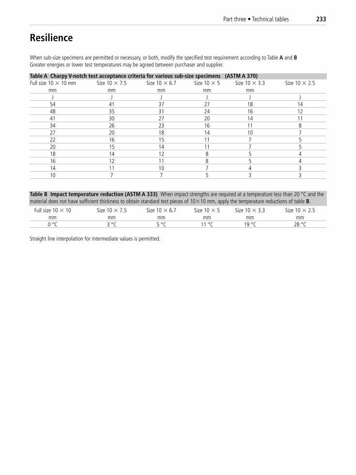
Part three • Technical tables 233
When sub-size specimens are permitted or necessary, or both, modify the specified test requirement according to Table A and BGreater energies or lower test temperatures may be agreed between purchaser and supplier.
Table A Charpy V-notch test acceptance criteria for various sub-size specimens (ASTM A 370)Full size 10 � 10 mm Size 10 � 7.5 Size 10 � 6.7 Size 10 � 5 Size 10 � 3.3 Size 10 � 2.5
mm mm mm mm mmJ J J J J J
54 41 37 27 18 1448 35 31 24 16 1241 30 27 20 14 1134 26 23 16 11 827 20 18 14 10 722 16 15 11 7 520 15 14 11 7 518 14 12 8 5 416 12 11 8 5 414 11 10 7 4 310 7 7 5 3 3
Table B Impact temperature reduction (ASTM A 333) When impact strengths are required at a temperature less than 20 °C and thematerial does not have sufficient thickness to obtain standard test pieces of 10�10 mm, apply the temperature reductions of table B.
Full size 10 � 10 Size 10 � 7.5 Size 10 � 6.7 Size 10 � 5 Size 10 � 3.3 Size 10 � 2.5mm mm mm mm mm mm0 °C 3 °C 5 °C 11 °C 19 °C 28 °C
Straight line interpolation for intermediate values is permitted.
Resilience
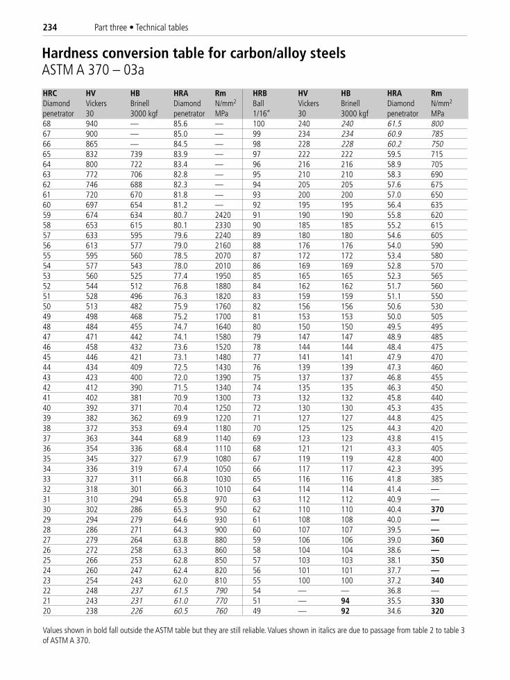
234 Part three • Technical tables
HRC HV HB HRA Rm HRB HV HB HRA RmDiamond Vickers Brinell Diamond N/mm2 Ball Vickers Brinell Diamond N/mm2
penetrator 30 3000 kgf penetrator MPa 1/16’’ 30 3000 kgf penetrator MPa68 940 — 85.6 — 100 240 240 61.5 80067 900 — 85.0 — 99 234 234 60.9 78566 865 — 84.5 — 98 228 228 60.2 75065 832 739 83.9 — 97 222 222 59.5 71564 800 722 83.4 — 96 216 216 58.9 70563 772 706 82.8 — 95 210 210 58.3 69062 746 688 82.3 — 94 205 205 57.6 67561 720 670 81.8 — 93 200 200 57.0 65060 697 654 81.2 — 92 195 195 56.4 63559 674 634 80.7 2420 91 190 190 55.8 62058 653 615 80.1 2330 90 185 185 55.2 61557 633 595 79.6 2240 89 180 180 54.6 60556 613 577 79.0 2160 88 176 176 54.0 59055 595 560 78.5 2070 87 172 172 53.4 58054 577 543 78.0 2010 86 169 169 52.8 57053 560 525 77.4 1950 85 165 165 52.3 56552 544 512 76.8 1880 84 162 162 51.7 56051 528 496 76.3 1820 83 159 159 51.1 55050 513 482 75.9 1760 82 156 156 50.6 53049 498 468 75.2 1700 81 153 153 50.0 50548 484 455 74.7 1640 80 150 150 49.5 49547 471 442 74.1 1580 79 147 147 48.9 48546 458 432 73.6 1520 78 144 144 48.4 47545 446 421 73.1 1480 77 141 141 47.9 47044 434 409 72.5 1430 76 139 139 47.3 46043 423 400 72.0 1390 75 137 137 46.8 45542 412 390 71.5 1340 74 135 135 46.3 45041 402 381 70.9 1300 73 132 132 45.8 44040 392 371 70.4 1250 72 130 130 45.3 43539 382 362 69.9 1220 71 127 127 44.8 42538 372 353 69.4 1180 70 125 125 44.3 42037 363 344 68.9 1140 69 123 123 43.8 41536 354 336 68.4 1110 68 121 121 43.3 40535 345 327 67.9 1080 67 119 119 42.8 40034 336 319 67.4 1050 66 117 117 42.3 39533 327 311 66.8 1030 65 116 116 41.8 38532 318 301 66.3 1010 64 114 114 41.4 —31 310 294 65.8 970 63 112 112 40.9 —30 302 286 65.3 950 62 110 110 40.4 37029 294 279 64.6 930 61 108 108 40.0 —28 286 271 64.3 900 60 107 107 39.5 —27 279 264 63.8 880 59 106 106 39.0 36026 272 258 63.3 860 58 104 104 38.6 —25 266 253 62.8 850 57 103 103 38.1 35024 260 247 62.4 820 56 101 101 37.7 —23 254 243 62.0 810 55 100 100 37.2 34022 248 237 61.5 790 54 — — 36.8 —21 243 231 61.0 770 51 — 94 35.5 33020 238 226 60.5 760 49 — 92 34.6 320
Hardness conversion table for carbon/alloy steelsASTM A 370 – 03a
Values shown in bold fall outside the ASTM table but they are still reliable. Values shown in italics are due to passage from table 2 to table 3of ASTM A 370.
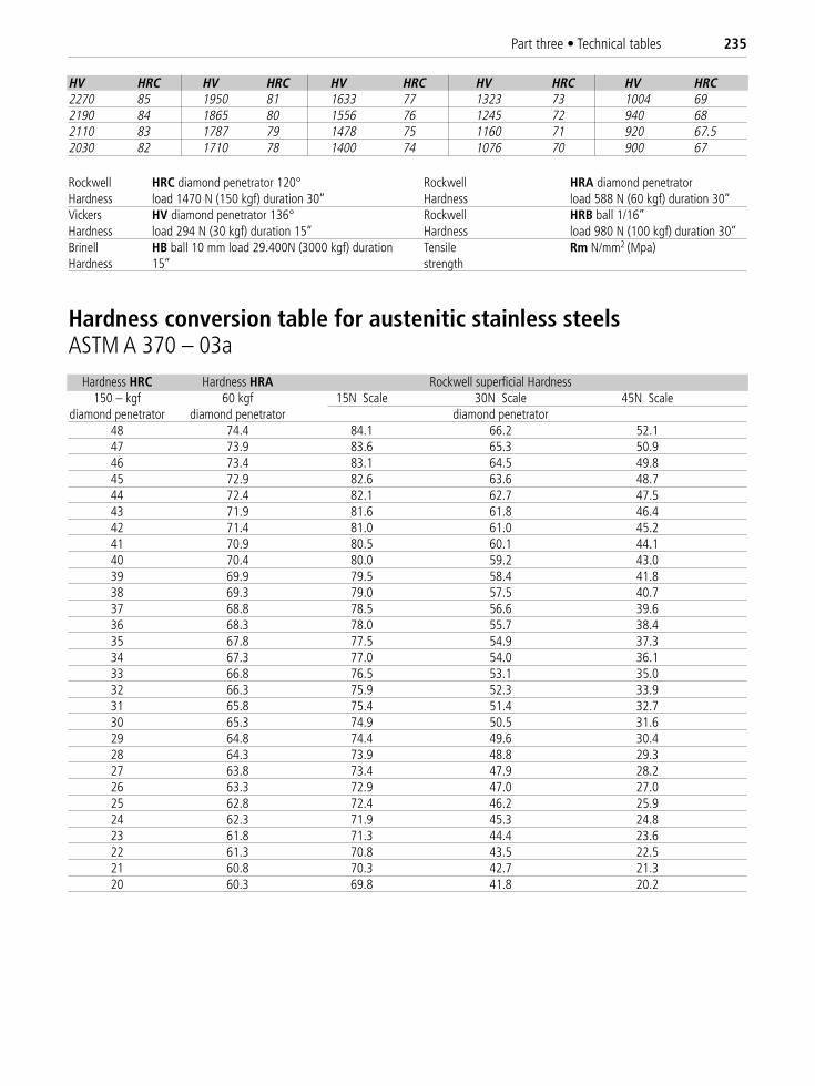
Part three • Technical tables 235
HV HRC HV HRC HV HRC HV HRC HV HRC2270 85 1950 81 1633 77 1323 73 1004 692190 84 1865 80 1556 76 1245 72 940 682110 83 1787 79 1478 75 1160 71 920 67.52030 82 1710 78 1400 74 1076 70 900 67
Rockwell HRC diamond penetrator 120° Rockwell HRA diamond penetratorHardness load 1470 N (150 kgf) duration 30’’ Hardness load 588 N (60 kgf) duration 30’’Vickers HV diamond penetrator 136° Rockwell HRB ball 1/16’’Hardness load 294 N (30 kgf) duration 15’’ Hardness load 980 N (100 kgf) duration 30’’Brinell HB ball 10 mm load 29.400N (3000 kgf) duration Tensile Rm N/mm2 (Mpa)Hardness 15’’ strength
Hardness HRC Hardness HRA Rockwell superficial Hardness150 – kgf 60 kgf 15N Scale 30N Scale 45N Scale
diamond penetrator diamond penetrator diamond penetrator48 74.4 84.1 66.2 52.147 73.9 83.6 65.3 50.946 73.4 83.1 64.5 49.845 72.9 82.6 63.6 48.744 72.4 82.1 62.7 47.543 71.9 81.6 61.8 46.442 71.4 81.0 61.0 45.241 70.9 80.5 60.1 44.140 70.4 80.0 59.2 43.039 69.9 79.5 58.4 41.838 69.3 79.0 57.5 40.737 68.8 78.5 56.6 39.636 68.3 78.0 55.7 38.435 67.8 77.5 54.9 37.334 67.3 77.0 54.0 36.133 66.8 76.5 53.1 35.032 66.3 75.9 52.3 33.931 65.8 75.4 51.4 32.730 65.3 74.9 50.5 31.629 64.8 74.4 49.6 30.428 64.3 73.9 48.8 29.327 63.8 73.4 47.9 28.226 63.3 72.9 47.0 27.025 62.8 72.4 46.2 25.924 62.3 71.9 45.3 24.823 61.8 71.3 44.4 23.622 61.3 70.8 43.5 22.521 60.8 70.3 42.7 21.320 60.3 69.8 41.8 20.2
Hardness conversion table for austenitic stainless steelsASTM A 370 – 03a
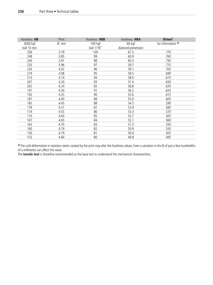
236 Part three • Technical tables
Hardness HB Print Hardness HRB Hardness HRA N/mm2
3000 kgf Ø mm 100 kgf 60 kgf for information a)
ball 10 mm ball 1/16’’ diamond penetrator256 3.79 100 61.5 770248 3.85 99 60.9 760240 3.91 98 60.3 750233 3.96 97 59.7 715226 4.02 96 59.1 705219 4.08 95 58.5 690213 4.14 94 58.0 675207 4.20 93 57.4 650202 4.24 92 56.8 635197 4.30 91 56.2 620192 4.35 90 55.6 615187 4.40 89 55.0 605183 4.45 88 54.5 590178 4.51 87 53.9 580174 4.55 86 53.3 570170 4.60 85 52.7 565167 4.65 84 52.1 560163 4.70 83 51.5 550160 4.74 82 50.9 530156 4.79 81 50.4 505153 4.84 80 49.8 495
a) The cold deformation in stainless steels created by the print may alter the hardness values. Even a variation in the Ø of just a few hundredthsof a millimetre can affect the value.The tensile test is therefore recommended as the base test to understand the mechanical characteristics.
All information contained in this manual has been carefully verified. The authors, the publisher and Lucefin reject any responsability for its use.