steel, iron and aluminium workengineeringprojects.com/tender/uploadfiles/2377_technical... ·...
TRANSCRIPT
Project : “Civil, Electrical and other utility services for package -Civil- II (Rotable complex) VOLUME –II. TECHNICAL SPECIFICATIONS FOR TENDER NO.NK/FW/CAP-ROH-577/2010-11
Page 1 of 494
STEEL, IRON AND ALUMINIUM WORK
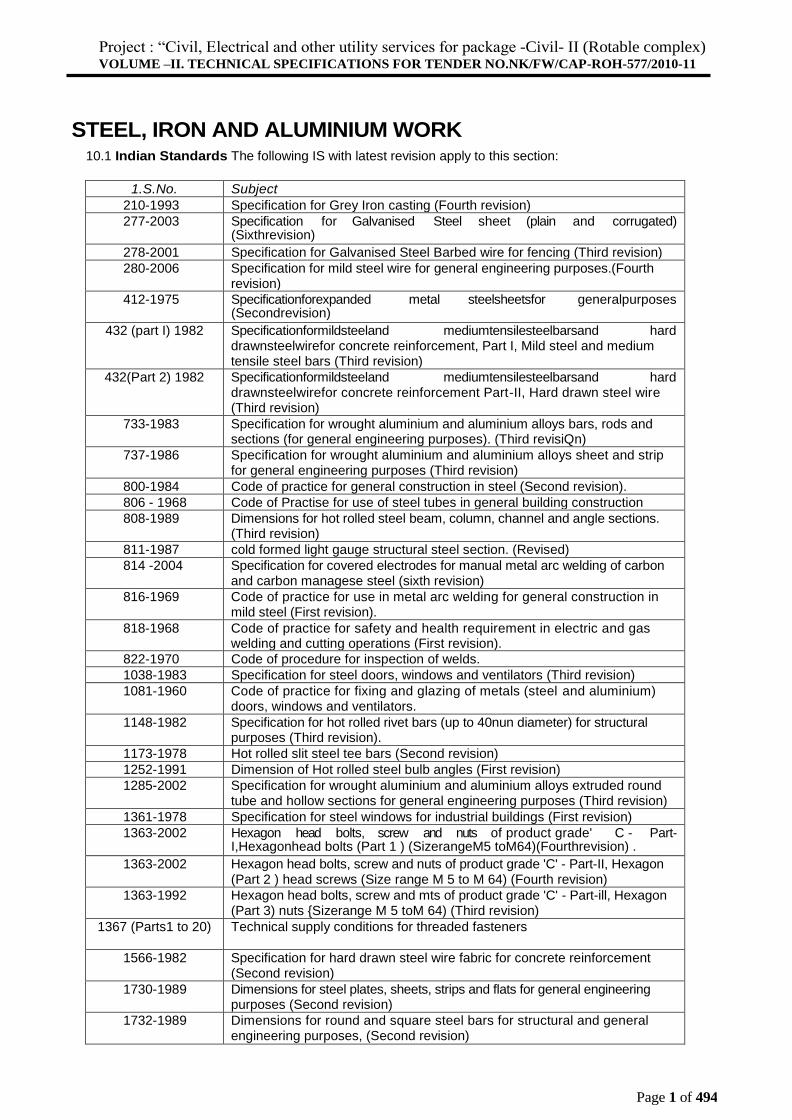
10.1 Indian Standards The following IS with latest revision apply to this section:
1.S.No. Subject
210-1993 Specification for Grey Iron casting (Fourth revision)
277-2003 Specification for Galvanised Steel sheet (plain and corrugated) (Sixthrevision)
278-2001 Specification for Galvanised Steel Barbed wire for fencing (Third revision)
280-2006 Specification for mild steel wire for general engineering purposes.(Fourth revision)
412-1975 Specificationforexpanded metal steelsheetsfor generalpurposes (Secondrevision)
432 (part I) 1982 Specificationformildsteeland mediumtensilesteelbarsand hard drawnsteelwirefor concrete reinforcement, Part I, Mild steel and medium tensile steel bars (Third revision)
432(Part 2) 1982 Specificationformildsteeland mediumtensilesteelbarsand hard drawnsteelwirefor concrete reinforcement Part-II, Hard drawn steel wire (Third revision)
733-1983 Specification for wrought aluminium and aluminium alloys bars, rods and sections (for general engineering purposes). (Third revisiQn)
737-1986 Specification for wrought aluminium and aluminium alloys sheet and strip for general engineering purposes (Third revision)
800-1984 Code of practice for general construction in steel (Second revision).
806 - 1968 Code of Practise for use of steel tubes in general building construction
808-1989 Dimensions for hot rolled steel beam, column, channel and angle sections. (Third revision)
811-1987 cold formed light gauge structural steel section. (Revised)
814 -2004 Specification for covered electrodes for manual metal arc welding of carbon and carbon managese steel (sixth revision)
816-1969 Code of practice for use in metal arc welding for general construction in mild steel (First revision).
818-1968 Code of practice for safety and health requirement in electric and gas welding and cutting operations (First revision).
822-1970 Code of procedure for inspection of welds.
1038-1983 Specification for steel doors, windows and ventilators (Third revision)
1081-1960 Code of practice for fixing and glazing of metals (steel and aluminium) doors, windows and ventilators.
1148-1982 Specification for hot rolled rivet bars (up to 40nun diameter) for structural purposes (Third revision).
1173-1978 Hot rolled slit steel tee bars (Second revision)
1252-1991 Dimension of Hot rolled steel bulb angles (First revision)
1285-2002 Specification for wrought aluminium and aluminium alloys extruded round tube and hollow sections for general engineering purposes (Third revision)
1361-1978 Specification for steel windows for industrial buildings (First revision)
1363-2002 Hexagon head bolts, screw and nuts of product grade' C - Part- I,Hexagonhead bolts (Part 1 ) (SizerangeM5 toM64)(Fourthrevision) .
1363-2002 Hexagon head bolts, screw and nuts of product grade 'C' - Part-II, Hexagon (Part 2 ) head screws (Size range M 5 to M 64) (Fourth revision)
1363-1992 Hexagon head bolts, screw and mts of product grade 'C' - Part-ill, Hexagon (Part 3) nuts {Sizerange M 5 toM 64) (Third revision)
1367 (Parts1 to 20) Technical supply conditions for threaded fasteners
1566-1982 Specification for hard drawn steel wire fabric for concrete reinforcement (Second revision)
1730-1989 Dimensions for steel plates, sheets, strips and flats for general engineering purposes (Second revision)
1732-1989 Dimensions for round and square steel bars for structural and general engineering purposes, (Second revision)
Project : “Civil, Electrical and other utility services for package -Civil- II (Rotable complex) VOLUME –II. TECHNICAL SPECIFICATIONS FOR TENDER NO.NK/FW/CAP-ROH-577/2010-11
Page 2 of 494
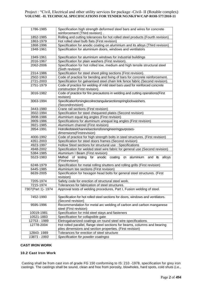
1786-1985 Specification high strength deformed steel bars and wires for concrete
reinforcement (Third revision) .
1852-1985 Rolling and cutting tolerances for hot rolled steel products (Fourth revision)
1863-1979 Hot rolled steel bulb flats (First revision)
1868-1996 Specification for anodic coating on aluminium and its alloys (Third revision)
1948-1961 Specification for aluminium doors, windows and ventilators
1949-1961 Specification for aluminium windows for industrial buildings
2016-1967 Specification for plain washers (First revision).
2062-2006 Specification for hot rolled low, medium and high tensile structural steel (Sixth revision)
2314-1986 Specification for steel sheet piling sections (First revision).
2502-1963 Code of practice for bending and fixing of bars for concrete reinforcement.
2721-2003 Specification for galvanised steel chain link fence fabric (Second revision).
2751-1979 Code of practice for welding of mild steel bars used for reinforced concrete construction (First revision).
3016-1982 Code of practice for fire precautions in welding and cutting operations(First revision)
3063-1994 Specificationforsinglecoilrectangularsectionspringlockwashers. (Secondrevision)
3443-1980 Crane rail sections (First revision)
3502-1994 Specification for steel chequered plates (Second revision)
3908-1986 Aluminium equal leg angles (First revision)
3909-1986 Specifications for aluminium unequal leg angles (First revision)
3921-1985 Aluminium channel (First revision)
3954-1991 Hotrolledsteelchannelsectionsforengineeringpurposes-dimensions(Firstrevision)
4000-1992 Code of practice for high strength bolts in steel structures. (First revision)
4351-2003 Specification for steel doors frames (Second revision)
4923-1997 Hollow Steel sections for structural use : Specifications
4948-2002 Specification for welded steel wire fabric for general use (Second revision)
5384-1985 Aluminium I Beam (First revision)
5523-1983 Method of testing for anodic coating on aluminium and its alloys (Firstrevision)
6248-1979 Specification for metal rolling shutters and rolling grills (First revision)
6445-1985 Aluminium tee sections (First revision)
6639-2005 Specification for hexagon head bolts for general steel structures. (First revision)
7205-1974 Safety code for erection of structural steel work.
7215-1974 Tolerances for fabrication of steel structures.
7307(Part 1)- 1974 Approval tests of welding procedures, Part I, Fusion welding of steel.
7452-1990 Specification for hot rolled steel sections for doors, windows and ventilators. (Second revision)
9595-1996 Recommendation for metal arc welding of carbon and carbon manganese steel (First revision)
10019-1981 Specification for mild steel stays and fasteners
10521-1883 Specification for collapsible gate
12753 - 1989 Eletrogalvanized coatings on round steel wire-specifications.
12778-2004 Hot rolled parallel, flange steel sections for beams, columns and bearing piles dimensions and section properties. (First revision)
12843- 1989 Tolerances for erection of steel structure
13871 - 1993 Specification for powder coatingss
CAST IRON WORK
10.2 Cast Iron Work
Casting shall be from cast iron of grade FG 150 conforming to IS: 210 -1978, specification for grey iron castings. The castings shall be sound, clean and free from porosity, blowholes, hard spots, cold shuts (i.e.,
Project : “Civil, Electrical and other utility services for package -Civil- II (Rotable complex) VOLUME –II. TECHNICAL SPECIFICATIONS FOR TENDER NO.NK/FW/CAP-ROH-577/2010-11
Page 3 of 494
irregularities due to casting at too low a temperature), distortion and other harmful defects. They shall be well dressed and fettled; accurately moulded in accordance with the pattern / drawing and shall be of uniform thickness except where the design necessities variation. Abrupt changes in the section: of adjoining members shall be voided as far as possible. Unless otherwise indicated edges of castings shall be rounded and integral angles finished with an angle fillet. No welding or repairs shall be carr ied out, unless otherwise indicated.
10.3 Structural Steel Work
Structural steel shall conform to
(a) Structural steel (fusion welding quality) ‘fe 410-W' conforming to IS 2062-2006, Specification for structural steel (fusion welding quality). Fe 310-0 steel may be used for general purpose such as door and window frames, window bars, grills, steel gates, handrails, tie bars etc.
10.3.1 Freedom from Defects:
All finished steel shall be well and cleanly rolled to the dimensions, sections and weights specified. The finished material shall be reasonably free from cracks, surface flaws, laminations, rough, jagged and imperfect edges, and all other harmful defects. Minor surface defects may be removed by the manufacturer by grinding provided that the thickness is not locally by more than 4 percent with a maximum of3 mm.
10.3.2 Structural steel of different sections, sizes and lengths shall be stacked separately. For each classification of steel separate areas shall be earmarked. Steel shall be marked with distinct painting marks for easy identification. All steel shall be so stored that it is always at least 15 cm above the ground level In case of long storage suitable protective measures shall be taken to prevent scaling and rusting.
10.3.3 Tolerances
Rolling and Cutting tolerances shall be as per IS 1852.
10.4 Chequered Plates
Chequered plates shall be as per requirements given in IS 3502-1994 Specification for steel chequered plates, Pattern of chequered plates shall be as directed. Plates shall be cleanly rolled and shall be reasonably free from harmful surface defects such as cracks, surface flaws, imperfect edges, etc. thickness of chequered plates specified shall be exclusive of the raised portion.
10.5 BLANK
10.6 Bolts Nuts and Washers
10.6.1 Bolts and nuts shall be conforming to the relevant requirements given in the following IS specifications and as indicated:
(a) IS1363-2002 (Parts 1 to 3) Specification for hexagon head bolts, screws and nuts Of product grade ‘C’ (Size M5 to M64)
(b) IS 1367 (Parts 1 to 20) Technical supply conditions for threaded fasteners. (c) IS 6639-2005 Specification for hexagon head bolts, for steel structures
10.6.2 The heads shall be forged. in one piece with the bolts and the nuts shall, be neatly made with the hole truly in the centre. The threads shall be full, true and deep. The heads and nuts shall be hexagonal unless square heads and nuts are specially indicated. Bolts and nuts Shall be cleanly finished and shall be sound and free from defects, which may affect their serviceability. Bolts and nuts shall be suitably protected against corrosion.
10.6.3 Washers : Plain washers shall be of steel conforming to IS 2016-1974. Specification for plain washers: Spring washers shall conform to IS 3063-1994, specification for single coil, rectangular section spring washers for bolts; nuts and screws. The washer shall be free from cracks, burns, pits to other defects. The hole shall be reasonably concentric, with the outer periphery. All sharp edges shall be removed. .
SIGNATURE OF TENDERER WITH SEAL EMPLOYER
Project : “Civil, Electrical and other utility services for package -Civil- II (Rotable complex) VOLUME –II. TECHNICAL SPECIFICATIONS FOR TENDER NO.NK/FW/CAP-ROH-577/2010-11
Page 4 of 494
10.7 Electrodes
Electrodes for metal arc welding of mild steel shall be as per IS 814-2004, Specification for covered electrodes for metal arc welding of structural steel Joints in materials above 20 mm thick and' all-important connections shall be made with low hydrogen electrodes. The mechanical properties of the weld deposit shall be such as to satisfy all the requirements such as tensile strength, elongation and impact strength of the parent, metal. 10.8 Workmanship Generally Structural steel work riveted, bolted or welded shall be carried out described in IS 800-1984, code of practice for use of structural steel in general building construction. Note :The Contractor shall prepare the shop Drawings indicating all details regarding cutlength, weld, bolts, joints, splicing, position etc., for the approval of the consultant before providing for any fabrication. All connections, bolts, welds etc., shall be neatly described in the drawing. Approval of shop Drawings by the consultant shall not relieve the Contractor from the responsibility for correctness of the dimensions and adequacy.
10.8.1 Straightening and bending:
All material shall be straight and if necessary, before being worked shall be straightened and flattened by pressure, unless required to be of curvilinear form and shall be fee from twists. Straightening of .steel by hammer blows is not permitted. All bending and cutting shall be carried out in cold condition, unless otherwise directed, in such manner as not to impair the strength of the metal.
10.9 Cutting and Machining
Member shall be. cut mechanically by saw or shear or by oxyacetylene flame. All sharp rough or broken edges and all edges of joints which are subjected to tensile or oscillating stresses shall be grounded. No electric metal arc cutting shall be allowed. All edges cut by oxyacetylene pores shall be cleaned of impurities and slag prior to assembly cutting tolerance shall be as follows:
(a) For member connected at ends +/- 1 mm.
(b) Elsewhere +/- 3 mm.
10.9.1 When compression members depend upon contact surfaces for stress transmission, then ends of columns, caps and bases together with gussets, angles 'and channels (after riveting/ welding together) shall be accurately machined so that the parts connected butt over the entire surfaces of contact. Columns at bases or at caps or at butt joints need not be machined.
10.10 Holes
All holes shall be accurately marked and drilled. Holes through more than one thickness shall preferably be drilled together after the members are assembled and tightly clamped or bolted together. In such cases, if required, these parts shall be separated after drilling and burrs removed. For thickness of materials less than 16 mm the holes may be punched 3 mm less in diameter then the required size and be reamed to the full diameter after assembly. Finished holes for rivets and black bolts shall be not more than 1.5 mm (2.0 mm for rivets and bolts or diameter more than 25 mm) in diameter larger than the diameter of rivets and bolts passing through them. All matching holes for rivets shall be so prepared that a gauge 0.8 mm diameter less than the hole can pass steely through the members assembled for riveting. Holes other than those required for close tolerance may be punched full size through material not over 12 mm thick.
10.10.1 All holes shall have their axis perpendicular to the surface bored through. Holes through two or more members shall be truly concentric. No rivet or bolt hole shall be nearer the edge of the member than distance equal to its own diameter. Holes shall not be formed by gas cutting process.
10.11 Assembly
Before assembly the contact surfaces shall be painted with a heavy coat of pure zinc chromate red oxide primer including surface preparation.
10.11.1 Laying Out:
SIGNATURE OF TENDERER WITH SEAL EMPLOYER
Project : “Civil, Electrical and other utility services for package -Civil- II (Rotable complex) VOLUME –II. TECHNICAL SPECIFICATIONS FOR TENDER NO.NK/FW/CAP-ROH-577/2010-11
Page 5 of 494
Steel structure shall be laid out on a level platform to full scale and to full size or in parts as shown on working drawings or as directed by EIC. Wooden templates 12 mm to 19 mm thick or metal sheet templates shall be made to correspond to each member and part, rivet holes shall be marked accurately on them and drilled. The templates shall be laid on the steel members and holes for riveting and bolting marked on them. The ends of the steel members shall also be marked for cutting. The base of steel columns and the positions of anchor bolts shall be carefully set out.
10.11.2 The component parts shall be assembled in such a manner that they are neither twisted nor otherwise damaged and shall be so prepared that the specified cambers, if any, are provided. All box sections shall be carefully set out.
10.11.3 Assembly shall be done by using assembly fixtures, jigs and stands, which facilitate high quality assembly with proper safety. Mis-alignment and distortion of parts after assembly shall not be allowed; only thoroughly straightened parts free from burrs, grease, rust, etc, shall be allowed for assembly.
10.11.4 Temporary connection of parts during assembly shall be done in the following way:
(a) For welded structures joining shall be done by means of tack weld, fastening devices and fixtures.
(b) For riveted and bolted structures joining shall be done by adequate number of bolts. If tack welding is permitted, in such cases the same shall be removed after the work is over.
(c) For riveted structures in which holes are to be drilled after assembly, joining shall be done by appropriate fixtures.
10.11.5 Tack welding shall be done on the sides and along the line of the weld. Tack weld dimension shall be minimum, Tack welding shall be carried out with similar electrodes as the final welding and the tacks shall completely fuse with the final weld metal.
10.11.6 In case splicing is necessary, the individual members shall be spliced first before assembly and before final welding with other members.
10.11.7 For riveted structures, members shall be well tightened by assembly bolts in every third hole maximum distance between bolts shall not exceed 500 mm. To prevent stiffening, drift pins shall be used 30 percent of the assembly bolts. After tightening, the gap between members to be jointed shall be checked by 0.2 mm thick feeler gauge which should not go inside by more than 2 mm, looseness of bolts shall be checked by tapping with a test hammer. .
10.13 Bolting
Bolt head and nuts shall be of such length as to project one clear thread beyond the nuts when fixed in position, and these shall fit in the holes without any shake. The nuts shall fit in the threaded ends Of bolts properly.
10.13.1 Round washers shall be placed under the heads and nuts' of permanent bolts. Maximum two washers for one nut and one for each bolt head shall be used. Bolt threads shall be outside the limits of joining members and unthreaded portion of bolt shall not be outside the washer.
10.13.2 Where there is risk of the nuts being removed or becoming loose due to vibration or reversal of stresses, these shall be secured from slackening by the use of lock nuts or spring washers, as directed by the EIC.
10.13.3 Bolts, nuts and washers shall be thoroughly cleaned and dipped in double linseed oil before use.
10.13.4 Quality of tightening of bolts shall be inspected by taping them with a hammer. The bolt shall not be shaken or shifted.
10.13.5 The bolts shall be tightened starting from center of the joint towards the edge.
10.14 Welding
SIGNATURE OF TENDERER WITH SEAL EMPLOYER
Project : “Civil, Electrical and other utility services for package -Civil- II (Rotable complex) VOLUME –II. TECHNICAL SPECIFICATIONS FOR TENDER NO.NK/FW/CAP-ROH-577/2010-11
Page 6 of 494
10.14.1 Welding shall be done by metal arc process unless otherwise permitted by the EIC, in writing, in accordance with IS 816-1969 Code of practice for use of metal arc welding of general construction. in mild steel, and IS 9595-1996 Recommendation of Metal .arc welding, regarding workmanship welding method, welding procedure with suitable electrodes and wire flux, combinations, quality of welds, correction of weld faults etc.
10.14.2 Preparation of members for welding:
10.14.2.1 Assembly of structural members shall be made with proper jigs and fixtures to ensure correct positioning of members (angles, axis, nodes etc)
10.14.2.2 Sharp edges, rust of cut edges, notches, irregularities and fissures to ensure due to faulty cutting shall be chipped or ground or filed over the length of the affected area deep enough to remove faults completely.
10.14.2.3 Edge preparation for welding shall be carefully and accurately made so as to facilitate a good joint.
10.14.2.4Generally, no special edge preparation shall be required for members under 8 mm thick.
10.14.2.5 Edge preparation (beveling) denotes cutting of the same so as to result in V, X, K or U seam shapes as per IS 9595.
10.14.2.6 The members to be assembled shall be clean and dry on the welding edges. Under no circumstances shall wet, greasy, rust of dirt-covered parts be assembled. Joints shall be kept free from any foreign matter, likely to get into the gaps between members to be welded.
10.14.2.7 Before assembly, the edges to be welded as well as adjacent areas extending for at least 20 mm shall be cleaned (until metallic polish is achieved)
10.14.2.8 When assembling members proper care shall be taken of welding shrinkage and distortions, as the drawing dimensions cover finished dimensions of the structures.
10.14.2.9The elements shall be got checked and approved by the EIC before assembly.
10.14.2.10.1 The permissible tolerances for assembly of members preparatory to welding shall be as per IS 9595.
After the assembly has been checked, temporary tack welding in position shall be done by electric welding, keeping in view finished dimensions of the structure.
Preheating of members to be joined to be carried put as per standards wherever necessary.
Butt Welds:
The form of joint, angle between fusion faces, gap between parts and the welding procedure shall be such that welded joint shall comply with the design requirements. The ends of butt joints in plate shall be welded so as to provide full throat thickness. In the gas-welded condition, the weld face shall be proud of the surface of the parent metal. Where a flush surface is required, the excess metal shall be dressed off. Where no dressing is to be carried out, the permissible weld profile shall be as specified in the relevant IS.
For butt weld, where these are to be welded for both sided, certain welding procedures allow this to be done without back going, but where complete penetration cannot be achieved, the back of the first run shall be gouged out to clean sound metal before welding is started on the gouged outside.
Fillet Welds:
A fillet weld as deposited shall be not less than the specified dimensions ind icated as throat thickness and/or leg thickness taking into account penetration process or partial penetration. For concave fillet welds the actual throat thickness shall be not less than 0.7 times the specified leg length. For convex fillet welds,
SIGNATURE OF TENDERER WITH SEAL EMPLOYER
Project : “Civil, Electrical and other utility services for package -Civil- II (Rotable complex) VOLUME –II. TECHNICAL SPECIFICATIONS FOR TENDER NO.NK/FW/CAP-ROH-577/2010-11
Page 7 of 494
the actual throat thickness shall be not less than 0.9 times the specified leg length.
Preparation of joint Faces:
If preparation or cutting of material is necessary, this shall be done by shearing, chipping, grinding, machining, thermal cutting. When shearing is used the effect of work hardening shall be taken care of to ensure that there is no cracking of the edges. Removal of 1 mm to 2 mm from a cut face normally eliminates the layer of hardness.
Fusion Faces:
Fusion faces and adjustment surfaces shall be free from cracks, notches or other irregularities which might be the cause of defects or would interfere with the deposition of the weld. They shall also be free from heavy scale, moisture, oil, paint and any other substances which might affect the quality of weld or impede the progress of welding.
Assembly for Welding:
Jigs and manipulators should be used, where practicable, so that the welding can be carried out in the most suitable position. Jigs shall maintain the alignment with the minimum restraint so as to reduce the possibility of lock in stresses.
Alignment of Butt Joint:
The root edges or root faces of butt joints shall not be out of alignment by more than 25 percent of the thickness of the thinner material for material up to 12 mm thick or by more than 3 mm for thicker material For certain applications closer tolerances may be necessary for proper alignment.
Fit up of parts jointed by fillet welds:
The edges and surfaces to be jointed by fillet welds shall be in close contact as possible since any gap increases the risk of cracking but in no Case should be gap exceed 3 mm.
10.14.10 Tack Welds:
Tack welds shall be not less than the throat thickness or leg lengths of the root run to be used in the joint. The length of the tack weld shall not be less than four times the thickness of the thicker part or 50 mm whichever is smaller. If smaller tack welds are desired, these shall be so indicated.
Where a tack weld is incorporated in a welded joint, the shape of the tack shall be suitable for incorporation in the finished weld and it shall be free from cracks and other deposition faults.
10.14.11 Protection from Weather.
Surface to be welded shall be dry. When rain or snow is falling or during periods of high wind, necessary precautions shall be taken for outdoor welding. Warming shall be carried out at all ambient temperatures below 10°C.
10.14.12 Inter-Run Cleaning:
Each run of weld bead and each layer of weld shall be thoroughly cleaned of slag, spatters, etc., before depositing subsequent bead or weld with particular' reference to thorough cleaning of toes of the welds. Visible defects' such as cracks, cavities and other deposition faults, if any, shall be removed to sound metal before depositing subsequent run or layer of weld.
10.14.13 Welding Procedure:
10.14.13.1 Welding shall be carried out only by fully trained and experienced welders as tested and approved by the EIC.
10.14.13.2 Qualification tests for welders as well as tests for approval of electrodes will .be carried out as per IS 823. The nature of test for performance qualification for welders shall commensurate with the
SIGNATURE OF TENDERER WITH SEAL EMPLOYER
Project : “Civil, Electrical and other utility services for package -Civil- II (Rotable complex) VOLUME –II. TECHNICAL SPECIFICATIONS FOR TENDER NO.NK/FW/CAP-ROH-577/2010-11
Page 8 of 494
quality of welding required on this work as judged by the EIC.
10.14.13.3 The steel structures shall be automatically, semi-automatically or manually welded.
10.14.13.4 Welding shall be done only after the checks shown under clause 10.15 have been carried out.
10.14.13.5 Welding procedures and tests for welders shall be conducted as per IS 9595 and approved by the EIC
10.14.13.6.1 The welder shall mark with his identification mark on each element welded by him.
10.14.13.7 When welding is carried out in open air steps shall be taken to protect the places of welding against wind or rain. The electrodes wire and parts being weld on shall be dry.
10.14.13.8 Before beginning the welding operation each joint shall be checked to assure that the parts
to be welded are clean and root gaps provided as per IS 9595
10.14.13.9 For continuing the welding of seams discontinued due to some reasons the end of the discontinued seam shall be melted in order to obtain a good continuity. Before resuming the welding operation the groove as well as the adjacent parts shall be well cleaned for a length of approximately 50 mm.
10.14.13.10 For single butt welds (in V,1/2V or U) and double butt welds ( in K. double U, etc) the rewelding .of the root butt is mandatory but only after the metal deposition on the root has been cleaned by back gouging or chipping.
10.14.13.11 The welding seams shall be left to cool slowly. The contractor shall not be allowed to cool the welds quickly by any method.
10.14.13.12 For multi layer welding before welding the following layer, the formerly -welded layer shall be cleaned metal bright by light chipping and wire brushing. Backing strips shall not be allowed. 10.14.13.13 The order and method of welding shall be so that :
(a) No unacceptable deformation appeared in the welded parts
(b) Two. margin is provided to compensate for contraction due to welding in order to avoid any a high permanent stresses.
10.14.13.14 The defects in welds shall be rectified to IS: 9595 and as per instruction of EIC.
All weld shall be inspected by Dye Penetration before painting, any weld found to be defective shall be cut by using either chipping hammer or any other means in such a manner that the adjacent material is not damaged.
10.14.14 Approval and Testing of welders:
The contractors shall satisfy the EIC that the welder is suitable for the work up on which they will be employed.
10.14.15 Weld instruction:
The weld seams shall satisfy the following:
a. shall correspond to design, shapes and dimensions
b. Shall not have any defects such as cracks, incomplete penetration and fusion under cuts, rough surfaces, burns, blow holes, and porosity etc beyond permissible
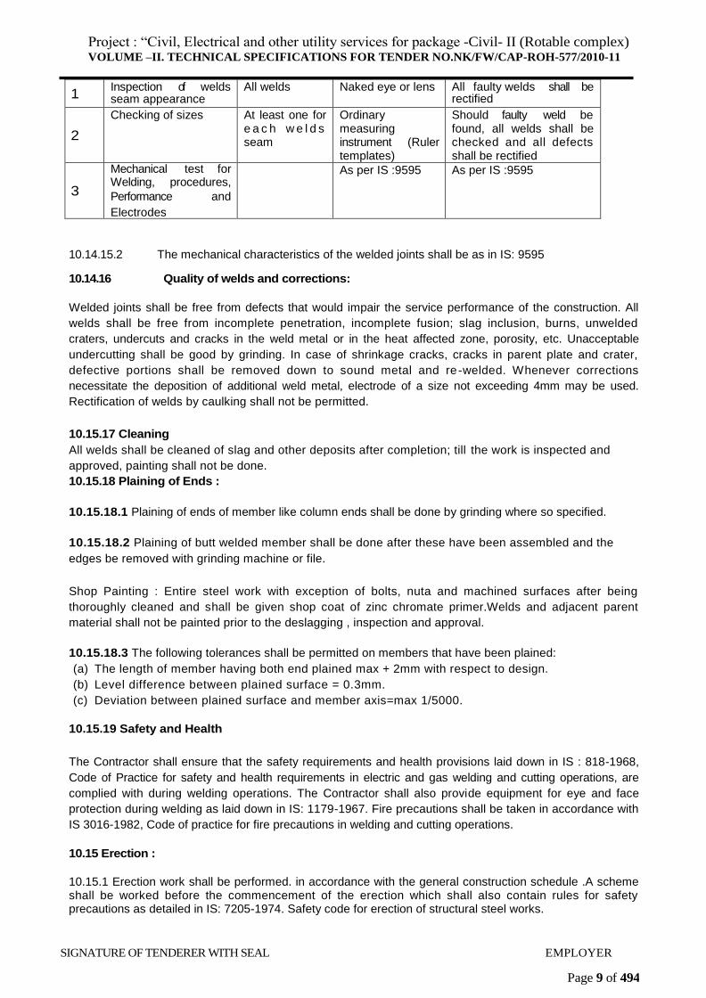
10.14.15.1 During the welding operation and approval-of finished elements inspection ant test shall be made as shown in table 1 below
SL No
Inspection of test Coverage Procedure Evaluation and remedy of defects
SIGNATURE OF TENDERER WITH SEAL EMPLOYER
Project : “Civil, Electrical and other utility services for package -Civil- II (Rotable complex) VOLUME –II. TECHNICAL SPECIFICATIONS FOR TENDER NO.NK/FW/CAP-ROH-577/2010-11
Page 9 of 494
1 Inspection of welds seam appearance
All welds Naked eye or lens All faulty welds shall be rectified
2
Checking of sizes At least one for e a c h w e l d s seam
Ordinary measuring instrument (Ruler templates)
Should faulty weld be found, all welds shall be checked and all defects shall be rectified
3
Mechanical test for Welding, procedures,
Performance and
Electrodes
As per IS :9595 As per IS :9595
10.14.15.2 The mechanical characteristics of the welded joints shall be as in IS: 9595
10.14.16 Quality of welds and corrections:
Welded joints shall be free from defects that would impair the service performance of the construction. All
welds shall be free from incomplete penetration, incomplete fusion; slag inclusion, burns, unwelded
craters, undercuts and cracks in the weld metal or in the heat affected zone, porosity, etc. Unacceptable
undercutting shall be good by grinding. In case of shrinkage cracks, cracks in parent plate and crater,
defective portions shall be removed down to sound metal and re-welded. Whenever corrections
necessitate the deposition of additional weld metal, electrode of a size not exceeding 4mm may be used.
Rectification of welds by caulking shall not be permitted.
10.15.17 Cleaning
All welds shall be cleaned of slag and other deposits after completion; till the work is inspected and
approved, painting shall not be done.
10.15.18 Plaining of Ends :
10.15.18.1 Plaining of ends of member like column ends shall be done by grinding where so specified.
10.15.18.2 Plaining of butt welded member shall be done after these have been assembled and the
edges be removed with grinding machine or file.
Shop Painting : Entire steel work with exception of bolts, nuta and machined surfaces after being
thoroughly cleaned and shall be given shop coat of zinc chromate primer.Welds and adjacent parent
material shall not be painted prior to the deslagging , inspection and approval.
10.15.18.3 The following tolerances shall be permitted on members that have been plained:
(a) The length of member having both end plained max + 2mm with respect to design.
(b) Level difference between plained surface = 0.3mm.
(c) Deviation between plained surface and member axis=max 1/5000.
10.15.19 Safety and Health
The Contractor shall ensure that the safety requirements and health provisions laid down in IS : 818-1968,
Code of Practice for safety and health requirements in electric and gas welding and cutting operations, are
complied with during welding operations. The Contractor shall also provide equipment for eye and face
protection during welding as laid down in IS: 1179-1967. Fire precautions shall be taken in accordance with
IS 3016-1982, Code of practice for fire precautions in welding and cutting operations.
10.15 Erection :
10.15.1 Erection work shall be performed. in accordance with the general construction schedule .A scheme shall be worked before the commencement of the erection which shall also contain rules for safety precautions as detailed in IS: 7205-1974. Safety code for erection of structural steel works.
SIGNATURE OF TENDERER WITH SEAL EMPLOYER
Project : “Civil, Electrical and other utility services for package -Civil- II (Rotable complex) VOLUME –II. TECHNICAL SPECIFICATIONS FOR TENDER NO.NK/FW/CAP-ROH-577/2010-11
Page 10 of 494
10.15.2 Anchor bolts for fastening of steel structures shall be set in designed positions and grouted along with foundations. Alternatively anchor bolts should be provided in the .concrete foundation with bolt boxes and anchor channels for the purpose of flexibility and grouted after final alignment and levelling Column.
10.15.3 The gaps between the bearing surface of foundation and bottom of the structure to be erected shall be filled properly by cement grouting. Grouting shall be done after the verification and proper positioning of the' structures but before encasing the structures with concrete if specified.
10.15.4 Damaged structural members shall be examined and rectified or replaced as directed.
10.15.5 The erected parts of the structures shall be stable during all the stages of erection; and structural elements to be erected shall be stable and strong to bear erection loads.
10.15.6 Working on the already erected structures is permitted only after they are finally fixed. Erection of structures of each tier for high structures shall be executed only after fastening of lower tier by the permanent or temporary fastening devices as per schedule of execution of work and certified for safety.
10.15.7 The joint and mating surface including the mating planes, strips and filler or spacers shall be cleaned of dust, rut and water.
10.15.8 Erected structural members shall be firmly fastened by bolts and drifts, permanent or provisional tacking, crossing bars and so on before the erection crane hook is removed.
10.15.9 The trusses shall be lifted only at nodes. The trusses above 12 m span shall not be singed at the apex, as it will develop compression stresses in the bottom tie member. It shall be lifted by slinging at two mid points of rafters, which' shall be temporarily braced by a wooden member of suitable section. After the trusses are placed in position purlins and wind bracings shall be fixed as soon as possible. The end of truss which faces the prevailing winds shall be fixed with holding down bolts and the other end kept free to move. In case of small truss of span say up to 12 mm the free end of the truss shall be laid on steel plate as per design and the holes for holding down bolts shall be made in the form of oblong slot as to permit the free movement of the truss end. For large spans, the free end of the truss shall be provided with suitable rocker and roller bearing where indicated.
10.15.10 Erection Joints:
While erecting, holes to be riveted shall be fitted with temporary bolts and drifts of diameter equal to those of the holes. It is necessary to install drifts for accurate matching of holes. Number of bolts and drifts shall not be. less than 40 Percent of total number of holes. Forces applied to drifts shall be same as approved for rivets. Number of drifts shall be 10 percent of number of holes.
10.15.11 The number, size and length of tack welds in erection forces shall be as indicated. For the erection joints which do not bear the erection forces the length of tack welds shall be minimum 10 percent of tube designed weld length of the joint.
10.15.12.1 Welding, riveting and final fastening of permanent bolts shall be done only after the inspection of the structural elements for their positions. Head bolts and nuts shall perfectly be in touch with the surfaces of structures and washers.
10.15.13 Tolerance Allowed in Erection;
10.15.13.1 Building without crane:
The maximum tolerance for-line and level of steel structure shall be ±3 mm on any part of the structure. The structure shall not be out of plumb more than 5 mm on each 10 meter section in height and not more than 8 mm per 30 metre section. These tolerance shall apply to all parts of structure unless otherwise specified.
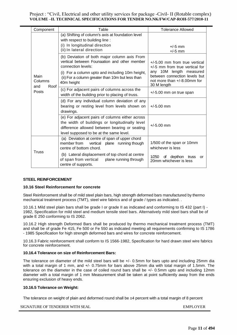
10.15.13.2.1 Tolerance allowed in erection of steel structure containing cranes shall be as per following
table:
SIGNATURE OF TENDERER WITH SEAL EMPLOYER
Project : “Civil, Electrical and other utility services for package -Civil- II (Rotable complex) VOLUME –II. TECHNICAL SPECIFICATIONS FOR TENDER NO.NK/FW/CAP-ROH-577/2010-11
Page 11 of 494
Component Table Tolerance Allowed
Main
Columns
and Roof
Posts
(a) Shifting of column's axis at foundation level
with respect to building line :
(i) In longitudinal direction (ii) In lateral direction
+/-5 mm +/-5 mm
(b) Deviation of both major column axis From
vertical between Founaation and other member
connection levels:
(i) For a column upto and including 10m height,
(ii) For a column greater than 10m but less than
40m height
+/-5.00 mm from true vertical +/-5 mm from true vertical for any 10M length measured between connection levels but not more than +/-8.00mm for 30 M length
(c) For adjacent pairs of columns across the
width of the building prior to placing of truss. +/-5.00 mm on true span
(d) For any individual column deviation of any
bearing or resting level from levels shown on
drawings.
+/-5.00 mm
(e) For adjacent pairs of columns either across
the width of buildings or longitudinally level
difference allowed between bearing or seating
level supposed to be at the same level.
+/-5.00 mm
Truss
(a) Deviation at centre of span of upper chord
member from vertical plane running though
centre of bottom chord.
(b) Lateral displacement of top chord at centre
of span from vertical plane running through
centre of supports.
1/500 of the span or 10mm
whichever is less
1/250 of depthon truss or 20mm whichever is less
STEEL REINFORCEMENT
10.16 Steel Reinforcement for concrete
Steel Reinforcement shall be of mild steel plain bars, high strength deformed bars manufactured by thermo mechanical treatment process (TMT), steel wire fabrics and of grade / types as indicated. .
10.16.1 Mild steel plain bars shall be grade I or grade II as indicated and conforming to IS 432 (part I) - 1982, Specification for mild steel and medium tensile steel bars. Alternatively mild steel bars shall be of grade E 250 conforming to IS 2062.
10.16.2 High strength Deformed Bars shall be produced by thermo mechanical treatment process (TMT) and shall be of grade Fe 415, Fe 500 or Fe 550 as indicated meeting all requirements confirming to IS 1786 - 1985 Specification for high strength deformed bars and wires for concrete reinforcement.
10.16.3 Fabric reinforcement shall conform to IS 1566-1982, Specification for hard drawn steel wire fabrics for concrete reinforcement.
10.16.4 Tolerance on size of Reinforcement Bars:
The tolerance on diameter of the mild steel bars will be +/- 0.5mm for bars upto and including 25mm dia with a total margin of 1 mm, and +/- 0.75mm for bars above 25mm dia with total margin of 1.5mm. The tolerance on the diameter in the case of coiled round bars shall be +/- 0.5mm upto and including 12mm diameter with a total margin of 1 mm Measurement shall be taken at point sufficiently away from the ends ensuring exclusion of heavy ends.
10.16.5 Tolerance on Weight:
The tolerance on weight of plain and deformed round shall be ±4 percent with a total margin of 8 percent
SIGNATURE OF TENDERER WITH SEAL EMPLOYER
Project : “Civil, Electrical and other utility services for package -Civil- II (Rotable complex) VOLUME –II. TECHNICAL SPECIFICATIONS FOR TENDER NO.NK/FW/CAP-ROH-577/2010-11
Page 12 of 494
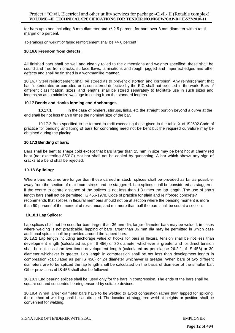
for bars upto and including 8 mm diameter and +/-2.5 percent for bars over 8 mm diameter with a total margin of 5 percent.
Tolerances on weight of fabric reinforcement shall be +/- 6 percent
10.16.6 Freedom from defects:
All finished bars shall be well and cleanly rolled to the dimensions and weights specified: these shall be sound and free from cracks, surface flaws, laminations and rough, jagged and imperfect edges and other defects and shall be finished in a workmanlike manner.
10.16.7 Steel reinforcement shall be stored as to prevent distortion and corrosion. Any reinforcement that has "deteriorated or corroded or is considered defective by the EIC shall not be used in the work. Bars of different classification, sizes, and lengths shall be stored separately to facilitate use in such sizes and lengths so as to minimize wastage in cutting from the standard lengths
10.17 Bends and Hooks forming end Anchorages
10.17.1 In the case of binders, stirrups, links, etc the straight portion beyond a curve at the
end shall be not less than 8 times the nominal size of the bar.
10.17.2 Bars specified to be formed to radii exceeding those given in the table X of IS2502.Code of practice for bending and fixing of bars for concreting need not be bent but the required curvature may be obtained during the placing.
10.17.3 Bending of bars:
Bars shall be bent to shape cold except that bars larger than 25 mm in size may be bent hot at cherry red heat (not exceeding 850°C) Hot bar shall not be cooled by quenching. A bar which shows any sign of cracks at a bend shall be rejected.
10.18 Splicing:
Where bars required are longer than those carried in stock, splices shall be provided as far as possible,
away from the section of maximum stress and be staggered. Lap splices shall be considered as staggered
if the centre to centre distance of the splices is not less than 1.3 times the lap length .The use of short
length bars shall not be permitted. IS 456-1978, Code of practice for plain and reinforced concrete?
recommends that splices in flexural members should not be at section where the bending moment is more
than 50 percent of the moment of resistance; and not more than half the bars shall be sed at a section.
10.18.1 Lap Splices:
Lap splices shall not be used for bars larger than 36 mm dia, larger diameter bars may be welded, in cases where welding is not practicable, lapping of bars larger than 36 mm dia may be permitted in which case additional spirals shall be provided around the lapped bars. 10.18.2 Lap length including anchorage value of hooks for bars in flexural tension shall be not less than
development length (calculated as per IS 456) or 30 diameter whichever is greater and for direct tension
shall be not less than two times development length (calculated as per clause 26.2.1 of IS 456) or 30
diameter whichever is greater. Lap length in compression shall be not less than development length in
compression (calculated as per IS 456) or 24 diameter whichever is greater. When bars of two different
diameters are to be spliced the lap length shall be calculated on the basis of diameter of the smaller bar.
Other provisions of IS 456 shall also be followed.
10.18.3 End bearing splices shall be, used only for the bars in compression. The ends of the bars shall be square cut and concentric bearing ensured by suitable devices.
10.18.4 When larger diameter bars have to be welded to avoid congestion rather than lapped for splicing, the method of welding shall be as directed. The location of staggered weld at heights or position shall be convenient for welding.
SIGNATURE OF TENDERER WITH SEAL EMPLOYER
Project : “Civil, Electrical and other utility services for package -Civil- II (Rotable complex) VOLUME –II. TECHNICAL SPECIFICATIONS FOR TENDER NO.NK/FW/CAP-ROH-577/2010-11
Page 13 of 494
10.18.5 Spiral Reinforcement:
Spirals shall be provided with one and a half extra turns at both top and bottom. Where necessary to splice the spiral it shall be done by a lap of one and a half turns or by shop welding.
10.18.6 Placing and fixing of bars
Reinforcement shall be placed in position as per detailed design drawing and shall be secured at that position. In case of delay' occurring between fixing of reinforcement and concreting, the position of the reinforcement shall be checked prior to concreting. Bars crossing each other shall be secured by binding wire (annealed) of size not less than 0.9 mm and conforming to IS 280-1978. Specification for mild steel wire, in such a manner that they will not slip over each other at the time of fixing and concreting. Every compression bar shall be tied at least in two perpendicular directions.
10.19.1 Cover Blocks:
Cover blocks generally of PVC or cement mortar. shall be used to ensure the required cover for the reinforcement. 'The mortar or concrete used for the cover blocks or rings shall, be not leaner than the mortar or concrete in which they would be embedded.
10.19.2 Spacers:
Where multiple rows of reinforcement are provided distances between successive rows shall be properly maintained while concreting by providing suitable spacer bars.
10.19.3 Placing Reinforcement:
All mill scale, loose or scaly rust, oil and grease or any coating that will destroy the bond shall be thoroughly cleaned off the steel reinforcement with a stiff wire brush or approved means before it is placed in forms. Steel reinforcement when placed in the forms. shall be properly braced, supported, or otherwise held firmly in position so that placing and ramming/vibrating of concrete does not displace it. -'
10.19.4 It shall be ensured that all reinforcement can be properly placed. Congestion of steel shall be avoided at points where members intersect.
10.19.5 Tolerance in Placing of reinforcement:
Unless otherwise indicated, reinforcement shall be placed within following tolerance.
a) For effective depth 200 mm or less = +/ -10mm
b) For effective depth more than 200mm=+/ -15mm
The cover shall in no case be reduced by more than 1/3 of specified cover or 5 mm whichever is less.
10.20 Steel Wire Fabric Reinforcement
Hard drawn steel fabric shall conform to IS 1566-1982 specification for bard drawn steel wire fabric for concrete reinforcement, MESH size, weight, size of wire for square and oblong welded wire fabric shall be indicated. The fabric shall be formed by spacing the main and the cross wire, which shall be fixed at the point of inter-section by electric welding.
"Since fabric is supplied in long rolls it is rarely necessary to have a joint of the main wires. In structural slab laps in regions, of maximum stress shall be avoided. When splicing of welded wire fabric is to be carried out, lap splices of wires shall be made so that overlap measured between the extreme cross wires shall be not less than the spacing of Cross wires plus 10 cm. For edge laps a lap of 5 cm shall be provided.
10.21 Welding of Reinforcement
Welding of bars where indicated or agreed to by the EIC, in writing, in lieu of lapping shall be done in accordance with IS 2751-1979 code of practice for welding of concrete construction. Welding in general shall be done as described for structural steel work.
SIGNATURE OF TENDERER WITH SEAL EMPLOYER
Project : “Civil, Electrical and other utility services for package -Civil- II (Rotable complex) VOLUME –II. TECHNICAL SPECIFICATIONS FOR TENDER NO.NK/FW/CAP-ROH-577/2010-11
Page 14 of 494
10.21.1 Bars up to and including 20 mm dia shall be lap welded and those larger than 20 mm dia shall be butt- welded. In case of lap welds, the length of lap shall be five times the dia or 100 mm whichever is greater. The throat thickness shall not be less than 3 mm for bars up to 16 mm dia and 5 mm for bars over 16 mm dia and up to 20 mm dia. Butt Welding
Where it is not possible to rotate bars for welding in flat position the axis of the bars shall be horizontal and the respective axis of the welds shall be vertical .The edge preparation for inclined bars shall be such that welding is done only on sides. All the bars to the butt-welded shall be aligned and set up in position with their axis in one straight line. This may be done in a jig or by means of a clamp or by using guides. Rotation of the bars shall be avoided, until they are adequately welded.
Lap Welding
Edge preparation is not necessary for lap welds.
Finish:
The profile of the welds shall be uniform, slightly convex and free from overlap at the toes of the welds. The weld face shall be uniform in appearance throughout its length. The welded joint shall be free from undercut. The joints in the weld run shall be as smooth as practicable and shall show no pronounced hump or crater in the weld surface. The surface of the weld shall be free from porosity, c
avities and trapped slag.
Steel Rolling Shutters
Steel rolling shutters shall be of approved make and shall conform to the requirements of IS 6248 - 1979specification for metal rolling shutters and rolling grills. The size of the rolling shutters (denoted by clear
width and clear height) shall be as indicated. The position of fixing of the rolling shutter shall be as indicated viz inside or outside or within jambs; with projecting or embedded guide channels and above or below the soffits.
Rolling shutters shall be gear operated type with bevel gear box and crank handle.
Curtain
The curtain shall be built up of inter-locking lath sections formed from cold rolled steel strips 1.20 mm thick for all shutters unless otherwise specified. The lath section shall be rolled so as to have interlocking curls at both edges and a deep corrugation at the center with a bridge depth of not less than 12 mm. Each lath section shall be continuous single piece without any welded joint. When interlocked, the lath sections shall have a distance of 75 mm between rolling centers, unless otherwise specified. Each alternate lath section shell be fitted with malleable cast iron or mild steel clips securely riveted at either ends.
Lock Plate:
A fabricated lock plate of riveted construction made of mild steel sheet of not less than 3.15 mm thickness, reinforced with mild steel angle section of not less than 35x35x5 mm size at the bottom, shall be interlocked with bottom most lath Section of curtain so as to provide contact against the sill, when closed. The lock plate shall be fitted with sliding bolts, with arrangements for locking with pad locks and also pulling handles of mild steel, one handle for width upto 2.5 m and two handles for widths of above 2.5 m pulling handle shall be fixed on both the interior and exterior side of the lock plate.
10.22.4 Guide Channels:
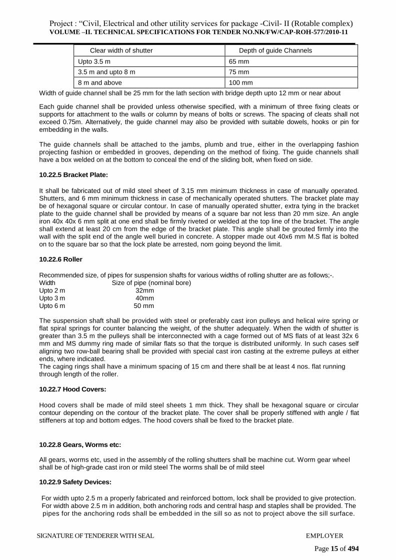
The guide channels shall be of mild steel deep channel section and of rolled, pressed or buil t up construction. Thickness of sheet shall not be less than 3.15 mm.The curtain shall project into the guide channel at least 40 mm upto 3,5 mm width and 60 mm for greater widths. There shall be a clearance of 10 mm minimum between the guide waIl and end clips of the curtain. Minimum depth of the guide channels shall be as under:
Project : “Civil, Electrical and other utility services for package -Civil- II (Rotable complex) VOLUME –II. TECHNICAL SPECIFICATIONS FOR TENDER NO.NK/FW/CAP-ROH-577/2010-11
Page 15 of 494
Clear width of shutter Depth of guide Channels
Upto 3.5 m 65 mm
3.5 m and upto 8 m 75 mm
8 m and above 100 mm
Width of guide channel shall be 25 mm for the lath section with bridge depth upto 12 mm or near about
Each guide channel shall be provided unless otherwise specified, with a minimum of three fixing cleats or supports for attachment to the walls or column by means of bolts or screws. The spacing of cleats shall not exceed 0.75m. Alternatively, the guide channel may also be provided with suitable dowels, hooks or pin for embedding in the walls.
The guide channels shall be attached to the jambs, plumb and true, either in the overlapping fashion projecting fashion or embedded in grooves, depending on the method of fixing. The guide channels shall have a box welded on at the bottom to conceal the end of the sliding bolt, when fixed on side.
10.22.5 Bracket Plate:
It shall be fabricated out of mild steel sheet of 3.15 mm minimum thickness in case of manually operated. Shutters, and 6 mm minimum thickness in case of mechanically operated shutters. The bracket plate may be of hexagonal square or circular contour. In case of manually operated shutter, extra tying in the bracket plate to the guide channel shall be provided by means of a square bar not less than 20 mm size. An angle iron 40x 40x 6 mm split at one end shall be firmly riveted or welded at the top line of the bracket. The angle shall extend at least 20 cm from the edge of the bracket plate. This angle shall be grouted firmly into the wall with the split end of the angle well buried in concrete. A stopper made out 40x6 mm M.S flat is bolted on to the square bar so that the lock plate be arrested, nom going beyond the limit.
10.22.6 Roller
Recommended size, of pipes for suspension shafts for various widths of rolling shutter are as follows;-. Width Size of pipe (nominal bore) Upto 2 m 32mm Upto 3 m 40mm Upto 6 m 50 mm
The suspension shaft shall be provided with steel or preferably cast iron pulleys and helical wire spring or flat spiral springs for counter balancing the weight, of the shutter adequately. When the width of shutter is greater than 3.5 m the pulleys shall be interconnected with a cage formed out of MS flats of at least 32x 6 mm and MS dummy ring made of similar flats so that the torque is distributed uniformly. In such cases self aligning two row-ball bearing shall be provided with special cast iron casting at the extreme pulleys at either ends, where indicated. The caging rings shall have a minimum spacing of 15 cm and there shall be at least 4 nos. flat running through length of the roller.
10.22.7 Hood Covers:
Hood covers shall be made of mild steel sheets 1 mm thick. They shall be hexagonal square or circular contour depending on the contour of the bracket plate. The cover shall be properly stiffened with angle / flat stiffeners at top and bottom edges. The hood covers shall be fixed to the bracket plate.
10.22.8 Gears, Worms etc:
All gears, worms etc, used in the assembly of the rolling shutters shall be machine cut. Worm gear wheel shall be of high-grade cast iron or mild steel The worms shall be of mild steel
10.22.9 Safety Devices:
For width upto 2.5 m a properly fabricated and reinforced bottom, lock shall be provided to give protection. For width above 2.5 m in addition, both anchoring rods and central hasp and staples shall be provided. The pipes for the anchoring rods shall be embedded in the sill so as not to project above the sill surface.
SIGNATURE OF TENDERER WITH SEAL EMPLOYER
Project : “Civil, Electrical and other utility services for package -Civil- II (Rotable complex) VOLUME –II. TECHNICAL SPECIFICATIONS FOR TENDER NO.NK/FW/CAP-ROH-577/2010-11
Page 16 of 494
Anchoring rods shall be provided at the .rate of one per extra 2.5 m width or a part there of above a clear width of 2.5 m. The hasp shall be grouted on the ground so as to be level with the sill.
10.22.10 Wicket Doors:
Where indicated, wicket door of 600x1200 mm size for ordinary use and 900x 1800 mm size for large installation shall be provided in the rolling shutters. The wicket door shall be robust construction and shall be fitted with a good lever lock operated by key, lockable both from inside and outside. The wicket doors shall be erected in such a way as not to foul with the main rolling shutters when opening or closing. The wicket door shall be swung clear of the opening before the rolling shutter is raised or lowered.
10.22.11 Safety Lever Locks:
Where indicated one pair of safety lever locks may be fitted on either ends of the bottom lock plate.
10.23 Rolling Grill
In situation where certain amount of ventilation combined with safety is required, for example transformer room, substation etc, the rolling shutter may have a small rolling grill portion either at top or at bottom or at both places as indicated. Rolling grill shall be built of cold rolled steel sheet links of 0.9 mm thickness assembled on tubes or rods. Grill may also be manufactured out of 8 mm dia MS round bars. Design of grill shall be as indicated.
10.24 Blank
10.25 Steel windows
Steel doors, windows and ventilators shall comply with IS 1038-1983, Specification or steel doors, windows
and ventilators; except with regard to sizes, which shall be as indicated; and shall be of approved make.
Rolled steel sections for fabrication shall conform to IS 7452-1990.
10.25.1 Fabrication:
Both fixed and opening frames shall be constructed of sections mixed at corners. The comers of frames
shall be welded to form a solid fused welded joint. All frames shall be square and flat. The process of
welding adopted may be flash butt welding or any other suitable method which complies with the
requirements listed in the IS. Subdividing bars of the units shall be tenoned and riveted to the frames.
Casements shall be fitted to their frames so as to provide continuous contact to weathering on the inside
and outside and shall be secured in closed position by the fittings which shall have been properly adjusted.
Windows and doors may have holes in the web of bars other than those required during manufacture and
fixing. Fixing lugs shall have standard slot of 8mm wide for MS screw of 6 mm. dia and 12 mm long with
square nuts.
10.25.2 For fixing steel hinges, slots shall be cut in the fixed frame and the hinges inserted inside and
welded to the fame. The hinges shall be projecting type and not less than 65mm and not more than 75mm
wide. The hinge pin shall be of electro-galvanised steel of suitable thickness. Where indicated, friction
hinges shall be provided for side hung windows.
10.25.3 Side hung shutters
The handles for side hung shuters shall be of steel or of hot pressed brass, where indicated and shall be
mounted on a steel handle plate. Thickness of handle shall not be less than 3 mm for mild steel and brass.
The handle shall have a two point nose which shall engage with a steel/brass striking plate on the fixed
frame in a slightly. open position as well as in a fast position. The boss of the handle shall incorporate a
friction device to prevent the handle from dropping under its own weight and the assembly shall be so
designed that the rotation of the handle may not cause it to unscrew from the pin. The strike plate shall be
so designed and fixed in such a position in relation that with the latter bearing against its stop, there shall
be adequate tight fit between the casement and the outer frames.
SIGNATURE OF TENDERER WITH SEAL EMPLOYER
Project : “Civil, Electrical and other utility services for package -Civil- II (Rotable complex) VOLUME –II. TECHNICAL SPECIFICATIONS FOR TENDER NO.NK/FW/CAP-ROH-577/2010-11
Page 17 of 494
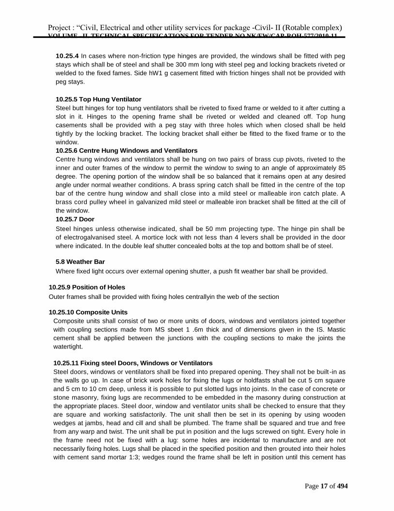
10.25.4 In cases where non-friction type hinges are provided, the windows shall be fitted with peg
stays which shall be of steel and shall be 300 mm long with steel peg and locking brackets riveted or
welded to the fixed fames. Side hW1 g casement fitted with friction hinges shall not be provided with
peg stays.
10.25.5 Top Hung Ventilator
Steel butt hinges for top hung ventilators shall be riveted to fixed frame or welded to it after cutting a
slot in it. Hinges to the opening frame shall be riveted or welded and cleaned off. Top hung
casements shall be provided with a peg stay with three holes which when closed shall be held
tightly by the locking bracket. The locking bracket shall either be fitted to the fixed frame or to the
window.
10.25.6 Centre Hung Windows and Ventilators
Centre hung windows and ventilators shall be hung on two pairs of brass cup pivots, riveted to the
inner and outer frames of the window to permit the window to swing to an angle of approximately 85
degree. The opening portion of the window shall be so balanced that it remains open at any desired
angle under normal weather conditions. A brass spring catch shall be fitted in the centre of the top
bar of the centre hung window and shall close into a mild steel or malleable iron catch plate. A
brass cord pulley wheel in galvanized mild steel or malleable iron bracket shall be fitted at the cill of
the window.
10.25.7 Door
Steel hinges unless otherwise indicated, shall be 50 mm projecting type. The hinge pin shall be
of electrogalvanised steel. A mortice lock with not less than 4 levers shall be provided in the door
where indicated. In the double leaf shutter concealed bolts at the top and bottom shall be of steel.
5.8 Weather Bar
Where fixed light occurs over external opening shutter, a push fit weather bar shall be provided.
10.25.9 Position of Holes
Outer frames shall be provided with fixing holes centrallyin the web of the section
10.25.10 Composite Units
Composite units shall consist of two or more units of doors, windows and ventilators jointed together
with coupling sections made from MS sbeet 1 .6m thick and of dimensions given in the IS. Mastic
cement shall be applied between the junctions with the coupling sections to make the joints the
watertight.
10.25.11 Fixing steel Doors, Windows or Ventilators
Steel doors, windows or ventilators shall be fixed into prepared opening. They shall not be built -in as
the walls go up. In case of brick work holes for fixing the lugs or holdfasts shall be cut 5 cm square
and 5 cm to 10 cm deep, unless it is possible to put slotted lugs into joints. In the case of concrete or
stone masonry, fixing lugs are recommended to be embedded in the masonry during construction at
the appropriate places. Steel door, window and ventilator units shall be checked to ensure that they
are square and working satisfactorily. The unit shall then be set in its opening by using wooden
wedges at jambs, head and cill and shall be plumbed. The frame shall be squared and true and free
from any warp and twist. The unit shall be put in position and the lugs screwed on tight. Every hole in
the frame need not be fixed with a lug: some holes are incidental to manufacture and are not
necessarily fixing holes. Lugs shall be placed in the specified position and then grouted into their holes
with cement sand mortar 1:3; wedges round the frame shall be left in position until this cement has
Project : “Civil, Electrical and other utility services for package -Civil- II (Rotable complex) VOLUME –II. TECHNICAL SPECIFICATIONS FOR TENDER NO.NK/FW/CAP-ROH-577/2010-11
Page 18 of 494
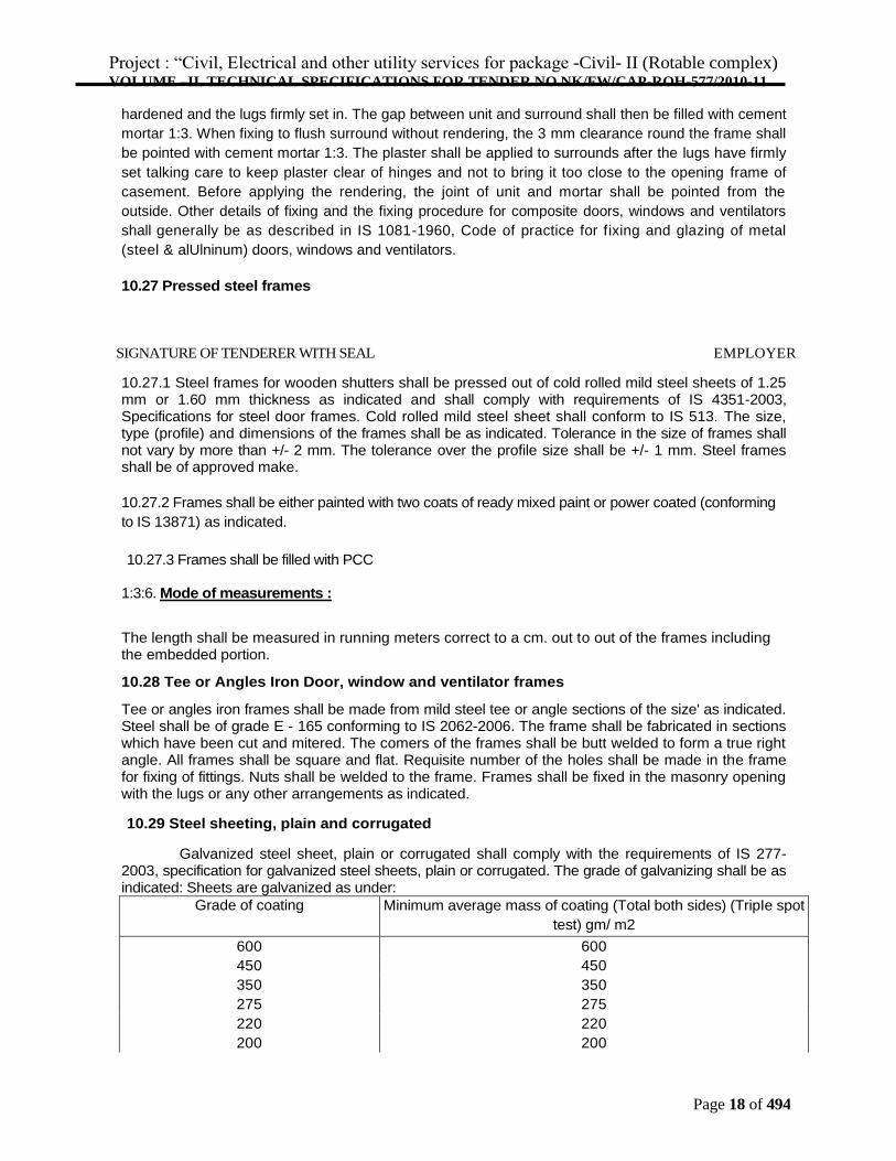
hardened and the lugs firmly set in. The gap between unit and surround shall then be filled with cement
mortar 1:3. When fixing to flush surround without rendering, the 3 mm clearance round the frame shall
be pointed with cement mortar 1:3. The plaster shall be applied to surrounds after the lugs have firmly
set talking care to keep plaster clear of hinges and not to bring it too close to the opening frame of
casement. Before applying the rendering, the joint of unit and mortar shall be pointed from the
outside. Other details of fixing and the fixing procedure for composite doors, windows and ventilators
shall generally be as described in IS 1081-1960, Code of practice for fixing and glazing of metal
(steel & alUlninum) doors, windows and ventilators.
10.27 Pressed steel frames
SIGNATURE OF TENDERER WITH SEAL EMPLOYER
10.27.1 Steel frames for wooden shutters shall be pressed out of cold rolled mild steel sheets of 1.25 mm or 1.60 mm thickness as indicated and shall comply with requirements of IS 4351-2003, Specifications for steel door frames. Cold rolled mild steel sheet shall conform to IS 513. The size, type (profile) and dimensions of the frames shall be as indicated. Tolerance in the size of frames shall not vary by more than +/- 2 mm. The tolerance over the profile size shall be +/- 1 mm. Steel frames shall be of approved make.
10.27.2 Frames shall be either painted with two coats of ready mixed paint or power coated (conforming
to IS 13871) as indicated.
10.27.3 Frames shall be filled with PCC
1:3:6. Mode of measurements :
The length shall be measured in running meters correct to a cm. out to out of the frames including the embedded portion.
10.28 Tee or Angles Iron Door, window and ventilator frames
Tee or angles iron frames shall be made from mild steel tee or angle sections of the size' as indicated. Steel shall be of grade E - 165 conforming to IS 2062-2006. The frame shall be fabricated in sections which have been cut and mitered. The comers of the frames shall be butt welded to form a true right angle. All frames shall be square and flat. Requisite number of the holes shall be made in the frame for fixing of fittings. Nuts shall be welded to the frame. Frames shall be fixed in the masonry opening with the lugs or any other arrangements as indicated.
10.29 Steel sheeting, plain and corrugated
Galvanized steel sheet, plain or corrugated shall comply with the requirements of IS 277-2003, specification for galvanized steel sheets, plain or corrugated. The grade of galvanizing shall be as indicated: Sheets are galvanized as under:
Grade of coating Minimum average mass of coating (Total both sides) (TripIe spot
test) gm/ m2
600 600
450 450
350 350
275 275
220 220
200 200
Project : “Civil, Electrical and other utility services for package -Civil- II (Rotable complex) VOLUME –II. TECHNICAL SPECIFICATIONS FOR TENDER NO.NK/FW/CAP-ROH-577/2010-11
Page 19 of 494
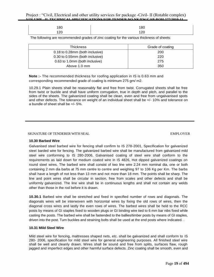
180 180
120 120 The following are recommended grades of zinc coating for the various thickness of sheets:
Thickness Grade of coating
0.18 to 0.28mm (both inclusive) 200
0.30 to 0.55mm (both inclusive) 220
0.63 to 1.0mm (both inclusive) 275
Above 1.0 mm 350
Note :- The recommended thickness for roofing application in IS is 0.63 mm and
corresponding recommended grade of coating is minimum 275 gm/ m2.
10.29.1 Plain sheets shall be reasonably flat and free from twist. Corrugated sheets shall be free from twist or buckle and shall have uniform corrugation, true in depth and pitch, and parallel to the sides of the sheets. The galvanized coating shall be clean, even and free from ungalvanised spots and other defects. The tolerance on weight of an individual sheet shall be +/- 10% and tolerance on a bundle of sheet shall be +/- 5%.
SIGNATURE OF TENDERER WITH SEAL EMPLOYER
10.30 Barbed Wire
Galvanised steel barbed wire for fencing shall confirm to IS 278-2001, Specification for galvanized
steel barded wire for fencing. The galvanized barbed wire shall be manufactured from galvanized mild
steel wire conforming to IS 280-2006, Galvanised coating of steel wire shall conform to the
requirements as laid down for medium coated wire in IS 4826, Hot dipped galvanized coatings on
round steel wires. The barbed wire shall consist of two line wire 2.24 mm nominal dia, one or both
containing 2 mm dia barbs at 75 mm centre to centre and weighing 97 to 106 Kg per Km. The barbs
shall have a length of not less than 13 mm and not more than 18 mm. The points shall be sharp. The
line and point wires shall be circular in section, free from scales and other defects and shall be
uniformly galvanized. The line wire shall be in continuous lengths and shall not contain any welds
other than those in the rod before it is drawn.
10.30.1 Barbed wire shall be stretched and fixed in specified number of rows and diagonals. The
diagonals wires will be interwoven with horizontal wires by fixing the old rows of wires, then the
diagonal cross wires and lastly the even rows of wires. The barbed wires shall be held to the RCC
posts by means of GI staples fixed to wooden plugs or GI binding wire tied to 6 mm bar nibs fixed while
casting the posts. The barbed wire shall be fastended to the ballies/timber posts by means of GI staples,
driven into the post. Turn buckles and straining bolts shall be used at the end posts where indicated. .
10.31 Mild Steel Wire
Mild steel wire for fencing, mattresses shaped nets, etc. shall be galvanized and shall conform to IS 280- 2006, specification for mild steel wire for general engineering purposes. All finished steel wire shall be well and cleanly drawn. Wires shall be sound and free from splits, surfaces flaw, rough jagged and imperfect edges and other harmful surface defects. Zinc coating shall be smooth, even and
Project : “Civil, Electrical and other utility services for package -Civil- II (Rotable complex) VOLUME –II. TECHNICAL SPECIFICATIONS FOR TENDER NO.NK/FW/CAP-ROH-577/2010-11
Page 20 of 494
bright. Fixing arrangements shall be as directed.
10.33 Welded Steel Wire Fabric.
Wire fabric for general use such as fencing, windows grills etc. shall confirm to IS 4948 – 2002, specification for welded steel wire fabric for general use. The longitudinal and transverse wire shall be securely connected at every intersection by process of welding. Wire fabric shall be rust proof and free from injurious defects. The mesh size and the size of wires shall be as indicated. Steel wire fabric in each panel shall be in one whole piece. Wire fabric shall be fixed with wooden beads or MS flats as indicated.
10.33.1 The welded steel wire fabric in fencing shall be stretched and fixed to the posts by means of G.I staple fixed to wooden plugs or G.I binding wire tied to 6 mm bar nibs, fixed while casting the posts 25 cm apart or as indicated. . 10.35 Fan Clamps
Circular cast iron box for ceiling fan clamps shall be fixed during the laying of RCC slabs. The sizes of the box shall be 10 cm overall dia, 75 mm height, with rim thickness of 5 mm. Bottom and top lid shall be 1.5 mm thick mild steel sheet with its top surface hacked for proper bonding with the concrete. Lid shall be screwed to the box. Fan clamps shall be made of 12 mm dia mild steel bar bent to shape with its end bent as directed.
10.36. ALUMINIUM WORK
Aluminium Sections:
Aluminium sections used for fixed/openable windows, ventilators, partitions, frame work & doors etc. shall be suitable for use to meet architectural designs to relevant works and shall be subject to approval of the Engineer-in-Charge for technical, structural, functional and visual considerations. Chemical and mechanical properties of sections shall comply with requirements given in IS 733-1983, Specification for wrought aluminium and aluminium alloys bars, rods and sections, IS 737-1986, Specification for wrought aluminium and aluminium alloys sheet and strip for general engineering purposes and IS 1285-2002, Specification for wrought aluminium and aluminium alloys extruded round tube and hollow sections for general engineering purposes. The stainless steel screws shall be of grade AISI 304, Joining of sections, providing fittings, lugs, method of fixing etc shall be as per IS 1948 - 1961.
The permissible dimensional tolerances of the extruded sections shall be as per IS 6477 and shall be
SIGNATURE OF TENDERER WITH SEAL EMPLOYER
such as not to impair the proper and smooth functioning/operation and appearance of door and windows.
Aluminium glazed doors, windows etc. shall be of sizes, sections and details as shown in the drawings. The details shown in the drawings may be varied slightly to suit the standards adopted by the manufacturers of the aluminium work, with the approval of Consultant and Engineer-in-Charge. Before proceeding with any fabrication work, the contractor shall prepare and submit, complete fabrication and installation drawings for each type of glazing doors, windows, ventilators and partition etc. for the approval of the Consultant and Engineer-in-Charge. If the sections are varied, the contractor shall obtain prior approval of Consultant and Engineer-inCharge and nothing extra shall be paid on this account.
Anodising:
Project : “Civil, Electrical and other utility services for package -Civil- II (Rotable complex) VOLUME –II. TECHNICAL SPECIFICATIONS FOR TENDER NO.NK/FW/CAP-ROH-577/2010-11
Page 21 of 494
Standard aluminium extrusion sections are manufactured in various sizes and shapes in wide range of solid and hollow profiles with different functional shapes for architectural, structural glazing, curtain walls, doors, window & ventilators and various other purposes. The anodizing of these products is required to be done before the fabrication work by anodizing/electro coating plants which ensures uniform coating in uniform colour and shades. The extrusions are anodized up to 30 micron in different colours. The anodized extrusions are tested regularly under strict quality control adhering to Indian Standard IS 1868 and Testing of anodizing coating shall be in accordance with IS 5523-1983.
Powder
Coating
Material:
The powder used for powder coating shall be Epoxy/polyester powder of make approved by the Engineer-in-Charge. The contractor shall give detailed programme for powder coating in advance, to facilitate the inspection by Engineer-in-Charge or his authorized representative.
Pre-treatment:
Each aluminium alloy extrusion or performed section shall be thoroughly cleaned by alkaline or acidic solutions under the conditions specified by chemical conversion coating supplier and then rinsed. A chemical conversion coating shall be applied by treatment with a solution containing essentially chromate ions or chromate and phosphate ions as the active components as applicable. The amount of the conversion coating deposited depends on the type used by the conversion coating chemical supplier. The conversion coating shall be thoroughly rinsed either with the solution specified by the conversion coating chemical supplier or with de-mineralized water and then dried at the temperature for the time specified by the conversion coating chemical supplier. The contractor shall submit the detail specifications and application procedure for application of conversion coating for approval of Engineer-inCharge. The metal surface after the conversion coating pretreatment and prior to the application of the coating shall be free from dust or powdery deposits.
Process:
The polyester powder shall be applied by electrostatic powder spray method. Before start of powder coating the contractor shall submit detail specification for application of polyester powder from manufacturer of the polyester powder for approval of Engineer-in-Charge. The powder coating shall be applied as per the specification approved by Engineer-in-Charge.
Thickness:
The thickness of the finished polyester measured by micron meter shall not be less than 55 micron and not more than 120 micron at any point.
ALUMINIUM FRAME WORK :
Frame Work:
SIGNATURE OF TENDERER WITH SEAL EMPLOYER
Project : “Civil, Electrical and other utility services for package -Civil- II (Rotable complex) VOLUME –II. TECHNICAL SPECIFICATIONS FOR TENDER NO.NK/FW/CAP-ROH-577/2010-11
Page 22 of 494
First of all the shop drawings for each type particulars shall be prepared by using suitable
sections based on architectural drawings, adequate to meet the requirement specifications and by
taking into consideration varying profiles of aluminium sections being extruded by approved
manufacturers. The shop drawings shall show full size sections of glazed doors, windows,
ventilators etc. The shop drawings shall also show the details of fittings and joints. Before start of
the work, all the shop drawings shall be got approved from the Engineer-in-Charge.
Actual measurement of openings left at site for different type of door/window etc. shall be taken.
The fabrication of the individual door/windows/ventilators etc. shall be done as per the actual
sizes of the opening left at site. The frames shall be truly rectangular and flat with regular shape
corners fabricated to true right angles. The frames shall be fabricated out of section which have
been cut to length, mitered and jointed mechanically using appropriate machines. Mitered joints
shall be corner crimped or fixed with self tapping stainless steel screws using extruded
aluminium cleats of required length and profile. All aluminium work shall provide for replacing
damaged/broken glass panes without having to remove or damage any member of exterior
finishing material.
Fixing of Frames:
The Frame work of particulars shall be fixed to Ceiling or wall with supporting materials and
devices for rigidity as approved by the Consultant and the Engineer – in – Charge. The main
and the Cross members shall be jointed with angle bracket as indicated in the fabrication
Drawing , if not indicated it shall be 15mmx15mmx1.5mm, fixed with suitable bolts, nuts and
washers etc., The panel size shall be as per the approved drawings. Fixing of Glazing Clips shall
be done carefully and no hammer markings shall be seen on the same and only wooden mallet
shall be used.
The holes in concrete/masonry/wood/any other members for fixing anchor
bolts/fasteners/screws shall be drilled with an appropriate electric drill. Windows/doors/ventilators
etc. shall be placed in correct final position in the opening and fixed to Sal wood backing using
stainless steel screws of star headed, counter sunk and matching size groove. of required size at
spacing not more than 250 mm c/c or dash fastener. All joints shall be sealed with approved
silicone sealants.
In the case of composite windows and doors, the different units are to be assembled first.
The assembled composite units shall be checked for line, level and plumb before final fixing is
done. Engineer-in-Charge in his sole discretion may allow the units to be assembled in their final
location if the situation so warrants. Snap beadings and EPDM gasket shall be fixed as per the
detail shown in the shop drawings.
Where aluminium comes into contact with stone masonry, brick work, concrete, plaster or
dissimilar metal, it shall be coated with an approved insulation lacquer, paint or plastic tape to
ensure that electrochemical corrosion is avoided. Insulation material shall be trimmed off to a
clean flush line on completion.
The contractor shall be responsible for the doors, windows etc. being set straight, plumb, level
and for their satisfactory operation after fixing is complete
Before fabrication the size of the windows and opening shall be
acertained Performance Requirements for the Finish
(i) Surface appearance:
The finish on significant surfaces shall show no scratches when illuminated and is examined at an oblique angle, no blisters, craters; pinholes or scratches shall be visible from a distance of
Project : “Civil, Electrical and other utility services for package -Civil- II (Rotable complex) VOLUME –II. TECHNICAL SPECIFICATIONS FOR TENDER NO.NK/FW/CAP-ROH-577/2010-11
Page 23 of 494
about 1 m. There shall not be any visible variation in the colour of finished surfaces of different sections and between the colours of different surfaces of same section.
(ii) Adhesion: SIGNATURE OF TENDERER WITH SEAL EMPLOYER
When a coated test piece is tested using a spacing of 2 mm between each of the six parallel cuts (the cut is made through the full depth of powder coating so that metal surface is visible) and a piece of adhesive tape, approximately 25 mm x 150 mm approved by the Engineer-in-Charge is applied firmly to the cut area and then removed rapidly by pulling at right angles to the test area, no pieces of the finish other than debris from the cutting operation shall be removed from the surface of the finish.
Protection of Powder Coated / Anodizing Finish :
It is mandatory that all aluminium members shall be wrapped with self adhesive non-staining PVC tape, approved by Engineer-in-Charge.
Measurement:
All the aluminium sections including snap beading fixed in place shall be measured in running meter along the outer periphery of composite section correct to a millimeter. The weight calculated on the basis of actual average (average of five samples) weight of composite section in kilogram correct to the second place of decimal shall be taken for payment. (Weight shall be taken after anodizing). The weight of cleat shall be added for payment. Neither any deduction nor anything extra shall be paid for skew cuts.
Rate:
The rate shall include the cost of all the materials, labours involved in all the operations as described in nomenclature of item and particular specification.