steel gate valves—flanged and butt-welding ends, bolted
TRANSCRIPT
Copyright American Petroleum Institute Provided by IHS under license with API No reproduction or networking permitted
Steel Gate Valves—Flanged and Butt-welding Ends, Bolted Bonnets
API STANDARD 600THIRTEENTH EDITION, JANUARY 2015
EFFECTIVE DATE: JULY 2015
without license from IHS
Special Notes
API publications necessarily address problems of a general nature. With respect to particular circumstances, local, state, and federal laws and regulations should be reviewed.
Neither API nor any of API's employees, subcontractors, consultants, committees, or other assignees make any warranty or representation, either express or implied, with respect to the accuracy, completeness, or usefulness of the information contained herein, or assume any liability or responsibility for any use, or the results of such use, of any information or process disclosed in this publication. Neither API nor any of API's employees, subcontractors, consultants, or other assignees represent that use of this publication would not infringe upon privately owned rights.
API publications may be used by anyone desiring to do so. Every effort has been made by the Institute to assure the accuracy and reliability of the data contained in them; however, the Institute makes no representation, warranty, or guarantee in connection with this publication and hereby expressly disclaims any liability or responsibility for loss or damage resulting from its use or for the violation of any authorities having jurisdiction with which this publication may conflict.
API publications are published to facilitate the broad availability of proven, sound engineering and operating practices. These publications are not intended to obviate the need for applying sound engineering judgment regarding when and where these publications should be utilized. The formulation and publication of API publications is not intended in any way to inhibit anyone from using any other practices.
Any manufacturer marking equipment or materials in conformance with the marking requirements of an API standard is solely responsible for complying with all the applicable requirements of that standard. API does not represent, warrant, or guarantee that such products do in fact conform to the applicable API standard.
Users of this Standard should not rely exclusively on the information contained in this document. Sound business, scientific, engineering, and safety judgment should be used in employing the information contained herein.
All rights reserved. No part of this work may be reproduced, translated, stored in a retrieval system, or transmitted by any means, electronic, mechanical, photocopying, recording, or otherwise, without prior written permission from the publisher. Contact the
Publisher, API Publishing Services, 1220 L Street, NW, Washington, DC 20005.
Copyright © 2015 American Petroleum Institute
Copyright American Petroleum Institute Provided by IHS under license with API No reproduction or networking permitted without license from IHS
Foreword
Nothing contained in any API publication is to be construed as granting any right, by implication or otherwise, for the manufacture, sale, or use of any method, apparatus, or product covered by letters patent. Neither should anything contained in the publication be construed as insuring anyone against liability for infringement of letters patent.
Shall: As used in a standard, “shall” denotes a minimum requirement in order to conform to the specification.
Should: As used in a standard, “should” denotes a recommendation or that which is advised but not required in order to conform to the specification.
This document was produced under API standardization procedures that ensure appropriate notification and participation in the developmental process and is designated as an API standard. Questions concerning the interpretation of the content of this publication or comments and questions concerning the procedures under which this publication was developed should be directed in writing to the Director of Standards, American Petroleum Institute, 1220 L Street, NW, Washington, DC 20005. Requests for permission to reproduce or translate all or any part of the material published herein should also be addressed to the director.
Generally, API standards are reviewed and revised, reaffirmed, or withdrawn at least every five years. A one-time extension of up to two years may be added to this review cycle. Status of the publication can be ascertained from the API Standards Department, telephone (202) 682-8000. A catalog of API publications and materials is published annually by API, 1220 L Street, NW, Washington, DC 20005.
Suggested revisions are invited and should be submitted to the Standards Department, API, 1220 L Street, NW, Washington, DC 20005, [email protected].
iii
Copyright American Petroleum Institute Provided by IHS under license with API No reproduction or networking permitted without license from IHS

Copyright American Petroleum Institute Provided by IHS under license with API No reproduction or networking permitted without license from IHS
Contents
Page
Copyright AmericaProvided by IHS uNo reproduction o
1 Scope . . . . . . . . . . . . . . . . . . . . . . . . . . . . . . . . . . . . . . . . . . . . . . . . . . . . . . . . . . . . . . . . . . . . . . . . . . . . . . . . . . 1
2 Normative References. . . . . . . . . . . . . . . . . . . . . . . . . . . . . . . . . . . . . . . . . . . . . . . . . . . . . . . . . . . . . . . . . . . . . 1
3 Terms and Definitions . . . . . . . . . . . . . . . . . . . . . . . . . . . . . . . . . . . . . . . . . . . . . . . . . . . . . . . . . . . . . . . . . . . . . 2
4 Pressure/Temperature Ratings . . . . . . . . . . . . . . . . . . . . . . . . . . . . . . . . . . . . . . . . . . . . . . . . . . . . . . . . . . . . . 3
5 Design. . . . . . . . . . . . . . . . . . . . . . . . . . . . . . . . . . . . . . . . . . . . . . . . . . . . . . . . . . . . . . . . . . . . . . . . . . . . . . . . . . 35.1 Body Wall Thickness. . . . . . . . . . . . . . . . . . . . . . . . . . . . . . . . . . . . . . . . . . . . . . . . . . . . . . . . . . . . . . . . . . . . . . 35.2 Bonnet Wall Thickness . . . . . . . . . . . . . . . . . . . . . . . . . . . . . . . . . . . . . . . . . . . . . . . . . . . . . . . . . . . . . . . . . . . . 45.3 Body Dimensions . . . . . . . . . . . . . . . . . . . . . . . . . . . . . . . . . . . . . . . . . . . . . . . . . . . . . . . . . . . . . . . . . . . . . . . . 45.4 Bonnet. . . . . . . . . . . . . . . . . . . . . . . . . . . . . . . . . . . . . . . . . . . . . . . . . . . . . . . . . . . . . . . . . . . . . . . . . . . . . . . . . . 85.5 Bonnet-to-body Joint . . . . . . . . . . . . . . . . . . . . . . . . . . . . . . . . . . . . . . . . . . . . . . . . . . . . . . . . . . . . . . . . . . . . . 85.6 Gate . . . . . . . . . . . . . . . . . . . . . . . . . . . . . . . . . . . . . . . . . . . . . . . . . . . . . . . . . . . . . . . . . . . . . . . . . . . . . . . . . . . . 95.7 Yoke. . . . . . . . . . . . . . . . . . . . . . . . . . . . . . . . . . . . . . . . . . . . . . . . . . . . . . . . . . . . . . . . . . . . . . . . . . . . . . . . . . . 105.8 Stem and Stem Nut . . . . . . . . . . . . . . . . . . . . . . . . . . . . . . . . . . . . . . . . . . . . . . . . . . . . . . . . . . . . . . . . . . . . . . 115.9 Packing and Packing Box. . . . . . . . . . . . . . . . . . . . . . . . . . . . . . . . . . . . . . . . . . . . . . . . . . . . . . . . . . . . . . . . . 145.10 Bolting. . . . . . . . . . . . . . . . . . . . . . . . . . . . . . . . . . . . . . . . . . . . . . . . . . . . . . . . . . . . . . . . . . . . . . . . . . . . . . . . . 155.11 Operation . . . . . . . . . . . . . . . . . . . . . . . . . . . . . . . . . . . . . . . . . . . . . . . . . . . . . . . . . . . . . . . . . . . . . . . . . . . . . . 155.12 Bypasses and Other Auxiliary Connections . . . . . . . . . . . . . . . . . . . . . . . . . . . . . . . . . . . . . . . . . . . . . . . . . 15
6 Materials . . . . . . . . . . . . . . . . . . . . . . . . . . . . . . . . . . . . . . . . . . . . . . . . . . . . . . . . . . . . . . . . . . . . . . . . . . . . . . . 166.1 Materials Other Than Trim Materials . . . . . . . . . . . . . . . . . . . . . . . . . . . . . . . . . . . . . . . . . . . . . . . . . . . . . . . . 166.2 Trim . . . . . . . . . . . . . . . . . . . . . . . . . . . . . . . . . . . . . . . . . . . . . . . . . . . . . . . . . . . . . . . . . . . . . . . . . . . . . . . . . . 17
7 Testing, Inspection and Examination . . . . . . . . . . . . . . . . . . . . . . . . . . . . . . . . . . . . . . . . . . . . . . . . . . . . . . . 177.1 Inspection and Examination. . . . . . . . . . . . . . . . . . . . . . . . . . . . . . . . . . . . . . . . . . . . . . . . . . . . . . . . . . . . . . . 177.2 Pressure Tests . . . . . . . . . . . . . . . . . . . . . . . . . . . . . . . . . . . . . . . . . . . . . . . . . . . . . . . . . . . . . . . . . . . . . . . . . . 177.3 Repairs of Defects . . . . . . . . . . . . . . . . . . . . . . . . . . . . . . . . . . . . . . . . . . . . . . . . . . . . . . . . . . . . . . . . . . . . . . . 17
8 Marking . . . . . . . . . . . . . . . . . . . . . . . . . . . . . . . . . . . . . . . . . . . . . . . . . . . . . . . . . . . . . . . . . . . . . . . . . . . . . . . 218.1 General . . . . . . . . . . . . . . . . . . . . . . . . . . . . . . . . . . . . . . . . . . . . . . . . . . . . . . . . . . . . . . . . . . . . . . . . . . . . . . . . 218.2 Marking for Unidirectional Valves . . . . . . . . . . . . . . . . . . . . . . . . . . . . . . . . . . . . . . . . . . . . . . . . . . . . . . . . . . 21
9 Preparation for Shipment . . . . . . . . . . . . . . . . . . . . . . . . . . . . . . . . . . . . . . . . . . . . . . . . . . . . . . . . . . . . . . . . . 219.1 Coatings . . . . . . . . . . . . . . . . . . . . . . . . . . . . . . . . . . . . . . . . . . . . . . . . . . . . . . . . . . . . . . . . . . . . . . . . . . . . . . . 219.2 Openings . . . . . . . . . . . . . . . . . . . . . . . . . . . . . . . . . . . . . . . . . . . . . . . . . . . . . . . . . . . . . . . . . . . . . . . . . . . . . . 219.3 Gate Position . . . . . . . . . . . . . . . . . . . . . . . . . . . . . . . . . . . . . . . . . . . . . . . . . . . . . . . . . . . . . . . . . . . . . . . . . . . 219.4 Stem Packing . . . . . . . . . . . . . . . . . . . . . . . . . . . . . . . . . . . . . . . . . . . . . . . . . . . . . . . . . . . . . . . . . . . . . . . . . . . 229.5 Packaging. . . . . . . . . . . . . . . . . . . . . . . . . . . . . . . . . . . . . . . . . . . . . . . . . . . . . . . . . . . . . . . . . . . . . . . . . . . . . . 229.6 Purchase Order Information. . . . . . . . . . . . . . . . . . . . . . . . . . . . . . . . . . . . . . . . . . . . . . . . . . . . . . . . . . . . . . . 22
Annex A (informative) API Monogram Program Use of the API Monogram by Licensees . . . . . . . . . . . . . . . . . 23
Annex B (normative) Information to be Specified by the Purchaser . . . . . . . . . . . . . . . . . . . . . . . . . . . . . . . . . . . 27
Annex C (informative) Identification of Valve Terms . . . . . . . . . . . . . . . . . . . . . . . . . . . . . . . . . . . . . . . . . . . . . . . . 29
Annex D (informative) Valve Material Combinations . . . . . . . . . . . . . . . . . . . . . . . . . . . . . . . . . . . . . . . . . . . . . . . . 30
Bibliography 33
v
n Petroleum Institute nder license with API r networking permitted without license from IHS
Contents
Page
Copyright AmericaProvided by IHS uNo reproduction o
Figures1 Identification of Terms . . . . . . . . . . . . . . . . . . . . . . . . . . . . . . . . . . . . . . . . . . . . . . . . . . . . . . . . . . . . . . . . . . . . 42 Types of Valve Gates. . . . . . . . . . . . . . . . . . . . . . . . . . . . . . . . . . . . . . . . . . . . . . . . . . . . . . . . . . . . . . . . . . . . . 103 Wear Travel. . . . . . . . . . . . . . . . . . . . . . . . . . . . . . . . . . . . . . . . . . . . . . . . . . . . . . . . . . . . . . . . . . . . . . . . . . . . . 11C.1 Valve Nomenclature . . . . . . . . . . . . . . . . . . . . . . . . . . . . . . . . . . . . . . . . . . . . . . . . . . . . . . . . . . . . . . . . . . . . . 29
Tables1 Minimum Wall Thickness for Body and Bonnet. . . . . . . . . . . . . . . . . . . . . . . . . . . . . . . . . . . . . . . . . . . . . . . . 52 Post Weld Heat Treatment for Flange to Body Weld . . . . . . . . . . . . . . . . . . . . . . . . . . . . . . . . . . . . . . . . . . . . 63 Minimum Inside Diameter for Sizes DN 800 to DN 1050 (NPS 32 to NPS 42) in Classes 150 and 300 . . . 74 Minimum Wear Travel and Maximum Stem Projection . . . . . . . . . . . . . . . . . . . . . . . . . . . . . . . . . . . . . . . . . 115 Minimum Stem Diameter . . . . . . . . . . . . . . . . . . . . . . . . . . . . . . . . . . . . . . . . . . . . . . . . . . . . . . . . . . . . . . . . . 125A Permitted Undertolerance . . . . . . . . . . . . . . . . . . . . . . . . . . . . . . . . . . . . . . . . . . . . . . . . . . . . . . . . . . . . . . . . 136 Nominal Radial Width of Packing . . . . . . . . . . . . . . . . . . . . . . . . . . . . . . . . . . . . . . . . . . . . . . . . . . . . . . . . . . 147 Materials for Parts . . . . . . . . . . . . . . . . . . . . . . . . . . . . . . . . . . . . . . . . . . . . . . . . . . . . . . . . . . . . . . . . . . . . . . . 168 Nominal Seating Surface, Stem and Backseat Bushing or Weld-deposit Materials and Hardness . . . . 189 Trim Numbers and Alternative Trim Numbers . . . . . . . . . . . . . . . . . . . . . . . . . . . . . . . . . . . . . . . . . . . . . . . . 21D.1 Material Combinations for Group 1 Body, Bonnet and Cover Materials. . . . . . . . . . . . . . . . . . . . . . . . . . . 30D.2 Material Combinations for Group 2 Body to Bonnet Materials . . . . . . . . . . . . . . . . . . . . . . . . . . . . . . . . . . 31D.3 Alternative Body to Bonnet Bolting Materials . . . . . . . . . . . . . . . . . . . . . . . . . . . . . . . . . . . . . . . . . . . . . . . . 32
vi
n Petroleum Institute nder license with API r networking permitted without license from IHS
Copyright AmericaProvided by IHS uNo reproduction o
Steel Gate Valves—Flanged and Butt-welding Ends, Bolted Bonnets
1 Scope
This standard specifies the requirements for a heavy-duty series of bolted bonnet steel gate valves for petroleum refinery and related applications where corrosion, erosion, and other service conditions would indicate a need for full port openings, heavy wall sections, and large stem diameters.
This standard sets forth the requirements for the following gate valve features:
— bolted bonnet,
— outside screw and yoke,
— rising stems,
— non-rising handwheels,
— single or double gate,
— wedge or parallel seating,
— metallic seating surfaces,
— flanged or butt-welding ends.
It covers valves of the nominal pipe sizes DN:
— 25, 32, 40, 50, 65, 80, 100, 150, 200, 250, 300, 350, 400, 450, 500, 600, 650, 700, 750, 800, 850, 900, 950, 1000, 1050;
corresponding to nominal pipe sizes NPS:
— 1, 1 1/4, 1 1/2, 2, 2 1/2, 3, 4, 6, 8, 10, 12, 14, 16, 18, 20, 24, 26, 28, 30, 32, 34, 36, 38, 40, 42;
and applies to pressure class designations:
— 150, 300, 600, 900, 1500, 2500.
If product is supplied bearing the API Monogram and manufactured at a facility licensed by API, the requirements of Annex A apply.
2 Normative References
The following referenced documents are indispensable for the application of this document. For dated references, only the edition cited applies. For undated references, the latest edition of the referenced document (including any amendments) applies.
API Standard 598, Valve Inspection and Testing
API Standard 624, Type Testing of Rising Stem Valves Equipped with Graphite Packing for Fugitive Emissions
ASME B1.1 1, Unified Inch Screw Threads (UN and UNR Thread Form)
1 ASME International, 2 Park Avenue, New York, New York 10016-5990, www.asme.org.
1
n Petroleum Institute nder license with API r networking permitted without license from IHS
2 API STANDARD 600
Copyright AmProvided by No reproduc
ASME B1.5, Acme Screw Threads
ASME B1.8, Stub Acme Screw Threads
ASME B1.12, Class 5 Interference—Fit Thread
ASME B1.13M, Metric Screw Threads: M Profile
ASME B16.5, Pipe Flanges and Flanged Fittings NPS 1/2 through NPS 24 Metric/Inch
ASME B16.10, Face-to Face and End-to-End Dimensions of Valves
ASME B16.25, Buttwelding Ends
ASME B16.34, Valves—Flanged, Threaded and Welding End
ASME B16.47, Large Diameter Steel Flanges, NPS 26 Through NPS 60 Metric/Inch Standard
ASME B18.2.2, Nuts for General Applications: Machine Screw Nuts, Hex, Square, Hex Flange, and Coupling Nuts (Inch Series)
ASME B18.2.6M, Metric Fasteners for Use in Structural Applications
ASME B31.3, Process Piping
ISO 5210 2, Industrial valves—Multi-turn valve actuator attachments
ISO 5752, Metal valves for use in flanged pipe systems—Face-to-face and centre-to-face dimensions
ISO 15649, Petroleum and natural gas industries—Piping
MSS SP-91 3, Guidelines for Manual Operation of Valves
MSS SP-102, Multi-Turn Valve Actuator Attachment—Flange and Driving Component Dimensions and Performance Characteristics
MSS SP-144, Pressure Seal Bonnet Valves
3 Terms and Definitions
For the purposes of this document, the following definitions apply.
3.1ClassAn alphanumeric designation that is used for reference purposes relating to valve pressure/temperature capability, taking into account valve material mechanical properties and valve dimensional characteristics. It comprises “Class” followed by a dimensionless whole number. The number following “Class” does not represent a measurable value and is not used for calculation purposes except where specified in this standard. The allowable pressure for a valve
2 International Organization for Standardization, 1, ch. de la Voie-Creuse, Case postale 56, CH-1211, Geneva 20, Switzerland, www.iso.org.
3 Manufacturers Standardization Society of the Valve and Fittings Industry, Inc., 127 Park Street, NE, Vienna, Virginia 22180-4602, www.mss-hq.com.
erican Petroleum Institute IHS under license with API tion or networking permitted without license from IHS
STEEL GATE VALVES—FLANGED AND BUTT-WELDING ENDS, BOLTED BONNETS 3
Copyright AmericaProvided by IHS uNo reproduction o
having a class number depends on the valve material and its application temperature and is to be found in tables of pressure/temperature ratings.
3.2DNAn alpha numeric designation of size that is common for components used in a piping system, used for reference purposes, comprising the letters “DN” followed by a dimensionless number indirectly related to the physical size of the bore or outside diameter of the end connection as appropriate. The dimensionless number following “DN” does not represent a measurable value and is not used for calculation purposes except where specified.
3.3NPSAn alpha numeric designation of size that is common for components used in a piping system, used for reference purposes, comprising the letters “NPS” followed by a dimensionless number indirectly related to the physical size of the bore or outside diameter of the end connection as appropriate. The dimensionless number may be used as a valve size identifier without the prefix “NPS.” The dimensionless size identification number does not represent a measurable value and is not used for calculation purposes.
3.4ShellComprised of the body, bonnet and body-bonnet bolting which constitute the pressure boundary of an API 600 valve.
4 Pressure/Temperature Ratings
4.1 Pressure/temperature ratings shall be in accordance with those specified in the tables of ASME B16.34 for standard class for the applicable material specification and the applicable class.
4.2 Restrictions of temperature and concurrent pressure, or pressure and concurrent temperature, (e.g. those imposed by special soft seals or special trim materials), shall be marked on the valve identification plate (see Section 8).
4.3 The temperature for a corresponding pressure rating is the maximum temperature of the pressure-containing shell of the valve. In general, this temperature is the same as that of the contained fluid. The use of a pressure rating corresponding to a temperature other than that of the contained fluid is the responsibility of the user.
4.4 For temperatures below the lowest temperature listed in the pressure/temperature tables, the service pressure shall be no greater than the pressure for the lowest listed temperature. The use of valves at lower temperatures is the responsibility of the user. Consideration should be given to the loss of ductility and impact strength of many materials at low temperature.
4.5 Double seated valves, in some design configurations, may be capable of trapping liquid in the center cavity of the valve when in the closed position. If subjected to an increase in temperature, an excessive build-up of pressure can occur, which may result in a pressure boundary failure. Where such a condition is possible, it is the responsibility of the user to provide or require to be provided, means in design, installation, or operating procedure, to assure that the pressure in the valve does not exceed that allowed by this standard for the resultant temperature.
5 Design
5.1 Body Wall Thickness
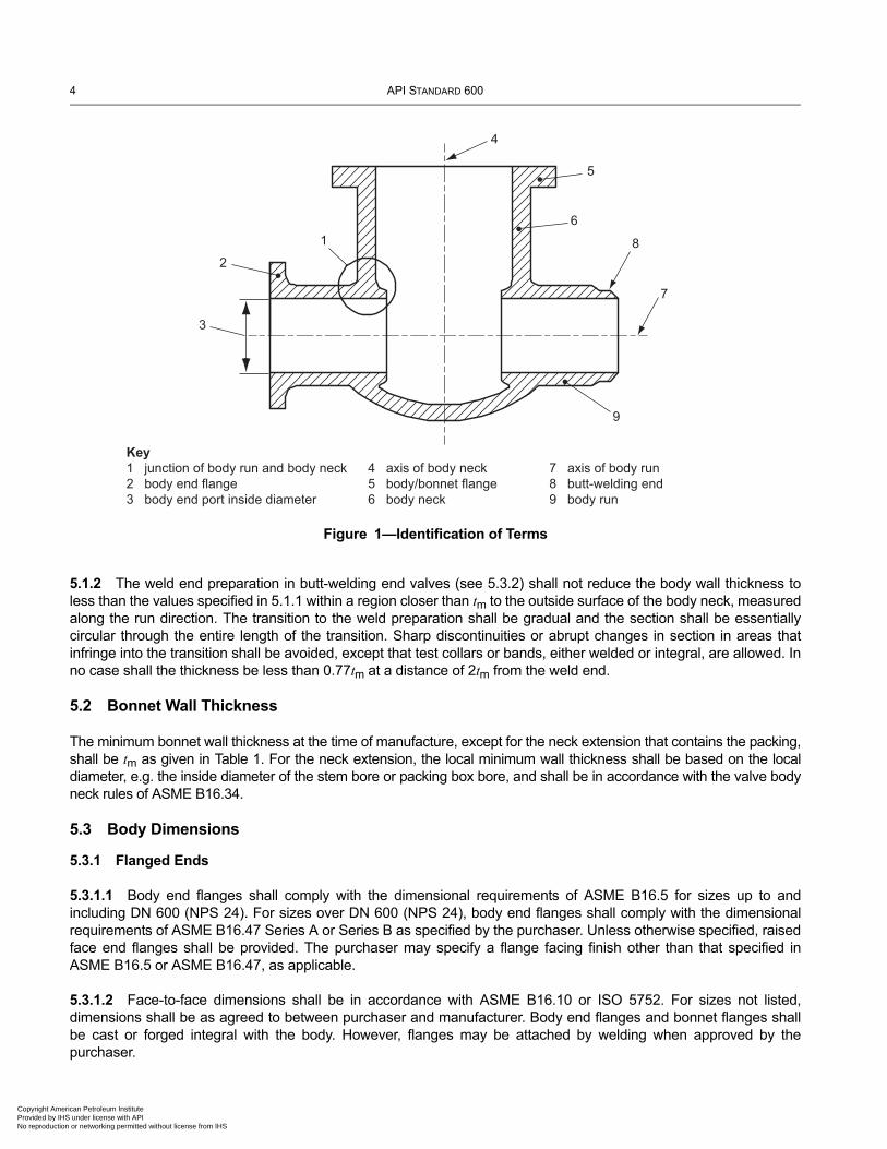
5.1.1 A valve body schematic is shown as Figure 1. The minimum body wall thickness, tm, at the time of manufacture shall be as given in Table 1, except as indicated in 5.1.2 for butt-welding valve ends. Additional metal thickness needed for assembly stresses, stress concentrations, and shapes other than circular shall be determined by individual manufacturers, since these factors vary widely.
n Petroleum Institute nder license with API r networking permitted without license from IHS
4 API STANDARD 600
Copyright AmProvided by No reproduc
5.1.2 The weld end preparation in butt-welding end valves (see 5.3.2) shall not reduce the body wall thickness to less than the values specified in 5.1.1 within a region closer than tm to the outside surface of the body neck, measured along the run direction. The transition to the weld preparation shall be gradual and the section shall be essentially circular through the entire length of the transition. Sharp discontinuities or abrupt changes in section in areas that infringe into the transition shall be avoided, except that test collars or bands, either welded or integral, are allowed. In no case shall the thickness be less than 0.77tm at a distance of 2tm from the weld end.
5.2 Bonnet Wall Thickness
The minimum bonnet wall thickness at the time of manufacture, except for the neck extension that contains the packing, shall be tm as given in Table 1. For the neck extension, the local minimum wall thickness shall be based on the local diameter, e.g. the inside diameter of the stem bore or packing box bore, and shall be in accordance with the valve body neck rules of ASME B16.34.
5.3 Body Dimensions
5.3.1 Flanged Ends
5.3.1.1 Body end flanges shall comply with the dimensional requirements of ASME B16.5 for sizes up to and including DN 600 (NPS 24). For sizes over DN 600 (NPS 24), body end flanges shall comply with the dimensional requirements of ASME B16.47 Series A or Series B as specified by the purchaser. Unless otherwise specified, raised face end flanges shall be provided. The purchaser may specify a flange facing finish other than that specified in ASME B16.5 or ASME B16.47, as applicable.
5.3.1.2 Face-to-face dimensions shall be in accordance with ASME B16.10 or ISO 5752. For sizes not listed, dimensions shall be as agreed to between purchaser and manufacturer. Body end flanges and bonnet flanges shall be cast or forged integral with the body. However, flanges may be attached by welding when approved by the purchaser.
Figure 1—Identification of Terms
1
2
3
4
9
7
8
6
5
Key1 junction of body run and body neck 4 axis of body neck 7 axis of body run2 body end flange 5 body/bonnet flange 8 butt-welding end3 body end port inside diameter 6 body neck 9 body run
erican Petroleum Institute IHS under license with API tion or networking permitted without license from IHS
STEEL GATE VALVES—FLANGED AND BUTT-WELDING ENDS, BOLTED BONNETS 5
Copyright AmericaProvided by IHS uNo reproduction o
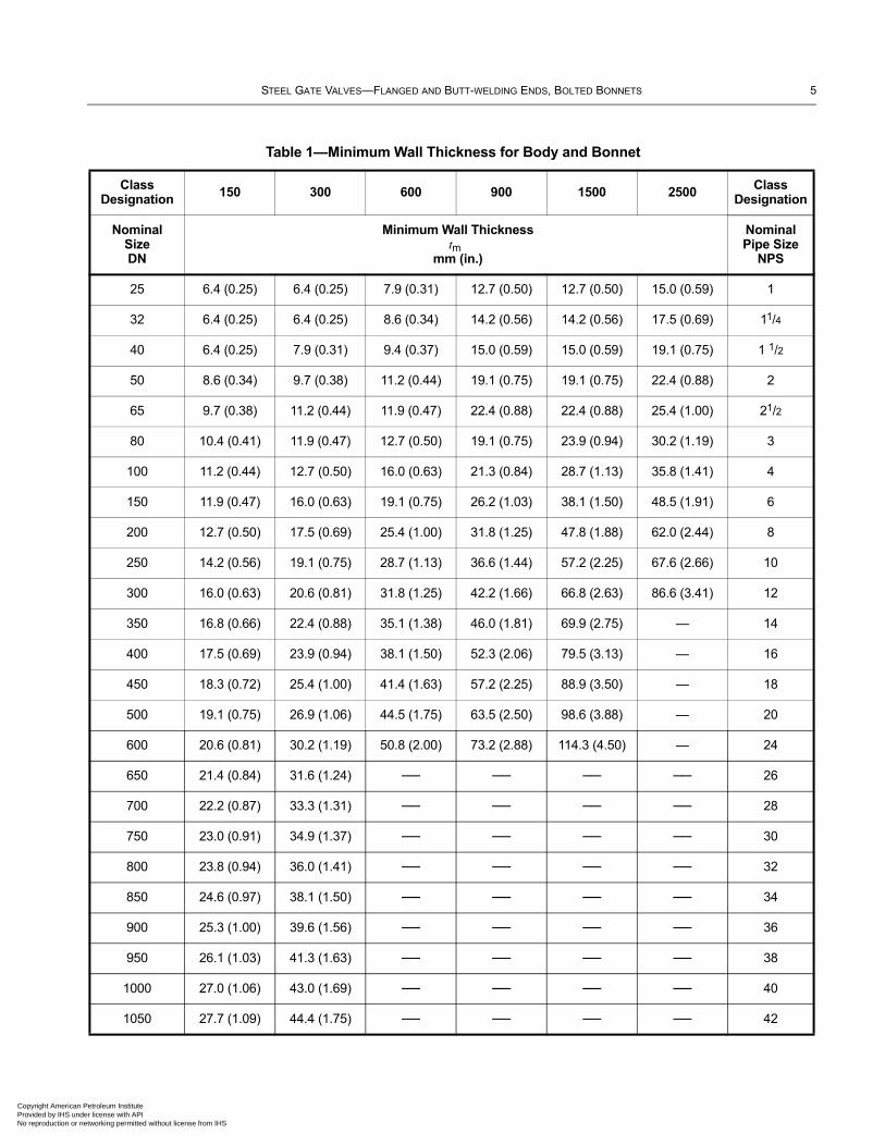
Table 1—Minimum Wall Thickness for Body and Bonnet
Class Designation
150 300 600 900 1500 2500 Class Designation
Nominal Size DN
Minimum Wall Thicknesstm
mm (in.)
Nominal Pipe Size
NPS
25 6.4 (0.25) 6.4 (0.25) 7.9 (0.31) 12.7 (0.50) 12.7 (0.50) 15.0 (0.59) 1
32 6.4 (0.25) 6.4 (0.25) 8.6 (0.34) 14.2 (0.56) 14.2 (0.56) 17.5 (0.69) 11/4
40 6.4 (0.25) 7.9 (0.31) 9.4 (0.37) 15.0 (0.59) 15.0 (0.59) 19.1 (0.75) 1 1/2
50 8.6 (0.34) 9.7 (0.38) 11.2 (0.44) 19.1 (0.75) 19.1 (0.75) 22.4 (0.88) 2
65 9.7 (0.38) 11.2 (0.44) 11.9 (0.47) 22.4 (0.88) 22.4 (0.88) 25.4 (1.00) 21/2
80 10.4 (0.41) 11.9 (0.47) 12.7 (0.50) 19.1 (0.75) 23.9 (0.94) 30.2 (1.19) 3
100 11.2 (0.44) 12.7 (0.50) 16.0 (0.63) 21.3 (0.84) 28.7 (1.13) 35.8 (1.41) 4
150 11.9 (0.47) 16.0 (0.63) 19.1 (0.75) 26.2 (1.03) 38.1 (1.50) 48.5 (1.91) 6
200 12.7 (0.50) 17.5 (0.69) 25.4 (1.00) 31.8 (1.25) 47.8 (1.88) 62.0 (2.44) 8
250 14.2 (0.56) 19.1 (0.75) 28.7 (1.13) 36.6 (1.44) 57.2 (2.25) 67.6 (2.66) 10
300 16.0 (0.63) 20.6 (0.81) 31.8 (1.25) 42.2 (1.66) 66.8 (2.63) 86.6 (3.41) 12
350 16.8 (0.66) 22.4 (0.88) 35.1 (1.38) 46.0 (1.81) 69.9 (2.75) — 14
400 17.5 (0.69) 23.9 (0.94) 38.1 (1.50) 52.3 (2.06) 79.5 (3.13) — 16
450 18.3 (0.72) 25.4 (1.00) 41.4 (1.63) 57.2 (2.25) 88.9 (3.50) — 18
500 19.1 (0.75) 26.9 (1.06) 44.5 (1.75) 63.5 (2.50) 98.6 (3.88) — 20
600 20.6 (0.81) 30.2 (1.19) 50.8 (2.00) 73.2 (2.88) 114.3 (4.50) — 24
650 21.4 (0.84) 31.6 (1.24) ── ── ── ── 26
700 22.2 (0.87) 33.3 (1.31) ── ── ── ── 28
750 23.0 (0.91) 34.9 (1.37) ── ── ── ── 30
800 23.8 (0.94) 36.0 (1.41) ── ── ── ── 32
850 24.6 (0.97) 38.1 (1.50) ── ── ── ── 34
900 25.3 (1.00) 39.6 (1.56) ── ── ── ── 36
950 26.1 (1.03) 41.3 (1.63) ── ── ── ── 38
1000 27.0 (1.06) 43.0 (1.69) ── ── ── ── 40
1050 27.7 (1.09) 44.4 (1.75) ── ── ── ── 42
n Petroleum Institute nder license with API r networking permitted without license from IHS
6 API STANDARD 600
Copyright AmProvided by No reproduc
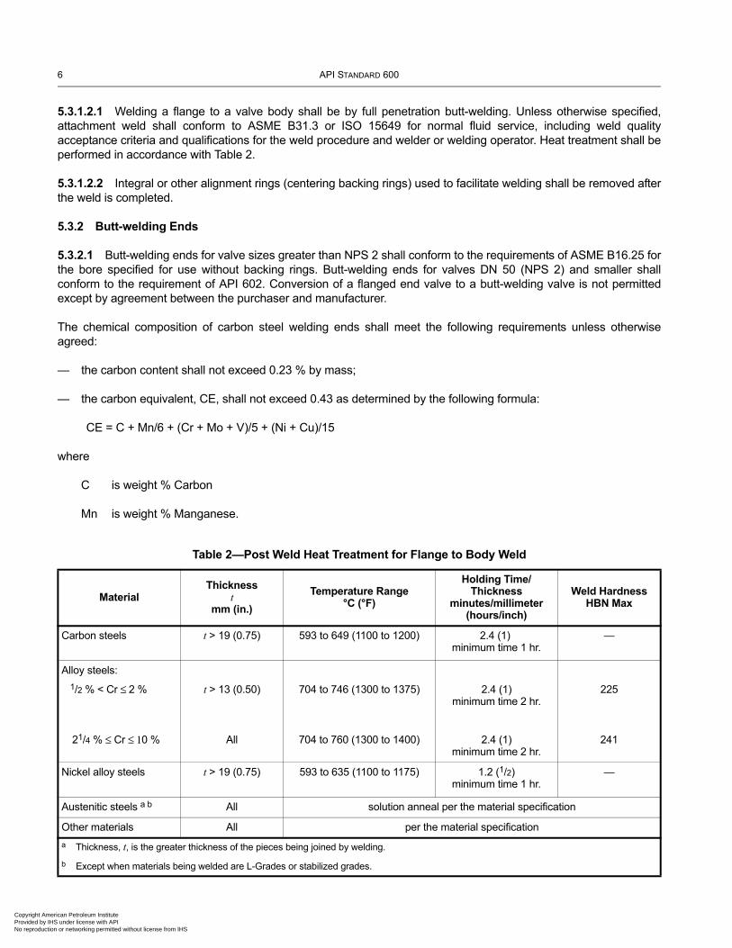
5.3.1.2.1 Welding a flange to a valve body shall be by full penetration butt-welding. Unless otherwise specified, attachment weld shall conform to ASME B31.3 or ISO 15649 for normal fluid service, including weld quality acceptance criteria and qualifications for the weld procedure and welder or welding operator. Heat treatment shall be performed in accordance with Table 2.
5.3.1.2.2 Integral or other alignment rings (centering backing rings) used to facilitate welding shall be removed after the weld is completed.
5.3.2 Butt-welding Ends
5.3.2.1 Butt-welding ends for valve sizes greater than NPS 2 shall conform to the requirements of ASME B16.25 for the bore specified for use without backing rings. Butt-welding ends for valves DN 50 (NPS 2) and smaller shall conform to the requirement of API 602. Conversion of a flanged end valve to a butt-welding valve is not permitted except by agreement between the purchaser and manufacturer.
The chemical composition of carbon steel welding ends shall meet the following requirements unless otherwise agreed:
— the carbon content shall not exceed 0.23 % by mass;
— the carbon equivalent, CE, shall not exceed 0.43 as determined by the following formula:
CE = C + Mn/6 + (Cr + Mo + V)/5 + (Ni + Cu)/15
where
C is weight % Carbon
Mn is weight % Manganese.
Table 2—Post Weld Heat Treatment for Flange to Body Weld
MaterialThickness
tmm (in.)
Temperature Range°C (°F)
Holding Time/Thickness
minutes/millimeter (hours/inch)
Weld HardnessHBN Max
Carbon steels t > 19 (0.75) 593 to 649 (1100 to 1200) 2.4 (1) minimum time 1 hr.
—
Alloy steels:
1/2 % < Cr ≤ 2 %
21/4 % ≤ Cr ≤ 10 %
t > 13 (0.50)
All
704 to 746 (1300 to 1375)
704 to 760 (1300 to 1400)
2.4 (1)minimum time 2 hr.
2.4 (1)minimum time 2 hr.
225
241
Nickel alloy steels t > 19 (0.75) 593 to 635 (1100 to 1175) 1.2 (1/2)minimum time 1 hr.
—
Austenitic steels a b All solution anneal per the material specification
Other materials All per the material specification
a Thickness, t, is the greater thickness of the pieces being joined by welding.
b Except when materials being welded are L-Grades or stabilized grades.
erican Petroleum Institute IHS under license with API tion or networking permitted without license from IHS
STEEL GATE VALVES—FLANGED AND BUTT-WELDING ENDS, BOLTED BONNETS 7
Copyright AmericaProvided by IHS uNo reproduction o
Cr is weight % Chromium
Mo is weight % Molybdenum
V is weight % Vanadium
Ni is weight % Nickel
Cu is weight % Copper
5.3.2.2 End-to-end dimensions for butt-welding end class designated valves shall be in accordance with ASME B16.10, unless otherwise specified by the purchaser.
5.3.3 Body Seats
5.3.3.1 The inside diameter of the seat opening shall not be less than that specified below:
— for all Classes in sizes up to DN 600 (NPS 24), ASME B16.34;
— for Classes 150 and 300 in sizes DN 650 to DN 750 (NPS 26 to NPS 30), ASME B16.34;
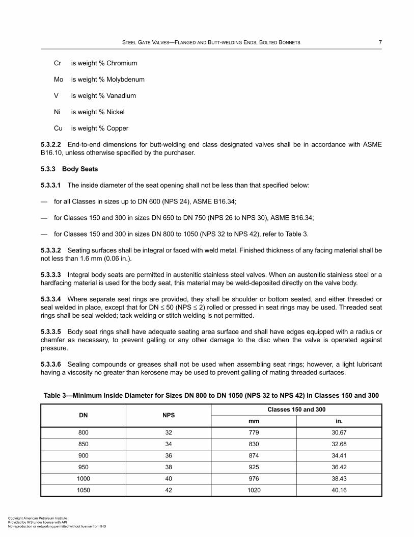
— for Classes 150 and 300 in sizes DN 800 to 1050 (NPS 32 to NPS 42), refer to Table 3.
5.3.3.2 Seating surfaces shall be integral or faced with weld metal. Finished thickness of any facing material shall be not less than 1.6 mm (0.06 in.).
5.3.3.3 Integral body seats are permitted in austenitic stainless steel valves. When an austenitic stainless steel or a hardfacing material is used for the body seat, this material may be weld-deposited directly on the valve body.
5.3.3.4 Where separate seat rings are provided, they shall be shoulder or bottom seated, and either threaded or seal welded in place, except that for DN ≤ 50 (NPS ≤ 2) rolled or pressed in seat rings may be used. Threaded seat rings shall be seal welded; tack welding or stitch welding is not permitted.
5.3.3.5 Body seat rings shall have adequate seating area surface and shall have edges equipped with a radius or chamfer as necessary, to prevent galling or any other damage to the disc when the valve is operated against pressure.
5.3.3.6 Sealing compounds or greases shall not be used when assembling seat rings; however, a light lubricant having a viscosity no greater than kerosene may be used to prevent galling of mating threaded surfaces.
Table 3—Minimum Inside Diameter for Sizes DN 800 to DN 1050 (NPS 32 to NPS 42) in Classes 150 and 300
DN NPSClasses 150 and 300
mm in.
800 32 779 30.67
850 34 830 32.68
900 36 874 34.41
950 38 925 36.42
1000 40 976 38.43
1050 42 1020 40.16
n Petroleum Institute nder license with API r networking permitted without license from IHS
8 API STANDARD 600
Copyright AmProvided by No reproduc
5.4 Bonnet
5.4.1 When designing the stem, gland, lantern ring (if supplied) and backseat, the manufacturer shall take into account stem guiding and the prevention of packing extrusion.
5.4.2 The bonnet shall include a conical or spherical stem backseat in one of the following forms:
— a bushing positively secured against coming loose, i.e. not relying on friction;
— an integral surface in the case of an austenitic stainless steel valve;
— an austenitic stainless steel or hardfaced weld deposit that is a minimum of 1.6 mm (0.06 in.) thick.
5.4.3 Bonnets shall be one-piece castings or forgings.
5.4.4 The gland bolting shall be secured to the bonnet so that the bolting is retained during repacking. When eyebolts are used, the eyebolt pin shall be anchored on both sides of the eyebolt. The anchors shall not include open slotted holes or be attached by fillet welds.
5.4.5 Tapped test openings shall be provided only if specified in the purchase order.
5.5 Bonnet-to-body Joint
5.5.1 The bonnet-to-body joint shall be a flange and gasket type.
5.5.2 For Class 150 valves, the bonnet-to-body joint shall be one of the following types illustrated in ASME B16.5:
— flat face;
— raised face;
— tongue and groove;
— spigot and recess (i.e. male and female);
— ring joint.
5.5.3 For valves having pressure class designation Class > 150, the bonnet-to-body joint shall be as in 5.5.2, except that the flat face joint is not permitted.
5.5.4 The bonnet flange gasket shall be one of the following:
— solid metal, corrugated or grooved (profiled) metal gasket with graphite filler;
— metal ring joint;
— spiral wound metal gasket with filler and a centering/compression ring;
— spiral wound metal gasket with filler but without a centering/compression ring, to be used only in ‘tongue and groove’ or ‘spigot and recess’ joints that prevent the gasket from unwinding and from buckling damage.
erican Petroleum Institute IHS under license with API tion or networking permitted without license from IHS
STEEL GATE VALVES—FLANGED AND BUTT-WELDING ENDS, BOLTED BONNETS 9
Copyright AmericaProvided by IHS uNo reproduction o
For Class 150, the following are also acceptable:
— corrugated metal insert with graphite facings;
— when approved by the purchaser, flexible graphite sheet, reinforced with a stainless steel flat, perforated, tanged, or corrugated insert equipped with annular containment rings;
— when approved by the purchaser, other suitable facings may be used.
5.5.5 Except for Class 150, the gasket shall not extend beyond the inner edge of the bolt holes.
5.5.6 Except for Class 150 valves and valves in sizes DN 65 (NPS 21/2) and smaller, bonnet-to-body flanges shall be circular.
5.5.7 Bonnet and body flange nut bearing surfaces shall be parallel to the flange face within ±1°. Spot facing or back-facing required to meet the parallelism requirement shall be in accordance with ASME B16.5.
5.5.8 The bonnet-to-body joint shall be secured by a minimum of four through type stud bolts. The minimum stud bolt size for each valve size shall be as follows:
— M10 or 3/8 when 25 ≤ DN ≤ 65 (1 ≤ NPS ≤ 21/2);
— M12 or 1/2 when 80 ≤ DN ≤ 200 (3 ≤ NPS ≤ 8);
— M16 or 5/8 when DN ≥ 250 (NPS ≥ 10).
5.5.9 The total cross-sectional area of the bolts in valve bonnet bolting shall be in accordance with the requirements of ASME B16.34.
5.5.10 At assembly, gasket contact surfaces shall be free of sealing compounds. A light coating of a lubricant, no heavier than kerosene, may be applied if needed to assist in proper gasket assembly.
5.5.11 If pressure seal bonnet design is specified, the bonnet joint construction shall be in accordance with MSS SP-144 Style B, unless otherwise specified by the purchaser.
5.6 Gate
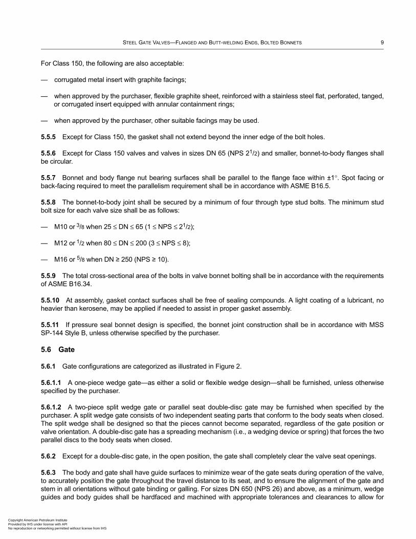
5.6.1 Gate configurations are categorized as illustrated in Figure 2.
5.6.1.1 A one-piece wedge gate—as either a solid or flexible wedge design—shall be furnished, unless otherwise specified by the purchaser.
5.6.1.2 A two-piece split wedge gate or parallel seat double-disc gate may be furnished when specified by the purchaser. A split wedge gate consists of two independent seating parts that conform to the body seats when closed. The split wedge shall be designed so that the pieces cannot become separated, regardless of the gate position or valve orientation. A double-disc gate has a spreading mechanism (i.e., a wedging device or spring) that forces the two parallel discs to the body seats when closed.
5.6.2 Except for a double-disc gate, in the open position, the gate shall completely clear the valve seat openings.
5.6.3 The body and gate shall have guide surfaces to minimize wear of the gate seats during operation of the valve, to accurately position the gate throughout the travel distance to its seat, and to ensure the alignment of the gate and stem in all orientations without gate binding or galling. For sizes DN 650 (NPS 26) and above, as a minimum, wedge guides and body guides shall be hardfaced and machined with appropriate tolerances and clearances to allow for
n Petroleum Institute nder license with API r networking permitted without license from IHS
10 API STANDARD 600
Copyright AmProvided by No reproduc
proper valve operation in any orientation, including effects of wear or galling. Wedge guides and/or body guides shall not protrude beyond the seat rings into the port area of the valve. The manufacturer shall provide in their installation and operation manual any operational limitations as a result of stem and valve orientation.
5.6.4 Gate seating surfaces shall be integral or faced with weld metal. Unless specified, hardfaced seating surfaces are not required. Finished thickness of any facing material shall be not less than 1.6 mm (0.06 in.).
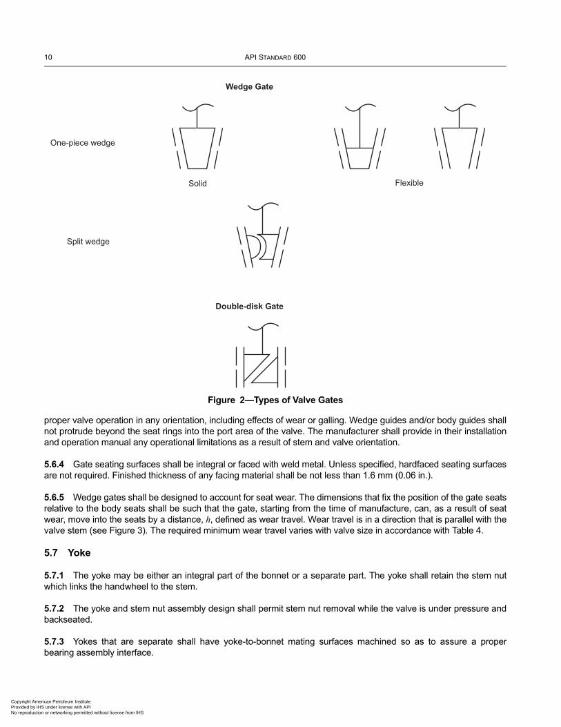
5.6.5 Wedge gates shall be designed to account for seat wear. The dimensions that fix the position of the gate seats relative to the body seats shall be such that the gate, starting from the time of manufacture, can, as a result of seat wear, move into the seats by a distance, h, defined as wear travel. Wear travel is in a direction that is parallel with the valve stem (see Figure 3). The required minimum wear travel varies with valve size in accordance with Table 4.
5.7 Yoke
5.7.1 The yoke may be either an integral part of the bonnet or a separate part. The yoke shall retain the stem nut which links the handwheel to the stem.
5.7.2 The yoke and stem nut assembly design shall permit stem nut removal while the valve is under pressure and backseated.
5.7.3 Yokes that are separate shall have yoke-to-bonnet mating surfaces machined so as to assure a proper bearing assembly interface.
Figure 2—Types of Valve Gates
Wedge Gate
FlexibleSolid
One-piece wedge
Split wedge
Double-disk Gate
erican Petroleum Institute IHS under license with API tion or networking permitted without license from IHS
STEEL GATE VALVES—FLANGED AND BUTT-WELDING ENDS, BOLTED BONNETS 11
Copyright AmericaProvided by IHS uNo reproduction o
5.7.4 The yoke-to-stem nut bearing surfaces shall be machined flat and parallel. A lubricating fitting shall be provided for the bearing surfaces.
5.8 Stem and Stem Nut
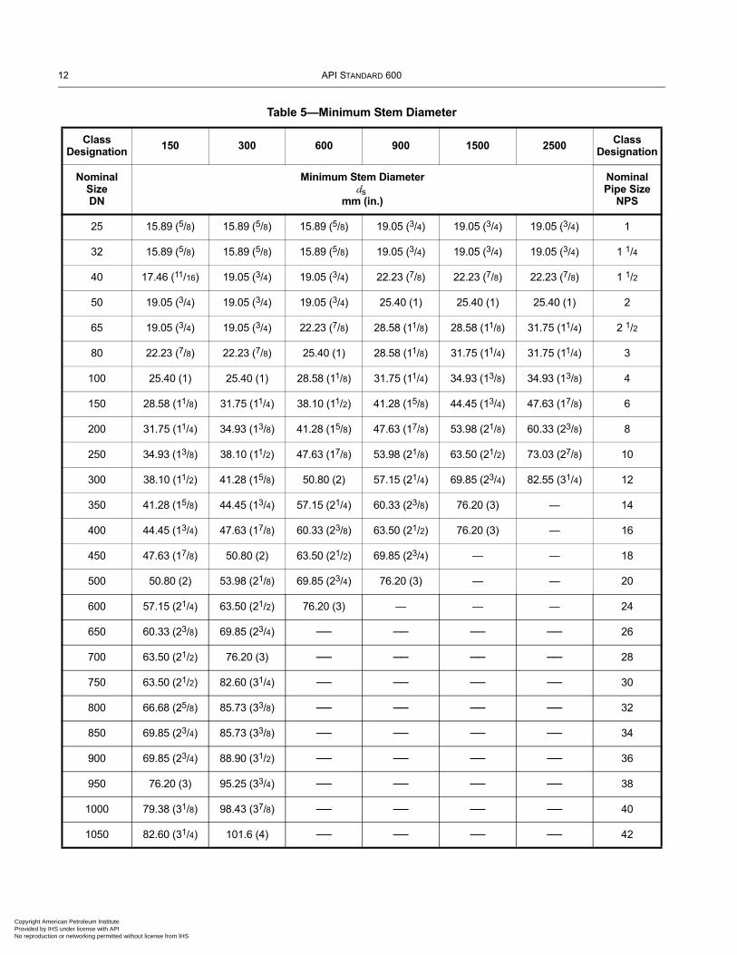
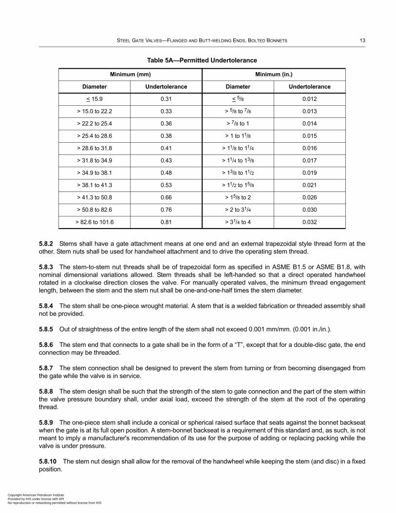
5.8.1 The minimum stem diameter, ds, shall be as given in Table 5. To allow the use of standard diameter round bars, an undertolerance is permitted in accordance with Table 5A. The minimum stem diameter applies to the stem along the surface area that comes into contact with the packing and to the major diameter of the trapezoidal stem thread. However, the major diameter of the stem thread may be reduced, at the manufacturer’s option, by no more than 1.6 mm (0.06 in.). The stem surface area in contact with the packing shall have a surface finish, Ra, of 0.80 µm (32 µin.) or smoother. The actual stem diameter shall take into account the valve design details and the stem material strength characteristics. Note that the stem strength shall be considered when calculating the maximum input force from the handwheel and gear box (if equipped) in accordance with MSS SP-91 or in accordance with maximum rim pull when specified by the Purchaser.
Figure 3—Wear Travel
Table 4—Minimum Wear Travel and Maximum Stem Projection
Valve Size Range, DN (NPS)
Wear Travel, hmm (in.)
Maximum Stem Projectionmm (in.)
DN ≤ 50 (NPS ≤ 2) 2.3 (0.09) 11.5 (0.45)
65 ≤ DN ≤ 150 (21/2 ≤ NPS ≤ 6) 3.3 (0.13) 16.5 (0.65)
200 ≤ DN ≤ 300 (8 ≤ NPS ≤ 12) 6.4 (0.25) 19.2 (0.75)
350 ≤ DN ≤ 450 (14 ≤ NPS ≤ 18) 9.7 (0.38) 29.1 (1.14)
500 ≤ DN ≤ 600 (20 ≤ NPS ≤ 24) 12.7 (0.50) 38.1 (1.50)
650 ≤ DN ≤ 700 (26 ≤ NPS ≤ 28) 16.0 (0.62) 48.0 (1.86)
750 ≤ DN ≤ 900 (30 ≤ NPS ≤ 36) 19.1 (0.75) 57.3 (2.25)
950 ≤ DN ≤ 1050 (38 ≤ NPS ≤ 42) 25.4 (1.00) 76.2 (3.00)
StemConnection
Gate seat position(new valve)
Weartravel
New Seats Worn Seats
Gate seat position (after wear)
Centerline of body seat face
n Petroleum Institute nder license with API r networking permitted without license from IHS
12 API STANDARD 600
Copyright AmProvided by No reproduc
Table 5—Minimum Stem Diameter
Class Designation
150 300 600 900 1500 2500 Class Designation
Nominal SizeDN
Minimum Stem Diameterds
mm (in.)
Nominal Pipe Size
NPS
25 15.89 (5/8) 15.89 (5/8) 15.89 (5/8) 19.05 (3/4) 19.05 (3/4) 19.05 (3/4) 1
32 15.89 (5/8) 15.89 (5/8) 15.89 (5/8) 19.05 (3/4) 19.05 (3/4) 19.05 (3/4) 1 1/4
40 17.46 (11/16) 19.05 (3/4) 19.05 (3/4) 22.23 (7/8) 22.23 (7/8) 22.23 (7/8) 1 1/2
50 19.05 (3/4) 19.05 (3/4) 19.05 (3/4) 25.40 (1) 25.40 (1) 25.40 (1) 2
65 19.05 (3/4) 19.05 (3/4) 22.23 (7/8) 28.58 (11/8) 28.58 (11/8) 31.75 (11/4) 2 1/2
80 22.23 (7/8) 22.23 (7/8) 25.40 (1) 28.58 (11/8) 31.75 (11/4) 31.75 (11/4) 3
100 25.40 (1) 25.40 (1) 28.58 (11/8) 31.75 (11/4) 34.93 (13/8) 34.93 (13/8) 4
150 28.58 (11/8) 31.75 (11/4) 38.10 (11/2) 41.28 (15/8) 44.45 (13/4) 47.63 (17/8) 6
200 31.75 (11/4) 34.93 (13/8) 41.28 (15/8) 47.63 (17/8) 53.98 (21/8) 60.33 (23/8) 8
250 34.93 (13/8) 38.10 (11/2) 47.63 (17/8) 53.98 (21/8) 63.50 (21/2) 73.03 (27/8) 10
300 38.10 (11/2) 41.28 (15/8) 50.80 (2) 57.15 (21/4) 69.85 (23/4) 82.55 (31/4) 12
350 41.28 (15/8) 44.45 (13/4) 57.15 (21/4) 60.33 (23/8) 76.20 (3) — 14
400 44.45 (13/4) 47.63 (17/8) 60.33 (23/8) 63.50 (21/2) 76.20 (3) — 16
450 47.63 (17/8) 50.80 (2) 63.50 (21/2) 69.85 (23/4) — — 18
500 50.80 (2) 53.98 (21/8) 69.85 (23/4) 76.20 (3) — — 20
600 57.15 (21/4) 63.50 (21/2) 76.20 (3) — — — 24
650 60.33 (23/8) 69.85 (23/4) ── ── ── ── 26
700 63.50 (21/2) 76.20 (3) ── ── ── ── 28
750 63.50 (21/2) 82.60 (31/4) ── ── ── ── 30
800 66.68 (25/8) 85.73 (33/8) ── ── ── ── 32
850 69.85 (23/4) 85.73 (33/8) ── ── ── ── 34
900 69.85 (23/4) 88.90 (31/2) ── ── ── ── 36
950 76.20 (3) 95.25 (33/4) ── ── ── ── 38
1000 79.38 (31/8) 98.43 (37/8) ── ── ── ── 40
1050 82.60 (31/4) 101.6 (4) ── ── ── ── 42
erican Petroleum Institute IHS under license with API tion or networking permitted without license from IHS
STEEL GATE VALVES—FLANGED AND BUTT-WELDING ENDS, BOLTED BONNETS 13
Copyright AmericaProvided by IHS uNo reproduction o
5.8.2 Stems shall have a gate attachment means at one end and an external trapezoidal style thread form at the other. Stem nuts shall be used for handwheel attachment and to drive the operating stem thread.
5.8.3 The stem-to-stem nut threads shall be of trapezoidal form as specified in ASME B1.5 or ASME B1.8, with nominal dimensional variations allowed. Stem threads shall be left-handed so that a direct operated handwheel rotated in a clockwise direction closes the valve. For manually operated valves, the minimum thread engagement length, between the stem and the stem nut shall be one-and-one-half times the stem diameter.
5.8.4 The stem shall be one-piece wrought material. A stem that is a welded fabrication or threaded assembly shall not be provided.
5.8.5 Out of straightness of the entire length of the stem shall not exceed 0.001 mm/mm. (0.001 in./in.).
5.8.6 The stem end that connects to a gate shall be in the form of a “T”, except that for a double-disc gate, the end connection may be threaded.
5.8.7 The stem connection shall be designed to prevent the stem from turning or from becoming disengaged from the gate while the valve is in service.
5.8.8 The stem design shall be such that the strength of the stem to gate connection and the part of the stem within the valve pressure boundary shall, under axial load, exceed the strength of the stem at the root of the operating thread.
5.8.9 The one-piece stem shall include a conical or spherical raised surface that seats against the bonnet backseat when the gate is at its full open position. A stem-bonnet backseat is a requirement of this standard and, as such, is not meant to imply a manufacturer's recommendation of its use for the purpose of adding or replacing packing while the valve is under pressure.
5.8.10 The stem nut design shall allow for the removal of the handwheel while keeping the stem (and disc) in a fixed position.
Table 5A—Permitted Undertolerance
Minimum (mm) Minimum (in.)
Diameter Undertolerance Diameter Undertolerance
< 15.9 0.31 < 5/8 0.012
> 15.0 to 22.2 0.33 > 5/8 to 7/8 0.013
> 22.2 to 25.4 0.36 > 7/8 to 1 0.014
> 25.4 to 28.6 0.38 > 1 to 11/8 0.015
> 28.6 to 31.8 0.41 > 11/8 to 11/4 0.016
> 31.8 to 34.9 0.43 > 11/4 to 13/8 0.017
> 34.9 to 38.1 0.48 > 13/8 to 11/2 0.019
> 38.1 to 41.3 0.53 > 11/2 to 15/8 0.021
> 41.3 to 50.8 0.66 > 15/8 to 2 0.026
> 50.8 to 82.6 0.76 > 2 to 31/4 0.030
> 82.6 to 101.6 0.81 > 31/4 to 4 0.032
n Petroleum Institute nder license with API r networking permitted without license from IHS
14 API STANDARD 600
Copyright AmProvided by No reproduc
5.8.11 The stem-nut-to-handwheel attachment shall be through a hexagonal interface, a round interface having a keyway or another means of equivalent strength.
5.8.12 When the stem nut is retained in the yoke by means of a threaded bushing, the bushing shall be secured in place using either a lock weld or a positive mechanical lock. Locking by simple metal upsetting such as peening or staking is not permitted.
5.8.13 The closed-position stem thread projection beyond the stem nut, on a new manual handwheel-operated valve, shall be based on the minimum wear travel values listed in Table 4. The minimum distance shall be equal to the manufacturer’s specified wear travel and the maximum as indicated in Table 4.
5.8.14 Valves DN ≥ 150 (NPS ≥ 6) with pressure class ≥ 600, shall be furnished with stem nuts having ball or roller bearings.
5.9 Packing and Packing Box
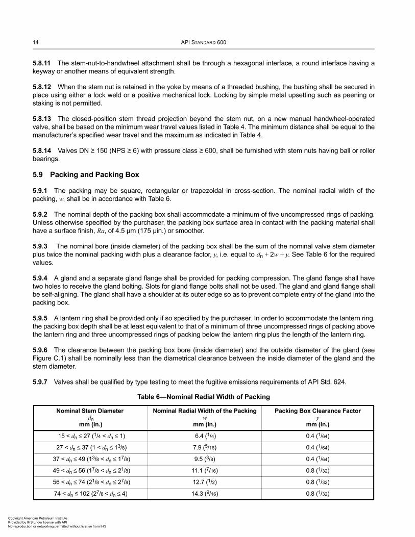
5.9.1 The packing may be square, rectangular or trapezoidal in cross-section. The nominal radial width of the packing, w, shall be in accordance with Table 6.
5.9.2 The nominal depth of the packing box shall accommodate a minimum of five uncompressed rings of packing. Unless otherwise specified by the purchaser, the packing box surface area in contact with the packing material shall have a surface finish, Ra, of 4.5 µm (175 µin.) or smoother.
5.9.3 The nominal bore (inside diameter) of the packing box shall be the sum of the nominal valve stem diameter plus twice the nominal packing width plus a clearance factor, y, i.e. equal to dn + 2w + y. See Table 6 for the required values.
5.9.4 A gland and a separate gland flange shall be provided for packing compression. The gland flange shall have two holes to receive the gland bolting. Slots for gland flange bolts shall not be used. The gland and gland flange shall be self-aligning. The gland shall have a shoulder at its outer edge so as to prevent complete entry of the gland into the packing box.
5.9.5 A lantern ring shall be provided only if so specified by the purchaser. In order to accommodate the lantern ring, the packing box depth shall be at least equivalent to that of a minimum of three uncompressed rings of packing above the lantern ring and three uncompressed rings of packing below the lantern ring plus the length of the lantern ring.
5.9.6 The clearance between the packing box bore (inside diameter) and the outside diameter of the gland (see Figure C.1) shall be nominally less than the diametrical clearance between the inside diameter of the gland and the stem diameter.
5.9.7 Valves shall be qualified by type testing to meet the fugitive emissions requirements of API Std. 624.
Table 6—Nominal Radial Width of Packing
Nominal Stem Diameter dn
mm (in.)
Nominal Radial Width of the Packingw
mm (in.)
Packing Box Clearance Factory
mm (in.)
15 < dn ≤ 27 (1/4 < dn ≤ 1) 6.4 (1/4) 0.4 (1/64)
27 < dn ≤ 37 (1 < dn ≤ 13/8) 7.9 (5/16) 0.4 (1/64)
37 < dn ≤ 49 (13/8 < dn ≤ 17/8) 9.5 (3/8) 0.4 (1/64)
49 < dn ≤ 56 (17/8 < dn ≤ 21/8) 11.1 (7/16) 0.8 (1/32)
56 < dn ≤ 74 (21/8 < dn ≤ 27/8) 12.7 (1/2) 0.8 (1/32)
74 < dn ≤ 102 (27/8 < dn ≤ 4) 14.3 (9/16) 0.8 (1/32)
erican Petroleum Institute IHS under license with API tion or networking permitted without license from IHS
STEEL GATE VALVES—FLANGED AND BUTT-WELDING ENDS, BOLTED BONNETS 15
Copyright AmericaProvided by IHS uNo reproduction o
5.10 Bolting
5.10.1 Bolting shall be standard inch series bolting, except if the purchaser specifies metric series bolting. Bolting for the bonnet-to-body joint shall be continuously threaded stud bolts with heavy, semi-finished hexagon nuts that are in accordance with ASME B18.2.2 or ASME B18.2.6M.
5.10.2 Yoke-to-bonnet bolting shall be either continuously threaded stud bolts or headed bolts with hexagon nuts.
5.10.3 Gland bolts shall be hinged eyebolts, headed bolts, stud bolts or studs. Hexagon nuts shall be used.
5.10.4 Bolting with diameters 25 mm (1 in.) and smaller shall have coarse (UNC) threads or the most nearly corresponding metric threads. Bolting with diameters larger than 25 mm (1 in.) shall be 8-thread series (8UN) or the most nearly corresponding metric threads. Bolt threads shall be Class 2A and nut threads shall be Class 2B, in accordance with ASME B1.1. Studs used for gland bolting shall use a Class 5 interference fit conforming to ASME B1.12. When metric bolting is used metric bolt threads shall be tolerance Class 6g and nuts tolerance Class 6H in accordance with ASME B1.13M.
5.11 Operation
5.11.1 Unless otherwise specified by the purchaser, the valve shall be supplied with a direct operated handwheel that opens the valve when turned in a counter-clockwise direction.
5.11.2 The handwheel shall be a spoke-rim type with a maximum of six spokes and shall be free from burrs and sharp edges. Unless otherwise specified, the handwheel shall be a one-piece casting or forging or a multi-piece carbon steel fabrication that includes other carbon steel product forms. Fabricated handwheels shall have strength and toughness characteristics comparable to that of handwheels made as one-piece castings or forgings.
5.11.3 The handwheel shall be marked with the word “OPEN” and an arrow pointing in the direction of opening, except when the handwheel size makes such marking impractical.
5.11.4 The handwheel shall be retained on the stem nut by a threaded handwheel nut.
5.11.5 If operation by a chain wheel, gearbox or power actuator is to be added to the valve, the purchaser shall specify the following, as applicable:
— for chainwheel operation, the dimension from the centerline of the valve stem or gear input shaft to the bottom of the chain loop;
— spur or bevel gear and the position of gearing handwheel relative to the pipe axis;
— electric, hydraulic, pneumatic or other actuator type;
— maximum service temperature and pressure differential across the valve disc;
— power supply attributes for power actuators.
5.11.6 Valve-to-gear-box or power actuator flange mating dimensions shall be according to ISO 5210 or MSS SP-102, or shall comply with the purchaser’s specifications.
5.12 Bypasses and Other Auxiliary Connections
Auxiliary connections to the body and/or bonnet, such as drains shall be furnished only if specified on the purchase order. The design and construction of the joint and the piping of auxiliary connections shall conform to the
n Petroleum Institute nder license with API r networking permitted without license from IHS
16 API STANDARD 600
Copyright AmProvided by No reproduc
requirements of ASME B16.34. When required for valve DN 50 (NPS 2) or larger, auxiliary connections shall be sized and located as specified in ASME B16.34. The size and location of auxiliary connections shall be indicated on the purchase order.
6 Materials
6.1 Materials Other Than Trim Materials
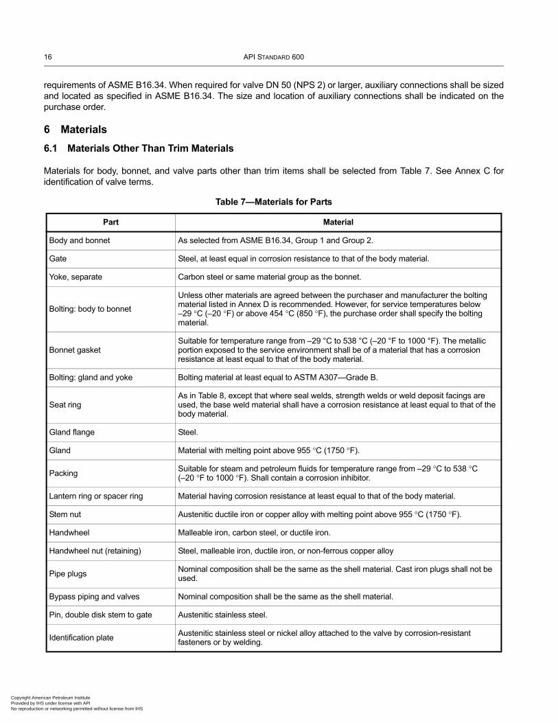
Materials for body, bonnet, and valve parts other than trim items shall be selected from Table 7. See Annex C for identification of valve terms.
Table 7—Materials for Parts
Part Material
Body and bonnet As selected from ASME B16.34, Group 1 and Group 2.
Gate Steel, at least equal in corrosion resistance to that of the body material.
Yoke, separate Carbon steel or same material group as the bonnet.
Bolting: body to bonnet
Unless other materials are agreed between the purchaser and manufacturer the bolting material listed in Annex D is recommended. However, for service temperatures below –29 °C (–20 °F) or above 454 °C (850 °F), the purchase order shall specify the bolting material.
Bonnet gasketSuitable for temperature range from –29 °C to 538 °C (–20 °F to 1000 °F). The metallic portion exposed to the service environment shall be of a material that has a corrosion resistance at least equal to that of the body material.
Bolting: gland and yoke Bolting material at least equal to ASTM A307—Grade B.
Seat ringAs in Table 8, except that where seal welds, strength welds or weld deposit facings are used, the base weld material shall have a corrosion resistance at least equal to that of the body material.
Gland flange Steel.
Gland Material with melting point above 955 °C (1750 °F).
PackingSuitable for steam and petroleum fluids for temperature range from –29 °C to 538 °C (–20 °F to 1000 °F). Shall contain a corrosion inhibitor.
Lantern ring or spacer ring Material having corrosion resistance at least equal to that of the body material.
Stem nut Austenitic ductile iron or copper alloy with melting point above 955 °C (1750 °F).
Handwheel Malleable iron, carbon steel, or ductile iron.
Handwheel nut (retaining) Steel, malleable iron, ductile iron, or non-ferrous copper alloy
Pipe plugs Nominal composition shall be the same as the shell material. Cast iron plugs shall not be used.
Bypass piping and valves Nominal composition shall be the same as the shell material.
Pin, double disk stem to gate Austenitic stainless steel.
Identification plate Austenitic stainless steel or nickel alloy attached to the valve by corrosion-resistant fasteners or by welding.
erican Petroleum Institute IHS under license with API tion or networking permitted without license from IHS
STEEL GATE VALVES—FLANGED AND BUTT-WELDING ENDS, BOLTED BONNETS 17
Copyright AmericaProvided by IHS uNo reproduction o
6.2 Trim
6.2.1 The trim is comprised of the following:
a) stem;
b) body seating surface;
c) gate seating surface;
d) bushing, or a deposited weld, for the backseat and stem hole guide;
e) small internal parts that normally contact the service fluid.
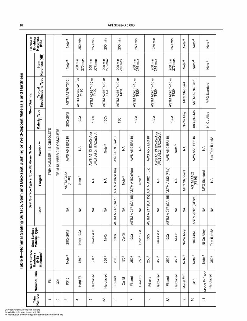
6.2.2 The trim material, except as stated in Items a) through d) below, shall be the manufacturer’s standard material for the type listed in Table 8 for the trim number specified in the purchase order. The typical specifications included in Table 8 represent some acceptable grades.
a) If a trim number listed in Table 8 is specified, then an alternative trim number as shown in Table 9 may be furnished.
b) If a single trim (e.g. trim 5) is furnished, both the seating surface of the body seat ring and the seating surface of the gate shall be made of the type of material shown in Table 8.
c) If a combination trim (e.g. trim 8) is furnished, the seating surface of the body seat ring shall be made of one of the two types of material shown in Table 8, and the seating surface of the gate shall be made of the other type of material shown.
d) The stem, backseat, stem hole guide and the small internal parts [see 6.2.1, Item e)] shall be of the type of material and hardness listed in Table 8. The stem shall be a wrought material.
e) The base material of the valve wedge/disc and separate body seat ring, when used, shall be of a nominal material composition equal to the body or to that of the stem material; except for wedge or disc material made of solid trim material.
7 Testing, Inspection and Examination
7.1 Inspection and Examination
7.1.1 The valve manufacturer shall examine each valve to assure compliance to this standard.
7.1.2 If inspection by the purchaser is specified in the purchase order, inspection shall be in accordance with API 598. Examination by the manufacturer shall be as specified in API 598.
7.2 Pressure Tests
Each valve shall be pressure tested as specified in API 598.
7.3 Repairs of Defects
Defects in the shell of a cast or forged, carbon or alloy steel valve that are revealed by inspection or testing shall be repaired as permitted by the most nearly applicable ASTM cast or forged material specification listed in ASME B16.34.
n Petroleum Institute nder license with API r networking permitted without license from IHS
18 API STANDARD 600
Copyright AmProvided by INo reproduct
Tab
le 8
—N
om
inal
Sea
tin
g S
urf
ace,
Ste
m a
nd
Bac
ksea
t B
ush
ing
or
Wel
d-d
epo
sit
Mat
eria
ls a
nd
Har
dn
ess
Trim
N
um
ber
No
min
al T
rim
Sea
t Su
rfac
e H
ard
nes
s (H
B)
Min
imu
ma
Sea
t S
urf
ace
Mat
eria
l Typ
e b
S
eat
Su
rfac
e Ty
pic
al S
pec
ific
atio
ns
Gra
de
Ste
m/B
ush
ing
B
acks
eat
Bu
shin
g
Har
dn
ess
(HB
)C
ast
Fo
rged
Wel
ded
mM
ater
ial T
ype
bTy
pic
al
Sp
ecif
icat
ion
s Ty
pe
Ste
m
Har
dn
ess
(HB
)
1F
6 T
RIM
NU
MB
ER
1 IS
OB
SO
LET
E
230
4T
RIM
NU
MB
ER
2 IS
OB
SO
LET
E
3F
310
Not
e d
25C
r-20
Ni
NA
AS
TM
A18
2 (F
310)
AW
S A
5.9
ER
310
25C
r-20
Ni
AS
TM
A27
6-T
310
Not
e d
Not
e d
4H
ard
F6
750
eH
ard
13C
rN
AN
ote
fN
A13
Cr
AS
TM
A27
6-T
410
or
T42
020
0 m
in
275
max
250
min
.
5H
ardf
aced
350
eC
o-C
r A
gN
AN
AA
WS
A5.
13 E
CoC
r-A
or
AW
S A
5.21
ER
CoC
r-A
13C
rA
ST
M A
276
T41
0 or
T
420
200
min
275
max
250
min
.
5A
Har
dfac
ed35
0 e
Ni-C
rN
AN
AN
ote
h13
Cr
AS
TM
A27
6 T
410
or
T42
020
0 m
in
275
max
250
min
.
6F
6 an
d
Cu-
Ni
250
i 13
Cr
AS
TM
A 2
17 (
CA
15)
A
ST
M A
182
(F6a
) A
WS
A5.
9 E
R41
0 13
Cr
AS
TM
A27
6 T
410
or
T42
0 20
0 m
in
275
max
25
0 m
in
175
iC
u-N
iN
AN
ote
kN
A
7F
6 an
d
Har
d F
6
250
i13
Cr
AS
TM
A 2
17 (
CA
15)
AS
TM
A18
2 (F
6a)
AW
S A
5.9
ER
410
13C
r A
ST
M A
276
T41
0 or
T
420
200
min
27
5 m
ax
250
min
. 75
0 i
Har
d 13
Cr
NA
Not
e f
NA
8F
6 an
d
Har
dfac
ed
250
i13
Cr
AS
TM
A 2
17 (
CA
15)
AS
TM
A18
2 (F
6a)
AW
S A
5.9
ER
410
13C
rA
ST
M A
276
T41
0 or
T
420
200
min
27
5 m
ax
250
min
350
iC
o-C
r A
gN
AN
AA
WS
A5.
13 E
CoC
r-A
or
AW
S A
5.21
ER
CoC
r-A
8A
F6
and
Har
dfac
ed
250
i13
Cr
AS
TM
A 2
17 (
CA
15)
AS
TM
A18
2 (F
6a)
AW
S A
5.9
ER
410
13C
r A
ST
M A
276
T41
0 or
T
420
200
min
27
5 m
ax25
0 m
in.
350
iN
i-Cr
NA
NA
Not
e h
9M
onel
TM
*N
ote
dN
i-Cu
Allo
yN
AM
FG
Sta
ndar
dN
AN
i-Cu
Allo
yM
FG
Sta
ndar
dN
ote
dN
ote
d
1031
6N
ote
d18
Cr-
8Ni
AS
TM
A35
1 (C
F8M
)A
ST
M A
182
(F31
6)A
WS
A5.
9 E
R31
618
Cr-
8Ni-M
oA
ST
M A
276-
T31
6N
ote
dN
ote
d
11M
onel
TM
* a
nd
Har
dfac
ed
Not
e d
Ni-C
u A
lloy
NA
MF
G S
tand
ard
NA
N
i-Cu
Allo
y M
FG
Sta
ndar
d N
ote
d N
ote
d 35
0 i
Trim
5 o
r 5A
NA
NA
See
Trim
5 o
r 5A
erican Petroleum Institute
HS under license with API ion or networking permitted without license from IHS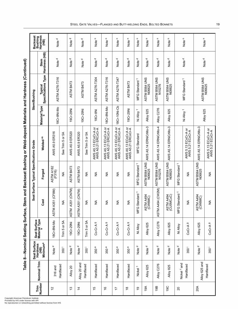
STEEL GATE VALVES—FLANGED AND BUTT-WELDING ENDS, BOLTED BONNETS 19
Copyright AmericaProvided by IHS uNo reproduction o
1231
6 an
d
Har
dfac
ed
Not
e d
18C
r-8N
i-Mo
AS
TM
A35
1 (C
F8M
)A
ST
M A
182
(F31
6)A
WS
A5.
9 E
R31
6 18
Cr-
8Ni-M
o A
ST
M A
276-
T31
6 N
ote
d N
ote
d
350
iT
rim 5
or
5AN
AN
AS
ee T
rim 5
or
5A
13A
lloy
20N
ote
d19
Cr-
29N
iA
ST
M A
351
(CN
7M)
AS
TM
B47
3A
WS
A5.
9 E
R32
019
Cr-
29N
iA
ST
M B
473
Not
e d
Not
e d
14A
lloy
20 a
nd
Har
dfac
ed
Not
e d
19C
r-29
Ni
AS
TM
A35
1 (C
N7M
) A
ST
M B
473
AW
S A
5.9
ER
320
19C
r-29
Ni
AS
TM
B47
3 N
ote
d N
ote
d 35
0 i
Trim
5 o
r 5A
NA
NA
See
Trim
5 o
r 5A
15H
ardf
aced
350
eC
o-C
r A
gN
AN
AA
WS
A5.
13 E
CoC
r-A
or
AW
S A
5.21
ER
CoC
r-A
18C
r-8N
iA
ST
M A
276-
T30
4N
ote
dN
ote
n
16H
ardf
aced
350
eC
o-C
r A
gN
AN
AA
WS
A5.
13 E
CoC
r-A
or
AW
S A
5.21
ER
CoC
r-A
18C
r-8N
i-Mo
AS
TM
A27
6-T
316
Not
e d
Not
e n
17H
ardf
aced
350
eC
o-C
r A
gN
AN
AA
WS
A5.
13 E
CoC
r-A
or
AW
S A
5.21
ER
CoC
r-A
18C
r-10
Ni-C
bA
ST
M A
276-
T34
7N
ote
dN
ote
n
18H
ardf
aced
350
eC
o-C
r A
gN
AN
AA
WS
A5.
13 E
CoC
r-A
or
AW
S A
5.21
ER
CoC
r-A
19C
r-29
Ni
AS
TM
B47
3N
ote
dN
ote
n
19N
icke
l 1N
ote
dN
i Allo
yM
FG
Sta
ndar
d 1
MF
G S
tand
ard
1M
FG
Sta
ndar
dN
i Allo
y 1
MF
G S
tand
ard
1N
ote
dN
ote
n
19A
Allo
y 62
5N
ote
dA
lloy
625
AS
TM
A49
4 (C
W6M
C)
AS
TM
B56
4 U
NS
N
0662
5A
WS
A5.
14 E
RN
iCrM
o-3
Allo
y 62
5A
ST
M B
564
UN
S
N06
625
Not
e d
Not
e n
19B
Allo
y C
276
Not
e d
Allo
y C
276
AS
TM
A49
4 (C
W2M
)A
ST
M B
564
UN
S
N10
276
AW
S A
5.14
ER
NiC
rMo-
4A
lloy
C27
6A
ST
M B
564
UN
S
N10
276
Not
e d
Not
e n
19C
Allo
y 82
5N
ote
dA
lloy
825
AS
TM
A49
4 (C
U5M
CuC
)A
ST
M B
564
UN
S
N08
825
AW
S A
5.14
ER
NiC
rMo-
3A
lloy
825
AS
TM
B56
4 U
NS
N
0882
5N
ote
dN
ote
n
20N
icke
l 1 a
nd
Har
dfac
ed
Not
e d
Ni A
lloy
MF
G S
tand
ard
1M
FG
Sta
ndar
d 1
Ni A
lloy
1M
FG
Sta
ndar
d 1
Not
e d
Not
e n
350
iC
oCr-
A g
NA
NA
AW
S 5
.13
EC
oCr-
A o
r A
WS
5.2
1 E
CoC
r-A
20A
Allo
y 62
5 an
d
Har
dfac
ed
Not
e d
Allo
y 62
5A
ST
M A
494
(CW
6MC
)A
ST
M B
564
UN
S
N06
625
AW
S A
5.14
ER
NiC
rMo-
3
Allo
y 62
5A
ST
M B
564
UN
S
N06
625
Not
e d
Not
e n
350
iC
oCr-
A g
NA
NA
AW
S 5
.13
EC
oCr-
A o
r A
WS
5.2
1 E
CoC
r-A
Tab
le 8
—N
om
inal
Sea
tin
g S
urf
ace,
Ste
m a
nd
Bac
ksea
t B
ush
ing
or
Wel
d-d
epo
sit
Mat
eria
ls a
nd
Har
dn
ess
(Co
nti
nu
ed)
Trim
N
um
ber
No
min
al T
rim
Sea
t Su
rfac
e H
ard
nes
s (H
B)
Min
imu
ma
Sea
t S
urf
ace
Mat
eria
l Typ
e b
S
eat
Su
rfac
e Ty
pic
al S
pec
ific
atio
ns
Gra
de
Ste
m/B
ush
ing
B
acks
eat
Bu
shin
g
Har
dn
ess
(HB
)C
ast
Fo
rged
Wel
ded
mM
ater
ial T
ype
bTy
pic
al
Sp
ecif
icat
ion
s Ty
pe
Ste
m
Har
dn
ess
(HB
)
n Petroleum Institute
nder license with API r networking permitted without license from IHS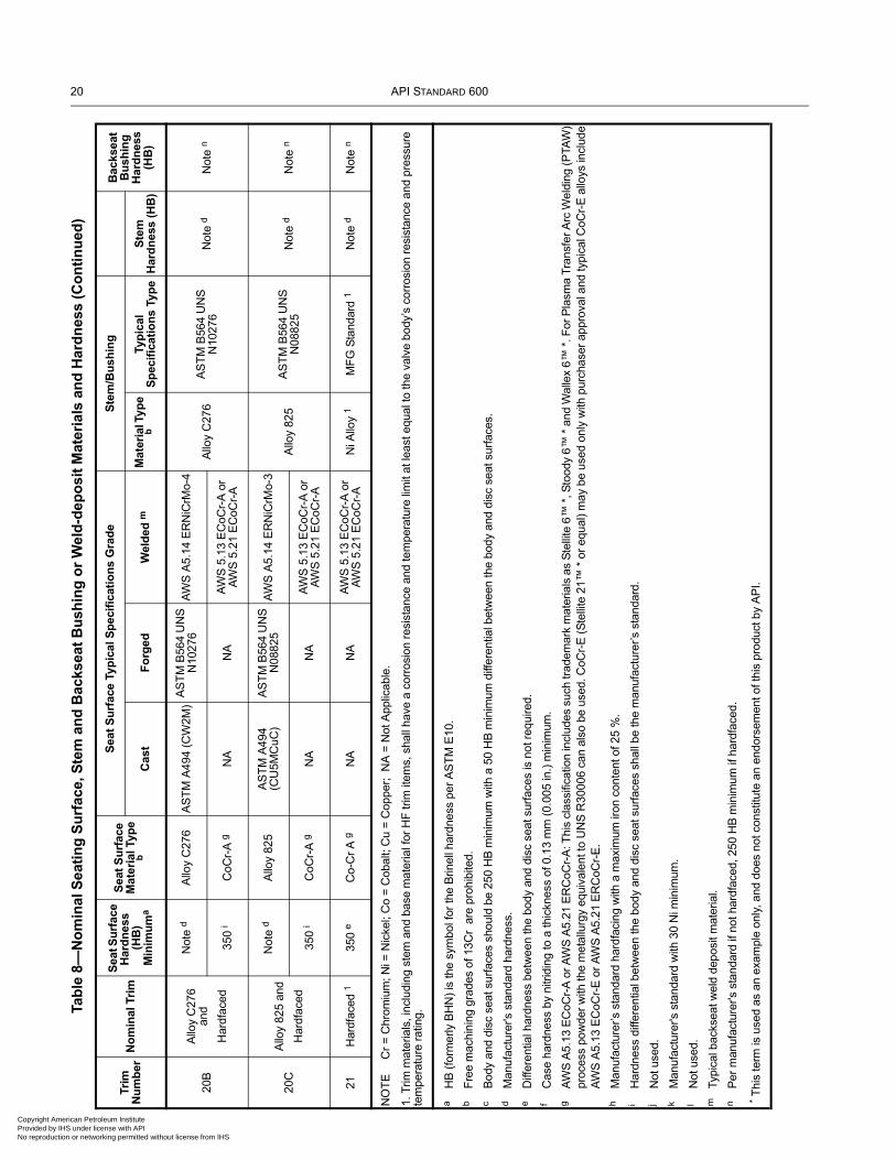
20 API STANDARD 600
Copyright AmProvided by INo reproduct
20B
Allo
y C
276
and
Har
dfac
ed
Not
e d
Allo
y C
276
AS
TM
A49
4 (C
W2M
)A
ST
M B
564
UN
S
N10
276
AW
S A
5.14
ER
NiC
rMo-
4
Allo
y C
276
AS
TM
B56
4 U
NS
N
1027
6N
ote
dN
ote
n
350
iC
oCr-
A g
NA
NA
AW
S 5
.13
EC
oCr-
A o
r A
WS
5.2
1 E
CoC
r-A
20C
Allo
y 82
5 an
d
Har
dfac
ed
Not
e d
Allo
y 82
5A
ST
M A
494
(CU
5MC
uC)
AS
TM
B56
4 U
NS
N
0882
5A
WS
A5.
14 E
RN
iCrM
o-3
Allo
y 82
5A
ST
M B
564
UN
S
N08
825
Not
e d
Not
e n
350
iC
oCr-
A g
NA
NA
AW
S 5
.13
EC
oCr-
A o
r A
WS
5.2
1 E
CoC
r-A
21H
ardf
aced
135
0 e
Co-
Cr
A g
NA
NA
AW
S 5
.13
EC
oCr-
A o
r A
WS
5.2
1 E
CoC
r-A
Ni A
lloy
1M
FG
Sta
ndar
d 1
Not
e d
Not
e n
NO
TE
C
r =
Chr
omiu
m; N
i = N
icke
l; C
o =
Cob
alt;
Cu
= C
oppe
r; N
A =
Not
App
licab
le.
1. T
rim m
ater
ials
, inc
ludi
ng s
tem
and
bas
e m
ater
ial f
or H
F tr
im it
ems,
sha
ll ha
ve a
cor
rosi
on r
esis
tanc
e an
d te
mpe
ratu
re li
mit
at le
ast e
qual
to th
e va
lve
body
’s c
orro
sion
res
ista
nce
and
pres
sure
te
mpe
ratu
re r
atin
g.
aH
B (
form
erly
BH
N)
is th
e sy
mbo
l for
the
Brin
ell h
ardn
ess
per
AS
TM
E10
.b
Fre
e m
achi
ning
gra
des
of 1
3Cr
are
pro
hibi
ted.
cB
ody
and
disc
sea
t sur
face
s sh
ould
be
250
HB
min
imum
with
a 5
0 H
B m
inim
um d
iffer
entia
l bet
wee
n th
e bo
dy a
nd d
isc
seat
sur
face
s.
dM
anuf
actu
rer's
sta
ndar
d ha
rdne
ss.
eD
iffer
entia
l har
dnes
s be
twee
n th
e bo
dy a
nd d
isc
seat
sur
face
s is
not
req
uire
d.f
Cas
e ha
rdne
ss b
y ni
trid
ing
to a
thic
knes
s of
0.1
3 m
m (
0.00
5 in
.) m
inim
um.
gA
WS
A5.
13 E
CoC
r-A
or
AW
S A
5.21
ER
CoC
r-A
: Thi
s cl
assi
ficat
ion
incl
udes
suc
h tr
adem
ark
mat
eria
ls a
s S
telli
te 6
™ *
, Sto
ody
6™ *
and
Wal
lex
6™ *
. For
Pla
sma
Tra
nsfe
r A
rc W
eldi
ng (
PTA
W)
proc
ess
pow
der
with
the
met
allu
rgy
equi
vale
nt to
UN
S R
3000
6 ca
n al
so b
e us
ed. C
oCr-
E (
Ste
llite
21™
* o
r eq
ual)
may
be
used
onl
y w
ith p
urch
aser
app
rova
l and
typi
cal C
oCr-
E a
lloys
incl
ude
AW
S A
5.13
EC
oCr-
E o
r A
WS
A5.
21 E
RC
oCr-
E.
hM
anuf
actu
rer’s
sta
ndar
d ha
rdfa
cing
with
a m
axim
um ir
on c
onte
nt o
f 25
%.
iH
ardn
ess
diffe
rent
ial b
etw
een
the
body
and
dis
c se
at s
urfa
ces
shal
l be
the
man
ufac
ture
r’s s
tand
ard.
jN
ot u
sed.
kM
anuf
actu
rer's
sta
ndar
d w
ith 3
0 N
i min
imum
.l
Not
use
d.m
Typi
cal b
acks
eat w
eld
depo
sit m
ater
ial.
nP
er m
anuf
actu
rer's
sta
ndar
d if
not h
ardf
aced
, 250
HB
min
imum
if h
ardf
aced
.
* T
his
term
is u
sed
as a
n ex
ampl
e on
ly, a
nd d
oes
not c
onst
itute
an
endo
rsem
ent o
f thi
s pr
oduc
t by
AP
I.
Tab
le 8
—N
om
inal
Sea
tin
g S
urf
ace,
Ste
m a
nd
Bac
ksea
t B
ush
ing
or
Wel
d-d
epo
sit
Mat
eria
ls a
nd
Har
dn
ess
(Co
nti
nu
ed)
Trim
N
um
ber
No
min
al T
rim
Sea
t Su
rfac
e H
ard
nes
s (H
B)
Min
imu
ma
Sea
t S
urf
ace
Mat
eria
l Typ
e b
S
eat
Su
rfac
e Ty
pic
al S
pec
ific
atio
ns
Gra
de
Ste
m/B
ush
ing
B
acks
eat
Bu
shin
g
Har
dn
ess
(HB
)C
ast
Fo
rged
Wel
ded
mM
ater
ial T
ype
bTy
pic
al
Sp
ecif
icat
ion
s Ty
pe
Ste
m
Har
dn
ess
(HB
)
erican Petroleum Institute
HS under license with API ion or networking permitted without license from IHS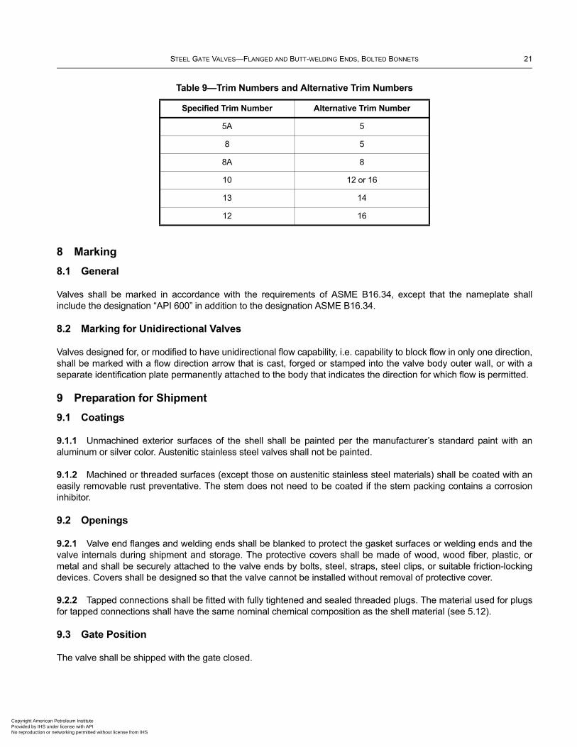
STEEL GATE VALVES—FLANGED AND BUTT-WELDING ENDS, BOLTED BONNETS 21
Copyright AmericaProvided by IHS uNo reproduction o
8 Marking
8.1 General
Valves shall be marked in accordance with the requirements of ASME B16.34, except that the nameplate shall include the designation “API 600” in addition to the designation ASME B16.34.
8.2 Marking for Unidirectional Valves
Valves designed for, or modified to have unidirectional flow capability, i.e. capability to block flow in only one direction, shall be marked with a flow direction arrow that is cast, forged or stamped into the valve body outer wall, or with a separate identification plate permanently attached to the body that indicates the direction for which flow is permitted.
9 Preparation for Shipment
9.1 Coatings
9.1.1 Unmachined exterior surfaces of the shell shall be painted per the manufacturer’s standard paint with an aluminum or silver color. Austenitic stainless steel valves shall not be painted.
9.1.2 Machined or threaded surfaces (except those on austenitic stainless steel materials) shall be coated with an easily removable rust preventative. The stem does not need to be coated if the stem packing contains a corrosion inhibitor.
9.2 Openings
9.2.1 Valve end flanges and welding ends shall be blanked to protect the gasket surfaces or welding ends and the valve internals during shipment and storage. The protective covers shall be made of wood, wood fiber, plastic, or metal and shall be securely attached to the valve ends by bolts, steel, straps, steel clips, or suitable friction-locking devices. Covers shall be designed so that the valve cannot be installed without removal of protective cover.
9.2.2 Tapped connections shall be fitted with fully tightened and sealed threaded plugs. The material used for plugs for tapped connections shall have the same nominal chemical composition as the shell material (see 5.12).
9.3 Gate Position
The valve shall be shipped with the gate closed.
Table 9—Trim Numbers and Alternative Trim Numbers
Specified Trim Number Alternative Trim Number
5A 5
8 5
8A 8
10 12 or 16
13 14
12 16
n Petroleum Institute nder license with API r networking permitted without license from IHS
22 API STANDARD 600
Copyright AmProvided by No reproduc
9.4 Stem Packing
The valve shall be shipped with the lantern ring, if specified, and the packing installed. The remaining adjustment length of the packing gland at the time of shipment, with the gland tight, shall be greater than one-and-one half times the packing width specified in Table 6.
9.5 Packaging
9.5.1 Unless export packaging is specified in the purchase order, valves may be shipped loose, palletized, or packed in a box or crate.
9.5.2 When export packaging is specified in the purchase order, valves shall be shipped individually or collectively in wooden boxes or crates in a manner that will prevent shifting within the package.
9.6 Purchase Order Information
Items marked with an asterisk in Annex B are considered an integral part of this standard, and shall be specified by the purchaser.
erican Petroleum Institute IHS under license with API tion or networking permitted without license from IHS
Copyright AmericaProvided by IHS uNo reproduction o
Annex A(informative)
API Monogram ProgramUse of the API Monogram by Licensees
A.1 Scope
A.1.1 Applicability
This annex is only normative for product supplied bearing the API Monogram and manufactured at a facility licensed by API; for all other instances it is not applicable.
A.1.2 General
The API Monogram® is a registered certification mark owned by the American Petroleum Institute (API) and authorized for licensing by the API Board of Directors. Through the API Monogram Program, API licenses product manufacturers to apply the API Monogram to products which comply with product specifications and have been manufactured under a quality management system that meets the requirements of API Q1. API maintains a complete, searchable list of all Monogram licensees on the API Composite List website (www.api.org/compositelist).
The application of the API Monogram and license number on products constitutes a representation and warranty by the licensee to API and to purchasers of the products that, as of the date indicated, the products were manufactured under a quality management system conforming to the requirements of API Q1 and that the product conforms in every detail with the applicable standard(s) or product specification(s). API Monogram program licenses are issued only after an on-site audit has verified that an organization has implemented and continually maintained a quality management system that meets the requirements of API Q1 and that the resulting products satisfy the requirements of the applicable API product specification(s) and/or standard(s). Although any manufacturer may claim that its products meet API product requirements without monogramming them, only manufacturers with a license from API can apply the API Monogram to their products.
Together with the requirements of the API Monogram license agreement, this annex establishes the requirements for those organizations who wish to voluntarily obtain an API license to provide API monogrammed products that satisfy the requirements of the applicable API product specification(s) and/or standard(s) and API Monogram Program requirements.
For information on becoming an API Monogram Licensee, please contact API, Certification Programs, 1220 L Street, N. W., Washington, DC 20005 or call 202-682-8145 or by email at [email protected].
A.2 Normative References
In addition to the referenced standards listed earlier in this document, this annex references the following standard:
API Specification Q1, Specification for Quality Management System Requirements for Manufacturing Organizations for the Petroleum and Natural Gas Industry
For Licensees under the Monogram Program, the latest version of this document shall be used. The requirements identified therein are mandatory.
23
n Petroleum Institute nder license with API r networking permitted without license from IHS
24 API STANDARD 600
Copyright AmProvided by No reproduc
A.3 API Monogram Program: Licensee Responsibilities
A.3.1 Monogram Program Requirements
For all organizations desiring to acquire and maintain a license to use the API Monogram, conformance with the following shall be required at all times:
a) the quality management system requirements of API Q1;
b) the API Monogram Program requirements of API Q1, Annex A;
c) the requirements contained in the API product specification(s) to which the organization is licensed;
d) the requirements contained in the API Monogram Program License Agreement.
A.3.2 Control of the Application and Removal of the API Monogram
Each licensee shall control the application and removal of the API Monogram in accordance with the following:
a) Products that do not conform to API specified requirements shall not bear the API Monogram.
b) Each licensee shall develop and maintain an API Monogram marking procedure that documents the marking/monogramming requirements specified by this annex and any applicable API product specification(s) and/or standard(s). The marking procedure shall:
1) define the authority responsible for application and removal of the API Monogram and license number;
2) define the method(s) used to apply the Monogram and license number;
3) identify the location on the product where the API Monogram and license number are to be applied;
4) require the application of the date of manufacture of the product in conjunction with the use of the API Monogram and license number;
5) require that the date of manufacture, at a minimum, be two digits representing the month and two digits representing the year (e.g. 05-12 for May 2012) unless otherwise stipulated in the applicable API product specification(s) or standard(s); and
6) define the application of all other required API product specification(s) and/or standard(s) marking requirements.
c) Only an API licensee shall apply the API Monogram and its designated license number to API monogrammable products.
d) The API Monogram and license number, when issued, are site-specific and subsequently the API Monogram shall only be applied at that site specific licensed facility location.
e) The API Monogram may be applied at any time appropriate during the production process but shall be removed in accordance with the licensee’s API Monogram marking procedure if the product is subsequently found to be out of conformance with any of the requirements of the applicable API product specification(s) and/or standard(s) and API Monogram Program.
erican Petroleum Institute IHS under license with API tion or networking permitted without license from IHS
STEEL GATE VALVES—FLANGED AND BUTT-WELDING ENDS, BOLTED BONNETS 25
Copyright AmericaProvided by IHS uNo reproduction o
For certain manufacturing processes or types of products, alternative API Monogram marking procedures may be acceptable. Requirements for alternative API Monogram marking are detailed in the, API Monogram Program Alternative Marking of Products License Agreement, available on the API Monogram Program website at http://www.api.org/alternative-marking.
A.3.3 Design and Design Documentation
Each licensee and/or applicant for licensing shall maintain current design documentation as identified in API Q1 for all of the applicable products that fall under the scope of each Monogram license. The design document information shall provide objective evidence that the product design meets the requirements of the applicable and most current API product specification(s) and/or standard(s). The design documentation shall be made available during API audits of the facility.
In specific instances, the exclusion of design activities is allowed under the Monogram Program, as detailed in Advisory # 6, available on API Monogram Program website at http://www.api.org/advisories.
A.3.4 Manufacturing Capability
The API Monogram Program is designed to identify facilities that have demonstrated the ability to manufacture equipment that conforms to API specifications and/or standards. API may refuse initial licensing or suspend current licensing based on a facility’s level of manufacturing capability. If API determines that an additional review is warranted, API may perform additional audits (at the organization’s expense) of any subcontractors to ensure their conformance with the requirements of the applicable API product specification(s) and/or standard(s).
A.3.5 Use of the API Monogram in Advertising
An API Monogram licensee shall not use the API Monogram and/or license number on letterheads, buildings or other structures, websites or in any advertising without an express statement of fact describing the scope of Licensee’s authorization (license number and product specification). The Licensee should contact API for guidance on the use of the API Monogram other than on products.
A.4 Product Marking Requirements
A.4.1 General
These marking requirements shall apply only to those API Licensees wishing to mark applicable products in conjunction with the requirements of the API Monogram Program.
A.4.2 Product Specification Identification
Manufacturers shall mark products as specified by the applicable API specifications or standards. Marking shall include reference to the applicable API specification and/or standard. Unless otherwise specified, reference to the API specifications and/or standards shall be, as a minimum, “API [Document Number]” (e.g. API 6A, or API 600). Unless otherwise specified, when space allows, the marking may include use of “Spec” or “Std”, as applicable (e.g. API Spec 6A or API Std 600).
A.4.3 Units
Products shall be marked with units as specified in the API specification and/or standard. If not specified, equipment shall be marked with U.S. customary (USC) units. Use of dual units [USC units and metric (SI) units] may be acceptable, if such units are allowed by the applicable product specification and/or standard.
n Petroleum Institute nder license with API r networking permitted without license from IHS
26 API STANDARD 600
Copyright AmProvided by No reproduc
A.4.4 Nameplates
Nameplates, when applicable, shall be made of a corrosion-resistant material unless otherwise specified by the API specification and/or standard. Nameplate shall be located as specified by the API specification and/or standard. If the location is not specified, then the licensee shall develop and maintain a procedure detailing the location to which the nameplate shall be applied. Nameplates may be attached at any time during the manufacturing process.
The API Monogram and license number shall be marked on the nameplate, in addition to the other product marking requirements specified by the applicable product specification and/or standard.
A.4.5 License Number
The API Monogram license number shall not be used unless it is marked in conjunction with the API Monogram. The license number shall be used in close proximity to the API Monogram.
A.5 API Monogram Program: Nonconformance Reporting
API solicits information on products that are found to be nonconforming with API specified requirements, as well as field failures (or malfunctions), which are judged to be caused by either specification and/or standard deficiencies or nonconformities against API specified requirements. Customers are requested to report to API all problems with API monogrammed products. A nonconformance may be reported using the API Nonconformance Reporting System available at http://compositelist.api.org/ncr.aspx.
erican Petroleum Institute IHS under license with API tion or networking permitted without license from IHS
Copyright AmericaProvided by IHS uNo reproduction o
Annex B(normative)
Information to be Specified by the Purchaser
1) Supplemental requirements of this standard shall be specifically stated in the purchase order.
2) If no supplemental requirements are to be taken to this standard, the purchase order just needs to refer to API 600 and to specify the items in the following list that are marked with an asterisk (*). The items listed below without an asterisk are options that may also be specified:
a) valve size *;
b) pressure class *;
c) flanged ends, including flange facing finish (for sizes over DN 600 (NPS 24) specify Series A or B); or welding ends, including bore *;
d) auxiliary connections and openings;
e) valve orientation;
f) additional hard facing of body and/or wedge guides;
g) bonnet gasket and/or bonnet flange facing;
h) tapped openings;
i) wedge gate or double-disc gate; also type of wedge, if required *;
j) lantern ring;
k) chainwheel and chain;
l) gear operation, including type and arrangement, and the design maximum pressure differential across the valve;
m) power operation, including type of power and power unit, and the design maximum pressure differential across the valve; frequency of operation;
n) bypass—specify either flanged or welded bonnet bypass valve;
o) material of the valve shell *;
p) nominal trim material *;
q) any required exceptions to manufacturer’s permissible options (e.g. NACE MR 0103);
r) handwheels;
s) safety shield;
t) chainwheel and safety cables, if furnished as original equipment;
27
n Petroleum Institute nder license with API r networking permitted without license from IHS
28 API STANDARD 600
Copyright AmProvided by No reproduc
u) alternate stem packing material;
v) bonnet bolting material;
w) inspection by purchaser;
x) high pressure closure test;
y) supplementary examination and testing;
z) export packaging;
aa) pressure seal bonnet;
ab) materials from ASME B 16.34 Group 3.
erican Petroleum Institute IHS under license with API tion or networking permitted without license from IHS
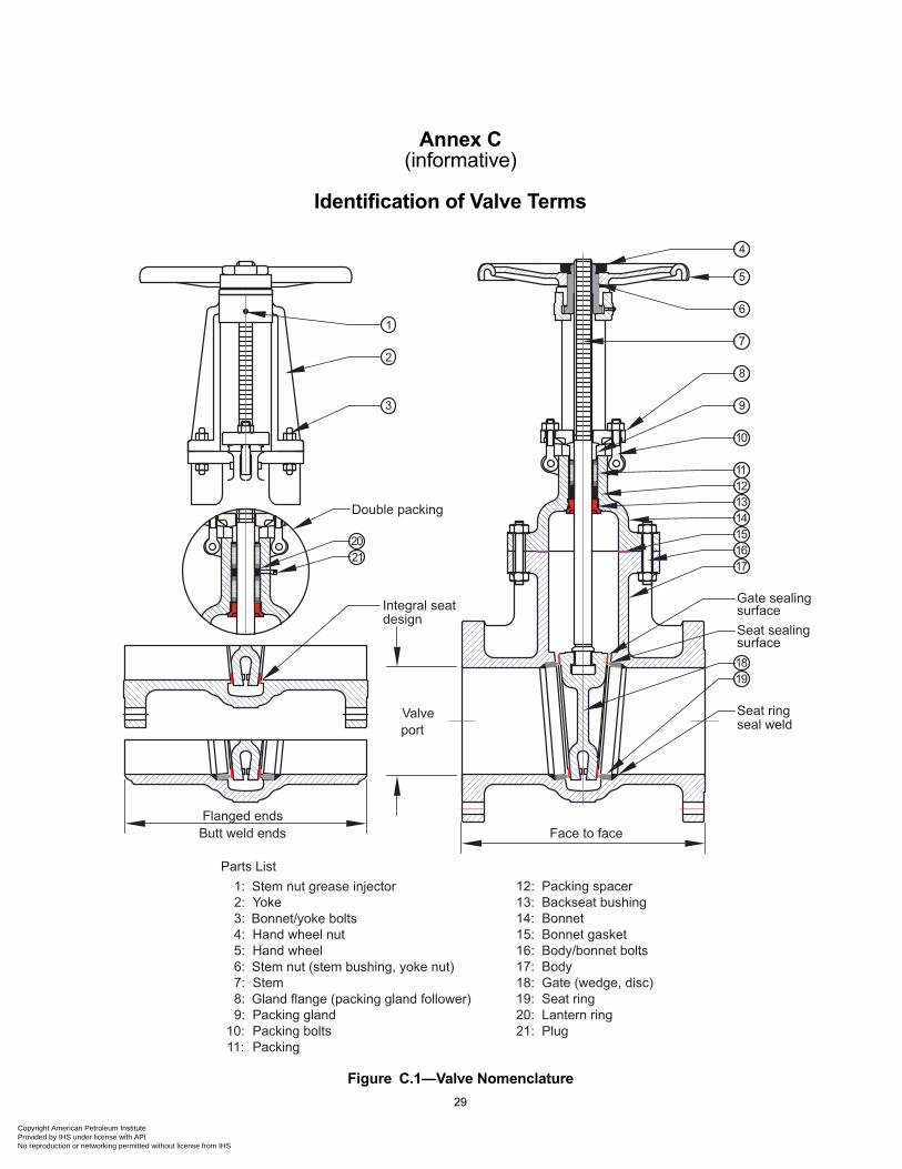
Copyright AmericaProvided by IHS uNo reproduction o
Annex C(informative)
Identification of Valve Terms
Figure C.1—Valve Nomenclature
Gate sealingsurfaceSeat sealingsurface
Seat ringseal weld
Integral seat design
Valveport
Face to faceFlanged ends
Gate (wedge, disc)
Hand wheel nut
Seat ring
Hand wheelStem nut (stem bushing, yoke nut)StemGland flange (packing gland follower)Packing glandPacking boltsPacking
Packing spacerBackseat bushingBonnetBonnet gasketBody/bonnet boltsBody
Bonnet/yoke boltsYokeStem nut grease injector
1
2
3
4
5
6
7
8
9
10
11121314151617
1819
1:2:3:4:5:6:7:8:9:
10:
13:14:15:16:17:18:19:20:
11:
12:Parts List
Double packing
20
Lantern ring
21
21: Plug
Butt weld ends
29
n Petroleum Institute nder license with API r networking permitted without license from IHS
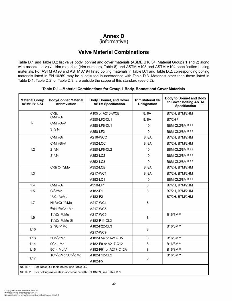
Copyright AProvided byNo reproduc
Annex D(informative)
Valve Material Combinations
Table D.1 and Table D.2 list valve body, bonnet and cover materials (ASME B16.34, Material Groups 1 and 2) along with associated valve trim materials (trim numbers, Table 8) and ASTM A193 and ASTM A194 specification bolting materials. For ASTM A193 and ASTM A194 listed bolting materials in Table D.1 and Table D.2, corresponding bolting materials listed in EN 10269 may be substituted in accordance with Table D.3. Materials other than those listed in Table D.1, Table D.2, or Table D.3, are outside the scope of this standard (see 6.2).
Table D.1—Material Combinations for Group 1 Body, Bonnet and Cover Materials
Material Group ASME B16.34
Body/Bonnet Material Abbreviation
Body, Bonnet, and Cover ASTM Specification
Trim Material CN Designation
Body to Bonnet and Body to Cover Bolting ASTM
Specification
1.1
C-Si, C-Mn-Si
C-Mn-Si-V
31/2 Ni
A105 or A216-WCB
A350-LF2-CL1
A350-LF6-CL1
A350-LF3
8, 8A
8, 8A
10
10
B7/2H, B7M/2HM
B7/2H b
B8M-CL2/8M b c d
B8M-CL2/8M b c d
1.2
C-Mn-Si
C-Mn-Si-V
21/2Ni
31/2Ni
A216-WCC
A352-LCC
A350-LF6-CL2
A352-LC2
A352-LC3
8, 8A
8, 8A
10
10
10
B7/2H, B7M/2HM
B7/2H, B7M/2HM
B8M-CL2/8M b c d
B8M-CL2/8M b c d
B8M-CL2/8M b c d
1.3
C-Si C-1/2Mo A352-LCB
A217-WC1
A352-LC1
8, 8A
8, 8A
10
B7/2H, B7M/2HM
B7/2H, B7M/2HM
B8M-CL2/8M b c d
1.4 C-Mn-Si A350-LF1 8 B7/2H, B7M/2HM
1.5 C-1/2Mo A182-F1 8 B7/2H, B7M/2HM
1.7
1/2Cr-1/2Mo
NI-1/2Cr-1/2Mo
3/4Ni-3/4Cr-1Mo
A182-F2
A217-WC4
A217-WC5
8
B7/2H, B7M/2HM
1.9 11/4Cr-1/2Mo
11/4Cr-1/2Mo-Si
A217-WC6
A182-F11-CL28
B16/8M e
1.10 21/4Cr-1Mo A182-F22-CL3
A217-WC9 8
B16/8M e
1.13 5Cr-1/2Mo A182-F5a or A217-C5 8 B16/8M e
1.14 9Cr-1 Mo A182-F9 or A217-C12 8 B16/8M e
1.15 9Cr-1Mo-V A182-F91 or A217-C12A 8 B16/8M e
1.171Cr-1/2Mo 5Cr-1/2Mo A182-F12-CL2
A182-F5 8
B16/8M e
NOTE 1 For Table D.1 table notes, see Table D.2.
NOTE 2 For bolting materials in accordance with EN 10269, see Table D.3.
30
merican Petroleum Institute IHS under license with API tion or networking permitted without license from IHS
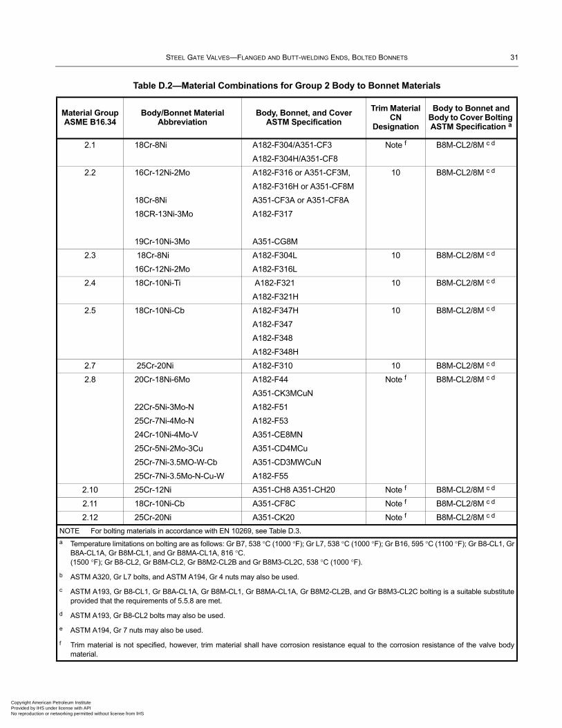
STEEL GATE VALVES—FLANGED AND BUTT-WELDING ENDS, BOLTED BONNETS 31
Copyright AmericaProvided by IHS uNo reproduction o
Table D.2—Material Combinations for Group 2 Body to Bonnet Materials
Material Group ASME B16.34
Body/Bonnet Material Abbreviation
Body, Bonnet, and Cover ASTM Specification
Trim Material CN
Designation
Body to Bonnet and Body to Cover Bolting ASTM Specification a
2.1 18Cr-8Ni A182-F304/A351-CF3
A182-F304H/A351-CF8
Note f B8M-CL2/8M c d
2.2 16Cr-12Ni-2Mo
18Cr-8Ni
18CR-13Ni-3Mo
19Cr-10Ni-3Mo
A182-F316 or A351-CF3M,
A182-F316H or A351-CF8M
A351-CF3A or A351-CF8A
A182-F317
A351-CG8M
10 B8M-CL2/8M c d
2.3 18Cr-8Ni
16Cr-12Ni-2Mo
A182-F304L
A182-F316L
10 B8M-CL2/8M c d
2.4 18Cr-10Ni-Ti A182-F321
A182-F321H
10 B8M-CL2/8M c d
2.5 18Cr-10Ni-Cb A182-F347H
A182-F347
A182-F348
A182-F348H
10 B8M-CL2/8M c d
2.7 25Cr-20Ni A182-F310 10 B8M-CL2/8M c d
2.8 20Cr-18Ni-6Mo
22Cr-5Ni-3Mo-N
25Cr-7Ni-4Mo-N
24Cr-10Ni-4Mo-V
25Cr-5Ni-2Mo-3Cu
25Cr-7Ni-3.5MO-W-Cb
25Cr-7Ni-3.5Mo-N-Cu-W
A182-F44
A351-CK3MCuN
A182-F51
A182-F53
A351-CE8MN
A351-CD4MCu
A351-CD3MWCuN
A182-F55
Note f B8M-CL2/8M c d
2.10 25Cr-12Ni A351-CH8 A351-CH20 Note f B8M-CL2/8M c d
2.11 18Cr-10Ni-Cb A351-CF8C Note f B8M-CL2/8M c d
2.12 25Cr-20Ni A351-CK20 Note f B8M-CL2/8M c d
NOTE For bolting materials in accordance with EN 10269, see Table D.3.
a Temperature limitations on bolting are as follows: Gr B7, 538 °C (1000 °F); Gr L7, 538 °C (1000 °F); Gr B16, 595 °C (1100 °F); Gr B8-CL1, Gr B8A-CL1A, Gr B8M-CL1, and Gr B8MA-CL1A, 816 °C. (1500 °F); Gr B8-CL2, Gr B8M-CL2, Gr B8M2-CL2B and Gr B8M3-CL2C, 538 °C (1000 °F).
b ASTM A320, Gr L7 bolts, and ASTM A194, Gr 4 nuts may also be used.
c ASTM A193, Gr B8-CL1, Gr B8A-CL1A, Gr B8M-CL1, Gr B8MA-CL1A, Gr B8M2-CL2B, and Gr B8M3-CL2C bolting is a suitable substitute provided that the requirements of 5.5.8 are met.
d ASTM A193, Gr B8-CL2 bolts may also be used.
e ASTM A194, Gr 7 nuts may also be used.
f Trim material is not specified, however, trim material shall have corrosion resistance equal to the corrosion resistance of the valve body material.
n Petroleum Institute nder license with API r networking permitted without license from IHS
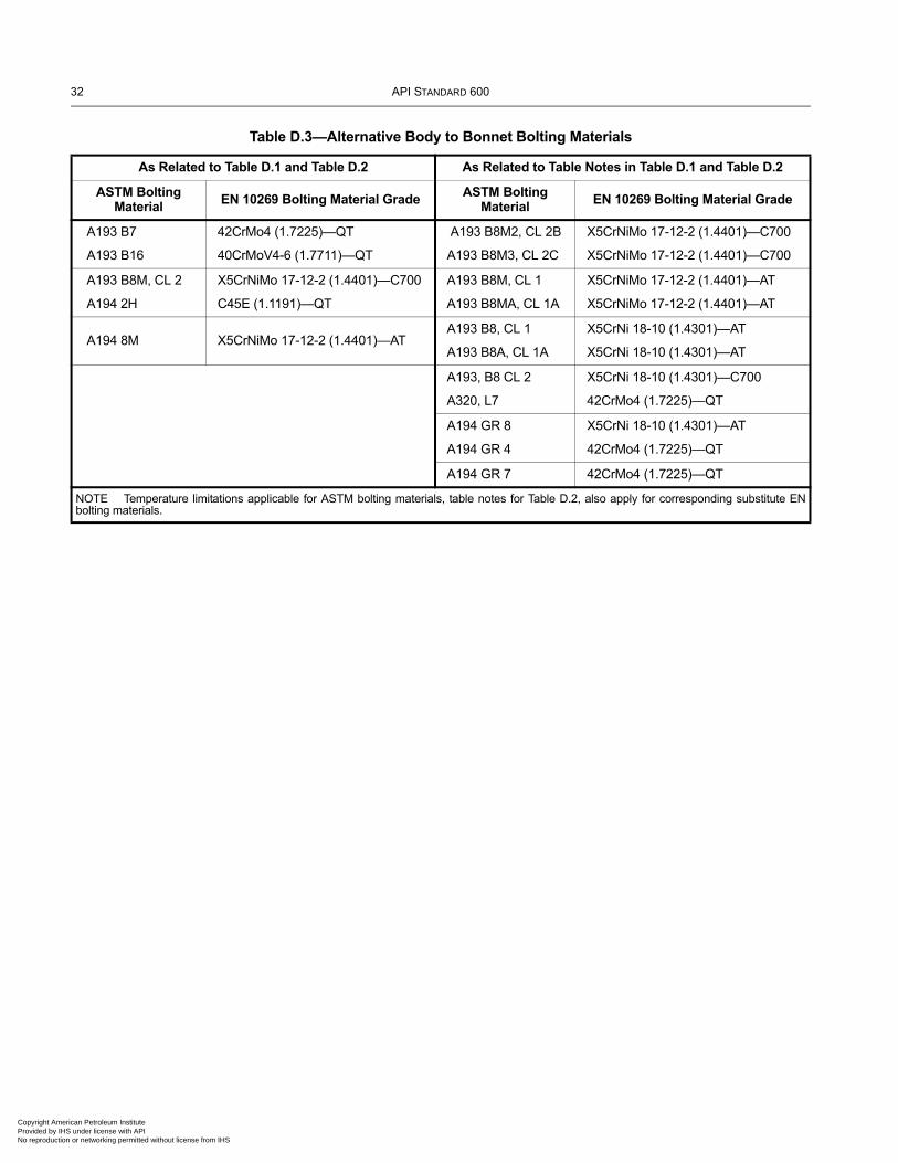
32 API STANDARD 600
Copyright AmProvided by No reproduc
Table D.3—Alternative Body to Bonnet Bolting Materials
As Related to Table D.1 and Table D.2 As Related to Table Notes in Table D.1 and Table D.2
ASTM Bolting Material
EN 10269 Bolting Material Grade ASTM Bolting Material
EN 10269 Bolting Material Grade
A193 B7
A193 B16
42CrMo4 (1.7225)—QT
40CrMoV4-6 (1.7711)—QT
A193 B8M2, CL 2B
A193 B8M3, CL 2C
X5CrNiMo 17-12-2 (1.4401)—C700
X5CrNiMo 17-12-2 (1.4401)—C700
A193 B8M, CL 2
A194 2H
X5CrNiMo 17-12-2 (1.4401)—C700
C45E (1.1191)—QT
A193 B8M, CL 1
A193 B8MA, CL 1A
X5CrNiMo 17-12-2 (1.4401)—AT
X5CrNiMo 17-12-2 (1.4401)—AT
A194 8M X5CrNiMo 17-12-2 (1.4401)—ATA193 B8, CL 1
A193 B8A, CL 1A
X5CrNi 18-10 (1.4301)—AT
X5CrNi 18-10 (1.4301)—AT
A193, B8 CL 2
A320, L7
X5CrNi 18-10 (1.4301)—C700
42CrMo4 (1.7225)—QT
A194 GR 8
A194 GR 4
X5CrNi 18-10 (1.4301)—AT
42CrMo4 (1.7225)—QT
A194 GR 7 42CrMo4 (1.7225)—QT
NOTE Temperature limitations applicable for ASTM bolting materials, table notes for Table D.2, also apply for corresponding substitute EN bolting materials.
erican Petroleum Institute IHS under license with API tion or networking permitted without license from IHS
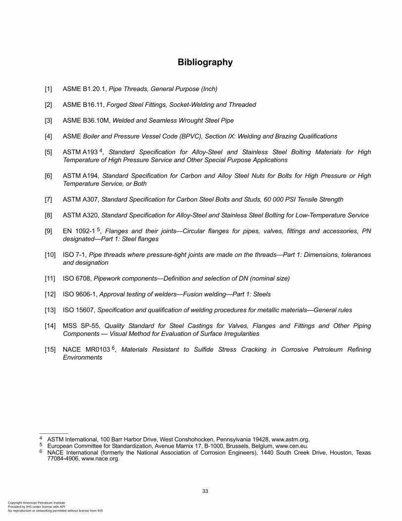
Copyright AmericaProvided by IHS uNo reproduction o
Bibliography
[1] ASME B1.20.1, Pipe Threads, General Purpose (Inch)
[2] ASME B16.11, Forged Steel Fittings, Socket-Welding and Threaded
[3] ASME B36.10M, Welded and Seamless Wrought Steel Pipe
[4] ASME Boiler and Pressure Vessel Code (BPVC), Section IX: Welding and Brazing Qualifications
[5] ASTM A193 4, Standard Specification for Alloy-Steel and Stainless Steel Bolting Materials for High Temperature of High Pressure Service and Other Special Purpose Applications
[6] ASTM A194, Standard Specification for Carbon and Alloy Steel Nuts for Bolts for High Pressure or High Temperature Service, or Both
[7] ASTM A307, Standard Specification for Carbon Steel Bolts and Studs, 60 000 PSI Tensile Strength
[8] ASTM A320, Standard Specification for Alloy-Steel and Stainless Steel Bolting for Low-Temperature Service
[9] EN 1092-1 5, Flanges and their joints—Circular flanges for pipes, valves, fittings and accessories, PN designated—Part 1: Steel flanges
[10] ISO 7-1, Pipe threads where pressure-tight joints are made on the threads—Part 1: Dimensions, tolerances and designation
[11] ISO 6708, Pipework components—Definition and selection of DN (nominal size)
[12] ISO 9606-1, Approval testing of welders—Fusion welding—Part 1: Steels
[13] ISO 15607, Specification and qualification of welding procedures for metallic materials—General rules
[14] MSS SP-55, Quality Standard for Steel Castings for Valves, Flanges and Fittings and Other Piping Components — Visual Method for Evaluation of Surface Irregularities
[15] NACE MR0103 6, Materials Resistant to Sulfide Stress Cracking in Corrosive Petroleum Refining Environments
4 ASTM International, 100 Barr Harbor Drive, West Conshohocken, Pennsylvania 19428, www.astm.org.5 European Committee for Standardization, Avenue Marnix 17, B-1000, Brussels, Belgium, www.cen.eu.6 NACE International (formerly the National Association of Corrosion Engineers), 1440 South Creek Drive, Houston, Texas
77084-4906, www.nace.org.
33
n Petroleum Institute nder license with API r networking permitted without license from IHS

Copyright American Petroleum Institute Provided by IHS under license with API No reproduction or networking permitted without license from IHS

Copyright American Petroleum Institute Provided by IHS under license with API No reproduction or networking permitted without license from IHS
Product No. C60013
Copyright American Petroleum Institute Provided by IHS under license with API No reproduction or networking permitted without license from IHS