steel cutting using abrasive water jet - llutf.llu.lv/conference/proceedings2017/papers/n014.pdf ·...
TRANSCRIPT

ENGINEERING FOR RURAL DEVELOPMENT Jelgava, 24.-26.05.2017.
75
STEEL CUTTING USING ABRASIVE WATER JET
Milan Brozek
Czech University of Life Sciences Prague [email protected]
Abstract. Technology of material parting using water of high pressure is considered as a modern and perspective method. It makes parting of practically all non-metallic as well as metallic materials possible. According to the type, properties and thickness of the parted material two methods are used, namely (pure) water jet machining and abrasive water jet machining. This article contains the machining test results of steel sheets of different thickness (5 to 20 mm) at different machining parameters. On the tests the influences of the machining speed (10 to 425 mm·min-1) and of the abrasive amount (211.5 to 417.8 g·min-1) on the cut width were observed. The cut was observed primarily at the water jet input and output. The deviation from the perpendicular line was observed, too. It was proved that the machining speed influences primarily the cut width and the deviation from the perpendicular line. The abrasive amount is of lesser importance. Kerf width ranges from about 1.05 to 1.15 mm (for a plate thickness of 5 mm, inlet of the water jet), from 0.25 to 0.70 mm (5 mm, outlet), from 1.10 to 1.35 mm (20 mm, inlet), and from 0.20 to 1.25 mm (20 mm, outlet). Deviation from the perpendicular line of cutting surfaces ranges from 2.35 to 4.65° (for a plate thickness of 5 mm) and from 0.15 to 1.35º (20 mm).
Keywords: abrasive water jet cutting, cutting, garnet, kerf width, kerf surface.
Introduction
The technology of metal parting using water has been known already for many years. But only in the second half of the 20th century it has managed to make devices, which have enabled industrial cutting, at first of non-metallic, later also of metallic materials. The first use of this method has been cutting of ceramic insulating materials of space shuttles at Boeing in 1974 [1]. The cutting technology using water has two modifications, namely:
• pure water jet machining (PWJM) – cutting using water without abrasive; • abrasive water jet machining (AWJM) – cutting using water jet with abrasive.
The majority of in practice used materials can be cut using water jet. Without problems it is possible to cut ferrous as well as non-ferrous metals, wood, plywood, stone, files, glass, mirror, paper, rubber, plastics, carpets, skin, composites etc. Hard glass or materials reacting sharply with water are some of exceptions [2-4]. Waterjet technology extends the range of currently used methods, e.g. laser cutting, plasma cutting or electro-erosive cutting.
At the water jet cutting of metallic materials it is possible to use relatively high cutting speeds, especially at materials of low thickness. In [5] the test results of the alloy AlMg3 of 3 mm thickness at cutting speeds up to 2000 mm·min-1 and of the steel 11 373 according to CSN 41 1373 of 3 mm thickness at the cutting speed up to 700 mm·min-1 are published. The cutting was carried out using the garnet abrasive of the amount 400 g·min-1 and the pressure of 4000 Bar. The device was not specified. With the increasing thickness of the cut material the maximum usable cutting speed sharply decreases.
Components made by cutting using abrasive waterjet machining are today used in all branches of the human activity. We find them, e.g. in engineering, transport, power engineering, industry, agriculture, food industry, architecture etc. [6-8]. Just as other methods of material parting the abrasive waterjet machining has advantages and disadvantages.
Advantages:
• the method is universal, it is possible to cut metallic as well as non-metallic materials, including hard-worked materials, explosive materials etc.;
• at cutting the basic material is not thermally or chemically influenced; • the jet acts on the material relatively small, therefore it is possible to cut brittle materials, e.g.
glass, ceramics, plastics etc.; • the kerf is relatively minimal – the kerf width is at the pure water jet up to about 0.4 mm, at
the abrasive water jet up to about 2 mm; • it is possible to cut in shape complicated products, often more layers altogether, with small
tolerances for dimensions and shape;
DOI: 10.22616/ERDev2017.16.N014

ENGINEERING FOR RURAL DEVELOPMENT Jelgava, 24.-26.05.2017.
76
• using water it is possible to cut materials dividable with problems, e.g. insulating materials, laminates, fibrocement etc.;
• it is possible to cut biological materials and food staffs, e.g. bones, meat, cheese, fruit, vegetable etc.;
• from one source (pump) it is possible to supply several jet heads; • green benefit – water jet cutting does not contaminate the environment, used water and
abrasive are recyclable.
Disadvantages:
• the method cannot be used for materials which can be by water damaged; • at some materials danger of corrosion; • danger of layer separation at multi-layer materials, e.g. at cutting of composites, sandwiches,
materials with enameled, metal plated or painted surface etc.; • lower productivity at cutting metallic materials of higher thickness; • necessity of leaving water jet energy dampening, which means more complicated fastening of
the cut material; • relatively high initial costs; • necessity of qualified attendance; • danger of accident [9-11].
At the cut surface quality evaluation made using the abrasive water jet the grades from Q5 to Q1 are usually used, when Q5 is of the highest, Q1 of the lowest quality. The grades are verbally evaluated as follows: Q5 excellent edge finish, Q4 good edge finish, Q3 clean cut, Q2 through cut and Q1 separation cut. But this classification is only qualitative and it depends on the consideration of every man. Therefore, it is necessary to consider it as of orientation. In this criterion no numerical parameters are defined and firms using this technology determine the cut quality by their own tests. Most often the visual evaluation is used, when the cut surface is compared with the surface of the firm specimen (etalon) [1; 2].
Material and methods
The cutting of the test specimens was carried out using the CNC cutting machine with the water jet technology AW-CT 0806 TKX delivered by the firm AWAC, cutting systems, Czech Republic. The dimensions of the table working area are 800 x 600 mm. The maximal cutting speed is 1000 mm·min-1. The table is connected with the catcher of the water jet remaining energy. The control system is AW-CT 1515 TKX. The input of the high pressure pump AccuStream A-6030 is 22 kW, the working pressure is 500 to 3800 Bar, maximum 4140 Bar.The machine has one cutting head A2 for the water jet machining and for the abrasive water jet machining. The batcher makes possible the batching of abrasive from 0 to 500 g·min-1. The abrasive AW-ADS 160 is conveyed by the pressure from the hopper to the cutting head. The hopper can contain 400 kg of abrasive. The part of the device is the compressor KAESER Aircenter SM9 and the compressed-air pump Versa Matic.
For the tests the cuboid specimens of dimensions 80 x 120 mm and thickness 5, 10, 15 and 20 mm from the steel 11 523 according to CSN 41 1523 were prepared. The equivalent steels are S355J2G3, St 62-3 or 1.0570. Its table chemical composition is as follows: C max = 0.20%, Mn max = 1.60 %, Si max = 0.55 %, P max = 0.040 % and S max = 0.045 %.The shape and dimensions of the test specimen are presented in Fig. 1.From each of the above mentioned thicknesses three test specimens were prepared and later cut using different amount of the abrasive mass flow rate, namely 211.5 g·min-1, 301.5 g·min-1 and 417.8 g·min-1.The used abrasive material was Garnet of the particle granulation 80 MESH. It is the same material as which is commonly used for the surface blasting, e.g. before adhesive bonding, surfacing or surface protection application [12-19]. The used abrasive is the waste, but it is possible to recycle it (system RAMS, recycling abrasive maximum saving) and to use again. At our department the use of the used abrasive for the composites production was tested (without success).

ENGINEERING FOR RURAL DEVELOPMENT Jelgava, 24.-26.05.2017.
77
On each of the test specimens ten cuts were made at different cutting speeds (Tab. 1). Later only such parameters were used, when the material was cut in the whole cross section. These parameters were determined by the preliminary tests.
Fig. 1.Shape and dimensions of the test specimen
Table 1 Cutting speed v (mm·min
-1)
Sheet thickness, mm v1 v2 v3 v4 v5 v6 v7 v8 v9 v10
5 50 100 150 200 250 300 350 375 400 425 10 40 60 80 100 120 140 160 180 200 220 15 20 40 60 80 90 100 110 120 130 140 20 10 20 30 40 50 60 70 80 90 100
The aim of the carried out tests was to assess the influence of the cutting speed, abrasive amount and material thickness on the kerf width and on the deviation of the cut surface from the cut axis.
For the evaluation of the test specimens the stereoscopic microscope SZP 11-T ZOOM with the digital CMOS camera connected to PC equipped with Quick Photo Industrial program was used. This set makes possible easy and relatively prompt measuring of lengths and angles.
On the upper surface of the test specimen (inlet of the water jet) are kerfs, irrespective on the cutting speed, quite similar and at first sight fundamental difference is not visible (Fig. 2a). But on the lower surface (outlet of the water jet) the differences are significant (Fig. 2b). The kerf appearance at the given material thickness depends primarily on the cutting speed, less on the used abrasive amount. The kerf downwards decreases in width and it is in the shape of the letter “V”.
At the look on the cut surface (Fig 3) it is evident that in the upper part the water jet has sufficient energy, it penetrates easily through the material and the cut surface is relatively smooth. But its energy gradually decreases, its bending occurs and on the surface unevennesses (wrinkles) occur, which downwards increase. This depends on the cutting parameters (primarily on the cutting speed and abrasive amount) and on the sort and thickness of the cut material.
The aim of the carried out tests was to evaluate the influence of the following parameters on the cut width:
• cutting speed (10 to 425 mm·min-1); • abrasive amount (211.5 to 417.8 g·min-1); • material thickness (steel; 5 mm, 10 mm, 15 mm and 20 mm)
It is supposable that the better cut can be obtained using lower cutting speed, more abrasive amount and lower material thickness.
Results and discussion
The results of the carried out tests are evident from Fig. 2 and from Figs. 4 to 7. With regard to the limited range of the article only selected results of specimens of 5 and 20 mm thickness are published.In Figs. 4to 7 the standard deviation is demonstrated by the line segments.

ENGINEERING FOR RURAL DEVELOPMENT Jelgava, 24.-26.05.2017.
78
a)
b)
Fig. 2. View on the test specimen from above: a – inlet of the water jet; b – outlet of the water jet
Fig. 3. Presentation of the cut surface (steel 11 523, thickness 50 mm, v = 20 mm·min-1
, abrasive
amount 211.5 g·min-1
, abrasive garnet MESH 80)
5 mm - inlet and outlet
0,0
0,2
0,4
0,6
0,8
1,0
1,2
0 50 100 150 200 250 300 350 400 450
Cutting speed, mm·min-1
Ke
rf w
idth
, m
m
inlet, 211.5 g·min-1 inlet, 301.5 g·min-1 inlet, 417.8 g·min-1
outlet, 211.5 g·min-1 outlet, 301.5 g·min-1 outlet, 417.8 g·min-1
Fig. 4.Kerf width (steel, thickness 5 mm) – standard deviation
is demonstrated by the line segments
In Fig. 4 the results of the kerf width measuring on the obverse (water jet inlet) and reverse (water jet outlet) for the specimen of 5 mm thickness are presented. It is evident that the kerf width at the water jet inlet changes with the increasing cutting speed and increasing abrasive amount only slightly and the change is practically negligible. The kerf width at the water jet outlet changes with the increasing cutting speed a bit considerably and it has the downward tendency. The average kerf width ratio of the specimens made at the highest and the lowest cutting speed is on the obverse side about 1.1, on the reverse side about 1.7. The influence of the abrasive amount is small. At the lowest
ENGINEERING FOR RURAL DEVELOPMENT Jelgava, 24.-26.05.2017.
79
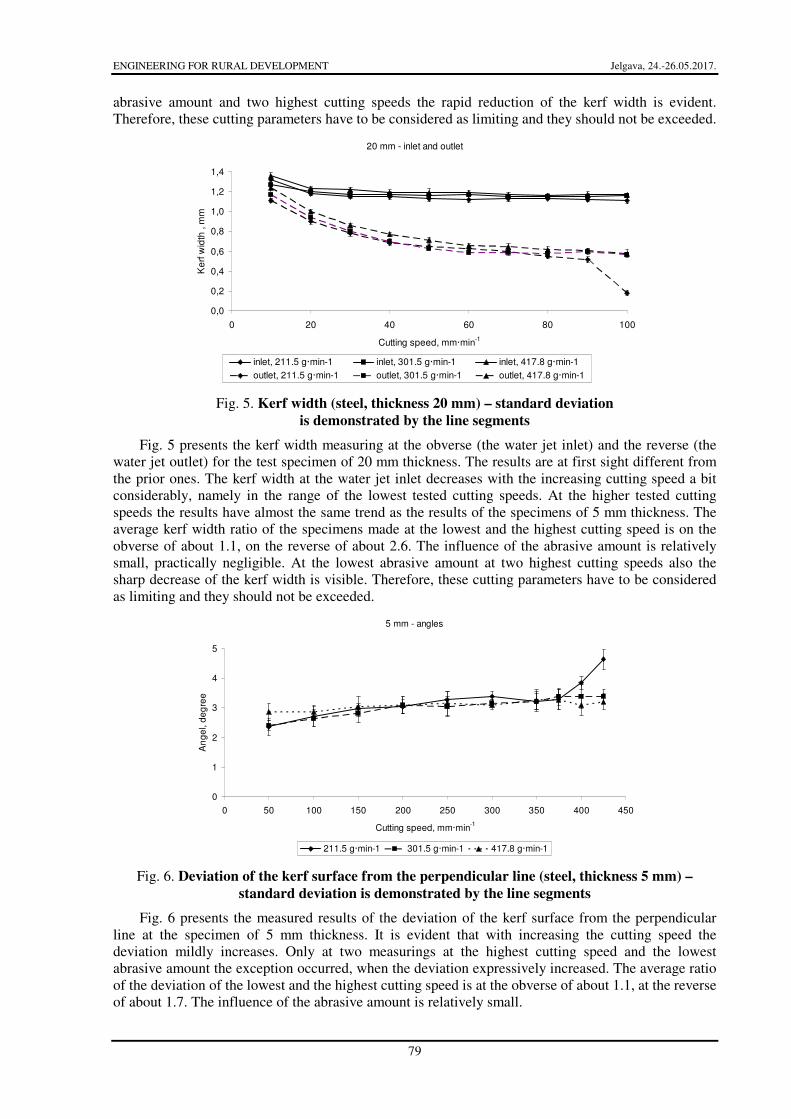
abrasive amount and two highest cutting speeds the rapid reduction of the kerf width is evident. Therefore, these cutting parameters have to be considered as limiting and they should not be exceeded.
20 mm - inlet and outlet
0,0
0,2
0,4
0,6
0,8
1,0
1,2
1,4
0 20 40 60 80 100
Cutting speed, mm·min-1
Ke
rf w
idth
, m
m
inlet, 211.5 g·min-1 inlet, 301.5 g·min-1 inlet, 417.8 g·min-1
outlet, 211.5 g·min-1 outlet, 301.5 g·min-1 outlet, 417.8 g·min-1
Fig. 5. Kerf width (steel, thickness 20 mm) – standard deviation
is demonstrated by the line segments
Fig. 5 presents the kerf width measuring at the obverse (the water jet inlet) and the reverse (the water jet outlet) for the test specimen of 20 mm thickness. The results are at first sight different from the prior ones. The kerf width at the water jet inlet decreases with the increasing cutting speed a bit considerably, namely in the range of the lowest tested cutting speeds. At the higher tested cutting speeds the results have almost the same trend as the results of the specimens of 5 mm thickness. The average kerf width ratio of the specimens made at the lowest and the highest cutting speed is on the obverse of about 1.1, on the reverse of about 2.6. The influence of the abrasive amount is relatively small, practically negligible. At the lowest abrasive amount at two highest cutting speeds also the sharp decrease of the kerf width is visible. Therefore, these cutting parameters have to be considered as limiting and they should not be exceeded.
5 mm - angles
0
1
2
3
4
5
0 50 100 150 200 250 300 350 400 450
Cutting speed, mm·min-1
An
ge
l, d
eg
ree
211.5 g·min-1 301.5 g·min-1 417.8 g·min-1
Fig. 6. Deviation of the kerf surface from the perpendicular line (steel, thickness 5 mm) –
standard deviation is demonstrated by the line segments
Fig. 6 presents the measured results of the deviation of the kerf surface from the perpendicular line at the specimen of 5 mm thickness. It is evident that with increasing the cutting speed the deviation mildly increases. Only at two measurings at the highest cutting speed and the lowest abrasive amount the exception occurred, when the deviation expressively increased. The average ratio of the deviation of the lowest and the highest cutting speed is at the obverse of about 1.1, at the reverse of about 1.7. The influence of the abrasive amount is relatively small.

ENGINEERING FOR RURAL DEVELOPMENT Jelgava, 24.-26.05.2017.
80
20 mm - angles
0,0
0,5
1,0
1,5
2,0
0 20 40 60 80 100
Cutting speed, mm·min-1
An
ge
l, d
eg
ree
211.5 g·min-1 301.5 g·min-1 417.8 g·min-1
Fig. 7. Deviation of the kerf surface from the perpendicular line (steel, thickness 20 mm) –
standard deviation is demonstrated by the line segments
Fig. 7 presents the measured results of the deviation of the kerf surface from the perpendicular line at the specimen of 20 mm thickness. It is evident that with the increasing cutting speed the deviation considerably increases, most considerably at the highest cutting speeds and the lowest abrasive amount. The average ratio of the deviation of cuts made at the lowest and the highest cutting speed is at the obverse of about 1.1, at the reverse of about 2.6. The influence of the abrasive amount is here relatively small, too.
Comparison of the results with the works of other authors has not been done. The author knows no other work that would deal specifically with this topic.
Conclusions
In the article the results of steel cutting of different thickness (5, 10, 15 and 20 mm) are published, using different cutting parameters. During the tests the influence of the cutting speed (in dependence on the material thickness 10 to 425 mm·min-1) and the influence of the used abrasive amount (211.5, 301.5 and 417.8 g·min-1) were monitored. At the specimen cutting only such parameters were used, when the material was cut through in the whole section. These parameters were determined by the preliminary tests.
The specimens were cut using the CNC cutting machine with the water jet technology AW-CT 0806 TKX, the control system AW-CT 1515 TKX, the high pressure pump AccuStream A-6030, cutting head A2, the hopper of the abrasive transport mechanical control AW-ADS 160, the pressure pump KAESER Aircenter SM9 and the pneumatic pump VersaMatic. The cutting of the test specimens was made at the pressure of 3800 Bar.
At the evaluation primarily the kerf width at the inlet and the outlet of the water jet was monitored. The kerf was in the shape of the letter “V”, therefore the deviation of the kerf surface from the perpendicular line was monitored, too. For the measuring the stereoscopic microscope SZP 11-T ZOOM and the digital CMOS camera connected to PC equipped with the Quick Photo Industrial program were used.
It was proved that the deviation of the kerf surface from the perpendicular line was influenced primarily by the cutting speed. The influence of the used abrasive amount was practically insignificant.
The results of the experiments can be applied in practice when cutting steel sheets of thickness from 5 mm to 20 mm. In the future, it is possible, e.g. to explore the cutting conditions for cutting steel sheets smaller or larger thicknesses, or for cutting other metal materials.

ENGINEERING FOR RURAL DEVELOPMENT Jelgava, 24.-26.05.2017.
81
References
1. Novák J. Použitívysokotlakéhokapalinovéhopaprsku v praxi (The high pressure water jet application in practice). Vysokoenergetický kapalinovýpaprsek – využití v čs. průmyslu (The high energy water jet – the use in Czech industry). Praha, ČSVTS, 1989. pp. 5-11. (In Czech).
2. Jirka M., Brožek M., Chmelík V. Řezání vysokoenergetickým kapalinovýmpaprskem (Cutting using the high energy water jet). Jakost, spolehlivost, materiály a technologie (Quality, reliability, materials and technology). May 31, 1995, Prague, Czech Republic, pp. 57-60. (In Czech).
3. Maňková I. Progresívnetechnologie (Progressive technologies). Košice, TU SF Edíciavedeckejaodbornejliteratúry. Vienala, vydavateľstvo a tlačiareňKošice, 2000, 275 p. (In Slovak).
4. Híreš O., Hatala M., Hloch S. Delenie kovových materiálov okružnou pílou, vodným prúdom a plazmovým oblúkom (Parting of metallic materials using circular saw, water jet and plasma-arc). 1. vydání, Ostrava – Poruba, Vydavatelství Jiří Pustina, 2007. 147 p.
5. Ťavodová M., Náprstková N. Hodnoceníkvalitypovrchumateriálupořezání AWJ (Evaluation of material surface quality after AWJ cutting). Strojírenskátechnologie, vol. 17, 2012, pp. 186-192. (In Czech).
6. Kmec J., Kučerka D., Gombár M., Hrmo R., Bičeková L. Delenie materiálov (Cutting of materials). Košice, Technickáuniverzita, 2014. 287 p. (In Slovak).
7. Wang, J. Abrasive Waterjet Machining of Engineering Materials, Monograph Series, Materials Science Foundations, vol. 19, 2003, 27 p.
8. Barcík Š., Kvietiková M., Aláč P. Effect of the chosen parameters on deflection angle between cutting sides during the cutting of agglomerated materials by water jet. Wood Research, vol. 56, 2011, pp. 577-588.
9. Hashish M. The Effect of Beam Angle in Abrasive-Waterjet Machining, ASME J. of Engineering for Industry, vol. 113, 1991, pp. 29-37.
10. Hashish M. The Effect of Beam Angle in Abrasive-Waterjet Machining, ASME J. of Engineering of Industry, vol. 115, 1993, pp. 51-56.
11. Hmadi-Brooghani S.Y., Hassanzadeh H., Kahhal P. Modeling of Single-Particle Impact in Abrasive Water Jet Machining, World Academy of Science, Engineering and Technology, vol. 36, 2007, pp. 243-248.
12. Brožek M. Optimization of adhesive layer thickness at metal bonding using quick-setting adhesives. Manufacturing Technology, vol. 13, 2013, 419-423.
13. Brožek M., Nováková A., Mikuš R. Study of wear resistance of hard facings using welding powders on the NiCrBSi basis. 4th International Conference Trends in Agricultural Engineering 2010. September 7-10, 2010, Prague, Czech Republic, pp. 115-118.
14. Brožek M. Wear resistance of multi-layer overlays. 11th International Scientific Conference Engineering for Rural Development. May 24-25, 2012, Jelgava, Latvia, pp. 210-215.
15. Brožek M. Resistance spot welding of steel sheets of different thickness. 14th International Scientific Conference on Engineering for Rural Development 2015. May 20-22, 2015, Jelgava, Latvia, pp. 72-77.
16. Müller M. Experimental research on load capacity, treatment of adhesively bonded surface and failure process of structural t-joint. Acta Universitatis Agriculturaeet Silviculturae Mendelianae Brunensis, vol. 64, 2016, pp. 473-479.
17. Müller M. Influence of cyclic degradation in saline solution on mechanical properties of adhesive bonds. Manufacturing Technology, vol. 16, 2016, pp. 204-209.
18. Pavelka R., Brožek M. Truck cabin corrosion resistance observation in artificial atmosphere. 13th International Scientific Conference on Engineering for Rural Development. May 29-30, 2014, pp. 174-180.
19. Pavelka R., Brožek M. Progressive method of observation and assessment during corrosion tests with artificial atmosphere. 13th International Scientific Conference on Engineering for Rural Development. May 29-30, 2014, pp. 181-186.