steel & concrete domes design - قباب الخرسانة والمعدتية ستيل
TRANSCRIPT

1
Dr Hamida
2
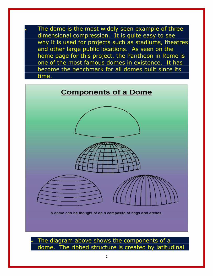
The dome is the most widely seen example of three dimensional compression. It is quite easy to see why it is used for projects such as stadiums, theatres and other large public locations. As seen on the home page for this project, the Pantheon in Rome is one of the most famous domes in existence. It has become the benchmark for all domes built since its time.
The diagram above shows the components of a dome. The ribbed structure is created by latitudinal

3
and longitudinal members. These members intersect to create a strong three dimensional mesh. The dome has a compression ring at the top. In most cases, the foundation acts as a tension ring at the base. In the cases where a dome is used for a type of shelter, a membrane of other covering is attached.
الریاح األفقیة وىق

4
The diagram above shows the horizontal loading of a dome. The major example of horizontal loading is caused by wind. The latitudinal bands transmit the force created by the wind around each side of the structure. The force is dissipated as it travels
القوى الشاقولیةا
5
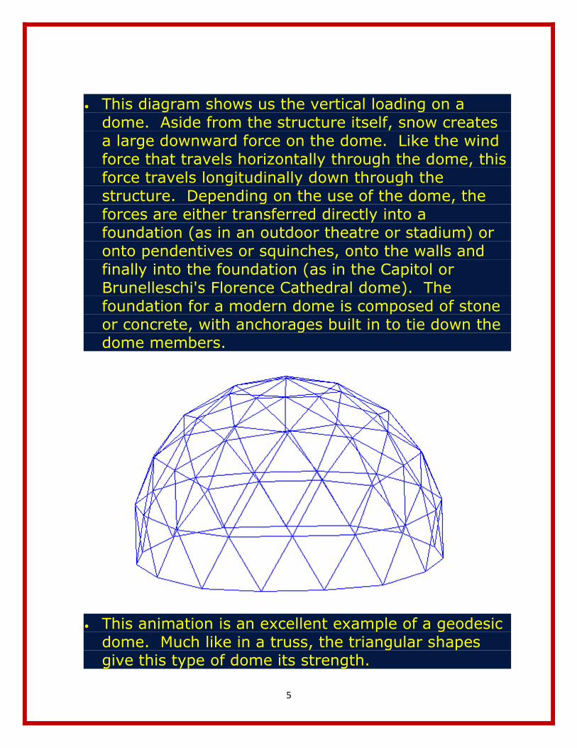
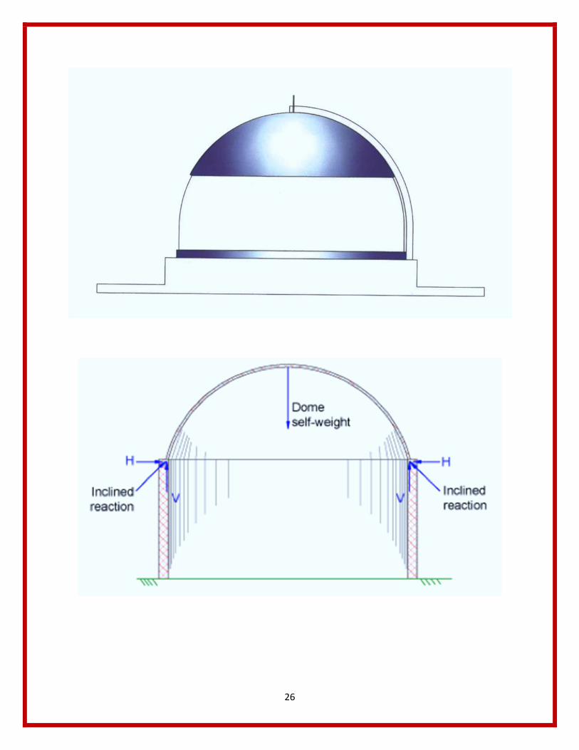
This diagram shows us the vertical loading on a dome. Aside from the structure itself, snow creates a large downward force on the dome. Like the wind force that travels horizontally through the dome, this force travels longitudinally down through the structure. Depending on the use of the dome, the forces are either transferred directly into a foundation (as in an outdoor theatre or stadium) or onto pendentives or squinches, onto the walls and finally into the foundation (as in the Capitol or Brunelleschi's Florence Cathedral dome). The foundation for a modern dome is composed of stone or concrete, with anchorages built in to tie down the dome members.
This animation is an excellent example of a geodesic dome. Much like in a truss, the triangular shapes give this type of dome its strength.
6
7
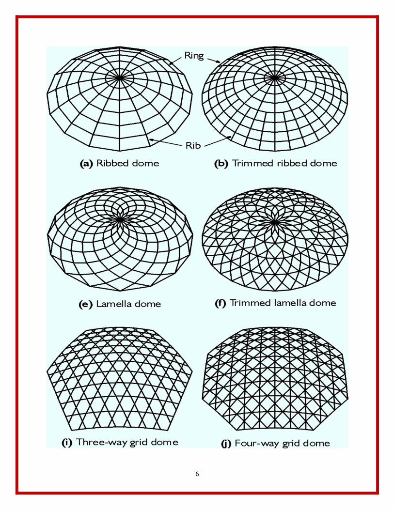
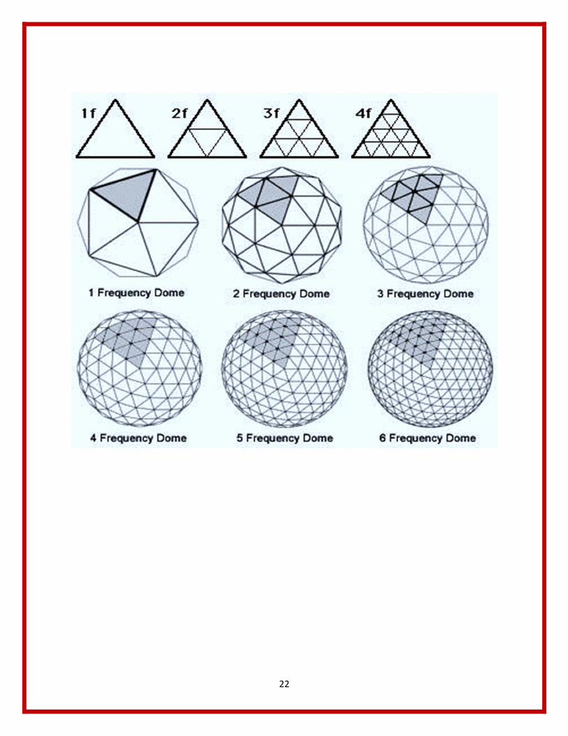
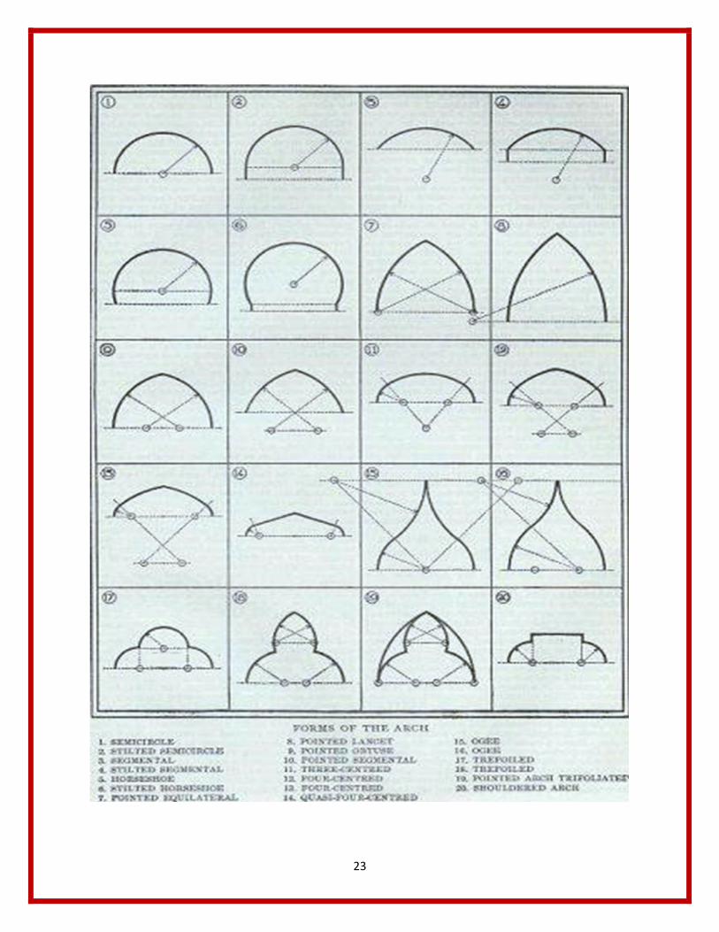
This twelve graphics show many the different types of layouts that can be used to create the ribbing structure of a dome.
Relationship to our class' description of a system:
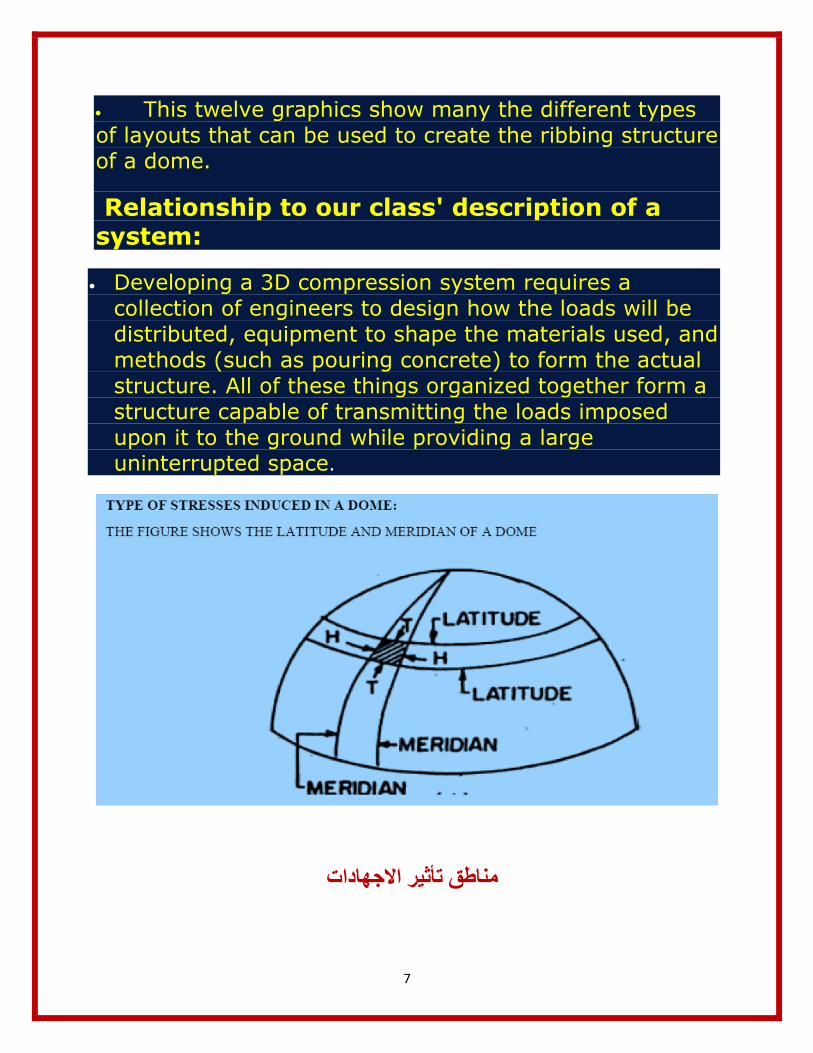
Developing a 3D compression system requires a collection of engineers to design how the loads will be distributed, equipment to shape the materials used, and methods (such as pouring concrete) to form the actual structure. All of these things organized together form a structure capable of transmitting the loads imposed upon it to the ground while providing a large uninterrupted space.
خ
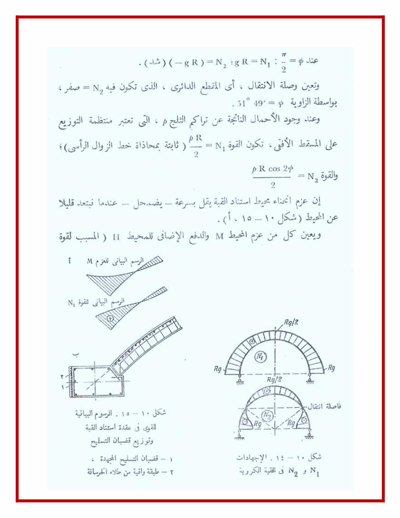
طمناطق تأثیر االجھادات

8
حساب القبة دساتیرد

9
حساب القبة دساتیرد

10

11
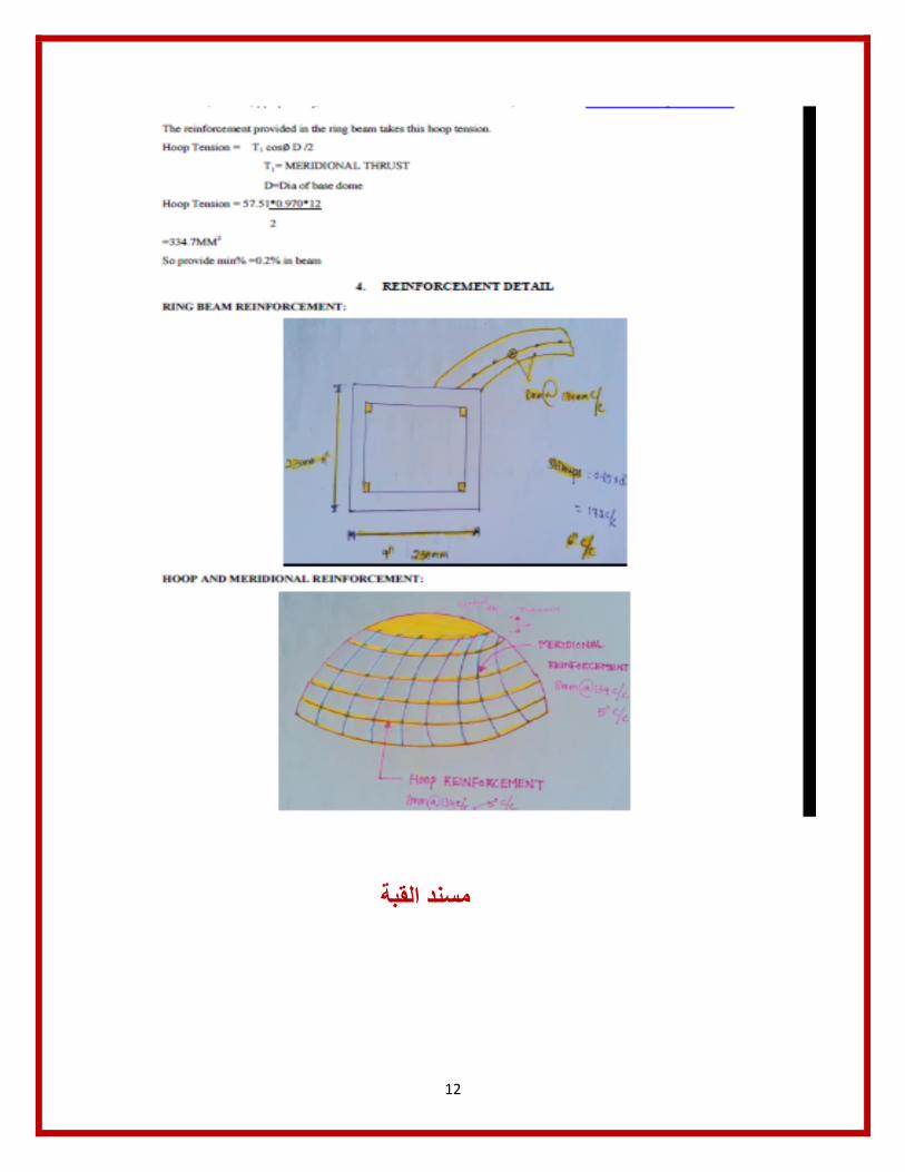
12
مس
القبةمسند مماندممم

13
القبة یدویا حساب

14
15
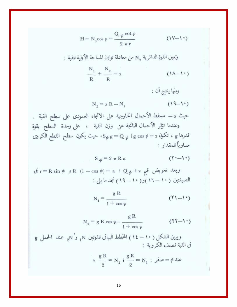
16
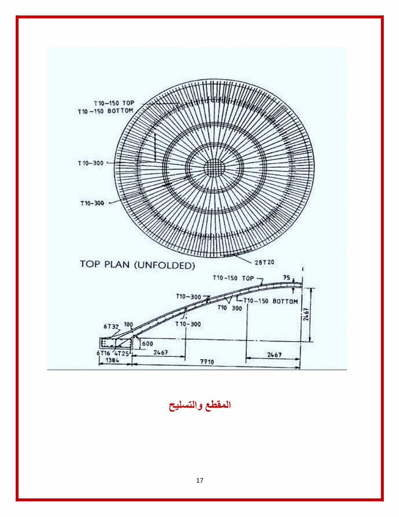
17
والتسلیحالمقطع
18
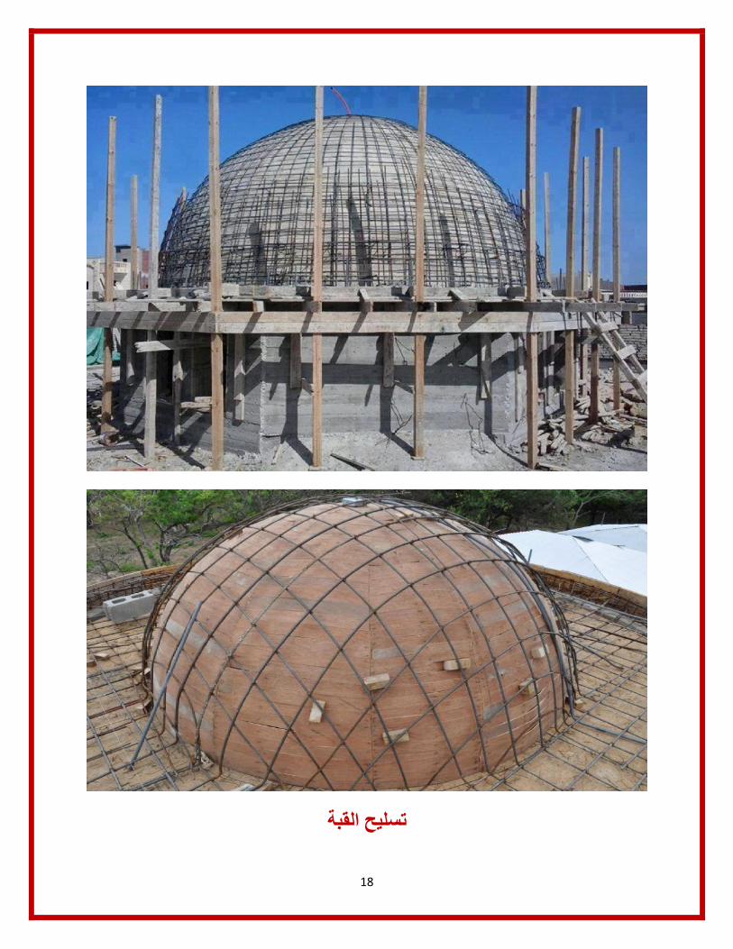
القبةتسلیح
19
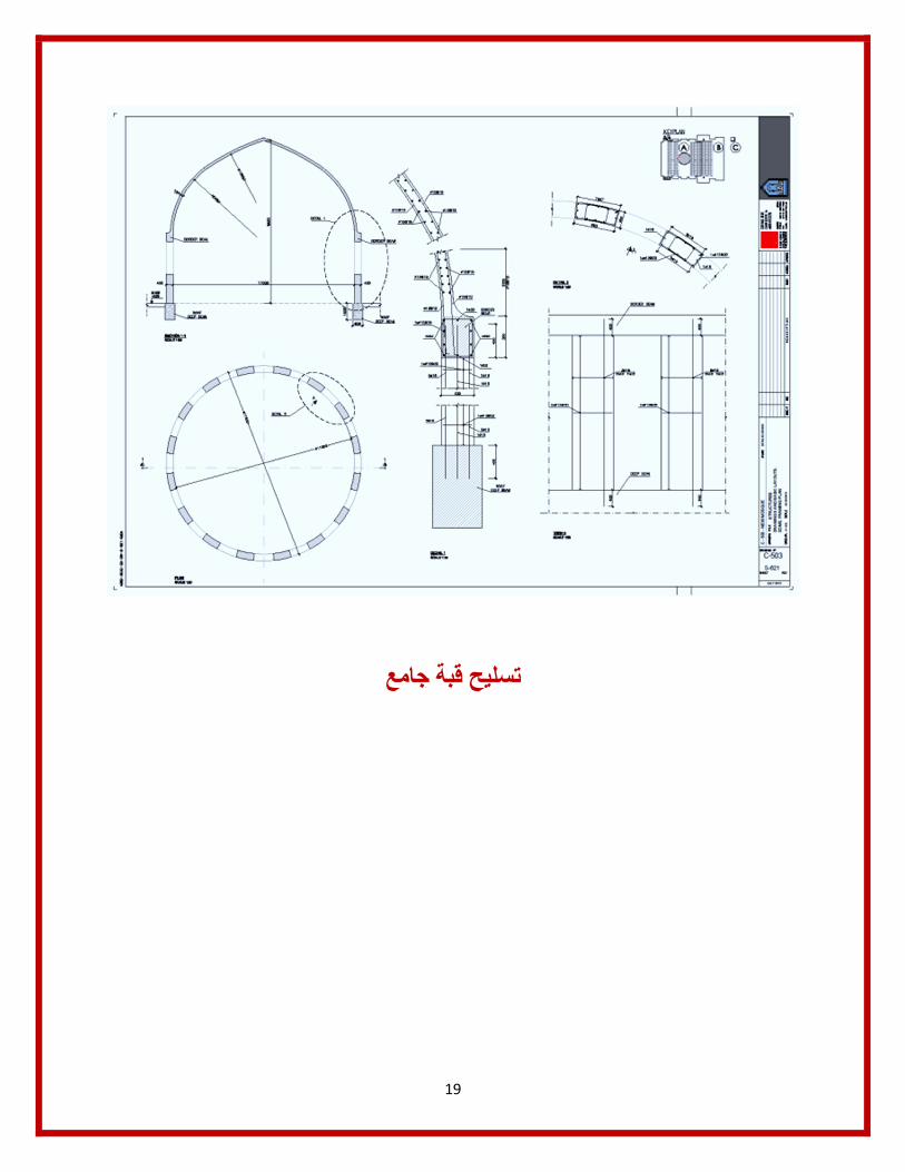
قبة جامعتسلیح
20
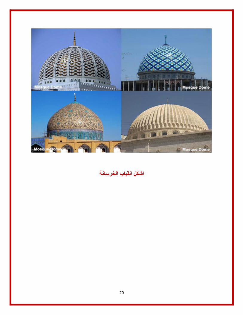
القباب الخرسانةاشكل

21
22
23

24

25
الخاجي حوبیلض السطزریقة ال
26
27
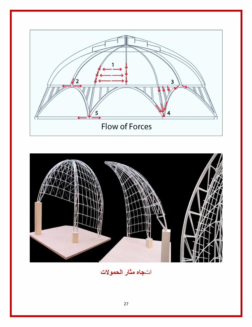
مثار الحموالتجاه ات

28
االجھادات العرضیة والطولیةخطوط
29
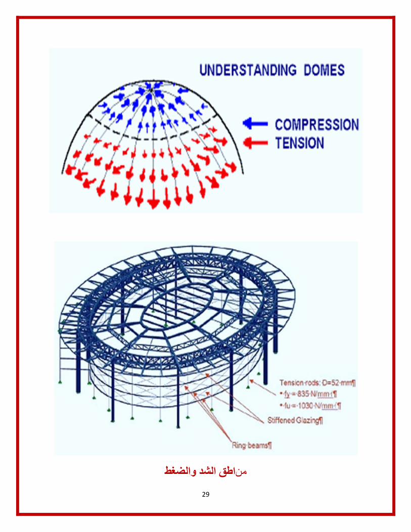
الشد والضغطاطق من
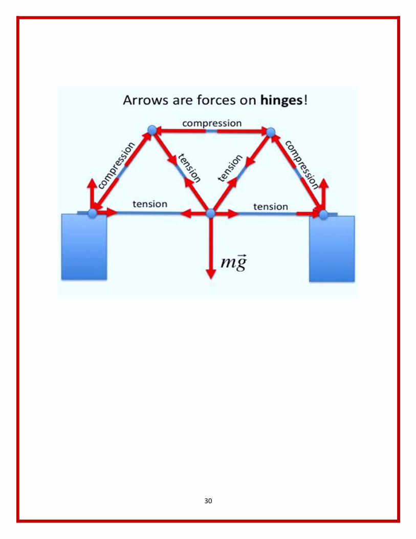
30

31
المعدنیةلقبة ا

32
اعلى القبةلوصل ا

33
الشبكیةالقبة
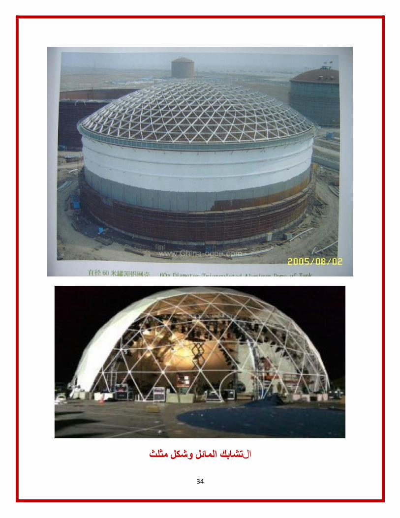
34
المائل وشكل مثلثتشابك ال

35
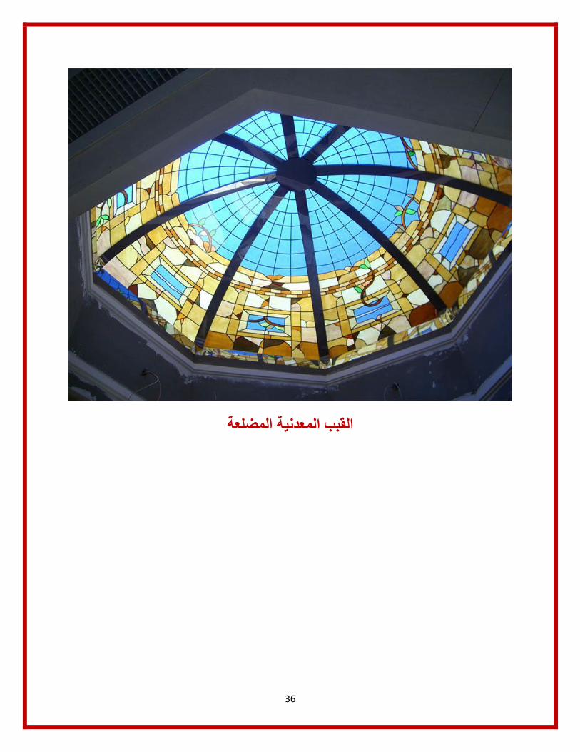
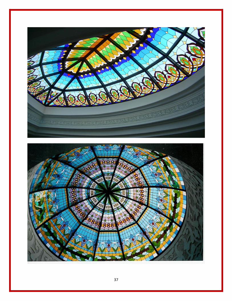
36
المضلعة یةالمعدنالقبب
37
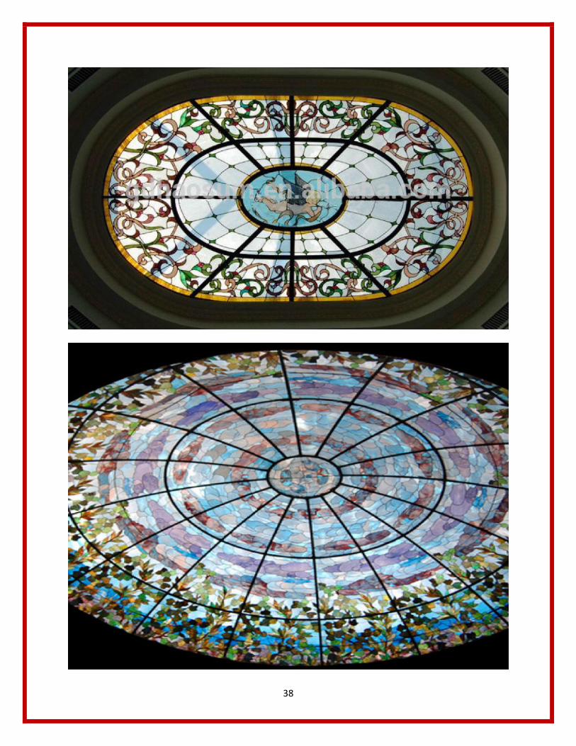
38
39
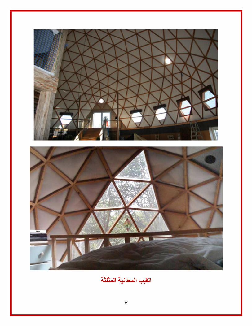
المعدنیة المثلثةالقبب

40

41
المنحنیة الشبكیةاألسقف

42
قبة خرسانة والكمرة الدائرةسلیح ت

43

44

45

46

47

48
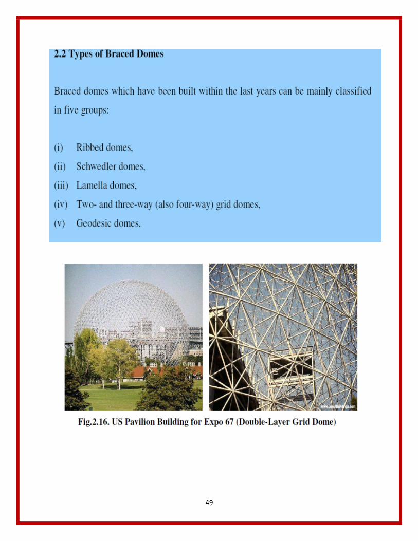
49

50
الحموالت
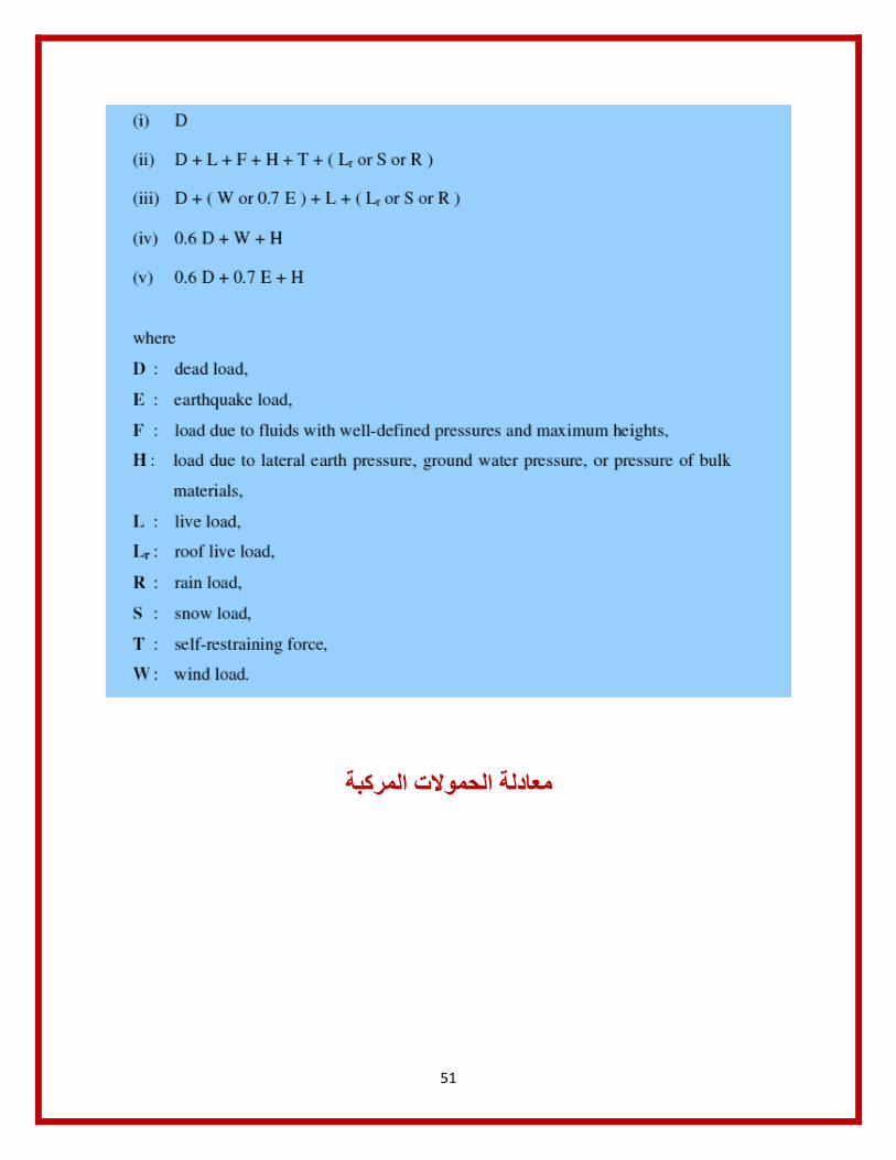
51
الحموالت المركبةمعادلة
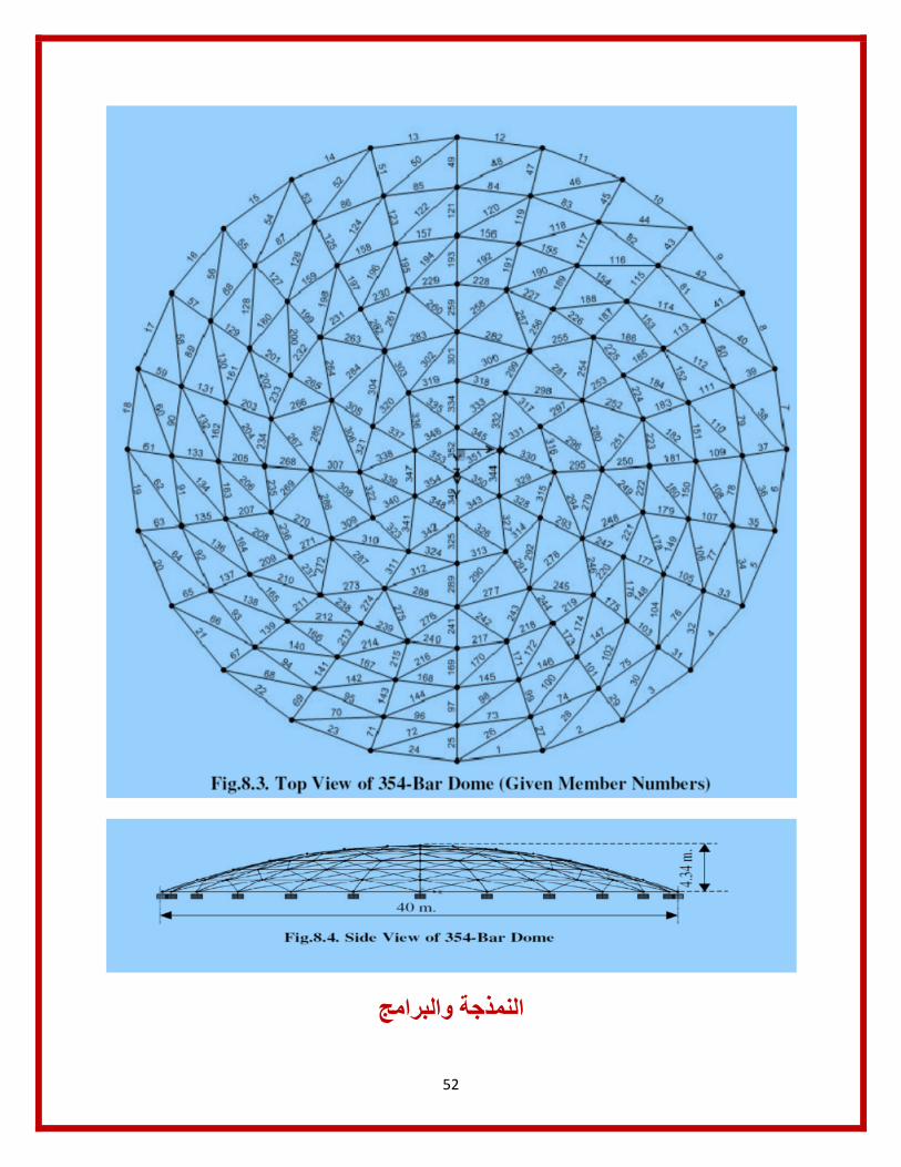
52
والبرامجالنمذجة
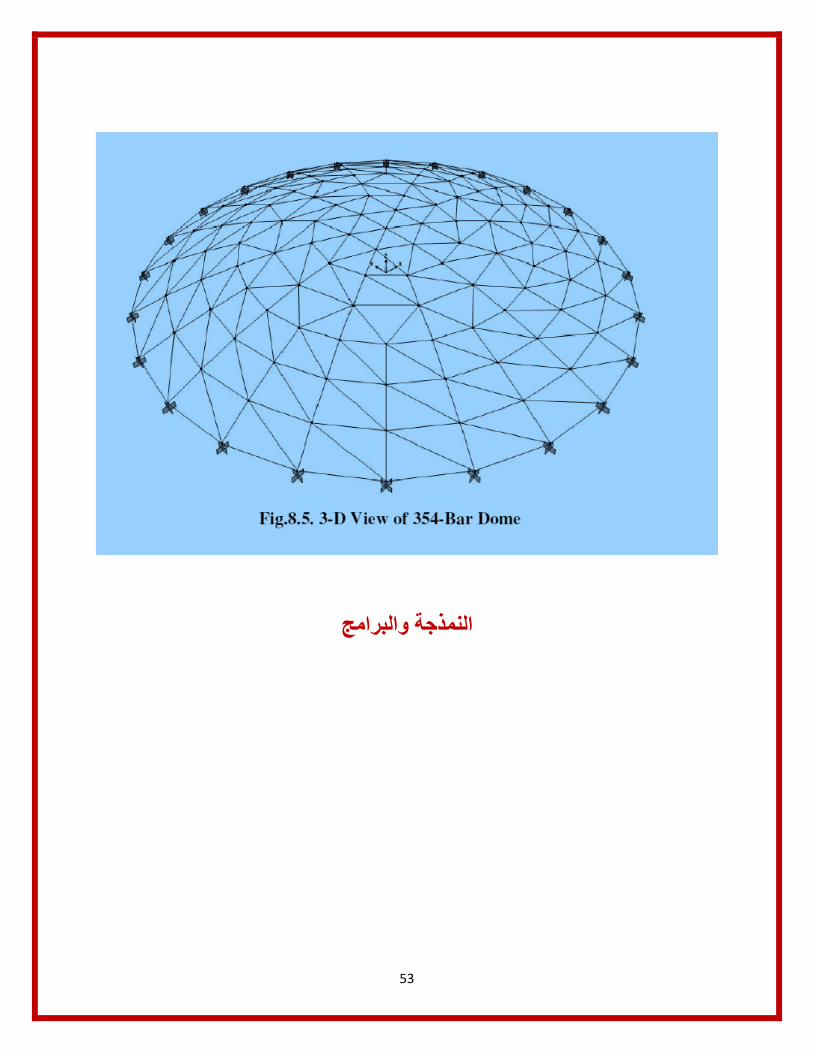
53
والبرامجالنمذجة

54
ح والزالزلالمركبة والریاالحموالت

55
تالحموالشكل
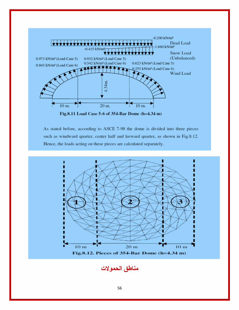
56
الحموالتمناطق

57