steamixtm steam & water hose station and mixing valve · pdf fileconfirm that outlet flow...
TRANSCRIPT

Armstrong International221 Armstrong Blvd., Three Rivers, Michigan, 49093 - USAPh. (269) 279-3602 Toll Free (888) HOT-HOSE (468-4673) Fax (269) 279-3130
Retain this manual for future reference.
STEAMIXTM Steam & Water Hose Station and Mixing ValveInstallation, Operation, and Maintenance Manual
Armstrong International is ISO 9000 Certified

Armstrong International221 Armstrong Blvd., Three Rivers, Michigan, 49093 - USAPh. (269) 279-3602 Toll Free (888) HOT-HOSE (468-4673) Fax (269) 279-3130
Armstrong
ContentsSafety .................................................1
General Description ................................2
Hose Options . . . . . . . . . . . . . . . . . . . . . . . . . . . . . . . . . . . . . . . . . . . . . . . . . 3
Nozzle Options . . . . . . . . . . . . . . . . . . . . . . . . . . . . . . . . . . . . . . . . . . . . . . 3
Specifications .......................................4
Installation ...........................................5
General. . . . . . . . . . . . . . . . . . . . . . . . . . . . . . . . . . . . . . . . . . . . . . . . . . . . . . . . . 5
Cabinet Installation . . . . . . . . . . . . . . . . . . . . . . . . . . . . . . . . . . . . . . . 5
Typical Installation . . . . . . . . . . . . . . . . . . . . . . . . . . . . . . . . . . . . . . . . 6
Temperature Adjustment . . . . . . . . . . . . . . . . . . . . . . . . . . . . . . . . 7
Operation.............................................8
Description . . . . . . . . . . . . . . . . . . . . . . . . . . . . . . . . . . . . . . . . . . . . . . . . . . . 8
Operator Instructions . . . . . . . . . . . . . . . . . . . . . . . . . . . . . . . . . . . . . 9
Periodic Maintenance ............................ 10
Repair Procedures ................................ 11
Mixing Valve . . . . . . . . . . . . . . . . . . . . . . . . . . . . . . . . . . . . . . . . . . . . . . . . . 11
Diaphragm . . . . . . . . . . . . . . . . . . . . . . . . . . . . . . . . . . . . . . . . . . . . . . . . . . . . 12
Water Flow Regulator . . . . . . . . . . . . . . . . . . . . . . . . . . . . . . . . . . . . 13
Troubleshooting ................................... 14
Parts ................................................ 16
Diagram. . . . . . . . . . . . . . . . . . . . . . . . . . . . . . . . . . . . . . . . . . . . . . . . . . . . . . . . 16
Kit List . . . . . . . . . . . . . . . . . . . . . . . . . . . . . . . . . . . . . . . . . . . . . . . . . . . . . . . . . . 17
Limited Warranty and Remedy ................. 18
Notes................................................ 19

Armstrong InternationalIOM-784STEAMIX Hose Station
Page 1 of 22
Safety
— injury or death and property damage are imminent
— injury or death and property damage are possible
— potential property damage, expensive repairs, and/or voiding the warranty may result
Icon LegendIf instructions are not followed:
The STEAMIX Hose Station and Mixing Unit is not designed for and should never be used to deliver:• Hot water for human showering, bathing, or hand washing• Water at any temperature to emergency fixtures of any kind
Failure to comply with safety warnings may result in serious injury, including severe burns from scalding water and flash steam.
Wear protective gloves, garments, and safety glasses when using this unit.
Do not use this mixing valve with superheated steam.
Never point nozzle at yourself or anyone else.
Do not use if damaged or not properly functioning.
Burn hazard:• Avoid touching steam inlet and valve body.• Avoid exposure to spray.

Armstrong InternationalIOM-784STEAMIX Hose Station
Page 2 of 22
General Description STEAMIX units are designed to supply hot water in only industrial applications, such as vessel filling and hose down, by mixing steam and water at a single use point.
Armstrong reserves the right to make design or specification changes without notification.
Models are available from a basic mixing valve only (shown below) to a complete hose station (shown at right).
Multiple options exist for materials of specific components, as well as hoses and nozzles shown on following page.
Consult Armstrong for advice regarding your specific application.
The mixing valve is a diaphragm-actuated, direct-steam-injection valve, typically installed on a hose rack, and equipped with isolation valves, a length of hose, and a nozzle.
STEAMIX mixes steam with cold water to produce water with a variable output temperature adjusted using the temperature control handle. (The temperature range varies from cold to boiling depending on the inlet pressures available.) A locked, pre-set temperature is possible by removing the control handle and installing an optional locking set.
Among engineered safety features:• Water pressure below 20 psi will not actuate poppet valve to allow steam entry.• Diaphragm damage or failure will prohibit opening poppet valve and steam entry.
Note: STEAMIX's efficient use of steam makes it possible to deliver boiling water that may flash to steam upon reaching the atmosphere. This condition does not indicate valve failure or passage of live steam. Armstrong recommends installing optional locking set to avoid use of boiling water.

Armstrong InternationalIOM-784STEAMIX Hose Station
Page 3 of 22Nozzle Options
Hose Options
Color Pressure Ratingpsi (bar)
Temperature Rating°F (°C)
Safety yellow (standard) 400 (27.6) 190 (87.8)Boston black 225 (15.5) 180 (82.2)Boston red 300 (20.7) 180 (82.2)White creamery 150 (10.3) 180 (82.2)Generic white Varies (consult Armstrong) Varies (consult Armstrong)
Note: All hoses meet operating conditions. Color is based on preference or company-specific safety indication requirements.
Nozzle OptionsModel* Flow Rate
gpm (L/min) @ 100 psi (bar)D19472 (038-10) [standard] 10 (37.9)D19473 (038-16) 16 (60.6)D19474 (038-22) 22 (83.3)D11285 (TG) [premium] 6.5 (24.6)
* Old part number shown in parentheses.

Armstrong InternationalIOM-784STEAMIX Hose Station
Page 4 of 22
Specifications
Note: Low inlet pressures will significantly reduce outlet flow.
Steam and water pressures shown as psi (bar).Flow rate shown as gal/min (L/min).
Typical flow rates at various temperatures and pressures shown below. Temperature categories indicate approximately:• User safe temperature (ca. 120 °F/48 °C)• Hot hose-down temperature (ca. 150–160 °F/65–71 °C)• Common bacteria kill temperature (ca. 180 °F/82 °C; does not
imply sterilization capability)
Parameter psi(g) BarMinimum inlet pressure (steam & water) 20 1.4Maximum static pressure (steam & water) 150 10Optimal pressure (steam & water) 50–75 3.5–5Maximum pressure loss across mixing valve 60 4Minimum pressure loss across mixing valve 7 0.4
Maximum pressure loss ratio in favor of either supply: 10:1
55 °F (31 °C) Temperature RiseSteam
Water 20 (1.4) 45 (3) 75 (5) 100 (7)
22 (1.5) 9.6 (26.1) 10.2 (38.6) 10.2 (38.6) 10.2 (38.6)45 (3) 9.6 (26.1) 13.2 (49.9) 13.2 (49.9) 13.2 (49.9)60 (4) 9.6 (26.1) 13.8 (52.2) 15.7 (59.4) 15.7 (59.4)
100 °F (56 °C) Temperature RiseSteam
Water 20 (1.4) 45 (3) 75 (5) 100 (7)
22 (1.5) 3.6 (13.6) 6.9 (26.1) 8.3 (31.4) 8.5 (32.1)45 (3) 3.6 (13.6) 6.9 (26.1) 9.4 (35.5) 9.9 (37.4)60 (4) 3.6 (13.6) 6.9 (26.1) 9.4 (35.5) 10.5 (39.7)
135 °F (73 °C) Temperature RiseSteam
Water 20 (1.4) 45 (3) 75 (5) 100 (7)
22 (1.5) 2.5 (9.4) 5.0 (18.9) 6.6 (24.9) 7.2 (27.2)45 (3) 2.5 (9.4) 5.0 (18.9) 7.2 (27.2) 8.0 (30.2)60 (4) 2.5 (9.4) 5.0 (18.9) 7.2 (27.2) 8.0 (30.2)

Armstrong InternationalIOM-784STEAMIX Hose Station
Page 5 of 22Cabinet Installation
Installation
Note: STEAMIX units come pre-assembled—using anaerobic thread sealant—and pressure tested.
Install in a location that permits access for adjustment and servicing.
Note:• In systems with widely fluctuating steam
pressure install regulator set to lowest known pressure at least 6 feet upstream from valve.
Cabinet Installation
On flush mount cabinets mounting flange typically extends 2" (50.8 mm) beyond cabinet wall.
Plumb drain out bottom of cabinet.
• Steam trap between 6 and 15 feet upstream of valve is recommended.
Eliminate water hammer. Damage caused by water hammer is not covered by warranty.
12" (304.8 mm)
28" (711.1 mm)
48" (1219.2 mm)
Note: Installation must comply with all applicable federal, state, and local sanitary, construction, plumbing and regulatory codes.
General

Armstrong InternationalIOM-784STEAMIX Hose Station
Page 6 of 22Typical Installation
Note: Code or regulatory requirements may include back-flow preventers (single or double action) or vacuum breakers, which are not listed above.
Firmly tighten both gland screws equally before operation.
Caution: Do not apply excessive torque on supplied fittings. Use two wrenches when assembling.
Note: Inlet lines must have components shown. Some may be supplied depending on model.
Outlet must have:• Thermometer• Union (if hard piped)• Minimal restrictionNote: Pressure or temperature gauges must not interfere with water flow.
Install shortest length of hose required.
Typical Installation
Install using mounting plate. Do not rest unit on piping.
Use least restrictive nozzle required.
Union
Shut-off valve
Strainer
Check valve
Steam Inlet
Water InletNote: Components are called out on only one line below.

Armstrong InternationalIOM-784STEAMIX Hose Station
Page 7 of 22Temperature Adjustment
Turn temperature regulating handle CW as far as it will go (may require several revolutions).
Loosen set screw at base and remove water flow regulator locking cap.
Turn cold water regulator screw under cap CCW until fully open (mixing valve in full cold position).
Open inlet isolation valves (and spray nozzle if attached) to obtain maximum flow.
Turn temperature regulating handle CCW until desired temperature is obtained. Note: If desired temperature cannot be obtained with temperature control fully open, turn water flow regulator screw CW until temperature is achieved.
Replace water flow regulator locking cap.
Temperature Adjustment
Note: To lock temperature and prevent adjustment, remove temperature regulating handle and install tamper resistant locking set (P/N D14924).
Note: This adjustment is required only if output temperature is too low at maximum valve setting.
1
2
34
5
6
Caution: Once temperature is set, operators should not attempt to adjust water flow restrictor.
TEMPERATURECONTROL HANDLE
SPRING
MIXINGCHAMBER
DIAPHRAGM
STEAMINLET WATER
INLET
POPPETVALVE
Armstrong InternationalIOM-784STEAMIX Hose Station
Page 8 of 22Description
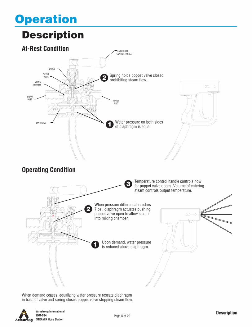
Water pressure on both sides of diaphragm is equal.
Spring holds poppet valve closed prohibiting steam flow.
At-Rest Condition
1
2
Operating Condition
1 Upon demand, water pressure is reduced above diaphragm.
2When pressure differential reaches 7 psi, diaphragm actuates pushing poppet valve open to allow steam into mixing chamber.
Temperature control handle controls how far poppet valve opens. Volume of entering steam controls output temperature.
3
When demand ceases, equalizing water pressure reseats diaphragm in base of valve and spring closes poppet valve stopping steam flow.
Operation Description

Armstrong InternationalIOM-784STEAMIX Hose Station
Page 9 of 22Operator Instructions
� Use minimally required temperature for activity. Keep steam pressure at or below 100 psi. (Although units are rated for 150 psi, pressures above 100 psi have negligible effect.)
� Close upstream steam and water valves after use. Do not use nozzle as long-term flow-control device.
� Bleed pressure from hose after closing valves.Caution: Leaving hose under pressure may lead to premature degradation or rupture.
� Avoid kinks in hose.
� Return hose to holder after use.
Operator Instructions
Do not use valve if hose is ripped or damaged in any way.
Caution: Always check and be aware of last position of temperature control handle. Mixing valve will automatically rise to previous temperature setting. Armstrong recommends turning temperature control handle to low temp setting (fully CW) after each use.

Armstrong InternationalIOM-784STEAMIX Hose Station
Page 10 of 22
Periodic Maintenance
Interval TaskShift or Daily(frequent testing will not degrade unit)
Safety Check1. Set mixing valve for normal operation.2. Start outlet water flowing.3. Shut off a remote water supply valve.4. Confirm that outlet flow stops immediately and no live steam is passed from mixing valve.
If live steam is passed, do not use hose station!As necessary Evenly tighten both gland plate screws to prevent leakage through seal.As necessary (based on water quality)
Disassemble mixing valve and clean internal parts with good quality, commercial, inhibited de-scaler.
6 months
Inspect all valve seats for wear.Inspect seals and gaskets for nicks and tears.Inspect diaphragm.Lubricate all moving parts. Use high quality silicone lubricant only. Do not use petroleum-based lubricants.Check supply shut-off valves.
Maintenance recommendations are based on typical usage. Frequency may need to be adjusted for your actual usage.The information below is intended only for Maintenance personnel or others with necessary expertise.

Armstrong InternationalIOM-784STEAMIX Hose Station
Page 11 of 22Mixing Valve
Repair Procedures Mixing ValveNote: Always replace O-rings and gaskets. Use applicable parts kit.
Shut off steam and water supply lines.1
Unscrew spindle CW and remove from bonnet.Caution: To avoid damaging diaphragm, do not twist poppet valve.
7
Remove bonnet and spindle assembly.6
While maintaining pressure against bonnet, remove six retaining screws.5
Remove gland plate screws and gland plate.4
Remove retaining screw and washers from temperature regulating handle and remove handle.
3
Open outlet shut-off valve and spray nozzle, if equipped.2
Carefully remove spring and poppet valve from body.9
Carefully push out gland seal packing.8
Remove diffuser and gasket. De-scale diffuser using commercial, inhibited de-scalent.
10
Inspect diffuser seat; replace body if damaged.11

Armstrong InternationalIOM-784STEAMIX Hose Station
Page 12 of 22Diaphragm
Diaphragm
Note:• Recommended procedure is to check complete
mixing valve when replacing diaphragm.• Replace O-rings.
De-scaling valve body and actuating staff is recommended. Do not allow de-scaler to contact diaphragm if reusing it.
Reassemble in reverse order using silicone based lubricant:• Ensure that base O-ring, connecting tube, and connecting tube
O-ring seat properly.• Tighten screws using diagonal pattern.• Press triangular actuating staff visible in top of valve body
(thermometer port) to confirm free and even movement of diaphragm assembly.
Disconnect mixing valve from piping.1
Remove screws from valve body.2
Carefully separate base from body. Retain connecting tube.Note: Diaphragm assembly may remain attached to either base or body.
3
Remove diaphragm assembly and inspect. Replace if worn or damaged.
4
Base O-Ring
Connecting Tube
Connecting Tube O-Ring

7
Armstrong InternationalIOM-784STEAMIX Hose Station
Page 13 of 22Water Flow Regulator
Water Flow Regulator
Shut off steam and water supply lines.1
Open outlet shut-off valve (and nozzle, if equipped).2
Remove regulator assembly.4
Remove retaining ring.5
Replace gasket and O-rings and lubricate.Note: Use only silicone based lubricant.
7
Reassemble in reverse order.8
Check for leaks.9
Remove set screw and locking cap.3
Unscrew spindle.6
Set temperature parameters. Go to page 7.10

Armstrong InternationalIOM-784STEAMIX Hose Station
Page 14 of 22
Troubleshooting Allow mixing valve to cool before beginning. Components and water may be hot.
Troubleshooting
Problem Probable Cause Correction
Inability to obtain hot water
Failed diaphragm Replace
Steam diffuser clogged (minerals) Clean or replace
Insufficient steam supply Increase supply
High pressure loss ratio
1. Use shorter or less restrictive hose.2. Use less restrictive nozzle.3. Eliminate unnecessary flow restrictions such as hose reels or wands.4. Install pressure regulators and reduce inlet pressure differential (but keep adequate supply pressures).
Inability to adjust outlet temperature accurately High pressure loss ratio
1. Use shorter or less restrictive hose.2. Use less restrictive nozzle.3. Eliminate unnecessary flow restrictions such as hose reels or wands.4. Install pressure regulators and reduce inlet pressure differential (but keep adequate supply pressures).
Inability to stabilize outlet temperature High pressure loss ratio
1. Use shorter or less restrictive hose.2. Use less restrictive nozzle.3. Eliminate unnecessary flow restrictions such as hose reels or wands.4. Install pressure regulators and reduce inlet pressure differential (but keep adequate supply pressures).
Note: As indicated below, the great majority of performance problems are due to high pressure loss ratio (above 10:1). Pressure loss ratio (PLR) is the ratio of the two inlet pressures after subtracting the back pressure from each. In most cases a high PLR is the result of excessive back pressure, usually caused by a restrictive condition of some kind on the outlet side—too long a hose or too restrictive a nozzle, for example. Back pressure is difficult to measure precisely and it is not necessary to do so. The key is not the actual value, but the realization that it is the problem. High PLR may be corrected at either the inlet or outlet. Correcting it at the outlet side is both easier and cheaper and should be tried first. On the inlet side correction involves installing a pressure reducing valve on the line with the highest pressure.
To diagnose PLR:1. Identify static inlet steam and water pressures at point of installation. Note a ratio in excess of 2:1.2. Uncoil hose completely and ensure that it is not kinked or blocked. If unit operates correctly, excessive back pressure is being caused by hose.3. Remove primary outlet restriction (e.g., nozzle). If unit operates correctly, nozzle is too restrictive.4. If neither is problem and no other cause can be identified, operate hose station and note:
• Flow rate• Output water temperature
5. Contact Armstrong for assistance. Have noted values at hand.

Armstrong InternationalIOM-784STEAMIX Hose Station
Page 15 of 22
Troubleshooting
Problem Probable Cause Correction
Noisy operation High pressure loss ratio
1. Use shorter or less restrictive hose.2. Use less restrictive nozzle.3. Eliminate unnecessary flow restrictions such as hose reels or wands.4. Install pressure regulators and reduce inlet pressure differential (but keep adequate supply pressures).

22
18
17c
17d
17b
17a
21
20
19
15
14
13
12
11c
11b
11a
10
9
8
7
6
5
4
3
2a
2b
1c
1b
1a
23
16e
16a16b
16c
16d
24
Armstrong InternationalIOM-784STEAMIX Hose Station
Page 16 of 22
Parts
Use only performance-matched replacement parts from Armstrong. Do not substitute any components.
Note: Consult Armstrong for parts in units with serial number below 10000.
Diagram

Armstrong InternationalIOM-784STEAMIX Hose Station
Page 17 of 22
Kit ListRef. Description Kit Reference (See Ledger) Qty.1a Temperature Control Lever Retaining Screw 11b Lock Washer 11c Flat Washer 12a Temperature Control Lever Boss 12b Temperature Control Lever 13 Gland Plate Retaining Screw 24 Gland Plate 15 Gland Packing 16 Temperature Control Spindle B5373-1 17 Bonnet Retaining Screw 68 Bonnet D2904 19 Upper Gasket 110 Return Spring 111a Poppet Valve 111b Facing 111c Retainer 112 Steam Diffuser 113 Diffuser Copper Gasket 114 Cover Screw B5650 (Includes all 8 screws) 815 Body D4354 116a Locking Cap 116b Set Screw 116c Retaining Ring 116d Spindle 116e Water Flow Regulator Seat 117a Actuating Spindle 117b Diaphragm Top Plate 117c Diaphragm Clamp Plate 117d Nut 118 Diaphragm Only 119 Base O-Ring 120 Connecting Tube 121 Connecting Tube O-Seal 122 Base D3443 123 Water Flow Regulator Spindle O-Seals 224 Water Flow Regulator Copper Gasket 1-- Locking Cap, Tamper Resistant (optional) Not Shown 1
Kit Reference
Kit Part No.
D33834B5649D14923D32602B5648B5651 (Brass)D40888 (Stainless)D32600D32601
1 2 3
8
12345
6
7
1 2 31 2 31 31 3
2 33
83 5 73
23
83 4 5 744444
84 5 7
6
6666
7777
8785 7
85 785 7
85 6 785 6 7

Armstrong InternationalIOM-784STEAMIX Hose Station
Page 18 of 22
Armstrong Hot Water, Inc. ("Armstrong") warrants to the original user of those products supplied by it and used in the service and in the manner for which they are intended, that such products shall be free from defects in material and workmanship for a period of one (1) year from the date of installation, but not longer than 15 months from the date of shipment from the factory [unless a special warranty period applies, as listed below]. This warranty does not extend to any product that has been subject to misuse, neglect, or alteration after shipment from the Armstrong factory. Except as may be expressly provided in a written agreement between Armstrong and the user, which is signed by both parties, Armstrong DOES NOT MAKE ANY OTHER REPRESENTATIONS OR WARRANTIES, EXPRESS OR IMPLIED, INCLUDING, BUT NOT LIMITED TO, ANY IMPLIED WARRANTY OF MERCHANTABILITY OR ANY IMPLIED WARRANTY OF FITNESS FOR A PARTICULAR PURPOSE. The sole and exclusive remedy with respect to the above limited warranty or with respect to any other claim relating to the products or to defects or any condition or use of the products supplied by Armstrong, however caused, and whether such claim is based upon warranty, contract, negligence, strict liability, or any other basis or theory, is limited to Armstrong's repair or replacement of the part or product, excluding any labor or any other cost to remove or install said part or product, or, at Armstrong's option, to repayment of the purchase price. As a condition of enforcing any rights or remedies relating to Armstrong products, notice of any warranty or other claim relating to the products must be given in writing to Armstrong: (i) within 30 days of last day of the applicable warranty period, or (ii) within 30 days of the date of the manifestation of the condition or occurrence giving rise to the claim, whichever is earlier. IN NO EVENT SHALL ARMSTRONG BE LIABLE FOR SPECIAL, DIRECT, INDIRECT, INCIDENTAL OR CONSEQUENTIAL DAMAGES, INCLUDING, BUT NOT LIMITED TO, LOSS OF USE OR PROFITS OR INTERRUPTION OF BUSINESS. The Limited Warranty and Remedy terms herein apply notwithstanding any contrary terms in any purchase order or form submitted or issued by any user, purchaser, or third party and all such contrary terms shall be deemed rejected by Armstrong.
Special Warranty Periods are as follows:
Limited Warranty and Remedy
Armstrong Hot Water Group safety yellow washdown hose is a Goodyear® product, which is manufactured for industrial hot water washdown applications up to 190 °F.The fittings at each end are installed by trained employees using specially calibrated crimping equipment, performance matched and sized ferrules with a stainless steel anti-kink spring guard at the hose inlet.Industrial washdown can be a rigorous procedure and there is a fine relationship between weight and flexibility to reduce user fatigue and increased strength and durability which promotes user safety. As such, Armstrong supplied washdown hose should not be considered to be functionally infallible. However, provided that the hose is installed as supplied, users are correctly trained, the hose is commissioned, operated, routinely inspected and maintained, the risk of injury due to product failure, while never eliminated, may be reduced substantially.The Armstrong Hot Water Group washdown hose has a variable service life depending upon factors such as the frequency of use, site/application conditions and operator care.Washdown hoses, which are operated in harsh industrial environments, particularly those used with high temperature water, should be subject to regular inspection and replacement.Armstrong Hot Water Group does not recommend and will not perform after-installation hose repair. Hose rupture or fatigue-related damage might be a sign that the hose has reached the end of its service life and a replacement hose is required. If the choice is made at the plant level to repair a washdown hose by installing new fittings, Armstrong Hot Water Group recommends that a professional hose distributor/supplier be contacted.After-installation repair or secondary “re-fitting” of a Washdown Hose supplied by Armstrong Hot Water Group voids all warranties and frees Armstrong Hot Water Group from all liability.Standard Warranty PolicyThis is a fair wear and tear warranty and Armstrong Hot Water Group reserves the right to be final arbiter. This warranty is in lieu of all other warranties.Armstrong Hot Water Group does not make any other representations or warranties, express or implied, including, but not limited to, any implied warranty of merchantability or any implied warranty of fitness for a particular purpose.In no event shall Armstrong Hot Water Group be liable for special, direct, indirect, incidental or consequential damages, including, but not limited to, loss of use, loss of profits or interruption of business.GeneralWarranty Candidacy Period:All washdown hoses supplied by Armstrong Hot Water Group are a candidate for warranty replacement for a period of one year as indicated by the date code stamped upon the fittings.
Warranty Replacement ProgramLess than 3 months service—Full ReplacementMore than 3 but less than 6 months service—Replace Hose at 25% of current priceMore than 6 but less than 9 months—Replace Hose at 50% of current priceMore than 9 but less than 12 months—Replace Hose at 75% of current priceFor further information please call our technical department at 1-888-HOT HOSE.

Armstrong InternationalIOM-784STEAMIX Hose Station
Page 19 of 22
Notes

Armstrong InternationalIOM-784STEAMIX Hose Station
Page 20 of 22
Notes

Armstrong InternationalIOM-784STEAMIX Hose Station
Page 21 of 22
Notes

Armstrong InternationalIOM-784STEAMIX Hose Station
Page 22 of 22
Notes