steadystatesolutionsto dynamicallyloadedperiodicstructures ... · steadystatesolutionsto...
TRANSCRIPT

STEADYSTATESOLUTIONSTO
DYNAMICALLYLOADEDPERIODICSTRUCTURES
Anthony J. KalinowskiNaval Underwater Systems Center
SUMMARY
The paper treats the general problem of solving for the steady state (timedomain) dynamic response (i.e., NASTRANrigid format-8) of a general elasticperiodic structure subject toa phase difference loading of the type encounteredin traveling wave propagation problems. Two types of structural configurationsare considered; in the first type, the structure has a repeating pattern over aspan that is long enough to be considered, for all practical purposes, asinfinite; in the second type, the structure has structural rotational symmetryin the circumferential direction. Due to the periodic nature of the structureand the traveling wave characteristics of the loading, one need only "cut out"and subsequently model a typical periodic region of the total structure,wherein appropriate periodic boundary conditions (i.e., unknown forces and dis-placements are forced equal, except for unknown phase angle, for correspondingpoints on both cuts) are used along the cuts. The paper presents both thetheory and a corresponding set of DMAPinstructions which permits the NASTRANuser to automatically alter the rigid format-8 sequence to solve the intendedclass of problems. The new input to a standard version NASTRANrun is a setof alter cards, PARAMcards, and direct input matrix(DMl) partitioning arrayswhich are needed for the purpose of partitioning and correspondingly restruc-turing the internal NASTRANmass, damping and stiffness matrices. Finalresults are recovered as with any ordinary rigid format-8 solution, except thatthe results are only printed for the typical periodic segment of the structure.A simple demonstration problem having a known exact solution is used to illus-trate the implementation of the procedure.
SYMBOLS
[Bl Damping matrix of nth periodic substructure
{F} Total applied force vector
[I u] Diagonal unit identity matrix
I Number of degrees-of-freedom for interior nodes
[K] Stiffness matrix of nth periodic substructure
131
https://ntrs.nasa.gov/search.jsp?R=19800016164 2019-03-08T23:00:36+00:00Z

Lp Spatial period of substructure
L Number of degrees-of-freedom for left cut nodes
[M] Mass matrix of nth periodicsubstructure
R Number of degrees-of-freedomfor right cut
t Time
{U} Displacementvector
x Spatial coordinate
Angular driving frequency
0, @ Angle of incident wave
Phase constant (complex form)
IJ* Phase constant (re_El part)
INTRODUCTION
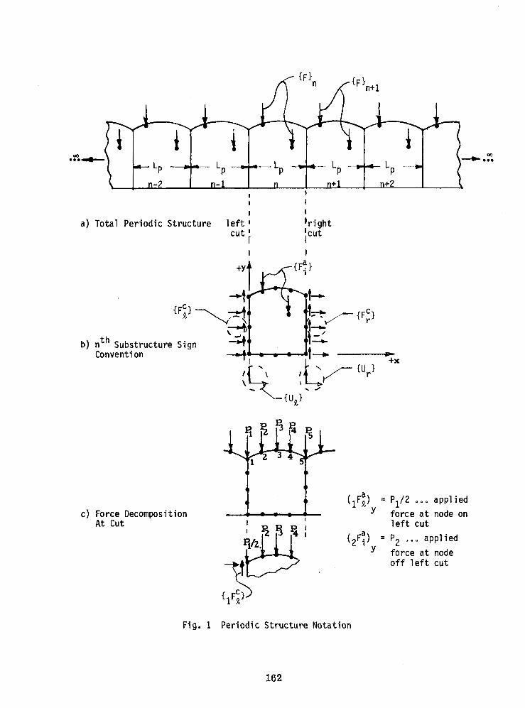
A periodic structure consists of a number of identical substructures,coupled together in identical manners to form the whole system, see for examplefigure la. For such systems, under certain loading conditions, it is oftenpossible to treat only one representative substructure in order to obtain thegeneral response for the whole system. For example, if the loading is exactlythe same for all substructures, the latest (and even some earlier) versions ofNASTRANcan directly solve this class of problem for both static and steadystatecases (i.e., rigid formats 1 and 8). In the case of steady state dynamicsproblems (rigid format-8) involving traveling wave propagation type inputs,there is a slightly more general loading condition on each periodic substruc-ture, namely that the loading on each substructure is identical except for aknown phase constant _o More specifically, the relation between the a_liedforce vector {_}n in the nzn substructure and the one, {-F}n+I in the nTM sub-structure is given by
{T}n+1 : e_ {T}n (1)
where _ is a known phase constant. For the class of problems addressed in thispaper, the phase constant is a purely imaginary constant, i.eo,
= 0.0 + i_* (2)
132

and physicallyrefers to the fact that there is no differenceinenergyloss inprocessingresultsfrom one substructureto the next.
Brillouin(ref. 1) points out that wave motion in periodicsystemshavebeen studiedfor nearly 300 years, whereinphysicistsand electricalengineershave worked in this field in problemareas relatingto optics,crystals,elec-trical transmissionliner, etc. (Elachi,ref. 2, providesa comprehensivelistof 287 referencesin this field). Applicationsof this theory to engineeringstructuralanalysisand solid mechanicstype problemsis only recent. Refer-ences 3, 4, and 5 are typicalof analyticalsolutionsto this type problemforsimple configurationsconsistingof beams, grillagesand plate structures°References6 and 7 representa significantlymore generalapproach to the prob-lem whereintheir applicationof the theory of finite elementsenablesone tosolve a much larger class of problemsinvolvingrather arbitrary structuresthan one could treat by purely analyticaltechniques. References6 and 7appear to restrictthemselvesto the problemof determiningthe conditions(i.e.,values of the steady state responsefreqencym) under which propagatingor non-propagatingfree wave motionwill occur in the absenceof explicitexternaldrivingforces.
In the work presented here, periodic structures with explicit externaldriving forces satisfying Equations (I) and (2) are applied to each substructureas illustrated in Figure la.
If the loadingand spatialboundaryconditionson each substructurearethe same, except for the phase difference, _*, (i.eo, the loading for twotypical points in two neighboring substructures separated by the period lengthLp,are the same except for a multiplying factor of ei_*) it follows that theresponse in each substructure is also the same except for the phase difference_*. A simple example of such a case is a propagating pressure wave passingacross an infinitely long ribbed plate as illustrated in figure 2b (the plate isin air and no air-structure interaction effects are considered). The propagat-ing surface loading wave is given by the formula
p = Poei(kx + mt) (3)
thus the phase difference between any two neighboring substructures is u* = kLp,where Lpis the spatial period of the periodic system, Po is the input loadingpressure amplitude, m is the steady state driving frequency, x is the horizontalspatial coordinate, and k is the wave number of the loading wave.
Other examplesof the phase constantrelativeto a particularexampleareshown in figure 2. In figure 2a, we have a known pressurewave loadingpropa-gating parallelwith the axis of the ribbed cylindricalshell; here, the phaseconstant_* is analogousto the figure2b exampleand needs no furtherexplana-tion. In figure 2c, the incidentwave is incidentat an obliqueangle 0 andis incorporatedinto the formulafor the phase constantgiven in the figure lc.
133

There is a specialcase where the ends of the structuredo not extendtoinfinity(i.e.,the ends never meet) but insteadare connectedcyclically,asin figure 3 for example. For such cyclicalcases, _* must satisfyan addi-tional constraint,namely _* = 2_/n where n = I, 2, 3,..... For example,inthe figure 3 case, n = 8, thus _* = 7/4.
We limit ourselvesto problemshaving "one-dimensionalperiodicity",wherebythis term we imply that only two cuts are needed (we shall refer tothese as the left and right cuts, see figure Ib) to separatethe typicalsub-structurefrom the system. The responsewithin such a substructurecan be,however,multi-dimensional.The remainderof the paper focuseson the proce-dure for obtainingthe displacementand stress responsewithin one typicalblock of the periodicsystem. The typicalsubstructureblock can be made up ofvarious types of structuralelements (includingboth elementswith structuraldampingand nodes with scalardampersattached)containedwithin the NASTRANlibraryof elements(e.g., CQDMEM,CQDMEM1,CBAR, CONROD ... etc.).
SOLUTION FORMULATION
The solutionprocedurepresentedhere is very similarto the one in refer-ence (6), except for the fact that here we are consideringproblemswith expli-cit forcingfunctions. The first step in the solutionprocedureis to "cutout" the typical substructurefrom the overall periodicstructureas illus-trated in figure lb and to subsequentlyreplacethe cut nodes with the internal
forces ({_}n' for the left cut and {_Cr}n for the right cut) that existedatthose nodes beforecutting. The displacementsat the cut nodes are similarlydenotedby {_} and {U } where subscripts_ and r denote left and right and
n r n ththe subscriptn denotesthe n substructure. Since we are only focusingon
the results for the nth substructure,it is convenientto drop the subscriptn from here on for notationalconvenience°
The governingequationsof motion for the substructureare first expressedin the familiarfinite elementform
[M]{_} + [B]{_} + [K]{O'} + {-F} (4)
where [M], [B], [K] are the mass, dampingand stiffnessmatrices of the nthsubstructurerespectively;{_} is the displacementvector of all nodes of the
nth substructure;{_} is the generalizedforce fector; (') z d( )/dt, and barsabove the variabledenote the fact that the variablesare complexand that the
harmonictime responseeimt has not yet been suppressedthus
{_} : {U}ei_t {T} = {F}eimt (5)
134

The next major step is to partition the matrices and vectors of equation(4) into left cut unknowns, right cut unknowns and interior unknowns (subscriptsJ_, r, i refer to left, right and interior respectively and L, R, I refer to thetotal number of displacement component unknowns for the left, right and interiordomain respectively; note due to periodicity, L = R. Thus it follows that afterpartitioning we have
M_I Mj_i IM_,r B_I Bj_i IBj_r
[M] = Mi_ I Mii I Mir [B] = Bij_IBii I Bir- -F - -I .... I- - -I- oMrj_IMri I Mrr Brj_IBri I Brr
I I l I(L+R+I) x (L+R+I)
-K_ IK_iIK_r _
--F --I-- I---1
[K] : Ki_ I Kii I Kir {U}= Ui (6)
Krj_I Kri l Krr UrI I
(1) x (L+R+I)
{_} = o + _i
gc gar r
m
Note the generalized force vectors {F} has been further decomposed as the sum of
an unknown force vector, {_-c}, (which denotes the yet unknown internal forces
existing at the cuts in the structure) and a known applied force vector, {T'a},(which denotes all known forces existing within and at the cuts of the periodicsubstructure).
135
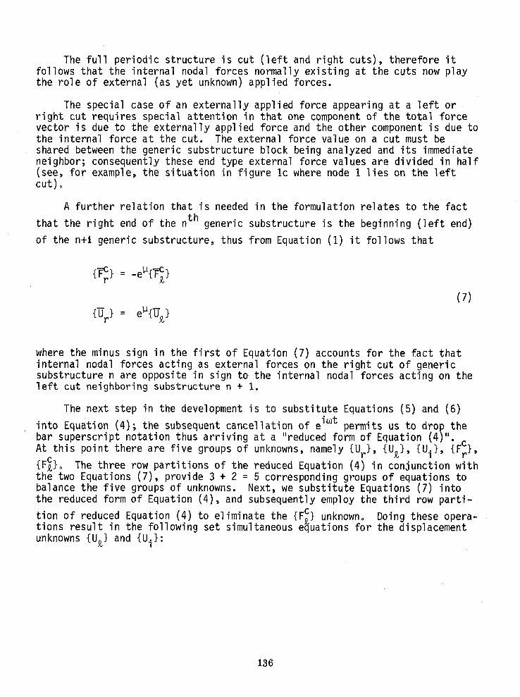
The full periodic structure is cut (left and right cuts), therefore itfollows that the internal nodal forces normally existing at the cuts now playthe role of external (as yet unknown) applied forces.
The special case of an externally applied force appearing at a left orright cut requires special attention in that one component of the total forcevector is due to the externally applied force and the other component is due tothe internal force at the cut. The external force value on a cut must beshared between the generic substructure block being analyzed and its immediateneighbor; consequently these end type external force values are divided in half(see, for example, the situation in figure Ic where node I lies on the leftcut)o
A further relation that is needed in the formulation relates to the fact
that the right end of the nth generic substructure is the beginning (left end)
of the n+i generic substructure, thus from Equation (I) it follows that
{-_r}= -el_{-_ }
(7)
{-Or} = e_{-_}
where the minussign in the first of Equation (7) accounts for the fact thatinternal nodal forces acting as external forces on the right cut of genericsubstructure n are opposite in sign to the internal nodal forces acting on theleft cut neighboring substructure n + i.
The next step in the development is to substitute Equations (5) and (6)
into Equation (4); the subsequent cancellation of eimt permits us to drop thebar superscript notation thus arriving at a "reduced form of Equation (4)".
At this point there are five groups of unknowns, namely {Ur}, {U_}, {Ui}, {F_},{F_}o The three row partitions of the reduced Equation (4) in conjunction withthe two Equations (7), provide 3 + 2 = 5 corresponding groups of equations tobalance the five groups of unknowns. Next, we substitute Equations (7) intothe reduced form of Equation (4), and subsequently employ the third row parti-
tion of reduced Equation (4) to eliminate the {F_} unknowno Doing these opera-tions result in the following set simultaneous equations for the displacement
unknowns {U_} and {Ui}:
136

m
-__2 [MLL]+ I -L°2[MLI]+
ioJ [BLL] + I i_o [BLI] + {U}_ + e-lJ*i{F a][KLL] I [KLI]
l
•, .... (8)-co2 [MIL] + I -_°2 [MII] +
io_ [BIL] + J i_o [BII] + {Ui} {F_}[KIL] I [KIll .
(L+I) x (L+I) matrix (I) x (L+I) vector
where
[MLL]= [Mzz] + Cos]_*[Mcr]+ Cos_* [Mrz] + [Mrr]
[BLL]= [Bzz]+ CosiJ*[B_r] -mSin_* [Mzr]+ (Sin_*/m)[K_r]
+ CosIJ*[Br_]+ [Brr]+ mSinIJ*[MrA]- (Sinp*/m)[Kr_]
[KLL] = [Kzz]+ CoslJ*[Kzr]- mSiniJ*[B_r]
+ CosIJ*[Kr;L] + [Krr] + mSin_* [Brz]
[MLI]= [Mzi]+ Cosu* [Mri]
[BLI]= [B_i]+ Cos_* [Bri]+ mSinI_*[Mri] - (SinlJ*/m)[Kri]
[KLI]= [K_i]+ Cos_* [Kri]+ _SinlJ*[Bri] (9)
[MIL]= [Mi_]+ CosiJ*[Mir]
[BIL]= [Bi_]+ CoslJ*[Bir] - _SinlJ*[Mir]+ (SinlJ*/m)[Kir]
[KIL] = [Kiz]+ Cosl_*[Kir] -mSinl_* [Bir]
[MII] = [Mii]
[BII]= [Bii]
[KII]= [Kii]
At this point, the linear set of complexalgebraicEquations(8) can be solved
for the unknowndisplacements{Uz}, {Ui}. The unknowndisplacementat the
right cut, {Ur} can be easilycomputedwith the secondof equation (7). The
137

size of the algebraic system is governed by the (L+I) x (L+I) coefficientmatrix (i.eo, matrix multiplying the unknown displacement vector) where L+Iequals the number of left cut, L, plus interior, I, unknown displacement com-ponents. Typically I>>L, therefore it is not a very big additional burden onthe equation solver to include the second of Equation (7) as part of the overall
system (actually, we add R extra unknowns, {Ur}, and R extra equations (whereR = number of right cut unknowns). Thus in place of Equation (8), we considerthe slightly larger, but equivalent system of
' _m2 [MLI] + " {F_} +__2 [MLL] + ,I
im [BLL] + , im [BLI] + [0] {U_}
, e-_*i{F_}[KLL] , [KLI]J J .....
__2 [MIL] + __2 [MII] +
i_ [BIL] + i_ [BII] + [0] • {Ui) = {F_} _ (10)
[KIL] [KII]J J .....
I I
i_ [BRL] + I I
, [0] ,[KRR {Ur } {0}[KRL] ,
(L+I+R) x (L+I+R)coefficient matrix
where [BRL]= (sin_*/m)[Iu]
[KRL]= Cos_* [Iu]
[KRR]: -[Iu] (11)
and [Iu] z diagonalunit identitymatrix
The RI block of the displacementcoefficientmatrix in Equation (10) aboveis identicallyzero, thus the bottom R rows of the systemof simultaneousequa-tions are totally independentof the solutionto the top L+I rows° The lengthof the solutionvectorL+I+R is of exactlythe same length of the originalsub-structurematrix (Equations(4) and (6)), consequentlythe modificationof theDMAP instructionsbecomessimplierbecauseof the fact that one need onlyinterceptthe logic of the equationsolver and replacethe existingmass stiff-ness and dampingmatriceswith the modifiedmatrices definedby the new coef-fient matrix of Equation(10) (and associatednew entry definitionsfrom Equa-tions (9) and (11))o Since the length of the solutionvector is still the same
138

as the originalproblembeforemodification,the post processingDMAP opera-tions for displacementprintout,stress recovery,etc. need not be modified.
An alternatescheme (althoughnot yet implemented)would be to modify theinput to the complexequationsolver to accept the smaller (L+I) x (L+I) coef-fient matrix used in Equation(8) directly. After solvingthe smallerL+Ilength displacementvector,the full vector (ioeo,attachingthe missing{Ur}
portion)can be formed by expandingit to length L+I+R via the secondof Equa-tion (7). Finally,stressand displacementresultscan be processedin theusual way with existingDMAP operations.
RIGID FORMAT-8DMAPMODIFICATIONFORNASTRAN
The periodicstructurecapabilitydescribedin the previoussectioncan beimplementedin a standardversionof NASTRAN. In particular,the DMAP sequencerequired to performthe necessaryoperationsare listed in AppendixA. ThisDMAPsequence was checked out on an 1108 computer, standard version of level15.5 NASTRANand is introduced in the EXECUTIVECONTROLdeck with the followinginstructions:
ALTER 138
(see Appendix A for specific instructions)ALTER 139,139
(replace KDD, BDD, MDDwith KDDX, BDDX, MDDXwithin call arguments of FFRDmodule level 15.5see Appendix A for detailed instruction) implementation
ALTER140
(Conditional print statement, see Appendix-A for detailed DMAPinstructions)
These same level 15.5 DMAPinstructions can also be applied to level 17.0NASTRAN,the only difference being that
replace ALTER 138 with ALTER 158
replace ALTER 139,139 with ALTER 159,159
replace ALTER140 with ALTER 160
It is pointed out, however, that the level 17o0 modifications describedabove have not actually been tried although due to the similarity of the change,the DMAPsequence is expected to work.
139

It is important to note that we are modifying the standard NASTRANunknowndisplacement vector coefficient matrix just prior to the entry into the FFRDmodule used for the solution to the simultaneous complex algebraic equations.The implication of this statement is that the row numbering scheme for the dis-placement vector has already accounted for the fact that single point con-straints, multipoint constraints and omitted coordinates have already been
accounted for. Thus, for example, the length of the {U_} vector, L, is notsimply the number of nodes on the left cut times the degrees-of-freedom pernode, but rather is less by the amount corresponding to the number of SPC's,MPC_sand OMIT's relating to the nodes along the left CUto Similar commentsapply to the lengthof the {Ui} and {Ur} vectors. The understandingof the
above displacementvector lengthcommentsmust be clearly understoodby theuser before attemptingto fill out the input data matrix partitioningvectorsCVIO0, CV01O, CVO01 definedlater in this paper.
INPUT DATAFORNASTRANRUN
The BULK DATA input to a typical periodicstructurerun consistof twobasic parts. The first part correspondsto the usual bulk data input cardsnormally requiredto make a NASTRANrun (e.g.,GRID CARDS, ELEMENTCARDS, DAREACARDS, FREQ CARD, DLOAD CARD, etc.); the second part consistsof specialinputcards that are explainedin the followingtext.
PARAMCards
These cards are used to enter variousmatrix coefficientsappearinginEquations(9) and (11); especiallythe constants
Text Variable ComputerVariable
Cosu* _ CMST
0.0 + i_ _ FI#VMEG
._2 _ N_MEG2
-I.0 _ N#NE
-sin_*/m _ NSMSB_ (12)
-(sin_*)m _ NSMST_
+i.0 _ P#NE note: 0 = zero
sin_*/m z SMSB_ # = letter
(sin_*)m _ SMST#
140

are read in on standardNASTRANPARAM cards where IJ*is the phase angle definedin Equation (2) and _ is the angulardrivingfrequencyin radiansper second
(m = f.2_ where f = driving frequencyin Hz specifiedon the FREQ card). Theformat for a typicalPARAM card is:
Col's I - 8 PARAM
Col's 9 - 16 one of the 8 computervariablenames definedbyEquation(12)
Col's 17 - 24 real part of variabledefined in Col's 9-16
Col's 25 - 32 imaginarypart of variabledefined in Col's 9-16 (onlynon zero entry is for variableFI_MEG)
Comments
Strictly speaking, the real part of variable FI_MEGshould be 0.0; however,for the NUSCUnivac 1108, operating with the level 15.5 version of NASTRANusedto implement the procedure, an arbitrary small number if entered (say 1.0xlO -2°)in order to avoid a strange system type error message that is printed whenexactly 0.0 is entered as the real part. The FI_MEGvariable is only used tocompute and subsequently print out the internal forces at the cuts after allthe main calculations for displacement are completed. The mentioned error mes-sage probablywill not appear iF other NASTRANversionsand/or other computersystemsare used.
DMI Cards for Matrix Partitioning
A set of DMI directmatrix input cards are needed to providethe informa-tion NASTRAN needs to partitionthe mass, dampingand stiffnessmatrices.Three groupsof cards are needed;a column partitioningvector for the left cutgroup of displacementnode components,CVIO0;a column partitioningvector forthe interiorgroup of displacementnode components,CV010; and a columnparti-tioning vector for the right cut group of displacementnode components,CVO01.A set of row partitioningvectorsare automaticallygeneratedby the AppendixADMAP instructions. The column partitioningare made up of entries that areeither 1.0 or 0.0. Since all entrieswithin NASTRANare assumedto be zero
unless otherwisespecified,the user need only enter 1.0 values in the appro-priate slot in each of the above mentionedpartitioningvectors. The rules aresimple and are as follows:
° Formationof left cut partitioningvector CVlO0
Enter a 1.0 in each row number correspondingto each active indepen-dent componentdegrees-of-freedomlying along the left cut. Thelength of the CVIO0 vector is L+I+R and there should be L 1.0 entries(the remainingI+R entriesare automaticallyzero by virtue of not
141

being defined). If the left cut nodal numbering pattern is sequentialand starts with the lowest node number of the whole system (e.g., nodeI, 2, 3 .), then the first L entries of CVIO0 will be all 1.0values.' However, if the left cut numbering scheme does not containonly the lowest node numbers, but instead the whole system is num-bered at random, then the L 1.0 entries will correspondingly be dis-tributed throughout the CVIO0 vector, and the "bookkeeping" involvedwith defining the CVIO0 vector becomes messy° The user having MPC's,SPC's or OMIT's applied to nodes along the left cut must be sure toaccount for these during the process of entering the 1.0 values intothe partitioning vector CVIO0.
• Formation of the interior partitioning vector CVOIO
Enter a 1.0 in each row number corresponding to each active indepen-dent component degree-of-freedom lying on the interior of the struc-ture. The length of the CVOIOvector is L+I+R and there should be I1.0 entries (the remaining L+R entries are automatically zero). Ifthe interior nodes are numbered sequentially, (following the samesequential pattern used in the CVIO0 vector), then the middle L+I,L+2, . . . L+I entries of the CVOIOvector will all be 1.0 values.Again remember to account for SPC's, MPC's and OMIT's in the number-ing scheme.
• Formationof the right cut partitioningvector CVO01
Enter a 1.0 in each row number correspondingto each active indepen-dent componentdegree-of-freedomlying pn the right cut of the peri-odic structure. The length of the CVO01 vector is L+I+R and thereshould be R 1.0 entries (the remainingL+I entriesare automaticallyzero). If the left cut, interior,and right cut nodes are all num-bered sequentially(in the respectiveorder mentioned),then the end-ing L+I+I, L+I+2, . . L+I+R entriesof the CVO01 vector will all be1.0 values. Again r_memberto accountfor SPC's, MPC's and OMITS'sin the numberingscheme.
DMI Cards Format
The bulk data cards for the definitionsof the partitioningvectorsviathe standardDMI cards is as follows:
• CVIO0 vector cards
CoI's Ent_vfirst header card
1-8 DMI9-16 CVO0117-24 0
142
Col ' s Entry
25-32 233-40 I41-48 I49-56 blank57-64 integer value equal to magnitude of (L+R+I)65-72 1
second card
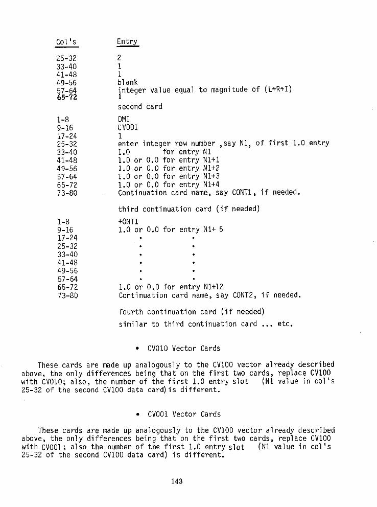
I-8 DMI9-16 CVO0117-24 I25-32 enter integer row number ,say N1, of first 1.0 entry33-40 1.0 for entry NI41-48 1.0 or 0.0 for entry NI+I49-56 1.0 or 0.0 for entry N1+257-64 1.0 or 0.0 for entry NI+365-72 1.0 or 0.0 for entry NI+473-80 Continuation card name, say CONT1, if needed.
third continuation card (if needed)
1-8 +ONT19-16 1.0 or 0,0 for entry NI+ 517-24 • •25-32 • •33-40 • •41-48 • •49-56 • •57-64 • •65-72 1.0 or 0.0 for entry N1+1273-80 Continuation card name, say CONT2, if needed.
fourth continuation card (if needed)
similar to third continuation card ... etc.
• CV010Vector Cards
These cards are made up analogously to the CVIO0 vector already describedabove, the only differences being that on the first two cards, replace CVIO0with CVOIO; also, the number of the first 1.0 entry slot (NI value in col's25-32 of the second CVIO0 data card) is different.
• CVO01Vector Cards
These cards are made up analogously to the CVIO0 vector already describedabove, the only differences being that on the first two cards, replace CVIO0with CVO01; also the number of the first 1.0 entry slot (NI value in col's25-32 of the second CVIO0 data card) is different.
143

Finally, examples of making the partitioning cards is given later in ademonstration problem.
DMI Cards for Merge Operations
A set of DMI direct matrix input cards are needed to define certain dum_vmatrices which NASTRANneeds to successfully merge certain internal
matrices within the Appendix-A DMAPsequence° These input cards will consistof a group of eight cards that must always be included for a run. The onlything that changes from one NASTRANrun to another is the lengths of thesedummy arrays. These dummy null arrays are only introduced to avoid DMAP errormessage printouts for Univac 1108, level 15.5 NASTRANthat occurred when thelead matrix entry in the standard DMAPMERGEoperation is not defined.
DMI Cards Format
Col's Entry
first header card
1-8 DMI9-16 LIXLI enter characters, _oes not mean multiDly LI times LI)17-24 025-32 233-40 141-48 149-56 blank57-64 enter integer equal to L plus I65-72 enter integer equal to L plus I
second card
1-8 DMI9-16 LIXLI17-24 125-32 133-40 O. 0
third card
same as first card, except
Col's 9-16 enter LIXL2Col's 57-64 enter integer equal to L plus ICol's 65-72 enter integer equal to L plus L
fourth card
same as second card, except
Col's 9-16 enter LIXL2
144

fifth card
same as first card, except
Col's 9-16 enter L2XLICol's 57-64 enter integerequal to L plus LCol's 65-72 enter integerequal to L plus I
sixth card
same as second card, except
Col's 9-16 enter L2XLI
seventh card
same as first card, except
Col's 9-16 enter L2XL2Col's 57-64 enter integerequal to L plus LCol's 65-72 enter integerequal to L plus L
eighth card
same as second card, except
Col's 9-16 enter L2XL2
DMI Cards for Unit Matrix Definition
Finally, a set of DMI direct matrix input cards as needed to define theunit matrix [I u] employed in Equation (11).
DMI Cards Format
Col's Entr____yy
first header card
I-8 DMI9-16 UMATR17-24 025-32 633-40 i41-48 249-56 blank57-64 enter integer equal to L plus L64-72 enter integer equal to L plus L
145
Col ' s Entry
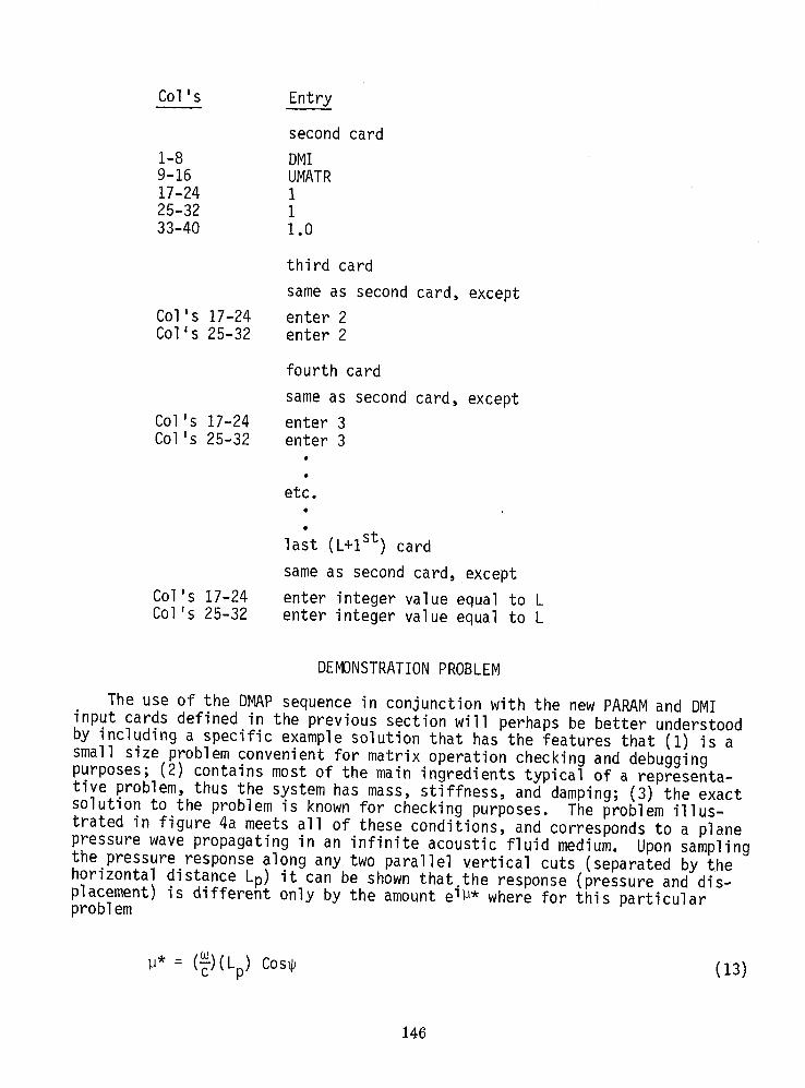
second card
I-8 DMI9-16 UMATR17-24 125-32 133-40 1.0
third card
same as second card, except
Col's 17-24 enter 2Col's 25-32 enter 2
fourth card
same as second card, except
Col's 17-24 enter 3Col's 25-32 enter 3
etc.
last (L+I st) card
same as second card, except
Col's 17-24 enter integer value equal to LCol's 25-32 enter integer value equal to L
DEMONSTRATIONPROBLEM
The use of the DMAPsequence in conjunction with the new PARAMand DMIinput cards defined in the previous section will perhaps be better understoodby including a specific example solution that has the features that (i) is asmall size problem convenient for matrix operation checking and debuggingpurposes; (2) contains most of the main ingredients typical of a representa-tive problem, thus the system has mass, stiffness, and damping; (3) the exactsolution to the problem is known for checking purposes. The problem illus-trated in figure 4a meets all of these conditions, and corresponds to a planepressure wave propagating in an infinite acoustic fluid medium. Upon samplingthe pressure response along any two parallel vertical cuts (separated by thehorizontal distance Lp) it can be shown that the response (pressure and dis-placement)is differentonly by the amount ei_* where for this particularproblem
M* = (_)(Lp) Cos_ (13)
146

where m = driving frequency (rad/sec), Lp = length (in.) between two parallelcuts, c = compressional wave speed (in/sec); _ = angle of incident wave. Thesolution for the pressure and motion response is sought_for the shaded regionshown in figure 4ao Only the dotted outlined region is modeled with finiteelements and is correspondingly shown in figure 4bo
In order to exercise this demonstration problem to the fullest extent, wewill use different types of boundary conditions on all four sides of the fig-ure 4b finite element model.
Boundary Conditions
• Left and right vertical cuts
Since this problem falls within the class of problems solvable bythe phase difference type boundary condition, boundary conditionsspecified by Equations (7) are enforced. Here the left and rightcut forces and displacements are taken as unknowns°
• Top face
The boundary condition for the top face is different from the leftand right face in that here we explicitly apply the free field pres-sure (converted into equivalent nodal forces). The formula for thefreely propagating pressure wave is given by the expression
i(kr) imtp(x,y,t) = poe e (14)
where k = _/c = wave number (in. -1)
r = spatial coordinate normal to direction of wave propagation (ino)
Po = steady state pressure amplitude (psi)
i = _-1
p = pressure (psi) (spatial variation)
and r is related to the x,y coordinates by the relation
r = x cos_ + y sin_ (15)
The y-direction force at upper face node 3 is computed by substitutingp(x,H) from Equation (14) into the expression
X=Lp/4
(3F_)y =/- p(x,H) dx (16)x:O
147
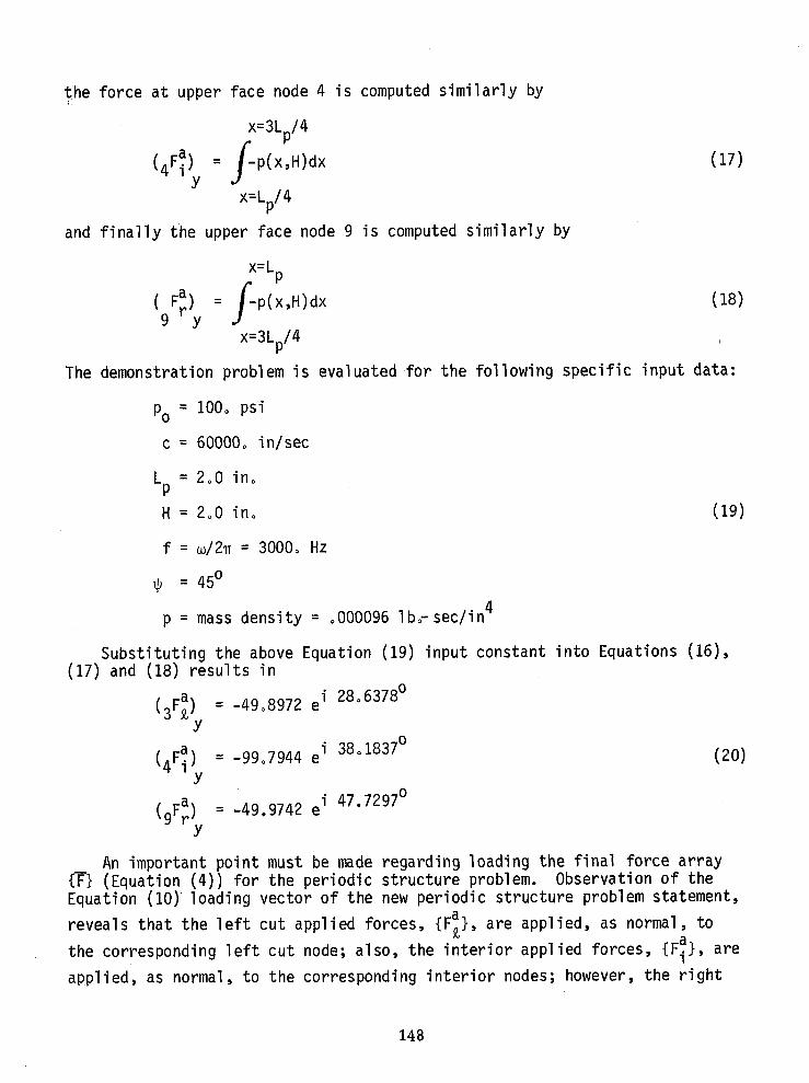
the force at upper face node 4 is computedsimilarlyby
x=3Lp/4
(4F_ = f-p(x,H)dx (17)
X=Lp/4
and finallythe upper face node 9 is computedsimilarlyby
X=Lp
(F_) = f-p(x,H)dx (18)9 y
x=3Lp/4
The demonstrationproblemis evaluatedfor the followingspecific input data:
Po = 100o psi
c = 60000° in/sec
Lp = 2°0 ino
H = 2°0 ino (19)
f = m/2_ = 3000° Hz
= 45o
p = mass density = °000096 Ib_sec/in 4
Substituting the above Equation (19) input constant into Equations (16),(17) and (18) results in
i 28°6378o(3F_}. = -49°8972 e
Y38o1837o
(4F_). = -99°7944 ei (20)Y
i 47.7297 o_9F_).= -49.9742e
Y
An importantpoint must be made regardingloadingthe final force array{_} (Equation(4)) for the periodicstructureproblem. Observationof theEquation(10) loadingvectorof the new periodicstructureproblemstatement,
revealsthat the left cut applied forces,{F_}, are applied,as normal, to
the correspondingleft cut node; also, the interiorappliedforces, {F_},are
applied,as normal,to the correspondinginteriornodes; however,the right
148

cut appliedforces,{F_}, are not appliedto the right cut nodes, but rather,
are first multipliedby the complexconstante"_*i, and then applied to thecorresponding,left cut node° For the demonstrationproblemat hand, substi-tuting Equation (19) into Equation(13) impliesthat _* = 25°455840, thus
a ei22o27387 °ei_* (9Fr) = -49°9742 (21)
Y
therefore,in summary,at node number 3 in the y directionapply a net sum
force = -49°8972e i28°6378° -49°9742 e i22°27387° (22)
and at node number4 in the y directionapply a net
force = -99°7944ei38"1837° (23)
and at node number 9 in the y directionapply a net
force = 0o0 (i.e.,do not apply any force)°
• Bottom face
The boundary condition for the bottom face could have been selectedsimilar to the top face (i.eo, we convert the pressure into equiva-lent nodal forces). However, instead we use a slightly more compli-cated boundary condition that permits us to introduce a [B] matrixentry into the problem° More specifically,the pressureand normalvelocityalong the bottomcut can be obtainedfrom the expression
p(x,o) = _V n (24)
where Vn is the particlevelocity normal to the wavefront propagation direc-
tion. Therefore the relation between the Vy velocity component and the ydirection resisting reaction is given by
(F_) _ (p(x,o).AA)= pc_a Sin_ Vy (25)y
damping
constant_Cd
Thus, the bottom face boundarycondition(simulatingan approximatewaveabsorbingboundarycondition)is achieved by placingviscousdampersalongthe bottom cut (see figure4b), whereinthe damper constantsare definedby
Cd = pcAA Sin_ (26)
where AA is an appropriatearea factor relatingthe pressureand concentratedforce
(FI) . When the wave lengthof the incidentwave is long relativetoY
149

the mesh size, one can set AA = the surface element length for bottom surfacenodes off the cuts and set Z_A= 1/2 the surface element length for the nodeslying on the cuts° Thus for the demonstration problem at hand, Cd = 8.14587
for the middle damper and half that amount for the end cut dampers°
Preparation of DemoNASTRANInput Data
• executive control
The form of the DMAPinstructions presented in Appendix A are general andare not problem dependent° The only times the user deviates from the presentedDMAPsequence is (I) when he switches from one level of NASTRANto anotherwherein the ALTER Statement numbers change; or (2) when he wishes to turn offor turn on the intermediate matrix printout switch ISW, defined in the thirdDMAPALTERstatement (ISW = +I prints all intermediate matrix operation stepsin addition to a printout of the FORVECvector which lists the left cut,interior, and right cut nodal forces; ISW = -i no intermediate printout)°
° case control
The standard CASECONTROLdeck is shown in the APPENDIXA, wherein theonly thing worth no_ing is the fact that a DLOADcard is used for the purpose
of superimposing the two vectors {F_} and e-_*i {F_} which are both applied to
the same left cut nodes (in correspondence with the first partition of Equa-tion (10))o
• bulk data
The CDAMP2cards are used to define the damping constants applied at thebottom surface nodes° The CQDMEMmembrane elements (and corresponding MAT2,PQDMEMcards) are used to define the fluid media, employing the displacementfluid element approach described in refo8. The collection of DLOAD,DAREA,DPHASE,RLOADI, TABLEDI cards are used to insert the applied forces defined byEquations (22) and (23). The GRDSETcard is employed to eliminate the non-applicable 3, 4, 5, 6 degrees-of-freedom for the 2-D membraneelements° Stand-ard GRID cards define node coordinates and the standard FREQcard defines fre-quency of f = m/2_ = 3000 Hz. The special Dine PARAMcards defined by Equations(12) are evaluated using the data in Equations(19)o In the case of the DMIcards for the partitioning vectors CVIO0, CV010, CVO01, the first thing toestablish for the problem is the sizes L, R, I for the individual partitions.It is convenient, for bookkeeping purposes, to number the left cut sequen-tially; and to also number the interior sequentially (with the lowest interiornode number appearing next to the highest left cut node number) and finallynumber the right cut sequentially with the lowest right cut node appearing next
150
• to the highest internal node number° Thus for the problem at handt, L = 2degrees-of-freedom/node times 3 left cut nodes = 6; I = 2 degrees-of-freedom/node times 3 interior nodes = 6; and R z L = 6 due to the periodicity of thestructure° The first 6 entries of CVIO0 are 1.0, the rest of the entries arezero; the 7th through 12th entries of CVOIOare 1o0, the rest being zero; andfinally the 13th through 18th entr_es of CVO01are 1.0, all other entries beingzero° The 8 merging DMI cards LIXLI ... L2XL2 are defined according to theinstructions given earlier in the paper and need no further comment° Finallythe unit matrix DMI cards for the UMATRmatrix are defined according to theinstructions given earlier in the paper°
Results of NASTRANDemoProblem
Selected output results for the figure 4b demonstration problem are pre-sented as NASTRANdirect printout (real and imaginary part type output format)in APPENDIXB. The first part of the NASTRANprintout illustrates the netinput vector (e.go,resultsof Equations_2,)and _3-));it is always good toincludeas a checkingfeatureof the input.
Next the stress output is printedand refers to the stress computedat thecenter of the element. Note that due to the sign conventiondifferenceregard-Ing-_ress and pressure (oppositein sign, see refo 8 for details),the usermust reversethe sign of stress to obtain the pressure,ioeo,
P = -_xx -Oyy
It should be noted that the NASTRANoutput format headings are in error(due to a formating bug in NASTRANthat has remained in practically all levelsof NASTRAN);the output heading should be read as follows (for each element row
of stressoutput):Real Pto (OXX),Real Pt_-(_yy),Real Pto (axy),Imgo Pt. (_xx),
Img. Pt. (Oyy), Imgo Pto (Oxy)O The resultsshown in APPENDIXB, Table B-l,show the NASTRAN resultsnext to the exact solution,after converting,the realand imaginaryparts into amplitudeand phasedata.
The exact solutionis evaluatedwith p(x,y) from Equation (14) at distancesr that locatea l:ine(drawnparallelto the wave front) which passes throughthemidpointof an element. The NASTRANresultsagree quite well with the exactsolutionin both phase and amplitude° It is noted that avery slight asymmetryexists betweenthe NASTRAN phase angle resultsfor element3 and element4°This is probablydue to the fact that the boundaryconditionson the%Dpandright cut surfacesdo not result in exactlythe same appliednodal forces (eog.,the top forceswere not computedusing a consistentpressure-to-forceapplica-tion formulathat involvesthe displacementshape functions). A similarcom-ment appliesto the relationbetweenthe bottom surface forcesand left cut
?Suppose,for illustrativepurposes,node 5 had the x displacementSPC con-strainedto zero and supposethe x displacementof node 4 was forced(throughan MPC relation)to equal the x displacementof node 6. In this particularcase L = 2.3 = 6; I = 2.3-1-1 = 4; R z L = 6°
151
forces° When the programis run with the detailedprint switch triggered(ISW = +1), the left and right cut forcesare computedfrom the solutiondis-placementvectorand subsequentlyprintedin condensedformat {underthe FORVECheader). Inspectionof these resultsshowed that correspondingleft and rightcut internalnodalforces differedby the properamount,_* = 25.4550.
CONCLUDINGREMARKS
The DMAPsequence presented in APPENDIXA, permits the NASTRANuser tosolve a class steady state dynamically loaded periodic structures, wherein theinternal forces and resulting response at the periodic ends of the typical
repeating substructure are related by a known complex phase relation, ei_*.The DMAPsequence is general and need not be changed from one problem to thenext. When using the methodology presented here, one should be extremely care-ful that the CVIO0, CVOIO, CVO01partitioning vectors are prepared properly.For large problems, a preprocessor should be written which automatically gen-erates these vectors° One should also be careful to allow for SPC, MPCandOMIT cards which compact the solution vector and consequently should be takeninto account in the preparation of the partitioning vectors. The user isstrongly advised to study the sample demonstration problem presented herebefore undertaking anymore complicated problems.
At this point, the DMAPsequence has been checked out for a set of smallsize problems, therefore comments regarding computer run time on large problemscannot be made at this time. Someof the DMAPoperations can be increased inefficiency by employing the matrix operation ADD5DMAPmodule in place ofrepeatedly employing the matrix ADDDMAPmodule° The ADD5routine was notused in the 1108, level 15o5 version of NASTRANdue to the fact that the systemdid not consistently successfully add a string of 5 matrices during certaincheckout phases of the programming.
Finally, it is advised that before attempting to exercise the DMAPsequencepresented in APPENDIXA, one should run the demonstration problem as a benchmark check ino If a Univac 1108, level 15.5 version is used, it may be necessaryto increase the "max-files" to 40 in NTRAN$.
REFERENCES
1o Brillouin, Lo, "Wave Propagation in Periodic Structures", Dover Publica-tions, Inc., New York, 1946o
,
2. Elachi, C., "Waves in Active and Passive Periodic Structures", Proceedingsof the IEEE, Vol. 64, NO° 12, Dec° 1976o
3o Heckl, Mo Ao, "Investigations on the Vibrations of Grillages and OtherSimple BeamStructures, Journal of the Acoustical Society of America,Volo 36, 1964o
152

4o Abrahamson,A. L., "FlexualWave Mechanics- an AnalyticalApproach to theVibrationof Periodic StructuresForced by ConvectedPressure Fields",Journal of Sound and Vibration,Vol. 28, 1973.
5. Murakami,H. and Luco, E., "Seismic Responseof a Periodic Array of Struc-tures",Journal of the EngineeringMechanicsDiv., ASCE, Oct. 1977o
6o Mead, Do J., "A GeneralTheory of HarmonicWave Propagationin LinearPeriodicSystems with Multiple Coupling",Journalof Sound and Vibration,VOlo 27, No. 2, Feb. 1973o
7. Orris, Ro M. and Petyt, M., "A Finite ElementStudy of Harmonic Wave Pro-pagation in PeriodicStructures",Journalof Sound and Vibration, VOlo 33,NOo (2), Feb° 1974o
8. Kalinowski,Ao Jo and Patel, J. S., "A Summaryof NASTRAN Fluid/StructureInteractionCapabilities,NASTRAN Users' Experiences",Fifth Colloquium,NASA TM X-3428,Oct. 1976o
153

APPENDIX-A
(NASTRANDEMONSTRATIONPROBLEMINPUT)
NASTRAN EXECUTIVE cONTROL DECK
ID NUSC PERIODIC STRUCTURE SAMPLEAPP DISP
SOL 8wnTIME 30DIAG 2p3pBp14f15DIAG 22ALTER t38
$ DMPA INSTRUCTIONS FOR PERIOnIC STRU_TUn_ (_nn_n BY a.J:_ALIMnW_Kt}$ ISW=+I PRINT ... =-I NO PRINT OF ALL KEY MATRICES FOR PERIODIC STR.
PARAM //C,N,NOP/V,N,ISW:+I $PARAM //C,NpNOP/VIN,IMI:-I $PARAM t/¢,NpNOPtVeNpPURSWi:-I $$ DEFINE ROW PARTITIONING VECTORS WITH DUMMY ADD OPERATION$ WHERE CV100 CVOI_ CVO01 ARE RFA_ IN _N DMT BUlK DATAADD CVIO0p/RVIO0 $ADD CVO10p/RV010 $ADD CVOO1,/RVO01 $COND MAReISW $MATPRN RVlOOpRVOlOpRVO01,p// $
MATPRN CVIO0tCVOIOpCVOOtpP// $LABEL MAR $$ CONDITIONAL PRINT OF KDDpMDD, BDO BEFORE PARTITION APPLIED (COND KALpISW $MATPRN KDDpMDDpBDDpo// S$ SAVE.ORIGINAL KDD MDD BDD MATRICES FOR pROCESSING FORCES AT CUTSADD KDD_/SAVKDD $ADD MOD,/SAVMDD $ADO BDD,/SAVBDD $LABEL KAL$$ PARITION KpM,B MATRICES$ PARTITION LL BLOCKPARTN KDD,CVZ00,RVIQO/pptDKLL/¢pNp_ $PARTN MDDpCVIOOoRV100/,ppDMLL/CpNpl $PARTN BDDpCVIOOwRVIOO/ppPDBLL/CpNpl $$ PARTITION LI BLOCKPARTN KDDoCV01OoRV_O0/tttDKLI/CtNol $PARTN MDDpCV010,RVlqO/pppDMLI/CtNpl $PARTN BDDwCVOIOpRVIOO/PpPDBLI/CpNpl $$ PARTITION LR BLOCKPARTN KDDpCVOOlwRVIO0/pppDKLR/CwNpl $PARTN MDDpCVO01,RV100/_DMLR/C,N*I $PARTN BDD_CVOOI_RVI00/_*DBLR/C_N_I $$ PARTITION IL BLOCKPARTN BDD,CVIOOpRVOIO/,_DBIL/CeNf_ S
15_

l_ KDDpCVIOO,RV0101Pp_DKIL/CpN_I
PARTN MDDpCVIOOtRVOEOIwppDMIL/CpNpl $$ PARTITION II BLOCKPARTN _DDtCVOI0,RVO10/pPPDKII/C,Npl $PART_ MDD,CVOIO,RVOIO/,w3DMII/C,N,I $
PARTN BDOPCVOI0,RVO10/ptpDBII/C,Npl $$ PARTITION IR BLOCKPARTN KDDpCVOOI_RVOI0/_p_DKIR/CpNtl $PARTN MDO_CVOOIoRVOIO/pppDMIR/CpNpl $PARTN BDDpCVOOI,RVOIO/PwpDBIR/C,Npl $$ PARTITION RL BLOCKPARTN KDDp CVIO0, RVOOI/PppDKRL/CpNpl $PARTN MD_P CVl00t RVO01/,ppDMRLICpN,I $PARTN BDO, CVl0Ot RVOOI/_tpDBRL/CwN,I $$ PARTITION RI BLOCK
PARTN KCO,CVOIO,RVOOI/,,,DKRI/C,N,IPART,_ MGD,CVOIO,RVOOI/,,,DMRI/C,N,IPARTIJ BDDpCVOID_RVDOI/pp,DBRI/CwN,I S
PARTITION RR F_LOCK
PARTN KDDt CVO01, RVOOI/p,wDKRR/CpNpl $PARTN MDDt CVOOIp RVOOt/,p_DMRR/CpNpl $PARTN BDD, CVO01, RVOOI/ppPOBRR/CpN,I $$CONDITIONAL PRINT OF PARTITIONSCOND KALIN,ISW $MATPRN DKLLpDMLLpDBLL,P// $MATPRN DKLItDMLIwDBLI,t// $BATPRN DKLRPDMLRpDBLRp,// $MATPRN DKILpDMILpDBILt_// $MATPRN DKII,DMII_DBII_,// $
MATPRN DKIR,DMIR_DBIR_// $NATPRN DKRL,DMRL_DBRL_,// $MATPRN DKRI_DMRI,DBRI_// $MATPRN DKRR,DMRR_DBRR_// $LABEL KALIN $$
$ FORM PARTITIONS OF ASSEMBLED MATRIX MDDX_ BDDX, KDDX
$ FORM LL BLOCK$$ FORM AMLLADD DMLL_DMLK/DIAMLL/V_Y_PONE/V_Y,CMST $ADD DIAMLL,DMRL/D2AMLL/V_Y_PONE/V,Y_CMST $ADD D2AMLL,DMRR/AMLL/V_Y_PONE/V_YoPONE $PURGE KDD_MDD_BDD/PURSWt $
-- PURGE DtAMLL_D2AMLL/PURSWl $
155

$ FORM ABLL
ADD DBLLPDBLR/DIBLL/VpYfPONE/VpYpCMSTADD DIBLLIDMLR/D2BLL/VpYpPONE/V_YpNSMSTO $
ADD D2BLLpDKLR/D3BLL/VwYpPONE/V_YpSMSB 0 $.ADD D3BLL,DBRR/D4BLL/VpYpPONE/VpYpPONE
.PURGE DIABLLpD2ABLL,O3A.BLL/PURSWl $ADD D4BLLwDMRL/DSBLL/VpY_PONE/V_YPSMSTO
___OO DSBLLt__KRLIABLL/VtYfPONE/V,YpNSMSB_ $PUR@E D_BLLpD5BLL/PURSWl $$ FORM AKLL
ADD DKLLw_KLR/DIKLL/VpYPPONE/V,YpCMST $ADD DIKLLPDBLR/D2KLL/VwYpPONE/VpY°NSMSIO 5ADD 02KLLpDKRL/D3KLL/VpYpPONE/VpY_CMST $ADD D3KLLpOK.RR/D4KLL/VpYpPONE/VpY,PONE $
ADD OWKLLpDBRL/AKLL/VpYwPONE/VpYwSMSTO $PURGE DIKLLwO2KLL,D3KLLwDWKLL/PURSWl $$ FORM LI BLOCK$
$ FORM AMLIADD DMLIpDMRI/AMLI/VpYpPONE/VpYpCMST $$ FORM ABLI
ADD DBLIpDBRI/OIBII/VpYpPONE/VpYwCMST $ADD DIBLIwDMRI/D2BLI/VpYpPONE/VpYpSMSTO $
ADD D2BLIpDKRI/ABLI/VpYpPONE/V,YtNSMSBO $PUR@E DIBLIpQ2BLI/PURSWl $$ FORM AKLI
ADD DKLIpDKRI/DtKLI/V_YpPONE/VpYwCMST $ADD DIKLItOBRI/AKLIIVoY_PONE/V,Yw_TO $PURSE DtKLI/PURSWt $$ FORM IL BLOCK$
$ PORM AMILADD DMIL_DMIR/AMIL/V_Y_PONE/V_Y_CM_T $
___._._$ FOR_ AOI_ADD OBIL_DBIR/DtBIL/V_Y_PONE/V_Y_CMST $ADD DIBIL_OMIR/D2BIL/V_Y_PONE/V_Y_NSMSTO $ADD D_BIL,OKIRIABILIV_Y_PONE/V_Y_SMSBO $PURSE DIBIL_O_BIL/PURSWt $$ FOR_ AKILADD DKIL,DKIR/DtKIL/V_Y_PONE/V_Y_CMST $ADD DSKIL_OBIRIAKILIV_Y_PONE/V,Y_NSMSTO $PUR@E DIKIL/PURSWl $$ FORM II BLOCK
$ AMII SAME AS DMII ABII SAME AS OMII AKII SAM_ AS DKII$ FORM RL BLOCK
156

ADD UMATR_/ABRL/VpYpbMSBU $
ADD UMATR,/AKRLIVpYtCMST $$ FOHM RR BLOCKADD UMATRt/AKRR/VpYtNONE $
$ THE LR w IR oRl BLOCKS ARE NULL$ PRINT BLOCKS BEFORE ASSEMBLYCOND DEBtISW $MATPRN AMLLpABLLpAKLLp,// $
MATPRN AMLIpABLIpAKLI_p// $MATPRN AMILPABILpAKILPp// $
MATPRN ABRLpAKRL_AKRRp_// $PRTPARM //CpNpO$LABEL DEBS$ •
$ NEXT ASSEMBLE BLOCKS WITH MERGE$ •$ MERGE LL BLOCKMERGE LIXLIpPpAKLL_CVlOOtRVIOO/KDDXLL/CwNpt SMERGE LIXLIpppAMLL_CVIOOpRVIOO/MDDXLL/CpNpt $MERGE LIXLIpppABLLoCVtOOpRVZOO/BDDXLL/CpN_t $$ MERGE LI BLOCK
MERGE LIXL2ppPAKLIpCVOIOtRVtOO/KDDXLI/CPNpl $MERGE LIXL2PttAMLI_CVOIOpRVIOn/MDDXLI/CpN,t $MERGE LIXL2ptpABLIpCVOIOpRV%OO/BDDXLI/CpNet $$ FORM PARTIAL SUMADD KDDXLLpKDDXLI/SUMKI $ADD MDOXLLwMDDXLI/SUMMI $ADD BDDXLLpBDDXLIISUMBI $
$ PURGE COMPONENTS OF PARTIAL SUM NOT NEEDED ANY MOREPURGE KDDXLLtKDDXLIpMDDXLLpMDDXLIpBDDXLLoBDDXLI/PURSWl $$ MERGE IL BLOCKMERGE L2XLIPtPAKILpCVIOOtRVOIO/KDDXIL/CpNwt $MERGE L2XLIpppAMILPCVIOOpRVOtO/MDDXIL/CPN_I $MERGE _XLIwppABILpCVIOO_RVOIO/BD_XIL/C_N_I $$ CONTINUE PARTIAL SUMADD SUMKI_KDDXIL/SU_K2 $ADD SUMMt_MDDXIL/SUMM2 $ADD SUMBI_BDDXIL/SUMB2 $COND JOHN_ISW SMATPRN SUMKI_KDDXIL_SUMK2_SUMMI_MDDXIL//SMATPRN SUMM2_SU_BI_BDDXIL_SUMB2_/I$LABEL JOHN $$ PURGE COMPONENTS OF PARTIAL SUM NOT NEEDED ANY MOREPURGE SUMKt_KDDXIL_SUMMI_MDDXIL_SUMBI_DDXIL/PURSW1 $
$ MERGE II BLOCK
157
MERGE L2XL2,p,DKII_CVOIOpRVOZO/KDDXII/CpN,1S
MERGE L2XL2,,,DMII,CVOIO,RVOIO/MDDXII/C,Nwl $MERGE L2XL2,,,DBIItCVOIOpRVOIO/BDDXII/CwNpt $S CONTINUE PARTIALSUMADD SUMK2,KDDXII/SUMK3 $ADD SUMM2,MDDXII/MDDX S
$ WHERE MDDX IS THE FINAL MASS MATRIX SUMADD SUMB2pBPDXII/SUMB3 $COND BULL, ISW $
MATPRN _UMK2,KOnXtI.SUMK3.SUMM_,M_n_III/_MATPRN MDDXPSUMB2,BDDXII,SUMB3,//$LABEL BULLS
S PURGE COMPONENTS OF PARTIAL SUM NOT NEEDED ANY MOREPURGE SUMK2pKDDXII,SUMM2PMDDXII,SUMB2,BDDXII/PURSWl S$ MERGE RL BLOCKMERGE ITXLI_poAKRL_VI_B_RVOOIIKDnWRi ICIN.I }MERGE LIXLIpp,ABRLwCVIOOpRVOO1/BDDXRL/CpNpl $S CONTINUE PARTIAL SUMADD SUMK3,KDDXRL/SUMK4 $ADD SUMB3pBDDXRL/BDDX $$ WHERE BDDX IS THE FINAL MATRIX SUMCOND PILL,ISW $
MATPRN SUMK3,KDDXRL,SUMK4,SUMB3,BDDXRL//$MATPRN BDDXpppp//$LABEL PILLS
S PURGE COMPONENTS OF PARTIAL SUM NOT NEEDED ANY MOR_PURGE SUMK3,_DDXRL,SUMB3,BDDXRL/PURSW1 $$ MERGE RR BLOCKMERGE LIXLI_epAKRRpCV00teRV001/KDDXRR/CtNP1 $$ CONTINUE PARTIAL SUMADD SUMK_,KDDXRR/KDDX SS WHERE KDDX IS THE FINAL SUMMED MATRIXCOND BOOKpISW $MATPRN SU_KWpKDDXRRoKDDXpp//S
LABEL BOOK $$ PURGE COMPONENTS OF PARTIAL SUM NOT NEEDED ANY MOREPURGE SUMK_wKDDXRR/PURSW1 SS •S *** NOW ALL THE KDDX BDDX AND MDDX MATRICES ARE FORMED$ •
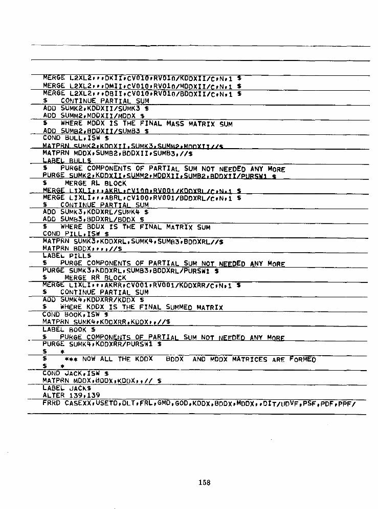
COND JACK,ISW $MATPRN MDDX,BODX,KDDX_t// $LABEL JACKSALTER 139,139
FRRD CASEXX,USETD,DLT,FRL,GMD,GOD,KDDX_BDDX,MDDX,,DIT/UDVF,PSF,PDF,PPF/
158

C,N,DISP/C,N,DIRECT/V_NtLUSETD/V_NwMPCFI/VwN_SINGLE/VwN_OMIT/V,NpNONCUP/V,N,FRQSET/CwY,DECOMOPT=I $
ALTER I_0COND ABE,ISW $
$ PRINT THE FORCE VECTORS USED BY THE EQUIVALENT PERIODIC STRUCTUREMATPRN P_F,PSFtPPF,,// $
$ PROCESS THE LEFT AND RIGHT PERIODIC CUT FORCESADD SAVMD_,SAVKDD/OSAV/V,Y,NOMEG2/V,Y,PONE $
ADD DSAV,SAVBDD/KNET/V,YwPONE/VfY,FIOMFG $PURGE DSAV/PURSWl $
MPYAD KNET,UDV_,/FORVEC/C,Np0/C,N,1/C,NpQ/c,N,1MATPRN KNET,UDVF,FORVECwp// $LABEL ABE $ENDALTER
CEND
C A SF CONTROL DECK _ CHO
TITLE = PERIODIC STRUCTURE (FIRST sAMPLE)MAXLINES = 30nQODLOAD = 10
_ FREQUENCY : 1OLOAD = ALL
DISPLACEMENT = ALLBE_IN _ULK
159

S 0 R T E O R U _ K D A T A ..E C H O
1 ,, 2 .. 3 ,, 4 °. 5 ,, 6 .. 7 .. 8 .- 9 °. 10 •DAMP2 161 .... _,0_293"! "2
CHAMP2 106 8.14587 6 2CDAMP2 197 4.07293 7 2CODMEM I t 2 5 4 3CQDMEM 2 t 1 6 5 2CQDMEM 3 _ 4 5 8 9CQDMEM 4 1 5 6 7 BDAREA 21 3 2 -W9,8972DAREA 21 4 2 -q9,794_DAREA 210 3 2 -_9,9742DLOAD 10 1. 1, 100 1, 101DMI CVOOi 0 2 % 1 _B $DMI CVO01 1 13 t, 1. 1. 1. 1. DOGS+OGS t,DMI CV010 0 2 1 1 18 1DMI CV010 1 7 1, I, 1. 1, 1. pIGS+IGS 1,DMI CVlO0 0 2 t 1 18 1DMI CVlO0 1 1 1, 1, 1, 1, 1, CATS+ATS 1,DMI LIXLI 0 2 1 1 12 12DMI LIXLI 1 1 ,0DMI LIXL2 0 2 1 I 12 12DMI LIXL2 I I .0DMI L2XLI 0 2 1 1 12 12DMI L2XLI i I ,0DMI L2XL2 0 2 I 1 12 12DMI _2X_2 1 1 °0DMI UMATR 0 6 t 2 6 6DMI VMATR 1 _ I,DMI UMATR 2 2 1,OUl UMATR 3 3 _,DMI UMATR _ 4 1.DMI UHATR 5 5 11DMI UMATR 6 6 1,DPHASE 23 3 2 26,63T8DPHASE 23 4 2 38°18377DPHASE 230 3 2 22,273_7FREe 1 3000.GRDSET 3456GRID 1 °0 ,0 o0GRID 2 ,0 1,0 ,06RID 3 ,0 2.0 ,0GRID 4 1,0 2,0 .0GRID 5 1,0 1,0 .gGRID 6 1°0 .0 .oGRID 7 2mO *0 ,0GRID 8 2,0 1,0 ,0GRID 9 _,0 2,0 ,0
• MAT2 10 3_5600, 345_00, .0 3_5600, .000096PARAM CMST ,9029168,0PARAM FIOMEG 1,0-20" 18849.55PARAM NOMEG_ -3,553+8.0PARAM NONE -1,0 ,0PARAM N_MRRn -_.2Rn-_.nPARAM NSMSTO -8108,830°0PARAM PONE +1.0 .0PARAM SMSBO +2,280-5°0PARAM SMSTQ +8108.830,0PeOMEM 1 10 1,0RLOAnl inn _1 _ 22RLOAD1 101 210 230 22TABLED1 2_ PUL_I+ULS1 0,0 1.0 lO.OnO0, 1,0 ENDTENDDAfA
160

APPENDIX B (NASTRAN DEMONSTRATIONPROBLEMOUTPUT):_E_UFLNCY =.....-3_00060--O--+b3-.................................................... =C__O_._.Nt._B._.L_E_X_I 0 a D V. Er T o R
(REAL/IMAGINARY)
• OINT ID, TYPE T1 T2 T3 RI R2 R3
........ ,0 ........... -=_?_8562__+J_L.... _n .... _ __,_E____ ,0___
.... _ G .... ,0 -7,8l_4159+01 ' ._ ,O _0 tO,0 -6,1691_7+01 .p ,0 .0 ,0
"REQUENCY = 3, OOnO0()_-03 ............... ......
C. 0 M P L E X S T R_.E S..S E S ..... ,I...N...... _Q V._A___D_R__I_J=___T_,_A__J=_ .... M F ._ B__R__N E S ( C e D M E.M_)_( N_ALi _;-',_.C: ,L.'.*.°Y)
" EL_EMENT .......................... - STR-_SES--_ ELEMENT COORDIN-ATE-S-Y-S-TE-M--. ......
ID, real o _'_Tn_,__. real o real ox_ _ imag _yyxx .....:,,_rz,,_.__....._Ly imag 0__ "_ _ma.g_Oxyw 1 -9o069812+01/, -9, n69812+01 ,n /, - _ 31_65---2-_+_-01 -W,316528+O1/t ,0c_ 2 -9,808248+01/p -9,8_82_8+01 ,0 /w "2L207309+01 "2__20.7309+01/L_ tO
3 -7", 895863+01/ ," " ---7,895863_+'01 "0 /' "6,209007+01 --6,20-9007+01_, -,0 .......tt -9,080797+01/, .....................-9,080797+01 ,.0_ /_' "u,J 51 q.?-__q') + O_ -t.t, 31Q'__4.__0 _....
TABLE B-1
NASTRAN-EXACTSOLUTION COMPARISON
-e_plement_ NASTRAN EXACT NASTRAN EXACTIPl,psi IPI, psi Phase of p Phase of p
1 100.53 100o00 12.6830 12.728°
2 100.44 100o00 25.451° 25.456°
3 100o44 100.00 38.180° 38.183°
4 100o53 100.00 25.4120 25°456°
F}n {F}n+1 ,
..,o. n n+1 ! n+Z I
Lp _ "°"
a) Total Periodic Structure left Iright
cut llCUt
I
_--_. I 2 .--_F:_b) nth SubstructureSign _
Convention --.w • . : ---_ _-
L .x, ,, _ _u,_
s. 3-(IF_) = P1/2 ooo applied
c) Force Decomposition -- = : Y force at node onAt Cut left cut
,_ I_ ._ (2Fa)y = P2 °'° applied?IZ._ force at node
_[_ offleftcut{IF_})
Fig. 1 Periodic Structure Notation
162

.x
!_ !_ll _
Cylindrica_ -- - ] -__ShelI !
!'C_= poei( kx
._...,, ",_.,.,.:i..,.,o I _.......I ....... (F_- L,--_ I -[............ Ib) InfiniteRibbedPlate _--- i ........
-blL,h--Fig.2)InfinitePeriodicStructures
c) SubmergedLayered
, Foei(O_t) Plate
Foe1(315+ mt) |
Foei(270+_t-L---_ i. !-_--- F ei(90%t)
Foei(135 + _t)
_*-- 450 Foei(180 +_ t)
F,Tg.3 Cyclic Periodic Structure
163

FluidMedia
PlanePressureWave
p:Poi(kr+_t)r=x Cos_+ySin_
a) PlanePressureWaveThroughHomogenousMedium
_(gF a) not an• _ "y explicitly
+Y_ _ appliedforce
:u,,t cut(3 ,y
Typical unknown /'- "_ G/C) /.._ j-,,_, l! _" "_f Typicalunknown |Z I ,_._' rightcut force H
left cut force_'_;: 15 8" • .,'
___41,,t .16 7.1A _
absorbers _ Lp b) FiniteElementModelfor DottedRegionofFig° 4a
Fig.4 DemonstrationProblem
164