std plans noise barrier wall type 14 - washington state … · 2014-02-27 · 1 design memorandum....
TRANSCRIPT
1
Design Memorandum
TO: All Design Section Staff FROM: Bijan Khaleghi DATE: February 19, 2014 SUBJECT: STD Plans Noise Barrier Wall Type 14
This memorandum supersedes the design memorandum issued on January 14, 2012 for Type 14 Precast Concrete Noise Barrier Wall on Shaft Foundation. The January 14, 2012 policy memorandum remains effective for all other types of noise barrier walls until further notice.
The design of the Standard Plan Noise Barrier Type 14 is in accordance with the requirements of the AASHTO LRFD Bridge Design Specifications, 6th Edition 2012 and interims through 2013, and the requirements and guidance cited herein:
1. Load factors and load combinations for the design of all structural elements is in accordance with AASHTO LRFD Tables 3.4.1-1 and 3.4.1-2.
2. Seismic design is in accordance with AASHTO LRFD Article 3.10.2.1-General Procedure, considering site classes B, C, D, and E and the following: a. Peak seismic ground acceleration coefficient on Rock (Site Class B).
• PGA = 0.45g for Western Washington • PGA = 0.19g for Eastern Washington
b. Horizontal response spectral acceleration coefficient at 0.2-sec period on rock (Site Class B). • Ss = 1.00 for Western Washington • Ss = 0.43 for Eastern Washington
c. Horizontal response spectral acceleration coefficient at 1.0-sec period on rock (Site Class B). • S1 = 0.33 for Western Washington • S1 = 0.15 for Eastern Washington
d. Modal analysis was performed for the first four periods. The elastic seismic response coefficient Csm was computed for each modal period in accordance with AASHTO LRFD Article 3.10.4.2 and all four Csm coefficients were combined through the SRSS method.
e. The resultant seismic force is considered to act at a height of 0.71H above the top of the shaft, where H is the total height measured from the top of the panel to the top of the shaft.
3. Wind loads are computed in accordance with AASHTO LRFD Article 15.8.2 considering surface
conditions characterized as “Sparse Suburban”. The 50 year return period maximum wind velocity, as determined from AASHTO LRFD Figure 15.8.2-1, is 100 mph for Western Washington and 80 mph for Eastern Washington.

2
4. Barrier is designed for minimum Test Level 4 (TL-4) vehicular collision loads in accordance to AASHTO LRFD Article 13, and shafts are designed for an equivalent static load of 10 kips.
5. Drilled shaft foundations are designed for earth pressure distributions as shown in AASHTO LRFD Figure 3.11.5.10-1 considering the following: a. Shaft depth, D1
• 2H:1V fore-slope and a flat backslope • Angle of internal friction = 32 degrees • Soil unit weight = 125pcf • Corresponding Kp = 1.5 • Corresponding Ka = 0.28
b. Shaft depth, D2 • 2H:1V fore-slope and a flat backslope • Angle of internal friction = 38 degrees • Soil unit weight = 125pcf • Corresponding Kp = 2.3 • Corresponding Ka = 0.22
c. The passive earth pressure distribution is assumed to start at the finished grade. However, the uppermost two feet of passive earth pressure is neglected, resulting in a trapezoidal passive earth pressure distribution.
d. In accordance with AASHTO LRFD Table 11.5.7-1 and Article 11.5.8, the resistance factor applied to the passive earth pressure is as follows: • For the Strength Limit State, the resistance factor is taken as 0.75. • For the Extreme Event Limit State, the resistance factor is taken as 1.0.
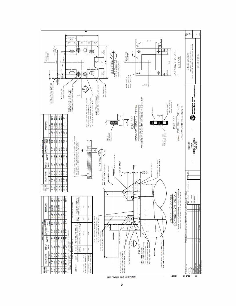
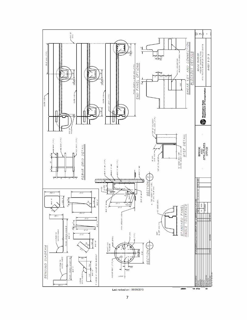
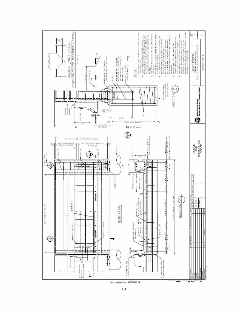
The details for the Type 14 Noise Barrier Wall is attached for immediate use.
Barrier could be either precast or cast-in-place and barrier shape could be Type F (shown), single slope or others TL-3 and TL-4 barrier systems.
Background:
WSDOT is in process of upgrading STD Plans Manual M21-01 Noise Barrier Walls to the current AASHTO LRFD Bridge Design Specifications, WSDOT Bridge Design and Geotechnical Manuals. This memorandum addresses the design of Type 14 STD Plans Noise Barrier Walls to the current requirement.
For TL-3 and TL-4 barrier systems, the equivalent static load (ESL) is 10 kips per NCHRP 663 and shall be applied to each shaft.

3
If you have any questions regarding this memorandum, please contact David Sawahata at 360-705-6941 ([email protected]), Monique Pawelka at 360-705-7754 ([email protected]), or Bijan Khaleghi at 360-705-7181 ([email protected]) .
cc: Mark Gaines, Bridge Construction - 47354
Craig Boone, Bridge and Structures – 47340

4

5
6
7

8
BDM Revisions: 8.1.3 Design
F. Noise Barrier Walls
The design of the Standard Plan Noise Barrier Type 14 is in accordance with the requirements of the AASHTO LRFD Bridge Design Specifications, 6th Edition 2012 and interims through 2013, and the requirements and guidance cited herein:
6. Load factors and load combinations for the design of all structural elements is in accordance with AASHTO LRFD Tables 3.4.1-1 and 3.4.1-2.
7. Seismic design is in accordance with AASHTO LRFD Article 3.10.2.1-General Procedure,
considering site classes B, C, D, and E and the following: a. Peak seismic ground acceleration coefficient on Rock (Site Class B).
• PGA = 0.45g for Western Washington • PGA = 0.19g for Eastern Washington
b. Horizontal response spectral acceleration coefficient at 0.2-sec period on rock (Site Class B). • Ss = 1.00 for Western Washington • Ss = 0.43 for Eastern Washington
c. Horizontal response spectral acceleration coefficient at 1.0-sec period on rock (Site Class B). • S1 = 0.33 for Western Washington • S1 = 0.15 for Eastern Washington
d. Modal analysis was performed for the first four periods. The elastic seismic response coefficient Csm was computed for each modal period in accordance with AASHTO LRFD Article 3.10.4.2 and all four Csm coefficients were combined through the SRSS method.
e. The resultant seismic force is considered to act at a height of 0.71H above the top of the shaft, where H is the total height measured from the top of the panel to the top of the shaft.
8. Wind loads are computed in accordance with AASHTO LRFD Article 15.8.2 considering surface
conditions characterized as “Sparse Suburban”. The 50 year return period maximum wind velocity, as determined from AASHTO LRFD Figure 15.8.2-1, is 100 mph for Western Washington and 80 mph for Eastern Washington.
9. Barrier is designed for minimum Test Level 4 (TL-4) vehicular collision loads in accordance to AASHTO LRFD Article 13, and shafts are designed for an equivalent static load of 10 kips.
10. Drilled shaft foundations are designed for earth pressure distributions as shown in AASHTO LRFD Figure 3.11.5.10-1 considering the following: a. Shaft depth, D1
• 2H:1V fore-slope and a flat backslope • Angle of internal friction = 32 degrees
9
• Soil unit weight = 125pcf • Corresponding Kp = 1.5 • Corresponding Ka = 0.28
b. Shaft depth, D2 • 2H:1V fore-slope and a flat backslope • Angle of internal friction = 38 degrees • Soil unit weight = 125pcf • Corresponding Kp = 2.3 • Corresponding Ka = 0.22
c. The passive earth pressure distribution is assumed to start at the finished grade. However, the uppermost two feet of passive earth pressure is neglected, resulting in a trapezoidal passive earth pressure distribution.
d. In accordance with AASHTO LRFD Table 11.5.7-1 and Article 11.5.8, the resistance factor applied to the passive earth pressure is as follows: • For the Strength Limit State, the resistance factor is taken as 0.75. • For the Extreme Event Limit State, the resistance factor is taken as 1.0.
The details for the Type 14 Noise Barrier Wall is attached for immediate use.
Barrier could be either precast or cast-in-place and barrier shape could be Type F (shown), single slope or others TL-3 and TL-4 barrier systems.
10

11

12