· pdf filethe design of the stauff accumulator makes use of the difference in the...
TRANSCRIPT
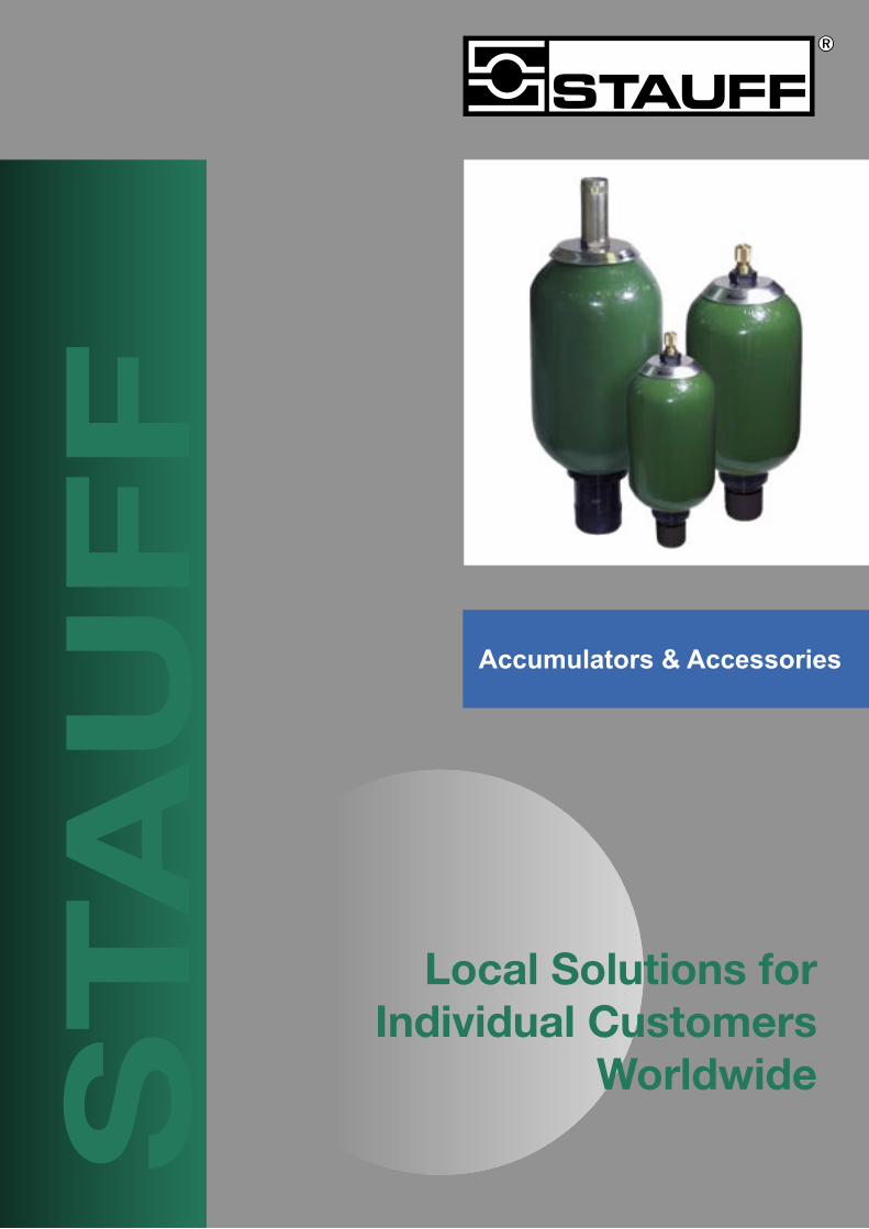
Local Solutions forIndividual Customers
WorldwideSTA
UF
F
Accumulators & Accessories
2
Accumulators & Accessories Page
Introduction 3
Material Options & Features 4, 5
Bladder Accumulators - STBA
Dimensions 6
Ordering Codes 7
Diaphragm Accumulators - STDA
Dimensions 8
Ordering Codes 9
Safety Blocks - STASB
General Information and Ordering Code 10
Bladders - STB
Dimensions 11
Ordering Codes 7
Anti-Extrusion Rings (AER) 11
Accessories
Accumulator Adaptors 10
Clamps and Brackets 12
Charging Kit - STA-CK-1 13
Services and Sizing
Precharging Procedure 14
Maintenance 15
Installation 16
Disassembly and Reassembly Instructions 17,18
Accumulators Sizing Chart for Storage Applications 19
Contents
3
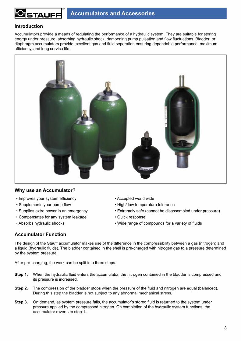
IntroductionAccumulators provide a means of regulating the performance of a hydraulic system. They are suitable for storing energy under pressure, absorbing hydraulic shock, dampening pump pulsation and fl ow fl uctuations. Bladder or diaphragm accumulators provide excellent gas and fl uid separation ensuring dependable performance, maximum effi ciency, and long service life.
Why use an Accumulator?• Improves your system effi ciency • Accepted world wide• Supplements your pump fl ow • High/ low temperature tolerance• Supplies extra power in an emergency • Extremely safe (cannot be disassembled under pressure)• Compensates for any system leakage • Quick response• Absorbs hydraulic shocks • Wide range of compounds for a variety of fl uids
Accumulator Function
The design of the Stauff accumulator makes use of the difference in the compressibility between a gas (nitrogen) and a liquid (hydraulic fl uids). The bladder contained in the shell is pre-charged with nitrogen gas to a pressure determined by the system pressure.
After pre-charging, the work can be split into three steps.
Step 1. When the hydraulic fl uid enters the accumulator, the nitrogen contained in the bladder is compressed and its pressure is increased.
Step 2. The compression of the bladder stops when the pressure of the fl uid and nitrogen are equal (balanced).During this step the bladder is not subject to any abnormal mechanical stress.
Step 3. On demand, as system pressure falls, the accumulator’s stored fl uid is returned to the system under pressure applied by the compressed nitrogen. On completion of the hydraulic system functions, the accumulator reverts to step 1.
Accumulators and Accessories

4
Material Options and Features
MainComponents
StandardMaterial
MaterialOptions Features
Shell
• Alloyed Steel
• All Sizes Comply with AS1210 Materials Specifications
• Bare Metal
• Epoxy paint external
Consult Stauff
• Seamless shell construction• Documentation to AS4343
provided• Available with Foreign
or Domestic Certificates (Consult Stauff)
Bladder • Low temperature Buna-N (NBR)
Viton - (V)EPR - (E)
Hi-Temp Buna (HBR)
Consult Stauff forother options
• 1 piece fully enclosed moulded bladder
• With moulded steel valve stems
• Wide range of operatingtemperatures
Oil PortAssembly • AISI 4130 material spec. Consult Stauff
• Proven design and reliability• Port options available, refer
to ordering code
Bladder Accumulator Maximum Flow Rates• Test Pressure (bar): 1.25 x Design Pressure• Min/Max Working Temperature acceptable (°C): -20 / ±80• Min/Max Storage temperature (°C): -40 / ±80• Meets AS1210 and AS4343 specifications• Meets 4 –1 design factor at normal operating pressures.• Available with foreign certificates (upon request)• Generally available from stock.
Size (litres)Max. Recommended Flow
LPM1 & 2.5 336
4 56410 - 57 1176
Accumulators and Accessories

5
1 ShellBladder accumulator shells are made from chrome-molybdenum alloy steel (SA372) with forged ends for maximum strength. All sizes comply with AS1210 material specifications, and documentation to AS4343 are provided.
2 BladderStauff bladders are manufactured from the most advanced elastomers which are capable of meeting a wide range of systems requirements. Bladders are offered in a variety of compounds to meet a, wide range of fluids and operating temperatures. Standard material is low temperature Buna –N (NBR).
3 Bladder StemAll bladder accumulators, sizes 4 litre and larger, are fitted as standard with two-piece bladder stems with replaceable gas valve cartridge for ease of serviceability.
4 Port AssembliesStandard oil service ports are made from high-strength alloy steel for maximum durability.
5 Fluid PortBSPP(standard), NPT and Split Flange Adapters are available (See page 10). Bleeder ports (plugged) are included as standard on sizes 4 litre and larger.
6 Gas ValveAll accumulators are fitted with a gas valve for ease of gas pre-charging. 4 litre and larger units are equipped with a cored gas valve cartridge (ISO-4570-8V1) for ease of maintenance. For safety, the gas valve will vent if unscrewed.
Material Options and Features
1
2
3
4
6
5
Accumulators and Accessories

6
Stauff Bladder Accumulator Dimensions and Specifications(Conforming to AS 1210)
Nominal Capacity (Litres)
Max.W.P.(bar)
Dimensions Net Weight
A B C ød øD øF G øH SW on flatsKg
mm mm mm mm mm BSPF Bleed Plug mm mm1.1 400 321 54 80 22.5 117 G3/4” N/A 101 32 5.72.5 400 522 54 80 22.5 118 G3/4” N/A 101 32 104 345 446 65 80 22.5 168 G1 1/4” Hex 19 a/f 101 70 14
10 210 585 103 80 22.5 222 G2” Hex 19 a/f 101 70 2720 210 891 103 80 22.5 222 G2” Hex 19 a/f 101 70 4225 210 1041 103 80 22.5 222 G2” Hex 19 a/f 101 70 5537 210 1428 103 80 22.5 222 G2” Hex 19 a/f 101 70 6650 210 1933 103 80 51 222 G2” Hex 19 a/f 101 70 9257 345 2003 103 80 22.5 229 G2” Hex 19 a/f 101 70 125
ø D
BSWG
ø F
J
A
ø d
C
Kø I
/flats
ø HO' r ing
For Support Brackets and Clamps refer to page 12.
Advantages• Medium Pressure: 4-57 Lt• High Pressure: 1.1-2.5 Lt• Small diameter• Improved corrosion protection for fluid port and protection cap• Stronger gas valve• Standard 1176 L/Min High flow fluid port
Accumulators and Accessories
7
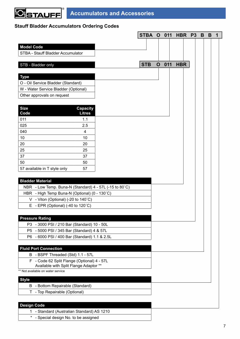
Stauff Bladder Accumulators Ordering Codes
Model CodeSTBA - Stauff Bladder Accumulator
TypeO - Oil Service Bladder (Standard)W - Water Service Bladder (Optional)Other approvals on request
STB - Bladder only
SizeCode
CapacityLitres
011 1.1025 2.5040 410 1020 2025 2537 3750 5057 available in T style only 57
Bladder MaterialNBR - Low Temp. Buna-N (Standard) 4 - 57L (-15 to 80˚C)HBR - High Temp Buna-N (Optional) (0 - 130˚C)
V - Viton (Optional) (-20 to 140˚C)E - EPR (Optional) (-40 to 120˚C)
Pressure RatingP3 - 3000 PSI / 210 Bar (Standard) 10 - 50LP5 - 5000 PSI / 345 Bar (Standard) 4 & 57LP6 - 6000 PSI / 400 Bar (Standard) 1.1 & 2.5L
Fluid Port ConnectionB - BSPF Threaded (Std) 1.1 - 57LF - Code 62 Split Flange (Optional) 4 - 57L
Available with Split Flange Adaptor **** Not available on water service
StyleB - Bottom Repairable (Standard)T - Top Repairable (Optional)
Design Code1 - Standard (Australian Standard) AS 1210* - Special design No. to be assigned
STBA O 011 HBR P3 B B 1
STB O 011 HBR
Accumulators and Accessories
8
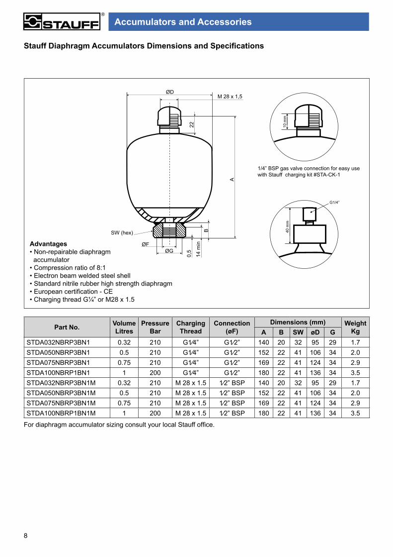
Part No. VolumeLitres
PressureBar
Charging Thread
Connection(øF)
Dimensions (mm) WeightKgA B SW øD G
STDA032NBRP3BN1 0.32 210 G1⁄4” G1⁄2” 140 20 32 95 29 1.7STDA050NBRP3BN1 0.5 210 G1⁄4” G1⁄2” 152 22 41 106 34 2.0STDA075NBRP3BN1 0.75 210 G1⁄4” G1⁄2” 169 22 41 124 34 2.9STDA100NBRP1BN1 1 200 G1⁄4” G1⁄2” 180 22 41 136 34 3.5STDA032NBRP3BN1M 0.32 210 M 28 x 1.5 1⁄2” BSP 140 20 32 95 29 1.7STDA050NBRP3BN1M 0.5 210 M 28 x 1.5 1⁄2” BSP 152 22 41 106 34 2.0STDA075NBRP3BN1M 0.75 210 M 28 x 1.5 1⁄2” BSP 169 22 41 124 34 2.9STDA100NBRP1BN1M 1 200 M 28 x 1.5 1⁄2” BSP 180 22 41 136 34 3.5
Stauff Diaphragm Accumulators Dimensions and Specifications
1/4” BSP gas valve connection for easy use with Stauff charging kit #STA-CK-1
For diaphragm accumulator sizing consult your local Stauff office.
Advantages• Non-repairable diaphragm accumulator• Compression ratio of 8:1• Electron beam welded steel shell• Standard nitrile rubber high strength diaphragm• European certification - CE• Charging thread G¼” or M28 x 1.5
10 m
m
Accumulators and Accessories
40 m
m
G1/4”
ØDM 28 x 1,5
22
A
B14
min
0,5
SW (hex)
ØGØF

9
STDA 032 NBR P3 B N 1 M
Stauff Diaphragm Accumulators Ordering Code
Model CodeSTDA - Stauff Diaphragm Accumulator
SizeCode
CapacityLitres
032 0.32050 0.5075 0.75100 1
Pressure RatingP1 - 2900 PSI/200 Bar (Standard) 1LP3 - 3000 PSI/210 Bar(Standard) 0.32,0.5,0.75L
Fluid Port ConnectionB - G1/2 BSPF (Standard)
StyleN - Non Repairable (Standard)
Design Code1 - Standard (Certified European - CE)* - Special design No. to be assigned
Diaphragm MaterialNBR - Low temp Buna - N (Standard) -15 to 80˚C
Charging Thread- G¼
M - M 28 x 1.5
Accumulators and Accessories
10
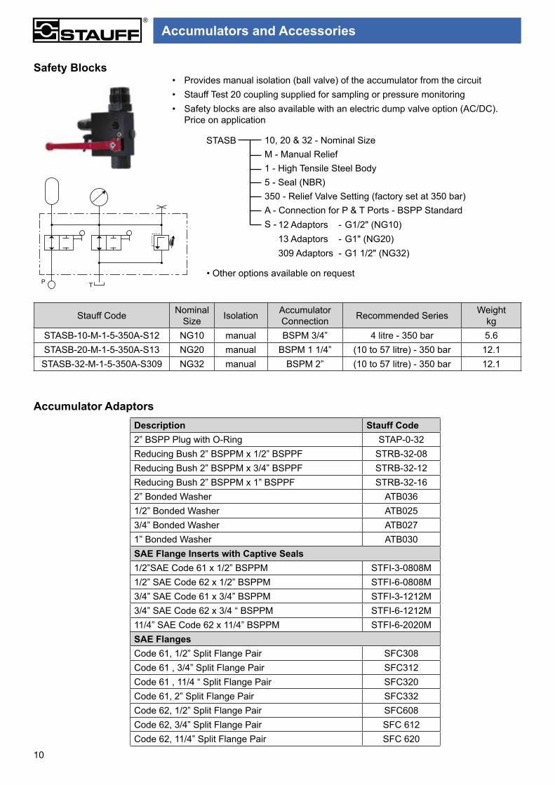
• Provides manual isolation (ball valve) of the accumulator from the circuit• Stauff Test 20 coupling supplied for sampling or pressure monitoring• Safety blocks are also available with an electric dump valve option (AC/DC).
Price on application
Safety Blocks
Stauff Code Nominal Size Isolation Accumulator
Connection Recommended Series Weightkg
STASB-10-M-1-5-350A-S12 NG10 manual BSPM 3/4” 4 litre - 350 bar 5.6STASB-20-M-1-5-350A-S13 NG20 manual BSPM 1 1/4” (10 to 57 litre) - 350 bar 12.1
STASB-32-M-1-5-350A-S309 NG32 manual BSPM 2” (10 to 57 litre) - 350 bar 12.1
Accumulator AdaptorsDescription Stauff Code2” BSPP Plug with O-Ring STAP-0-32Reducing Bush 2” BSPPM x 1/2” BSPPF STRB-32-08Reducing Bush 2” BSPPM x 3/4” BSPPF STRB-32-12Reducing Bush 2” BSPPM x 1” BSPPF STRB-32-162” Bonded Washer ATB0361/2” Bonded Washer ATB0253/4” Bonded Washer ATB0271” Bonded Washer ATB030SAE Flange Inserts with Captive Seals1/2”SAE Code 61 x 1/2” BSPPM STFI-3-0808M1/2” SAE Code 62 x 1/2” BSPPM STFI-6-0808M3/4” SAE Code 61 x 3/4” BSPPM STFI-3-1212M3/4” SAE Code 62 x 3/4 “ BSPPM STFI-6-1212M11/4” SAE Code 62 x 11/4” BSPPM STFI-6-2020MSAE FlangesCode 61, 1/2” Split Flange Pair SFC308Code 61 , 3/4” Split Flange Pair SFC312Code 61 , 11/4 “ Split Flange Pair SFC320Code 61, 2” Split Flange Pair SFC332Code 62, 1/2” Split Flange Pair SFC608Code 62, 3/4” Split Flange Pair SFC 612Code 62, 11/4” Split Flange Pair SFC 620
TP• Other options available on request
10, 20 & 32 - Nominal SizeM - Manual Relief1 - High Tensile Steel Body5 - Seal (NBR)350 - Relief Valve Setting (factory set at 350 bar)A - Connection for P & T Ports - BSPP StandardS -
STASB
12 Adaptors - G1/2" (NG10)13 Adaptors - G1" (NG20)309 Adaptors - G1 1/2" (NG32)
Accumulators and Accessories

11
Stauff offer a wide range of bladder materials to suit most applications. Please consult Stauff for details of bladder compatibility, with fl uid and fl uid temperature.
Table 1 gives the range of bladder materials available with their corresponding working temperature when handling non-aggressive fl uids.
Table 2 can be used to distinguish bladder capacities by overall dimensions. For other bladder materials consult Stauff.
Stauff Code Bladder MaterialTemperature Rangefrom ˚C to ˚C
NBR Low Temperature Buna-N(Standard) -15 80HBR High Temperature Buna-N 0 130
V Fluorocarbon(Viton) -20 140E Ethylene Propylene (EPR) -40 120
AccumulatorCapacity (l)
Nominal
DimensionH mm
DimensionD mm
0.16 154 410.6 132 731.1 147 912.5 335 1004.0 203 142
10.0 283 19820.0 610 19837.0 1128 19850.0 1603 19857.0 1703 198
Table 1
Table 2Bladder Kit
Bladder Dimension Tables
H
D
Anti Extrusion Ring Assembly
Stauff Part No. Accumulator Size Connection to Accumulator BSPMSTB-AER-01 1.1, 2.5L G3/4”STB-AER-02 4L G1 1/4”STB-AER-03 10 - 57L G2”
• Anti extrusion ring (AER) assembly includes the moulded anti extru-sion ring with split ring, fl uid port (or top plug) O-ring and back-up ring & bleed plug bonded seal for 4 to 57 litre.
• Oil service AER supplied in nitrile carbon steel split ring (standard). For water service, AER incorporates a stainless steel split ring.
InterchangeabilityStauff bladders are fully interchangeable with common European brands.
Always quote full Part No. e.g.STB-O-011-NBR, capacity, Nitrile Rubber, 1/4” BSP.
The kit comprises of :- Bladder - Back up ring- Gas valve - Protective Cap*- Lock nut - Bleed plug seal*- Fluid port ‘O’-Ring
*4L capacity and above onlyAnti-extrusion ring assembly supplied separately, refer below.
Fluid port assemblies are available on request.
Description Stauff CodeBladder Assembly to suit 1.1L Accum. STB-0-011-NBR
Bladder Assembly to suit 2.5L Accum. STB-0-025-NBR
Bladder Assembly to suit 4L Accum. STB-0-040-NBR
Bladder Assembly to suit 10L Accum. STB-0-010-NBR
Bladder Assembly to suit 20L Accum. STB-0-020-NBR
Bladder Assembly to suit 37L Accum. STB-0-037-NBR
Bladder Assembly to suit 50L Accum. STB-0-050-NBR
Bladder Assembly to suit 54L Accum. STB-0-054-NBR
Bladder Kit - Ordering Codes
Accumulators and Accessories
12
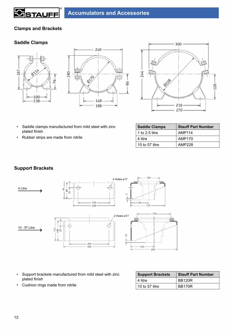
Clamps and Brackets
Support Brackets
• Saddle clamps manufactured from mild steel with zinc plated finish
• Rubber strips are made from nitrile
• Support brackets manufactured from mild steel with zinc plated finish
• Cushion rings made from nitrile
Saddle Clamps Stauff Part Number1 to 2.5 litre AMP1144 litre AMP17010 to 57 litre AMP228
Support Brackets Stauff Part Number4 litre BB120R10 to 57 litre BB170R
4 Litre
10 - 57 Litre
Saddle Clamps
4 Holes ø17
2 Holes ø17
Accumulators and Accessories

13
- Stauff recommend the use of nitrogen gas only for pre-charging of accumulators.- Always wear protective safety glasses.
- Pressure gauge is a safety pattern type to AS1349-1986
The kit has adaptors to connect the hose to the nitrogen cylinder as well as adaptors to connect the control valve to the accumulator.
- Optional: 0-17000 kPa outlet nitrogen regulator. Code SAR017000
Charging Kit #STA-CK-1
SAA 10143SAA 50019
SAA 2069TSAAGAS531
SAA 50510
SAA 2069
Note: Pictures not to scale.
Order Code Description1 STA -CK -1 Accumulator Charge Kit
Comprising of:2 SAA50019 0.302 x 32 TPI adaptor3 SAA10143 7.8” UNF adaptor4 SAA50510 ¼” ISO 228 adaptor5 SAAGAS531 Type 50 - ¼” BSPT bottle adaptor6 SAA2069 Valve7 SAA2069T Valve tool
8 SAAPC2156/250 Charging/pre - loading/gauge set, 0-250 BAR
9 SMS20/B ¼-2000BGAS Hose assembly - 2m
To maintain optimum performance in hydraulic systems employing accumulators, it is recommended that the gaspre-charge pressure be checked regularly. A loss in the gas pre-charge pressure will cause a drop in the system effi ciency and may cause damage to the accumulator bladder, diaphragm or piston.
The charging kit allows hydro-pneumatic accumulators, whether bladder type, diaphragm type or piston type, to be charged with nitrogen to the desired pressure. For this purpose, the kit is connected to a commercially available nitrogen cylinder by a fl exible hose.
The kit can also be used by technicians to check the current gas pre-charge pressure. The control valve incorporates a pressure gauge to permit direct pressure readings as well as a check valve to prevent back fl ow in the case of low pressures in the nitrogen cylinder. A manual bleed valve allows excess pressure to be reduced to the desired operating pre-charge level.
Please contact your local Stauff office for other adaptors.
1
2
5
3
6
4
7
9 8
Accumulators and Accessories

14
• Prior to commissioning a hydraulic system, any accumulators in the system should have their pre-charge pressure checked and adjusted.
• The condition of the accumulator is primarily determined by periodic checking of the pre-charge pressure.• Hydraulic Accumulators are pressure vessels and only qualified personnel should perform maintenance.• Drain all fluid completely from accumulator before performing any maintenance.• DO NOT weld or braze directly on accumulator shell.• DO NOT use automotive type valve cores as high pressure accumulator gas valves.• The most accurate pre-charge readings can only be taken when fluid pressure is at zero.• Always observe the maximum working pressure and operating temperature ranges.
Precharging ProcedureGeneral Information
Pre-charging Bladder Accumulators
A Isolate the accumulator from the system, open the drain valve and make sure hydraulic fluid pressure is zero.B Remove gas valve protection cap and valve cap from the accumulator.C To charge the accumulator, use a charging hose and gauge assembly from the Stauff Charging Kit # STA-CK-1
rated for 250 bar maximum.D Before using the charging assembly (Figure 1.) make sure that valve A is completely open (counter-clockwise),
and that bleed valve B (Figure 1.) is closed.E Connect the charging unit to the gas fill valve on the accumulator by means of knurled cap D (Figure 1.).F Fit the gas bottle adaptor (included in Stauff charging kit) to the nitrogen bottle, make sure that the gas valve on
the nitrogen bottle is closed (see Figure 2.) then attach gas hose to the gas bottle adaptor on the nitrogen bottle.G Connect the other end of gas hose to the Stauff test coupling C (Figure 1.), after taking off its cap.H Turn valve A (Figure 1.) clockwise to the point where resistance is felt or pressure is registered on the
gauge(only if there is an existing pre-charge).I SLOWLY open valve on nitrogen bottle (Figure 2.) and allow the gas to flow to the accumulator.J When the pressure in the accumulator is slightly higher than is required, close the valve on the nitrogen bottle.K Open valve A (Figure 1.) (counter-clockwise) and reduce the pressure in the gas hose and charging assembly to
zero by means of bleed valve B (Figure 1.).L Remove hose from non-return Stauff test coupling C (Figure 1.) and replace cap.M Close the bleed valve B (Figure 1.) and wait a few minutes for pressure to stabilise.N Screw valve A (Figure 1.) clockwise until pressure can be read on gauge. This should be slightly higher than the
required pressure.O Adjust pressure by means of bleed valve B (Figure 1.), then unscrew valve A (Figure 1.), counterclockwise.
Open valve B (figure 1) then remove charging unit.P Replace gas valve cap and protective cap on accumulator. Accumulator is now ready for use.
NOTE: Allow accumulator to rest about 10-15 minutes after gas pre-charging. This will allow gas temperature to adjust and equalise. Recheck gas pre-charge pressure and adjust if necessary. Check accumulator gas valve for any leaks with soapy water. Always wear safety glasses.
Figure 1 Figure 2
A
B
C
D
- Safety pattern gauge.
Accumulators and Accessories

15
MaintenanceGeneral InformationThe condition of the accumulator is primarily determined by periodic checking of gas pre-charge pressure. Only qualified personnel should perform any maintenance on accumulators. Nitrogen gas pre-charge pressure should be checked at least once during the first week of operation to ensure that no leak has developed. The pre-charge pressure and ambient temperature should be recorded at installation and checking done at the same temperature if possible. If there is no loss of gas pre-charge pressure, it should be rechecked in approximately 4 months. Thereafter, it should be checked annually. Check pre-charge if the system is acting sluggishly. If pre-charge is low, check gas valve for leakage and recharge.
Bladder Accumulators
1 Use appropriate valving in the hydraulic system to discharge all hydraulic fluid from accumulator.2 To check or adjust pre-charge pressure, HYDRAULIC PRESSURE MUST BE REDUCED TO ZERO.
Pre-charge pressure should be checked periodically.3 Charging and checking should be done with an accumulator charge kit similar to Stauff Part # STA-CK-1.4 Remove gas valve protection cap and valve cap as per pre-charge procedure instructions (B) on page 145 Attach gauge assembly to accumulator gas valve.6 Make sure bleed valve B (Figure 1.) is closed, depress gas valve core gently by turning valve A (Figure 1.)
clockwise. Gas pressure can now be read on gauge.7 To reduce pressure, open bleed valve B (Figure 1.) carefully, allowing gas to escape until desired pressure is
obtained. It the pre-charging pressure is less than required, refer to the pre-charging procedure on page 14
NOTE: Allow accumulator to rest about 10-15 minutes after gas pre-charging. This will allow gas temperature to adjust and equalise. Recheck gas pressure and adjust if necessary. Check accumulator gas valve for any leaks with soapy water.
Figure 1
The kit has adaptors to connect the hose to the nitrogen cylinder as well as adaptors to connect the charging/pre-loading/gauge set to the accumulator.
A
B
C
D
- Safety pattern gauge. According to AS 1349-1986.
- Stauff recommend the use of nitrogen gas only for pre-charging of accumulators.- Always wear protective safety glasses.
Accumulators and Accessories

16
Installation
Item Spare Parts1 Bladder Kit2* Bladder assembly3* Gas valve assembly4 Gas valve cap5 Fluid port assembly6 Anti extrusion ring7* Drain plug with seal (1)8* Seal kit
(1) For accumulators 10 to 57 Litre* These parts are supplied as a kit with instructions.
How to order the Bladder Kit
When placing your order, please indicatethe accumulator part number.
Example: Bladder kit to suit: STBA O 011 HBR P3 B B 1
Prior to any installation, it is necessary to visually check the accumulator in order to detect any possible damage incurred during transport. For optimal operation, the accumulator needs to be located as close as possible to the “application”. It may be installed vertically (gas valve facing up), or horizontallly.
• Avoid standing in the alignment of the connections.• Consider the environmental conditions and if needed, protect the accumulator against heat sources, electrical and magnetic fields, lightning strikes, humidity and foul weather• Keep 200mm over the top of the gas valve free of encumbrance to allow the use of a charging head• Allow free access to the oil drain• Keep all markings visible• Install in such a way so as to prevent any undue stress on the pipework, either directly or indirectly• Clamp the accumulator tightly to a fixed support or alternatively guard it to limit its displacement in case of a connection failure to the hydraulic system• Connect the accumulator to the hydraulic system using the right connectors or flanges• Check the compatibility of the fluid with the materials used• Ensure that the maximum design pressure of the accumulator exceeds the maximum system pressure• Ensure that pressure and temperature limits are not exceeded• Equip the hydraulic system with a pressure relief device• If necessary, add-on a burst disk to account for risks of over pressure associated with thermodynamic effects• Install an appropriate Stauff filtration unit and/or organise regular internal inspections as often as is necessary when dealing with abrasive fluids
It is strictly forbidden to:
• Weld, screw or rivet anything onto the accumulator body• Operate in any way that may alter the mechanical properties of the accumulator• Use the accumulator for construction purposes. (No stress or loading)• Modify the accumulator without prior approval from the manufacturer• Use any other gas than nitrogen for precharging
CommissioningRefer to commissioning instructions supplied with theaccumulator.
For end user requirements regarding regulation inspection and registration, please consult your local Stauff office for details.
Accumulators and Accessories
Accumulators are consideredas pressure vessels.
17
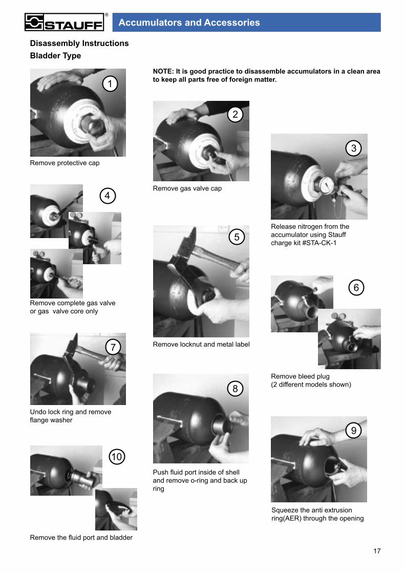
Disassembly InstructionsBladder Type
NOTE: It is good practice to disassemble accumulators in a clean area to keep all parts free of foreign matter.
Remove protective cap
Remove gas valve cap
Release nitrogen from the accumulator using Stauff charge kit #STA-CK-1
Remove complete gas valve or gas valve core only
Remove locknut and metal label
Remove bleed plug(2 different models shown)
Undo lock ring and remove flange washer
Squeeze the anti extrusion ring(AER) through the opening
Push fluid port inside of shell and remove o-ring and back up ring
Remove the fluid port and bladder
1
2
3
4
5
6
7
8
9
10
Accumulators and Accessories

18
Neatly fold the bladder (logitudinally) and squeeze it inside the shell through the fluid end. Locate the gas valve and push it through the opening at the gas end
Remove the gas valve. Squeeze the bladder to discharge air from it. Lubricate the inside of the shell by turning it around on its axis. Use the process fluid or similar liquid
Pace the fluid port inside the shell (poppet first). Fold and place it inside the shell so that metal components are located on the shell opening
Pull the fluid port through the AER. Assemble o-ring, backup ring, flange washer and locking ring (in that order)
Ensure that the fluid port is centred
Tighten the locking ring
Tighten the bleed plug
Mount the metal plate. Tighten the locking nut (on the gas side) and fit the gas valve or gas valve core
Reassembly InstructionsBladder Type
NOTE: It is good practice to assemble accumulators in a clean area to keep all parts free of foreign matter.1
2
3
4
5
6
7
8
The steps outlined in the procedures above show the suggested sequence of events to carry out maintenance on accumulators utilising widely accepted general engineering fitting practices and are not meant to be of a technical nature.These procedures may vary according to accumulator types
NOTE:
Accumulators and Accessories

19
Above volumes in litres discharged between P3/P2
Sizing Chart for Storage Applications
Pressure Ratio
P3/P1≤5
BLADDER ACCUMULATORS
STANDARD BLADDER ACCUMULATORS TRANSFER BARRIER WITH 50L GAS BACK-UP BOTTLE (BUB) FITTED
P3/P2 OB OF 11 O3 O4 10 20 28 37 50/54 57 28+ 1 BUB
37+ 1 BUB
37+ 2 BUB
54+ 1 BUB
54+ 1 BUB P3/P2
1.05 0.005 0.018 0.035 0.08 0.12 0.29 0.57 0.78 1.07 1.49 1.6 2.2 2.46 3.87 2.87 4.28 1.05
1.10 0.01 0.035 0.066 0.14 0.22 0.34 1.09 1.49 2.03 2.84 3.03 4.18 4.69 7.37 5.49 8.16 1.1
1.15 0.015 0.049 0.094 0.21 0.31 0.78 1.55 2.12 2.9 4.04 4.31 5.96 6.73 10.56 7.88 11.73 1.15
1.20 0.019 0.063 0.12 0.26 0.39 0.98 1.97 2.69 3.68 5.13 5.48 7.58 8.6 10.06 14.97 1.2
1.25 0.022 0.074 0.143 0.31 0.47 1.17 2.35 3.2 4.39 6.12 6.53 9.06 10.2 11.94 17.76 1.25
1.30 0.026 0.086 0.149 0.36 0.54 1.35 2.69 3.68 5.03 7.02 7.49 11.91 13.94 1.3
1.35 0.029 0.096 0.183 0.4 0.6 1.5 3.01 4.11 5.62 7.84 8.37 13.11 15.35 1.35
1.40 0.032 0.104 0.201 0.44 0.66 1.65 3.29 4.51 6.16 8.6 9.17 16.77 1.4
1.45 0.034 0.113 0.217 0.47 0.71 1.78 3.56 4.87 6.65 9.28 9.9 18.09
1.50 0.036 0.121 0.231 0.5 0.76 1.9 3.8 5.2 7.11 9.98 10.58 19.33
1.55 0.038 0.128 0.245 0.53 0.81 2.01 4.03 5.51 7.53 10.5 11.2 Above volumes in litres discharged between P3/P2
HOW TO USE CHART ABOVE
1. Use above chart in same way as left but limiting volume discharged to that shown, so that V1-V3 does not exceed 0.80 of actual accumulator shell volume.The corresponding pressure ratio is seen under P3/P2 column.
HOW TO USE THE CHART LEFT
Problem: What Size of Accumulator will discharge 1.4L of liquid between 140bar and 120bar.
1. P3/P2 = 1.17
2. Find the value of P3/P2 which is equal to or next lowest to 1.17. In this case the value is 1.15.3. Select accumulator reference equal to or next greater to 1.4L from the values located in the row 1.15 i.e. 1.55 Project upwards and read off accumulator reference i.e. 20.
NOTES
P3 = Maximum system pressureP2 = Minimum permitted system pressureP1 = 90% of P2Volumes delivered based on P1V1 = P3V3 = Isothermal CompressionP3V3n = P2V2n = Adiabatic Expansionwhere n = 1.4
1.60 0.041 0.135 0.258 0.56 0.85 2.12 4.23 5.79 7.89 11.04 11.78
1.65 0.042 0.141 0.27 0.59 0.89 2.21 4.43 6.05 8.27 11.54 12.31
1.70 0.044 0.146 0.28 0.61 0.92 2.3 4.6 6.3 8.6 12.01 12.81
1.75 0.046 0.152 0.29 0.63 0.95 2.38 4.77 6.52 8.91 12.44 13.27
1.80 0.047 0.157 0.3 0.65 0.98 2.46 4.92 6.73 9.2 12.84 13.7
1.85 0.048 0.161 0.31 0.67 1 2.53 5.06 6.93 9.47 13.21 14.09
1.90 0.049 0.165 0.32 0.69 1.04 2.6 5.2 7.11 9.71 13.56 14.46
1.95 0.051 0.169 0.325 0.71 1.06 2.66 5.32 7.28 9.95 13.88 14.81
2.00 0.052 0.173 0.331 0.72 1.09 2.72 5.44 7.44 10.17 14.19 15.14
2.10 0.054 0.179 0.344 0.75 1.13 2.83 5.65 7.73 10.56 14.74 15.72
2.20 0.056 0.186 0.355 0.77 1.17 2.92 5.84 7.98 10.91 15.23 16.24
2.30 0.057 0.191 0.365 0.8 1.2 3 6 8.21 11.22 15.66 16.7
2.40 0.059 0.195 0.374 0.82 1.23 3.07 6.18 8.41 11.49 16.04 17.11
2.50 0.06 0.2 0.382 0.83 1.26 3.14 6.28 8.58 11.74 16.38 17.47
2.60 0.061 0.203 0.389 0.85 1.28 3.2 6.39 8.74 11.95 16.68 17.79
2.70 0.062 0.207 0.395 0.86 1.3 3.25 6.5 8.88 12.15 16.95 18.07
2.80 0.063 0.21 0.401 0.87 1.32 3.29 6.59 9.01 12.32 17.19 18.33
2.90 0.064 0.212 0.406 0.88 1.34 3.34 6.67 9.12 12.42 17.41 18.56
3.00 0.065 0.215 0.411 0.89 1.35 3.37 6.75 9.22 12.61 17.6 18.77
3.20 0.066 0.219 0.419 0.91 1.38 3.44 6.88 9.4 12.85 17.94 19.12
3.40 0.067 0.222 0.425 0.92 1.4 3.49 6.98 9.54 13.04 18.2 19.41
3.60 0.068 0.224 0.43 0.94 1.41 3.53 7.06 9.65 13.2 18.42 19.64
3.80 0.069 0.227 0.434 0.95 1.43 3.57 7.13 9.75 13.33 18.6 19.83
4.00 0.07 0.228 0.437 0.96 1.44 3.59 7.18 9.82 13.43 18.74 19.98
4.50 0.075 0.231 0.443 0.97 1.46 3.64 7.28 9.45 13.61 18.98 20.24
140120
The chart below is designed as a quick guide only for sizing of accumulators. It does not take into account actual isothermal or adiabatic conditions. For accurate system design requirements consult your Stauff Office.
Accumulators and Accessories

HEAD OFFICE24 - 26 Doyle AvenueUNANDERRA NSW 2526Ph: (02) 4271 1877Fax: (02) 4271 8432E-mail: [email protected]
SYDNEY27B Davis RoadWETHERILL PARK NSW 2164Ph: (02) 9725 2733Fax: (02) 9725 2744
MELBOURNE3B 14 - 16 White StreetOAKLEIGH EAST VIC 3166Ph: (03) 9543 5411Fax: (03) 9543 5422
BRISBANE463 Boundary RoadRICHLANDS QLD 4077Ph: (07) 3217 0444Fax: (07) 3217 0300
ADELAIDE1/3 Endeavour DrivePORT ADELAIDE SA 5015Ph: (08) 8341 2260Fax: (08) 8341 1604
AUCKLANDUnit D 103 Harris RoadEAST TAMAKI Ph: (09) 271 4812Fax: (09) 271 4832E-mail: [email protected]
Distributed by:
E & OE
STA
UF
FAustralia
New Zealand
STAUS-ACC-ENG-06/2008
STAUFF CORPORATION (NZ) LTD
STAUFF CORPORATION PTY LTD