status of the fair pbar source k. knie may 3, 2011
TRANSCRIPT
Status of the FAIR pbar Source
K. KnieMay 3, 2011
FAIR acceleratorsFAIR accelerators
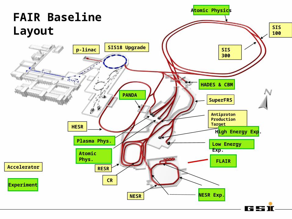
p-bar target
p-linac
Super- FRS
SIS100 SIS300
HESR
CR
RESR
Unilac
SIS 100
NESR
HESR
Antiproton Production Target
SIS18 Upgrade
CR
FAIR Baseline Layout
RESR
p-linac SIS 300
Accelerator
SuperFRSPANDA
Atomic Phys.
Plasma Phys.Low Energy Exp.
High Energy Exp.
NESR Exp.
FLAIR
Atomic Physics
HADES & CBM
Experiment

FAIR / CERN / FNAL pbar SourcesFAIR / CERN / FNAL pbar Sources
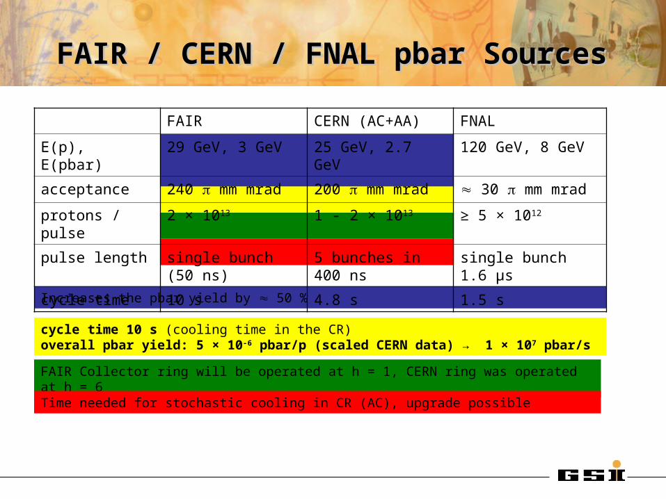
cycle time 10 s (cooling time in the CR)overall pbar yield: 5 × 10⁻⁶ pbar/p (scaled CERN data) → 1 × 10⁷ pbar/s
Increases the pbar yield by 50 %
FAIR Collector ring will be operated at h = 1, CERN ring was operated at h = 6
Time needed for stochastic cooling in CR (AC), upgrade possible
FAIR CERN (AC+AA) FNAL
E(p), E(pbar) 29 GeV, 3 GeV 25 GeV, 2.7 GeV 120 GeV, 8 GeV
acceptance 240 mm mrad 200 mm mrad 30 mm mrad
protons / pulse 2 × 10¹³ 1 - 2 × 10¹³ ≥ 5 × 10¹²
pulse length single bunch (50 ns) 5 bunches in 400 ns single bunch 1.6 µs
cycle time 10 s 4.8 s 1.5 s
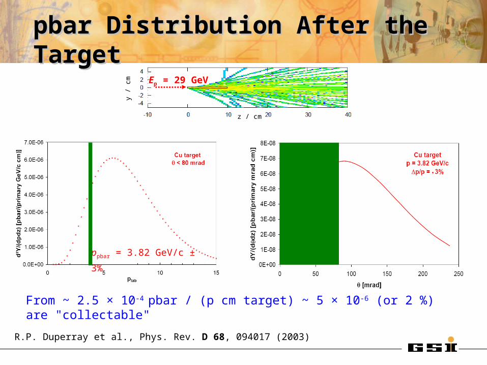
pbar Distribution After the Targetpbar Distribution After the Target
R.P. Duperray et al., Phys. Rev. D 68, 094017 (2003)
ppbar = 3.82 GeV/c ± 3%
From ~ 2.5 × 10⁻⁴ pbar / (p cm target) ~ 5 × 10⁻⁶ (or 2 %) are "collectable"
z / cm
y / c
m Ep = 29 GeV
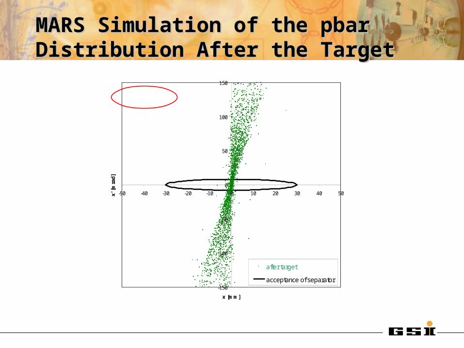
MARS Simulation of the pbar MARS Simulation of the pbar Distribution After the TargetDistribution After the Target
-150
-100
-50
0
50
100
150
-50 -40 -30 -20 -10 0 10 20 30 40 50
x [mm]
x' [
mra
d]
after target
acceptance of separator
p = 3.82 GeV/c Dp/p = ± 3%

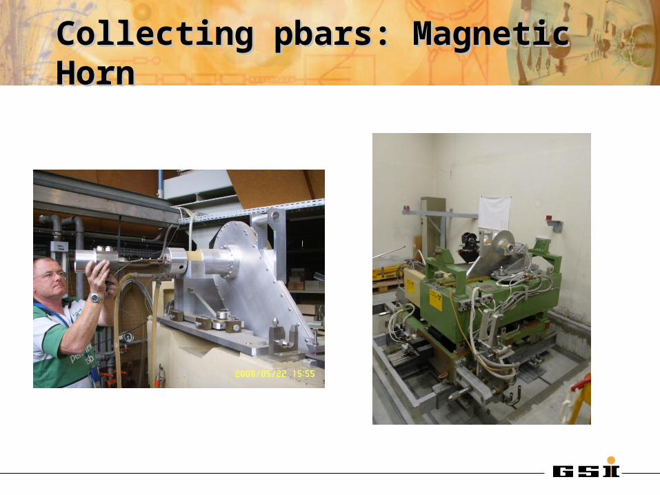
CERN ACOL Horn, I = 400 kA
Collecting pbars: Magnetic HornCollecting pbars: Magnetic Horn
target beam axis magnetic field area
Collecting pbars: Magnetic HornCollecting pbars: Magnetic Horn
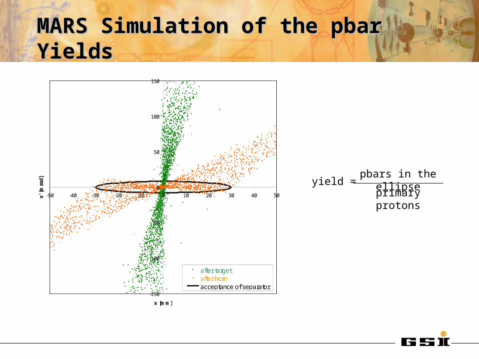
MARS Simulation of the pbar YieldsMARS Simulation of the pbar Yields
-150
-100
-50
0
50
100
150
-50 -40 -30 -20 -10 0 10 20 30 40 50
x [mm]
x' [
mra
d]
after targetafter hornacceptance of separator
p = 3.82 GeV/c Dp/p = ± 3%
yield =pbars in the ellipse
primary protons
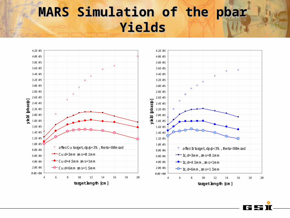
MARS Simulation of the pbar YieldsMARS Simulation of the pbar Yields
0.0E+00
2.0E-06
4.0E-06
6.0E-06
8.0E-06
1.0E-05
1.2E-05
1.4E-05
1.6E-05
1.8E-05
2.0E-05
2.2E-05
2.4E-05
2.6E-05
2.8E-05
3.0E-05
3.2E-05
3.4E-05
3.6E-05
3.8E-05
4.0E-05
4.2E-05
4 6 8 10 12 14 16 18 20
target length [cm]
yie
ld [
pb
ar/
p]
after Ir target, dp/p<3%, theta<80mrad
Ir, massive, rms=0.1mm
Ir, massive, rms=1
Ir, massive, rms=1.5
Ir: p = 1.8 b pbar=2.0 b
p
pbar
C: pbar=0.42 b
0.0E+00
2.0E-06
4.0E-06
6.0E-06
8.0E-06
1.0E-05
1.2E-05
1.4E-05
1.6E-05
1.8E-05
2.0E-05
2.2E-05
2.4E-05
2.6E-05
2.8E-05
3.0E-05
3.2E-05
3.4E-05
3.6E-05
3.8E-05
4.0E-05
4.2E-05
4 6 8 10 12 14 16 18 20
target length [cm]
yie
ld [
pb
ar/
p]
after Ir target, dp/p<3%, theta<80mrad
Ir, d=3mm, rms=0.1mm
Ir, d=4.5mm, rms=1mm
Ir, d=6mm, rms=1.5mm0.0E+00
2.0E-06
4.0E-06
6.0E-06
8.0E-06
1.0E-05
1.2E-05
1.4E-05
1.6E-05
1.8E-05
2.0E-05
2.2E-05
2.4E-05
2.6E-05
2.8E-05
3.0E-05
3.2E-05
3.4E-05
3.6E-05
3.8E-05
4.0E-05
4.2E-05
4 6 8 10 12 14 16 18 20
target length [cm]
yie
ld [
pb
ar/
p]
after Cu target, dp/p<3%, theta<80mrad
Cu d=3mm rms=0.1mm
Cu d=4.5mm rms=1mm
Cu d=6mm rms=1.5mm
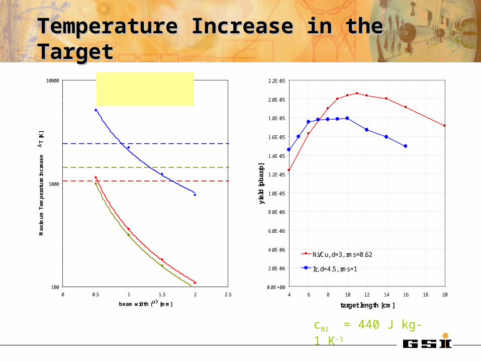
Temperature Increase in the TargetTemperature Increase in the Target
100
1000
10000
0 0.5 1 1.5 2 2.5
beam width () [mm]
Max
imu
m T
emp
erat
ure
incr
ease
D
T [
K]
DT = 360 K × w-1.68
DT = 310 K × w-1.68
DT = 2100 K × w-1.35
IrCuNi
melting of Ir
melting of Ni
melting of Cu
Fluka simulation
2×10¹³ protons per pulseGaussian beam profile
29 GeV/c, r = 1 mm ()
0.00
0.02
0.04
0.06
0.08
0.10
0 1 2 3 4 5 6
z [cm]
(dE
/dm
) max
[Ge
V/(
pri
m g
)]
Ir Cu/Ni
cIr = 130 J kg-1 K-1
cCu = 385 J kg-1 K-1
cNi = 440 J kg-1 K-10.0E+00
2.0E-06
4.0E-06
6.0E-06
8.0E-06
1.0E-05
1.2E-05
1.4E-05
1.6E-05
1.8E-05
2.0E-05
2.2E-05
4 6 8 10 12 14 16 18 20
target length [cm]
yiel
d [
pb
ar/p
]Ni/Cu, d=3, rms=0.62
Ir, d=4.5, rms=1
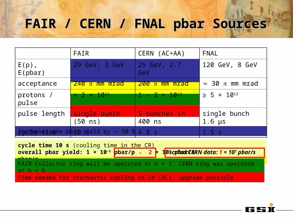
FAIR / CERN / FNAL pbar SourcesFAIR / CERN / FNAL pbar Sources
cycle time 10 s (cooling time in the CR)overall pbar yield: 5 × 10⁻⁶ pbar/p (based on CERN data) → 1 × 10⁷ pbar/s
Increases the pbar yield by 50 %
FAIR Collector ring will be operated at h = 1, CERN ring was operated at h = 6
Time needed for stochastic cooling in CR (AC), upgrade possible
FAIR CERN (AC+AA) FNAL
E(p), E(pbar) 29 GeV, 3 GeV 25 GeV, 2.7 GeV 120 GeV, 8 GeV
acceptance 240 mm mrad 200 mm mrad 30 mm mrad
protons / pulse ≥ 2 × 10¹³ 1 - 2 × 10¹³ ≥ 5 × 10¹²
pulse length single bunch (50 ns) 5 bunches in 400 ns single bunch 1.6 µs
cycle time 10 s 4.8 s 1.5 s
cycle time 10 s (cooling time in the CR)overall pbar yield: 1 × 10⁻⁵ pbar/p → 2 × 10⁷ pbar/s scaled CERN data: 1 × 10⁷ pbar/s
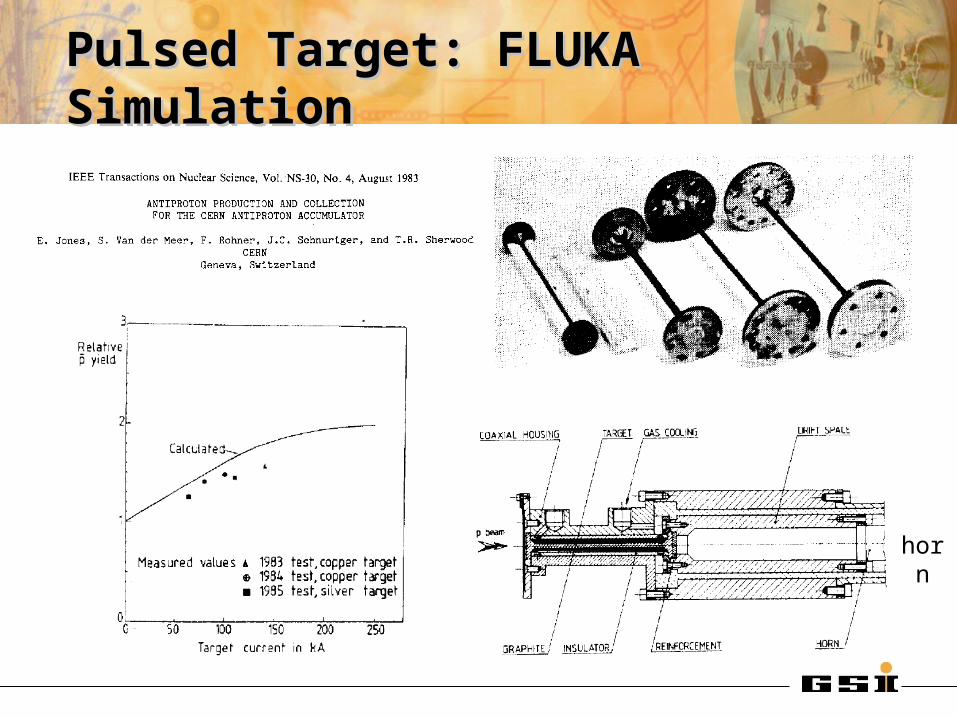
Pulsed Target: FLUKA SimulationPulsed Target: FLUKA Simulation
horn
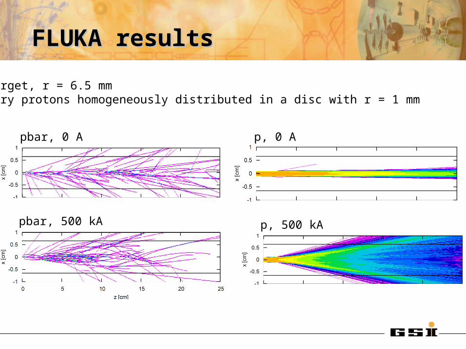
FLUKA results FLUKA results
pbar, 0 A
pbar, 500 kA
p, 0 A
p, 500 kA
Cu target, r = 6.5 mmprimary protons homogeneously distributed in a disc with r = 1 mm

FLUKA resultsFLUKA results
It is likely that FLUKA overestimates the production cross section. Therefore, the absolute yields might be a factor 2 to high.
0E+00
1E-05
2E-05
3E-05
4E-05
5E-05
6E-05
0 5 10 15 20 25 30
target length [cm]
pb
ar/p
Cu, r_t=6.5mm, r_beam=1mm, 0A
Cu, r_t=6.5mm, r_beam=1mm, 500kA
Cu, r_t=1.5mm, r_beam=1mm, 0A
Cu, r_t=1.5mm, r_beam=1mm, 500kA
Cu, r_t=1.5mm, r_beam=1mm, 150kA
Cu, r_t=1.5mm, r_beam=0.01mm, 150kA
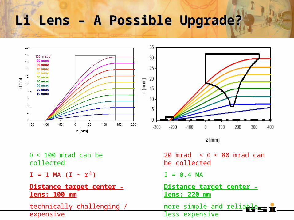
Li Lens – A Possible Upgrade?Li Lens – A Possible Upgrade?
< 100 mrad can be collected
I = 1 MA (I ~ r²)
Distance target center - lens: 100 mm
technically challenging / expensive
20 mrad < < 80 mrad can be collected
I = 0.4 MA
Distance target center - lens: 220 mm
more simple and reliable, less expensive
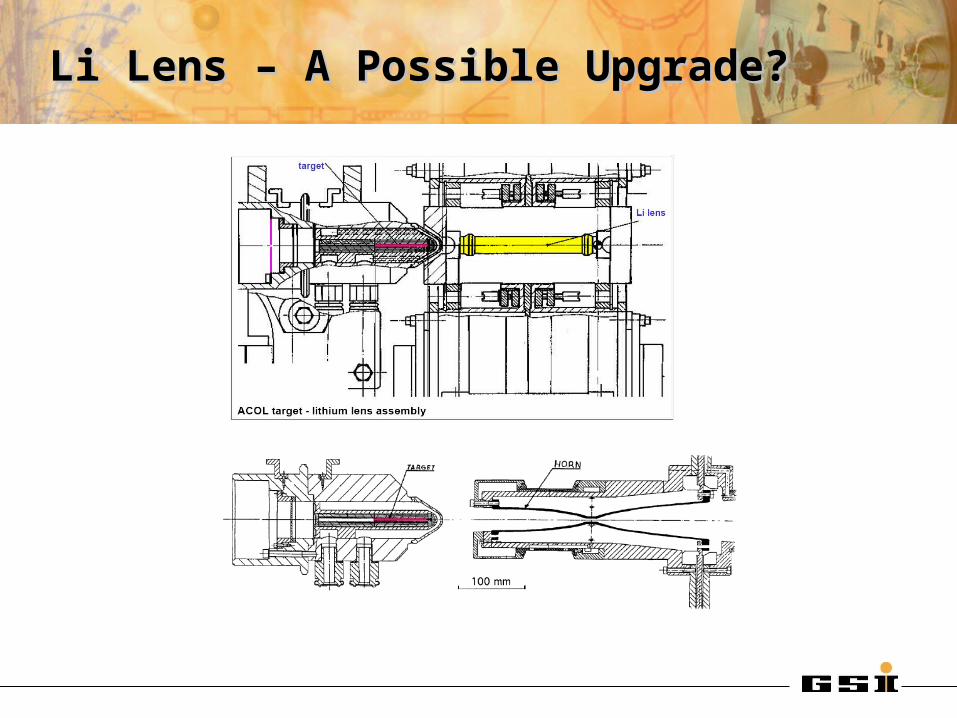
Li Lens – A Possible Upgrade?Li Lens – A Possible Upgrade?

Li Lens – A Possible Upgrade?Li Lens – A Possible Upgrade?
Ir, d=3mm, rms=0.1mm
0.0E+00
2.0E-06
4.0E-06
6.0E-06
8.0E-06
1.0E-05
1.2E-05
1.4E-05
1.6E-05
1.8E-05
2.0E-05
2.2E-05
2.4E-05
2.6E-05
2.8E-05
3.0E-05
4 6 8 10 12 14 16 18 20
target length [cm]
yie
ld [
pb
ar/
p]
Ir, d=3mm, rms=0.1mm
Li Lens, d = 36 mm, I = 1.0 MA
0.0E+00
2.0E-06
4.0E-06
6.0E-06
8.0E-06
1.0E-05
1.2E-05
1.4E-05
1.6E-05
1.8E-05
2.0E-05
2.2E-05
2.4E-05
2.6E-05
2.8E-05
3.0E-05
4 6 8 10 12 14 16 18 20
target length [cm]
yie
ld [
pb
ar/
p]
Ir, d=3mm,rms=0.1mm
Horn, I = 0.4 MA

Li Lens – A Possible Upgrade?Li Lens – A Possible Upgrade?
0.0E+00
2.0E-06
4.0E-06
6.0E-06
8.0E-06
1.0E-05
1.2E-05
1.4E-05
1.6E-05
1.8E-05
2.0E-05
2.2E-05
2.4E-05
2.6E-05
2.8E-05
3.0E-05
4 6 8 10 12 14 16 18 20
target length [cm]
yie
ld [
pb
ar/
p]
Ir, d=3mm, rms=0.1mm
Ni, d=3mm, rms=0.62mm
Li Lens, d = 36 mm, I = 1.0 MA
0.0E+00
2.0E-06
4.0E-06
6.0E-06
8.0E-06
1.0E-05
1.2E-05
1.4E-05
1.6E-05
1.8E-05
2.0E-05
2.2E-05
2.4E-05
2.6E-05
2.8E-05
3.0E-05
4 6 8 10 12 14 16 18 20
target length [cm]
yie
ld [
pb
ar/
p]
Ir, d=3mm, rms=0.1mm
Ni, d=3mm, rms=0.62mm
Horn, I = 0.4 MA

Li Lens – A Possible Upgrade?Li Lens – A Possible Upgrade?
0.0E+00
2.0E-06
4.0E-06
6.0E-06
8.0E-06
1.0E-05
1.2E-05
1.4E-05
1.6E-05
1.8E-05
2.0E-05
2.2E-05
2.4E-05
2.6E-05
2.8E-05
3.0E-05
4 6 8 10 12 14 16 18 20
target length [cm]
yie
ld [
pb
ar/
p]
Ir, d=3mm, rms=0.1mm
Ni, d=3mm, rms=0.62mm
Ir, d=4.5mm, rms=1mm
Li Lens, d = 36 mm, I = 1.0 MA
0.0E+00
2.0E-06
4.0E-06
6.0E-06
8.0E-06
1.0E-05
1.2E-05
1.4E-05
1.6E-05
1.8E-05
2.0E-05
2.2E-05
2.4E-05
2.6E-05
2.8E-05
3.0E-05
4 6 8 10 12 14 16 18 20
target length [cm]
yie
ld [
pb
ar/
p]
Ir, d=3mm, rms=0.1mm
Ni, d=3mm, rms=0.62mm
Ir, d=4.5mm, rms=1mm
Horn, I = 0.4 MA
Experimental data from CERN:A 36 mm/1.3 MA lens gave a 30% higher yield (with
nominal production beam) compared to a 0.4 MA horn.(with a target optimized for the Li lens)
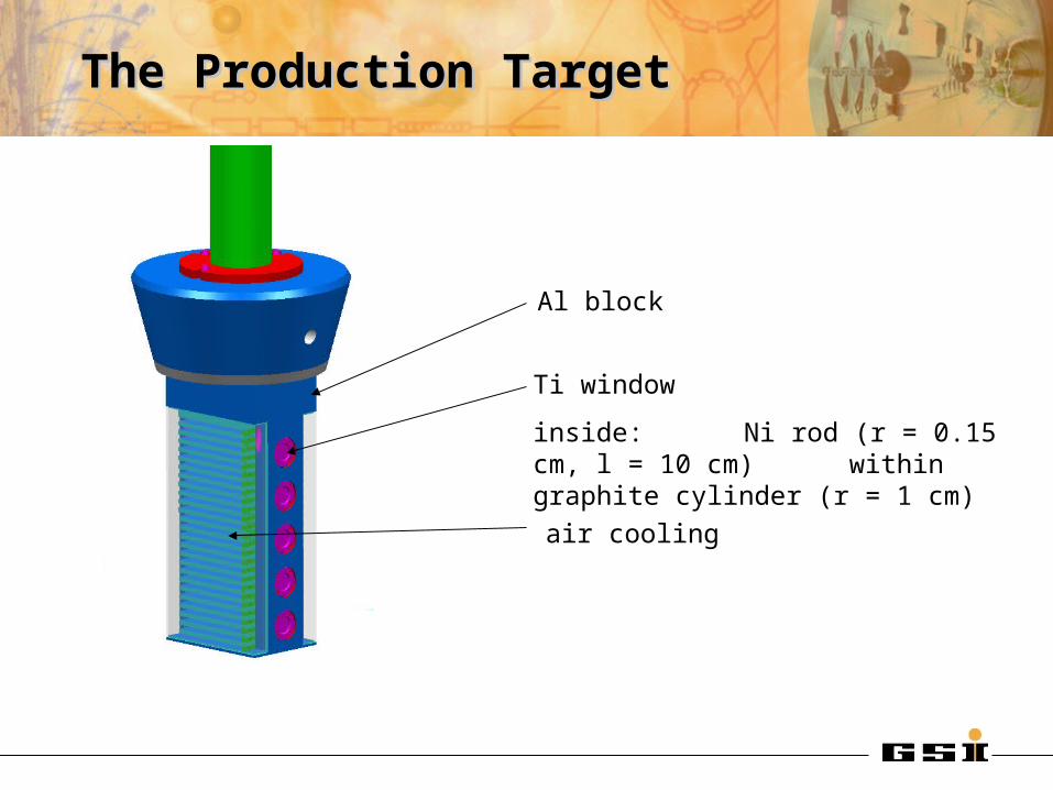
The Production TargetThe Production Target
Al block
Ti window
inside: Ni rod (r = 0.15 cm, l = 10 cm) within graphite cylinder (r = 1 cm)
air cooling
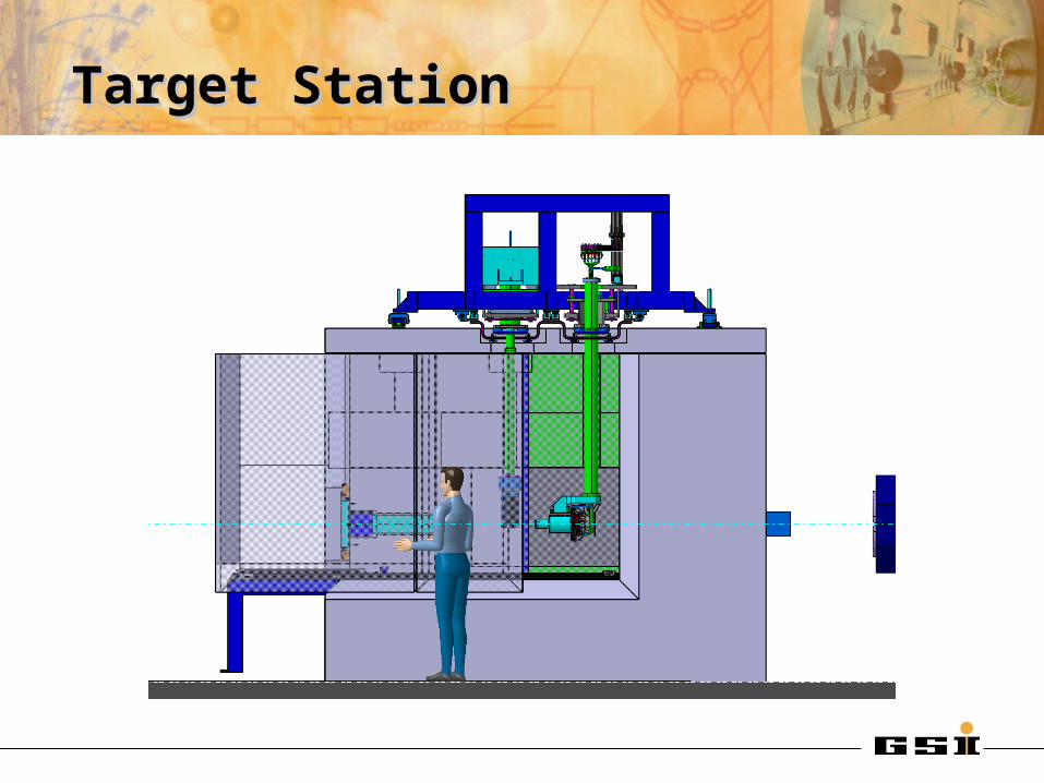
Target StationTarget Station
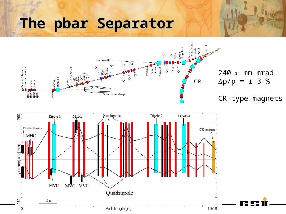
The pbar SeparatorThe pbar Separator
240 mm mradDp/p = ± 3 %
CR-type magnets

Pbar Target Building: Horizontal CutPbar Target Building: Horizontal Cut
8 m
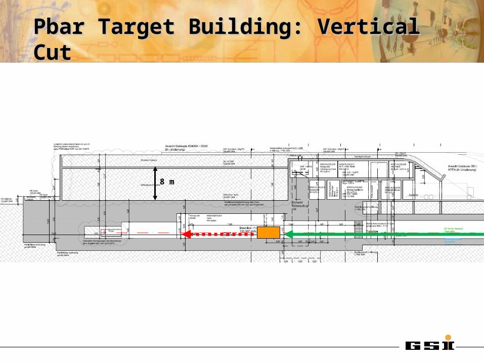
Pbar Target Building: Vertical CutPbar Target Building: Vertical Cut
8 m
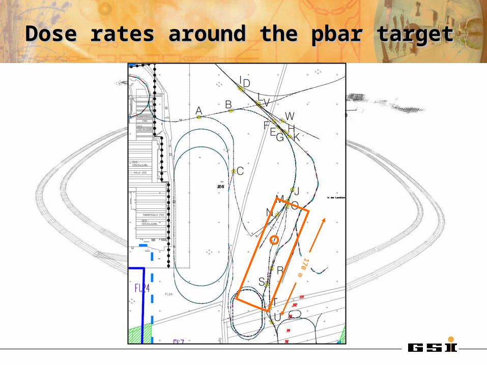
Dose rates around the pbar targetDose rates around the pbar target
170 m
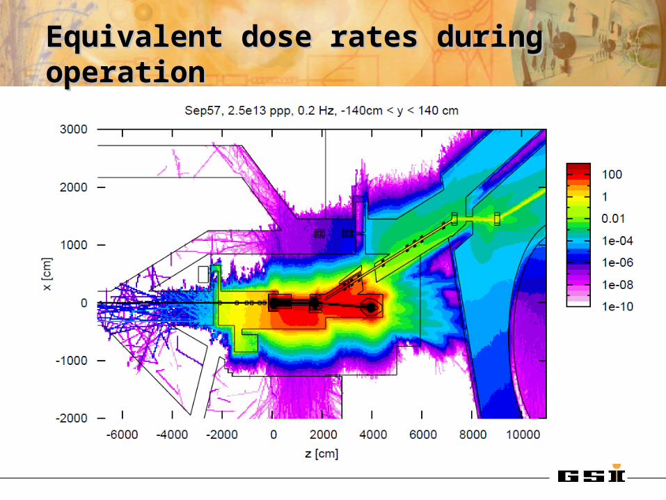
Equivalent dose rates during operationEquivalent dose rates during operation
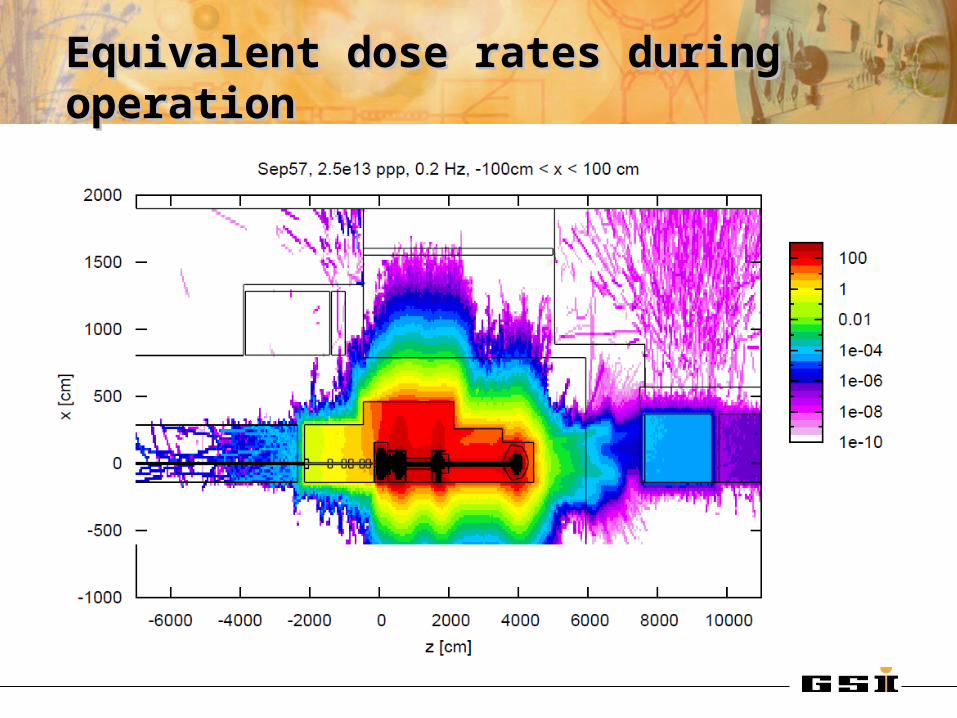
Equivalent dose rates during operationEquivalent dose rates during operation

Equivalent dose rates during operationEquivalent dose rates during operation
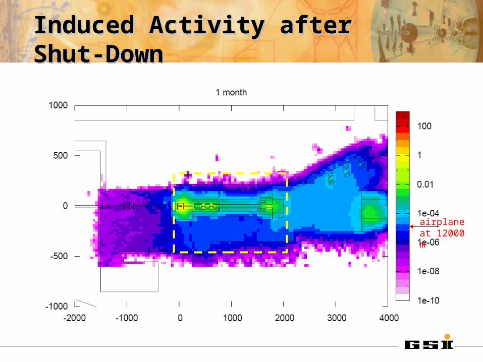
Induced Activity after Shut-DownInduced Activity after Shut-Down
airplane at 12000 m
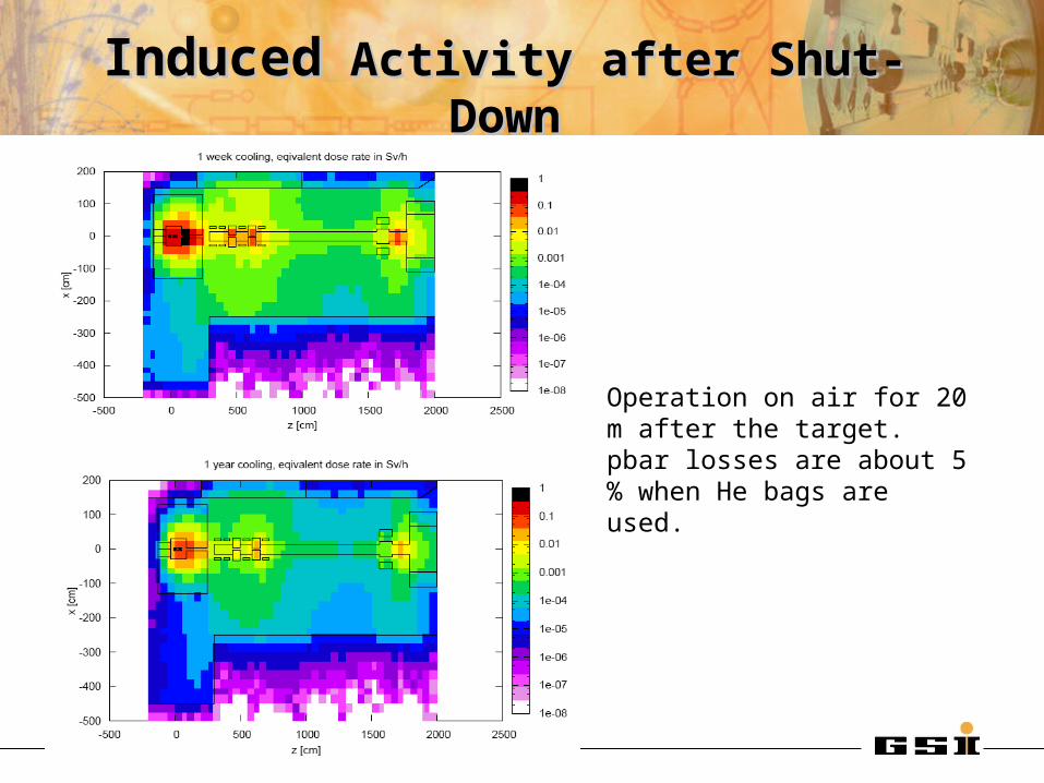
InducedInduced Activity after Shut-Down Activity after Shut-Down
Operation on air for 20 m after the target.pbar losses are about 5 % when He bags are used.

Target Exchange (target on air!)Target Exchange (target on air!)
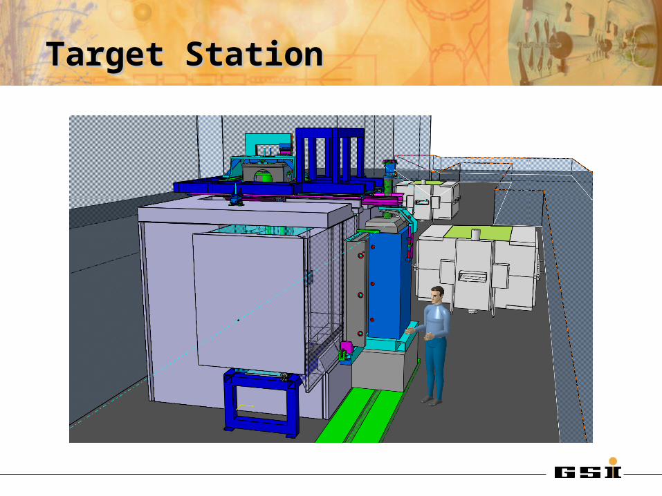
Target StationTarget Station
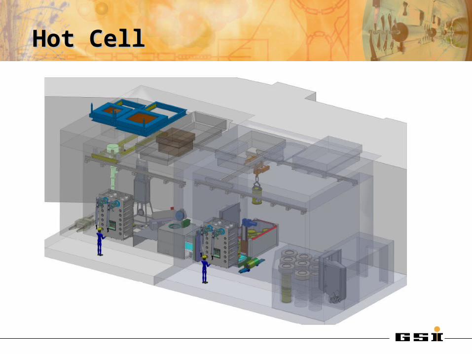
Hot CellHot Cell
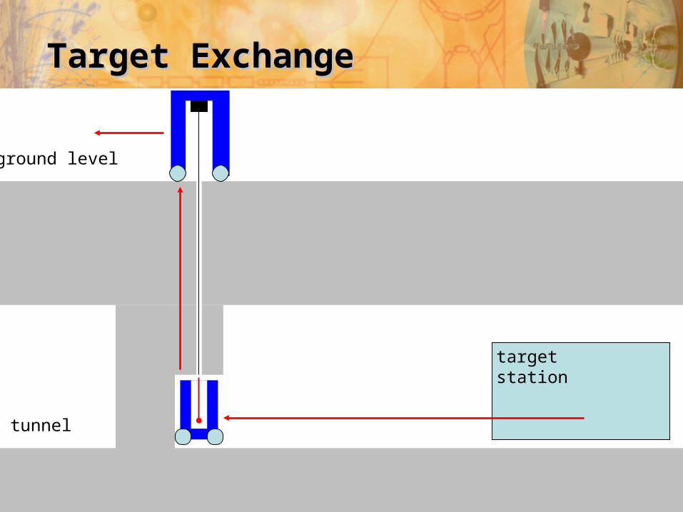
Target ExchangeTarget Exchange
target station
tunnel
ground level
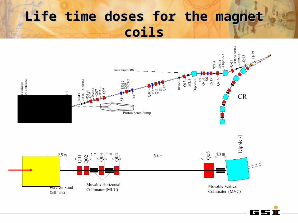
Life time doses for the magnet coilsLife time doses for the magnet coils

Life time doses for the magnet coilsLife time doses for the magnet coils
20 MGy 50 MGy
50 MGy
Polyimide insulation required
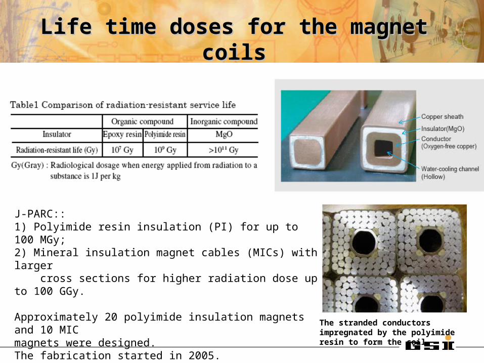
Life time doses for the magnet coilsLife time doses for the magnet coils
J-PARC::1) Polyimide resin insulation (PI) for up to 100 MGy;2) Mineral insulation magnet cables (MICs) with larger cross sections for higher radiation dose up to 100 GGy.
Approximately 20 polyimide insulation magnets and 10 MICmagnets were designed. The fabrication started in 2005.
The stranded conductors impregnated by the polyimide resin to form the coil