status of smr development and deployment of smrs in the ... · construction time. rated capacity ....
TRANSCRIPT

Status of SMR development and deployment of SMRs in the Russian Federation
V.M. Belyaev, A.N. Pakhomov, K.B. Veshnyakov
Second Meeting of the Technical Working Group for Small and Medium-sized or Modular Reactor (TWG-SMR)
Vienna, 8-11 July 2019

> >>
2
OKBM Reactor Technologies: Experience and DevelopmentExperience is the best of all evidences –
F. Bacon
•Proven reactor technologies and innovation solutions are available.
Foundation of proven technologies and development
•Total number of reactor plants is 20 pcs. (including 7 RPsinstalled on the acting nuclear icebreakers).•60 years of 3 generations of nuclear icebreakers operation in theArctic region.•Total operating time is more than 400 reactor-years.•Six innovation RITM-200 RPs have been supplied for the threemultipurpose nuclear icebreaker.
•Two RPs have been supplied for the FNPP “AcademicianLomonosov” confirming the efficiency of combining thefunctions of Chief Designer and Complete Supplier of KLT-40SRP.
Key fields of activities:•Standardization of engineering decisions for the entire powerrange;•Increase of reliability, safety, manoeuvrability;•Reduction of the scope of maintenance, increase of serviceoperation between repairs.
Experience in development and fabrication of reactor plants for the floating nuclear
power plants
Great experience in development and operationof nuclear icebreakers reactor
plants
Great experience in development and operation of marine reactor plants

> >>
3
Floating NPP Based on FPU with KLT-40S RPs
Product Electric power 20…70 MWHeat 50…146 Gcal/h
Reactor plant KLT-40SNumber of RPs 2 unitsElectric power 2х35 MWTime interval between refueling 2.5-3 yearsOperating time 40 years
New class of power sources
Site• Distant or isolated regions (Pevek town – site for first of
a kind NPP)
Pilot design of Small NPP• FPU trials are complete• NPP start up is scheduled for 2019 - 2020
Competitive advantages• Compactness• High maneuverability• Prefabrication
The power unit comprises two reactor plants, two turbine plants, electric-power system, refueling complex, nuclear fuel and radioactive waste storage, accommodations.
An autonomous power unit is mounted on the non-self-propelled barge. The number of offshore facilities and requirements for them are minimal.
The power unit is supplied to the operation site by water on a turnkey basis after completed acceptance tests.
After completion of four cycles, it is transported to a specialized enterprise to be repaired.
It is possible to change the power unit location site. After decommissioning on termination of the service life, the
floating power unit is transported to its disposal site providing retention of the “green lawn” state in the floating NPP operation area.

> >>
4
New Generation of Nuclear Icebreakers.Multi-purpose Nuclear Icebreaker with RITM-200 RPs
RP thermal capacity 2х175 MWPropulsion capacity 60 MWDisplacement 33 530/ 25 540 tDraft 10.5 /8.55 mIcebreaking capability 2.8 m
Commissioning schedule:“Arctica” 2020“Sibir” 2021“Ural” 2022Two additional multi-purpose nuclear icebreakers are planning

> >>
5
RITM-400 RP for nuclear leader icebreaker
Icebreaker’s purpose: Year-round escort of large-capacity vessels and caravans in the Arctic
Icebreaker’s tasks:1. Providing year-round traffic on the Northern Sea Route regardless of weather and ice
conditions.2. Ensuring year-round export of hydrocarbons from the Yamal deposits to the countries
of the Asia-Pacific region.
Key features of leader icebreaker:• Propulsion capacity - 120 MW; • Icebreaking capability - up to 4 m;• Displacement - 70 600 t;• Length - 209.0 m;• Beam - 47.5 m;• Draft - 13.0 m;• Speed through ice 2 m thick - 13 knots.• Icebreaker start up is scheduled for - 2027Two additional icebreakers are planning

> >>
6
Small Land-Based NPP with Two RITM-200 RPs
Reactor plant RITM-200 Number of RPs 2 unitsElectric power 2х52,5 MWTime interval between refueling 6 yearsOperating time 60 yearsTotal site area 6 ha
First of a kind2027
Small nuclear station based on ship technologiesCompetitive advantagesMinimum construction site;Long-term operation without refueling;High maneuverability
Status: Conceptual Design
Basis for RITM-200 applicationCompleted design documentation and production equipmentProved fabrication technologiesEstablished enterprise cooperation
• RITM-200 reactor plant of multi-purpose nuclear icebreaker was applied as a basic power source;• The highest technical and economic indices and efficiency were achieved due to ship approaches (compactness, maneuverability, resistance to external impacts, developed self-protection properties);• Meeting all current global requirements and trends in nuclear facility safety area;
Product Electric powerRated capacity 105 MW
> >>
7
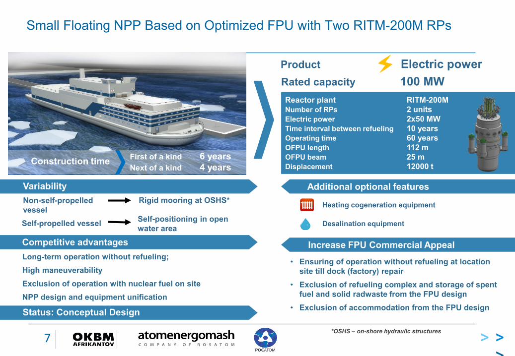
Small Floating NPP Based on Optimized FPU with Two RITM-200M RPs
Product Electric power
Heating cogeneration equipment
Reactor plant RITM-200MNumber of RPs 2 unitsElectric power 2х50 MWTime interval between refueling 10 yearsOperating time 60 yearsOFPU length 112 mOFPU beam 25 mDisplacement 12000 t
Non-self-propelled vessel
Rigid mooring at OSHS*
Self-positioning in open water areaSelf-propelled vessel
First of a kind 6 yearsNext of a kind 4 yearsConstruction time
Rated capacity 100 MW
Desalination equipment
Additional optional features
Long-term operation without refueling;High maneuverabilityExclusion of operation with nuclear fuel on siteNPP design and equipment unification
Status: Conceptual Design
Variability
Increase FPU Commercial Appeal• Ensuring of operation without refueling at location
site till dock (factory) repair• Exclusion of refueling complex and storage of spent
fuel and solid radwaste from the FPU design• Exclusion of accommodation from the FPU design
*OSHS – on-shore hydraulic structures
Competitive advantages

> >>
8
KLT-40S, RITM-200, RITМ-200M and RITM-400 RP. Comparative Characteristics
Characteristic KLT-40S RITM-200 RITM-200М RITM-400
Total assigned service life, h/year 300 000/40 500 000/60 480 000/60 320 000/40Assigned life time/service life till factory repair, h/years 100 000/12 250 000/30 160 000/20 160 000/20
Number of medium repairs 2 1 2 1Mass of two RPs in the containment, t 3743 2200 2600 3890Containment dimensions for two RPs LхWхH, m 12х17.2х12 6х13.2х15.5 6.8х14.6х16.0 8.96х18.2х17.5
Core refueling interval, years 2.5 (3.0) 5.7 10 5.7RCP power, kW 4х152 4х97 4х97 4х235Passive heat removal, h 24 ∞ ∞ ∞
Time until core uncovery in a passive accident scenario with primary leakage, h
10 72 72 12.7

> >>
9
Arrangement of KLT-40S, RITM-200, RITM-200M and RITM-400 RP in the Containment
RITM-200MKLT-40S
RP weight in the containment – 1870 tRP dimensions in the
containment –12 х 7.9 х 12 m
RP weight in the containment – 1300 tRP dimensions in the
containment –6.8 х 6.7 х 16.0 m
RITM-200
RP weight in the containment – 1100 tRP dimensions in the
containment –6 х 6 х 15.5 m
RITM-400
RP weight in the containment – 1945 tRP dimensions in the
containment –9 х 8.2 х 17.5 м

> >>
10
RITM-200М RP. Main Engineering Solutions
1. The RP has integral design of the reactor with forced circulation of the primary coolant and remote gas pressure compensation system.2. Composition and structure of the RP systems are designed considering experience gained while developing the previous plant generation, requirements of the up-to-date norm safety documentation, ToR requirements with regard to weight-dimensional characteristics and reduction of liquid radwaste. 3. The main design approach is rational combination of passive and active safety means and trains, optimal use of the normal operational and safety systems.
Passive pressure reduction and cooling down systems are introduced (efficiency of the systems is confirmed by bench testing);Pressure compensation system is divided in two independent groups to minimize diameter of coolant leak;Main circulation path of the primary circuit is located in a single vessel;Header scheme of primary coolant circulation is introduced, which ensures advanced vitality of the plant during SG and MCP failures.

> >>
11
Safety Provision by Active Systemsin Loss-of-Heat-Removal Accidents
Active Residual Heat Removal
1 safety loop through steam generator 1 safety loop through heat exchanger of
primary circuit coolant purification loop Each train provides heat removal from the core
to the heat sink with account of single point of failure.
BDBA management is performed by water supply from condensate-feeding system of steam-turbine plant.
Actuation Automatically by emergency protection
signals Remotely by operator from central control
panel From local post
Ultimate heat sink
Pump of the 4th circuit
Pump of the
4th circuitCondensate pump
Pump of the 3d circuit
Train of emergency cooldown
through SG
Train of cooldown
through HX of 1-3
circuits
CT
PC
ET
HX
HX
CCP
CCP3d
circuit
EFP
MCP-1 MCP-1
SG SG
Ultimate heat sink

> >>
12
Safety Provision by Passive Systemsin Loss-of-Heat-Removal Accidents
to surrounding air to surrounding airECD tank
ECD tank
AHX
draw tube
ECDS HX ECDS HX
AHX
draw tube
SG SG
MCP-1 MCP-1Passive Residual Heat Removal
2 safety loops with coolant circulation from water tanks through steam generators. Evaporated water condenses in air-to-water heat exchangers and flow back to tanks
Each train provides heat removal from the core to the heat sink with account of single point of failure.
Safety provision using passive means for not less than 3 days
BDBA management is performed by water supply from condensate-feeding system of steam-turbine plant.
Actuation
Automatically by blackout signals; Remotely by operator from central
control panel; From local post; From hydraulically-controlled air
control valve by direct impact of emergency primary circuit pressure
> >>
13
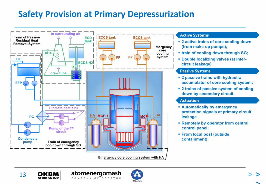
Safety Provision at Primary Depressurization
Train of Passive Residual Heat
Removal System
to surrounding airECD tank
AHX
draw tube
ECDS HX
Emergency core cooling system with HA
Ultimate heat sink
Pump of the 4th
circuit
Train of emergency cooldown through SG
Condensate pump
PC
CT
EFP
ECCS tank ECCS tank
FP FP
Emergency core
cooling system
HA MCP-1 MCP-1 HA
Active Systems 2 active trains of core cooling down
(from make-up pumps); train of cooling down through SG; Double localizing valves (at inter-
circuit leakage).Passive Systems 2 passive trains with hydraulic
accumulator of core cooling system; 2 trains of passive system of cooling
down by secondary circuit.Actuation Automatically by emergency
protection signals at primary circuit leakage Remotely by operator from central
control panel; From local post (outside
containment);

> >>
14
Safety Provision at Overpressure in Containment
14
Emergency cooling down tank Water to coolant system Steam to
atmosphere
Water from coolant system
Steam-water
mixture Heat exchanger of heat removal system
Containment
Makeup
Equipment room
Reactor compartment
Makeup
Localizing valves
Safety device
Passive Means 2 passive trains to decrease emergency pressure in
containment; Localization of stem-water mixture in LOCA within
containment of emergency reactor plant; Integration of containment into united space due to safety
device actuation.
Actuation Automatically by emergency protection signals at primary
circuit leakage Remotely by operator from central control panel; From local post

> >>
15
Radiation and Environmental Safety
POPULATION RADIATION DOSE RATE UNDER NORMAL OPERATION CONDITIONS AND DESIGN –BASIS ACCIDENTS DOES NOT EXCEED 0.01% OF NATURAL RADIATION BACKGROUND
POPULATON IS ALLOWED TO LIVE IN THE PROTECTIVE ACTION PLANNING AREA.NO COMPULSORY EVACUATION PLANNING AREA
1 km
BUFFER AREAPROTECTIVE ACTION
PLANNING AREA

> >>
16
Conclusion
JSC “Afrikantov OKBM” has developed and is implementing innovative Reactor plant designs enabling to create a power range of NPPs of various applications and arrangements.
The designs provide high technical-and-economic indices, referentiality of the applied technical solutions and their safety is well substantiated and confirmed by many years operation of analogues and prototypes.
RITM-200 type reactor plant has advantages from the viewpoint of safety, weight-size parameters and technical-and-economic indices.

> >>
17
THANK YOU FOR YOUR ATTENTION!