static and dynamic testing of steel wire mesh … · saimm, sanire and isrm 6th international...
TRANSCRIPT

SAIMM, SANIRE and ISRM
6th
International Symposium on Ground Support in Mining and Civil Engineering Construction
J R. Player, E C Morton, A G Thompson and E Villaescusa
Page 693
STATIC AND DYNAMIC TESTING OF STEEL WIRE MESH FOR MINING
APPLICATIONS OF ROCK SURFACE SUPPORT
J R. Player, E C Morton, A G Thompson and E Villaescusa
CRC Mining / WA School of Mines Kalgoorlie, Western Australia
ABSTRACT
Wire mesh has been used for surface ground support in mining since the 1950s.
Experimental studies have been conducted throughout the world. The response of the mesh is
dependant on the sample size, the boundary restraint systems and the loading conditions.
The Western Australian School of Mines (WASM) has developed a facility for the static
testing of ground support elements. The static facility consists of several stiff steel frames
used to support the sample and a screw feed jack used to load the sample. The sample is
restrained on all sides and displaced at a constant rate by a screw feed jack. Instrumentation
measures the displacement and the load being applied.
The WASM dynamic test facility has been recently modified to enable the testing of surface
support elements. Surface support element testing at the dynamic test facility will be
conducted using sample sizes and boundary conditions similar to the static testing facility to
enable the comparison of results between the two facilities.
Two testing programs have been undertaken to assess the static and dynamic performance of
welded wire and chain link mesh. The results of the test programs are presented and
comparisons are made for the performance of the two types of mesh.
1 INTRODUCTION
It has been recognised for many years that underground mining within Western Australia is
progressing to greater depths and the influence of stress on the mining environment is
becoming more pronounced. Seismicity, stress related rock mass degradation and the
associated ground support problems are becoming more common. Accordingly it is
becoming increasingly important to understand the response of ground support to both static
and dynamic loading conditions.
Stress related rock mass damage impacts considerably on ground conditions within many
West Australian mines. This increases the need for effective areal surface support between
rock reinforcement elements. Wire mesh is currently the most popular surface support
element used in Western Australia.
Wire mesh has been used as surface support in mining since the 1950s. Many forms of mesh
are used including welded wire mesh, expanded metal mesh and woven (chain link) mesh. In
the early 1980s, mesh research was undertaken in South Africa by Rand Mines limited
(Ortlepp, 1983) and by the Ontario Ministry of Labour in Canada (Pakalnis and Ames, 1983).
In the 1990s, Ortlepp continued his work, progressing to dynamic testing. Tannant et al 1997
and Thompson et al 1999 both conducted large scale mesh tests to determine the force -
displacement reaction properties of the given mesh being tested.
In 2002 the Western Australian school of Mines designed the dynamic test facility to test
reinforcement elements (Player et al., 2004). Recent modifications to the test facility have
been undertaken to enable testing of surface support elements.
In 2005, the Western Australian School of Mines designed and built a large scale static
testing facility to complement the dynamic test facility (Morton et al., 2007).

SAIMM, SANIRE and ISRM
6th
International Symposium on Ground Support in Mining and Civil Engineering Construction
J R. Player, E C Morton, A G Thompson and E Villaescusa
Page 694
Two test programs were undertaken to assess the static and dynamic properties of welded
wire and chain link meshes.
The results from the test programs are presented and the static and dynamic performances of
each of the mesh types are compared.
2 TEST FACILITIES
2.1 Static Test Facility
The WASM static test facility has been described by Morton et al. (2007) and is shown in
Figure 1. The facility comprises two steel frames; a lower frame used to support the sample
and an upper frame to provide loading reaction. The mesh sample is restrained within a stiff
frame that rests on the support frame. The restraint system consists of high strength threaded
bar, eye nuts and D shackles passing through a perimeter frame at allocated points (Figure 2).
Figure 1: Static test facility
Figure 2: Boundary restraint system

SAIMM, SANIRE and ISRM
6th
International Symposium on Ground Support in Mining and Civil Engineering Construction
J R. Player, E C Morton, A G Thompson and E Villaescusa
Page 695
A screw feed jack is mounted on the reaction frame. The screw feed jack is driven at a
constant speed (4mm per minute) and allows large displacements to be imposed on the mesh.
Load is applied to the mesh through a spherical seat, to a 300mm square, thick steel plate.
The force is measured using a 50 tonne load cell mounted between the screw feed shaft and
the spherical loading point. Data acquisition is undertaken at a rate of 2 samples per second.
Testing of a sample can take up to an hour to complete.
2.2 Dynamic Test Facility
The dynamic test facility has been described in detail by Player et al. (2004) and is shown in
Figure 3. The test facility consists of a drop beam positioned between four guide rails.
Samples are loaded using the momentum transfer concept. A frame, to support the mesh, is
bolted to the drop beam. The mesh is held in place using threaded bar, shackles and eye bolts
in the same configuration as the standard static test arrangement. A loading mass is placed
into the centre of the restrained mesh. The loading mass consists of a pyramid shaped bag
filled with a known mass of steel balls (0.5 or 1 tonne). The loading area of the bag is
650mm x 650mm. A wooden prop is placed between the loading mass and the drop beam to
prevent the mass “floating” during the initial free fall period. The drop beam and attached
mesh frame assembly are dropped from a specific height to generate dynamic loading on the
mesh sample.
Drop beam
Buffer
Loading Mass
Mesh frame
Helicopter release
Drop beam
Buffer
Loading Mass
Mesh frame
Helicopter release
Figure 3: Dynamic test facility

SAIMM, SANIRE and ISRM
6th
International Symposium on Ground Support in Mining and Civil Engineering Construction
J R. Player, E C Morton, A G Thompson and E Villaescusa
Page 696
Computer software, advanced instrumentation and a high speed video camera are used to
record the test data. Data acquisition is undertaken at a rate of 25000 samples per second per
channel. Testing is completed in a second. Data processing is undertaken after the test to
determine the dynamic performance of the test sample.
3 MESH SAMPLES
Testing has been undertaken on two different mesh types (Figure 4). The standard welded
wire mesh used in Western Australian mines comprises 5.6mm diameter galvanised wires
welded to form a 100mm square grid pattern.
The second type of mesh is 4mm diameter high strength steel wire chain link mesh provided
by Geobrugg. Wires are shaped in a zigzag pattern and are then woven together to form a
diamond grid pattern. The wires are joined at the ends using a specially designed process.
A 1.3m x 1.3m sample size is tested in both facilities. The welded wire mesh samples were
cut from larger sheets provided by various sponsors. The chain link samples were
specifically manufactured by Geobrugg to size for testing purposes.
Figure 4: Chain link and welded wire mesh respectively
The welded wire mesh samples are cut from larger sheets (3m x 2.4m). The cross wires are
marked so the sample can be placed within the mesh frame using a known configuration. All
samples were positioned with the cross wires oriented across the frame and upwards, in
contact with the loading plate.
The chain link samples were oriented with the direction of the stiff wires stretching across the
frame.
4 RESULTS
In the assessment of any ground support system, the displacement, force and energy must be
assessed in relation to the expected rock mass demand. Villaescusa et al. (2008) suggest that
high energy absorption or large displacement capabilities may not necessarily be beneficial in
controlling dynamic ground movement. The energy absorption is a function of force and
displacement. Displacement is influenced, some times significantly, by the number of
failures within the sample. For this reason, analysis of the mesh types has been undertaken at
rupture. Rupture is defined as the point at which a part of the system breaks. Rupture may or
may not correspond to the peak force achieved during the test. The variability of the sample
response after rupture has occurred means detailed analysis cannot be achieved. Some post
peak analyses have been attempted for both the static and dynamic data but are not presented.

SAIMM, SANIRE and ISRM
6th
International Symposium on Ground Support in Mining and Civil Engineering Construction
J R. Player, E C Morton, A G Thompson and E Villaescusa
Page 697
4.1 Static Results
Typical static force - displacement response for welded wire mesh and chain link mesh are
shown in Figure 5. A summary of all the static force - displacement results is shown in
Figure 6.
0
20
40
60
80
100
120
140
160
0 100 200 300
Displacement at loading point (mm)
Force (kN
)
Weld Mesh
Chain Link Mesh
Figure 5: Typical static force – displacement response for welded wire mesh and chain link
mesh

SAIMM, SANIRE and ISRM
6th
International Symposium on Ground Support in Mining and Civil Engineering Construction
J R. Player, E C Morton, A G Thompson and E Villaescusa
Page 698
0
20
40
60
80
100
120
140
160
0 100 200 300 400
Central Displacement at Rupture (mm)
Rupture F
orce (kN
)
Weld Mesh Static
Chain Link Static
Figure 6: Summary of static force - displacement results for welded wire mesh and chain link
mesh
The average static rupture displacement for welded wire mesh is 186mm whereas the average
static rupture displacement of chain link mesh is 307mm.
Variations were observed in initial tension of the chain link mesh samples at the beginning of
each test. This was taken into account by measuring the displacement of the mesh due to the
placement of the loading plate before the commencement of a test. Highly tensioned sheets
had minimal displacement whereas loose sheets displaced significantly as a result of the
placement of the loading plate. The initial tension did not appear to have a significant effect
on the overall force - displacement response of the mesh.
The average static rupture force for welded wire mesh is 44kN. The average static rupture
force for chain link mesh is 145kN.
Significant differences were observed in the failure mechanisms and their locations between
welded wire mesh and chain link mesh. The rupture of welded wire mesh always occurred at
the boundary on a directly loaded wire. This is a function of the stiff boundary conditions
used for testing. The failure mechanism of welded wire mesh, on the other hand, is a measure
of the mesh quality. Three different welded wire mesh failure mechanisms were observed
(Figure 7); tensile wire failure, weld failure and failure of the wire through the heat affected
zone (HAZ). Tensile failure of the wire occurs when the weld strength is more than the
strength of the wire.

SAIMM, SANIRE and ISRM
6th
International Symposium on Ground Support in Mining and Civil Engineering Construction
J R. Player, E C Morton, A G Thompson and E Villaescusa
Page 699
Figure 7: Welded wire mesh failure mechanisms; L – R tensile wire failure, weld failure and
failure of the wire through the HAZ
For chain link mesh only one failure mechanism was observed. The chain link mesh failed
on the edge of the plate (Figure 8), either as a result of the plate cutting through the wires or
as a result of the wires cutting each other at a “link”. This failure mechanism limits the direct
applicability of the test and causes some variability in the results. Generally only one or two
wires broke. The load dropped completely after the first rupture as a result of plate movement
and the test was stopped. This was not considered complete destruction of the mesh.
Figure 8: Chain link failure mechanism
4.2 Dynamic Results
Typical dynamic force - displacement reaction curves for welded wire mesh and chain link
mesh are shown in Figure 9. A summary of all the dynamic force - displacement results
shown in Figure 10.

SAIMM, SANIRE and ISRM
6th
International Symposium on Ground Support in Mining and Civil Engineering Construction
J R. Player, E C Morton, A G Thompson and E Villaescusa
Page 700
0
50
100
150
200
250
300
0 100 200 300
Total Central Displacement (mm)
Force (kN
)
Chain Link Mesh 18kJ No Rupture
Weld Mesh 2.7kJ 2 Ruptures
Figure 9: Typical dynamic force – displacement response for welded wire mesh and chain link
mesh

SAIMM, SANIRE and ISRM
6th
International Symposium on Ground Support in Mining and Civil Engineering Construction
J R. Player, E C Morton, A G Thompson and E Villaescusa
Page 701
0
50
100
150
200
250
300
0 100 200 300 400
Total Displacement at Rupture (mm)
Rupture F
orce (kN
)
Weld Mesh Dynamic
Chain Link Dynamic
Chain link squares shaded grey indicate no rupture
Figure 10: Summary of force - displacement results for welded wire mesh and chain link mesh
The average dynamic rupture displacement for welded wire mesh is 203mm where as the
average dynamic rupture displacement of chain link mesh is 306mm.
The average dynamic rupture force for welded wire mesh is 55kN. The average static rupture
force for chain link mesh is 185kN.
The average dynamic rupture energy for welded wire mesh is 2kJ. The average dynamic
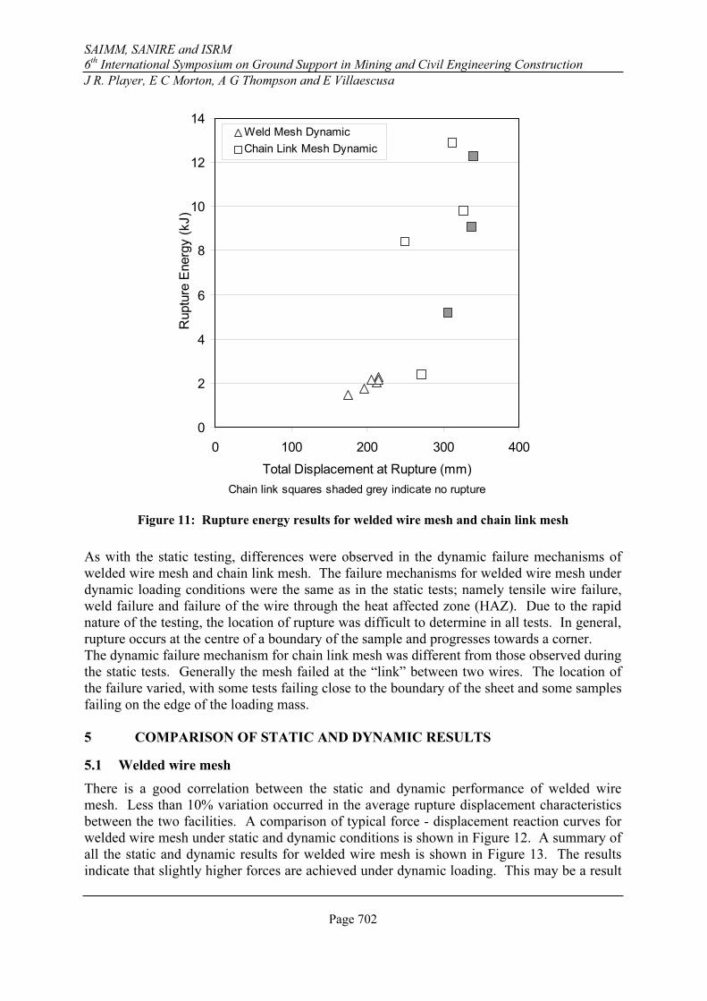
rupture energy for chain link mesh is 9kJ. The energy and displacement results are shown in
Figure 11.
SAIMM, SANIRE and ISRM
6th
International Symposium on Ground Support in Mining and Civil Engineering Construction
J R. Player, E C Morton, A G Thompson and E Villaescusa
Page 702
0
2
4
6
8
10
12
14
0 100 200 300 400
Total Displacement at Rupture (mm)
Rupture E
nergy (kJ)
Weld Mesh Dynamic
Chain Link Mesh Dynamic
Chain link squares shaded grey indicate no rupture
Figure 11: Rupture energy results for welded wire mesh and chain link mesh
As with the static testing, differences were observed in the dynamic failure mechanisms of
welded wire mesh and chain link mesh. The failure mechanisms for welded wire mesh under
dynamic loading conditions were the same as in the static tests; namely tensile wire failure,
weld failure and failure of the wire through the heat affected zone (HAZ). Due to the rapid
nature of the testing, the location of rupture was difficult to determine in all tests. In general,
rupture occurs at the centre of a boundary of the sample and progresses towards a corner.
The dynamic failure mechanism for chain link mesh was different from those observed during
the static tests. Generally the mesh failed at the “link” between two wires. The location of
the failure varied, with some tests failing close to the boundary of the sheet and some samples
failing on the edge of the loading mass.
5 COMPARISON OF STATIC AND DYNAMIC RESULTS
5.1 Welded wire mesh
There is a good correlation between the static and dynamic performance of welded wire
mesh. Less than 10% variation occurred in the average rupture displacement characteristics
between the two facilities. A comparison of typical force - displacement reaction curves for
welded wire mesh under static and dynamic conditions is shown in Figure 12. A summary of
all the static and dynamic results for welded wire mesh is shown in Figure 13. The results
indicate that slightly higher forces are achieved under dynamic loading. This may be a result

SAIMM, SANIRE and ISRM
6th
International Symposium on Ground Support in Mining and Civil Engineering Construction
J R. Player, E C Morton, A G Thompson and E Villaescusa
Page 703
of the larger loading area being used for dynamic testing which causes more wires to be
directly loaded.
0
10
20
30
40
50
60
70
0 50 100 150 200 250
Displacement (mm)
Fo
rce
(kN
)
Dynamic force - displacement result
Static force - dispalcement reuslt
Figure 12: Static and dynamic force – displacement response for welded wire mesh
0
10
20
30
40
50
60
70
0 50 100 150 200 250
Total Displacement at Rupture (mm)
Rupture F
orce (kN
)
Weld Mesh Dynamic
Weld Mesh Static
Figure 13: Comparison of static and dynamic force and displacement properties for welded
wire mesh

SAIMM, SANIRE and ISRM
6th
International Symposium on Ground Support in Mining and Civil Engineering Construction
J R. Player, E C Morton, A G Thompson and E Villaescusa
Page 704
5.2 Chain link mesh
The chain link mesh results did not have as good a correlation between the static and dynamic
performance as welded wire mesh. Figure 14 shows the typical static and dynamic force –
displacement responses of chain link mesh. The results indicate a difference in the stiffness
performance of the mesh between the two facilities. This effect may be a result of the
differing loading areas between the two facilities presents a summary of the force
displacement results from the two facilities. The results show that the static test facility has
more consistent force – displacement results but underestimates the maximum potential force.
This is likely to be due to the influence of the failure mechanism under static test conditions.
Further testing is required to improve the static test loading configuration.
0
50
100
150
200
250
300
0 100 200 300
Displacement (mm)
Fo
rce
(kN
)
Static force - displacement result
Dynamic force - displacement result
Figure 14: Static and dynamic force – displacement reaction curves for chain link mesh

SAIMM, SANIRE and ISRM
6th
International Symposium on Ground Support in Mining and Civil Engineering Construction
J R. Player, E C Morton, A G Thompson and E Villaescusa
Page 705
0
50
100
150
200
250
300
0 100 200 300 400
Total Displacement at Rupture (mm)
Rupture F
orce (kN
)
Chain Link Mesh Dynamic
Chain Link Static
Chain link squares shaded grey indicate no rupture
Figure 15: Comparison of static and dynamic force and displacement properties for chain link
mesh
6 CONCLUDING REMARKS
Static and dynamic testing using the WASM test method has provided good comparisons for
various mesh types. A comparison of static and dynamic test results has shown a good
correlation between the two facilities. High tensile 4mm diameter chain link mesh has much
higher force, displacement and energy capabilities than standard welded wire mesh currently
used in Western Australian mines.
7 REFERENCES
Ortlepp, W.D. 1983. Considerations in the design of support for deep hard rock tunnels. 5th
international congress on rock mechanics. Vol.2, Balkema Rotterdam pp. 179 - 187.
Pakalnis, V and D. Ames 1983. Load tests on mine screening. Underground support
systems. Canadian Institute of Mining Metallurgy and Petroleum, Special Volume 35. Udd, J
(ed) pp 79 – 83
Player, JR, Villaescusa, E & Thompson, AG 2004, 'Dynamic testing of rock reinforcement
using the momentum transfer concept', Proceedings of the Fifth International Symposium on
Ground Support, eds. E Villaescusa & E Potvin, Balkema, Perth, pp. 327-340.
Roth, A, Windsor C.R., Coxon J. and de Vries R. 2004. Performance assessment of high
tensile wire mesh ground support under seismic conditions. Ground support in mining and
underground construction. Villaescusa and Potvin (ed). pp. 589 - 594

SAIMM, SANIRE and ISRM
6th
International Symposium on Ground Support in Mining and Civil Engineering Construction
J R. Player, E C Morton, A G Thompson and E Villaescusa
Page 706
Tannant. D. 2001. Load capacity and stiffness of welded wire, chain-link and expanded metal
mesh. Section 3. International seminar on mine surface support liners: Membrane, shotcrete
and mesh. August,
Tannant, D, Kaiser, P.K, and Maloney S.1997. Load - displacement properties of welded -
wire, chain - link and expanded metal mesh. International symposium on rock support -
Applied solutions for underground structures. Lillehammer Norway. Broch, E Myrvang, A
Stjern, G (ed). June 22 - 25, pp. 651 - 659.
Thompson, AG 2001. Rock support action of quantified by testing and analysis. Section 1.
International seminar on mine surface support liners: Membranes, shotcrete and mesh, ACG:
Perth.
Thompson, AG, Windsor, CR and Cadby, GW 1999. Performance assessment of mesh for
ground control applications. Rock support and reinforcement practice in mining. Villaescusa,
Windsor, Thompson (ed). pp. 119-130.
Van Sint Jan, M and Cavieres P. 2004. Large scale static laboratory test of different support
systems. Ground support in mining and underground construction. Eds Villaescusa and
Potvin , 571-577, Balkema:Leiden.
Villaescusa, E 1999. Laboratory testing of weld mesh for rock support. Rock support and
reinforcement practice in mining. Villaescusa, E, Windsor, C and Thompson, A (ed).
Balkema Rotterdam pp. 155 - 159.
Villaescusa E, Player JR, Morton EC and Thompson AG 2008. Ground Support at the WA
School of Mines. MassMin 2008. June 9-11, Luleå, Sweden.. pp. In print.