statement of work · pdf filestatement of work for s-012 (24 ... electrical - lighting legend...
TRANSCRIPT

Statement of Work for S-012 (24 January 2013) Page 1
STATEMENT OF WORK
FOR S-012
(OFFICE)
GENERAL CONSTRUCTION SERVICES
For RENOVATION (MAKE READY) OF COMPOUND
HOUSING TO MEET INTERNATIONAL BUILDING AND SAFETY CODES.
U.S. CONSULATE Erbil, IRAQ
24 JANUARY 2013

Statement of Work for S-012 (24 January 2013) Page 2
TABLE OF CONTENTS
1.0 Project Description ............................................................................................................... 3
2.0 General Conditions ........................................................................................................... 4-5 3.0 Bid Form……………………………………………………...……………………………………….6
4.0 Scope of Work ................................................................................................................. .7-19
5.0 Project Schedule .......................................................................................................... 20-21
6.0 Responsibilities & Project Management ............................................................ 21-22
ATTACHMENTS
A. DRAWINGS
1. Existing - Site Plan
2. Existing - First Floor Plan
3. Existing - Second Floor Plan
4. Existing - Roof Plan
5. New - Site Plan
6. New - First Floor Plan
7. New - Second Floor Plan
8. New - Roof Plan
9. IT - Electrical - Lighting Legend
10. IT - Electrical - Lighting Plan - First Floor
11. IT - Electrical - Lighting Plan - Second Floor
12. IT - Electrical - Lighting Plan - Roof
13. Electrical Single Line Diagram
14. Electrical Panelboard Schedule

Statement of Work for S-012 (24 January 2013) Page 3
1.0 PROJECT DESCRIPTION
1. PROJECT SYNOPSIS
The project is described as “Renovation of Property Number: S-012 (Office) at the US
Consulate, Erbil, Iraq.
The Contractor should furnish all necessary materials, labor, transportation, equipments,
investigation and supervision, etc. Work will performed within in fixed-price contract.
2. BACKGROUND
At present the Office S-012 does not meet US life safety, comfort nor security standards. The
Office must be upgraded to address various things such as wiring, windows, plumbing,
electrical, mechanical and security concerns.
3. SOLUTION
Improve life safety conditions by replacing electrical internal -panelboards, and installing
Ground Fault Circuit (GFCI) breakers for all areas as required. Confirm, repair and/or
replace the ground in all electrical circuits within the building per NEC. Install additional
circuits as necessary. Upgrade office condition by installing a small kitchenette, bathroom
surfaces (including lowering of both bathroom floors), and fixtures. Upgrading the electrical
system by changing the internal panelboards with a molded case panel; make sure all the
power outlets and equipments are grounded. Put all the wires and cables in conduit and using
a NEMA water proof cover for all outdoor power outlets. Paint the exterior and interior.

Statement of Work for S-012 (24 January 2013) Page 4
2.0 GENERAL CONDITIONS
1. Fixed-Price Proposal. The Contractor shall provide one fixed-priced Proposal for the complete Project that includes every aspect of the Work.
2. Specifications. The Work shall be governed by the US Consulate, Erbil, Iraq. International Codes, which includes the National Fire Prevention Association (NFPA), International Building Code, International Mechanical Code, International Plumbing Code, and National Electric Code (NEC), also are applicable. Should there be a discrepancy between the US Consulate Specifications and the applicable Building Code, the more stringent of the two shall govern.
The Contractor is responsible for compliance with all Building Codes; Work not in compliance with the Codes shall be deemed to be unacceptable.
3. Execution. The Work shall be executed in a diligent and workmanlike manner in accordance with the negotiated fixed-price, this Scope of Work, the Project Schedule, International Building Codes, and the laws of the City of Erbil where applicable.
4. Work Hours. Unless otherwise agreed with COR or the Facility Manager, the Work
shall be executed during normal Embassy work hours. Night, weekend or holiday work shall not be permitted except as arranged in advance with Facilities Management and COR. Embassy holiday schedule is available from Facilities Management or COR.
5. Safety. The Contractor shall be responsible for conducting the work in a manner that
ensures the safety of residents, employees and visitors to the Embassy, and the Contractor’s employees.
6. Workforce. The contractor shall provide all supervision, skilled and unskilled labor
needed to perform the work. The contractor shall comply with embassy security policy by providing embassy approved escorts. Contractor provided escorts shall be in quantity sufficient to comply with RSO escort ratios for number of workers on the project. The contractor shall prepare requests to RSO for vetting of employees to get escort badges. The Contractor or government may request for workers to be badged for unescorted Embassy access by going through RSO vetting process.
7. Subcontractors. Contractor shall be responsible for the conduct and workmanship of
Subcontractors engaged in the Project, and for Subcontractors compliance with the terms of this Statement of Work. The Contractor is responsible for the behavior and workmanship of Subcontractors while on Consulate property.
8. Modification to Contract. The Contractor shall not incur any costs beyond those
described in this SOW unless directed otherwise in writing by the Contracting Officer. Any work performed by the Contractor beyond this SOW without written direction from the Contracting Officer will be at the Contractor’s own risk and at no cost to the Consulate.

Statement of Work for S-012 (24 January 2013) Page 5
9. Stop Work. At any time during the Project, the Contracting Officer reserves the right to Stop Work for protection of employees or visitors, security, or any other reason at his/her discretion.
10. Submittals. The contractor is responsible to submit shop drawings prior to fabrication and release of any materials for the Facility Manager and COR Review and approval. The Facility Manager review, however, does not relieve of the contractor’s responsibility for the engineering work as to provide a complete working system.
11. Excavation and Utilities. The contractor is responsible to locate all existing utility
lines prior to any excavation. Prior to disconnecting any existing utility services, the contractor is responsible to provide 48-hour advance notice to the COR.
12. Close-out. Prior to final acceptance, the contractor is to submit to the COR marked up
drawings (As-Built) reflecting the work as constructed. The drawings shall be digitally submitted on a CD-ROM in both AutoCAD and PDF format.
13. Housekeeping. The contractor is responsible to clean up daily after working hours.

Statement of Work for S-012 (24 January 2013) Page 6
3.0 BID FORM Construction Cost Breakdown: S-012-Office, Erbil, Iraq
Building Number; S-012
US CONSULATE ERBIL
No Descriptions Unit Qty Unit Price $
Total Price $
1 Administration A Mobilization / Demobilization LS 1
B Submittals – product data & shop drawings
LS 1
Administration Sub-Total 2 Construction Work A Architectural LS 1 B Mechanical-Plumbing LS 1 C Electrical LS 1 D Voice and Data Cabling LS 1 E Close-out LS 1 Construction Sub-Total 3 DBA Insurance
A
Contractor shall cover each of its workers at the site with DBA Workers’ Compensation coverage, and require its subcontractors to do the same. Contractor must furnish certificate evidencing this coverage to Engineer prior to starting work.
LS 1
DBA Insurance Sub-Total Items 1 thru 3 Sub-Total G & A Sub-Total Profit
4 Basic Bid - Contract Cost
A Bid - Contract Cost

Statement of Work for S-012 (24 January 2013) Page 7
4.0 SCOPE OF WORK:
Renovation of Property Number: S-028 (Office) “Make Ready” the contractor shall be providing all materials, tools and equipments, labors, transportation, and supervision.
1. General Requirements
a. Within 5 days of Notice to Proceed, the contractor shall provide to the COR a project schedule showing start to completion including significant milestones.
b. Within 10 days of Notice to Proceed “NTP”, the Contractor shall provide to the COR
details of the proposed installation utilizing written description or sketches or both.
c. The contractor is responsible to dispose of the construction debris outside of the Consulate Compound. Include, but not limited to soils, rock excavation, packing materials and scrap steel.
d. The contractor is responsible to properly layout and prepare for the renovation
based on locations provided by FAC.
e. When pursuing the work, the contractor is to take extra care as not to damage existing structure.
f. All construction work will be in conformance with the following Codes:
f1) International Building Code, 2009 Edition plus the 2011 OBO International
Code
Supplement.
f2) International Plumbing Code, 2009 Edition plus the 2011 OBO International
Code Supplement.
f3) International Mechanical Code, 2009 Edition plus the 2011 OBO
International Code Supplement.
f4) International Fire Code, 2009 Edition plus the 2011 OBO International Code
Supplement.
f5) National Electric Code, 2011 Edition plus the 2011 OBO International Code
Supplement.
F6) International Residential Code 2009 Edition plus the 2011 OBO International
Code Supplement.
F7) National Fire Protection Association, NFPA 101 & NFPA 58
F8) ICC/ANSI A117.1-98 Accessible and Usable Buildings and Facilities
F9) NECA 90 Recommended Practice for Commissioning Building Electrical
Systems (ANSI)
F10) NECA 1-2010 Standard Practice of Good Workmanship in Electrical
Construction (ANSI)
F11) IEEE C2-2012 National Electrical Safety Code (NESC)

Statement of Work for S-012 (24 January 2013) Page 8
A. ARCHITECTURAL
The contractor and his structural engineer are required to investigate each new opening, stairway
support point, and equipment location for adequate structural support and ensure that their proposed
work does not compromise the structural integrity of the building. The engineer should sketch or
report the methods towards resolution before the work is done. The contractor’s structural engineer
should also investigate stairway construction and floor loading where residential space is being
converted to office space.
General Notes for the Building:
1. Floors
a. Clean and polish all floors (interior and exterior) to original condition. Remove all
plaster and other materials. Level interior floors as needed.
b. Add new tile/s for areas shown on the drawings. Tiles shall have non-slip surface.
Provide sample for COR approval.
2. Windows
a. Provide and install all new UPVC watertight windows with integral reinforcement
stiffeners. Provide sample for COR approval.
i. Includes all required hardware.
ii. Casement window (Inside opening - swing inward)
iii. Minimum clear opening dimensions of each pane:
12” (300mm) wide
24” (600mm) tall.
iv. Glass:
Insulated double glazing
Tempered glass
Tint (bronze) all windows to reduce sunlight.
v. UPVC Color: Brown.
b. Provide and install new vertical blinds for all windows. Provide sample of similar
Blinds for approval. Currently there are no blinds on the windows.
3. Doors
a. Exterior Doors:
i. Provide and install all new wooden doors and frames, solid core door shall be
4cm thick. Provide sample for COR approval
ii. Doors shall be similar to other installed doors/frames on site.
iii. Contractor to dispose of exiting doors and frames.
iv. Provide and Install one cylinder deadbolt lock, door handles and sliding
deadbolt lock. Provide sample for COR and RSO/ARSO approval.
b. Interior Doors:
i. Remove and discard existing doors and frames.
ii. Provide and install solid core doors and frames for all rooms with all required
hardware.
iii. Color: Light Brown (flat). Provide sample for COR approval.

Statement of Work for S-012 (24 January 2013) Page 9
4. Patching and Painting
a. Patching and Painting shall be required for the following surfaces:
i. All interior walls. Color: Beige (flat)
ii. All interior ceilings. Color: White (flat).
iii. All exterior walls. Color: Shall be determined by COR.
iv. All exterior window
including Grills where
necessary. Color: Shall be determined by COR.
v. Perimeter wall. Color: Shall be determined by COR.
vi. Exterior Steel Stairs Color: Shall be determined by COR.
vii. Exterior Steel
Balcony Rails: Color: Shall be determined by COR.
viii. Exterior roof
Perimeter wall Color: Same as exterior walls.
b. Surface preparation:
i. Repair and finish all interior and exterior walls prior to painting-filling cracks,
removing nails, etc. from the walls.
ii. All wall penetration shall be sealed with waterproof sealant.
iii. Prior to painting and patching pressure wash exterior of building and the
perimeter walls.
iv. Sandblast or wirebrush exterior steel stairs. Remove all rust.
c. Paint coatings shall be as follows for all surfaces:
i. One (1) primer coat
ii. Two (2) finish coats
d. Paint Specification:
i. Hi quality paint is required.
ii. Epoxy paint shall be used for all bathrooms.
5. Bathrooms
a. Provide and Install in all bathrooms the following new furnishings and fixtures:
i. Sink. Provide sample for COR approval.
ii. Toilet (all Western style). Provide sample for COR approval.
iii. Urinal (male bathroom only).
iv. Stall Partitions
v. The following bathroom fixtures: Provide sample for COR approval.
1. Mirror above sink with the soap and tooth brush holder
2. Towel bars (for sink)
3. Toilet paper holder
4. Coat Hanger (2 required – on back of doors)
b. Provide and install in all bathrooms a 25cm exhaust fan with louvers in the wall with
switch located next to the light switch. Cut wall for installation.
c. Install stainless steel drain cover with vapor barrier “goose neck” designs for all floor
drains
6. Kitchen
a. Provide and install the following new furnishing:
i. Kitchen cabinets. Design and sample shall be determined by COR.
ii. Kitchen sink. Provide sample for approval.
Statement of Work for S-012 (24 January 2013) Page 10
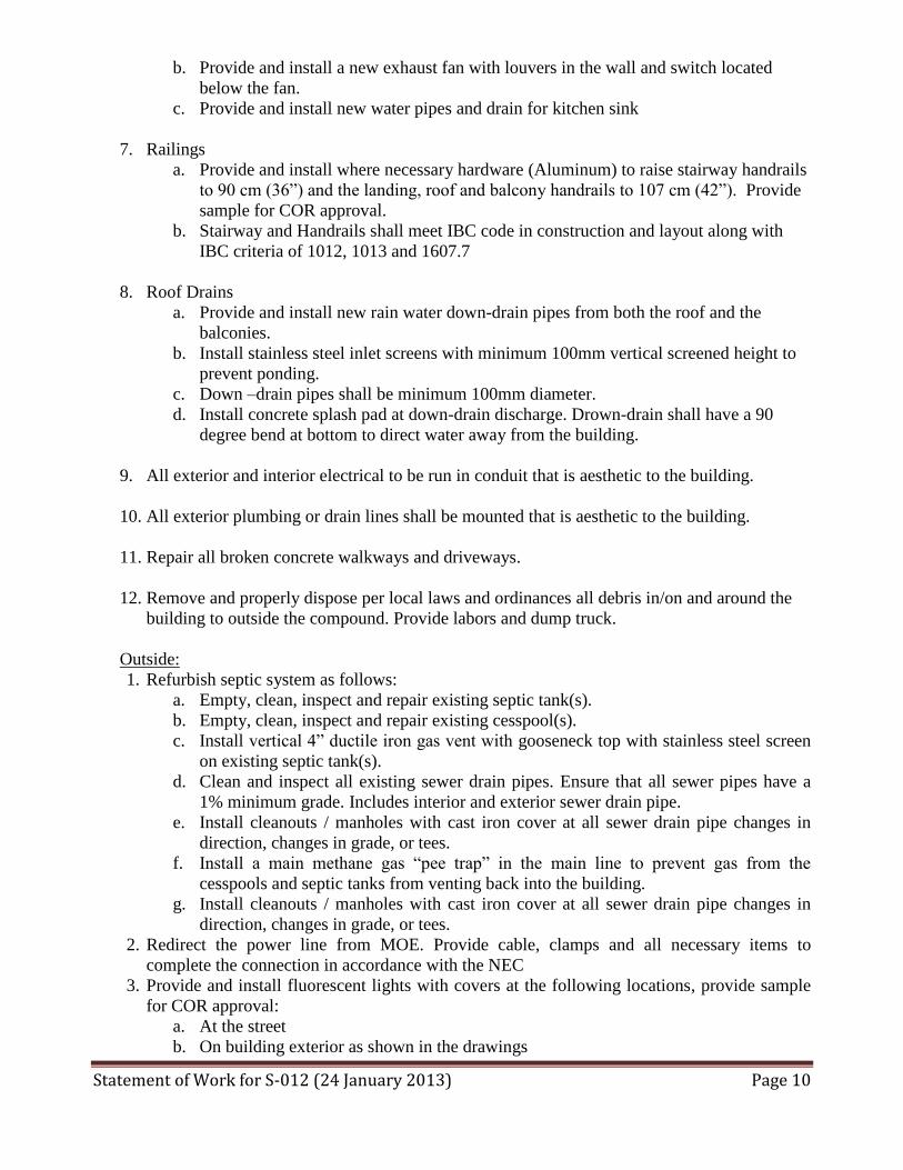
b. Provide and install a new exhaust fan with louvers in the wall and switch located
below the fan.
c. Provide and install new water pipes and drain for kitchen sink
7. Railings
a. Provide and install where necessary hardware (Aluminum) to raise stairway handrails
to 90 cm (36”) and the landing, roof and balcony handrails to 107 cm (42”). Provide
sample for COR approval.
b. Stairway and Handrails shall meet IBC code in construction and layout along with
IBC criteria of 1012, 1013 and 1607.7
8. Roof Drains
a. Provide and install new rain water down-drain pipes from both the roof and the
balconies.
b. Install stainless steel inlet screens with minimum 100mm vertical screened height to
prevent ponding.
c. Down –drain pipes shall be minimum 100mm diameter.
d. Install concrete splash pad at down-drain discharge. Drown-drain shall have a 90
degree bend at bottom to direct water away from the building.
9. All exterior and interior electrical to be run in conduit that is aesthetic to the building.
10. All exterior plumbing or drain lines shall be mounted that is aesthetic to the building.
11. Repair all broken concrete walkways and driveways.
12. Remove and properly dispose per local laws and ordinances all debris in/on and around the
building to outside the compound. Provide labors and dump truck.
Outside:
1. Refurbish septic system as follows:
a. Empty, clean, inspect and repair existing septic tank(s).
b. Empty, clean, inspect and repair existing cesspool(s).
c. Install vertical 4” ductile iron gas vent with gooseneck top with stainless steel screen
on existing septic tank(s).
d. Clean and inspect all existing sewer drain pipes. Ensure that all sewer pipes have a
1% minimum grade. Includes interior and exterior sewer drain pipe.
e. Install cleanouts / manholes with cast iron cover at all sewer drain pipe changes in
direction, changes in grade, or tees.
f. Install a main methane gas “pee trap” in the main line to prevent gas from the
cesspools and septic tanks from venting back into the building.
g. Install cleanouts / manholes with cast iron cover at all sewer drain pipe changes in
direction, changes in grade, or tees.
2. Redirect the power line from MOE. Provide cable, clamps and all necessary items to
complete the connection in accordance with the NEC
3. Provide and install fluorescent lights with covers at the following locations, provide sample
for COR approval:
a. At the street
b. On building exterior as shown in the drawings

Statement of Work for S-012 (24 January 2013) Page 11
4. Perimeter Wall Along Street
a. Reduce the height of perimeter wall along the street leaving 40 cm from ground level.
b. Patch top and sides of block wall for smooth surface and paint to match existing wall.
c. Leave columns at the entrance(s).
5. Remove and replace front tiles.
6. Remove and replace existing sidewalk at house front. New sidewalk to be tiled.
7. Remove existing water pump enclosure. Install new pump with check valve and integrate
with level switch at roof tanks.
8. General landscaping (trimming and grass cutting) and removal of excess vegetation.
Conference Room A101
1. Provide and install exterior wooden solid core door 4cm thick. Provide sample for COR
approval.
2. Remove existing wooden partition wall.
3. Replace existing three (3) windows at entrance with one (1) window.
Hallway A106
4. Provide and install exterior wooden solid core door 4cm thick. Provide sample for COR
approval.
5. Remove wooden cabinets over bathroom and close opening. Patch and paint.
6. Abandon Bathroom under stairs
a. Remove floor toilet, plug and abandon
b. Remove door and all bathroom fittings.
c. Clean, Path and paint for use as storage.
Kitchen A104
1. Provide and Install required kitchen furnishings
a. Sink
b. Exhaust fan.
c. Kitchen Cabinets. Sample and design will determine during the site visit.
2. Remove overhead wooden cabinets (do not replace)
3. Grade out 3cm step at door and slope to bathroom at 1:50.
4. Install new PVC exterior door.
5. Re-circuit all countertop power outlets into a new GFCI circuit and circuit breaker
Bathrooms A105
1. Door:
a. Remove and discard existing door and frame.
b. Raise door lintel to 1.9 m vertical clearance and increase width to 1.2m
c. Provide and install new brown PVC bathroom door and frame
d. Provide and install “Female” door sign
2. Remove existing bathtub.
3. Remove and replace all drains and plumbing as required.
4. Provide and install new bathroom furnishings and fixtures.
5. Provide and install one (1) new sink.
6. Provide and install two (2) new toilets.
7. Provide and install new sliding doors and stall partitions.
8. Remove and replace bathroom wall tiles and floor tiles (non-slip)
9. Re-circuit all power outlets into a new GFCI circuit and circuit breaker

Statement of Work for S-012 (24 January 2013) Page 12
Stairway A106/A206
1. Remove and replace existing handrails.
2. Provide and install stairway handrail to 107cm height (Aluminum type. Provide sample for
COR approval).
3. Remove and replace floor tiles on stairs and landing.
4. Provide and install new door for storage area under stairs.
5. Plug and abandon existing toilet under stairs. Remove and dispose of all existing plumbing.
Balcony 207
1. Remove balcony hand rails and replace with aluminum handrails. 2. Install new PVC exterior door.
Balcony 208
1. Existing steel stairs to roof:
a. Stairway handrail to be extended to 107cm height
b. Clean and paint
2. Install new PVC exterior door.
Hallway 206
1. For wall at bathroom, remove wall tiles and resurface (patch and paint)
Bathrooms A205
10. Door:
a. Remove and discard existing door and frame.
b. Raise door lintel to 1.9 m vertical clearance and increase width to 1.2m
c. Provide and install new brown PVC bathroom door and frame
d. Provide and install “Male” door sign
11. Remove and replace all drains and plumbing as required.
12. Provide and install new bathroom furnishings and fixtures.
13. Provide and install one (1) new sink.
14. Provide and install one (1) new toilet and one (1) new urinal.
15. Provide and install new sliding doors and stall partitions.
16. Remove and replace bathroom wall tiles and floor tiles (non-slip)
17. Re-circuit all power outlets into a new GFCI circuit and circuit breaker
Roof C201
1. Replace all roof panel mastic.
2. Provide and install balcony wall railing on top of existing perimeter wall to 90cm height
(Aluminum type. Provide sample for COR approval).
3. Clean all debris from roof.
4. Replaster, patch and paint roof perimeter wall.
Statement of Work for S-012 (24 January 2013) Page 13
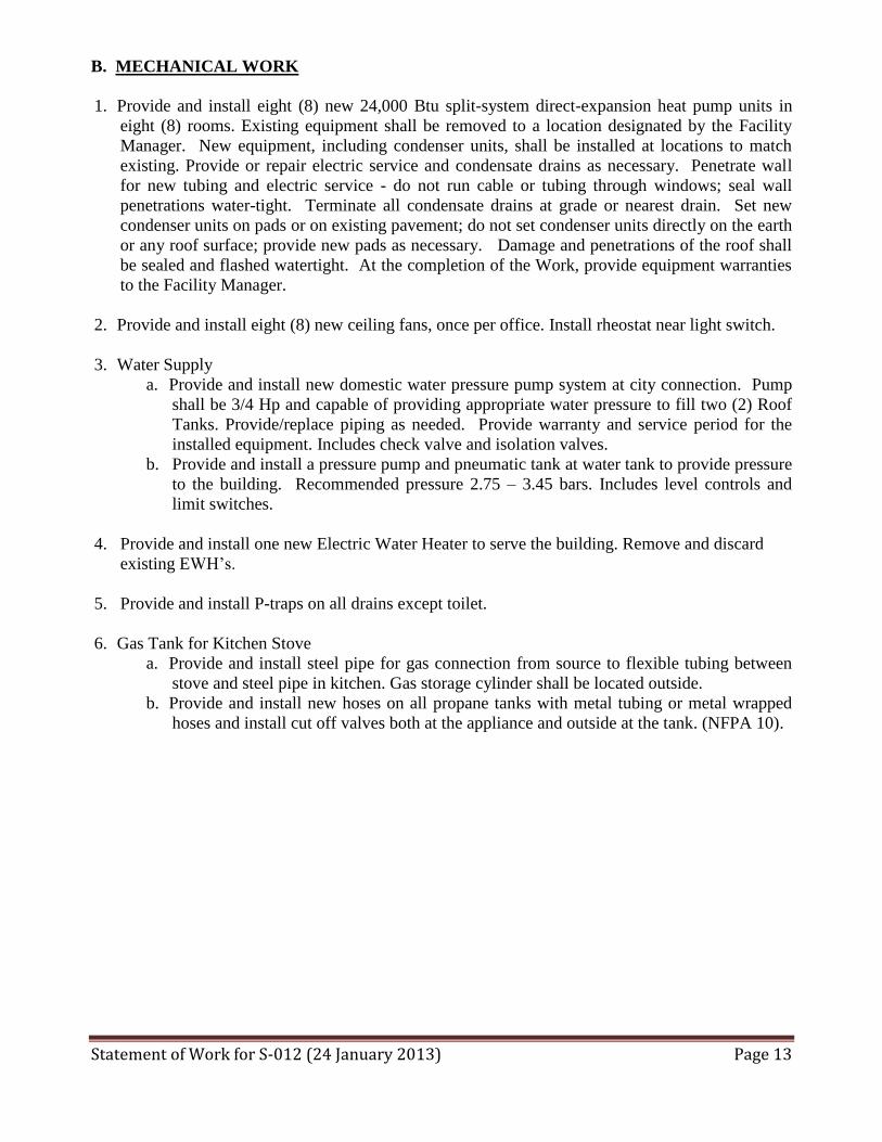
B. MECHANICAL WORK
1. Provide and install eight (8) new 24,000 Btu split-system direct-expansion heat pump units in
eight (8) rooms. Existing equipment shall be removed to a location designated by the Facility
Manager. New equipment, including condenser units, shall be installed at locations to match
existing. Provide or repair electric service and condensate drains as necessary. Penetrate wall
for new tubing and electric service - do not run cable or tubing through windows; seal wall
penetrations water-tight. Terminate all condensate drains at grade or nearest drain. Set new
condenser units on pads or on existing pavement; do not set condenser units directly on the earth
or any roof surface; provide new pads as necessary. Damage and penetrations of the roof shall
be sealed and flashed watertight. At the completion of the Work, provide equipment warranties
to the Facility Manager.
2. Provide and install eight (8) new ceiling fans, once per office. Install rheostat near light switch.
3. Water Supply
a. Provide and install new domestic water pressure pump system at city connection. Pump
shall be 3/4 Hp and capable of providing appropriate water pressure to fill two (2) Roof
Tanks. Provide/replace piping as needed. Provide warranty and service period for the
installed equipment. Includes check valve and isolation valves.
b. Provide and install a pressure pump and pneumatic tank at water tank to provide pressure
to the building. Recommended pressure 2.75 – 3.45 bars. Includes level controls and
limit switches.
4. Provide and install one new Electric Water Heater to serve the building. Remove and discard
existing EWH’s.
5. Provide and install P-traps on all drains except toilet.
6. Gas Tank for Kitchen Stove
a. Provide and install steel pipe for gas connection from source to flexible tubing between
stove and steel pipe in kitchen. Gas storage cylinder shall be located outside.
b. Provide and install new hoses on all propane tanks with metal tubing or metal wrapped
hoses and install cut off valves both at the appliance and outside at the tank. (NFPA 10).

Statement of Work for S-012 (24 January 2013) Page 14
C: STRUCTURAL WORK:
General
Modifications to either the existing superstructure or the applied loads, the addition of new
structures, and restoration or rehabilitation of site structures shall be evaluated by a Structural
Engineer.
The type of work requiring evaluation includes, but is not limited to:
Modification of floors, roofs, walls, beams, and other load-bearing elements
Installation of new equipment (e.g. safes, water tanks, HVAC equipment)
Change of use or occupancy (e.g. residential to office)
Installation of stairways
Any other items which may be of interest to the Structural Engineer
Qualifications
The Structural Engineer must:
Be a licensed professional in accordance with the 2011 Building Code of Overseas Building
Operations, Chapter 1.
Be a Professional Engineer with Structural specialty
Have prior experience with the structure type, local construction practices, and local materials
used in the building being evaluated.
Have the capacity to prepare or deliver documentation in the English language.
Where indigenous expertise is employed in execution of the work, the indigenous personnel shall:
Be registered and/or licensed as a structural engineer in the local jurisdiction.
Have prior experience with the types of buildings, local construction practices, and local
materials.
Have the capacity to prepare or deliver documents in the English language.
Be under the direct supervision of the Structural Engineer

Statement of Work for S-012 (24 January 2013) Page 15
D. ELECTRICAL WORK
1. Provide and install a new Main Circuit Breaker Panel rated 250A, 230/400V (3-Phase 4-wire plus
ground) with a main circuit breaker and 24 single pole circuit breaker positions. See the Panel
Board Schedule for circuit breaker sizes. Panel Board ampere interrupting capacity (AIC) rating
shall be greater than the ampere short circuit available from the utility company at the
panel. Provide and locate the SPD at or inside the panel in accordance with OBO specification
16289 Surge Protection Devices.
2. Establish a ground from panel to two ground rods (the ground rods must meet local codes) 3
meters long and spaced not less than 1.8M apart). Connect 35mm sq copper wires to each ground
rod and the city water pipe to the main circuit breaker Panel. Impedance of ground path for any
electrodes may not exceed 25 ohms. (NEC 250.56)
3. Connect service from MOE grid to new service panel.
4. Exhaust fans to be on separate switch at door next to light switch.
5. All circuits inside the house shall be in EMT conduit or similar.
6. GFCI Receptacles Shall not be used. Outlets designated GFCI protection shall be fed from a
GFCI circuit breaker. One GFCI breaker, rated for 10mA or less ground fault trip. 50Hz, 240V
(line to ground) shall be installed in an enclosure adjacent to the first receptacles in the branch
circuit. The breaker will provide ground fault protection for all receptacles in the circuit.
Receptacle circuits in all wet areas are to be protected by the GFCI circuit breakers (kitchen,
bathroom, outdoors).
7. Provide and install weatherproof energy-efficient outdoor lights where existing lights are
presently installed.
8. Remove and dispose of existing lighting fixtures.
8. Remove and dispose all unused wires, cables and panels. Repair any damage caused by
Work performed. Clean all work areas.
9. Provide and install new copper wiring throughout the building. The wiring to be THHN/THWN
insulated, 600Volts rated equal to NEC #12 (4 mm square). Remove and dispose of all replaced
wiring.
10. Conduits and Protection: All wiring and cabling shall be installed in metal conduit or Raceway.
11. Provide and install an electrical outlet along all Interior walls 3 meters apart in each room.
12. Provide and install AC weatherproof outlets on exterior walls near the outdoor condenser units.

Statement of Work for S-012 (24 January 2013) Page 16
13. Provide and install new ceiling fans with Rheostat switches near light switch in all living rooms,
dining rooms, bedrooms, and kitchens.
14. Provide and install new Fluorescent lighting fixtures (square down light types) with covers on
each Interior wall with switches located at the entrances of all rooms. Remove and dispose
of all Existing lighting fixtures.
15. At the first landing between the two stairways and at the top landing provide and install
fluorescent lights with cover. Provide and install a 2-way switch at the bottom floor and the top
floor of the stairway.
16. Provide and install one (1) outdoor weatherproof electrical receptacle on the wall at the service
entrance to the building.
17. Provide and install one (1) outdoor weatherproof electrical receptacle on the wall of each
balcony.
18. Provide and install electrical outlet in Bathrooms to include one for the newly installed exhaust
fan. Exhaust fan to be on separate switch at door next to light switch.
19. Provide and install energy-efficient outdoor lights at each exterior entrance and balcony with
switches on interior side of door way.
20. Provide and install new electrical receptacle at the roof top water tank for the new water
pressure pump.
21. The contractor will provide a written report/form verifying that each receptacle has been
inspected and passes a Ohmmeter AC ground fault loop impedance test along with a ground
connection test.
22. All receptacles shall be 2-pole, 3-wire ground type. They must be local type or NEMA type
receptacles.
23. Local standard receptacles may be rated 240v, 13A or 16A.

Statement of Work for S-012 (24 January 2013) Page 17
E. Installation of Voice and Data Cable Network (See Attachment at end)
F. Closeout 1. At completion of work, the Contractor shall clean any impacted areas to a condition equal to
original condition.
2. All shipping materials and construction debris are to be disposed of in a legal manner outside of
the Compound.
3. Prior to Final Acceptance the Contractor shall submit to the Contracting Officer Representative
marked up drawings (As-Built) reflect the work as constructed. The drawings shall be digitally
submitted on a CD-ROM in both AutoCAD and PDF format.
SAFETY (FAR 52.236-13 Accident Prevention.)
1. The Contractor shall provide and maintain work environments and procedures which
will:
(a) Safeguard the public and Government personnel, property, materials, supplies, and
equipment exposed to Contractor operations and activities.
(b) Avoid interruptions of Government operations and delays in project completion dates.
(c) Control costs in the performance of this contract.
2. For these purposes on contracts for construction or dismantling, demolition, or removal of
improvements, the Contractor shall-
(a) Provide appropriate safety barricades, signs, and signal lights
(b) Comply with the standards issued by the Secretary of Labor at 29 CFR part 1926 and 29 CFR
part 1910
(c) Ensure that any additional measures the Contracting Officer determines to be reasonably
necessary for the purposes are taken.
3. Contractor shall comply with all pertinent provisions of the latest version of U.S. Army Corps of
Engineers Safety and Health Requirements Manual, EM 385-1-1, in effect on the date of the
solicitation.
4. Whenever the Contracting Officer becomes aware of any noncompliance with these
requirements or any condition which poses a serious or imminent danger to the health or safety
of the public or Government personnel, the Contracting Officer shall notify the Contractor orally,
with written confirmation, and request immediate initiation of corrective action.
This notice, when delivered to the Contractor or the Contractor's representative at the work site,
shall be deemed sufficient notice of the noncompliance and that corrective action is required.
After receiving the notice, the Contractor shall immediately take corrective action.
If the Contractor fails or refuses to promptly take corrective action, the Contracting Officer may
issue an order stopping all or part of the work until satisfactory corrective action has been taken.

Statement of Work for S-012 (24 January 2013) Page 18
The Contractor shall not be entitled to any equitable adjustment of the contract price or extension
of the performance schedule on any stop work order issued under this clause.
5. The Contractor shall insert this clause, including this paragraph (e), with appropriate changes in
the designation of the parties, in subcontracts
5.0 PROJECT SCHEDULE
1. Approximate dates of pre-award activities Pre-Bid Site Survey o/a Bids Due o/a Contract Award o/a Notice to Proceed (NTP) o/a
2. Construction Milestones, from Notice to Proceed
Notice to Proceed (NTP) 0 Days from NTP Project Schedule to OBO 5 Project Design Notes / Sketches 4 FAC Review 20 Procurement, Shipping 25 Fabrication 35 Construction Completion 40 Project Acceptance 45
3. Deliverables Construction Schedule 2 Days from NTP Project Design Notes / Sketches 4 Submittals for Major Equipment 5 Manufacturer’s Literature 45 As-Built, Warranties 45
4. Commencement, Prosecution, and Completion of Work The Contractor shall be required to (a) commence work under this contract within five (5) calendar days after the date the Contractor receives the Notice to Proceed, (b) prosecute the work diligently, and (c) complete the entire work ready for use not later than sixty (60) calendar days after NTP. The time stated for completion shall include final cleanup of the premises.

Statement of Work for S-012 (24 January 2013) Page 19
6.0 RESPONSIBILITIES AND PROJECT MANAGEMENT
1. COR. A Contracting Officers Representative (COR) will be assigned to ensure quality assurance goals are met. The Contractor shall provide the COR access to the site at all times.
2. Point of Contact. The COR shall be the main point of contact for this Project. The
Contractor shall report to the COR on (a) status of the Project, (b) changes in Schedule, (c) accidents and safety issues, (d) disruptions to elevator or utility services; and all other important information pertaining to the Project
3. English Speaking Representative. The Contractor shall provide an English-speaking
representative on-site during all working hours with the authority to make all decisions on behalf of the Contractor and subcontractors.
4. Management Personnel. The Contractor shall staff the site, full-time, with a
competent senior manager who shall perform project management. Remote project management is not an option. This individual shall keep a detailed photographic and written history of the project and shall update the Government weekly.
5. Site Security. The Contractor is responsible for on-site security as necessary to ensure
no unauthorized access to their work sites. The Contractor is 100% responsible for securing their working materials and equipment. Any damage to facilities or infrastructure, which happens due to a lack of security, will be the responsibility of the Contractor to correct.
6. Contractor’s Temporary Work Center. The Contractor will be permitted to use a
designated area within the contract limits for operation of his construction equipment and office if warranted. If directed by the Contracting Officer, the Contractor shall not receive additional compensation to relocate his operations. The Contractor is responsible for obtaining any required additional mobilization area above that designated. On completion of the contract, all facilities shall be removed from the mobilization area within 5 days of final acceptance by the Contractor and shall be disposed of in accordance with applicable host government laws and regulations. The site shall be cleared of construction debris and other materials and the area restored to its final grade. The Contractor is responsible for maintaining this area in a clear orderly manner.
7. Health and Safety. The Contractor shall be solely responsible for risk assessments,
managing health, and safety issues associated with this project. The Contractor must provide cold water to all workers at the job sites. Based on hazard assessments, Contractors shall provide or afford each affected employee personal protective equipment (PPE) that will protect the employee from hazards. At a minimum PPE shall consist of eye protection, hard hats, and closed toe shoes. If the workers arrive on-site with sandals or athletic shoes, the Contractor is expected to provide rubber boots to them or send them home. All construction workers and management personnel must wear hard hats at all times on the construction sites. Contractor provided rubber boots

Statement of Work for S-012 (24 January 2013) Page 20
and rubber gloves shall be worn when working around concrete placement. Other PPE such as gloves, dust masks, air respirators (sewage work) are also recommended. These items must be provided at the Contractor’s expense. Workers may use discretion if they feel unsafe in using the equipment in a hostile environment. Any worker at an elevated location above 4 meters, with the exception of a portable ladder, must be provided and utilize a safety harness.
8. Progress Payments. If the contract awarder expects to receive more than one (1)
progress payment, the Contractor must submit a broken out Cost Proposal with a Schedule of Values in order to properly calculate the percentage of contract completion.

Statement of Work for S-012 (24 January 2013) Page 21
ATTACHMENT FOR 4.E Installation of Voice and Data Cable Network
Telecommunications Cabling System for
a Non-CAA Office Building
February 28, 2006
TELECOMMUNICATIONS CABLING SYSTEM FOR A NON-CAA OFFICE BUILDING

Statement of Work for S-012 (24 January 2013) Page 22
1.0General
Note: Use this document for office buildings that do not contain areas where classified processing is done, such as USAID buildings, office annex buildings, etc. Do not use this document for chancery buildings that contain classified areas.
The information in this document complies with the primary referenced standards listed in Subsection 1.6 below and any later variations or modifications to these documents. The cabling system as defined provides for a diverse Information Technology (IT) requirement spread throughout the building among multiple users. This cabling system should have maximum flexibility and adaptability to satisfy many different uses and applications conveying electronic information, telecommunications, entering into and sent within the building. This includes, but is not limited to, the following: telephone, unclassified data, fire, security, building management systems (BMS), television, wireless communications, and spare. This system provides the media infrastructure necessary to support modern telecommunications and IT systems. Application of these guidelines will enable in-service moves, additions, and changes to be accomplished easily and on a functional in-service basis.
1.1 System Level Cabling. Diplomatic buildings have a variety of different types of equipment that require power and interconnecting communications and control cabling. The level of importance of the equipment as well as the security requirements associated with the equipment will determine its required power redundancy and type of interconnecting cabling as well as its associated raceways and cable routing. The physical location of the equipment may also influence the type of raceways required for its associated cabling. This section provides the guidelines for the management of system level cabling for signal and control wiring in a New Office Annex (NOX). The goal is a certified, structured, integrated, shared media system, to the extent allowed by security and life safety codes. Integral to this system will be a vertical chase and several strategically placed equipment rooms and TRs. These are to house cross connects and interface to the various telecommunications systems. They will also contain support, control switching and patching equipment for information management (data) support equipment, security, alarms, video, audio, distribution, and other communications equipment
1.2 Design. The information provided in this design guideline reflects the types of information technology and the telecommunications that are in use at the Department of State (DOS). It is not the intent of these criteria to restrict the design of the contractor. The contractor is encouraged to present alternative proposals. If an alternative design proposal is believed to significantly improve the performance characteristics, the contractor shall provide a life cycle cost benefit analysis to OBO to support the alternative proposal. The contractor shall design a DOS structured cabling system that adheres to the ANSI/TIA/EIA standards, the Standard Embassy Design for New Annex Buildings, and this design manual. The structured cabling system shall be designed to support a minimum of eight (8) independent networks using common building pathways. The design shall combine the use of fiber optics and copper UTP cables, with a basic capability to support a bandwidth of up to 1.0 Gbps between any work area, telecommunications room, and 10Gbps for the data backbone. It shall use a Hierarchical Star topology, distributing services from telecommunication rooms using network switches for unclassified data networks, providing for the receipt and distribution of television signals, , and providing for future expansion capability for all network systems. The primary media is a combination of fiber optics, copper UTP and coaxial cables and shall be identified in the communications specifications part of the contract. The fiber optic (FO), coaxial, and copper UTP (referred throughout this document as Category X or CAT X) cable shall be approved by current ANSI/TIA/EIA standards unless stated otherwise. A primary consideration is to provide maximum flexibility for future requirements.

Statement of Work for S-012 (24 January 2013) Page 23
1.3 Future Expansion. The designer shall consider two future expansion issues: rapid increase of bandwidth requirements and increase in personnel. To prepare for increase in the bandwidth requirements, fiber optic cables will be terminated at each work station in addition to CAT X UTP copper cable. A description of systems available in the work areas is discussed later. Also, the backbone cabling shall be designed for 50% future expansion for pathways, termination devices, and switch ports while the horizontal cabling scheme shall be designed for 25% future expansion for pathways, and switch ports.
1.4 Contractor Qualifications.
1.4.1 Designers. The telecommunications firm to design a telecommunications cabling system for U.S. diplomatic facilities for OBO shall have 15 years experience designing cabling systems in accordance with (IAW) ANSI/TIA/EIA standards as listed in section 15. The firm shall provide an individual who has a bachelor’s degree in engineering/architecture or is a licensed, professional engineer (PE), and is a registered communications distribution designer (RCDD) with at least five years experience designing cabling systems in accordance with ANSI/TIA/EIA standards as listed in section 1.5.
1.4.2 Installers/Testers. The installation contractor shall be a U.S. firm regularly engaged in installing, terminating and testing of CAT X UTP with minimum bandwidth of 250 megahertz, and fiber optic cabling systems for the past five years. Experience shall be specific to installations in commercial office building and institutional type projects. The contractor shall have field supervisory personnel with experience equivalent to a Building Industry Consulting Service International (BICSI) certified technician level. Cabling shall be terminated and tested by field personnel with experience equivalent to BICSI installer level. The contractor’s field personnel should be knowledgeable of and have experience with ANSI/TIA/EIA standards as listed in section 1.6 below.
1.5 APPLICABLE CODES AND STANDARDS
NFPA 70 National Electrical Code (Latest Edition) (NEC)
ANSI/TIA/EIA Standard 310-D Cabinets, Racks, Panels, and Associated Equipment
ANSI/TIA/EIA Standard 526-7 Measurement of Optical Power Loss of Installed Singlemode Fiber Cable
Plant -- OFSTP-7
ANSI/TIA/EIA Standard 526-14A Optical Power Loss Measurement of Installed Multimode Fiber Cable Plant – OFSTP-14
ANSI/TIA/EIA Standard 568-B.1 Commercial Building Telecommunications
Cabling Standards Part 1: General Requirements and all addenda (Feb 2003)
ANSI/TIA/EIA Standard 568-B.2 Commercial Building Telecommunications Cabling Standards Part 2: Balanced Twisted-Pair Cabling Components and all addenda (Jan 2003)
ANSI/TIA/EIA Standard 568-B.3 Optical Fiber Cabling Components Standard and all Addenda
(April 2003)
ANSI/TIA/EIA Standard 569-B Commercial Building Standard for Telecommunications Pathways and Spaces (December 2001)

Statement of Work for S-012 (24 January 2013) Page 24
ANSI/TIA/EIA Standard 570-C Residential Telecommunications Cabling and all addenda (July
2003) ANSI/TIA/EIA Standard 598-B Optical Fiber Cable Color Coding
ANSI/TIA/EIA Standard 606-A The Administration Standard for Commercial Telecommunications Infrastructure (May 2002)
JOINT STANDARD 607-A Commercial Building Grounding (Earthing) and Bonding Requirements
for Telecommunications (Oct 2002)
ANSI/TIA/EIA Standard 758, New Revision, Customer-Owned Outside Plant Telecommunications Cabling Standard and all addenda (April 1999)
ISO/IEC 11801 Information Technology – Generic Cabling for Customer
Premises BICSI Telecommunications Distribution Methods Manual -
Latest Edition ANSI/NECA/BICSI 568-2001 Installing Commercial Building
Telecommunications Cabling
2.0 SYSTEM ARCHITECTURE
2.1 Logical Topology. The system must support all standard topologies (i.e., point-to-point, star, bus, and ring) between nodes of the network, providing a standard physical connection between nodes, and allowing for future growth. The design plan shall describe the order and paths by which information flows. The contractor shall provide an analysis of location where information must be transferred and establish transfer methods. Analysis and design shall be in accordance with ANSI/TIA/EIA 568-B.1, 568-B.2, 568-B.3 and 569-B.
2.2 Physical Topology and Configuration. The contractor shall provide a structured cable system design utilizing a hierarchical star topology. The design shall not violate the codes and standards as expressed in the ANSI/TIA/EIA 569-B and equivalent international standards for constructing rooms/spaces, and installing the cabling pathways in a government facility. The design shall address unclassified requirements as specified in the following paragraphs of this section. The structured cabling system of a NOX typically requires a the following 4 basic elements:
♦Telecommunications Rooms (TRs)
♦Work Areas (WAs)
♦Main Terminal Space (MTS) / Telecommunications Service Entrance Facilities (TSEF)
♦Equipment Rooms (ERs) such as Computer room and PBX room.
All of these elements shall be capable of being physically linked via the structured cabling system. Both telephone and LAN cables may share pathways. However, telephone and data cables may not share the same sheathing.
2.3 Telecommunications Spaces. The design and construction of the ERs, TRs, MTS, and TSEF shall

Statement of Work for S-012 (24 January 2013) Page 25
be in accordance with ANSI/TIA/EIA-569-B standards. With the exception of work areas which have their own individual specific requirement, the other spaces have several common features.
2.3.1 Walls in ERs, TRs, MTS, and TSEF shall have a minimum of two (2) walls with 20-mm void free fire-rated plywood. The fire rating of the plywood shall be equal to or exceed the rating of the architectural walls in the room. The plywood shall be painted with light color and the stamps indicating the fire rating of the plywood shall not be covered. The fire rating stamps shall remain visible at all times. Use flush hardware and supports to mount the plywood. Ensure that the strength and placement of the hardware is sufficient to handle the total anticipated load (static and dynamic) and mounting of cabling components. Mounting hardware used for the fire-rated plywood must also be specially treated to prevent a chemical reaction and premature deterioration.
2.3.2 Finished floors, walls and ceiling shall be treated to reduce dust. Floors shall also be treated to reduce static electricity. Finishes shall be light in color to enhance room lighting. No carpeting is allowed. Coordinate with Architectural finish schedules.
2.3.3 Operations and/or equipment not related to the direct support of telecommunications (e.g., piping, ductwork, pneumatic tubing, etc.), shall not be installed in, pass through, or enter the equipment rooms or telecommunications rooms.
2.3.4 When selecting a site for equipment rooms, TSEF, MTS, and/or TRs, avoid locations that limit expansion such as elevators, core, outside walls, or other fixed building walls.
2.3.5 The room shall be located a minimum of 3 meters (10 feet) away from sources of electromagnetic interference (EMI) radio frequency interference (RFI), e.g., motors, generators, compressors, copiers, etc. If 3 m separation cannot be maintained, the wall, floors, or ceiling adjacent to the source of EMI shall be covered with 6-mil steel plate and continuously welded and attached in a manner that can be supported by the wall, floor, or ceiling. The minimum separation requirement applies to all equipment within equipment rooms and telecommunications rooms. 2.3.6 Access to the space shall be limited to authorized personnel by appropriate. Use DS-approved room construction techniques, doors, and locks. Refer to door schedule for door and lock requirements.
2.3.7 All support systems and telecommunications equipment shall be on the standby generator and have point of presence local UPS power.
2.3.8 The room shall have a minimum of 520 lux of illumination 762mm off the floor and light switch located near the entrance door.
2.3.9 Each room shall be provided with a telecommunications grounding bus bar. All electronic components, racks, cabinets, metallic raceways and conduits, etc., shall be connected to the telecommunications ground bus bar in TRs and ERs.
2.3.10 The door (without sill) shall open outward or be removable and be a minimum of 914mm wide by 2134 millimeters high.
2.3.10 Environmental controls shall provide HVAC 24 hours per day, seven days per week. Temperature range (64 -75 degrees Fahrenheit or 18 -24 degrees Celsius) must be maintained, along with 30 - 55 percent relative humidity.
2.3.11 Main Terminal Space (MTS)/Telecommunication Service Entrance Facilities (TSEF) is a centralized

Statement of Work for S-012 (24 January 2013) Page 26
1000 10,000 3000 x 3400 10 x 11 800 8,000 3000 x 2800 10 x 9 500 5,000 3000 x 2200 10 x 7
space in NOX that combines features of entrance facility and equipment room. It houses the Intermediate Cross-connect (Building Distributor) and serves as a shared space among tenants providing cross-connections and routing from all equipment rooms, to all telecommunication rooms. It shall be capable of supporting a two-level data backbone topology as specified in ANSI/TIA/EIA Standards 568-B.1. For maximum flexibility, the MTS/TSEF shall be contiguous, but separate from the Computer Room (CR). The MTS shall contain lockable equipment cabinets that separate LAN circuit from other circuits, such as Spare and Future circuits. Minimum space requirement for the MTS/TSEF is 15 nsm.
2.3.12 Equipment Rooms (ER) are centralized spaces for information technology equipment, such as servers, routers, etc., which serve as the transition point for internal communications and connectivity to the outside world. All unclassified equipment rooms shall have connectivity to the telecommunications rooms via the main terminal space. An equipment room’s connectivity between its primary interface system (e.g., server, router, etc.) and the work area shall be routed to the main terminal space and then patched over to the nearest telecommunications rooms using FO and/or CAT X patch cables. In a typical NOX the following equipment room shall exist: PBX Room and Computer Room (CR). Depending on the space program, one or more Tenant LAN computer rooms (also referred as a system room on the space program) may also exist. Provide dedicated electrical power panels in all equipment rooms.
2.3.13 Telecommunications Rooms (TRs) provide the common transition points for backbone (vertical) and horizontal pathways. There shall be at least one TR per floor. Multiple TRs must be provided when the farthest workstation is located more than 90m away from the TR. For multi-level buildings, TRs shall be stacked one above another in order to allow vertical runs for conduit risers. A TR shall be dedicated only to telecommunications functions and related support facilities and not be shared with electrical installations. Each TR shall be sized in accordance with the table shown in figure 1.0.1. Additional space may be required if other tenants require storing their switches/hubs in the TR. Care shall be taken to insure that criteria and/or standards are not violated, and the security of the fire systems is maintained.
Serving area
m2 ft2
Room Size
mm ft.

Statement of Work for S-028 (15 October 2012) Page 27
Telecommunications Room Sizing
Note: Additional closets (one for each area up to 1000m2 (10,000
ft2)) must be provided when:
a) the floor area to be served exceeds 1000m2 (10,000 ft2); or
b) the horizontal distribution distance to the work area exceeds 90m (295 ft.).
Figure 1.0.1 Telecom Room Sizing
2.3.14 Work Areas (WAs) extend from the telecommunications outlet/connector end of the horizontal cabling system to the workstation equipment. Each work area usually contains a desk, telephone instruments, computer terminals, and other equipment (e.g., fax, printer, copy machine, etc…). Work area outlets shall be provided at every desk, and in workrooms, kitchens, TRs, etc. A minimum of two (2) WAs shall be provided for each closed office spaces and small conference rooms that are less than twelve square meters (12m2). Some areas are not assigned to users, such as conference rooms, shall also be provided with a full complement of telecommunications services. Other areas such as kitchens, switchgear rooms, mechanical rooms, electrical rooms, telecommunications rooms, equipment rooms, utility rooms, waiting/lobby areas, generator/UPS rooms, and elevator cars, etc shall be provided with a voice outlet.
2.4 Cabling - Installation and Type. Due to the wide range of services and site sizes, more than one transmission media is recognized. This media shall be used individually or in combination. The recognized media is 100-ohm, 22 to 24 AWG (0.5mm) thermoplastic insulated solid conductors, balances twisted pairs cables (ANSI/TIA/EIA-568-B.2), Laser Optimized, 850 nm wavelength, 50/125 micron, Graded Index, Multimode Optical Fibers, (ANSI/TIA/EIA-568- B.3 and TIA-492AAAC-A) and coaxial cable, 75-ohm. All cabling, associated connecting hardware, jumpers, patch cords, equipment cords, work area cords and installation practices shall meet all applicable requirements specified in ANSI/TIA/EIA- 568-B.2 and ANSI/TIA/EIA-568-B.3, and OBO Master Specifications.
2.4.1 Backbone (Vertical) Cabling provides for the interconnection between the telecommunications rooms, equipment rooms, main terminal space, and the telecommunications service entrance facility in the telecommunications cabling system structure. Backbone cabling also includes cabling between buildings. Backbone cabling shall be designed with a hierarchical star topology. The maximum supportable distance is application and media dependent. There are typically six primary users using backbone cabling: (1) telephone; (2) unclassified data; (3) spare; (4) television; (5) building management systems (BMS); and (6) fire. Integration of some systems may only be performed with the approval of DOS. Integration shall not violate Chapter 4 of OBO-ICS, the fire code or security mandates. All backbone cabling and associated accessories (e.g., punch blocks, patch panels, media converters, data switches, rack size, cable tray, conduit, etc.) shall be designed and constructed for 50% future expansion. Backbone (vertical) cabling shall be comprised of UTP for telephone, fiber optic cable for data, spare, and future application requirements, and coaxial cable for television signal distribution. See OBO Specification 16750 for more information on backbone cabling. Refer to figure 1.0.0 Structured Cabling One-Line Diagram, for an illustration of connectivity. The following list of common services shall be considered when the backbone cabling is designed.
2.4.1.1 Telephone: Each unit shall be assembled into a binder group of 25-pairs, and color-coded in accordance with US standard telephone industry specifications. The contractor shall be responsible for designing, providing, installing and terminating all telephone backbone cables from the each TR to the MTS to Chancery’s PBX Room (also refereed Telephone Switch room) via NOB TSEF. Interbuilding and intrabuilding backbone cable and all termination hardware for voice shall be designed and constructed for 50% future used. Label cabling as specified in the section found below and in Specification 16726. Also see OBO Spec 16750 for backbone cable requirements for telephone.

Statement of Work for S-028 (15 October 2012) Page 28
2.4.1.2 Data and Spare Backbone: The backbone shall be multi-mode fiber cables for intrabuilding and interbuilding backbone for data. Data backbone cable (i.e., unclassified data, spare, and future) shall be treated as independent networks that shall not share or integrate their backbone cabling as one network. The contractor shall be responsible for designing, providing, installing and terminated all intrabuilding and interbuilding data backbone. Patch cords shall be used for backbone cross-connect between the MTS and TRs, MTS and computer room, MTS and MTS in existing chancery. All fiber backbone cabling shall be terminated on rack mounted fiber patch panels.
2.4.1.2.1 – The quantity of data backbone cable runs from each TR to the main ER (computer room) shall be the number of data and spare outlet connections for that TR divided by 24 plus 50-percent spare runs rounded up.
2.4.1.3 Television: Backbone (vertical) cabling shall be via 75-ohm coaxial cable, Series (RG) 11, terminated in a signal splitter in each telecommunications room. A signal splitter may be used to pass the signal to other telecommunications rooms and service to designated rooms. Signal amplifiers shall be installed as necessary to sustain appropriate signal levels. Cable terminator plugs shall be installed on all unused open ports of each splitter.
2.4.2 Horizontal Cabling is the portion of telecommunication cabling that extends directly from work area telecommunication outlet/connector to the horizontal cross-connect in the telecommunication room (TR). The cabling shall be in stalled in a star topology. The maximum horizontal distance shall not exceed 90m including consolidation point (CP). The maximum horizontal distance shall not exceed 70m when using a multiple user telecommunications outlet assembly (MUTOA). For each horizontal channel, the total length allowed for equipment cables and cross- connect jumper/patch cords in the TR plus equipment cord in the work area outlet shall not exceed 10m. The following list of common services shall be considered when the horizontal cabling is designed. Provide and install horizontal cabling in accordance with this criteria and OBO specification 16760.
2.4.2.1 Telephone: Provide a CAT X UTP cable from the horizontal cross-connect (HC) in the TR to each work area outlet. Each cable shall be terminated in a RJ45 module jack in the work area using a T568A wiring scheme. Wall-mounted, BIX block-type terminations shall be used in the TR. Cable shall be in the same color as the connector shown on table 1.0.3
2.4.2.2 Unclassified Data: Provide a separate CAT X UTP cable to distribute each data service to each work area. Each cable shall be terminated in a RJ45 module jack on both ends using a T568A wiring scheme. Cable shall be in the same color as the connector shown on Table 1.0.3
2.4.2.3 Spare UTP cable: Provide an extra CAT X UTP cable to each work area. Each cable shall be terminated in a RJ45 module jack on both ends using a T568A wiring scheme. Cable shall be in the same color as the connector shown on Table 1.0.3. This cable may be re-configured for special configurations and applications identified in the post specific requirements.
2.4.2.4 Television: Provide Series (RG)-6 coaxial quad-shield cable to distribute a television signal. Each cable shall come from the nearest available signal splitter in the telecommunications room. Each cable shall be terminated with 75-ohm F connectors at both ends.
2.4.2.5 Fiber to the Desktop Cabling: Provide a duplex fiber optic cable to each work area outlet. It shall be terminated with 568SC connectors at both ends of the cable. Mechanical terminations such as UniCam connectors are not allowed. Termination caps shall be placed on the end of the cable to protect the fiber. Cable shall be in the same color as the connector shown on Table 1.0.3
2.4.2.6 Consolidation Points (CP): Contractor may design and provided a consolidation point in an open

Statement of Work for S-028 (15 October 2012) Page 29
work area where a wall mounted outlet is not accessible to all users in each furniture cluster. A CP shall be designed to serve a maximum of four (4) work area outlets. Each CP shall be designed to handle all the work area outlets in a furniture cluster plus spare capacity for two work area outlets added in future. Location of CP shall be above ceiling. Stranded cables and patch cords are not allowed in the CP.
2.4.2.7 Multiple User Telecommunications Outlet Assembly (MUTOA): Contractor is allowed to provide MUTOAs in an open work area where a wall mounted outlet is not accessible to all users in a furniture cluster. A MUTOA may be designed to serve a maximum of 2 work area outlets plus one future work area outlet. MUTOA must be wall mounted. The mounting height shall not exceed 380 mm on center above the finished floor (AFF). Locations shall be coordinated with OBO/PE/IF.
2.4.3 Work Area Cords: The maximum horizontal length of the work area cords is based on a maximum length of 5m. All patch cords used in the work area shall meet or exceed the performance requirements in ANSI/TIA/EIA-568-B.2 and ANSI/TIA/EIA-568-B.3
2.5 Non-CAA: A full wire management configuration provides distribution of four services from the telecommunications room to each work area telecommunications outlet. Horizontal cabling provides three CAT X UTP cables and one pair of duplex, multi-mode, fiber optic cables, from the telecommunications room to each work are outlet. All telecommunications outlets mounted flush in the wall shall be 380 mm on center (AFF) except wall mounted telephone outlet. Areas requiring a television drop, provide coaxial cable in a separately identified single standard telecommunications outlet box and placed 380 mm on center AFF, unless otherwise specified by OBO/IF. Provide the ceiling and/or wallmounting brackets for television installations in the general/waiting areas. Mounting heights shall be coordinated with post. Terminations for all cabling are described in the previous Horizontal Cabling Section. Television drop shall be distributed to a single outlet box at designation locations. These locations shall be coordinated with OBO/PE/IF.
2.6 Outside Plant (OSP): Outside Plant Telecommunications Cabling includes the cabling installation between separate structures and includes the termination of connecting hardware at or within the structure. All OSP cable must be in duct bank for new construction. Direct burial may be considered for renovation projects with prior approval from OBO/EEB. Selection of the cabling shall ensure the overall system data rate integrity is maintained. Aerial designs are not allowed. See OBO specification 16750 for additional requirements for OSP cable.
2.6.1 The Contractor is responsible for designing installing and terminating all OSP copper, fiber and coaxial tie cables installed between the Existing Office Building (EOB) and the new NOX. Additionally, all associated lightening protector panels/equipment are included in this requirement.
2.6.2 All OSP copper (telephone) cabling shall meet or exceed US standard grade quality designated for use in a duct, aerial or direct burial cable in either exchange area service or trunk service when feasible. Optimally, it shall possess multiple twisted pair conductors, sized 24 AWG, with an U.S. standard telephone industry color-coding. The contractor shall provide continuous (no cable breaks) cabling from the Chancery TSEF to the NOX TSEF. The cable shall be grounded, terminated on lightning protectors in both the Chancery TSEF and NOX TSEF. The contractor shall provide lightning protectors as described herein.
2.6.3 Data: Provide OSP 50 micron, multi-mode fiber optic cabling between the NOX and existing MTS room in Chancery building. In addition to fiber optic cable, provide a spare 50 to 100 pair copper UTP between Chancery MTS and the NOX.
2.7 Telephone Cross-Connects: All cross-connects for the telephone system shall be completed by PBX installers.

Statement of Work for S-028 (15 October 2012) Page 30
2.7.1 Telephone operators. For each operator, provide one 25-pair CAT X UTP cable to each position. Each 25-pair attendant console cable shall be home run to the NOX MTS room. The attendant console requires a female 50-pin telco Amphenol connector with a 90-degree exit. In the MTS, the 25-pair attendant console cables shall be terminated on BIX blocks. For each operator attendant console, provide two (2) standard RJ45 telephone jacks.
2.7.2 Outside Weatherproof Telephones: Location and placement of these phones must be coordinated with post. Provide a CAT X voice cable from the nearest TR. Install using a standard utility box and cable left with a one-meter tail. Weatherproof telephone and housing box will be GFE and installed by the telephone switch installation team.
2.7.3 Night Bell: Night bell outlets may be required in the hallway and corridors at the intervals of one every 15.2m, 150mm below the ceiling. Large office areas may also require night bell. For installation purposes, cabling for night bells shall be treated as a standard voice outlet. In the TR cables for night bell shall be terminated on a separate BIX block.
2.7.4 Elevator telephones: Provide a standard telephone cable for telephone service in elevator cabs.
2.7.5 FAX lines: For posts with designated fax pools, the contractor shall provide additional voice jack at the work area outlet to support this function.
2.8 MTS: Provide a separate backbone cables for each data service (i.e., LAN, Spare, and Future) spanning between the MTS and the TRs. The backbone cabling for each data service shall be housed in dedicated (by service) fiber termination enclosures. Each fiber termination enclosure shall be sized to accommodate the quantity of fiber backbone to be terminated with additional ports for future use. All backbone termination and equipment related to LAN shall not share equipment cabinet rack with other LANs such as Spare or Future in the MTS space. Provide an additional set of backbone cables from the MTS to the Computer Room, and MTS to existing MTS at chancery via NOB TSEF. A set of cabling may constitute a minimum of 12 strands of m/m fiber optic cabling. All termination hardware for data backbone (LAN, Spare and Future) and electronic equipment in MTS shall be mounted inside a fully enclosed, full-size, freestanding lockable equipment. Cabinets/racks shall be sized to accommodate not only patch panels but also core switches and rack-mounted UPS systems.
2.9 Telecommunications Rooms: As part of the horizontal distribution cabling system, network workgroup switches are required. Provide fully enclosed full-size, freestanding lockable equipment cabinets to install telecommunications components. Cabinets/racks shall be sized to accommodate not only patch panels but also client switches and rack- mounted UPS systems. Provide CAT X UTP patch cords for every port on the patch panels. See specification section 16741 for more requirements for cabinets/racks.
2.10 Computer Room: Provide FO strands to connect between MTS and the computer room for backbone distribution to telecom rooms. The amount of cables to be provided is site specific and LAN specific. Contractor shall furnish and install separate fiber or copper backbone to tenant computer room, server. Provide fully enclosed full- size, freestanding lockable equipment cabinets to install the switches, UPS, and fiber optic patch panels. Fiber patch cords shall be used to patch the switch ports to patch panels leading to each telecommunications room or other destinations. Check for coordination with 2.4.1.2 and 1.2.
2.11 Modular Furniture: The cabling configuration installed in the work area shall also be installed in the furniture. Follow the same criteria as defined in the horizontal cabling. The contractor shall provide design details for entering the cables into the furniture raceway. The cabling contractor shall be responsible for installing telecommunications cable into the modular furniture raceway. Provide enough cable from the junction box in the wall to the farthest outlet location in the modular furniture cluster without exceeding 90 meter maximum cable length between the horizontal cross connect and the outlet. Also coordinate with the furniture contractor, through OBO/PE/IF, for proper separation between electrical and telecommunications cabling.

Statement of Work for S-028 (15 October 2012) Page 31
2.12 Audio/Visual (A/V) System: Provide an audio/visual (A/V) cabling system for the multi-purpose room or any other designated large public area that is used for large-scale presentations. Provide a cabling system that allows for the integration of audio speakers, microphones, TV monitors, music and video recorders/players. The A/V cabling system should be extended to the MTS and telecommunications rooms.
2.13 Television System: Provide a backbone cabling system capable of receiving both analog and digital television with connections available in each telecommunications room. The distribution network must be able to accommodate all current analogs broadcasting formats, as well as future digital and HDTV formats. Antenna cabling requirements shall be provided by OBO and verified by the designer during the site Survey.
2.14 Radio: Provide suitable coaxial cabling from the base stations to the designated antenna(s).
2.15 TVRO Satellite: Provide cabling from the location of the antenna to the head-end receiver. See site specific requirements for information on the cable type.
2.16 VSAT and Microwave: The requirements for this type of satellite dish vary from post to post. It may be designated for a particular tenant or purpose that may include both transmitting and receiving signals. The contractor shall be prepared to provide designated cabling from the location of the dish antenna to the computer room. The cable specs shall be obtained during the site survey.
2.17 Teleconferencing: Depending on the requirements obtained in the site survey, the contractor shall be prepared to provide ISDN cabling connections in one or more conference rooms capable of supporting a roll-about Video Teleconferencing (VTC) Unit. The VTC shall be capable of operation over H.320 (ISDN) circuits and H.323 (IP Protocol) networks.
3.0 Cable Terminations and Terminators: See OBO specifications 16742 and 16761 for requirements for terminations and terminators.
3.1 Telephone IC (Intermediate Cross-Connect) and HC (Horizontal Cross-Connect): Provide wall-mounted BIX blocks for termination of telephone cable (horizontal and backbone/riser) in TRs, and PBX Room.
3.2 Copper UTP: Provide RJ45 module jacks for each four-pair cable terminations using wiring pattern, T568A. Provide RJ45 patch panels for terminations in equipment cabinets.
3.3 Fiber Optic Cable: Provide ANSI/TIA/EIA-568-B.3 SC connectors for all fiber optic duplex terminations in work areas with protective covers. Provide connectors in the TRs and equipment rooms, unless directed otherwise. Mechanical fiber optic connector such as Unicam must not be used. Provide loaded fiber optic patch panels for multi- strand terminations in the telecommunications and equipment rooms.
3.4 Coax Cable: Provide F-series or N-type connectors for cable terminations. Provide signal splitters with terminator caps in the telecommunications rooms.
3.5 Specialty Cabling: The type and model of connectors for any specialty equipment or components (i.e., VSAT, GPS, and microwave systemshall be provided in the site specific project requirements.
4.0 Pathway Installations: All conduit and sizing of the pathways shall be in accordance with the latest edition of the NEC and ANSI/EIA/TIA-569-B unless stated otherwise. Pull-strings shall be provided in all empty conduits.

Statement of Work for S-028 (15 October 2012) Page 32
Minimum UTP Separation Distance from Possible Sources of EMI
Condition
Minimum Separation Distance
< 2 kVA 2 kVA -5 kVA > 5 kVA Unshielded power lines or electrical equipment in proximity to open or nonmetal pathways
127 mm
305 mm
610 mm Unshielded power lines or electrical equipment in proximity to grounded metal conduit pathways
64 mm
152 mm
305 mm Power lines enclosed in grounded metal (or equipment shielding) in proximity to grounded metal pathway
---
152 mm
305 mm
Electrical motors and transformers --- --- 1220 mm Florescent light fixtures --- --- 305 mm
Table 4.0 – Minimum UTP Cable Separation from EMI Sources
4.1 Service Entrance: Provide as a minimum two–100mm, and two–50mm conduit, buried and encased in concrete for campus backbone between NOB TSEF and NOX TSEF. Coordinate or put requirement in spec section.
4.2 Backbone: Multiple riser conduits are required between telecommunications rooms. Riser conduits shall not be less than 50mm in diameter. The TRs must be positioned one above the other (from floor to floor) to allow the risers to be installed using vertical runs. An innerduct shall be used to protect fiber optic cables. Put pathway requirement in spec section,
4.3 Horizontal: Provide a combination of conduits and cable trays for horizontal pathway. Route cable trays above the common corridors and open office spaces to provide for easy access in future cable additions and deletions. Each work area shall be provided with an appropriate-sized outlet box capable of providing termination for all cables designated for that location. The contractor shall sizes the conduit and outlet boxes for the possibility of providing up
to seven cables per work area outlet. Television distribution shall be provided in a separated outlet box with a coaxial receptacle. The bend radius of the cable transitioning from the cable tray to conduit shall not be exceeded.
4.4 Modular Furniture: Cabling designated for modular furniture shall be ported from a junction box recessed in the wall that is appropriately sized to distribute telecommunications cables. The cables shall be protected in a conduit that is accessible from the wall junction box to the entry of the modular furniture. Use watertight flexible conduit. The contractor shall take into consideration the size and number of cables per workstation required to be inserted into the modular furniture raceways, when sizing raceway system to the modular furniture.
4.5 Wireless Communications: The wireless communications may require both signal and power cabling. When this is required, then the power and signal cabling shall not be in the same raceway.
4.5.1 VHF/UHF Radio Antenna: The conduit sizes used in a typical configuration shall be no larger than 50mm conduit from the location of the antenna to the nearest TR.
4.5.2 VSAT Dish: The conduit sizes used in a typical configuration shall be two (2) 50mm conduit from the dish through nearest TR to the computer room (CR). Provide pull-boxes for every 2 (two) 90 degree bends in the length of the conduit. The maximum conduit run shall not exceed 90 meters.
4.5.3 Microwave Communications: TBD

Statement of Work for S-028 (15 October 2012) Page 33
5.0 Cabling: All cabling and subsystems patch fields, connectors, etc. shall be certified to be “compliant” with ANSI/TIA/EIA Standards. Terms such as “designed to be” or other qualifying conditions are not acceptable. The color codes for cable connector modules are listed in Table 1.0.3 Connector Module Color Code as shown below.
Function Color Cable
Voice Blue CAT X
LAN Orange CAT X Spare Green CAT X
Future White F.O.
TABLE 1.0.3 CONNECTOR MODULE COLOR CODE
6.0 Cable Administration. Administration of the telecommunications infrastructure shall include documentation (labels, records, drawings, reports, work orders, etc.) of cables, termination hardware, patching and cross-connect facilities, pathways, equipment and telecommunications rooms, entrance facilities, and other telecommunications spaces. The cable administration scheme shall be developed in accordance with ANSI/TIA/EIA Standard 606-A. pick a class of identification.
6.1 Labeling: Shall be done in accordance with ANSI/TIA/EIA Standard 606-A. On the contractor’s drawings, all telecommunication outlets on each floor shall be assigned a unique identifier. Grouping several telecommunication outlets to an area or room number is not acceptable. Each telecommunication outlet label shall be reflected on the contractor’s floor plans and at the main distribution frame in the MTS . See Figures 1.0.4 and 1.0.5 for the labeling schemas in the equipment and telecommunications rooms and the work area.
7.0 Telecommunications Grounding and Bonding: The Telecommunications Grounding and Bonding System does not replace the main electrical grounding system in the building, but supplements it with additional bonding that generally follows communications cables pathways between telecommunications entrance facilities, equipment rooms and telecommunications rooms. The grounding and bonding approach shall work in concert with the cabling topology as specified in ANSI/TIA/EIA 568-A and in the ISO/IEC 11801 Standard and installed inaccordance with ANSI/TIA/EIA-569-B. It shall provide a low-noise, high bandwidth, wide dynamic range grounding system suitable for Advanced Technology telecommunication equipment. It shall be compliant with the ANSI/J-STD-607 Standard and OBO Specification 16710 See Chapter 2 of OBO-IBC Code Supplement for definition of grounding and bonding terms.
7.1 Infrastructure: The telecommunications grounding and bonding infrastructure originates with a connection to the service equipment (power) ground and extends throughout the building. It shall be comprised of five major components: the bonding conductor for telecommunication, the Telecommunications Main Grounding Busbar (TMGB), the Telecommunications Bonding Backbone (TBB), the Telecommunications Grounding Busbar (TGB), and the conductors used to bond the components together (which includes the Telecommunications Bonding Backbone Interconnecting bonding Conductor (TBBIBC)).
7.2 Bonding Conductor for Telecommunications: This is a conductor that bonds the TMGB to the service equipment (power) ground which in turn is connected to the grounding electrode conductor. A conductor that is installed between telecommunication spaces (equipment rooms, telecommunications rooms, etc.) located on the top floor and similarly on the ground floor is identified as the TBBIBC (Telecommunication Backbone Interconnecting- Bonding Conductor).

Statement of Work for S-028 (15 October 2012) Page 34
7.3 Telecommunications Bonding Backbone (TBB): This is a conductor that interconnects all TGB's with the TMGB. Its basic function is to reduce or equalize potential differences between telecommunications system bonded to it. It extends throughout the building using the telecommunications backbone pathways and connects TGB(s) in all of the telecommunications rooms and equipment rooms. A TBB shall be a dedicated conductor.
7.4 Telecommunications Grounding Busbar (TGB): Serves as the common central point of connection for telecommunications systems and equipment in the locations served by the telecommunications room or equipment room. It is also an extension of the TMGB and located in each telecommunications room and equipment room.
8.0 Lightning and Surge Protection: Primary protectors shall be located and installed in each building’s entrance facility, as close as possible to the building ground. Primary protectors must be installed immediately adjacent to exposed cable plant point of entry. The grounding conductor must be routed as straight as possible to the building ground. See OBO Specification 16740 for more requirements for lightning and surge protection.
8.1 Primary and Secondary Protection: Both primary and secondary overvoltage protection shall be provided OSP cable where exposed. NFPA 70 requires primary protection for cable considered to be exposed to lightning, power line crossings, etc. Secondary protection is used to protect equipment from currents exceeding 0.35 amperes (sneak currents). Sneak currents are not high enough to engage primary protectors but can cause damage to equipment and present a fire hazard if the current is sustained.
8.2 Protector Units: Utilize an assembly that integrates both primary and secondary overvoltage and overcurrent protection rather than create two protector fields. This will protect both personnel and equipment.
8.3 Protector Panels: In-service test points shall be provided so that faulty or blown modules can be determined without accidentally disengaging a working circuit when determining whether a module has operated or not.
9.0 Testing. The firm contracted by OBO to design the premise cable distribution system, for U-LAN, Spare and telephone shall develop testing standards for these cable systems. These testing standards shall meet or exceed
both accepted current industry and OBO standards. The installation contractor shall perform pre-qualification testing during installation to assure themselves that the cabling system will pass the qualification testing. The government will obtain the services of an independent test firm to conduct qualification/acceptance testing of the cabling system. Contractor shall be present during acceptance testing of the cabling system to correct links or channels that fail. Contractor shall be financially responsible for extended stay or return trips to site of the independent test firm due to excessive failure/correction to the cable plant. Include more information on testing methods, copy text from IMESC.
END OF TELECOMMUNICATIONS CABLING FOR NON-CAA OFFICE BUILDINGS J.2.4