statement of compliance with fcc · pdf file · 2018-01-15z dvr installation...
TRANSCRIPT

1
Statement of Compliance with FCC Model Name: Workhorse 120-4
This device complies with Section 15 of the FCC Rules. Operation is covered by the following provisions: (1) This device shall not cause harmful interference, and; (2) This device must accept any interference received including interference that may cause unintended operations.
Warning - Unauthorized reproduction of all or part of the contents of this manual is strictly prohibited.
- The figures in this manual are for illustration purposes only (may differ from the actual product).
- The specifications and design of the product are subject to change without prior notice for purposes of quality improvement.
Cautions To get the best use out of the product, be sure to read the cautions before using the product.
For your safety, please take note of the following:
Caution
1. To prevent electric shock when installing, moving, or opening the DVR and peripheral devices, connect and disconnect the cables as instructed in this manual. All cables must be connected to grounded outlets.
2. Install the DVR such that it is easy to disconnect the power cord.
3. Do not use the DVR in water or in wet places (may cause electric shock).
4. Keep the vinyl packing materials used for the DVR or other peripheral devices out of reach of children (may cause suffocation).
DVR Installation Environment
1. The operating temperature should be 0˚C ~ 40˚C, and the operating humidity, 10% ~ 80%.
2. Install the DVR in a safe, vibration-free place.
3. Install the DVR in a well-ventilated place.
4. To protect the hard drive from data loss and problems, install the DVR away from magnetic interference.
5. When a standard rack is not used, use a separate table that allows gaps of 60cm from the floor, 50cm from the ceiling, and 20cm from the wall.
Safety Notes on the DVR
1. When installing additional boards and HDDs, disconnect the power cable and turn off the power of the DVR completely.
2. Keep the product away from heat sources such as heaters.
3. Do not use a damaged power cord.
4. To prevent and minimize trouble due to magnetic interference and electric surge, use only grounded cables and outlets.
2
5. Do not touch the power supply while the power cord is connected. Even if the switch is turned off, electricity continues to flow through the cable and power supply while the power cord is connected.
6. Do not place heavy objects on the product.
7. Do not drop conductive objects into the ventilation holes.
8. Allow sufficient space for system cabling (video inputs/loop outs) on the back of the unit.
9. Use only the items indicated in this manual. Do not attempt to disassemble, repair, or remodel the product without permission. IT WILL VOID YOUR WARRANTY.
10. Incorrect system setup may cause undesirable effects.
11. Shut down the system properly as instructed in this manual.
12. The UPS power supply contains a small amount of toxic substances. Improper installation of the battery, exposure to fire or moisture, disassembly or short circuit may cause explosion. Keep the battery pack out of reach of infants or children.
Safety Notes on the Lithium Battery
1. Replace lithium batteries as instructed in this manual.
2. Dispose of used lithium batteries properly.
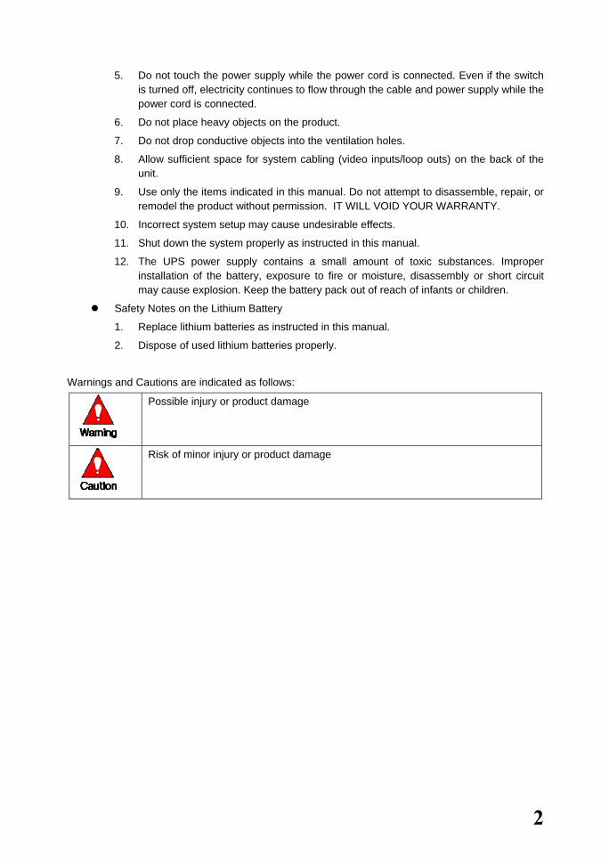
Warnings and Cautions are indicated as follows:
Possible injury or product damage
Risk of minor injury or product damage
3
Workhorse 120-4
C/O/N/T/E/N/T/S Workhorse 120-4
Statement of Compliance with FCC.......................................1
Warning...................................................................................................1
Cautions .................................................................................................1
C/O/N/T/E/N/T/S ...........................................................................................3 1. Overview..................................................................................................6
1-1. About the Product .....................................................................................................6 1-2. Major Features..........................................................................................................6 1-3. Components..............................................................................................................7
2. Installation and Connection...................................................................8 2-1. Name and Features of Each Part .............................................................................8
2-1-1. Front Part .......................................................................................................................................8 2-1-2. Rear Part ........................................................................................................................................9
2-2. Installation and Connection ....................................................................................10 2-2-2. Adding a Hard Drive ..................................................................................................................13 2-2-3. CD-RW/DVD-RW ......................................................................................................................17
3. Operation and Setup Tools ..................................................................18 3-1. Front Buttons ..........................................................................................................18 3.2 Remote Control ........................................................................................................19 3-3. Mouse .....................................................................................................................22
4. System Operation .................................................................................23 4-1. Starting and Shutting down the System..................................................................23
4-1-1. Starting the System......................................................................................................................23 4-1-2. Shutting down the System ...........................................................................................................23
4-2. System Login ..........................................................................................................25 4-2-1. User Account ...............................................................................................................................25 4-2-2. Login ...........................................................................................................................................25
4-3. Monitoring ...............................................................................................................27 4-3-1. Divided Screen and Automatic Screen Conversion .....................................................................27
4-4. Audio Live, Recording, and Playing........................................................................28 4-4-1. Audio Live and Recording Setup.................................................................................................28 4-4-2. Changing the Audio Live Channel ..............................................................................................29

4
4-5. Viewing System Information and Changing the Display Setup ..............................31 4-5-1. Viewing System Information.......................................................................................................31 4-5-2. Brightness Control .......................................................................................................................33 4-5-3. Adjusting the Contrast .................................................................................................................33 4-5-4. Camera Control............................................................................................................................33 4-5-5. TV Control...................................................................................................................................34 4-5-6. Language .....................................................................................................................................34 4-5-7. Displaying/Hiding the Camera Name..........................................................................................35 4-5-8. Controlling the Screen Border .....................................................................................................35 4-5-9. Reset ............................................................................................................................................36
4-6. System Log .............................................................................................................37 4-6-1. Log Type .....................................................................................................................................37 4-6-2. Viewing the System Log .............................................................................................................37
4-7. Record.....................................................................................................................40 4-7-1. Recording Type ...........................................................................................................................40 4-7-2. Recording Setup ..........................................................................................................................40 4-7-3. Viewing the Recording Status .....................................................................................................40 4-7-4. Starting and Stopping Record All ................................................................................................41 4-7-5. Watermark ...................................................................................................................................42
4-8. Search.....................................................................................................................43 4-8-1. Selecting Search Mode ................................................................................................................43 4-8-2. Search Method.............................................................................................................................44 4-8-3. Selecting the Search Tool ............................................................................................................44 4-8-4.Multi-channel ...............................................................................................................................47 4-8-5. Multi-hour....................................................................................................................................48 4-8-6. Multi-date ....................................................................................................................................49
4-9. Play .........................................................................................................................51 4-9-1. Selecting Play Mode....................................................................................................................51 4-9-2. Playing and Controlling the Play Speed ......................................................................................53 4-9-3. Playing on a Divided Screen........................................................................................................54 4-9-4. Changing the Audio Channel.......................................................................................................56 4-9-5. Mute ............................................................................................................................................57 4-9-6. Smart Search................................................................................................................................58 4-9-7. Digital Zoom-in ...........................................................................................................................61
4-10. Backup ..................................................................................................................63 4-11. PTZ Camera Control.............................................................................................67
4-11-1. Conditions for Using PTZ..........................................................................................................67 4-11-2. Shifting to PTZ Mode................................................................................................................67 4-11-3. PTZ Control...............................................................................................................................68
5
5. System Setup ........................................................................................70 5-1. Main Setup..............................................................................................................70
5-1-1. Starting the Main Setup ...............................................................................................................70 5-1-2. Recording Setup ..........................................................................................................................71 5-1-3. Recording Schedule .....................................................................................................................89 5-1-4. System .........................................................................................................................................95 5-1-5.Storage Device............................................................................................................................107 5-1-6.NTP ............................................................................................................................................117 5-1-7. Advanced...................................................................................................................................121
5-2. Additional Setup....................................................................................................125 5-2-1. Selecting Additional Setup ........................................................................................................125 5-2-2.PTZ Setup...................................................................................................................................126 5-2-3. Network Setup ...........................................................................................................................130
1. Rugged Vision Viewer (Web monitoring).......................................... 144 1-1.Access....................................................................................................................144 1-2.Description of the Basic Features..........................................................................146 1-3. Audio.....................................................................................................................146 1-4. Color Adjust ..........................................................................................................147 1-5. DVR Network Setting ............................................................................................147 1-6. Viewing a Divided Screen.....................................................................................149 1-7.Search and Playback .............................................................................................150
1-7-2. Search Method...........................................................................................................................150 1-7-3. Search and Play .........................................................................................................................150 1-7-4. Playback Control .......................................................................................................................152 1-7-5. Screen Description.....................................................................................................................152
1-8. DVR Setup ............................................................................................................153 2. Quick Viewer .......................................................................................154
2-1. File Play ................................................................................................................155 2-2. Description of Buttons...........................................................................................155 2-3. Version Information...............................................................................................156
A/P/P/E/N/D/I/X ........................................................................................157 1. PTZ Camera Protocol .......................................................................158 2. Recommended HDD.........................................................................158 3. Recommended USB 2.0 Device.......................................................159
Memory Stick......................................................................................................159 2.5" Portable USB HDD......................................................................................159 CD-RW, DVD-RW ..............................................................................................159

6
1. Overview
1-1. About the Product Workhorse 120-4 is a digital video monitoring system. This product can display and record, at a high resolution rate, the video data of up to four cameras. Front buttons, remote control, and mouse are provided for the user’s convenience; along with network features including monitoring and remote system setup. Workhorse 120-4 supports up to 120/100 (NTSC/PAL) fps.
1-2. Major Features Stable Standalone DVR (embedded Linux) Video output
- Loop output: 4 BNC - Monitor output: 1 BNC, 1 VGA
Simultaneous real-time display, recording, and playback at 120/100 (NTSC/PAL) fps Resolution
- NTSC: 320×240, 640×240, 640×480 - PAL: 320×288, 640×288, 640×576
Compression type: MPEG4 (video)/G.726 (audio) Backup/Copy: Ethernet, USB2.0, Built-in CD-RW System operation: Front buttons/Remote control/Network/USB2.0 mouse/System
control 2-channel audio input Various-network-interfaces
- Cable modem, Ethernet, ADSL/DHCP client System automation (all features are remote controllable) NTP support Various-recording-modes
- Auto, Continuous, Event (sensor, motion, sound) recording Recording schedule Multi-language support, Automatic emailing PTZ control through RS485 communication Remote monitoring software, Remote monitoring through the web browser, PDA
viewer Storage device
- Internal storage device: Max. of 4HDD, 2TB
7
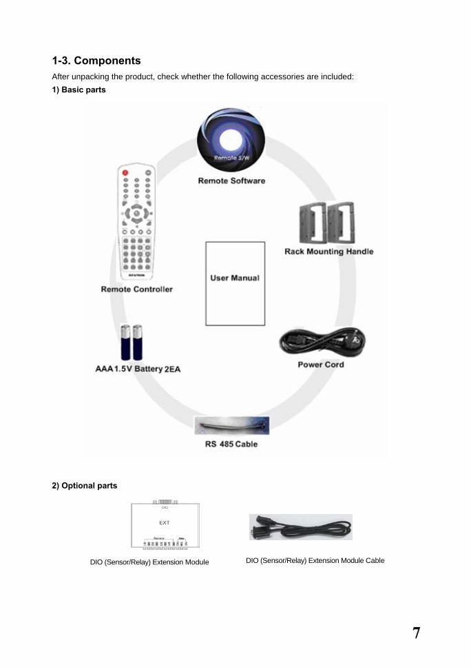
1-3. Components After unpacking the product, check whether the following accessories are included: 1) Basic parts
2) Optional parts
DIO (Sensor/Relay) Extension Module DIO (Sensor/Relay) Extension Module Cable

8
2. Installation and Connection 2-1. Name and Features of Each Part Buttons are conveniently located on the front panel of the Workhorse 120-4, and various interfaces, on its rear panel. Workhorse 120-4 can be easily installed in a standard rack using the rack mounting handles (on the left and right sides). 2-1-1. Front Part
No Name Features
1 Remote The green light is ON when the remote control is accessing the DVR
2 Network The green light is ON when the DVR is being accessed through the network
3 Backup The green light is ON when the DVR is making a backup
4 HDD The green light is turned ON when the hard drive is operating.
5 Alarm The red light is ON when an alarm is triggered.
6 CD-RW/DVD-RW CD-RW/DVD-RW installation slot
7 Numeric buttons Numeric buttons
8 USB External backup device or USB mouse connection
9 Remote control sensor Remote control reception sensor
10 Power System power ON/OFF or Selection button

9
2-1-2. Rear Part
No Name Features Form
1 AC in Power cable connection to the body
2 Ethernet ADSL, Cable modem, and Ethernet 10/100 Base-T connection RJ-45
3 RS-232C PSTN/ISDN modem connection or Serial cable connection for system upgrade
D-SUB 9 pin
4 RS485 PTZ camera control cable connection RJ-11 6-pin
5 VGA VGA monitor connection D-SUB 15 pin
6 TV CCTV monitor connection BNC
7 Video in Video camera connection BNC
8 Audio in Audio input connection (line only input)
- 2-line RCA
9 Audio out Audio output connection (line only output)
-1-line RCA
10 DIO DIO (sensor/relay) extension module connection D-SUB 25 pin
11 Video out
(loop-out) Video signal loop-out connection BNC
10
2-2. Installation and Connection 2-2-1. Basic Connection
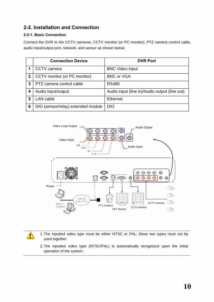
Connect the DVR to the CCTV cameras, CCTV monitor (or PC monitor), PTZ camera control cable, audio input/output port, network, and sensor as shown below:
Connection Device DVR Port
1 CCTV camera BNC Video input
2 CCTV monitor (or PC monitor) BNC or VGA
3 PTZ camera control cable RS485
4 Audio input/output Audio input (line in)/Audio output (line out)
5 LAN cable Ethernet
6 DIO (sensor/relay) extended module DIO
1. The inputted video type must be either NTSC or PAL; these two types must not be
used together.
2. The inputted video type (NTSC/PAL) is automatically recognized upon the initial operation of the system.
Video Loop Output Audio Output
Audio Input
Video Input
PTZ Camera CRT Monitor
CCTV Monitor
CCTV Camera
Power

11
(1) PTZ camera
� To use a PTZ camera, connect the control cable to the RS485 connector.
RS485 uses the RJ-11 6-pin type. Below is the pin arrangement:
Pin 1 2 3 4 5 6
RS485 GND TR+ TR- TR+ TR- GND
(2) Audio input/output
There are two audio input ports and one audio output port.
(3) DIO (sensor/relay) extension module
Connect the DIO (sensor/relay) extension module to the DIO connector on the rear side using a D-SUB 25-type extension cable.
A) External sensor connection option
The DIO (sensor/relay) extension module consists of four sensor input ports and one relay output port.
DIO (sensor/relay) extended module
Sensor input port
Audio Output
Audio Intput
12
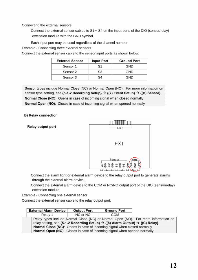
Connecting the external sensors � Connect the external sensor cables to S1 ~ S4 on the input ports of the DIO (sensor/relay)
extension module with the GND symbol.
� Each input port may be used regardless of the channel number. Example - Connecting three external sensors Connect the external sensor cable to the sensor input ports as shown below:
External Sensor Input Port Ground Port Sensor 1 S1 GND Sensor 2 S3 GND Sensor 3 S4 GND
Sensor types include Normal Close (NC) or Normal Open (NO). For more information on sensor type setting, see {5-1-2 Recording Setup} {(7) Event Setup} {(B) Sensor}. Normal Close (NC): Opens in case of incoming signal when closed normally Normal Open (NO): Closes in case of incoming signal when opened normally
B) Relay connection
Relay output port
� Connect the alarm light or external alarm device to the relay output port to generate alarms
through the external alarm device. � Connect the external alarm device to the COM or NC/NO output port of the DIO (sensor/relay)
extension module. Example - Connecting one external sensor Connect the external sensor cable to the relay output port:
External Alarm Device Output Port Ground Port Relay 1 NC or NO COM
Relay types include Normal Close (NC) or Normal Open (NO). For more information on relay setting, see {5-1-2 Recording Setup} {(8) Alarm Output} {(C) Relay}. Normal Close (NC): Opens in case of incoming signal when closed normally Normal Open (NO): Closes in case of incoming signal when opened normally
13
2-2-2. Adding a Hard Drive
Up to four hard drive s may be installed in the system using two hard drive cables.
Each hard drive cable can connect two hard drive s, which must be configured in master-slave structure.
In the absence of CD-RW, two hard drive bays are installed: one on the right and the other on the left. If there is a CD-RW, however, only two hard drive bays are installed on the right.
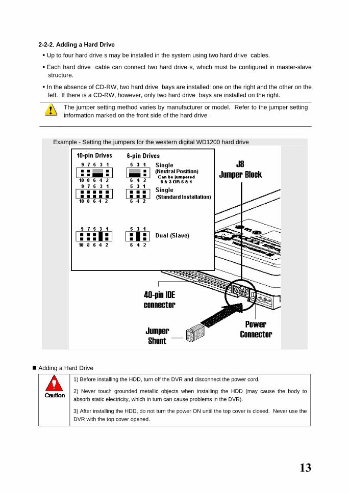
The jumper setting method varies by manufacturer or model. Refer to the jumper setting information marked on the front side of the hard drive .
Example - Setting the jumpers for the western digital WD1200 hard drive
Adding a Hard Drive
1) Before installing the HDD, turn off the DVR and disconnect the power cord.
2) Never touch grounded metallic objects when installing the HDD (may cause the body to absorb static electricity, which in turn can cause problems in the DVR).
3) After installing the HDD, do not turn the power ON until the top cover is closed. Never use the DVR with the top cover opened.

14
� Before turning OFF the power, shut down the system first. � Unscrew and open the upper case.
� Unscrew the hard drive bay using a
screwdriver and separate the hard drive bay from the body.
� Insert the hard drives into the hard drive bay

15
� Connect the hard drive power cable and hard drive connection cable to the corresponding plugs.
Connect the hard drive connection cable as follows:
1. Connecting one hard drive connection cable
1) Installing one HDD
System Master
Primary (Master) E- IDE Connector 0 Connector 1
2) Installing two HDDs
System MasterSlave
Primary (Master) E- IDE Connector 0 Connector 1
2. Connecting two hard drive connection cables
1) Installing three HDDs
System MasterSlave
Primary (Master) E- IDE Connector 0 Connector 1
System Master
Secondary (Slave) E- IDE Connector 0 Connector 1
2) Installing four HDDs
System MasterSlave
Primary (Master) E- IDE Connector 0 Connector 1
System MasterSlave
Secondary (Slave) E- IDE Connector 0 Connector 1

16
� Place the hard drive bay back in the DVR and fasten with screws.
� Close the upper case and fasten the screws.
� Turn the power ON and start the system.
After adding a hard drive, select {Main Setup} -> {Storage Device} -> {Local} -> {3. Manage Local Storage Device}. For more information, see {5. System Setup} -> {5-1 Main Setup} -> {5-1-5 Storage Device}.
17
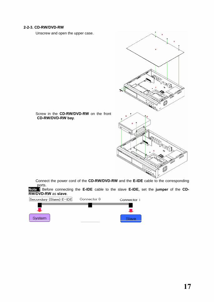
2-2-3. CD-RW/DVD-RW � Unscrew and open the upper case.
� Screw in the CD-RW/DVD-RW on the front
CD-RW/DVD-RW bay.
� Connect the power cord of the CD-RW/DVD-RW and the E-IDE cable to the corresponding
ports. Note ! Before connecting the E-IDE cable to the slave E-IDE, set the jumper of the CD-RW/DVD-RW as slave.

18
3. Operation and Setup Tools The user can operate Workhorse 120-4 easily using the front buttons, remote control, and mouse.
3-1. Front Buttons
No. Name Features
1 Remote The green light is ON when the remote control is accessing the DVR
2 Network The green light is ON when the DVR is being accessed through the network
3 Backup The green light is ON when the DVR is making a backup
4 HDD The green light is turned ON when the hard drive is operating.
5 Alarm The red light is ON when an alarm is triggered.
6 CD-RW/DVD-RW CD-RW/DVD-RW installation slot
7 Numeric buttons Numeric buttons
8 USB External backup device or USB mouse connection
9 Remote control sensor Remote control reception sensor
10 Power System power ON/OFF or Selection button
The front buttons are used only for inputting numeric data. Use the mouse or remote control
for the other features.
Menu Key Type 1st 2nd 3rd 4th 5th Power Short 1CH full 2CH full 3CH full 4CH full Quad Power Live Long X X X Status X Select Short 1 3 5 7 9 ESC
Password Long 2 4 6 8 0 Select Short 1CH full 2CH full 3CH full 4CH full Quad X
Playback Long X X X X X Select

19
3.2 Remote Control A. Basic control buttons
Power Turns the system ON or OFF
Lock Disables the mouse, remote
control, and front buttons
~ Number Used to input numeric data
ID setting
Used to set the remote control ID
ESC
Exits the current menu or selects the upper menu
B. System operation and setup buttons
MAIN SETUP
Main setup Used to set up the recording, recording schedule, and system
APP. SETUP
APP setup Used to set up the PTZ and network
PTZ
PTZ Changes the PTZ camera
control mode
SEARCH
Search Searches recorded images
Move
Moves an item or changes the display mode
Select
Selects an item or converts screens sequentially
Setting the remote control ID
Example - Setting the remote control ID as 1
Select the [ID] button and input the two-digit remote control ID. Afterward, press the [ID] button
again.
To control all DVRs with different IDs, set the remote control ID as 999.
20
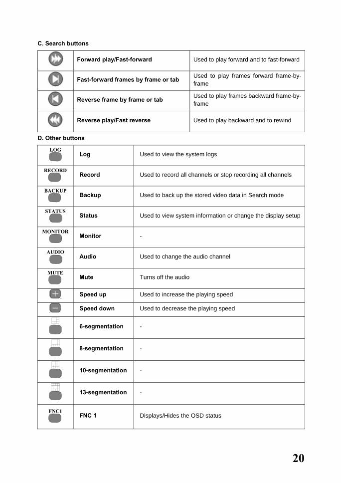
C. Search buttons
Forward play/Fast-forward Used to play forward and to fast-forward
Fast-forward frames by frame or tab Used to play frames forward frame-by-
frame
Reverse frame by frame or tab Used to play frames backward frame-by-
frame
Reverse play/Fast reverse Used to play backward and to rewind
D. Other buttons
LOG
Log Used to view the system logs
RECORD
Record Used to record all channels or stop recording all channels
BACKUP
Backup Used to back up the stored video data in Search mode
STATUS
Status Used to view system information or change the display setup
MONITOR
Monitor -
AUDIO
Audio Used to change the audio channel
MUTE
Mute Turns off the audio
Speed up Used to increase the playing speed
Speed down Used to decrease the playing speed
6-segmentation -
8-segmentation -
10-segmentation -
13-segmentation -
FNC1
FNC 1 Displays/Hides the OSD status

21
FNC 2~4 FNC 2~4 -

22
3-3. Mouse The user can operate the system using a USB mouse.
To go to the On Screen Display (OSD) menu, right-click as shown below:
To close the OSD menu, right-click once again.
To execute the OSD menu, click each button.
To exit the sub-menu, just right-click.
No Name Features
1 Lock Disables the mouse, remote control, and touch screen 2 Main setup Used to set up the recording, recording schedule, and system 3 Additional setup Used to set up the PTZ and network 4 PTZ Changes the PTZ camera control mode 5 Search Searches recorded images 6 Log Used to view the system log list 7 Record Used to record all channels or stop recording all channels 8 Status Used to view system information or change the display setup 9 Monitor - 10 Voice Used to change the audio channel 11 F1 Displays/Hides the OSD status 12 F2 - 13 F3 - 14 F4 -

23
4. System Operation 4-1. Starting and Shutting down the System 4-1-1. Starting the System
The default password of the local administrator is “00000.” To change the password, select {Main Setup} {System} {Local Administrator’s Password}.
� With the power connected to the body, press the Power button on the remote control.
� The Remote, Network, Backup, and Alarm LEDs on the front panel are then turned ON.
� Input the local administrator’s password using the numeric buttons.
� Once the correct password is inputted, the system is initialized, and the initial screen appears.
� After the system is initialized and started, the video of all connected channels is displayed.
Note: The password may contain up to five digits. If the password has less than five digits, press the
button.
When using a five-digit password, however, the user does not need to press the button.
The user can input a number using the front buttons as shown below:
Odd number: Short-press Even number: Long-press
Input initialization: Press the [Power] button.
4-1-2. Shutting down the System
The default password of the local administrator is “00000.”
To change the password, select {Main Setup} {System} {Local Administrator’s Password}.

24
� Press the Power button on the remote control.
� Input the system administrator’s password using the numeric buttons and press the button.
� Once the correct password is inputted, all lights on the front part blink, and a warning sound is
generated for approximately 20 seconds before the system shuts down.
� If an incorrect password is inputted, a warning message is displayed followed by the previous
screen as shown below:
The user can input a number using the front buttons as shown below: Odd number: Short-press Even number: Long-press Input initialization: Press the [Power] button.
Incorrect Password!!
25
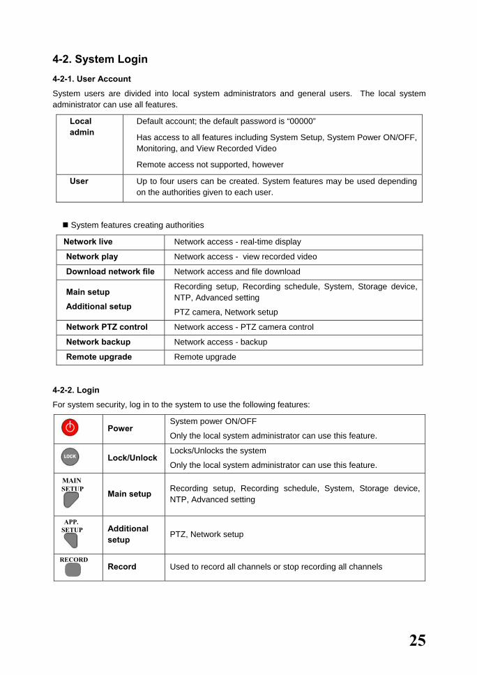
4-2. System Login 4-2-1. User Account
System users are divided into local system administrators and general users. The local system administrator can use all features.
Local admin
Default account; the default password is “00000”
Has access to all features including System Setup, System Power ON/OFF, Monitoring, and View Recorded Video
Remote access not supported, however
User Up to four users can be created. System features may be used depending on the authorities given to each user.
System features creating authorities
Network live Network access - real-time display
Network play Network access - view recorded video
Download network file Network access and file download
Main setup
Additional setup
Recording setup, Recording schedule, System, Storage device, NTP, Advanced setting
PTZ camera, Network setup
Network PTZ control Network access - PTZ camera control
Network backup Network access - backup
Remote upgrade Remote upgrade
4-2-2. Login
For system security, log in to the system to use the following features:
Power
System power ON/OFF
Only the local system administrator can use this feature.
Lock/Unlock
Locks/Unlocks the system
Only the local system administrator can use this feature.
MAIN SETUP
Main setup Recording setup, Recording schedule, System, Storage device, NTP, Advanced setting
APP. SETUP
Additional setup PTZ, Network setup
RECORD
Record Used to record all channels or stop recording all channels
26
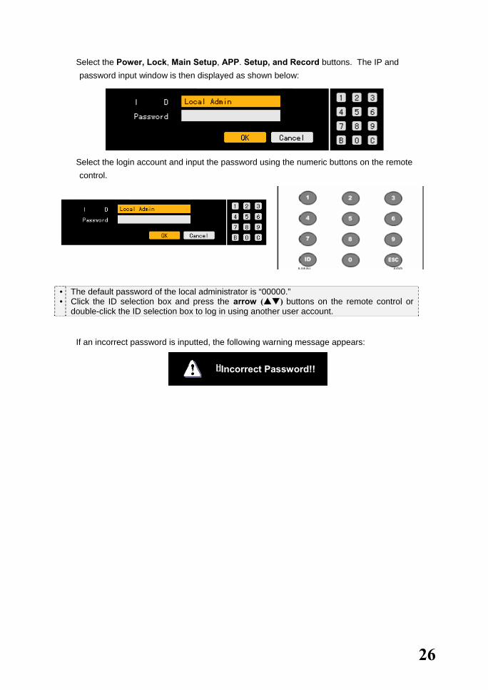
� Select the Power, Lock, Main Setup, APP. Setup, and Record buttons. The IP and password input window is then displayed as shown below:
� Select the login account and input the password using the numeric buttons on the remote
control.
• •
The default password of the local administrator is “00000.” Click the ID selection box and press the arrow ( ) buttons on the remote control or double-click the ID selection box to log in using another user account.
� If an incorrect password is inputted, the following warning message appears:
Incorrect Password!!

27
4-3. Monitoring Once the system starts, video data from the CCTV/VGA monitor is displayed on the 4-divided screen.
The user can choose from full screen and 4-divided screen.
4-3-1. Divided Screen and Automatic Screen Conversion
View all (4 sub-screens)
To view the video of a certain channel, select the desired channel by pressing the numeric buttons.
Press the arrow up button on the remote control. Pressing the arrow up each time causes the next screen to be selected.
To view the video of Channel No. 1, press [1·2], to view the video of Channel No. 2 Press [3·4], to view the video of Channel No. 3 [5·6], and. to view the video of Channel No. 4 press the [7·8] button.
4-divided screen (1 screen)
Press the Left button on the remote control and short-press the [9-0] button.
On the 4-divided screen, double-click the channel to enlarge its video.
Double-click any area on the View All window to convert into a 4-divided screen.
Automatic screen conversion
In Live Full Screen mode, press the button on the remotecontrol.
To convert the screen automatically, press the button on theremote control again.
The user can convert the screens in current division mode.
To set the conversion interval, Press the buttons on theremote control.
Select to increase the time.
To disable the conversion mode, shift to 4-divided View mode.
28
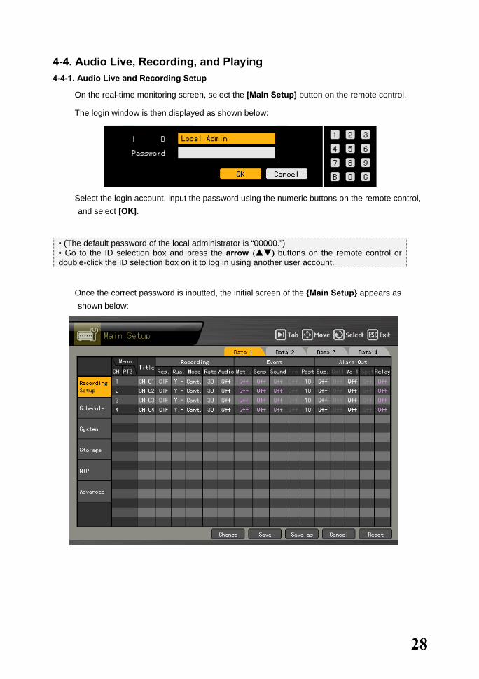
4-4. Audio Live, Recording, and Playing 4-4-1. Audio Live and Recording Setup
� On the real-time monitoring screen, select the [Main Setup] button on the remote control.
� The login window is then displayed as shown below:
� Select the login account, input the password using the numeric buttons on the remote control,
and select [OK].
• (The default password of the local administrator is “00000.”) • Go to the ID selection box and press the arrow ( ) buttons on the remote control or double-click the ID selection box on it to log in using another user account.
� Once the correct password is inputted, the initial screen of the {Main Setup} appears as shown below:
29
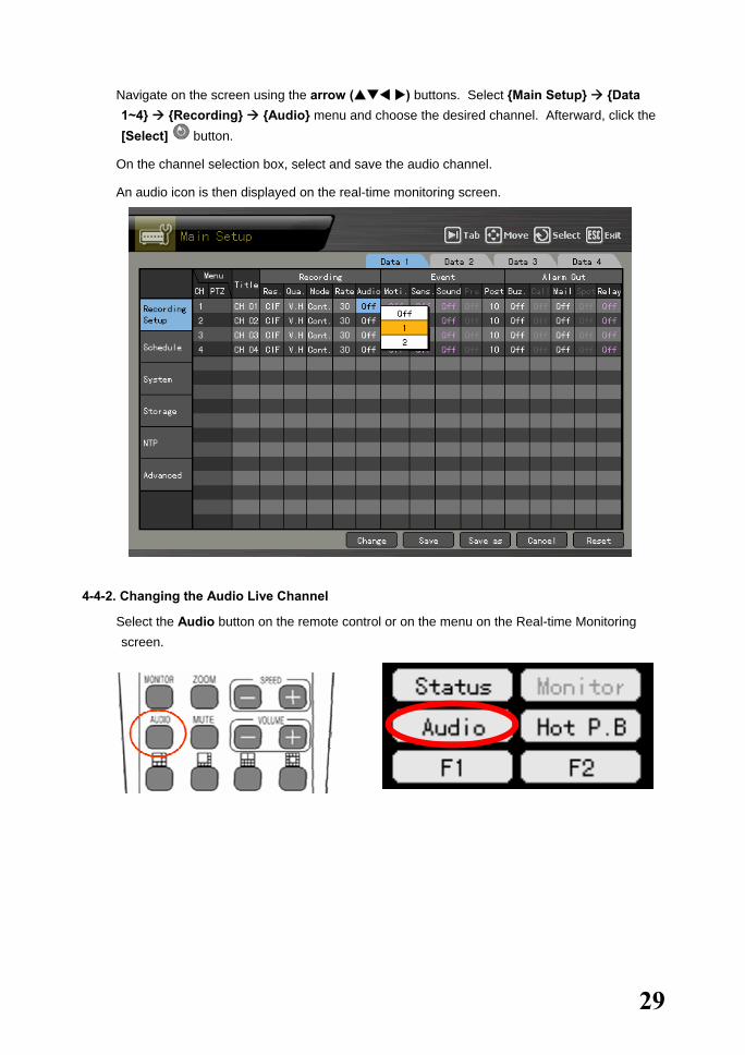
� Navigate on the screen using the arrow ( ) buttons. Select {Main Setup} {Data 1~4} {Recording} {Audio} menu and choose the desired channel. Afterward, click the [Select] button.
� On the channel selection box, select and save the audio channel.
� An audio icon is then displayed on the real-time monitoring screen.
4-4-2. Changing the Audio Live Channel
� Select the Audio button on the remote control or on the menu on the Real-time Monitoring screen.

30
� The Audio icon and active window are then displayed on the channel, with the voice set on the real-time monitoring window as shown below:
� Change the window using the arrow ( ) buttons and click the [Select] button to select an audio channel.
� The real-time monitoring screen is then selected, and the voice for the selected channel, outputted.

31
4-5. Viewing System Information and Changing the Display Setup Workhorse 120-4 displays basic system information through the OSD on the real-time screen to enable the user to monitor the screen, view system information, and set the screen.
Selecting the [Status] button causes the setup menus to be displayed in the following order:
Channel selection window
Activation mode
The channel selection window can be moved. At this time, the border of the channel screen is displayed in orange.
Selection mode
The channel is selected. At this time, the border of the channel screen is displayed in blue.
Viewing a divided screen
Pressing the buttons in Brightness, Contrast, or Camera Control mode enables monitoring the video in full screen or 4-divided screen.
4-5-1. Viewing System Information
Button operation
� To view product information, press the Status button on the remote control or go to the Status

32
menu.
1. ID Product ID (1~99)
(used for remote control by ID)
2. Name Product name
3. Software version Software version (build number)
4. Hardware version Hardware version (equipment type)
5. Front firmware version Firmware version on the front part
6. Video mode Video mode (NTSC/PAL)
7. HDD information Hard drive
Total space Total space
Used space Used space
Free space Remaining space
Start day Recording start date (date changed)
End day Recording end date (date changed)
8. Network setup Network setup status
IP address IP address
9. Overwrite Overwrite status
10. DDNS server Domain name, OFF/ACT
33
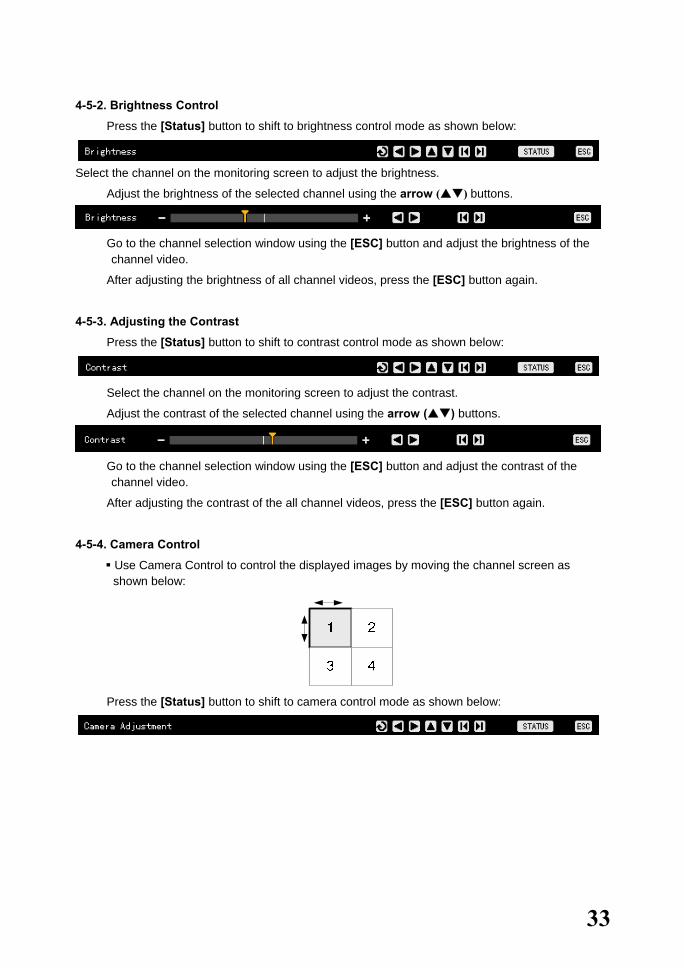
4-5-2. Brightness Control
� Press the [Status] button to shift to brightness control mode as shown below:
Select the channel on the monitoring screen to adjust the brightness.
� Adjust the brightness of the selected channel using the arrow ( ) buttons.
� Go to the channel selection window using the [ESC] button and adjust the brightness of the
channel video.
� After adjusting the brightness of all channel videos, press the [ESC] button again.
4-5-3. Adjusting the Contrast
� Press the [Status] button to shift to contrast control mode as shown below:
� Select the channel on the monitoring screen to adjust the contrast.
� Adjust the contrast of the selected channel using the arrow ( ) buttons.
� Go to the channel selection window using the [ESC] button and adjust the contrast of the
channel video.
� After adjusting the contrast of the all channel videos, press the [ESC] button again.
4-5-4. Camera Control
Use Camera Control to control the displayed images by moving the channel screen as shown below:
� Press the [Status] button to shift to camera control mode as shown below:

34
� Select the channel on the monitoring screen to control the camera.
� Adjust the camera of the selected channel using the arrow ( ) buttons.
� Go to the channel selection window using the [ESC] button and adjust the camera of the channel video.
� After adjusting the camera of the channel video, press the [ESC] button again.
Moving the monitor up, down, right, or left excessively may cause a black or gray part to appear on the screen. This is a normal response to excessive movement. A proper control range is achieved when there is no black or gray parts on the screen.
4-5-5. TV Control
Use TV Control to adjust the images displayed on the CCTV monitor by moving the CCTV monitor screen up, down, right, or left as shown below:
� Press the [Status] button to shift to TV control mode as shown below:
� Adjust the CCTV monitor screen using the arrow ( ) buttons as shown below:
� After adjusting the video, press the [ESC] button.
Moving the monitor up, down, right, or left excessively may cause a black or gray part to appear on the screen. This is a normal response to excessive movement. A proper control range is achieved when there is no black or gray parts on the screen.
4-5-6. Language
The user can select the language for the On Screen Display (OSD) menu of the system. � Press the [Status] button to shift to language selection mode as shown below:

35
� Press the [Select] button. On the language selection menu as shown below, select the language using the arrow ( ) buttons and press the [ESC] button:
4-5-7. Displaying/Hiding the Camera Name
Displays/Hides each channel on the monitoring screen
� Press the [Status] button to display/hide the camera name as shown below:
� Press the [Select] button. On the ON/OFF menu as shown below, select ON or OFF using the arrow ( ) buttons and press the [Select] button.
4-5-8. Controlling the Screen Border
Used to display/hide the screen border and to control the border form, thickness, transparency, and color
� To display/hide the border as shown below, press the [Status] button:
� Press the [Select] button. On the setting menu as shown below, select the desired item using the arrow ( ) buttons.
� After setting the selected item, save the setting and press the [Select] button.
� After setting each field, press the [ESC] button to exit the borderline setting mode.
36
Border setting fields Field Setting Description
ON Displays the border Mode OFF Hides the border
Internal Hides the external borderline Form All Displays all borderlines
Width 2, 4 Sets the width Transparency 10%, 25%, 50%, 75%, 100% Sets the transparency Color Black, White, Red, Green, Blue Sets the color of the border
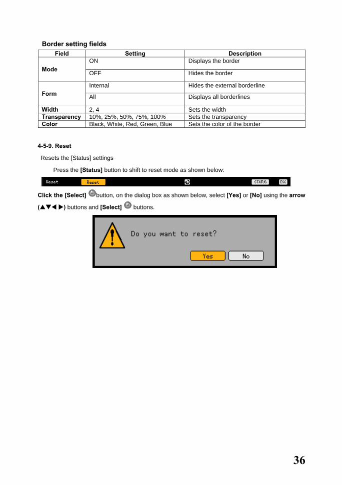
4-5-9. Reset
Resets the [Status] settings
� Press the [Status] button to shift to reset mode as shown below:
Click the [Select] button, on the dialog box as shown below, select [Yes] or [No] using the arrow
( ) buttons and [Select] buttons.

37
4-6. System Log Workhorse 120-4 records the logs of all operations including system power ON/OFF, system setup in/out, and network connection/disconnection.
4-6-1. Log Type
(1) General Logs related to power ON/OFF, file copy/backup failure, setup start/end, play, and other basic system operations
(2) Recording event Logs related to recording such as detection of motion, sensor, and sound
(3) Network Logs related to network operations such as network login, network logout, and network live
(4) Failure Logs related to operation failures such as signal loss and network connection failure
(5) All Logs related to all system operations
4-6-2. Viewing the System Log
� In real-time monitoring mode, press the [Log] button on the remote control or [Log] button on the menu.
� The initial menus of the log list are then displayed as shown below:

38
� On the active calendar window, select the search date using the arrow ( ) buttons
and [Select] buttons as shown below:
Viewing time change-related log data
The stored data folder is updated each time the user changes the time. On the other hand, a blue triangular icon is displayed on the date each time a change is made in the date on the calendar window. Otherwise, a red triangular icon is displayed on the unchanged date. To view the log details, select the date with a red icon. Selecting a date with a blue icon causes the changed date list to appear.
� Select the (new) date on the calendar window to display the log list as shown below:

39
� Navigate on the screen using the arrow ( ) buttons and check the logs by time and type.
� The user can check the logs by time and type on each page using the [TAB] buttons.
� Press the [Play] button on the selected log to play the recorded video for the corresponding
time.
� On the recorded video screen, press the [Play] button.
0 min currently displayed video’s position
Go to video of desired minute by moving the red- arrow
Recorded video exists up to this minute Play speed control
Step backward
Fast backward Backward play
Pause 60 min
Step forward Fast forward
Forward play
Hide menu bar
Recorded video is played each second. Example - The user can play the video from the 19:45:16 log by selecting 19:45:16.
� To return to the previous log list, press the [ESC] button.
40
4-7. Record 4-7-1. Recording Type
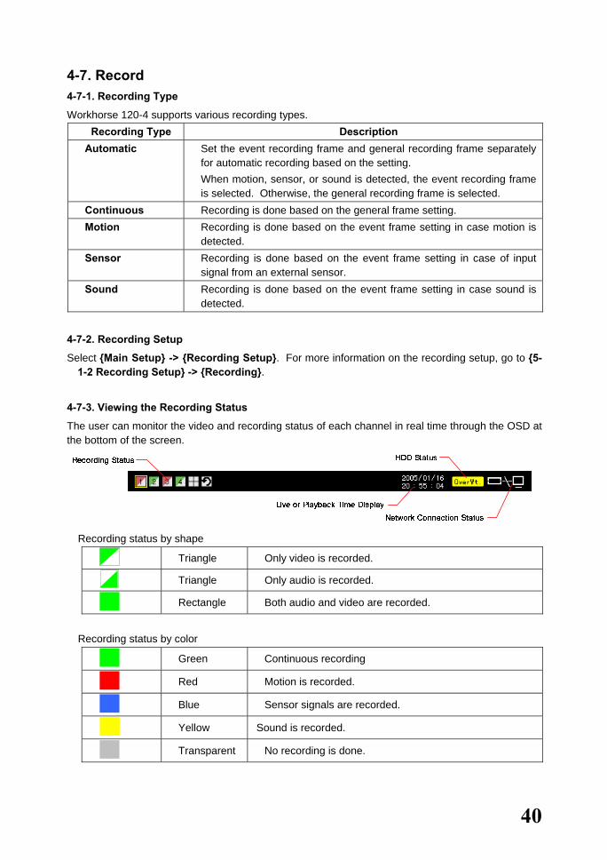
Workhorse 120-4 supports various recording types. Recording Type Description
Automatic Set the event recording frame and general recording frame separately for automatic recording based on the setting. When motion, sensor, or sound is detected, the event recording frame is selected. Otherwise, the general recording frame is selected.
Continuous Recording is done based on the general frame setting. Motion Recording is done based on the event frame setting in case motion is
detected. Sensor Recording is done based on the event frame setting in case of input
signal from an external sensor. Sound Recording is done based on the event frame setting in case sound is
detected.
4-7-2. Recording Setup
Select {Main Setup} -> {Recording Setup}. For more information on the recording setup, go to {5-1-2 Recording Setup} -> {Recording}.
4-7-3. Viewing the Recording Status
The user can monitor the video and recording status of each channel in real time through the OSD at the bottom of the screen.
� Recording status by shape
Triangle Only video is recorded.
Triangle Only audio is recorded.
Rectangle Both audio and video are recorded.
� Recording status by color
Green Continuous recording
Red Motion is recorded.
Blue Sensor signals are recorded.
Yellow Sound is recorded.
Transparent No recording is done.
41
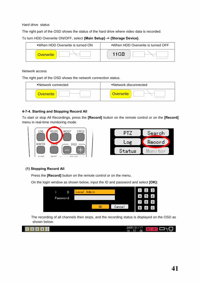
Hard drive status
The right part of the OSD shows the status of the hard drive where video data is recorded.
To turn HDD Overwrite ON/OFF, select {Main Setup} -> {Storage Device}.
When HDD Overwrite is turned ON When HDD Overwrite is turned OFF
Network access
The right part of the OSD shows the network connection status.
Network connected Network disconnected
4-7-4. Starting and Stopping Record All
To start or stop All Recordings, press the [Record] button on the remote control or on the [Record] menu in real-time monitoring mode.
(1) Stopping Record All
� Press the [Record] button on the remote control or on the menu.
� On the login window as shown below, input the ID and password and select [OK]:
� The recording of all channels then stops, and the recording status is displayed on the OSD as shown below:
Overwrite
Overwrite Overwrite
42
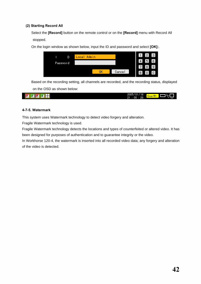
(2) Starting Record All
� Select the [Record] button on the remote control or on the [Record] menu with Record All
stopped.
� On the login window as shown below, input the ID and password and select [OK]:.
� Based on the recording setting, all channels are recorded, and the recording status, displayed
on the OSD as shown below:
4-7-5. Watermark
This system uses Watermark technology to detect video forgery and alteration.
Fragile Watermark technology is used.
Fragile Watermark technology detects the locations and types of counterfeited or altered video. It has
been designed for purposes of authentication and to guarantee integrity or the video.
In Workhorse 120-4, the watermark is inserted into all recorded video data; any forgery and alteration
of the video is detected.
43
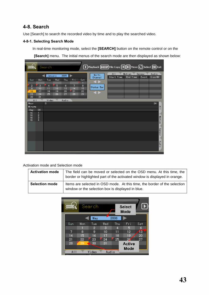
4-8. Search Use [Search] to search the recorded video by time and to play the searched video.
4-8-1. Selecting Search Mode
� In real-time monitoring mode, select the [SEARCH] button on the remote control or on the
[Search] menu. The initial menus of the search mode are then displayed as shown below:
Activation mode and Selection mode
Activation mode The field can be moved or selected on the OSD menu. At this time, the border or highlighted part of the activated window is displayed in orange.
Selection mode Items are selected in OSD mode. At this time, the border of the selection window or the selection box is displayed in blue.

44
4-8-2. Search Method
� Before selecting the date, go to the search method selection box by pressing the [TAB]
button. Afterward, select the Search method using the arrow ( ) buttons.
Multi-channel Searches the video of multiple channels for the defined time
Multi-date Searches the video of one channel for multiple dates in a certain time zone
Multi-hour Searches the video of one channel for the multiple time zones of one date
4-8-3. Selecting the Search Tool
� Before selecting the date, go to the search tool selection box by pressing the [TAB] button.
Afterward, select the search tool using the arrow ( ) buttons.
(1) Searching video using the bar graph
� Select the search date. The recorded video is then displayed in a bar graph as shown below:
Green Continuous recording
Red Motion is recorded.
Blue Sensor signals are recorded.
Yellow Sound is recorded.
Light blue Shows that recording was done before the time was changed

45
A) Multi-channel
Select the time using the arrow ( ) buttons.
B) Multi-time
Select the time and channel using the arrow ( ) buttons.
C) Multi-day
Select the time and channel using the arrow ( ) buttons.
46
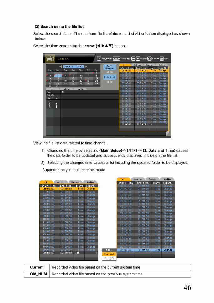
(2) Search using the file list
� Select the search date. The one-hour file list of the recorded video is then displayed as shown below:
� Select the time zone using the arrow ( ) buttons.
� View the file list data related to time change.
1) Changing the time by selecting {Main Setup}-> {NTP} -> {2. Date and Time} causes the data folder to be updated and subsequently displayed in blue on the file list.
2) Selecting the changed time causes a list including the updated folder to be displayed.
Supported only in multi-channel mode
Current Recorded video file based on the current system time
Old_NUM Recorded video file based on the previous system time

47
4-8-4. Multi-channel
Searches the video of multiple channels for the defined time
(1) Date search
� Select the search date using the arrow ( ) buttons and [Select] button on the active calendar window as shown below:
(2) Search time
� Select the search date on the calendar window. The recorded one-hour video of each channel is then displayed in a bar graph as shown below:
Green Continuous recording
Red Motion is recorded.
Blue Sensor signals are recorded.
Yellow Sound is recorded.
Light blue Shows that recording was done before the time was changed � Set the time by using the arrow ( ) or numeric buttons or moving the time indicator and
press the [Select] button.
Input numbers that are less than 10 in two digits using the numeric buttons, e.g., 01 for 1 and 02 for 2.
Viewing the status bar related to time change
1) After the changed folder is searched by the status bar, the bar for the corresponding time zone is displayed in light blue as shown below:
2) Selecting a changed time causes a list including the updated folder to be displayed as shown below:
� Supported only in multi-channel mode

48
(3) Minute
� Select the time. The recorded video of each channel is then displayed in a minute-unit bar graph.
� Define the starting point of the search time using the arrow ( ) and numeric buttons and click the [Select] button.
Input numbers that are less than 10 in two digits using the numeric buttons, e.g., 08 for 8 and 09 for 9.
4-8-5. Multi-hour
Searches the video of one channel for the multiple time zones of the same date
(1) Date search
� Select the search date using the arrow ( ) and [Select] buttons on the active calendar window as shown below:
21
49
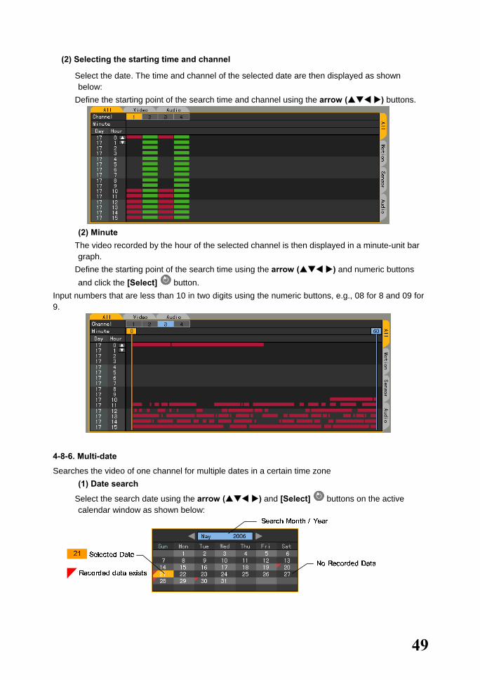
(2) Selecting the starting time and channel
� Select the date. The time and channel of the selected date are then displayed as shown below:
� Define the starting point of the search time and channel using the arrow ( ) buttons.
(2) Minute
� The video recorded by the hour of the selected channel is then displayed in a minute-unit bar graph.
� Define the starting point of the search time using the arrow ( ) and numeric buttons and click the [Select] button.
Input numbers that are less than 10 in two digits using the numeric buttons, e.g., 08 for 8 and 09 for 9.
4-8-6. Multi-date
Searches the video of one channel for multiple dates in a certain time zone (1) Date search
� Select the search date using the arrow ( ) and [Select] buttons on the active calendar window as shown below:

50
(2) Selecting the time and channel
� Select the date. The date list, time, and channel are then sorted in descending order.
� Select the time and channel by pressing the arrow ( ) buttons.
(3) Minute
� The recorded video of the selected channel is then displayed in a minute-unit bar graph.
� Define the starting point of the search time by using the arrow ( ) and numeric buttons and moving the minute indicator and click the [Select] button.
Input numbers that are less than 10 in two digits using the numeric buttons, e.g., 08 for 8 and 09 for 9.

51
4-9. Play 4-9-1. Selecting Play Mode
To shift to {Play} mode, press the [Play] button on the remote control or on the menu in {Search}, {Log}, or {Real-time Monitoring} mode. In log or real-time monitoring mode, only Multi-channel mode is allowed. To search and play, however, either Multi-channel or Multi-date or Multi-hour mode may be used.
(1) Search
� In {Search} mode, select Multi-channel, Multi-date, or Multi-hour.
� Set the play date, time, channel, or minute and select the [Play] button on the remote control
or at the upper center of the screen in {Search} mode.
� The playback screen for Multi-channel, Multi-date, and Multi-hour is then displayed as shown
below:
1) Multi-channel

52
2) Multi-time
3) Multi-day
53
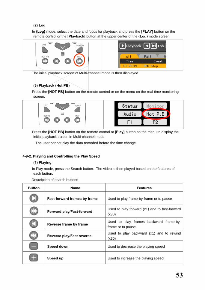
(2) Log
� In {Log} mode, select the date and focus for playback and press the [PLAY] button on the remote control or the [Playback] button at the upper center of the {Log} mode screen.
� The initial playback screen of Multi-channel mode is then displayed.
(3) Playback (Hot PB)
� Press the [HOT PB] button on the remote control or on the menu on the real-time monitoring screen.
� Press the [HOT PB] button on the remote control or [Play] button on the menu to display the initial playback screen in Multi-channel mode.
The user cannot play the data recorded before the time change.
4-9-2. Playing and Controlling the Play Speed
(1) Playing
� In Play mode, press the Search button. The video is then played based on the features of each button.
Description of search buttons
Button Name Features
Fast-forward frames by frame Used to play frame-by-frame or to pause
Forward play/Fast-forward
Used to play forward (x1) and to fast-forward (x30)
Reverse frame by frame
Used to play frames backward frame-by-frame or to pause
Reverse play/Fast reverse
Used to play backward (x1) and to rewind (x30)
Speed down Used to decrease the playing speed
Speed up Used to increase the playing speed
54
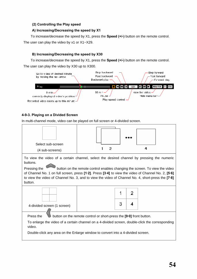
(2) Controlling the Play speed
A) Increasing/Decreasing the speed by X1
� To increase/decrease the speed by X1, press the Speed (+/-) button on the remote control.
The user can play the video by x1 or X1~X29.
B) Increasing/Decreasing the speed by X30
� To increase/decrease the speed by X1, press the Speed (+/-) button on the remote control.
The user can play the video by X30 up to X300.
4-9-3. Playing on a Divided Screen
In multi-channel mode, video can be played on full screen or 4-divided screen.
Select sub-screen
(4 sub-screens)
To view the video of a certain channel, select the desired channel by pressing the numeric buttons.
Pressing the button on the remote control enables changing the screen. To view the video of Channel No. 1 on full screen, press [1·2]. Press [3·4] to view the video of Channel No. 2, [5·6] to view the video of Channel No. 3, and to view the video of Channel No. 4, short-press the [7·8] button.
4-divided screen (1 screen)
Press the button on the remote control or short-press the [9·0] front button.
To enlarge the video of a certain channel on a 4-divided screen, double-click the corresponding video.
Double-click any area on the Enlarge window to convert into a 4-divided screen.

55
In multi-time or multi-day mode, video can be played on full screen or 4-divided, 9-divided, or 16-divided screen.
Select sub-screen
(16 sub-screens)
To view the video of a certain channel, select the desired channel by pressing the numeric buttons.
Pressing the button on the remote control or short-pressing the [1·2] front button enables viewing the next screen.
4-divided screen (4 screens)
To view the next screen, press the button on the remote control or short-press the [3·4] front button. On the 4-divided screen, double-click the video to view it on full screen. Double-click any area on the Enlarge window to convert into a 4-divided screen.
9-divided screen (2 screens)
To view the next screen, press the button on the remote control or short-press the [5·6]front button. On the 9-divided screen, double-click the video to view it on full screen. To go back tothe 9-divided screen, double-click the video again.
16-divided screen (1 screen)
Press the button on the remote control or short-press the [7·8] front button.
Double-click the video to be viewed on the channel. On the Enlarge window, double-click the videoto convert into a divided screen.

56
4-9-4. Changing the Audio Channel
� In Play mode, press the [Audio] button on the remote control.
� The Audio symbol is then displayed for the channel with the voice recording set together with an orange-colored activation window.
� Go to another window using the arrow ( ) buttons and press the [Select] button.
� The recorded audio of the selected channel is then played.
Drag the cursor to the upper right corner. On the popup menu, select the [Audio] button.

57
4-9-5. Mute
Use Mute to block the sound of the selected channel.
� In Play mode, press the [Mute] button on the remote control.
Drag the cursor to the upper right corner. On the popup menu, select [Mute]. An audio icon is then displayed on Channel No. 2.
58
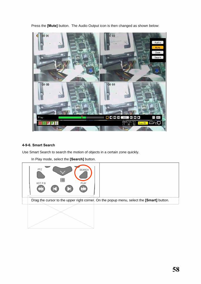
� Press the [Mute] button. The Audio Output icon is then changed as shown below:
4-9-6. Smart Search
Use Smart Search to search the motion of objects in a certain zone quickly.
� In Play mode, select the [Search] button.
Drag the cursor to the upper right corner. On the popup menu, select the [Smart] button.
59
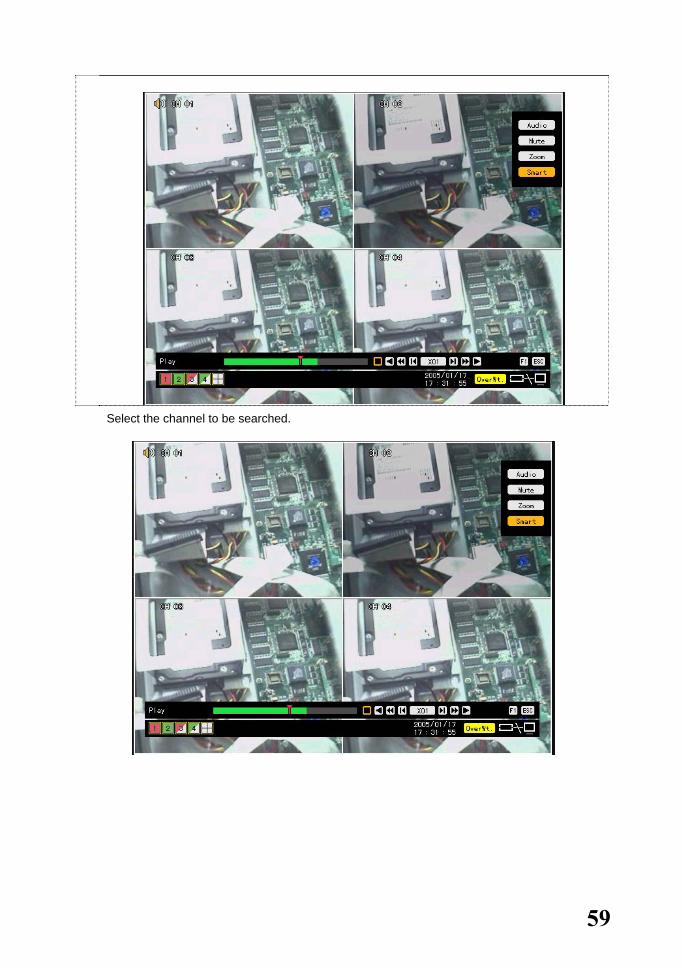
� Select the channel to be searched.
60
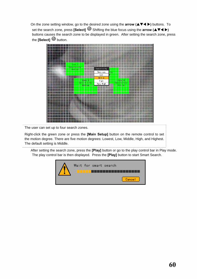
� On the zone setting window, go to the desired zone using the arrow ( ) buttons. To set the search zone, press [Select] Shifting the blue focus using the arrow ( ) buttons causes the search zone to be displayed in green. After setting the search zone, press the [Select] button.
The user can set up to four search zones.
Right-click the green zone or press the [Main Setup] button on the remote control to set the motion degree. There are five motion degrees: Lowest, Low, Middle, High, and Highest. The default setting is Middle.
� After setting the search zone, press the [Play] button or go to the play control bar in Play mode. The play control bar is then displayed. Press the [Play] button to start Smart Search.

61
� After Smart Search is completed, the following search window appears:
� The search zone where motion is detected turns green.
� The user can play the video searched via Smart Search using the following search buttons:
4-9-7. Digital Zoom-in
The user can enlarge a certain part while playing the video.
� In Play mode, press the [Zoom] button on the remote control.

62
Drag the cursor to the upper right corner. On the popup menu, select the [Zoom] button.
� On the active window, select a channel using the arrow ( ) buttons and press the [Select]
button.
� Selecting the [Zoom] button to zoom in/out the video from X2, X3 up to X½ causes the
selected channel to be displayed.
The user can select another channel using the arrow ( ) button on the zoom-in screen.
Clicking any point on the screen enables the user to change the direction.

63
4-10. Backup Workhorse 120-4 provides USB 2.0 and CD-RW/DVD-RW backup interfaces.
Before backing up the data, check whether the CD-RW/DVD-RW is installed or connect an external
hard drive with USB2.0 interface, an external CD-RW/DVD-RW, or any other storage device to the
USB2.0 port on the front side. Refer to the appendix for the list of supported external devices.
� Select {Search} – {Multi Channel} – {Minute} as shown below:
For the search method, refer to Section 4-8 Search.
� Press the [Backup] button on the remote control or go to the [Backup] menu at the center of
the {Search} mode screen.

64
� In the access device selection list, select one for the connected storage devices.
� Check the backup capacity and adjust the available space by using the arrow (▲▼ )
buttons or pressing the [Select] button.
Note! To back up a channel or cancel backup, go to the backup channel by using the
arrow (▲▼) buttons and pressing the [Select] button.
The backup channel is then displayed in red.
To change the backup time, go to the starting point of the backup time by selecting the button and change the minute bar using the arrow ( ) buttons.

65
� Select the [Backup] button at the upper center on the {Search} mode screen. The corresponding backup information is then displayed. Check the backup information and click [Yes] on the message window as shown below:
If the backup storage device has not been formatted, or in case the storage space is already in use, the following message appears:
To delete the data, select [Yes].
66
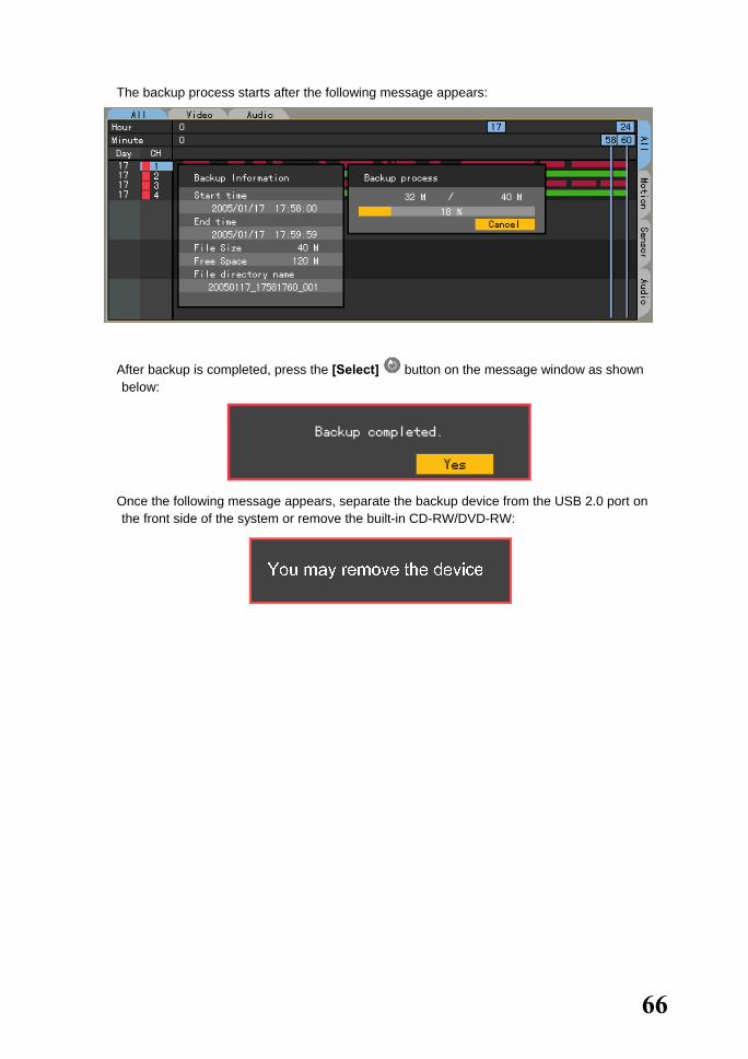
� The backup process starts after the following message appears:
� After backup is completed, press the [Select] button on the message window as shown below:
� Once the following message appears, separate the backup device from the USB 2.0 port on the front side of the system or remove the built-in CD-RW/DVD-RW:
67
4-11. PTZ Camera Control 4-11-1. Conditions for Using PTZ
� The PTZ camera must connect with the system.
� Select {Additional Setup} -> {PTZ Setup} and check whether the PTZ camera protocol is available.
For more information on PTZ camera setting, go to {Additional Setup} -> {PTZ Setup}.
4-11-2. Shifting to PTZ Mode
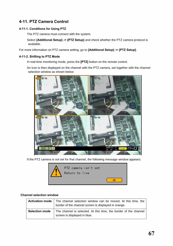
� In real-time monitoring mode, press the [PTZ] button on the remote control.
� An icon is then displayed on the channel with the PTZ camera, set together with the channel selection window as shown below:
� If the PTZ camera is not set for that channel, the following message window appears:
Channel selection window
Activation mode The channel selection window can be moved. At this time, the border of the channel screen is displayed in orange.
Selection mode The channel is selected. At this time, the border of the channel screen is displayed in blue.
68
4-11-3. PTZ Control
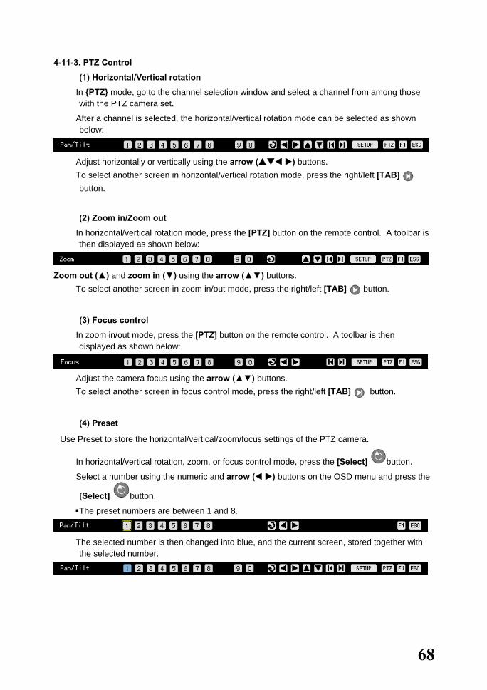
(1) Horizontal/Vertical rotation
� In {PTZ} mode, go to the channel selection window and select a channel from among those with the PTZ camera set.
� After a channel is selected, the horizontal/vertical rotation mode can be selected as shown below:
� Adjust horizontally or vertically using the arrow ( ) buttons. � To select another screen in horizontal/vertical rotation mode, press the right/left [TAB]
button.
(2) Zoom in/Zoom out
� In horizontal/vertical rotation mode, press the [PTZ] button on the remote control. A toolbar is then displayed as shown below:
Zoom out (▲) and zoom in (▼) using the arrow (▲▼) buttons.
� To select another screen in zoom in/out mode, press the right/left [TAB] button.
(3) Focus control
� In zoom in/out mode, press the [PTZ] button on the remote control. A toolbar is then displayed as shown below:
� Adjust the camera focus using the arrow (▲▼) buttons. � To select another screen in focus control mode, press the right/left [TAB] button.
(4) Preset
Use Preset to store the horizontal/vertical/zoom/focus settings of the PTZ camera.
� In horizontal/vertical rotation, zoom, or focus control mode, press the [Select] button.
� Select a number using the numeric and arrow ( ) buttons on the OSD menu and press the
[Select] button.
The preset numbers are between 1 and 8.
� The selected number is then changed into blue, and the current screen, stored together with
the selected number.
69
(5) Using the Preset feature
� In horizontal/vertical rotation, zoom, or focus control mode, press any numeric button between 1 and 8 on the remote control.
� The selected horizontal/vertical/zoom/focus setting of the PTZ camera is selected.
(6) Using the Tour feature
Use Tour to select the preset settings sequence.
Use Preset to store the horizontal/vertical/zoom/focus settings of the PTZ camera.
For more information on setting the Tour feature, go to {Additional Setup} -> {PTZ Setup} -> {Tour}.
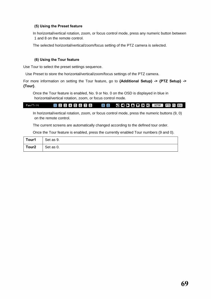
� Once the Tour feature is enabled, No. 9 or No. 0 on the OSD is displayed in blue in horizontal/vertical rotation, zoom, or focus control mode.
� In horizontal/vertical rotation, zoom, or focus control mode, press the numeric buttons (9, 0) on the remote control.
� The current screens are automatically changed according to the defined tour order.
� Once the Tour feature is enabled, press the currently enabled Tour numbers (9 and 0).
Tour1 Set as 9.
Tour2 Set as 0.

70
5. System Setup System setup includes {Main Setup} and {Additional Setup}:
Main Setup Additional Setup Recording setup PTZ setup
Recording schedule Network
System
Storage device
NTP
Advanced
5-1. Main Setup Use {Main Setup} to set the recording and system environment and major features.
5-1-1. Starting the Main Setup
� Press the [Main Setup] button on the remote control or go to the [Main Setup] menu on the real-time monitoring screen.
� The login window is then displayed as shown below:
� Select the login account and input the password using the numeric buttons on the remote control or on the menu. Afterward, select [OK] or press the [Select] button on the remote control.
• (The default password of the local administrator is “00000.”)
• In case the password contains less than five digits, click the [OK] button or press the [Select] button on the remote control.
• Go to the ID selection box and change the ID using the arrow ( ) buttons.

71
� Once the correct password is inputted, the initial screen of {Main Setup} is displayed as shown below:
5-1-2. Recording Setup
Used to set the recording and events
(1) Selecting the recording setup menu mode
{Recording Setup} supports two modes: data mode and channel mode.
A) Selecting the menu method
� Navigate by pressing the [TAB] and arrow ( ) buttons on the remote control. Select
the [Change] button on the data mode menu and channel mode menu and press the [Select]
button. Data mode menu
Channel mode menu

72
Data mode
The user can set the data for Channel Nos. 1 ~ 4 based on the data profile as shown below:
Channel mode
The user can set the data of Channel Nos. 1 ~ 4 based on the four channel groups as shown below:
(2) Saving the recording setting
Set each menu in {Recording Setup} and save the new setting before exiting the menu.
73
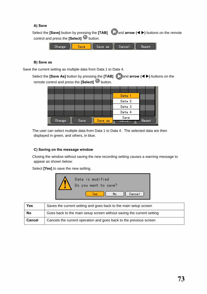
A) Save
� Select the [Save] button by pressing the [TAB] and arrow ( ) buttons on the remote control and press the [Select] button.
B) Save as
Save the current setting as multiple data from Data 1 to Data 4.
� Select the [Save As] button by pressing the [TAB] and arrow ( ) buttons on the remote control and press the [Select] button.
� The user can select multiple data from Data 1 to Data 4. The selected data are then displayed in green, and others, in blue.
C) Saving on the message window
� Closing the window without saving the new recording setting causes a warning message to appear as shown below:
� Select [Yes] to save the new setting.
Yes Saves the current setting and goes back to the main setup screen
No Goes back to the main setup screen without saving the current setting
Cancel Cancels the current operation and goes back to the previous screen
74
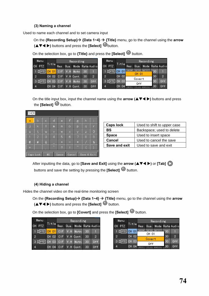
(3) Naming a channel
Used to name each channel and to set camera input
� On the {Recording Setup} {Data 1~4} {Title} menu, go to the channel using the arrow ( ) buttons and press the [Select] button.
� On the selection box, go to {Title} and press the [Select] button.
� On the title input box, input the channel name using the arrow ( ) buttons and press the [Select] button.
Caps lock Used to shift to upper case BS Backspace; used to delete Space Used to insert space Cancel Used to cancel the save Save and exit Used to save and exit
� After inputting the data, go to [Save and Exit] using the arrow ( ) or [Tab]
buttons and save the setting by pressing the [Select] button.
(4) Hiding a channel
Hides the channel video on the real-time monitoring screen
� On the {Recording Setup} {Data 1~4} {Title} menu, go to the channel using the arrow ( ) buttons and press the [Select] button.
� On the selection box, go to [Covert] and press the [Select] button.
75
Screen display based on the recording setup and video input of the camera
VL Stands for Video Loss, which indicates camera video loss or absence of video on that channel
VD Stands for Video Disconnection, which indicates the presence of a video input on the channel but Record and Live are turned off
VC Stands for Video Covert, which means that recording is done but the video is hidden only in Live Mode
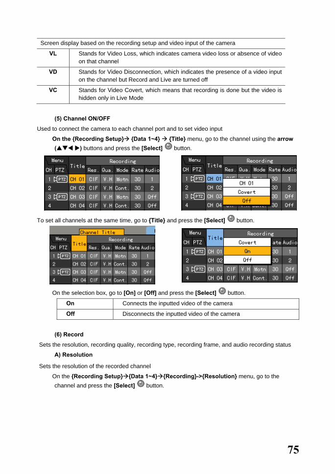
(5) Channel ON/OFF
Used to connect the camera to each channel port and to set video input
� On the {Recording Setup} {Data 1~4} {Title} menu, go to the channel using the arrow ( ) buttons and press the [Select] button.
To set all channels at the same time, go to {Title} and press the [Select] button.
� On the selection box, go to [On] or [Off] and press the [Select] button.
On Connects the inputted video of the camera
Off Disconnects the inputted video of the camera
(6) Record
Sets the resolution, recording quality, recording type, recording frame, and audio recording status
A) Resolution
Sets the resolution of the recorded channel
� On the {Recording Setup} {Data 1~4} {Recording}->{Resolution} menu, go to the channel and press the [Select] button.
76
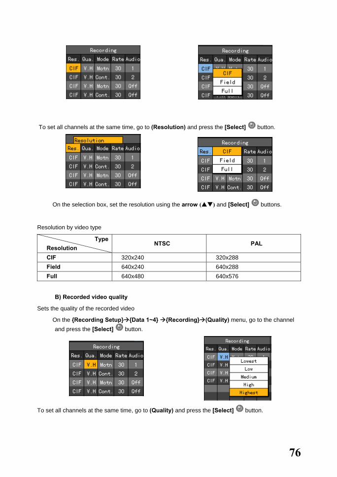
To set all channels at the same time, go to (Resolution) and press the [Select] button.
� On the selection box, set the resolution using the arrow ( ) and [Select] buttons.
Resolution by video type
Type Resolution
NTSC PAL
CIF 320x240 320x288 Field 640x240 640x288 Full 640x480 640x576
B) Recorded video quality
Sets the quality of the recorded video
� On the {Recording Setup} {Data 1~4} {Recording} (Quality) menu, go to the channel and press the [Select] button.
To set all channels at the same time, go to (Quality) and press the [Select] button.

77
� On the selection box, set the recorded video quality using the arrow ( ) and [Select] buttons.
Note ! The size of recorded video files according to recording quality
Recording quality The size of recording video files Lowest Low Middle High Highest
C) Recording type
Recording Type Description
Automatic Sets the event recording speed and normal recording speed separately for automatic recording based on the setting
Continuous Recording done based on the normal frame setting Motion Recording done based on the event frame setting in case motion is
detected Sensor Recording done based on the event frame setting in case of inputted
signal from an external sensor Sound Recording done based on the event frame setting in case sound is
detected
Recording conditions
Recording Type Setting
Continuous {Recording} {Rate} Normal: 1~30 Motion {Event} {Motion}: Partial or Full Sensor {Event} {Sensor}: 1~4 Sound {Event} {Sound}: 1~2
{Recording} {Rate} Event: 1~30
Automatic Enables selecting both normal and event recording frames at the same time
Smaller
Larger

78
� On the {Recording Setup} {Data 1~4} {Recording} {Mode} menu, go to the channel using the arrow ( ) buttons and press the [Select] button.
To set all channels at the same time, go to (Mode) and press the [Select] button.
� On the selection box, set the recording type using the arrow ( ) and [Select] buttons.
D) Recording frame
Recording frames include the normal type and event type.
Normal Sets the recording frame rate for Automatic and Continuous recording
Event Sets the recording frame rate for Automatic, Motion, Sensor, and Sound recording
Note! Maximum recording frame by resolution
Model Resolution
CIF (NTSC/PAL)
(320X240 /320X288)
Field (NTSC/PAL)
(640X240/640X288)
Full (NTSC/PAL)
(640X480/640X576)
Workhorse 120-4 120/100fps 60/50fps 30/25fps
� On the {Recording Setup} {Data 1~4} {Recording} {Rate} menu, go to the channel using the arrow ( ) buttons and press the [Select] button.
� On the selection box, set the recording frame using the arrow ( ) and [Select] buttons.

79
To set all channels at the same time, go to {Rate} and press the [Select] button. E) Audio Recording/Live setting Sets the Recording/Live status for the audio input from an external device that is compatible with the system
� On the {Recording Setup} {Data 1~4} {Recording} {Audio} menu, go to the channel using the arrow ( ) buttons and press the [Select] button.
� On the selection box, set the audio channel using the arrow ( ) and [Select] buttons. (7) Event setup A) Motion Used to detect motion Detection settings include Full, Partial, and OFF. The default setting is OFF. The full video of a certain channel is displayed as shown below (blocks are used to separate the areas where motion is detected). The blue block indicates the areas where motion is detected.
Full
Used to detect motion in each zone
� On the {Recording Setup} {Data 1~4} {Event} (Motion) menu, go to the channel using the arrow ( ) buttons and press the [Select] button.
Motion is not detected. Motion is detected only in the selected zones
Motion is detected in all zones.
80
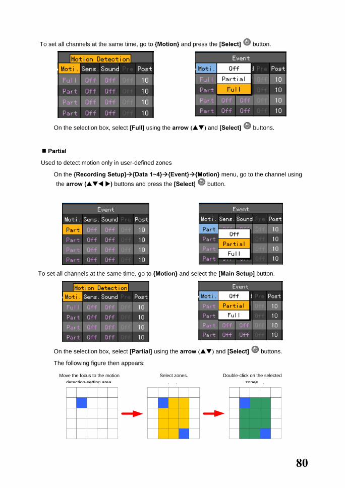
To set all channels at the same time, go to {Motion} and press the [Select] button.
� On the selection box, select [Full] using the arrow ( ) and [Select] buttons.
Partial
Used to detect motion only in user-defined zones
� On the {Recording Setup} {Data 1~4} {Event} {Motion} menu, go to the channel using the arrow ( ) buttons and press the [Select] button.
To set all channels at the same time, go to {Motion} and select the [Main Setup] button.
� On the selection box, select [Partial] using the arrow ( ) and [Select] buttons.
� The following figure then appears:
¸ ð¼Ç ¼ ³Á¤ Á ö¿ ª¿¡ À ̵¿ ÈÄ ´ õº íÅ ¬ Ç ÑÙ .
¸ ð¼Ç ¼ ³Á¤ Å ©± ⦠Á ¤ÇÑ ÈÄÅ ¬ Ç ÑÙ .
¸ ð¼Ç ¿ µ¿ ªÀÌ È ®Á ¤µ Çé , ´ õº íÅ ¬ Ç ÑÙ .
Move the focus to the motion detection-setting area.
Select zones. Double-click on the selected zones.
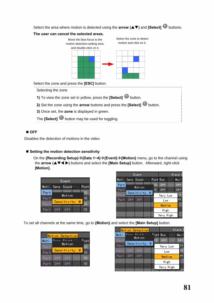
81
� Select the area where motion is detected using the arrow ( ) and [Select] buttons.
� The user can cancel the selected areas. ¸ ð¼Ç ¼ ³Á¤ Á ö¿ ª¿¡ ÆĶ õ»ö
Æ÷Ä ¿½ º¦ À §Ä ¡ÇÑ ÈÄ´ õº íÅ ¬ Ç ÑÙ .
» èÁ ¦ÇÒ ¸ ð¼Ç ¿ µ¿ ªÀ» ¼ ³Á ¤Ç Ï°íÅ ¬ Ç ÑÙ .
� Select the zone and press the [ESC] button.
Selecting the zone
1) To view the zone set in yellow, press the [Select] button.
2) Set the zone using the arrow buttons and press the [Select] button.
3) Once set, the zone is displayed in green.
The [Select] button may be used for toggling.
OFF
Disables the detection of motions in the video
Setting the motion detection sensitivity
� On the {Recording Setup} {Data 1~4} {Event} {Motion} menu, go to the channel using the arrow ( ) buttons and select the [Main Setup] button. Afterward, right-click [Motion].
To set all channels at the same time, go to {Motion} and select the [Main Setup] button.
Move the blue focus to the motion detection-setting area,
and double-click on it.
Select the zone to detect motion and click on it.

82
� On the selection box, set the sensitivity using the arrow ( ) and [Select] buttons.
Setting the sensitivity
Sensitivity levels include Lowest, Low, Middle, High, and Highest, indicating the proportion of pixels to the motions being detected. The higher the grade, the more accurate the detection of motion is.
B) Sensor Defines the settings for detecting input from an external sensor compatible with the system
The user can set up to four external sensors. Once signal input is detected, the video of the
corresponding channel is recorded. Sensor setting
� On the {Recording Setup} {Data 1~4} {Event} {Sensor} menu, go to the channel using the arrow ( ) buttons and press the [Select] button.
To set all channels at the same time, go to {Sensor} and press the [Select] button.
� On the selection box, set the input port number for the external sensor using the arrow ( ) and [Select] buttons.
Sensor type setting

83
� On the {Recording Setup} {Data 1~4} {Event} {Sensor} menu, go to the channel using the arrow ( ) buttons and select the [Main Setup] button. Afterward, right-click [Sensor].
� On the selection box, set the sensor type using the arrow ( ) and [Select] buttons.
Normal Close (NC): Opens in case of incoming signal when closed normally
Normal Open (NO): Closes in case of incoming signal when opened normally
C) Sound
Defines the settings for detecting audio input from an external device compatible with the system
The user can set the audio input for two external devices compatible with the system. Once audio
input is detected, the video of the corresponding channel is recorded. Each channel can detect audio
from up to two devices.
� On the {Recording Setup} {Data 1~4} {Event} {Sound} menu, go to the channel using the arrow ( ) buttons and press the [Select] button.
To set all channels at the same time, go to {Sound} and press the [Select] button.

84
� On the selection box, select the audio channel using the arrow ( ) and [Select] buttons.
� The user can detect audio input from multiple devices by defining the settings as follows:
� To adjust the audio sensitivity of each channel, go to {Sound} and select the [Main Setup] button. Afterward, right-click [Sound].
� On the selection box, set the audio channel using the arrow ( ) and [Select] buttons.
D) Post (This DVR does not support Prerecord time)
Sets the recording time upon the occurrence of an event
The unit is in seconds. Whenever an event is detected, recording is done for the defined time.
� On the {Recording Setup} {Data 1~4} {Event} {Post} menu, go to the channel using the arrow ( ) buttons and press the [Select] button.
Occurrence of an event
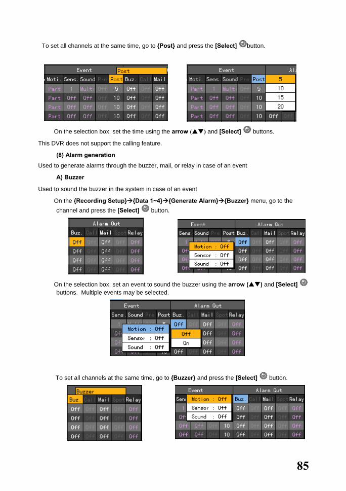
85
To set all channels at the same time, go to {Post} and press the [Select] button.
� On the selection box, set the time using the arrow ( ) and [Select] buttons.
This DVR does not support the calling feature.
(8) Alarm generation
Used to generate alarms through the buzzer, mail, or relay in case of an event
A) Buzzer
Used to sound the buzzer in the system in case of an event
� On the {Recording Setup} {Data 1~4} {Generate Alarm} {Buzzer} menu, go to the channel and press the [Select] button.
� On the selection box, set an event to sound the buzzer using the arrow ( ) and [Select] buttons. Multiple events may be selected.
To set all channels at the same time, go to {Buzzer} and press the [Select] button.
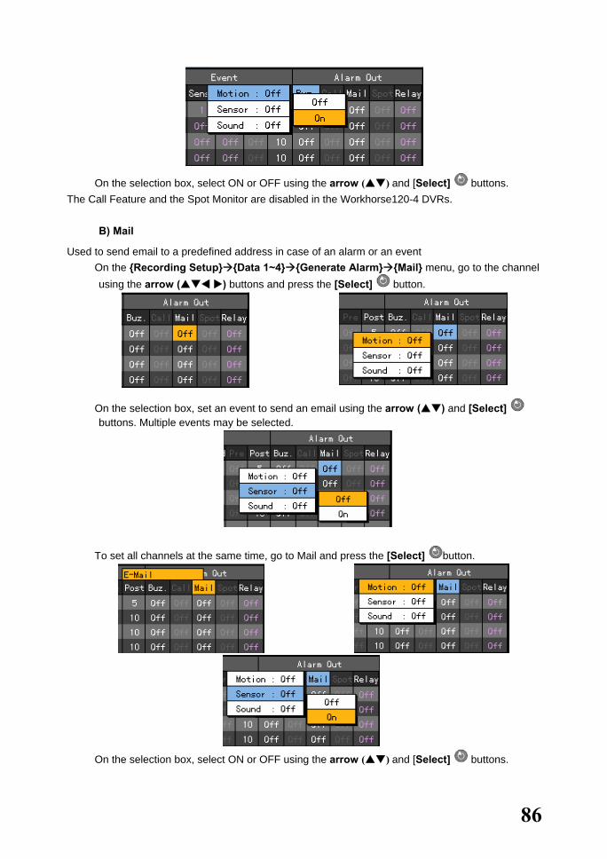
86
� On the selection box, select ON or OFF using the arrow ( ) and [Select] buttons. The Call Feature and the Spot Monitor are disabled in the Workhorse120-4 DVRs.
B) Mail
Used to send email to a predefined address in case of an alarm or an event � On the {Recording Setup} {Data 1~4} {Generate Alarm} {Mail} menu, go to the channel
using the arrow ( ) buttons and press the [Select] button.
� On the selection box, set an event to send an email using the arrow ( ) and [Select] buttons. Multiple events may be selected.
To set all channels at the same time, go to Mail and press the [Select] button.
� On the selection box, select ON or OFF using the arrow ( ) and [Select] buttons.
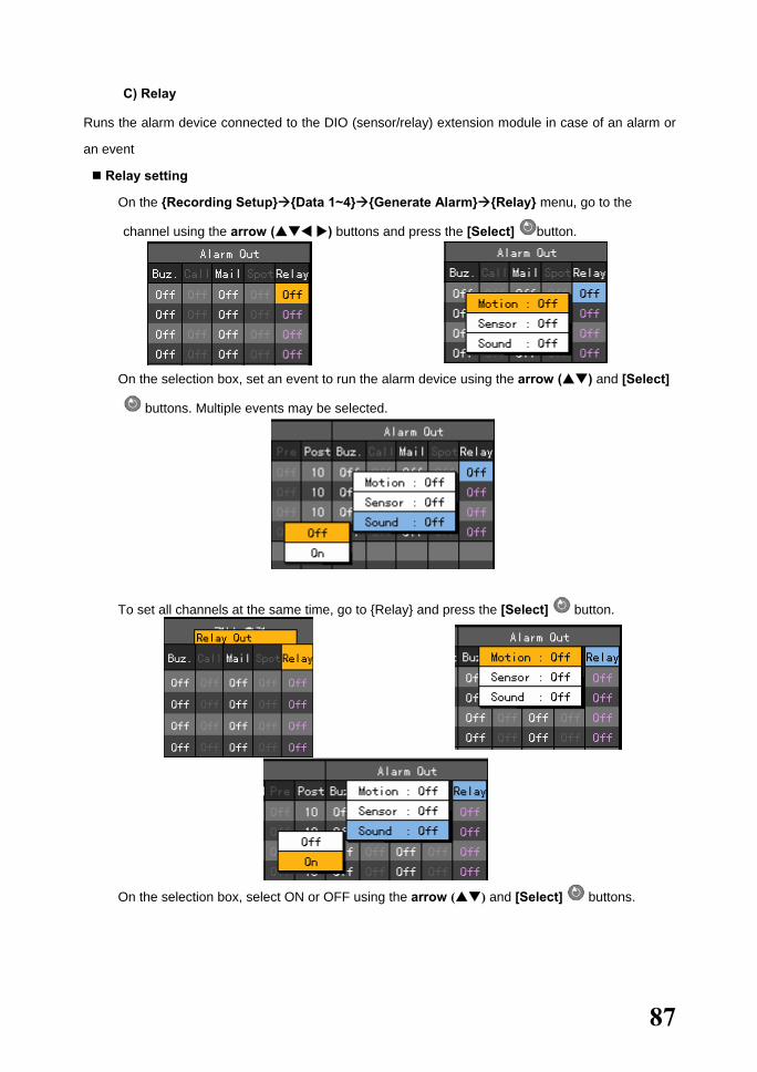
87
C) Relay
Runs the alarm device connected to the DIO (sensor/relay) extension module in case of an alarm or
an event
Relay setting
� On the {Recording Setup} {Data 1~4} {Generate Alarm} {Relay} menu, go to the
channel using the arrow ( ) buttons and press the [Select] button.
� On the selection box, set an event to run the alarm device using the arrow ( ) and [Select]
buttons. Multiple events may be selected.
To set all channels at the same time, go to {Relay} and press the [Select] button.
� On the selection box, select ON or OFF using the arrow ( ) and [Select] buttons.

88
Relay type setting
� On the {Recording Setup} {Data 1~4} {Generate Alarm} {Relay} menu, go to the
channel using the arrow ( ) buttons and select the [Main Setup] button. Afterward,
right-click [Relay].

89
5-1-3. Recording Schedule
Use {Recording Schedule} to save the system configuration as data from Data 1 to Data 4 and to
perform recording based on the system configuration for each day/time zone.
To apply the new setting, save the new setting.
[Holiday]
Sets holidays
[Save] Saves the setting
[Cancel] Exits without saving the setting
[Reset] Initializes the setting
(1) Selecting the Recording Schedule menu
� In {Main Setup} mode, go to {Recording Schedule} and click the [Select] button.
(2) Recording schedule setting A) Setting by row
� On the {Recording Schedule} menu, go to the date and time using the arrow ( ) or numeric buttons on the remote control.
Input numbers that are less than 10 in two digits using the numeric buttons, e.g., 01 for 1 and 02 for 2. At this time, the time line is highlighted.

90
� Select the time to set the data.
a) To set the selected time only, press the [Main Setup] button or right-click the
corresponding button on the menu.
b) To set all rows after the selected time, press the [Select] button or double-click the
corresponding button on the menu.
� On the selection box, go to the data using the arrow ( ) buttons and press the [Select]
button.
� Data are set based on the buttons pressed during time selection.
a) Clicking the [Main Setup] button causes the data to be set only for the selected time.

91
b) Clicking the [Select] button causes the data to be set for all times after the selected time.
B) Setting by column
� On the schedule menu, go to the row using the arrow ( ) or numeric buttons on the remote control.
Input numbers that are less than 10 in two digits using the numeric buttons, e.g., 01 for 1 and 02 for 2.
� Select the time to set the data.
a) To set only one column of the selected time, press the [Main Setup] button on the remote control or right-click the corresponding button on the menu.
b) To set all rows and columns after the selected time at the same time, press the [Select] button or double-click the corresponding button on the menu.

92
� On the selection box, go to the data using the arrow ( ) buttons and press the [Select] button.
� Data are set based on the buttons pressed during time selection.
a) Pressing the [Main Setup] button causes the data to be set only for the column with the selected time.
b) Clicking the [Select] button causes the data to be set for all rows and columns after the selected time.
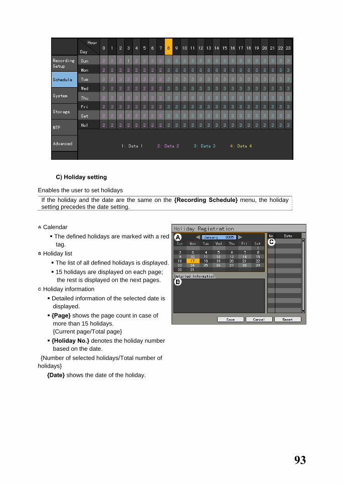
93
C) Holiday setting
Enables the user to set holidays If the holiday and the date are the same on the {Recording Schedule} menu, the holiday setting precedes the date setting.
○A Calendar The defined holidays are marked with a red tag.
○B Holiday list The list of all defined holidays is displayed. 15 holidays are displayed on each page; the rest is displayed on the next pages.
○C Holiday information Detailed information of the selected date is displayed.
{Page} shows the page count in case of more than 15 holidays. {Current page/Total page}
{Holiday No.} denotes the holiday number based on the date.
{Number of selected holidays/Total number of holidays}
{Date} shows the date of the holiday.

94
� On the {Recording Schedule} menu, go to {Holiday} at the bottom using the [Tab] and
arrow ( ) buttons and press the [Select] button.
� On the {Add Holiday} window, go to the date using the arrow ( ) and [Select]
buttons and press the [Select] button.
� After setting the holiday, press the [ESC] button followed by the [Save] button at the bottom of
the menu and press the [Select] button. [Save] Saves the setting [Cancel] Exits without saving the setting [Reset] Resets the setting
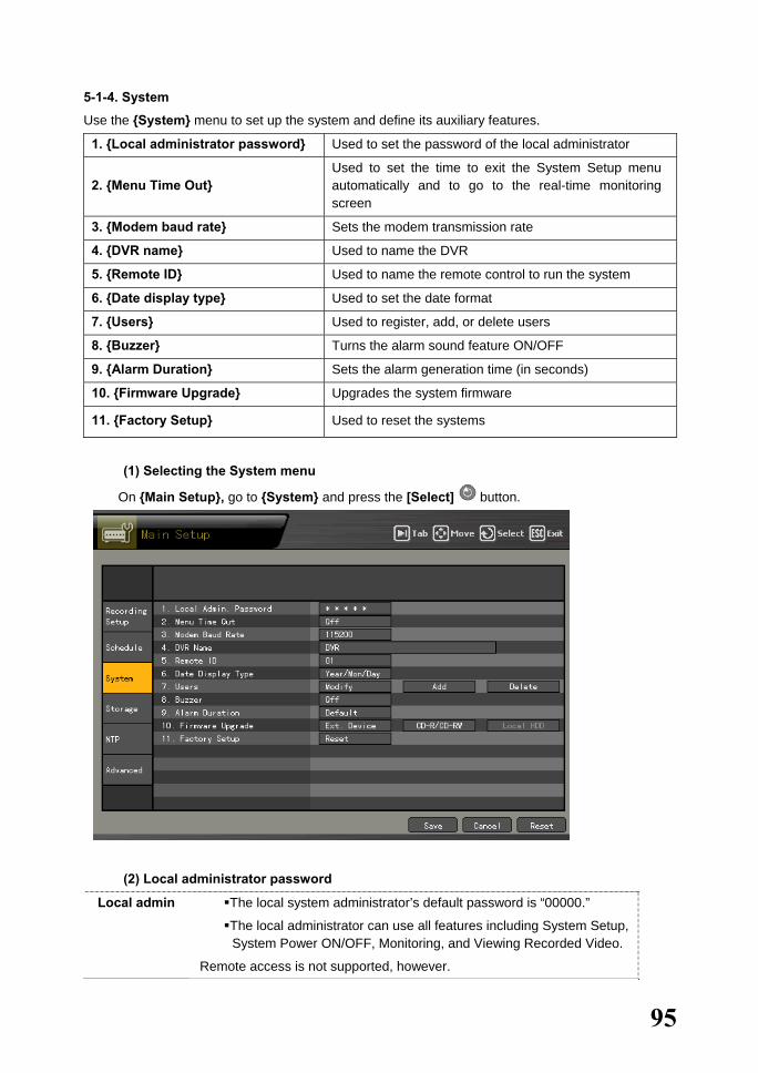
95
5-1-4. System
Use the {System} menu to set up the system and define its auxiliary features.
1. {Local administrator password} Used to set the password of the local administrator
2. {Menu Time Out} Used to set the time to exit the System Setup menu automatically and to go to the real-time monitoring screen
3. {Modem baud rate} Sets the modem transmission rate
4. {DVR name} Used to name the DVR
5. {Remote ID} Used to name the remote control to run the system
6. {Date display type} Used to set the date format
7. {Users} Used to register, add, or delete users
8. {Buzzer} Turns the alarm sound feature ON/OFF
9. {Alarm Duration} Sets the alarm generation time (in seconds)
10. {Firmware Upgrade} Upgrades the system firmware
11. {Factory Setup} Used to reset the systems
(1) Selecting the System menu
� On {Main Setup}, go to {System} and press the [Select] button.
(2) Local administrator password
Local admin The local system administrator’s default password is “00000.”
The local administrator can use all features including System Setup, System Power ON/OFF, Monitoring, and Viewing Recorded Video.
Remote access is not supported, however.

96
� On the {System} menu, go to the {1. Local Administrator Password} input field using the arrow ( ) buttons and press the [Select] button.
� On the password input field, enter the password using the numeric buttons on the remote control or the arrow ( ) and [Select] buttons. The password may contain up to five digits.
BS Backspace
Cancel Used to cancel the save
Save and exit Used to save and exit
� After inputting the data, go to [Save and Exit] using the [Tab] or arrow ( ) buttons and
press the [Select] button.
(3) Menu Time Out
If no input is made on the System Setup menu using the front buttons, remote control, or mouse, the
system automatically shifts to real-time monitoring mode. � On the {System} menu, go to {2. Menu Time Ou } using the arrow ( ) buttons and press
the [Select] button.
� On the selection box, select the time to be set using the arrow ( ) and [Select] buttons.
OFF The Automatic Exit menu is not used.
The user can exit the menu by pressing the [ESC] button on the System menu.
10/20/30 seconds If no input is made using the touch pad, remote control, or mouse, the system shifts to real-time monitoring mode.
User setting Enables the user to input the time
The time is between 5 and 99 seconds.
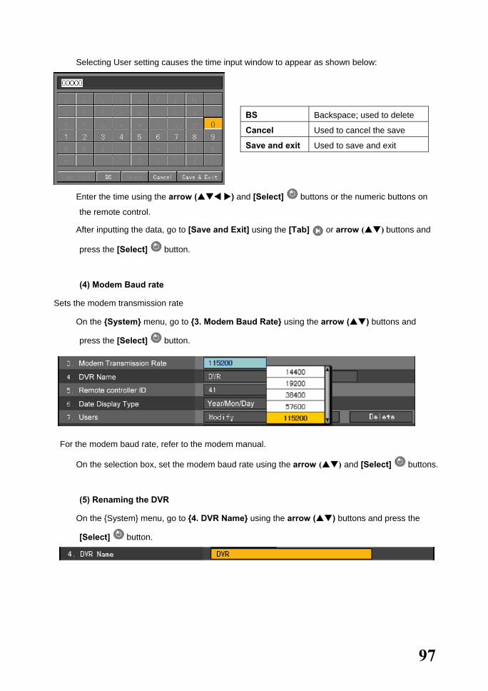
97
� Selecting User setting causes the time input window to appear as shown below:
BS Backspace; used to delete
Cancel Used to cancel the save
Save and exit Used to save and exit
� Enter the time using the arrow ( ) and [Select] buttons or the numeric buttons on
the remote control.
� After inputting the data, go to [Save and Exit] using the [Tab] or arrow ( ) buttons and
press the [Select] button.
(4) Modem Baud rate
Sets the modem transmission rate
� On the {System} menu, go to {3. Modem Baud Rate} using the arrow ( ) buttons and
press the [Select] button.
For the modem baud rate, refer to the modem manual.
� On the selection box, set the modem baud rate using the arrow ( ) and [Select] buttons.
(5) Renaming the DVR
� On the {System} menu, go to {4. DVR Name} using the arrow ( ) buttons and press the
[Select] button.
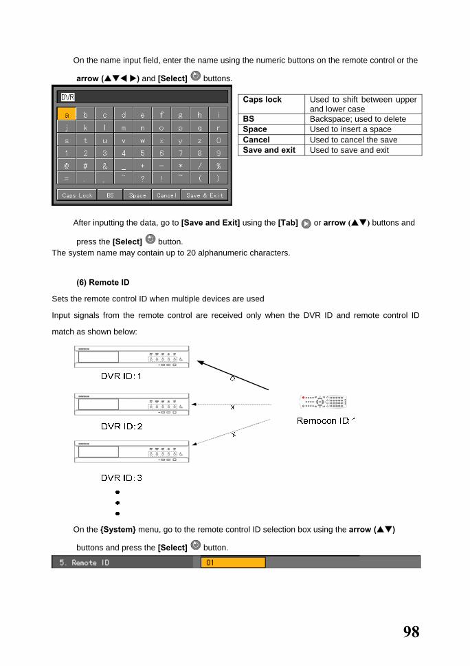
98
� On the name input field, enter the name using the numeric buttons on the remote control or the
arrow ( ) and [Select] buttons.
Caps lock Used to shift between upper
and lower case BS Backspace; used to delete Space Used to insert a space Cancel Used to cancel the save Save and exit Used to save and exit
� After inputting the data, go to [Save and Exit] using the [Tab] or arrow ( ) buttons and
press the [Select] button. The system name may contain up to 20 alphanumeric characters.
(6) Remote ID
Sets the remote control ID when multiple devices are used
Input signals from the remote control are received only when the DVR ID and remote control ID
match as shown below:
� On the {System} menu, go to the remote control ID selection box using the arrow ( )
buttons and press the [Select] button.
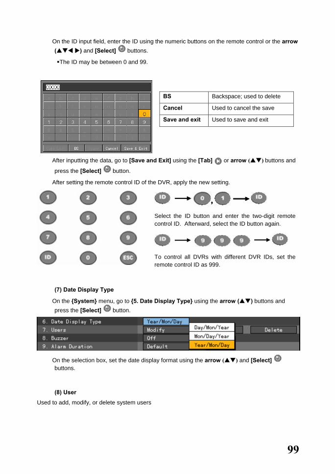
99
� On the ID input field, enter the ID using the numeric buttons on the remote control or the arrow ( ) and [Select] buttons.
The ID may be between 0 and 99.
BS Backspace; used to delete
Cancel Used to cancel the save
Save and exit Used to save and exit
� After inputting the data, go to [Save and Exit] using the [Tab] or arrow ( ) buttons and
press the [Select] button.
� After setting the remote control ID of the DVR, apply the new setting.
Select the ID button and enter the two-digit remote control ID. Afterward, select the ID button again.
To control all DVRs with different DVR IDs, set the remote control ID as 999.
(7) Date Display Type
� On the {System} menu, go to {5. Date Display Type} using the arrow ( ) buttons and press the [Select] button.
� On the selection box, set the date display format using the arrow ( ) and [Select] buttons.
(8) User
Used to add, modify, or delete system users

100
System authority
Network live Viewing screen in real time
Network play Viewing recorded screen
Download network file Network access, File download
Main setup Data, Schedule, System setup
Additional setup PTZ camera, Network setup
Network PTZ control PTZ camera control
Network backup Backup feature
Remote upgrade Remote upgrade
A) Modifying user information
� On the {System} menu, go to {6. User} ->{Modify} using the arrow ( ) buttons and press the [Select] button.
� On the selection box, select a user using the arrow ( ) and [Select] buttons.
� On the user authority setting window, set the user authorities using the arrow ( ) and
[Select] buttons.
Gives the user the authority to use the feature
Prohibits the user from using the feature
� After inputting the data, go to [Modify] using the [Tab] or arrow ( ) buttons and press
the [Select] button.
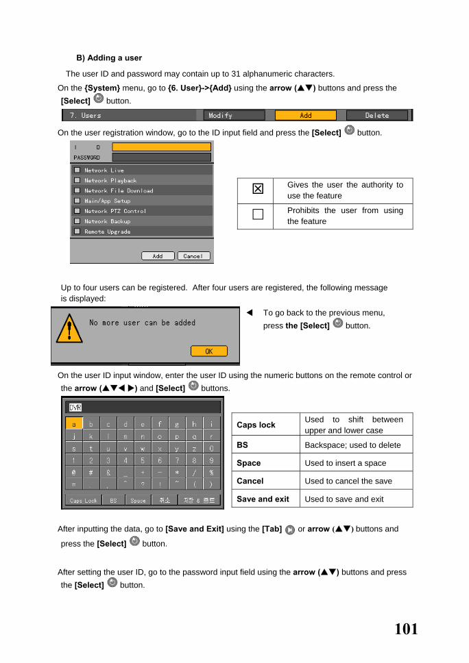
101
B) Adding a user
The user ID and password may contain up to 31 alphanumeric characters.
� On the {System} menu, go to {6. User}->{Add} using the arrow ( ) buttons and press the [Select] button.
� On the user registration window, go to the ID input field and press the [Select] button.
Gives the user the authority to use the feature
Prohibits the user from using the feature
Up to four users can be registered. After four users are registered, the following message is displayed:
To go back to the previous menu, press the [Select] button.
� On the user ID input window, enter the user ID using the numeric buttons on the remote control or the arrow ( ) and [Select] buttons.
Caps lock Used to shift between upper and lower case
BS Backspace; used to delete
Space Used to insert a space
Cancel Used to cancel the save
Save and exit Used to save and exit
� After inputting the data, go to [Save and Exit] using the [Tab] or arrow ( ) buttons and
press the [Select] button.
� After setting the user ID, go to the password input field using the arrow ( ) buttons and press the [Select] button.

102
Gives the user the authority to use the feature Prohibits the user from using the feature
� On the password input window, enter the password using the numeric buttons on the remote
control or the arrow ( ) and [Select] buttons.
The password may contain up to 31 digits.
BS Backspace; used to delete Cancel Used to cancel the save Save and exit Used to save and exit
� After inputting the data, go to [Save and Exit] using the [Tab] or arrow ( ) buttons and
press the [Select] button.
� After setting the user ID and password, set the user authorities using the arrow ( ) and
[Select] buttons.
Gives the user the authority to use the feature Prohibits the user from using the feature
� After defining the authority to use the feature, go to [Add] using the [Tab] or arrow ( )
buttons and press the [Select] button.
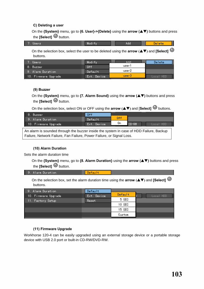
103
C) Deleting a user
� On the {System} menu, go to {6. User}->{Delete} using the arrow ( ) buttons and press the [Select] button.
� On the selection box, select the user to be deleted using the arrow ( ) and [Select] buttons.
(9) Buzzer
� On the {System} menu, go to {7. Alarm Sound} using the arrow ( ) buttons and press the [Select] button.
� On the selection box, select ON or OFF using the arrow ( ) and [Select] buttons.
An alarm is sounded through the buzzer inside the system in case of HDD Failure, Backup Failure, Network Failure, Fan Failure, Power Failure, or Signal Loss.
(10) Alarm Duration
Sets the alarm duration time
� On the {System} menu, go to {8. Alarm Duration} using the arrow ( ) buttons and press the [Select] button.
� On the selection box, set the alarm duration time using the arrow ( ) and [Select] buttons.
(11) Firmware Upgrade
Workhorse 120-4 can be easily upgraded using an external storage device or a portable storage device with USB 2.0 port or built-in CD-RW/DVD-RW.

104
� Find the upgrade file and copy it to the highest folder in the external storage device or portable storage device.
1) 2) 3)
When copying an upgrade file from the PC, connect the USB device to the PC first. If the USB device is disconnected from the port while the upgrade file is being copied, the DVR system may not automatically recognize the file. Upgrading cannot proceed if no HDD is installed.
� Connect the storage device containing an upgrade file to the USB port on the DVR.
� On the {System} menu, go to {10. Firmware Upgrade} using the arrow ( ) buttons.
� Press the [Select] button.
The upgrade information window then appears within 15 seconds as shown below:
Information

105
� After checking the information, select the [Yes] button. Upgrading then proceeds in the following order (selecting the [No] button causes the system to shift to {System} mode):
Once it starts, upgrading cannot be canceled.
� After upgrading is completed, the system restarts.
� The system automatically starts, and upgrading is completed.
� Select {Status} -> {Product Information} -> {3. Software Version}.
(12) Factory Setup
� On the {System} menu, go to {11. Factory Setup} using the arrow ( ) buttons and press the [Select] button.
� To reset, click the [Yes] button.
All settings except the network configuration are reset.
Used to select the factory setting
Information Information
Information Information
Current Version New Version
Current Version New Version
Current Version New Version
Current Version New Version
Upgrade Contents
Yes No
Upgrade Contents
Yes No
Upgrade Contents
Yes No
Upgrade Contents
Yes No

106
(13) Saving the system configuration
After changing the system configuration on the {System} menu, save the new configuration before
exiting the menu. � After completing the system configuration, go to [Save] by selecting the [Tab] button and
press the [Select] button.
[Save] Saves the new configuration
[Cancel] Exits without saving the new configuration
[Reset] Resets the configuration

107
5-1-5.Storage Device
(1) Selecting the Storage Device menu
� Select {Main Setup} and {Storage Device}.
A) Local
(1) Selecting the Local menu
� On the {Storage Device} menu, go to the {Local} tab using the arrow ( ) and [Select] buttons .
To apply the new setting defined in the [Storage Device] menu, save the new setting.
[Update]
Used to read local storage device management information again
[Save] Saves the setting
[Cancel] Exits without saving the setting
[Reset] Resets the setting
(2) Maximum Archiving days
Limits the recording days
� On the {Storage Device} menu, go to {1. Maximum Archiving Days} using the arrow ( ) buttons and press the [Select] button.
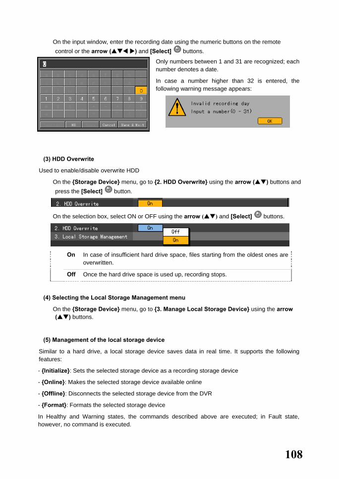
108
� On the input window, enter the recording date using the numeric buttons on the remote control or the arrow ( ) and [Select] buttons.
Only numbers between 1 and 31 are recognized; each number denotes a date.
In case a number higher than 32 is entered, the following warning message appears:
(3) HDD Overwrite
Used to enable/disable overwrite HDD
� On the {Storage Device} menu, go to {2. HDD Overwrite} using the arrow ( ) buttons and press the [Select] button.
� On the selection box, select ON or OFF using the arrow ( ) and [Select] buttons.
On In case of insufficient hard drive space, files starting from the oldest ones are overwritten.
Off Once the hard drive space is used up, recording stops.
(4) Selecting the Local Storage Management menu
� On the {Storage Device} menu, go to {3. Manage Local Storage Device} using the arrow ( ) buttons.
(5) Management of the local storage device
Similar to a hard drive, a local storage device saves data in real time. It supports the following features:
- {Initialize}: Sets the selected storage device as a recording storage device
- {Online}: Makes the selected storage device available online
- {Offline}: Disconnects the selected storage device from the DVR
- {Format}: Formats the selected storage device
In Healthy and Warning states, the commands described above are executed; in Fault state, however, no command is executed.

109
(6) Configuration of the local storage device
� {Model}: Storage device model
� {Serial}: Serial number of the storage device
� {Location}: Physical location of the storage device
� {Capacity (F/T)}: Capacity of the storage device (T: Total; F: Free)
� {Status (HW/SW)}: Status of the storage device (HW/SW; SW: Software; HW: Hardware)
Three software status types
- Active: Connected to the DVR; the storage device is currently recording
- Online: Connected to the DVR, but the storage device is not recording
- Offline: Not connected to the DVR
Three hardware status types
- Healthy: Connected to the DVR; the storage device is recording normally
- Warning: Connected to the DVR, but an error has occurred; in this state, recording may
fail (for more information, see the warning below)
- Fault: Not connected to the DVR, possible hardware damage; in this state, the storage
device cannot operate
1. Fault state: The storage device is damaged and unable to function properly. Fault state is not related to DVR troubles. The DVR detects errors in the storage device and stops recording. 2. Warning state: The storage device has a physical error that can be corrected
by the storage device or DVR. Failure to repair the error may damage the storage device (and cause it to shift to fault state). In this case, backing up the data in the corresponding storage device and replacing the device with a normal one is strongly recommended.
3. If the active storage device is in warning or fault state, an alarm message is displayed on the upper left hand corner of the screen. After the user views the alarm message on the {Log} menu, however, the alarm message is deleted.

110
(7) After adding a local storage device
� Open the DVR body, connect the drive to the IDE cable, and connect the power cord.
� Supply power to the DVR and boot the system.
� Select the [Main Setup] button and enter the password. On the {Storage Device} menu, go
to {Storage Device}->{Local} using the arrow ( ) buttons.
� The following window is then displayed together with information on the newly installed drive :
� Select a model using the arrow ( ) and [Select] buttons as shown below and reset the
selected model:
� Selecting a menu using the [Select] button causes a confirmation message to appear as
shown below:
� Select [Yes]. Drive is in offline state are then displayed as shown below:

111
� To make a model available online, select the desired model using the [Select] button followed by the Online menu.
� Selecting a menu using the [Select] button causes a confirmation message to appear as shown below:
� Select [Yes]. Drive s in online state are then displayed as shown below:
(8) Operation of the local storage device
� The user can select any valid storage device using the arrow ( ) buttons.
� Select a storage device using the [Select] button. A popup menu is then displayed as shown below:
� Select and execute the corresponding menu using the arrow ( ) and [Select] buttons.
� The system confirms the execution of every command as shown below:
� Click [OK] to execute the corresponding command.

112
B) NAS backup
(1) Selecting the NAS Backup menu
� Select {Main Setup}, {Storage Device} -> {NAS Backup}.
(2) NAS Use
� On the {Storage} menu, go to {NAS Backup} -> {1. Use NAS} using the arrow ( ) buttons and press the [Select] button.
� On the selection box, select ON or OFF using the arrow ( ) and [Select] buttons.
� Selecting ON or Test causes a test to run as shown below:
(3) ID
� Go to the {2. ID} menu using the arrow ( ) buttons and press the [Select] button.
� On the input window, enter the ID using the arrow ( ) and [Select] buttons.

113
Caps lock Used to shift between upper and lower case
BS Backspace; used to delete
Space Used to insert space
Cancel Used to cancel the save
Save and exit Used to save and exit
� After inputting the data, go to [Save and Exit] using the arrow ( ) or [Tab] buttons and
save the setting by pressing the [Select] button.
(4) Password
� Go to the {3. Password} menu using the arrow ( ) buttons and press the [Select]
button.
� On the input window, enter the password using the arrow ( ) and [Select] buttons.
Caps lock Used to shift between upper and lower case
BS Backspace; used to delete
Space Used to insert space
Cancel Used to cancel the save
Save and exit Used to save and exit
� After inputting the data, go to [Save and Exit] using the arrow ( ) or [Tab] buttons
and save the setting by pressing the [Select] button.
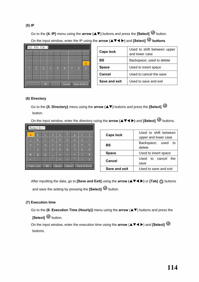
114
(5) IP
� Go to the {4. IP} menu using the arrow ( ) buttons and press the [Select] button.
� On the input window, enter the IP using the arrow ( ) and [Select] buttons.
(6) Directory
� Go to the {5. Directory} menu using the arrow ( ) buttons and press the [Select]
button.
� On the input window, enter the directory using the arrow ( ) and [Select] buttons.
Caps lock Used to shift between upper and lower case
BS Backspace; used to delete
Space Used to insert space
Cancel Used to cancel the save
Save and exit Used to save and exit
� After inputting the data, go to [Save and Exit] using the arrow ( ) or [Tab] buttons
and save the setting by pressing the [Select] button.
(7) Execution time
� Go to the {6. Execution Time (Hourly)} menu using the arrow ( ) buttons and press the
[Select] button.
� On the input window, enter the execution time using the arrow ( ) and [Select]
buttons.
Caps lock Used to shift between upper and lower case
BS Backspace; used to delete
Space Used to insert space
Cancel Used to cancel the save
Save and exit Used to save and exit
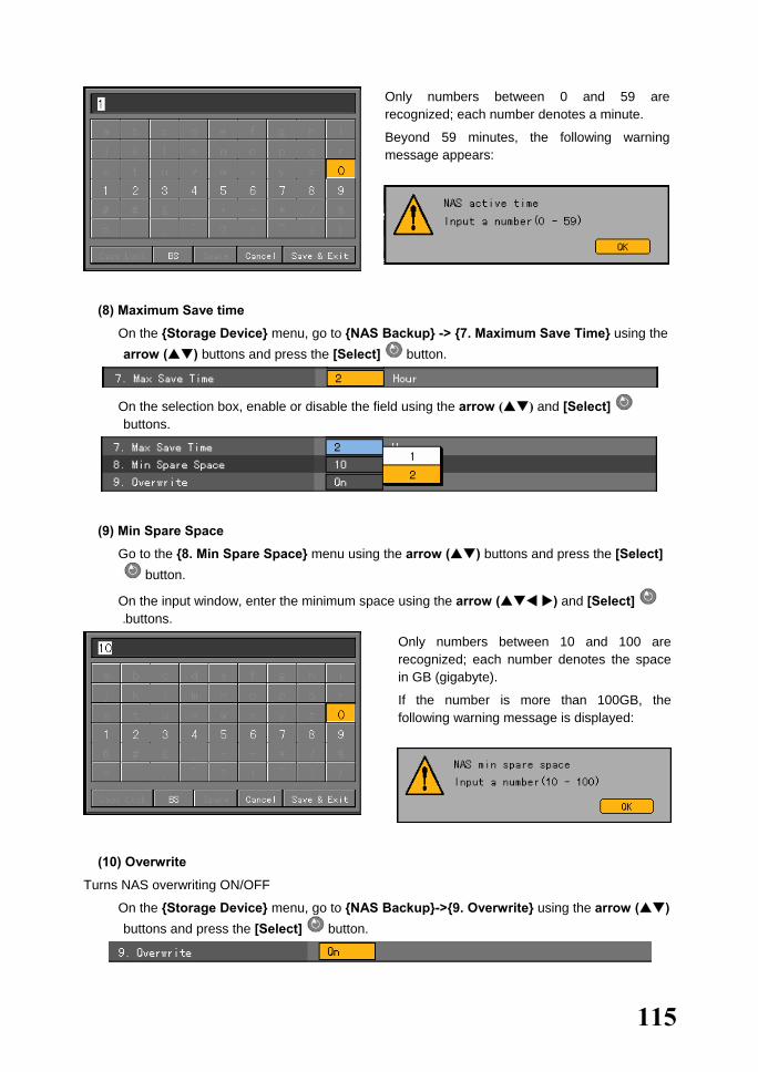
115
Only numbers between 0 and 59 are recognized; each number denotes a minute.
Beyond 59 minutes, the following warning message appears:
(8) Maximum Save time
� On the {Storage Device} menu, go to {NAS Backup} -> {7. Maximum Save Time} using the arrow ( ) buttons and press the [Select] button.
� On the selection box, enable or disable the field using the arrow ( ) and [Select] buttons.
(9) Min Spare Space
� Go to the {8. Min Spare Space} menu using the arrow ( ) buttons and press the [Select] button.
� On the input window, enter the minimum space using the arrow ( ) and [Select] buttons.
Only numbers between 10 and 100 are recognized; each number denotes the space in GB (gigabyte).
If the number is more than 100GB, the following warning message is displayed:
(10) Overwrite
Turns NAS overwriting ON/OFF
� On the {Storage Device} menu, go to {NAS Backup}->{9. Overwrite} using the arrow ( ) buttons and press the [Select] button.

116
� On the selection box, select ON or OFF using the arrow ( ) and [Select] buttons.
117
5-1-6. NTP
Protocol for synchronizing the time between devices connected through the network
Description of features
1. Time synchronization
1) Synchronization with the NTP server
Time is synchronized with the NTP server by the hour.
A. Automatic setting
Connection with the server nearest to the user-defined zone is attempted or the next nearest server if connection fails.
B. User setting
The user sets the URL or IP of the NTP server. If connection is not established, a message is sent to the user, and the corresponding logs, saved.
If synchronization with the NTP server fails, synchronization with the RTC ensues.
2) Synchronization with the DVR Time Server
The DTS server runs in Workhorse 120-4; time is synchronized by the hour. Workhorse 120-4 DTS clients referring to the DTS synchronize the time of the DVR system.
Any change in the DTS time or zone is reflected on the Workhorse 120-4 of the network (synchronization signals are broadcast without passing through the router or gateway; the DVR time server does not support automatic connection).
2. Daylight saving time (DST) setting
The DST is automatically processed depending on the zone, i.e., whether the NTP server or the DST server is used as a reference.
3. User time setting
The user can set the time.
For NTP client setting, however, the user can only read the time but not change it.
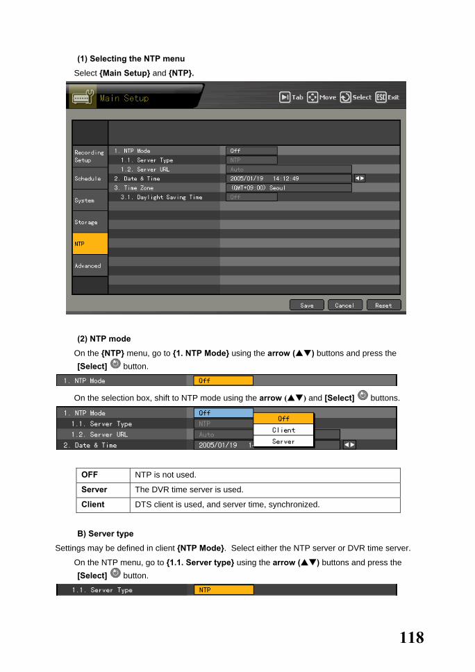
118
(1) Selecting the NTP menu
� Select {Main Setup} and {NTP}.
(2) NTP mode
� On the {NTP} menu, go to {1. NTP Mode} using the arrow ( ) buttons and press the [Select] button.
� On the selection box, shift to NTP mode using the arrow ( ) and [Select] buttons.
OFF NTP is not used.
Server The DVR time server is used.
Client DTS client is used, and server time, synchronized.
B) Server type
Settings may be defined in client {NTP Mode}. Select either the NTP server or DVR time server.
� On the NTP menu, go to {1.1. Server type} using the arrow ( ) buttons and press the [Select] button.

119
� On the selection box, set the audio channel using the arrow ( ) and [Select] buttons.
C) Server URL
Settings may be defined only in client NTP mode. Set the address of the NTP server or DVR time server.
� On the {NTP} menu, go to {1.2. Server URL} using the arrow ( ) buttons and press the [Select] button.
� On the selection box, set the server URL using the arrow ( ) and [Select] buttons.
� The user can input the IP only when the server type is DVR. For the NTP server, Automatic, IP,
or URL should be selected.
Automatic
Attempts to connect to the server nearest to the user-defined zone or the next nearest server if connection fails
IP
On the numeric data input window, enter the IP of the server to synchronize the time.
URL
On the text input window, enter the URL of the server to synchronize the time.
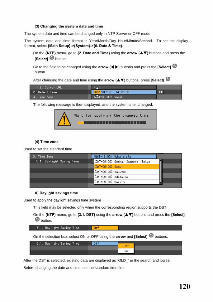
120
(3) Changing the system date and time
The system date and time can be changed only in NTP Server or OFF mode.
The system date and time format is Year/Month/Day Hour/Minute/Second. To set the display format, select {Main Setup}->{System}->{6. Date & Time}.
� On the {NTP} menu, go to {2. Date and Time} using the arrow ( ) buttons and press the [Select] button.
� Go to the field to be changed using the arrow ( ) buttons and press the [Select] button.
� After changing the date and time using the arrow ( ) buttons, press [Select] .
� The following message is then displayed, and the system time, changed:
(4) Time zone
Used to set the standard time
A) Daylight savings time
Used to apply the daylight savings time system
� This field may be selected only when the corresponding region supports the DST.
� On the {NTP} menu, go to {3.1. DST} using the arrow ( ) buttons and press the [Select] button.
� On the selection box, select ON or OFF using the arrow and [Select] buttons.
After the DST is selected, existing data are displayed as “OLD_” in the search and log list.
Before changing the date and time, set the standard time first.
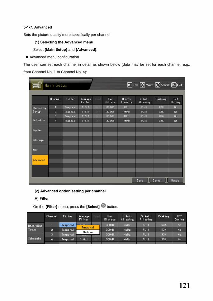
121
5-1-7. Advanced
Sets the picture quality more specifically per channel
(1) Selecting the Advanced menu
� Select {Main Setup} and {Advanced}.
Advanced menu configuration
The user can set each channel in detail as shown below (data may be set for each channel, e.g.,
from Channel No. 1 to Channel No. 4):
(2) Advanced option setting per channel
A) Filter
� On the {Filter} menu, press the [Select] button.
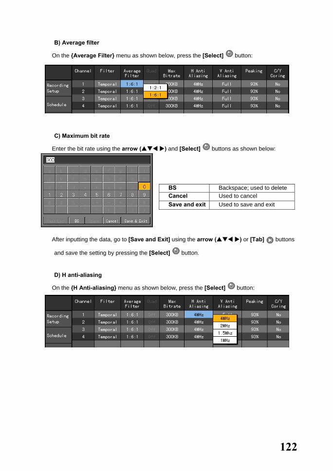
122
B) Average filter
� On the {Average Filter} menu as shown below, press the [Select] button:
C) Maximum bit rate
� Enter the bit rate using the arrow ( ) and [Select] buttons as shown below:
BS Backspace; used to delete Cancel Used to cancel Save and exit Used to save and exit
� After inputting the data, go to [Save and Exit] using the arrow ( ) or [Tab] buttons
and save the setting by pressing the [Select] button.
D) H anti-aliasing
� On the {H Anti-aliasing} menu as shown below, press the [Select] button:

123
E) V anti-aliasing
� On the {V Anti-aliasing} menu as shown below, press the [Select] button:
F) Peaking
� On the {Peaking} menu as shown below, press the [Select] button:
G) C/Y cording
� On the {C/Y Cording} menu as shown below, press the [Select] button:

124
(3) Description of advanced options
Menu Description
{Filter} This is used to filter the images. Either Median Filter or Temporal Filter may be selected. If there is lots of noise in the still image, select Median Filter; if there is lots of noise in the moving image, however, Temporal Filter is recommended. Since the DVR handles moving images, Temporal Filter is recommended.
{Average filter} Either 1:6:1 or 1:2:1 may be selected. For 1:6:1 (which is also the default setting), however, the file size is high but the filtering degree is low; this means that the resulting image is close to the original image.
{Quad} -
{Maximum bit rate} This refers to the maximum size unit for the streaming of moving images.
{H anti-aliasing} This is used to set the horizontal anti-aliasing. In most cases, 4MHz is closest to the actual video.
{V anti-aliasing} This is used to set the vertical anti-aliasing. In most cases, the [All] option is closest to the actual video.
{Peaking} Peaking emphasizes the edge of the Y elements. The user can select No, 31%, 62%, or 93%. At 93% (which is also the default setting), however, the edges are emphasized the most.
{C/Y cording} Cording is used to keep the edges sharp among the Y elements of the image. The user can select No, +/-1, +/-2, or +/-4. To get the softest images, however, +/-4 is recommended; the default setting is No. The user can get the same output as that of Average Filter.

125
5-2. Additional Setup Use {Additional Setup} to set the PTZ and network features.
After changing the setting on the {Additional Setup} menu, save the setting before exiting the menu.
[Save] Saves the setting
[Cancel] Exits without saving the setting
[Reset] Resets the setting
5-2-1. Selecting Additional Setup
� On the real-time monitoring screen, select the [Additional Setup] button on the remote control.
� The login window is then displayed as shown below:
� Select the login account, enter the password using the numeric buttons on the remote control, and click [OK].
• (The default password of the local administrator is “00000.”)
• To change the user ID, go to the ID selection box and select the arrow ( ) buttons.
� Once the correct password is inputted, the initial {Additional Setup} menu is displayed as shown below:

126
5-2-2.PTZ Setup
Sets the PTZ camera connected to the system
Menu CH Displays the channel
Menu PTZ Setting the PTZ causes a camera icon to be displayed.
Camera name Displays the name of each channel
PTZ protocol Sets the protocol used to communicate with the PTZ camera
Camera ID ID set in the PTZ camera
Transmission type Camera control cable type (RS-485)
Transmission rate Communication speed (must be the same as the communication speed specified in the manual for the PTZ)
Preset maintenance time Interval between the Preset as defined in the Tour feature and the next Preset (unit: 5 ~60 seconds)
Tour Used to set the Tour feature (Tour 1 and Tour 2)
(1) PTZ protocol setting
The PTZ protocol is used for communicating with the PTZ camera.
� On the {PTZ Setup} menu, select the {PTZ Protocol} sub-menu and go to the channel using the arrow ( ) buttons. Afterward, press the [Select] button.

127
� On the selection box, set the protocol using the arrow ( ) and [Select] buttons.
(2) Camera ID setting
Camera ID refers to the address used to communicate with the PTZ camera.
•
•
The camera ID must be the same as the address set in the PTZ camera.
Different methods are used to set the address of the PTZ camera depending on the
camera manufacturer or model. See the camera manual for reference.
� On the {PTZ Setup} menu, select the {Camera ID} sub-menu and go to the channel using the
arrow ( ) buttons. Afterward, press the [Select] button.
� On the selection box, set the camera ID using the arrow ( ) and [Select] buttons.
(3) Setting the transmission type
The transmission type pertains to the type of interface used to communicate with the PTZ camera.
In Workhorse 120-4, the transmission type is RS-485.
RS-485 Standard interface for multi-point communication line as approved by TIA/EIA
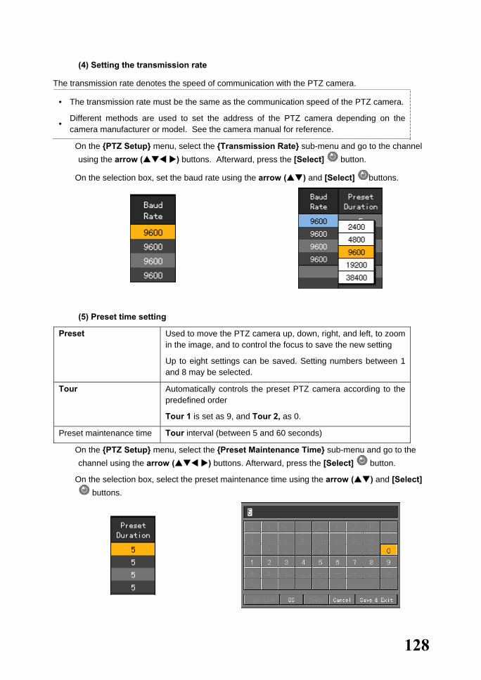
128
(4) Setting the transmission rate
The transmission rate denotes the speed of communication with the PTZ camera.
•
•
The transmission rate must be the same as the communication speed of the PTZ camera.
Different methods are used to set the address of the PTZ camera depending on the camera manufacturer or model. See the camera manual for reference.
� On the {PTZ Setup} menu, select the {Transmission Rate} sub-menu and go to the channel using the arrow ( ) buttons. Afterward, press the [Select] button.
� On the selection box, set the baud rate using the arrow ( ) and [Select] buttons.
(5) Preset time setting
Preset Used to move the PTZ camera up, down, right, and left, to zoom in the image, and to control the focus to save the new setting
Up to eight settings can be saved. Setting numbers between 1 and 8 may be selected.
Tour Automatically controls the preset PTZ camera according to the predefined order
Tour 1 is set as 9, and Tour 2, as 0.
Preset maintenance time Tour interval (between 5 and 60 seconds)
� On the {PTZ Setup} menu, select the {Preset Maintenance Time} sub-menu and go to the channel using the arrow ( ) buttons. Afterward, press the [Select] button.
� On the selection box, select the preset maintenance time using the arrow ( ) and [Select] buttons.

129
(6) Tour setting Preset Used to move the PTZ camera up, down, right, and left, to zoom in the
image, and to control the focus to save the new setting Up to eight settings may be defined. Setting numbers between 1 and 8 may be selected.
Tour Automatically controls the preset PTZ camera according to the predefined order
Tour 1 is set as 9, and Tour 2, as 0.
Preset maintenance time
Tour interval (between 5 and 60 seconds)
Example - Tour feature when Tour 1 and Tour 2 are set as follows:
When 9 is pressed in PTZ mode:Numbers are selected in the following order: 1 > 7 > 5 > 6. Selecting 9 again disables the feature.
When 0 is pressed in PTZ mode:Numbers are selected in the following order: 3 > 2 > 4 > 8. Selecting 0 again disables the feature.
Tour1 Tour2
1 3
7 2
5 4
6 8
� On the {PTZ Setup} menu, select the {Tour} sub-menu and go to the channel using the arrow
( ) buttons. Afterward, press the [Select] button.
� On the selection box, enable the Tour feature using the arrow ( ) and [Select] buttons.

130
5-2-3. Network Setup
(1) Selecting the Network Setup menu
� In {Additional Setup} mode, go to {Network} and press the [Select] button.
(2) Ethernet
Uses a fixed IP in the local area network environment
� On the {Network Setup} menu, go to {Ethernet} using the arrow ( ) buttons and press the
[Select] button.
○1
○2

131
� To select 1, 2, or 3, use the [Tab] button. For others, use the arrow ( ) buttons.
On the LAN Setup menu, set the LAN field. When changing the last part of the existing address:
a) Go to the input box using the arrow ( ) buttons and select the left arrow (�) button.
b) Go to [BS] using the [Tab] or arrow ( ) buttons. c) Delete only the incorrect value using the [Select] button. d) Enter the new value using the numeric buttons on the remote control or the arrow (
) and [Select] buttons.
BS Backspace; used to delete
Cancel Used to cancel the save Save and exit Used to save and exit
B) IP address setup
� On the {Ethernet Setup} menu, go to the IP address input field using the arrow ( )
buttons and press the [Select] button.

132
� On the input window, enter the IP address using the numeric buttons on the remote control or the arrow ( ) and [Select] buttons.
BS Backspace; used to delete
Cancel Used to cancel
Save and exit Used to save and exit
� After inputting the data, go to [Save and Exit] using the [Tab] or arrow ( ) buttons and
press the [Select] button.
C) Subnet mask setting
� On the {Ethernet Setup} menu, go to the subnet mask input field using the arrow ( ) buttons and press the [Select] button.
� On the input window, enter the subnet mask using the numeric buttons on the remote control or the arrow ( ) and [Select] buttons.
BS Backspace; used to delete
Cancel Used to cancel the save
Save and exit Used to save and exit
� After inputting the data, go to [Save and Exit] using the [Tab] or arrow ( ) buttons and
press the [Select] button.

133
D) Default gateway setting
� On the {Ethernet Setup} menu, go to the default gateway input field using the arrow ( )
buttons and press the [Select] button.
� On the input window, enter the default gateway using the numeric buttons on the remote
control or the arrow ( ) and [Select] buttons.
BS Backspace; used to delete
Cancel Used to cancel the save Save and exit Used to save and exit
� After inputting the data, go to [Save and Exit] using the [Tab] or arrow ( ) buttons and
press the [Select] button.
E) Default DNS setting
� On the {Ethernet Setup} menu, go to the default DNS input field using the arrow ( )
buttons and press the [Select] button.

134
� On the input window, enter the default DNS using the numeric buttons on the remote control or
the arrow ( ) and [Select] buttons.
BS Backspace; used to delete
Cancel Used to cancel the save
Save and exit Used to save and exit
� After inputting the data, go to [Save and Exit] using the [Tab] or arrow ( ) buttons and
press the [Select] button.
F) Auxiliary DNS setting
� On the {Ethernet Setup} menu, go to the auxiliary DNS input field using the arrow ( )
buttons and press the [Select] button.
� On the input window, enter the auxiliary DNS using the numeric buttons on the remote control
or the arrow ( ) and [Select] buttons.
BS Backspace; used to delete
Cancel Used to cancel the save Save and exit Used to save and exit
� After inputting the data, go to [Save and Exit] using the [Tab] or arrow ( ) buttons and
press the [Select] button.
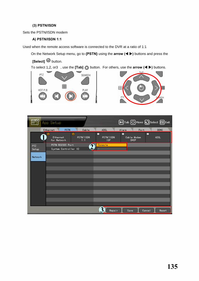
135
(3) PSTN/ISDN
Sets the PSTN/ISDN modem
A) PSTN/ISDN 1:1
Used when the remote access software is connected to the DVR at a ratio of 1:1
� On the Network Setup menu, go to {PSTN} using the arrow ( ) buttons and press the
[Select] button.
� To select 1,2, or3�, use the [Tab] button. For others, use the arrow ( ) buttons.
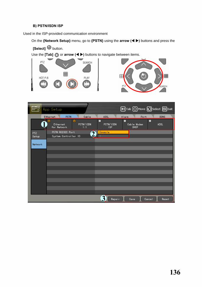
136
B) PSTN/ISDN ISP
Used in the ISP-provided communication environment
� On the {Network Setup} menu, go to {PSTN} using the arrow ( ) buttons and press the
[Select] button.
� Use the [Tab] or arrow ( ) buttons to navigate between items.
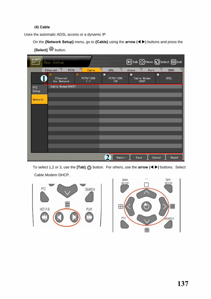
137
(4) Cable
Uses the automatic ADSL access or a dynamic IP
� On the {Network Setup} menu, go to {Cable} using the arrow ( ) buttons and press the
[Select] button.
� To select 1,2 or 3, use the [Tab] button. For others, use the arrow ( ) buttons. Select
Cable Modem DHCP.
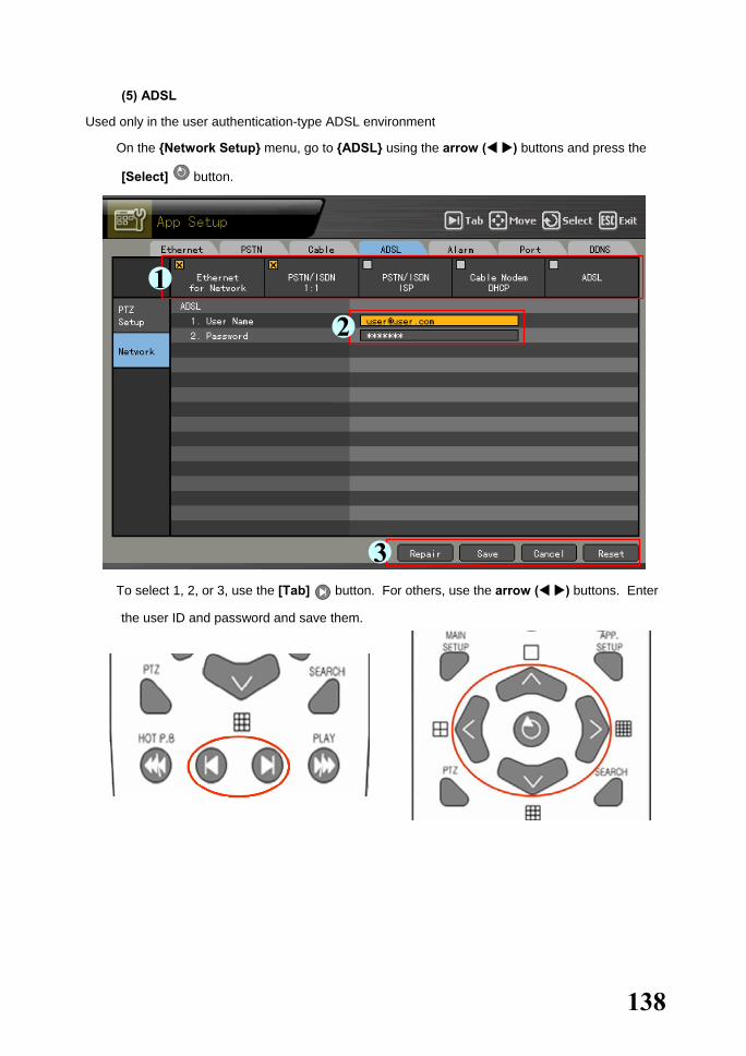
138
(5) ADSL
Used only in the user authentication-type ADSL environment
� On the {Network Setup} menu, go to {ADSL} using the arrow ( ) buttons and press the
[Select] button.
� To select 1, 2, or 3, use the [Tab] button. For others, use the arrow ( ) buttons. Enter
the user ID and password and save them.

139
(6) Alarm
Fixed phone or mail alarm output setting for the event
To use this feature, select {Main Setup} {Data Setup} and enable Call or Mail Alarm.
� On the {Network Setup} menu, go to {Alarm} using the arrow ( ) buttons and press the
[Select] button.
� To select 1, 2, or 3, use the [Tab] button. For others, use the arrow ( ) button. Set the
telephone number and the sending/receiving email addresses.

140
(7) Port
Sets the user for the network port
The default is between 2000 and 2007; a randomly chosen value may be used depending on the
network environment, e.g., firewall.
� On the {Network Setup} menu, go to {Port} using the arrow ( ) buttons and press the
[Select] button.
� Set the port number using the [Tab] and arrow ( ) buttons.

141
(8) DDNS
As part of the DNS system, the Dynamic Domain Name System (DDNS) service dynamically
updates the IP addresses of the host names and allocates fixed domain names to systems
connected with dynamic IP addresses. This way, the DDNS service ensures the user’s access to
the network using the same DNS name regardless of the changes in the IP address.
Workhorse/Premier Series provide a dynamic DNS to ensure URL access in a dynamic IP
environment. Its built-in web server feature enables remotely monitoring images through the
Internet anytime.
� Go to {DDNS} using the {Network Setup} menu and arrow ( ) buttons and press the [Select] button.
� Enable/Disable the use of DDNS using the arrow ( ) buttons as shown below:
� Register the domain name registered in the DNS server.
After accessing the DDNS server, register the domain name and enter a unique URL.
For more information on adding a domain please contact tech support at 866-301-2288

142
� Enter the DDNS access password registered in the DDNS server.
� Enter the IP address of the DDNS server. The default IP address of the DDNS server is 211.117.45.25.
� Set the default port of the DDNS server. The default port of the DDNS server is 9100.

143

144
1. Rugged Vision Viewer(Web monitoring) 1-1. Access The user can access the DVR system through the web.
� Enter the IP of the DVR system on the address field of the web browser.
� The ID and password are the same as those of the user account set in the DVR system. After
logging in to the system, install ActiveX for Windows XP SP2 or higher.

145
� Click [Install] on the window as shown below:
� After installing ActiveX, the user can use Plus Viewer on the web browser.
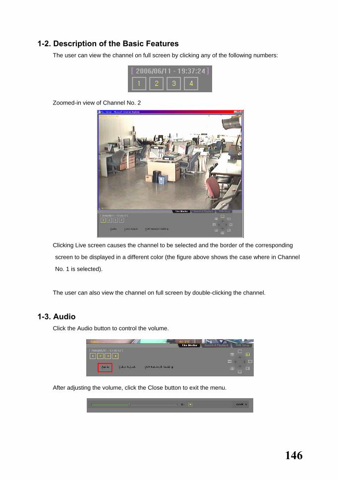
146
1-2. Description of the Basic Features � The user can view the channel on full screen by clicking any of the following numbers:
� Zoomed-in view of Channel No. 2
� Clicking Live screen causes the channel to be selected and the border of the corresponding
screen to be displayed in a different color (the figure above shows the case where in Channel
No. 1 is selected).
� The user can also view the channel on full screen by double-clicking the channel.
1-3. Audio � Click the Audio button to control the volume.
� After adjusting the volume, click the Close button to exit the menu.

147
1-4. Color Adjust � Click Color Adjust to adjust the display colors.
� After adjusting the display colors, click Close to save the setting and close the window.
1-5. DVR Network Setting � To view the DVR setting, click DVR Network Setting.

148
� Product information
1. Software version: 00 (build no.)
2. Hardware version
3. Video type
4. Hard drive information
Total space
Used space
Free space
Recording start day
Last recording date
5. Network setting information
6. Whether to allow overwriting or not
� Use Picture Setting to set the resolution, video quality, and frame speed.
Picture resolution Used to adjust the resolution; the lower the resolution, the higher the transmission speed (CIF > Field > Full) Picture quality Used to adjust the picture quality; the higher the picture quality, the higher the compression rate (in case of low picture quality, the network transmission rate increases) Enable temporal filter Removes any noise in the image to eliminate unnecessary data and enhance the network transmission speed Picture frame rate Controls the frame rate; the following are the frame rates for 30 frames: High: 30; Medium: 15; Low: 7.5

149
� Use Network Account to display the user profile.
1-6. Viewing a Divided Screen
After the channel video is displayed on the monitoring window, the user can view the divided screen by clicking the Division Mode button.
To view one channel on full screen, double-click the channel. To return to division mode, double-click any area on the screen.
Example - Selecting 4-division mode
4-division mode

150
1-7.Search and Playback Searches and plays the video recorded in a remote DVR in real time.
� Click the Search and Playback tab at the bottom.
1-7-2. Search Method
� Search –Displays the recorded video in the form of an hour/minute bar graph
� Search –Displays the recorded video in the form of a file list
1-7-3. Search and Play
� On the search window, click the or button and select the search
method.
� Select a date from the calendar. The date when a video was recorded video is marked.
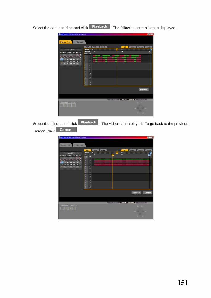
151
� Select the date and time and click . The following screen is then displayed:
� Select the minute and click . The video is then played. To go back to the previous
screen, click .
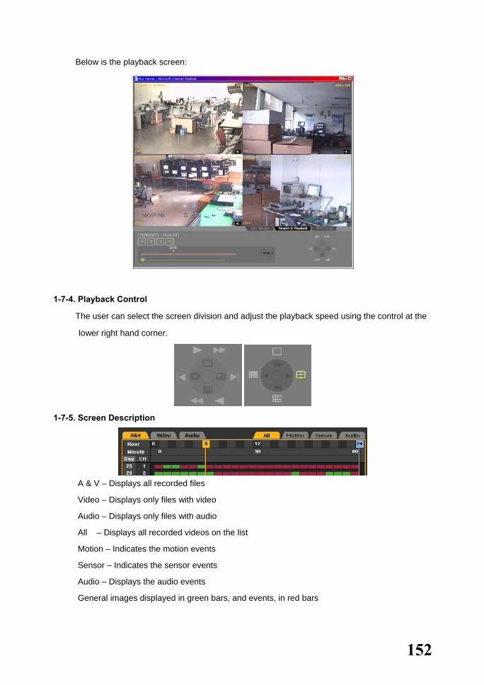
152
� Below is the playback screen:
1-7-4. Playback Control
� The user can select the screen division and adjust the playback speed using the control at the
lower right hand corner.
1-7-5. Screen Description
� A & V – Displays all recorded files
� Video – Displays only files with video
� Audio – Displays only files with audio
� All – Displays all recorded videos on the list
� Motion – Indicates the motion events
� Sensor – Indicates the sensor events
� Audio – Displays the audio events
� General images displayed in green bars, and events, in red bars

153
1-8. DVR Setup The remote DVR setup screen includes Graphic User Interfaces (GUIs) such as DVR OSD.
� Clicking causes the following screen to be displayed:
� Change the system setup on the DVR setup screen by clicking [System Setup].
For more information on system setup, see Chapter 5 (System Setup).
� After changing the system setting, click .
� Click the Send button to send the new system setting to the DVR and to complete the DVR
setting.

154
2. Quick Viewer When recorded data is backed up from the DVR system, a new folder is created in the backup
device including QuickViewer.exe and mwmp4dec.dll files. The user can run Quick Viewer by
executing QuickViewer.exe.

155
2-1. File Play � Click [File] – [Open]. An open file dialog box then appears as shown below:
� Select the rms file of the channel to be played.
2-2. Description of Buttons � Fast backward play
� Backward play
� Previous frame
� Next frame
� Forward play
� Fast-forward play
� Volume control

156
2-3. Version Information � To check the version of Quick Viewer, click [Help] – [About].

157
Workhorse 120-4 A/P/P/E/N/D/I/X
A/P/P/E/N/D/I/X ........................................................................................157 1. PTZ Camera Protocol .......................................................................158 2. Recommended HDD.........................................................................158 3. Recommended USB 2.0 Device.......................................................159
Memory Stick......................................................................................................159 2.5" Portable USB HDD......................................................................................159 CD-RW, DVD-RW ..............................................................................................159

158
1. PTZ Camera Protocol No. Vendor Protocol
1 CHOU COHU-3925
2 Kalatel KALATEL
3 Hitron FASTRAX2
4 Panasonic WVCS854, WV-CS850A, WV-CS854, WV-CW860 external
5 Dongyang DRX_500
6 Samsung SCC641
7 GSP CYBERSCAN_1
8 HONEYWELL HSDN251
9 PHILIPS PHILIPS
10 RIFATRON RIFATRON
11 VICON VICON
12 AMERICAN DYNAMICS SENSORMATIC
13 PELCO PELCO – D, PELCO - P
14 PROLINE PROLINE - UK
15 SAMSUNG TECHWIN SPD-1600
2. Recommended HDD NO Vendor Model Capacity Buffer RPM
1 Western Digital
WD WD1200
WD WD2500
120GB
250GB
2M
8M
7200
7200
2 Seagate
SEAGATE BARRACUDA 7200.9 ST3120213A
SEAGATE BARRACUDA 7200.7 ST3160023A
SEAGATE BARRACUDA 7200.7 ST3200822A
SEAGATE BARRACUDA 7200.7 ST3200827A
SEAGATE BARRACUDA 7200.9 ST3250823A
SEAGATE BARRACUDA 7200.9 ST3250824A
SEAGATE BARRACUDA 7200.8 ST3300831A
SEAGATE BARRACUDA 7200.8 ST3400832A
SEAGATE BARRACUDA 7200.9 ST3250641A
120GB
160GB
200GB
200GB
250GB 250GB
300GB
400GB
500GB
8M
8M
8M
8M
8M
8M
8M
8M
8M
7200
7200
7200
7200
7200
7200
7200
7200
7200
3 Samsung Samsung SP1203N/DOM
Samsung SP2514N/OMD
120GB
250GB
2M
8M
7200
7200
4 MAXTOR
MAXTOR DIAMOND MAX 10
MAXTOR DIAMOND MAX 10
MAXTOR DIAMOND MAX 10
MAXTOR DIAMOND MAX 11
160GB
200GB
250GB
500GB
8M
8M
8M
7200
7200
7200
7200

159
3. Recommended USB 2.0 Device USB 2.0 Device Media File System
Memory Stick Flash type FAT32
2.5" Portable USB HDD HDD type FAT32
CD CD R, R/W ISO9660
DVD DVD -R, -RW, +R, +R/W ISO9660
Memory Stick No. Vendor Model Capacity
1 Transcend Ultra Speed JetFlash 256MB
2 FM semiconductor MemoRive USB 2.0 256MB
3 LG Xtick USB Drive 256MB
4 AL Tech ANYDRIVE mini-USB 256MB
5 Kingston DataTraveler USB FLASH DRIVE 256MB
6 Sarotech FLEX FD-03U1 128MB
8 Sandrive Cruzer Mini 128M
10 Samsung PLEOMAX 128MB
11 Sony Micro Vault 128M
2.5" Portable USB HDD No. Vendor Model Capacity
1 IT Mall neo Q Plus USB 2.0 20GB
2 USBNET Anypak USB 2.0 20GB 20GB
CD-RW, DVD-RW Vendor Model
SONY DRX-810UL
PX-716UF Plextor
DVR-A09XLB
SE-W164 SAMSUNG
TS-H292A
SOHR-5239S Lite On
SHW-1635S
GCE-8527B
GSA-4163B
GSA-4,167B LG
LGE-DMGSA-H10L (B)

160