stateless datacenter load-balancing with beamer · load balancing decision per connection and then...
TRANSCRIPT

This paper is included in the Proceedings of the 15th USENIX Symposium on Networked
Systems Design and Implementation (NSDI ’18).April 9–11, 2018 • Renton, WA, USA
ISBN 978-1-931971-43-0
Open access to the Proceedings of the 15th USENIX Symposium on Networked
Systems Design and Implementation is sponsored by USENIX.
Stateless Datacenter Load-balancing with BeamerVladimir Olteanu, Alexandru Agache, Andrei Voinescu, and Costin Raiciu,
University Politehnica of Bucharest
https://www.usenix.org/conference/nsdi18/presentation/olteanu
Stateless Datacenter Load-balancing with BeamerVladimir Olteanu, Alexandru Agache, Andrei Voinescu and Costin Raiciu
University Politehnica of Bucharest
AbstractDatacenter load balancers (or muxes) steer traffic des-tined to a given service across a dynamic set of backendmachines. To ensure consistent load balancing decisionswhen backends come or leave, existing solutions make aload balancing decision per connection and then store it asper-connection state to be used for future packets. Whilesimple to implement, per-connection state is brittle: SYN-flood attacks easily fill state memory, preventing muxesfrom keeping state for good connections.
We present Beamer, a datacenter load-balancer that isdesigned to ensure stateless mux operation. The key ideais to leverage the connection state already stored in back-end servers to ensure that connections are never droppedunder churn: when a server receives a mid-connectionpacket for which it doesn’t have state, it forwards it toanother server that should have state for the packet.
Stateless load balancing brings many benefits: oursoftware implementation of Beamer is twice faster thanGoogle’s Maglev, the state of the art software load bal-ancer, and can process 40Gbps of HTTP uplink trafficon 7 cores. Beamer is simple to deploy both in soft-ware and in hardware as our P4 implementation shows.Finally, Beamer allows arbitrary scale-out and scale-inevents without dropping any connections.
1 IntroductionLoad balancing is an indispensable tool in modern dat-
acenters: Internet traffic must be evenly spread across theservers that deal with client requests, and even internaldatacenter traffic between different services is load bal-anced to ensure independent scaling and management ofthe different services in the datacenter.
Existing load balancer solutions can load balance TCPand UDP traffic at datacenter scale at different price points[26, 13, 9, 22, 15, 31, 12, 18]. However, they all keepper-flow state: after a load balancer decides which servershould handle a connection, that decision is “remem-bered” locally and used to handle future packets of thesame connection. Keeping per-flow state should ensurethat ongoing connections do not break when servers andmuxes come or go, but has fundamental limits:• Standard scaling events that include both muxes and
servers break many ongoing connections.• SYN flood attacks prevent muxes from keeping
“good” connection state, negating its benefits.• Running stateful load-balancers in software with
many flows reduces throughput by 40% (§6.1).
In this paper we design, implement and test Beamer,a stateless and scalable datacenter load balancer thatsupports not only TCP, but also Multipath TCP [27]. Thekey idea behind Beamer is daisy chaining that uses theper-connection state already held by servers to forwardoccasional stray connections to their respective owners.
Our prototype implementation can forward 33 millionminimum-sized packets per second on a ten core server,twice as fast as Maglev [9], the state of the art load bal-ancer for TCP traffic. Our stateless design allows us tocheaply run Beamer in hardware too, as shown by our P4implementation (§5). Beamer can scale almost arbitrarilybecause each load balancer acts completely independentlyand holds no per-connection state. Our experiments showthat Beamer is not only fast, but also extremely robust tomux and server addition, removal or failures as well asheavy SYN flood attacks.
2 BackgroundServices in datacenters are assigned public IP addresses
called VIPs (virtual IP). For each VIP, the administratorconfigures a list of private addresses called DIPs (directIPs) of the destination servers. The job of the load bal-ancer is to load balance connections destined to the VIPsacross all the DIPs. Hardware load balancing applianceshave long been around and are still in use in many lo-cations; however they are difficult to upgrade or modifyand rather expensive. Traditional app-level proxies suchas HAProxy or Squid that terminate the client’s TCP con-nection and open a new one to the server are also not de-sirable because their performance is quite low.
A raft of load balancers based on commodity hardwarehave been proposed that seek to address the shortcom-ings of existing solutions [26, 9, 13, 12, 18, 22, 15, 31].Their goal is to process packets as cheaply as possible,while balancing load evenly across a dynamically chang-ing population of backend servers and ensuring connec-tion affinity: all packets of a connection should reach thesame server.
Almost all existing load balancers follow the same ar-chitecture introduced by Ananta [26] and we provide abrief description in Figure 1. In Ananta, load balancingis performed using a combination of routing (Equal CostMultipath) and software muxes running on commodityx86 boxes. All muxes speak BGP to the border datacen-ter router and announce the VIPs they are in charge of asaccessible in one hop. The border router then uses equal-cost multipath routing (ECMP) to split the traffic equally
USENIX Association 15th USENIX Symposium on Networked Systems Design and Implementation 125

MUX1 MUX2 …
Server Server Server …
Border router
ECMP VIP VIP
DIP1 DIP2 DIP3
1 C VIP srcIP dstIP
2
3 MUX2 DIP3 C VIP
payload
4 VIP C C VIP
Figure 1: Load balancing: traffic to the VIP addressis load-balanced across a pool of servers, each witha DIP address. Return traffic bypasses the muxes.
MUX
Server
Client
1SYN
2SYN
3 SYN/ACK
X
Figure 2: Mux and serverdisagree over the status of aconnection.
A
Add mux 2 and server B
MUX 1
A
MUX 1
B
MUX 2
X
Higher load
Figure 3: Scale out: statefulload balancers break TCP con-nections.
to these muxes. When a connection starts (i.e. a SYNpacket arrives at a mux), a hash function is applied on thefive-tuple and a server is chosen based on this hash. If asingle server is added to the DIP pool, the assignment ofsome existing connections to servers will change; at thevery least, the new server must receive an equal fractionof all ongoing connections. That is why, once a mappingof connection to DIP is chosen, it is stored locally by themux to ensure all future packets will go to the same DIP.
Upon leaving the mux, the original packet is encapsu-lated and sent to the DIP. The receiving server first decap-sulates the packet, changes the destination address fromVIP to DIP, and then processes it in the regular TCP stack.When the reply packet is generated, the source address ischanged from DIP to VIP and the packet is sent directlyto the client, bypassing the mux to reduce its load (this isDirect Source Return, or DSR).
3 Limits of stateful load balancingA key design decision of all existing load balancers is
to keep a small amount of per-connection state to ensureconnection affinity: once a connection is assigned to abackend, the mux will remember this decision until theconnection finishes or a timer fires.
While per-connection state works well in the averagecase, it has a number of fundamental limitations which re-duce its effectiveness in practice. First, because the muxonly sees one direction of traffic, state kept by the muxcan differ from the server’s state for the same connection;the worst case here is the muxes’ inability to cope withSYN flood attacks. Secondly, even in the absence of SYNfloods, connections will be broken in scale-out or scale-in(or failure) events where both the mux set and the DIPschange simultaneously; such events happen naturally. Fi-nally, software muxes’ forwarding performance decreaseswith many active connections (see §6). We discuss theseissues next.State mismatch between mux and server. Consider thesimple example in Figure 2: a client starts a TCP con-nection by sending a SYN packet, which is seen by a
mux and then redirected to a server, and the mux savesthe chosen mapping locally. The server replies with aSYN/ACK packet which never reaches its destination be-cause the client is now disconnected. The server will sendthis packet a few times until it terminates the connection;the mux however is not aware of the reverse path unreach-ability and will maintain the state for minutes.
SYN flood attacks, where attackers send many SYNpackets with spoofed IP source addresses [8], cause sim-ilar problems. During a SYN flood, the SYN/ACKs sentby the server never reach their destination, but both theserver and the mux install connection state. SYN-cookies[8] are the standard protection against SYN flood at-tacks: when the number of half-open connections reachesa threshold, the server stops keeping state upon receiv-ing a SYN, encoding the state in the SYN/ACK packet itsends to the client. When legitimate customers reply withthe third ACK to finalize the connection handshake, theserver uses the information from the ACK number (a re-flection of its initial sequence number) and the timestamp(the echo reply field) in conjunction with local informa-tion to check if this is a valid connection; if so, it createsan established connection directly.
SYN cookies help the server shed unwanted state, buthave no positive effect at the mux: the mux is forced toallocate state for every SYN it sees. Under a SYN floodattack, the servers will function normally but the muxes’connection memory will be overloaded to the point wherethey will behave as if they have no connection state, andthus DIP churn will break connections.
Ensuring state synchronization and defending againstSYN floods at muxes is far from trivial: at the very least itrequires muxes to keep more state (i.e. is the server send-ing SYN cookies or not?) and examine both directions oftraffic; another cleaner solution is for the mux to terminateTCP. All solutions limit scalability.Connection failures during scaling events. Even with-out SYN floods, keeping mux state does not guaranteeconnection affinity. Figure 3 shows a datacenter servicethat is running with one mux and one server. As load in-creases, one more mux and server are added. The border
126 15th USENIX Symposium on Networked Systems Design and Implementation USENIX Association
router now routes half the connections it sent to mux 1 tomux 2, as the blue flow in our example. Mux 2 does nothave state for the blue flow, and it simply hashes it, as-signs it to B and remembers the mapping for future pack-ets. B receives packets from an unknown connection soit resets it. Such failures happen even when the borderrouter uses resilient hashing and when all muxes use thesame hash function. The necessary condition, though, isthat both the mux set and the server set changes in quicksuccession, but such sequences of events occur naturallyin datacenters during scale out and scale in events.
4 Beamer: stateless load-balancingUsing per-flow state at muxes fails to provide connec-
tion affinity in many cases. Can we do better withoutkeeping flow state in the muxes? This is our goal here.
To achieve it, we leverage the per-flow state serversalready maintain for their active connections. As an ex-ample, consider server B in Fig. 3: it receives a packetbelonging to the blue connection, for which it does nothave an entry in the open connections table; the defaultbehaviour is to reset the blue connection. If B knew thatserver A might have state for this connection, it could sim-ply forward all packets it doesn’t have state for, includingthe blue connection, to A, where they could be processednormally. We call such forwarding between servers daisychaining and it is the core of Beamer.
The architecture of Beamer mirrors that in Figure 1: ourmuxes run BGP (Quagga) and announce the same VIPto border routers. ECMP at the routers spreads packetsacross the muxes, which direct traffic to servers; finallythe servers respond directly to clients. To build a scalabledistributed system around daisy chaining, Beamer usesthree key ingredients:• Stable hashing (§4.1), a novel hashing algorithm that
reduces the amount of churn in DIP pool changes tothe bare minimum, while ensuring near-perfect loadbalancing and ease of deployment.• A fault-tolerant control plane(§4.5) that scalably dis-
seminates data plane configurations to all muxes.• An in-band signaling mechanism that gives servers
enough information for daisy chaining, without re-quiring synchronization (§4.2).
4.1 Stable hashingBeamer muxes hash packets independently to decide
the server that should process them. A good hashing algo-rithm must satisfy the following properties: it should loadbalance traffic well, it should ensure connection affinityunder DIPs churn, and it should be fast.
A strawman hashing algorithm is to chose the targetserver by computing hash(5tuple)%N, where N is thenumber of DIPs; this is what routers use for ECMP. Thismechanism spreads load fairly evenly and as long as theset of DIPs doesn’t change, and mux failures or additionsdo not impact the flow-to-DIP allocations. Unfortunately,when a single server fails (or is added), most connectionswill break because the modulus N changes.
Consistent hashing [19], rendezvous hashing [30] andMaglev hashing [9] all offer both good load balancing andminimize or at least reduce disruption under churn. On thedownside, in all these algorithms each server is in chargeof many discontiguous parts of the hash space; this meansthe mux must match five-tuple hashes against many rules,reducing performance (for software deployments) or in-creasing hardware cost (for hardware ones). These algo-rithms target wide-area distributed systems and thus striveto reduce (mux) coordination. In datacenters, however,we can easily add lightweight coordination which enablesa simple and near-optimal hash algorithm.
Beamer implements stable hashing, an extensible hash-ing approach that can be used to implement all the algo-rithms above. Stable hashing adds a level of indirection:connections are hashed against a fixed number of buck-ets, and each bucket can be mapped by the operator toany server. Before the load balancing service starts for acertain VIP, the operator chooses a fixed number of buck-ets B that is strictly larger than N, the maximum numberof DIPs that will serve that VIP (e.g. B=100N). Eachbucket is assigned to a single server at any time, and eachserver may have multiple buckets assigned to it. The num-ber of buckets B and the bucket to server assignmentsare known by all muxes, and they are disseminated viaa separate control plane mechanism (see §4.5). When apacket arrives, muxes hash it to a bucket by computingb=hash(5tuple)%B, and then forward the packet tothe server currently assigned bucket b. As B is constantby construction, server churn does not affect the hashingresult: a connection always hashes to the same bucket,regardless of the number of active DIPs.
Bucket-to-server mappings are changed on server fail-ure or explicitly by the administrator for load-balancingand maintenance purposes. These mappings are storedin reliable distributed storage (Apache ZooKeeper [16] inour implementation); muxes retrieve the latest version be-fore they start handling traffic. As changes to the bucket-to-DIP mappings are rare, this mechanism has low com-munication overhead and scales to datacenter-sizes (§6.4).
We show an example of stable hashing in Figure 4.The administrator has configured four buckets; muxesfirst hash flows into these buckets to find the destination
USENIX Association 15th USENIX Symposium on Networked Systems Design and Implementation 127

MUX
b) Server B fails
Fixed number of buckets
MUX
B C X X
hash
A B C A A C C A
A B C
a) Stable hashing with three servers
A
hash
Figure 4: Stable hashing is resilient toserver failures.
������
����������
������
Figure 5: Hashing algorithmscomparison
MUX 2
MUX 1
B A B a) Buckets belong to server A
b) Buckets moved to B, Inconsistent mappings.
A A A A A MUX 1
A A MUX 2
B A B B
A
A
Figure 6: Daisy chaining allows serveraddition or removal without disruptingongoing connections.
server. When server B fails, the controller will move thethird bucket from B to C; the mapping is then stored inZooKeeper and disseminated to all muxes. After the map-ping is updated, flows initially going to A or C are unaf-fected, and flows destined for B are now sent to C. Onlythe blue connection, handled by B, is affected.
Our bucket-to-server mappings are managed centrallyby the controller. The controller has the freedom to im-plement any bucket-to-server mapping strategy to mim-ick consistent hashing, rendezvous hashing or Maglev. Inour implementation we chose a greedy assignment algo-rithm that aims to maximize the contiguous bucket rangesassigned to muxes; this is very useful especially whenBeamer is deployed in hardware, because it can use fewerTCAM rules to implement its dataplane functionality. Toprovide intuition about why this is the case, in Fig. 5 weshow how 47 buckets are assigned to 5 servers using thethree algorithms, where each server is shown in a differentcolour: the bigger the fragmentation, the higher the costto match packets against packets in the dataplane. Beameris the least fragmented, followed by Consistent and Ma-glev. When servers come and go, bucket assignments toservers will also become fragmented even with Beamer;Beamer runs a periodic defragmentation process to avoidthis issue (see §4.5).
Our stateless design ensures that mux churn has no im-pact on connections: as soon as BGP reconverges to thenew configuration, load will be spread equally across allmuxes and no connections will be broken.
4.2 Daisy chainingThere is a natural amount of churn of servers behind
a VIP, be it for load balancing purposes or for plannedmaintenance. To implement such a handover, all our con-troller has to do is to map to the new server the bucketsbelonging to the old server and store the new mappings inZooKeeper. The muxes will then learn the new mappingand start sending the bucket traffic to the new server. Fora truly smooth migration, however, there are two compli-cations that need to be taken in account: existing connec-tions will be broken and there might be inconsistencies
when some muxes use the new mappings while others areusing the old ones.
To solve both issues we use daisy chaining, a transi-tory period where both the new server and the old one areactive and servicing flows that hit the migrated bucket(s).We aim to move all new connections to the new server,and process ongoing connections by forwarding them tothe old server even if they arrive at the new server.
We give an example in Fig. 6 where we migrate threebuckets between servers A and B. Initially, both muxeshave the same mappings for all buckets. Daisy chainingstarts when the controller migrates the buckets from A toB by storing the new mapping in ZooKeeper and markingA as the previous DIP, along with the timestamp of the up-date. Note that the muxes save the previous DIP for eachbucket, as well as the time the reallocation took place.To see how daisy chaining comes into play, let us con-sider the way packets are processed upon reception by theserver. If the incoming packet is a SYN (TCP or MPTCP),a valid SYN-cookie ACK, or it belongs to a local connec-tion, then we can process it locally. Otherwise, the packetcould belong to a connection that has been previously es-tablished on another server. In this case, we want to daisy-chain packets back to the appropriate server, but only fora limited time.
To enable this, packets destined to ports lower than1024 (higher numbers are used for MPTCP load balanc-ing, see §4.4) also carry the previous DIP and the times-tamp of the change (or 0 when there is none). We alwayssave locally the highest timestamp seen for the bucket thepacket is hashed to, and enable daisy chaining to the pre-vious DIP when current time is smaller then the times-tamp plus the daisy chaining interval. Thus, packets areredirected to the appropriate destination as long as daisychaining is active. Otherwise, they are dropped and a RSTis sent back to the source.
Daisy chaining adds robustness to our whole design.Consider what happens if the two muxes in Fig. 6 tem-porarily disagree on the server now in charge of the threebuckets. Flows that hit mux 1 are load balanced accord-ing to the old mapping and will be directed to A, who
128 15th USENIX Symposium on Networked Systems Design and Implementation USENIX Association

will simply process them locally (the black connection).Meanwhile, B will locally service the red connection, butwill daisy chain the blue connection to A (the previousDIP) because it doesn’t have state for it. When mux 1 fi-nally updates its state, the black connection will be sent toB, and daisy chained back to A (assuming the rule is stillactive). After all the muxes have updated their state, Awill only receive packets related to ongoing connections,which will quickly drop in number. While in principledaisy chaining can be left running forever, we try to avoidmigrating buckets that are being daisy chained. That iswhy our Linux kernel implementation uses a hard timeoutof four minutes for daisy chaining.
There is one subtle corner case where daisy chainingstill doesn’t protect against broken connections, and weexemplify in figure 6. Consider the red connection that isbeing serviced by B after mux 2 updates its configuration;if this connection is sent to mux 1 (e.g. via ECMP churnin BGP), mux 1 will send it to server A which will resetit. To avoid this problem, packets also carry the genera-tion number for the dataplane information, and all serversremember the highest generation number they have seen.In this example, server A will receive packets from B (andpossibly from other muxes) with generation 2 and will re-member 2 as the latest generation. When A receives amid-connection packet that can not be daisy chained andfor which it has no state, it will check if the generationnumber from the mux equals the highest generation num-ber seen; if yes, the connection will be reset. If not, theserver silently discards the packet. This will force theclient to retransmit the packet, and in the meantime thestale mux mappings will be updated to the latest genera-tion, solving the issue. Note that, if the border router usesresilient hashing, the mechanism above becomes nearlysuperfluous.
4.3 Mux data plane algorithmThe mux data plane algorithm pseudocode is shown
in Fig.7. Lines 3-9 handle regular TCP traffic: first thebucket b is found together with the current and previousDIPs for bucket b. After that, the packet is encapsulatedand sent to the current DIP. The algorithm is very sim-ple, requiring a hash and one memory lookup in the buck-ets matrix (all three columns easily fit in one cache line).The remaining code in the mux performs Multipath TCP(MPTCP) [27] traffic load balancing equally cheaply: asingle lookup is needed and the packet is encapsulated andsent to the appropriate DIP (see §4.4).
The simplicity of the mux is key to good performance:on one core our prototype can handle around 5-6Mpps,and around 33Mpps on an ten core Xeon box.
1 packet* mux(packet* p){2 if (p->dst_port<1024){3 gen = buckets.version4 b = hash(5-tuple)%B;5 dip = buckets[b][0];6 pdip = buckets[b][1];7 ts = buckets[b][2];89 return encapsulate(mux,dip,pdip,ts,gen,p);10 }11 else {12 dip = id[p->dst_port];13 return encapsulate(mux,dip,p);14 }15 }
Figure 7: Mux data plane pseudocode
4.4 Handling Multipath TCPMPTCP deployment on mobiles is spreading: all IOS-
based phones have it, as do top-end Android devices suchas Galaxy S7 / S8. None of the existing datacenter loadbalancers support MPTCP, unfortunately, and this is a bar-rier to server-side deployment. This is because load bal-ancing MPTCP is more difficult than regular TCP.
An MPTCP connection contains one or more subflows,and it starts when its first subflow is created. Each subflowlooks very much like an independent TCP connection tothe network, with the exception that its segments carryMPTCP-specific options. When load balancing MPTCP,all subflows of the same connection must be sent to thesame DIP. Existing datacenter load balancers (e.g. Ananta[26], Maglev [9], SilkRoad [22], Duet [13]) treat MPTCPsubflows as independent TCP connections, thus the DIPfor each subflow will be decided independently, sendingthem to different servers most times, and breaking sec-ondary subflows.
In MPTCP, after the initial subflow is setup, each end-point computes the token—a unique identifier its peerhas assigned to this connection. This token is embeddedin the handshake of additional subflows within the sameMPTCP connection and helps the remote end find the ap-propriate connection to bind the subflow to.
If one follows the mux state design approach, imple-menting MPTCP support requires storing the server-tokenTB to DIP mapping in some shared memory all muxes canaccess, but this poses two problems: first, since only theDIP knows the token, it should update the shared mem-ory when a new connection is created; secondly, having ashared memory access for each additional subflow wouldbe prohibitive from a performance point of view.
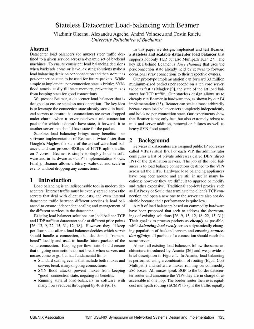
We propose a stateless solution that leverages the mo-bility support available in MPTCP to ensure that sec-ondary subflows can be forwarded to the correct server.We use the destination port in SYN JOIN packets to en-code the server identifier. This is shown in Fig. 8: when
USENIX Association 15th USENIX Symposium on Networked Systems Design and Implementation 129
LTE interface
Wifi interface
VIP SYN (MPC) to VIP, 80
SYN/ACK (TB)
ACK to VIP,80
ACK (ADD_ADDRESS VIP,1050)
SYN (JOIN, TB) to VIP, 1050
SYN/ACK (JOIN)
ACK to VIP,1050
A B
Used for OS demulNplexing
Used for Beamer load balancing
Used for OS demulNplexing
Figure 8: Load balancing MPTCP statelessly. Beameruses address advertisement to embed the server identifierin the destination port of secondary subflows.
receiving TCP SYN or MPTCP initial subflow SYN pack-ets, the port number is used to find the listening socket.However, SYN JOIN packets (handshake of secondarysubflow) contain a token (TB) that servers use to find theexisting MPTCP connection [11]; the destination port isnot used by the stack and we use it for Beamer.
Before deployment, Beamer assigns each server aunique identifier in the 1025-65535 range. We reserveport numbers (1-1024) for actual services, and utilize theremaining port numbers to encode server identifiers forsecondary subflows. MPTCP allows endpoints to sendadd address options that specify another address/portcombination of the endpoint to be used in future subflows.We use this functionality as shown in Fig. 8: whenever anew MPTCP connection is established (i.e. the third ACKof the first subflow is received), servers send an ACK withadd address option to the client with the VIP addressand the server identifier as port number. The client re-members this new address/port combination and will sendsubsequent subflows to it.
To handle MPTCP secondary subflows correctly, ourmux (Fig. 7) treats traffic differently depending on thepacket’s destination port: traffic to ports greater than 1024are treated as secondary subflows and directed to the ap-propriate servers. As each server has exactly one portassociated to it, our solution can support at most 64Kservers for each VIP. The muxes use another indirectiontable called id, that simply maps port numbers to DIPaddresses (identified with Di here, see Fig. 9).
Note that we only need daisy chaining to redirect initialsubflows of MPTCP connections or plain TCP connec-tions. Secondary subflows are sent directly to the appro-priate server (uniquely identified by the port).
4.5 Beamer control planeWe have designed our control plane to be scalable and
reliable and built it on top of ZooKeeper. ZooKeeperensures reliability by maintaining multiple copies of the
data and using a version of two-phase commit to keepthe copies in sync. Users can create hierarchies of nodes,where each node has a unique name and can have dataassociated to it, as well as a number of child nodes.
We show the operation of our control plane by detailinghow the most important operations are implemented. Thecontroller is the only machine that writes information intoZooKeeper and muxes only read ZooKeeper information.Servers do not interact with ZooKeeper at all. The nodehierarchy used by Beamer is shown in Fig. 11.
When a new Beamer instance is created, the con-troller creates a high level node (called in this example“beamer”) and a “config” child node holding the basicconfiguration information including the VIP and the to-tal number of buckets. Next, the operator can add DIPs tothe load balancer instance by specifying the DIP address,an identifier (unique within an instance) and a weight.
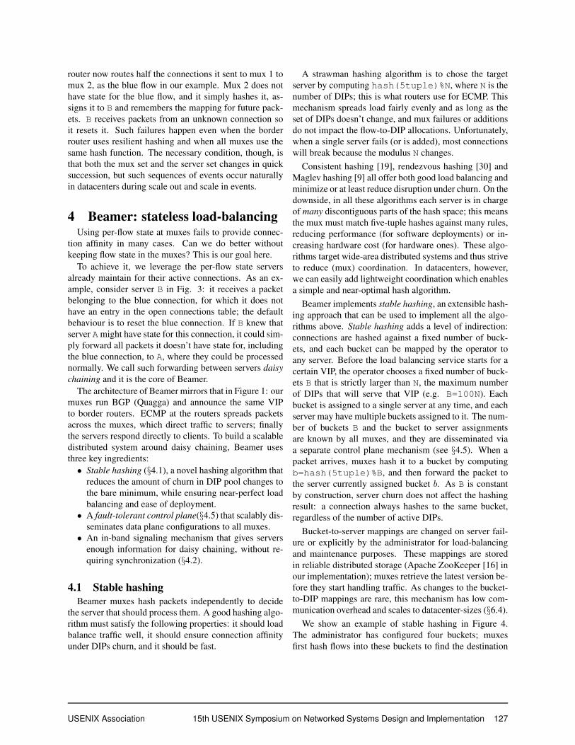
The bucket-to-server assignments are stored in the“mux ring”, while the “dips” node contains DIP-relatedmetadata, which is not read by the muxes.Creating a DIP. To add a DIP, the controller will addan entry for the DIP in the “dips” node, and then in the“id” node. ZooKeeper guarantees that all individual op-erations are atomic. If the controller or its connection toZooKeeper crashes at any point, it checks the “dips” nodefor any in-progress DIP additions. If a DIP is not repre-sented in the “id” node, it is added there as well.Load balancing is run after one or more DIPs are added,before they are removed or after their weight is changed.The assignment algorithm runs in a loop, aiming to bal-ance load properly while reducing daisy chaining:• Select the most overloaded server A and underloaded
server B, where load is the ratio between assignedbuckets and weight.
• Find the maximum number of buckets n such that, iftransferred from A to B, A’s load would not fall underthe average, and B’s load would not rise above.
• Select the n buckets that have been in A’s pool forthe longest time, and move them from A to B.
To move buckets between two servers, the controller sim-ply updates the mux ring (see below). Our greedy bucket-to-DIP assignment algorithm will cause fragmentationwhen the DIP set is altered and buckets are reassigned toensure good balancing. Beamer includes a defragmenta-tion algorithm (see Appendix) that runs when fragmenta-tion exceeds a threshold.Removing a DIP begins by setting its weight to zero. Af-ter running the load balancing algorithm, the “dips” entryis removed.Updating mux dataplane configuration safely. Themuxes load the dataplane configuration from the
130 15th USENIX Symposium on Networked Systems Design and Implementation USENIX Association
DIP PDIP TS
D1 D5 100
D6 D0 200
D1 D5 100
… … …
DIP
D1
D6
…
id buckets
B en
tries
64K en
tries
Figure 9: Mux data structures
mux ring
gen1
latest_gen
latest_blob
blob0 Timestamp D1, #buckets, list D2, #buckets, list …
0
2
DIP PDIP TS
D1 D5 100
D1 D5 100
… … …
log0
gen0 gen2
Figure 10: Mux configuration informa-tion stored in ZooKeeper
beamer config
bucket count VIP
mux_ring
id
141.85.37.8 6.4M DIP1, id1, weight1 DIP2, id2, weight2 …
DIPS
Figure 11: Controller informa-tion stored in ZooKeeper
“mux ring” node in ZooKeeper, as shown in Fig. 10.The dataplane information is stored in several generationnodes, that have logs, which capture incremental updatesto bucket ownership. Optionally, a generation node mayalso have a blob, which is an entire snapshot of the data-plane. The logs and blobs are compressed using zlib [1],and may span multiple nodes1.
The blob contains the same data structure used by themuxes to forward packets. When it starts up, the mux firstreads the values of “latest blob” (the newest generationthat contains a blob, in this case “gen0”). The mux readsthe blob from “gen0” and obtains a functional forwardingtable. If the “latest gen” node has a value greater than thelatest blob, the mux reads all the generations in ascendinggeneration number order and applies the deltas containedtherein. The mux now has an up-to-date forwarding tableand can process packets.
ZooKeeper allows clients to register watches on nodesand it delivers notifications when the nodes’ data is up-dated. We leverage this functionality to inform muxes thatthe forwarding information has changed: all muxes regis-ter watches for the “latest gen“ node; when it changes, themuxes will fetch and apply the new deltas.
Finally, the controller updates the mux ring informa-tion with the following algorithm: a) create a new genera-tion node and store the updates to the bucket-to-server as-signments, and b) update the “latest gen” node to informthe muxes of the new version. The controller also createsblobs by applying the deltas in the same way the muxesdo, creating the blob nodes under the current generationand then updating the “latest blob” entry.Safety. The controller algorithm above does not requireany synchronization between muxes or the controller be-yond ZooKeeper interactions. To ensure correctness, itmaintains the following invariants: a) Muxes only readZooKeeper information; they never update it. Configura-tion information is only written by the fault-tolerant con-troller; b) State updates are atomic from the muxes’ pointof view: they occur when the “latest gen” node is changed
1ZooKeeper nodes have a maximum size of 1MB.
Ingress
Egress
Match Ac/on
* b = CRC32 (5tuple)
HASH table
Match Ac/on
* b = b%B
MODULO table
Match b
Ac/on
0 Encap(D1,D5,100)
1 Encap(D6,D0,200)
… …
BUCKETS table
Match TCP.DST
Ac/on
1024 Encap(D1) 1025 Encap(D2) … …
ID table
TCP.DST<=1024 AND b is set
Figure 12: P4 implementation of a Beamer mux.
(an atomic ZooKeeper operation), which only occurs afterthe controller has finished writing the data pertaining tothe newest generation; and c) Generations with an iden-tifier smaller than “latest blob” can be safely deleted bythe controller since muxes do not need them to have anup-to-date version of the dataplane.
5 ImplementationBeamer servers run a kernel module (1300LOC) that
handles decapsulation, address mangling and daisy-chaining. We have also patched the MPTCP Linux kernelimplementation (version 0.90) to advertise the server IDfor subsequent subflows (a few tens of lines of code). Ourcontroller is implemented in 2100 lines of Java.
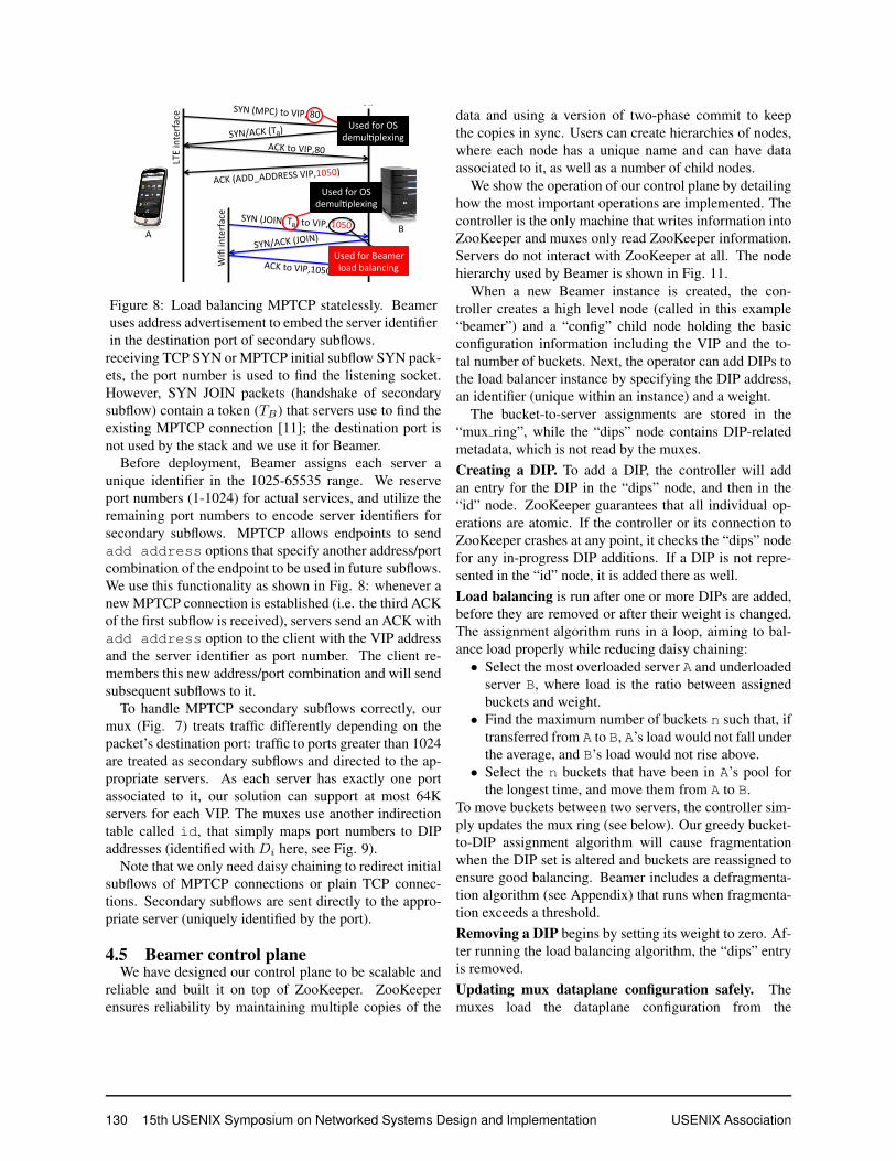
We have implemented Beamer muxes both in softwareand hardware (P4). The software mux runs a Click con-figuration atop the FastClick suite [4]. FastClick enablesscaling to multiple cores, sets thread to core affinities anddirectly assigns NIC queue interrupts to cores.Software mux. The core of the software mux is a Clickelement we have developed that implements our mux al-gorithm and acts as a ZooKeeper client to receive state up-dates. To improve performance, our design is completelylock free, which we achieve by carefully ordering the waywe update the buckets matrix during updates.Our hardware mux implementation is based on P4 [5]and is shown in Fig. 12. It contains two match-action
USENIX Association 15th USENIX Symposium on Networked Systems Design and Implementation 131

��
��
��
��
��
���
���
��� ���� ���� ���� ����������
�����������
�������
���������������
���������������
��������������������������������
Figure 13: Forwarding performancevs. packet size (one core). Beameroutperforms stateful design 2-3x.
��
��
���
���
���
���
���
���
�� ��� ���� �� ����
�����������
�������
�����������������
���������������������������������
Figure 14: Forwarding performance(ten-core Xeon, 4 x 10Gbps). Beamerforwards 40Gbps with 128B packets.
��
����
��
����
��
����
��
����
��
�� ��� ���� �� ��� ����
�����������������
������������������
Figure 15: Software mux perfor-mance decreases with more activeconnections.
tables, one for the bucket-to-server mappings and one forthe id-to-server mappings. The control part of the muxsimply directs packets to one of these tables based on theirdestination port. The tables are populated by a softwarecontrol plane that speaks to ZooKeeper.
The biggest challenge is computing the hash of the 5-tuple that is needed for lookup in the buckets table in theingress stage of the pipeline: we can use the stock CRC32function to compute it, but the checksum is calculatedonly in the egress stage. Since we cannot compute theCRC manually, we “recirculate” the packet instead: whenthe packet first enters the pipeline, its hash is calculatedand stored as metadata “b” and the packet is resubmittedto the ingress port. To compute the modulus we add onemore table with a single default entry where the modu-lus in computed in the action. Finally, the packet hits thebuckets table and is encapsulated.
6 Evaluation
The purpose of our evaluation is to test the perfor-mance, correctness, fault tolerance and deployability ofour prototype implementation. We used our local testbedcontaining 20 Xeon-class servers connected directly to an48-port 10Gbps BGP router to test dataplane performanceand perform microbenchmarks of our control plane. Weran experiments on Amazon EC2 to show that our con-troller can scale to a large Beamer instance with one hun-dred muxes, 64K DIPs and 6.4 million buckets. In theappendix we also evaluate stable hashing.
Our results show that Beamer is simultaneously fastand robust: no connections are ever dropped, in contrastto stateful approaches, Beamer’s dataplane performanceis twice that of the best existing software solution, andour mux introduces negligible latency when underloaded(100µs). The control plane experiments highlight the ro-bustness and scalability of our design.
6.1 Micro-benchmarksWe first tested our software mux in isolation handling
1000 buckets. The server used for testing has a ten coreIntel Xeon processor running at 2.7GHz, 16GB of RAMand a ten gigabit NIC using the 82599 Intel chipset. Ourtraffic generator is based on the pkt-gen utility from thenetmap [29] suite. The generator can saturate a 10Gbpslink with minimum sized packets. In each experiment wegenerate packets of a single size and we measure perfor-mance at the receiver using pkt-gen.
The source code of previous datacenter load balancersincluding Ananta and Maglev is not publicly available. Tocompare against such solutions, we implemented Stateful,a version of our mux that uses a hash table to store per flowload balancing decisions. We use Stateful to understandthe performance of stateful load balancers.
The results are shown in Fig. 13. First, we note thatthe stateful design, running with 1 million active flows(a typical load seen in production [22]), is significantlyslower than Beamer, because flow table lookups and in-sertions are comparatively expensive and result in cache-thrashing. Fig. 15 shows performance as a function of thenumber of active flows. Throughput drops from 3.9Mppswith one thousand active flows to 2.3Mpps with 100 mil-lion active flows. The performance results presented inthe Maglev paper ([9], Fig. 8) are comparable to thoseof Stateful: 2.8Mpps per core and 12Mpps for six cores.Beamer forwards 6Mpps per core, twice faster.
To see how Beamer scales, we also increased the num-ber of cores it uses to service the single NIC while spread-ing the NIC queues across the cores. With at least twocores, the Beamer software mux achieves line rate for allpacket sizes. Note that the maximum throughput with 64Bpackets is lower than the expected 14.88Mpps because ofthe overhead of the encapsulation we use: our mux addsan IP-in-IP encapsulation header (20B) to all packets, andan IP option (16B) to packets to ports smaller than 1024.
Finally, we installed four ten gigabit NICs into a Xeonserver with ten cores at 2.5GHZ per socket. The per-coreforwarding performance on this machine is 10% slower
132 15th USENIX Symposium on Networked Systems Design and Implementation USENIX Association
than in the above experiments because the CPU is 10%slower. This setup allows us to test just how much traffica software mux can handle if it uses all its resources.
We used four clients and four servers each with one10Gbps NIC to saturate our MUX with 64B packets. Wealso varied the number of buckets to see how our designcopes with larger server populations. Per core throughputwith 64B packets drops to 5.6Mpps when the mux han-dles 100K buckets, and to 5.1Mpps when there are 1Mbuckets. The results are due to decreased cache localitywhen the memory needed to store the bucket informationincreases. A mux implementation could coalesce neigh-bouring buckets that point to the same server to reduce thenumber of effective buckets, thus increasing performance.
The total throughput per mux is shown in Fig.14: ourmux can forward 23 to 33Mpps per server, or 20 to30Gbps depending on the number of buckets. With 128Bpackets the mux saturates all interfaces (40Gbps).Performance with real traffic. We used MAWI [21]traces to estimate the throughput of our mux in realistictraffic conditions, and to estimate how many web serverscould be handled by a single mux. We built a replay toolthat takes packet sizes from MAWI HTTP uplink trafficand generates such packets as quickly as possible.
We measured the performance of a mux with four10Gbps NICs installed: our mux can forward 36Gbps ofHTTP uplink traffic, saturating all links (considering ourencapsulation overheads at the mux) while using 7 of the10 cores of the machine.
In the MAWI traces, server-to-client traffic is 15 timeslarger than client to server traffic, so one mux can loadbalance a pool of servers that together serve 540Gbpsof downlink traffic. HTTP servers running custom madestacks can serve static content at 60Gbps [20]; howevermost servers will serve much less than that because con-tent is dynamic. We expect one server to source around1-10Gbps of traffic, and expect that a single software muxcould cater for 50-500 servers.Implementation overheads. We measure the server over-head introduced by our kernel module that decapsulatespackets and implements daisy chaining. To this end weran a 10Gbps iperf connection between a client and aBeamer server and measured its CPU usage with andwithout our kernel module. The vanilla server has an av-erage CPU utilization of 7%, and of 9% with our moduleinstalled; this overhead is negligible in practice.Latency. Our software mux achieves high throughput,but have we sacrificed packet latency in our pursuit ofspeed? We setup an experiment where our mux is run-ning on a single core and processing 64B packets sentat different rates. In parallel, we run a ping with high
frequency between two idle machines. The echo requestpacket passes through the mux, and the reply is sent di-rectly to the source. We show a CDF of ping latencymeasurements for different packet rates in Figure 16. Aslong as the CPU is not fully utilized, both median andworst-case packet latencies stay below 0.2ms. When weoverload the mux with 6.6Mpps (600Kpps more than itsachievable throughput), the ping latency jumps to 1.5msand 14% of packets are dropped. This latency is a worstcase and is explained by the time it takes one core to pro-cess all the packets stored in the 10 receive queues usedby netmap (one queue per core, 256 packets per queue).P4 dataplane. We do not have access to a Tofino switchyet, so we resort to both software deployment and NetF-PGA deployment to test our P4 prototype.
We first ran our P4 mux in the behavioural modelswitch on one of our Linux machines and measured itsperformance: the switch can only sustain 55Mbps of iperfthroughput with 1500B packets, and around 4.5Kpps withminimum-sized packets. Any performance measurementswith this switch are therefore irrelevant; we do, however,use it to check the correctness of our implementation andinteroperability with our controller and the Click-basedsoftware mux.
Our NetFPGA implementation of the P4 switch usesP4-NetFPGA [2]. To enable our prototype to compile wehad to make a number of modifications. First, we up-graded our code to P4-16 which simplified our code be-cause actions can compute checksums, so we don’t needto recirculate packets anymore. Next, running on hard-ware imposes constraints on table actions, limiting thebitsize of action parameters. To avoid these problems webroke up bigger tables into cascading smaller tables whichsatisfy the constraints. The decomposition is done suchthat we maintain consistency even if concurrent tables arenot modified simultaneously.
We tested our implementation with Vivado’s xsim2016.4 simulator, injecting a batch of packets, verify-ing they are processed correctly, and measuring the timeneeded by the switch. The simulator reports that it takes154 µs to process 10000 packets with 100B packets; thismeans the P4 mux can handle around 60Mpps. Deployingthis prototype on actual hardware is ongoing work.
6.2 Scalability and robustnessHandling mux churn. One of the major benefits of soft-ware load balancing is the ability to add capacity whendemand increases. This means setting up a new muxand sending a BGP announcement for the VIPs it serves.As soon as the announcement propagates to the borderrouters, they start hashing traffic to the new mux.
USENIX Association 15th USENIX Symposium on Networked Systems Design and Implementation 133

��
���
���
���
���
����
����� ���� ���� �� �� �� ���
��������
���
����
�����������������
��������������
���������������
Figure 16: Mux latency is less than0.3ms: when not fully loaded.
��
��
���
���
���
���
���
���
�� ��� ���� ���� ���� ���� ���� ���� ����
����
����
����
����
���
����
�����������������
��������
Figure 17: Beamer handles failuresand mux churn smoothly.
��
��
��
��
��
���
���
�� ��� ���� ���� ���� ���� ����
������������
�����������������
��������
Figure 18: Beamer spreads trafficevenly across all active servers.
To emulate a real datacenter setup, we use an IBM 8264RackSwitch as the border router and setup five clients andsix servers, each with one 10Gbps interface. Clients openseveral iperf connections each to the VIP of the server,and we plot their added throughput in Figure 17. We be-gin the experiment with a P4 switch running alone andload balancing all traffic; the performance is terrible, just55Mbps. Next, we add three software muxes a minuteapart: the graph shows the few seconds it takes the muxesto setup a BGP session, announce the VIP, and to therouter to install the route and start using it. Traffic scalesorganically as we add more muxes. Connections changemuxes, yet they are not affected since our muxes are state-less. The P4 and Click muxes behave the same way, andare interchangeable.
We start simulating mux failures: first we kill a Clickmux at 240s by bringing its network interface down, andthroughput drops to 20Gbps. Next we kill the P4 mux:total throughput suffers until BGP discovers the failureand reconverges, then it recovers to 20Gbps. During theexperiment not a single iperf connection is broken.
We conclude that Beamer handles mux churn smoothly,and that it is trivial to create a heterogeneous deploymentwith both software and hardware muxes.Handling server churn. We want to see how Beamer bal-ances server traffic when servers are added or removed.We generate 64B packets from a single machine and sendthem directly to one mux (using two cores). The ex-periments start with a single server receiving all traffic,and then we keep adding servers every 30 seconds usingthe controller’s command-line interface. The controllermoves buckets between servers to evenly balance the traf-fic across all servers by updating ZooKeeper data, as de-tailed in §4.5. When all the changes are ready, the con-troller “commits” the change by updating the current gen-eration node, and the mux updates its state. Figure 18shows the throughput received by each server as a func-tion of time: changes are almost instantaneous, and trafficis evenly balanced across all active servers.Connection affinity. We now use TCP clients to estimatethe ability of Beamer and Stateful to provide connection
affinity in different scenarios. In all experiments, we have7 clients each open 100 persistent HTTP connections andcontinuously downloading 1MB files over each of them,in a loop, from servers in a Beamer cluster.
In our first experiment, we begin with two muxes and8 servers and then perform a scale-down event: we firstremove some servers, wait for 30s and then remove onemux. The number of broken connections is shown below.
DIPs removed 0 1 2 4Stateful 0 54± 7 103± 14 214± 48Beamer 0 0 0 0
As expected Stateful behaves poorly: it drops 7%-30% ofthe active connections when 1 to 4 servers are removed.After the DIP is removed, traffic is still sent correctly be-cause there is state in both muxes. However, when onemux is removed, its state (for half of the connections hit-ting the removed DIP) is lost, and these will be hashed bythe remaining mux to the other servers, which will replywith RST messages. In contrast, Beamer does not dropany connection because daisy chaining keeps forwardingpackets to the removed DIP.SYN flood. In our second experiment we use a similarsetup, but only remove servers, keeping the mux set con-stant. In the absence of a SYN flood attack both State-ful and Beamer provide perfect connection affinity, as ex-pected. We then started a SYN flood attack (1Mpps) run-ning in parallel to our 7 clients; we show the number ofdropped connections below:
DIPs removed 0 1 2 4Stateful 0 87± 2 184± 8 351± 21Beamer 0 0 0 0
Stateful performs rather poorly in this SYN flood attack,because the state its muxes keep for its real clients isflushed out by the aggressive attack. In contrast, Beamer’sperformance is not affected. Finally, we measured the ef-fect of the SYN flood on the servers themselves, findingthere was little impact: the average server utilization in-creased by 1% during the attack, and the flow completiontimes increased from 1ms to 1.3ms in the median and from1.4ms to 1.7ms at the 99%.
134 15th USENIX Symposium on Networked Systems Design and Implementation USENIX Association
����
��
���
����
�����
�� ���� ���� ���� ���� ����
����
����
����
����
����
����
����
����
���
����
��������
������ ���
Figure 19: Flow completion times forMPTCP clients using Beamer
����
��
���
����
�� ���� ���� ���� ���� ����
��
����
��
����
��
����
��
����
��
����
������
������
������
��������
������ ���
Figure 20: Flow completion times forMPTCP clients using Stateful.
��
���
����
����
����
����
����
����
�� ���� ���� ���� ���� ����
�������
���������
��������
Figure 21: Outgoing traffic per serverwith Beamer
6.3 Load balancing HTTP over MPTCPIn our next experiment we emulate over-the-air mo-
bile app updates. We setup four clients repeatedly down-loading the same 100MB file using the siege tool fromthe VIP handled by Beamer. Each client opens 10 par-allel downloads, and runs in a closed loop: as soon asone transfer finishes, it starts a new one. The clientsrun MPTCP and have two virtual interfaces on the same10Gbps physical interface.
We start the experiment with four muxes and one serverprocessing all the traffic. After every minute a new serveris added until we reach six servers. Next, we start killingone mux every minute until there is a single mux running.
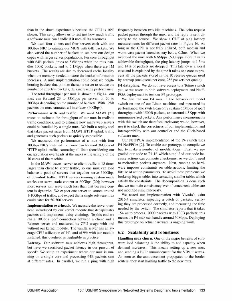
We plot the median and 99th percentile of client-measured flow completion as a function of time in fig-ure 19. The graph shows that adding servers drasticallyreduces both the median flow completion time and espe-cially the tail. The median drops from 10s when a singleserver is used, to 1s when six servers are used. The 99th
percentile also drops from 50-100s with one server to acouple of seconds with six servers. Notice the ten secondspikes in 99% FCT when muxes are killed: these are sub-flows that were handled by the failed mux, and they stallthe entire MPTCP connection until they timeout and theirpackets are reinjected on good subflows.
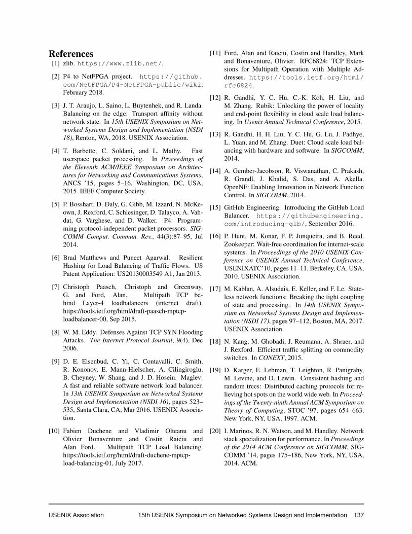
Figure 21 shows the cumulative number of packetssent by each server and we can clearly see how initiallyonly one server is active, another quickly follows andthen more servers join one minute apart. The graph alsoshows that Beamer does a good job spreading connectionsequally across all active servers.
Finally, we wanted to check that daisy chaining worksas described. We plot the number of daisy chained packetsby each server in Figure 22. Note the different unit on they axis (thousands of packets instead of millions): daisychaining not only works, but it is also quite cheap. Daisychaining forwards a total of 30 thousand packets, most ofwhich are ACKs (total size is around 200KB).
Siege did not report any failed connections, but thiscould be masked by MPTCP’s robustness to failures. Welooked at individual subflow statistics and found that no
subflows were reset; we did see numerous subflow time-outs triggered by mux failures, however these are wellmasked by MPTCP: when one subflow crossed a failedmux, its packets get resent on other working subflows.
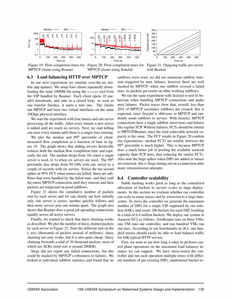
We ran the same experiment with Stateful to test its be-haviour when handling MPTCP connections and undermux failures. Packet traces show that, overall, less than20% of MPTCP secondary subflows are created; this isexpected, since Stateful is oblivious to MPTCP and ran-domly sends subflows to servers. With Stateful, MPTCPconnections have a single subflow most times and behavelike regular TCP. Without failures, FCTs should be similarto MPTCP/Beamer since the total achievable network ca-pacity is the same. The FCT results in Figure 20 confirmour expectations: median FCTs are similar, however the99th percentile is much higher. This is because MPTCPdoes a much better job of pooling the available networkcapacity than TCP does, thus reducing the outlier FCTs.Also note the huge spikes when DIPs are added or muxesare removed: this is Siege timing out on a connection aftermany retransmission attempts.
6.4 Controller scalabilityStable hashing works great as long as the centralized
allocation of buckets to servers scales to large deploy-ments. In this section we evaluate whether our controllercan scale to many muxes and by extension to a large data-center. To stress the controller we generate the maximumnumber of DIPs for a single VIP supported by our solu-tion (64K), and create 100 buckets for each DIP, resultingin a total of 6.4 million buckets. We deploy our system inAmazon EC2 as follows: ZooKeeper runs on three VMs,one VM runs our controller, and one hundred VMs runour mux. According to our benchmarks in §6.1, one hun-dred muxes should easily be able to load balance trafficfor 64K typical HTTP servers.
First, we want to see how long it takes to perform con-trol plane operations on the maximum load balancer in-stance we can support. We have stress-tested the con-troller and run each operation multiple times with differ-ent numbers of pre-existing DIPs, randomized bucket-to-
USENIX Association 15th USENIX Symposium on Networked Systems Design and Implementation 135

��������������������
���
�� ���� ���� ���� ���� ����
�������������
�����
����
��������
Figure 22: Packets daisy chained perserver.
# DIPs Add (sec) Rm (sec)1 0.63 0.5810 0.57 0.57100 0.69 0.67640 0.87 1.586400 6.9 2.2516000 8.1 3.232000 9.8 9.7
Figure 23: Duration of con-trol plane ops on the largestBeamer instance
0
20
40
60
80
100
64 128 256 512 1024 2048 4096 8192
CD
F (
%)
Latency (ms)
6.4K DIPs 16K DIPs 32K DIPs
Figure 24: Time to propagate a controllerupdate from ZooKeeper to all the muxes.
DIP assignments 2, and recorded the maximum comple-tion time. The results are provided in table 23, showingthat the Beamer controller performs large config changesin a few seconds.
Next, we measured the time it takes since the controllercommits a new generation until all muxes download andstart using it. Fig. 24 shows a CDF of the propaga-tion time as measured at the muxes for three large configchanges (adding 6.4K, 16K or 32K servers); the resultsshow that even for 32K servers, all muxes use the newdataplane rules in a few seconds. Smaller updates are in-stalled in tens to hundreds of milliseconds.
Finally, we note that all operations generated negligibleamounts of control traffic; the largest ones (the additionor removal of 32K DIPs) incurred less than 1GB of traffic(10MB per mux).
7 Related workAlmost all existing solutions for datacenter load bal-
ancing keep per-flow state at muxes. Software solutionsinclude Ananta [26], Maglev[9], IPVS[31] and GLB[15]while hardware ones include Duet [13] and SilkRoad[22]. Resilient hashing [6] takes a similar approach onswitches and routers to avoid the pitfalls of ECMP. To al-low scale in/out without affecting client traffic, statefuldesigns could use flow state migration, which is very ex-pensive: OpenNF [14] or Split Merge [28] offer migrationguarantees and strong consistency but at a steep perfor-mance cost (Kpps speeds).
A parallel effort to ours is Faild[3], a commercial state-less load balancer that works within a single L2 domainusing ARP rewriting; this reduces its applicability to smallclusters. Kablan et al.[17] propose to store per-flow statein a distributed key-value storage solution such as RAM-Cloud [25] instead of keeping it in memory; however itsperformance is limited to 4.6Mpps per box, eight timesslower than Beamer.
2Updates to the dataplane are stored in a compressed format and hav-ing randomized bucket assignments yields near-worst-case compressionratios.
Load balancing within a single OpenFlow switch hasbeen examined in [24, 32]. Orthogonal to existing loadbalancing solutions, Rubik[12] uses locality to reducebandwidth overhead of load balancing while Niagara [18]offers an SDN-based solution to improve network-widetraffic splitting using few OpenFlow rules.
Paasch et. al [7] discuss the problems posed by MPTCPtraffic to datacenter load balancers. Their analysis focuseson ensuring SYN(MPC) and SYN(JOIN) packets reachthe same server, and it assumes muxes keep per flow stateafter the initial decision has been made. Duchene et. al[10] propose to load balance secondary MPTCP subflowsby using IPv6 addresses; Beamer could easily implementthis solution if both the client and the datacenter have IPv6enabled and a working IPv6 path between them. Finally,Olteanu et al. propose [23] to load balance MPTCP trafficby encoding the server identifier in the TCP timestampoption; unfortunately this solution does not work if theclient does not support or enable timestamps, and supportsa smaller number of servers (8192) per VIP.
8 ConclusionsWe have presented Beamer, the first stateless
datacenter-scale load balancer solution that can handleboth TCP and Multipath TCP traffic. Beamer muxestreat TCP and MPTCP traffic uniformly, allowing themto reach speeds of 6Mpps per core and 33Mpps per box,twice faster than the fastest existing TCP load balancer,Maglev [9]. A Beamer mux can saturate four 10GbpsNICs with real HTTP uplink traffic using just 7 cores.
Daisy chaining enables Beamer to provide connectionaffinity despite DIP and mux failure, removal and addi-tion. In contrast to stateful designs, Beamer handles SYNflood attacks seamlessly.
Beamer is available as open-source software athttps://github.com/Beamer-LB.
AcknowledgementsThis work was partly funded by the SSICLOPS and
SUPERFLUIDITY H2020 projects.
136 15th USENIX Symposium on Networked Systems Design and Implementation USENIX Association
References[1] zlib. https://www.zlib.net/.
[2] P4 to NetFPGA project. https://github.com/NetFPGA/P4-NetFPGA-public/wiki,February 2018.
[3] J. T. Araujo, L. Saino, L. Buytenhek, and R. Landa.Balancing on the edge: Transport affinity withoutnetwork state. In 15th USENIX Symposium on Net-worked Systems Design and Implementation (NSDI18), Renton, WA, 2018. USENIX Association.
[4] T. Barbette, C. Soldani, and L. Mathy. Fastuserspace packet processing. In Proceedings ofthe Eleventh ACM/IEEE Symposium on Architec-tures for Networking and Communications Systems,ANCS ’15, pages 5–16, Washington, DC, USA,2015. IEEE Computer Society.
[5] P. Bosshart, D. Daly, G. Gibb, M. Izzard, N. McKe-own, J. Rexford, C. Schlesinger, D. Talayco, A. Vah-dat, G. Varghese, and D. Walker. P4: Program-ming protocol-independent packet processors. SIG-COMM Comput. Commun. Rev., 44(3):87–95, Jul2014.
[6] Brad Matthews and Puneet Agarwal. ResilientHashing for Load Balancing of Traffic Flows. USPatent Application: US20130003549 A1, Jan 2013.
[7] Christoph Paasch, Christoph and Greenway,G. and Ford, Alan. Multipath TCP be-hind Layer-4 loadbalancers (internet draft).https://tools.ietf.org/html/draft-paasch-mptcp-loadbalancer-00, Sep 2015.
[8] W. M. Eddy. Defenses Against TCP SYN FloodingAttacks. The Internet Protocol Journal, 9(4), Dec2006.
[9] D. E. Eisenbud, C. Yi, C. Contavalli, C. Smith,R. Kononov, E. Mann-Hielscher, A. Cilingiroglu,B. Cheyney, W. Shang, and J. D. Hosein. Maglev:A fast and reliable software network load balancer.In 13th USENIX Symposium on Networked SystemsDesign and Implementation (NSDI 16), pages 523–535, Santa Clara, CA, Mar 2016. USENIX Associa-tion.
[10] Fabien Duchene and Vladimir Olteanu andOlivier Bonaventure and Costin Raiciu andAlan Ford. Multipath TCP Load Balancing.https://tools.ietf.org/html/draft-duchene-mptcp-load-balancing-01, July 2017.
[11] Ford, Alan and Raiciu, Costin and Handley, Markand Bonaventure, Olivier. RFC6824: TCP Exten-sions for Multipath Operation with Multiple Ad-dresses. https://tools.ietf.org/html/rfc6824.
[12] R. Gandhi, Y. C. Hu, C.-K. Koh, H. Liu, andM. Zhang. Rubik: Unlocking the power of localityand end-point flexibility in cloud scale load balanc-ing. In Usenix Annual Technical Conference, 2015.
[13] R. Gandhi, H. H. Liu, Y. C. Hu, G. Lu, J. Padhye,L. Yuan, and M. Zhang. Duet: Cloud scale load bal-ancing with hardware and software. In SIGCOMM,2014.
[14] A. Gember-Jacobson, R. Viswanathan, C. Prakash,R. Grandl, J. Khalid, S. Das, and A. Akella.OpenNF: Enabling Innovation in Network FunctionControl. In SIGCOMM, 2014.
[15] GitHub Engineering. Introducing the GitHub LoadBalancer. https://githubengineering.com/introducing-glb/, September 2016.
[16] P. Hunt, M. Konar, F. P. Junqueira, and B. Reed.Zookeeper: Wait-free coordination for internet-scalesystems. In Proceedings of the 2010 USENIX Con-ference on USENIX Annual Technical Conference,USENIXATC’10, pages 11–11, Berkeley, CA, USA,2010. USENIX Association.
[17] M. Kablan, A. Alsudais, E. Keller, and F. Le. State-less network functions: Breaking the tight couplingof state and processing. In 14th USENIX Sympo-sium on Networked Systems Design and Implemen-tation (NSDI 17), pages 97–112, Boston, MA, 2017.USENIX Association.
[18] N. Kang, M. Ghobadi, J. Reumann, A. Shraer, andJ. Rexford. Efficient traffic splitting on commodityswitches. In CONEXT, 2015.
[19] D. Karger, E. Lehman, T. Leighton, R. Panigrahy,M. Levine, and D. Lewin. Consistent hashing andrandom trees: Distributed caching protocols for re-lieving hot spots on the world wide web. In Proceed-ings of the Twenty-ninth Annual ACM Symposium onTheory of Computing, STOC ’97, pages 654–663,New York, NY, USA, 1997. ACM.
[20] I. Marinos, R. N. Watson, and M. Handley. Networkstack specialization for performance. In Proceedingsof the 2014 ACM Conference on SIGCOMM, SIG-COMM ’14, pages 175–186, New York, NY, USA,2014. ACM.
USENIX Association 15th USENIX Symposium on Networked Systems Design and Implementation 137

[21] MAWI Working Group Traffic Archive. http://mawi.wide.ad.jp/mawi/.
[22] R. Miao, H. Zeng, C. Kim, J. Lee, and M. Yu.Silkroad: Making stateful layer-4 load balancing fastand cheap using switching asics. In Proceedings ofthe Conference of the ACM Special Interest Groupon Data Communication, SIGCOMM ’17, pages15–28, New York, NY, USA, 2017. ACM.
[23] V. Olteanu and C. Raiciu. Datacenter scale load bal-ancing for multipath transport. In Proceedings ofthe 2016 Workshop on Hot Topics in Middleboxesand Network Function Virtualization, HotMIddle-box ’16, pages 20–25, New York, NY, USA, 2016.ACM.
[24] V. A. Olteanu, F. Huici, and C. Raiciu. Lost in net-work address translation: Lessons from scaling theworld’s simplest middlebox. In Proceedings of the2015 ACM SIGCOMM Workshop on Hot Topics inMiddleboxes and Network Function Virtualization,HotMiddlebox ’15, pages 19–24, New York, NY,USA, 2015. ACM.
[25] D. Ongaro, S. M. Rumble, R. Stutsman, J. Ouster-hout, and M. Rosenblum. Fast crash recovery inramcloud. In Proceedings of the Twenty-Third ACMSymposium on Operating Systems Principles, SOSP’11, pages 29–41, New York, NY, USA, 2011. ACM.
[26] P. Patel, D. Bansal, L. Yuan, A. Murthy, A. Green-berg, D. A. Maltz, R. Kern, H. Kumar, M. Zikos,H. Wu, C. Kim, and N. Karri. Ananta: Cloud scaleload balancing. In SIGCOMM, 2013.
[27] C. Raiciu, C. Paasch, S. Barre, A. Ford, M. Honda,F. Duchene, O. Bonaventure, and M. Handley. Howhard can it be? designing and implementing a de-ployable multipath TCP. In NSDI, 2012.
[28] S. Rajagopalan, D. Williams, H. Jamjoom, andA. Warfield. Split/merge: System support for elasticexecution in virtual middleboxes. In NSDI, 2013.
[29] L. Rizzo. netmap: A novel framework for fast packeti/o. In Proc. USENIX Annual Technical Conference,2012.
[30] D. G. Thaler and C. V. Ravishankar. Using name-based mappings to increase hit rates. IEEE/ACMTrans. Netw., 6(1):1–14, Feb 1998.
[31] The Linux Foundation. The IP VirtualServer Netfilter module for kernel 2.6.
http : / / www . linuxvirtualserver .org/software/ipvs.html, February 2011.
[32] R. Wang, D. Butnariu, and J. Rexford. Openflow-based server load balancing gone wild. In HotICE,2011.
AppendixA1. Defragmentation
There is a three-way trade-off between load balancing,fragmentation and churn. Beamer prioritizes load balanc-ing, ensuring near-perfect balancing at all times. Thismeans that we can either end up with fragmented bucketranges assigned to servers (which will increase dataplanematching costs, especially for hardware dataplanes suchas P4) or move buckets to reduce fragmentation but createdaisy chaining traffic in the meantime.
Defragmentation is therefore necessary to ensureservers get a contiguous range of buckets, as this will re-duce the number of rules needed in the mux dataplane.Beamer implements an algorithm that reduces fragmen-tation progressively, while keeping daisy-chaining costssmall. The algorithm has two parameters: a target frag-mentation rate (fr ≥ 1, target average number of rulesper DIP), and bmax, the maximum number of bucketsthat can be moved per server, per iteration.
The defragmentation algorithm has two phases: it firstselects a target mapping and then it iteratively moves to-wards this target. The target mapping is computed when-ever the DIP set changes, and this triggers a second im-plementation phase that includes a number of iterationswhere at most bmax buckets per server are moved in eachiteration; iterations are spread in time (one iteration every4 minutes). The second phase stops whenever the targetdefragmentation rate is reached. While heuristic, the al-gorithm performs really well in practice.
The target mapping is computed greedily: starting atbucket offset 0, the controller selects the server whichcan take over a contiguous range while causing the leastamount of churn. After every step, the offset is then incre-mented past the newly-allocated range.
start = 0while (start < #buckets) {select DIP A s.t. churn of assigning A
at position start is minimized.target(A) = {start, start+#buckets(A)}start += #buckets(A)
}
During each iteration of the second stage (pseudocodebelow), the controller performs a subset of the realloca-tions prescribed by the target mapping. It performs no
138 15th USENIX Symposium on Networked Systems Design and Implementation USENIX Association
Hashing algo. Imbalance Min. dataplane rules
Server churn1% 5%
Consistent[19] 2.27 9K 0 0Maglev[9] 1.01 65K 2.3% 3.3%Stable Hashing 1.01 1K 0 0
Table 1: Hashing comparison, N=1000 and B=65537
more than bmax reallocations per DIP, while keeping thenumber of buckets constant for each DIP. (I.e. the numberof buckets allocated to each DIP is the same as the numberof buckets allocated away from it.)
let G = (V, E) be a directed multigraph, wherevertices are DIPs and edges are bucketreassignments
for each DIP in VDIP.budget = bmax
while (G.has_cycles) {select cycle Cfor each realloc in C.edges {
perform(realloc)E.remove(realloc)
}for each DIP in C.vertices {
DIP.budget -= 1if (DIP.budget == 0)
V.remove(DIP)}
}
A.2 Stable hashing evaluationTable 1 shows the performance of Stable hashing
against our implementations of the classical consistenthashing algorithm [19] and Maglev [9]. We used 1000servers and 65537 buckets (the params are from the Ma-glev paper, §5.3, for fair comparison). We first measuredthe imbalance—the ratio between the maximum and av-erage load—finding that Maglev and Stable have near-perfect load balancing, while Consistent hashing placestwice more load on one unlucky server.
We next computed the minimum number of range ruleswe need to use in a hardware data plane to perform match-ing: algorithms that assign consecutive buckets to thesame server will utilize fewer rules and are better. Thisis the case for Stable, where we only need one rule perserver; Maglev, in comparison, needs as many rules asbuckets, two orders of magnitude more than Stable. Con-sistent falls somewhere in the middle. Finally, we lookedat the number of “innocent” connections that are disruptedwhen we remove a number of nodes; both Consistent andStable have no collateral damage, while Maglev breaks2.3%-3.3% of ongoing connections.
A.3 Defragmentation evaluationStable hashing can enable very cheap hardware imple-
mentation with one rule per server, but this is only the
0
20
40
60
80
100
0 1 2 3 4 5 6 7
Fra
gm
en
tatio
n
Total buckets migrated (million)
Figure 25: Defragmentating bucket-to-DIP assignmentsto reduce the number of data plane rules.
case when all the buckets assigned to one DIP are contigu-ous. As servers come and go, even a perfect distributioncan end up fragmenting the buckets, with each server incharge of many small ranges; this would require propor-tionally more rules to implement in hardware.
To avoid this effect, especially for hardware deploy-ments, we can use the defragmentation described above:when the average number of rules per server increases be-yond a given threshold, the defragmentation algorithm isinvoked, reassigning buckets to remove fragmentation asdescribed in §4.5.
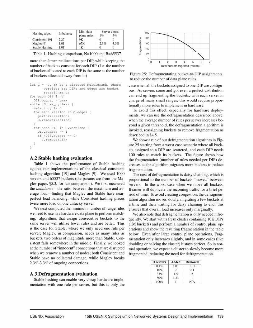
We show a run of our defragmentation algorithm in Fig-ure 25 starting from a worst case scenario where all buck-ets assigned to a DIP are scattered, and each DIP needs100 rules to match its buckets. The figure shows howthe fragmentation (number of rules needed per DIP) de-creases as the algorithm migrates more buckets to reducefragmentation.
The cost of defragmentation is daisy chaining, which isproportional to the number of buckets “moved” betweenservers. In the worst case when we move all buckets,Beamer will duplicate the incoming traffic for a brief pe-riod of time. To avoid creating congestion, the defragmen-tation algorithm moves slowly, migrating a few buckets ata time and then waiting for daisy chaining to end; thisensures that overall load increases only marginally.
We also note that defragmentation is only needed infre-quently. We start with a fresh cluster containing 10K DIPs(1M buckets) and perform a number of control plane op-erations and show the resulting fragmentation in the tablebelow. Even after large control plane operations, Frag-mentation only increases slightly, and in some cases (likedoubling or halving the cluster) it stays perfect. So in nor-mal operation, we expect a cluster to slowly become morefragmented, reducing the need for defragmentation.
# servers Added Removed0.1% 1.01 1.0110% 2 2.133% 1.5 250% 1.33 1100% 1 N/A
USENIX Association 15th USENIX Symposium on Networked Systems Design and Implementation 139