state of mn bim guidelinev2 · new version of this document. ... record model should contain...
TRANSCRIPT

STATE OF MINNESOTA
BIM GUIDELINE
State of Minnesota’s Faci l i t ies Administration Data Capture Plan
January 2014

TABLE OF CONTENTS
BUILDING INFORMATION MODELING (BIM)....................................................................................... 1
PURPOSE OF THIS GUIDE ....................................................................................................................... 1
STATE’S VISION FOR BIM ........................................................................................................ 1
GOALS OF BIM STANDARDIZATION ..................................................................................... 2
AUTHORING SOFTWARE ....................................................................................................................... 2
MODEL + DATA OWNERSHIP................................................................................................................ 2
BIM PROJECT MANAGEMENT .............................................................................................................. 2
BIM MANAGER ........................................................................................................................ 2
DISCIPLINE/TRADE COORDINATION .................................................................................... 2
BIM IMPLEMENTATION PLAN (BIP) ........................................................................................ 3
RECORD MODEL ..................................................................................................................... 3
AUTHORING SOFTWARE ....................................................................................................................... 4
SOFTWARE REQUIREMENTS ................................................................................................... 4
STATE SPACE + DATA STANDARDS ...................................................................................................... 4
SPACE MEASUREMENT ........................................................................................................... 4
SPACE TYPES + MEASUREMENT METHODOLOGY .............................................................. 4
ROOM NUMBERING CONVENTIONS ................................................................................... 5
ASSET DATA STANDARDS ....................................................................................................... 5
SHARED PARAMETERS ............................................................................................................ 6
UNIFORMAT + OMNICLASS CLASSIFICATION .................................................................................... 7
MODEL CONTINUITY .............................................................................................................................. 7
MODEL GRANULARITY .......................................................................................................................... 7
LEVEL OF DEVELOPMENT (LOD) .......................................................................................................... 7
GENERAL INFORMATION
REQUIREMENTS
DELIVERABLES

BIM IMPLEMENTATION PLAN (BIP) ....................................................................................................... 8
PHASING + INFORMATION EXCHANGE ............................................................................................. 8
SUBMISSION REQUIREMENTS ................................................................................................................ 9
FILE MANAGEMENT ................................................................................................................ 9
HAND OVERS........................................................................................................................... 9
GLOSSARY ............................................................................................................................................ 10
DEFINITIONS AND ACRONYMS ................................................................................................. 10
APPENDIX .............................................................................................................................................. 12
EXHIBIT A: BIM USES .................................................................................................................... 13
EXHIBIT B: BIM IMPLEMENTATION PLAN ................................................................................... 20
EXHIBIT C: EQUIPMENT ASSETS .................................................................................................. 30
EXHIBIT D: EQUIPMENT ASSET DETAILS ..................................................................................... 31
EXHIBIT E: ASSETS DATA MAPPING MATRIX ............................................................................. 35
EXHIBIT E: OPERATIONS + MAINTENANCE SUPPORT INFORMATION ................................... 36
EXHIBIT F: REVIT SHARED PARAMETERS .................................................................................... 37
EXHIBIT G: REFERENCES + RESOURCES .................................................................................... 38
GLOSSARY + APPENDIX

State of Minnesota BIM Guideline 1
BUILDING INFORMATION MODELING (BIM)
What is BIM? Who’s using BIM? What are the benefits of BIM?
Building Information Modeling (BIM) is a collaborative effort involving the creation and
management of digital, 3D building models and their associated data. BIM and Facility
Management (FM) systems form a bi-directional link which allows for immediate
information exchange, enhanced data accuracy, and increased productivity
BIM allows various stakeholders to participate in the building construction and
management process beginning at design inception and extending all the way to facilities
management. As a project develops, detailed asset information is tracked and stored for
future reference. BIM can accomplish a wide variety of objectives depending upon the
goal and scope of a given project.
Building Information Models (BIMs) are multidimensional; they function in 3D, 4D (time) and
5D(cost). BIMs can be assigned a nearly unlimited range of visual and non-visual building
related information. The unique functionality of BIM makes it a very effective
interdisciplinary coordination tool. It provides building stakeholders the benefit of seeing a
building and its components in a virtual environment prior to physical construction. For
additional information on the multitude of BIM applications please see Exhibit A: BIM Uses.
Benefits of BIM include but are not limited to:
• A collaborative and integrated approach to design.
• Use of 2D and 3D visualization of the building for marketing materials, and use of
4D (scheduling) and 5D (estimating) process modeling for construction
sequencing and planning.
• Faster project delivery through design practicality, integrity and real-time
estimating
• Project waste reduction through exact quantity take-offs, model schedule
scenarios and site logistic planning.
• Increased construction and public safety through the review of complex
structural details and crowd/fire modeling.
• Lifecycle asset management including information on product installation,
warranties, serial numbers and preventative maintenance.
PURPOSE OF THIS GUIDE
State’s Vision for BIM
The following document is provided to assist in the development of Integrated Lifecycle
Management (ILM) strategies through Building Information Modeling (BIM) and Data
Management.
The Building Information Modeling (BIM) Guideline represents a BIM pilot program and
lifecycle data capture effort by the State of Minnesota. This guideline reflects an effort to
enhance the technologies and processes employed by the State and its participating
Agencies in the realms of construction and facilities management. The State of Minnesota
is committed to adopting BIM as effectively and efficiently as possible.
The State of Minnesota has issued these instructions to aid in the implementation of
current and future BIM projects.
GENERAL INFORMATION

State of Minnesota BIM Guideline 2
Goals of BIM Standardization
The goal is to promote facility management standards and practices by gathering
relevant data and documentation from the Architectural, Engineering and Construction
(AEC) team for a given project. BIM allows for earlier and more accurate data collection
during the construction process and assures that facility information is available in the
web-enabled real property management system, Archibus. The State of Minnesota plans
to integrate the data present in the Record BIM Model into its communal databases while
also employing BIM as a tool for effective construction project management.
Objectives:
• Establish an environment to collaborate and coordinate BIM data and metadata
for the life of the project.
• Transfer modeling content from one party to another
• Prepare accurate construction documents derived from the model
• Verify equipment asset attribute data in the model
• Integrate model metadata into the current web-enabled real property
management system
• Track manufacturer, commissioning, and maintenance records
• Develop a Record BIM Model for integration into a facility management system
• Control and map metadata into the real property management system
AUTHORING SOFTWARE
The State of Minnesota acknowledges that there are numerous BIM authoring software
programs available, but requires all record BIM models to be submitted with Autodesk
Revit version 2013. This requirement is due in part to the statewide integration of the
facility management software, Archibus.
MODEL + DATA OWNERSHIP
The State of Minnesota retains ownership of all BIMs, Building Data, and electronic CAD
files, including, but not limited to, the designs, ideas, and inventions developed within the
project. The State of Minnesota shall have ownership of all contents within the BIMs from
schematic design to project delivery.
BIM PROJECT MANAGEMENT
BIM Manager
The BIM Manager shall act as the primary contact with the State of Minnesota for all BIM
related activity on a given project. This individual will have the necessary experience and
knowledge required for successful BIM implementation as it relates to the scope and
complexity of the given project.
General Responsibilities:
• Assures development and compliance with State of Minnesota BIM Guidelines.
• Overall Responsibility for the coordination, creation, and implementation of BIM
during design and Construction.
• Coordinates and Manages BIM related meetings with Lead BIM developers.
• Manage and maintain all creation of BIM content.
Discipline/Trade Coordination
All parties involved in the creation of a BIM shall communicate changes to the record file
in real time. Each discipline or team should elect a BIM Coordinator to serve as a lead
technician and communicator to ensure that information is shared in a transparent and

State of Minnesota BIM Guideline 3
timely manner. BIM is a multidisciplinary effort and it is therefore imperative that project
teams communicate and coordinate effectively.
BIM Implementation Plan (BIP)
The BIM Implementation Plan addresses the targeted BIM Uses on the project, delineates
roles and responsibilities of each company. The BIP defines the detail and scope of
information to be modeled and shared, as well as relevant processes, team setup, and
rules of engagement. This document is intended to be complimentary to the State of
Minnesota BIM Guideline. At any point in time, this document along with the Level of
Development (LOD) Matrix, are the governing documents that determine all aspects of
BIM Implementations on the project. Changes to the BIM Implementation Plan will be
incorporated only after owner and project team reach consensus and will be shared as a
new version of this document.
Record Model
The Record Model shall be delivered to the State of Minnesota to depict an accurate
representation of the physical conditions, environment, and assets of a facility. The
Record Model should contain information relating to the main Architectural and MEP
elements in addition to information including equipment and space planning systems to
be used for building maintenance and operations. The Record Model contains a true
depiction of space and equipment with information such as finishes, serial numbers,
warranties and manufacturer of components in the building. The AEC Team shall submit
a negotiated LOD Record Revit Model to the State of Minnesota for their Lifecycle
Operations and Maintenance process.

State of Minnesota BIM Guideline 4
AUTHORING SOFTWARE
Software requirements
The State of Minnesota requires all Record BIM models to be submitted with Autodesk
Revit version 2013.
STATE SPACE + DATA STANDARDS
Space Measurement
The State of Minnesota has a standard method of measuring Room Square Footage. A
designated party shall be responsible for setting up Area Plans and Area Boundary lines to
track tenant areas. The designated party will be responsible for making any updates to
these areas until the Record Model is complete. No Additional Room data is required by
the Design or Construction Team for Lifecycle Management. Existing parameters at the
Room’s Instance Level will provide the necessary data. This method is summarized in the
table below:
Space Types + Measurement Methodology
Source: State of Minnesota Space Management Background Data Formats & Standards
Space Type Definition Comments
Exterior Gross
The Exterior Gross is measured by drawing an area
boundary line tracing the outside surface of the
exterior wall.
Not used in remaining area
calculations
Interior Gross* The Interior Gross is measured by drawing a closed area
boundary line along the inside finished surface of the
exterior wall. If more than 50% of the vertical height of
an exterior wall is glass, the area boundary line is drawn
along the inside face of the glass.
Area boundary lines to inside
face of the building
Vertical
Penetrations*
A Vertical Penetration is measured by drawing area
boundary lines around the outside finished surface of its
enclosing walls. When the Vertical Penetration is
adjacent to another Vertical Penetration, the space is
measured to the centerline of the connecting wall.
Any vertical penetration is a
location on a floor plate
where no floor exists. Space
such as stairwells, elevator
shafts, mechanical shafts,
plumbing chases, atriums, etc
Rentable Area Internal Gross Area - Tot Vert Pen Area = Rentable Area Calculation
Service Area*
Service area is measured to the outside finished
surface of its enclosed walls, except when adjacent to
a Vertical Penetration. When adjacent to a Vertical
Penetration, the Service Area is measured to the inside
finished surface of its enclosed walls. When service
areas are adjacent to other service areas, the space is
measured to the centerline of the connecting wall.
Space that supports building
functions such as mechanical
rooms, utility closets, janitor
closets, and docks or is
available to all persons in the
building such as corridors and
restrooms
Useable Area Rentable Area – Total Service Area = Usable Area Calculation
Groups* Group areas are measured by drawing an area
boundary line around the perimeter of offices,
workstations and internal circulation areas that are
occupied by a single cost center or division. Where
workspaces are allocated to different cost centers or
Referred to as Group Area or
Chargeable Area
Groups may be assigned to a
REQUIREMENTS

State of Minnesota BIM Guideline 5
divisions, the group line is drawn down the centerline of
the wall dividing the allocated areas. Group areas are
drawn along the previously drawn area boundary lines
for interior gross, vertical penetrations, and
service/common areas. No deductions are made for
columns, pilasters, or other projections necessary to the
building or for interior walls. The sum of all group areas
on a floor equals the useable area of a floor. Group
areas should be drawn around unallocated space as
well, to insure accuracy by identifying Remaining Area.
Division and a Cost Center
The remaining area shall be
equal to “0” with a
tolerance of +/- one (1)
square foot.
Remaining Area Usable Area – The sum of the group areas on a floor =
Remaining Area
Calculation
DWS* Dead Wall Space is any wall measuring a minimum of
12” thick with an area of four or more square feet
or any column or pilaster whose area is equal to or
greater than four square feet.
Dead Wall Space is
subtracted from a group to
determine their useable area.
RPMN Usable Area Rentable Area – Service – DWS = RPMN Usable Area Calculation
* Indicates Space Types used in calculations
Room Numbering Conventions
The State’s Room numbers will be assigned to the Room Number Parameter in Revit for
each individual room. This process gives the space a Unique Identifier understood by the
State of Minnesota while also allowing the developed space to be connected to
complex space standards inside the State’s Real Property Management System. This
serves as the Primary Connector for Room Data between Revit and the System.
Asset Data Standards
Asset Management
Tracking specific Assets during Design & Construction aids the State of Minnesota in
more efficient maintenance and operation procedures of a facility. Having data in
the model early allows the FM team to start planning for building start up and tracking
of building operations, instead of spending time on data entry or searching for O&M
documentation. The Shared Parameter file will provide fields to track this data on
equipment during the Construction process. All asset naming and definition standards
for data capture during construction can be found in Exhibit C-Equipment Assets and
Exhibit D-Equipment Asset Details.
The Mark field in Revit is to be coordinated with the State’s FM Equipment Use field. This
creates a relationship between the names of unique equipment and their associated
equipment tags. The Equipment Code serves as the Primary Connecter for Equipment
Data between Revit and the State’s Real Property Management System, which will be
the barcode number authored into the model during Construction by the
Construction Manager/Contractor or Sub-trade.
Types of Model Elements
Model elements will be derived from the following sources to include specific Shared
Parameters for Room and Equipment:
Manufacturer’s Model Elements
Elements created by and acquired from manufacturers often have more
information than is prudent to keep in the model; the level of detail as defined in
the LOD Matrix should be retained for the design element. However, embedded
performance data shall remain for analysis and specification purposes.

State of Minnesota BIM Guideline 6
Custom Created Model Elements
Custom model elements that are created must utilize appropriate BIM Authoring
tool templates. Custom models components need to be assigned as a part and
part of a family or group.
Shared Parameters
The required Shared Parameters can be issued by the State of Minnesota as a Revit
Template file so those Instance Parameters can be transferred to the Design model.
Facilities Data will be entered into these fields in the Construction model and eventually
be passed to the Record Model. These Shared Parameters will exist at the Instance Level,
not the Family Level. If Parameters requested by the State of Minnesota exist at the
Family Level for the Manufacture’s Elements or Custom Elements, that data will have to
be duplicated at the Instance Level as well. Please refer to Exhibit E: Asset Data Mapping
Matrix for the responsibility of populating the Shared Parameters data.

State of Minnesota BIM Guideline 7
UNIFORMAT + OMNICLASS CLASSIFICATION
The State of Minnesota classifies and organizes its building components and assets
according to the UniFormat and OmniClass systems as defined by the Construction
Specifications Institute or CSI. UniFormat is a standard for classifying building
specifications based upon system function rather than construction materials or methods.
The OmniClass Construction Classification System or OCCS organizes information from
other extant systems including UniFormat and MasterFormat into normalized tables.
UniFormat 2010 and OmniClass 2010 as released by the CSI should be referenced when
classifying objects within a Building Information Model.
MODEL CONTINUITY
In order to ensure model continuity, the State of Minnesota requires that all models be
developed using exclusively object based elements. This means that elements such as
windows, doors, floors and roofs shall be associated with parametric information and will
not exist as simple geometry. Continuity ensures consistency in the creation and
development of a BIM, allowing a single model to be utilized from the conceptual design
phase all the way to building operation and maintenance.
MODEL GRANULARITY
Model granularity determines the detail or accuracy with which geometry is represented
within a specified Building information Model. The level of development will vary by
project and for any given object. It is possible with a low granularity that a BIM will not
accurately communicate form, and in turn, design intent; this is important to keep in mind
when determining the goal or purpose of a BIM.
It is generally accepted that objects measuring less than 6” x 6” x 6” should not be
modeled, but rather represented as a node and assigned the appropriate parametric
information. This can be overlooked if a significant goal of a BIM is to provide design
visuals or renderings.
LEVEL OF DEVELOPMENT (LOD)
Level of Development articulates the extent to which model elements are developed
and their level of reliability. Each LOD prescribes minimum content requirements; these
requirements specify detail of representation and attached content. Each model
element should only be considered reliable to its prescribed degree. This agreed upon
LOD will provide a framework and standard for all parties creating BIMs.
The Level of Development definitions as outlined in the AIA Document E202-2008, Building
Information Protocol, are below.
LOD 100
The Model Element may be graphically represented in the Model with a symbol or
other generic representation, but does not satisfy the requirements for LOD 200.
Information related to the Model Element (i.e., cost per square foot, tonnage of HVAC,
etc.) can be derived from other Model Elements.
DELIVERABLES

State of Minnesota BIM Guideline 8
LOD 200
The Model Element is graphically represented within the Model as a generic system,
object, or assembly with approximate quantities, size, shape, location, and orientation.
Non-graphic information may also be attached to the Model Element.
LOD 300
The Model Element is graphically represented within the Model as a specific system,
object or assembly in terms of quantity, size, shape, location, and orientation. Non-
graphic information may also be attached to the Model Element.
LOD 400
The Model Element is graphically represented within the Model as a specific system,
object or assembly in terms of size, shape, location, quantity, and orientation with
detailing, fabrication, assembly, and installation information. Non-graphic information
may also be attached to the Model Element.
LOD 500
The Model Element is a field verified representation in terms of size, shape, location,
quantity, and orientation. Non-graphic information may also be attached to the
Model Elements.
Equipment LOD Specifications
For more information, reference BIMForum’s LOD Specifications Document as sited by
AIA E202-2008. This document follows current AIA LOD conventions, provides graphic
representations and can be downloaded at bimforum.org/lod
BIM IMPLEMENTATION PLAN (BIP)
The State of Minnesota requires a BIM Implementation Plan (BIP) to be completed after a
contract has been awarded for any project utilizing BIM technology.
This document is meant to establish goals and coordination efforts of appropriate
stakeholders, while outlining the processes, work flows, and management of the BIM. This
document is intended to be complimentary to the State of Minnesota BIM Guideline.
The State of Minnesota BIM Guideline defines the expectations that the State has for the
final Record Model and data tracking. The Record Model and data tracking will be a
collaborative effort between the Design and Construction teams and their consultants.
The BIM Implementation Plan addresses the targeted BIM uses on the project, delineates
roles and responsibilities of each company, and defines the detail and scope of
information to be modeled and shared. Additionally, the BIP defines relevant processes,
team setup, rules of engagement, and supporting software.
At any point in time during the project, this document along with the Level of
Development Matrix (Exhibit E: Asset Data Mapping Matrix) is the governing document
that determines all aspects of the BIM. Changes to the BIM Implementation Plan will be
incorporated only after owner and project team consensus and will be shared as a
revised version to the document. See Exhibit B: BIM Implementation Plan
PHASING + INFORMATION EXCHANGE
There is not necessarily a direct relationship between a BIM’s LOD and traditional design
or construction phases as these systems may develop at differing rates. Information
exchanges should be agreed upon by all parties and include BIM development
milestones defined in the project’s BIM Implementation Plan. These milestones should
contain clear objectives, target dates and responsible parties.

State of Minnesota BIM Guideline 9
SUBMISSION REQUIREMENTS
File Management
Models may be separated by disciplines for design and construction coordination
throughout the construction process, but must ultimately be federated as a Record Revit
Model.
The Record Model should follow the file naming format below. The first three [3]
underscores (_) are used just to separate the section fields for explanation. The file names
shall consist of three [3] distinct State of Minnesota sections hyphenated by the discipline
and the date issued to the State.
Example Fields: Agency Code Site Code Building ID-Discipline_Published Date.xxx
Final Construction Model Convention:
As-Built Model: G02310100-AsBuilt_YYYYMMDD.nwd
Final Record Model Convention:
Architectural Model: G02310100-ARCH_YYYYMMDD.rvt
MEP: G02310100-MEP_YYYYMMDD.rvt
Structural Models: G02310100-STRL_YYYYMMDD.rvt
*If a Core/Shell and Interiors model both are developed for this Project please contact
the State for further direction. In most cases this would just be an additional Architectural
model listed as an “Interiors” model in the model naming structure above.
Hand Overs
3D Model files required:
Record Model
A final record model is to be delivered to the State of Minnesota depicting a
representation of the physical conditions, environment, and assets of a facility. The
Record Model should contain information relating to the main Architectural and MEP
elements in addition to information including equipment and space planning systems
to be used for maintenance and operations. The Record Model contains a depiction
of space and equipment with information such as finishes, serial numbers, warranties
and manufacturer of components in the building. The AEC Team shall submit a
Record Revit Model of a predetermined LOD to the State of Minnesota for their
Lifecycle Operations and Maintenance process.
2D Model files required
Operations + Maintenance Support Information (OMSI)
[The OMSI is in the scope of work of the Contractor and/or Commissioning Agent]
OMSI provides key information produced during the design, construction of new
facility acquisition. The OMSI Scope of Work helps ensure that virtually all as-built
architectural/engineering, technical product and system information will be available
in a standardized, user-friendly format for use over the lifecycle of the facility. The
purpose of the work is to provide OMSI manuals that contain detailed, as-built
information that describes the efficient, economical and safe operation,
maintenance, and repair of the facility. The OMSI manuals are to be factual, concise,
comprehensive and formatted to be easily used by operation and maintenance
personnel. Descriptive matter and theory must include technical details that are
essential for a comprehensive understanding of the operation, maintenance and
repair of the system. The Construction Manager/Contractor shall ensure that OMSI
manuals reflect changes to systems and equipment made during construction and
prepared as outlined in Exhibit F-Operations + Maintenance Support Information.

State of Minnesota BIM Guideline 10
DEFINITIONS + ACRONYMS
AEC
Architectural/Engineering/Construction Team
ARCHIBUS
Software application used for Space Planning and Facilities Maintenance
As-Built Documents
As-built documents are the collection electronic drawings or of paper drawings from the
Construction Manager/Contractor that contain mark-ups, annotations, and comments
about changes that have been made to the Contract Documents during the construction
phase.
Building Information Modeling (BIM)
An integrated process aimed at providing coordinated, reliable information about a
building project throughout different project phases—from design through construction
and into operations. BIM gives architects, engineers, builders, and owners a clear overall
vision of the project—to help them make better decisions faster, improve quality, and
increase profitability of the project.
Construction Documents
The Construction Documents are a set of Drawings, that along with the Specifications,
Addenda, Construction Change Directives, Change Orders or other written amendment
or orders make up the set of documents that includes all pertinent information required for
the contractor to price and build the project.
Construction Model
The model used to simulate and analyze the construction of a building.
Design Team
The Design Team is considered to be the Architect and all of the consultants that provide
design services for a project. These design services can be rendered at any time during
the project.
Design Model
The model used to communicate the design intent of a building.
BIM Implementation Plan (BIP)
BIM Implementation Plan defines BIM roles and responsibilities for Lifecycle Management
and Facilities Management data collection during Construction for a project issued.
Integrated Lifecycle Management (ILM)
A management process that improves collaboration and optimizes efficiency between
the AEC team and Owner through standardization and refinement of business structures
and facility practices into a process that collaboratively optimizes efficiency through all
phases of design, fabrication, construction and lifecycle management.
LOD
Level of Development
MEP
Mechanical, Electrical and Plumbing. MEP/FP is Mechanical, Electrical, Plumbing and Fire
Protection.
GLOSSARY

State of Minnesota BIM Guideline 11
BIM/Model Manager(s)
The project team member(s) responsible for managing the collaboration and sharing of
electronic files during the project. Model managers are also responsible for maintaining
the integrity of BIM models, which can include gathering, linking, and uploading updated
models.
Metadata
The term refers to "data about data". For this document it refers to individual instances of
application data, the data content, or “content about content". This content can be
authored in a field, stored and managed in one database and transfer to yet another
database.
O&M
Operations and Maintenance
OMSI
Operations and Maintenance Support Information
Record Model
Model containing all Contractual and As-Built conditions used to depict an accurate
representation of the physical conditions, environment, and assets of a facility. The Record
Model contains information relating to the main architectural, structural, and MEP
elements, coordinated with the As-Built conditions and Sub-contractor models. It is the
culmination of all the BIM Modeling throughout the project, including Operation,
Maintenance, and Asset data from the As-Built model. A Record Model is the further
development of the Design Model in the Authoring Software Platform for use by the Owner
and Facility Management Team. (Also see Section 4.1)
Record Documents
The production of Record Documents is the capturing of the As-Built Documents
annotation, comments, and mark-ups in drawing format. This may not include the
updating of any models as done purely for 2D documentation and are typically delivered
in electronic format.
RVT
An .RVT file is a Revit native file type. It is also the deliverable file format for all projects. This
includes all of the Design Team’s models.
Schematics
Similar to a Single Line Diagram, a Schematic Diagram illustrates the inter-relationship of
components, but incorporates more of a spatial context of the elements, i.e. locations.
Generally these are not to scale.

State of Minnesota BIM Guideline 12
EXHIBIT A: BIM USES The following document is provided to assist all project stakeholders understand the multitude
of ways they may leverage BIM technologies depending on their needs. This section highlights
various applications of BIM for each phase of a project.
EXHIBIT B: BIM IMPLEMENTATION PLAN (BIP) The following document is provided to assist in the development of the goals and coordination
efforts, as well as outline the processes, work flows, and management of the BIM. This
document is intended to be complimentary to the State of Minnesota BIM Guideline.
EXHIBIT C: EQUIPMENT ASSETS The following document is provided to highlight which Equipment Assets are to be tracked for
the State of Minnesota. Each project shall determine the required assets to track. Asset details
will be collected on the Equipment Assets determined by the project team.
EXHIBIT D: EQUIPMENT ASSET DETAILS This document lists the metadata parameters to be collected and tracked for all Assets listed in
Exhibit C: Equipment Assets and includes the fields to be collected. Individual fields listed in this
Exhibit document reside in the State of Minnesota Revit Template as Instance Parameters.
EXHIBIT E: ASSETS DATA MAPPING MATRIX This document governs the roles and responsibilities of all BIM stakeholders for capturing asset
data throughout the duration of the project.
EXHIBIT F: OPERATIONS + MAINTENANCE SUPPORT INFORMATION
The following exhibit contains OMSI information which should be coordinated with the
Equipment being tracked. The OMSI should be provided as PDF files.
EXHIBIT G: REVIT SHARED PARAMETERS
This is an electronic file named State of Minnesota ARCHIBUS Shared Parameters File Template.
Use this Revit .rte file to transfer Project Standards from the Template File to the Revit MEP
Design Model, Revit MEP Construction Model and the Record Revit MEP Model.
EXHIBIT H: REFERENCES + SOURCES
This exhibit is an overview of supplementary information, resources and references used in the
State of Minnesota BIM Guideline.
APPENDIX

State of Minnesota BIM Guideline 13
SCHEMATIC DESIGN ............................................................................................................................ 14
Existing Conditions Modeling ............................................................................................. 14
Cost Estimation ..................................................................................................................... 14
Phase Planning ..................................................................................................................... 14
Programming ........................................................................................................................ 14
Site Analysis ........................................................................................................................... 14
Design Review ...................................................................................................................... 14
DESIGN DEVELOPMENT ...................................................................................................................... 15
Design Authoring ................................................................................................................. 15
Structural Analysis ................................................................................................................ 15
Lighting Analysis ................................................................................................................... 15
Energy Analysis ..................................................................................................................... 15
Mechanical Analysis............................................................................................................ 16
Engineering Analysis ............................................................................................................ 16
Sustainability Guideline Evaluation ................................................................................... 16
Code Analysis ....................................................................................................................... 16
CONSTRUCTION DOCUMENTATION ................................................................................................. 16
3D Coordination/Clash Detection .................................................................................... 16
Site Utilization Planning ........................................................................................................ 17
Construction System Design............................................................................................... 17
Digital Fabrication................................................................................................................ 17
3D Control + Planning ......................................................................................................... 17
Record Model....................................................................................................................... 18
OPERATION + MAINTAINENCE .......................................................................................................... 18
Maintenance Scheduling ................................................................................................... 18
Structural Analysis ................................................................................................................ 18
Building Systems Analysis .................................................................................................... 18
Asset Management ............................................................................................................. 19
Space Management + Tracking ....................................................................................... 19
Disaster Planning .................................................................................................................. 19
EXHIBIT A: BIM USES
State of Minnesota BIM Guideline 14
SCHEMATIC DESIGN
Existing Conditions Modeling
A process in which 3D computer modeling software is used to create a model of an
existing facility. Methods for capturing existing conditions include conventional surveying
techniques or newer 3D laser scanning approaches.
Benefits of Existing Conditions Modeling:
• Capturing proper information and creating a 3D existing conditions model is
important for establishing a good foundation for any BIM project.
Cost Estimation
A process in which BIM can be used to generate quantity take-offs in a flexible, dynamic
way. This includes cost implications of additions or modifications to the initial design.
Benefits of Cost Estimation:
• Quantity take-offs are generated directly from the BIM resulting in more accurate
estimates
• Estimator is able to save time
• Real-time cost implications can aid in design decisions
Phase Planning
A process in which phases are implemented into a BIM via parameter definition. Such
planning allows a phased approach to construction and final occupancy. 4D scheduling
models allow for clearer visualization and more defined communication strategies
throughout the BIM project.
Benefits of Phase Planning:
• Well-defined phasing schedule with the ability to show multiple phasing options
• Integration of occupant, equipment and material scheduling
• Monitoring of project material procurement and status
Programming
Programmatic information furnished by the owner at the beginning of a project can be
inputted into a BIM and can be referenced throughout the entire project as a basis for
space design and compliance.
Benefits of Programming:
• Embedded programmatic requirements will help ensure the owner’s needs are
being met.
• Color legends & Excel files can be developed based on an established criteria
• Massing models with accurate square footage quantification can quickly be
generated for design review
Site Analysis
A process in which BIM/GIS tools are used to determine the optimal building location and
orientation within a given site.
Benefits of Site Analysis:
• Increase building energy efficiency in the envelope and building systems design
• Allow for multiple energy simulations
Design Review
A process in which stakeholders review the initial 3D model and information, and provide
feedback on the programmatic design. This may include evaluation of floor and ceiling
plans, lighting, acoustics, security, textures, colors, etc.
Benefits of Design Review:
State of Minnesota BIM Guideline 15
• More efficient design review process
• Instant feedback on programmatic requirements
• Opportunity to review energy, lighting, and design schemes virtually DESIGN DEVELOPMENT
Design Authoring
A process in which 3D computer modeling software is used to create a Building
Information Model and develop the construction documents associated with the BIM.
Design authoring is essential for communicating design intent between clients,
consultants and other stakeholders. This process is effective when it not only
communicates the visual aspects of a building, but also connects the 3D model with a
database of properties, quantities, costs and schedules.
Benefits of Design Authoring:
• Design visualization
• Design transparency
• Communication and collaboration between project stakeholders and BIM users
• Design, cost and schedule quality control
Structural Analysis
A process in which an analytical engine is used to evaluate the structural qualities of a
Building Information Model. Structural analysis, typically executed by a building engineer,
provides architects and other building stakeholders with the assurance that their design is
structurally sound and code compliant. These analysis tools provide structural engineers
with the ability to do analysis and design better by creating digital models that visualize,
simulate and analyze their work.
Benefits of Structural Analysis:
• Increased speed and quality of structural analysis
• Easily communicate structural analyses through 3D representations
• Enhanced model transfer and communication between structural engineers and
architects
Lighting Analysis
The integration of real materials and components within a BIM model make it an effective
tool for lighting analysis. BIM software can export geometry and component information
into secondary lighting analysis programs such as Ecotect and Radiance. These
programs use a combination of quantitative and qualitative lighting analyses that
provide stakeholders with an accurate projection of the lighting loads and ambiance.
Benefits of Lighting Analysis:
• Understand and quantify both natural and artificial light
• Reduce lighting and cooling loads through effective light analysis and design
• Create renderings with photorealistic lighting effects
Energy Analysis
A process in which an energy simulation program integrates with a Building Information
Model to conduct energy assessments. Energy analysis seeks to optimize building energy
efficiency by evaluating and proposing changes to spatial configuration and materials.
Benefits of Energy Analysis:
• Improved energy prediction accuracy by referencing BIM component and
geometric information
• Optimize design to increased energy efficiency and reduced life cycle cost
• Energy code verification

State of Minnesota BIM Guideline 16
Mechanical Analysis
A process in which an analytical engine is used to evaluate the mechanical systems
present within a BIM. These analytical tools and performance simulators inform designers
and engineers of how effectively mechanical systems are meeting building heating,
cooling and air quality needs. Understanding mechanical system needs can significantly
reduce energy consumption and prevent system overload and failures.
Benefits of Mechanical Analysis:
• Energy consumption reductions
• Accurately size mechanical systems based on building needs
• Communicate mechanical system form and function to project stakeholders
Engineering Analysis
A process in which modeling software uses a Building Information Model to define
engineering design specifications. This information is synthesized by designers and
engineers to improve facility engineering operability.
Benefits of Engineering Analysis:
• Improve quality and reduce cycle time of engineering design analysis
• Save time and money with automated analysis
• Improve specialized service offered by engineering and design firms
Sustainability Guideline Evaluation
The evaluation of a project based upon LEED, B3 or other sustainability based guidelines.
Based on the sustainability guideline, evaluation can happen in any of the primary
project phases. Sustainability guidelines are often most effective when they are
addressed at a project’s conception and are resolved with the creation of an operation
plan.
Benefits of Sustainability Guideline Evaluation:
• Accelerate LEED certification
• Improved communication of sustainability guideline metrics
• Optimize building performance
• Track energy use, air quality and material usage
• Create a life cycle analysis of a building’s comprehensive impact, identify key
changes for increasing project sustainability
Code Analysis
The utilization of code validation software to determine if select Building Information
Model parameters meet specific codes. Common code guidelines include the IBC
International Building Code and ADA Americans with Disabilities Act.
Benefits of Code Analysis:
• Validate that building design and construction is in compliance with specific
codes
• Reduction of code design errors, omissions or oversights that result in costly design
and construction changes
• Automatic code validation providing continuous code compliance feedback CONSTRUCTION DOCUMENTATION
3D Coordination/Clash Detection
The use of Clash Detection software during the construction coordination process in order
to reduce the occurrence of systems interference. Integrating all building systems into a
comprehensive model allows designers and engineers to effectively coordinate systems
and prevents costly change orders.
Benefits of 3D Coordination / Clash Detection:

State of Minnesota BIM Guideline 17
• Reduce and possibly eliminate field conflicts and need for change orders
• Effectively plan construction sequences, stages and logistics
• Increase productivity on site and decrease overall construction time
• Create more precise as built drawings
Site Utilization Planning
A process in which BIM is used to graphically represent both permanent and temporary
facilities on site during multiple phases of the construction process. It may also be linked
with the construction activity schedule to convey space and sequencing
requirements. Additional information incorporated into the model can include labor
resources, materials with associated deliveries, and equipment location. Because the 3D
model components can be directly linked to the schedule, site management functions
such as visualized planning, short-term re-planning, and resource analysis can be
analyzed over different spatial and temporal data.
Benefits of Site Utilization Planning:
• Efficiently generate site usage layout for temporary facilities, assembly areas, and
material deliveries for all phases of construction
• Quickly identify potential and critical space and time conflicts
• Accurately evaluate sit layout for safety concerns
• Select a feasible construction theme
• Effectively communicate construction sequence and layout to all interested
parties
• Easily update site organization and space usage as construction progresses
• Minimize the amount of time spent performing site utilization planning
Construction System Design
A process in which 3D system design software is used to design and analyze the
construction of a complex building system
Benefits of Construction System Design:
• Increase constructability of a complex building system
• Increase construction productivity
• Increase safety awareness of a complex building system
• Decrease language barriers
Digital Fabrication
A process that utilizes machine technology to prefabricate objects directly from a BIM.
The model is spooled into appropriate sections and input into the fabrication equipment
for production of system assemblies.
Benefits of Digital Fabrication:
• Automate building component fabrication
• Minimize tolerances through machine fabrication
• Maximize fabrication productivity
3D Control + Planning
A process that utilizes information model to layout facility assemblies or automate control
of equipment's movement and location. The information model is used to create detailed
control points aid in assembly layout. An example of this is layout of walls using a total
station with points preloaded and/or using GPS coordinates to determine if proper
excavation depth is reached.
Benefits of 3D Control and Planning
• Decrease layout errors by linking model with real world coordinates
• Increase efficiency and productivity by decreasing time spent surveying in the
field
• Reduce rework because control points are received directly from the model
• Decrease/Eliminate language barriers

State of Minnesota BIM Guideline 18
Record Model
Record Modeling is the process used to depict an accurate representation of the
physical conditions, environment, and assets of a facility. The record model should, at a
minimum, contain information relating to the main architectural, structural, and MEP
elements. It is the culmination of all the BIM Modeling throughout the project, linking
Operation, Maintenance, and Asset data to the As-Built model (created from the Design,
Construction, 4D Coordination Models, and Subcontractor Fabrication Models) to deliver
a record model to the owner or facility manager. Additional information including
equipment and space planning may be necessary if the owner intends to utilize the
information in the future.
Benefits of Record Model:
• Aid in future modeling and 3D design coordination for renovation
• Improve documentation of environment for future uses. E.g. renovation or
historical documentation
• Solid understanding of project sequencing by stakeholders leads to reduced
project delivery times, risk, cost and lawsuits
• Minimize facility turnover dispute (e.g. link to contract with historical data
highlights expectations and comparisons drawn to final product.)
• Ability for embedding future data based upon renovation or equipment
replacement
• Provide owner with accurate model of building, equipment, and spaces within a
building to create possible synergies with other BIM Uses
• Easily assess client requirement data such as room areas or environmental
performance to as-designed, as-built or as-performing data.
OPERATION + MAINTAINENCE
Maintenance Scheduling
A process in which the building structure (walls, floors, roof, etc) and equipment serving
the building (mechanical, electrical, plumbing, etc) are maintained over the operational
life of a facility. A successful maintenance program will improve building performance,
reduce repairs, and reduce overall maintenance costs.
Benefits of Asset Management:
• Plan maintenance activities proactively and appropriately allocate
maintenance staff
• Track maintenance history
• Reduce corrective maintenance and emergency maintenance repairs
• Evaluate different maintenance approaches based on cost
• Allow facility managers to justify the need and cost of establishing a reliability
centered maintenance program
Structural Analysis
A process in which a BIM Model is used to identify key structural components for testing
and analysis. Structural analysis provides building managers the ability to easily assess the
structural soundness of an existing structure. It also allows building stakeholders to confirm
that building structural components meet the current code.
Benefits of Structural Analysis:
• Increased speed and quality of structural analysis
• Easily communicate structural analyses through 3D representations
• Analyze and record structural system data over time
Building Systems Analysis
A process that measures how a building's performance compares to the design
specifications. This includes how the mechanical system operates and how much energy

State of Minnesota BIM Guideline 19
a building uses. Additionally, this analysis includes amongst others, lighting analysis,
internal and external CFD airflow, and solar analysis.
Benefits of Building System Analysis:
• Allows design team to select systems that optimize a buildings energy
performance, lower operation costs, provide systems with greater potential for
high reliability & longer life expectancy
• Allows focus on both Active and Passive design strategies
• Ensures that a building design meets design specifications
Asset Management
A management system provides the State of Minnesota with an efficient tool for the
maintenance and operations of its facilities and assets. These assets may include the
physical structures, site elements, building systems, and equipment, which must be
maintained, operated and upgrade on a consistent basis. By identifying assets and
associated data early, the Owner can begin identifying long term and short term
planning, scheduling, and facility management solution. BIM asset tracking allows for the
elimination of timely data entry and O&M documentation post construction. Asset
Management may inform decisions regarding costs related to changing, upgrading,
maintaining building’s assets.
Benefits of Asset Management:
• Assets Operations, Management, and Equipment Specification Manuals can be
stored in the Record Model.
• Provide real time information on facility and equipment data, such as warranties,
maintenance history and schedules, costs information, replacements and
damages, manufacturer data and more as specified by the Owner.
• Perform and Analyze Equipment and Facility assessments.
Space Management + Tracking
A process in which BIM is utilized to effectively distribute, manage, and track appropriate
spaces and related resources within a facility. A facility building information model allows
the facility management team to analyze the existing use of the space and effectively
apply transition planning management towards any applicable changes. Such
applications are particularly useful during a project's renovation where building segments
are to remain occupied. Space Management and Tracking ensures the appropriate
allocation of spatial resources throughout the life of the facility.
Benefits of Space Management and Tracking:
• Easily identify and allocate space for appropriate building use
• Increase the efficiency of transition planning and management
• Proficiently track the use of current space and resources
• Assist in planning future space needs for the facility
Disaster Planning
A process in which emergency responders would have access to critical building
information in the form of a model and information system. The BIM would provide critical
building information to the responders that would improve the efficiency of the response
and minimize the safety risks. The dynamic building information would be provided by a
building automation system (BAS), while the static building information, such as floor plans
and equipment schematics, would reside in a BIM model. The BIM coupled with the BAS
would be able to display where the emergency was located within the building, possible
routes to the area, and any other harmful locations within the building.
Benefits of Space Management and Tracking:
• Provide police, fire, public safety officials, and first responders access to critical
building information in real-time
• Improve the effectiveness of emergency response
• Minimize risks to responders

State of Minnesota BIM Guideline 20
BIP OVERVIEW + GUIDING PRINCIPLES ............................................................................................ 21
BIM PROJECT GOALS .......................................................................................................................... 21
BIM PHASING + SCHEDULING ............................................................................................................ 21
Current Conditions Model Creation ................................................................................. 22
Schematic Design ................................................................................................................ 22
Design Development .......................................................................................................... 22
Quality Control + Quality Assurance Reviews................................................................. 22
Change Management Process ........................................................................................ 22
BIM ROLES + RESPONSIBILITIES............................................................................................................ 22
Architects .............................................................................................................................. 23
Mechanical and Plumbing Engineers .............................................................................. 23
Electrical Engineers .............................................................................................................. 24
Structural Engineers ............................................................................................................. 24
Fire Protection Systems Engineer ....................................................................................... 24
Contractor ............................................................................................................................ 24
Design-Assist Subcontractors ............................................................................................. 24
Design Build Subcontractors .............................................................................................. 25
MODEL BREAKDOWN ......................................................................................................................... 25
COLLABORATION PLAN ..................................................................................................................... 26
Coordination Meetings ....................................................................................................... 26
Model Folders Structure: ..................................................................................................... 26
Model Nomenclature.......................................................................................................... 26
MODEL CONTENT + LEVEL OF DEVELOPMENT ................................................................................ 27
BIM TECHNICAL GUIDELINES .............................................................................................................. 27
File Templates ....................................................................................................................... 27
File Naming Structure: ......................................................................................................... 27
Origin Point ............................................................................................................................ 27
Units ........................................................................................................................................ 28
Software Build Versions ....................................................................................................... 28
Layering Guidelines ............................................................................................................. 28
Tolerances in BIM ................................................................................................................. 28
Trade Colors .......................................................................................................................... 28
Current Software Guidelines .............................................................................................. 28
BIM Workstation Minimum Spec Recommendation ...................................................... 28
KEY PROJECT BIM CONTACTS ........................................................................................................... 28
IMPLEMENTATION PLAN TEMPLATE ................................................................................................... 29
EXHIBIT B: BIM IMPLEMENTATION PLAN

State of Minnesota BIM Guideline 21
BIP OVERVIEW + GUIDING PRINCIPLES
This document is meant to establish goals and coordination efforts of appropriate
stakeholders, while outlining the processes, work flows, and management of the BIM. This
document is intended to be complimentary to the State of Minnesota BIM Guideline.
The State of Minnesota BIM Guideline defines the expectations that the State has for the
final Record Model and data tracking. The Record Model and data tracking will be a
collaborative effort between the Design and Construction teams and their consultants.
The BIM Implementation Plan addresses the targeted BIM uses on the project, delineates
roles and responsibilities of each company, and defines the detail and scope of
information to be modeled and shared, relevant processes, team setup, rules of
engagement, and supporting software.
At any point in time during the project, this document, along with Exhibit E: Assets Data
Mapping Matrix, is the governing document that determines all aspects of the BIM.
Changes to the BIM Implementation Plan will be incorporated only after owner and
project team reach consensus and will be shared as a revised version to the document.
The following information (Goals, Phasing + Scheduling, Roles + Responsibilities, Model
Breakdown, Collaboration Plan, LOD, and Technical Guidelines) is intended to act as a
guide only. It should be tailored based on project scope and design intent.
BIM PROJECT GOALS
Owner’s Goals:
At the completion of the project, the owner would like to have a BIM Model that they can
use to manage and maintain facilities. The State desires that the BIM is capable of
integrating with Archibus facility management software. This includes the Facility
Condition Assessment module, Real Estate Management module, and Building
Operations module.
Design Team Goals:
The design team intends to utilize BIM for authoring 2D drawings and coordination of
systems throughout design.
Construction Team Goals:
The construction team intends to utilize the model to help understand design intent and
to help inform cost estimating exercises. They would also like to utilize BIM to reduce
spatial conflicts between trades.
BIM PHASING + SCHEDULING
The Design Team creates Design Models that will be used to produce Construction
Documents. Concurrently with issuing signed 100% complete Construction Documents,
the Design Models should be provided to the client and the Construction Team for
information. The Construction Team will create Construction Models for clash detection,
shop drawing production, and fabrication purposes. Changes the Construction Team
makes to elements modeled in the Design Model will be communicated back to the
Design Team. Incorporating these changes marks the point where the Design Models
transition into being the Record Models. Data to be tracked for facilities management
(per the State BIM Protocol document) will also be incorporated into the Record Model.
This Record Model will be provided to the State at the substantial completion of
construction for their use.

State of Minnesota BIM Guideline 22
Current Conditions Model Creation
The existing conditions can be modeled utilizing various technologies that may include
but are not limited to; existing BIMs, laser scans, existing CAD drawings, and site
verification. For more information on what will be represented in the model, see section 7:
Model Content and Level of Detail.
Schematic Design
Until the current conditions BIM is substantially complete, design work shall progress in 2D
AutoCAD drawings and diagrams. This may extend at least through Schematic Design.
Schematic design review submittals and final submittal are anticipated to be 2D drawings
and diagrams, unless otherwise agreed upon.
Design Development
Utilizing BIM in design development phase and for the construction work will be
dependent on having the existing conditions model substantially completed. Once the
current conditions model is substantially complete for an area of work, AEC teams will
begin to add project specific information to the model.
Quality Control + Quality Assurance Reviews
Prior to the start of development of contractor and/or subcontractor models, the
contractor will provide constructability and prefabrication feedback to the design.
After the start of contractor and/or subcontractor modeling, all subcontractors are to
ensure that they incorporate constructability into their models while constantly referring to
other trade models in the background and ensure their systems are constructible in
isolation and in combination with other trades as well. Any constructability related issues
that cannot be solved individually by trades or that require the attention of 3 or more
trades must be brought to the Contractor’s attention so that appropriate meetings can
be setup to resolve those issues.
Change Management Process
Construction Phase is defined as the period between issuing Construction Documents
and substantial completion of the work.
Intent:
• Necessary Processes will be implemented through the review process so that
design and construction models and drawings stay aligned.
• It is critical that this alignment be maintained through the construction phase
between the Permit Drawings, Design Models/Drawings and Construction Models.
This is critical to ensure alignment between Shop Drawings, Fabrication drawings,
Layout Drawings (which are generated from the construction models) and the
Permit Drawings (generated from the design drawings and models). This reduces
the risk of rework and construction delays that may have occurred because of
installation not complying with the permit drawings.
BIM ROLES + RESPONSIBILITIES
All disciplines are responsible for maintaining their BIM throughout the planning, design,
and construction of this project. All models used for generating drawings should be
updated with any review comments received. The modelers /detailers of all teams
producing BIM should follow these responsibilities.
They include, but are not limited to:

State of Minnesota BIM Guideline 23
1. Develop model content as specified but not limited to what is specified in the Model
Content + Level of Development section.
2. QA/QC Models for model completeness, accuracy and interoperability.
3. Ensure model delivery meets all schedule dates and milestones.
4. Share model content via collaborative project management system as defined in the
Collaboration Plan section.
5. Notify the whole team of changes as they happen in their respective models
a. Notification should be compliant of the change management process as described in
the BIM Phasing + Scheduling section.
6. Minimize interoperability issues by sharing model content in a compatible format.
7. Position model in the authoring software so that they comply with model alignment as
specified in the BIM Technical Guidelines section.
8. Validate model content during each phase and ensure that the level of detail has
been accomplished for each project phase.
9. Participate in model coordination meetings.
10. Communicate/coordinate model related issues with the rest of the team.
11. Monitor file naming conventions as specified in the BIM Technical Guidelines section.
12. Ensure model breakdown and file breakdown as specified in the Model Breakdown
section.
13. Collaboratively analyze software upgrades and get team’s approval before
upgrading.
14. Purge unused content and optimize file size on a regular basis and before submission
to other team members.
15. Suggest and use best BIM technology available in the market for the intended BIM
uses as specified in the BIM Technical Guidelines section of this document.
Architects
The Architectural design team will be responsible for producing the 3D BIM for
Architectural scope of work through 100% DD and eventually to 100% CD level detail. This
model will be used as the basis of MEP Coordination from an Architectural Perspective. In
case of discrepancies between the Architectural model and the 2D drawings, the 2D
drawings will govern provided that any discrepancy is brought to the attention of the
design team for review. The A/E will be responsible for directing, developing, and
coordinating the work of their consultants, and will ensure that their BIM-based work
products are integrated into the project design models and resulting contract
documents. The A/E will work closely with the Contractor and Subcontractors to receive
and incorporate constructability and fabrication feedback. The architects will produce
2D drawings for the OPR and the OPM to review with the client.
Mechanical and Plumbing Engineers
The Mechanical and Plumbing design team will be responsible for producing the 3D BIM
for the Mechanical and Plumbing scopes of work through 100% DD and eventually to
100% CD level detail. This model will be used as the basis of Coordination with other
disciplines from a Mechanical and Plumbing Perspective. In case of discrepancies
between the Mechanical and Plumbing model and the 2D drawings, the 2D drawings will
govern provided that any discrepancy is brought to the attention of the design team for
review. The Mechanical and
Plumbing team will be responsible for directing, developing, and coordinating the work of
their consultants, and will ensure that their BIM-based work products are integrated into
the project design models and resulting contract documents. The Design Engineers will
work closely with Contractors and Subcontractors to receive and incorporate
constructability and fabrication feedback. The architects will produce 2D drawings for the
OPR and the OPM to review with the client.

State of Minnesota BIM Guideline 24
Electrical Engineers
The Design Team Electrical Engineers will be creating 3D BIM for the Electrical scope of
work through 100% DD and eventually to 100% CD level. Concurrently with the Design
Team’s modeling efforts, the Design Assist subcontractor will model additional items that
are not included in the Design Team’s modeling scope.
The method in which the final model will be delivered to the client can be completed
several different ways. It is recommended that the final delivery include a linked electrical
raceway model into the MEP model. This will provide the client with a straight forward way
to control the visibility of the electrical raceways. It also combines resources to provide an
efficient process.
Structural Engineers
The Design Team will be responsible for creating the 3D BIM for Structural scope of work
through 100% DD and eventually to 100% CD level detail. This model will be used for the
coordination of MEP systems from a Structural perspective. The Structural model will be
considered accurate for coordination purposes. In case of discrepancies between the
Structural model and the 2D drawings, the 2D drawings will govern provided that any
discrepancy is brought to the attention of the design team for review. The structural
engineer will provide a design model (not a construction level model suitable for
fabrication).
Fire Protection Systems Engineer
The Design Team will be responsible for producing 2D CAD drawings for the Fire Protection
Systems scope of work through 100% CDs. The design team will provide 2D CAD drawings
and the BIM model for Architectural, Mechanical, Electrical and Plumbing to the Fire
Protection System engineers for coordination purposes throughout the design. To the
greatest extent possible the FP Engineers and the subcontractors should coordinate the
handoff of 2D drawings to the subcontractors. The subcontractor will be responsible for
producing a BIM of the Fire Protection system after the CD phase and prior to systems
installation.
Contractor
The Contractor will manage the 3D BIM MEP coordination process collaboratively with the
Design Team and the subcontractors. The contractor will designate a BIM Coordinator to
manage this process. The role of the BIM coordinator will be to act as a liaison between
the subcontractor and design teams. The BIM coordinator will collaboratively create a
coordination schedule and manage to this schedule. The BIM coordinator will also
manage technical logistics so as to make sure models created by the Design Team and
subcontractors are interoperable. The BIM Coordinator along with MEP Coordinators will
develop an agreement between the Design Team and Design-Assist subcontractors on
the exact scope of their contribution to the process.
Design-Assist Subcontractors
The Design Assist Subcontractors will be responsible for coordinating with the Design team
(Architects / MEP Designers / Structural Engineers and their partners) and the Contractor
during the Design Development and Construction Document phases. They will be
responsible for realizing the MEP design that the Design team has developed and will
provide input in terms of equipment sizing, routing, constructability, prefabrication, cost
etc. During the preconstruction phase the subcontractor team will collaborate with the
Design team and the Contractor to help produce the 2D drawings which will be used to
create a review set for the Owner. The Design Assist Subcontractors will create 3D models
as necessary for producing shop drawings and fabrication drawings by each of the trade
subcontractors to the greatest extent possible.
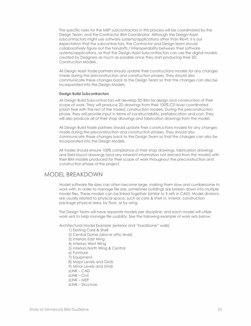
State of Minnesota BIM Guideline 25
The specific roles for the MEP subcontractors in this process will be coordinated by the
Design Team, and the Contractor BIM Coordinator. Although the Design-Assist
subcontractors might use software systems/applications other than Revit, it is our
expectation that the subcontractors, the Contractor and Design team should
collaboratively figure out the handoffs / interoperability between their software
systems/applications, so that the Design-Assist Subcontractors can use the digital models
created by Designers as much as possible once they start producing their 3D
Construction Models.
All Design Assist trade partners should update their constructions models for any changes
made during the preconstruction and construction phases. They should also
communicate these changes back to the Design Team so that the changes can also be
incorporated into the Design Models.
Design Build Subcontractors
All Design Build Subcontractors will develop 3D BIM for design and construction of their
scope of work. They will produce 2D drawings from their 100% CD level coordinated
(clash free with the rest of the trades) construction models. During the preconstruction
phase, they will provide input in terms of constructability, prefabrication and cost. They
will also produce all of their shop drawings and fabrication drawings from the model.
All Design Build trade partners should update their constructions models for any changes
made during the preconstruction and construction phases. They should also
communicate these changes back to the Design Team so that the changes can also be
incorporated into the Design Models.
All trades should ensure 100% compliance of their shop drawings, fabrication drawings
and field layout drawings (and any inherent information not derived from the model) with
their BIM models produced for their scope of work throughout the preconstruction and
construction phase of the project.
MODEL BREAKDOWN
Model software file sizes can often become large, making them slow and cumbersome to
work with. In order to manage file size, sometimes buildings are broken down into multiple
model files. These models can be linked together (similar to X-refs in CAD). Model divisions
are usually related to physical space, such as core & shell vs. interior, construction
package physical area, by floor, or by wing.
The Design Team will have separate models per discipline, and each model will utilize
work sets to help manage file usability. See the following example of work sets below:
Architectural Model Example (exterior and “backbone” walls)
1) Existing Core & Shell
2) Central Dome (above attic level)
3) Interiors East Wing
4) Interiors West Wing
5) Interiors North Wing & Central
6) Furniture
7) Equipment
8) Major Levels and Grids
9) Minor Levels and Grids
zLINK – CAD
zLINK – Civil
zLINK – MEP
zLINK – Structure

State of Minnesota BIM Guideline 26
COLLABORATION PLAN
This section describes how all team members will collaborate on this project to reduce
latency in decision making and ensure efficient execution of all BIM processes.
Coordination Meetings
Reoccurring Coordination Meetings should be held a minimum of once a month. These
meetings will begin during the modeling of the current conditions. The BIM Manager will
initially schedule the BIM Coordination meetings. The Design Team, the Contractor, and
Owner will be required to attend these meetings. These meetings will help develop the
BIM Implementation plan and resolve model coordination issues.
Once construction begins, the Contractor should schedule the BIM Coordination
meetings. The detailer for each trade shall attend, and a project manager’s attendance
is recommended.
Model Folders Structure:
Models Example:
Design Models
Architectural
Mechanical
Structural
Subcontractor Models
(Company Name) Ductwork
(Company Name) Electrical
(Company Name) Fire
(Company Name) Piping
(Company Name) Plumbing
Model Nomenclature
Design Models – “Discipline-System/Component-Level/Area”
Examples: Arch-Base-01A
Arch-Ceilings-01A
Struct-Base-01A
Mech-Duct-01A
Mech-Pipe-01A
Trade Models – “Company Acronym-Component-Level/Area”
Examples: XXX-Duct-01A
XXX-Elec-01A
XXX-Pipe-01A
Merged Model Folder Structure
Everyone will have individual folders to create their own models for coordination in
addition to the models used in the weekly meetings.
Merged Models Example:
• Design Coordination Models
• Contractor Coordination Models
• Subcontractor Coordination Models
Merged Model Nomenclature Example:
• 01 – Level 1 Coordination
• 02 – Level 2 Coordination
• 03 – Level 3 Coordination
• 04 – Level 4 Coordination
Design and Subcontractor Merged Model Nomenclature
• File naming nomenclature is at your discretion.

State of Minnesota BIM Guideline 27
MODEL CONTENT + LEVEL OF DEVELOPMENT
The following stipulations will be used for the design model content:
• Level of development can be defined by granularity and object information.
• The level of property information in the modeling objects and assemblies
depends on the intended BIM use for which the model is being used and the
types of analysis that will be performed on the model.
Design models should include all objects with accurate placement, dimensioning (shape
and size) and breakdown as needed to convey design intent and analysis.
Please refer to the State of Minnesota BIM Guideline for additional information on what
will be modeled in the Design Models, Construction Models, and the updates that will be
made to the Record model.
The State of Minnesota BIM Guideline also outlines the parameters that are required to be
incorporated into the Design Model for Facilities Management utilization. These
parameters will be incorporated into the Design Models and Record Models.
If any additional special parameters need to be incorporated into the Revit families for
scheduling or reporting, they should be identified in a timely manner so as to allow the
design teams advance notice to build such parameters into the default family templates.
BIM TECHNICAL GUIDELINES
File Templates
All design model Revit files will be started utilizing the Shared Parameters Revit Template.
This will ensure that models coordinate and graphic standards match throughout all
models and drawings.
File Naming Structure:
Agency-Site-Building-_ _[discipline designator]-Description.ext
Discipline Designator (may include but not limited to):
Architecture A
Civil / Site Work C
Plumbing P
Electrical E
Mechanical M
Fire Protection FP
Structural S
Tele/Data T
Security SY
.ext = File Type Extension (may include but not limited to):
AutoCAD Web Format File dwf
AutoCAD Drawing File: dwg
Industry Foundation Class File: ifc
Tekla File db1
Revit Drawing File rvt
Origin Point
The origin point (0, 0) for all models in their native software applications shall be at the
intersection of gridlines A and B, with a coordinated intersection of the project structure.

State of Minnesota BIM Guideline 28
Units
This Project will utilize the Imperial system of feet and inches for the unit of measure.
Fractions of an inch are displayed in fractions, not decimals.
Software Build Versions
All members of the design teams will be working from the same “Build Version” of their
associated design application software for their discipline.
Layering Guidelines
Any CAD based drawing files that may be used during the design process should follow
the “AIA CAD Layer Guidelines: US National CAD Standards – Version 4”.
Tolerances in BIM
“Model Tolerance” is different from “Field Tolerance” that will vary for different trades
based on their specifications.
This model tolerance is a measure of accuracy of the model objects as they are placed
in the 3D BIM. Even if the objects in the model are placed to an accuracy of 1/256” in the
model but the dimensioned drawings from the model contain dimensions to the level of
accuracy of 1/8” of an inch, 1/8” of an inch will be treated as the “Model Tolerance”.
Model Tolerance will vary based on objects and existing conditions modeled. The model
tolerances shall be discussed and agreed upon by all BIM team members.
Trade Colors
On large projects with multiple trades modeling, it is advantageous to have each trade
model their elements in an assigned color. Color assignments to be determined, if
necessary.
Current Software Guidelines
Revit Architecture – version 2013
Revit Structure – version 2013
Revit MEP – version 2013
AutoCAD Architecture – version 2011
AutoCAD Civil 3D
BIM Workstation Minimum Spec Recommendation
64 bit workstation
4GB RAM
CPU: Intel Core 2 Duo, T9600 @ 2.8 GHz
KEY PROJECT BIM CONTACTS
Each company on the project will identify a key BIM person who will be responsible for the
development and execution of the BIM processes as described in this document to
successfully achieve the BIM Goals stated on the project.
Contact Name Company Email Phone

State of Minnesota BIM Guideline 29
IMPLEMENTATION PLAN TEMPLATE This template shall act as an outline to identify project goals, execution strategies and sequencing, as well as project roles and
responsibilities.
STATE OF MINNESOTA BIM IMPLEMENTATION PLAN TEMPLATE
Project Name & Location:
File Sharing Project Site Location:
Model Origin:
Model Coordinate System:
Project Team:
Discipline/Trade Consultant Contact Person
Insert Name Here Insert Name Here Insert Name Here
Objective / Goal
Milestone
Timeline + Target
Dates Responsible
Deliverables + Performance
Indicators
Strategic Objective/Goal 1:
Description Here
P = Programming
SD = Schematic Design
DD = Design Development
CD = Construction Documentation
Start
End
1.1
P:
SD:
DD:
CD:

State of Minnesota BIM Guideline 30
EQUIPMENT ASSETS Metadata Fields for All Equipment
Parameters/fields and documentation listed in Exhibit C: Equipment Asset Details are to be
collected on all the Equipment Assets listed below. Individual metadata fields listed in Exhibit
C: Equipment Asset Details will be tracked and authored in Revit by the responsible party as
assigned in the Exhibit D: Assets Data Mapping Matrix.
This is not a comprehensive list of Equipment Assets for the State of Minnesota. Each project
shall determine the required assets to track. If some items mentioned below are not being
modeled in the Revit MEP Design &/or Construction models please inform the State of
Minnesota and provide the reason. If there are other pieces of Equipment that the AEC Team
may consider ‘Major HVAC, Electrical or Plumbing Equipment’ or are equipment being
scheduled on the project please inform the State of those items as well.
Equipment Standards are defined and used by all agencies with the State, the Equipment
Standards Code Format is, Category_System_Type_Component
State of Minnesota Equipment
Description Equipment Category Equipment Standard for Revit Model
Fire System FIRPR FIREPR_FIRE_SYSTEM
Fire Pump FIRPR FIREPR_PUMP_FIRE
Eyewash SAFETY SAFETY_EYEWAS
Security Access Control Panel SECURE SECURE_ACCESS_CONTROL_PANEL
Sump Pump PHYPLT PHY_TOOLS_PUMP_SUMP
Drinking Fountain PLUMB PLUMB_FOUNTAIN_DRINKING
Water Heater PLUMB PLUMB_WTR_HTR
Emergency Light ELEC ELEC_LIGHTS_INT_EMERGE
Diesel Emergency Generator ELEC ELEC_SAFETY-GENEM_DIESEL
Electrical Transformer ELEC ELEC_TRNFMR
Breaker Panel ELEC ELEC_PANEL_BRK
Condensing Unit HVAC HVAC_COND_UNIT
Variable Air Volume Unit HVAC HVAC_VAV_UNIT
Air Handler Unit HVAC HVAC_AHU
Air Compressor Unit HVAC HVAC_AIRCOM_UNIT
Chiller HVAC HVAC_CHILL
Expansion Tank HVAC HVAC_EXPAN_TANK
Exhaust Fan HVAC HVAC_FAN_EXHAUS
Return Air Unit HVAC HVAC_FAN_RETURN_UNIT
Chilled Water Pump HVAC HVAC_PUMP_WATER_CHILL
Domestic Water Circulation Pump HVAC HVAC_PUMP_CIRCUL
Humidifier-Steam HVAC HVAC_HUMID_STEAM
Heat Exchanger HVAC HVAC_HEATEX
EXHIBIT C: EQUIPMENT ASSETS
State of Minnesota BIM Guideline 31
EQUIPMENT ASSET DETAILS DESCRIPTION
Below lists the metadata parameters to be collected and tracked for all Assets listed in Exhibit
C: Equipment Assets and should include the fields listed below. Individual fields listed in this
Exhibit document reside in the State of Minnesota Revit Template as Instance Parameters and
will be collected as assigned in Exhibit E: Assets Data Mapping Matrix. These metadata fields
will be mapped from the Record Revit Model into the State’s Real Property Management
System by the State. For Additional details refer to the Share Parameters Revit Template and
Exhibit G: Revit Shared Parameters.
Floor Code
A unique identifier developed by the Owner for each Floor in the IWMS and is associated with
the Level in the Record Revit Model.
Room Code
The unique identifier developed by the Owner and entered into the Revit Architectural Design
Model by the Architect. These codes should be referenced from the linked Architectural
Model coordinating with the Space Names in the Revit MEP model. These Room Codes are
the Primary connection between the Record Revit Model and the IWMS for syncing metadata.
Equipment Use*
A field in the IWMS that has been coordinated to associate with the Mark Field in Revit. The
Mark field is the unique identifying name in Revit for a piece of equipment that also is
associated with Tags on the Plan and Revit Schedules. The State of Minnesota would like a
nomenclature for equipment that is in line with their Equipment Standard. Data is to be
entered in the Revit field when equipment is initially placed in the Revit MEP Design model,
coordinating the Asset Standards with incremental numbering.
Equipment Code
This unique identifier serves as the Primary connector between the Record Revit Model and the
IWMS for syncing Equipment data. The actual Equipment Code is the number listed on the
Barcode Tag that is attached to the corresponding equipment. So that Barcode number is to
be entered into this Revit field for each piece of equipment by the Construction
Manager/Contractor or Sub-Trade.
Equipment Standard
This is an identifying Standard grouping all like pieces of equipment. The State of Minnesota
has an Equipment Standard for each piece of equipment listed along with the Equipment in
Exhibit C-Equipment Assets. The Equipment Standard also has a relationship to the Equipment
Use based on its acronym. The appropriate Equipment Standard is to be entered in the Revit
field when equipment is initially placed in the Revit MEP Design model.
Manufacturer
Field to place the Equipment Manufacturer name and should be entered into this Revit field for
each piece of equipment by the Construction Manager/Contractor or Sub-Trade.
Model Number
Field to place the Equipment Model Number and should be entered into this Revit field for
each piece of equipment by the Construction Manager/Contractor or Sub-Trade.
Serial Number
Field to place the Equipment Serial Number and should be entered into this Revit field for each
piece of equipment by the Construction Manager/Contractor or Sub-Trade.
EXHIBIT D: EQUIPMENT ASSET DETAILS

State of Minnesota BIM Guideline 32
Part Number
Field to place any additional Part Number that might be provided by the Manufacturer and
should be entered into this Revit field for each piece of equipment by the Construction
Manager/Contractor or Sub-Trade.
Classification Code
Field to place the Equipment CSI Uniformat Number and should be entered into this Revit field
for each piece of equipment by the Construction Manager/Contractor or Sub-Trade. This
should follow Uniformat 2010 nomenclature to the Level 5 classification. Level 5 includes the
full Uniformat structure in addition to the CSI MasterFormat Number. For example: Unit Heaters
fall under the Heating Systems and Decentralized Heating Equipment in Uniformat so the Level
5 classification would be D3020.70.238239, whereas 238239 is the MasterFormat Number.
Additional Comments
This is a field at the Instance Level in Revit for Equipment; it is not to be used by the Design
Team, Construction Manager/Contractor or Sub-Trades.
Cost to Replace
Field to place the estimated Cost to Replace the piece of equipment, this field is for
equipment only not labor. Number should be entered into this Revit field for each piece of
equipment by the Construction Manager/Contractor or Sub-Trade.
Install Date
Field to place the date in which the piece of equipment was installed in the building. Date
should be entered into this Revit field for each piece of equipment by the Construction
Manager/Contractor or Sub-Trade.
In Service Date
Field to place the date in which the functional testing/start up occurred and when the
equipment was put into use. Date should be entered into this Revit field for each piece of
equipment by the Construction Manager/Contractor or Sub-Trade.
Equipment Location
Field to place the information about where the equipment is located in a Room or Space. If in
a large open space use the nearest column line intersection and if in a smaller room use a
designation referencing a fixed visible component like a door. Location should be entered
into this Revit field for each piece of equipment by the Construction Manager/Contractor or
Sub-Trade.
Date Warranty Expires
Field to place the date in which the manufacturer’s warranty for the piece of equipment will
expire. Date should be entered into this Revit field for each piece of equipment by the
Construction Manager/Contractor or Sub-Trade.
Life Expectancy
Field to place the estimated Life Expectancy of the piece of equipment. Number, in years,
should be entered into this Revit field for each piece of equipment by the Construction
Manager/Contractor or Sub-Trade.
Subcomponent of Equipment
Field used to track the Parent-Child relationship of equipment. Parent-Child nomenclature
should be entered into this Revit field for each piece of equipment by the Construction
Manager/Contractor or Sub-Trade.
The following documents are required for each piece of equipment shown in Exhibit C-
Equipment Assets. These documents should be coordinated with the Exhibit F: Operations +
Maintenance Support Information.

State of Minnesota BIM Guideline 33
• Product Data • O&M Manuals
• Installation Guide
• Warranty Documents
• Submittal Information
• Commissioning Reports
• Start-Up and Shut Down Procedures • Additional Equipment Testing Documents
EQUIPMENT SCHEMA STANDARDS
Equipment Schema Standards: All equipment entered should follow the following formats.
*Required fields for all equipment.
**Any deviation from this format and the information will not be recognized by the Facilities
Management software.
Revit Field
Name
Database Field
Name
Database
Multi-Line
Heading
Data
Format
Field
Size
# of
Decimals Definition Requirement
Cost To Replace cost_replace Cost To
Replace
numeri
c 12 2
Actual cost to
replace
equipment
based on current
market value.
Includes labor
and materials.
Enter a numeric value no
more than 12 characters
and no use of special
characters or commas.
Classification
Code csi_id
Classification
Code char 16 0
CSI classification
code up to level
5 detail
Enter full CSI classification
code up to level 5 that
best relates to the
equipment. Use Uniformat
2010 nomenclature in
addition to the CSI
MasterFormat #.
(Example:
D3020.70.238239)
In Service Date date_in_service In-Service
Date date 10 0
Date the
equipment was
first used
Enter the date when the
equipment was or is
expected to first be in use
Format: mm/dd/yyyy
Install Date date_installed Install Date date 10 0
Date the
equipment
installation was
completed
Enter the date when the
equipment was or is
expected to be installed.
Format: mm/dd/yyyy
Date Warranty
Expires
date_warranty_
exp
Date
warranty
Expires
date 10 0
Date the
equipment
warranty expires
Enter the date when the
equipment warranty is
expected to expire.
Format: mm/dd/yyyy
Equipment
Code eq_id
Equipment
Code char 24 0
A unique value
for the asset in
the table
Equipment ID must be a
unique value for every
piece of equipment.
Equipment code must be
entered as a numeric
value and be no more
than 8 characters. Enter
codes in sequential order.

State of Minnesota BIM Guideline 34
Revit Field
Name
Database Field
Name
Database
Multi-Line
Heading
Data
Format
Field
Size
Number
of
Decimals
Definition Requirement
Life Expectancy eq_life_expct Life
expectancy date 10 0
End date of the
equipment life
expectancy
Enter the date when the
equipment life
expectancy is expected
to expire.
Format: mm/dd/yyyy
Equipment
Location eq_location
Equipment
Location char 100 0
Short description
of the
equipment
location
Enter a 100 character or
less description of where
the equipment is located
in the building
Equipment
Standard eq_std
Equipment
standard char 50 0
Equipment
standards allows
equipment
categories to be
assigned to the
equipment
Select the Equipment
Standard that best fits
from the eqstd table.
Refer to sheet eqstd.
Manufacturer eqmfr_id Equipment
manufacturer char 16 0
The
manufacturer
that
manufactured or
produced the
equipment.
Select the Equipment
Manufacturer that best
fits from the eqmfr table.
Refer to sheet eqmfr.
Manufacturer
Part Number eqmfr_partnum
Equipment
manufacturer
part number
char 32 0
Manually
entered unique
part number as
specified by the
equipment
manufacturer
Enter the manufacturer's
part number not to
exceed 32 characters
Model Number eqmodel Model
number char 100
Manually
entered unique
model number
identifying the
piece of
equipment
Enter the equipment
model number not to
exceed 100 characters
Serial Number num_serial Serial number char 32 0
Manually
entered unique
serial number
identifying the
piece of
equipment
Enter the equipment's
serial number. use no
more than 32 characters
Subcomponent
Of
subcomponent
_of
Sub-
component
of equipment
char 24 0
Manually
entered field
identifying the
specific
equipment of
which this piece
is a subassembly
Enter the eq_id of main
piece of equipment this is
a subassembly of. Must
be no more than 8
characters
Mark use1 Equipment
Use char 50 0
Required field
used to describe
the purpose of
the piece of
equipment
within the
building
Enter a unique descriptive
name for the equipment.
Equipment use must not
be more than 50
characters

State of Minnesota BIM Guideline 35
ASSETS DATA MAPPING MATRIX
This document lays out the roles and responsibilities for capturing data. Below is an example template.
Information Category Equipment Asset Details Data Entry
Party
Data Authoring
Software Revit Shared Parameters Field
Building Program Data Site Code Owner ARCHIBUS N/A
Building Program Data Building Code Owner ARCHIBUS N/A
Spatial Location Data Floor Code Owner ARCHIBUS Level†
Spatial Location Data Room Code Design Team Both Room Number†
Asset Data Properties Equipment Use (Tag on Drawings) Design Team Revit Mark†
Asset Data Properties Equipment Code (Asset Tag) Contractor Revit Equipment Code*
Asset Data Properties Equipment Standard Design Team Revit Equipment Standard*
Manufacture Information Manufacturer Contractor Revit Manufacturerᶻ
Manufacture Information Part Number Contractor Revit Manufacturer Part Numberᶻ
Manufacture Information Model Number Contractor Revit Model Numberᶻ
Manufacture Information Serial Number Contractor Revit Serial Numberᶻ
Manufacture Information Classification Code (CSI Uniformat Number) Contractor Revit Classification Codeᶻ
Manufacture Information Additional Comments Owner ARCHIBUS Comments†
Cost Requirements Cost to Replace Contractor Revit Cost to Replaceᶻ
Facility Management In Service Date Contractor Revit In Service Dateᶻ
Facility Management Install Date Contractor Revit Install Dateᶻ
Facility Management Equipment Location Contractor Revit Equipment Locationᶻ
Facility Management Date Warranty Expires Contractor Revit Date Warranty Expiresᶻ
Facility Management Life Expectancy Contractor Revit Life Expectancyᶻ
Facility Management Subcomponent of Equipment Contractor Revit Subcomponent Ofᶻ
†Existing Revit Field *Parameter Created by ARCHIBUS ᶻShared Parameter
EXHIBIT E: ASSETS DATA MAPPING MATRIX

State of Minnesota BIM Guideline 36
OPERATIONS + MAINTENANCE SUPPORT INFORMATION (OMSI)
OMSI should coordinated with the Equipment Attachments and be provided as PDF files.
Required Information Description
Introduction Facilities Description with outline and structure of O&M content
System Level Description Description of the system and its purpose, how it operates, and any
interfaces it may have
Preventive Maintenance
System-level tables guide maintenance personnel, via fault tree analysis, in
a sequential, step-by-step isolation of a system problem to identify faulty
equipment. Typical malfunctions, tests or inspections, and corrective
actions or recommendations to correct malfunctions are included
Plumbing Related to domestic water and sanitary waste systems
Fire Protection Related to wet/dry pipe sprinkler systems
HVAC Related to systems, including automated controls and exhaust, space
heating, and central air systems
Fire Detection & Intrusion
Alarms Related to detection and alarm systems (wet/dry pipe sprinkler)
Electrical Related to power distribution equipment and backup/emergency
electrical (uninterruptible power supply, generator)
Conveying General information and preventive maintenance for elevators,
escalators, wheel chair lifts, conveyors, etc.
Operating Procedures Controls/Startup/Shutdown/Emergency Over-Ride/Seasonal Changeover:
Include equipment configurations for each mode of operation
Manufactures' Literature
Identifies manuals, cut sheets, etc., from equipment manufacturers that
amplify information provided within the system-level O&M manual.
Manufacturers’ literature generally provides procedures to operate,
maintain, troubleshoot, and repair specific items at the equipment level.
This information is contained in a separate volume of binders, identified by
facility/system, for easy reference. Specific material or complete
documents can also be electronically scanned for its ‘on-line’ use, such as
linking from the system-level manual
Warranties & Bonds For Systems, Equipment or Component Parts of Equipment put into service
during construction.
EXHIBIT E: OPERATIONS + MAINTENANCE SUPPORT INFORMATION

State of Minnesota BIM Guideline 37
REVIT SHARED PARAMETERS
Overview
This is an electronic file named State of Minnesota ARCHIBUS Shared Parameters File Template.
Use this Revit .rte file to transfer Project Standards from the Template File to the Revit MEP
Design Model, Revit MEP Construction Model and the Record Revit MEP Model.
This will create the Instance Parameter fields for metadata requested by the State of
Minnesota for MEP Equipment in the project models based on the Exhibit B: Equipment Asset
Details. Author the requested information into these fields.
Process
1. Open the State of Minnesota ARCHIBUS Shared Parameters File Template while also having
one of the MEP files listed above open.
2. Using the model file as the active and open window, go the ‘Mange’ tab and select
‘Transfer Project Standards’.
3. The following ‘Select Items to Copy’ window will pop up. In the ‘Copy from:’ drop down
select the State of Minnesota ARCHIBUS Shared Parameters File Template.
4. Then select the ‘Check None’ button to deselect all the checked items in the window.
5. Find the ‘Project Parameters’ field and re-select it.
6. Then click the ‘OK’ button.
7. At the Instance Level in Revit you will now find these Shared Parameters for MEP Equipment
on the project so that metadata required by the State of Minnesota can be authored into
these fields.
Transfer of Shared
Parameters from the
Template file to the
active model
EXHIBIT F: REVIT SHARED PARAMETERS

State of Minnesota BIM Guideline 38
REFERENCES
This is an overview of supplementary information, resources and references used in the State of
Minnesota BIM Guideline.
The American Institute of Architects. Guide, Instructions and Commentary to the 2013 AIA
Digital Practice Documents: AIA Document E203™–2013, Building Information Modeling and
Digital Data Exhibit AIA Document G201™–2013, Project Digital Data Protocol Form AIA
Document G202™–2013, Project Building Information Modeling Protocol Form. 2013
http://www.aia.org/groups/aia/documents/pdf/aiab095711.pdf
BIMForum. 2013 Level of Development Specification. AIA / AGC, August 22, 2013.
http://bimforum.org/wp-content/uploads/2013/08/2013-LOD-Specification.pdf
CIC Research Group, Department of Architectural Engineering, and The Pennsylvania State
University. BIM Project Execution Planning Guide. Creative Commons License. 2011.
United States General Services Administration. GSA Building Information Modeling Guide Series:
03 - GSA BIM Guide of 3D Imaging. 2012. http://www.gsa.gov/bim
NYC Department of Design and Construction. DDC BIM Guidelines. July 2012.
http://www.nyc.gov/html/ddc/downloads/pdf/DDC_BIM_Guidelines.pdf
RESOURCES
Questions regarding the State of Minnesota BIM Guideline should be directed to:
Fred Anderson
Enterprise CAFM Systems Coordinator
State of Minnesota
AUTHORS
Laura Blanks
Principal Planner, OSD - MR
Department of Natural Resources
State of Minnesota
Zach Eling
CAFM Administrator
Minnesota Zoological Garden
State of Minnesota
Keelan Hanks
TIFM Administrator
Department of Administration
State of Minnesota
EXHIBIT G: REFERENCES + RESOURCES