state of kuwait - kuwait international airport · 2.1 visibility and traffic conditions 2.1.1 the...
TRANSCRIPT

STATE OF KUWAIT
AVIATION SAFETY DEPARTMENT
Guidance Material
Surface of Movement Guidance and Control System
SMGCS
Issue-1, Rev 0
April 2017

ACS/1429 Issue 1, Revision 0
Page 2 of 88 April 2017
List of Amendments
S/No. Issue
No.
Rev.
No.
Amended by Signature Date
1) 1 0 Engr. Shaheen M Al-Ghanim
Aviation Safety Director April 2017

ACS/1429 Issue 1, Revision 0
Page 3 of 88 April 2017
LIST OF EFFECTIVE PAGES
Number Effective Date Entered Date Entered by

ACS/1429 Issue 1, Revision 0
Page 4 of 88 April 2017
Forward
The Aviation Safety Department guidance material is published to keep pace with the
guidelines prescribed by ICAO documents and publications. The objective of this
guidance material is to assist Kuwait International Airport’s staff towards safety and
fulfil the obligations to comply with the published KCASRs.

ACS/1429 Issue 1, Revision 0
Page 5 of 88 April 2017
Table of Contents Forword ............................................................................................. Error! Bookmark not defined.
Chapter 1 .......................................................................................................................................... 8
Introduction ...................................................................................................................................... 8
1.1 Why SMGCS .................................................................................................................... 8
1.1 Operational Requirements of Surface Movement Guidance and Control Systems .......... 8
1.1.1 Requirements of a general nature ............................................................................. 8
1.1.2 Requirements of pilots .............................................................................................. 9
1.1.3 Requirements of appropriate control units ............................................................... 9
1.1.4 Requirements of ground vehicles on the movement area ......................................... 9
Chapter 2 .......................................................................................................................................... 9
Designing an SMGC System for an Aerodrome .............................................................................. 9
2.1 Visibility and traffic conditions ......................................................................................10
2.2 Basic Equipment Requirements .....................................................................................10
2.3 Basic Procedural/ Administration Requirements ...........................................................11
2.4 Matching Aids to Aerodrome Conditions ......................................................................12
2.5 Review of System and Improvement .............................................................................12
Chapter 3 ........................................................................................................................................13
Functions and Responsibilities .......................................................................................................13
3.1 Division of responsibilities and their transfer.................................................................13
3.2 Avoidance of overcontrol ...............................................................................................14
3.3 Ground Movement Communications .............................................................................15
3.4 Establishment of Standard Taxi Routes for Aircraft ......................................................15
3.5 Control of Ground Vehicles ...........................................................................................16
3.6 Monitoring ......................................................................................................................17
3.7 Aerodrome Surface Inspections .....................................................................................17
3.8 Maintenance ...................................................................................................................18
3.9 Special fault rectification ................................................................................................18
3.10 Training ..........................................................................................................................18
Chapter 4 ........................................................................................................................................19
Procedures ......................................................................................................................................19

ACS/1429 Issue 1, Revision 0
Page 6 of 88 April 2017
4.1 Introduction ....................................................................................................................19
4.2 Traffic flow.....................................................................................................................19
4.3 Effects of Visibility on SMGC Procedures ....................................................................20
4.4 Modes of Operation ........................................................................................................21
4.5 Separation at Intersections and Longitudinal Spacing ...................................................22
4.6 The Role of Surface Movement Radar (SMR) ...............................................................24
4.7 Emergency Procedures ...................................................................................................25
4.8 RTF Procedures and Phraseology ..................................................................................26
4.9 Co-Ordination .................................................................................................................27
Chapter 5 ........................................................................................................................................28
Low Visibility Operations ..............................................................................................................28
5.1 Introduction ....................................................................................................................28
5.2 Preparation for Low Visibility Operations .....................................................................28
5.3 Low visibility procedures ...............................................................................................29
5.4 Emergency Procedures ...................................................................................................31
5.5 Summary ........................................................................................................................32
Chapter 6 ........................................................................................................................................34
High Traffic Volume Operations ...................................................................................................34
6.1 General ...........................................................................................................................34
6.2 Planning and Simulation ................................................................................................34
6.3 Runway Protection .........................................................................................................35
6.4 Standard taxi-routes and charts ......................................................................................35
6.5 Ground Control Organization and RTF Frequencies .....................................................36
6.6 Aircraft stand allocation and holding .............................................................................36
6.7 Special equipment ..........................................................................................................36
Chapter 7 ........................................................................................................................................36
Runway Protection Measures .........................................................................................................36
7.1 Introduction ....................................................................................................................36
7.2 The Operational Problem ...............................................................................................37
7.3 Protection Measures .......................................................................................................37
7.4 Runway Protection Methods and Equipment .................................................................38

ACS/1429 Issue 1, Revision 0
Page 7 of 88 April 2017
7.5 Summary ........................................................................................................................40
Chapter 8 ....................................................................................................................................41
Apron Management Service .......................................................................................................41
8.1 General ...........................................................................................................................41
8.2 Who operates the apron management service?...............................................................42
8.3 Responsibilities and Functions .......................................................................................43
8.4 Special procedures for low visibility conditions ............................................................45
8.5 Training ..........................................................................................................................45
Appendix A ....................................................................................................................................47
Further Information on Visual Aids* .............................................................................................47
Appendix B ....................................................................................................................................49
Examples of Low Visibility Procedures .........................................................................................49
Appendix C ....................................................................................................................................73
Examples of Apron Management Services ....................................................................................73
Appendix D ....................................................................................................................................80
Taxiway Computer Model London Heathrow Airport ...................................................................80
Appendix E .....................................................................................................................................82
Traffic Rules and Regulations for Surf ace Vehicles .....................................................................82
Appendix F .....................................................................................................................................84
Performance Objectives for Surface Movement Radar (SMR) ......................................................84
ACS/1429 Issue 1, Revision 0
Page 8 of 88 April 2017
Chapter 1
Introduction
1.1 Why SMGCS
1. SMGC system is aiming to enable an aerodrome to operate safely in the intended conditions.
The system should be designed to prevent collisions between aircraft, between aircraft and
ground vehicles, between aircraft and obstacles, between vehicles and obstacles, and between
vehicles. In the simplest case.
2. Safeguard against unauthorized or inadvertent entry onto operational runways.
3. Provide assistance to rescue and fire fighting vehicles in locating and proceeding to the site of
an accident on the movement area
4. Maintain regularity of movement under varying operational conditions.
- A surface movement guidance and control (SMGC) system consists of the provision of
guidance to, and control or regulation of, all aircraft, ground vehicles and personnel on the
movement area of an aerodrome.
- Applied to the system of aids, facilities, procedures and regulations designed to meet the
particular requirements for guidance to, and control or regulation of, surface traffic consistent
with the particular operational needs at an aerodrome
- SMGC system involve with the appropriate branches of the administration of the State
concerned, including aerodrome engineering, the air traffic control unit, communications and
operations specialists, operators, pilots and, where appropriate, the military.
1.1 Operational Requirements of Surface Movement Guidance and Control Systems
The system should be appropriate to the visibility and traffic density and should provide:
1.1.1 Requirements of a general nature
a) communication capability between the appropriate control unit(s), between the appropriate
control unit(s) and aircraft and between the appropriate control unit(s) and ground vehicles;
b) acceptable work-loads on the users of the SMGC system;
c) optimum use of aids and procedures already specified in DGCA KCASRs regulatory
documents;
d) compatibility between individual elements of the guidance and control systems; and
e) Current and forecast meteorological conditions.
ACS/1429 Issue 1, Revision 0
Page 9 of 88 April 2017
1.1.2 Requirements of pilots
a) orientation, guidance and control beginning at the end of landing roll-out on arrival, to the
parking position, and from the parking position up to alignment for take-off on departure;
b) information on the route to be followed;
c) information on position along the route being followed;
d) guidance along the route being followed and parking guidance;
e) warning of:
1) changes in direction;
2) stops and other speed adjustments;
f) identification of areas to be avoided;
g) information to prevent collision with other aircraft, ground vehicles or obstacles; and
h) Information on system failures affecting safety.
1.1.3 Requirements of appropriate control units
a) information on the identity, position and progress of aircraft including aircraft under tow;
b) information on the identity, position and progress of ground vehicles whose movements might
conflict with aircraft movements;
c) information on the presence of temporary obstacles or other hazards;
d) information on the operational status of elements of the system; and
e) facilities appropriate to the control to be exercised.
1.1.4 Requirements of ground vehicles on the movement area
a) emergency vehicles
1) information on the route to be followed;
2) guidance along the route being followed;
3) capability to locate the site of an emergency;
4) information to prevent collision with aircraft and ground vehicles; and
b) other ground vehicles
1) information on the route to be followed;
2) guidance along the route being followed;
3) Information to prevent collision with aircraft and ground vehicles.
Chapter 2
Designing an SMGC System for an Aerodrome

ACS/1429 Issue 1, Revision 0
Page 10 of 88 April 2017
2.1 Visibility and traffic conditions
2.1.1 The visibility conditions under which the aerodrome authority plans to maintain operations and
the traffic density are the two most important factors to be considered when selecting
components for a surface movement guidance and control (SMGC) system for an airport. See
Table 2-1
Table 2-1. Visibility and traffic conditions associated with SMGC systems - Explanation of terms
VISIBILITY CONDITIONS
1 Visibility sufficient for the pilot to taxi and to avoid collision with other traffic
on taxiways and at intersections by visual reference, and for personnel of
control units to exercise control over all traffic on the basis of visual
surveillance;
2 Visibility sufficient for the pilot to taxi and to avoid collision with other traffic
on taxiways and at intersections by visual reference, but insufficient for
personnel of control units to exercise control over all traffic on the basis of
visual surveillance; and
3 Visibility less than 400 m RVR (low visibility operations).
TRAFFIC DENSITY
(in the mean busy hour as determined by the individual State)
Light Not greater than 15 movements per runway or typically less than 20 total
aerodrome movements;
Medium Of the order of 16 to 25 movements per runway or typically between 20 to 35
total aerodrome movements; and
Heavy Of the order of 26 or more movements per runway or typically more than 35
total aerodrome movements.
2.2 Basic Equipment Requirements
Markings:
- runway center line
- taxiway center line
- taxi-holding position
- taxiway intersection
- apron
- restricted use areas
ACS/1429 Issue 1, Revision 0
Page 11 of 88 April 2017
Lighting:
- runway edge
- taxiway edge
- obstacle lights
- restricted use areas
Signs:
- mandatory signs, e.g. taxi-holding position, NO ENTRY, STOP
- information signs, e.g. location and destination
Other:
- aerodrome chart
- aerodrome control service
- signaling lamp
- Radiotelephony equipment.
2.2.1 The equipment required at a particular aerodrome for provision of an SMGC system will
depend both on the density of traffic and the visibility conditions in which the operations should
take place see appendix A
2.3 Basic Procedural/ Administration Requirements
Aerodrome authority
- designation of taxiways
- movement area inspections
- regulation of ground staff conduct on the movement area
- regulation of ground staff radiotelephony procedures
- periodic electrical monitoring of SMGC aids
- initiation of amendment of aerodrome chart as necessary
- apron management
Air traffic services
- provision of air traffic control services
- use of radiotelephony procedures and phraseology
- use of signaling lamp
- monitoring of SMGC aids
Pilot
- adherence to ground movement traffic rules and regulations
- Use of radiotelephony procedures and phraseology.
Visual docking

ACS/1429 Issue 1, Revision 0
Page 12 of 88 April 2017
In evaluating the need for a visual docking guidance system the following factors merit
consideration:
- the number of aircraft using the aircraft stand
- weather conditions
- space available on the apron
- precision required at the parking position
- Availability and cost of alternative means.
Signs
- As traffic increases or visibility decreases improvements in the signs provided as well as the
lighting and electronic aids used for guidance and control are required.
Charts
- The aerodrome authority should assess the number of charts required in accordance with the
amount of information required to be shown.
2.4 Matching Aids to Aerodrome Conditions
the number of aircraft using the aircraft stand
weather conditions
space available on the apron
precision required at the parking position
Availability and cost of alternative means.
2.5 Review of System and Improvement
2.5.1 Regular reviews of the SMGC system should be carried out to ensure that the system is fulfilling
its intended task.
2.5.2 In all cases, the SMGC system will need to be reviewed under one or more of the following
circumstances:
a) the volume of traffic increases significantly;
b) operations in lower visibility conditions are planned; and
c) The aerodrome layout is changed, i.e. new runways, taxiways, or aprons are brought into
operation.
2.5.3 Apart from traffic movement counts, the extent to which increased traffic volume is causing a
deterioration of the effectiveness of the SMGC system may be determined by the appearance
of the following symptoms:

ACS/1429 Issue 1, Revision 0
Page 13 of 88 April 2017
a) a marked need for increased vigilance in the visual surveillance of surface traffic movements,
generated by the number of movements occurring simultaneously throughout the aerodrome
complex;
b) a marked increase in the loading on the communications channels used for SMGC;
c) an increase in the number of problems occurring at crossing points and runway/taxiway
intersections, requiring intervention by the controller and thereby contributing to the increase
in radio communications; and
d) The occurrence of bottlenecks, congestion and delay: in surface traffic movements.
Chapter 3
Functions and Responsibilities
3.1 Division of responsibilities and their transfer
Air traffic services
3.1.1 Use of radiotelephony procedures and phraseology.
3.1.2 When aircraft and vehicles operate outside the maneuvering area but under the guidance of an
ATS unit it is preferable that detailed written procedures governing their operation be
employed.
3.1.3 Issue of taxi clearance to facilitate SMGC.
3.1.4 Determination of taxi routes to be followed.
3.1.5 Monitoring of SMGC system aids.
3.1.6 Control of traffic other than aircraft on the maneuvering area
3.1.7 Operation of visual guidance and control aids.
3.1.8 Division of responsibility between controller and pilot.
3.1.9 Initiation and termination of low visibility procedures.
Apron management service
3.1.10 At some aerodromes, management of traffic on the apron is not the responsibility of the air
traffic control unit. At these aerodromes there should be an apron management service
responsible for ensuring the safe movement of aircraft on the apron.

ACS/1429 Issue 1, Revision 0
Page 14 of 88 April 2017
Pilots
3.1.11 The pilot will respond to the instructions given by the apron management service and the air
traffic control unit and follow the designated taxiway route.
Aerodrome authority
3.1.12 Movement area inspections
3.1.13 Ensuring that ground staff are properly trained particularly in RTF and monitored in its use.
3.1.14 Servicing of SMGC aids
3.1.15 Designation of taxiways and standard taxi routes.
3.1.16 Low visibility movement area protection measures.
Ground vehicle drivers
3.1.17 Must comply with aerodrome regulations and ATC instructions. Notwithstanding this, drivers
are responsible for exercising due care and attention so as to avoid collisions between their
vehicles and aircraft, and between their vehicles and other vehicles.
3.2 Avoidance of overcontrol
3.2.1 SMGC system should provide a degree of control which is adequate to meet the needs of pilots
and controllers.
3.2.2 It is important to ensure that the efficiency of the over-all system is not impaired by the
imposition of unnecessary controls and restrictions on pilots and controllers.
3.2.3 With contemporary SMGC systems the traffic capacity may be reduced by the need.
3.2.4 Major considerations of ground movement control in low visibility operations should be to:
a) avoid traffic conflicts between taxiing aircraft and between an aircraft and a ground vehicle;
b) ensure that aircraft or ground vehicles do not enter the ILS critical or sensitive areas at an
improper time;
c) ensure that the runway in use is clear when an aircraft is landing or taking off;
d) facilitate taxiing to and from the runway; and
e) Maintain the maximum safe capacity of the airport.
3.2.5 All aircraft and other vehicles operated on the maneuvering area of a controlled aerodrome
must be subject to aerodrome control, and controlled by radio communications.
3.2.6 Control of ground movement of aircraft and vehicles during periods of low visibility should be
based on maximum use of procedures and aids
ACS/1429 Issue 1, Revision 0
Page 15 of 88 April 2017
3.2.7 Aids must be provided to substitute for the visual information normally available to pilots and
controllers for surveillance and guidance information.
3.2.8 Although visual aids and procedures may be adequate for ground movement in low visibility,
such operations must be conducted with extra caution. As traffic demand increases.
3.3 Ground Movement Communications
3.3.1 The communication aspects of an aerodrome control service fall into three main categories:
a) control of air traffic in the circuit and in the approach, landing and departure phases of flight
b) control of taxiing aircraft and vehicles on the maneuvering area; and
c) Acquisition and passing of airways clearances, weather information and other flight data.
3.3.2 In a developing aerodrome or traffic situation the point at which additional control positions
need to be introduced may hinge solely upon RTF channel loading
3.3.3 In some instances it may become necessary to open an additional frequency or frequencies,
during the busy hours of the day and then revert to a more limited communication channel
usage in the less busy periods
3.3.4 Non-aeronautical radio frequencies to be used for communication between ground vehicles and
various aerodrome agencies which does not preclude maintenance of a listening watch on the
ground movement control frequency.
3.3.5 A spare frequency for use if a normal channel is jammed/overloaded is a highly desirable
facility
3.3.6 For a discrete RTF contact between emergency services vehicles and an aircraft which has
landed after declaring an emergency, or in any emergency when the aircraft is on the ground
and capable of being maneuvered. For such a discrete frequency to be of value it is obviously
necessary that the users of radiotelephony equipment in these circumstances be able to
communicate in a common language. For situations where a common language does not exist,
communication between the pilot and the fire service will have to be relayed by ATC.
3.4 Establishment of Standard Taxi Routes for Aircraft
3.4.1 On an aerodrome the movement of taxiing aircraft generally falls into a distinctive pattern in
which the major traffic flows are between:
a) runways and aprons
b) aprons and maintenance areas
c) Maintenance areas and runways.
3.4.2 Care should be taken to ensure that the routes are adequate for the largest aircraft likely to use
them, and that aircraft using them do not offer problems of:
ACS/1429 Issue 1, Revision 0
Page 16 of 88 April 2017
a) interference with navigation aids;
b) penetration of the obstacle free zone and, where possible, penetration of other obstacle
limitation surfaces;
c) obstruction of radar transmissions;
d) physical obstruction (e.g. inadequate clearance from aircraft holding for take-off from an
intermediate point); or
e) Jet blast.
3.4.3 Routes will vary according to the runways in use for landing and take-off.
3.4.4 For aerodromes where standard taxi routes are provided, details of such routes should be
published in the appropriate aeronautical information publication and shown on aerodrome
charts.
3.4.5 An established standard taxi route system offers advantages over a random system
3.5 Control of Ground Vehicles
3.5.1 KCASR 11 and KCASR-14 require that the movement of persons and vehicles on the
movement area shall be controlled or regulated as necessary to avoid hazards to them or to
aircraft Part 2, Chapter 4 stresses the importance of planning aerodrome facilities for the
maximum segregation of aircraft and vehicular traffic
3.5.2 The Aerodrome Design Manual, Part 2, also points out the value of airside roads to eliminate,
or lessen, the use of runways and taxiways by ground vehicles which need access to the
movement area.
3.5.3 Apron safety lines should be provided on a paved apron to define the limits of areas established
for use by ground vehicles and other aircraft servicing equipment.
3.5.4 Airside route systems for vehicle movement fall into five broad categories:
a) roads which are completely segregated from aircraft movements;
b) roads which cross taxiways in maintenance areas but which are segregated from operational
aircraft movement;
c) routes which cross operational runways, stopways, clearways or taxiways;
d) apron routes; and
e) Vehicle movement along operational taxiways and runways.
3.5.5 Where construction or other activity calls for localized free moving traffic, the boundaries of a
temporarily closed area should be marked as described in KCASR-14, and any movement
outside the area should comply with normal aerodrome regulations.
3.5.6 Detailed written procedures particularly for apron activities based on methods other than RTF,
should be developed for low visibility operations by the appropriate authority to ensure safety
while maintaining capacity.
ACS/1429 Issue 1, Revision 0
Page 17 of 88 April 2017
3.6 Monitoring
3.6.1 Lighting aids
3.6.1.1 Surface movement guidance and control relies heavily upon lights for safe operations in
reduced visibility and at night
3.6.1.2 Ideally all lights should be operative but as a guide for maintenance it is considered that not
more than 20 per cent of taxiway center line lights should be inoperative, and two consecutive
taxiway center line lights should not be inoperative.
3.6.1.3 In conditions when direct visual appraisal of aerodrome surface lights is not possible,
monitoring is usually carried out by:
a) observation of "mimic" or "tell-tale" lights on the lighting control panel; and
b) Checking of power supply and circuit state indicators.
3.6.1.4 Information is available in the Aerodrome Design Manual, Part 5, Electrical Systems,
concerning the type of electrical monitoring system which should be installed Sample monitor
signals to indicate the operational status of an installation are:
a) installation out of order: tell-tale light off;
b) installation in order: tell-tale light on and steady; and
c) Installation faulty when switched on: tell-tale light blinking.
3.6.1.5 The extent and detail of monitoring that can be done in the control tower will depend upon the
size and complexity of the lighting system
3.6.1.6 To ensure the integrity of monitoring systems it is desirable that their power supply should be
obtained from a separate source.
3.6.2.1 With the introduction of non-visual aids to SMGC the dependence of ATC upon the correct
functioning of the non-visual aids will be such that, as with aerodrome lighting, a monitor
system must be provided to indicate any malfunction.
3.7 Aerodrome Surface Inspections
3.7.1 Frequency of Inspection
3.7.1.1 Inspections of the movement area should be regular and frequent. Guidance on inspections is
provided in the Airport Services Manual (Doc 9137), Part 8. It recommends that the minimum
frequency should be:
a) Runways - Four inspections daily (Dawn inspection, Morning inspection, Afternoon inspection
and Dusk inspection).
b) Taxiways
c) Aprons

ACS/1429 Issue 1, Revision 0
Page 18 of 88 April 2017
d) Grass areas
3.8 Maintenance
3.8.1 Guidance on the preventive maintenance of lighting system is contained in KCASR 14, Chapter
9, and in the Airport Services Manual, Part 9. Plus the various visual aids of the SMGC system
comprising route guidance are listed in table 2-2.
3.8.2 The integrity and reliability of the SMGC system should match the other visual and non-visual
navigation aids.
3.8.3 Special checks. Where visual aids are provided for operations in low visibility
3.8.4 Where high intensity taxiway center line and stop bar lighting is provided for low visibility
operations, particular attention should be paid to cleanliness of taxiway center line and stop bar
lights, and to the conspicuity of taxiway center line and apron markings.
3.8.5 Special inspections should be carried out before a section of a taxiway is returned to operational
use if it had been closed for maintenance, snow clearance or other reasons.
3.8.6 Routine maintenance. The extent to which routine maintenance can be combined with routine
inspection will depend upon local arrangements.
3.8.7 Daily maintenance at busy aerodromes with high sustained movement rates is difficult to
arrange. and work within the movement area may have to be carried out at night
3.9 Special fault rectification
3.9.1 In addition to the routine maintenance, it will be necessary at busy and complex aerodromes to
have personnel available for special fault rectification when failures occur which affect the
ability of the system to meet the operational requirement.
3.9.2 special fault rectification will be necessary where consecutive lamp failures have occurred
within the taxiway center line lights or stop bars
3.9.3 When a fault occurs during low visibility operations, it will be necessary to consider whether
the system can continue to give safe guidance and control without immediate fault rectification
or whether operations have to be restricted while the fault is being rectified.
3.10 Training
3.10.1 The training requirements of licensed personnel authorized to operate on the movement area or
involved in the provision of the SMGC system, is the responsibility of the appropriate authority,
Training falls into two main categories: initial and recurrent or proficiency training.
ACS/1429 Issue 1, Revision 0
Page 19 of 88 April 2017
3.10.2 Initial training is provided by the appropriate authority to all new employees and newcomers to
a specific unit. It normally covers but is not limited - to:
- RTF procedures
- aerodrome layout
- aerodrome procedures
- aerodrome emergency procedures
- aerodrome low visibility procedures
- aerodrome special procedures
- aircraft recognition
- Vehicle operating procedures.
3.10.3 Recurrent or proficiency training should not be overlooked. When dealing with low visibility
operations, this training may be critical since the exposure to low visibility procedures is limited
due to one or both of the following:
a) the infrequent occurrence and short duration of low visibility conditions; and
b) Individual shift rotation or extended absence from duty for whatever reason.
3.10.4 It is suggested that appropriate recurrent training be given at least every six months.
Chapter 4
Procedures
4.1 Introduction
4.1.1 The basis for all operations on the maneuvering area of an aerodrome is contained in KCASR-
14. These documents prescribe rules and requirements for the operation of aircraft and vehicles
on the maneuvering area which, if meticulously observed, would ensure the safety of operation
on the maneuvering area.
4.1.2 Surface movement control requires aircraft and vehicles to obtain air traffic control clearances
and authorization respectively as prerequisites to operating on the maneuvering area and this,
in turn, gives air traffic control the authority to allocate
4.2 Traffic flow
Clearance withholding (gate holding procedure)
4.2.1 When planned departures may be subject to significant delay due to factors such as:
a) en-route or terminal clearance limitations; and it is for the ATS to operate a "request engine
start" procedure with aircraft about to depart or
ACS/1429 Issue 1, Revision 0
Page 20 of 88 April 2017
b) Weather conditions below pilot's operating limits, in this case it’s up to pilot to defer his call
for engine start until conditions are within his limits.
There are advantages in delaying engine start-up and absorbing the delay on the apron. This
technique saves fuel and engine running time, and reduces the probability of the restricted
aircraft blocking the route of other aircraft which are not subject to delay.
Traffic sequencing procedures
4.2.2 Traffic sequencing is the arrangement of taxiing aircraft into the most operationally effective
order.
4.2.3 Sequencing methods will vary according to aerodrome layout, type and volume of traffic and
weather conditions, particularly visibility. Sequencing methods include:
a) Allocating taxi routes of different length (may be by ATC direction after leaving the runway,
or by suggesting that an aircraft take a particular runway turn-off after completion of the landing
role.);
b) allocating priority at intersections;
c) by-passing at the holding point;
d) temporary holding during taxiing; and
e) Delaying exit from apron.
4.2.4 When there is a requirement to control the timing or the order of traffic taxiing to the apron, the
methods employed will be as in a, b or e above.
4.3 Effects of Visibility on SMGC Procedures
Good visibility
4.3.1 In visibility condition 1, the joint responsibility of pilot and vehicle driver for collision
avoidance (in accordance with the rules prescribed in KCASR-12, KCASR- 11 and KCASR-
14) and with overriding controller instructions (designed to aid the smooth flow of traffic)
works well.
4.3.2 Good visibility allows the controller to see the aerodrome surface traffic situation and thus be
able to anticipate conflicts which may occur and take early control measures to avoid them.
Reduced visibility
4.3.3 When the controller progressively loses sight of the aerodrome it becomes necessary for the
methods of control to be adjusted to maintain a safe capacity for the prevailing operational
conditions.

ACS/1429 Issue 1, Revision 0
Page 21 of 88 April 2017
4.3.4 As visibility reduces below condition 1, it may be expected that the visibility will be sufficient
for the pilot to taxi and avoid collision with other traffic on taxiways and at intersections by
visual reference, but insufficient for personnel of control units to exercise control over all traffic
on the basis of visual surveillance.
4.3.5 Under such visibility conditions, normal air traffic demand could be expected but there may be
a need for restrictions on vehicular traffic on the maneuvering area.
4.3.6 Some constraint on capacity and increase in pilot and controller work-load could be expected
due to the inability of the controller to see all of the maneuvering area and to the need to acquire
information by RTF which, in good visibility conditions, would have been available from
observation.
4.3.7 At the lower level of visibility associated with visibility condition 2, the chief visual
contribution to collision avoidance being the pilot's ability to separate himself from a preceding
aircraft on the same taxiway. Since the pilot's visual capability in this condition does not extend
to crossing traffic, then each active crossing needs to be protected. The ATC work-load
generated and the capacity of the SMGC system will depend upon the number of active
crossings to be negotiated.
4.3.8 In visibility condition 3, the ATC unit must undertake the responsibility for providing both
lateral separation and safe longitudinal spacing. The techniques used for longitudinal spacing
and increased SMGC system capacity will depend upon the provision of SMGC components
(see Table 2-2).
4.4 Modes of Operation
4.4.1 No one mode of surface movement control is applicable to all weather conditions and the factor
which dictates the choice should be taxiway visibility. Since taxiways are not instrumented for
visibility measurement, RVRs are normally used as a guide to what is likely to be experienced
en route to and from the runway.
4.4.2 Although traffic sequencing procedures will continue to be necessary, the tendency will be for
the controller to restrict the number of taxiing routes made available to avoid the number of
conflicts at taxiway intersections.
4.4.3 As visibility conditions deteriorate the necessity for en-route taxi sequencing can be reduced
by introducing gate holding procedures
4.4.4 Taxiway intersection conflicts are unlikely to be completely avoided except where the
aerodrome layout is extremely simple. Consequently, four main modes of control, taking
visibility conditions into account, may be defined. These modes are:
a) Pilot collision avoidance by visual reference along taxiways and at intersections. ATC
intervenes at intersections by establishing priority only when necessary to maintain traffic flow;

ACS/1429 Issue 1, Revision 0
Page 22 of 88 April 2017
b) Pilot collision avoidance by visual reference along taxiways and at intersections. ATC
intervenes by nominating specific routings and by establishing priorities at intersections when
necessary to maintain traffic flow;
c) Pilot collision avoidance by visual reference along taxiways. ATC responsible for nominating
specific routings and establishing priority and providing lateral separation at intersections;
d) ATC responsible for nominating specific routings, providing safe longitudinal spacing along
taxiways and establishing priority and providing lateral separation at intersections.
4.4.5 These modes of operation and their relation to visibility conditions imply a progressive increase
in ATC responsibility as visibility deteriorates and the pilot becomes less capable of providing
his own collision avoidance, firstly at taxiway intersections and secondly, along taxiways.
4.5 Separation at Intersections and Longitudinal Spacing
General
4.5.1 There is no technique of ATC applied separation or spacing between taxiing aircraft which
approaches the efficiency of that which can be applied by pilots in good visibility. the interests
of both ATC and pilots are best served by leaving responsibility for collision avoidance with
the pilots while conditions are such that they can safely fulfil the function.
Separation at intersections (lateral separation)
4.5.2 "Give-way" intersection control and "visual ATC directed priority" are commonly used
methods which do not necessarily demand markings or lights at intersections. However, control
of traffic at intersections in the visibility conditions at or below which pilots cannot provide
their own lateral separation, demand that:
a) surface traffic is able to recognize the intersection and stop, when signalled or instructed to do
so, allowing adequate clearance for crossing movement; and
b) ATC is able to maintain a sequential record of traffic movement, and clear or hold aircraft and
vehicles to maintain the maximum flow rate.
4.5.3 It follows that markings and/or lights must protect each approach to an intersection used in
these conditions, and that:
a) pilots and vehicle drivers must obtain crossing clearance at every intersection; or
b) the system, under the control of ATC, must indicate without ambiguity who is to hold and who
is to cross.
Spacing along taxiways (longitudinal spacing)
ACS/1429 Issue 1, Revision 0
Page 23 of 88 April 2017
4.5.4 In the absence of non-visual guidance for taxiing, the lower limit of aircraft surface operation
must be the visibility below which the pilot is unable to taxi by visual reference. Clearly, this
will depend upon a number of factors including surface markings, the type and spacing of
taxiway center line lights and lamp technology and performance.
4.5.5 As visibility reduces, the pilot encounters increasing problems in maintaining a safe spacing
between himself and a preceding aircraft. Firstly, the pilot must be able to recognize the aircraft
ahead as an obstruction and secondly, he must take action to maintain a safe spacing with this
aircraft. A knowledge of the preceding aircraft type is essential for the pilot and he must be able
to assess the closing speed and the need to slow his own aircraft, or even bring it to a halt, to
maintain safe spacing.
4.5.6 As visibility reduces to the lower limits, a stage will be reached when the pilot cannot cope with
both the guidance of his aircraft and the maintenance of longitudinal spacing. It is at this stage
that ATC must assume the responsibility for providing longitudinal spacing along the taxiway.
4.5.7 It is to assist ATC to provide such a service that Table 2-2 proposes the installation of SMR
when it is intended to conduct aircraft operations in low visibilities at aerodromes when traffic
demand is medium or heavy.
4.5.8 Each aerodrome operational authority which intends to conduct low visibility operations will
need to assess all factors in relation to the particular aerodrome and the operational
circumstances to determine at which visibility the local ATC should take over longitudinal
spacing responsibilities.
4.5.9 However, having determined this visibility, three further considerations are necessary. Firstly,
it must be ensured that aerodrome and ATC facilities and established procedures are adequate
for the proposed level of low visibility operations and ATC applied spacing (see Tables 2-1, 2-
2 and 2-3). Secondly, because of the time involved in changing responsibilities in deteriorating
visibilities (again a local circumstance) it will be necessary to set ATC longitudinal spacing
procedures in effect before the basic visibility limit is actually reached. Thirdly, although RVR
readings are the best available indications of runway conditions, visibilities on the remainder
of the movement area may vary considerably and assessment of local meteorological anomalies
and experience could require variation of the basic visibility.
4.5.10 One safe way to effect ATC longitudinal spacing is to divide taxiways into blocks or segments
and, when controlling aircraft, to ensure that a "one-block" buffer is preserved between the
blocks or segments occupied by succeeding aircraft.
4.5.11 The provision of a fully computerized system for a complete aerodrome may be virtually ruled
out on the grounds of excessive complexity and, therefore, cost. A practical compromise system
of visual guidance and control, offered by current technology, is the selectively switchable
taxiway center line light system with integrated stop bars.
ACS/1429 Issue 1, Revision 0
Page 24 of 88 April 2017
4.5.12 When an aerodrome is equipped with selectively switchable taxiway center line lights and
integrated stop bars, safe spacing can be achieved by providing taxiing aircraft with a
continuous center line of lights to its clearance limit which is defined by a red stop bar.
4.5.13 The capacity of a stop bar defined block control system is related to the number of blocks into
which a given route can be divided, but the ATC work-load involved in switching lights, RTF
communication and problems of maintaining aircraft identity also act as a constraint on the
amount of traffic which can safely be controlled.
4.5.14 The actual longitudinal spacing which can be provided by ATC will be directly related to the
actual control facilities installed at each specific aerodrome. This scale of facilities and the
procedures for their use is the final consideration in determining the longitudinal spacing which
is to be applied by ATC to ensure that:
a) a following aircraft does not collide with the preceding aircraft;
b) a following aircraft does not affect the maneuvering requirements of the preceding aircraft; and
c) a following aircraft is not affected by the blast of the preceding aircraft.
4.5.15 The minimum block length should never be less than the minimum safe longitudinal spacing
which ATC (taking all local factors into account) may be expected to apply.
4.5.16 The prerequisite for any introduction of a "block" system will be a thorough study of aircraft
movement, demand and ATC workload patterns to determine which practical SMGC design
compromises may have to be made before detailed design and installation work is started.
4.5.17 When approaching the runway holding point, to close up to a preceding holding aircraft. This
procedure ensures optimum runway use. It can only be implemented if precise and timely traffic
information, made possible by an SMR (surface movement radar) displayed directly to the
controller, is available.
4.5.18 Data made available by some aerodrome authorities which have extensive experience in low
visibility surface operations are presented at Appendix B as guidance to the problems and
requirements which must be considered if ATC longitudinal spacing on taxiways is to be
applied.
4.6 The Role of Surface Movement Radar (SMR)
4.6.1 There is currently no facility, or combination of facilities, which compensates fully for a
controller's loss of visual contact with the aerodrome surface and the traffic on it. Information
derived by other methods such as RTF communication or SMR is rarely as comprehensive or
informative, and is far less economic in terms of the work-load expended in its acquisition.
4.6.2 given that an aerodrome is adequately equipped with visual aids, the provision of an aerodrome
surface movement radar can make a valuable contribution to the safety and efficiency of ground
movement control in reduced visibility and at night; optimum capacity for the conditions is
unlikely to be achieved without it.

ACS/1429 Issue 1, Revision 0
Page 25 of 88 April 2017
4.6.3 Surface movement radar permits a continuous check on runway occupancy and taxiway usage,
allows rapid appreciation of lighting control requirements and facilitates clearances for aircraft
and vehicles.
4.6.4 In emergencies it can play a part in the expeditious movement of emergency vehicles and the
safe disposition of other traffic, but it too has its limitations.
4.6.5 The accuracy of manoeuvre required on taxiways, which can satisfactorily be accomplished by
following lights and markings, is far more precise than could be provided by ATC instructions
using SMR direction. Although SMR can provide positional information to the controller, it is
a very difficult task for the controller to position an aircraft precisely using such radar.
4.6.6 At a major aerodrome, a large part of the maneuvering area can be obscured from the control
tower while visibility is still within the limits at which traffic can be expected to operate at the
normal level of demand, i.e. in visibility condition 2. In these conditions, while the usefulness
of SMR could scarcely be exaggerated, it is not possible to monitor in detail all traffic likely to
be present on the maneuvering area. There are two main problems:
a) the work-load and concentration involved in detailed monitoring is very high and restricts ATC
capacity; and
b) there is a limit to the amount of traffic information which a controller, using an SMR display,
can identify and retain for an extended period.
4.6.7 In summary, therefore, SMR can make a valuable contribution to the safety and efficiency of
surface movement control in low visibility and at night, but it is an adjunct and not an alternative
to provision of visual guidance and control facilities and maneuvering area protection measures.
Certainly taking SMR limitations and control capacities into account, ATC cannot be charged
with the administrative responsibility of aerodrome safety, although ATC could be expected to
take appropriate measures to protect traffic under control if and when intrusions are detected
using SMR.
4.7 Emergency Procedures
4.7.1 KCASR-14 requires the establishment of an aerodrome emergency plan in which ATC is one
of the agencies involved. Emergency situations envisaged include:
a) aircraft emergencies;
b) acts of unlawful interference with civil aviation;
c) occurrences involving dangerous goods; and
d) structural building fires.
4.7.2 In the event of an emergency situation on the movement area occurring in good visibility
conditions, it may be assumed that the controller will either observe the incident, or be among
the first to know of it, and that he will initiate emergency action.
ACS/1429 Issue 1, Revision 0
Page 26 of 88 April 2017
4.7.3 ATC service will supply the rescue and fire fighting services with the location and type, take
action to safeguard other traffic on the movement area, restrict further entry into the area and
maintain contact with the emergency command post when it is established.
4.7.4 If an emergency occurs on the movement area in poor visibility and at visibilities below the
limit of ATC visual surveillance, the pattern of events and ATC action are likely to be:
a) realization that an incident has occurred which may result from:
1) RTF messages from aircraft involved;
2) RTF messages from other aircraft;
3) information from vehicles, security guards or other persons;
4) visual indications (e.g. a glow through fog);
5) SMR indications;
6) aural indications; and
7) failure of aircraft to respond to RTF transmission;
b) initiation of emergency action;
c) discovery of the location of the incident or accident. This will usually to some extent become
evident from information gained from above;
d) assistance to rescue and fire fighting vehicles, which may include:
1) RTF advice as to the location of the incident;
2) switching of taxiway lights to provide guidance for emergency vehicles; and
3) use of SMR to assist emergency vehicles;
e) safeguarding of traffic in the movement area, which will include:
1) stopping the movement of all surface traffic;
2) consideration of suspension of flight operations; and
3) restriction of entry to the movement area of other traffic;
f) liaison with the emergency command post;
g) the resumption of restricted surface movement when the situation has been accurately
determined:
1) by the re-routing of other traffic clear of the occurrence area; and
2) by the re-arrangement of route system to permit continuation of aerodrome
operations;
h) assessment, and indication to those concerned, of the surface movement capacity in the new
conditions;
i) facilitation of traffic movement concerned with the removal of damaged aircraft or vehicles;
and
j) arrangement for the inspection of the occurrence area and assessment of damage to aerodrome
surface, lights and other facilities.
4.8 RTF Procedures and Phraseology
4.8.1 The safety and efficiency of ground movement depends upon the clarity of understanding
between the controller and each of [he pilots or vehicle operators in contact with him. such co-
operation requires an understanding of the over-all situation which, in whole or in part, is gained
by monitoring RTF transmissions.
ACS/1429 Issue 1, Revision 0
Page 27 of 88 April 2017
4.9 Co-Ordination
4.9.1 Each aerodrome authority must, together with its associated ATS authority, establish the
facilities and procedures necessary to allow co-ordination to be performed over the full range
of surface movement activities.
4.9.2 The establishment and regular meeting of a committee of which representatives of major
aerodrome interests are members is a good way to resolve any problems in co-ordination which
may occur.
4.9.3 A particularly important aspect of such administrative co-ordination is the need to establish
sound procedures for the rapid rectification of facility faults where these adversely affect the
operational safety and efficiency of the surface movement guidance and control system.
ACS/1429 Issue 1, Revision 0
Page 28 of 88 April 2017
Chapter 5
Low Visibility Operations
5.1 Introduction
5.1.1 The purpose of this chapter is to briefly outline the preparation necessary for aerodrome operating
agencies to provide for low visibility operations.
5.2 Preparation for Low Visibility Operations
5.2.1 Ground operations below an RVR of 550 m create additional problems due to the reduced ability
of controllers, pilots, drivers and other relevant personnel to control and operate on an aerodrome
in reduced visibility without risk of collision with others and infringement of an active runway.
5.2.2 The aerodrome operator must provide specific low visibility procedures.
Working group
5.2.3 The working group will need to identify many general factors pertinent to operation below 400 m
RVR. These include:
a) the need for additional and more reliable ground equipment and aircraft systems;
b) the special requirements for the training and qualification of flight crew and ground personnel;
c) the stringent criteria required for obstacle clearance;
d) the aerodrome layout and the nature of the surrounding terrain;
e) the stringent criteria required for the protection of the ILS signal;
f) the adequacy of runways and taxiways; approach, runway and taxiway lighting and marking for
such operations;
g) the need for a more comprehensive control of ground movement traffic; and
h) the deployment of rescue and fire fighting services.
5.2.4 It will be necessary for the working group to establish a work programme, based on a time
schedule, in which these subjects and many others are examined.
Operational assessment
5.2.5 Low visibility operations demand higher specifications in the form of equipment and training
which are costly to provide. Study will be necessary in the initial planning stage to decide whether
such operations are justified.
5.2.6 In addition to the introduction and revision of low visibility procedures, the working group will
also have to decide on the visual and non-visual components of the SMGC system and the control
methods to be employed.
ACS/1429 Issue 1, Revision 0
Page 29 of 88 April 2017
5.2.7 Chapter 2 provides detailed guidance on the selection of appropriate equipment and visual aids,
and Chapter 4 discusses the effect of deteriorating visibility on the capacity of the SMGC system
and the control methods and procedures that can be adopted
Safety assessment and procedures
5.2.8 The working group will also need to make a comprehensive safety assessment of the aerodrome,
and should take account of the lowest RVR at which the aerodrome intends to remain operational
and the expected volume of aerodrome traffic movements.
5.2.9 In particular, the assessment should take account of the increased operating risk due to the lack of
visual control that can be exercised by ATC as visibility decreases.
5.2.10 As an aircraft is at its most vulnerable when landing or taking off and is virtually incapable of
taking any avoiding action, the attention of the working group should be focused specifically on
the probability of runway intrusion by taxiing aircraft and/or vehicles. In this respect the following
action should be taken:
a) examination of the movement area design with specific attention being given to aircraft routings
between apron areas and runways, ground traffic control points and movement area entrances;
b) examination of the existing ATS instructions, operations orders and company rules that are
relevant to the general ground movement scenario;
c) examination of meteorological records and movement statistics for aircraft and other vehicles;
d) examination of any past records of runway intrusion. If no records are available, it may be
necessary to establish an incident rate by discussion with controllers, inspecting authorities, etc.
or refer to general international experience;
e) examination of existing airport security procedures (see also Chapter 7 - Runway Protection
Measures). The possibility of runway intrusion as an aggressive act is not large in comparison
with the possibility of an inadvertent intrusion but the use of general security procedures can have
a significant effect upon the over-all intrusion probability; and
f) a comprehensive inspection of the total movement area accompanied by the relevant experts and
responsible authorities during which the findings from a) to e) should be verified.
5.2.11 This safety assessment should be considered by the working group as part of a complete SMGC
system and should be completed in the early stages of the preparation process.
5.3 Low visibility procedures
5.3.1 The low visibility procedures developed for an aerodrome must take into account local conditions;
however, the basic factors that follow will need to be considered.
a) All drivers and other personnel authorized to operate on the movement area are adequately trained
in these procedures and are aware of the additional responsibilities placed upon them in low
visibility. It follows that the point at which low visibility procedures come into operation must be
well defined.
b) A record is maintained by the ATS of persons and vehicles on the maneuvering area (ref. PANS-
RAC, Part V) .

ACS/1429 Issue 1, Revision 0
Page 30 of 88 April 2017
c) All non-essential vehicles and personnel, e.g. works contractors and maintenance parties must be
withdrawn from the maneuvering area.
d) Essential vehicles permitted to enter the maneuvering area are kept to a minimum and must be in
RTF communication with ATC.
e) Where the possibility of inadvertent entry onto the maneuvering area exists and where physical
closure is not practical, e.g. between aircraft maintenance areas and maneuvering areas, entry
points should be manned. If an opening is too wide for visual surveillance then it should be fitted
with intruder detection equipment, and those areas with intensive vehicular movement adjacent to
the maneuvering area and with no traffic control should be regularly patrolled.
f) All unguarded gated entrances to the movement area are kept locked and inspected at frequent
intervals.
g) There is adequate provision for alerting airlines and other organizations with movement area
access of the introduction of low visibility procedures. This is particularly important where
companies exercise control over their own apron areas and maintenance facilities adjacent to the
maneuvering area.
h) All personnel whose presence on the movement area is not essential to the operation should be
withdrawn.
i) Appropriate emergency procedures must be developed (see emergency procedures).
5.3.2 Consideration should also be given to the closure of runway access taxiways that are not essential
for entrance to or exit from the particular runway.
5.3.3 Physical closure using the unserviceability markers specified in KCASR-14.
5.3.4 This GM defines visibility condition 3 as "visibility less than 400 m RVR";
5.3.5 At aerodromes not equipped for landing in such conditions aircraft may be able to take off in
visibility less than 400 m RVR. it will be necessary to introduce specific safeguards and
procedures at such aerodromes as well.
5.3.6 The point at which low visibility procedures should be implemented This point may initially be
related to a specific RVR/cloud base measurement (e.g. 800 m/200 ft) in a worsening weather
situation and will be dependent on the rate of weather deterioration and the amount of lead time
necessary to implement the extra measures.
5.3.7 When the low visibility procedures are implemented, it will be necessary for the appropriate
authority to continuously review the effectiveness of the procedures and, when necessary, to
amend or update the procedures.
5.3.8 Low visibility procedures in use at several airports experienced in such operations are shown in
Appendix B.
ACS/1429 Issue 1, Revision 0
Page 31 of 88 April 2017
5.4 Emergency Procedures
5.4.1 An essential factor that must be addressed prior to the introduction of low visibility operations is
the ability of the rescue and fire fighting service (RFF) to respond quickly to an emergency
situation. KCASR-14 gives the specifications for the provision of RFF facilities and the
requirement for an established aerodrome emergency plan in which ATC are involved.
5.4.2 In good visibility it can be assumed that ATC will either observe an incident or be among the first
to know of it, and that they will initiate emergency action, provide the RFF service with the
accident location and aircraft type, take action to safeguard other traffic and maintain contact with
the emergency command post.
5.4.3 ATC may not be immediately aware that an incident/accident has occurred. For instance, a brake
fire, unless detected on board the aircraft, is not likely to be noticed by ATC and a report, if any,
will come from some other source. It is important therefore that those personnel permitted to
operate on the movement area be aware of their responsibilities in reporting such incidents quickly
and accurately and are well versed in the correct method of notification to ATC and/or the RFF
service.
5.4.4 There is no simple clearly defined operational procedure to suit every situation Responsibility for
the final decision must rest with the controller on the spot and there should be no operational or
commercial pressure that might prompt him to "wait and see" and equally no criticism if, in the
final analysis, there was a degree of "over reaction". There should be no reluctance to call for RFF
support.
5.4.5 Once emergency action is initiated, a number of other problems arise as a result of reduced
visibility. The primary need is to get the RFF services to the scene of an incident/accident as
quickly as possible without creating additional safety hazards. The factors that affect this response
time are:
a) the location of the RFF vehicles;
b) the aerodrome layout;
c) the nature of the terrain adjacent to the paved areas and in the immediate vicinity of the aerodrome;
d) the RFF vehicle capabilities (e.g. cross-country); and
e) vehicle speed. It is not expected that vehicle speed will be significantly reduced until the visibility
falls below 200 m when the need to reduce speed to avoid collisions may affect the RFF response
time.
5.4.6 The response time in low visibility may prove to be excessive. A method of overcoming this is to
redeploy the RFF vehicles at two or more dispersal points about the aerodrome to ensure that no
incident occurs at more than an acceptable distance from RFF support. The reduction in distance
will compensate for any speed loss and is particularly important in the case of fire where rapid
intervention may prevent a minor incident escalating to something more serious.
5.4.7 The selection of the shortest route will be dependent upon the geography of the aerodrome and the
deployment of RFF vehicles. It is obviously important that RFF personnel must be very familiar
ACS/1429 Issue 1, Revision 0
Page 32 of 88 April 2017
with the aerodrome layout, signs, markings and easily identifiable landmarks together with the
associated terrain.
5.4.8 ATC may be able to assist by switching taxiway lights to provide a clearly defined route, or by re-
routing other traffic clear of the occurrence area and, where available, by the use of surface
movement radar (SMR).
5.4.9 The use of SMR simplifies the solution to the many problems associated with the location of an
incident and the subsequent guidance and control of RFF vehicles and other traffic. the RFF and
ATC services carry out regular training exercises in order that they are both proficient in this use
of the equipment.
5.4.10 Whatever the standard of equipment, it is essential that RFF personnel are fully trained in all the
problems associated with operating in low visibility and are given opportunities to carry out
realistic exercises when these conditions prevail.
5.5 Summary
5.5.1 Before embarking on low visibility operations, the aerodrome authority in association with the
user operators will need to ascertain the:
a) incidence of low visibility conditions;
b) volume of traffic expected to operate in such conditions;
c) assessment of current needs and equipment; and
d) justification for such operations.
5.5.2 If the decision is made to proceed the appropriate authority will need to:
a) establish the lowest RVR at which the aerodrome intends to operate;
b) complete a comprehensive safety and security assessment of the total aerodrome movement area
and its operations;
c) provide any additional and/or more reliable ground aids and equipment;
d) provide for more comprehensive control of ground traffic;
e) provide specific low visibility procedures and regulations with an appropriate implementation
point;
f) assess the RFF deployment and response time; and
g) provide appropriate training and qualification of relevant personnel.

ACS/1429 Issue 1, Revision 0
Page 33 of 88 April 2017

ACS/1429 Issue 1, Revision 0
Page 34 of 88 April 2017
Chapter 6
High Traffic Volume Operations
6.1 General
6.1.1 High traffic volume place significant demands on the surface movement guidance and control
(SMGC) system and require facilities and procedures to meet the following major objectives:
a) protection of active runways from incursions by aircraft, vehicular and pedestrian traffic;
b) maintenance of efficient traffic flows, principally between terminal buildings and runways, but
also between other areas, e.g. aprons and maintenance facilities; and
c) reduce conflicts between the aircraft, vehicular and pedestrian traffic.
6.1.2 high traffic volume operations and attention is drawn to Chapter 2, Table 2-2, which gives
guidance on selecting SMGC system aids for operations under heavy traffic conditions.
6.2 Planning and Simulation
6.2.1 High traffic volume operations emphasize the importance of the associated planning process,
often involving an in-depth analysis of the real time traffic situation. A representative list of
items requiring consideration could include:
a) alternative runway configurations;
b) taxiway system design and/or improvements;
c) alternative runway assignment procedures;
d) ATC procedures and separation requirements;
e) automation aids available to the various components of the SMGC system;
f) terminal layout and gate/stand allocation;
g) gate/stand holding provisions and procedures; and
h) contingency provisions and procedures (accidents, aerodrome maintenance, snow removal,
etc.).
6.2.2 Guidance material on a simulation model and techniques for such an analysis is given in
Chapter 3 and in Appendix D. In the specific context of planning an SMGC system for high
traffic volume operations,
6.2.3 Planning objectives for high traffic volume operations should also include:
a) provision of taxi-routes with the minimum number of intersections (i.e. crossing points between
aircraft, or aircraft and vehicular and/or pedestrian traffic) consistent with projected traffic
needs;
b) maximum use of one way taxiways and circular routes, particularly in connexion with the
standard taxi-routes discussed in Section 6.4 below;
ACS/1429 Issue 1, Revision 0
Page 35 of 88 April 2017
c) provision, so far as practical, of separate service roads for vehicular traffic which has no need
to use the maneuvering area (including some of the traffic to/from maintenance, cargo and
catering areas); and
d) provision of adequate RTF facilities.
6.3 Runway Protection
6.3.1 stress is laid on the fact that in very significant measure protection depends on:
a) provision of sufficient visual information (signs, surface markings and lights) to pilots and
vehicle drivers, all of whom must be conversant with that information and with the associated
procedures; and
b) particular attention to the clear and unambiguous marking of operational runways at all points
of access (see especially Chapter 7, Section 7.4).
6.3.2 High traffic volume operations increase the probability of runway incursions that are known to
result from accidental entry, mistaken routes and misunderstood clearances, and for that reason
add emphasis to the recommendations in Chapter 7 and the comments on aerodrome surface
markings, signs, lighting and procedures in the following sections of this chapter.
6.4 Standard taxi-routes and charts
6.4.1 Information on the establishment of standard taxi-routes for aircraft is given in KCASR 11,
Chapter 2 and in Chapter 3 of this manual.
6.4.2 matters of particular importance to an SMGC system for high traffic volume operations can be
summarized as:
a) a positive requirement for standard taxi-routes as surface movement volume increases, as
indicated in Chapter 2, Table 2-3;
b) such routes to be well identified and lighted in accordance with KCASR 14, Chapter 5
specifications for taxiway marking and lighting;
c) signs to reflect the provisions of KCASR 14, Chapter 5, and the additional material given in
Appendix A to this GM, and specifically:
1) to be uniform throughout the aerodrome;
2) to be self-evident (unambiguous) and simple, clearly identifying the standard taxi-route
to be followed, and permitting pilots to receive taxiing clearance expressed in terms of a
route designator and to proceed to the limit of that clearance without further RTF
communications;
3) to be located with due regard to the speed of taxiing aircraft, the height of the cockpit
above ground, and the need to give information to pilots in sufficient 'time for it to be
correlated when necessary with that on the aerodrome chart; and
4) to ensure adequate protection against the possibility of an aircraft entering a one-way
route in the wrong direction.

ACS/1429 Issue 1, Revision 0
Page 36 of 88 April 2017
6.4.3 The ICAO Standards and Recommended Practices covering the provision and content of the
aerodrome chart and the ground movement chart are given in KCASR 14, Chapters 13 and 14.
An aerodrome chart - ICAO will need to be made available for all aerodromes used by
international commercial air transport.
6.4.4 In the present context of high traffic volume operations and standard taxi-routes, charts meeting
the requirements of KCASRs are essential. As indicated in Chapter 2, the aerodrome authority
should also initiate amendments of the charts as necessary.
6.5 Ground Control Organization and RTF Frequencies
6.5.1 The high traffic volume operations will in all probability require use of more than one RTF
frequency. It is recommended that consideration be given to the assignment of such frequencies
on an "area basis", rather than between arriving and departing aircraft.
6.5.2 safety is enhanced when the co-ordinating controllers are located in close physical proximity
to each other
6.6 Aircraft stand allocation and holding
6.6.1 In the context of highest traffic volume operations two measures are particularly recommended
to assist traffic flow between maneuvering and apron areas:
a) provision of information to pilots at the earliest appropriate time on the aircraft stand that has
been assigned to their aircraft;
b) Provision of suitably located holding bays as specified in KCASR 14, Chapter 3. Such bays can
help to avoid or reduce congestion when delays in aircraft arrivals or departures occur.
6.7 Special equipment
6.7.1 Guidance material on the role of aerodrome surface movement radar (SMR) is given in Chapter
4. Its requirement in high traffic volume operations is here confirmed, as also indicated in
Chapter 2, Table 2-2. SMR can be particularly useful when darkness, atmospheric conditions,
buildings or the size of the area involved make it impossible for controllers to monitor parts of
the taxiway complex by visual means.
Chapter 7
Runway Protection Measures
7.1 Introduction
ACS/1429 Issue 1, Revision 0
Page 37 of 88 April 2017
7.1.1 Runway protection involves many disciplines and its importance is such that separate
consideration to this subject is given in this GM.
7.1.2 This chapter outlines the operational problem and gives some protection methods and
equipment that can be used by the appropriate aerodrome and air traffic control (ATC) agencies
to check and, if necessary, enhance their operating procedures.
7.2 The Operational Problem
7.2.1 The function of a runway is to provide for the transition of aircraft from flight to surface
movement and from surface movement to flight. It is in these stages of flight that an aircraft is
at its most vulnerable and is virtually incapable of taking any avoiding action and is certain of
destruction if a high speed collision occurs with any obstacle of significant size
7.2.2 The need for safety requires the following basic philosophy of operation:
a) so far as possible the runway must be reserved for the exclusive use of landing and departing
aircraft; and
b) landing and departing aircraft must occupy the runway for the minimum amount of time.
7.2.3 In practice, it is not possible to reserve a runway solely for the operation of aircraft. It follows
that the essential basis of runway protection is the exclusion from the maneuvering area of all
vehicles that have no right or need to be there, and a requirement for adequate knowledge,
competence and discipline on the part of those duly authorized to operate on the area.
7.3 Protection Measures
7.3.1 There are three types of encroachment:
a) Accidental entry to the runway by a vehicle whose driver has lost his way and somehow entered
the maneuvering area;
b) Mistaken entry resulting in an unauthorized entry to the runway by an aircraft or vehicle cleared
to move on the maneuvering area; and
c) Misunderstood clearance resulting in an entry to the runway by an aircraft or vehicle whose
operator believes, mistakenly, that the necessary clearance has been received.
Each of the above may be considered separately.
Accidental entry
7.3.2 The movement area must be fenced or otherwise protected against unauthorized entry, and
should be provided with controlled entry points. the cost has to be measured against the high
probability that if it is feasible for an external vehicle to gain access to the movement area, then
sooner or later one will appear on the runway.
7.3.3 The provision of positive ground movement rules and regulations should reduce the chances of
mistakes occurring to a minimum. Guidance on the application of such rules is given in
Appendix E.

ACS/1429 Issue 1, Revision 0
Page 38 of 88 April 2017
Mistaken route
7.3.4 A different viewing aspect from cockpit or driving seat, can all contribute to mistakes being
made in location identification and direction of movement.
7.3.5 The aerodrome authority must give special attention to their signs, lights and markings to ensure
that the operational runway is adequately marked.
Misunderstood clearance
7.3.6 This is probably the most common cause of unauthorized entry to an operational runway and
is also the most difficult to prevent. The problem is compounded by the radiotelephone (RTF)
broadcast system where all those on the frequency can hear the instructions that are passed.
7.3.7 It follows that in the interests of runway protection, communication methods must be such to
reduce the likelihood of misunderstanding and the procedures used should be such that they
will not result in an aircraft or vehicle entering an operational runway without clearance
7.3.8 Faults in RTF communication that can lead to unauthorized entry of a runway are:
a) careless use of a qualified clearance, e.g. "cross after the B727" to a driver whose facility for
aircraft recognition may be less than the controller assumes;
b) talking too quickly;
c) superfluous remarks, particularly of protest or criticism, which do not make a positive
contribution to a situation; and
d) use of abbreviations, especially call signs, which could apply to more than one aircraft or
vehicle.
7.3.9 In the event of any uncertainty to check with ATC regardless of how busy the situation may
appear to be.
7.4 Runway Protection Methods and Equipment
7.4.1 appropriate authorities should establish a monitoring system that maintains the highest
standards possible. There is no equipment that can be a substitute for this basic philosophy.
7.4.2 The visual information in the form of signs, surface markings and lighting equipment can be
supported by more sophisticated non-visual electronic detection equipment where traffic
density and airfield complexity increase the risk of a possible infringement of the runway.
Surface markings, signs and lighting
The following are for use as runway protection aids:
ACS/1429 Issue 1, Revision 0
Page 39 of 88 April 2017
• taxi-holding position markings
• stop bars
• taxi-holding position lights
signs:
• holding position
• taxiway/runway intersection
• STOP
• NO ENTRY
Details on the characteristics and installation of these aids is given in KCASR -14 It must be
recognized that the application requirements given in KCASR -14 are a minimum and that some
facilities only required when a runway has Category I1 or I11 precision approach status are
useful in other conditions.
7.4.3 A further method of safeguarding a runway is the installation of switchable stop bars as
described in KCASR -14 which are also a standard requirement for precision approach
runways, Category 111.
Non-visual electronic protection equipment
7.4.4 Many of these systems have been designed to monitor the whole of the movement area but can
be scaled down to cover just the runway and its immediate environs where a more complex
SMGC system cannot be justified. These techniques offer three basic forms of non-visual
surveillance:
a) the use of radar sensors which produce a facsimile display of the runway and the immediate
taxiways together with the operating traffic;
b) the use of linear sensors to monitor the entry and exit of traffic on defined divisions or blocks
close to the runway, this being displayed on a suitable indicator; and
c) the use of small area sensors to indicate the occupancy of sectors close to a runway.
7.4.5 The most successful method of non-visual surveillance is surface movement radar (SMR)
which has been in operation since the early 1960s. Ideally, this presents the controller with a
radar-derived plan of the aerodrome surface with the runways and taxiways clearly discernible,
with the traffic
7.4.6 Advances in computer technology, which have the capability of greatly enhancing basic radar
information, allow for runway protection programmes to be designed that produce an audio
alarm when the protected area of an active runway is intruded.
7.4.7 Recent developments in millimetre and FM CW (frequency modulated continuous wave) radars
may offer a cheaper alternative to SMR especially where a system is required only for runway
protection.

ACS/1429 Issue 1, Revision 0
Page 40 of 88 April 2017
7.4.8 Portable L-Band FM CW radars are already available for intruder detection and these could be
developed for specific use on an aerodrome, but many of these systems will only detect moving
targets and will therefore require a certain amount of computer assistance to display continuous
data to the controller.
7.4.9 Linear sensors
a) Magnetic (Inductive) Loop Detectors:
Inductive loops strategically placed along a taxiway access to a runway will detect traffic
movement and this information can be displayed to the controller. An aerodrome lighting
system incorporating inductive loops, which are used for runway protection and the automatic
switching of stop bars and taxiway lights, is an integral part of the SMGC system.
b) Electromagnetic beams –
Electronic fencing using microwave techniques is feasible as a runway protection aid but
indications are that to cover an area the size of a runway could prove to be expensive in basic
and data distribution equipment.
7.4.10 Small area sensors and television.
These can be used to survey a particular area such as a runway holding point. Methods available
include small television cameras, specialized radars, magnetometers, ultrasonics, infra-red,
lasers and seismic sensors. A combination of the above methods could provide an effective
runway protection aid but may prove to be complex and expensive.
7.5 Summary
7.5.1 In order to achieve a high degree of runway safety, aerodrome operators must ensure that:
a) the movement area is fenced or otherwise protected against unauthorized entry;
b) all entry points to the movement area are controlled:
c) there is an adequate level of knowledge, competence and discipline among those in charge of
authorized traffic on the movement area;
d) all taxiways and road systems are adequately and appropriately signposted, marked and lighted;
e) an active runway is clearly and unmistakably marked as such to surface traffic;
f) all maneuvering area traffic conforms to recognized RTF procedures;
g) where possible, a verbal clearance to enter a runway is confirmed by a visual signal, e.g.
suppression of the stop bar and illumination of taxiway center line lights; and
h) where visibility, aerodrome complexity and traffic density demand, provision is made for non-
visual electronic protection equipment such as surface movement radar (SMR).
ACS/1429 Issue 1, Revision 0
Page 41 of 88 April 2017
Chapter 8
Apron Management Service
8.1 General
8.1.1 Apron management is required to regulate the activities and movement of aircraft, vehicles and
personnel on the apron KCASR-14.
8.1.2 There are a variety of different approaches to apron management which have been developed
8.1.3 The need to establish a dedicated apron management service is dependent upon three main
operational factors. They are:
a) the traffic density;
b) the complexity of the apron layout; and
c) the visibility conditions under which the aerodrome authority plans to maintain operations.
8.1.4 The apron management must establish rules related to the operation of aircraft and ground
vehicles on the aprons. These rules should be compatible with those for the maneuvering area
8.1.5 KCASR-14, recommends that an apron management service be provided when warranted by
the volume of traffic and operating conditions.
8.1.6 The more complex the apron layout the more comprehensive an apron management service
needs to be, particularly when taxiways are included in the apron area.

ACS/1429 Issue 1, Revision 0
Page 42 of 88 April 2017
8.1.7 The decision whether or not to provide an apron management service at a particular airport
must rest with the aerodrome authority.
8.1.8 The apron area may be a large part of the movement area with numerous nose-in stands, several
terminals and complex taxiways forming part of the layout. A complex apron area such as this
will need a comprehensive apron management service including radio communication
facilities.
8.1.9 Aerodrome authorities must therefore consider what scope of management is needed for the
activity on their apron areas to ensure the safe and efficient operation of aircraft and vehicles
in close proximity.
8.1.10 When considering what scope of management may be needed on an apron area, the following
points should be considered:
a) Is the apron area sufficiently large, complex or busy to merit a separate staff to manage it?
b) What RTF facilities do the staff need to exercise control over their own vehicles, airline vehicles
and, if necessary, over aircraft using apron taxiways?
c) If apron management staff are required to exercise control over aircraft and vehicles on the
apron area to ensure safe separation, then such staff should be properly trained and licensed and
their legal authority clearly established.
d) Will the apron management service issue its own instructions such as start up, push back, taxi
clearances, and stand allocation or will these be given by the ATS unit as an element of the
apron management service?
e) How will the various airline service vehicles be regulated on the apron as well as on airside
roads serving aircraft stands? Is there a need for roads, controlled or uncontrolled, crossing
apron taxiways?
f) Who will be responsible for inspection, maintenance and cleanliness of the aprons?
g) What size marshalling service, including leader van service (follow-me vehicles), is required
to meet aircraft parking needs?
h) Are low visibility operations contemplated at the aerodrome? If so what procedures need to be
developed to ensure safety on the apron area?
i) Are there procedures to cater for contingencies such as accidents, emergencies, snow clearance,
diversion aircraft, flow control when the stands are nearly all occupied, maintenance work,
stand cleaning and security?
8.2 Who operates the apron management service?
8.2.1 Apron management services may be provided by the air traffic service unit, by a unit set up by
the aerodrome authority, by the operator in the case of a ' company terminal, or by co-ordinated
control between ATS and the aerodrome authority or operating company.
8.2.2 Some States have found that a preferred system of operating aprons has been to set up a traffic
management control procedure in which a single unit takes over the responsibility for aircraft
and vehicles at a pre-determined handover point between the apron and the maneuvering area.

ACS/1429 Issue 1, Revision 0
Page 43 of 88 April 2017
8.2.3 By arrangement with the aerodrome ATS unit, start-up and taxi clearance to the handover point
will be given to departing aircraft where the ATS unit assumes responsibility.
8.2.4 One form of the co-ordinated apron management service is where radio communication with
aircraft requiring start-up or push-back clearance on the apron is vested in the air traffic service
unit
8.2.5 The apron management service should ensure that the apron area is kept clean by airport
maintenance and that established aircraft clearance distances are available at the aircraft stand.
A marshalling service and a leader van (follow-me vehicle) service may also be provided.
8.3 Responsibilities and Functions
8.3.1 Whichever method of operating an apron management service is provided, the need for close
liaison between the aerodrome authority, aircraft operator and ATS is paramount. The
operational efficiency and safety of the system depends very largely on this close co-operation.
The following items are of importance to both ATS and the aerodrome authority:
a) Aircraft stand allocation
Over-all responsibility for aircraft stand allocation is normally retained by the aerodrome
operator although for operational convenience and efficiency a system of preferred user stands
may be established.
b) Aircraft arrival/departure times
Foreknowledge of arrival and departure times scheduled, estimated and actual is required by
ATS, apron management, terminal management and the operators. A system should be
established to ensure that this information is passed between all interested parties as quickly
and efficiently as possible.
c) Start-up clearances
Normally these are given by the ATC unit. Where an apron management service operates its
own radio communication on the apron area procedures will need to be established between the
apron management service and the ATC unit to ensure the efficient co-ordination and delivery
of such clearances.
d) Dissemination of information to operators
A system should be established to ensure the efficient distribution of relevant information
between apron management, ATS and operators. Such information could include notification

ACS/1429 Issue 1, Revision 0
Page 44 of 88 April 2017
of work in progress, nonavailability of facilities, snow clearance plans and low visibility
procedures.
e) Security arrangements
In addition to normal security arrangements there are security requirements which are of
interest to many parties who operate on the apron. These would include contingency plans for
such eventualities as baggage identification on the stand, bomb warnings and hijack threats.
f) Availability of safety services
The rescue and fire fighting services (RFF) are normally alerted to an incident on the movement
area by ATS. However, at aerodromes where aircraft on the apron area are controlled by the
apron management service, a communication system needs to be established to alert the RFF
when an incident occurs in the apron area of responsibility.
g) Apron discipline
The apron management service will be responsible for ensuring compliance by all parties with
regulations relating to the apron.
8.3.2 Aircraft parking/docking guidance system
8.3.2.1 The apron guidance system provided will depend upon the accuracy of parking required and
the types of aircraft operating on the apron. Guidance on apron markings is given in the
Aerodrome Design Manual, Part 4. Where more accurate parking/docking is required then one
of the guidance systems conforming to the specifications in KCASR -14 must be installed. The
apron management service should monitor these systems and associated guidance lights to
ensure that they are inspected at least weekly to maintain high standards of serviceability.
8.3.3 Marshalling service
8.3.3.1 An aerodrome marshalling service should be provided where parking or docking guidance
systems do not exist or are unserviceable or where guidance to aircraft parking is required to
avoid a safety hazard and to make the most efficient use of available parking space. Where
aerodrome marshalling is provided, comprehensive instructions should be written for
marshallers including:
a) the absolute necessity for using only authorized signals (copies of these should be displayed at
suitable points);
b) the need to ensure that prior to using the authorized signals the marshaller shall ascertain that
the area within which an aircraft is to be guided is clear of objects which the aircraft, in
complying with his signals, might otherwise strike;
c) the circumstances in which one marshaller may be used and the occasions when wing walkers
are necessary;

ACS/1429 Issue 1, Revision 0
Page 45 of 88 April 2017
d) the action to be taken in the event of an emergency or incident involving an aircraft and/or
vehicle occurring during marshalling, e.g. collision, fire, fuel spillage;
e) the need to wear a distinctive jacket at all times. This jacket can be of the waistcoat variety
coloured dayglow red, reflective orange, or reflective yellow; and
f) the action to be taken when re-positioning of aircraft is to be carried out by tractor and signalling
is necessary to close down engines.
8.4 Special procedures for low visibility conditions
8.4.1 The special procedures related to low visibility conditions are described in Chapter 5.
8.5 Training
8.5.1 The functions of the apron management service require that its staff be appropriately trained
and authorized to carry out their respective responsibilities, This applies particularly to those
responsible for the operation of an apron management center or tower, to marshallers and to
leader van (follow-me vehicle) operators.
8.5.2 Staff operating an apron management center or tower have the responsibility for managing and,
at some aerodromes, controlling aircraft movement within their area of responsibility.
8.5.3 issues addressed by a training programme will be:
a) ATS unit/apron management co-ordination;
b) start-up procedures;
c) push-back procedures;
d) gate holding procedures;
e) taxi clearances; and
f) en-route clearances.
8.5.4 Aircraft marshallers require training to ensure that they are properly qualified to direct aircraft
movements. Their training should focus on:
a) signalling;
b) aircraft characteristics, both physical and operating, that relate to maneuvering of aircraft within
the confines of the apron; and
c) personal safety around aircraft and particularly engines.
8.5.5 At aerodromes where leader vans ("follow me" vehicles) are in use, local regulations should
ensure that drivers are suitably qualified in RTF procedures, know visual signals and have a
suitable knowledge of taxiing speeds and correct aircraft/ vhehicle spacings. A thorough
knowledge of the aerodrome layout with an ability to find one's way in low visibility is
important.

ACS/1429 Issue 1, Revision 0
Page 46 of 88 April 2017
ACS/1429 Issue 1, Revision 0
Page 47 of 88 April 2017
Appendix A
Further Information on Visual Aids*
1. MARKING AIDS
1.1 Taxiway center line marking - This marking consists of a continuous yellow line extending
from the runway to the aircraft stand. Although termed center line, the marking really denotes
the path over which the cockpit of the aircraft should pass in order for the aircraft landing gear
to remain on a paved surface.
1.2 Taxi holding position marking - The purpose of this marking is to identify the point at which
an aircraft should hold at a taxiway/runway intersection so as not to be an obstacle to aircraft
operating on the runway or to interfere with the operation of the ILS. When operations on the
runway are conducted in different visibility conditions, more than one hold line may be required
at each intersection of a taxiway with the runway.
1.3 Taxiway intersection marking - The purpose of this marking is to identify the point at which
an aircraft must hold at a taxiway/taxiway intersection in order to be clear of other aircraft
passing in front of the holding aircraft on a crossing taxiway.
1.4 Aircraft stand markings - This term is used to refer to a number of different markings used to
provide guidance to a pilot maneuvering his aircraft on an aircraft stand. They provide
alignment guidance onto the stand, indicate the stopping position and alignment guidance from
the stand.
1.5 Apron safety lines - This term is used to refer to those markings on an apron that are intended
to provide guidance to vehicles other than aircraft; for example, wing tip clearance lines, service
roads and parking areas for ground vehicles. Their purpose is to control where ground
equipment and vehicles go in order to prevent them being obstacles to aircraft.
2. LIGHTING AIDS
2.1 Taxiway center line lights - These green lights are located along the taxiway center line
marking. Consideration is now being given to coding exit taxiway center line lights to indicate
to a pilot when he is clear of the runway. Alternate lights are intended to be coded green and
yellow from the beginning of the exit taxiway lighting near the runway center line up to the
edge of the ILS critical sensitive area or the lower edge of the inner transitional surface.
Taxiway center line lights are a particular requirement for low visibility operations when
taxiway edge lights provide inadequate guidance because they cannot be so readily seen from
the cockpit. These lights are available in different intensities for use in different visibility
conditions. Taxiway center line lights may be selectively switched on or off to identify the route
a pilot should take to reach his destination on the ground.

ACS/1429 Issue 1, Revision 0
Page 48 of 88 April 2017
2.2 Taxiway edge lights - These lights are installed along the edges of taxiways and aprons. Their
purpose is to identify the lateral limits of the paved areas and thereby prevent aircraft from
taxiing off the pavement.
2.3 Taxi-holding position lights - This aid consists of two alternately illuminated yellow lights. A
pair of such lights is located at each side of a taxi-holding position. They are operated only
when a runway is being used for landing or take-off and are intended to provide a distinctive
warning to anyone approaching the taxi-holding position that they are about to encroach upon
an active runway.
2.4 Stop bars - A stop bar consists of a series of red lights perpendicular to the taxiway center line
at the point where it is desired that an aircraft stop. In general its location coincides with that
of the taxiway holding position marking. The lights are operated by air traffic control to indicate
when an aircraft should stop and when it should proceed. This is particularly useful when used
in conjunction with selectively switchable taxiway center line lights.
2.5 Clearance bars - This bar is similar to a stop bar but the lights are yellow and they are not
switched on or off to indicate when traffic should stop or proceed. They are primarily intended
for use at taxiway/taxiway intersections in conjunction with taxiway intersection markings.
2.6 Visual docking guidance systems – These systems are intended to provide precise alignment
and stopping information to an aircraft entering an aircraft stand.
2.7 Runway clearance aid - At present the only aid under consideration to provide runway
clearance information is colour coded taxiway center line lights; see taxiway center line lights
above.
3. SIGNS
3.1 Signs are of two basic types: mandatory instruction signs and information signs.
3.1.1 Mandatory instruction signs - Red signs with white inscriptions used to convey an instruction
which is to be carried out unless advised otherwise by ATS. Examples include:
- Stop sign
- No entry sign
- Holding position (Categories I, I1 or 111) sign
3.1.2 Information signs - Either black signs with yellow inscriptions or yellow signs with black
inscriptions used to indicate a specific location or destination or to provide other information.
3.1.3 In general, signs should meet the requirements in KCASR -14 . More importantly, signs should
be uniform throughout an aerodrome, selfevident (unambiguous) and simple, and located with
due regard to the speed and characteristics of taxiing aircraft (e.g. height of the cockpit, location
and height of jet pods) and the need to give information to pilots in sufficient time for it to be
correlated when necessary with that on the aerodrome chart.

ACS/1429 Issue 1, Revision 0
Page 49 of 88 April 2017
Appendix B
Examples of Low Visibility Procedures
1. HEATHROW AIRPORT, LONDON, UNITED KINGDOM
1.1 Introduction *
1.1.1 The procedures have been devised to simplify the differing requirements of Category I1 and
Category I11 operations. To achieve this, during the relevant weather conditions (see 1.2
below), the localizer sensitive area (LSA) is to be safeguarded. This ensures the protection of
the localizer signal and at the same time effectively meets the obstacle free zone (OFZ)
requirements.
ACS/1429 Issue 1, Revision 0
Page 50 of 88 April 2017
1.2 General
1.2.1 Runways 28L/10R and 28R/10L (see Figure B-1) are equipped for Category II/III operations
(low visibility operations).
1.2.2 Air traffic control (ATC) low visibility procedures become effective when:
a) the instrumented runway visual range. (IRVR) (or meteorological visibility if the IRVR system is
unserviceable) is less than 600 m. The IRVR to be used to determine the commencement of these
procedures is to be the touchdown reading but if this position is unserviceable the midpoint reading is
to be used;
b) the cloud ceiling is 200 ft or less, irrespective of the serviceability state of the ILS, lighting, standby
power, etc.
1.2.3 1.2.3 Pilots are entitled to expect ILS localizer and glide path signals to be fully protected from
interference during the final stages of the approach from the time that the procedures are
notified as in operation until the time that they are notified as cancelled. Controllers are
reminded that they have a responsibility to notify pilots of cancellation of low visibility
procedures, individually if necessary, and that localizer and glide path considerations must also
be applied when operating the low visibility procedures as a result of a 200 ft cloud ceiling
associated with better than 600 m visibility. The distance between successive landing aircraft
is critical; experience indicates that a minimum of 6 NM is necessary to achieve the objectives.
1.2.4 1.2.4 Localizer sensitive area (LSA) (see Figure B-2). Effectively, for ATC purposes, the LSA
is a rectangular area contained within parallel lines 137 m each side of the runway center line
and between the localizer aerial and the beginning of the runway in use. In the case of departing
aircraft the LSA exists only between the departing aircraft and the localizer aerial.
1.2.5 Protection of the LSA
1. Arriving aircraft. No vehicle or aircraft is permitted to infringe the LSA ahead of the arriving
aircraft from the time the aircraft is 1 NM from touchdown until it has completed its landing
run. Landing clearance must not be issued if the LSA is known to be infringed.
2. Departing aircraft. No vehicle or aircraft is permitted to infringe the LSA ahead of the
departing aircraft from the time when it has commenced its take-off run until it is airborne.
Take-off clearance must not be issued if the LSA ahead of the departing aircraft is known to be
infringed.
1.3 Responsibilities
1.3.1 It is the responsibility of:

ACS/1429 Issue 1, Revision 0
Page 51 of 88 April 2017
ATC - to advise telecommunication engineers (TELS) and the airport authority when low visibility
procedures are to commence.
TELS
- to
immediately notify ATC whenever the ILS category differs from that promulgated. TELS will take the
appropriate NOTAM action.
Aerodrome authority - to immediately advise ATC of any significant unserviceability in the aerodrome
lighting and/or standby power supplies, and to ensure that all necessary ground safeguarding action is
taken and advise ATC accordingly. The aerodrome authority will take the appropriate NOTAM action.
Information relative to the above is to be recorded in the watch log.
1.4 Approach control (APC) procedures
1.4.1 Action by APC supervisor. In order for the necessary arrangements to be in force in sufficient
time the following action is to be taken when the touchdown- IRVR or cloud ceiling is
decreasing, and is expected to fall below 600 m/200 ft:
a) notify TELS and confirm the status of ILS;
b) notify the London Air Traffic Control Center (LATCC) supervisor.
1.4.2 The APC supervisor is responsible for notifying the above agencies when low visibility
operations cease.
ACS/1429 Issue 1, Revision 0
Page 52 of 88 April 2017
1.4.3 The APC supervisor is also to ensure that:
a) the following message is broadcast on the automatic terminal information service (ATIS) or
passed to arriving aircraft by RTF, as appropriate: "ATC low visibility procedures in
operation";
b) all relevant information concerning the status of the ILS, lighting unserviceabilities, etc. is
passed to the appropriate controllers (including the ADC supervisor) for onward transmission
to aircraft; this notification to pilots is to indicate any lower status of the facility whether or not
it has already been promulgated by NOTAM;
c) details of any unserviceabilities of equipment relevant to Category II/III operations are included
in the ATIS message.
. .
1.4.4 Information to pilots. In addition to the information normally transmitted by approach control,
the following information must be passed by the appropriate controller to the pilot of every
arriving aircraft:
a) the current IRVR readings for the landing runway (or the reported meteorological visibility if
the IRVR system is unserviceable);
b) unserviceability of any component parts of the Category II/III facilities not previously broadcast
on the arrival ATIS.
1.4.5 Separation on final approach. The No. 2 Final Approach Radar Director (DIR) will decide on
a suitable final approach spacing in co-ordination with the tower controller, taking account of
the prevailing weather conditions. The aim should be to ensure that arriving aircraft can be
given a landing clearance at 2 NM from touchdown. Controllers should be aware that during
low visibility operations aircraft may require considerable time to clear the runway. In low
visibility conditions aircraft must establish on the localizer at an early stage. Therefore,
whenever ATC low visibility procedures are in operation aircraft must be vectored to intercept
the localizer at not less than 10 NM from touchdown.
1.4.6 Continuous descent approach (CDA). During low visibility operations the range information
and intermediate approach speed associated with CDAs are to be given whenever practicable.
However, controllers should be aware that pilots may wish to use final approach speeds which
do not conform to those specified in the CDA.
1.5 Aerodrome control (ADC) procedures
1.5.1 Action by aerodrome supervisor. On being notified by the approach supervisor that low
visibility procedures are to commence the ADC supervisor will inform:
- British Airports Authority (BAA) controller engineer
- aerodrome fire service (AFS)
- movement area safety unit (MASU), to institute their ground safeguarding procedures and
obtain confirmation that the runway has been safeguarded
ACS/1429 Issue 1, Revision 0
Page 53 of 88 April 2017
The ADC supervisor is also responsible for notifying the above agencies when low visibility
operations cease.
Note.- Every effort should be made to notify MASU in sufficient time to enable ground
safeguarding procedures to be completed before low visibility operations commence.
However, the start of low visibility operations is not to be delayed awaiting the receipt of
confirmation from MASU.
1.5.2 If the IRVR falls to 350 m or less, or cloud ceiling 100 ft or less before confirmation is obtained
from MASU, supervisors are to ensure that any pilot wishing to make an approach, or take off,
is notified that ground safeguarding procedures have not been completed.
1.5.3 Action by tower controller
a) Landing clearance should be given no later than 2 NM from touchdown. If this is not possible
then the pilot must be warned to "expect late landing clearance". A landing clearance or
overshoot instruction must be issued before the aircraft reaches 1 NM from touchdown.
b) A landed aircraft, or traffic which has crossed the runway, should be given an unimpeded route
to allow it to clear the LSA towards, or onto the outer taxiway. Surface movement radar should
be used to monitor the progress of aircraft and crossing traffic and no ATC instruction is to be
issued which could prejudice this routing.
Note I.- If surface movement radar is not available then landing aircraft and crossing traffic
must clear the runway at those exits where white
-- flashing lights are provided. ~ n - t h ee vent- landing aircraft or crossing traffic leave the
runway at an exit where there are no white flashing lights then pilot/driver reports must be
obtained to ascertain that the LSA has been cleared, and this may entail the use of an
appropriate stop bar if block number reports are not available.
Note 2.- If distance from touchdown indicator (DFTI) performance does not allow
satisfactory assessment of the I NMpoint, the aircraft must be given landing clearance or
overshoot instructions at 2 NM from touchdown.
c) During single runway operations, the approach spacing should be arranged so as to ensure that
a departing aircraft passes overhead the localizer before the next landing aircraft reaches 2 NM
from touchdown. Experience has shown that the departing aircraft must commence its take-off
roll before the inbound aircraft reaches 6 NM from touchdown in order to achieve this.
1.5.4 White flashing lights. These are provided at certain runway exits and mark the lateral
boundaries of the LSA. Pilots clearing at these exits will delay their "runway clear" reports until
passing these lights.
Note.- It is anticipated that this facility will be replaced by yellow/green coded taxiway center
line lights to the limit of the LSA.
1.5.5 Action by lighting operator. The ground movement control (GMC) lighting assistant is to
monitor, in liaison with the BAA Airport duty engineer, the fault indicator lights for the lighting
ACS/1429 Issue 1, Revision 0
Page 54 of 88 April 2017
services, establish the nature and expected duration of any faults and inform the aerodrome
control supervisor immediately any fault indications appear.
1.5.6 Information to departing aircraft. When low visibility procedures are in force the following is
to be added to the departure ATIS or passed to aircraft on RTF as appropriate:
"ATC low visibility procedures in operation: use Category I11 holding points"
1.5.7 Holding points. To comply with the safeguarding requirements, aircraft awaiting take-off must
hold at the Category I11 holding positions which are well defined by illuminated notice boards
and taxiway markings. The notified Category I11 holding points are as follows:
28L - Block 75, Block 94 and 95
28R - Block 92
10L - Block 115
10R - Block 98
With particular reference to runway 28L/10R, as there is no Category I11 notified holding point
north of Block 79, aircraft wishing to depart from Block 79 on 10R are to be held at the 65-89
stop bar. This restriction applies equally to crossing traffic.
1.5.8 Runway crossing routes. It should be clearly understood that in low visibility operations
appropriate notified holding points should be used not only for departing aircraft but also for
aircraft, vehicles, etc. wishing to cross a runway, or enter for purposes other than departure.
1.5.9 If aircraft vehicles, etc. wish to cross or enter at a position where a notified holding point is not
available, they must be held at a stop bar which is outside the LSA as shown in Figure B-2.
1.5.10 Taxiway route restrictions. The following route restrictions are to be applied during low
visibility operations:
a) Landings on runway 10R. No aircraft, taxiing or towing, to route via Blocks 85-72(0)-77(0).
Note.- This routing restriction is applicable in the direction stated, and applies equally to
landing aircraft.
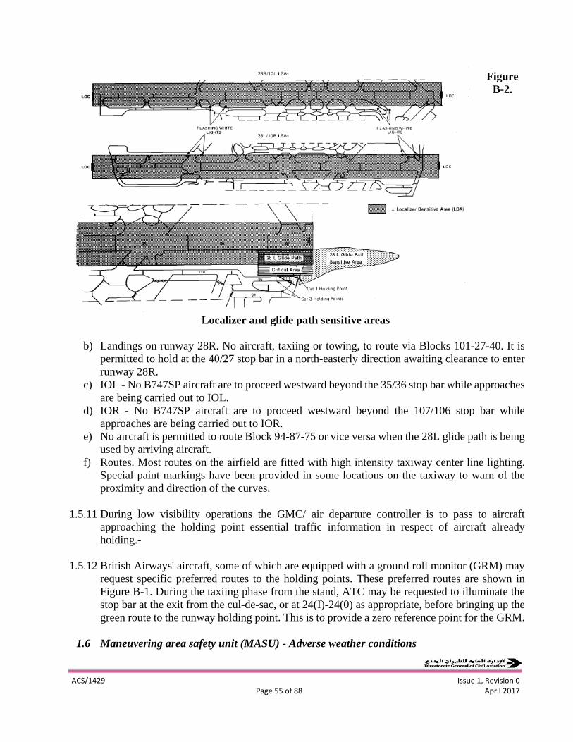
ACS/1429 Issue 1, Revision 0
Page 55 of 88 April 2017
Figure
B-2.
Localizer and glide path sensitive areas
b) Landings on runway 28R. No aircraft, taxiing or towing, to route via Blocks 101-27-40. It is
permitted to hold at the 40/27 stop bar in a north-easterly direction awaiting clearance to enter
runway 28R.
c) IOL - No B747SP aircraft are to proceed westward beyond the 35/36 stop bar while approaches
are being carried out to IOL.
d) IOR - No B747SP aircraft are to proceed westward beyond the 107/106 stop bar while
approaches are being carried out to IOR.
e) No aircraft is permitted to route Block 94-87-75 or vice versa when the 28L glide path is being
used by arriving aircraft.
f) Routes. Most routes on the airfield are fitted with high intensity taxiway center line lighting.
Special paint markings have been provided in some locations on the taxiway to warn of the
proximity and direction of the curves.
1.5.11 During low visibility operations the GMC/ air departure controller is to pass to aircraft
approaching the holding point essential traffic information in respect of aircraft already
holding.-
1.5.12 British Airways' aircraft, some of which are equipped with a ground roll monitor (GRM) may
request specific preferred routes to the holding points. These preferred routes are shown in
Figure B-1. During the taxiing phase from the stand, ATC may be requested to illuminate the
stop bar at the exit from the cul-de-sac, or at 24(I)-24(0) as appropriate, before bringing up the
green route to the runway holding point. This is to provide a zero reference point for the GRM.
1.6 Maneuvering area safety unit (MASU) - Adverse weather conditions

ACS/1429 Issue 1, Revision 0
Page 56 of 88 April 2017
1.6.1 Run way categories
1.6.1.1 Runways 10L, 10R, 28L and 28R are equipped to accept aircraft operations down to ICAO
Category I11 limits.
1.6.1.2 Special procedures have been developed for aircraft operations in low visibility conditions and
are promulgated in the United Kingdom Air Pilot AGA Section.
1.6.2 Localizer sensitive area (LSA) lights and holding points
1.6.2.1 1.6.2.1 The following special facilities are provided for use in low visibility conditions:
a) LSA lights. These are positioned 137 m from the runway center line each side of the taxiway at
the nominated Category 111 turn-offs. The lights are omnidirectional, high intensity flashing
white. They are switched on in low visibility conditions only and provide an indication to the
pilot of an arriving aircraft turning off the runway that the aircraft is clear of the ILS localizer
sensitive area (see the Note below).
b) Category 111 holding points. These are positioned in taxiway Blocks 75, 92, 98, 94, 95 and
115 to keep aircraft awaiting take-off clear of the ILS sensitive areas. They are marked with
standard ICAO Category II/III taxiway point marks, additional runway guard lights switched
on in low visibility conditions only, and illuminated Category II/III notice boards.
Note.- It is anticipated that this facility will be replaced by yellow/green coded taxiway center
line lights to the limit of the LSA.
1.6.2.2 The above facilities are inspected once a week by the MASU and immediate rectification action
taken whenever necessary.
1.6.3 Additional safety precautions – low visibility checklists
1.6.3.1 The following additional precautions are taken to safeguard operations in low visibility.
1.6.3.2 Low visibility Checklist I . Implement when the IRVR is 1 000 m and the forecast shows that
the visibility will fall to below 600 m, or when requested by ATC or the operations duty
manager or ADC.
a) The MASU control room will telephone the following and advise them:
"Preliminary warning - low visibility procedures are expected to be in force shortly."
1) aerodrome fire service watchroom
2) access control duty officer (close controlled crossings)
3) control Post 12
4) operations duty manager (ODM)
5) apron safety unit
ACS/1429 Issue 1, Revision 0
Page 57 of 88 April 2017
6) police
b) Check all the perimeter fencing and access gates including Wessex Road and Viscount Way.
c) Warn and remove maintenance and works contractors as necessary.
d) Check that the "shingals" (Category I11 approach lighting) for the available runways are on
and serviceable.
e) Check that the greedyellow runway turn-off lights are serviceable.
f) Ensure that warning signs and markers are available for Block 27/101 and No. 2 maintenance
area.
1.6.3.3 Low visibility Checklist 2. Implement when advised by ADC that low visibility procedures are
commencing (touchdown IRVR 600 m - cloud base 200 ft or less), or when requested by the
ODM.
a) The MASU control room will telephone the following and advise them that:
"Low visibility procedures are now in force"
1) aerodrome fire service watchroom
2) access control duty officer (close controlled crossings)
3) control Post 12
4) operations duty manager
5) apron safety unit
6) police
b) Switch on all LSA lights at blocks 89, 36, 17 and 75.
c) Switch on all low visibility runway guard lights (taxiholding position lights) and Category II/III
board lights at Blocks 98, 115, 92, 75, 94 and 95.
d) Mark off Block 101/27 stop bar and erect "no entry" sign. (Advise ADC that route 101-27 is
not available.)
e) Check that all controlled crossings are closed.
f) Erect "no entry" signs at entrances to Pan Am, GA apron and fields apron.
g) Advise ADC that low visibility safeguarding has been completed.
1.6.3.4 Low visibility Checklist 3. Implement when advised by ADC that low visibility procedures are
cancelled, or at the request of the ODM.
a) The MASU control room will telephone the following and advise them that: "Low visibility
procedures are cancelled. "
1) aerodrome fire service watchroom
2) access control duty officer
3) operations duty manager
4) apron safety unit
5) control Post 12
6) police.
b) Remove "no entry" signs at Pan Am, GA apron, Block 101 and advise ADC that route 101-27
is available.
c) Switch off all LSA lights.
ACS/1429 Issue 1, Revision 0
Page 58 of 88 April 2017
d) Switch off all low visibility Category II/III board lights.
e) Advise maintenance and works contractors that they may resume operations.
2. FRANKFURT AIRPORT, FRANKFURT, FEDERAL REPUBLIC OF GERMANY
2.1 Introduction *
2.1.1 In 1982 Frankfurt Airport introduced all weather operations down to Category I11 limits of an
RVR of 125 m. At the request of the Federal Ministry of Transport, procedures and measures
for Category II/III low visibility operations have been introduced and in the interests of safety,
all departments, authorities and companies are required to instruct their employees to comply
with these procedures which are contained in Part 11, Chapter 1.1 of the Airport Regulations.
2.2 Category I1 operations
2.2.1 Definition
2.2.1.1 Operations with a high probability of successful approach and landing from a 200 ft (60 m)
decision height and an RVR of 800 m down to a 100 ft (30 m) decision height and an RVR of
400 m.
2.2.2 Operational requirements for Category II
2.2.2.1 Category I1 operations may only take place if Air Traffic Control (ATC) has taken the measures
stated in 2.4 and the following systems and installations are in a "fail-safe" operation:
a) Instrument landing system (ILS)
- localizer
- glide path
Note.- In the event of a failure of the outer marker and/or the middle marker, no downgrading
to a lower approach category shall take place. The failure shall be reported to the pilot who
then is solely responsible for determining his operating minima.
b) Visual aids for landing
- approach lighting system
- runway threshold lights
- runway touchdown zone lights
- runway center line lights
Note.- Failure of visual aids for landing (2 phases or tots[) and failure of the secondary power
supply shall be reported to the pilot immediately.
c) Meteorological installations
- ground wind speed and direction indicators
- -the runway visual range (RVR)

ACS/1429 Issue 1, Revision 0
Page 59 of 88 April 2017
Note.- The above installations shall continuously provide current meteorological data.
d) Secondary power supply for the runway lighting system.
2.2.2.2 The working condition of the individual installations and systems is monitored and shown on
an indicator in the approach control and in aerodrome control.
2.3 Category III operations
2.3.1 Definition
a) Category 111 (a): Operations down to the runway surface, relying on external visual reference
during the final phase of landing and down to an RVR of the order of 200 m.
b) Category I11 (b): Operations down to the runway surface and sufficient visibility for taxiing.
Note.- The minimum visibility in which taxiing can take place without reliance on visual
references (e.g. taxiway center line lights and stop bars) and avoid collision with other traffic
approaching an intersection has been determined as 150 m at Frankfurt Airport.
2.3.2 Operational requirements for Category III
2.3.2.1 Category 111 operations may only take place if the Federal Air Navigation Agency has taken
the measures stated in 2.4 and the following systems and installations are in a "fail-safe"
operation:
a) Instrument landing system ILS
- localizer
- glide path
Note.- See 2.2.2.1 a)
b) Visual aids for landing
- runway threshold lights
- runway touchdown zone lights
- runway center line lights
c) Visual aids for taxiing
- stop bars
- -taxiway center line lights
ACS/1429 Issue 1, Revision 0
Page 60 of 88 April 2017
Note.- Failure of visual aids for landing (2 phases or tots[) and failure of the secondary power
supply shall be reported to the pilot immediately.
d) Meteorological installations
- ground wind speed and direction indicators
- the runway visual range
Note.- The above installations shall continuously provide current meteorological data.
e) Secondary power supply for the runway lighting system
2.4 Measures taken by the Federal Air Navigation Agency (see Figures B-3 to B-5)
2.4.1 Notification
a) Category I1
- If either of the first two transmissometers installed in the landing direction show RVR values
of 1 000 m or less;
- and/or if the ceiling or vertical visibility is reported to be below 300 ft;
- and if the landing weather forecast expects further deterioration of the runway visual range
and/or a further lowering of the ceiling, i.e. further deterioration of the vertical visibility; the
Federal Air Navigation Agency shall give notification to the following offices of the
forthcoming commencement of Category I1 flight operations:
1) meteorological service
2) Flughafen Frank-Main AG (FAG) apron control
3) Rhein-Main military apron control (United States Air Force).
b) Category I11
- If either of the first two transmissometers installed in the direction of landing show RVR values
of 400 m or less;
- and/or if the ceiling or vertical visibility is reported to be below 100 ft;
- -and if the landing weather forecast expects a deterioration of the runway visual range and/or a
lowering of the ceiling or vertical visibility; the Federal Air Navigation Agency shall notify the
following offices of the forthcoming commencement of Category I11 flight operations:
1) Flughafen Frank-Main AG (FAG) apron control
2) Rhein-Main military apron control (United States Air Force).
2.4.2 Procedures
2.4.2.1 The Federal Air Navigation Agency shall check whether the system, installation and indicator
mentioned in 2.2.2 and 2.3.2 are serviceable and in a 'fail-safe" operating condition, and
whether the meteorological service facilities are providing the current data, and whether the
ACS/1429 Issue 1, Revision 0
Page 61 of 88 April 2017
FAG apron control and the Rhein-Main military apron control have given the required report
on obstacle clearance. If all the requirements are met and RVR is 800 m or below and/or the
ceiling is below 200 ft, the Federal Air Navigation Agency will give permission for Category
II/III ILS procedures using the phraseology "Low visibility procedures in operation".
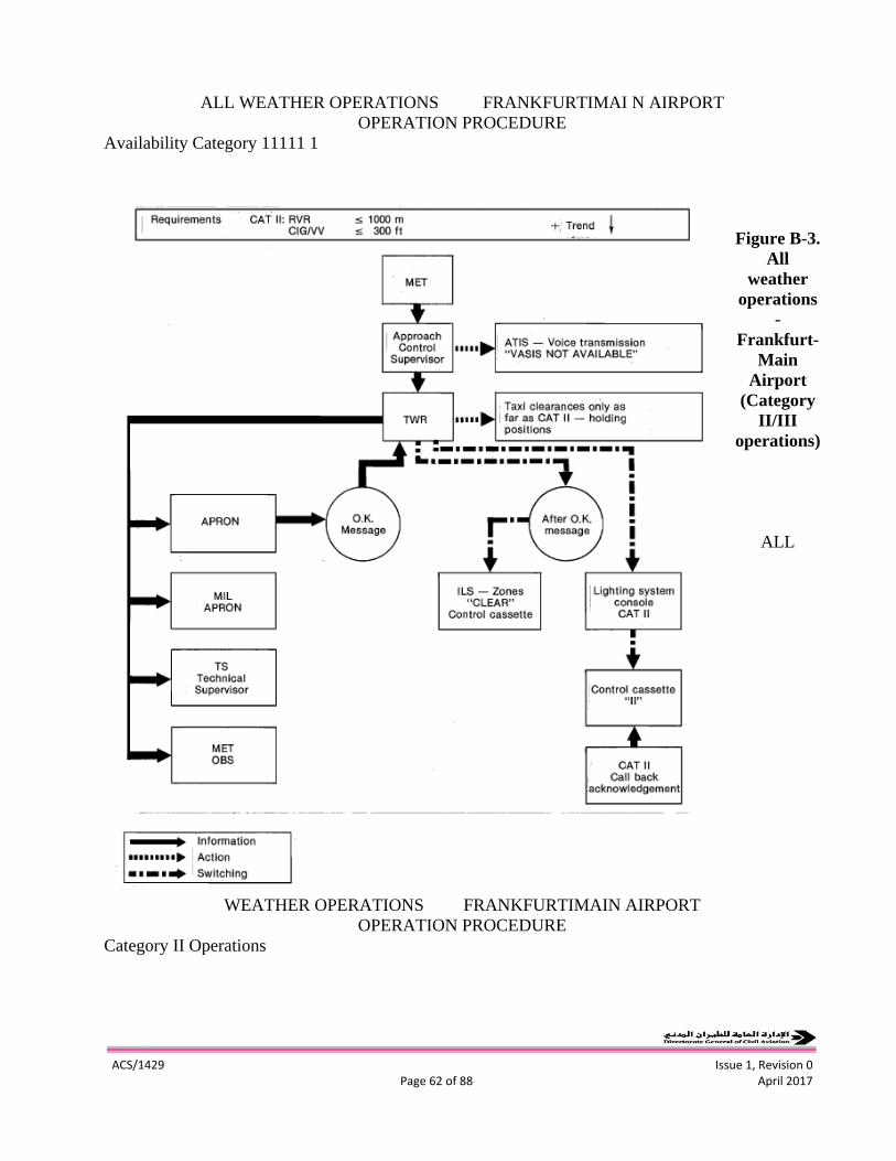
ACS/1429 Issue 1, Revision 0
Page 62 of 88 April 2017
ALL WEATHER OPERATIONS FRANKFURTIMAI N AIRPORT
OPERATION PROCEDURE
Availability Category 11111 1
Figure B-3.
All
weather
operations
-
Frankfurt-
Main
Airport
(Category
II/III
operations)
ALL
WEATHER OPERATIONS FRANKFURTIMAIN AIRPORT
OPERATION PROCEDURE
Category II Operations
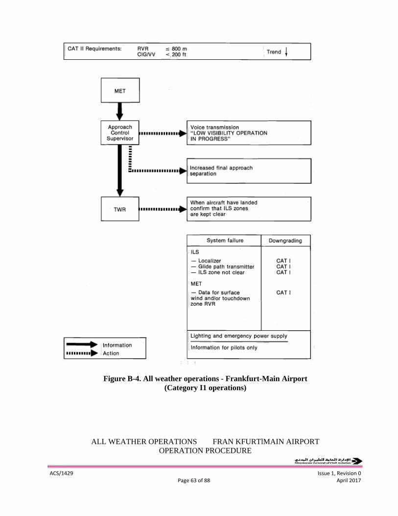
ACS/1429 Issue 1, Revision 0
Page 63 of 88 April 2017
Figure B-4. All weather operations - Frankfurt-Main Airport
(Category I1 operations)
ALL WEATHER OPERATIONS FRAN KFURTlMAIN AIRPORT
OPERATION PROCEDURE
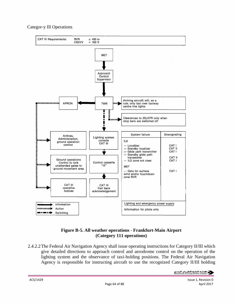
ACS/1429 Issue 1, Revision 0
Page 64 of 88 April 2017
Categor-y Ill Operations
Figure B-5. All weather operations - Frankfurt-Main Airport
(Category 111 operations)
2.4.2.2 The Federal Air Navigation Agency shall issue operating instructions for Category II/III which
give detailed directions to approach control and aerodrome control on the operation of the
lighting system and the observance of taxi-holding positions. The Federal Air Navigation
Agency is responsible for instructing aircraft to use the recognized Category II/III holding
ACS/1429 Issue 1, Revision 0
Page 65 of 88 April 2017
points and if the RVR is 400 m or below and/or the ceiling is below 100 ft for operating the
associated stop bars and taxiway center line lights.
2.4.2.3 The Federal Air Navigation Agency shall also close the service lane to the maneuvering area
by switching the traffic lights to red.
2.4.2.3.1 No aircraft of the type C 5A may be towed within the ILS protection zone on the military
apron without the prior permission of the Federal Air Navigation Agency.
2.4.2.4 The Federal Air Navigation Agency shall terminate Category II/III requirements if, for a period
of at least 20 minutes, the RVR values exceed 1 000 m for Category 11, 400 m for Category
I11 and/or the ceiling or vertical visibility is greater than 200 ft for Category 11, 100 ft for
Category I11 and a trend for further improvement is confirmed by the MET forecaster.
2.5 Aircraft guidance in Category II/III conditions
2.5.1 2.5.1 After landing on the southerly runway (25L/07R) aircraft shall taxi to the apron area
following the green center line lights without the assistance of a "follow me" vehicle. Taxiway
route C(R), W, N should be used after landing on runway 25L and taxiway route C(D), By A
should be used after landing on runway 07R (see Figure B-6).
2.5.2 2.5.2 Clearance to taxi on to the runway for the take-off shall be given by RTF and, in addition,
by switching off the appropriate red stop bar. The stop bar will automatically switch on again
once the aircraft has passed and the controller can check if the stop bar is operating by using
the lighting monitoring system.
2.6 Measures taken by the Rhein-Main military apron control
2.6.1 The Rhein-Main military apron control is responsible for all Category II/IIl requirements within
their area and shall prevent traffic from the south crossing the red line north of the military
apron
1) Clearance of the 300 m strip of all obstacles higher than 15 m (Category 111).
2) Suspension of all traffic, towing and other, on taxiway S.
3) Observance of the recognized Category 11411 taxiholding position on the northern boundary
of the military apron.
4) Observance of the special provisions for the positioning of C5A aircraft in the eastern part of
the military apron.
In the case of an emergency the United States Air Force fire brigade shall assemble at the
Category II/III taxiholding position.
2.7 Measures taken by the German Meteorological Service
2.7.1 The German Meteorological Service shall make routine reports to the competent Federal Air
Navigation Agency office on failures of the meteorological installations serving Category II/III
operations or on their failure probability.

ACS/1429 Issue 1, Revision 0
Page 66 of 88 April 2017
2.8 Measures taken by the airport operator (Flughafen Frank-Main AG - FAG)
2.8.1 Apron control
a) Category I1
When the Federal Air Navigation Agency requests Category I1 readiness, the apron control
shall check and make sure that the ILS sensitivity areas are clear of obstacles (e.g. construction
machinery, vehicles, etc.). Furthermore, it shall stop any uncontrolled traffic on and in the
vicinity of the service lane in the maneuvering area. All traffic in the maneuvering area must
be authorized, i.e. cleared, by the aerodrome control and all vehicle operators shall monitor by
radio the transmitting frequency used by the tower.
Figure B-6. Layout of Frankfurt-Main Airport
The apron control shall increase maneuvering area safety by closing the access from Ellis Road
(i.e. closing the entrance there). Through the security services co-ordination center the apron
control shall give notification of the commencement of Category II/III operations to the fire
and rescue services, the police and to the Federal Border Police.
b) Category I11
In addition to the measures required for Category I1 operations, in Category I11 conditions the
apron control shall instruct the security services coordination
ACS/1429 Issue 1, Revision 0
Page 67 of 88 April 2017
center to check and make sure that all unattended entrances to the maneuvering area are closed.
The security services co-ordination center shall then report to the Federal Air Navigation
Agency via apron control that the measures have been completed. The commencement of
Category I11 operations shall be reported to airline operators, departments, authorities and
companies and other operational control services through the "FAG TV Info" system.
Aircraft guidance in Category 11/111 conditions
- Arriving aircraft shall be guided on the apron area by a "follow me" vehicle in Category I11
conditions from no later than the end of the existing taxiway center line lights.
- "Follow me" vehicles shall guide outbound taxiing aircraft to the agreed transfer-of-control
points.
- In Category I11 conditions, vehicles guiding aircraft must not proceed faster than a maximum
speed of 20 km/h
2.8.2 Aviation supervisory office – general aviation terminal
2.8.2.1 The Aviation supervisory office shall provide appropriate information on Category 111
meteorological conditions at the general aviation terminal entrance to the apron.
2.8.3 Fire fighting services, rescue services and ice and snow removal services
2.8.3.1 In the case of an emergency the fire brigade, rescue and snow/ice removal service vehicles shall
assemble at the recognized Category II/III taxi- holding positions.
2.8.4 Security services
2.8.4.1 The security services shall make sure that all unattended entrances to the maneuvering area are
closed and shall report to apron control that this action is complete. They shall also monitor the
remaining access ways to the operational area and advise the appropriate users. Apron control
shall notify the users of Category I11 operations on the "FAG TV Info" system.
2.8.4.2 Apron control shall notify the security services co-ordination center of Category I11 operations
who, in turn, shall notify all attended apron entrances and other airport agencies of the
commencement of Category I11 operations. The apron entrance attendant shall inform all
vehicles entering the apron area of the Category I11 conditions with reference to the Category
II/III operational procedures and to Section 7 of the Rules of Conduct and Other Provisions
Governing the Traffic in the Maneuvering Area and on the Apron.
2.8.5 Aircraft handling control and other operations control units
2.8.5.1 The individual operations control units shall notify their staff working on the apron of the
commencement and termination of Category 111 conditions and draw their attention to the

ACS/1429 Issue 1, Revision 0
Page 68 of 88 April 2017
Category II/III operational procedures, especially to Section 7 of the Rules of Conduct . . . etc..
, .
2.9 Measures taken by the airline operators, fuelling contractors, agencies and other companies
2.9.1 Airline operators, fuelling contractors, agencies and other companies shall guarantee
compliance with the provisions stated in Section 5.4, paragraph 1 of the Airport Instructions.
They shall ensure that their drivers and pertinent personnel have been given prior notification
of existing Category I11 conditions and are familiar with the Traffic Rules and Licensing
Regulations and with the particular requirements for Category I11 operations.
2.10 Rules of conduct and provisions governing the rraffic in the maneuvering area and on the
apron
2.10.1 General
2.10.1.1 The provisions of Section A of the Traffic Rules and Licensing Regulations shall apply to all
traffic on the maneuvering area and on the apron in all weather conditions:
1) all vehicle operators or other persons using the nonpublic operational areas must be familiar
with the safety regulations, the Traffic Rules and Licensing Regulations and be authorized to
use the non-public operational areas;
2) there is a closed roadway system running through the entire movement area of Frankfurt
Airport. All persons driving on the operational areas must closely follow these roadways,
service lanes and passageways. Information concerning such movement is contained in
Information Sheet 10 of the Traffic Rules and Licensing Regulations.
2.10.2 During Category II/III meteorological conditions
2.10.2.1 In adverse weather conditions more stringent safety regulations and traffic rules shall
apply as follows:
1) no vehicle shall cross a taxiway unless it cannot avoid doing so. Tunnels and bypasses around
taxiway intersections shall be used;
2) in Category II/III conditions, no vehicular traffic shall be allowed on the maneuvering area.
With the commencement of Category I1 conditions all traffic lights on the service lane parallel
to taxiway C shall be switched to red. All traffic must stop immediately and vehicle operators
must contact the Federal Air Navigation Agency aerodrome control on the telephone installed
at each of the traffic lights and request further instructions.
Vehicles authorized by aerodrome control to operate on the maneuvering area in Category II/III
conditions shall permanently monitor the ground control frequency.
2.10.3 During Category 111 meteorology conditions
1) No vehicle may operate on the apron in Category I11 conditions unless urgently needed for the
purpose of handling, fuelling, catering and maintenance. The decision on whether a vehicle is
required shall be made by the respective operations control units. Other traffic shall require
prior permission of the apron control.
ACS/1429 Issue 1, Revision 0
Page 69 of 88 April 2017
2) In Category II/III conditions, aircraft on the apron area shall be guided by a "follow me" vehicle.
3) Notification of Category I11 conditions must be given on the "FAG TV Info" system and by
special signs at the entrances and roadways on the apron.
3. PARIS/CHARLES-DE-GAULLE AIRPORT, PARIS, FRANCE
3.1 Introduction *
3.1.1 Since its opening to traffic in 1974 Paris/ Charles-de-Gaulle has been equipped for Category
I11 operations. The experience gained at Paris-Orly Airport since 1968 was useful in
developing the procedures detailed below.
3.2 General
3.2.1 Four runways are equipped for Category I11 operations (see Figure B-7). ILS runways 09, 10
and 27 are approved for all Category I11 operations; ILS 28 is approved for Category I11 with
decision height not below 15 m (50 ft).
3.2.2 Because of overlapping of categories according to different types of aircraft, only two cases are
considered:
- Category 11: RVR below 800 m but not below 400 m;
- Category 111: RVR below 400 m.
3.3 Equipment to be operating when RVR decreases below 800 m
3.3.1 Lighting. Switch on at maximum intensity:
- runway threshold and end lights;
- runway edge lights;
- runway center line lights;
- touchdown zone lights;
- approach lights;
- high speed turns off center line light;
- taxiway center line lights.
No adjustment of lighting controls is allowed during final approach of aircraft. Lighting
controls must be locked.
3.3.2 ILS. All the elements of ILS used must be operative:
- localizer;
- glide path;
- outer marker
- middle marker.

ACS/1429 Issue 1, Revision 0
Page 70 of 88 April 2017
Figure B-7. Layout of ParidCharles-de-Gaulle Airport
Any maintenance action on ILS is strictly prohibited during the approach. Accordingly, radio-
aids maintenance shall be advised when RVR decreases below 800 m.
3.3.3 Transmissometers. Touchdown and midrunway transmissometers must be operative with direct
reading at control positions.
3.3.4 Control positions organization. As soon as RVR decreases below 800 m a second tower
frequency shall be operative:
- runway 09/27: TWR 1 119.250 MHz;
- runway 10/28: TWR 2 120.650 MHz.
3.3.5 Rescue and fire fighting service. The rescue and fire fighting service shall be on alert position
until weather conditions improve.
3.3.6 Turboclair. As soon as RVR is below 400 m the fog dispersal system (FDS) Turboclair installed
on runway 09 shall be in operation if wind and temperature are within prescribed limits.
ACS/1429 Issue 1, Revision 0
Page 71 of 88 April 2017
3.4 Control procedures
3.4.1 RVR. Touchdown zone and mid-runway RVR values must be given to all aircraft on approach
and tower frequencies. All significant changes are given. Stop end RVR is given if the value is
far below the others. Except in case of worsening conditions, no RVR report is given to an
approach aircraft after the outer marker. When Turboclair is on power, for aircraft using it,
tower controller replaces touchdown RVR value by "FDS".
3.4.2 ATIS
3.4.2.1 RVR. No RVR is given on ATIS; the following phrases are broadcast: "RVR available on
control frequencies. Check your minima".
3.4.2.2 Turboclair. The availability of Turboclair for approved operators is broadcast.
3.4.2.3 Downgrading of runway category. The following advice is broadcast: "Runway (number) not
available for Category I11 (or 11)".
3.4.3 Phraseology and alarm
3.4.3.1 Phraseology. All Category I1 or I11 approaches must be announced by the pilot. The controller
shall ask for a report:
- over outer marker;
- on the runway or going around.
3.4.3.2 Alarm. When final approaches and landings are not visible from tower, red alarm (real accident)
shall be initiated for all radio communication failures following a loss of radar contact
(surveillance radar, surface movement radar) or abnormal moving on these equipments.
3.4.4 Transponder. The switching to stand-by position shall be requested after landing only.
3.4.5 Localizer sensitive area. The ILS signal is protected if aircraft stop at Category I11 taxi-holding
positions.
3.5 Special action
3.5.1 Action by supervisor
3.5.1.1 When RVR is below 800 m:
- open a second tower frequency;
- check that lighting is correctly selected and operating properly;
- check locking of lighting controls;
- check ILS status;
ACS/1429 Issue 1, Revision 0
Page 72 of 88 April 2017
- check transmissometers;
- check ATIS broadcast;
- advise: power-station supervisor;
radio aids maintenance supervisor;
rescue and fire fighting service;
movement area surveillance supervisor;
- check Turboclair condition and prepare starting when RVR falls below 600 m.
3.5.1.2 When RVR is below 400 m, if FDS is operating:
- -operate the runways facing east (except if it is impossible because of wind, equipment failure,
etc.);
- start Turboclair on idle power if users are expected.
3.5.2 Action by approach controllers
- give RVR at touchdown and mid-runway;
- respect prescribed spacings;
- -transmit to tower all requests for Category 11, Category I11 or Turboclair;
- vector at moderate speed (180 kt at 15 NM from touchdown);
- intercept localizer at 15 NM from touchdown and hand over to tower at that distance.
3.5.3 Action by tower controllers
- give RVR;
- respect prescribed spacings;
- check ILS condition;
- -switch Turboclair power on for aircraft using it and switch off after landing;
- use only approved phraseology;
- do not allow an aircraft to enter localizer sensitive area during approaches;
- -initiate alarm according to 3.4.3.2;
- -inform pilots of all failures of ILS, lighting or Turboclair;
- give Turboclair cross wind if any;
- use surface movement radar to monitor runways.
3.5.4 Action by ground controller
- -hand over to tower only one aircraft at a time when at the taxi-holding position, and when clear
of any preceding traffic;
- use surface movement radar to monitor carefully all taxiing aircraft;
- use surface movement radar to monitor vehicles allowed to travel on maneuvering area for
safety reasons (ATS vehicles, urgent maintenance, rescue and fire fighting service).
ACS/1429 Issue 1, Revision 0
Page 73 of 88 April 2017
Appendix C
Examples of Apron Management Services
1. HEATHROW AIRPORT, LONDON, UNITED KINGDOM
1.1 Traffic 1983/84
Passengers 26 749 200 (84 per cent international)
Air transport movements 260 100
Cargo (tonnes) 469 700
1.2 General. The airport is owned and operated by the British Airports Authority and the air traffic
control service is provided by the National Air Traffic Services of the Civil Aviation Authority.
1.3 Layout. Three passenger terminals are located in the center of the airport, and are served by a
total of eight piers which are surrounded by 116 aircraft stands. On the south side of the airport
is a large cargo terminal which has a further 25 stands. A fourth passenger terminal is under
construction which will have a further 22 stands.
1.4 Stand guidance. The majority of stands are equipped with azimuth guidance for nose-in stands
(AGNIS), complemented by parallax parking aid (PAPA) or side marker boards. The airport
authority provides a marshalling service for the remaining stands.
1.5 Apron maintenance. The apron areas have their own management organization responsible to
the chief of airside safety and operations. Staff of the apron safety unit inspect all aprons
regularly, as do members of operations management, and defects are reported to airport
engineers for maintenance or repair. Stands are swept by sweeper vehicles when required and,
in addition, there is a regular programme for the stands to be wet-scrubbed. Fuel spillages are
reported to the apron safety unit who arrange for the cleaning.
1.6 Visual aids. All aircraft stands have standard paint markings and all apron taxiways have
switchable green center line lights and stop bars. Most aircraft stands have yellow aircraft stand
maneuvering guidance lights. Aprons are marked in white paint to delineate equipment areas,
inter-aircraft stand clearways and airside roads. The boundary between the aircraft stands and
the taxiway is indicated by a continuous double white line. This line is also the boundary
between the maneuvering area and the apron area.
1.7 Air traffic control. All movements on the airport except vehicles on aprons are controlled by
the air traffic control service. As soon as aircraft are pushed back onto the taxiway they are on
the maneuvering area and are controlled by the ground movement controller. Having the
maneuvering area boundary between the stands and the apron taxiway has proved very
successful, not only at Heathrow, but at other major British airports. The air traffic control
service exercises positive R/T control over all movements on the apron taxiways. This provides
high standards of discipline on apron taxiways and also means that the apron management
service does not need to employ licensed controllers to exercise control over aircraft
movements in the apron area.

ACS/1429 Issue 1, Revision 0
Page 74 of 88 April 2017
1.8 Apron control. The apron control room is staffed by employees of the airport authority. Apron
control is the focus for information on arriving and departing aircraft and is responsible for the
allocation of the majority of aircraft stands at the airport. The allocation of aircraft stands
serving one of the central area terminals is delegated to British Airways. Apron control staff
have no direct communication with aircraft and all information is passed through the ground
movement controller in the tower.
1.9 Low visibility procedures. As the apron area comprises only aircraft stands there is very little
involvement in low visibility procedures. Low visibility operations safeguarding is carried out
on the maneuvering area by another unit of operations staff.
Apron staff close certain vehicle crossings on taxiways and provide a "follow me" service as
required.
2. ZURICH AIRPORT, ZURICH, SWITZERLAND
2.1 Traffic 1985
Passengers 9 546 600 (95 per cent international)
Air transport movements 128 230
Cargo (tonnes) 210 750
2.2 General. The airport is owned by the Canton of Zurich and operated by the Zurich Airport
Authority. Air traffic control services are provided by a private company under contract to the
Federal Government with the exception of the apron unit which is controlled by the airport
authority.
2.3 Layout. The apron area is a compact triangular shape and lies in the segment southeast of the
intersection between runways 28 and 34. The area is served by two adjacent passenger terminals
and a large freight building. One passenger terminal has a finger pier with nine aircraft stands.
A second pier is at present being built on the other passenger terminal. The apron comprises 51
stands plus five sectors for general aviation traffic.
2.4 Stand guidance. The pier stands of terminal (A) are equipped with the Swedish Safe Gate
System, those of terminal (B) with PAPA/AGNIS systems. The remote stands have painted
surface markings so that aircraft can self-position and stop without assistance. Marshallers are
used only in special cases or extraordinary operating conditions.
2.5 Apron maintenance. Airport operations staff inspect the surfaces of the movement area three
times daily for serviceability and cleanliness. Any problems are reported to airport maintenance
staff. The maintenance staff carry out their own detailed inspection of surfaces two times daily.
Maintenance staff are responsible for the cleanliness of the parking stands. Cleaning vehicles
are in constant use and stands are regularly vacuum cleaned.
ACS/1429 Issue 1, Revision 0
Page 75 of 88 April 2017
2.6 Visual aids. Standard yellow taxiway markings are used with blue edge lights. A system of
selectively switchable green center line routes and stop bars is soon to be installed.
2.7 Air traffic control. Control of air traffic on the maneuvering area is exercised by the air traffic
control service. Control of air traffic on the apron area is exercised by a separate unit called
apron control (airport authority). The maneuvering area boundary with the apron control area
of responsibility is delineated by various grass areas and standard taxiholding position markings
on those taxiways which link the apron area with the two adjacent runways.
2.8 Apron control. Within its area of responsibility, apron control aims to prevent collisions
between aircraft and between aircraft and obstacles. It is also responsible for an orderly and
expeditious flow of traffic on the apron taxiways and the aircraft stands taxilanes plus the
allocation of parking stands. Apron controllers are employees of the airport authority. Their
training follows a programme worked out by the air traffic control service and airport authority
under the supervision of the Federal Office for Civil Aviation, after which they must obtain and
maintain an apron controller's licence issued by the Federal Office for Civil Aviation. Aircraft
request start-up clearance from air traffic control (clearance delivery) and then change to apron
control frequency for pushback/tow out/taxi clearances. Aircraft are then retransferred to the
air traffic control frequency at the maneuvering area boundary. Similarly, inbound aircraft are
transferred from air traffic control to apron control at the maneuvering area boundary.
2.9 Low visibility procedures. Aircraft are guided with the assistance of marshallers and "follow
me" vehicles. The need for this service will cease when the ground movement control taxiway
lighting is installed together with surface movement radar. Casual maintenance work on the
maneuvering area ceases when the visibility falls to 2 500 m unless authorized airport
operations staff are in attendance.
3. MELBOURNE INTERNATIONAL AIRPORT, MELBOURNE, AUSTRALIA
3.1 Traffic 1983/84
Passengers 5 405 600 (17 per cent international)
Air transport movements 68 900
Cargo (tonnes) 107 200
3.2 General. The airport is owned and operated by the Australian Department of Aviation. Airport
administration and apron management are the responsibilities of the airport director. The air
traffic control service is also provided by the department of aviation but it is not within the
jurisdiction of the airport director.
3.3 Layout. The airport has one large terminal in which the central portion and associated pier
handles international traffic. The two wing portions, and associated piers, are each allocated to
a major domestic airline and handle all domestic traffic. There are approximately 25 stands

ACS/1429 Issue 1, Revision 0
Page 76 of 88 April 2017
around the three piers serving the terminal. There are two separate freight aprons allocated
mainly one each to the domestic airlines.
3.4 Aircraft stand guidance. Most aircraft stands are equipped with nose-in guidance systems with
side marker boards and side marker lights. The Department of Aviation (D of A) provides
marshallers who mainly perform their duties on the D of A apron areas. Various major airlines
provide their own marshallers.
3.5 Apron maintenance. Operations staff, under the airport director, are responsible for regular
inspections of the movement area and any repairs are carried out by airport maintenance staff.
Cleanliness of the aircraft stands is a responsibility shared by the Airline Operators Committee
and the airport staff. The D of A operates a mobile mechanical sweeper on the apron area and
the state of cleanliness is monitored by both airline and airport staff. Fuel spillages are the
responsibility of the airline concerned; however, they may request assistance through the
surface movement controller (aprons) of the airport ground staff and the rescue and fire fighting
service.
3.6 Visual aids. Apron surface markings comprise aircraft parking guidelines to provide pilots with
guidance from taxiways onto the aircraft stand and aircraft parking limit lines to ensure taxi
lanes are not infringed by parked aircraft. Equipment parking areas, equipment limits and
airside vehicle roads are also delineated on the apron.
3.7 Air traffic control. Activity on the apron area is controlled by a surface movement controller
(aprons) from a small control tower overlooking the apron. This controller holds a current air
traffic control licence and is also therefore able to exercise control over part of the maneuvering
area. He is responsible for co-ordinating movements on the apron area. There is a geographical
boundary between the area of responsibility of the surface movement controller (aprons) and
the surface movement controller responsible for activity on the maneuvering area. However,
the boundary is not marked by any painted lines or signs but is associated with a frequency
change directed by the controller.
3.8 Apron control. An apron co-ordinator works closely with the surface movement controller
(aprons) and is responsible for allocating international parkingbays, baggage carousels, and for
policing the occupancy of parking bays. Each domestic airline has an operating center from
which it exercises responsibility for the usage of its own apron area including the allocation of
parking bays. The apron co-ordinator has no direct communication with aircraft and passes
information through the surface movement controller (aprons).
3.9 Low visibilityprocedures. There are no special low visibility operations procedures for the
apron area. The airport safety officers generally police the movement of vehicles on the apron
areas and will provide a "follow me" service if required.
4. FRANKFURT-MAIN AIRPORT, FRANKFURT, FEDERAL REPUBLIC OF
GERMANY
4.1 Traffic 1984
ACS/1429 Issue 1, Revision 0
Page 77 of 88 April 2017
Passengers 19 03 1 764 (74 per cent international)
Air transport movements 214 954
Cargo (tonnes) 772 787
4.2 General. The airport is owned and operated by Flughafen Frankfurt-Main AG. The air traffic
control service is provided by the Federal Administration of Air Navigation Services of the
Federal Republic of Germany.
4.3 Layout. The airport has a central passenger terminal with four finger piers surrounded by 36
aircraft stands. One finger (C-Finger) will be enlarged in 1987 with five additional aircraft
stands. The apron comprises a maximum of 82 aircraft stands plus a general aviation apron on
the east side of the airport. On the west side there is a large cargo terminal which has 16
additional aircraft stands.
4.4 Stand guidance. The majority of aircraft stands are equipped with AGNIS, complemented by
PAPA, so that the aircraft can self-position and stop without assistance. The airport operator
provides a marshaling service for the remaining aircraft stands.
4.5 Apron maintenance. The apron area has its own management organization responsible to the
chief of airside operations. Staff of the apron operation units inspect all areas of the apron
regularly. Defects are reported to airport engineers for maintenance or repair. Aircraft stands
are swept by sweeper vehicles when required and in addition, there is a regular programme for
the stands to be wet-scrubbed. Fuel spillage is reported to the apron operation units who arrange
for cleaning.
4.6 Visual aids. Standard yellow taxiway markings are used and, where they are necessary, edge-
lights. Likewise all aircraft stands have standard paint markings. A system of green center line
lights, stop bars and clearance bars on the apron and the maneuvering area is partly installed
and will be developed over the next few years.
4.7 Air traffic control. Aircraft movements on the maneuvering area are controlled by the Federal
Administration of Air Navigation Services. Aircraft movements on the apron area including
apron taxiways are controlled by the airport operator (FAG apron control), the "apron
management unit".
4.8 Apron control. Within its area of responsibility, apron control aims to prevent collisions
between aircraft and between aircraft and obstacles. It is also responsible for an orderly and
expeditious flow of traffic on the apron including the allocation of parking stands. Apron
controllers are employees of the airport operator. Their training follows a programme worked
out by the air traffic control service and the airport operator. Apron controllers have to obtain
a federal flight radiotelephone operator's certificate. Aircraft request start-up clearance from air
traffic control and then change to apron control frequency for pushbackkaxi instructions.
Aircraft are then transferred to air traffic control at the maneuvering area boundary. Similarly,
inbound aircraft are transferred from air traffic control to apron control at the maneuvering area
boundary.
ACS/1429 Issue 1, Revision 0
Page 78 of 88 April 2017
4.9 Low visibility procedures. Aircraft guidance during low visibility operations is supported by
predetermined taxi routes. Most of these standard taxiways are equipped with green taxiway
center line lights. On taxiways without center line lights aircraft are guided by the assistance of
marshallers and "follow me" vehicles. The need for this service will cease when the ground
movement control taxiway lighting is installed together with surface movement radar.
Uncontrolled vehicular traffic on the movement area is prohibited when the visibility falls
below 1 000 m.
5. PARIS/CHARLES-DE-GAULLE AIRPORT, PARIS, FRANCE
5.1 Traffic 1984
Passengers 13 966 543 (89 per cent international)
Air transport movements 133 503
Cargo (tonnes) 506 440
5.2 General. The airport is owned and operated by Aeroports de Paris. Air traffic control is
provided by the French Ministry in charge of civil aviation.
5.3 Layout. The airport has two passenger terminals located in the center of the airport. Terminal
No. 2 is currently being extended. A large cargo terminal is located south-west of the airport.
There are 153 aircraft stands on the airport, 118 of which can be
5.4 used simultaneously.
5.5 Stand guidance. All stands have painted surface markings. Stands of Terminal No. 2 have a
visual docking guidance system. Marshaller service is available from the airport operator and
major airlines. This service is provided to all aircraft using Terminal No. 1. At Terminal No. 2
this service is provided only on request.
5.6 Apron maintenance. The airport operator is responsible for regular inspections and repairs of
the apron. Periodically stands are wet-scrubbed. Fuel spillages are the responsibility of the
airlines and fuelling companies. They may request the assistance of the airport operator and of
the rescue and fire fighting service in case of a large spillage.
5.7 Visual aids. Standard yellow taxiway markings are used to provide guidance to pilots onto the
parking stands. White painted lines delineate equipment parking areas, airside vehicle roads
and the boundary between aprons and the maneuvering area.
5.8 Air traffic control. All movements on maneuvering area are controlled by air traffic control -
service. If pushback will engage a taxiway, ground movement controller approval is required
and is given according to aircraft movements only.
5.9 Apron management. Paris Airports Authority dispatch (PCO) is responsible for apron
management. PC0 staff have no direct communication with aircraft. Stand allocation is given
via television and strip printer to ground controller who retransmits to aircraft. Manoeuvres
inside apron limits are made under operator's responsibility according to established rules.

ACS/1429 Issue 1, Revision 0
Page 79 of 88 April 2017
5.10 Low visibility procedures. There are no special low visibility procedures for operations on
apron areas. However, exterior lights of aircraft and vehicles should remain on and
pilots/drivers are expected to exercise due care and caution.
ACS/1429 Issue 1, Revision 0
Page 80 of 88 April 2017
Appendix D
Taxiway Computer Model London Heathrow Airport
1. INTRODUCTION
1.1 The following is a brief description of the taxiway computer model developed in 1971 to assess
the effects of major changes in the taxiway system and/or operations to ground movement
control at London Heathrow Airport. It has been successfully used to show the effects of major
new airport features such as terminal buildings, new taxiway construction and changes in
aircraft types. Even though only one airport, Heathrow, has been modelled, the programme can
be adapted to simulate any airport and be interfaced with a runway model to complete a total
simulation of ground operations.
1.2 The model will be in need of major modifi- cation by 1988 and, because of its complexity, it is
possible that a decision will be made not to carry out any changes and consequently the model
will become redundant.
2. THE TAXIWAY MODEL
2.1 The consists five programmes. The linkages between these programmes are in Figure D-l and
their functions are outlined below based on the block system of control in use at Heathrow (see
Au~endix B. Figure B-1.mar, of Heathrow).
2.1.1 Traffic schedule generation programme. This programme generates a traffic schedule based on
the total number of aircraft expected to arrive and depart in each time ~eriod together with the
percentage of each aircraft type expected to operate. The schedule is generated randomly taking
account of the maximum percentage of each aircraft type, and aircraft are assigned to a
particular operator based on the per- centage fleet mix of each airline. Arrivals are given an
expected time of arrival chosen randomly taking no account of any inter-arrival spacing.
Departures are given a scheduled departure time based on the per- centage of departures
scheduled to depart at set times in each hour.
2.1.2 Route and stand storage programme. This programme stores information about aircraft stands
on the airport, and the routes to and from these aircraft stands for both arriving and departing
aircraft. Any combination of aircraft type and operator can be allocated to a group of aircraft
stands and aircraft are allocated randomly to these on the basis of given percentages. Taxi routes
are stored between all runway turn-off blocks and each aircraft stand or group of aircraft stands
and similarly between the stands and the runway start of roll blocks. Routes are given as
standard routes and, where possible, the preferred shortest routes are used.
2.1.3 Route and time generation programme. This programme combines a traffic schedule, derived
either from the traffic schedule generation programme or from specific data input from the route
and stand storage programme. Inbound aircraft are allocated to runway turn-off blocks based
on percentage distributions for each aircraft type and operator requirements. Stand or stand
groups are also allocated at this stage, hence the aircraft's basic route around the taxiway is
determined. Arrival times of aircraft onto the taxiway at the point of leaving the runways are
staggered to give at least some minimum inter-arrival spacing regardless of aircraft type.
Departure times of aircraft are also staggered from those scheduled, to take account of any
company or ATC delays due to congestion that are absorbed on the stand prior to pushback. l-
ACS/1429 Issue 1, Revision 0
Page 81 of 88 April 2017
he output from the programme is a list of aircraft with their associated routings and their arrival
times onto the taxiway ready for the simulation programme itself.
2.1.4 Simulation programme. This is a "critical event" simulation programme which moves from one
particularly important or critical event to the next rather than sampling at fixed time intervals.
It does not look indefinitely ahead but the situation on the taxiways is considered at the time of
each critical event and any route adjustments made accordingly. A "critical event" is defined as
when an aircraft enters or leaves the taxiway system or when a conflict occurs between two
aircraft on a particular taxiway. Between these "critical events" aircraft move continuously
through the taxiway system at a randomly determined speed based on aircraft type. Journey
times are calculated on the basis of block length information input to the model
Figure D-1. Linkages between the programmes of the mode
2.1.5 The taxiway system is taken to include all blocks on an outbound aircraft's route from the
completion of pushback to entering the runway holding queue for a departure. All holding is
considered to take place in the last block of the aircraft's route and this is not counted towards
aircraft journey time. For inbound aircraft the taxiway system includes all blocks from the first
block on clearing the runway up to and including the block (or cul-de-sac where appropriate)
before entry onto the stand.
ACS/1429 Issue 1, Revision 0
Page 82 of 88 April 2017
2.1.6 The simulation programme moves aircraft around the taxiway with regard to these critical
events, noting the time of entry and exit from the system. For outbound aircraft the runway start
of roll time is also calculated. Conflicts en route are noted as one of five types:
crossing/following, following, crossing, head-on and head-on/crossing. The mode of resolution
by stopping, slowing down or re-routing is also noted in the block on which it occurs along
with the delay to the aircraft. RT messages and the duration of these messages are counted over
set time periods. These messages consist of standard messages when the aircraft enters or leaves
the taxiway and specific messages relating to conflict resolution or runway crossing plus some
miscellaneous messages. This information is output by aircraft and taxiway block such that it
can be read by the analysis programme.
2.1.7 Analysis programme. This programme presents the output from the simulation as a series of
summary tables. Journey summaries for individual aircraft may also be obtained. The tables
give information about aircraft journey times and taxiing delays, stand complex and runway
holding delays, numbers of aircraft on the taxiway and in the runway holding queue, movement
rates through the taxiway blocks and numbers of conflicts requiring resolution, numbers and
lengths of RT messages and total conflict counts by type.
Appendix E
Traffic Rules and Regulations for Surf ace Vehicles
1. Rules for the regulation of aircraft movements on the ground are contained in KCASR 2 and
in the PANS-RAC, but equivalent rules for use by ground vehicles also need to be provided
and enforced. At aerodromes without an air traffic control service, the rules and the need for
strict adherence to these rules becomes even more important.
2. Except in very poor visibility conditions when special low visibility procedures should apply
ACS/1429 Issue 1, Revision 0
Page 83 of 88 April 2017
(see Chapter 5), it is not always practicable to exercise total control over all traffic on parts of
the movement area such as the apron. Within the field of reasonable constraint according to
conditions authorized in other parts of this manual, safety and expedition depends upon aircraft
and vehicles conforming to standard ground movement rules and regulations. Appropriate
authorities should establish suitable rules related to the operation of aircraft and ground vehicles
on the movement area.
3. The rules and regulations for the ground movement of vehicles should encompass at least the
following points.
General
4. The movement area should be fenced or otherwise protected against unauthorized entry and
should be provided with controlled entry points. Only vehicles and/or equipment which have a
specific and necessary function to perform in connexion with aircraft or aerodrome facilities
should be granted admission to the movement area. Authorized drivers should carry a pass.
Vehicles cleared for entry should clearly be identified as authorized to be there by having an
approved identification token prominently displayed.
Requirements for authorized vehicles and/or equipment operators
5. A vehicle operator SHALL:
a) be knowledgeable of local rules and regulations or be escorted by a person who is conversant
with them;
b) be capable of distinguishing between visual signals;
c) give way to aircraft at all times;
d) obtain ATS clearance prior to entering the maneuvering area and comply with the terms and
limitations of the clearance;
e) follow specified routes and guide lines and not encroach upon safety lines;
f) approach aircraft with utmost care, particularly if aircraft engines are running and/or anti-
collision lights are operating;
g) obey movement area speed restrictions;
h) where appropriate, be experienced in the operation of RTF equipment and capable of correctly
reacting to RTF messages;
i) where appropriate, maintain a continuous listening watch on the ground movement control
radio channel, requesting ATS clearance as required by aerodrome regulations and complying
with ATS instructions; and
j) be familiar with the aerodrome layout and the signs and signals used on the aerodrome.
6. A vehicle operator SHALL NOT:
a) position a vehicle so as to interfere with the movement of aircraft;
b) pass close behind an aircraft if its engines are running and its anti-collision lights operating, or
position a vehicle in a jet blast or propeller slipstream;
c) cross traffic control signals, stop bars or markings without appropriate authorization;

ACS/1429 Issue 1, Revision 0
Page 84 of 88 April 2017
d) leave a vehicle unattended where it may create a hazard; and
e) Operate a vehicle during the hours of darkness or periods of restricted visibility unless it is
equipped with suitable lighting (see paragraph 7 below).
Requirements for vehicles and/or equipment
7. Vehicles and equipment SHALL BE:
a) marked and lighted as per KCASR 14, Chapter 6; and
b) Fitted with front and rear lights in accordance with local regulations if operated during the hours
of darkness or during periods of restricted visibility.
8. Trailer trains must not exceed the length specified by the aerodrome authority and must have
adequate braking systems. They must carry red reflectors at the rear and along the sides as
appropriate if used in low visibility or at night.
Appendix F
Performance Objectives for Surface Movement Radar (SMR)
1. INTRODUCTION
1.1 The purpose of providing SMR is to aid the air traffic services in achieving their objectives as
defined in KCASR 11. These objectives are:
a) to prevent collisions between aircraft;
b) to prevent collisions between aircraft on the maneuvering areas and obstructions in those areas;
c) to expedite and maintain an orderly flow of traffic;
ACS/1429 Issue 1, Revision 0
Page 85 of 88 April 2017
d) to provide advice and information useful for the safe and efficient conduct of flight; and
e) to notify appropriate organizations regarding aircraft in need of search and rescue aid, and assist
such organizations as required.
1.2 At an aerodrome adequately equipped with visual aids, the provision of an aerodrome surface
movement radar can make a valuable contribution to the safety and efficiency of ground
movement control in reduced visibility and at night. Surface movement radar permits a
continuous check on runway occupancy and taxiway usage, allows rapid determination of
lighting control requirements and facilitates clearances for aircraft and vehicles. In emergencies
it can play a part in the expeditious movement of emergency vehicles and the safe disposition
of other traffic.
2. USE OFSMR
2.1 As described in the Air Traffic Services Planning Manual (Doc 9426), Part 11, Section 5,4.3.2,
SMR may be used to perform the following functions specifically related to the provision of
aerodrome control service:
a) provide radar monitoring of traffic on the maneuvering area;
b) provide routing instructions to surface traffic, using the radar-displayed information, to avoid
points of traffic congestion and select aircraft routes to maintain traffic flow;
c) permit issuance of instructions to hold short at intersections to avoid traffic conflicts;
d) provide information that a runway is clear of other traffic, particularly in periods of low
visibility;
e) provide assistance in timing of runway operations to improve runway utilization while avoiding
conflicts with departing and arriving aircraft;
f) provide, on request, guidance information to an aircraft uncertain of its position; and g) provide
guidance information to emergency vehicles.
2.2 In developing the performance objectives that follow, SMR is considered as a surveillance
element of SMGCS; however, its use can be expanded to a more active role.
3. PURPOSE OF THE PERFORMANCE OBJECTIVES
3.1 The purpose behind the performance objectives that follow is to broadly identify the factors
that may need to be considered when developing procurement technical specifications for SMR.
When using these performance objectives it should be noted that several factors, including the
layout and complexity of the aerodrome and operating conditions, influence the design of a
particular SMR system. Accordingly, these performance objectives should be reviewed and
adapted as necessary taking into account the particular requirements of the aerodrome
concerned.
4. OVER-ALL SYSTEM PERFORMANCE OBJECTIVES

ACS/1429 Issue 1, Revision 0
Page 86 of 88 April 2017
4.1 Coverage
a) Azimuth -360 degrees.
b) Elevation -up to 60 m above aerodrome level.
c) Range -150 to a maximum of 6 000 m (capable of modification to local need within reasonable
degrees and at least sufficient to cover the movement area).
4.2 Target detection
4.2.1 In weather ranging from clear to 16 mm/h of precipitation and within limits of coverage, targets
normally involved in movement should be detected and displayed under the following
conditions:
a) 1 m2 equivalent radar cross section of the target;
b) probability of detection -at least 90 per cent; and
c) False alarm rate -los6.
4.3 Resolution
4.3.1 The definition of moving or static targets ‘on the operational displays (adjusted for appropriate
operating conditions) should' be sufficient to:
a) discriminate between targets spaced 15 m apart; and
b) Differentiate by target size/shape and speed of movement, between wide-bodied (e.g. B747)
and large (e.g. DC8) aircraft, between medium (e.g. B727) and small aircraft (e.g. Cessna, etc.),
as well as between aircraft and vehicles.
4.4 Mapping
4.4.1 Map pertinent aerodrome features.
4.5 In formation rate
4.5.1 Information should be renewed at least once every second.
4.6 Background suppression
4.6.1 Means should be provided for reducing or eliminating returns from areas within coverage which
have no operational significance.
4.7 Accuracy
4.7.1 The system error should not exceed 1 per cent of the display range.
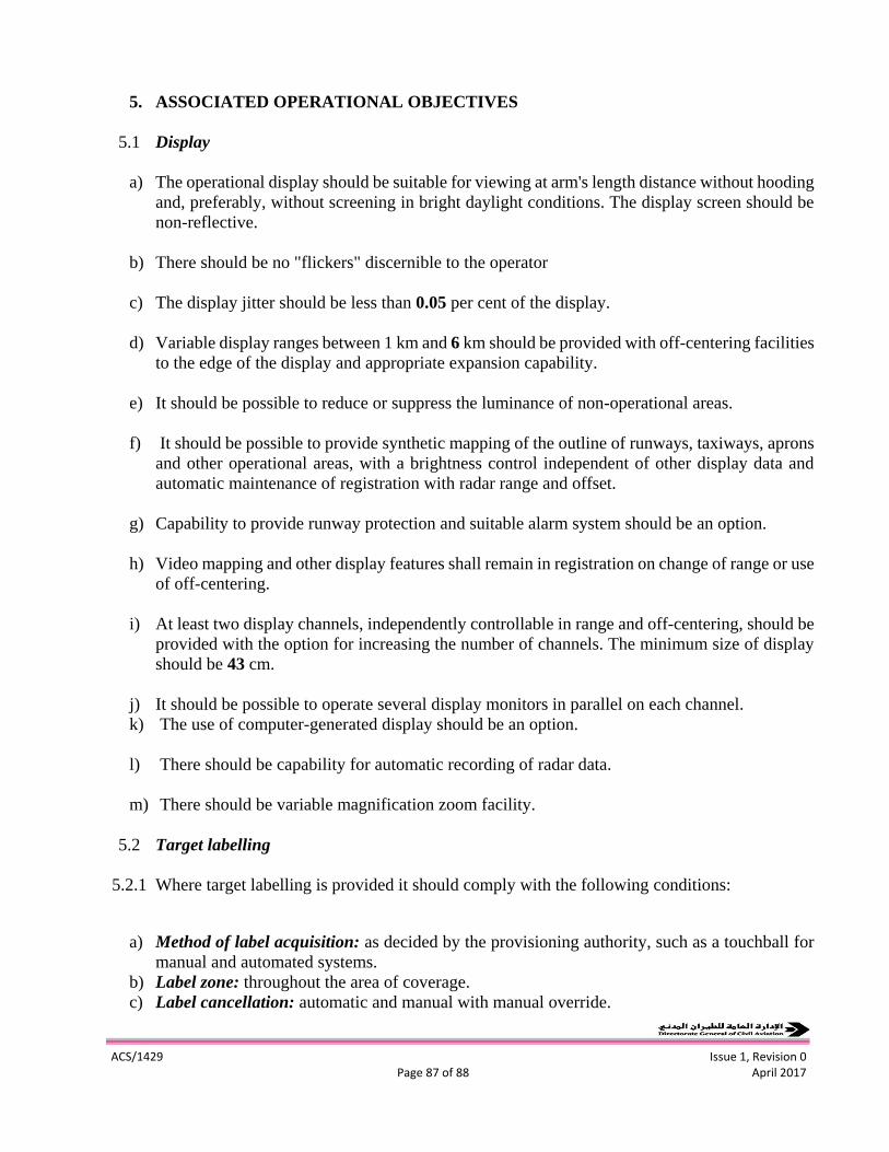
ACS/1429 Issue 1, Revision 0
Page 87 of 88 April 2017
5. ASSOCIATED OPERATIONAL OBJECTIVES
5.1 Display
a) The operational display should be suitable for viewing at arm's length distance without hooding
and, preferably, without screening in bright daylight conditions. The display screen should be
non-reflective.
b) There should be no "flickers" discernible to the operator
c) The display jitter should be less than 0.05 per cent of the display.
d) Variable display ranges between 1 km and 6 km should be provided with off-centering facilities
to the edge of the display and appropriate expansion capability.
e) It should be possible to reduce or suppress the luminance of non-operational areas.
f) It should be possible to provide synthetic mapping of the outline of runways, taxiways, aprons
and other operational areas, with a brightness control independent of other display data and
automatic maintenance of registration with radar range and offset.
g) Capability to provide runway protection and suitable alarm system should be an option.
h) Video mapping and other display features shall remain in registration on change of range or use
of off-centering.
i) At least two display channels, independently controllable in range and off-centering, should be
provided with the option for increasing the number of channels. The minimum size of display
should be 43 cm.
j) It should be possible to operate several display monitors in parallel on each channel.
k) The use of computer-generated display should be an option.
l) There should be capability for automatic recording of radar data.
m) There should be variable magnification zoom facility.
5.2 Target labelling
5.2.1 Where target labelling is provided it should comply with the following conditions:
a) Method of label acquisition: as decided by the provisioning authority, such as a touchball for
manual and automated systems.
b) Label zone: throughout the area of coverage.
c) Label cancellation: automatic and manual with manual override.
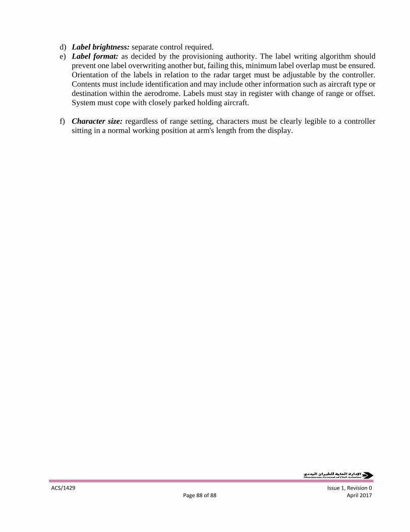
ACS/1429 Issue 1, Revision 0
Page 88 of 88 April 2017
d) Label brightness: separate control required.
e) Label format: as decided by the provisioning authority. The label writing algorithm should
prevent one label overwriting another but, failing this, minimum label overlap must be ensured.
Orientation of the labels in relation to the radar target must be adjustable by the controller.
Contents must include identification and may include other information such as aircraft type or
destination within the aerodrome. Labels must stay in register with change of range or offset.
System must cope with closely parked holding aircraft.
f) Character size: regardless of range setting, characters must be clearly legible to a controller
sitting in a normal working position at arm's length from the display.