state of california conservation and development
TRANSCRIPT

STATE OF CALIFORNIA State Energy Resources
Conservation and Development Commission
In the Matter of: ) DOCKET NUMBER: 09-AFC-3 ) Mariposa Energy Project ) CALPILOTS Testimony Traffic and ) Transportation - Aviation __________________________ )
Opening Testimony of California Pilots Association
The Byron Airport occupies approximately 1,307 acres at an airport reference elevation of 76 feet above Mean Sea Level (MSL). Figure 2-3 illustrates land uses within the Airport boundary and identifies key airfield facilities. The Airport has two nonintersecting runways each with a parallel taxiway and several connector taxiways. General aviation facilities are generally concentrated in “V” formed by the two runways with approximately 10 acres of aircraft storage area, 4 acres of apron, 125,000 square feet of hangars, and 2,400 square feet of office space. The majority of these facilities were constructed when the airport was built. Approximately 814 acres of Airport property to the south and west of the airfield are set aside as a wild life preserve. AIRFIELD FACILITIES Runways As shown on Figure 2-3, the airfield includes two runways. The primary runway, Runway 12-30 (northwest-southeast), is 4,500 feet long and 100 feet wide. The crosswind runway, Runway 5-23 is 3,000 feet long and 75 feet wide. Both runways have 20 feet unpaved shoulders. Table 2-1 summarizes runway data. Byron Airport was planned and designed in the 1980s and constructed in the early 1990s in accordance with FAA design standards. Byron’s airfield facilities meet FAA Airport Reference Code (ARC)* B-II** criteria and can accommodate aircraft with wingspans of up to (but not including) 79 feet and approach speeds of up to (but not including) 121knots
Imaginary Surfaces and Obstructions The airspace and land in the Airport environs consist of imaginary or obstacle limitation surfaces described below: Federal Aviation Regulations (FAR) Part 77. In order to determine whether an object is an obstruction to air navigation, several imaginary surfaces are established with relation to the Airport and to each runway. The size of the imaginary surfaces depends on the category of each runway and on the type of approach planned for
DATE JAN 07 2011
RECD. JAN 07 2011
DOCKET09-AFC-3

2
that runway (e.g., visual, nonprecision, etc.). The approach surface slope for each runway end at Byron is listed in Table 2-1 (Runway Data). According to Byron’s existing ALP and FAA information dated October 30, 2003, no obstructions to FAR Part 77 surfaces have been found. Even though they do not penetrate the 20:1 approach surface, some of the power generated wind mills to the west and southwest are equipped with obstruction lights. Runway Protection Zones. A runway protection zone (RPZ) is a trapezoidal area centered about the extended runway centerline that enhances protection of people and property on the ground. RPZ dimensions vary with the type of aircraft and approach visibility minimums associated with that runway end. As shown on Figure 2-3, all land underlying the existing RPZs, is within the Airport boundary, except for very small triangle of pasture land beneath the approach to Runway 5 and a second small triangle beneath the approach to Runway 12. Portions of Armstrong Road and Falcon Way are in the RPZ area of Runway 12. Safety and Approach-Departure Zones. The Byron Airport Land Use Compatibility Plan (ALUCP) designates safety zones to restrict incompatible land uses around the Airport. Safety zones have the same dimensions as RPZs. Approach and departure zones begin at the outer end of the safety zones, and
extend outward to a distance determined by the intersection between the approach surface and a horizontal surface located 150 feet above the established airport elevation. Existing land uses in the Airport environs are compatible with existing safety and approach-departure zones. Obstructions. Obstruction data for each runway approach are shown on the Byron Airport Layout Plan Air Traffic Control The Airport is a non-towered airport lying within Class E airspace, which extends for a 5-mile radius around the Airport and from 700 feet above ground level up to 18,000 feet above mean sea level (MSL). Air traffic is controlled by the use of CTAF/UNICOM at a frequency of 123.05 MHz and an AWOS-3 system at a frequency of 123.775 MHz. Air traffic control (ATC) exercises no control over flights and no separation services are provided to aircraft operating under Visual Flight Rules (VFR) in Class E airspace. Radio communication and transponders are not required for VFR operation, however IFR flights must be capable of communicating with ATC, and must be equipped with a Mode C transponder. The Northern California Terminal Radar Approach Control (TRACON) provides radar approach and departure control and other air traffic control services at the Airport. The Airport lies outside the controlled airspace of Oakland and San Francisco international airports. Navigation Aids Navigational aids associated with each runway are listed in Table 2-1 and summarized below. • Non-Precision Approach. Runway 30 has a GPS designated approach.

3
• Precision Approach Path Indicator. A precision approach path indicator (PAPI) is a visual slope indicator that provides, through a system of lights, the proper approach slope to a runway, similar to the glide slope of an instrument landing system (ILS). PAPI systems are intended for day and night use under visual flight conditions. Runways 30 and 23 are equipped with two-light PAPI on left (3.5 degrees glide path). Runways 5 and 12 currently do not have approach lighting systems.
• Runway Lighting. Runways 5, 12, 23 and 30 are equipped with medium intensity runway lighting (MIRL) and Runway 30 is also equipped with runway end identifier lights (REIL). All runway lighting is by pilot controlled by activating the local Airport radio frequency.
FAA As set forth in Title 49 of the U.S. Code of Federal Regulations, §40103, “The United States Government has exclusive sovereignty of airspace of the United States.” In protecting and administering the use of U.S. airspace, The Administrator [of the FAA] shall prescribe air traffic regulations on the flight of aircraft (including regulations on safe altitudes) for— (A) navigating, protecting, and identifying aircraft; (B) protecting individuals and property on the ground; (C) using the navigable airspace efficiently; and (D) preventing collision between aircraft, between aircraft and land or water vehicles, and between aircraft and airborne objects.1
Power Plant Locations: The East Altamont power plant is located approximately 0.5 miles east of from the center line of runway 30 and well inside the primary boundary of the RNAV IAPA 8260.54A while MEP is located approximately 167 feet from the secondary boundary of the RNAV IAPA 8260.54A. Refer to Attached CALPILOTS Byron Airport C83 RNAV with Notes, FAA Part 77 Case study East Altamont, and FAA Part 77 Case Study MEP. Plume Hazard and FAA Study (AIM)
Plume Hazard Occasionally, construction proponents assume, incorrectly, that there are no aeronautical height limitations beyond the edges of the FAR Part 77 civil airport imaginary surfaces. However, TERPS surfaces and other aeronautical factors can be lower than, and/or extend beyond, the FAR Part 77 civil airport imaginary surfaces. IBID
Page 16
FAA AIM FAA AIM Plume is a Hazard, see attached CALPILOTS FAA Plume Pages from AIM chg 18-26-10 1 ACRP Report 38, Understanding Airspace, Objects and their Effects on Airports, Airport Cooperative research
Program,Transportation Research Board, Sponsored by the Federal Aviation Administration., p26
http://www.trb.org/ACRP/Blurbs/Understanding_Airspace_Objects_and_Their_Effects_o_164477.aspx

4
Also, the FAA reserves the right to rescind the DNH at any time if new aeronautical information comes to light that was not known to the FAA at the time they performed the analysis that led to the DNH; however, such rescissions of determinations are rare. IBID,
page 40, No. 3
SSA However, the site is not within or immediately adjacent to any published approach/departure patterns or the traffic pattern for the airport. Even allowing for drift and expansion of the potentially affected area due to merged plumes, the area of potential hazard would not encroach on any established approach/departure or traffic pattern. In addition, the number of aircraft traversing the site is relatively low, even when compared to traffic in the surrounding area. The airspace above and immediately surrounding the project site is not an established student pilot training area or designated jump site, and does not show extensive use by ultralights or gliders. The elevation of the terrain east of the project site rises sharply and there are transmission lines and other structures that discourage low altitude flight in the project vicinity. There are also no noise or other restrictions that would force pilots to overfly the project site in order to execute approach or departure procedures, or enter the pattern.
Conclusion: Two power plants in or close to the RNAV protected zone to Runway 30 would cause a safety hazard to all aircraft and would be distraction to pilots using the RNAV approach and the VFR approach to runway 30. The distance between the power plants would make it impossible to mitigate to have a effective and safe approach to runway 30. In addition by extending runway 30 closer to the location of the power plants would reduce the altitude aircraft would fly over and near the both MEP and East Altamont.

5
DECLARATION OF Andy Wilson, Private Pilot with Instrument Rating
California Pilots Association Director-at-Large Aircraft Owners and Pilots Association (Member since 1980)
I Andy Wilson declare as follows:
1) I prepared the Opening Traffic and Transportation – Aviation Testimony of CALPILOTS on the MEP.
2) It is my professional opinion that the prepared testimony is valid and
accurate with respect to the issues addressed therein. 3) I am personally familiar with the facts and conclusions related in the
testimony and if called as a witness could testify competently thereto.
4) A copy of my professional qualifications is forthcoming. I declare under penalty of perjury, under the laws of the State of California, that the forgoing is true and correct to the best of my knowledge and belief, and that this declaration was executed on January 7, 2011 in Hayward, California.
____________________________
Signed 2-7-11

6
DECLARATION OF SERVICE
I, Andy Wilson, declare that on January 7, 2011, I served and filed copies of the attached CALPILOTS First Testimony. The original documents, filed with the Docket Unit, is accompanied by a copy of the most recent Proof of Service list, located on the web page for this project at:
[http://www.energy.ca.gov/sitingcases/mariposa/index.html]. The document has been sent to both the other parties in this proceeding (as shown on the Proof of Service list) and to the Commission’s Docket Unit, in the following manner: (Check all that Apply)
FOR SERVICE TO ALL OTHER PARTIES:
__X____ sent electronically to all email addresses on the Proof of Service list;
______ by personal delivery;
______ by delivering on this date, for mailing with the United States Postal Service with first-class postage thereon fully prepaid, to the name and address of the person served, for mailing that same day in the ordinary course of business; that the envelope was sealed and placed for collection and mailing on that date to those addresses NOT marked “email preferred.”
AND
FOR FILING WITH THE ENERGY COMMISSION:
sending an original paper copy and one electronic copy, mailed and emailed respectively, to the address below (preferred method);
CALIFORNIA ENERGY COMMISSION Attn: Docket No. 09-AFC-3 1516 Ninth Street, MS-4 Sacramento, CA 95814-5512
[email protected] I declare under penalty of perjury that the foregoing is true and correct, that I am employed in the county where this mailing occurred, and that I am over the age of 18 years and not a party to the proceeding.
___________________________ Signed 1-7-11

7
[email protected] [email protected] [email protected] [email protected] [email protected] [email protected] [email protected] [email protected] [email protected] [email protected] [email protected]
[email protected] [email protected] [email protected] [email protected] [email protected]
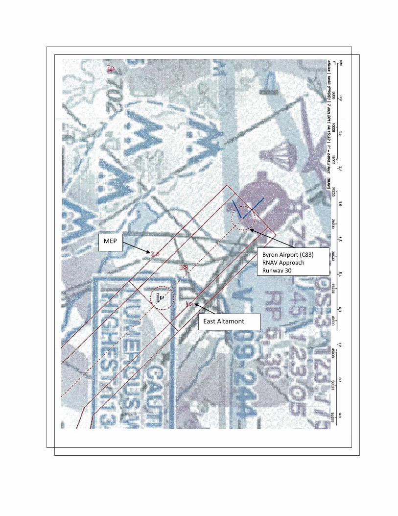
MEP
East Altamont
Byron Airport (C83) RNAV Approach Runway 30
East Altamont
MEP

AIM2/11/10
7−5−13Potential Flight Hazards
6. Always consider canceling or delaying aflight if weather conditions do not support a safeoperation.
c. If you haven’t already developed a set ofStandard Operating Procedures for cold weatheroperations, they should include:
1. Procedures based on information that isapplicable to the aircraft operated, such as AFMlimitations and procedures;
2. Concise and easy to understand guidance thatoutlines best operational practices;
3. A systematic procedure for recognizing,evaluating and addressing the associated icing risk,and offer clear guidance to mitigate this risk;
4. An aid (such as a checklist or reference cards)that is readily available during normal day−to−dayaircraft operations.
d. There are several sources for guidance relatingto airframe icing, including:
1. http://aircrafticing.grc.nasa.gov/index.html
2. http://www.ibac.org/is−bao/isbao.htm
3. http://www.natasafety1st.org/bus_deice.htm
4. Advisory Circular (AC) 91−74, Pilot Guide,Flight in Icing Conditions.
5. AC 135−17, Pilot Guide Small AircraftGround Deicing.
6. AC 135−9, FAR Part 135 Icing Limitations.
7. AC 120−60, Ground Deicing and Anti−icingProgram.
8. AC 135−16, Ground Deicing and Anti−icingTraining and Checking.
The FAA Approved Deicing Program Updates ispublished annually as a Flight Standards InformationBulletin for Air Transportation and contains detailedinformation on deicing and anti−icing procedures andholdover times. It may be accessed at the followingweb site by selecting the current year’s informationbulletins:http://www.faa.gov/library/manuals/examiners_inspectors/8400/fsat
7−5−15. Avoid Flight in the Vicinity ofThermal Plumes (Smoke Stacks andCooling Towers)
a. Flight Hazards Exist Around ThermalPlumes. Thermal plumes are defined as visible orinvisible emissions from power plants, industrialproduction facilities, or other industrial systems thatrelease large amounts of vertically directed unstablegases. High temperature exhaust plumes may causesignificant air disturbances such as turbulence andvertical shear. Other identified potential hazardsinclude, but are not necessarily limited to, reducedvisibility, oxygen depletion, engine particulatecontamination, exposure to gaseous oxides, and/oricing. Results of encountering a plume may includeairframe damage, aircraft upset, and/or enginedamage/failure. These hazards are most criticalduring low altitude flight, especially during takeoffand landing.
b. When able, a pilot should fly upwind ofpossible thermal plumes. When a plume is visiblevia smoke or a condensation cloud, remain clear andrealize a plume may have both visible and invisiblecharacteristics. Exhaust stacks without visibleplumes may still be in full operation, and airspace inthe vicinity should be treated with caution. As withmountain wave turbulence or clear air turbulence, aninvisible plume may be encountered unexpectedly.Cooling towers, power plant stacks, exhaust fans, andother ismilar structures are depicted in FIG 7−5−2.Whether plumes are visible or invisible, the totalextent of their unstable air is difficult to ascertain.FAA studies are underway to further characterize theeffects of thermal plumes as exhaust effluents. Untilthe results of these studies are known and possiblechanges to rules and policy are identified and/orpublished, pilots are encouraged to exercise cautionwhen flying in the vicinity of thermal plumes. Pilotsare encouraged to reference the Airport/FacilityDirectory where amplifying notes may caution pilotsand identify the location of structure(s) emittingthermal plumes.
8/26/10 AIM

AIM 2/11/10
7−5−14 Potential Flight Hazards
FIG 7−5−2
Plumes
3/15/077110.65R CHG 2AIM 8/26/10

Overview
Study (ASN): 2001-AWP-2169-OE
Prior Study:
Status: Determined
Letters:
Supplemental Form 7460-2:
Please login to add a Supplemental Form 7460-2.
Received Date: 06/08/2001
Entered Date: 06/11/2001
Completion Date: 06/28/2001
Expiration Date: 12/28/2002
Sponsor Information
Sponsor's Representative
Information
Sponsor: EAST ALTAMOUNT ENERGY CENTER
Attention Of: STEVE DEYOUNG
Address: 6700 KOLL CENTER PARKWAY, STE 200
Address2:
City: PLEASANTON
State: CA
Postal Code: 94566
Country: US
Phone: 925 600-2304
Fax:
Representative:
Attention Of:
Address:
Address2:
City:
State:
Postal Code:
Country:
Phone:
Fax:
Construction Info
Structure Summary
Notice Of:
Duration: (Months: 0 Days: 0)
Work Schedule:
Date Built:
Structure Type: Other w/o Antenna
Structure Name:
ORS Number:
FCC Number:
Structure Details
Height and Elevation
Latitude (NAD 83): 37° 48' 14.22" N
Longitude (NAD 83): 121° 34' 27.88" W
Horizontal Datum: NAD 83
Survey Accuracy: 4D
Marking/Lighting: None
Other Description:
Name:
City: TRACY
State: CA
Nearest Airport: BYRON AIRPORT
Distance to Structure:
On Airport: No
Direction to Structure:
Description of Location:
Description of Proposal: "EAST ALTAMONT ENERGY CENTER" POWERPLANT FACILITYSOUTHEAST OF BYRON BETHANY & MOUNTAIN HOUSE ROADS
Proposed
DNE
DET
Site Elevation: 34
Structure Height: 175 0 175
Total Height (AMSL):
209 34 209
Frequencies Low Freq High Freq Unit ERP Unit

Overview
Study (ASN): 2009-AWP-2565-OE
Prior Study:
Status: Determined
Letters: Determination
Supplemental Form 7460-2:
Please login to add a Supplemental Form 7460-2.
Received Date: 05/29/2009
Entered Date: 05/29/2009
Completion Date: 07/29/2009
Expiration Date: 01/29/2011
Map: View Map
Sponsor Information
Sponsor's Representative Information
Sponsor: Mariposa Energy, LLC.
Attention Of: Bo Buchynsky
Address: 333 South Grand Avenue
Address2: Suite 1570
City: Los Angeles
State: CA
Postal Code: 90071
Country: US
Phone: (213) 473-0092
Fax: (213) 620-1170
Representative:
CH2M HILL
Attention Of: Megan Sebra
Address: 2485 Natomas Park Dr. Ste. 600
Address2:
City: Sacramento
State: CA
Postal Code: 95833
Country: US
Phone: 916-286-0276
Fax: 916-614-3418
Construction Info
Structure Summary
Notice Of: CONSTR
Duration: PERM (Months: 0 Days: 0)
Work Schedule: 09/01/2010 to 09/01/2011
Date Built:
Structure Type: Stack
Structure Name:
Power Plant Exhaust Stack 1
ORS Number:
FCC Number:
Structure Details
Height and Elevation
Latitude (NAD 83): 37° 47' 16.81" N
Longitude (NAD 83): 121° 36' 06.43" W
Horizontal Datum: NAD 83
Survey Accuracy: 4D
Marking/Lighting: None
Other Description:
Name:
City: Byron
State: CA
Nearest Airport: C83
Distance to Structure: 16283.36 feet
On Airport: No
Direction to Structure: 154.83°
Description of Location: The MEP is approximately 10-acres of a 158-

acre parcel south of the PG&E Bethany Compressor Station and Kelso 230 kV Substation. The facility will be located SE of the intersection of Bruns Rd & Kelso Rd in unincorporated Alameda County, CA. The site parcel is located in APN Nos. 099B-7050-001-10.
Description of Proposal: The MEP will be a nominal 200-MW peaking facility consisting of 4 GE Energy LM6000 PC Sprint natural gas-fired combustion turbine generators & associated equipment. The tops of the exhaust stacks & power poles will be less than 100 feet agl.

Overview
Study (ASN): 2009-AWP-2566-OE
Prior Study:
Status: Determined
Letters: Determination
Supplemental Form 7460-2:
Please login to add a Supplemental Form 7460-2.
Received Date: 05/29/2009
Entered Date: 05/29/2009
Completion Date: 07/29/2009
Expiration Date: 01/29/2011
Map: View Map
Sponsor Information
Sponsor's Representative Information
Sponsor: Mariposa Energy, LLC.
Attention Of: Bo Buchynsky
Address: 333 South Grand Avenue
Address2: Suite 1570
City: Los Angeles
State: CA
Postal Code: 90071
Country: US
Phone: (213) 473-0092
Fax: (213) 620-1170
Representative:
CH2M HILL
Attention Of: Megan Sebra
Address: 2485 Natomas Park Dr. Ste. 600
Address2:
City: Sacramento
State: CA
Postal Code: 95833
Country: US
Phone: 916-286-0276
Fax: 916-614-3418
Construction Info
Structure Summary
Notice Of: CONSTR
Duration: PERM (Months: 0 Days: 0)
Work Schedule: 09/01/2010 to 09/01/2011
Date Built:
Structure Type: Stack
Structure Name:
Power Plant Exhaust Stack 2
ORS Number:
FCC Number:
Structure Details
Height and Elevation
Latitude (NAD 83): 37° 47' 18.26" N
Longitude (NAD 83): 121° 36' 05.79" W
Horizontal Datum: NAD 83
Survey Accuracy: 4D
Marking/Lighting: None
Other Description:
Name:
City: Byron
State: CA
Nearest Airport: C83
Distance to Structure: 16172.99 feet
On Airport: No
Direction to Structure: 154.44°
Description of Location: The MEP is approximately 10-acres of a 158-
Proposed
DNE
DET
Site Elevation: 126
Structure Height: 80 0 80
Total Height (AMSL):
206 0 206
Frequencies Low Freq High Freq Unit ERP Unit

acre parcel south of the PG&E Bethany Compressor Station and Kelso 230 kV Substation. The facility will be located SE of the intersection of Bruns Rd & Kelso Rd in unincorporated Alameda County, CA. The site parcel is located in APN Nos. 099B-7050-001-10.
Description of Proposal: The MEP will be a nominal 200-MW peaking facility consisting of 4 GE Energy LM6000 PC Sprint natural gas-fired combustion turbine generators & associated equipment. The tops of the exhaust stacks & power poles will be less than 100 feet agl.
Overview
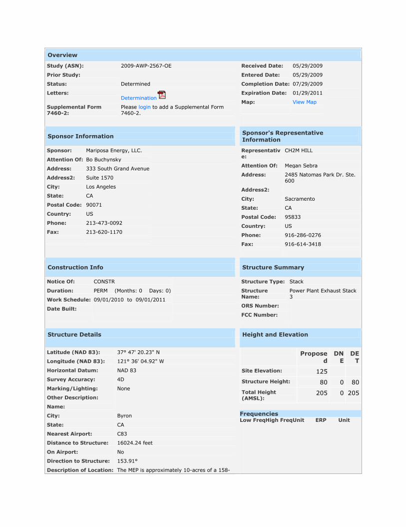
Study (ASN): 2009-AWP-2567-OE
Prior Study:
Status: Determined
Letters: Determination
Supplemental Form 7460-2:
Please login to add a Supplemental Form 7460-2.
Received Date: 05/29/2009
Entered Date: 05/29/2009
Completion Date: 07/29/2009
Expiration Date: 01/29/2011
Map: View Map
Sponsor Information
Sponsor's Representative Information
Sponsor: Mariposa Energy, LLC.
Attention Of: Bo Buchynsky
Address: 333 South Grand Avenue
Address2: Suite 1570
City: Los Angeles
State: CA
Postal Code: 90071
Country: US
Phone: 213-473-0092
Fax: 213-620-1170
Representative:
CH2M HILL
Attention Of: Megan Sebra
Address: 2485 Natomas Park Dr. Ste. 600
Address2:
City: Sacramento
State: CA
Postal Code: 95833
Country: US
Phone: 916-286-0276
Fax: 916-614-3418
Construction Info
Structure Summary
Notice Of: CONSTR
Duration: PERM (Months: 0 Days: 0)
Work Schedule: 09/01/2010 to 09/01/2011
Date Built:
Structure Type: Stack
Structure Name:
Power Plant Exhaust Stack 3
ORS Number:
FCC Number:
Structure Details
Height and Elevation
Latitude (NAD 83): 37° 47' 20.23" N
Longitude (NAD 83): 121° 36' 04.92" W
Horizontal Datum: NAD 83
Survey Accuracy: 4D
Marking/Lighting: None
Other Description:
Name:
City: Byron
State: CA
Nearest Airport: C83
Distance to Structure: 16024.24 feet
On Airport: No
Direction to Structure: 153.91°
Description of Location: The MEP is approximately 10-acres of a 158-
Proposed
DNE
DET
Site Elevation: 125
Structure Height: 80 0 80
Total Height (AMSL):
205 0 205
Frequencies Low Freq High Freq Unit ERP Unit

acre parcel south of the PG&E Bethany Compressor Station and Kelso 230 kV Substation. The facility will be located SE of the intersection of Bruns Rd & Kelso Rd in unincorporated Alameda County, CA. The site parcel is located in APN Nos. 099B-7050-001-10.
Description of Proposal: The MEP will be a nominal 200-MW peaking facility consisting of 4 GE Energy LM6000 PC Sprint natural gas-fired combustion turbine generators & associated equipment. The tops of the exhaust stacks & power poles will be less than 100 feet agl.

Overview
Study (ASN): 2009-AWP-2568-OE
Prior Study:
Status: Determined
Letters: Determination
Supplemental Form 7460-2:
Please login to add a Supplemental Form 7460-2.
Received Date: 05/29/2009
Entered Date: 05/29/2009
Completion Date: 07/29/2009
Expiration Date: 01/29/2011
Map: View Map
Sponsor Information
Sponsor's Representative Information
Sponsor: Mariposa Energy, LLC.
Attention Of: Bo Buchynsky
Address: 333 South Grand Avenue
Address2: Suite 1570
City: Los Angeles
State: CA
Postal Code: 90071
Country: US
Phone: 213-473-0092
Fax: 213-620-1170
Representative:
CH2M HILL
Attention Of: Megan Sebra
Address: 2485 Natomas Park Dr. Ste. 600
Address2:
City: Sacramento
State: CA
Postal Code: 95833
Country: US
Phone: 916-286-0276
Fax: 916-614-3418
Construction Info
Structure Summary
Notice Of: CONSTR
Duration: PERM (Months: 0 Days: 0)
Work Schedule: 09/01/2010 to 09/01/2011
Date Built:
Structure Type: Stack
Structure Name:
Power Plant Exhaust Stack 4
ORS Number:
FCC Number:
Structure Details
Height and Elevation
Latitude (NAD 83): 37° 47' 21.66" N
Longitude (NAD 83): 121° 36' 04.28" W
Horizontal Datum: NAD 83
Survey Accuracy: 4D
Marking/Lighting: None
Other Description:
Name:
City: Byron
State: CA
Nearest Airport: C83
Distance to Structure: 15917.45 feet
On Airport: No
Direction to Structure: 153.52°
Description of Location: The MEP is approximately 10-acres of a 158-
Proposed
DNE
DET
Site Elevation: 125
Structure Height: 80 0 80
Total Height (AMSL):
205 0 205
Frequencies Low Freq High Freq Unit ERP Unit

acre parcel south of the PG&E Bethany Compressor Station and Kelso 230 kV Substation. The facility will be located SE of the intersection of Bruns Rd & Kelso Rd in unincorporated Alameda County, CA. The site parcel is located in APN Nos. 099B-7050-001-10.
Description of Proposal: The MEP will be a nominal 200-MW peaking facility consisting of 4 GE Energy LM6000 PC Sprint natural gas-fired combustion turbine generators & associated equipment. The tops of the exhaust stacks & power poles will be less than 100 feet agl.
