start inertia loads
TRANSCRIPT

8/3/2019 Start Inertia Loads
http://slidepdf.com/reader/full/start-inertia-loads 1/8
IEEE TRANSACTIONS ON INDUSTRY APPLICATIONS, VOL. 37, NO. 1, JANUARY/FEBRUARY 2001 137
Starting High-Inertia LoadsRobbie F. McElveen , Member, IEEE, and Michael K. Toney , Senior Member, IEEE
Abstract—Common methods used to start ac induction motors
driving high-inertia loads include across-the-line starting andreduced-voltage starting by autotransformer, wye–delta, orresistor/reactor. Application of these methods is generally welldocumented and understood. However, with the increased use of electronic soft starters and variable-frequency drives, applicationscan be markedly different. This paper reviews the aforementionedmethods and explains the benefits and limitations of each. Theeffect of high-inertia loads on both acceleration time and motorheating is examined. A case history of starting a centrifuge withan electronic soft starter is studied. Finally, a comparison of all of the methods is presented with recommendations on choosing theproper starter given.
Index Terms—Inertia, motors, soft start, starting, variable-fre-quency drives.
I. INTRODUCTION
MANY METHODS are used to reduce the current draw
during startup of high-inertia applications such as cen-
trifuges, hammermills, or large fans. Reduced current condi-
tions are desired not only to lessen the burden on the elec-
trical system and avoid power company penalties, but also to
decrease the strain on both the motor and the connected mechan-
ical system. This reduction in starting current, however, leads to
a corresponding reduction in the starting torque available from
the motor. For the purposes of this paper, starting torque is con-
sidered to be the average torque produced by the motor which is
available to accelerate the load. This reduction in torque leads to
longer acceleration times and the potential for increased heating
during startup. The goal of this paper is to evaluate the “con-
ventional” methods of starting, to explain how soft starters and
variable-frequency drive (VFD) starting works, and to compare
each of the methods for temperature rise, acceleration time, and
economical considerations.
First, a brief overview of starting methods (including soft start
and VFD starting) is presented. Next, the effects of inertia on
both acceleration time and motor heating are discussed. Com-
parisons for starting time, temperature rise, and other factors
are made. An actual case history of a soft-started centrifuge
is presented, including the problems and solutions associated
with this application. Following this case history, the calculation
Paper PID 98–06, presented at the 1997 IEEE Petroleum and Chemical In-dustry Technical Conference, Banff, AB, Canada, September 15–17, and ap-proved for publication in the IEEE TRANSACTIONS ON INDUSTRY APPLICATIONS
by the Petroleum and Chemical Industry Committee of the IEEE Industry Ap-plications Society. Manuscript submitted for review September 17, 1997 andreleased for publication October 15, 1999.
R. McElveen was with Reliance Electric-Rockwell Automation, KingsMountain, NC 28086 USA. He is now with John Deere, Charlotte, NC 28241USA (e-mail: [email protected]).
M. Toney is with Amoco Corporation, Houston, TX 77058 USA (e-mail:[email protected]).
Publisher Item Identifier S 0093-9994(01)00280-8.
methods used for both soft start and VFD starting are explained.
A special emphasis is placed on the motor losses and heating foreach of these starting methods. Finally, factors which should be
considered when choosing a starter are discussed and recom-
mendations given.
II. METHODS OF STARTING INDUCTION MOTORS
Methods of starting ac induction motors can be broken
down into four basic categories: Full-voltage (across-the-line)
starting, electromechanical reduced-voltage starting, solid-state
reduced-voltage starting, and VFD starting. Electromechanical
reduced-voltage starting has been in existence nearly as long as
the induction motor itself. This starting method encompasses
autotransformer starting, wye–delta (star–delta) starting, andresistor/reactor starting. Each of these methods requires the use
of some type of mechanical switch or contact. Electromechan-
ical starting is the most common method of reduced voltage
starting used in industry today.
Solid-state starters, on the other hand, have only been in
existence since the early 1970s. This method of starting uses
programmable logic controllers in combination with sophis-
ticated power electronic circuits to provide reduced voltage
and/or torque. Advances made in the electronics industry with
new high-power diodes and SCRs have led to the development
of both electronic soft starters as well as inverter controlled
VFDs. In each of these cases, smooth, electronically controlled
starts can be achieved with a high degree of process control.
A. Full-Voltage (Across-the-Line) Starting
Of the many methods used to start induction motors, full-
voltage (or across-the-line) starting is typically used unless
there is either an electrical or mechanical constraint which
makes this option unsuitable. With this method, full voltage
is applied to the motor at the instant the “switch” is thrown.
This method of starting results in a large initial current surge,
known as inrush, which is typically 600% to 700% rms of
the full-load current drawn by the motor. In reality, the first
half-cycle current is considerably higher in magnitude, but is
short in duration. This large inrush can cause problems for
the connected electrical system. Power companies may applyrestrictions as to how much current draw is allowed. These
restrictions are typically specified as the maximum allowable
voltage drop at the incoming power connection point or the
maximum allowable kilovoltamperes that may be drawn by
the plant. These restrictions may limit when and how many
times a particular motor can be started. By limiting the in-
rush, the corresponding voltage drop will be reduced. An-
other problem can be with in-plant bus capacity where the
given system simply cannot handle this large current draw.
Brownout or other associated problems may be experienced
0093–9994/01$10.00 © 2001 IEEE

8/3/2019 Start Inertia Loads
http://slidepdf.com/reader/full/start-inertia-loads 2/8
138 IEEE TRANSACTIONS ON INDUSTRY APPLICATIONS, VOL. 37, NO. 1, JANUARY/FEBRUARY 2001
if the voltage dips too much. Furthermore, this inrush current
induces large magnetic forces in the stator windings, which
actually try to force the windings to move and distort. This
transitory force can eventually lead to deterioration of the
insulation between the windings, especially if adequate coil
head bracing techniques are not employed.
Full-voltage starting produces the greatest amount of starting
torque. High starting torque is generally desired when trying tostart a high-inertia load in order to limit the acceleration time.
However, in certain cases, this high starting torque may damage
the mechanical system. Gears or chainsmight be broken or dam-
aged. Strain or slippage may reduce belt life. Gearboxes are also
put under a greater stress and are subject to more abuse. Voltage
drop on the system must be carefully studied and the breaker/re-
lays need to be coordinated with upstream devices to prevent
nuisance tripping of these devices during startup. If the voltage
drop limitation for the system is exceeded, other methods of
starting should be considered. Beyond the initial shock of in-
rush current and torque, this type of starting does result in a
smooth acceleration characteristic with the shortest acceleration
time, which offers an advantage over some of the other availablemethods of starting.
B. Electromechanical Reduced-Voltage Starting
Another popular method of starting which is used to limit
inrush current is reduced-voltage starting. With any type of
reduced-voltage starting, the theoretical current drawn by
the motor decreases linearly with decreasing voltage. (The
exception is VFD starting where the frequency changes as
well as the voltage. This is a special topic and is discussed
more thoroughly in a later section.) Similarly, the torque is
theoretically reduced by the square of the percent voltage ratio,
(i.e., 80% reduced voltage results in (0.8) = 0.64 or 64% of nominal motor torque). Although the motor torque and current
are dependent upon many factors such as saturation, deep bar
effect, and skin effect, a good approximation of the current
and torque at any speed and reduced voltage condition may be
found by using the following equations:
(1)
(2)
where
current at reduced voltage;
rated current;
reduced voltage;
rated voltage;
reduced torque;
rated torque.
Note that the proportion constants used as exponents in the
above equations are factors developed from locked-rotor satu-
ration testing and areapplicable to the majority of induction mo-
tors.
Electromechanical reduced-voltage starting can be achieved
in the folowing three ways:
1) autotransformer;
2) wye–delta;
3) primary resistor/reactor.
With autotransformer starting, a tapped transformer is used
to supply reduced voltage to the motor. Typically, as the motor
gains speed, the taps are changed to increase the voltage to the
motor terminals. However, this switching of voltage can result
in a high spike of current during this transitory period of opera-
tion. The magnitude of this spike is dependent upon the motor
speed and current when the switching occurs. There is a torque
transient associated withthis current peakwhich again maycauseproblems for the driven equipment. Note that this phenomenon
is notpresent if closedtransitionstartingis used where thecircuit
is neveractuallyopened during the switching operation. One big
advantagefromthe powersystemstandpointisthatthe linecurrent
on the distribution side of the autotransformer is reduced by the
squareof thevoltage ratioat thepowersystem input.Forthe other
methodsmentionedinthissection,thelinecurrentvariesdirectly.
However, autotransformer starting is a more costly method than
eitherwye–deltaorresistor/reactorstarting.
The second type of electromechanical reduced-voltage
starting that is used extensively is wye-start, delta-run. This is
particularly true for motor voltages of less than 1000 V. With
this type of starting method, a normally delta-connected statoris connected in wye during the initial startup phase. It is most
common for the motor to reach full speed before the transition
to the delta connection is made. However, it is possible for
the connection to be switched from wye to delta as the motor
approaches 50%–60% of full-load speed. This essentially
applies full voltage to the motor at this point. The advantage
of connecting the stator in wye is that only times rated
voltage is applied to the phase windings. This results in only
1/3 of nominal current draw, but reduces the starting torque
by a factor of three as well. When the stator connection is
switched from wye to delta, a transitory current arises which
can often be equal to or greater than the peak current seen with
across-the-line starting. Again, this current and resulting torque
transient is present only if open transition is used and is not a
problem for closed transition switching. A drawback of this
method is that it requires the neutrals of the motor, in addition
to the normal line leads, to be externally connected (six leads).
Thus, this starter is not an option for use with a motor that was
originally constructed with only three leads.
Fig. 1(a) and (b) illustrates the relative magnitudes of torque
and current for both wye and delta configurations. Both NEMA
Design B-type and Design C-type motor curves are shown for
comparative purposes. Note the very low amount of torque
available on the wye connection for the Design B characteristic.
This low amount of available starting torque is an importantissue to keep in mind when this type of starting method is being
considered.
Wye-delta starting requires additional contactors in the
starter, which drives up the cost of the equipment. Two cable
runs to the field have to be installed in order to perform
wye-delta switching and starters must be interlocked in order
to prevent catastrophic failure. Again, there is additional heat
generated that must be taken into account at the starter, the
lead cable, and at the motor. This system is relatively simple
to operate, but adjusting the starting characteristics is not an
option once the system is installed. Overload protection needs
to be designed for both the wye and delta connections.

8/3/2019 Start Inertia Loads
http://slidepdf.com/reader/full/start-inertia-loads 3/8
MCELVEEN AND TONEY: STARTING HIGH-INERTIA LOADS 139
(a)
(b)
Fig. 1. (a) Comparison of torque and amperes for wye and delta connections(NEMA Design B). (b) Comparison of torque and amperes for wye and deltaconnections (NEMA Design C).
Primary resistor/reactor starting is achieved by placing a re-
sistance or inductance in series with the motor leads in order to
reduce the inrush current. The torque is again reduced by the
voltage ratio as shown in (2), while the line current decreases
per (1). Again, when the motor is nearly up to speed, the resistor
or reactor may be switched out of the circuit, causing transitory
currents with their corresponding torque pulsations. Energy is
wasted as heat is dissipated in the resistor during each startup
cycle. Less energy is wasted when using a reactor, but the mag-
nitude can still be significant.
C. Electronic Soft Starting
There are two basic categories of soft-starting methods: cur-
rent-limit starting and voltage-ramp starting. Most of today’s
units offer both options (or various combinations) in one starter
package so that the starting characteristic can be optimized to
provide a more healthy start for both the motor and connected
equipment.
Voltage ramp starting is the simplest form of soft starting
in which a microprocessor is used to control the firing angle
of pairs of SCRs, thus progressively increasing the voltage
supplied to the motor. In order to understand the effect the firing
(a)
(b)
Fig. 2. Waveshapes for 0 and 90 firing angles.
Fig. 3. Voltage waveshape for inductive load (90 firing angle).
angle of the SCRs has on the voltage waveshape and harmonic
content, consider the following example for a single phase
voltage source. Fig. 2 shows the percentage 1st (fundamental),
3rd, 5th, and 7th harmonics for a phased back sine wave. If
the phased back angle were 90 , the percent content of each
harmonic would be as shown in Fig. 2(a) (% fundamental100) and Fig. 2(b) (% fundamental 58.5; % 3rd 31.7; %
5th 10.7; % 7th 10.5).
Please note that this analysis is only applicable for a resistive
load. Due to the fact that the current lags the voltage for an
inductive load (such as a motor), the voltage waveshape will
be somewhat different. In order to turn off an SCR, the current
through the SCR must pass through zero. The resultant voltage
waveshape will resemble that shown in Fig. 3
Harmonics produce pulsating torques whose net total is zero.
These harmonics contribute to additional losses (heating) in the
motor. Useable motor torque is produced only by the funda-
mental component of the voltage. The usable fundamental com-
ponent of the voltage can be considerably less than the rmsvalue, depending upon the complexity of the circuit used to
fire the SCRs. This factor must be considered when designing a
motor for use with this type of starter.
With voltage ramp starting, it is possible for the user to set the
initial voltage which will be applied at time zero and to specify
the ramp time (how long it will take the voltage to rise from its
initial to final value). By starting the motor at reduced voltage,
starting current and starting torque are reduced, thus lessening
the stress on both the mechanical and the electrical system. This
method of starting results in a smooth acceleration of the load
from zero speed to full-load speed. Fig. 4 shows typical voltage
and current characteristics for a 50-s voltage ramp. Notice how
8/3/2019 Start Inertia Loads
http://slidepdf.com/reader/full/start-inertia-loads 4/8
140 IEEE TRANSACTIONS ON INDUSTRY APPLICATIONS, VOL. 37, NO. 1, JANUARY/FEBRUARY 2001
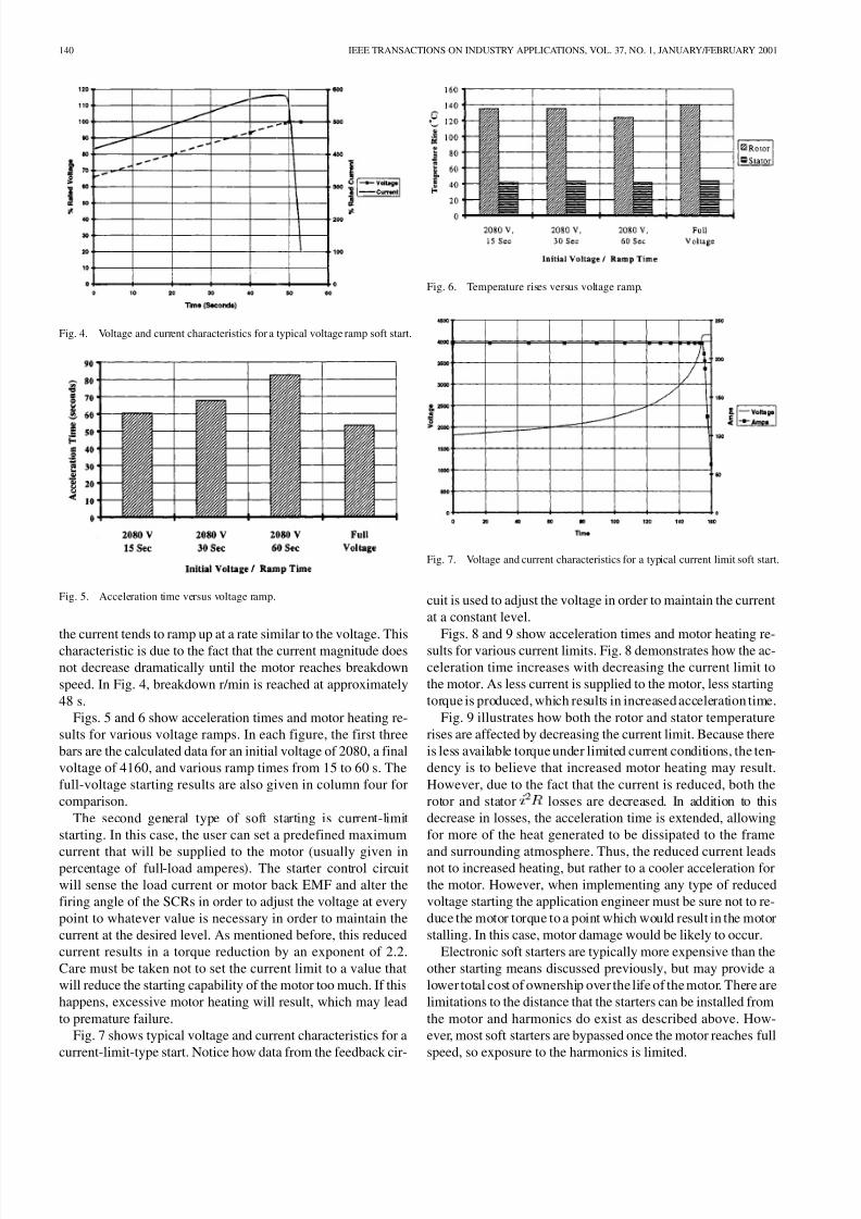
Fig. 4. Voltage and current characteristics for a typical voltage ramp soft start.
Fig. 5. Acceleration time versus voltage ramp.
the current tends to ramp up at a rate similar to the voltage. Thischaracteristic is due to the fact that the current magnitude does
not decrease dramatically until the motor reaches breakdown
speed. In Fig. 4, breakdown r/min is reached at approximately
48 s.
Figs. 5 and 6 show acceleration times and motor heating re-
sults for various voltage ramps. In each figure, the first three
bars are the calculated data for an initial voltage of 2080, a final
voltage of 4160, and various ramp times from 15 to 60 s. The
full-voltage starting results are also given in column four for
comparison.
The second general type of soft starting is current-limit
starting. In this case, the user can set a predefined maximum
current that will be supplied to the motor (usually given inpercentage of full-load amperes). The starter control circuit
will sense the load current or motor back EMF and alter the
firing angle of the SCRs in order to adjust the voltage at every
point to whatever value is necessary in order to maintain the
current at the desired level. As mentioned before, this reduced
current results in a torque reduction by an exponent of 2.2.
Care must be taken not to set the current limit to a value that
will reduce the starting capability of the motor too much. If this
happens, excessive motor heating will result, which may lead
to premature failure.
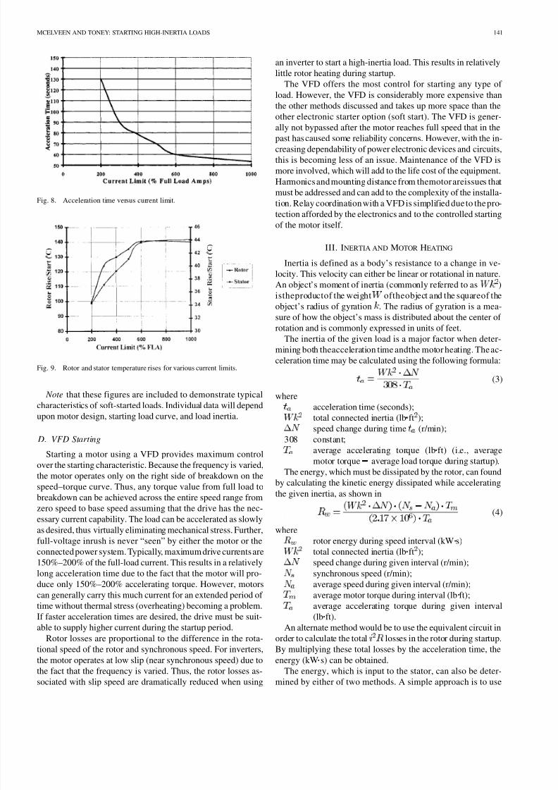
Fig. 7 shows typical voltage and current characteristics for a
current-limit-type start. Notice how data from the feedback cir-
Fig. 6. Temperature rises versus voltage ramp.
Fig. 7. Voltage and current characteristics for a typical current limit soft start.
cuit is used to adjust the voltage in order to maintain the current
at a constant level.
Figs. 8 and 9 show acceleration times and motor heating re-sults for various current limits. Fig. 8 demonstrates how the ac-
celeration time increases with decreasing the current limit to
the motor. As less current is supplied to the motor, less starting
torque is produced, which results in increased acceleration time.
Fig. 9 illustrates how both the rotor and stator temperature
rises are affected by decreasing the current limit. Because there
is less available torque under limited current conditions, the ten-
dency is to believe that increased motor heating may result.
However, due to the fact that the current is reduced, both the
rotor and stator losses are decreased. In addition to this
decrease in losses, the acceleration time is extended, allowing
for more of the heat generated to be dissipated to the frame
and surrounding atmosphere. Thus, the reduced current leadsnot to increased heating, but rather to a cooler acceleration for
the motor. However, when implementing any type of reduced
voltage starting the application engineer must be sure not to re-
duce the motor torque to a point which would result in the motor
stalling. In this case, motor damage would be likely to occur.
Electronic soft starters are typically more expensive than the
other starting means discussed previously, but may provide a
lower total cost of ownership over the life of the motor. There are
limitations to the distance that the starters can be installed from
the motor and harmonics do exist as described above. How-
ever, most soft starters are bypassed once the motor reaches full
speed, so exposure to the harmonics is limited.
8/3/2019 Start Inertia Loads
http://slidepdf.com/reader/full/start-inertia-loads 5/8
MCELVEEN AND TONEY: STARTING HIGH-INERTIA LOADS 141
Fig. 8. Acceleration time versus current limit.
Fig. 9. Rotor and stator temperature rises for various current limits.
Note that these figures are included to demonstrate typical
characteristics of soft-started loads. Individual data will depend
upon motor design, starting load curve, and load inertia.
D. VFD Starting
Starting a motor using a VFD provides maximum control
over the starting characteristic. Because the frequency is varied,
the motor operates only on the right side of breakdown on the
speed–torque curve. Thus, any torque value from full load to
breakdown can be achieved across the entire speed range from
zero speed to base speed assuming that the drive has the nec-
essary current capability. The load can be accelerated as slowly
as desired, thus virtually eliminating mechanical stress. Further,
full-voltage inrush is never “seen” by either the motor or the
connected power system. Typically, maximum drive currents are150%–200% of the full-load current. This results in a relatively
long acceleration time due to the fact that the motor will pro-
duce only 150%–200% accelerating torque. However, motors
can generally carry this much current for an extended period of
time without thermal stress (overheating) becoming a problem.
If faster acceleration times are desired, the drive must be suit-
able to supply higher current during the startup period.
Rotor losses are proportional to the difference in the rota-
tional speed of the rotor and synchronous speed. For inverters,
the motor operates at low slip (near synchronous speed) due to
the fact that the frequency is varied. Thus, the rotor losses as-
sociated with slip speed are dramatically reduced when using
an inverter to start a high-inertia load. This results in relatively
little rotor heating during startup.
The VFD offers the most control for starting any type of
load. However, the VFD is considerably more expensive than
the other methods discussed and takes up more space than the
other electronic starter option (soft start). The VFD is gener-
ally not bypassed after the motor reaches full speed that in the
past has caused some reliability concerns. However, with the in-creasing dependability of power electronic devices and circuits,
this is becoming less of an issue. Maintenance of the VFD is
more involved, which will add to the life cost of the equipment.
Harmonics and mounting distance from themotor areissues that
must be addressed and can add to the complexity of the installa-
tion. Relay coordination with a VFD is simplified due to the pro-
tection afforded by the electronics and to the controlled starting
of the motor itself.
III. INERTIA AND MOTOR HEATING
Inertia is defined as a body’s resistance to a change in ve-
locity. This velocity can either be linear or rotational in nature.An object’s moment of inertia (commonly referred to as )
istheproductof the weight oftheobject and the squareof the
object’s radius of gyration . The radius of gyration is a mea-
sure of how the object’s mass is distributed about the center of
rotation and is commonly expressed in units of feet.
The inertia of the given load is a major factor when deter-
mining both theacceleration time andthe motor heating. The ac-
celeration time may be calculated using the following formula:
(3)
where
acceleration time (seconds);
total connected inertia (lb ft );speed change during time (r/min);
308 constant;
average accelerating torque (lb ft) (i.e., average
motor torque average load torque during startup).
The energy, which must be dissipated by the rotor, can found
by calculating the kinetic energy dissipated while accelerating
the given inertia, as shown in
(4)
where
rotor energy during speed interval (kW s)
total connected inertia (lb ft );speed change during given interval (r/min);
synchronous speed (r/min);
average speed during given interval (r/min);
average motor torque during interval (lb ft);
average accelerating torque during given interval
(lb ft).
An alternate method would be to use the equivalent circuit in
order to calculate the total losses in the rotor during startup.
By multiplying these total losses by the acceleration time, the
energy (kW s) can be obtained.
The energy, which is input to the stator, can also be deter-
mined by either of two methods. A simple approach is to use

8/3/2019 Start Inertia Loads
http://slidepdf.com/reader/full/start-inertia-loads 6/8
142 IEEE TRANSACTIONS ON INDUSTRY APPLICATIONS, VOL. 37, NO. 1, JANUARY/FEBRUARY 2001
the ratio of the stator resistance to the rotor resistance as fol-
lows:
(5)
where
stator energy during speed interval (kW s);
ratio of stator to rotor resistance during speed in-terval;
rotor energy during given interval (kW s).
This method can be derived from the motor equivalent circuit,
given that the magnetizing branch is ignored. The losses are
proportional to the relative magnitudes of the rotor and stator
resistances. Thus, once the rotor energy has been calculated, the
stator energy can be easily obtained using (5).
The second method is to calculate the total losses asso-
ciated with the stator windings as shown in
(6)
where
stator losses during speed interval (kW);stator current during speed interval (amperes);
stator resistance during speed interval (ohms).
Again, by multiplying the total stator losses by the accelera-
tion time, the total energy can be obtained.
Once the energy that must be dissipated by both the rotor and
stator has been determined, the corresponding temperature rises
are found by dividing the kW s by the specific heat ( ) of the
material and the total weight of the material. It is important to
note that temperature rises calculated in this fashion are by ab-
sorption only; that is, all the heat is assumed to go into either the
stator windings or rotor bars and no heat dissipation is assumed.
For acceleration times of only a few seconds, this method is sat-
isfactory. For longer acceleration times, the actual temperaturerises will be lower since conduction, convection, and radiation
will dissipate heat. In this case, it is common practice to cor-
rect the calculated temperature rise by applying reduction fac-
tors that have been determined experimentally.
Table I summarizes the acceleration time, locked-rotor
torque, locked rotor amperes, stator rise/start, and rotor
rise/start for each starting method given above. The motor used
in each calculation is a 500-hp TEFC high-torque (Design C)
four-pole 4160-V motor. The load inertia used was 30 000 lb ft
and the load curve was assumed to be linear from 0 to 1800
r/min, with 190 lb ft of torque required at full-load speed.
Note that Design C-type rotors are not suited for inverter duty
applications due to the harmonic losses and excessive heating inthe small, upper cage. However, this fact has been disregarded
for the sake of comparison. Analyzing starting methods, not
motor design, is the main focus of this paper.
IV. CASE HISTORY (CENTRIFUGE STARTUP)
The load was a chemical plant centrifuge with 30 000 lb ft
of inertia. It was determined that belt slippage and decreased
life would be a problem if some type of reduced voltage/torque
starting was not used. Also, reducing the current draw during
startup would be a benefit. The soft-start manufacturer specified
a motor that would accelerate the centrifuge with a current limit
TABLE IVARIOUS STARTING METHODS SUMMARY
TABLE IITEST DATA SUMMARY
of 225% of full-load amperes. It was critical to be able to calcu-
late the heating that would be experienced by both the rotor and
stator while accelerating this large inertia under reduced torque
conditions.
For this reason, a computer program was developed which
could simulate the torque produced and the current drawn by
the motor at every point during the acceleration time period. By
knowing the torque output of the motor at the reduced current
conditions, the acceleration time and motor heating can be cal-
culated. Using this program, it was determined that the motorwould be suitable to start this load with the specified current
limit without overheating either the rotor or stator. Data was
taken during the actual startup of the motor/load combination
to test the accuracy of the program. Table II summarizes the re-
sults of this startup. Unfortunately, due to plant limitations and
the fact that this was a totally enclosed machine, actual rotor
temperatures could not be recorded.
V. TORQUE EFFICIENCY (TE)
TE has been used in the past to describe a motor’s torque
per ampere ratio. This ratio is a measure of how much output
torque is supplied by a motor for a particular current level. Forexample, if motor A supplies 200% of full load torque at locked
rotor and draws 650% of full-load amperes, its torque efficiency
would be 200/650 = 0.308 or 30.8%. On the other hand, if motor
B supplies the same 200% of full-load torque at locked rotor
and draws only 450% of full load amperes, its torque efficiency
would be 200/450 = 0.444 or 44.4%.
TE can be a major factor when using current limit starting.
Special rotor bar shapes and materials and winding configu-
rations are used to achieve a high TE ratio. A motor with a
higher value of torque efficiency would produce more starting
torque for a given current limit than a motor with a lower TE
value. Thus, if a soft starter were being used on a high-inertia or
8/3/2019 Start Inertia Loads
http://slidepdf.com/reader/full/start-inertia-loads 7/8
MCELVEEN AND TONEY: STARTING HIGH-INERTIA LOADS 143
heavy-load application, a motor with a high TE ratio may be de-
sired. Design C-type motors generally have a high TE ratio as
compared to Design B-type motors. Some easier applications,
such as pumps and compressors may not need a special high TE
motor. Whether or not a special motor is needed is very appli-
cation dependent.
VFDs offer the highest torque efficiency available. Because
VFDs operate on the right-hand side of breakdown, the torqueproduced is roughly proportionate to the current drawn. For ex-
ample, to produce 150% of full-load torque, only about 150% of
full-load current is needed. This results in a torque efficiency of
approximately 150/150 = 1.0 or 100%. For this reason, among
others, VFD starting is the best method when current is limited
and maximum starting torque is required.
VI. METHODS OF CALCULATION
The calculation procedure for both soft starting and inverter
duty starting was implemented utilizing a numerical integration
technique in which the acceleration intervals were broken down
into small sections. Using (3)–(5) and taking into account theharmonics produced by the starter, the calculations were per-
formed for each individual period during acceleration from zero
to full-load speed. Each parameter involved (i.e., losses, accel-
eration times, and heating calculations) was computed for each
of the speed intervals and then totaled to obtain the final result.
By letting these speed intervals approach zero, a very accurate
representation of what is happening during the motor startup is
obtained. As mentioned earlier, the heating calculations were
performed based on absorption only. Empirical factors obtained
from test data were used to correct for dissipation by convec-
tion, radiation, and conduction.
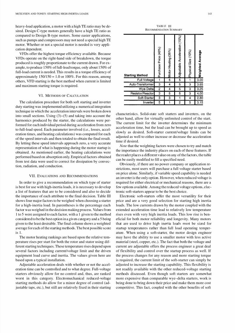
VII. EVALUATIONS AND RECOMMENDATIONS
In order to give a recommendation on which type of starter
is best for use with high-inertia loads, it is necessary to develop
a list of features that are to be considered and also to decide
the importance of each attribute to the final decision. Table III
shows four major factors to be weighed when choosing a starter
for a high-inertia load. In parentheses is the percentage each
factor was weighed in the decision making process. Values from
1 to 5 were assigned to each factor, with a 1 given to the method
considered to be the best option in a given category and a 5 being
given to the least desirable. The final column shows a weighted
average for each of the starting methods. The best possible score
is 1.The motor heating rankings are based upon the relative tem-
perature rises per start for both the rotor and stator using dif-
ferent starting techniques. These temperature rises depend upon
several factors including current/voltage limit and the driven
equipment load curve and inertia. The values given here are
based upon a typical installation.
Adjustable acceleration deals with whether or not the accel-
eration time can be controlled and to what degree. Full-voltage
starters obviously allow for no control and, thus, are ranked
worst in this category. Electromechanical reduced-voltage
starting methods do allow for a minor degree of control (ad-
justable taps, etc.), but still are relatively fixed in their starting
TABLE IIIRECOMMENDATION SUMMARY
characteristics. Solid-state soft starters and inverters, on the
other hand, allow for virtually unlimited control of the start.
The current limit for the inverter determines the minimum
acceleration time, but the load can be brought up to speed as
slowly as desired. Soft-starter current/voltage limits can be
adjusted as well to either increase or decrease the acceleration
time if desired.
Note that the weighting factors were chosen to try and match
the importance the industry places on each of these features. If
the reader places a different value on any of the factors, the table
can be easily modified to fill a specified need.
Obviously, if there are no power company or application re-
strictions, most users will purchase a full voltage starter based
on price alone. Similarly, if variable speed capability is neededan inverter is the only option. However, when reduced voltage is
required for either electrical or mechanical reasons, there are a
few options available. Among the reduced voltage options, elec-
tronic soft-starters appear to be the best choice.
Electronic soft-starters offer the most versatility for their
price and are a very good selection for starting high inertia
loads. The low currents drawn by the motor coupled with the
extended acceleration time lead to relatively low temperature
rises even with very high inertia loads. This low rise is ben-
eficial for both motor reliability and longevity. Many motors
that are used to drive high inertia loads must be sized for
startup temperatures rather than full load operating temper-
ature. When using a soft-starter, the motor design engineermay have the ability to use a smaller motor with less active
material (steel, copper, etc.). The fact that both the voltage and
current are adjustable offers the process engineer a great deal
of flexibility and control over the startup process as well. If
the process changes for any reason and more starting torque
is required, the current limit of the soft-starter can simply be
adjusted to increase the starting capability. This flexibility is
not readily available with the other reduced-voltage starting
methods discussed. Even though soft starters are somewhat
more expensive than comparable wye–delta starters, work is
being done to bring down their price and make them more cost
competitive. This fact, coupled with the other benefits of soft

8/3/2019 Start Inertia Loads
http://slidepdf.com/reader/full/start-inertia-loads 8/8
144 IEEE TRANSACTIONS ON INDUSTRY APPLICATIONS, VOL. 37, NO. 1, JANUARY/FEBRUARY 2001
starters previously mentioned make them a superb choice for
starting high-inertia loads.
VIII. CONCLUSION
Various methods of starting are available for use with high-
inertia loads. Motor heating, acceleration time, and total cost of
ownership are allfactors that must be considered when choosinga specific starter for a high-inertia application. No matter which
starting method is used, it is vital that the motor manufacturer
be advised so that the proper design steps can be taken to be
certain that the motor will perform as desired. More work needs
to be done to investigate further the impact that the harmonics
have on both motor heating and usable motor torque. However,
test data show that the program developed for analyzing soft
starters is reasonably accurate for predicting temperatures and
acceleration times for soft-started motors. Using the weighting
factors chosen and based upon the test results, soft starters are
an excellent choice to start high-inertia load applications when
some type of reduced voltage/current is required.
ACKNOWLEDGMENT
The authors wish to thank F. Heredos for his guidance and
technical assistance. Thanks are also extended to J. Koehler for
his help implementing the programs for both the soft-start and
VFD-start calculations.
REFERENCES
[1] W. McMurray, “A comparative study of symmetrical 3-phase circuitsfor phase-controlled a.c. motor drives,” IEEE Trans. Ind. Applicat., vol.IA-10, pp. 403–411, May/June 1974.
[2] “Bulletin 150 application and product guide,” Allen Bradley Company,Richland Center, WI, 1995.
[3] A. N. Eliasen, “High-inertia drive motors and their starting characteris-tics,” IEEE Trans. Power App. Syst., vol. 99, pp. 1472–1482, July/Aug.1980.
[4] J. F. Heidbreder, “Induction motor temperature characteristics,”presented at the AIEE Fall Meeting, 1955, Paper 55-761.
[5] J. H. Dymond, “Stall time, acceleration time, frequency of starting: Themyths and the facts,” presented at the IEEE Petroleum and ChemicalIndustry Technical Conf., 1991, Paper PCIC-91-03.
Robbie F. McElveen (S’93–M’95) received the B.S. and M.S. degrees fromClemson University, Clemson, SC, in 1993 and 1995, respectively, both in elec-trical engineering.
In 1995, he joined the Custom Motors Group, Reliance Electric-RockwellAutomation, King’s Mountain, NC, as a Motor Design Engineer. His primaryresponsibilities included variable-speed motor design, as well as motor designfor high-inertia applications. In 1999, he joined John Deere, Charlotte, NC, asa Project Engineer.
Michael K. Toney (S’68–M’69–SM’97) received the B.S.E.E. degree from
West Virginia Institute of Technology, Montgomery.Hehas been with Amoco Corporationsince1980andis currentlyan ElectricalEngineering Consultant in the AmocoWorldwide Engineering and ConstructionOffice, Houston, TX. He provides electrical expertise and counsel for refining,production, chemical, and pipeline operations. He is the current Vice-Chairmanof the American Petroleum Institute (API) Refining Subcommittee on ElectricalEquipmentand actively participatedin the1997revision of APIRP 500, thenewAPI RP 505, and the 1998 revision of API RP 14F. His present activities includethe Chemical Manufacturers Association alternate representative on Panel 7 of the National Electrical Code, API’s primary representative on NFPA 70E Em-ployee Safety in the Workplace, and API’s primary representative on NFPA 780Lightning Protection.
Mr. Toney is a member of several national and international technical organi-zations, including The International Society for Measurement and Control, Na-tional Fire Protection Association, Association for Facilities Engineering, andInternational Association of Electrical Inspectors. He is also a member of TauBeta Pi.