stap for gps receiver synchronization - uc santa barbara · stap for gps receiver synchronization...
TRANSCRIPT

STAP for GPS ReceiverSynchronization
SEUNG-JUN KIM
RONALD A. ILTIS, Senior Member, IEEE
A space-time adaptive processing (STAP) algorithm for delay
tracking and acquisition of the GPS signature sequence with
interference rejection capability is developed. The interference
can consist of both broadband and narrowband jammers, and is
mitigated in two steps. The narrowband jammers are modeled as
vector autoregressive (VAR) processes and rejected by temporal
whitening. The spatial nulling is implicitly achieved by estimating
a sample covariance matrix and feeding its inverse into the
extended Kalman filter (EKF). The EKF estimates of the code
delay and the fading channel are used for a t-test for acquisition
detection. Computer simulations demonstrate robust performance
of the algorithm in severe jamming, and also show that the
algorithm outperforms the conventional delay-locked loop (DLL).
Manuscript received November 20, 2002; revised August 7, 2003;released for publication September 30, 2003.
IEEE Log No. T-AES/40/1/826460.
Refereeing of this contribution was handled by L. M. Kaplan.
This work was supported in part by ONR ContractN00014-01-G-0460 and the University of Washington, and by agrant from the International Foundation for Telemetering.
Authors’ address: Dept. of Electrical and Computer Engineering,University of California, Santa Barbara, CA 93106, E-mail:([email protected]).
0018-9251/04/$17.00 c° 2004 IEEE
I. INTRODUCTION
The Global Positioning System (GPS) is asatellite-based network that provides precision 3-Dposition and velocity estimates by tracking thetime-of-arrival of spread spectrum signals. However,due to its extremely weak received signal power,the GPS receiver design must take into account theeffect of RF interferences from either intentional orunintentional sources [1]. Military GPS receivers mustbe able to operate reliably in the presence of maliciousmultiple wideband/narrowband jamming signals [2].It is well known that these interferers can
severely impair synchronization performance ofthe receiver [3]. To partially alleviate the effectsof the interference, one can narrow the bandwidthof the tracking loop, at the expense of increasedpull-in time [1]. However, sophisticated signalprocessing algorithms may be necessary to dealwith challenging multiple jammer scenarios [1, 4, 5].While narrowband interference in GPS systemscan be effectively mitigated using temporal orfrequency-domain filtering [5, 6] widebandinterference must be addressed by taking advantageof the spatial dimension using adaptive antenna arraytechniques.Previous work on interference nulling based
on STAP in GPS receivers includes [2] and [7—9].Assuming that the direction of arrival of the GPSsignal can be obtained from an INS (inertialnavigation system) [1], beam and null steeringtechniques have been developed using criteriasuch as maximum signal-to-interference ratio [7],minimum mean square error [7], and minimumoutput power [8]. However, specific results onsynchronization performance and the integrated designof code synchronization algorithms with space-timeprocessing have not been extensively addressed in theliterature.A tracking and acquisition algorithm for the
GPS C/A code delay using space-time processing isdeveloped here. Instead of preprocessing the samplesof the received signal with a space-time processor andfeeding the output to a conventional synchronizationalgorithm (e.g. a tracking loop), we consider the useof the extended Kalman filter (EKF) to obtain anestimate of the code delay directly from the antennaoutput vectors. The algorithm can also provideestimates of the flat fading channel, narrowbandjammer parameters, and in some cases, even thedirection of arrival of the GPS signal.The narrowband jammers are modeled as
vector autoregressive (VAR) processes and filteredtemporally. The autoregressive (AR) parametricmodel of interference has been used in radar signalprocessing [10—12]. Here, it is shown that exacttemporal whitening can actually be achieved undercertain conditions. For practical implementation, it is
132 IEEE TRANSACTIONS ON AEROSPACE AND ELECTRONIC SYSTEMS VOL. 40, NO. 1 JANUARY 2004

also shown that the VAR coefficient matrices needonly be scaled identity matrices, thus greatly reducingcomputational complexity.The temporally whitened signal vector has only
spatial correlation and an exact analogy to thecode-division multiple-access (CDMA) multiuserdetection problem can be established [13]. To spatiallywhiten the wideband jammers and the residualnarrowband jammer power, we use a moving-averageestimate of the residual correlation matrix and feed itsinverse into the EKF.The t-test [14] is employed in the acquisition
algorithm to address the problem of initial coarsetiming acquisition in the presence of unknownjamming. The EKF estimates of the time delay,channel fading, and possibly the GPS signal steeringvector are utilized to form the acquisition decisionstatistic.The paper is organized as follows. In Section II,
the signal model for the GPS receiver is described. InSection III, the temporal whitening of the narrowbandjamming signals is developed. In Section IV, we applythe EKF to the state-space formulation. Section Vdevelops the space-time acquisition algorithm.Simulation results are given in Section VI, and a shortsummary follows in Section VII.
II. SIGNAL MODEL
The GPS C/A code signal can be modeled as [6]
s(t) = Refp2Psd(t)PN(t)exp(j2¼fct)g (1)
where Ps is the transmitted signal power, d(t) 2f¡1,1g is the binary phase-shift keyed (BPSK)data modulation at 50 bit/s, and fc is the L1 carrierfrequency of 1575.42 MHz [15]. The pseudorandomnoise (PRN) waveform PN(t) is defined by
PN(t) =1X
m=¡1
Lca¡1Xk=0
ckPTc(t¡ kTc¡mTca) (2)
where Lca = 1023 is the length of the C/A codein chips, Tca = 10
¡3 is the period of the C/A PRNsequence given in seconds, Tc = Tca=Lca is thechip duration, and ck 2 f¡1,1g is the C/A codesequence [1]. The pulse function PTc(t) satisfies PTc(t)= 1, t 2 [0,Tc), and zero otherwise.The GPS signal is assumed to be transmitted
through a flat fading channel and corrupted by Kjammers. After the signal is downconverted andlowpass filtered, we can represent the sampledreceived signal vector from the antenna array by
r(n) = a0(n)as(n)d(nTs¡ ¿(n))PNlp(nTs¡ ¿(n))
+KXk=1
ajk (n)jk(n)+n(n): (3)
Here, the Nyquist sampling interval Ts is equal toTc=4 corresponding to the approximate bandwidthof the C/A code signal of 2=Tc. ¿(n) is the timedelay, jk(n) is the kth jamming signal with powerPjk , n(n) is additive white complex Gaussian noisewith covariance ¾2nI, and a
0(n) is the fading channelcoefficient with average power P. The time-varyingfading channel coefficients are modeled as Rician withRice factor K0 and Doppler spread fd Hz. The steeringvector for the desired GPS signal is as(n) and thesteering vector for the kth jammer is ajk (n) . Notealso that PN(t) in (1) is replaced by PNlp(t), whichis the ideal lowpass filtered version of the PRNwaveform, with the cutoff frequency 2=Tc, definedby [16]
PNlp(t) =1X
m=¡1
Lca¡1Xk=0
ck1¼
"Si
µ4¼Tc(t¡ kTc¡mTca)
¡ Siµ4¼Tc(t¡ (k+1)Tc¡mTca)
¶#(4)
where
Si(x)¢=Z x
0
sinyydy: (5)
The signal-to-noise ratio (SNR) in dB after coherentreception is defined by
SNR= 10log10P
¾2n=2(6)
and the jammer-to-signal power ratio J=S for the kthjammer is given by
J=S = 10log10PjkP: (7)
III. TEMPORAL WHITENING
When the jammers are narrowband, the jammingvector can be whitened using a VAR whitening filtergiven by [10]
H(z¡1) = I¡LXl=1
Hlz¡l: (8)
The following theorem shows that we can find theVAR coefficients matrices Hl that achieve exactwhitening when the individual jammers are ARprocesses of order less than or equal to L and thenumber of jammers K is less than or equal to thenumber of antenna array elements M.
THEOREM 1 Assume that each jammer can bedescribed by an AR(L) process given by
jk(n) =LXl=1
µk,ljk(n¡ l)+ ek(n), k = 1,2, : : : ,K
(9)
KIM & ILTIS: STAP FOR GPS RECEIVER SYNCHRONIZATION 133

where µk,l is the associated AR coefficient and ek(n) is awhite noise process. Then the jammer vector defined by
j(n) =KXk=1
ajk jk(n) (10)
with the M-by-1 steering vector for the kth jammerajk can be exactly whitened by the filter given by(8), provided that M ¸K, and the ajk are linearlyindependent.
PROOF From (9) and (10), j(n) can be rewritten as
j(n) =ALXl=1
diag(µ1,l, : : : ,µK,l)j(n¡ l) +Ae(n)
(11)where
A¢=[aj1 (n) aj2 (n) ¢ ¢ ¢ajK (n)] (12)
j(n)¢=[j1(n) j2(n) ¢ ¢ ¢jK(n)]T (13)
e(n)¢=[e1(n) e2(n) ¢ ¢ ¢eK(n)]T: (14)
This can be rewritten as
j(n) =ALXl=1
diag(µ1,l, : : : ,µK,l)(AHA)¡1AHAj(n¡ l) +Ae(n):
(15)Since Aj(n) = j(n), it follows that
j(n) =LXl=1
Hlj(n¡ l) +Ae(n) (16)
where Ae(n) is temporally white and Hl is identifiedas
Hl =Adiag(µ1,l, : : : ,µK,l)(AHA)¡1AH: (17)
The VAR coefficients Hl can be estimated by theleast square error criterion as in [10]
H1,H2, : : : ,HL = arg minH1,H2,:::,HL
nXi=L
°°°°°j(i)¡LXl=1
Hlj(i¡ l)°°°°°2
(18)
and the corresponding RLS algorithm can also bederived. j(i) can be approximated by subtractingfrom the received signal vector r(n) the estimateddesired signal component using the tracking algorithmdescribed in Section IV. However, in practice,estimation of LM2 parameters is cumbersome,leading to much distortion in the desired signal andfailure in the subsequent signal tracking. In fact, thecombination of the RLS-based whitening filter and theEKF cannot claim any optimality. A practically viableapproach is to assume that the “sum” of the jammingsignals is AR, as delineated in the following theorem.
THEOREM 2 Assume that the individual jammers jk(n)are zero-mean wide-sense stationary and uncorrelated
with each other. If the sum of the jamming signalsdefined by
j(n) =KXk=1
jk(n) (19)
can be modeled by an AR(L) process, i.e.,
j(n) =LXl=1
Álj(n¡ l) + e(n) (20)
where e(n) is a white random process with variance ¾2e ,then each (scalar) element of the jammer vector j(n)can be exactly whitened by the whitening filter given by(8), where the VAR matrices Hl are given by ÁlI, with Idenoting the identity matrix.
PROOF The suggested whitening filter output e(n) is
e(n) =LXl=0
Álj(n¡ l) (21)
where Á0 = 1 and Ál =¡Ál, l = 1, : : : ,L. Now computethe correlation matrix Re(n,m)
¢=Efe(n)e(m)Hg.
Re(n,m)
= E
8<:Ã
KXk=1
ajk
LXl=0
Áljk(n¡ l)!Ã
KXk0=1
ajk0
LXl0=0
Ál0 jk0 (m¡ l0)!H9=;
=
KXk=1
ajkaHjk
LXl=0
LXl0=0
ÁlÁ¤l0Rjk (n¡m+ l
0 ¡ l): (22)
Therefore, the diagonal elements of Re(n,m) equal¾2e ±n,m since from (20)
Efe(n)e(m)¤g=KXk=1
LXl=0
LXl0=0
ÁlÁ¤l0Rjk (n¡m+ l
0 ¡ l) = ¾2e ±n,m
(23)
and the diagonal elements of ajkaHjkare always unity.
The vector e(n) is not temporally white as theoff-diagonal elements of Re(n,m) are generallynon-zero for m 6= n. However, by approximating e(n)as white, a more stable algorithm results, since only Lparameters have to be estimated, as opposed to LM2
in (18).It should be noted that after applying Theorem 1,
an exact analogy to the CDMA problem can beestablished if we think of the residual whitening filteroutput as multiuser interference with ajk being theinterfering user’s code sequence [13]. Hence, we canapply a variety of multiuser detection-type methodsthat have already been developed [13, 17, 18].The jammer AR coefficients fÁlg can be
effectively estimated jointly with other parametersincluding the time delay using Kalman filter-typealgorithms. Slightly modifying the assumption (20)
134 IEEE TRANSACTIONS ON AEROSPACE AND ELECTRONIC SYSTEMS VOL. 40, NO. 1 JANUARY 2004

and modeling the sum of the jamming signal andadditive white Gaussian noise as an AR(L) process,we have
j(n) +n(n) =LXl=1
Ál[j(n¡ l)+n(n¡ l)]+ e(n)
(24)
where we assume e(n) to be temporally white.
IV. TRACKING ALGORITHM
To develop an EKF-based tracking algorithm, adynamic model for the parameters to be estimated hasto be assumed. Since the time delay ¿ (n) is generallya non-zero-mean random process, it is reasonable tomodel it as a sum of a zero-mean Markov process anda constant process, both of which are estimated by theEKF [19]. That is,
¿ (n) = ¿m(n) + ¿c(n) (25)
where¿m(n) = f¿¿m(n¡ 1)+ v¿ (n¡ 1)¿c(n) = ¿c(n¡ 1)
(26)
and v¿ (n) is a zero-mean white Gaussian randomprocess with variance ¾2¿ . The time-variation of thejitter process ¿m(n) is set by f¿ , and ¾
2¿ accounts for
its variance. These parameters depend on variousfactors such as the quality of the oscillator used andthe relative motion of the receiver and the spacevehicle (SV), and thus are determined empirically.The constant process ¿c(n) can alternatively beviewed as an extremely narrowband AR processthat accommodates the long-term motion of theplatform. Note that this model is different fromthe simple first-order AR model widely used forthe delay process in the literature in that the sumof a constant and an AR process is in fact anautoregressive moving average (ARMA) process[16, 20].A simple AR model is adopted for the Rician
fading channel. First, a lump parameter a(n) isdefined to be the product of the fading channel a0(n)and the data modulation d(nTs). Then a(n) is modeledas
a(n) = faa(n¡ 1)+ va(n¡ 1): (27)
To take the BPSK data modulation into account,a modification is made for the model at the bitboundary, following [21]. At the bit boundary,
a(n) =
8><>:faa(n¡ 1)+ va(n¡ 1) with probability 1
2
faa(n¡ 1)+ [va(n¡ 1)¡ 2faa(n¡ 1)]with probability 1
2
:
(28)
Therefore, the variance of va(n) is modeled by
¾2a (n) =½¾2a +2f
2a ja(n¡ 1)j2 at the bit boundary
¾2a otherwise
(29)
where fa and the nominal variance ¾2a of the
zero-mean white Gaussian process va(n) aredetermined so that the power spectrum of the fadingprocess closely resembles that of a realistic fadingchannel with the given Rice factor and Dopplerspread. Justification for using an AR fading channelmodel can be found in [22]. It is also straightforwardto extend the model to a higher order AR model[23].The AR parameters for the narrowband jammers
are modeled as zero-mean first order AR processes.
Ál(n) = fÁÁl(n¡ 1)+ vÁl (n¡ 1), l = 1, : : : ,L
(30)
where fÁ and ¾2Á, the variance of the white Gaussian
process vÁl (n), are determined by the dynamics of theparameters.One can rely on external information such as
almanac and/or an INS to get an estimate of thesteering vector for the desired signal as(n) [24], oralternatively, use the proposed algorithm to directlyestimate it. In the latter case, the model
ais(n) = fasais(n¡ 1)+ vas(n¡ 1), i= 2, : : : ,M
(31)
can be used, where ais(n) is the ith component of thevector as(n) and vas(n) has the variance ¾
2as. The first
element of as(n) is not estimated as it is assumedto correspond to the reference antenna element andthus a1s (n) is fixed at 1. Since jais(n)j= 1 for all i, thisnonlinear constraint is applied at every Kalman updatestep to enhance the estimation performance [25].These models can be combined in the plant
equation
x(n) = F(n¡ 1)x(n¡ 1)+ v(n¡ 1) (32)
where the state vector x(n) 2 C3+L+M¡1 is given byx(n) = [¿m(n),¿c(n),a(n),Á1(n),Á2(n), : : : ,
ÁL(n),a2s (n),a
3s (n), : : : ,a
Ms (n)]
T (33)
the transition matrix F(n) is given by
F(n) = diagff¿ ,1,fa,fÁ, : : : ,fÁ| {z }L
,fas , : : : ,fas| {z }M¡1
g (34)
and the zero-mean white Gaussian noise vector v(n)has the covariance matrix given by
Q(n) = diagf¾2¿ ,0,¾2a(n),¾2Á, : : : ,¾2Á| {z }L
,¾2as , : : : ,¾2as| {z }
M¡1
g:
(35)
KIM & ILTIS: STAP FOR GPS RECEIVER SYNCHRONIZATION 135

The measurement model can be identified from (3)and (24) as r(n) 2 CM
r(n) = h(x(n),rL)+ e(n) (36)
= a(n)as(n)PNlp(nTs¡ ¿ (n))
+LXl=1
Ál(n)[r(n¡ l)¡ a(n)as(n)PNlp((n¡ l)Ts¡ ¿ (n))]
+ e(n) (37)
where rL is defined by fr(n¡ 1),r(n¡2), : : : ,r(n¡L)gand e(n) is assumed to be zero-mean white Gaussianwith covariance Re(n). a(n) and as(n) are assumed tobe constant over LTs s.Due to the nonlinear measurement function h(¢), a
closed-form solution for the recursive Bayesian stateestimator cannot be obtained. The most widely usedsuboptimal solutions include the EKF and Gaussiansum filter (GSF) [26]. The EKF is employed heresince the delay estimation error nominally falls in therange of 10¡3Tc to 10
¡6Tc for the GPS code trackingapplication. Therefore the first-order linearizationapproximation for the delay estimate may be welljustified. The linearization of the measurementfunction about the predicted state vector estimatex(n j n¡1) at time n given the measurements up totime n¡ 1 is given byh(x(n),rL)¼ h(x(n j n¡ 1),rL)+H(n)[x(n)¡ x(n j n¡ 1)]
(38)
where H(n)¢=H(x(n j n¡ 1),rL) 2CM£(3+L+M¡1) is the
Jacobian defined by
H(x,rL) =@h(x,rL)@x
(39)
which is again given by H= [h1 h2 ¢ ¢ ¢hM+L+2], whereh1 = h2 =¡a(n)as(n)PNd(nTs¡ ¿ (n))
+LXl=1
Ál(n)a(n)as(n)PNd((n¡ l)Ts¡ ¿(n))
h3 = as(n)PNlp(nTs¡ ¿(n))
¡LXl=1
Ál(n)as(n)PNlp((n¡ l)Ts¡ ¿ (n))(40)
hi+3 = r(n¡ i)¡ a(n)as(n)PNlp((n¡ i)Ts¡ ¿(n)),i= 1, : : : ,L
hi+L+3 = ei+1
"a(n)PNlp(nTs¡ ¿ (n))
¡LXl=1
Ál(n)a(n)PNlp((n¡ l)Ts¡ ¿ (n))#,
i= 1, : : : ,M ¡ 1.
Here, PNd(t) is the derivative of PNlp(t) and eiis a unit column vector with one for the ithelement.In order to formulate the EKF update equations,
the correlation matrix for the white measurementprocess e(n) must be estimated. A moving-averageestimate of the residual correlation matrix givenby [27] is used as follows
R(n) =1NR
n¡1Xl=n¡NR
[r(l)¡h(x(l j l¡ 1),rL)]
£ [r(l)¡h(x(l j l¡ 1),rL)]H: (41)
The EKF update equation can now be written
P¡1(n j n) = P¡1(n j n¡ 1)+HH(n)R¡1(n)H(n)
x(n j n) = x(n j n¡1)+P(n j n)HH(n)R¡1(n)£ [r(n)¡h(x(n j n¡ 1))]
x(n+1 j n) = Fx(n j n)P(n+1 j n) = FP(n j n)FT+Q:
(42)
Since the state vector estimate x is complex ingeneral, the time delay estimate is obtained by takingthe real part of the corresponding complex estimate,e.g.,
¿(n j n) = Ref¿m(n j n)+ ¿c(n j n)g (43)
where ¿m(n j n) and ¿c(n j n) are the first and thesecond elements of x(n j n), respectively. It isnoteworthy that R¡1(n) actually nulls the jammersspatially in (42) since, if the jammer power dominatesthe background noise power, R¡1(n) approaches(1=¾2n)(I¡A(AHA)¡1AH), which is a linear projectorto the left nullspace of A [9]. Therefore, thebroadband jammers, which cannot be whitenedtemporally, are rejected spatially at this stage.The block diagram for the overall tracking
algorithm is given in Fig. 1.
V. ACQUISITION ALGORITHM
In order for the EKF-based tracking algorithmto operate properly, the initial time delay estimatemust be set to a value that is within half a chip ofthe true delay. This coarse acquisition of the delaycan be accomplished by means of a binary hypothesistest. Consider the temporally whitened sequence y(n)defined by
y(n) = r(n)¡LXl=1
Álr(n¡ l)
= a(n)as(n)g(¿(n)) + e(n) (44)
136 IEEE TRANSACTIONS ON AEROSPACE AND ELECTRONIC SYSTEMS VOL. 40, NO. 1 JANUARY 2004
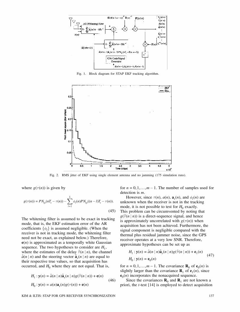
Fig. 1. Block diagram for STAP EKF tracking algorithm.
Fig. 2. RMS jitter of EKF using single element antenna and no jamming (175 simulation runs).
where g(¿(n)) is given by
g(¿(n)) = PNlp(nTs¡ ¿(n))¡LXl=1
Ál(n)PNlp((n¡ l)Ts¡ ¿(n)):
(45)
The whitening filter is assumed to be exact in trackingmode, that is, the EKF estimation error of the ARcoefficients fÁlg is assumed negligible. (When thereceiver is not in tracking mode, the whitening filterneed not be exact, as explained below.) Therefore,e(n) is approximated as a temporally white Gaussiansequence. The two hypotheses to consider are H1,where the estimates of the delay ¿(n j n), the channela(n j n) and the steering vector as(n j n) are equal totheir respective true values, so that acquisition hasoccurred, and H0 where they are not equal. That is,
H1 : y(n) = a(n j n)as(n j n)g(¿(n j n)) + e(n)
H0 : y(n) = a(n)as(n)g(¿(n)) + e(n)(46)
for n= 0,1, : : : ,m¡ 1. The number of samples used fordetection is m.However, since ¿(n), a(n), as(n), and Ál(n) are
unknown when the receiver is not in the trackingmode, it is not possible to test for H0 exactly.This problem can be circumvented by noting thatg(¿(n j n)) is a direct-sequence signal, and henceis approximately uncorrelated with g(¿ (n)) whenacquisition has not been achieved. Furthermore, thesignal component is negligible compared with thethermal plus residual jammer noise, since the GPSreceiver operates at a very low SNR. Therefore,approximate hypotheses can be set up as
H1 : y(n) = a(n j n)as(n j n)g(¿(n j n))+ e1(n)H0 : y(n) = e0(n)
(47)
for n= 0,1, : : : ,m¡ 1. The covariance R0 of e0(n) isslightly larger than the covariance R1 of e1(n), sincee0(n) incorporates the nonacquired sequence.Since the covariances R0 and R1 are not known a
priori, the t-test [14] is employed to detect acquisition
KIM & ILTIS: STAP FOR GPS RECEIVER SYNCHRONIZATION 137

Fig. 3. RMS jitter for four-element antenna array with no jamming (100 simulation runs).
and can be expressed as follows:
t(m) =maxR1 p(y
m jH1,R1)maxR0 p(y
m jH0,R0)H1?H0
t0 (48)
where ym = fy(0),y(1), : : : ,y(m¡ 1)g and t0 is thedetection threshold. Thus the t-test coincides withthe generalized likelihood ratio test (GLRT) [28].With a(n) and as(n) fixed, the maximum likelihoodestimates (MLEs) of R1(n) and R0(n) are givenby
R1(m) =1m
m¡1Xn=0
[y(n)¡ a(n j n)as(n j n)g(¿ (n j n))]
£ [y(n)¡ a(n j n)as(n j n)g(¿(n j n))]H
R0(m) =1m
m¡1Xn=0
y(n)y(n)H:
(49)
By substituting these into (48), and under theassumption of white Gaussian residuals ei(n), thet-statistic reduces to
t(m) =jR0(m)jjR1(m)j
: (50)
VI. SIMULATION RESULTS
The performance of the proposed algorithm wasevaluated by simulation. The antenna array consideredconsists of a four-element square configuration withhalf-wavelength spacing. Both narrowband andwideband jamming signals are considered. The K1narrowband jamming signals are assumed to be swept
TABLE IDirections of Desired Signal and Jamming Signals
as aj1 aj2 aj3 aj4 aj5
Azimuth 85± 288± 216± 120± 240± 5±Elevation 27± 80± 80± 80± 80± 80±
tones defined by
jk(n) =pJk exp(j2¼(¢fk +
_¢fknTs)nTs)
k = 1, : : : ,K1 (51)
where 2 _¢fk is the sweep rate. The K2 widebandjamming signals jk(n) for k =K1 +1, : : : ,K1 +K2are assumed to be zero-mean white Gaussian. TheSNR (6) is assumed to be ¡12 dB and a J=S ratioof 60 dB is used throughout the simulations. Thedirections of the desired GPS signal and the jammersused in the simulations are tabulated in Table I.For the operation of the EKF, the AR model
parameters must be determined. fa = 0:9946 and¾2a = 0:0034123 are used, corresponding to a fadingchannel characterized by fd = 5 kHz and K0 = 15 dB.The timing jitter is modeled by f¿ = 0:9999 and ¾
2¿ =
10¡12, which yield a time constant of approximately10,000 samples and a jitter on the order of 10¡6.Similarly, fas = fÁ = 0:9999 and ¾
2as= ¾2Á = 10
¡3
are chosen for the simulation. Note that perfectknowledge of these parameters is assumed by theEKF. In practice, they must be measured or fine-tunedfor proper operation of the EKF.Fig. 2 shows the rms error of the EKF-based
tracking algorithm when only a single antennaelement is used and no jamming signal is applied.The initial estimation error is assumed to be uniformlydistributed over [¡ 1
2Tc,12Tc]. The average was obtained
138 IEEE TRANSACTIONS ON AEROSPACE AND ELECTRONIC SYSTEMS VOL. 40, NO. 1 JANUARY 2004

Fig. 4. Steering vector estimates for desired signal from 85±.(a) At 1023rd chip. (b) At 5155th chip. (c) At 15345th chip.
(d) At 30690th chip.
from 175 independent simulation runs. Also, thewindow size NR for forming the sample covariancematrix R(n) is set to 200 samples. The rms valueof the error converges to 3:5£ 10¡3Tc at the end of51150 chips, or 0.05 s. This reveals that the modelfor the delay process ¿ (n) given by (25) and (26)can yield good error performance for the EKF-basedtracker even at a low SNR. This is contrary to thereports of poor performance of the EKF-basedalgorithms at low SNR environments as in [20], whichdid not take into account the non-zero mean of theunderlying delay process. Also shown in Fig. 2 isthe rms error of a simple first-order delay-lockedloop (DLL) for comparison. The update equation for
Fig. 5. RMS jitter under three narrowband and two wideband jammers (100 simulation runs).
the DLL is given by a discrete-time version of thenoncoherent DLL in [29]
¿(nN) = ¿((n¡ 1)N) +¹TcÃjye(n)j ¡ jyl(n)j
jyp(n)j
!(52)
where
ye(n) =nNX
k=(n¡1)N+1r(k)PNlp(kTs¡ ¿ ((n¡ 1)N)¡Tc=2)
yp(n) =nNX
k=(n¡1)N+1r(k)PNlp(kTs¡ ¿ ((n¡ 1)N)) (53)
yl(n) =nNX
k=(n¡1)N+1r(k)PNlp(kTs¡ ¿ ((n¡ 1)N)+Tc=2)
and r(k) is given by (37), with r(k) reduced to ascalar. ¹ and N are design parameters that determinethe transient time and the jitter performance. Inthe simulation they are chosen to be ¹= 0:1 andN = 4096 samples. Recall that the transient and jitterperformance of the DLL is a trade-off. From Fig. 2, itcan be seen that the EKF-based tracker outperformsthe DLL in terms of both pull-in time and jitterperformance.Fig. 3 depicts the rms jitter of the proposed
algorithm averaged over 100 simulation runs in theabsence of jamming. Also plotted is the performanceof the simple DLL for comparison. The DLL assumesthe steering vector as to be known a priori, and usesaHs r(k) in place of r(k) in (53). Again, it is clear thatthe EKF-based algorithm exhibits less pull-in timeand rms jitter. Note that the EKF is also estimatingas. The steering vector estimated by the EKF isshown in Fig. 4 at different iterations by plottinga(µ,27±)H as(n), 0
± · µ < 360±, where a(µ,27±) is the
KIM & ILTIS: STAP FOR GPS RECEIVER SYNCHRONIZATION 139

Fig. 6. Effective frequency response of whitening filter for one tone jammer and two swept CW jammers.
Fig. 7. Null pattern formed by R¡1.
steering vector for the four-element planar array atazimuth µ and elevation 27±.Fig. 5 shows the performance of the EKF-based
tracking algorithm under mixed jamming. There are atotal of five jammers. Three narrowband jammers haveparameters ¢f1 =¢f2 = 0, ¢f3 = 1:023 MHz and_¢f1 = 0,
_¢f2 =_¢f3 = 2 GHz. Two wideband jammers
are white Gaussian. In the figure, it is clear that thetemporal whitening with L= 6 is very effective inmitigating the jamming signal, compared with thecase where L= 0, i.e., where the temporal whiteningis turned off. Although not depicted in the figure, therms jitter for the single antenna case without temporalwhitening was observed to quickly increase within afew iterations.
In Fig. 6, the effective time-varying frequencydomain response of the whitening filter is plottedunder the same jamming condition as in Fig. 5,to illustrate its capability to reject the narrowbandjammers. The effective frequency response iscalculated by
H(ej2¼f) = 1¡LXl=1
Ále¡j2¼fl: (54)
It can be seen that the “notches” of the whiteningfilter follow the instantaneous frequencies of thestationary and swept-tone jammers to null out thejamming signal.Fig. 7 shows the ability of the proposed
algorithm to null the wideband jammers by plotting
140 IEEE TRANSACTIONS ON AEROSPACE AND ELECTRONIC SYSTEMS VOL. 40, NO. 1 JANUARY 2004

Fig. 8. ROC of acquisition algorithm without jamming.
Fig. 9. ROC of acquisition algorithm under two narrowband and one wideband jammers.
a(µ,80±)HR¡1as(n) for 0± · µ < 360±, where 80±
corresponds to the jammer elevation. It is observedthat deep nulls are placed in the direction of thejammers, including those of the wideband jammers,which have not been attenuated by temporalwhitening.The acquisition performance of the t-test-based
detector is evaluated by simulation. Fig. 8 shows
the receiver operating characteristic (ROC) of theproposed detector when SNR=¡12 dB and nojamming is present. The probabilities are averagedover 10,000 independent runs. It is observed thatwhen the number of observed samples m¸ 1000,reliable performance for acquisition is obtained. Fig. 9shows the detector performance when two narrowbandand one wideband jammers are present. For the
KIM & ILTIS: STAP FOR GPS RECEIVER SYNCHRONIZATION 141

Fig. 10. Mean acquisition time of proposed algorithm. (a) Without jamming. (b) With jamming.
narrowband jammers, ¢f1 =¢f2 = 0 and_¢f1 = 0,
_¢f2 = 2 GHz were used. The jammer directionsare 288± and 216± in azimuth for the narrowbandjammers, and 120± for the wideband jammer. Theelevation is fixed at 80± and J=S = 60 dB for alljammers. The probabilities are averaged over 2,300independent runs. It can be seen that m¸ 15,000gives acceptable detection and false alarm probabilitiesunder the given jamming condition.Fig. 10 shows the worst case mean acquisition
time Tacq for the algorithm when the simple serialsearch scheme is employed with and withoutjamming, computed from the simulation resultsassociated with Fig. 8 and Fig. 9. Therefore, thejamming condition is the same as in Fig. 9. The worstcase refers to the case where the whole uncertaintyregion of the unknown code phase is searched atleast once. Tacq in number of dwells can be computedby [30, 31]
Tacq =1pD[(D¡ 1)pF(Ns¡1)+Ns] (55)
where pD and pF are the detection and false alarmprobabilities, D is the false alarm penalty time innumber of dwells, and Ns is the number of trialdelays. In Fig. 10, D was set to 20460 chips and Nswas set to 2,046 trial delays, corresponding to thephase update of a half chip.
VII. CONCLUSION
A code synchronization algorithm with integratednarrowband/wideband jamming mitigation for GPS
signals has been developed. The vector input fromthe antenna array was first whitened temporally toreject the narrowband jamming signals. The temporalwhitener output was then processed by the EKFto approximate the minimum variance estimatesof the time delay, flat fading channel, jammer ARparameters, and the steering vector of the desiredsignal. Spatial nulling of the wideband jammers wasimplicitly achieved by means of the estimated residualcorrelation matrix, whose inverse approaches theprojector to the left nullspace of the jammer subspace.To get the initial coarse estimate of the time delay,an acquisition algorithm based on the t-test has alsobeen developed. The performance of the tracking andacquisition algorithms was evaluated by numericalsimulations and shown to reliably acquire and trackthe desired timing in the presence of strong multiplejammers.
REFERENCES
[1] Kaplan, E. (1996)Understanding GPS: Principles and Applications.Boston: Artech House, 1996.
[2] Fante, R., and Vacarro, J. (1998)Cancellation of jammers and jammer multipath in a GPSreceiver.IEEE Aerospace and Electronic Systems Magazine, 13(Nov. 1998), 25—28.
[3] Braasch, M. S., and van Dierendonck, A. J. (1999)GPS receiver architectures and measurements.Proceedings of the IEEE, 87 (Jan. 1999), 48—64.
[4] Parkinson, B. W., and Spilker, J. J., Jr. (Eds.) (1996)Global Positioning System: Theory and Applications.Washington D.C.: American Institute of Aeronautics andAstronautics, Inc., 1996.
142 IEEE TRANSACTIONS ON AEROSPACE AND ELECTRONIC SYSTEMS VOL. 40, NO. 1 JANUARY 2004

[5] Rifkin, R., and Vaccaro, J. J. (2000)Comparison of narrowband adaptive filter technologiesfor GPS.In Proceedings of the IEEE 2000 Position Location andNavigation Symposium, Piscataway, NJ, 2000, 125—131.
[6] Iltis, R., and Hanson, G. (1999)C/A code tracking and acquisition with interferencerejection using the extended Kalman filter.In ION National Technical Meeting Proceedings, SanDiego, CA, Jan. 1999, 881—890.
[7] Fante, R., and Vacarro, J. (2000)Wideband cancellation of interference in a GPS receivearray.IEEE Aerospace and Electronic Systems, 36 (Apr. 2000),549—564.
[8] Myrick, W. L., Goldstein, J. S., and Zoltowski, M. D. (2001)Low complexity anti-jam space-time processing for GPS.In Proceedings of the IEEE International Conference onAcoustics, Speech, and Signal Processing, Salt Lake City,UT, May 2001, 2233—2236.
[9] Zoltowski, M. D., and Gecan, A. S. (1995)Advanced adaptive null steering concepts for GPS.In Proceedings of MILCOM ’95, San Diego, CA, Nov.1995, 1214—1218.
[10] Swindlehurst, A. L., and Stoica, P. (1998)Maximum likelihood methods in radar array signalprocessing.Proceedings of the IEEE, 86 (Feb. 1998), 421—441.
[11] Parker, P., and Swindlehurst, A. L. (2001)A parametric approach to hot clutter cancellation.In Proceedings of IEEE International Conference onAcoustics, Speech, and Signal Processing, Salt Lake City,UT, May 2001, 2909—12.
[12] Roman, J. R., Rangaswamy, M., Davis, D. W., Zhang, Q.,Himed, B., and Michels, J. H. (2000)Parametric adaptive matched filter for airborne radarapplications.IEEE Aerospace and Electronic Systems, 36 (Apr. 2000),677—692.
[13] Verdu, S. (1998)Multiuser Detection. New York: Cambridge UniversityPress, 1998.
[14] Helstrom, C. W. (1995)Elements of Signal Detection and Estimation.Englewood Cliffs, NJ: Prentice-Hall, 1995.
[15] Hofmann-Wellenhof, B., Lichtenegger, H., and Collins, J.(1994)GPS Theory and Practice.New York: Springer-Verlag, 1994.
[16] Iltis, R. A. (1994)An EKF-based joint estimator for interference, multipath,and code delay in a DS spread-spectrum receiver.IEEE Transactions on Communication, 42 (Feb.—Apr.1994), 1288—1299.
[17] Madhow, U., and Honig, M. L. (1994)MMSE interference suppression for direct-sequencespread-spectrum CDMA.IEEE Transactions on Communication, 42 (Dec. 1994),3178—3188.
[18] Miller, S. L. (1995)An adaptive direct-sequence code-division multiple-accessreceiver for multiuser interference rejection.IEEE Transactions on Communication, 43 (Feb./Mar./Apr.1995), 1746—1755.
[19] Bona, B. E., and Smay, R. J. (1966)Optimum reset of ship’s inertial navigation system.IEEE Aerospace and Electronic Systems, AES-2 (July1966), 409—414.
[20] Diaz, P., and Agusti, R. (1997)A novel EKF-based scheme for tracking code delayrecovery in DS/CDMA systems.International Journal of Wireless Information Networks, 4(Apr. 1997), 89—100.
[21] Lim, T. J., and Rasmussen, L. K. (1997)Adaptive symbol and parameter estimation inasynchronous multiuser CDMA detectors.IEEE Transactions on Communication, 45 (Feb. 1997),213—220.
[22] Wu, H-Y., and Duel-Hallen, A. (1996)On the performance of coherent and noncoherentmultiuser detectors for mobile radio CDMA channels.In Proceedings of the International Conference onUniversal Personal Communications, Cambridge, MA, Oct.1996, 76—80.
[23] Kim, S-J., and Iltis, R. A. (2002)Performance comparison of particle and extendedKalman filter algorithms for GPS C/A code tracking andinterference rejection.In Proceedings of the 36th Annual Conference onInformation Sciences and Systems (available as aCD-ROM), Mar. 2002.
[24] Qi, H., and Moore, J. B. (2002)Direct Kalman filtering approach for GPS/INSintegration.IEEE Aerospace and Electronic Systems, 38 (Apr. 2002),687—692.
[25] Tsai, S., Wong, T., and Lehnert, J. (2001)DS-CDMA system with joint channel estimation andMAP detection in time-selective fading channels.IEEE Journal on Sel. Areas Communication, 19 (Jan.2001), 121—131.
[26] Anderson, B., and Moore, J. (1979)Optimal Filtering.Englewood Cliffs, NJ: Prentice-Hall, 1979.
[27] Bensley, S. E., and Aazhang, B. (1996)Subspace-based channel estimation for code divisionmultiple access communication systems.IEEE Transactions on Communication, 44 (Aug. 1996),1009—1020.
[28] Hu, C., Reed, I., Yu, X., and Thanyasrisung, P. (2001)Code timing acquisition using an antenna arrayfor asynchronous DS-CDMA systems in a near-farenvironment.In Proceedings of IEEE International Conference onAcoustics, Speech, and Signal Processing, Vol. 4, May2001, 2213—16.
[29] Ziemer, R. E., and Peterson, R. L. (1985)Digital Communications and Spread Spectrum Systems.New York: Macmillan, 1985.
[30] Iltis, R. A. (1996)Demodulation and code acquisition using decorrelatordetectors for QS-CDMA.IEEE Transactions on Communication, 44 (Nov. 1996),1553—1560.
[31] Polydoros, A., and Weber, C. L. (1984)A unified approach to serial search spread-spectrum codeacquisition–I: General theory.IEEE Transactions on Communications, COM-32 (May1984), 550—560.
KIM & ILTIS: STAP FOR GPS RECEIVER SYNCHRONIZATION 143

Seung-Jun Kim received the B.S. and M.S. degrees in electrical engineering fromSeoul National University, Seoul, Korea, in 1996 and 1998, respectively.From 1998 to 2000, he served as a Korea Overseas Volunteer at Chaing
Rai Teacher’s College, Chaing Rai, Thailand. In 2001, he was with GCTSemiconductor, Seoul, Korea. Since 2001, he has been with the Universityof California, Santa Barbara, working toward a Ph.D. degree in electricalengineering. His current research interests lie in synchronization, channelestimation, and adaptive antenna array beamforming.
Ronald Iltis (S’83–M’84–SM’91) received the B.A. in biophysics fromJohns Hopkins University, Baltimore, MD, in 1978, the M.Sc. in engineeringfrom Brown University, Providence, RI, in 1980, and the Ph.D. in electricalengineering from the University of California, San Diego, in 1984.Since 1984, he has been on the faculty of the Department of Electrical and
Computer Engineering at the University of California, Santa Barbara, wherehe is currently an associate professor. His current research interests are inspread-spectrum communications, blind equalization, multisensor/multitargettracking, and neural networks. He has also served as a consultant to governmentand private industry in the areas of adaptive arrays, neural networks, andspread-spectrum communications.Dr. Iltis was previously an editor for the IEEE Transactions on
Communications. In 1990 he received the Fred W. Ellersick award for best paperat the IEEE MILCOM Conference.
144 IEEE TRANSACTIONS ON AEROSPACE AND ELECTRONIC SYSTEMS VOL. 40, NO. 1 JANUARY 2004