standing committee on power system planning in...
TRANSCRIPT

Standing Committee on Power System Planning in Northern Region
Summary record of discussions in the 23rd meeting of the Standing Committee Meeting on Power System Planning of Northern Region held on 16th February 2008 at Dehradun
1. Confirmation of minutes of 22nd meeting Minutes of 22nd meeting of the Standing Committee held on 12.3.2007 at
Udaipur issued vide letter no. 1/9/2004-SP&PA/135-150 dated 13.04.07 and
subsequent corrigendum issued vide letter no. 1/9/2007-SP&PA/540-555 dated
15.06.07 were confirmed.
2. Review of progress on Earlier Agreed Transmission schemes
Status of progress on earlier agreed schemes is enclosed at Annex-1.
RVPNL requested that works for the 220 kV bays at Bhiwadi and 400/220 kV
transformer provision at Kota may be expedited.
3. Evacuation of power from Jhajjar TPS (1500 MW) 3.1 Jhajjar TPS (3x500 MW) would be located near Jhajjar, Haryana and would be
developed by M/s Aravalli Power Corporation Limited and the beneficiaries of the
power from Jhajjar are Delhi and Haryana in the ratio of 50:50.
Members noted the following evacuation systems for Jhajjar TPS.
To be constructed by generation developer for Delhi
• Jhajjar - Mundka 400 kV D/C line (the line would feed 400/220 kV
transformers and further 220 kV system radially from Mundka not
connecting to Delhi ring)
To be constructed by HVPNL for Haryana
(i) Jhajjar - Daulatabad 400 kV D/C line
(ii) Daulatabad 400 kV S/S
(iii) Daulatabad - Gurgaon (PGCIL sector-72) 400 kV D/C

2
3.2 Connectivity of Daulatabad with Gurgaon (PGCIL sector-72) s/s was concurred
with provision that 400 kV bays at Gurgaon PGCIL would be provided by
PGCIL at the cost of HVPNL.
3.3 PGCIL suggested that Agra-Samaypur and Samaypur-Gurgaon 400kV S/C lines
could be delinked from Samaypur and made as direct Agra-Gurgaon line as this
would facilitate to substantially reduce short circuit level at several sub station
around Delhi. The proposal was agreed to.
4. Transmission system associated with Dadri II TPS (2x490 MW) 4.1 NTPC was putting up extension at Dadri Thermal by adding 2 more unit of 490
MW each with benefit of power to Delhi and U.P. in the ratio of 90:10. The
evacuation arrangement to be provided by NTPC for Delhi was agreed as
following:-
(i) 400 kV Dadri - Bamnoli quad D/C line routed via Maidangarhi where DTL
had proposed a 400kV s/s in the next phase. The 400kV line from Dadri to
Bamnoli would be on multicircuit tower sharing the row of existing
Badarpur-Mehrauli-Bamnoli 220kV line wherever necessary.
(ii) 400 kV bus at Dadri to be split into two portions in order to contain the
short circuit level and the transmission lines emanating from Dadri
switchyard to be rearranged as follows :-
On one section:
• Thermal units of stage-I
• Circuits to Panipat, Muradnagar and Bamnoli
On other section
• Gas Plant units and thermal units of stage-II
• HVDC interconnectors
• Circuits to Mandola and Malerkotla
• Circuits to Samaypur/Maharanibagh/Greater Noida

3
4.2 For evacuation of UP's share of 10% from Dadri-II, UP had proposed for
providing two numbers of 220 kV feeder from Dadri 220 kV switchyard to their
220kV s/s at Dadri. UP also intimated their plan to interconnect their Dadri 220kV
s/s with Muradnagar 400/220kV s/s. It was noted that if this proposal was
implemented, there was a possibility of parallel 400 kV and 220 kV circuits in
operation leading to increased short circuit level which was already critical in the
area. An alternative proposal of providing 220 kV line to Dadri 220 kV s/s of
UPPCL from Hapur where a 400/220kV regional s/s to be established by LILO of
Bareilly - Meerut 400 kV D/C line was also discussed. Technically, this would be
a better option from the considerations of short circuit level as well as from
operational reliability. However, in this, the supply to UP would be through
displacement and if transmission charges and losses for displacement wheeling
were levied of UP, this would become an unduly expansive option for UP. In
view of these considerations, it was agreed by all that delivery of its share to U.P
from Dadri-II would be made available at Hapur by displacement without any
wheeling charges or wheeling losses or any other tariff implications or
transmission loss implications as a special case.
4.3 UPPCL stated that they had a plan for 765 kV s/s at Hapur which would receive
power from Anpara C, D & E. Member (PS), CEA stated that transmission
planning of States network at 400kV and above could not be done in isolation.
He asked UPPCL to furnish their proposal to CEA for necessary examination
and planning an integrated system.
5. Transmission system associated with Bawana CCGT (1500 MW) 5.1 Bawana CCGT (1500 MW) in North West of Delhi at Bawana being developed
by IPGCL would provide benefit to Delhi. The generation at Bawana as per
IPGCL was expected in 2009 before the ensuing Commonwealth Games in
2010. While evolving the evacuation system from Bawana CCGT, considering
the issue of fault level condition existing in Delhi network, it was decided that
power from Bawana would be fed to Delhi loads radially with the following
evacuation system to be developed by generation developer/DTL.
(i) Stepping up the generation of Bawana CCGT at 400 kV

4
(ii) Splitting 400kV as well as 220kV bus at Bawana 400kV s/s of DTL to
provide a separate 400kV and 220kV bus not connected to Delhi 400kV
ring with the split bus side to have 2 nos of 400/220 kV, 315 MVA
transformer and 220kV feeders.
(iii) Connecting Bawana CCGT to split bus side of Bawana 400kV s/s through
bus extension.
(iv) Shifting 2x315 MVA 400/220kV transformer and 220kV outgoing feeders
on the split bus side of Bawana 400kV s/s.
(v) Creation of 2 nos. of new 400/220 kV, 2x500 MVA S/S -one in the North
Delhi and one near Loni Road.
(vi) Bawana CCGT -North Delhi (new) 400kV s/s -Loni Road (new) 400kV s/s
400 kV D/C quad line
(vii) Additional 220 kV feeder bus from 220 kV bus to load centres at Peeragarhi
and arounds to Shalimarbagh etc. where Discomes would develop 66kV ,
33kV feeder.
5.2 For connectivity of the Bawana CCGT with the rest of the grid, basically to
provide support to the power station under contingency and at the same time
addressing the issue of short circuit level, it was proposed that the 400 kV D/C
line from Bawana to Bahadurgarh/Hissar could be de-linked from Delhi 400kV
ring and shifted to the split bus side of Bawana 400kV s/s connecting to Bawana
CCGT switchyard 400 kV bus.
The proposal of shifting of Bawana-Bahadurgarh/Hissar 400kV line was
discussed. PGCIL stated that in the present system, this provided an alternate
path for flow of power in the event of disturbance and separation of East-West
corridor of Northern Region. In order to retain the alternate path, it was also
decided that the existing link between Bawana-Bahadurgarh/Hissar would be
shifted only after the 400 kV Abdullapur-Sonepat- Bahadurgarh D/C line was
commissioned.
Considering the urgency of the system associated with Bawana CCGT, it was
also decided that construction of 400 kV Abdullapur-Sonepat- Bahadurgarh D/C
line would be expedited and though Abdullapur-Sonepat section of this link was

5
evolved as part ATS for Karcham Wangtoo and only Sonepat-Bahadurgarh
section evolved as system strengthening, as this had become an urgent system
strengthening, transmission charges for both lines viz. Abdullapur-Sonepat as
well as Sonepat- Bahadurgarh would be payable as soon as commissioned not
linked to commissioning schedule of Karcham Wangtoo HEP or any other
generation project.
6.0 Region System Strengthening Scheme – New Proposal 6.1 It was also discussed and agreed that in view of increasing demand density the
norm of providing 220 kV bays with 400/220 kV transformers would be revised
as following:-
• For 2x315 MVA - 6 nos. of line bays
• For 3rd 315 MVA transformer - 2 line bays
• For 500 MVA transformer - 4 nos. of line bays
6.2 It was discussed and agreed that for meeting the increasing demands and
increasing quantum of power supply required to be delivered from regional grid
to state grids, there was need for providing new regional grid 400kV substations
at Manesar in Haryana, Kotputli and Neemrana in Rajasthan, Hapur and Bagpat
in U.P, Hamirpur in H.P, Dehradun in Uttrakhand (this would also facilitate power
evacuation from Kotlibhel HEP) , New Wanpoh and one s/s for Jammu in J&K
and S/S capacity augmentation at Patiala and Malerkotla in Punjab. Of these, s/s
at Manesar and Bagpat would be GIS and s/s at Neemrana, Hapur, Hamirpur,
Dehradun and other places could be GIS or open yard depending on availability
of space.
6.3 HVPNL informed that they were constructing 400kV D/C line from Hissar TPS to
Sirsa along with 400kV s/s at Sirsa for evacuation of power from their Hissar
TPS and connectivity of this with Fatehabad 400/220kV s/s of PGCIL was
required. For this 2 nos of 400kV bays at Fatahabad would be required so that
LILO of one circuit of the Hissa-Sirsa 400kV D/C line at Fatehabad could be
done. They also wanted to have 2 nos of 220kV bay at Fatehabad for feding to
their 220kV Chomar s/s. HVPNL further stated that for this connectivity,
application for Long Term Open Access was not required as Haryana had
6
already planned adequate intra-state evacuation system for Hissar TPS. The
proposal was discussed and agreed with provision that 2 nos of 400 kV bays at
Fatehabad PGCIL would be provided by PGCIL at the cost of HVPNL. It was
further agreed that the 2 nos of additional 220kV bays would also be provided
and these would be part of regional pooled system in line with the revised norms
for provision of 220kV bays as agreed.
6.4 HVPNL further stated that they had planned a new 400kV s/s at Nawada fr
meeting growing demand of Faridabad. They proposed that LILO of the
Samaypur-G.Noida circuit could be provided to create their new 400kV s/s at
Faridabad (Nawada). This was agreed.
6.5 HVPNL further proposed to have another 400kV s/s in Gurgaon at Sector-20
getting feed through LILO of Samaypur-Bamnoli 400kV D/C line of DTL. It was
decided to discuss it separately in a meeting between CEA,
6.6 HVPNL further stated that the 400 kV substation at Mohindergarh was being
proposed as a regional substation. However, they had their own plan to take up
Mohindergarh 400kV s/s under state sector and instead of at Mahindergarh,
regional s/s at an alternate site in Bhiwani area could be considered. It was
decided to examine this proposal and take up in the next meeting.
6.7 It was also discussed and agreed to provide a 400 kV D/C line from Bhiwadi to
Moga via Rajasthan to provide a 400kV corridor directly connecting Rajasthan
system to Punjab so as to avoid the fog affected areas where transmission lines
trip during winter foggy conditions causing grid disturbances. Accordingly, the
requirement of providing following new 400 kV substations along with 400kV
feeding lines or LILOs to be developed as regional system strengthening for
meeting increasing demands in the respective area was agreed as per following
schemes:
NRSS-XIII (1) Gurgaon (PG sec-72)-Manesar 400kV quad D/C
(2) Manesar 400kV GIS s/s 2 x 500 MVA 400/220kV
(3) Delinking Agra-Samaypur and Samaypur-Gurgaon (PG sec-72)
400kV lines from Samaypur and making a direct line from Agra to
Gurgaon (PG sec-72) 400kV S/C circuit.

7
(4) LILO of 400kV Samaypur-G.Noida circuit to connect to the
proposed new 400kV s/s of HVPNL at Faridabad (Nawada)
(5) 2 nos of 220kV bays at Fatehabad 400/220kV s/s.
NRSS-XIV (1-) LILO of Nallagarh-Kaithal 400kV circuit (second ckt of Nalagarh-
Hissar 400kV D/C line) at Patiala (first ckt is already LILOed)
(2) Addtitional 500MVA 400/220kV ICT at Patiala so as to increase
transformation capacity from 2x315MVA to 2x315 + 1x500 MVA
(3) Addtitional 500MVA 400/220kV at Malerkolta so as to increase
transformation capacity from 2x315MVA to 2x315 + 1x500 MVA
NRSS-XV (1) Manesar-Neemrana 400kV D/C
(2) Bhiwadi-Neemrana 400kV D/C
(3) Neemrana 400kV 2x315 MVA 400/220kV
(4) LILO of Bhiwadi – Jaipur 400kV S/C circuit to create new 400kV
s/s at Kotputli
(5) Kotputli 400kV 2x315 MVA 400/220kV
NRSS-XVI (1) LILO of both circuits of Kishenpur-Wagoora 400kV D/C to create
new 400kV s/s at New Wanpoh
(2) Kishenpur-New Wanpoh 400kV D/C
(3) New Wanpoh 400kV 2x315 MVA 400/220kV
NRSS-XVII (1) Neemrana-Sikar 400kV D/C
NRSS-XVIII (1) Dehradun - Bagpat 400kV quad D/C
(2) Dehradun 400kV 2x315 MVA 400/220kV
NRSS-XIX
8
(1) LILO of both ckts of the Meerut-Kaithal 400 kV D/C line to create
new 400kV s/s at Bagpat
(2) Bagpat 400kV GIS s/s with 2 x 500 MVA 400/220kV
(3) LILO of both ckts of Bareilly – Meerut 400 kV D/C line to create
new 400kV s/s at Hapur
(4) Hapur 400kV 2x500 MVA 400/220kV
NRSS-XX (1) LILO of one circuit of Parbati PS-Amritsar 400kV D/C to create new
400kV s/s at Hamirpur
(2) Hamirpur 400kV s/s with 2x315 MVA 400/220kV
All the above schemes were agreed.
6.3 It was further discussed and decided that requirement and connectivity
arrangement for the following additional new 400kV s/s would be further studied
and discussed in the next meeting:
• Jaipur (South)
• Faidabad (Mandkola)
• Muktsar or near by Moga so as to have alternate s/s near Moga.
• Kishenpur-Ramban 400kV D/C and Ramban 400/220kV s/s
7.0 Second 400 kV line from Dulhasti HEP(3x130 MW) 7.1 Members noted that for providing reliable evacuation system for Dulhasti HEP,
CEA had recommended two numbers 400kV S/C lines between Delhasti HEP
and Kishenpur. However, while considering the scheme for PIB, the PIB deferred
the 2nd ckt. of 400 kV S/C Dulhasti – Kishenpur line on account of cost
implication stipulating that situation may be reviewed depending upon the
progress made by various generation projects in this area. Accordingly, Dulhasti
HEP (3x130 MW) was operationalised with only one 400kV S/C line for power
evacuation. NHPC, sighting evacuation bottleneck due to only one outlet circuit,
had requested for review and revival of the proposal for the second line.

9
7.2 The proposal of NHPC was discussed. Member(PS) suggested that with
development of Ramban s/s, the second line from Dulhasti could go to Ramban
instead of Kishenpur. It was agreed that PGCIL would revert back on this after
preliminary survey and the proposal would be firmed up there after.
8. Evacuation system from Kotlibhel-1A(195 MW), Kotlibhel-1B (320 MW) and Kotlibhel-2 (530 MW) HEPs in Uttarakhand.
8.1 Evacuation system for Kotlibhel HEP St-1A, St.-1-B and St.-2 was discussed.
Evacuation from these generation projects was envisaged at 220kV and it was
proposed to take the power to Roorkee either directly at 220kV or through
220/400kV step-up at a suitable location near Devprayag and thereafter at
400kV. As per the conditions for allocation of the generation project, the
transmission system from the generating stations upto the regional grid pooling
s/s was to be developed by PTCUL.
8.2 PGCIL stated that obtaining forest clearance through Rajaji National Park for
taking the line to Roorkee may not be possible. PTCUL also stated the same and
suggested that the power could be evacuated at 220kV to their proposed 220kV
Dehradun s/s from where it could be evacuated through the proposed Dehradun
400/220 kV s/s.
8.3 It was noted that evacuating the power at 220kV would be better feasible if it was
taken to Dehradun as compared to taking the power to Roorkee as the distance
would reduce by about 40kms – Roorkee being about 110kms from Devprayag
as compared 70kms between Devprayag and Dehradun.
8.4 After discussion, the following evacuation system upto Dehradun 400kV regional
grid s/s was agreed :
• Kotli Bhel IA – Dehradun (PTCUL) 220 kV D/C twin/quard line

10
Twin up to Kotli Bhel II and quad between Kotli Bhel II –
Dehradun (PTCUL)
• LILO of one circuit of Kotli Bhel IA – Dehradun (PTCUL) 220 kV D/C
line at Kotli Bhel IB
• LILO of both circuit at Kotli Bhel II
• Connectivity between 220kV Dehradun s/s of PTCUL and 400/220kV
Dehradun s/s of regional grid. This would be either through extended
bus or through 220kV quad D/C line depending on location of the two
s/s being contiguous or otherwise.
• Dehradun-Abdullapur 400 kV D/C line as regional scheme for
Kotlibhel HEP.
For meeting the contingency outage of one circuit , the 220 kV twin/Quad
lines have to be with higher specification viz. Gap or Lapwig or AL82
and the line designed with higher temperature specification.

11
The above system upto regional grid s/s at Dehradun would be constructed by
PTCUL and Tariff recovered by PTCUL from generation developer who would
recover it through the tariff of their power and transmission charges for use of
regional grid system beyond injection point into regional grid Dehradun would be
levyable as per methodology of pooled regional transmission tariff. It was
agreed that Dehradun - Abdullapur 400 kV D/C line would also be taken up as a
regional scheme for Kotlibhel HEP.
The Members concurred to the above.

12
9. Evacuation of power from Chamera-III (230 MW) and Budhil (70MW) 9.1 Creation of 400/220kV pooling station at Chamera-II had been finalized to
provide 220kV injection point for Chamera-III, Budhil and other HEPs in the Ravi
basin and considering the severe R-O-W constrain in the hilly region, an
integrated evacuation system had been evolved.
9.2 NHPC informed commissioning schedule of Chamera-III as August 2010.
9.3 M/s Lanco, the Generation developer of Budhil HEP, informed that Budhil HEP
was scheduled to be commissioned by December 2009, but they had planned to
reschedule it to March 2010.
9.4 PGCIL stated that they had scheduled commissioning of pooling station near
Chamera-II by December 2009 based on earlier commitment of M/s Lanco/PTC
to pay its full transmission charges for the period of its advancement ahead of
Chamera-III after which it would become part of regional pooled system.
Accordingly, M/s Lanco/PTC had to pay transmission charges for advanced
creation of pooling station near Chamera-II by December 2009 as was already
agreed that is its full transmission charges up to commissioning of Chamera-III
after which it would become part of regional system.
9.5 HPSEB stated that it may not be feasible to construct of 3 nos of 220kV D/C
lines between the pooling station near Chamera-II and the future proposed
pooling station upstream of Chamera-III, and therefore only 2 nos of 220kV D/C
lines with twin MOOSE conductors should be adopted.
9.6 PGCIL stated that they had carried out preliminary survey and observed that
three lines could be possible, though the cost of the third line could be higher.
PGCIL further stated that they did not have readily available design for 220 kV
D/C line with single moose conductor but had available design for twin moose
conductor for 400 kV D/C line and if the same was adapted for the 220 kV D/C
line, completion of the line could be done in shorter time.

13
POWERGRID further stated that at pooling station near Chamera-II, provision for
4 nos. of 220 kV line bays had been made. These bays were to be utilized for
evacuation of power from future hydro projects in that river basin. Looking into
the progress of the other hydro projects, provision in the first phase should be
limited for the bays required with Chamera-III/Bhdhil HEPs and future bays could
be provided as per the requirement. Accordingly, necessary changes may be
made in the scope of works in the scheme for pooling station near Chamera-II.
9.7 HVPNL stated that as Haryana was the main beneficiary of power from Budhil
HEP and had to pay all the associated transmission charges, the system should
be evolved keeping in view the cost implication. If higher capacity was provided
to take care of future projects allocated by HP to IPPs by taking upfront charges,
HP should also share the transmission charges. CEA suggested that they should
take up this issue with the tariff regulator.
9.8 HVPLN further stated that corresponding to Budhil time frame, instead of 2 nos
of 400/220kV ICTs at pooling station near Chamera-II only one ICT may be
installed and the second ICT may be installed matching with Chamera-III.
POWERGRID stated that award for both the ICTs had already been placed
however they would look into the matter.
9.9 The proposal, its implementation and transmission charge sharing issues were
discussed in detail and after discussions considering the view points expressed
by the participants, the following was agreed:
(1) Evacuation system for Chamera-III and Budhil HEPs would be
implemented through following schemes:
A- Establishment of 400/220kV GIS pooling station near Chamera-II
Scope of works advanced ahead of Chamera-III for commissioning
matching with Budhil time frame:
(i) Chamera-II – Chamera-II Pooling Station 400kV S/C line

14
(ii) 400/220kV GIS pooling station near Chamera-II with
Provision of 1 number of 400kV line bay for the 400kV
S/C line from Chamera-II
2x315MVA 400/220kV ICTs
2 numbers of 220kV line bays for the 220kV D/C line
from Chamera-III/Budhil/PS upstream of Chamera-III
(iii) Extension of Chamera-II HEP S/yard for providing 1 number
of 400kV line bay for the 400kV S/C line from pooling station
near Chamera-II.
B- Extension of 400/220kV GIS pooling station near Chamera-II
Scope of works matching with Chamera-III:
(i) 2 numbers of 400kV line bays for the 400kV D/C line from
pooling station near Chamera-II to Jullandhar
(ii) 80 MVAR bus reactor with bus reactor bay
C- Evacuation system for Chamera-III:
(i) 220kV D/C line from Chamera-III to Pooling Station near
Chamera-II. The line would be with twin moose conductor
adopting tower design of 400kV D/C line.
(ii) Pooling Station near Chamera-II – Jullandhar 400kV D/C line
D- Interconnecting line for power evacuation from Budhil HEP to be
implemented by Budhil developer
(i) 220kV D/C line from Budhil to Chamera-III to be LILOed into
one circuit of 220kV D/C line between Chamera-III and
pooling station near Chamera-II. The line from Budhil to
Chamera-III would be with twin moose conductor.
15
(2) PGCIL had already firmed-up implementation of the schemes at A and B
after obtaining investment approval. The approved scheme also included
provision for 220kV future bays as per the earlier scheme. PGCIL would
modify their scope of works to delete the additional 220kV bays and these
would be subsequently tied-up with future projects.
(3) As per their already signed agreement between PGCIL and M/s
Lanco/PTC, full transmission charges for the scheme-A would be payable
by M/s Lanco/PTC till commissioning of Chamera-III scheduled to be
commissioned by August 2010. In this context, PGCIL would look into
possibility of deferring one ICT to Chamera-III time frame. After
commissioning of Chamera-III HEP, this system would become part of
regional pooled transmission system and transmission charges recovered
through pooled recovery method.
(4) PGCIL would take-up Scheme-C matching with Chamera-III HEP with
target of commissioning of August 2010 as confirmed by NHPC.
(5) If Budhil developer desires advancement and PGCIL finds that to be
feasible, Chamera-III – Chamera-III PS 220kV D/C line (that is works
covered under item (i) of Scheme-C) could be advanced with full
transmission charges for advanced period payable by Budhil developer
(or its trader) and after the commissioning of Chamera-III, it would
become part of regional pooled transmission system and transmission
charges recovered through pooled recovery method. If Budhil developer
desires for the above arrangement, it may coordinate with PGCIL for
suitable arrangement for optimizing the execution of the 220kV line.

16
(6) Scheme-D would be taken-up by Budhil developer matching with their
generation project.
(7) In phased development, pooling station upstream of Chamera-III would be
constructed by PGCIL as a regional pooling station with transmission
charges recovered through pooled recovery method. On creation of this
new regional pooling station, transmission charges for the section
between the new pooling station and Chamera-III LILO point of 220kV line
of Budhil would also become part of regional system. All future hydro
generation like Kutehar (260MW), Bajoli Holi (200MW), Bara Bangal
(200MW), Bharmor (45MW) and Kugti (45MW) would terminate their
220kV lines from their projects to this pooling station. Beyond this pooling
station, more 220kV D/C lines towards Chamera-II pooling station, shall
be planned as and when required.
(8) Revised plan of integrated evacuation system would be as following:-

17
CHAMERA-I
CHAMERA-II
CHAMERA-III
KUTEHR
BUDHILHADSAR
KUGTI
BARA
BAJOLI HOLI
CHAMBA
TO JULLUNDER
540 MW
300 MW
231 MW
260 MW
70 MW60 MW
45MW
200MW
200MW
125MW
TO KISHENPUR
BHANGAL
BHARMOUR45 MW
CHAMERAP.S 400/220 kV
P.S220 kV
LEGEND:-
220 kV ( 2x0.5 COND.)
220 kV ( 0.4 COND.)
Existing Proposed
400 kV S/S
220 kV S/S
Generation step-up to 400 kV
Generation step-up to 220 kV
400 kV TWIN COND.
9.10 The Members concurred to the above. 10. Details of scope of works under DVC schemes.
The works to be covered under various schemes for transmission system
associated with DVC schemes, ER-NR additional inter-regional capacity, North
Karanpura evacuation system and Mundra/Sasan UMPP had already been
agreed in the earlier meetings. Based on the agreed system PGCIL had done
studies to optimize details of reactors and other provisions. The members noted
and concurred these provisions. The modified complete scope is enclosed in
Annex-II.

18
10.1 PGCIL also intimated that studies done by them/their consultant had shown SSR
problem associated with provision of series capacitors on Barh- Balia and Bihar
Shariff - Balia lines. Accordingly it was proposed not to have these series
capacitors and instead to provide LILO of both circuits of Barh-Balia 400 kV D/C
line at Patna.
11. North East – Northern /Western Interconnection –I - Interregional transmission system
The transmission system associated with Lower Subansiri and Kameng and
interregional transmission of power from NER to NR/WR was discussed and
broadly agreed by the Northern Regional constituents in its 20th meeting held at
Nainital in 22nd April 2006, where the member states had some apprehension
regarding the share to NR from these projects. In the meeting held in MoP on
7/1/2008 regarding allocation of power from Lower Subansiri and Kameng HEPs
following allocations were agreed from these project:
• 35% of the power from these projects to be allocatec to NER
• 15% of the allocated power to be reserved for NE states
• 50% of the power could be allocated to Northern/Western Region The transmission system from Lower Subansiri and Kameng HEPs was
generally agreed. The specific transmission elements (Annex-III) was also
informed and members noted the same.
12. Provision of two additional bays at Parbati Pooling Station
POWERGRID informed that establishment of 400 kV Parbati Pooling station was
covered under Parbati-III transmission system and 220 kV D/c lines from AD
Hydro and Malana-II were to be terminated at Parbati Pooling station. The 220
kV switchyard at Parbati Pooling station was to be established by the developers
of AD Hydro & Malana-II at their cost and cost of 400/220 kV ICTs alongwith two
nos. of associated 400 kV bays was also to be reimbursed to POWERGRID by
them. Subsequently, it was agreed that the 220 kV line from AD hydro shall be
terminated at Nalagarh and as such, Parbati GIS Pooling station had now been
schedule to match with the commissioning of Parbati-III HEP. The line from
Malana-II now might be terminated at Parbati Pooling station either at 220 kV or

19
132 kV level, for which two nos. of 400 kV bays for ICTs (400/220 kV or 400/132
kV) would also be required. As Parbati Pooling Station would be a GIS, it was
therefore preferable that all the GIS equipment be procured through the same
vendor, so that there could be optimization of spares requirement and
implementation of the equipments was done in a coordinated manner. Keeping
above in view POWERGRID proposed to provide the two 400 kV bays for the
ICTs alongwith the other scope of Substation works for Parbati Pooling station.
CEA suggested that as per present scenario there was no requirement of
additional bays at Parbati Pooling station. These could be considered later
incase need arises.
12. Sharing of charges for transmission system associated with Sasan and
Mundra UMPPs 12.1 Evacuation system and system strengthening for Sasan and Mundra UMPPs
was discussed and agreed in earlier meetings. However, signing of BPTA had
not materialized due to those not having share in these generation projects
opposing the pooling of transmission charges for these systems. It was noted
that in meeting of WR, it was suggested that the total transmission system could
be divided into generation specific and common purpose components. The
generation specific component was proposed to be shared only by beneficiaries
in the generation in ratio of their allocation. Common purpose component was
proposed to be pooled with the regional system and the additional generation
and its allocations also considered in working out revised transmission charge
sharing ratios.
10.2 The members noted and concurred to the proposed identification of generation
project specific and common purpose components of the transmission system as
following: ATS for generation projects: Proposed components exclusively required with the
specific generation project
1. Mundra UMPP 4000MW (Transmission charges to be shared only by benefiaciries of Mundra UMPP in ratio of their allocated power) (1) Mundra-Limbdi 400 kV D/C (Triple Snowbird)
(2) Mundra-Ranchhodpura 400 kV D/C (Triple Snowbird)

20
(3) Mundra-Jetpur 400 kV D/C (Triple Snowbird)
2. Sasan UMPP 4000MW (Transmission charges to be shared only by benefiaciries of Sasan UMPP in ratio of their allocated power) (1) Sasan-Satna 765 kV 2x S/C
(2) Satna 765/400 kV, 2x1000 MVA S/S
(3) Satna- Bina (PG) 765 kV 2x S/C
(4) Bina(PG)-Bina(MP) 400 kV D/C (2nd line)
(5) LILO of both circuits of one of the Vindhyachal-Satna 400 kV D/C
line at Sasan 400 kV 2xD/C
(6) FSC on 400 kV Sasan-Satna D/C
(7) FSC on both of Satna-Bina 2xD/C
(8) Line bays for 765kV operation of Agra-Gwalior-Bina-Seoni lines
(9) Sasaram-Fatehpur 765kV S/C
(10) Fatehpur-Agra 765kV S/C
System strengthening in Northern region – transmission charges to be pooled in the regional system and additional 3800 MW of NR share in Sasan and Mundra UMPPs to be included in working out the ratios for sharing of regional pooled transmission charge
1. Agra-Sikar 400kV D/C quad
2. New 400/200kV 2x315MVA s/s at Sikar with 220kV D/C line
interconnecting to 220kV s/s
3. Sikar – Jaipur PG 400kV D/C
4. Sikar – Ratangarh 400kV D/C
5. LILO of both circuits of Nathpajahkri-Abdullapur 400kV D/C at
Panchkula with 2x315MVA, 400/220kV S/S at Panchkula
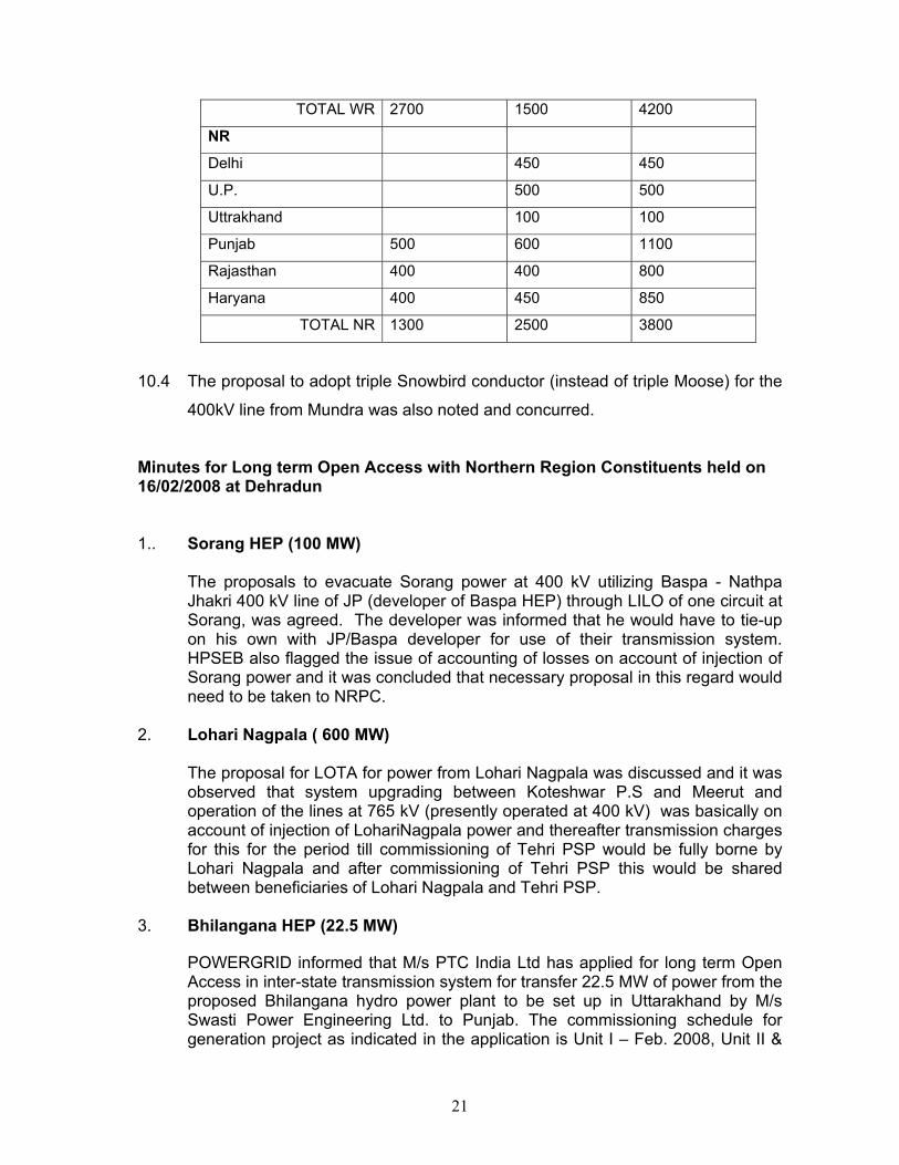
10.3 Power allocation from Mundra, Sasan and Krishnapatnam UMPPs
Mundra Sasan Total
Sasan+Mundra
WR
M.P. 1500 1500
Chattisgarh
Gujrat 1900 1900
Maharashtra 800 800
21
TOTAL WR 2700 1500 4200
NR
Delhi 450 450
U.P. 500 500
Uttrakhand 100 100
Punjab 500 600 1100
Rajasthan 400 400 800
Haryana 400 450 850
TOTAL NR 1300 2500 3800
10.4 The proposal to adopt triple Snowbird conductor (instead of triple Moose) for the
400kV line from Mundra was also noted and concurred.
Minutes for Long term Open Access with Northern Region Constituents held on 16/02/2008 at Dehradun 1.. Sorang HEP (100 MW)
The proposals to evacuate Sorang power at 400 kV utilizing Baspa - Nathpa Jhakri 400 kV line of JP (developer of Baspa HEP) through LILO of one circuit at Sorang, was agreed. The developer was informed that he would have to tie-up on his own with JP/Baspa developer for use of their transmission system. HPSEB also flagged the issue of accounting of losses on account of injection of Sorang power and it was concluded that necessary proposal in this regard would need to be taken to NRPC.
2. Lohari Nagpala ( 600 MW)
The proposal for LOTA for power from Lohari Nagpala was discussed and it was observed that system upgrading between Koteshwar P.S and Meerut and operation of the lines at 765 kV (presently operated at 400 kV) was basically on account of injection of LohariNagpala power and thereafter transmission charges for this for the period till commissioning of Tehri PSP would be fully borne by Lohari Nagpala and after commissioning of Tehri PSP this would be shared between beneficiaries of Lohari Nagpala and Tehri PSP.
3. Bhilangana HEP (22.5 MW)
POWERGRID informed that M/s PTC India Ltd has applied for long term Open Access in inter-state transmission system for transfer 22.5 MW of power from the proposed Bhilangana hydro power plant to be set up in Uttarakhand by M/s Swasti Power Engineering Ltd. to Punjab. The commissioning schedule for generation project as indicated in the application is Unit I – Feb. 2008, Unit II &

22
III – March 2008.The power would be injected at nearest substation of STU at 66kV and would be transferred to Punjab through displacement of part of share of Uttarakhand from generation projects like Singrauli, Rihand, Tehri, Dhauliganga etc. PTCUL informed that power from the Bhilangana project is to be injected at Ghansali substation at 33 kV level which has already been informed to the developers of the project. It was also informed that PTCUL has planned to establish a 220 kV substation at Ghansali and there would not be any constraint in transfer of power.
4. Open access for thermal projects in ER
POWERGRID informed that application for interional transfer of power for six generation projects (ER-Farakka-III, Chitrapur, KVK, WR-Lanco, JSW Energy, SR- Nagarjuna power) had been received. About 1320 MW of power is to be transferred to Northern Region from these projects. It was discussed that there was a constraint in the east-west corridor of Northern Region and therefore long term open access for transfer of power from the thermal projects in ER to NR could be granted only after commissioning of Balia- Bhiwadi HVDC line. However, connectivity of these projects could be allowed and till commissioning of Balia - Bhiwadi lines these would seek transmission through STOA.
5. Dadri SEZ of Reliance
It was noted that apart from seeking open access for CTU systems, the developer has also sought open access from Haryana which he had not informed to CTU. As the open access and related transmission planning was required to be done in a comprehensive manner, it was decided that the proposal needs a review and reconsideration in the next meeting.
6. Tapovan Vishnugad POWERGRID informed that M/s PTC India Ltd has applied for long term Open Access in inter-state transmission system for transfer 514 MW (520 MW less APC @1.2 %) including 61.7MW free power to Uttaranchal. PTCUL informed that the poling point as per agreement is Kashipur and system needs to be evolved from Kashipur. Constituents agreed that Generator needs to hold discussion with PTCUL and inform the pooling station from where open Access is to be considered.