standards of design and construction line standards/standards of desig… · - 2 - standards of...
TRANSCRIPT

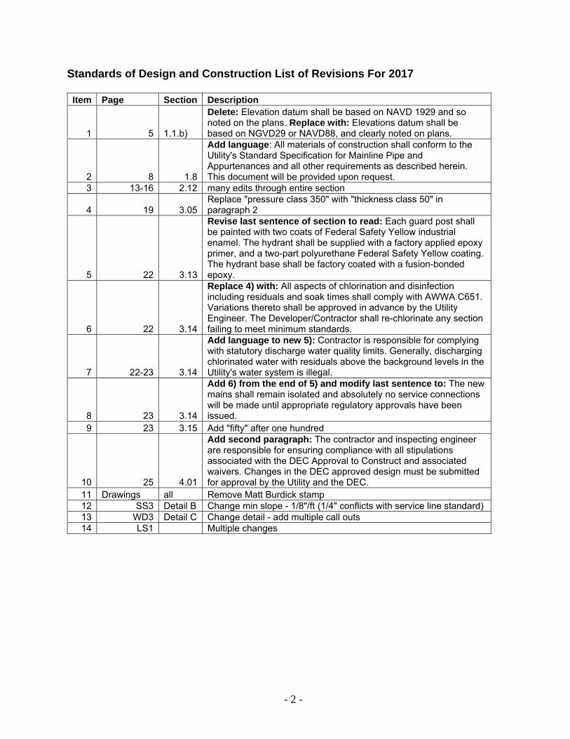
STANDARDS OF DESIGN AND CONSTRUCTION
Revised: April 2017
3691 Cameron Street Suite 201 P.O. Box 80370
Fairbanks, AK 99708 (907) 479-3118
www.akwater.com
- 2 -
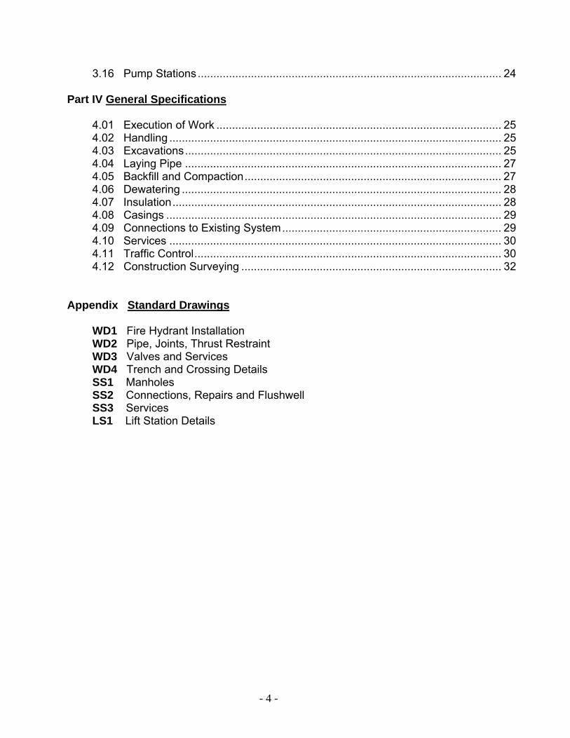
Standards of Design and Construction List of Revisions For 2017
Item Page Section Description
1 5 1.1.b)
Delete: Elevation datum shall be based on NAVD 1929 and so noted on the plans. Replace with: Elevations datum shall be based on NGVD29 or NAVD88, and clearly noted on plans.
2 8 1.8
Add language: All materials of construction shall conform to the Utility's Standard Specification for Mainline Pipe and Appurtenances and all other requirements as described herein. This document will be provided upon request.
3 13-16 2.12 many edits through entire section
4 19 3.05 Replace "pressure class 350" with "thickness class 50" in paragraph 2
5 22 3.13
Revise last sentence of section to read: Each guard post shall be painted with two coats of Federal Safety Yellow industrial enamel. The hydrant shall be supplied with a factory applied epoxy primer, and a two-part polyurethane Federal Safety Yellow coating. The hydrant base shall be factory coated with a fusion-bonded epoxy.
6 22 3.14
Replace 4) with: All aspects of chlorination and disinfection including residuals and soak times shall comply with AWWA C651. Variations thereto shall be approved in advance by the Utility Engineer. The Developer/Contractor shall re-chlorinate any section failing to meet minimum standards.
7 22-23 3.14
Add language to new 5): Contractor is responsible for complying with statutory discharge water quality limits. Generally, discharging chlorinated water with residuals above the background levels in the Utility's water system is illegal.
8 23 3.14
Add 6) from the end of 5) and modify last sentence to: The new mains shall remain isolated and absolutely no service connections will be made until appropriate regulatory approvals have been issued.
9 23 3.15 Add "fifty" after one hundred
10 25 4.01
Add second paragraph: The contractor and inspecting engineer are responsible for ensuring compliance with all stipulations associated with the DEC Approval to Construct and associated waivers. Changes in the DEC approved design must be submitted for approval by the Utility and the DEC.
11 Drawings all Remove Matt Burdick stamp 12 SS3 Detail B Change min slope - 1/8"/ft (1/4" conflicts with service line standard) 13 WD3 Detail C Change detail - add multiple call outs 14 LS1 Multiple changes

- 3 -
TABLE OF CONTENTS Part I General Design Requirements
1.1 Plan Submittal ................................................................................................. 5 1.2 Engineer’s Report ............................................................................................ 6 1.3 Engineer’s Responsibility ................................................................................ 6 1.4 Inspection of Work by the Utility ...................................................................... 7 1.5 Record Drawings ............................................................................................. 7 1.6 Separation Distance ........................................................................................ 8 1.7 Easements ...................................................................................................... 8 1.8 Materials .......................................................................................................... 8
Part II Design and Constriction of Wastewater Facilities
2.01 General ............................................................................................................ 9 2.02 Sizing ............................................................................................................... 9 2.03 Storm Water ..................................................................................................... 9 2.04 Design Flow ..................................................................................................... 9 2.05 Peaking Factor ................................................................................................. 9 2.06 Slope .............................................................................................................. 10 2.07 Size and Type of Pipe .................................................................................... 10 2.08 Depth of Cover ............................................................................................... 11 2.09 Final Accuracy ................................................................................................ 11 2.10 Manholes ........................................................................................................ 11 2.11 Flushwells ...................................................................................................... 12 2.12 Lift Stations .................................................................................................... 13 2.13 Acceptance Testing ........................................................................................ 16 2.14 Force Mains ................................................................................................... 17
Part III Design and Construction of Water Facilities
3.01 General ........................................................................................................... 18 3.02 Water System Hydraulics ................................................................................ 18 3.03 Design Capacity .............................................................................................. 18 3.04 System Pressure ............................................................................................. 19 3.05 Size & Type of Pipe ......................................................................................... 19 3.06 Depth of Cover ................................................................................................ 19 3.07 Water Main Placement .................................................................................... 19 3.08 Pipe Joints ....................................................................................................... 19 3.09 Restrained Joints ............................................................................................. 20 3.10 Pipe Fittings .................................................................................................... 20 3.11 Valves ............................................................................................................. 20 3.12 Valve Boxes .................................................................................................... 21 3.13 Fire Hydrants ................................................................................................... 21 3.14 Disinfection and Flushing ............................................................................... 22 3.15 Pressure Testing ............................................................................................. 23
- 4 -
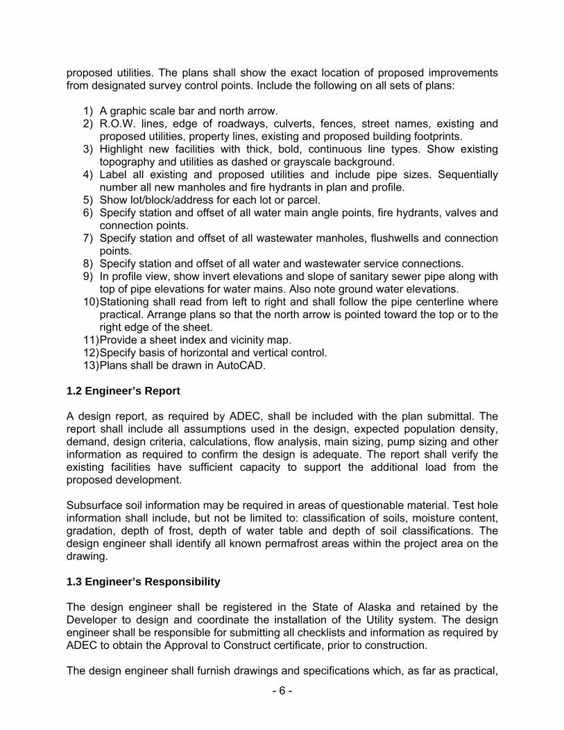
3.16 Pump Stations ................................................................................................. 24
Part IV General Specifications
4.01 Execution of Work ........................................................................................... 25 4.02 Handling .......................................................................................................... 25 4.03 Excavations ..................................................................................................... 25 4.04 Laying Pipe ..................................................................................................... 27 4.05 Backfill and Compaction .................................................................................. 27 4.06 Dewatering ...................................................................................................... 28 4.07 Insulation ......................................................................................................... 28 4.08 Casings ........................................................................................................... 29 4.09 Connections to Existing System ...................................................................... 29 4.10 Services .......................................................................................................... 30 4.11 Traffic Control .................................................................................................. 30 4.12 Construction Surveying ................................................................................... 32
Appendix Standard Drawings
WD1 Fire Hydrant Installation WD2 Pipe, Joints, Thrust Restraint WD3 Valves and Services WD4 Trench and Crossing Details SS1 Manholes SS2 Connections, Repairs and Flushwell SS3 Services LS1 Lift Station Details

- 5 -
PART I GENERAL DESIGN REQUIREMENTS The design of a water distribution or wastewater collection system within the Golden Heart Utilities or the College Utilities Corporation (hereinafter referred to as the Utility) service area shall be submitted to and approved by the Alaska Department of Environmental Conservation (ADEC) and the Utility prior to construction. The design shall be in accordance with: State Regulations (specifically 18 AAC 72 for wastewater and 18 AAC 80 for water), the current Uniform Plumbing Code, Uniform Fire Code, the standards of American National Standards Institute (ANSI), American Water Works Association (AWWA), American Society for Testing and Materials (ASTM), Utility master plans and these Standards of Design and Construction. Final design shall be certified by a professional engineer registered in the State of Alaska. A preliminary concept design shall be submitted to the Utility prior to the preparation of the final design. The purpose of the submittal is to present the preliminary lay-out, controlling assumptions and considerations used for the planning of the proposed system with emphasis on impacts to the existing system. The proposed final plat of the improvement area shall be submitted with each design. Any addition to the Utility water or wastewater system shall be consistent with the Utility’s standards of design and quality of materials and construction. Emphasis shall be given to reduce future operation and maintenance costs. Design details shall be conducive to minimizing potential freezing problems. Special consideration shall be given to cold temperatures, permafrost and high water tables; conditions common in Fairbanks. Allowances for future extensions will be made in the design of all additions. This document is designed to aid in meeting the requirements of the Utility. It must be emphasized that no single document can possibly present guidelines for all situations that will be encountered. The Utility shall have the ultimate authority to interpret this document and may direct modifications for specific situations. 1.1 Plan Submittal a) Standard Sheets and Scales The standard plan sheet size shall be 11” x 17”. Standard scale shall be one (1) inch equals forty (40) feet (1” = 40’) horizontal and one (1) inch equals four (4) feet (1” = 4’) vertical. Plan sheet sizes up to 24” x 36” will be acceptable with a maximum horizontal scale of one (1) inch equals fifty (50) feet (1” = 50’), when plotted on 24” x 36”. b) Elevation Datum Elevations datum shall be based on NGVD29 or NAVD88, and clearly noted on plans. c) Plan and Profile Information Standard plan and profile sheets shall be used and shall depict all existing and
- 6 -
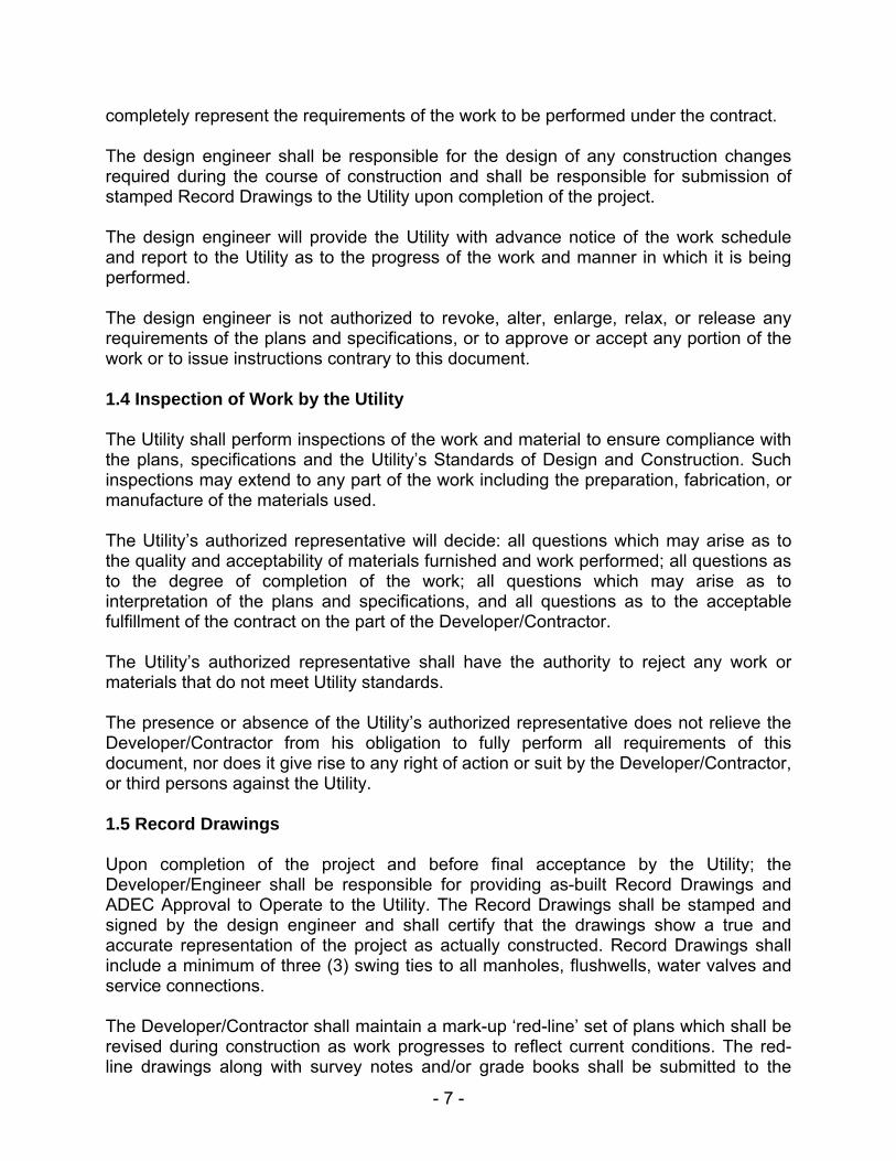
proposed utilities. The plans shall show the exact location of proposed improvements from designated survey control points. Include the following on all sets of plans:
1) A graphic scale bar and north arrow. 2) R.O.W. lines, edge of roadways, culverts, fences, street names, existing and
proposed utilities, property lines, existing and proposed building footprints. 3) Highlight new facilities with thick, bold, continuous line types. Show existing
topography and utilities as dashed or grayscale background. 4) Label all existing and proposed utilities and include pipe sizes. Sequentially
number all new manholes and fire hydrants in plan and profile. 5) Show lot/block/address for each lot or parcel. 6) Specify station and offset of all water main angle points, fire hydrants, valves and
connection points. 7) Specify station and offset of all wastewater manholes, flushwells and connection
points. 8) Specify station and offset of all water and wastewater service connections. 9) In profile view, show invert elevations and slope of sanitary sewer pipe along with
top of pipe elevations for water mains. Also note ground water elevations. 10) Stationing shall read from left to right and shall follow the pipe centerline where
practical. Arrange plans so that the north arrow is pointed toward the top or to the right edge of the sheet.
11) Provide a sheet index and vicinity map. 12) Specify basis of horizontal and vertical control. 13) Plans shall be drawn in AutoCAD.
1.2 Engineer’s Report
A design report, as required by ADEC, shall be included with the plan submittal. The report shall include all assumptions used in the design, expected population density, demand, design criteria, calculations, flow analysis, main sizing, pump sizing and other information as required to confirm the design is adequate. The report shall verify the existing facilities have sufficient capacity to support the additional load from the proposed development. Subsurface soil information may be required in areas of questionable material. Test hole information shall include, but not be limited to: classification of soils, moisture content, gradation, depth of frost, depth of water table and depth of soil classifications. The design engineer shall identify all known permafrost areas within the project area on the drawing. 1.3 Engineer’s Responsibility The design engineer shall be registered in the State of Alaska and retained by the Developer to design and coordinate the installation of the Utility system. The design engineer shall be responsible for submitting all checklists and information as required by ADEC to obtain the Approval to Construct certificate, prior to construction. The design engineer shall furnish drawings and specifications which, as far as practical,
- 7 -
completely represent the requirements of the work to be performed under the contract.
The design engineer shall be responsible for the design of any construction changes required during the course of construction and shall be responsible for submission of stamped Record Drawings to the Utility upon completion of the project. The design engineer will provide the Utility with advance notice of the work schedule and report to the Utility as to the progress of the work and manner in which it is being performed.
The design engineer is not authorized to revoke, alter, enlarge, relax, or release any requirements of the plans and specifications, or to approve or accept any portion of the work or to issue instructions contrary to this document.
1.4 Inspection of Work by the Utility The Utility shall perform inspections of the work and material to ensure compliance with the plans, specifications and the Utility’s Standards of Design and Construction. Such inspections may extend to any part of the work including the preparation, fabrication, or manufacture of the materials used.
The Utility’s authorized representative will decide: all questions which may arise as to the quality and acceptability of materials furnished and work performed; all questions as to the degree of completion of the work; all questions which may arise as to interpretation of the plans and specifications, and all questions as to the acceptable fulfillment of the contract on the part of the Developer/Contractor.
The Utility’s authorized representative shall have the authority to reject any work or materials that do not meet Utility standards.
The presence or absence of the Utility’s authorized representative does not relieve the Developer/Contractor from his obligation to fully perform all requirements of this document, nor does it give rise to any right of action or suit by the Developer/Contractor, or third persons against the Utility. 1.5 Record Drawings Upon completion of the project and before final acceptance by the Utility; the Developer/Engineer shall be responsible for providing as-built Record Drawings and ADEC Approval to Operate to the Utility. The Record Drawings shall be stamped and signed by the design engineer and shall certify that the drawings show a true and accurate representation of the project as actually constructed. Record Drawings shall include a minimum of three (3) swing ties to all manholes, flushwells, water valves and service connections. The Developer/Contractor shall maintain a mark-up ‘red-line’ set of plans which shall be revised during construction as work progresses to reflect current conditions. The red-line drawings along with survey notes and/or grade books shall be submitted to the

- 8 -
design engineer for as-built preparation. The revisions are to be indicated in a neat, well organized manner and are to include the elevation and plan location of any utilities, structures, etc. encountered or installed. Two (2) paper copies and one (1) electronic AutoCAD copy of the Record Drawings shall be submitted to the Utility. The Utility will stamp one (1) set (as the inspecting engineer of record) and submit to ADEC for the Approval to Operate certificate, however, the Developer/Contractor shall be ultimately responsible for obtaining the ADEC Approval to Operate. Time Limit for Record Drawing Submittal - Final acceptance of the development will not occur until the Record Drawings have been approved by the Utility, and all obligations under the Utility’s Developer Agreement have been satisfied. The system improvements shall not be available for customer use until Record Drawings have been approved and meet the requirements of ADEC Regulations 18 AAC 72 and 18 AAC 80. 1.6 Separation Distance Water and wastewater mains (including manholes) shall be separated by a minimum of ten (10) feet horizontally measured edge to edge. Where it is not possible to maintain a ten (10) foot separation, a waiver request must be submitted to ADEC. For purposes of separation, storm drain sewers are considered equivalent to sanitary sewers. Where water/wastewater mains must cross, the water main shall be above the wastewater main, and a minimum of eighteen (18) inches vertical separation shall be provided. The crossing shall be arranged so that a full length of pipe will be centered on the crossing and the water line joints are at least nine (9) feet from the wastewater line. Where this is not possible; a waiver request must be submitted to ADEC. All other existing and proposed utilities, (electric, phone, gas, cable, etc.), shall be separated by a minimum of five (5) feet horizontally from Utility water or wastewater facilities. Placement of utilities shall be consistent with State or local R.O.W. guidelines. 1.7 Easements For maintenance access, permanent easements are required for Utility mains constructed on private property. Easements shall be a minimum of twenty (20) feet wide for a single utility pipeline and a minimum of thirty (30) feet wide for pipes deeper than fifteen (15) feet. For multiple lines, water and wastewater easements shall provide a minimum of ten (10) feet clearance on either side of each pipe. 1.8 Materials All materials of construction shall conform to the most current version of the Utility’s Standard Specification for Mainline Pipe and Appurtenances and all other requirements as described herein. This document will be provided upon request.

- 9 -
PART II DESIGN AND CONSTRUCTION OF WASTEWATER FACILITIES 2.01 General Sewage must be transported in a sanitary manner through the Utility wastewater collection system with an absolute minimum of infiltration of groundwater and in-flow of storm runoff. Attention shall be given to design details which will minimize potential freezing problems within the wastewater collection system. Wastewater mains shall be located in the street R.O.W. to facilitate maintenance. Special consideration should be given to cold temperatures, permafrost, and high water tables. Gravity flow is usually most desirable, but in some cases pumping may be required.
2.02 Sizing Sanitary sewer mains shall be sized for the ultimate population and/or land use that can reasonably be expected to develop in the tributary area within a period of fifty (50) years. The following factors shall be considered when determining sanitary sewer sizing:
1) Maximum hourly domestic sewage flow 2) Additional maximum flow from industrial or commercial sources 3) Inflow and ground water infiltration 4) Topography of area 5) Location of nearest existing sewer main which can accept the flow 6) Depth of excavation 7) Pumping requirements
2.03 Storm Water Under no conditions shall storm drain or roof drain connections be allowed to connect to the Utility wastewater collection system (GHU/CUC Tariff section 6.4). 2.04 Design Flow Basic design capacity shall be based on the peak hourly flow. For typical domestic situations, an average daily per capita flow of one hundred (100) gallons per day shall be used along with an assumption of three point five (3.5) persons per residential dwelling unit. Various sources are available to estimate commercial, industrial, and inflow/infiltration flows; which will be examined on a case by case basis. 2.05 Peaking Factors Peaking factors are inversely proportional to the average daily flow in a pipe. Peaking

- 10 -
factors for very small flows can be substantially higher than for larger flows. The following table is provided as a guide to calculate peak flow conditions:
AVERAGE DAILY FLOW(GALLONS)
PEAKING FACTOR
1,000 or less 150 3,000 55
30,000 8 100,000 3.4 300,000 2.5
1,000,000 and more 2.0 Factors for flow other than these may be extrapolated. A minimum peak design flow of one hundred (100) gallons per minute shall be used for any new sanitary sewer. 2.06 Slope The slope of a gravity sanitary sewer is important to maintain a self-cleansing velocity, generally recommended at two (2) feet per second (fps), when flowing full. It is usual practice to design for this velocity at peak design flows, recognizing that prior to ultimate development some deposits will occur and more frequent cleaning will be required. Slopes shall be uniform between manholes. The following table lists the minimum slopes for various pipe sizes and full flow capacity:
SIZE (inch)
SLOPE (ft/ft)
CAPACITY(gpm)
8 0.0033 370 10 0.0028 560 12 0.0022 800 14 0.0017 1,075 16 0.0014 1,390 18 0.0012 1,755 20 0.0011 2,125 24 0.0008 3,090 30 0.00058 4,850 36 0.00046 7,200
Wastewater Utility mains shall be laid at minimum slope. Grades may be set slightly higher in locations where no further development is expected and lack of cover is not an issue. The Utility will review each case individually. 2.07 Size and Type of Pipe Gravity wastewater mains shall not be less than eight (8) inch diameter. Force main (pumped) sewer mains shall not be less than four (4) inch diameter. Gravity wastewater and force main sewer pipe shall be cement mortar lined ductile iron

- 11 -
pipe (min. pressure class); conforming to AWWA C151 and C104. Joints shall be rubber gasketed push on Tyton ®. The Utility may consider the use of HDPE (SDR 17) for force main sewers on an individual basis. Service piping shall be ductile iron or HDPE and shall not be less than four (4) inch diameter. 2.08 Depth of Cover Wastewater mains shall be sufficiently deep to receive sewage from basements and to prevent freezing. Wastewater mains shall have a minimum depth of cover of five (5) feet. 2.09 Final Accuracy At any point during construction, including prior to backfilling, the Utility may require the Developer/Contractor to provide verification that the pipes or other Utility structures are set to the proper grade. Final accuracy of all gravity sanitary sewer main installations shall be within one-hundredths (1/100) of a foot vertically and one-half (1/2) of a foot horizontally of the exact location taken from the project plans. In addition, no single section of pipe shall vary by more than ten (10) percent from the grade shown on the project plans. In no case will a reverse or flat grade be allowed. Pipe which exceeds the above limits of variation shall be adjusted immediately and no further pipe shall be laid until so authorized by the Utility. All costs incurred for adjusting grades of lines shall be the responsibility of the Developer/Contractor. 2.10 Manholes All intersections or changes in direction of gravity flow shall be in manholes which shall be designed to minimize deposition and aid in maintenance and inspection. Inflow pipes shall have smooth transitional grading in flow channels to minimize the effects of drops. Match crown elevations when joining pipes of different sizes. On a straight section, the grade of the manhole channel shall be the same as the pipes entering and exiting. A section of pipe (with the top half cut out) will pass completely through the manhole. Where there is a change of horizontal direction, the drop through the manhole shall be a minimum of one-tenth (1/10) of a foot. Service connections to manholes will be allowed only with Utility permission. Manhole placement shall typically be within the street intersections. Avoid placing manhole lids in vehicle tire paths. Distances between manholes shall not exceed three hundred (300) feet. The manhole inside diameter shall be forty-eight (48) inches. Two (2) manholes shall be placed adjacent to lift stations; one upstream, one downstream, to facilitate bypassing operations. All dead end mains shall terminate with a manhole or an eight (8) inch diameter flushwell.
- 12 -
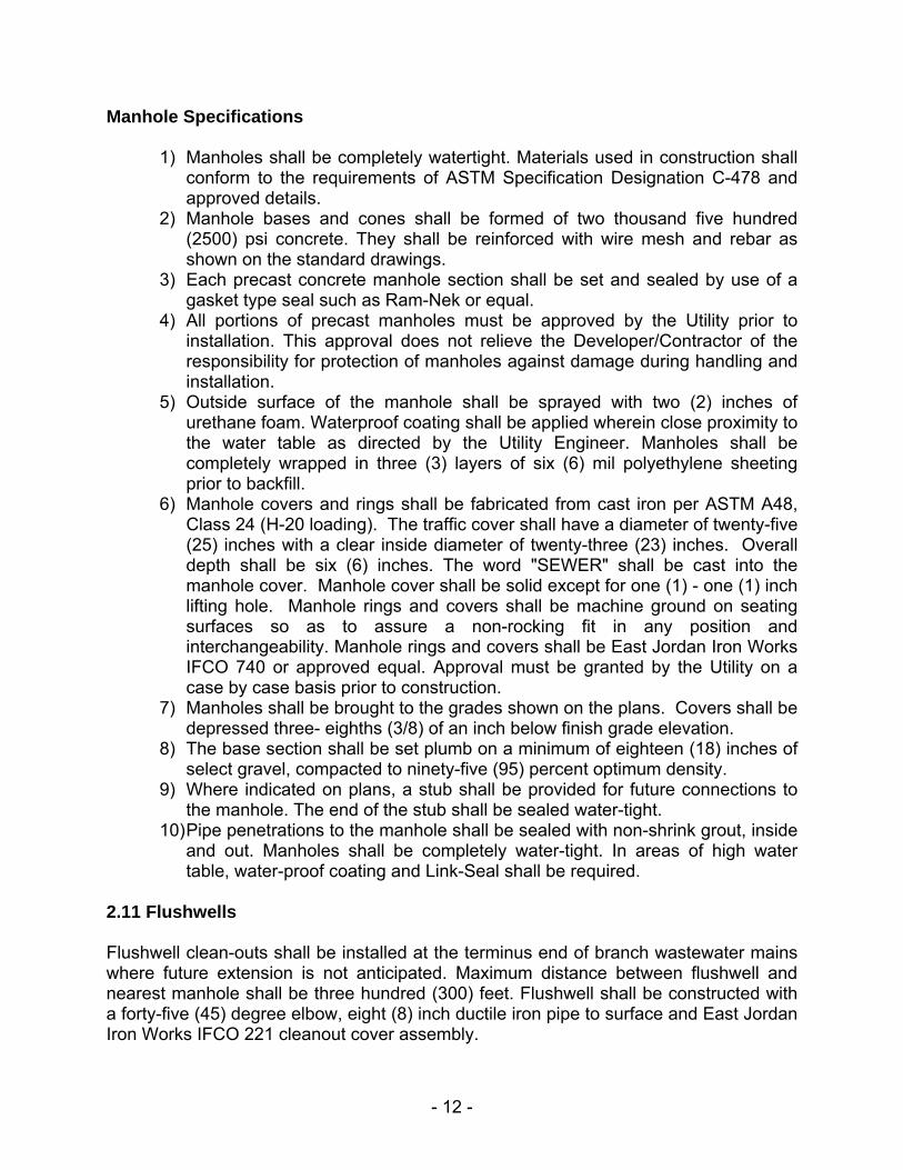
Manhole Specifications
1) Manholes shall be completely watertight. Materials used in construction shall conform to the requirements of ASTM Specification Designation C-478 and approved details.
2) Manhole bases and cones shall be formed of two thousand five hundred (2500) psi concrete. They shall be reinforced with wire mesh and rebar as shown on the standard drawings.
3) Each precast concrete manhole section shall be set and sealed by use of a gasket type seal such as Ram-Nek or equal.
4) All portions of precast manholes must be approved by the Utility prior to installation. This approval does not relieve the Developer/Contractor of the responsibility for protection of manholes against damage during handling and installation.
5) Outside surface of the manhole shall be sprayed with two (2) inches of urethane foam. Waterproof coating shall be applied wherein close proximity to the water table as directed by the Utility Engineer. Manholes shall be completely wrapped in three (3) layers of six (6) mil polyethylene sheeting prior to backfill.
6) Manhole covers and rings shall be fabricated from cast iron per ASTM A48, Class 24 (H-20 loading). The traffic cover shall have a diameter of twenty-five (25) inches with a clear inside diameter of twenty-three (23) inches. Overall depth shall be six (6) inches. The word "SEWER" shall be cast into the manhole cover. Manhole cover shall be solid except for one (1) - one (1) inch lifting hole. Manhole rings and covers shall be machine ground on seating surfaces so as to assure a non-rocking fit in any position and interchangeability. Manhole rings and covers shall be East Jordan Iron Works IFCO 740 or approved equal. Approval must be granted by the Utility on a case by case basis prior to construction.
7) Manholes shall be brought to the grades shown on the plans. Covers shall be depressed three- eighths (3/8) of an inch below finish grade elevation.
8) The base section shall be set plumb on a minimum of eighteen (18) inches of select gravel, compacted to ninety-five (95) percent optimum density.
9) Where indicated on plans, a stub shall be provided for future connections to the manhole. The end of the stub shall be sealed water-tight.
10) Pipe penetrations to the manhole shall be sealed with non-shrink grout, inside and out. Manholes shall be completely water-tight. In areas of high water table, water-proof coating and Link-Seal shall be required.
2.11 Flushwells Flushwell clean-outs shall be installed at the terminus end of branch wastewater mains where future extension is not anticipated. Maximum distance between flushwell and nearest manhole shall be three hundred (300) feet. Flushwell shall be constructed with a forty-five (45) degree elbow, eight (8) inch ductile iron pipe to surface and East Jordan Iron Works IFCO 221 cleanout cover assembly.

- 13 -
2.12 Lift Stations a) General The combination of flat topography, deep frost penetration, high water table and high construction costs for excavation often make sewer lift stations necessary. Where existing gravity sewer mains cannot be extended to service an area, a central receiving lift station is installed and the discharge is pumped to the nearest gravity collection point. Since lift stations are expensive to construct and to operate, they shall be utilized only as absolutely necessary, and be consistent with Utility planning. Lift stations shall be installed as deep as practically possible in order to serve foreseeable future development and to keep the number of lift stations to a minimum. The information in this Standard is intended to provide general information regarding the typical configuration of a Utility lift station. Due to variable site conditions, the methods and materials of construction for individual lift stations may vary. The Utility’s requirements for lift station construction may vary accordingly to ensure ease of maintenance and long life. The Developer is responsible for all associated costs for construction and commissioning. As required to meet Utility requirements. The Engineer’s design report shall include present and ultimate design information including: pump curves, system curve, estimated operating point (gpm/head), impeller size, area to be served, pump run time, pump cycle time, anticipated power consumption, operations and maintenance information, recommended spare parts, and other appropriate information. b) Pumps Lift stations shall be designed with a reinforced concrete receiving well and furnished with a minimum of two (2) heavy duty, submersible, non-clog wastewater pumps. Each pump shall be capable of handling peak design flow. The system will be completely automatic and electrical controls and accessories shall be completely compatible with the pumps. Pumps shall be Flygt, type NP, 7.5 minimum horsepower. Bases, relay, check valves, guide rail, seal leakage detection and hatches shall all be manufactured by Flygt. c) Safety The lift station site shall be readily accessible but outside of street driving surfaces. Safety shall be a primary concern in designing access within the lift station. All electrical equipment and devices within the lift station shall be rated for use in Class I, Division 1 hazardous locations (per NEC/NFPA 70). Each lift station shall be vented. Heavy duty access covers shall be designed for H-20 traffic loads and shall feature Safe-Hatch fall through protection grating. d) Capacity Capacity of the lift station shall be based on the peak hourly flow (average daily flow
- 14 -
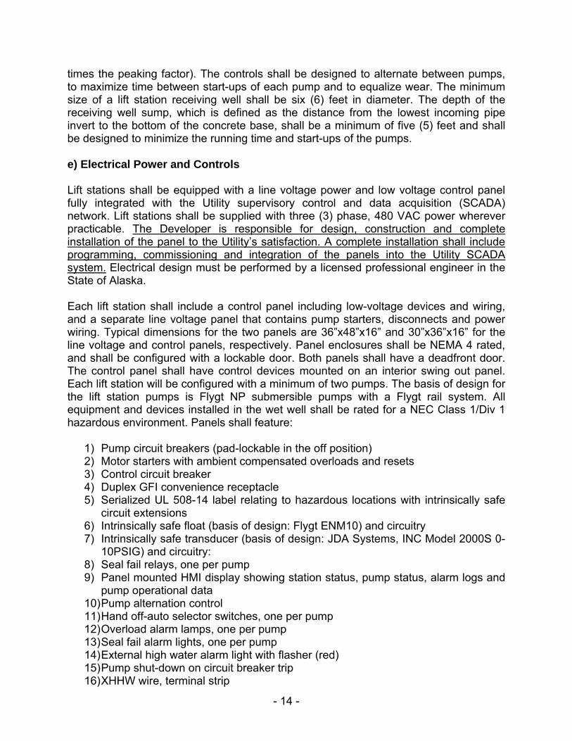
times the peaking factor). The controls shall be designed to alternate between pumps, to maximize time between start-ups of each pump and to equalize wear. The minimum size of a lift station receiving well shall be six (6) feet in diameter. The depth of the receiving well sump, which is defined as the distance from the lowest incoming pipe invert to the bottom of the concrete base, shall be a minimum of five (5) feet and shall be designed to minimize the running time and start-ups of the pumps. e) Electrical Power and Controls Lift stations shall be equipped with a line voltage power and low voltage control panel fully integrated with the Utility supervisory control and data acquisition (SCADA) network. Lift stations shall be supplied with three (3) phase, 480 VAC power wherever practicable. The Developer is responsible for design, construction and complete installation of the panel to the Utility’s satisfaction. A complete installation shall include programming, commissioning and integration of the panels into the Utility SCADA system. Electrical design must be performed by a licensed professional engineer in the State of Alaska. Each lift station shall include a control panel including low-voltage devices and wiring, and a separate line voltage panel that contains pump starters, disconnects and power wiring. Typical dimensions for the two panels are 36”x48”x16” and 30”x36”x16” for the line voltage and control panels, respectively. Panel enclosures shall be NEMA 4 rated, and shall be configured with a lockable door. Both panels shall have a deadfront door. The control panel shall have control devices mounted on an interior swing out panel. Each lift station will be configured with a minimum of two pumps. The basis of design for the lift station pumps is Flygt NP submersible pumps with a Flygt rail system. All equipment and devices installed in the wet well shall be rated for a NEC Class 1/Div 1 hazardous environment. Panels shall feature:
1) Pump circuit breakers (pad-lockable in the off position) 2) Motor starters with ambient compensated overloads and resets 3) Control circuit breaker 4) Duplex GFI convenience receptacle 5) Serialized UL 508-14 label relating to hazardous locations with intrinsically safe
circuit extensions 6) Intrinsically safe float (basis of design: Flygt ENM10) and circuitry 7) Intrinsically safe transducer (basis of design: JDA Systems, INC Model 2000S 0-
10PSIG) and circuitry: 8) Seal fail relays, one per pump 9) Panel mounted HMI display showing station status, pump status, alarm logs and
pump operational data 10) Pump alternation control 11) Hand off-auto selector switches, one per pump 12) Overload alarm lamps, one per pump 13) Seal fail alarm lights, one per pump 14) External high water alarm light with flasher (red) 15) Pump shut-down on circuit breaker trip 16) XHHW wire, terminal strip
- 15 -
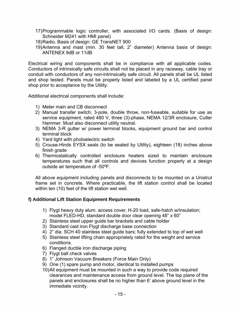
17) Programmable logic controller, with associated I/O cards. (Basis of design: Schneider M241 with HMI panel)
18) Radio. Basis of design: GE TransNET 900 19) Antenna and mast (min. 30 feet tall, 2” diameter) Antenna basis of design:
ANTENEX 9dB or 11dB Electrical wiring and components shall be in compliance with all applicable codes. Conductors of intrinsically safe circuits shall not be placed in any raceway, cable tray or conduit with conductors of any non-intrinsically safe circuit. All panels shall be UL listed and shop tested. Panels must be properly listed and labeled by a UL certified panel shop prior to acceptance by the Utility. Additional electrical components shall include:
1) Meter main and CB disconnect 2) Manual transfer switch, 3-pole, double throw, non-fuseable, suitable for use as
service equipment, rated 480 V, three (3)-phase, NEMA 12/3R enclosure, Cutler Hammer. Must also disconnect utility neutral.
3) NEMA 3-R gutter w/ power terminal blocks, equipment ground bar and control terminal block
4) Yard light with photoelectric switch 5) Crouse-Hinds EYSX seals (to be sealed by Utility), eighteen (18) inches above
finish grade 6) Thermostatically controlled enclosure heaters sized to maintain enclosure
temperatures such that all controls and devices function properly at a design outside air temperature of -50⁰F.
All above equipment including panels and disconnects to be mounted on a Unistrut frame set in concrete. Where practicable, the lift station control shall be located within ten (10) feet of the lift station wet well.
f) Additional Lift Station Equipment Requirements
1) Flygt heavy duty alum. access cover, H-20 load, safe-hatch w/insulation; model FLED-HD, standard double door clear opening 48” x 60”
2) Stainless steel upper guide bar brackets and cable holder 3) Standard cast iron Flygt discharge base connection 4) 2” dia. SCH 40 stainless steel guide bars; fully extended to top of wet well 5) Stainless steel lifting chain appropriately rated for the weight and service
conditions. 6) Flanged ductile iron discharge piping 7) Flygt ball check valves 8) 1” Johnson Vacuum Breakers (Force Main Only) 9) One (1) spare pump and motor, identical to installed pumps 10) All equipment must be mounted in such a way to provide code required
clearances and maintenance access from ground level. The top plane of the panels and enclosures shall be no higher than 6’ above ground level in the immediate vicinity.

- 16 -
11) The lift station must be readily accessible by Utility personnel and heavy vehicles to facilitate ongoing maintenance.
12) Complete electrical drawings and O&M manuals. Drawings shall be provided in AutoCAD and PDF format. O&M manual shall include part numbers and vendors of all devices. Developer is responsible for demonstrating to the Utility’s satisfaction that the lift station controls, mechanical equipment and remote communications are fully functional and capable of supporting fully automatic operation prior to acceptance.
2.13 Acceptance Testing a) Pressure Testing All gravity wastewater mains shall be air tested in accordance with ASTM C 828 after services are installed. Test sections shall be isolated and initially pressurized to four (4) psig. After stabilization, reduce the pressure to three point five (3.5) psi before starting the test. If a one (1) psig drop does not occur within the test time, (Table 2.1), the line has passed. If the pressure drop is more than one (1) psig during the test time, the line is presumed to have failed the test. The Developer/Contractor shall make all necessary repairs until achieving a successful test.
Table 2.1 Minimum Test Time for Various Pipe Sizes
Nominal PipeSize (inch)
T (time) Minutes/100 ft
8 1.2 10 1.5 12 1.8 14 2.0 16 2.2 18 2.4 20 3.0 24 3.6 30 4.8
b) Cleaning When all installation work is complete, the Contractor shall remove debris from all pipe, manholes, wet wells etc. The mains and manholes shall be flushed with water to the satisfaction of the Utility. c) Video Inspection After the pipe has been cleaned and tested, the mains shall be video inspected. The video inspection shall be of a format and quality approved by the Utility. Video inspection work by any contractor, other than College Utilities, shall require prior
- 17 -
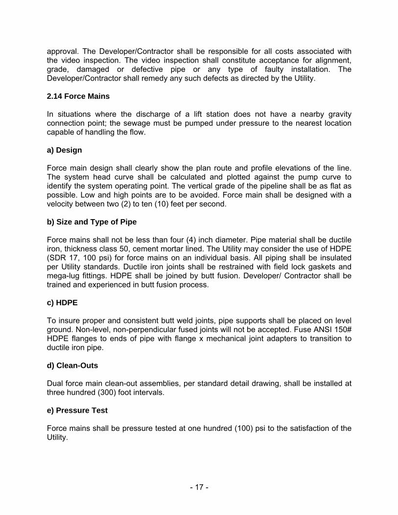
approval. The Developer/Contractor shall be responsible for all costs associated with the video inspection. The video inspection shall constitute acceptance for alignment, grade, damaged or defective pipe or any type of faulty installation. The Developer/Contractor shall remedy any such defects as directed by the Utility. 2.14 Force Mains In situations where the discharge of a lift station does not have a nearby gravity connection point; the sewage must be pumped under pressure to the nearest location capable of handling the flow. a) Design Force main design shall clearly show the plan route and profile elevations of the line. The system head curve shall be calculated and plotted against the pump curve to identify the system operating point. The vertical grade of the pipeline shall be as flat as possible. Low and high points are to be avoided. Force main shall be designed with a velocity between two (2) to ten (10) feet per second. b) Size and Type of Pipe Force mains shall not be less than four (4) inch diameter. Pipe material shall be ductile iron, thickness class 50, cement mortar lined. The Utility may consider the use of HDPE (SDR 17, 100 psi) for force mains on an individual basis. All piping shall be insulated per Utility standards. Ductile iron joints shall be restrained with field lock gaskets and mega-lug fittings. HDPE shall be joined by butt fusion. Developer/ Contractor shall be trained and experienced in butt fusion process. c) HDPE To insure proper and consistent butt weld joints, pipe supports shall be placed on level ground. Non-level, non-perpendicular fused joints will not be accepted. Fuse ANSI 150# HDPE flanges to ends of pipe with flange x mechanical joint adapters to transition to ductile iron pipe. d) Clean-Outs Dual force main clean-out assemblies, per standard detail drawing, shall be installed at three hundred (300) foot intervals. e) Pressure Test Force mains shall be pressure tested at one hundred (100) psi to the satisfaction of the Utility.

- 18 -
Part III DESIGN AND CONSTRUCTION OF WATER FACILITIES 3.01 General Designing additions or modifications to the Utility water distribution system can present problems not normally encountered in typical water system design. Permafrost and deep seasonal frost result in conditions where the distribution system must be circulated to prevent freezing. Special attention must be given to any addition or modification and its effect on existing flow patterns. Service connections, fire hydrant installation and valve operations all require special consideration in the Fairbanks environment. 3.02 Water System Hydraulics Any addition or change to the Utility water distribution system shall be designed to minimize the risk of freezing. Water lines shall be insulated with urethane foam and circulated by pump stations to prevent freezing. The distribution network shall be laid out in hydraulically balanced loops with no dead ends. A main velocity of approximately two (2) feet per second is required to prevent freezing. New additions to the system must be designed for this minimum flow and must not interfere with the balance of the existing distribution system. Additionally, new additions must supply sufficient flow and pressure to provide for both consumption and fire protection. In order to evaluate the hydraulics of the proposed addition or modification and to examine the impact it has on the existing system, the Developer/Contractor shall submit a preliminary layout of the proposed water system to the Utility. The Utility will then analyze the system using its water modeling software. The results will be used to confirm adequate flow and pressure in the new and existing system and to determine if a pumping station will be required. If a problem exists, the Utility will suggest possible solutions such as changing pipe sizes or piping layouts. The Developer/Contractor shall then resubmit preliminary designs until a workable solution is achieved. A copy of the final water model will be provided to the Developer/Contractor to be included in the report to ADEC. These guidelines shall also apply to water transmission lines except that system velocities may be reduced and service connections may be restricted. 3.03 Design Capacity Basic design capacity shall provide for peak demand or fire protection requirement, whichever is larger. Design water consumption for the Utility shall be one hundred (100) gallons per day per capita. Peak hourly demand for residential areas shall generally be at least four and one-half (4½) times the average daily demand. Capacity for commercial and industrial use will usually be based on the fire protection requirement. Actual fire protection requirements are based on ISO requirements and will be determined in conjunction with ISO to optimize the insurance rating for the entire service territory.

- 19 -
3.04 System Pressure Normal operating pressure of the Golden Heart Utilities water system is ninety-five (95) psi. Normal operating pressure of the College Utilities Corp. system is one hundred forty-five (145) psi. Design pressure for both systems shall be two hundred (200) psi. The connection of a fire booster pump to the Utility water system is prohibited without advance written approval.
3.05 Size and Type of Pipe All pipe and materials shall meet the requirements of the National Sanitation Foundation (NSF) 61. Water mains shall be ductile iron pipe, thickness class 50, cement mortar lined, push on Tyton® joint. Pipe shall conform to AWWA C151. Cement lining shall conform to AWWA C104. Minimum water main size shall be six (6) inch diameter. Water service piping shall be ductile iron, type K copper or standard wall steel. Copper tubing shall conform to ASTM B-88. Service sizes shall be three-quarters (3/4) of an inch, one (1) inch and one and one-half (1½) inch for copper. Services larger than one and one-half (1½) inch shall be ductile iron or steel. Design and construction requirements for services are outlined in a separate document, SERVICE LINE STANDARDS, which is available on our website at www.akwater.com. 3.06 Depth of Cover Water mains shall have a minimum depth of cover of four (4) feet. When cover on existing pipe is less than four (4) feet due to road excavation, ditches, etc., the existing water main shall be lowered or insulated, as directed by the Utility. 3.07 Water Main Placement Water mains shall be typically located parallel to and offset seven (7) feet into the dedicated R.O.W. and a minimum of five (5) feet from any other existing or proposed buried utility. 3.08 Pipe Joints Ductile iron joints shall be push-on Tyton®; conforming to AWWA C111. Joining plain end sections shall be with Romac® couplings or approved equal. Approval must be granted by the Utility on a case by case basis prior to construction. For services, copper tubing joints shall be flare type and steel pipe shall be plain end suitable for Romac couplings or welding. No threaded joints shall be used below ground.
- 20 -
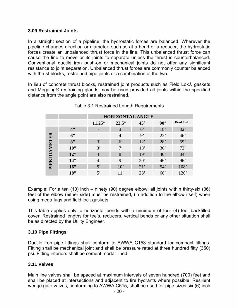
3.09 Restrained Joints In a straight section of a pipeline, the hydrostatic forces are balanced. Wherever the pipeline changes direction or diameter, such as at a bend or a reducer, the hydrostatic forces create an unbalanced thrust force in the line. This unbalanced thrust force can cause the line to move or its joints to separate unless the thrust is counterbalanced. Conventional ductile iron push-on or mechanical joints do not offer any significant resistance to joint separation. Unbalanced thrust forces are commonly counter balanced with thrust blocks, restrained pipe joints or a combination of the two. In lieu of concrete thrust blocks, restrained joint products such as Field Lok® gaskets and Megalug® restraining glands may be used provided all joints within the specified distance from the angle point are also restrained.
Table 3.1 Restrained Length Requirements
HORIZONTAL ANGLE 11.25° 22.5° 45° 90° Dead End
PIP
E D
IAM
ET
ER
4” - 3’ 6’ 18’ 32’ 6” - 4’ 9’ 22’ 46’ 8” 3’ 6’ 12’ 28’ 59’ 10” 3’ 7’ 18’ 36’ 72’ 12” 4’ 8’ 19’ 40’ 84’ 14” 4’ 9’ 20’ 46’ 96’ 16” 5’ 10’ 21’ 54’ 108’ 18” 5’ 11’ 23’ 60’ 120’
Example: For a ten (10) inch – ninety (90) degree elbow; all joints within thirty-six (36) feet of the elbow (either side) must be restrained, (in addition to the elbow itself) when using mega-lugs and field lock gaskets. This table applies only to horizontal bends with a minimum of four (4) feet backfilled cover. Restrained lengths for tee’s, reducers, vertical bends or any other situation shall be as directed by the Utility Engineer. 3.10 Pipe Fittings Ductile iron pipe fittings shall conform to AWWA C153 standard for compact fittings. Fitting shall be mechanical joint and shall be pressure rated at three hundred fifty (350) psi. Fitting interiors shall be cement mortar lined. 3.11 Valves Main line valves shall be spaced at maximum intervals of seven hundred (700) feet and shall be placed at intersections and adjacent to fire hydrants where possible. Resilient wedge gate valves, conforming to AWWA C515, shall be used for pipe sizes six (6) inch
- 21 -
through twelve (12) inch. Rubber-seated butterfly valves, conforming to AWWA C504, shall be used for pipe sizes fourteen (14) inches and larger. Butterfly valves shall be Henry Pratt Groundhog. Valve end connections shall be mechanical joint. Valves shall be non-rising stem with a two (2) inch square operating nut and open in the counter-clockwise direction. 3.12 Valve Boxes All valves shall be furnished with cast iron valve boxes. Valve boxes shall be two piece extension type with a cast iron cover. Valve boxes shall be East Jordan Iron Works 3669 or approved equal. Approval must be granted by the Utility on a case by case basis prior to construction. Valve box top sections shall be installed a minimum of five (5) inches above the last extension piece to allow room for a plastic insert to be installed by the Utility. Top section interiors shall be smooth and straight with no protrusions. Valve boxes shall be installed to minimize the amount of runoff water that will enter the box. Drain tubes and drain fields shall be installed on each valve to allow accumulated water to drain. Avoid placing valve boxes in ditch bottoms or low spots in streets. Valve box lids shall be depressed three-eighths (3/8) inch below asphalt or concrete surfaces to avoid damage from snow plows. Valve boxes shall extend four (4) inches above finish grade in un-traveled areas for ease of locating. 3.13 Fire Hydrants Fire hydrants shall typically be required at all street intersections and at spacings not to exceed three hundred fifty (350) feet. Hydrants shall be placed at common lot lines and shall have a maximum offset of five (5) feet from the main; measured from center of tee to center of hydrant. The governing fire authority (City of Fairbanks Fire Department or State Fire Marshal) shall approve the location, number and performance requirements of all hydrants in commercial or industrial locations. Special attention shall be given to hydrant access. Fire Hydrants shall conform to the standards of AWWA C502. Fire hydrants shall be Waterous Pacer WB-67-250. Mueller Super Centurion 250 hydrants may be allowed on a case by case basis with prior approval from the Utility. Hydrants shall be configured with two (2) – two and one-half (2½) inch side nozzles and one (1) – four and one-half (4½) inch front pumper connection. Pacer upper standpipe length shall measure sixteen (16) inches. Hydrant inlet connections shall be flanged and shall connect to a six (6) inch flange x mechanical joint gate valve. The gate valve shall connect to a hydrant “swivel” tee, as manufactured by Tyler or approved equal. Approval must be granted by the Utility on a case by case basis prior to construction. Flange connection shall use a US Pipe flange-
- 22 -
tyte gasket. The hydrant ground line bury mark shall be no more than six (6) inches above finish grade elevation. Hydrants shall be insulated with two (2) inches of urethane foam to within one (1) foot of the bury mark. Care shall be taken not to cover the hydrant drain ports. Hydrants shall be wrapped in three (3) layers of polyethylene sheeting prior to backfill. Guard posts shall be installed at designated hydrants vulnerable to traffic damage as directed by the Utility. Each hydrant shall be set on a concrete base over a drain field as shown on the standard drawings. Each guard post shall be painted with two coats of Federal Safety Yellow industrial enamel. The hydrant shall be supplied with a factory applied epoxy primer, and a two-part polyurethane Federal Safety Yellow coating. The hydrant base shall be factory coated with a fusion-bonded epoxy. 3.14 Disinfection and Flushing Mains shall be disinfected in accordance with the latest revisions of AWWA C651. The Developer/Contractor shall furnish all material, labor, equipment, and services required for disinfection of the pipeline. Mains shall be chlorinated using calcium hypochlorite granules or tablets. The basic procedure will be as follows:
1) Developer/Contractor shall place chlorine powder or tablets in the main as the pipe is being laid.
2) When pipe laying is complete, the Utility will slowly begin filling the main. Long runs of pipe will take a considerable amount of time to fill. The main shall be filled slowly so as not to wash the chlorine to the end of the test section. Air shall be purged by opening hydrants and if necessary by placing a temporary tap in the high spot of the main.
3) Once the pipe is full, the Utility shall re-isolate the system. 4) All aspects of chlorination and disinfection including residuals and soak times
shall comply with AWWA C651. Variations thereto shall be approved in advance by the Utility Engineer. The Developer/Contractor shall re-chlorinate any section failing to meet minimum standards.
5) Upon successful chlorine residuals; the main shall be full bore flushed. The Developer/Contractor shall make all necessary arrangements for disposal of the flushing water, and to ensure the flush does not cause property damage, flood the ditch or inhibit traffic in the area. The Utility will energize the system and flush until the water in the pipe has been replaced at least once. Contractor is responsible for complying with statutory discharge water quality limits. Generally, discharging chlorinated water with residuals above the background levels in the Utility’s water system on the ground is illegal. After the lines have been flushed, the system will be isolated so that all air has been removed and the isolated section is at system pressure. At that point the
- 23 -
Developer/Contractor may connect test pump apparatus and perform pressure testing.
6) After the lines have been flushed and pressure tested, two (2) series of samples, twenty-four hours apart, will be taken for biological purity. The biological purity tests shall be performed by a State certified laboratory and shall provide a drinking water analysis report for total coliform bacteria for each sample taken. The new mains shall remain isolated and absolutely no service connections will be made until appropriate regulatory approvals have been issued.
3.15 Pressure Testing The Developer/Contractor shall perform a pressure test on the installed pipeline; in accordance with the latest revision of AWWA C600. All mechanical joints shall be left exposed until completion of the pressure test. All portions of the pipeline shall be adequately restrained or backfilled to counterbalance thrust forces introduced by the pressure test. All pitorifice assemblies, service tees and hydrants shall be installed prior to the pressure test. All air shall be properly vented from the pipe during charging. Water for pressure testing and flushing will be provided by the Utility. Once the line has been filled and all air removed, the utility main connection shall be isolated from the new section of piping under test. The Developer/Contractor shall provide chlorinated make-up water and test pump to pressurize the line to one hundred fifty (150) psig. The make-up water and pump shall be disconnected during the test period. Only approved pressure gauges with five (5) psi increments shall be used, provided by the Developer/Contractor. While under this pressure, all joints shall be visually examined. Any evidence of leakage shall be repaired and the line retested until meeting these requirements. After there is no evidence of leakage, the pipe section shall be held under pressure for four (4) hours, with an initial pressure of one hundred fifty (150) psig. At the end of the four (4) hours, the make-up water and pump shall be reconnected and the line re-pressurized to one hundred fifty (150) psig. The make-up water shall then be bled off into a graduated container until the pressure equals the pressure indicated at the end of the four hour test. The allowable leakage shall be determined by the following formula: L = S D √P 133,200 L = allowable leakage (make-up water), in gallons per hour S = length of pipeline tested (feet) D = nominal diameter of the pipe (inch) P = average test pressure during the test (psi) No pipe section will be accepted if the leakage is greater than allowable. Service reconnections and final connections to the existing main shall be visually inspected at main line pressure.

- 24 -
3.16 Pump Stations In certain situations, the mains of a new development or addition will lack adequate velocity to prevent freezing or will have some type of negative impact on the existing system’s balance of flow. In these cases it is often necessary to install a pump station to provide the required circulation. The Utility will determine the need for a pump station during the initial design phase of the project. The Utility will provide additional design requirements to the Developer/Contractor for each specific project. A typical pump station consists of a duplex electric motor driven pump assembly, SCADA and motor control panel, valves and flow meters in a CMU block building. Sizes and lay-out will be specified by the Utility. In other situations; a new extension may need to be temporarily circulated by the customer at the end of the line. In the event that a customer owned circulation pump is to be the sole source of circulation for a Utility water main; the specifications, pump curves, etc., for this pump must be approved by the Utility prior to purchase. The customer’s circulation pump shall be sized to provide a minimum velocity of one-tenth (1/10) foot per second in the largest pipe or ten (10) gallons per minute, whichever is larger. The pump’s operating point shall be determined by calculation of head loss of the service loop.

- 25 -
PART IV GENERAL SPECIFICATIONS 4.01 Execution of Work This section covers the installation of Utility pipe and appurtenances. Unless otherwise noted; the Developer/Contractor shall provide all the necessary labor, equipment, materials, supervision and incidentals necessary to complete the system as shown on the plans. The contractor is responsible for determining the authorities having jurisdiction in the project area and complying with all applicable statutory requirements, regulations, specifications and codes. Furthermore, the contractor shall be responsible for obtaining all necessary permits and submitting appropriate notifications necessary to comply with these requirements including, but not limited to dig permits, traffic control plans, notice of lane closures, notices of intents (NOI) and stormwater pollution prevention plans (SWPPPs). Where provisions of pertinent codes and standards conflict with this document, the more stringent provisions shall apply. All materials shall be new, of current manufacture, and conform to the specifications contained herein. The contractor and inspecting engineer are responsible for ensuring compliance with all stipulations associated with the DEC Approval to Construct and associated waivers. Changes in the DEC approved design must be submitted for approval by the Utility and the DEC. 4.02 Handling Use all means necessary to protect materials before, during, and after installation. In the event of damage, immediately make all repairs and replacements necessary to keep materials in a "like new" condition. Repairs or replacements must be approved by the Utility and made at no cost to the Utility. If, in the judgment of the Utility, materials or installed work are not being protected or handled as specified, or in accordance with manufacturer's recommendations, they shall be rejected and removed from the job site and shall not be used on any other work, either present or future for the Utility. 4.03 Excavations a) Locates Prior to the commencement of any excavation activity, the Developer/Contractor shall be responsible for obtaining all necessary locates for buried utilities and structures. The Developer/Contractor shall be responsible for all costs incurred in locating, protecting and repair to damages of all existing utilities or structures, whether shown on the plans or not. b) Safety and Shoring All excavations shall be made in accordance with the rules, regulations, requirements and guidelines set forth in Occupational Safety and Health Administration (OSHA) and

- 26 -
the State of Alaska Department of Labor standards. Developer/Contractors shall be aware of the potential dangers of trenching or other excavation operations and be knowledgeable about proper techniques of sloping and shoring. Developer/Contractors shall be aware of the increased potential for excavation collapse due to adverse environmental factors, such as elevated levels of ground water. Developer/Contractors shall be knowledgeable about job safety and always conduct a general hazard assessment prior to any excavation. A competent person shall be placed in charge of all excavations. Trench configuration shall be adequate for proper laying and joining of the pipe, manholes etc. and for compaction of backfill. Excavations deeper than four (4) feet shall have sidewall slopes of one point five (1.5) to one (1), meeting Alaska Department of Labor/Occupational Safety and Health Standards Construction Code. Care shall be taken to pile excavation material a sufficient distance from the trench wall to avoid slides or cave-ins. When side sloping is impractical, or protection of adjacent structures or safety of workers is an issue, the Developer/Contractor shall provide adequate shoring protection. Any shoring system, other than pre-manufactured trench boxes or shielding, shall be designed and certified by a registered professional engineer. Under no circumstances will any worker enter any excavation which is deemed unsafe. c) Impact to Surrounding Area No more than one thousand (1,000) lineal feet of trench shall be open at one time without prior approval from the Utility or governing right-of-way authority. Excavations shall not undermine permanent structures, require removal of substantial trees or unduly block vehicle or pedestrian access. Every attempt shall be made by the Developer/Contractor to provide reasonable access to adjacent property during the course of construction. Business access, mail delivery, garbage pick-up and emergency vehicle access will take special priority. Various obstructions or improvements such as asphalt pavement, power poles, light poles, signs, survey monuments, lawns, landscaping, trees, culverts, driveways, telephone pedestals, mailboxes, fences, buried utilities, etc. will be encountered during construction. The plans shall generally attempt to show these improvements, based on the best information available, but are by no means comprehensive. The Developer/Contractor shall restore all surrounding areas and improvements to their original or better condition and all related work shall be considered incidental to the cost of facility installation; and at no additional cost to the Utility. Roadway excavations and backfill shall comply with the permit regulations of the State of Alaska, City of Fairbanks or Fairbanks North Star Borough (FNSB). The Developer/Contractor shall be responsible for obtaining all necessary permits.
- 27 -
4.04 Laying Pipe
1) The pipe and fittings shall be inspected for defects before installation. All defective or damaged pipe shall be replaced with new pipe at no cost to the Utility.
2) All pipe shall be laid and maintained to the required alignment and grades as shown on the plans.
3) Pipe interiors shall be kept clean of debris. All open ends of pipe and fittings shall be secured so that no water, earth, rodents, or other substances may enter.
4) Trenches shall be kept dry. No pipe will be laid in water. Any pipe or structure having its alignment or grade changed by floating in a flooded trench shall be re-laid.
5) Trench bottoms shall be compacted to ninety-five (95) percent optimum density prior to placement of pipe or other Utility structures.
6) If frozen or otherwise unacceptable material is encountered at the planned bottom of trench elevation; the ditch shall be over excavated an additional eighteen (18) inches in depth (minimum) and backfilled with select gravel to the satisfaction of the Utility.
7) Cutting of pipe shall be done by methods which will not damage the pipe and which will ensure tight joints.
8) Pipe bedding shall be placed so as to ensure the pipe is given a uniform bearing for its full length.
9) Deflections from a straight line or grade shall not exceed the limits specified by the manufacturer. If the desired alignment requires deflections in excess of such limits, the Developer/Contractor shall provide fittings to provide the necessary deflection.
10) Standard lengths of pipe shall be used. Minimum pipe length shall be nine (9) feet.
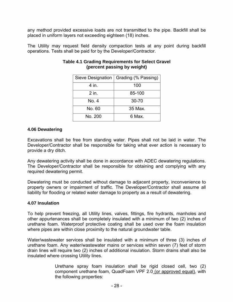
4.05 Backfill and Compaction Under normal circumstances, backfill material will be the native material obtained during excavation. The material shall be thawed and have a reasonably low moisture content. Backfill material shall be free from organic material, debris, broken pieces of concrete or asphalt, large stones or stumps or any other material that in the opinion of the Utility is unsuitable for backfill. Rejected material shall be removed from the site and replaced with acceptable material. All backfill material shall be compacted to ninety-five (95) percent optimum density. Special bedding material will not normally be required provided the native material is acceptable and can be compacted. Pipe bedding shall be placed so as to ensure the pipe is given a uniform bearing for its full length. If native material is unacceptable, the pipe shall be bedded in select gravel (see table 4.1 grading requirements). The first backfill lift shall not exceed the spring line of the pipe. The second lift shall be to the top of pipe. Each lift shall be compacted to ninety-five (95) percent optimum density prior to placement of subsequent lifts. Backfill above the pipe may proceed with
- 28 -
any method provided excessive loads are not transmitted to the pipe. Backfill shall be placed in uniform layers not exceeding eighteen (18) inches. The Utility may request field density compaction tests at any point during backfill operations. Tests shall be paid for by the Developer/Contractor.
Table 4.1 Grading Requirements for Select Gravel (percent passing by weight)
Sieve Designation Grading (% Passing)
4 in. 100
2 in. 85-100
No. 4 30-70
No. 60 35 Max.
No. 200 6 Max.
4.06 Dewatering Excavations shall be free from standing water. Pipes shall not be laid in water. The Developer/Contractor shall be responsible for taking what ever action is necessary to provide a dry ditch. Any dewatering activity shall be done in accordance with ADEC dewatering regulations. The Developer/Contractor shall be responsible for obtaining and complying with any required dewatering permit. Dewatering must be conducted without damage to adjacent property, inconvenience to property owners or impairment of traffic. The Developer/Contractor shall assume all liability for flooding or related water damage to property as a result of dewatering. 4.07 Insulation To help prevent freezing, all Utility lines, valves, fittings, fire hydrants, manholes and other appurtenances shall be completely insulated with a minimum of two (2) inches of urethane foam. Waterproof protective coating shall be used over the foam insulation where pipes are within close proximity to the natural groundwater table. Water/wastewater services shall be insulated with a minimum of three (3) inches of urethane foam. Any water/wastewater mains or services within seven (7) feet of storm drain lines will require two (2) inches of additional insulation. Storm drains shall also be insulated where crossing Utility lines.
Urethane spray foam insulation shall be rigid closed cell, two (2) component urethane foam, QuadFoam VPF 2.0 (or approved equal), with the following properties:

- 29 -
K Factor: 0.14 (Btu - in/FT2 - Hr - °F) at 40ºF Compressive Strength: 25 psi Density: 2.0 pcf
Protective Coatings shall be a two (2) component, one hundred (100) percent solids, sprayable polyurethane coating, Permex 700 by Resin Technology (or approved equal) with the following properties:
Tensile Strength: 1800 PSI Elongation (percent): 120 Water Vapor Transmission: 0.413 Perms
Applicator shall demonstrate prior experience of at least two (2) years. The Utility shall be the sole judge of the qualifications of system, application method, and applicator. The Developer/Contractor shall furnish labor, materials, equipment and services necessary for, and incidental to, application of spray urethane foam.
Insulation shall be applied to Utility mains above ground in a local yard. Mains shall not be insulated in the ditch except under special circumstances, which must be approved by the Utility.
Hydrants, valves and manholes shall be insulated as shown on the standard drawings. Care shall be taken not to cover hydrant drain holes. Pre-insulated pipe that has damaged insulation due to transportation shall be reinsulated to the satisfaction of the Utility. Backfill shall not take place until all insulation has been inspected. Backfill shall be placed so that pipe insulation will not be damaged. 4.08 Casings Utility mains which must cross the Alaska Railroad, Alaska Department of Transportation (ADOT) Highways and/or other selected roadways shall be placed in bored casing sleeves. Casings shall be placed according to the specific utility permit requirement. Joints inside casings shall be fully restrained. Ends of casings shall be sealed with urethane foam. 4.09 Connections to Existing System Connections to the existing Utility system shall be made by Utility personnel only. Expenses for such connections shall be borne by the Developer/Contractor. Developer/Contractor shall provide a safe excavation with sufficient room to make the connection. At least forty-eight (48) hours of advanced notice is required when requesting a connection. The Utility reserves the right to schedule connections so as to not inconvenience existing customers and minimize potential problems. Connections to the Utility’s water transmission mains or wastewater interceptor lines are not allowed without special consideration and approval by the Utility.
- 30 -
4.10 Services The design and construction requirements for water and wastewater services are outlined in a separate document; SERVICE LINE STANDARDS, which is available on our website at www.akwater.com. Of particular note to Developer/Contractors is the issue of extending service lines to unoccupied lots. Normally, services are only provided to existing structures; however, in a development project where not all houses are initially constructed and the remaining improvements such as sidewalks, paving etc. will be completed; it would be unreasonable to expect customers to excavate the new road for each service connection. In these situations the Utility will allow for future connections with a service stub-out (sewer) or property loop (water) to be installed to each lot in the project area. The water property loop is designed to circulate on its own and thereby prevent freezing. The liability for freezing however still remains with the property owner. Each individual lot on a street to be paved fronting the Utility lines may be provided with a stub-out or property loop which extends into the lot three (3) feet past the property line. In no case will more than one (1) building be connected to the same service. Services shall typically be located no closer than ten (10) feet from interior property lines. If the property loop is placed in the same trench with the wastewater service, the bottom of the water pipes at all points shall be at least one (1) foot above the top of the wastewater service. The water and wastewater services shall maintain a one (1) foot horizontal separation and wastewater shall be one (1) foot below water. Electronic markers, as manufactured by 3M, shall be placed over the ends of all service connections. Service connections belong to the property owner of the lot served. The property owner shall be responsible for the maintenance and all other costs associated with the service connection. The utility will record at the district recording office “NOTICE OF NON-COMPLIANCE OF UTILITY SERVICE LINE HOOKUP”. This will notify all interested parties that the service connection exists and is the property owner’s responsibility. 4.11 Traffic Control a) General The Developer/Contractor shall perform actions necessary to protect and maintain traffic during the life of the contract, including the furnishing of such personnel, equipment and devices as may be required to insure the safety of the traveling public. The Developer/Contractor shall be responsible for obtaining and complying with all required street excavation or traffic control permits, as issued by State of Alaska ADOT, City of Fairbanks or FNSB.

- 31 -
b) Public Notification In the event that the planned construction will affect the public, the Developer/Contractor shall post a notice to the public in a local daily newspaper advising the public of the project boundaries including a scale map showing the project area and suggested detour routes, the project time limits, the general contractor's name, and the need to be alert for construction signs and traffic control. The notice, dimensioned 3" x 5" minimum, shall appear once fourteen (14) days prior to the start of work and continuously for seven (7) days beginning five (5) days before the start of work. c) Traffic Control Signage All traffic control devices used by the Developer/Contractor shall be placed and maintained in accordance with the requirements as specified in the Manual on Uniform Traffic Control Devices (UTCM) with Alaska Supplement. No construction operation will be allowed to commence until the Developer/Contractor has obtained the proper signs and placed them as required by UTCM. Hastily made hand painted signs and barricades will not be permitted. d) Access The Developer/Contractor will be required to: maintain pedestrian access to all residences and businesses in the construction zone; maintain vehicle access for emergency vehicles, fire trucks, ambulances and police vehicles; provide barricades and flagging personnel as necessary while working in all areas and in particular busy intersections on the project. Ditch openings which isolate businesses and other areas as specified by the engineer shall be provided with an approved bridge system capable of withstanding traffic loads to those areas. No road or business driveway may be closed without the approval of the Utility Engineer unless the Developer/Contractor has received written authorization from the owner affected. e) Open Work At no time will the Developer/Contractor have more than one thousand (1,000) feet of trench open, nor more than two (2) existing intersections closed to vehicular traffic. Pedestrian access crossings suitably equipped with handrails shall be provided. The cost of such crossings, if required, shall be the responsibility of the Developer/Contractor. f) Barricade Warning Lights Barricade warning lights shall be provided and maintained at all barricades and at all other points where directed by the engineer and shall be kept continuously functioning from one (1) hour before sunset until one (1) hour after sunrise.
- 32 -
g) Agency Notification The Developer/Contractor is required to notify the following agencies at least twenty-four (24) hours prior to starting any work which might inconvenience or impact vehicular traffic. Information on project area, duration and detour routes should be provided. City of Fairbanks Fire Department 459-6500 City of Fairbanks Police Department 459-6500 City of Fairbanks Public Works 459-6896 Department of Transportation 451-2206 University Fire Department 474-7721 Alaska State Troopers 451-5100 FNSB - Transit 459-1002 FNSB - School Bus 452-2000 x351 or 352 4.12 Construction Surveying The Developer/Contractor shall perform all surveying and staking essential for the completion of the project in conformance with the plans and specifications and shall perform all necessary calculations required to accomplish this work. Monumentation shall be in accordance with State of Alaska Standard Drawings. The Developer/Contractor shall use competent personnel and suitable equipment for the layout work required, and shall furnish all equipment necessary for checking and maintaining lines and grades. Upon the Utility’s request, the Developer/Contractor shall provide evidence acceptable to the Utility that the individual who is proposed to perform the construction staking has a minimum of three (3) years experience in similar construction staking work, is knowledgeable in the operation of required staking instruments and is capable of reading, understanding and accomplishing the construction survey work described herein. All lot corners adjacent to, or within the area of the construction project that are destroyed or disturbed by the Developer/Contractor, shall be replaced at the expense of the Developer/Contractor. All surveying work requiring the setting/resetting of monuments, property corners and all permanent survey monuments shall be accomplished under the direct supervision of a Registered Land Surveyor, licensed in the State of Alaska. All control, alignment, or grades necessary for construction shall be the responsibility of the Developer/Contractor. All alignment and grades shall be set in such a manner that they can be checked by the Utility. The Developer/Contractor shall be responsible for the supervision of the construction surveying personnel. Any errors resulting from the preparations of said personnel shall be corrected at the expense of the Developer/Contractor, at no cost to the Utility. If field measurements or construction work is necessary to determine quantities or verify
- 33 -
proper installation, that work shall be performed by the Developer/Contractor's survey crew under the supervision of the Utility. At any point during construction, including prior to backfilling, the Utility may require the Developer/Contractor to provide verification that the pipes or other Utility structures are set to the proper plan grade. Any facility placed outside of the specified tolerances shall be regraded at the Developer/Contractor’s expense.