standardized command posts · workspace design handbook for standardized command posts ... design...
TRANSCRIPT
00
0) Research Product 90-29
Workspace Design Handbook forStandardized Command Posts
DTICS ELECTEDEC11 1990 LI
September 1990 E
Fort Leavenworth Field UnitSystems Research Laboratory
U.S. Army Research Institute for the Behavioral and Social Sciences
Approved for public release; distribution is unlimited.
90 12 11 113
U.S. ARMY RESEARCH INSTITUTE
FOR THE BEHAVIORAL AND SOCIAL SCIENCES
A Field Operating Agency Under the Jurisdiction
of the Deputy Chief of Staff for Personnel
EDGAR M. JOHNSON JON W. BLADESTechnical Director COL, IN
Commanding
Technical review by
Stanley F. BolinNigel Nicholson
Accession ForNTIS- CFA&I-4DTIC TAB3Unannounced Ejust if ication
ByDistribution/
Availability CodesAvail and/or
9 Dist Special
NOTICES
DI RIBUT Primary di iu on of du rt has bee by ARI. Pladesco pord ce c "ceni istrib ion of rts :U.S AyR earch nR' ftefth-Be avi and ia jences, ERI-P I Eisenh er ,Alexartb*Ign1~.
FINAL DISPOSITION: This report may be destroyed when it is no longer needed. Please do notreturn it to the U.S. Army Research Institute for the Behavioral and Social Sciences.
N")TE: The findings in this report are not to be construed as an official Department of the Armyposition, unle~is so designated by other authorized documents.

UNCLASSIFIEDCURITY CLASSiFICATiON OF THIS PAGE
Form ApprovedREPORT DOCUMENTATION PAGE OMB No. 0704-0788
a. REPORT SECURITY CLASSIFICATION lb. RESTRICTIVE MARKINGS
nclassified --
a. SECURITY CLASSIFICATION AUTHORITY 3. DISTRIBUTION/AVAILABILITY OF REPORT-_'Approved for public release;
b. DECLASSIFICATION /DOWNGRADING SCHEDULE distribution is unlimited.
* PERFORMING ORGANIZATION REPORT NUMBER(S) 5. MONITORING ORGANIZATION REPORT NUMBER(S)
RI Research Product 90-29 --
a. NAME OF PERFORMING ORGANIZATION 6b. OFFICE SYMBOL 7a. NAME OF MONITORING ORGANIZATION
.S. Army Research Institute (If applicable)
ort Leavenworth Field Unit PERI-SL --
c- ADDRESS (City, State, and ZIP Code) 7b: ADDRESS (City, State, and ZIP Code)
.0. Box 3407ort Leavenworth, KS 66027-0347
a. NAME OF FUNDING/SPONSORING 8b. OFFICE SYMBOL 9. PROCUREMENT INSTRUMENT IDENTIFICATION NUMBERORGANIZATION U.S. Army Research (If applicable)
nat~tutelf~r.the Behavioral P-.na ocla_ bciences -PERI-S
Ic. ADDRESS (City, State, and ZIP Code) 10. SOURCE OF FUNDING NUMBERS
PROGRAM PROJECT TASK WORK UNIT001 Eisenhower Avenue ELEMENT NO. NO. NO. ACCESSION NO.
Llexandria, VA 22333-5600 63007A 793 1304 H3
1. TITLE (Include Security Classification)
lorkspace Design Handbook for Standardized Command Posts
12. PERSONAL AUTHOR(S)7allesen, Jon J.; and Quinkert, Kathleen
13a. TYPE OF REPORT 13b. TIME COVERED 14. DATE OF REPORT (Year, Month, Day) 15. PAGE COUNT'inal I FROM 90/02 TO 90/07 1990, September I16. SUPPLEMENTARY NOTATION
17. COSATI CODES 18. SUBJECT TERMS (Continue on reverse if necessary and identify by block number)FIELD GROUP SUB-GROUP Workspace layout Staff operations Functional analysis
Human factors Design Link analysis
Command posts Environment
19. ABSTRACT (Continue on reverse if necessary and identify by block number)This handbook was developed for use in the Army Chief of Staff's Standardized Command
'ost program. It provides recommended design techniques, assessment approaches, sample)perational considerations, human factors guidelines, and implementation advice for the designIf Army tactical command posts. All information in the handbook is based on subject matter:xperts' knowledge of human factors design and soldier performance. The handbook discusses)perational considerations in terms of standardization and establishment of operationalequirements for workspace design. It also points out the need to go beyond arranging;quipment in command post design and describes how to incorporate the soldiers and their
lissions in design. s , , ,. .,, ,
20. DISTRIBUTION:AvAuLL,I.II Y UF ABSTRACT 21. ABSTRACT SECURITY CLASSIFICATION.- UNCLASSIFIEDUNLIMITED 0 SAME AS RPT. 0 DTIC USERS I Unclassified
!2a. NAME OF RESPONSIBLE INDIVIDUAL 22b TELEPHONE (Include Area Code) 22c OFFICE SYMBOL
Jon J. Fallesen I (913) 684-4933 1 PERI-SL
iD Form 1473, JUN 86 Previous editions are obsolete. SECURITY CLASSIFICATION OF THIS PAGE
UNCLASSIFIEDI

Research Product 90-29
Workspace Design Handbook forStandardized Command Posts
Jon J. Fallesen and Kathleen QuinkertU.S. Army Research Institute
Field Unit at Fort Leavenworth, KansasStanley M. Halpin, Chief
Systems Research LaboratoryRobin L. Keesee, Director
U.S. Army Research Institute for the Behavioral and Social Sciences5001 Eisenhower Avenue, Alexandria, Virginia 22333-5600
Office, Deputy Chief of Staff for PersonnelDepartment of the Army
September 1990
Army Project Number Human Factors in Training20263007A793 Operational Effectiveness
Approved for public release; distribution is unlimited.
III

FOREWORD
The U.S. Army Research Institute for the Behavioral andSocial Sciences (ARI) Fort Leavenworth Field Unit conducts anextensive program of research on soldier performance in commandand control (C2). The Field Unit's research accomplishmentsinclude a successful track record of resolving critical behav-ioral concerns that occur because of the introduction of automa-tion into command posts. This research supports the developmentof a tactical C2 system that can be fully integrated into commandpost operations and that helps the soldiers in the performance oftheir tasks.
The Director of C2, Combined Arms Combat Developments Activ-ity (CACDA), obtained ARI's assistance with the Standardized Com-mand Post project when it was resumed during the summer of 1989.The role .f the ARI Fort Leavenworth Field Unit was to serve as aconsultan on human performance matters in the redesign of bat-talion through corps command posts and in the design of futurecommand posts to be equipped with emerging tactical communica-tions and computers. These responsibilities were established inthe Standard Command Post Letter of Instruction 1-89, dated 29June 1989, from the Doctrine and Training Branch of C2, CACDA.The ARI work was performed under the memorandum of agreementbetween CACDA and ARI entitled "Development and Implementation ofthe Future Battle Laboratory," dated 30 June 1989. This handbookwas coordinated with the Director of C2, CACDA, and Chief of theStandardized Command Post (SCP) project. An earlier version ofthe handbook was provided to the sponsors for use as ARI WorkingPaper LVN-90-01 during March 1990.
The need for consistent guidance to address the needs of thesoldiers in design became evident after several versions of SCPdesigns were developed and presented for review. In February of1990, ARI offered to develop a set of workspace guidelines forCACDA based on manpower, personnel, human factors, and safetydesign criteria. This handbook represents the compilation ofdesign guidelines to be used by the SCP combat developers for thefuture command post designs. This handbook reflects the assis-tance of many individuals and agencies; most notably the Fssis-tance provided by the U.S. Army Human Engineering Laboratory andthe MANPRINT office at the Natick Research, Development, andEngineering Center.
ED ARM. OHNSONTechnical Director
v

ACKNOWLEDGMENTS
Many individuals contributed to this handbook. Ms. CynthiaBlackwell from the MANPRINT office at the U.S. Army ResearchDevelopment and Engineering Center (RD&E) provided numerous sug-gestions for improvement to a working draft. Dr. Edwin Smootzfrom the U.S. Army Research Institute for the Behavioral andSocial Sciences (ARI) contributed the section on using simula-tions and modeling for design and user assessments. Mr. BruceMcCommons from the U.S. Army Human Engineering Laboratory (HEL)coordinated comments from other HEL reviewers and made usefulsuggestions for additions to the draft. Other contributors fromHEL included Dr. Wayne Anderson, Ms. Mary Besterfield-Sacre, Mr.Bob Fox, and Dr. James Walrath. Those contributing operationalexpertise included LTC Arthur H. Tichenor, Chief, Command andControl Doctrine Branch, Command and General Staff College(CGSC); MAJ James Wolfe from the Training Integration and Devel-opment Directorate, Combined Arms Training Activity (CATA); Mr.Al Patterson from the Command and Control Directorate, CombinedArms Combat Developments Activity (CACDA); CPT Ken McDevitt, C2,CACDA; and MAJ Robert Lambert, C2, CACDA. Also Mr. Rex Michel,Dr. Stan Bolin, and Dr. Nigel Nicholson, ARI, made useful com-ments on the draft.
Other individuals contributed by providing information andreferences. These included Mr. Steve Beaudoin, StandardizedIntegrated Command Post System (SICPS), RD&E Center; Mr. RichardBrown, SICPS, CACDA; Dr. James Geddie, HEL; Mr. Dave Gibson,Secure Lighting Office, Communications-Electronics Command(CECOM); Mr. Mike Gravelle and Mr. J. N. Hecht, Crew SystemsErgonomics Information Analysis Center (CSERIAC); and CPT DaveJackson, Maneuver Control System, CACDA.
vi

WORKSPACE DESIGN HANDBOOK FOR STANDARDIZED COMMAND POSTS
CONTENTS
Page
INTRODUCTION........................
DESIGN PROCESS..........................5
operational Considerations...................5Operational Summary......................9Analysis in Design.......................10Design Assessment......................20Design Management......................23
DESIGN GUIDELINES........................25
General "Rules of Thumb"...................25Group Workspace.........................26communications........................30Mobility.............................31Functions and Links.......................31supervision............................32Transient Personnel.......................32Passageways...........................32Displays.............................32Fatigue at Computer Workstations ................ 37Storage...........................39Maintenance.........................39Set-up and Tear-down.....................40Equipment Accessibility....................40Environment..........................43Safety................................46
GUIDELINE IMPLEMENTATION.......................49
Integrating the Design......................49Tailoring the Guidelines....................50Design Assistance......................51
REFERENCES...........................53
APPENDIX A. EXCERPTS FROM ARMY COMMAND AND CONTROL
EMPLOYMENT CONCEPT. ................. A-1
B. SELECTED ANTHROPOMETRIC DATA FOR U.S.
ARMY SOLDIERS...................B-i
C. SAFETY EXCERPTS FROM MIL-HDBK-759 ......... C-i
vii

CONTENTS (Continued)
Page
LIST OF FIGURES
Figure 1. Organization of this handbook ..... ......... 2
2. Workspace design process .. ........... .11
3. Link diagram superimposed overequipment layout ..... ............... .. 18
4. Cut-away drawing of a command postmock-up ....... .................... .22
5. Clearance dimensions around an item
of equipment ...... ................. .. 26
6. Work surface and desk dimensions ....... .. 28
7. Accommodation for dual sit-standoperations ...... .................. .30
8. Dimensions for passageways and aisles ..... .. 33
9. Illustration of the meaning of visualangle ........ .................... .33
10. Example of viewing angle .. ........... .35
11. Good viewing area increases with obliquescreen positioning .... .............. .. 35
viii
WORKSPACE DESIGN HANDBOOK eOR STANDARDIZED COMMAND POSTS
1. INTRODUCTION
The Standardized Command Post (SCP) program is an initiativeto provide guidance to document doctrinal functions,arrangement of shelters, shelter workspace, equipment, andpersonnel. While the equipment and personnel authorizations havebeen standard in the sense of Tables of Organization andEquipment (TOE), operational usage has been very different fromone organization to another. The design of the SCP will be adynamic process combining the shelters and equipment to supportthe required personnel in performance of mission essentialfunctions. Workspace layout combines these design elementstogether into an effective system. Designs of the past haveconsidered the equipment, but they have not always been optimizedfor effective, efficient, and safe operation by soldiers.Soldiers and what they have to do to accomplish their missionare paramount in the development of SCP.
This handbook has been put together for combat developers atTraining and Doctrine Command (TRADOC) proponent centers andschools who hold the responsibility for planning SCP andimplementing the SCP concepts in doctrine and institutionaltraining. SCP is not a typical Army design effort because it isnot rooted in the established requirements processes andacquisition procedures. Since the combat developer is performinga unique role in the SCP program and will not be familiar withthe full range of design requirements, this handbook providestailored guidelines for soldier considerations. The handbookshould also serve as a useful reference for materiel integratorsand human factors practitioners who support the SCP program.The general premise of this handbook is that soldierconsiderations must be solidly integrated into the workspacedesign process, rather than only designing for shelters andequipment and assuming that the soldiers' needs will be met orthat soldiers will adapt to the environment.
Workspace layout is not a new problem. It has been wrestledwith by many in the industrial community, as well as the Army,under the term human factors. The SCP designer should know aboutthe implications of these factors, and they should design usingstandard and accepted procedures for addressing soldierconsiderations. This handbook identifies procedures andguidelines to ensure SCP designs that facilitate effectiveperformance. Guidelines are provided that have been taken frommilitary standards and handbooks and other industrial and Armyliterature. Examples are given on how to tailor and put theseguidelines into practice. This handbook alone will not make acombat developer into a seasoned practitioner of human factorsdesign. Its main purpose is to introduce design techniques andsoldier equipment interface guidelines. This handbook lays out ageneral procedure for SCP design and highlights critical soldier
1

1. INIRWUTCIOM
considerations to use in integrating existing materiel andshelter components.
The handbook is divided into fivesections and three Appendixes as
lwoWsPce presented in Figure 1. Section 1|ANDBcOK FOR addresses the background andSTANDARDIZED rationale for these guidelines.
POSTS oSection 2 recommends a process tofollow for SCP design. It addresses
Section 1. the importance of specifyingNT ou, N J operational constraints and goals.Section 2. Also Section 2 describes analysisDESIGNPRO°CESS techniques necessary for appropriate
Section 3. workspace design and approaches forDESIGNGUIDELNES assessment of the designs. General
Sect ion 4. and detailed guidelines areGUIDLINEpresented in Section 3. Section 4IMPLMENTTIONpresents a summary of design/ ~Ilon S.
Rconsiderations and examples oftailoring the guidelines. Section 5
APPENDNES; includes the references that arerecommended to obtain more
Figure 1. organizationof information.this Handbook. Link analysis is one of the
procedures described in Section 2.The goal of link analysis is to economize the movement ofpersonnel, information, and products. The groupings of equipmentand personnel are examined to optimize the links among them.Link analysis will help determine the best functional groupingsof staff elements and the most efficient layouts of workspace.Less movement of staff and information translates to faster andmore efficient command post operations, which in turn will leadto effective performance.
Above all else, the workspace must be designed so thateffective performance is achieved.
The basis for the guidelines contained in Section 3 follows thissame premise. In order to perform effectively, command postpersonnel need to have sufficient room to move around andiiteract with fellow staff. They need furnishings that providethe proper features and dimensions. When computer workstationsare incorporated into the command post, precautions need to betaken to prevent operator fatigue. Also the staff must be ableto access and view all displays. The command post environmentmust be designed for safety and to provide adequate lighting andtemperature. Performance over prolonged, stressful periods ofcommand post operation must be supported by optimizing the
2
functionality of the workspace. These examples represent some ofthe guidelines that are covered in this handbook.
With this handbook the designer should produce a moreefficient and effective command post because a conscious effortwill ha.vc bccn made to design to fully integrate the soldier. Byapplying the presented techniques and detailed guidelines thathave proven their usefulness in industrial and Army design alike,the designers can increase their confidence that an effectivesystem will be produced.
3
2. DESIGN PROCESS
Operational Considerations
A command post, just like command and control, does notexist for its own sake. It is there to support the commander andhis staff in commanding a force to win a battle. This context isnot likely to be forgotten in the design of the command post.But because this relationship is so obvious, the specification ofthe operational requirements may be overlooked.The operational goals and constraints of the command postorganization must be carefully identified to provide the properframework for command post design.
The following paragraphs discuss ten different issues -hatare being referred to in this handbook as operationalconsiderations. The result of considering these operationalfactors will be the specification of required capabilities of thecommand post. These issues need to be addressed and policydecisions made about the way a command post will operate. Thesedecisions are important so that designers, developers, and usersunderstand how the command post will be employed and in whatenvironments. These considerations have direct impact ondesigning for the soldier.
Operational environments. The operational environmentsshould be specified in which the command post must function alongwith the relative expected priority of each. The operational andorganizational (O&O) concept and required operationalcharacteristics (ROC) for the Army Tactical Command and ContrclSystem and individual battlefield functional area systems aresources for this information. Excerpts on the operational andorganizational modes from the Army Command and Control Systememployment concept are provided at Appendix A. For example, thenormal missions of an armored division include desert and winterwarfare, while assignments to jungle and mountain warfare are oflow probability. The guidelines in Section 3 provide examples ofenvironmental parameters that need to be considered formaintaining an adequate and safe environment for soldiers.
Nuclear, biological, and chemical (NBC) warfare is a normaloperating environment that all tactical forces must be preparedfor. Operations in potential NBC environments require specialdesign forethought. The designer will need to know whether thecommand post will sustain operations in an NBC environment orwhether they will withdraw once NBC conditions are present. Forsustained operations, there may be additional requirements on thecommand post design to provide for over pressure, an entryvestibule, storage of extra military operations protectiveposture (MOPP) clothing, and extra drinking water. If the setpolicy will be to withdraw from a threatened area, then ha'-ing
5

operationat Considerat ions
appropriate monitoring equipment and warning procedures increasein importance, as well as the time lines for tear-down anddisplacement.
Detectability. Limiting detection by disciplining light,noise, and other emissions is a key operational concern.Lighting requirements are based on the capabilities of nightvision devices to detect low energy sources in the visible andnear infrared spectrum. Expected command post locations on thebattlefield needs to be taken into account to determine the levelof precaution necessary for lighting and noise discipline.Guidelines for secure lighting and aural nondetection areincluded in Section 3.
Dispersion. Dispersed command post operations is one of theprimary drivers for SCP. The design needs to recognize thedoctrinal parameters of achieving dispersion. Specifically, theparameters to be identified for each command post are: minimumand maximum distances among command posts, frequency ofrelocation, and percentage of TOE moved in one segment usingorganic vehicles. Minimum distances establish the safe distancefor locating one command post next to another. Maximum distancesestablish the extent to which command posts can be located inorder to maintain contact with one another and with theirsubordinate forces.
Redesign of command posts allows an increase in theapplication of principles of battlefield survivability. That is,it reduces the likelihood of detection by .creasing physicalsignatures and designation by using consis.ent site layouts fromone command post to another. Smaller command post sizes andimproved vehicles increase the mobility of command posts. Adispersed concept also allows the separation of emitters. Thesmaller physical size of command post cells better supports thegoal of "blending" into the existing environment; by locatingwithin factories, warehouses, and other buildings. Smaller, morenumerous command post cells will supply the personnel andequipment capabilities for redundancy of functions, which alsowill increase the chances for survivability of command.Dispersion will be possible because of the emerging capabilitiesfor computer-supported cooperative work (CSCW), also known asshareware or groupware. This "electronic collocation" counterssome of the disadvantages of separating staff.
Increased dispersion creates new challenges for soldierperformance areas like communications and staff interaction.Dispersion is not without disadvantages. For example, there willbe added costs because equipment cannot be shared as much.Requirements for generators, computers, test equipment, toolkits, shelters, life support activities, and site security will
6

2. DESIGN PROCESS
increase when functions and staff elements are more widelydispersed. But it is critical for survivability to disperse.
Back-uns. Back-up capabilities also need to be consideredfor dispersed command posts. One advantage of the dispersedcommand post concept is that one command post element can assumethe duties when other elements relocate. The workspace designshould accommodate these alternative operating modes. Alsosimilar considerations for back-up capabilities apply under"graceful degradation" to sustain command and control whenpersonnel and equipment are lost. Special considerations need tobe made for procedures, spare equipment, and associated workspacerequirements in the event of tactical computer failures.
Operation-on-the-move. Operation-on-the-move is a possibletactical consideration. The designer should identify what therequirement is, if any, to operate some cell or staff elementwhile moving. This is especially important for operatingtactical computers and communications. For example, operation-on-the-move impacts workspace design by requiring secure, safeseating (e.g., with a five point harness) for computer operatorsand locating necessary equipment within the reach of the seatedoperator.
Continuous operations. Continuous operations have an impacton manpower requirements and scheduling of duty shifts. Theeffects of sleep deprivation are well documented and its effectsare particularly menacing for command and control operations.
Cognitive performance is more sensitive to the effects ofbrief, fragmented or no sleep than physical strength andendurance. So those elements of military operations involvingcognitive abilities will be more affected. Cognitiveabilities are the weak link in human performance in CONOPS.Six to eight hours of sleep each night will maintain cognitiveperformance indefinitely. Three to four hours sleep eachnight will maintain cognitive performance for 5-6 days. Lessthan 3 hours sleep each night will lead to rapid declines incognitive performance and hence military effectiveness.Soldiers can remain militarily effective for only 2-3 dayswith little or no sleep. (p. 1-17, Belenky, Krueger, Balkin,Headley, & Solick, 1987)
The limits of waking hours without rest are likely to be lowerfor the older soldier.
These well-established findings on sleep loss haveparticularly important implications for maintaining adequatemanpower for dual duty shifts and for providing adequate "lifesupport" considerations.
7

Cperational Comidrations
Sleep deprivation results in . . . decreased capacity forsustained selective attention, and therefore a diminishedcapacity for efficient performance of higher level cognitivetasks (Kjellberg, 1977). Performance on cognitive tasksrequiring calculations, creativity, and the ability to 'planahead' effectively are especially sensitive to sleep loss..The implications of these studies are particularly importantfor command and control personnel because the abilities thatenable soldiers at all levels of command and control torespond quickly and effectively to constantly changingbattlefield conditions -- abilities to quickly anticipate,recognize, and correct areas of weakness in their owndefenses, as well as to anticipate, recognize, and takeadvantage of opportunities to seize the initiative fromattacking forces -- are the abilities that will be , .raded bysleep loss. (p. 1-2, Belenky, Krueger, Balkin, Hea, .ey, &Solick, 1987)
Set-up and tear-down. The ease and speed of set-up, tear-down, and time in transit for command post units are alsooperational considerations. These constraints increase inimportance as the frequency of moves increases and the need forrapid set-up/tear-down increases. (Appendix A identifiesrepresentative mobility characteristics of command posts.) Oneoutcome of down-sizing command posts and shelters is theassociated reduction in the number of soldiers per command post.With fewer soldiers, it may be difficult to reach the requiredminimum for fast and safe set-up for tasks requiring simultaneousaccions, (for example, tent set-up requiring at least threesoldiers or lift requirements of heavy equipment).
Shelter arrangement. The arrangement of shelters can havean affect on the sequence and speed of the set up operation. Forexample, placing M577s side-by-side can speed up the set-up ofextensions, because they can be set up simultaneously withoutsurveying distances. When M577s are arranged end-to-end orperpendicular, the first M577 needs to be positioned and theextension set up started before the next M577 can be positionedand its extension set up.
Arrangement also affects the shape of the workspace.. Someshelters can be joined together to create a large common workarea, or they can be arranged to make small, separate workingcompartments. Typically in command posts, arrangements aredesired that do both. Careful design considerations will need tobe given to meet both criteria and to obtain rapid set-up andtear-down.
8

2. DESIGN PROCESS
Ecruipment off-loadinQ. Another consideration is the off-loading of equipment for operation. For example, the VFMED(Variable Format Message Device) is supported by a vehicularmount in an M577. The TCT (Tactical Computer Terminal) can bemounted in the M577 or down loaded for operation in a tent. Forexample, set-up time would be less if a computer is left in itsM577 carrier for operation. But if an extra soldier is needed tocarry message traffic back and forth between the M577 tentextension and the computer during operations, then there may bean overall loss in efficiency and added manpower requirements.In expansible vans, MCS (Maneuver Control System) computers canbe placed over the main body of the platform rather than over theoutriggers to save set-up time and to better centralize weightdistribution. However, locating all fixed equipment near thecenter line of the van also places considerable limitations onpossible workspace arrangements. The designer may come up with agood static "load plan," but one that does not support thedynamic operations and movement of the staff. There will surelybe trade-offs between speed of emplacement (and weight/bulk ofequipment) and having the equipment in the best location tosupport the essential functions.
Classified information. Operational considerations need tobe given to the requirements for restricting classifiedinformation from unauthorized personnel. With the tendencytoward smaller command posts there may not be enough personnel orspace to allow the proper procedures for dealing with classifiedinformation. The designer should be sure that enough personnelwith the appropriate clearances and training are identified andthat adequate workspace considerations are made.
Operational Summary
This discussion of operational constraints is not exhaustiveof the factors to be used in design. This initial list isprovided to give some indication of how soldier performanceissues and operational considerations go hand-in-hand to impactdesign. The operational considerations do need to be articulatedby the designer as statements of goals and constraints thatimpact the design process. Also these considerations provide thebasis for explaining why command posts are structured as they areand will be useful to understand the design background ascircumstances require changes and improvements. Mostimportantly, they provide the "mark on the wall" to setrequirements for the design process and to use in trade-offsbetween conflicting constraints.
9

Analysis in Design
Analysis in Design
There are two levels of design that should be considered.rirst i tho organizational perspective: looking at thegroupings and locations of functional command posts and cells.The second is the detailed workspace layout. Alternativelocations for staff elements and groupings of staff within alocation makes up the organizational level of design.Specification of functions and detailed tasks should be performedfor organizational design to determine the groupings of functionsbefore the more detailed process of manning and workspace layoutare considered. There should be iteration between the twolevels. Issues will come up at the shelter level that willrequire larger organizational changes.
Overview of desiQn techniques. The functions of command andcontrol must be articulated in such a way that in analysis,design, and evaluation there will be enough information to makelogical trade-offs and decisions. A functional analysis is thetechnique to decompose the overall mission of a commandorganization in successive levels of detail to produce a detaileddescription of the jobs, tasks, and processes. A manpowerazalysis will provide an estimate of the quantities of personnelneeded to perform the functions. The closely related workloadanalysis will help identify the level of effort that is requiredof the soldiers to perform the various functions. It should helpto identify excessive levels of workload as well as thosepositions that have spare capacity for taking over some of theexcessive workload. With the functions and personnel identified,one can develop the required list of equipment and perform a linkanalysis. The link analysis will produce the strength ofinterrelationships among the multiple soldiers and elementsmaking up the command organization. It is also used to determinethe good locations and most important communications amongelements to use in workspace design. During the design processand after, design assessment is important to be sure that themore important design goals are not overtaken by minor goals orconstraints. Repeated evaluations using prototypes can help testdesign and performance assumptions. Throughout design it isimportant to follow good design management procedures. Therelationship of these analysis, assessment, and managementguidelines are illustrated in Figure 2.
It must be pointed out that what is recommended here is aseries of analyses, that is a sequence where the outpu of oneanalysis would feed later analyses. However, the analyses cannotbe treated only as a sequential process. Each of the techniquesbenefits from the outputs of the others. Each requires a set ofinputs or at least assumptions from the others. The designerwill need to work through these interrelationships.
10

2. DESIGN PROCESS
0 .0 --(U
S 0 40 m
c E 0 L (
UJI Af 0 y
U) 0
W. to
C 4A0 C CD
to 0 E0 0 c.
0 CLU, U) f 0
C0 0* U
0 IE
-C C
.22E~(U0 0,3? 0 -0M
.0 r C0 0 ;,. a c -g
.Po (U to 0 q~.~ 'c
~ ~.2 2
0 0
Zl 0 a, F
8.0
X
o L 0
0IO
00
z 00
0 LU 0
U iE PA LU5U
z 0 1

Analysis in Design
Functional analysis. Functional and task analysis are thebasic tools of industrial engineering and human factors. (Notethat most distinctions between functions and tasks are fairlyarbitrary with the difference primarily being the level of detailon the task. Functional analysis and task analysis will be usedinterchangeably in this discussion.) These methods, firstdeveloped by industrial engineers for designing efficientprocesses for assembly processes, are commonly applied to a widerange of human factors applications. The methods should be usedto sort out and articulate what tactical command posts do and howthey do it. In order to design efficient workspaces, the tasksand relationships among them must be thoroughly understood.
Command posts can be viewed as organizations for processinginformation to make timely decisions. In command posts, likefactories and offices, processes merge specialties together andare characterized by information flow. Functional analysis isused to describe these processes and the correspondinginformation flows. Functional analysis can be documented usingvarious approaches. The important aspect of functional analysisis that it provides a method to break down the processes of anorganization into elements for analysis. At the proper level,sufficient detail is available to use for many design actions.
Design of command post operations and facilities isparticularly complex because of the interaction among componentsand the uncertainty inherent in battlefield operations (forexample, intent and actions of opponent, status of own forces,unknown timing, uncertainty regarding future events). Also theorganizational groupings of command posts are complex. Theorganizational and functional adaptability which staffs must haveto respond to special battlefield requirements adds to thecomplexity for the designer. These dynamic requirements accountfor large variations in what tasks are performed, how they areperformed, how often they are performed, and by whom. Because ofthe complexity and variation it is important to break downprocesses to a very detailed level. It is important to recognizethe variability in how functions are performed and to define orincorporate existing standards for the quality of taskperformance that needs to be maintained. Both standards andvariability should be assessed to determine the impact onalternate design concepts.
Functional analysis of command post operations shouldproduce a set of information to be used in design. An exampleset of information categories and a format for a single functionis presented (based in part on draft MIL-STD-1478; Myers,Tijerina & Geddie, 1987).
12

2. DESIGN PROCESS
This information willFunction name: be used to address
personnel, manpower,Information required: organizational, and
workspace needs. ForActions, operations, decisions: example, the required
actions, knowledge, andKnowledge, skill requirements: skills help define the
personnel requirements;Simultaneous tasks: frequency, criticality,
Coordination with others: coordination, andsimultaneous tasks helpdetermine the requiredNumber of personnel: manpower levels; and so
Product produced: forth. All of thefunctional informationcategories impact on
Action or product descriptors workspace design.
Criticality:Frequency: All man-loading tasksAccuracy: need to be specified or theWork rate: designer runs the risk ofTime to complete: not designing for enough
people and workspace. TheLocation (staff element): priority and frequency of
functions will be twoprimary criteria in determining the location of functions and theindividuals who perform those functions.
Task analyses should be done as a partnership betweensubject matter experts (doctrinal authors, trainers, andpractitioners) and job designers (human factors specialists,industrial or behavioral psychologists). Though this analysismay seem to be overwhelming, many good sources exist that serveas starting points to identify functions and tasks. Theseinclude field manuals like FM 101-5, training manuals like ARTEP100-15 MTP, and system descriptions like Magnavox (1988) producedfor the Army Tactical Command and Control System (ATCCS).Technical literature is another good source of information.Carter, Archer, and Murray (1988) provide functional flows anddescriptions of division-level staff operations. Bean,Ottenberg, and Mukherjee (1983) provide functional flowdescriptions for battalion through corps echelons. Scheiber,Bryden, Hargis, and Maggelet (1986) produced functional flows forsimilar allied operations. Comprehensive information and productflows for the corps, division, and brigade Force Level ControlSystem (FLCS) should be very useful (Command and Control, 1990).A comprehensive task analysis on higher echelon staff operationsis reported by Modisette, Michel, and Stevens (1978). These lasttwo references probably best represent the intent and information
13

AnaLysis in Design
that SCP designers should try to emulate.
Job design. Job design is one way to structure how theorganization gets done what is required. In job design therequired functions and tasks are taken and clustered into unitsof work for people. These units of work are called jobs. Somegeneral guidelines for job design are listed in the followingbox.
Tasks assigned to one job should require similar and relatedknowledge and information.
Tasks assigned to a given job should be done in the samelocation.
Tasks closely related in function or in time should beassigned to one job.
Tasks assigned to a given job should relate to the sameequipment or subsystem. (p. 68, Chapanis, 1977)
Manpower analysis. Manning is the activity of specifyingthe number of people needed for each of the jobs in theoperation. The task analysis and job design are used to addresshow many people are needed to perform the required functions andwhat skill requirements are needed (Meister, 1985). Someprinciples for manning are shown in the following box.
The manning should ensure that all the day-to-day activitiesof the system get done.
The manning should provide for all emergency actions that canreasonably be anticipated.
The manning should schedule normal work and offtime periods,providing enough personnel to keep the system in operationover a long period of time.
The manning should include as few different jobs as possible.The manning should make use of as few different people aspossible.
The manning should require as little training time as possibleto keep the system up to its full strength. (p. 68, Chapanis,1977)
14
Z. DESIG PRO=SS
Identification of the manning requirements is perhaps themost difficult of the analysis steps. No known analyses havebeen performed that address the quality of command organizationperformance as a function of manpower or personnel. As such, fewdata exist for manning and personnel decisions.
Manning for command and control operations seems to belargely determined by having the proper branch specialtieslocated together at a command post. Dual shift operations arealso a factor in determining the number of representatives from astaff specialty. Additional soldiers are included for critical--but often overlooked--"housekeeping" functions (for exampledrivers, clerks, messengers). Designers need to establishbetter estimates of the manpower requirements, based onorganizational, task, and workload factors.
Workload analysis. Workload is defined as the capacity toperform (Lysaght et al., 1989). It is often considered inrelative or sufficiency terms, such as
How much spare capacity does the soldier have left toapply to emergency situations or additional tasks?
Are capacity demands consistently at high levels, whichcan lead to overload and, for staff operations, canresult in poor decision making?
Workload is a special consideration that is growing in importanceas sophisticated equipment is relying on soldiers' cognitiveskills as opposed to physical and sensory functions. Of primaryconcern in command posts is cognitive workload as opposed tophysical workload.
The widespread introduction of tactical computer systems incommand posts of the future requires careful consideration ofmanning and workload. Workload analysis is recommended forhelping to identify excessive loading conditions and to serve asan impetus for balancing workload levels and manning requirements(or alternatively to modify the functional requirements).Workload analysis should account for peak operations andemergency conditions. Workload needs to be balanced to avoidexcessive levels. For workload considerations and allocationsboth external and internal command post coordination requirementsneed to be considered.
It is desireable to predict the levels of workload requiredby tasks and equipment and to take steps to prevent overloadconditions. There is no data base of workload in command postoperations that could be used to determine empirically the numberof soldiers required to perform staff work. Without a baseline
15

Anatysis in Design
it is difficult to address overload or peak situations. Numeroustechniques are available for measuring workload and some of themcan be used analytically to predict workload (Lysaght et al.,!6). An'alytical techniques which help structure subject matterjudgments on workload requirements include the McCracken-Aldrichapproach (Aldrich & Szabo, 1986; McCracken & Aldrich, 1984). Inthis approach workload assessments are made by using numericalratings with verbal anchors.
Ratings are made forapplicable workload components 1 - Automatic, simple(cognitive, visual, auditory, association.kinesthetic, and psychomotor) 2 - Sign/signal recognition.for each task. Tasks are placed 3 - Alternative selection.along a relative time line. The 4 - Encoding/decoding, recall.numerical ratings can be summed 5 - Formulation of plans.or combined in some other 6 - Evaluation, judgment.fashion (for example, a weighted 7 - Estimation, calculation,sum or a multiplicative product) conversion.to estimate concurrent workload.If the composite task rating exceeds some pre-establishedthreshold value (for example, a 7 on the visual component), thenan oveiload condition is predicted. Also special questionnairescan be developed (see Babbitt & Nystrom, 1989) to survey subjectmatter experts on expected levels of workload.
Link analysis. Link analysis is used to produce informationon the strength of interrelationships between the differentelements in a workspace. All functions must be specified priorto link analysis, and equipment components and personnel need tobe identified and clustered into initial groupings.
The rationale behind the link analysis technique is that the'best arrrangement' can be found only by optimizing differenttypes of links (such as communication and movement) that areimportant in the particular system being designed. (p. 422,Thomson, 1972)
Link analysis is recommended at two levels in the sequenceof designing SCP. (These correspond to Hendy's category 1 and 2levels of layout applications, 1984). The first link analysisaddresses the groupings of staff elements. The second linkanalysis is done to 'optimize' the workspace layout within acommand post. Closely associated with this is the determinationof communication requirements. The applications at division andcorps will identify groupings of staff into cells. Theapplications below division will identify groupings of staff intocommand posts (tactical, main and rear). The operational
16

2. DESIGN PROESS
considerations may be trade-offs or constraints that will limitthe first link analysis. If a command post has only a singlelocation, the first level link analysis can be skipped. Thesecond link analysis is more detailed and operates on theinformation flow to arrange soldiers and equipment in a givenlocation.
The aim of link analysis is to redraw the workplace so as toreduce the number and length of the links and link crossings,which suggest 'activity' and 'confusion' and thereby produce amore efficient design arrangement. The data required for theanalysis is:
(a) information on flow requirements,(b) flow medium,(c) equipment/operator's requirements,(d) functional allocation,(e) any special constraints. (p.41, Ministry of Defence,
1989)
Many diagrams of command posts identify only the equipmentcomponents. In a network diagram for link analysis, equipmentand people are identified and referred to as nodes and arcs. Therelationships among those nodes are represented as links or arcs.
The term 'link' refers to any connection between a man and amachine or between one man and another. If, for example, oneman must talk to another, this need is represented by a linkbetween them. Similarly, if a man must see the display on amachine or operate a control on a machine, he has a link tothe machine. Links include walking, talking, seeing, andmovement of material and information. (p. 422, Thomson, 1972)
The identified relationships provide the functional meaningto the network and can be used to represent movement of nodes(people or equipment) and information. Some examples of keyrelationships are included in the following box.
17

Aalysis in Design
1. Distance. The distance between nodes.
2. Time. The time required for people, materials, information,and so on to move from one node to another.
3. Frequency. A count of the number of times somerelationship occurs between two nodes. Examples would be thenumber of times an employee walks from one location to anotherin a work environment and the number of eye movements betweentwo displays on a console.
4. Importance. Usually a rating of the importance betweennodes. For example, communications between A and B may bemore important than communications between C and D.Importance ratings are often used in planning layouts orarrangements where it is not yet possible to obtain actualdistance, time, or frequency measures. (p. 342-343, Laughery &Laughery, 1987)
The physical distance and "ease" of communications among SCPequipment and soldiers will impact the frequency with which theequipment is used. Effectiveness will be reduced if prioritycommunications are delayed because of unnecessary steps ininformation flow due to unnatural physical movement or excessivecommunications paths. Link analysis uses the strength andfrequency of interchanges through and among the equipment andsoldiers to determine good locations and arrangements.
The box on the following page describes the steps forperforming a second level link analysis for workspace layout.
8 I
Figure 3. Link diagram superimposed over equipment layout.
18

2. DESIGN PR*OESS
Steps to Follow for a Link Analysis
Step 1. Draw a circle for each man in the system and label itwith a code number for his particular function (e.g., "1" forradio operator, "2" for navigator, "3" for plotter, etc.)
Step 2. Draw a square for every item of equipment used by ahuman operator and label it with a code letter (e.g., "A" forradio, "B" for plotting board, "C" for compass, etc.). Itmakes little difference how the circles and squares arearranged at this point so long as there is some room betweenthem.
Step 3. Draw connecting lines (links) between each man and anyother man or men who have direct interaction in the operationof the system.
Step 4. Draw connecting lines between each man and anymachines with which he must interact.
Step 5. Redraw the resulting diagram, reducing to a minimumthe number of crossing links in order to obtain the simplestpossible arrangement.
Where the preceding steps yield many crossings that revealconflicting requirements for the proximity of men andmachines, it is necessary to evaluate the frequency of use,and the importance of each type of link. When this is true,proceed as follows.
Step 6. Evaluate each link by . . . the following. Where bothfrequency of use and importance of a link must be considered,experienced observers judge the relative weights to be givenso as to assign a single composite value (of criticality orstrength] to each link.
Step 7. Redraw the diagram so that the links having the highervalues are shorter than those having lower link values andreduce the number of crossing links. This is the optimum linkdiagram.
Step 8. Redraw the link diagram, as necessary, to fit it intothe available space or, preferably, design the space to suitthe shape of the diagram.
Step 9. Confirm the final link analysis on a scale drawing ofthe actual positions of the men, machines, and spacescomprising the system. (p 422-3, Thomson, 1972) [see Figure 3]
19

Design Assessment
Application of analysis techniques. There is a tendency tojump too soon to working with the physical elements of design.Almost everyone prefers to deal with what is concrete andtangible, rather than what is abstract and uncertain--as arehuman behavior and command and control tasks.The SCP designer must not proceed to the layout of equipmentbefore the appropriate analyses on operational considerations,soldier functions, and manpower are started.
Design Assessment
Design assessment techniques, which are described below,draw heavily from the design techniques that are recommended inthis handbook.
DrawinQs. Sketches and plan view drawings are two basictools to use in assessing the design and functionality of theworkspace. One technique to use in assessment of the drawings isto picture how personnel would operate by recalling some actualor imagined command post exercise. Try to visualize how theworkspace layout supports or inhibits performance. Focus on the"choke points" that will check the design the fastest: chaoticperiods, final preparation for the commander's briefing, changeof shifts, sudden enemy breakthrough, communications jamming,operation in MOPP 4, set-up or tear-down, transferring control toan alternate command post, etc. Think through the entire segmentof the scenario before making changes to the design. Theimportant thing to do is to identify potential problems and toresolve them collectively--not piecemeal.
Fault analysis. Fault analysis is a technique using nearlythe ;ame visualization process described above. It is related totask analysis; however the focus is on what happens in the human-machine system when emergencies or major failures occur, such asthe loss of a critical radio or computer. Performing faultanalysis during design assessment will determine how faults mightbe prevented by prior design action. To get started the designerwill need to obtain or make failure predictions. A simple methodof conducting a fault analysis is to record the following foreach failure considered:
Failure- condition.Effect of the failure.Possible conditions that would lead to the failure.How a failure is recognized by a soldier.Indications which others would have of a failure.Corrective actions to be taken.Design changes that coild be made.
20

2. DESIGN PROCESS
Stating a failure in terms of how the human would sense thecondition (for example, sees no response on the screen whentyping on the computer keyboard) is probably the best way totrack through the analysis. A simple technique to use is foreach failure to complete a worksheet that has seven columns,corresponding to each of the above considerations. It is advisedthat the technique be used with other methods such as workloadanalysis and time-based task analysis (James & Grober, 1962).
Link analysis. As described above, link analysis is usefulfor assessment in addition to design. Link analysis can identifywhere excessive cross-over interactions occur or where there isinadequate interpersonal or human-machine communication. Thelink diagram itself is a useful visual aid. Alternative designscan be laid side-by-side for a comparison of the one with themost direct links and the fewest cross overs.
Operations research and numerical methods are available tocomputationally evaluate the network linkages. An experimentalcomputer program for workspace evaluation, called LOCATE, hasbeen developed.
[LOCATE) transforms link properties (i.e., length andorientation) into measures of an elemental pair's capabilityto source and receive information. Link strength functionsare chosen to represent human and machine properties which canbe characterized by distance and angular dependentrelationships: the preferred region for locating visualdisplays with respect to the normal direction of view, reachenvelopes, the angular subtense of a display as a function ofviewing distance, or the sound pressure of an audio source.(Hendy, Berger, & Wong, 1989)
Various factors of the LOCATE assessment include the qualityof a link, importance of information sent, importance ofinformation received, attenuation of a link by obstructions,distance and angle dependencies, cost, link priority, andrelative importance of communication media (i.e., vision,audition, tactile, or movement). Input elements include items ofequipment, locations, and personnel.
Simulations. Other computer-based methods are available forevaluating selected aspects of workspace designs. Generalpurpose simulation modeling languages, such as Microsainti, canbe used to model the soldier tasks that must be performed in a
1Microanatysis and Design, Inc., 9132 Thunderhead Drive, Boutder, CO 80302.
21

Design Assessment
given workspace. Microsaint is a menu driven simulation softwarepackage. Another software based method, which complementsMicrosaint, is the Human Operator Simulator (HOS IV) (Harris eta!., 1989). HOS IV contains algorithms to simulate various humancognitive, perceptual, and psychomotor actions. For any givenworkspace design, HOS IV can be used to generate the times ittakes to perform various tasks, such as making simple decisions,storing and retrieving information from short term memory,speaking a given number of words, walking a given distance, andothers. Both of these software tools operate on personalcomputers and can be used to evaluate workspace layouts. As withany method or tool there is an initial investment in time andtraining that is needed for appropriate and effective use.Microsaint can be used after about a week of training andpractice.
Mock-ups. Static mock-ups are another tool to use inassessing layouts (see Figure 4). Scaled models provide a testof the goodness of fit of the equipment, while full-scale mock-ups provide the designer a three-dimensional "feel" for theworkspace. Once a mock-up is available it is useful to use it asa test vehicle as design issues arise (for example to test aquestion like: is there access to the electrical distributionbox around this computer?). Operational prototypes provide thecapability to do partial checks of selected components or to
/f
Fiqure 4. Cut-away drawing of a command post mock-up.
22

2. DESIG PROCESS
accommodate a fully operating staff. Prototypes that are used instaff exercises can be evaluated using various task analysis andhuman performance measurement techniques.
As the SCP designer moves from drawing board to operationalprototypes, the resource investment increases and the flexibilityfor changes decrease. The use of all these design tools isrecommended to 'devise a reasonably sound design. The designershould carefully chose the methods and combinations of methods tomaximize the design information and remain within the resourceallocation.
Design Management
It is recommended that a design management document begenerated and used for each command post during the SCP effort.A large amount of information and a large number of actions willbe generated during this effort. The designer should make aconscious effort to manage the SCP issues and their resolution.Such a document could be divided into sections, similar to howthis design handbook is organized: operational considerations,functions and tasks, job clusters, manpower requirements,workload estimates, link analysis, assessment results, designissues, design conflicts and trade-offs, and resolution ofissues. The formality of the management process is not asimportant as having a technique to record and track designactions and rationale.
23
3. DESIGN GUIDELINES
The guidelines in this section are not exhaustive of thefactors to consider in workspace and soldier equipmentinterfaces. The ones included have been selected based on theirapplication to command post integration rather than materieldevelopment. Any guidelines are seldom translated directly froma handbook to a design. The application of the guidelinespresented here benefit from the prior consideration ofoperational constraints and the focused information resultingfrom analyses (covered in Section 2). Overall the arrangement ofworkspace components must foster a satisfactory environment inwhich the soldiers operate.
General 'Rules of Thumb'
Consistency in design is an important principle.
Soldiers may be performing duties at several command posts or mayoperate different workstations within a command post. Supportingexpectations in a new or stressful environment will help maintainperformance levels. For example, if the brigade command nethandset is the one on the right at a workstation and the one onthe left is the operations intelligence net, then considerationshould be given to using that arrangement for all applicableworkstations that a soldier may encounter. Design layouts shouldbe consistent where appropriate.
A common theme in workspace design is to strive for economy ofmotion.
This applies equally to individual and group tasks. This is theunderlying premise of link analysis. Economy of motion relatesto physical movement of personnel between locations, to thetransfer of information, to operation of equipment by a singleoperator, and even to eye movement.
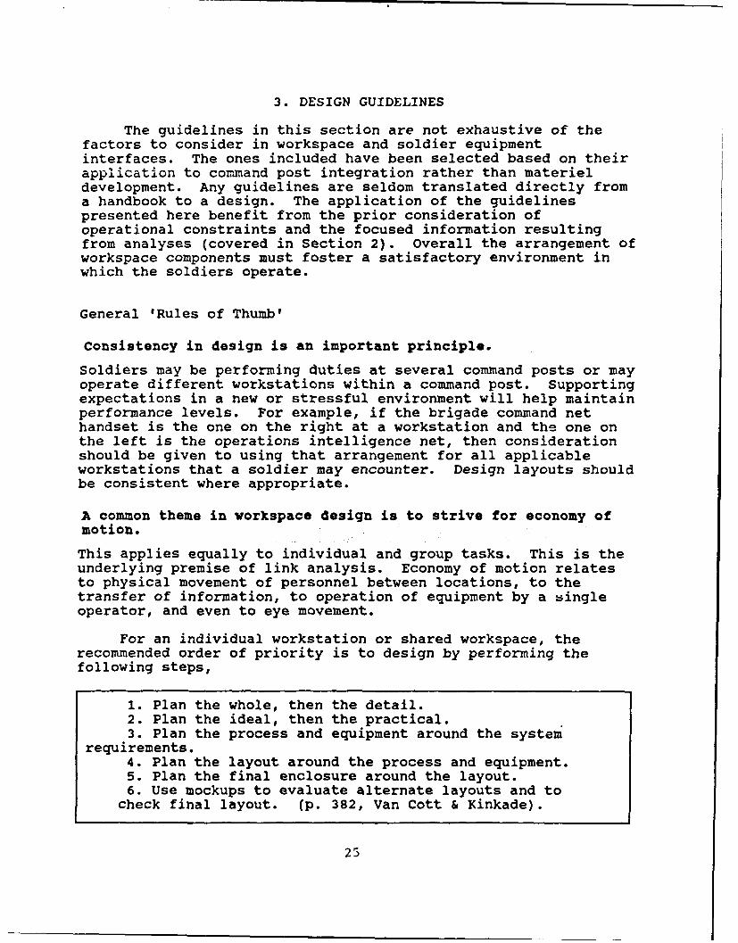
For an individual workstation or shared workspace, therecommended order of priority is to design by performing thefollowing steps,
1. Plan the whole, then the detail.2. Plan the ideal, then the practical.3. Plan the process and equipment around the system
requirements.4. Plan the layout around the process and equipment.5. Plan the final enclosure around the layout.6. Use mockups to evaluate alternate layouts and to
check final layout. (p. 382, Van Cott & Kinkade).
25
3. DESIG GIDELINES
The workspace is a dynamic environment. The designer shouldtry to visualize the use of the workspace over time for criticalfunctions, not as a static arrangement of equipment. Whendealing with conceptual diagrams of workspace arrangement it iseasy to overlook the fact that people are not stationary and thatfunctions may not be fixed in one place.
The SCP designer will have to make tradeoffs among competingfactors in workspace layout. The following criteria are listedin order of rcommended consideration.
1. Primary visual tasks.2. Primary controls associated with primary visual tasks.3. Control and display relationships.4. Sequence of operation (left to right, top to bottom).5. Convenience based on frequency of use.6. Consistency of layouts. (Van Cott & Kinkade, 1972)
Group Workspace
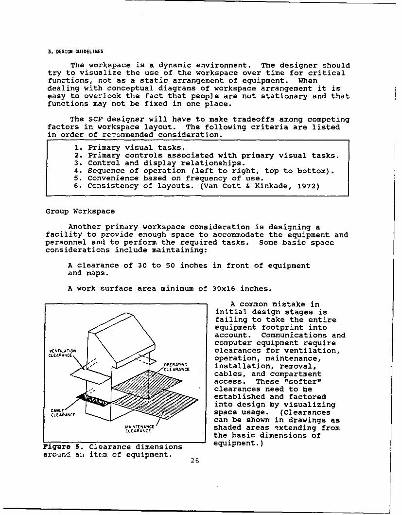
Another primary workspace consideration is designing afacility to provide enough space to accommodate the equipment andpersonnel and to perform the required tasks. Some basic spaceconsiderations include maintaining:
A clearance of 30 to 50 inches in front of equipment
and maps.
A work surface area minimum of 30x16 inches.
A common mistake ininitial design stages isfailing to take the entireequipment footprint intoaccount. Communications andcomputer equipment require
VENTILATION clearances for ventilation,:LeARANCE, operation, maintenance,OPERATING installation, removal,Ccables, and compartment
access. These "softer"clearances need to beestablished and factoredinto design by visualizing
CLEACE space usage. (Clearancescan be shown in drawings asshaded areas extending from
CLEARANCE the basic dimensions ofFigure 5. Clearance dimensions equipment.)
around- a.i item of equipment. 26

GroW orkspece
Any item should be viewed, operated, manipulated, removed orreplaced by a suitably clothed and equipped user with applicable5th to 95th percentile body dimensions. Applicable values basedon anthropometry have been given for various workspace sizingfactors. (Anthropometry is the technology of measuring varioushuman physical traits, such as body size, mobility, andstrength.) It may be useful to know that anthropometry valuesexist for most body dimensions and can be used for determiningspecial limits for clearances, limiting dimensions, andadjustable dimensions. Anthropometric tables are available inMIL-STD-1472, MIL-HDBK-759, and DOD-HDBK-743.
The following numbered paragraphs are direct excerpts fromMIL-STD-1472.
5.7.4 Common working positions. Anthropometric data for thedesign and sizing of workspaces involving standing, sitting,stooping, kneeling and supine positions are presented in TableXIX and illustrated in Figure 29. Suitable allowances shouldbe made for heavy clothing or protective equipment whenrequired. In no case shall clearance dimensions be less thanthe 95th percentile values for men or limiting dimensions bemore than the 5th percentile values for women. [Figure 29 andTable XIX are included as Appendix B in this document.]
5.7.1.3 Work space. Whenever feasible, free floor space of atleast 4 feet shall be provided in front of each console. Forequipment racks that require maintenance, free floor spaceshall be provided in accordance with the following criteria.
5.7.1.3.1 Depth of work area. Clearance from the front of therack to the nearest facing surface or obstacle shall not beless than 1.070 m (42 inches). The minimum space between rowsof cabinets shall be 200 mm (8 inches) greater than the depthof the deepest drawer (equipment).
5.7.1.3.2 Lateral work space. The minimum lateral work spacefor racks having drawers or removable equipment shall be asfollows (measured from the drawers or equipment in theextended position):
a. For racks having drawers or removable items weighingless than 20 kg (44 pounds): 460 mm (18 inches) on one sideand 100 mm (4 inches) on the other.
b. For racks having drawers or removable items weighingover 20 kg (44 pounds): 460 mm (18 inches) on each side.
27

3. DESIGN GUIDELINES
5.7.2 Standing operations
5.7.2.1 Work surface. Work surfaces to support job instructionmanuals, worksheets, etc., shall be 915 +15 mm (36+0.6 inches)above the floor.
5.7.2.2 Displav placement, normal. Visual displays mounted onvertical panels and used in normal equipment operation shallbe placed between 1.040 m (41 inches) and 1.780 m (70 inches)above the standing surface.
5.7.2.3 Display placement, special. Displays requiringprecise and frequent reading shall be placed between 1.270 m(50 inches) and 1.650 m (65 inches) above the standingsurface.
Important dimensions to remember in the
design of any desk or table ate: MINIMUM USEFUL( Working height. WMITNG AREA
® Working width and depth.
) Knee room height and depth.
Kick room.
Figure 6. Work surface and desk dimensions.
28

Grop Workspece
5.7.3 Seated operations [See Figure 6.]
5.7.3.1 Work surface width and depth. A lateral workspace ofat least 760 mm (30 inches) wide and 400 mm (16 inches) deepshall be provided whenever practicable.
5.7.3.2 Work surface height. Desk tops and writing tablesshall be 740 to 790 mm (29 to 31 inches) above the floor.
5.7.3.3 Writing surfaces. Where a writing surface is requiredon equipment consoles, it shall be at least 400 mm (16 inches)deep and should be 610 mm (24 inches) wide, when consistentwith operator reach requirements.
5.7.3.4 Seating.
5.7.3.4.1 Compatibility. Work seating shall provide anadequate supporting framework for the body relative to theactivities that must be carried out. Chairs to be used withsit-down consoles shall be designed to be operationallycnc-patibl e with the console configuration.
5.7.3.5 Knee room. Knee and foot room that equals or exceedsthe following minimum dimensions shall be provided beneathwork surfaces:
a. Height: 640 mm (25 inches)b. Width: 510 mm (20 inches)c. Depth: 460 mm (18 inches).
5.7.3.6 Display placement. normal. Visual displays mounted onvertical panels and used in normal equipment operation shallbe placed in an area between 150 and 1170 mm (6 and 46 inches)above the sitting surface.
5.7.3.7 Display nlacement. special. Indicators that must beread precisely and frequently shall be placed in area between360 and 890 mm (14 and 35 inches) above the sitting surface,and no further from 530 mm (21 inches) laterally from thecenterline.
29

3. DESIGN UIDELINES
d /
, I
Figure 7. Accommodations for dual sit-stand operations.
Where ceiling height permits, consider using drafting-tableor counter work heights (36 inches vs. the typical desk height of30 inches) and display heights to allow both seated (draftingchair) and standing operations (see Figure 7). Dual sit-standcapabilities will allow mobility, when needed and will be adeterrent to postural fatigue (Van Cott & Kinkade, 1972).
Minimize distractions in the group workspace, that may becaused by attention getting signals from nearby blinkingindicator lights or audible signals on radio or computerequipment. For those not directly operating the equipment,shield unnecessary auditory or visual signals. This can be doneby reducing the intensity of the signals, attenuating the travelof the signal, and strategic placement and orientation ofequipment.
Communications
Interpersonal communication is a primary issue in multiplework places. Common work areas promote the flow of informationamong people. Proximity of location fosters communications amongstaff elements. However, with simultaneous tasks beingperformed, common work areas can create unwanted interferencesand distractions. What is an important message to one person or
30

Consi cat ions
group may be noise to others. Link analysis (as described indetail in Section 2) will help determine locations based onpriority of function and the required proximity to produce thedesired frequency and quality of communications among pairs orgroups of staff.
Many of the operations within a command post requiremobility. Communications equipment should not restrict themobility; it should accommodate it. Consideration should begiven to increasing the accessibility of communication input andspeaker devices.
Mobility
Tasks which require the highest mobility (for example,plotting and message passing) need to be allocated sufficientspace, based on the priority of function, and should be centrallylocated to interacting elements. Personnel who are performingthe most important function should stay in place and supportingpersonnel should make any required movement.
Standing permits greater mobility than seated operations,and permits more front-to-rear operating room and greater designlatitude. However, seated operation leads to superiorperformance over prolonged periods. The disadvantages of seatedoperations are the reduced reach envelope and additional spacethat is required for access to seating.
Functions and Links
To ease or speed the flow or interaction of personnelperforming their required jobs, functions can be handled usingthree general rules. These rules apply whether a function inquestion is performed by a single person or by a group ofpersonnel.
Similarity. Similar functions should be located together.
Criticality. Important or critical functions should takedesign priority over lessor functions.
Frequency. Functions which occur most frequently should begiven design priority over less frequent functions.
Unfortunately the principles of similarity, criticality, andfrequency can conflict. For example, posting and updating mapsis a frequent function in a command post. Though it is anecessary function, it is only a source of data, and so many
31

3. DESIGN GUIDELINES
other functions can be construed as more critical. These -lesneed to be weighted to make defendable trade-offs.
Supervision
An obvious consideration of grouping of personnel is therequirement for supervision. Supervisory requirements suggestthat supervisors and their people need to be located fairly closedepending on the frequency and time required for supervision.Severe environments increase the requirements for supervision.For example in Mission Oriented Protective Posture (MOPP) 4clothing requirements for supervision increases to ensure properfluid intake.
Transient Personnel
Command posts require accommodations for transientpersonnel. Transient personnel are those that are not assignedto a command post or are not always there. They can include thecommander, the executive officer, message carriers, subordinatecommanders, etc. Special considerations should be given todetermine what transient personnel will be sharing the workspace.Access and visual clearance need to be provided, and space needsto be provided whenever information must be shared with anotherat a workstation (for example, planning tasks using the MCSdisplay). If possible the design should consider the worst casesituation (most crowded). An example of this might be theoperations briefing in front of the situation map.
Passageways
Command posts must also maintain adequate access and trafficareas. Passageways and aisles are typically open space left inor among tents or shelters to accommodate traffic. Intersectionsshould converge at 90 degrees. Aisles should be kept clear.Aisles should not be located against blank walls because thisunder-utilizes wall space. Blind corners should be avoided.Paths should be located for minimum distance based on thepriority and frequency of function. Aisles should be 54 incheswide for two persons passing (with 44 inches wide the minimum)(see Figure 8). They can be as small as 36 inches wide for oneperson passing and one standing perpendicular (with 30 inches theminimum) (Thomson, 1972). These dimensions are for typical dutyuniform and should be increased for locations where wet and coldweather clothing, MOPP gear, and packs will be worn.
Displays
The following guidelines have been selected to apply to the
32

Displ ays
(44 in MIN) ONE PERSON PASSING
ONE STANDING AGAINST WALL
TWO PERSONS PASSING
Figure 8. Dimensions for passageways and aisles.
Displays
The following guidelines have been selected to apply to theintegration of components, such as a grouping of computers andother equipment and special unit-designed charts. There will notbe much latitude for the SCP designer to alter the computerequipment (but several techniques can be applied to reducefatigue as described in a corresponding section that follows).
Alphanumeric characters, geometric and pictorial symbolsshould not subtend lessthan 16 minutes of visualangle (see Figure 9). Thistranslates to a minimumsymbol height of .09 inches(2.3 mm) for viewingdistances less than 19.7inches (500 mm) and 1.5inches (38 mm) for viewingdistances from 157.4 to315.5 inches (4.0 to 8.0 VISUALm). To estimate theappropriate symbol height OBJECTmultiply the viewingdistance by .0045, or toestimate maximum viewing Figure 9. Illustration of thedistance divide a given meaning of visual angle.symbol height by .0045.
33

3. DESIGN GUIDELINES
(These formulas were derived from 5.5.5.15, MIL-STD-1472. Note:the symbol height for the font type of this paragraph is about.11 inches, which indicates an eye to page viewing distance of nomore than 24 inches.)
It is also important that consistency is maintained acrossworkstations for placement and types of controls and displays.The following paragraphs from 5.2.1.4.1 through .10 are excerptsfrom MIL-STD-1472 on the placement of displays.
5.2.1.4.1 Location. Displays [including maps and charts]should be located and designed so that they may be read to thedegree of accuracy required by personnel in the normaloperating or servicing positions without requiring theoperator to assume an uncomfortable, awkward or unsafeposition.
5.2.1.4.4 Reflection. Displays shall be constructed, arranged,and mounted to prevent reduction of information transfer dueto the reflection of the ambient illumination from the displaycover (e.g., acetate overlay).
5.1.2.4.6 GroupinQ. All displays necessary to support anoperator activity or sequence of activities, shall be groupedtogether.
5.1.2.4.7 Function and semuence. Displays shall be arranged inrelation to one another according to their sequence of use orthe functional relations of the components they represent.They shall be arranged in sequence within functional groups,whenever possible, to pr ;vide a viewing flow from left toright or top to bottom.
5.1.2.4.8 Frequency of use. Displays used most frequentlyshould be grouped together and placed in the optimum visualzone. [The normal line of sight for hu:ians is 15 degreesbelow horizon. Displays should be in a radius of 10 to 15degrees around this line of sight.]
5.1.2.4.9 Importance. Important or critical displays shall belocated in a privileged position in the optimum projectedvisual zone or otherwise highlighted.
5.2.1.4.10 Consistency. The arrangement of displays within asystem shall be consistent in principle from application toapplication, within the limits specified herein.
34

Displays
The orientation of displays also must be taken into account.Every display has optimal viewing angles and distance that theyshould be placed from an observer. Displays should be orientedto encompass the intended group of viewers.
Operators should bestationed so that theirlines of sight to thedisplay form an anglebetween 60 and 90degrees. In no caseshould this angle "
exceed 45 degrees. (p.
27, Benel & Benel, -
1984)
L _ __ -Figure 10. Example of viewing angle.
Also Shurtleff & Wuersch (1979) have developed a techniquefor identifying the appropriate viewing envelope based on symbolSize and brightness contrast ratio. As symbol size andbrightness contrast ratio decrease, accuracy readability ortarget detection drops off sharply. Appropriate viewing areasand distances can be identified for three categories ofcriticality (based on speed and accuracy levels) in command andcontrol centers. (The algorithm and technique are discussedfurther in Benel & Benel.) The geometry of display layout is animportant design element.
Screens Screens
Good GoodViewing ViewingArea Are@
Figure 11. Good viewing area increases with oblique screenpositioning.
The following excerpts on large screen displays are from
MIL-STD-1472.
35

3. DESIG GUIDELINES
5.2.5 LarQe-screen displays.
5.2.5.1 Use. Large-screen displays may be used when:
a. A group of operators frequently refer to the sameinformation and are required to interact as a team, based onthe same information.
b. One or more members of a team of operators must moveabout, yet require frequent referral to information requiredto make decisions, but which they cannot carry with them, ordo not have displayed at their assigned position(s).
c. Space or other constraints preclude the use ofindividual displays for each team member to call u- commonly-used information.
d. It may be desirable to have general informationavailable to persons who should not interrupt on-going groupoperations by looking over the shoulder(s) of individualoperator(s) to see their individual displays.
5.2.5.2 Avoidance. Large-screen displays shall be used onlywhen the spatial and environmental conditions allowsatisfactory observational geometry to insure that allcritical operators have appropriate visual access in terms ofviewing distance, angle and lack of interference fromintervening objects, personnel or ambient lighting.
5.2.5.3 Viewing distance. The display shall not be placedfurther from an observer than will provide appropriateresolution of critical detail presented on the display. Thedisplay shall not be closer to any observer than 1/2 thedisplay width or height, whichever is greater.
5.2.5.4 Physical interruption of view. Large-screen displaysshall not be located with respect to critical observers sothat the view of the display is obscured regularly by personsmoving about--by normal traffic patterns.
When simultaneous displays must be viewed, the goal inworkspace design is to overlap the viewing angles to reduce eye,head, and gross body movement (employing the principle of economyof motion). If two displays are frequently compared, then theyshould be near by. Slightly angling screens towards each otherincreases the good viewing area for both screens (see Figure 11)(Benel & Benel; Fallesen, 1983).
36

Fatigue at Cauter Workstations
Fatigue at Computer Workstations
There are two interrelated sources of fatigue experienced atcomputer workstations. One is posture related due to extendedperiods at a workstation. Another is due to a concentratedvisual effort for long periods. Soldiers operating tacticalcomputers in command posts are especially prone to the physicallystressing effects because of rather stark workplace furnishingsand the long shifts with intense workload. These stresses arelikely to turn up as backaches, neck aches, headaches, burning or"tired" eyes, and potentially as spinal disorders.
The most affected skeletal parts of the body are the neck,back, abdomen, arms and legs (Cakir, Hart & Stewart, 1980).Postural fatigue should not be unexpected, because any posture isharmful if it is maintained for too long a period, and especiallytiring if it is fairly static as computer operation is. Thelayout of the individual computer workspace should do thefollowing:
Permit the individual operator to adjust reading distances(for source documents) and viewing angles.
Encourage changes in working posture, throughout anoperator's shift, (adjustable chairs would help).
Provide an adequate work area next to the computer forworking documents and carefully position them to accommodateviewing and working with the computer screen and sourcematerials.
Ideally furniture for a computer workstation has separatelyadjustable keyboard height, screen height, and chair toaccommodate 5th percentile females to 95th percentile males. Thechair should swivel, be tilt adjustable, and an adjustable orflexing back support. When separately adjustable furniture isnot available the following dimensions have been computed basedon ANSI/HFS 100-1988 (Human Factors Society, 1988) and MIL-STD-1472.1 Seat height
50.0 cm (19.7 inches)Keyboard support height 71.0 cm (28 inches)Top of display height 117.7 cm (46.3 inches)
The seat height is set at the popliteal (back of knee) height for95th percentile male ground troop (MIL-STD-1472). Keyboardsupport height is taken from ANSI/HFS 100-1988. The displayheight is computed so the top of the display falls below thehorizontal line of sight of the 5th percentile female ground
37

3. DESIG GUIDELINES
troop with seat height of 50.0 cm. Because the ANSI/HFS standardrequires that lumbar back support be provided for computeroperation, it is strongly recommended for SCP facilities.
Adequate work area should be provided next to the computerworkstation for source documents and other associated computertask needs. Adequacy will be determined by the specific tasks tobe performed at the workstation. A document working area needsto be integrated into the workstation to minimize awkwardpostures when looking back and forth at the display and whentransitioning from keyboard to hardcopy use.
To reduce visual fatigue, operators' vision deficienciesshould be appropriately corrected for computer use. Eye tocomputer distances are slightly longer than typical close readingand writing, so the range of correction for astigmatism, near-and far-sightedness needs to be taken into account. It isimpractical to lean forward or back to adjust one's sightdistance by moving the upper body and head and still maintain anadequate forearm relationship to the keyboard.
Another way to relieve visual and postural fatigue is toplan for rest cycles or to rotate job duties (among computer andnon-computer jobs) while on shift. Computer operation in acommand post may be very intense over a prolonged period. Astatic working posture (with less than ideal f,,rniture), highvisual demands, and machine pacing of the tasks can combine tocreate fatigue. Shifts for computer operation should not followthe typical 12 hour staff duty shift. Consideration should begiven to trading duty positions with other staff personnel or toplan shorter shifts with occasional breaks. Industrialguidelines set by the National Institute of Occupational Safetyand Health (NIOSH) recommend a fifteen-minute break every twohours of work at a video display terminal with moderate workload(Murray, Moss, Parr, & Cox, 1981). For intensive computer workwith repetitive input or other high workload, a fifteen minutebreak every hour is recommended.
Having the right amount of light will reduce glare andimprove the visibility of computer displays. Refer to the boxfor guidelines on how to reduce glare.
3C

Fatipge at Cqxnter Workstatiors
The light source should not be located within 60 degrees ofthe viewer's central field-of-view. The light should bediffused and distributed evenly over the work area, with theratio between light and dark portions of the work surface notexceeding 7:1. Glare can be minimized by keeping the ambientillumination below 300 lux [28 footcandles] with the color ofartificial light not exceeding 3000 degrees K. The CRT shouldbe positioned at right angles to the light source, not facinga window, with the artificial light source shielded orreflected from the walls. All surfaces adjacent to the CRTshould have a dull matte finish. (p. 23, Benel & Benel,1984).
Storage
Allocation of space for storage can usually be left forlater in design after priority functional requirements have beenmet. Storage cannot be overlooked, however. Space must beprovided for storage of necessary materials used within a commandpost, such as map sheets, message logs, doctrinal publications,printer paper, replacement parts, and safe. Space also needs tobe provided for personnel gear, like combat and protectiveclothing and weapons, that are temporarily stored while in ashelter. This type of storage needs to be provided for transientpersonnel as well as assigned personnel. Operation andmaintenance of technical equipment require special storage asindicated in MIL-STD-1472.
5.7.1.3.4 Storage space. Adequate and suitable space shall beprovided on consoles or immediate work space for the storageof manuals, worksheets, and other materials that are requiredfor use by the operational or maintenance personnel. (MIL-STD-1472)
Maintenance
The design of a command post should foster ease ofmaintenance and repair of equipment items. Several guidelinesespecially relevant to component integration are listed below:
Eliminate, reduce, or simplify maintenance requirementsto reduce workspace design constraints (Rigney, 1977).
Provide space for internal and external accessibilityincluding rear, side, top and bottom access as requiredbj the individual item (MIL-STD-1472).
39

3. DESIGN GUIDELINES
Provide space for temporary placement of requireddisassembly during installation, removal, or internalaccess (e.g., cover removal to access adjustmentcontrols, component replacements) (MIL-STD-1472).
The guidelines on the facing page are taken from MIL-STD-1472 for designing for the maintainer.
Set-up and Tear-down
Considerations for proper cabling and keyed connectors arealso important for rapid connection and removal of equipment. Inaddition to the suggested enhancements identified above, soldiertasks for shelter set-up and tear-down should be specified indetail. A specific sequence of steps should be established forsafe and rapid set-up and tear-down. Time lines can be fairlyeasily set for these operations as well as specific dutiesassigned to personnel. Simultaneous operations or operationsthat must be coordinated among several soldiers or locationsshould receive the closest attention.
Equipment Accessibility
The following are additional guidelines from MIL-STD-1472 onmounting equipment within racks or other units to promoteaccessibility.
5.9.2.1 Stacking avoidance. Parts should be mounted in anorderly array on a "two-dimensional" surface, rather thanstacked one on another (i.e., a lower layer should not supportan upper layer, so subassemblies do not have to be removed toaccess other subassemblies within the equipment).
5.9.2.2 Similar items. Similar items shall utilize a commonmounting design and orientation within the unit. Thismounting design shall preclude interchange of items which arenot functionally interchangeable. Similar items which are notfunctionally interchangeable shall be made distinguishable bylabeling, color coding, marking, etc., to prevent unwantedsubstitution.
5.9.2.3 Delicate items. Components susceptible to maintenanceinduced damage through rough handling, static electricity,abrasion, lack of cleanliness or other such factors shall beclearly identified and guarded from abuse both physically andby procedural requirements.
40

Heintenace
5.9.1.1 Standardization. Standard parts shall be usedwhenever practicable and should meet the human engineeringcriteria herein.
5.9.1.2 Special tools. Special tools shall be used only whencommon hand tools cannot be utilized or when they providesignificant advantage over common hand tools. Special toolsrequired for operational adjustment maintenance should besecurely mounted with the equipment in a readily accessiblelocation.
5.9.1.3 Modular replacement. Equipment should be replaceableas modular packages and shall be configured for removal andreplacement by one person where permitted by structural,functional, and weight limitations.
5.9.1.6 Assembly and disassembly. Equipment shall be capableof being assembled and disassembled in its operationalenvironment by a minimum number of trained personnel wearingclothing appropriate to the operating environment specifiedfor the system maintenance concept.
5.9.1.7 Clothing constraints. Equipment shall be capable ofbeing removed, replaced, and repaired by personnel wearingpersonal and special purpose clothing and equipmentappropriate to the maintenance concept, including NBCprotective clothing in an NBC contaminated environment.
5.9.1.8 Error!proof desian. Provisions to preclude impropermounting and installation shall include:
a. Physical measures to preclude interchange of items ofa same or similar form that are not in fact functionallyinterchangeable.
b. Physical measures to preclude improper mounting ofunits or components.
c. Measures (e.g., coding) to facilitate identificationand interchange of interchangeable items.
d. Measures (e.g., alignment pins) to facilitate propermounting of items.
e. Measures to insure that identification, orientation,and alignment provisions include cables and connectors.
41

3. DESIGN GUIDELINES
The following excerpts from MIL-STD-1472 provide additionalguidelines on designing for accessibility. Additional guidelinesare presented in MIL-STD-1472 on equipment cases, covers,physical openings, hazards, visual access, fasteners, lifting,mounting, conductors, connectors, and other maintenance-relatedissues.
5.9.4 Accessibility.
5.9.4.1 Structural members. Structural members or permanentlyinstalled equipment shall not visually or physically obstructadjustment, servicing, removal or replaceable equipment orother required maintenance tasks. Panels, cases, and coversremoved to access equipment shall have the same accessrequirements as replaceable equipment. Mounting provisionsshall be directly visually, and physically accessible by themaintainers. Unless required by security considerations, nospecial tools shall be required for removal or replacement.
5.9.4.2 Large items. Large items which are difficult to removeshall be so mounted that they will not prevent convenientaccess to other items.
5.9.4.3 Use of tools and test equipment. Check points,adjustment points, test points, cables, connectors, and labelsshall be accessible and visible during maintenance.Sufficient space shall be provided for the use of testequipment and other required tools without difficulty orhazard.
5.9.4.5 Relative accessibility. Mission critical items whichrequire rapid maintenance shall be most accessible. Whenrelative criticality is not a factor, items requiring mostfrequent access shall be most accessible.
42

Envi ornent
Environment
Illumination. Illumination is a common area of complaint incommand posts. Close work over prolonged periods can quicklylead to visual fatigue and reduced vigilance. Improvedillumination can help lessen these effects.
The following light levels (in Footcandles, Ft-C) arerecommended (para 5.8.2, MIL-STD-1472):
Recommended (Ft-C) Minimum (Ft-C)General work areas 70 30Traffic areas 20 10Emergency lighting 3
There should be a capability for dimming work area lights and toadjust the position of lighting to provide sufficient task areaillumination and to reduce glare on map overlays and computerscreens. When several displays are used, for example severalmaps, charts and computer, the lighting shall be balanced acrossdisplays such that any two displays do not differ by more than 33percent (para 5.2.1.2.2, MIL-STD-1472).
Lighting security. Another lighting consideration isdesigning for light discipline or lighting security. Blackoutcurtains are a standard for restricting light emissions fromcommand post shelters and should be provided. Most tents providefor double or triple entry flaps to keep light from shiningoutsIde. Provisions also need to be taken to shield doorways onshelters and vans. A vestibule can be provided where a soldierhas enough room to step into a darkened vestibule, closing thevestibule opening, then entering the lighted shelter. Lightingcan be made more secure by following the CECOM Secure Lightingregulation (CECOM-R 70-59, 1988). Some of these guidelinesinclude the following:
Wavelength restriction. Eliminate energy not used by thehuman eye or otherwise not required by the human operator.
Intensity reduction. The luminance of the light sources mustbe dimmable down to .5 foot-lamberts or less and also becapable of being turned up to full brightness for daytime use.
Viewing angle restriction. Reduce the viewing angle as muchas possible (e.g., light control film and/or rubber hoods).
Indicator lights. Only blue-green, green, and yellowindicator lights may be used on equipments.
43

3. DESIGN GOIDELINES
Temperature. The ambient temperature for mobile personnelenclosures, such as command post shelters, should be maintainedabove 10 degrees C dry bulb temperature (50 degrees F) (para3.3.2, MIL-HDBK-759). Heating systems should not discharge airdirectly on personnel. Air conditioning should be provided ifthe "effective temperature" exceeds 29.5 degrees C (85 degrees F)for detail work during prolonged periods (para 3.2.6, MIL-HDBK-759). "Effective temperature" is a combination of dry-bulbtemperature, humidity, air movement, and clothing. Acceptableranges of "effective temperature" vary according to the level ofactivity. To comply with "effective temperature" limits, drybulb temperature limits may be increased for tasks requiringminimal physical exertion. (Refer to MIL-HDBK-759 for moreinformation on determining appropriate temperatures.)
Ventilation. Ventilation requirements include fresh air andthe movement of air. Paragraph 5.8.1.2 in MIL-STD-1472 providesrequirements for the following:
Rates of introducing ventilation air.Rates of air velocity.Prevention of introducing contaminated air.
Potential contaminants and hazards in command posts come from theexhaust of engines and heaters. Contaminants include aldehydes,carbon monoxide, nitrous oxide, and sulfur dioxide. Fouled aircan cause eye, respiratory, and nausea problems. It is importantto keep the combustion exhausts separated from ventilationintakes.
Auditory environment. The auditory environment in commandposts should be controlled by keeping noise below permittedlevels to permit effective communications.
4.1.1 Total System Noise - Subsystems, sets, groups and units,including such items as air conditioners, heaters, I/O devices(e.g., printers, typewriters), and auxiliary equipment, shallbe selected and integrated in such a manner that the noiseproduced by the entire system does not exceed the requirementsof this standard. (MIL-STD-1474)
For frequent telephone or radio use or frequent directcommunication up to 5 feet, noise should not exceed 65 dB(A)(5.1.1.1, MIL-STD-1477). Since typical conversational speech atfive feet is about 60 dB (Deatherage, 1972), adequate speakervolume and an attentive listener would be required in anenvironment close to this noise limit. For requiredcommunications up to 15 feet, noise should not exceed 55 dB(A)
44

Erwi r nt
(5.8.3.3.3, MIL-STD-1472). Noise can be attenuated by staggeredplacement of reflective surfaces, staggered placement of doors,and corridors, and using sound absorbing surfaces (5.8.3.4.2,MIL-STD-1472).
5.3.8.2.1 Monitoring of speakers. When several channels areto be monitored simultaneously by means of loudspeakers, thespeakers shall be mounted at least 175 mrad (10 degrees) apartin the horizontal plane frontal quadrant, ranging radiallyfrom 45 degrees left to 45 degrees right of the operator'snormal forward facing position. (MIL-STD-1472)
The placement of audio and visual alarms and signals needsto be given consideration in group workplaces so the rightpersonnel will detect and be able to discriminate among varioussignals. The signals must have the proper intensity, duration,and other distinguishing characteristics to pinpoint the warningthat is intended to be conveyed.
To discourage auditory detection by enemy forces, MIL-STD-1474 establishes noise limits (see Table 3 in MIL-STD-1474).When noise is in the neighborhood of 65 dB at 25 meters, thesource can be detected as far away as 2000 meters (depending onweather and site characteristics).
Biomechanical stress. Another important design goal is toreduce biomechanical stress whenever possible. Avoid workspacedesigns that require frequent overhead reach or holding one'shands above the shoulders for prolonged periods (for example, mapboards that are too high). Also avoid prolonged stressingpostures such as forward flexing of the neck and forward reach ofthe shoulder and arm. (These considerations apply to the designor selection of seating and work surface heights and angles.Also refer to the section on computer workstation design.)
Weight limits that have been set for lifting and carryingare generally lower than commonly thought. For female soldiersthe range is from 37 to 44 pounds and for males it is from 56 to87 pounds (5.9.11.3.1., MIL-STD-1472). This is based on astandard cube of 18"x18"x12" with uniform weight distribution.Larger cubes or more frequent carries cause a lowering in themaximum lifting limits.
Consider providing a cushioned surface, such as carpet orrubber mats, for prolonged standing positions. These materialsprovide noise dampening and insulating benefits, as well.
Van enclosures. Paragraph 5.12.7.2 in MIL-STD-1472 setsdesign requirements for vans used as shelters for personnel.
45

3. DESI WIDELIVES
These features should be maintained in the design for the SCPapplication. The ceiling height should not be less than 1.890 m(74.5 inches), including the standing work space over or undercables, lights, or other objects. Steps, stairs, or laddersshould be provided when van floors are more than 460 mm (18inches) above ground level. Access doors should have provisionsfor securing doors in both open and closed positions. Alsoinclinometers should be provided to aid in leveling the van ±2degrees in front to rear and side to side aspects.
Safety
Safety is a major concern in design and is the drivingfactor for many of the design guidelines that have been presentedin previous Sections (for example, discrimination among audiblesignals, minimal illumination levels, adequate maintenanceaccess). Appendix C taken from paragraph 6.1.1, MIL-HDBK 759provides an excellent discussion of the principles of safety asthey relate to human behavior. Some of these principles applyonly to the design of specific pieces of equipment, but mostpertain to the design and operation of SCP. Other safetyguidelines for SCP include the following (adapted from Leeson,1989; Thomson, 1972).
Doors should be easily accessible and sufficient clearanceprovided into the aisle when it is swung open.
Alternate exits should be provided in command post sheltersand vehicles.
Adequate traffic area illumination should be provided, aswell as emergency lighting.
Engine and generator exhausts should be routed away from vanand tent enclosures.
Provisions should be made to secure heavy equipment, such asradios and computers, to prevent shifting or falling onpersonnel during operation and set-up and tear-down.
Cabling should be secured out of the way to preventbreaking, snagging, or tripping.
Inter-vehicular ramps and other connections, such as thoseamong expansible vans (which are elevated about 44 inchesabove the ground) should provide fairly level surfaces fromone shelter to another. Ropes, chains or guardrails can beused to thwart falls from stairs or open platform ends.
46

Safety
Common ground should be established among electricalequipment and vehicles.
Safety and warning labels need to be appropriately displayedand legible.
There needs to be safe access to overhead storage on boththe inside and outside of shelters and vehicles withadequate steps and handholds.
Fuel lines should be appropriately shielded or ruggedizedwithin personnel compartments.
Finally, the designer must be careful that severalinfrequent, low-consequence, or marginal hazards do not combineto add up to major safety problems.
47
4. GUIDELINE IMPLEMENTATION
To integrate and summarize the recommended design approachsome implementation guidance is provided in this Section.
Integrating the Design
In the analytical phase of the design process, the designershould address the following questions:
What are the operational goals and constraints of the commandpost and the force it supports?
What is the single most important thing that this command postdoes that supports the commander?What are the supporting functions that serve to accomplish thismission?What are the tasks that have to be performed to do thisfunction?How are these tasks done, by whom, how often?What is the flow of information and the interaction among staff?
Who will be available to perform in the commpnd post and arethey sufficient to meet the manning and workload requirements?Do they have the proper base of experience and knowledge?What are the common job elements of the functions and tasks?Of these commonalities, what appear as the clusters ofactivities?
At this point, the designer has performed the initialanalyses up to workspace layout. The designer has specified theoperational goals and constraints, has performed a functionalanalysis, and identified a functional flow and flow ofinformation. Available reference materials such as missiontraining plans and doctrinal tactics, techniques, and procedureshave been used. Tasks have been identified along with theirassociated importance by criticality and frequency. The firstlevel link analysis should have been completed to identifypersonnel and functional grouping requirements for sub-elementsof the command post. An initial list of equipment has beenidentified based on baseline TOE needed to perform thosefunctions and the numbers and skills of soldiers have beenestimated and workload has been balanced among the specialtiesand soldiers.
The bulk of the designer's time has been spent ondecomposing the mission, functions, and tasks and putting all ofthat into a logical framework. After this it is time to workwith the physical elements of the design -- the workspacelayout. Here it is appropriate to start with the second level of
49

Talloring the Cuidetines
link analysis to determine personnel and equipment locationswithin the common work area. In the iterations and trade-offs inconstructing alternate conceptual layouts the following questionsh!-huld be addressed:What is the focal point of work within the command post?Is it individual in nature or group in nature?Will the command post house a collection of individualworkplaces?What is the relative importance of group interaction for thefunctions?
For given scenarios, what are the most important functions thatneed to be done to have a favorable effect on commanded orsupported units?What are the associated items of equipment that ought to be nearor centrally located for these most important things?
who is involved in doing these most important things?Who are they?
How can the strong links be fostered and how can possibleconfusion and distractions be lessened?
The recommended design approach requires a substantialinvestment in consideration to the functional requirements andthe range of soldiers that perform the functions. By followingsome of these basic questions in design analyses and applyingthe design guidelines, a better SCP should emerge -- one thathas been designed to fit the soldiers.
Tailoring the Guidelines
The following are examples of 'rules of thumb' that can begenerated from the general guidelines presented in this handbook.These can be used as criteria in generating designs and makingtrade-offs among alternative concepts. These examples are basedon observations of potential problems with previous command postlayouts.
General. Allow for viewing of computer screens and print-outs by other than the primary operator (for example, commander,chief of staff, executive officer).
Allow sufficient aisle space or access space to get to eachworkstation without requiring movement of others.
so

4. JIDELIME IMPLEWMTATION
Optimize the configuration geometry of multiple displaysthat need to be used simultaneously (e.g., unit status charts andsituation maps) by orienting adjacent displays at an angle.
Expansible vans. Locate heavy items of equipment in thecenter of the expansible shelter (alternatively place on lockingcasters or sliding mechanisms to re-locate easily).
Place maps on curbside and roadside walls in sheltercarriers, and allow enough work area for the necessary numbers ofpeople in front of the maps (avoid conflicting work space usagenearby, such as passageways).
Use the three entrances wisely, close off one of them tolimit traffic strategically or to use as additional work spaceagainst the wall. Ensure there are adequate emergency exitsavailable.
M577 and extension tent. Avoid using the M577 ramp as awork area in an elevated platform mode as it blocks M577 accessand creates a potential hazard.
Standardized Integrated Command Post System (SICPS) tent.There is a potential tripping hazard where floor panels overlap(Wettig, 1990). Heavy items, such as table legs and safes can beplaced on these junctions to hold them tightly across theenclosure and securely down. A slipping hazard also exists whensnow, ice, or water are tracked onto the floor (Smith, 1989).
SICPS light sources need to be augmented for most tasks.Two 40 watt fluorescent lights provide less than 30 footcandlesof illumination at typical SICPS work areas (Wettig, 1989).
Computer workstations should be located away from thenatural illumination coming through windows and doors andreflected off nearby walls.
SICPS inteQrated shelter. Placement of equipment should notobstruct use of the secondary access hatch (Leeson, 1989).
Design Assistance
The combat developer need not bear the entire burden ofdesign. He or she should take full advantage of anyopportunities for assistance in this work. The designer can lookto activities that have performed related technical work in pastand ongoing efforts in materiel acquisition programs, such as theStandardized Integrated Command Post System (SICPS), ArmyTactical Command and Control System (ATCCS), and Force Level
51

DesIg Assistance
Control System (FLCS). Technical findings are available for manyof these programs, as well as from other command and controlresearch and development efforts. Some of the information can beobtained through literature searches, but the best resource willbe the technical and operational experts that are familiar with aparticular issue. Human factors practitioners located at TRADOCcenters, Army laboratories, research and development centers,Army Materiel Commands (AMCs), test boards, analysis activities,and evaluation agencies can be contacted for information,guidance, and assistance.
52
5. REFERENCES
Aldrich, T. B., & Szabo, S. M. (1986). A methodology forpredicting crew workload in new weapon systems. InProceedings of the Human Factors Society 30th Annual Meeting,(pp 633-637). Santa Monica, CA: Human Factors Society.
ANSI/HFS 100-1988. (1988). American National Standard for HumanFactors EngineerinQ of Visual Displav Terminal Workstations.Santa Monica, CA: Human Factors Society.
Babbitt, B. A. & Nystrom, C. 0. (1989). Questionnaireconstruction manual. ARI Research Product 89-20. AD A212 365
Bean, T. T., Ottenberg, M. A., Mukherjee, R. K. (1983). Commandand control subordinate system functional analysis: Maneuvercontrol functional segment. MTR-83W00022. McLean, VA: Mitre.
Belenky, G. L., Krueger, G. P., Balkin, T. J., Headley, D. B., &Solick, R. E. (1987). Effects of continuous operations(CONOPS) on soldier and unit performance: Review of theliterature and strategies for sustaining the soldier inCONOPS. Technical Report WRAIR-BB-87-1. Washington, D.C.:Walter Reed Army Institute of Research.
Benel, D. C. R., & Benel, R. A. (1984). Use of group viewingdisplay for SHORAD command and control. US Army HumanEngineering Laboratory Technical Note 8-84. Aberdeen ProvingGround, MD.
Cakir, A., Hart, D. J., & Stewart, T. F. M. (1980). VisualDisplay Terminals. New York: Wiley.
Carter, C. F., Archer, M. A., & Murray, A. E. (1988).Description of selected Army staff functions: Targets forplanning aids. ARI Research Note 88-62. Army ResearchInstitute, Alexandria, Virginia. AD A197 449
CECOM-R 70-59. (1988) Research, Development, and AcquisitionSecure Lighting. Fort Monmouth, NJ: US Army Communications-Electronics Command. (Also draft revision 5, 1 March 1990).
Chapanis, A. (1977). Human factors in systems engineering. In K.B. De Greene (Ed.), Systems Psychology. New York: McGraw-Hill.
Command and Control Directorate, US Army Combined Arms CombatDevelopment Activity. (draft). Objective functionalrequirements for the force level control system at the corps,division, and brigade echelons. Coordinating Draft, January1990.
Deatherage, B. H. (1972). Auditory and other sensory forms of
53

information presentation. In H. P. Van Cott and R. G. Kinkade(Eds.), Human EngineerinQ Guide To Equipment Design.Washington, D.C.: Government Printing office.
DOD-HDBK-743. (1980). Anthropometry of US Military Personnel.Washington, DC: Department of Defense.
Fallesen, J. J. (1983). Workspace layout of an M820 van for airbattle management operations. US Army Human EngineeringLaboratory Technical Note 6-83.
Harris, R., Kaplan, J., Bare, C., Iavecchia, H., Ross, L.,Scolaro, D., & Wright, D. (1989). Human Operator Simulator IVUser's Guide. ARI Research Product 89-19. AD A212 007
Headquarters, Dept. of Army. (draft). Mission training plan forcorps command group and staff. Army Training and EvaluationProgram-MTP No. 100-15.
Headquarters, Dept. of Army. (draft). Mission training plan fordivision command group and staff. Army Training andEvaluation Program-MTP No. 71-100.
Headquarters, Dept. of Army. (1984). Staff organization andoperations. Field Manual 101-5. Washington, DC: Author.
Hendy, K. C. (1989). A model for human-machine-human interactionin workspace layout problems. Human Factors. 21, 5, 593-610.
Hendy, K. C., Berger, J., & Wong, C. C. (1989). Analysis ofDDH280 bridge activity using a computer-aided workspace layoutprogram (LOCATE). DCIEM No. 89-RR-18. Downsview, Ontario:Defence and Civil Institute of Environmental Medicine.
Human Factors Society (1988). American National Standard forHuman Factors Engineering of Visual Display TerminalWorkstations. ANSI/HFS Standard No. 100-1988. Santa Monica,CA.
Jones, E. R. & Grober, D. T. (1962). The failure task analysis.Report 8276. St. Louis, MO: McDonnell Aircraft Corp.
Kjellberg, A. (1977). Sleep deprivation and some aspects ofperformance. I. Problems of arousal changes. Waking andSlee n , .1, 139-143.
Laughery, Sr., K. R. & Laughery, Jr., K. R. (1987). Analytictechniques for function analysis. In G. Salvendy (Ed.),Handbook of Human Factors. New York: Wiley & Sons.
Leeson, B. E. (1989). Technical feasibility test (TFT) of thestandardized integrated command post system (SICPS) integrated
54

shelter. USACSTA-6849. Aberdeen Proving Ground, MD: U. S.Army Combat System Test Activity. AD B134 129
Lysaght, R. J., Hill, S. G., Dick, A. 0., Plamondon, B. D.,Linton, P. M., Wierwille, W. W., Zaklad, A. L., Bittner, Jr.,A. C., Wherry, R. J. (1989). Operator workload: Comprehensivereview and evaluation of operator workload methodologies. ARITechnical Report 851. AD A212 879
Magnavox Electronics Company. (1988). Functional definition ofthe Army Tactical Command and Control System. (4 Volumes).Ft. Wayne, Indiana.
McCracken, J. H. & Aldrich, T. B. (1984). Analysis of selectedLHX mission functions: Implications for operator workload andsystem automation goals. (TNA AS1479-24-84). Fort Rucker,AL: Anacapa Sciences, Inc.
Meister, D. (1985). Behavioral Analysis and Measurement Methods.New York: Wiley & Sons.
MIL-HDBK 759A. (1981). Human Factors Engineering Design for ArmyMateriel. Washington, DC: Department of Defense.
MIL-STD-1472D. (1989)..Human Engineering Design Criteria forMilitary Systems, Equipment and Facilities. Washington, DC:Department of Defense.
MIL-STD-1474B. (1979). Noise Limits for Army Materiel.Washington, DC: Department of Defense.
Ministry of Defence (1989). Interim Defence Standard 00-25 (Part12)/Issue 1. Human Factors for Designers of Equipment.Glasgow.
Modisette, B. R., Michel, R. R., & Stevens, G. W. (1978).Initial strategies for Tactical Operations System (TOS)support for the command and control process: Final Report,Volume 2, Description of TOS functions for division elements.System Development Corp., Santa Monica, California.
Murray, W. E., Moss, 0. E., Parr, W. H., & Cox, C. (1981).Potential health hazards of video display terminals. Pub. 81-189 (NIOSH). Cincinnati, Ohio: US Department of Health andHuman Services.
Myers, L. B., Tijerina, L., & Geddie, J. C. (1987). Proposedmilitary standard for task analysis. US Army HumanEngineering Laboratory Technical Memorandum 13-87.
Rigney, J. W. (1977). Maintainability: Psychological factors indesign. In K. B. De Greene (Ed.), Systems PsycholoQy. New
55

York: McGraw-Hill.
Scheiber, L. B., Bryden, J. M., Hargis, G. F., & Maggelet, T. F.(1986). Information flow requirements and products for eachkey task. ATCCIS Working Paper 10. Institute for DefenseAnalysis, Alexandria, Virginia. (Report SecurityClassification: Confidential)
Shurtleff, D. & Wuersch, W. (1979). Legibility criteria indesign and selection of data displays for group viewing.Proceedings of the Human Factors Society 23rd Annual Meeting,Boston, Mass. 411-414, Santa Monica, CA: Human FactorsSociety.
Smith, C. L. (1990). Production prove-out check test of thestandardized integrated command post system - tent CP (SICPS-TCP). 8-ES-975-SIC-012, Aberdeen Proving Ground, MD: US ArmyTest and Evaluation Command. AD B140 274
Thomson, R. M. (1972). Design of multi-man machine work areas.In H. P. Van Cott and R. G. Kinkade (Eds.), Human EnQineeringGuide To Eauipment Design. Washington, D.C.: GovernmentPrinting Office.
Van Cott, H. P. & Kinkade, R. G. (1972). Human Engineering GuideToEauipment Design. Washington, D.C.: Government PrintingOffice.
Wettig, J. A. (1989). Technical feasibility test (TFT) ofstandardized integrated command post system (SICPS) tentcommand post. USACSTA-6893. Aberdeen Proving Ground, MD: U.S. Army Combat Systems Test Activity. AD B137 912
Woodson, W. E. & Conover, D. W. (1964). Human Engineering Guidefor Ecuipment Designers (2nd ed.). Berkeley, CA: Universityof California Press.
56

APPENDIX A
Excerpts from Army Command and Control System Employment Concept
A-I

ACCS-A-100-00:Kay 1988
3.0 ATCCS ENNTMObliENT
ATCCS automation must fit into and endure a multifaceted environmen:.-ATCCS computers and communications must be employable in all theaters, eachcharacterized by a variety of threat, envirornmental. and operatingconditions. The Army units that the system will support will make up theorganizational environment. The various operational modes in which theseunits will be engaged pose another aspect of the environment.Functionally, ATCCS automation must fit in among a constellation of othersystems belonging to the Army, other U.S. Armed Services, and othernations. Physically, the environment is made up of the battlefieldinstallation settings in which ATCCS component systems vill reside.Additionally, ATCCS computers and communications viii have to operate in ahostile tactical battlefield environment. In this environment, the enemywill try to create conditions intended to degrade operations of command andcontrol personnel, computers, and communicati,ns. Lastly, since ATCCSautomation will handle classified information, security considerationsconstitute another dimension of the environment.
3.1 Orranizational Environment
The Army vill field ATCCS computers and communications throughout theentire force (that is, both the Active Component and the ReserveComponent), as structured according to the Army of Excelrence (Lidy et &l.,1985). Thus, the ATCCS will support the command and control of the numbersof and types of units shown in Table 3-1. Note that the units listedinclude those in the Reserve Component of the force, in addition to theActive Component.
3.2 Oerational Mode SuMMaM-
The Army will employ the ATCCS under potentially all climaticconditions in peacetime and combat environments. Combat environments willrange from low-intensity conflict through mid-intensity conflict toconflicts that include the use of nuclear, biological, and chemicalweapons. At any level of conflict, forces will engage the enemy in anumber of operational missions. Table 3-2 summarizes from FM 100-5Oyeraiaons the expected missions to be encountered by the various Armyforce types (DA, 1986d). Table 3-3 summarizes the environmental conditionsthat the same types of forces may encounter.
The command posts of these forces will displace frequently to avoiddetection and attack. Displacements using vehicles are estimated to takeplace over primary roads 10 percent of the time, secondary roads 70 percentof the time, and cross country 20 percent of the time. About 10 percent ofall displacements will take place under blackout conditions. Actual
A-2

ACCS-Al - 00-001,tuy 1988
TABLE 3-1
U.S. ARMY FORCE STRUCTURE
ea_ LLgb, a a & viatin Total
Corps Total 4 1 0 0 5
Active 4 1 0 0 5Reserve 0 0 0 0 0
Division Total 14 14 0 0 28
Active 10 8 0 0 18Reserve 4 6 0 0 10
Divisional Brigade Total 42 42 0 28 112
Active 30 24 0 18 72Reserve 12 18 0 10 40
Separate Brigade/ArmoredCavalry Regiment Total 10 "12 7 S 37Active 3 2 3 0 8
Reserve 7 10 4 a 29
Divisional Battalion Total 140 126 28 0 294
Active 100 72 18 0 190Reserve 40 54 10 0 104
Separate Brigade BattalionTotal 30 36 12 0 78
Active 3 6 9 0 18Reserve 27 30 3 0 60
Source: Lidy, 1985.
Notes: Active divisions may include 1 roundout brigade or battali6n of theReserve Component; there are .3 maneuver brigades and 1 combat brigadeattack aviation/combat aviation brigade per division; and there are 10maneuver battalions per heavy division, 9 per light livision. and 3per separate brigade.
A-3

ACCS-A1- 100-001May 1988
TABLE 3-2ISSIONS PUR.FORMED BY TACTICAL FORCES
Division
Offensive OperationsMovement To Contact N N N N N N N NHasty Attack N N N N N N N NDeliberate Attack N H N N N N N NExploitation N N N N N N N NPursuit N N N V N N N N
Defensive OperationsDefense N N N N N N N NCounter/Spoiling Attack N N N N N N N NRetrograde N N N N N N N N
Delay N N N N N N N NWithdrawal N N N N N N N N
Defense and Breakout of N N N N N N N NEncircled Forces
Rear Area Protection N N N N N N N N
Other OperationsReconnaissance in Force N/A N/A L L N/A L L LDemonstration L L L L N/A L L LRaid N/A N/A L L N/A L L LFeint L L L L N/A L L LRelief To Continue Attack N N N N N N N NRelief To Continue Defense N N N N N N N NStabilization Operations N L L L L M N MReserve N N N N N N N N
Key: AA Air Assault K Medium ProbabilityAbn Airborne of AssignmentACR Armored Cavalry Regiment Mech MechanizedArm Armored Mtz MotorizedL Lov Probability N Normal Mission
of Assignment N/A Not ApplicableLI Light Infantry Sep Separate
Source: DA, I986d .
A- 4

ACCS-AI-100-001May 1988
TABLE 3-2
KISSIONS PEMPORMED BY TACTICAL FORCES (Concludd)
Offensive Operationsmovement To Contact N N
Ha'sty Attack N 14 N
Deliberate Attack N N N
Exploit-ciOn N N
Pursuit N N N
Defensive Operations L N N N
Defense LNCounter/Spoilifng Attack
Retrograde N N N
Delay VVWithdrawal L N N
Defense and Breakout of N N
Encircled Forces
Rear Area Pro*tection N N N
Other Operations LReconnaissance in Force
L
Deonstration L L L
Raid 14 L L
Feint N L L N
Relief To Continue Attack L I
Relief To Continue Defense L N N
Stabilization Operations L L L N
Reserve NN N
A- 5

ACCS-Al- 100-001May 1988
TABLE 3-3CONDITIONS ENCOUNTERED BY TACTICAL FORCES
CDivisionOperational Conditions 14 t ar Am shn Aa LI
Combat in Urbar, Terrain N L-M L L L N/A N NDesert Warfare L N N N L L-H L XJungle Warfare N L L L L L-M L XMountain Warfare N L L L L L N XWinter Warfare N N N N N N N NRiver Crossings N N N N N N N NNBC Warfare N N N N N N L NAmphibious Operations N L N/A N/A N/A N/A N N/AAirborne/Airmobile N N/A N/A N/A N N L N/A
grigage/ e iment.
Operational Conditions Ze. Arm Se Me h Se2 LT
Combat in Urban Terrain L L L NDesert Warfare N L L LJungle Warfare L L L NMountain Warfare N/A L L NWinter Warfare N N N NRiver Crossings N N N NNBC Warfare N N N NAmphibious Operations N/A N/A.. N/A NAirborne/Airmobile N/A N/A N/A N/A
Key: AA Air Assault M Medium ProbabilityAbn Airborne of AssignmentACR Armo-'-d Cavalry Regiment Mech MechanizedArm Armored MitZ MotorizedL Low Probability N Normal Mission
of Assignment N/A Not ApplicableLI Light Infantry Sep Separate
Source: DA, 1986 d .
A-6

ACCS -Al -100-001May 1988
percentages will vary according to theater and mission. Table 3-4 displaysrepresentative command post and facility mobility characteristics forvarious echelons and includes displacement frequencies, distances, andtimes. These command posts and facilities will displace by section.requiring rhe remaining section or designated replacement command post toexecute the functions of the displacing command post temporarily.
Army forces will use the ATCCS for peacetime in-garrison support,during times of crisis leading up to war, and In full-scale war operations.In each of these modes, patterns of use will vary.
3.2.1 WriUse
The Army is designing ATCCS automation first and foremost to supportthe command and control required to achieve an assigned mission underwartime conditions. In general, ATCCS systems will support all classes ofusers with the applications support discussed in succeeding sections. Whena unit is placed in reserve. ATCCS automation usage will be somewhatdifferent: ATCCS systems will monitor the situation with a view primarilytowards supporting contingency planning by the co=ander and his staff. Iftime permits, individual training and limited staff training will beconducted to educate replacement personnel.
In a wartime environment, uits engaged In combat will use the ATCCSautomation on a 24-hour basis under wartime conditions every day of theyear. ATCCS automation functions must meet this usage requirement despitescheduled maintenance, displacement, or destruction due to enemy action.Actual system loadIng, however, will vary according to the tempo of battle.For example, if night combat operations are infrequent, ATCCS loadingduring the night may consist primarily of combat service supportinformation processing and information processing in support of preparatoryefforts for the next day's combat operations. ATCCS will use primarilytactical communications and tactical power supplies to support itsoperations. Similarly, ATCCS computers and communications generally willbe used in both mounted and dismounted modes with frequent displacements.Finally, depending upon the theater and mission, ATCCS will support a fullrange of joint and combined interfaces.
3.2.2 Peacetimt Use
While primarily intended for use during combat, portions of ATCCSautomation will be used in support of peacetime garrison operations. Theuse of ATCCS automation during peacetime will permit its operators tobecome very familiar with its operations, thereby making wartime use thatmuch easier. Selected Combat Service Support and Intelligence/ElectronicWarfare systems will be used to support day-to-day administration,logistics, maintenance, and intelligence analysis operations, respectively.
A-7

ACCS-A1-100-O01May 198B
TABLE 3-4R.EPRESLAT:VE MOBILITY CHARACTERISTICS OF
COK*.AA POSTS AND FACILITIES
Breakdovn/ Travel StandbyDvell Setup Distance Tie at Tim* perTime Time Moved 20 ka/hr 24 hours
Echelon (hours) (minutes) (kilometers) (minutes) (hours)
Corps 6-26 80-90 30-70 90-210 6.5-13
Division 2-24 6/60 20-60 60-180 5-16
Brigade/ 1.8 3-6/30 10-50 30-150 7-17.5Regiment
Batzalion/ 1-4 3-6/30 10-30 30-90 7.5-16Squadron
Company/ 1 3-6 10 30 0Troop
Source: CACDA, 1987b.
A-8
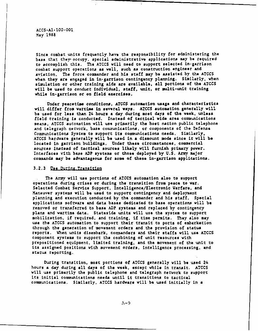
ACCS-A1- 100-001May 1988
Since combat units frequently have the responsibility for administering thebase that they occupy, special administrative applications may be requiredto accomplish this. The ATCCS vill need to support selected in-garrisoncombat support operations as veil, such as construction engineer andaviation. The force commander and his staff may be assisted by the ATCCSwhen they are engaged in in-garrison contingency planning. Similarly, whensimulation or other trainlng aids are available. all portions of the ATCCSvill be used to conduct individual, staff, unit, or multi-unit trainingwhile in-garrison or on field exercises.
Under peacetime conditions, ATCCS automation usage and characteristicswill differ from wartime in several ways. ATCCS automation generally villbe used for less than 24 hours a day during most days of the week, unlessfield training is conducted. Instead of tactical wide area communicationsmeans, ATCCS automation will use primarily the host nation public telephoneand telegraph nevork, base comnnications. or components of the DefenseCommunications System to support its communications needs. Similarly,ATCCS hardware generally will be used in a dismount mode since it will belocated in garrison buildings. Under these circumstances, coercialsources instead of tactical sources likely will furnish primary power.Interfaces vith base AD? systems or those deployed by U.S. Army majorco-maznds may be advantageous for some of these in-garrison applications.
3.2.3 Use During Transition
The Army will use portions of ATCCS automation also to supportoperations during crises or during the transition from peace to war.Selected Combat Service Support, Intelligence/Electronic arfare, and?aneuver systems will be used to support contingency and deploymentplanning and execution conducted by the comander and his staff. Specialapplications software and data bases dedicated to base operations will beremoved or transferred to base AD? systems and replaced by contingencyplans and wartime data. Stateside units will use the system to supportmobilization, if required, and training, if time permits. They also mayuse the ATCCS automation to support their transit to ports of embarkationthrough the generation of movement orders and the provision of statusreports. When units disembark, commanders and their staffs will use ATCCScomponent systems to support the combining of unit resources withprepositioned equipment, limited training, and the movement of the unit toits assigned positions with movement orders, intelligence processing, andstatus reporting.
During transition, most portions of ATCCS generally will be used 24hours a day during all days of the week, except while in transit. ATCCSwill use primarily the public telephone and telegraph network to supportits initial communications needs until it transitions to tacticalcommunications. Similarly, ATCCS hardware will be used initially in a
A-9
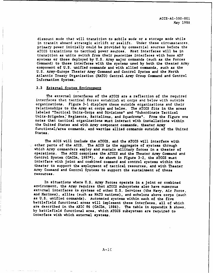
ACCS-Al-100-O01MAy 1988
dismount mode that will transition to mobile mode or a storage mode whilein transit aboard strategic airlift or sealift. Under these circumstances,primary power initially could be provided by com mercial sources before theATCCS transitions to tactical power sources. Most interfaces will be intransition as units switch from their peacetime interfaces with base ADPsystems or those deployed by U.S. Army major commanda (such as the ForcesCommand) to those interfaces with the systems used by both the theater Armycomponent of U.S. unified commndls and with allied com2.ands, such as the
U.S. Army-Europe Theater Army Command and Control System and the NorthAtlantic Treaty Organization (NATO) Central Army Group Command and ControlInformation System.
3.3 External System Environment
The external interfaces of the ATCCS are a reflection of the requiredinterfaces that tactical forces establish at corps and below with outsideorganizations. Figure 3-1 displays these outside organizations and theirrelationships to the Army at corps and below. The ATCCS fits in the areaslabeled "Tactical Units-Corps and Divisions* and 'Subordinate TacticalUnits-Brigades: Regiments, Battalions, and Squadrons'. From the figure onenotes that tactical organizations must interact with installations withinthe United States and with Army component communds, theater Armyfunctional/area commands, and wartime allied commands outside of the UnitedStates.
The ACCS will include the ATCCS, and the ATCCS will interface withother parts of the ACCS. The ACCS is the aggregate of systems throughwhich Army commanders employ and sustain military forces in a theater ofoperations. The ACCS comprises the ATCCS and the Theater Army Command andControl System (CACDA, 1987a). As shown in Figure 3-2, the ATCCS mustinterface with joint and combined command and control systems within thetheater to support the employment of tactical resources, and with TheaterArmy Cowmand and Control Systems to support the sustainment of theseresources.
In situations where U.S. Army Forces operate in a joint or combinedenvironment, the Army requires that ATCCS subsystems also have numerousexti.rnal interfaces to systems of other U.S. Services (the Navy, Air Force,and Marines), allies (such as NATO nations), and echelons above corps (suchas U.S. unified commands). Automated systems within each of the fivebattlefield functional areas will implement these interfaces, all of whichare described in the ABIC 86 (CACDA, 1986). The table in Appendix B shows,by battlefield functional area, which ATCCS subsystems are required tointerface with which external systems.
A-iC

ACCS-AI-100-001K'ay 1988
3.4 Installation SettIn s
ATCCS computers and communications vill support users located innumerous command posts and facilities, including tactical operationscenters, command posts, fire direction centers, weapon or sensor controlfacilities, and unit headquarters at all echelons. These facilities willrange in size from that of & heavy corps main command post (composed ofnmaerous shelters dispersed over an area from 2 to 20 square kilometers) toa forward observation post (composed of a tvo-man tean carrying all oftheir gear). The composition of these locations may include any of thefollowing installation settings:
1. Tracked vehicles
2. Wheeled vehicles
3. Light vehicles
4. Tents
5. Expandible vans
6. Aircraft, such as the BLACK HAWK utility helicopter
7. Dismounted
8. Ground mounted
9. Buildings
3.5 Threat Environment
Although the U.S. Army most likely will engage enemy forces in lowintensity conflict, threat forces of the Warsaw Pact represent the mostserious opposition likely to face the U.S. Army (CACDA, 1987a). Thesethreat forces place a high priority on the disruption or destruction oftheir enemy's command, control, communications. and intelligence systems.The Warsaw Pact forces likely vill apply a variety of resources againstU.S. Army systems, including lethal and nonlethal attack means employed todeceive, deny, degrade, and destroy portions of the ATCCS. The Armyexpects that this enemy will attack ATCCS shelters and command centers withconventional munitions. electronic warfare, chemical and biological agents,directed energy weapons, nuclear weapons, airborne/airmobile forces, andunconventional or special operations forces.
A-11

APPENDIX B
Selected Anthropometric Data for US Army Soldiers
B-I

to AMR ~ qO t2. a 1 At
w W---
gz 4. a - - u - .t; I "t N M 2-3 0E 0 z V x a -q WC.
z u
w FE 3 , A
Z- -0 0R3~0 z ZO - H--
t- 95 - tCc0c
Jj-
z ML 2- m
a ma
'V,-i z gO, § -9 5 Z
daB- I4

gal; 3 a3 lot2
Omn Ra; aa~ 1"r
r 'm"1 I m 3161f 6
lit-mn 2~c
I Ic* p~ W3
I- ~ ~ ~ ~ ~ ~- 3 1 0 ; 4S~.q ~ *

NM M4 W v!
b02
a. 4 2
20. 4P =U
& u 00 -AR 2 MO
Z.-aa a W
0 w 2q ____q_>_P.
'U Z~
-~~$ U~. hhIZf- -
do 4 a:
0 ~ ~~~ L0; M; R--
IU 9
9-
~ KR 5B-4K

z~ ~ 1
IM 2Sw 00 xM
F 5 00o
10- c-cc
-~ 0-Z ax
ZW24
0~ 94 o
~~12
I C0 .~~~~ bi CC__ _ _ _ _ _ -* _ _ _ _ _ _ _ _oe 4c W, z
-'n-
ooU M
u a40 0 X 41 am~
z 0 q 9= 44
Z A.
0" *
~c
B- a

a'A2e x a
MW 0,l ZO U-
NJw O~zw e
Sm 0 wU& tv
Ral
0
Z i-
aC C.
0, ImL
0 0 094 *-6

APPENDIX C
Safety Excerpts from MIL-HDBK-759
C-1

MIL-HDBK-759A
30 June 1981
SECTION 6
SAFETY
6.1 General. Safety is always an important consideration. In evaluat-ing equipme9nt's safety-characteristics, some of the areas which must bereviewed are:
(a) Failure modes and hazardous effects.
(b) Electrical and electronic safety factors.
(c) Mechanical safety factors, Including hydraulics and pneumatics.
(d) Toxicity.
(e) Radiation.
6.1.1 Principles of Human Behavior Related to Safety. There are princi-ples about human behavior that can help designers design safe equipment.The principles below are based on how people actually use equipment inthe field, and on what actually does happen to that equipment. Theseprinciples give at least a partial answer to why people make errors,misuse equipnent, and do other unsafe things. Armed with such knowledgeof why people err, the designer can avoid many rather subtle temptationsthat give users opportunities to take chances.
Principle 1: If the equipment provided is insufficient or inade-quate, users will modify it, or Improvise, so they can get the job done.Improvised equipment leads to improvised procedures and, often, tohazards.
Principle 2: Procedures should be definite and comprehensive.Some users need little encouragement to discard procedures and do whatthey please, which Is often the wrong thing to do.
Principle 3: People often feel that "it can't happen here." Theyassume that, if someone gets hurt (or damages equipment) by disregardinginstrustions, it will be someone else in some other place. Becausepeople feel safer than they are, procedures must be as nearly foolproofas possible. Pnd since procedures, in turn, are shaped by the equipmentitself, the equipment design must be structured so it encourages safeuse allowing a minimu, of opportunity for operators to use it unsafely.
Principle 4: Once a safety problem has arisen, taking correctiveaction does not necessarily eliminate it. The correction may not besufficient, or may not be appropriate, or may even fail to attack theproblem's cause. If so, the problem may reappear elsewhere or in someother way. Corrective actions should always be followed up to verifythat they have really solved the problem.
C-2

MIL-HDBK-759A30 June 1981
Principle 5: Not all safety problems can be anticipated from studyingconcepts and blueprints. Thorough safety analysis requires realistictests with mockups and prctotypes. No matter how simple and foolproofa concept looks on paper, try it before finalizing the design.
Principle 6: If the equipment is designed so it dces not operateas the user's expectancies and stereotypes lead him to think it will, hewill eventually make mistakes.
Principle 7: If unsafe possibilities are designed into the equipment,no warning note in a technical manual can eliminate thenm completely.Warning notes do have a limited, supplementary value in making mishaps lessprobable. Powever, many users may not have read them, or may not rememberthem, or may not even know where to find them. Warning notes do notprevent safety problems.
Principle E: Accidents are so unreal to some people that they do notappreciate how careless performance can cause accidents. Before theseindividuals take their assignment seriously, and do it thoroughlyand carefully, they must actually see equipment damaged or people injured.
Principle 9: Equipment sh, uld be designed so it is inherently safeto use, rather than relying on special safety training to prevent accidents.N(ot all users get such training, even when it is "required." Someusers will kave had outdated training, or related training, or catch-as-catch-can training.
Principle 10: Equipment users tend to be unimaginative; they donot visualize the consequences of unsafe acts. These people only realizea practice is dangerous after they have seen someone get hurt.
Principle 11: Certain individuals seemingly prefer to work underhazardous conditions, as if their bravery makes the job mcre important.
Principle 12: Negativistic people may be more likely to do sorethlrgbecause they have been told not to do it. Tell such people "don't,"and regardless of personal risk, they do it. Instructions, like warningnotes, are not enough to Insure operators will work safely.
Principle 13: Some operators will try to use equipment in incorrectand unintended ways. Designcrs should consider the possibilities forerrors--listing the possible mistakes the operator can make, and theirconsequences--end try to design equipment so incorrect use will do aslittle harm as possible.
Principle 14: Some accidents occur because technicians cannot (ordo not) identify parts correctly. Whenever the user may injure himselfor damage a part because he does not know what it is, designers shouldprovide coriplete, legible, understandable identification.
C-3

MIL-HDBK-759A30 June 1981
Principle 15: All designs require compromises, tut every effortshould be made to minimize conditions which predispcse to accidents.If uncesirable conditions are tolerated without making a real effortto improve them, they often seem to multiply and interact to produceserious safety problems.
Principle 16: Equipment should be designed so it can be usedsafely without undue buisarce. If the procedures for safe operationseem needlessly difficult or burdensome, people tend to avoid doingwhat seems unnecessary. Idcally, equipment should be designed so itis easier to use it safely then to use it unsafely.
Principle 17: Designers must anticipate that operators do makemistakes, and assure that these inevitable mistakes are not likely toinjure personnel or damage the equipment. For example, users must begiven at least some on-the-job training with operational equipment;these partially trained personnel must be expected to make errors.
Principle 18: The designer must understand all of the requirementshis equipment has to satisfy; only by comprehending these requirementscan he assure that the equipment will meet them.
Principle 19: The operator's care in using and maintaining Itemstends to be related to their complexity and cost. People are most carefulof complicated, expensive items. Conversely, operators tend to neglectsimple, inexpensive items because they seem relatively unimportant.
Principle 20: People must be protected from themselves. Sinceworkers often neglect their own safety, each supervisor must takeresponsibility for certain areas of personnel and equipment safety,and particularly for unwise short-cuts and variations from the pre-scribed procedures.
Principle 21: Abbreviated checklists tend 6o cause mistakes.Checklists may be useful if the personnel are very well trained.However, less knowledgeable technicians may not go beyond the check-list when working in unfamiliar Lreas. Rather than refer to thedetailed Job procedures, they tend to experiment or fill in the gapsby guessing.
Principle 22: The equipment's reputation among users can bevery impcrtant, because it may affect the way they use it ard service it.Even rumors that equipment is difficult or hazardous to use can com-pound and magnify the basic difficulty.
C-4

MIL-HDBK-759A30 June 1981
Principle 23: Ease of use or maintenance affects the equiprent's
reliatility. If items are difficult to maintain, technicians will
probably not keep them in good operating condition, so they will nct be
ready for use when needed. If equipment is difficult to use, operators
will substitute other equipment when they can.
Principle 24: Equipme-nt is particularly susceptible to misuse if
crew members must conrunicate with each other to use it. Fecple seldomr
realize comunications are inadequate until they make mistakes, and
sorretimes not even then.
Principle 25: In summary, the designer should remerber that most
safety problems in operational equipment arise not from defects in the
equiprent, but because people use it improperly. Realistically, we must
expect that this improper use will continue in the future. Therefore
designers must strive even harder to anticipate how their equipment
right be misused, and to design so misuse becomes unlikely and its
effects are not catastrophic. It is obviously much more effective to
design to prevent misuse, rather than attempting to reduce safety
hazards from manufactured equipment.
C-5