standardization and indigenisation of metro railways
TRANSCRIPT

GOVERNMENT OF INDIA
MINISTRY OF URBAN DEVELOPMENT
REPORT OF THE COMMITTEE
ON
STANDARDIZATION AND INDIGENISATION
OF
METRO RAILWAYS, SYSTEMS
AND SUB-SYSTEMS
NOVEMBER 2013


BASE PAPER ON STANDARDIZATION AND INDIGENISATION OF METRO RAILWAYS, SYSTEMS AND SUB-SYSTEMS
1
CONTENTS
1.0 BASE PAPER ............................................................................................................................. 2
1.1 INTRODUCTION ..................................................................................................................... 2
1.2 STANDARDIZATION .............................................................................................................. 2
1.3 INDIGENIZATION ................................................................................................................... 7
2.0 ROLLING STOCK .................................................................................................................... 11
2.1 NOISE AND OSCILLATION LEVEL .................................................................................... 11
2.2 EMERGENCY EVACUATION SYSTEM .............................................................................. 13
2.3 COUPLING ARRANGEMENT .............................................................................................. 14
2.4 PERCENTAGE MOTORIZATION, ACCELERATION / DECELERATION / JERK RATE, POWER TO WEIGHT RATIO ........................................................................................................... 14
2.5 ELIGIBILITY CRITERIA ....................................................................................................... 16
2.6 CONTROL & COMMUNICATION PROTOCOL ................................................................... 17
2.7 DRIVERLESS TRAIN OPERATION ..................................................................................... 18
2.8 INDIGENIZATION ................................................................................................................. 18
3.0 POWER SUPPLY AND TRACTION SYSTEM ......................................................................... 20
3.1 TRACTION SYSTEM ............................................................................................................ 20
4.0 SIGNALLING SYSTEM ............................................................................................................ 28
4.1 INTRODUCTION ................................................................................................................... 28
4.2 SUMMARY OF CONCLUSIONS .......................................................................................... 28
4.3 RECOMMENDATIONS ......................................................................................................... 31
5.0 OPERATION AND MAINTENANCE ........................................................................................ 33
5.1 KEY FINDINGS ..................................................................................................................... 33
5.2 RECOMMENDATIONS FOR O&M....................................................................................... 34
5.3 SCOPE FOR FURTHER STUDIES ...................................................................................... 36
6.0 AUTOMATIC FARE COLLECTION SYSTEM ......................................................................... 38
6.1 CONSTRAINTS IN PROCESS OF INDIGENOUS DEVELOPMENT .................................. 38
6.2 SECURITY ASPECTS .......................................................................................................... 38
6.3 RECOMMENDATIONS AND WAY FORWARD FOR FASTER LOCAL CAPABILITY / CAPACITY BUILDING ..................................................................................................................... 41
7.0 TRACK STRUCTURE / BRIDGE / TUNNELS ......................................................................... 42
7.1 INTRODUCTION ................................................................................................................... 42
7.2 TERMS OF REFERENCE .................................................................................................... 42
7.3 BMRCL COMMENTS AND UPDATED AGENDA BY DMRC ............................................. 42

BASE PAPER ON STANDARDIZATION AND INDIGENISATION OF METRO RAILWAYS, SYSTEMS AND SUB-SYSTEMS
2
1.0 BASE PAPER 1.1 INTRODUCTION
Towards achieving cost optimization strategies for metro rail systems, Ministry of Urban Development constituted a Base Paper Committee). Following couple of meetings of theCommittee on May 29, 2012 and June 07, 2012, certain issues regarding standardization and indigenization of metro rail systems were deliberated. The following paras bring out the key issues deliberated and agreed by the Committee members. Annexure A contains the details of the members of the Base Paper Committee as well as members of various sub-committees.
1.2 STANDARDIZATION 1.2.1 Metro Planning 1.2.1.1 Categorization of Transit System into three categories viz. Light, Medium and Heavy
systems was agreed with traffic capacities (PHPDT) as under: • Light: 15000 to 35000 PHPDT • Medium: 30000 to 60000 PHPDT • Heavy: 55000 and above PHPDT It was agreed that planning shall be performed by carrying out traffic studies for ultimate horizon year with 25 years or more perspective, if city’s development plans are available.
1.2.1.2 Train consist could be 3-car, 4-car, 6-car, 8-car etc. as per requirement of a particular city and powering could be 50% or more (67%). Note:Lately there have been observations that 2- and 9-car train consist may also be added and motorization more than 67% (e.g. 75% and 100%) could also be allowed.
1.2.1.3 Passenger Density in Coaches It was agreed that 6 pax/m2 can be considered for the purpose of traffic planning. While 8 pax/m2 for the purpose of propulsion equipment / HVAC sizing and 10 pax/m2 for structural strength of rolling stock can be considered.
1.2.1.4 Emergency Evacuation Front and side evacuation is possible. DMRC has preference for front evacuation as it more controlled and considered safer in practice. DMRC is member of NOVA (group of 15 medium size metros around the world) and a study report by them favours front evacuation. BMRCL preferred side evacuation, as front evacuation would require power off of the third rail for safety reasons. Worldwide, both systems are adopted including front evacuation in 750V dc third rail system, e.g. Kolkata metro front evacuation with 750V dc third rail. For the present, it was agreed that both side and front evacuation can be adopted by metros depending on their circumstances and preferences. It was further agreed that a committee to be appointed for studying the matter further. Note: The task was entrusted to Rolling Stock Sub-committee and that sub-committee has recommended preference for front evacuation – refer to Para 2.2 of the report.

BASE PAPER ON STANDARDIZATION AND INDIGENISATION OF METRO RAILWAYS, SYSTEMS AND SUB-SYSTEMS
3
1.2.1.5 Environmental / Noise Issue
In the meeting of the Base Paper Committee chaired by Secretary MOUD it was agreed that an expert group / committee can be constituted for studying the acceptable noise levels generated by rolling stock and track particularly in sharp curves. Currently the specifications of rolling stock and Trackwork carry noise level criteria separately with divided responsibilities. There is a need for a holistic approach in this regard. Note: The task was entrusted to Rolling Stock Sub-committee and the recommendation of sub-committee, at Para 2.1, may be referred to in this regard.
1.2.1.6 R&D capability is essential for indigenization of metro system / rail system. The following “soft capabilities” are suggested to be considered for efforts and funding, may be by roping in some of the IITs/NITs as centre of excellence: • Traction power simulation tool • SES Analysis for tunnel ventilation • EMC studies • Rail wheel interaction tools • Current collection simulation tools • Track stability analysis tools • Rail-structure interaction analysis tools • Train simulation capability • Station evacuation simulation • Train entraining / detraining simulation • Multi-modal fare system software • Noise & vibration study tools In the meeting held on Aug 07, 2012 chaired by Secretary MOUD, sub-committee consisting of conveners of other sub-committees as members with Shri IC Sharma (NPM/PMU/SUTP) as convener was nominated. Experts / members from institutes such as IITs / NITs etc. as well as other professionals can be co-opted.
1.2.2 Rolling Stock
1.2.2.1 Rolling Stock Dimensions It was agreed that instead of freezing particular numbers, flexibility shall be provided. The following dimensions / range for typical MRTS were agreed: Length: 20 to 22m Width: 2.7/2.74m, 2.88/2.9m, 3.15/3.2m Height: 3.8m to 4.05m The choice of wider coaches of 3.6/3.66m dimensions were discussed and the members were of the opinion that wider coaches for transit applications may not be suitable in view of increased AC capacities, problems in passenger evacuation, increased size of tunnel & tunnel fans (in underground system) and more importantly this not being a ‘standard’ size as of now, may cost more for developmental efforts. There is a case of further analysis of this size of coaches and idle running during off peak period. However, wider coaches could be thought of for RRTS (Regional Rail Transport System) / MRRTS (Metro-cum-Regional Rail Transit System) system including for elevated and underground systems. Note: There have been observations regarding car dimensions, as under:

BASE PAPER ON STANDARDIZATION AND INDIGENISATION OF METRO RAILWAYS, SYSTEMS AND SUB-SYSTEMS
4
• Car length upto 26m may be considered (China Guangzhou has 26m cars)
• The car width aspects need to be relooked and a critical analysis of car width of
3.3, 3.4 ... 3.6m need to be performed. There are opinions that AC capacities for wider cars are not a constraint. It is stated that 3.6m wide cars are in operation even on Standard Gauge tracks in Denmark.
• In Indian conditions, the minimum car width shall be 3.2m
• The word “standard size” of cars has been often used by some metros, which need to be critically looked into.
Such issues may need further deliberations
1.2.2.2 Acceleration / Deceleration For MRTS applications, the following ranges were agreed as a way forward: • Acceleration: 0.8 to 1.1 m/sec2 • Deceleration: 1.1 m/sec2 (service) and 1.3 m/sec2 (emergency) • Jerk Rate: 0.7 m/sec3 max (as per relevant standards) The final decision shall be based on simulations and validations through actual trials with 1TC+2MC and 2TC+1MC, combination trains on a particular route and under identical loading condition. This should be left to Rolling Stock manufacturer who should decide as to how he could meet the requirement of Acceleration/Deceleration, maximum and operating speeds which ultimately decide the transit time for a given axle load and adhesion, gradients and curves and optimal energy efficiency. Note: With proposed review of motorization percentage, this item may undergo modification
1.2.2.3 Axle Load Range of 15t to 17t for MRTS system was agreed as way forward for standardization Note: With proposed review of car width (high capacity wide cars), the axle load may undergo modification.
1.2.2.4 Car body material Both aluminium and stainless steel were agreed for standardization.
1.2.2.5 Coupler Arrangement Use of fully automatic couplers between married units / coaches is purported to provide flexibility in operation and maintenance. Coupler type has impact on depot infrastructure also. Elsewhere in the world such couplers are only used when, during a day, different consist of trains are used depending on the traffic level in different hours of the day. Such couplers facilities train composition and breaking without hassles. Since in metros in India, the train configuration is unchanged for traffic purposes, therefore, requirements of fully automatic couplers need reconsideration. BMRCL confirmed having performed a study in this regard, which entailed advantages of use of such couplers. On the other hand, IR’s Kolkata Metro shared their experience of no disadvantages with normal couplers as the train detachment was limited to no more than 1 case per rake per year. This matter will be referred to expert group for detailed study including cost-benefit analysis.

BASE PAPER ON STANDARDIZATION AND INDIGENISATION OF METRO RAILWAYS, SYSTEMS AND SUB-SYSTEMS
5
Note: The task was entrusted to Rolling Stock Sub-committee and the recommendation of sub-committee, at Para 2.3, may be referred to in this regard.
1.2.2.6 Propulsion Control The traction motor control from converter-inverter – whether bogie control or coach control – was discussed as being matter of deliberations at subsequent stages. Nonetheless, this being a matter having cost impact, is being kept in agenda. Note: Rolling Stock sub-committee Report may be referred to
1.2.2.7 Train Control Management System (TCMS) Suitable clauses for common standard / protocol shall be built in the tender conditions which would enable integration of subsystems of different vendors. DMRC’s RS10 tender has incorporated such condition (Clause 10.10 of TS).
1.2.3 Traction System
1.2.3.1 Currently most popular system of traction worldwide for metro applications is 750V dc third rail system. In India, 25kV ac system has been adopted in DMRC, Hyderabad, Jaipur, Mumbai metro etc., while Bangalore and Kolkata are 750V dc third rail system. Worldwide, other system such as 1200V dc third rail and 1500V dc OCS are also used. Currently, 1500V dc third rail system is in developmental stage and will become a reality in next 2-3 years with few metros operational with this system. It was discussed and agreed that upto 50000 PHPDT traffic can be catered to by 750V dc, while any other system (1500V dc, 25kV ac or 15kV ac) would cater for more if required. As such, the Committee agreed to keep the choice open for different systems and city may be allowed to choose as per their requirements. So, the system of traction would be: OCS/OHE: 25kV ac or 1500V dc Third Rail: 750V dc or 1500V dc Note: The task was entrusted to Traction System Sub-committee who has deliberated in detail and certain issues may need further deliberations. The recommendation of sub-committee may be referred to in this regard.
1.2.3.2 It was also agreed to perform study of choice of various traction system including cost benefit analysis in the Indian context by an expert group. The cases of Chennai / Delhi (25kV ac) and Bangalore (750V dc) can be analysed further across the following aspects: • Direct cost of traction power system • Direct cost of rolling cost • Weight reduction of rolling stock (and consequent energy savings) • Cost impact of regenerative energy (e.g. 750V dc system may require additional
investment in inverters for utilizing the regenerated energy) • Civil infrastructure cost (e.g. cost impact of increased tunnel diameter) The study may also consider the experience of Mumbai suburban system regarding regenerative energy with 25kV ac system and 1500V dc systems, as extensive database is available with Indian Railways. Note:The task was entrusted to Traction System Sub-committee who has deliberated in detail and certain issues may need further deliberations. The recommendation of sub-committee at para 3.0 may be referred to in this regard.
BASE PAPER ON STANDARDIZATION AND INDIGENISATION OF METRO RAILWAYS, SYSTEMS AND SUB-SYSTEMS
6
1.2.3.3 It was agreed that traction power and train simulation capabilities be developed in India, possibly by roping in one of the IITs or NITs for sustainability. An expert group of professionals and IIT/NIT can be considered for this purpose. Study on avoiding neutral sections can also be taken up by this Group. Note: DMRC has since entered into an MOU with DTU for this purpose. The proceedings of this arrangement are to be shared by DMRC with other stakeholders / metros.
1.2.4 Track Structure
1.2.4.1 Rails All the metros have used 60 kg/m rails and it was agreed to adopt such rails for metro systems. Head Hardened rails of 60 kg/m are often used in metros at sharp curves (500m or sharper).
1.2.4.2 Gauge and SOD Both the Broad Gauge and Standard Gauge systems may be considered by cities as per the State Government choice in view of their individual circumstances.
1.2.4.3 Curves and Gradients Minimum curve radius of 120m for SG system was agreed. The gradient was agreed as not more than 3% (desirable) compensated for curvature and max 4% in exceptional circumstances with compensation for curvature. Note: There are systems in world wherein curves as sharp as 87.5m with SG and 120/100m with BG have been used. This aspect is being looked into by the Track Structure Sub-committee.
1.2.4.4 Speed Design speed range of 85-95 kmph and Operating Speed range of 80-90 kmph was agreed for standardization for MRTS system. For RRTS / MRRTS / Airport Line systems, higher speeds upto 160 kmph could be considered.
1.2.4.5 Check Rails It was agreed that study by an expert group / committee is required for provision of check rails on sharp curves. Due to legacy, the check rails are assumed to be necessary on sharp curves, while lately it has been experienced and researched that check rails are actually leading to more risks on very sharp curves rather than mitigating risks. Note: The task has been entrusted to Track Structure Sub-committee and the recommendation of sub-committee may be referred to in this regard.
1.2.4.6 Turnouts The need for review of track structure parameters issued by Railway Board letter no. 2010/Proj/Genl/3/3 dated 23.12.2012 was stated in respect of turnout types. BMRCL stated that for passenger negotiating turnouts 1 in 7, 140m radius should be permitted which is at present not recommended by MOR. These turnouts are superior to BG 1 in 12 turnouts which are permitted to be negotiated by passenger carrying trains on IR. Such turnouts have been used on mainlines of world metro systems viz. Metro Vienna, Metro Singapore, Metro Bangkok etc. The subject needs review in totality by a committee of experts, duly consulting operating metros and under-construction metros.

BASE PAPER ON STANDARDIZATION AND INDIGENISATION OF METRO RAILWAYS, SYSTEMS AND SUB-SYSTEMS
7
Note: The task has been entrusted to Track Structure Sub-committee and the recommendation of sub-committee may be referred to in this regard.
1.2.5 Train Control System
1.2.5.1 It was agreed that modern state-of-the-art CBTC (communication based train control system) can be adopted for metro rail systems. Such system allows headway as low as 90 sec, thereby increasing system capacity even with shorter trains. Other benefits of CBTC system could result in smaller stations for shorter trains, thereby reducing the upfront investment in infrastructure.
1.2.5.2 Depending on the feedback from DMRC and BMRCL, driverless trains can be considered for further deliberations for adoption in metro systems. Many of the modern metros around the world have gone for driverless trains. Note: The task has been entrusted to Signaling systemSub-committee and the recommendation of sub-committeemay be referred to in this regard.
1.2.6 Platform Gates
1.2.6.1 It was agreed that full height / half height platform screen doors for underground stations and half height platforms screen doors for elevated stations can be considered at the planning stage of system itself.
1.2.6.2 In case of shortfall of investible funds, at least provision of such platform screen doors be kept in the designs so that these can be fitted later without much hassles.
1.3 INDIGENIZATION
1.3.1 General
1.3.1.1 It was generally agreed that the approach to indigenization shall be tender process based; i.e. incorporating clauses which mandate / encourage maximum possible indigenization. Large scale indigenization depends on assurance of bulk orders to the suppliers.
1.3.1.2 Indigenization of high value items is a long drawn process and will be possible only with R&D investments & efforts by government as well as private firms and sustainability of market size.
1.3.1.3 For components / items require frequent replacement due to wear and tear, the following approach could be adopted through the tender procurement process itself: • Requiring the Tenderer to list such components / items needing frequent replacement
in the bid proposal • Requiring the Tenderer to provide purchase specification of such items as part of his
bid proposal • Requiring the Tenderer, through the tender conditions, to assist the metros for quality
control / inspection of vendors selected for purchase of such components in the initial periods
The above is particularly applicable to rolling stock, AFC, PSD, Security, Communication and Train control systems, which are generally Design + Build type procurement.
1.3.2 Rolling Stock
1.3.2.1 The approach (as adopted by IR) of developmental orders of individual components / assemblies by metros was not considered appropriate at this stage due to the following reasons:

BASE PAPER ON STANDARDIZATION AND INDIGENISATION OF METRO RAILWAYS, SYSTEMS AND SUB-SYSTEMS
8
• Unlike IR, metros are lean organizations and do not posses resources to undertake development efforts
• Since metros are mainly operating organizations with no backward integration (manufacturing of rolling stock, other systems), there is neither needs nor incentives to indulge into such exercises
• The reliability of rolling stock as a whole shall rest with RS supplier. Imposition of certain components by developmental vendors other than choice of RS supplier will not help the reliability matter, as the RS supplier may refuse to guarantee reliability of vendor’s equipment forced on him.
Note: The task has been entrusted to Rolling Stock Sub-committee and the recommendation of sub-committee may be referred to in this regard. The Sub-committee has recommended approach similar to that of Indian Railway for indigenization as a long term measure.
1.3.2.2 It was agreed that reasonable way forward for indigenization would be tender process based i.e. spelling the requirement of % indigenization in the tender specifications itself. For example, as a beginning, a level of 45-50% by value of use of locally manufactured components in the rolling stock procurement tender was acceptable proposition. A monitoring mechanism also needs to be built in the tender itself. The tender specification can carry list of components / items / equipment preferred to be sourced from local sources. Note:The task has been entrusted to Rolling Stock Sub-committee and the recommendation of sub-committee may be referred to in this regard. The Sub-committee has recommended approach similar to that of Indian Railway for indigenization as a long term measure.
1.3.2.3 Another approach suggested was nominating one of the Production Units (PU) of IR who can compete as one of the suppliers for manufacturing of metro rolling stocks.
1.3.2.4 Propulsion System Sourcing Currently metros are incorporating conditions in the contract requiring complete propulsion system from a single source. For example, Para 3.2.4 & 10.1.1 of TS and RS10 tender of DMRC states: “Complete propulsion system comprising of converter–inverter, auxiliary converter including auxiliary supply modules, traction motor, associated control system including Train control and management system shall be from/of a single vendor.” Such conditions may require review and so long as RS supplier accepts responsibilities and stands guarantee for overall performance, why not such matter be left to the RS supplier? Another approach could be to ask Tenderer to propose 3-4 suppliers for propulsion system at the bid stage itself. That would give wider choice to metro railways. Since, very few sources who manufacture all items i.e. traction motors, convertor-inverter , auxiliary inverter and micro processor based control –train management and control systems -TCMS as single vendor are available, therefore, Consortium with proven design and manufacturing capabilities is the criteria being followed for identical systems by IR with successful experience under similar working conditions can be considered. There is need for revisiting this issue as propulsion forms about 40% of cost of rolling stock. Note: The task has been entrusted to Rolling Stock Sub-committee and the recommendation of sub-committee may be referred to in this regard.
BASE PAPER ON STANDARDIZATION AND INDIGENISATION OF METRO RAILWAYS, SYSTEMS AND SUB-SYSTEMS
9
1.3.2.5 Subsystem other than propulsion system Para 3.2.2 of TS of RS10 tender indicates sourcing of ‘subsystems other than propulsion system’ from the approved vendors. It is understood that there are no such ‘approved vendors’, therefore, such clause needs modification appropriately.
1.3.2.6 Eligibility Conditions Currently metro railways are putting following (or similar) conditions in the tenders:
- Propulsion system:
o 10 years experience of design / manufacturing at firm level o 5 years at particular manufacturing level of successfully delivery and
performance o 3-5 different contracts certain number of cars (depending on total procurement
in a contract) o Supply and proven performance in two different countries outside the country of
manufacture - Other systems (body, bogie, brake etc.)
o Credential in at least 3 MRTS systems o 3 years proven service experience in country outside country of origin (or in
India / DMRC) The issues of length of experience called for as well as provenness in a third country needs review in view of decade old experience of metros in India now. As an example, IR conditions for rolling stock (including for similar metro coaches for Kol Metro) do not call for experience in a third country and length of experience called for is of the order of 5 years max and revenue service performance of 2-3 years. It is believed that the existing eligibility conditions by metros are not helping participation by Indian firms. It was noted that the “provenness in a third country” was insisted as otherwise the country where it is manufactured may be tempted to give biased satisfactory performance certificate in the operation in their country. After all, it is widely well-known that a third party inspection / checking design / materials is non-biased and hence the same logic here too. This needs to be considered further by a Group. Note: The task has been entrusted to Rolling Stock Sub-committee and the recommendation of sub-committee may be referred to in this regard.
1.3.2.7 As more and more metros are built up in the country, sooner or later, local firms’ capability in the areas of key propulsion system assemblies / sub-assemblies / components will be desirable. As such, developmental orders to the extent of 10% or 3 coach quantities, whichever is less, can be considered. Rakes equipped with such assemblies / components can be tested for field trails during no-revenue hours of existing metro system for field performance before being certified and pushed into commercial services. DMRC, in fact, initiated such process already in early 2003 and such developmental items included AC unit, window glass, converter-inverter, auxiliary converter, traction motor, VCB, battery sets, grab poles / handles etc. Such efforts need to be revived with greater intensity in all the metros.

BASE PAPER ON STANDARDIZATION AND INDIGENISATION OF METRO RAILWAYS, SYSTEMS AND SUB-SYSTEMS
10
1.3.3 Track System
1.3.3.1 Fastening System 80% indigenization of Vossloh 336 fastening system has been achieved. Further indigenization of this and similar type can be attempted.
1.3.3.2 HH rails, CMS crossings and turnouts are next items to be attempted for indigenization. BSP (SAIL) is already planning for rolling of 60 UIC HH rails and as learnt has made progress.
1.3.4 Traction System Indigenization of light weight mainline section insulators and ATDs (spring type / Gas type).
1.3.5 Train Control System
1.3.5.1 Currently only few global companies have end-to-end capabilities for signalling & train systems and these are mostly proprietary systems. There is a need to draw a long term plan to have some Indian firms in the space. Tender process based % indigenous components can be considered for Train Control system also. Note: The task was entrusted to Signalling System Sub-committee and the recommendation of sub-committee may be referred to in this regard.
1.3.5.2 Efforts / policies for development of common platform across vendors for inter-changeability / interoperability of components / equipment are required. As an example, RATP Paris has developed interfaces in such a manner that they procure signalling components from four vendors and they are able to integrate the overall system to work as per RAMS requirements.
BASE PAPER ON STANDARDIZATION AND INDIGENISATION OF METRO RAILWAYS, SYSTEMS AND SUB-SYSTEMS
11
2.0 ROLLING STOCK
2.1 NOISE AND OSCILLATION LEVEL
2.1.1 General
2.1.1.1 Committee studied following Acts and Legislations: (a) Environment Protection Act, 1986 and The Noise Pollution (regulation and Control)
Rules, 2000 amended vide Ministry of Environment and Forests Notification dated 9th March 2009, that stipulate the norms for permissible limits for noise at various places, along with Noise Impact Assessment Significance criteria.
(b) Permissible Daily Noise exposure levels prescribed by US Environmental Protection
Agency and World Health Organisation(WHO) (c) “The Ancient Monuments and Archaeological Sites and Remains (Amendment and
Validation) Act 2010”. Regulations regarding protection of ASI monuments (Heritage structures) from vibrations generated by metro train operations.
2.1.1.2 Committee also considered following studies on Noise and Vibrations emanating from
Metro Systems: (a) Study of Noise assessment inside the Greater Cairo Underground Metro - By Mostafa
E Aly and Noise (b) Athens Metro Extension Project to Piraeus Ground borne Noise and Vibration
Assessment and Control (c) RIVAS Railway Induced Vibration Abatement Solutions Collaborative project State of
the art review of mitigation measures on track Project Coordinator: Bernd Asmussen International Union of Railways (UIC)
(d) Interim guidelines for Assessment of noise from Tail infrastructure projects-Published
by Department of Environment and Climate Change NSW 59–61 Goulburn Street, Sydney
(e) Delhi Metro Report on Train Noise Level Study by Rupert Taylor (f) Noise impact assessment of mass rapid transit systems in Delhi City – Naveen Garg,
Omkar Sharma and S Maji. Acoustics, Ultrasonics, Shock and Vibration Standard, National Physical Laboratory(CSIR) New Delhi 110012
(g) DMRC Train Noise Level Study RS1 by GC – Report dated 7.06.2005 METRO RAILWAY NOISE AND VIBRATION - Causes and solutions for DMRC Phase III
2.1.1.3 Environmental Noise is recognized as a major Health problem. Noise exposure is a function of two main factors: (a) The frequency-weighted exposure level, measured in A-weighted decibels (dBA) (b) The exposure duration
2.1.1.4 US Environmental Protection Agency (EPA) in 1974 and World Health Organization (WHO) recommends LAeq of 75 dB(A) during day time and 70 dB(A) during night time for Industrial areas as permissible noise levels. For Commuters in the Metro and at Stations also this can be considered as the upper limit and needs to be maintained.
BASE PAPER ON STANDARDIZATION AND INDIGENISATION OF METRO RAILWAYS, SYSTEMS AND SUB-SYSTEMS
12
2.1.1.5 A weighted LAeq is considered to be most suitable for predicting general annoyance and most of disturbance reactions observed. Indian Noise legislation does not permit the increase in ambient noise level by 10 dB(A) due to project noise(Noise generated by Metro operations. As per WHO and EPA Chronic exposures to 80.3 dBA for more than 160 minutes per day may be expected to produce hearing loss in some exposed individuals, and a 90.2-dBA level likewise may cause hearing loss with just 18 minutes of exposure per day.
2.1.1.6 Though most of the Metros specify measurement of internal coach noise LAeq as per ISO 3381:2011 and measurement of external noise as per ISO 3095:2010 American Public Transit Association (APTA) specifies maximum pass by airborne noise from train operations LAmax at 85 dBA. European nations specify both maximum noise levels (Lmax) and equivalent noise levels (LAeq) for given period of the day. For example UK specifies LAmax 85dBA and LAeq 68dBA for 06:00 Hrs to 2400 Hrs.
2.1.1.7 Noise and Vibration norms adopted by various Metros in other countries and Indian Metros, method of measurement etc were studied in detail. Valuable inputs were received from Industry and Delhi Metro in this regard. Based on the detailed study and inputs from all members of the committee, following recommendations are made:
2.1.2 Recommended for Noise Levels
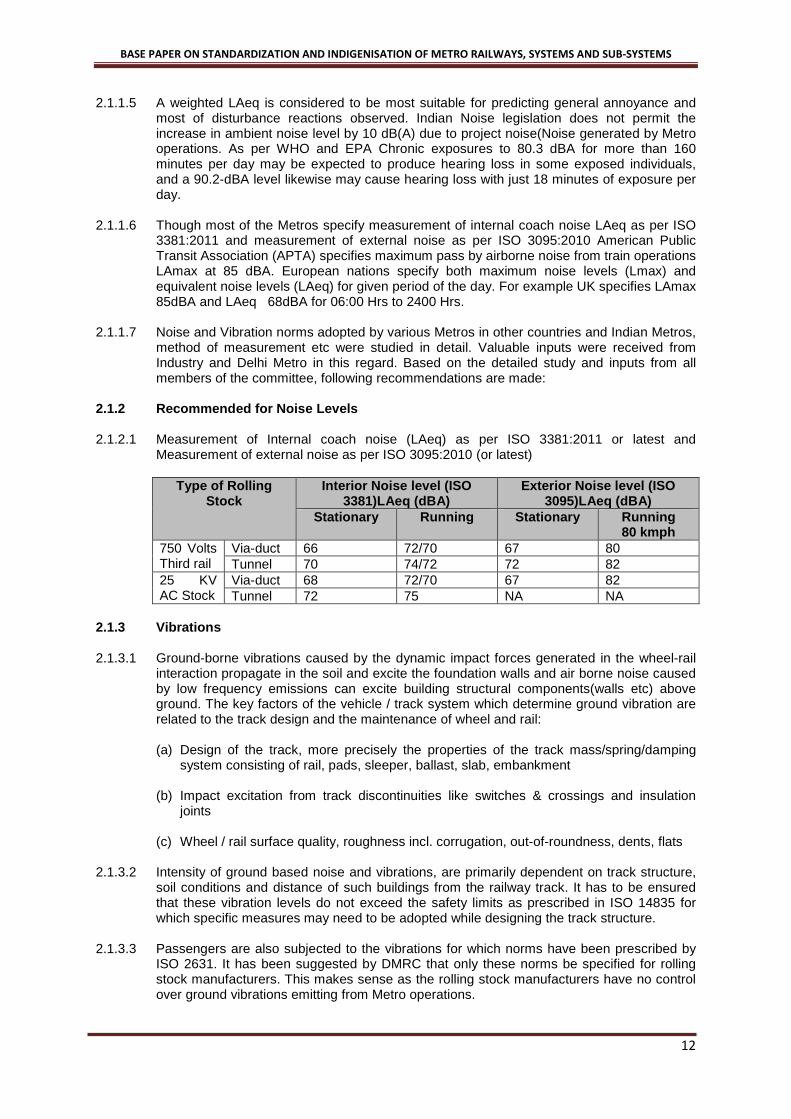
2.1.2.1 Measurement of Internal coach noise (LAeq) as per ISO 3381:2011 or latest and Measurement of external noise as per ISO 3095:2010 (or latest)
Type of Rolling Stock
Interior Noise level (ISO 3381)LAeq (dBA)
Exterior Noise level (ISO 3095)LAeq (dBA)
Stationary Running Stationary Running 80 kmph
750 Volts Third rail
Via-duct 66 72/70 67 80 Tunnel 70 74/72 72 82
25 KV AC Stock
Via-duct 68 72/70 67 82 Tunnel 72 75 NA NA
2.1.3 Vibrations
2.1.3.1 Ground-borne vibrations caused by the dynamic impact forces generated in the wheel-rail
interaction propagate in the soil and excite the foundation walls and air borne noise caused by low frequency emissions can excite building structural components(walls etc) above ground. The key factors of the vehicle / track system which determine ground vibration are related to the track design and the maintenance of wheel and rail: (a) Design of the track, more precisely the properties of the track mass/spring/damping
system consisting of rail, pads, sleeper, ballast, slab, embankment (b) Impact excitation from track discontinuities like switches & crossings and insulation
joints (c) Wheel / rail surface quality, roughness incl. corrugation, out-of-roundness, dents, flats
2.1.3.2 Intensity of ground based noise and vibrations, are primarily dependent on track structure, soil conditions and distance of such buildings from the railway track. It has to be ensured that these vibration levels do not exceed the safety limits as prescribed in ISO 14835 for which specific measures may need to be adopted while designing the track structure.
2.1.3.3 Passengers are also subjected to the vibrations for which norms have been prescribed by ISO 2631. It has been suggested by DMRC that only these norms be specified for rolling stock manufacturers. This makes sense as the rolling stock manufacturers have no control over ground vibrations emitting from Metro operations.
BASE PAPER ON STANDARDIZATION AND INDIGENISATION OF METRO RAILWAYS, SYSTEMS AND SUB-SYSTEMS
13
2.1.3.4 Recommendations: Vibrations to be measured as per ISO 2631, weighted acceleration should be less than 0.315 m/s2
2.2 EMERGENCY EVACUATION SYSTEM
2.2.1 Deliberations / Analysis
2.2.1.1 Committee studied the systems adopted by various Metros worldwide for emergency Evacuation and these include: • Side Evacuation system • Front Evacuation System
2.2.1.2 Side Evacuation In case of side evacuation a walkway is provided along the track. People get out through normal doors and move on the walkway which takes them to the nearest station platform. The relative merits and demerits of this system are as follows: Advantages • In case of DC third rail system evacuation is faster as switching off of power to third rail
is not required. • Evacuation from the train is faster due to large number of doors. Disadvantages • In case of sharp curves, side evacuation is not considered safe as gap between train
and walkway on curve will be very large, which have to be bridged by some plate/footboard
• Side evacuation requires side walkway and hence via-duct width is unnecessarily more and structures are heavy due to extra loading
• Walking on raised walkway is not considered safe for children/elderly passengers
2.2.1.3 Front Evacuation system Top opening door concept: In this concept evacuation door opens upwards on hinges & ramp is deployed to tracks. Merits of this system are: Advantages • No need for extra walkway, hence size of the tunnel as well as via-duct reduces thus is
more economical. • Evacuation is from emergency doors provided at the ends and can be better regulated
by motorman and stampede is prevented. • Walking is easier for passengers in this system as either they have to walk through the
coaches or on the track Disadvantages • Power block is necessary in case of 750 Volts DC third Rail system, which may take
some time • Exit from single emergency door may affect the faster evacuation.
2.2.2 Recommendations
2.2.2.1 Committee recommends that Indian Metros should adopt front evacuation only with door at the centre as is the most prevalent practice world-wide.

BASE PAPER ON STANDARDIZATION AND INDIGENISATION OF METRO RAILWAYS, SYSTEMS AND SUB-SYSTEMS
14
2.3 COUPLING ARRANGEMENT
2.3.1 General There are three different types of couplers used in Metro Rolling Stock: • Fully Automatic Mechanical, Pneumatic and Electrical coupler • Automatic Mechanical and Pneumatic coupling and Jumper cables (IV couplers) for
electrical connection. • Semi-Permanent coupler for mechanical and pneumatic coupling along with electrical
coupling is through jumper cables between cars.
2.3.2 Recommendations
2.3.2.1 For two ends of the train Automatic Mechanical and pneumatic coupling is recommended with Electric coupling through jumper cables. Two rakes need to be coupled in the rescue mode, here time is a consideration, hence automatic mechanical and pneumatic coupling at the two end of the rakes are recommended. Electric coupling shall be using jumpers.
2.3.2.2 Between coaches of the same basic unit Semi permanent couplers are recommended with Electric coupling through jumper cables between cars, as these couplings are used only in sheds during maintenance.
2.3.2.3 Between two basic units In case frequent inter changing of basic units or changes in car formations are required, Automatic Mechanical, Pneumatic and Electrical coupler may be provided. DMRC is providing these Automatic couplers between basic units. As these couplers are most expensive (Approximately 4 times the cost of semi permanent coupler). Hence usage should be only need based.
2.4 PERCENTAGE MOTORIZATION, ACCELERATION/DECELERATION/JERK RATE, POWER TO WEIGHT RATIO
2.4.1 Percentage Motorisation
2.4.1.1 3-Car unit For a basic 3-car train there is no alternative but to have 66% motorization so as to ensure that failure of one motor car does not result in immobilization of train in the section.
2.4.1.2 4-Car unit/8-car trains In case of 4-car/ 8-car trains, only 50% and 75% motorisation is possible. DMRC who have sufficient experience with 50% recommends 75% motorization both for 4-car and 8-car trains. 75% motorisation in 4-car rakes would require three different type of cars. It is thus desirable to go in for 75% motorisation in case of 8-car rakes and 50% for 4-car rakes.
2.4.1.3 6-car/9-car trains In case of 6-car/9-car 66% motorization is a better option on account of following considerations: Advantages • Even with loss of one power car the operational performance is satisfactory, hence
motor coach control can be adopted instead of bogie control.

BASE PAPER ON STANDARDIZATION AND INDIGENISATION OF METRO RAILWAYS, SYSTEMS AND SUB-SYSTEMS
15
• Smaller Traction Motor • Higher level of acceleration and declaration is possible, subject to adhesion limits. • Higher regeneration level is achieved resulting in lower application of friction braking
and consequently less wear of pad /disc. • Energy efficiency is better • Chances of slip/slide even under the worst conditions are reduced due to utilization of
lower adhesion factor compared to the permissible values. Disadvantages • Number of motor coaches will go up which will also result in increase in cost, and
increase in tare weight. There will however be some reduction on account of bogie control in cost of propulsion equipment
• Number of pantographs in 25 kV AC system will go up. This can however be reduced by having one common transformer and single pan to for a 3 car basic unit. This will reduce redundancy as two motor coaches will be out in case of failures of traction transformer
The initial & maintenance cost of propulsion for 66% motorization will be higher, however there will be savings towards energy cost. Worldwide 66% motoring is accepted as the most appropriate.
2.4.1.4 Recommendations: Committee recommends 3-car or 6-car per rake depending on the traffic projections with 66% motorization should be adopted as the standard for all future Metros. In case of 3 car rakes both motored cars should have independent propulsion equipment for complete redundancy.
2.4.2 Recommended Operating characteristics Acceleration, Deceleration, jerk rate etc. are as given below Characteristic 50% Powering 66% Powering Maximum Design speed 95kmph 95 kmph Maximum operating speed 85kmph 85kmph Average acceleration from 0 to 40 kmph in m/s2 for fully loaded train at level track with AW3 load standees 8pax/m2 and seating approx. 50 p/car
0.8 1.0
Service braking rate from 80 kmph to standstill up to fully loaded train on level tangent track
1.0 1.0 m/s2
Emergency braking rate from 80 kmph to standstill up to fully loaded train on level tangent track
1.3 1.3 m/s2
Maximum jerk rate in acceleration or braking in m/s3
0.7 0,75
Minimum Adhesion level 0.20 0.20
2.4.3 Propulsion Equipment–Single source or Consortiums/JVs
2.4.3.1 Issue is whether bids be invited from coach manufacturers as single source with option to source propulsion equipment from sub contractors, or consortiums/JV of coach manufacturers and Propulsion equipment supplier. Rolling stock manufacture involves four distinct requirements, namely: (i) Car body/mechanicals, (ii) train system design & integration, (iii) Propulsion system including TCMS and (iv) Interfacing, testing & commissioning with full MRTS system.

BASE PAPER ON STANDARDIZATION AND INDIGENISATION OF METRO RAILWAYS, SYSTEMS AND SUB-SYSTEMS
16
The above role is normally divided amongst two different set of firms
2.4.3.2 Car manufacturers They specialize in manufacture of car body/mechanicals and integration of propulsion system and TCMS from the specialist suppliers. Examples are BEML, CAF, ROTEM etc.
2.4.3.3 Propulsion Equipment suppliers Propulsion system comprises of Traction Motor, main converter-inverters, auxiliary converters, transformers & TCMS. The propulsion system is quite crucial sub-system of the train. Responsibilities of propulsion system supplier include: • Supply of propulsion equipment including TCMS • Interfacing with other subsystems like HVAC, Lighting, Doors, ATC/ATO, Brake
System, Signalling, Passenger Information system, Power supply etc. • Commissioning and Testing Examples are Toshiba, MELCO, Hitachi, SIEMENS, Bombardier etc.
2.4.3.4 There are suppliers who supply the complete rolling stock including propulsion system. Examples are Bombardier, SIEMENS, ALSTOM, Ansaldo Breda etc.
2.4.3.5 Advantages of Non consortium approachi.e. when propulsion equipment suppliers can be sub contractors which enable competitive pricing as: • Rolling Stock manufacture that manufacture their own propulsion equipment can offer
better competitive price • Rolling stock manufacturers (who do not manufacture propulsion equipment) will have
enough negotiating power with Propulsion equipment suppliers. This will reduce the price.
• As the number of Propulsion equipment manufacturers is limited, consortium approach will restrict the number of bids to number of propulsion equipment manufacturers and thus competition.
2.4.3.6 Recommendations
Committee recommends that car manufacturers can either bid as a single vendor with their own propulsion equipment in case it is manufactured by them and will have an option to source the propulsion equipment from any propulsion equipment supplier as a sub contractor. There should be no compulsion on the car manufacturer to have propulsion equipment supplier as a consortium/JV partner for bidding as consortium. Car manufacturer will have the option to bid as a single vendor or in consortium with propulsion manufacturer,
2.5 ELIGIBILITY CRITERIA
2.5.1 General Description Eligibility criteria should aim at encouraging competition, ensuring reliability and quality and indigenization. Eligibility criteria have a direct bearing on the cost. Broader criteria ensure competitive prices. Rolling stock comprises of Car body and Propulsion equipment. As there are two distinct set of suppliers for Car body manufacturing and propulsion equipment, and Non consortium approach for propulsion equipment supplier is recommended, it is necessary to have separate eligibility/qualification criteria for these two separate set of suppliers.
BASE PAPER ON STANDARDIZATION AND INDIGENISATION OF METRO RAILWAYS, SYSTEMS AND SUB-SYSTEMS
17
Eligibility criteria for car manufacturer must ensure quality, reliability and competitive price of the rolling stock. Taking the views of Industry and Metros into consideration, following eligibility criteria for Rolling stock supplier is recommended.
2.5.2 Eligibility criteria for car manufacturer
2.5.2.1 Bidder consortium or its members, individually or jointly as member of other Consortia have experience and carried out vehicle design, Interface, Assembly & Supply, Testing and Commissioning and should have following credentials: (i) Minimum number of cars:300 metro (i.e. MRT,LRT, Sub-urban railway or high
speed railways) out of which minimum 200 cars shall be of either stain less steel or Aluminium in the last 10 years
(ii) Number of countries: At least one country other than the country of manufacture or in India.
(iii) Operation Performance: 150 cars out of above must be operating satisfactorily against more than one contract in at least one country other than the country of manufacture or in India for last 5 years.
(iv) Projects executed through TOT arrangement with global player, be taken as experience. This will promote indigenization.
(v) Indian subsidiary companies beeligible to bid on the basis of the global credentials of parent company.
2.5.3 Eligibility criteria for Propulsion Equipment Supplier
2.5.3.1 Propulsion equipment supplier can be consortium member or a sub contractor meeting
following requirements: (i) Must have cumulative experience of minimum 10 years in the Design and
manufacturing of propulsion equipment (Traction converter-Inverter, Auxiliary converter/Inverter and Traction Motor rolling stock).
(ii) Propulsion equipment supplied must have been in satisfactory revenue operation for at least five(5) years in minimum 500 cars comprising of both powered and non-powered cars supplied against minimum five different contracts in the Metros of least one country other than the country of manufacture or in India.
(iii) Projects executed through TOT arrangement with global player may be taken as
experience. This will promote indigenization. (iv) Indian subsidiary companies be eligible to bid on the basis of the global credentials
of parent company.
2.6 CONTROL& COMMUNICATION PROTOCOL
2.6.1 General Description Train integrated management system (TIMS) is a complete, integrated system for the control and monitoring of the train-borne equipment. TIMS provides control and monitoring, diagnostic and reporting of the train-borne equipment in a redundant manner. Train Control & Management (TCMS) is a subsystem of TIMS and controls and monitors all train equipment. Subsystems of the train utilize microprocessor-based control. The subsystems are inter-linked via a communication data bus system for the monitoring, fault data logging and for first line diagnostics of faults on board the train. Communication is through the Train Bus (ARCNET) and Local bus (RS-485). IEC 60571 is the International standard for TIMS hardware.

BASE PAPER ON STANDARDIZATION AND INDIGENISATION OF METRO RAILWAYS, SYSTEMS AND SUB-SYSTEMS
18
All the Reputed rolling stock manufacturers have developed their own Train Integrated Management Control System (TIMS) over the years. Even though communication protocols are based on international standards but achieving interoperability with subsystems of alternative vendors is generally quite difficult. Support of the TIMS manufacturer is required for achieving integration.
2.6.2 Recommendations for TIMS Conformity to IEC62280-1 (Safety related communication in closed transmission systems) The hardware systems deployed should conform to international standards. There should be common protocol between TCMS & respective sub-systems. Also Transmission data flow in the network between TCMS & sub-systems can be standardized, so that subsystem supplier of different makes can meet the requirement of monitoring & control of the various parameters through TCMS. Gradually sub-system supplier should adopt IP technology.
2.7 DRIVERLESS TRAIN OPERATION
2.7.1 Main Features • Automatic departure and run from station to station, including automatic turn-back • Door re-opening on train hold command • Remote start of stalled trains
2.7.2 Attendant responsibility • Control passenger doors • Prevent person injuries between cars or between platform and train • Ensure safe starting conditions • Set in/set off operation • Supervise the status of the train
2.7.3 Driverless system on the Indian Metro Projects • Driverless system is the technology, which is well proven now and is strongly
recommended for use in Indian Metro system. • Techno-Commercials considerations are in favour of driver-less system as extra capex
can be recovered in 7-10 years’ time. • Driverless system needs very high reliability and hence detailed designs require extra
time in RAM assurance activities. • Approval and safety certificate from CRS due to lack of technical experience, which can
probably be managed. Driver less operation is required to achieve 85 to 90 seconds frequency for full utilization of Metro infrastructure capacity. This will require communication based Train Control (CBTC) system. Driverless Train Operation can be adopted in phases with signalling up-gradation.
2.8 INDIGENIZATION
2.8.1 General Rolling Stock manufacture includes:

BASE PAPER ON STANDARDIZATION AND INDIGENISATION OF METRO RAILWAYS, SYSTEMS AND SUB-SYSTEMS
19
• Manufacture of Car body& Bogie frames, assembly, integration & testing. Infrastructural facilities for manufacture of car body and bogie frame and its integration are already available in the country. Indigenous sources for certain outfitting items like GFRP panels, grab poles & rails, window glasses, glass wool insulation, electrical panels, battery box, stainless steel and aluminium fabricated items, etc are also available.
• Manufacture of propulsion system including TCMS and other critical sub-systems like
propulsion, brake, door, HVAC, passenger address & Passenger information system, CCTV etc.
2.8.2 Car manufacture
Indigenization of Car body manufacture has already taken place as following manufacturing facilities have already been set up: • BT coach manufacturing unit at Vadodara • BEML Bangalore under TOT from Hyundai Rotem • Alstom setting up unit near Chennai • CAF setting up manufacturing unit in Haryana • Kawasaki is also planning to set up coach production facilities. • ICF and RCF have facilities to manufacture EMU/MEMU coaches which can be up
graded to Metro coaches. Above facilities can take care of the future Metro needs. There is however a need to protect these investments and some incentives need to be given to these units for effectively utilizing the facilities already created.
2.8.3 Propulsion equipment The critical area is indigenization of manufacture of propulsion system, TCMS and other critical sub systems. Global suppliers with satisfactory performance record need to be encouraged to either set up their subsidiary in India or transfer technology to an Indian company through JV. Following steps are necessary to achieve this: (a) Specifications for both rolling stock and traction distribution system are standardized.
This will help indigenization. (b) Standardization will result in higher volumes. It will be possible to leverage the bulk
procurement by a single agency to achieve development of indigenous industry through TOT as has also been done by China.
Presently individual metros are procuring rolling stock in small quantities with different specifications and clause to manufacture 60 to 70% cars indigenously. This does not promote indigenisation of propulsion equipment which is mostly imported. As in case of car body manufacture, indigenous manufacture of complete propulsion equipment in the phased manner also needs to be mandated in the rolling stock tenders. MoUD in order to promote indigenous manufacture of propulsion equipment should give development orders for small quantities to local firms who can either develop on their own or through collaboration with global suppliers. IR has adopted this approach for development of indigenous three phase propulsion equipment for locomotive and EMUs. After successful tests and trials these sources can be considered as regular sources for propulsion equipment. Committee, thus, recommends that a system of bulk order placement may be devised preferably by MoUD by combining requirement of smaller metros. Orders should be placed with at least 70% indigenization clause for both propulsion equipment and car manufacture through TOT with indigenous manufacturers or setting up of Indian subsidiaries.

BASE PAPER ON STANDARDIZATION AND INDIGENISATION OF METRO RAILWAYS, SYSTEMS AND SUB-SYSTEMS
20
3.0 POWER SUPPLY AND TRACTION SYSTEM
3.1 TRACTION SYSTEM
3.1.1 Summary
3.1.1.1 Based on detailed study of various traction systems adopted world over, the study on technical feasibility of traction systems for various levels of traffic and technological development, following position emerges as given in Table-1 below:
Table-1
Type of MRTS
PHPDT Traction Voltage Feasible
Cap Cost*
Energy re-generation
Remark
LRT 15000 to 30000
750 V dc third rail
(a) 125% (a) 18-20% (a) 750 V dc third rail does not have overhead conductor system. It looks good from aesthetic point of view on elevated section. (b) & (c) In U/G OCS does not affect aesthetics
1500 V dc OCS
(b) 115% (b) 20-22%
25 kV ac OCS
(c) 100 (c) >35%
Medium 30000 to 45000
(a) 750 V dc third rail
(a) 135% (a) 18-20%
(b) 1500 V dc OCS (b) 115%
(b) 20-22%
(c) 25 kV ac OCS (c) 100 (c) >35%
Heavy MRTS
> 45000 <75000
(a) 1500 V dc (a) 120% (a) 20-22% (b) 25 kV ac (b) 100 (b) >35%
2X25kV ac May be adopted in busy congested area of city where there are limitations of getting supply at 66kV/22kV and has lesser EMC/EMI problems
*The capital cost pertains to electrification system cost only and it does not capture the impact on rolling stock and civil infrastructure costs due to choice of traction system Note: 1. PHPDT on 750 V dc is validated by subgroup on theoretical study. 2. Issue of aesthetics, however, is a tenuous one in decision-making matrix. While taking
decision based on aesthetics, it should be considered that there is widespread acceptance of OCS even in tourism centric countries like Switzerland and industrialized nations like Japan.
3.1.2 Energy scenario in different traction system
3.1.2.1 Actual records of DMRC (BG Lines - 120 km) & BMRCL (7 Km) reveal an energy saving of
25% in 25 kV ac traction system operating with acceleration of 0.82 m/s2 and maximum speed of 75 kmph verses 750 V dc traction system in BMRCL operating a higher acceleration of 1.0 m/s2 and but lower maximum speed of 65 kmph.
3.1.2.2 Studies indicate that the energy saving in 25 kV ac system may increase to above 35% with the use of higher acceleration of 1.0 m/s2, using 4M+2T rake as compared to existing 750 V dc 4M+2T i.e. both operating with same acceleration and speed.
3.1.2.3 With the increasing cost of electric energy & in an effort to optimize traction energy, now metros working on 750V dc / 1500V dc are exploring methods to improve recuperation of regenerated energy up to 32% even with additional expenditure by using additional technology like inverter, storage devices at sub-stations which are under development and trial in different countries. Cost of these additional technologies, which is substantial at present, however is expected to reduce with the passage of time, deployment of modern electronics & software.

BASE PAPER ON STANDARDIZATION AND INDIGENISATION OF METRO RAILWAYS, SYSTEMS AND SUB-SYSTEMS
21
3.1.3 Impact on Tunnel Diameter
3.1.3.1 It is reported that nowadays, almost similar Machinery & Plant and other facilities are
required for tunnelling of diameter ranging from 5.2 to 5.8 m and therefore only very marginal increase in the cost is expected due to increase in size of the tunnel.
3.1.3.2 Studies indicate that increase in cost due to higher tunnel diameter of 5.6 m in case of 25 kV is substantially offset by reduction in cost due to lesser number of substation and other associated benefits of larger tunnel diameter. Actual differential in cost will depend upon the soil conditions, land availability in the city and the following: • Dimensions (length, width and height) of the coach • Number coaches in train and length of train • Minimum curvature • Type of evacuation (side or front) • Traction Voltage • OCS or Third Rail • Soil Temperature
3.1.3.3 Ideally an optimum size can be arrived at by considering the above factors. However, for practical purposes, for Indian conditions, a tunnel diameter for new Metros may be from 5.2 to 5.7 m
3.1.3.4 Other things being same (coach dimensions, evaluation strategy etc.), theoretically, the adoption of dc third rail traction system (750V or 1500V dc) will require smaller diameter tunnel. However, tunnel diameters adopted in India don’t establish a causal relationship between the traction voltage and tunnel diameters. Experience of many world Metros working with 750 V dc third rail traction system indicate that they have adopted tunnel diameter of around 5.6 m, to derive other benefits of larger tunnel diameter as increase in cost is marginal due to increased earth work and jacketing with the use of modern tunnel boring machines (e.g. 5.4 m for dc & 5.55/5.6 m for 25 kV ac). As per experts, tunnelling cost as a thumb rule can be taken as proportional to tunnel diameter i.e. variation of about 3 to 4% between 5.4 & 5.6 m.
3.1.4 Cost of rolling stock The cost data of rolling stock as per actual contract awarded by various metros in the country are as under: Table 2:Current cost of metro coaches of different Indian Metros
SN Type of traction
Name of Metro
Estimated cost per coach (Rs. In cr) with taxes & including export benefits as on 31st Dec 2012
Estimated cost per coach with spares without taxes and without export benefits as on 31st December 2012
Remarks
1 750V dc
BMRCL**
9.99 9.41 2.88m. wide, 1.0m/s2, 67% motored axle, certain better features compared to KMRCL
KMRCL
9.29 8.05 2.88m. wide, 1.0m/s2, 67% motored axle, flexible PVC clauses for 66% component without any clamping.
2 CMRL 8.74 8.28 2.9m wide, 0.82m/s2, 50%

BASE PAPER ON STANDARDIZATION AND INDIGENISATION OF METRO RAILWAYS, SYSTEMS AND SUB-SYSTEMS
22
SN Type of traction
Name of Metro
Estimated cost per coach (Rs. In cr) with taxes & including export benefits as on 31st Dec 2012
Estimated cost per coach with spares without taxes and without export benefits as on 31st December 2012
Remarks
25kV ac
motored axle, flexible PVC clauses for 66% component without any clamping.
DMRC** RS2 9.26 8.73 3.2m wide, 0.82m/s2, 50%
motored axle RS3 10.09 9.97 2.9m wide, 0.82m/s2, 50%
motored axle Phase III (RS10)
8.58 (1st Apr 2013
7.91 3.2m wide, 1.0m/s2, 67% motored axle, more energy efficient
Hyderabad** 10.23* 8.77 2.9m. wide, 1.0m/s2, 67% motored axle,
*Unlike other Metros, this figure is firm price with no variation due to exchange rate throughout the contract period and also without any deemed benefit. **PVC clauses in respect of DMRC, BMRCL and HMRL have lower flexiblecomponent with a fixed clamping of 3%, unlike, KMRCL and CMRL.
3.1.4.1 The propulsion equipment of the ac rolling stock comprises of two additional majorequipment, viz. transformer and front end converter. Examination of quotesreceived by DMRC in 2000, for AC and DC rolling stock of same performancerequirement in the RS-1 tender for underground line shows that the cost of 25 kVac rolling stock is more than 1500 V dc rolling stock by Rs 37 lakhs, i.e. by 9%.Total additional cost of rolling stock of 25 kVac for 68 coaches for this line worked out to Rs.25 crores and reduction in traction & power supply arrangement from1500 V dc to 25 kV ac for the same line was Rs.64 crores. However,advancements in technology like use of higher dc link voltage and singletransformer for multiple motor coaches are now resulting in reduction in cost of acrolling stock. The difference in 25 kV ac vis-à-vis 750 V dc rolling stock would belower than 9%.
3.1.4.2 The procurement experience of different Indian Metros shows that the cost of 25kV ac rolling stock is comparable with 750V dc rolling stock. Though the above figures indicate the cost of 25 kV ac rolling stock is comparable with the 750 V dc rolling stock but this gets influenced by many factors such as:
(a) Number of coaches (b) The specifications viz. acceleration, deceleration, scheduled speed, special features
required which are entirely not the same in above cases. (c) DC link voltage (d) Commercial Conditions: defect liability period, indigenization clauses, price variation,
delivery period, time frame for completion, ambient conditions, etc. (e) Risk factors perceived by the bidders
3.1.4.3 The propulsion equipment forms nearly 20-25 % of the cost of rolling stock and this gets influenced in 3-phase drive systems by the additional equipment required in 25 kV ac (traction transformer and converter) and in dc the size of the traction equipment because of lower permissible dc link voltage as compared to higher permissible dc link voltage in ac stock.

BASE PAPER ON STANDARDIZATION AND INDIGENISATION OF METRO RAILWAYS, SYSTEMS AND SUB-SYSTEMS
23
3.1.5 World Scenario and Other Recent Developments
3.1.5.1 Out of 184 transit systems worldwide having 573 lines and 9394 stations with a combined
length of 10641 km, more than 50% have 750V dc third rail system. Over 12 heavy metros have overhead 1500 V dc system. Recently heavy metros like Seoul, Delhi, Hyderabad and Chennai have adopted 25kV ac system. Bangalore Metro with projected traffic level up to 45,000 PHPDT has adopted 750V dc system.
3.1.5.2 1500V dc third rail has recently been adopted by Guangzhou and Shenzhen Metros in China on a few lines. It is learnt that this has been developed by Chinese Industry recently in association with European industry. The Committee visited Guangzhou Metro to study experience and design aspect of 1500V dc third rail system.
3.1.5.3 Regeneration of energy has been feasible in modern rolling stock because of development of VVVF drive in 1990s & old metro Rolling Stock does not have this feature.
3.1.5.4 Studies indicate that 1500 V dc or 25kV ac is essentially required for PHPDT above 45000. Based on the cost incurred by Indian Metros in recent past it is noted that 25 kV ac is economical, from direct cost of electrification point of view, compared to 750V dc even above a PHPDT of 30,000 both from initial cost point of view as well as energy efficiency.
3.1.5.5 From aesthetic point of view, 750 V/1500 V dc third rail gives better aesthetics as it does not have overhead conductor system (OCS).
3.1.5.6 2x25kV ac system, which is energy efficient and have lesser EMC/EMI problems, can offer viable solution for congested city. This traction system has been adopted by Seoul Metro on their Sin Bundang line. It requires further detailed study for adopting in Indian Metros.
3.1.6 Indigenisation Level of Hardware and Software of Traction System
3.1.6.1 For modern 750V dc traction system some of the major systems like low loss composite aluminium third rail, oil-less (dry type) transformer rectifier set, dc switchgear, high speed circuit breaker, bus duct etc. are not available indigenously.
3.1.6.2 Modern 25kV ac system, adopted by Delhi Metro, has a few fittings different than and superior to Indian Railways. Some of the sub-systems like light weight section insulators, typical potential transformer and current transformer, neutral section arrangement, 25 kV gas insulated switchgear in traction sub stations and switching stations, rigid overhead system, synthetic insulators etc. are imported.
3.1.6.3 Items for indigenisation of 750 V dc and 25 kV ac on immediate basis have been given in annexure XII (of the Report).
3.1.6.4 Simulation programmes are essential to determine and predict requirement of traction load, for various headways of trains, study of EMC/ EMI effect, sizing of equipment etc. Presently, these are propriety of few firms in the world and metros are getting it done from them. But neither metros have any knowledge about these simulation programme nor it is available with them. There is need for development of simulation package in India with the help of institutes like DTU, IITs and industry.
3.1.7 The Way Forward
3.1.7.1 In view of the above, presently Metros in India may consider adoption of 25 kV ac or 750 V dc. The objective and considerations for selection of 750 V dc or 25 kV ac should keep in view route of a particular rapid transit line in the city, elevated or underground, above knowledge of technical feasible systems, their capabilities, economic viability based on capital cost and operational cost, platform screen doors, aesthetics and environmental conditions peculiar to the area of the city.

BASE PAPER ON STANDARDIZATION AND INDIGENISATION OF METRO RAILWAYS, SYSTEMS AND SUB-SYSTEMS
24
3.1.7.2 1500V dc third rail may also be considered by some metro on experimental basis for few lines involving higher PHPDT on aesthetic consideration, which can be examined later on for further consideration.
3.1.8 Auxiliary & Traction Power Supply
3.1.8.1 Study reveals that it is essential to have ring main or duplicate system at high voltage from reliability and continuous availability of power supply point of view. Most of the metros world over have adopted ring main system at high voltage of 33 kV/22 kV or 11 kV depending upon local power supply network in use. This starts from receiving sub-station. At each station, auxiliary sub-station steps down to 400/ 230 V from 33 kV or 22 kV or 11 kV for further distribution. All the metros in India have adopted either ring main or duplicate system. Mostly, 33kV ring main has been adopted in India by Delhi, Chennai, Hyderabad and Bangalore. Metro lines in Mumbai have adopted 22kV and in Kolkata 11kV as prevalent there.
3.1.8.2 To meet emergent situation in case of failure of 33kV, the stations are provided with DG sets for essential services to meet essential loads like signaling, fire protection, lighting etc.
3.1.8.3 In U/G stations major equipment design has to give due attention to eliminate fire hazards. Special panels, fire retardant cables, fire retardant dry type transformers have been used. Some of these equipment like fire detection cable, fire alarm panel etc. are still not available indigenously. A few equipment have been developed and are being manufactured in India.
3.1.8.4 In case of 750/1500 V dc system some of the Metros have adopted common ring main 33 kV cable system for traction and auxiliary supplies depending upon the reliability of grid supply voltage (Dubai, Guangzhou, Kolkata) instead of separate ring main system for traction and auxiliary supply (Bangalore). Techno-economic study may be taken up while planning for a new Metro system, peculiar to the city.
3.1.9 Indigenization – Status, Constraints and way forward
3.1.9.1 Current Status (a) 750V dc system: Modern technology 750V traction system of Bangalore Metro uses
composite aluminium third rail, dry type of transformer rectifier, dc switch gear and high speed breaker (HSCB), bus duct. These are all presently imported and have a small volume of requirement. Other components like cable, RSS equipment are indigenously available. Indigenization of these imported components need to be explored through industry dealing with Railway traction equipment.
(b) 25kV ac system: Delhi Metro while adopting 25kV ac system have imported few
components / equipment like light weight section insulator, potential transformer, neutral section, rigid OCS and GIS from reliability and maintainability point of view. Delhi Metro has placed developmental order for section insulator and indigenization of other items needs to be explored.
Copper Conductor, mast and other switch gear are now available indigenously. Synthetic insulator has been developed indigenously & used extensively on Delhi Metro.
3.1.9.2 Constraints in Indigenization
(a) Local industries do not have know-how for the design, control, manufacture and quality
assurance of imported items. (b) Volumes may not be attractive for local industries, interaction with global players to set
up a manufacturing base in India in some cases needs to be pursued.

BASE PAPER ON STANDARDIZATION AND INDIGENISATION OF METRO RAILWAYS, SYSTEMS AND SUB-SYSTEMS
25
(c) There would be an issue of IPR with the OEM which requires to be discussed and
examined further.
3.1.9.3 Strategy of Indigenization (a) Common enabling specifications of systems/sub-systems for all metros can increase
volume of requirement and encourage Indian industries having facilities for manufacturing similar items for Indian Railways for indigenization of these items.
(b) Some items can be entrusted for indigenization through industries by overseas firms/
units. (c) However, to ensure technology up-gradation, investments by Indian industries, it is
necessary to have a policy framework for encouraging indigenization and to detail out mechanism for assured market.
3.1.9.4 Development of Software and Hardware
(a) There is need for tie up with Engineering Colleges/ DTU/ IITs for development of
software, simulation packages/innovation. Development of sub-systems, and hardware for availability and maintenance needs and substitution for obsolescence etc.
(b) RDSO while doing akin work for Indian Railways may also be encouraged to take up
similar work in association with experts/Indian Institutions.
3.1.10 Energy Efficiency
3.1.10.1 Regeneration absorption capability (a) While on 25kV ac, re-generation above 30% is possible to be achieved due to higher
voltage, longer feeding zone but on 750V dc system, it remains around 18 to 20% only because of voltage drop. Measures are under development in other countries to further retrieve re-generated energy in 750V dc system. In this regard following energy storage equipment at substation are reported to be under use/trial in other countries:
• Fly wheel • Super capacitor • High capacity battery • Inverter
(b) These need to be studied further & discussed with developers.
3.1.10.2 Energy Efficiency Measures in Metros (a) A study conducted on energy efficiency has identified following factors in design of
Metro systems as given in Table 3 below. Status in respect of these factors in DMRC, BMRCL and CMRL is given in juxtaposition in Table 3.
Table 3: Improving Energy Efficiency SN Factor Contribution towards Energy Efficiency
DMRC BMRCL CMRL 1 Gradient Adverse Adverse Adverse 2 Station Spacing Neutral Neutral Neutral 3 Air-conditioning (Normally
takes upto 20% of the energy)
Adverse - -
3 Regenerative Braking (Max 50%)
Favourable Favourable Favourable
4 Driving skills (ATO, ATP) Favourable Favourable -
BASE PAPER ON STANDARDIZATION AND INDIGENISATION OF METRO RAILWAYS, SYSTEMS AND SUB-SYSTEMS
26
SN Factor Contribution towards Energy Efficiency DMRC BMRCL CMRL
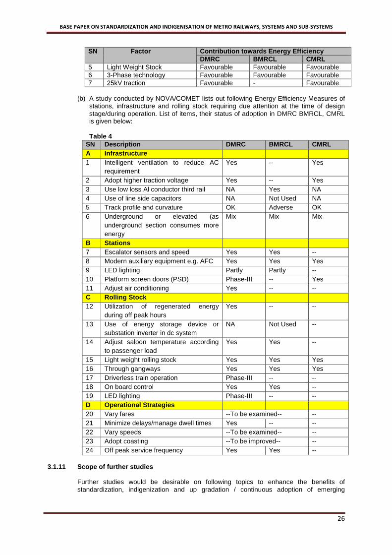
5 Light Weight Stock Favourable Favourable Favourable 6 3-Phase technology Favourable Favourable Favourable 7 25kV traction Favourable - Favourable
(b) A study conducted by NOVA/COMET lists out following Energy Efficiency Measures of
stations, infrastructure and rolling stock requiring due attention at the time of design stage/during operation. List of items, their status of adoption in DMRC BMRCL, CMRL is given below:
Table 4
SN Description DMRC BMRCL CMRL A Infrastructure 1 Intelligent ventilation to reduce AC
requirement Yes -- Yes
2 Adopt higher traction voltage Yes -- Yes 3 Use low loss Al conductor third rail NA Yes NA 4 Use of line side capacitors NA Not Used NA 5 Track profile and curvature OK Adverse OK 6 Underground or elevated (as
underground section consumes more energy
Mix Mix Mix
B Stations 7 Escalator sensors and speed Yes Yes -- 8 Modern auxiliary equipment e.g. AFC Yes Yes Yes 9 LED lighting Partly Partly -- 10 Platform screen doors (PSD) Phase-III -- Yes 11 Adjust air conditioning Yes -- -- C Rolling Stock 12 Utilization of regenerated energy
during off peak hours Yes -- --
13 Use of energy storage device or substation inverter in dc system
NA Not Used --
14 Adjust saloon temperature according to passenger load
Yes Yes --
15 Light weight rolling stock Yes Yes Yes 16 Through gangways Yes Yes Yes 17 Driverless train operation Phase-III -- -- 18 On board control Yes Yes -- 19 LED lighting Phase-III -- -- D Operational Strategies 20 Vary fares --To be examined-- -- 21 Minimize delays/manage dwell times Yes -- -- 22 Vary speeds --To be examined-- -- 23 Adopt coasting --To be improved-- -- 24 Off peak service frequency Yes Yes --
3.1.11 Scope of further studies
Further studies would be desirable on following topics to enhance the benefits of standardization, indigenization and up gradation / continuous adoption of emerging

BASE PAPER ON STANDARDIZATION AND INDIGENISATION OF METRO RAILWAYS, SYSTEMS AND SUB-SYSTEMS
27
technologies with a view to remain modern and avail benefits of evolving technologies.Some of the areas identified for immediate studies are: (i) 2x25kV ac traction system for metro (ii) Adoption of new technology at substation level to improve level of regeneration in dc
traction system (iii) On merits and demerits for adopting two ring main circuits, one for traction and other for
auxiliary with provision to meet emergency requirement by either circuit vis-à-vis three ring main circuits and four ring main circuits in dc traction system.
(iv) Merits and demerits of taking auxiliary power supply (33/11 kV) at each metro sub-station directly from Electricity Supply Company rather than running 33 kV cables for transfer of power on via-ducts.
(v) Strategy for cost reduction of 750V/1500V dc traction system by adopting design criteria of outage of one transformer rectifier set instead of one TSS.
(vi) Energy efficiency measures similar to European rail road research map for adopting in Indian Metros.
(vii) Simulation studies to evaluate energy saving in 25 kV ac vis-a-vis 750 V dc traction system with similar performance and under similar operating & climatic conditions with advance technology 4M+2T rake composition.
(viii) Based on experience of Ahmadabad Metro of 1500 V dc third rail system and further studies, development of Engineering & Designs for this system and its interface with Rolling Stock/Current Collecting Device (CCD) can be taken up.

BASE PAPER ON STANDARDIZATION AND INDIGENISATION OF METRO RAILWAYS, SYSTEMS AND SUB-SYSTEMS
28
4.0 SIGNALLING SYSTEM
4.1 INTRODUCTION Following the decision of the Ministry of Urban Development (MoUD) to study the ways and means for standardization of Metro Rail systems primarily for standardization and reduce costs, a sub-committee for signalling and train control was appointed and this report details the deliberations and outcome as also the conclusions and recommendations. Metro Signalling & Train control system technology focus means of reducing headway, ensuring safety and improving efficiency and reduction in cost of operation. The Signalling & Train Control system on Main Line Railways and Metros are different on account of very different traffic requirement besides civil and E&M infrastructure. Signalling & Train Control in metros not only ensures train safety, but it also integrate, interface and automates areas of operation, driving, passenger information, collection of information and analysis of the same. Signalling & Train Control systems have been dominated by use of Track Circuit based Signalling & Train Control for more then five decades. The use of transmission based (cable loop) system started in late 1980, but did not find many takers, further due to technology and environmental challenges. However, with the technology advances in telecommunication and IT, the CBTC have now become preferred technology for metros world over. The Sub-Committee has explored level of this technology and recommended this be perfect platform of all future metros and Mono Rail Signalling & Train Control systems.
4.2 SUMMARY OF CONCLUSIONS Taking into account i) the increasing obsolescence of AFTC based Train Control System, ii) non-feasibility of using ETCS for Metro / Mono rail on account of headway requirements and due to absence of ATO and ATS and iii) considering the benefits of i.e. less field equipment, lesser impact of perturbation, better headway beside competitive investment costs, CBTC based Train Control systems, the committee felt that the efforts for standardization should proceed with CBTC platform for Train Control Systems and where ever possible CBTC systems should be planned for use in Metro / Mono Rail systems in future in India. These guide lines may be reviewed periodically with change in technology.
4.2.1 Interoperability and R&D Considering the current mature status of Train Control Systems, and R&D structure in India, starting from scratch for developing a system on its own is not considered a feasible activity for any project. This is especially so, as even the international experience of attempts for interoperability have not been satisfactory. It was unanimously agreed by the sub-committee that de-novo R&D for this purpose should be done as parallel activity even as standardization is given priority. Any proposal for adopting specifications of MTA new York or RATP, Paris for inter operability or inter changeability for CBTC for the short term is also considered inadvisable in view of the current status of the Projects in these Metro Networks and taking into account the limitations of only two-three firms available with the experience of these specifications and thus creating an isolated island. While indigenization may not be feasible for the core area for some time to come, efforts should be made to standardize the sub-systems to the maximum extent possible on a continuing basis with periodic review of the standards to keep up with technological advances. The ongoing efforts of MTA / New York and RATP / Paris could be kept under observation by a suitable technical committee on a continuous basis to decide in the long term whether adoption of these specifications with any customization or modifications is feasible from techno economic consideration.
4.2.2 Sourcing Locally For the long term projects including re-signalling contracts, feasibility of setting up of two or more joint ventures of Indian private sector firms with established CBTC vendors should be
BASE PAPER ON STANDARDIZATION AND INDIGENISATION OF METRO RAILWAYS, SYSTEMS AND SUB-SYSTEMS
29
explored, with all the hardware locally produced and only the core software supplied by the established player. This will require more detailed and in-depth study and interaction with all stake holders. As another long terms option, feasibility should be examined for setting up of a nodal R&D establishment to support all the efforts for standardization, assist the joint venture firms, identify and encourage gradual local sourcing of sub-systems and finally produce fully owned solutions for implementation in the longer term. Involvement of Academic Institutions, software firms and firms manufacturing control systems, other R&D organization in DRDO or ISRO may help in this venture to provide a solid local base for future Train Control systems for India. This R&D effort may also be financed by Government of India through annual grants. Representatives of the industry also acknowledged that efforts to standardize help the industry in their long term planning and provide clarity in the market. However, suppliers felt that the requirements of such systems should be sufficient large for the industry to get involved and make the process a success. Point machine for depot, including clamp lock, cables, LED signals, UPS and associated system, site accessories, computers and server, Direct Line Projectors,entire wiring activity can be done in India. For software confirmation, data for Interlocking, ATS, Signal Plan and associated design beside testing and commissioning activity to be done by local resources. It would be essential to increase the local sourcing in the Train Control systems in order to ensure availability of local expertise on a continuing basis for the life term of the equipment to have a control over total cost of operation and not the project costs alone.
4.2.3 Synergy with IR to increase local sourcing
4.2.3.1 Indian railways have taken a policy decision to adopt large portion of network, it was felt that common subsystems between main line and metro systems may be increased substantially; concern of low volume for TPWS / TCAS for improving the sourcing from within the country will remain. It was concluded that the requirements for Metro Rail systems in the Indian market alone for these components may not be sufficient to drive the local sourcing efforts in core sub-systems. If IR goes for ETCS in a big way, components of ATP such as Odometers, Balizes / beacons, Antenna systems, AFTC etc could be eventually available within the country. It was also concluded that the requirements for Metro Rail systems in the Indian market alone for these components may not be sufficient to drive the standardization or local sourcing efforts. It was also concluded that equipment such as Point machines in depot and LED signals which are also common to Indian railway requirements may be stipulated for use in the Metro rail systems.
4.2.3.2 Data Preparation activity in India It has been possible by DMRC efforts that the industry has started data preparation activity in India and there are two active examples (i) of Alstom who have set up a data centre in Bangalore and (ii) Infotech at Hyderabad. It is understood that M/s Siemens and Bombardier are also planning the same activities in India.
4.2.4 Automatic Train Supervision system Suggestions were also made that the portions of ATS subsystem could be delinked from the Train control system and could be standardized separately such that even non-signalling firms in the Information technology sector can develop and provide the same locally as long as the protocols and the interface between signalling and ATS could be standardized. Hence delinking of ATS in the case of Metro systems should be considered, perhaps for the long term, for which a detailed study to define modules / sub-modules is recommended.

BASE PAPER ON STANDARDIZATION AND INDIGENISATION OF METRO RAILWAYS, SYSTEMS AND SUB-SYSTEMS
30
4.2.5 Software and configuration centre Some members felt that mandating the setting up of design office within India with 80% of Indian staff with software skills with only 20% domain experts as one team, will help in reducing the costs for owner as well as the vendor as it is a form of software outsourcing to India which is already in vogue for application design with some of the signalling suppliers. It may be desirable to stipulate that indigenous manufactured / supplied items should be used to the maximum extent possible within the stipulated guidelines of funding agency such as JICA, procurement process. If local suppliers of equivalent standards of quality are not available for a particular item, then only importing may be permitted. Contractual conditions could be included to this effect in the tender. In the long run such a condition will ensure gradual increase in local content as more and more firms within the country are able to produce similar products with the required quality. Applying the “offset” policy of Ministry of Defence was considered to be out of the preview of Sub-Committee.
4.2.6 Proposed course of action
4.2.6.1 It is suggested that these systems may be implemented with CBTC based ATC systems. The standards will be generally as per IEEE 1474; the radio frequency and features to be employed may be decided by the respective Metro Administrations. Efforts to get frequency allocation for CBTC to continue. Local sourcing and framing of suitable tender conditions to this extent could be explored: (a) Any component such as axle counters, switches, Point Machines, Track work, Racks,
Cables etc. (b) Interlocking design including lighting protection, cabling, racks, bungalows (c) Data preparation, customization, verification, validation beside detailed design for
electronic interlocking may be done in India. (d) Installation, equipment staging, testing, commissioning (e) point machine for depot, LED signals (main and shunt), cables should be attempted for
these systems to the maximum extent feasible and to this extent framing of suitable tender conditions could be explored.
4.2.6.2 It will be in the interest of Metro development in the country and also for development of
industrial base, Sub-Committee is of the opinion that from a strategic view point, following action may be taken: (a) Set up a Research & Development centre, with experts of domain knowledge. For
advice and guidance the R&D centre may have affiliations with software firms, Academic institutions, Govt. R&D labs under ISRO/DRDO etc. The R&D centre should be funded by GoI with a governing board with members from Ministry of Urban Development.
(b) To develop a local base for these systems in India, Government may invite proposals
and tie-up with well known suppliers in the field through a transparent process. This should be preferably in the form of Joint Venture and include participation of the private sector an example of RATP/Alstom and GE/MRTC is precursor.
(c) Development of ATS software and use of commercially available industrial hardware, a
dedicated team need to be setup in the field as early as possible, since this is a activity, which yield dividends not only for Metros, but also for the Main line of the Indian Railway.
BASE PAPER ON STANDARDIZATION AND INDIGENISATION OF METRO RAILWAYS, SYSTEMS AND SUB-SYSTEMS
31
4.3 RECOMMENDATIONS
4.3.1 General
Indigenization of ATCS systems as such may not be feasible in short run as efforts to produce an indigenous system from scratch by de-novo R&D need long term resources and commitment. Initially efforts should only focus on standardization.
4.3.2 Local Sourcing Equipment such as Point machines for Depot, LED signals, Signalling cables for at grade and elevated sections, quad cables and OFC cables etc which are also common to Indian Railway requirements and for which sufficient manufacturers are already available can be used in the Metro rail systems instead of importing them. Data preparation, configuration for interlocking, ATS and interlocking design sourcing may be done locally. Feasibility of using local hardware for displays, servers etc should be examined and even in the case of hardware closely linked with the safety system, possibility of weight-age or incentives should be examined to encourage the established vendors to set up local factory for manufacture of the same as has happened in the case of rolling stock.
4.3.3 Develop ATS Feasibility of delinking the portions of ATS from the safety systems of ATC to be planned and implementation process started so that this portion can be sourced locally as enough Information technology vendors exist in India.
4.3.4 CBTC for Metro and Mono Rail CBTC as a technology has become stable and mature and in view of the many fold advantages over the earlier AFTC based Train Control Systems, CBTC based Automatic Train Control Systems may be generally Train Control platform in all Metro rail and Monorail networks of India except extension of existing lines or requirement necessitate otherwise. Radio based CBTC system may be proposed for the above purpose and unless better technology advances take place, CBTC may be implemented. DOT to be requested to reserve a frequency Band without payment of spectrum.
4.3.5 Interoperability Inter-operability may be kept only as a long term goal in view of the massive efforts and funds required to achieve the same as seen from the progress made and experience of the international projects. If any useful immediately implementable inputs become available from the international inter-operability projects, these can be gainfully adopted for the benefit of the country as and when feasible. For development of Indian industry and also as a strategy for development of manufacturing and software capability in India, it is necessary that long term efforts should start for creating manufacturing and software base in India. Though it may not be possible to achieve inter-operability as has been seen from experience of New York Metro and RATP, for the time being, India could participate in appropriate international forums to promote CBTC inter-operability as a global need and objective. For the long term, efforts should be made to encourage setting up of two or more joint ventures of private sector firms with an established CBTC vendor with the objective of manufacture and supply of the whole system locally.
4.3.6 Design Centre

BASE PAPER ON STANDARDIZATION AND INDIGENISATION OF METRO RAILWAYS, SYSTEMS AND SUB-SYSTEMS
32
It may be desirable to encourage vendors to set up design office within India with software skills and domain knowledge especially in the area of data preparation for Interlocking, ATS and Interfaces. GoI should set up an R&D centre for the purpose of centralizing, standardization efforts, to identify and encourage local sourcing of all hardware and sub-systems and gradually develop an indigenous version of CBTC which could be licensed for manufacture to the identified joint venture firms.

BASE PAPER ON STANDARDIZATION AND INDIGENISATION OF METRO RAILWAYS, SYSTEMS AND SUB-SYSTEMS
33
5.0 OPERATION AND MAINTENANCE
5.1 KEY FINDINGS
5.1.1 Delhi Metro and Bangalore Metro
5.1.1.1 Delhi Metro and Bangalore Metro follow almost similar O&M practices where in Train operations, OCC, DCC, Station Control, Customer Relations and maintenance of major assets (Rolling Stock, Track, Signalling& Telecom, Traction Power and AFC) are managed In-House with specially recruited and trained staff for this purpose.
5.1.1.2 House-keeping, Manning of Ticket Counters are out-sourced. Similarly maintenance of few assets such as Elevators, Escalators, Fire-fighting, AC system, DG &UPS are partly out-sourced. Station building maintenance is fully out-sourced.
5.1.1.3 On Delhi Metro, Security is managed by Central Industrial Security Force (CISF) and Delhi Police. On Bangalore Metro, Auxiliary Security is outsourced, supervised by Chief Security Officer /BMRCL. Karnataka Industrial Security Force (KISF) is being raised. Bangalore Police is responsible for crime investigation.
5.1.1.4 DMRC and BMRCL are monitoring Key performance parameters – Ridership, Fare box & non-fare box Revenue, Customer satisfaction, Energy Consumption (Traction & Non Traction), Punctuality, Train Withdrawal from service, Incident/ System Defects not affecting train operations, Evacuation, Accidents, etc. Key Performance Indices (KPI) as per international practice are yet to be implemented. DMRC has become a member of NOVA, which will enable them access to international O&M practices and adoption of KPI in line with international Metrorail systems. BMRCL has applied to NOVA for membership.
5.1.1.5 Maintenance regime comprises of “preventive” and “corrective” maintenance. Maintenance periodicity & schedule as prescribed by OEMs are followed to start with. Based on experience gained, O&M schedule and periodicity are reviewed / revised.
5.1.1.6 The O&M cost per RKM for the year 2011-12 on DMRC is Rs. 3.76 Cr. The annual O&M cost for BMRCL is about Rs. 3.55 Cr. The O&M cost is considered optimal.
5.1.2 Hyderabad Metrorail project
5.1.2.1 Hyderabad Metrorail project is being implemented on PPP basis. M/s L&TMetro Rail (Hyderabad) Ltd (a special purpose vehicle) is the concessionaire on DBFOT basis for 35 years extendable by another 25 years.
5.1.2.2 LTMRHL has engaged Keolis SA France as its O&M contractor (OMC) through International Competitive bidding for a contract period of 5 years from first Commencement Date (COD).
5.1.2.3 The scope of services of OMC is covered in 3 phases viz. Consultancy Phase, Pre Operation Phase and Operation Phase. OMC is associated right from the design stage of the project (early involvement of operator) to provide O&M inputs while finalizing the designs.
5.1.2.4 KPIs to international standards are prescribed and committed in the O&M contract.
5.1.2.5 OMC will out-source certain activities e.g. House-keeping, Auxiliary security, Rail Grinding, Elevator / Escalators maintenance etc.
5.1.2.6 LTMRHL are likely to commence revenue operations of first section in March2015 with commissioning of entire project by June 2017.
5.1.3 Rapid Metrorail Gurgaon Ltd (RMGL)

BASE PAPER ON STANDARDIZATION AND INDIGENISATION OF METRO RAILWAYS, SYSTEMS AND SUB-SYSTEMS
34
5.1.3.1 RMGL is implementing a small network of 5km in the city of Gurgaon and likely to commence revenue operations in the year 2013-14.
5.1.3.2 RMGL has decided to award the maintenance contract for Rolling Stock, Signalling, and Traction Power to the OEM (M/s Siemens) .They also plan to out-sourceHouse-Keeping, Ticket selling, maintenance of Elevator / Escalators etc.
5.1.3.3 RMGL has planned to under -take core operations such as train operations, manning of SCR, OCC, DCC and maintenance of track with the in-house staff.
5.1.3.4 The section being small, the cost of O&M is not representative.
5.1.4 One of Indian Metrorail System One under-construction metro railway invited global bids for selection of O&M contractor. For reasons of high tender bid cost (Rs 8 Cr. per annum per RKM.) and multiple legal interpretations of bid parameters, the tender has been discharged. The metro railway has decided to follow the O&M model of DMRC and BMRCL.
5.1.5 Singapore Metro (SMRT)
5.1.5.1 SMRT (Govt Company) operates many metro lines in Singapore under an agreement with Owner of the Metro Project viz. M/s Land Transport Authority (LTA).The complete operation and maintenance and capacity augmentation (like additional trains, ticketing gates etc.) is the responsibility of the SMRT.
5.1.5.2 SMRT is responsible for a strict KPI given in the Agreement and failure to achieve the KPI leads to penalty regime.
5.1.5.3 All major activities of O&M are carried out in-house by SMRT except minor activities (like cleaning, ticket selling, Lifts & Escalator maintenance etc.) are outsourced.
5.1.5.4 SMRT has a comprehensive AMS system to capture all maintenance data history and also plan the maintenance.
5.1.6 Bangkok Metro (MRT)
5.1.6.1 MRT Bangkok has out-sourced the maintenance for Purple lineto M/s Siemens who has to follow a strict KPI as given in the agreement.
5.1.6.2 MRT carries out the core operations in-house.
5.1.6.3 MRT has become a member of American Public Transportation Association (APTA) and NOVA, with the objectives to study and exchange the excellent practices with other international public transport operators.
5.1.7 Dubai Metro Dubai Metro has outsourced the entire O&M services to M/s SERCO, UK. The cost of Operation and Maintenance of Foreign Metrosare not available because of confidentiality agreement.
5.2 RECOMMENDATIONS FOR O&M
5.2.1 Training Institute/Centre To overcome shortage of O&M personnel, each Metro Rail administration should adopt the policy of recruiting fresh qualified staff, train anddeploy them for O&M services after due competency certification process. Training institutesare essential for initial training

BASE PAPER ON STANDARDIZATION AND INDIGENISATION OF METRO RAILWAYS, SYSTEMS AND SUB-SYSTEMS
35
andcontinuous skill development of the employees. Therefore each Metro Rail should have either training instituteof their own or enter into aMoU with other Metrofor training of the staff. Thetraining institute should be accredited to an authorized body.
5.2.2 Metro Railway Research Centre State of the art technologies are being employed on Metro Rail projects. The absorption of these technologies by the Indian industry is essential for the country to be self-sufficient in future. A Metro Railway research institute / centre should be setup by the Govt of India in collaboration with reputed Educational Institute (IIT/IISc etc.) to undertake research in Metro Rail Technologies. This research centre should become a Nodal agency for guidance of Metro Railways in Technology selection/upgardation etc..
5.2.3 Association of Metro Rail Operators in India For periodic exchange of ideas, sharing of good practices, new technologies adopted, streamlining KPI, benchmarking operation & maintenance practices, an association of Indian MetroRail Operators should be set up. This will enable:
• standardization of O&M practices in the long run. • Absorption of the technologies • Indigenization
5.2.4 Asset Management System
Each Metro Railway should procure a comprehensive asset management system (AMS) to capture all maintenance data history and also plan the maintenance covering all assets viz. Rolling stock, Traction Power, Track, Signalling& Telecom, AFC, Civil Structure and Depot equipment’s etc. The AMS shall have suitable integration with the ERP system. Standardization of mandatory spares, consumable spares, DLP spares etc., in various procurement contracts & inventory control system needs to be evolved.
5.2.5 Spare parts sourcing Spare parts to be procured from OEMs under long term supply agreement.
5.2.6 Security of Metro Rail System Security of the passengers, metro staff and assets is of paramount importance. A comprehensive security plan as per guidelines issued by Ministry of Home Affairs/GoIbe chalked out on each Metro Railway in consultation with the respective state Government. The detailed project report should have a separate chapter on Metro security covering all aspects of security.
5.2.7 Safety Assurance Case
5.2.7.1 Safety certification of the Metro system presently requires Oscillation Trials & Speed Certificate by RDSO. For signalling safety normally Independent Safety Assessor (ISA) are appointed. Upon receipt of above reports and documents submitted by the Metro Rail administration, CMRS carries out the Inspections of the section to be opened for Authorization for introduction of passenger’s services.
5.2.7.2 Foreign Metros follow the practice of preparation of “Comprehensive Safety Case” by Project Team (Engg Safety Case) and Operator (Operation Safety Case). Independent Safety Assessors (ISA) are retained for auditing the Safety Case, which captures the process right from the stage of detailed design, manufacture, installation, testing & commissioning of the project and handing over to O&M service contractor. The safety case
BASE PAPER ON STANDARDIZATION AND INDIGENISATION OF METRO RAILWAYS, SYSTEMS AND SUB-SYSTEMS
36
presentation gives the evidence of safety processes followed and details the constraints/hazards transported to O&M. This practice may be adopted in India.
5.2.7.3 For constant monitoring of safety during Operation & maintenance phase, a separate safety department reporting to Managing Director should be set up. The safety department should conduct safety audit of various disciplines of O&M periodically either involving in-house staff or through an accredited agency.
5.2.7.4 Development of Standard Safety Manual, its periodical review/revision and enforcement during O&M should be entrusted to the safety department.
5.2.8 Key Performance Indicators (KPIs) and MoU with Government The formulation of KPIs is an established & proven International practice for comparative evaluation of performance of various metros during O&M phase. It is often said “the parameter, which can be measured, can be improved.” A separate MoU may be entered by the Metro Railoperator (Operation Division in case of PSU) and the owner (State / Central Government) for committing the achievements of performance targets every year in-line with international practice. With passage of time, performance targets of KPIs can be standardized on a common platform.
5.2.9 Reliability, Availability, Maintainability (RAM) RAM is of paramount importance for achieving KPIs targets during O&M phase. RAM targets therefore must be incorporated in each system tender at the bidding stage itself. The RAM demonstration exercise should be carried out to verify the actual RAM achieved vis a vis targets for each system. Penalties should be levied for non-achievement of RAM targets.
5.2.10 Disaster Management Plan Periodical mock drills of various sub-systems related to safety preparedness and handling of disasters are recommended to be conducted. Items of mock drill and their periodicity may generally be followed as standardized.
5.2.11 Psychometric Tests For monitoring the alertness of Train Operators, there is a need to conduct psycho-technical tests during recruitment of Station Controllers/ Train Operators. A suitable accredited agencycan be approached for prescribing a procedure for the same and identification of agency for conduct of the test.
5.2.12 O&M Service Contract Lessons from one of the Indian Metro RailwaysExperience for OMC; (a) RFP should be prepared taking equitable risk sharing between O&M service contractor
and the owner. (b) Proper structuring of RFP considering absorption of the technologies and
indigenization. (c) There should be extensive discussion between the prospective bidders before finalizing
the RFP considering all tender conditions and servicesto be provided in the OMC.
5.3 SCOPE FOR FURTHER STUDIES Further studies would be desirable on following topics to enhance the benefits of standardization, indigenizationleading to cost optimization:

BASE PAPER ON STANDARDIZATION AND INDIGENISATION OF METRO RAILWAYS, SYSTEMS AND SUB-SYSTEMS
37
(a) Detailed O&M cost study of operating metros in the country, with breakdown of costs corridor wise in respect of Manpower, Energy, Station operations, Stores and Consumable, Administrative, Overhead and other Costs etc.
(b) Detailed study of O&M practices including security, safety and disaster management
and cost on a Foreign Metro in South-Asia for benchmarking. (c) Study of “Metro Research Organizations/Institutions” in other countries such as in US,
Japan and elsewhere to learn the best practices (including funding, staffing, processes, research methods…) for adoption in Indian context for operationalizing such an organization in India.
(d) Study for proposing RAMS targets for overall Metro Rail System and sub-systems.

BASE PAPER ON STANDARDIZATION AND INDIGENISATION OF METRO RAILWAYS, SYSTEMS AND SUB-SYSTEMS
38
6.0 AUTOMATIC FARE COLLECTION SYSTEM
6.1 CONSTRAINTS IN PROCESS OF INDIGENOUS DEVELOPMENT
6.1.1 Transit AFC systems handle a number of functions, including issuing the payment instrument, applying agency-specific rules for determining the fare to be charged when the payment instrument is used, and processing the payment. Transit AFC systems have a number of critical requirements, including:
• Fast transaction speeds • Transit fare policy support and pricing flexibility • Data integrity and customer service • Reduction in cash handling • Data security and user privacy
6.1.2 The software part is usually linked to the business rules which are applied in AFC systems.
Building up an application based on these rules is not something extra-ordinary and many Indian software companies can do it. What is required is exposure to such systems before a full-scale deployment can be considered. Being a revenue related matter, no operator would risk going with a new entrant in this field. The work could be taken up by the companies in access control and related security applications to scale up to a low-level AFC system. Over a period of time the expertise can be built through exposure and experience. In 2007 CRIS started developing an AFC system which can meet the requirement of Metros. The solution was developed in Kolkata Metro in a phased manner. A significant progress has been made in this direction as Kolkata Metro AFC system is using majority of the software (Including KMS) developed by CRIS.
6.1.3 The Automatic Tickets Vending Machines are facing the problems of continuous changes in size and weight of Indian coins. The coin validators deployed in such machines cannot distinguish between old 50 paisa coin and new Rs 1 coin. Similarly old Rs 1 and new Rs 2 are similar. It is difficult for vendors including Indian vendors to upgrade their systems to adapt to such frequent changes.
6.2 SECURITY ASPECTS
6.2.1 The security of the AFC system needs to be evaluated in the light of various ISO standards: (a) ISO 15408:1, 2 & 3 - “Common Criteria for Information Technology Security Evaluation
(CC)”. (b) ISO 18045 - a companion document to ISO 15408 (c) ISO 27001 – Information Security Management system (d) ISO 17799 - Information Technology -- Security Techniques -- Code of Practice for
Information Security Management
6.2.2 ISO 15408 standard will be primarily used to define the following aspects of AFC system: (a) Security Objective (b) Security Target (ST) (c) Protection Profile (PP) (d) Threats and Countermeasures
6.2.3 Security Objective (a) Security Objective will need to be defined for AFC system. It is a statement of intent to
counter identified threats and/or satisfy identified organization security policies and/or assumptions.

BASE PAPER ON STANDARDIZATION AND INDIGENISATION OF METRO RAILWAYS, SYSTEMS AND SUB-SYSTEMS
39
(b) It requires defining of Security Problem in the form of a statement, which in a formal manner, defines the nature and scope of the security that the object under security evaluation is intended to be addressed.
(c) The object under security evaluation is called “Target of Evaluation” (TOE). It includes:
• A smart card integrated circuit e.g. the chip inside the smart card; • An operating system (OS) e.g. card OS; • The chip in combination with an OS; • A software application e.g. Transit application on card; • A software application in combination with an OS and a workstation; • The cryptographic co-processor of a smart card integrated circuit. • A Local Area Network including all terminals, servers, network equipment and
software;
6.2.4 Security Target (a) The Security Target (ST) is the central document for the specification of the security
capabilities of a product or system. It serves as a specification for the evaluation as it contains both security enforcing functions and evaluation requirements.
(b) The evaluation requirements are stated by referring to one of the seven hierarchal evaluation assurance levels EAL 1 to EAL 7.
(c) Usefulness of the results of an evaluation strongly depends on the ST, and the usefulness of the ST strongly depends on the quality of the security problem definition.
(d) It is therefore often worthwhile to spend significant resources and use well-defined processes and analyses to derive a good security problem definition.
(e) The security problem definition shows the threats that are to be countered by the TOE, its operational environment, or a combination of the two.
6.2.5 Protection Profile
(a) A Protection Profile (PP) is typically a statement of common set of security needs. It
gives users a means of referring to this set, and facilitates future evaluation against these needs.
(b) Therefore only when a specific IT product meets the required PP, it can be considered
for induction into the system. (c) ISO 15408 also allows Multiple Protection Profiles i.e. PPs to conform to other PPs,
allowing chains of PPs to be constructed, each based on the previous one(s). For instance PP for an Integrated Circuit (IC) and PP for a Smart Card OScan be used to construct a PP for Smart Card (IC and OS both).
6.2.6 Threats
(a) A threat consists of an adverse action performed by a threat agent on an asset. (b) Examples of threat agents are hackers, users, computer processes, and accidents.
Threat agents may be further described by aspects such as expertise, resources, opportunity and motivation. In case of AFC system:
• Expertise with threat agents lies in the knowledge and experience of working with
technology of smart cards. • Resources at the disposal of threat agent are limited if the operational environment
housing AFC system is isolated from outside network both physically and logically.

BASE PAPER ON STANDARDIZATION AND INDIGENISATION OF METRO RAILWAYS, SYSTEMS AND SUB-SYSTEMS
40
However in case of smart cards, the resources at his disposal for attacking the card are unlimited as these cards are in his custody.
• The opportunities available are also similarly related to the operational environment of entities of AFC system. Any entity including cards and value adding machines kept out of secure environment provide more opportunities and time to attack them.
• The monetary aspect associated with the value on cards is biggest motivation. (c) Examples of threats include:
• a hacker (with substantial expertise, standard equipment, and with motivation to do so) remotely adding value to smart cards;
• Any other surreptitious card operation • a worm seriously degrading the performance of a server or wide-area network; • Denial of service • a system administrator violating user privacy; • Manipulating or sniffing on RF communication link between card and reader. • sniffing on confidential electronic communication on internet or intranet. • a business partner of multi-modal system raising inflated claims based on tampered
records.
6.2.7 Countering threats (a) The attack potential of threat is a measure of the effort to be expended in attacking a
TOE, expressed in terms of an attacker's expertise, resources and motivation. Accordingly countering a threat can be any of the following:
• Removing that threat • Sufficiently diminishing that threat • Sufficiently mitigating that threat.
(b) Countermeasures are imposed to reduce the risks to assets. These countermeasures
may consist of
• IT countermeasures (such as firewalls and smart tokens) and • non-IT countermeasures (such as safeguards and procedures).
(c) The ISO 27001 and ISO 27002 standards provide general discussion on security
countermeasures (controls) and how to implement and manage them.
6.2.8 Sufficiency of the countermeasures: (a) The sufficiency of countermeasures depends upon the security objectives for the TOE. (b) Significant security can often be achieved through or supported by administrative
measures such as organizational, personnel, physical, and procedural controls. (c) The organizational security policy through set of security rules, procedures, or
guidelines for the environment in which the TOE is operated can determine the sufficiency of countermeasures. A policy may pertain to a specific operational environment only.
6.2.9 Certification Process:
(a) The ISO 15408 standards providing a common set of requirements for the security
functionality of IT products and for assurance measures applied to these IT products during a security evaluation. These IT products may be implemented in hardware, firmware or software. The committee is of the opinion that security certification of both hardware (Chip) and software (OS) is required but need not be composite security certified. OS may also be third party security certified.

BASE PAPER ON STANDARDIZATION AND INDIGENISATION OF METRO RAILWAYS, SYSTEMS AND SUB-SYSTEMS
41
(b) The evaluation results may help consumers to determine whether these IT products
fulfill their security needs and is useful as a guide for the development, evaluation and/or procurement of IT products with security functionality.
6.3 RECOMMENDATIONS AND WAY FORWARD FOR FASTER LOCAL CAPABILITY /
CAPACITY BUILDING
6.3.1 A lot of Metros are planned for tier-II cities. Apart from that BRT projects using AFC system are also planned in smaller towns and cities. It is recommended to involve local companies for smaller AFC systems which are scalable when the network grows. Preference in procurement from Local Vendor.
6.3.2 Involvement of Technical Institutes for development of Local solution (Hardware and Software).
6.3.3 Discussion with NIC, if Card Operating System can be developed by them for both Transit and non-Transit Operators.The architecture of all AFC systems to be standardized so that integration to city level city Transaction Settlement House (CTSH) remain easy.
6.3.4 The Central System of Multimodal ticketing should cater to legacy systems which are already in operation. The up gradations in architecture of CTSH should be such that it should not affect the existing AFC systems.
6.3.5 Once standards are tested involving local companies in upcoming smaller projects, these can be evolved so that these companies are able to take up the role in expansion of Metros and buses of larger cities.
6.3.6 The AFC system in a multi-modal transport environment envisages a number of stakeholders. The roles and responsibilities of each of them are defined to ensure proper co-ordination among all of them. However the stakeholders rely on the integrity and confidentiality of data generated and exchanged between various entities either owned individually or shared among them. Therefore security of the whole eco-system is linked to the level of security desired at different levels for different entities. The role of Security Manager as defined in ISO 24014:1 assumes significance to address the security aspects in a comprehensive manner. The list is exhaustive starting from chip of the smart card, the OS on the chip, applications running on Smart card, operating environment of AFC system consisting of servers, network, Automatic Gates, fixed or handheld validators etc. The IT security certification for each of these will depend on Security Target and Protection Profiles defined for these in consultation with all stakeholders.
6.3.7 Currently the existing Metros in India are using smart cards that have composite certification for both chip and operating system, since the supplier is same for both. However if a national standard is developed which provides for a separate operating system which caters to chips of any vendor, then the operating system needs to undergo the security evaluation and certification process to ensure that both chip and OS are trusted systems operating in a secure environment. While security certification of both hardware (Chip) and software (OS) is required but need not be composite security certified. Software may also be third party security certified.
6.3.8 The progress in the field of Account based systems and Open payments systems in transit industry will pave way for a model where the onus of handling micro-payments and ticketing system shifts to financial institutions or to Special Purpose Vehicles with multiple stakeholders. While most of the legacy AFC systems operate in a quasi-offline environment, the recent developments in the field of communications will overcome the challenges of online working. In a transit environment, no transit operator can afford to see its passengers lined up due to network breakdown, the open payments model will come out with solutions which address the twin challenge of availability of system and throughput of passengers.

BASE PAPER ON STANDARDIZATION AND INDIGENISATION OF METRO RAILWAYS, SYSTEMS AND SUB-SYSTEMS
42
7.0 TRACK STRUCTURE / BRIDGE / TUNNELS
7.1 INTRODUCTION The work by this sub-committee is in progress and the report has not yet been submitted. However, Bangalore Metro has since provided their comments / suggestions against the Terms of Reference (TOR). Based on BMRCL comments, DMRC have updated the agenda for further deliberations. The TOR and Bangalore Metro comments (including updated agenda by DMRC) are provided hereunder.
7.2 TERMS OF REFERENCE The sub-committee’s TORs are as under: (i) Study of various fastening systems and their supporting base on established Metro
systems (ii) Study of various types of turnouts and related fixtures and study of layouts along
with their speed potential, including supplier base in India and elsewhere. (iii) Method of track and Bridge interaction analysis (iv) Impact of various rail inclination on the negotiability, rail stress and rail wheel
interaction (v) Study of guidelines regarding check rail in India and elsewhere (vi) Study of Indian Railways experience/data regarding wear of rails at sharp curves (vii) Standardization of loading envelopes for design codes of bridges covering various
aspects for Metro railway in line with Indian railway Bridge Rules (viii) Standards of various design codes similar to IRS/IS codes for design of concrete
superstructure, bearing, substructure and foundation covering special type structure (ix) Standardization of models and software for analysis of bridge (x) Study of TCRP (Transit Cooperative Research Report), USA reports regarding track
related matters (Report no. 57, 71, 82 and other relevant reports) (xi) Report of study covering the above issues with analysis, recommendations and way
forward (including recommendation for future research)
7.3 BMRCL COMMENTS AND UPDATED AGENDA BY DMRC
7.3.1 TOR Item (i) Study of various fastening systems and their supportingbase on established Metro systems Railway Board vide letter dated 25.5.2011 issued performance criteria for fastening system to be used on Metro network. This performance criteria stipulates various parameters such as laboratory testing, provenness aspects, laying and maintenance instructions etc. RDSO floated EOI also to evaluate the fastening system compliant to performance criteria. Till now, Railway Board has approved 3 - 4 fastening systems. Performance criteria need to be reviewed with respect to other codal provisions other than EN norms. There is also need to review supporting base compatible with different fastening system, so that provenness of fastening along with base is necessary to adopt a system.

BASE PAPER ON STANDARDIZATION AND INDIGENISATION OF METRO RAILWAYS, SYSTEMS AND SUB-SYSTEMS
43
7.3.2 TOR Item (ii)
Study of various types of turnouts and related fixtures and study of layouts along with their speed potential, including supplier base in India and elsewhere Based upon the experience of Delhi Metro, Railway Board has prepared the technical standard for turnouts, scissors crossover etc. This technical standard covers various type of turnouts with speed potential, specification etc. Details given in Railway Board technical standards are in general satisfactory. As far as supplier base is concerned, possibility of same can be explored as sufficient experience has been gained in Metro system. However, Bangalore Metro has given following agenda, which need to be considered by the Committee.
7.3.2.1 Standards for Turn outs
7.3.2.1.1 Standards of Turn outs approved by Railway Board
As per Para 10 of ‘Technical Standards For Track Structure for Metro Railways/MRTS Systems’ issued by the MoUD, the following standards are laid down for ‘main line’ and ‘Depot and other non-running lines’. SN Main
line/Depot lines
Angle of Turn out
Switch entry angle
Radius of lead curve(m)
Overall length of cross over with 4.2m track centres
Speed potential-min (kmph)
1 Main line 1 in 9 0°20’00’’ 300 72.74m 45 2 Main line 1 in 7 0°20’00’’ 190 58.242 35 3 Depot lines 1 in 7 0°20’00’’ 190 58.242 35
7.3.2.1.2 Problems in adopting the approved standards
(a) In Metro systems, crossovers on the main lines are used only for the following.
• in emergencies, • for rake turn round at the end of the corridor / terminal station • for entry to Depot.
(b) In congested metropolitan cities where metros are planned, the track alignment is
dictated by road lay out and built up structures on either side of road. The alignment thus will have many curves, both vertical and horizontal. Crossovers are to be located outside vertical curves, transitions of horizontal curves, and outside sharp horizontal curves. The SRJ is to be located 3.5-5m away from girder joints. These requirements narrow down the length available for crossovers. To get over this problem, either huge expenditure has to be incurred for obtaining lengths free of vertical and horizontal curves, or condonation should be sought from MoR.
(c) Modern designs for Turn outs are available with tangential entry switches with switch
entry angle less than 0°20’00’’ stipulated above with lesser overall length of cross over and with the speed potential of 35kmph. Hence Metro systems should be given the freedom to go in for Turnouts of different radius and angle than specified above with a service speed of minimum 25kmph.
(d) In Metro systems using third rail traction, the suitability of Turnouts is governed by
‘bridgeable gaps’ available, which in turn depends on bogie spacing, track centres and type of Turnout used. Such Metros should have the freedom to adopt Turnouts suitable for operation, meeting the minimum general safety standards.
7.3.2.1.3 Turnouts used in some Metro systems for main line.

BASE PAPER ON STANDARDIZATION AND INDIGENISATION OF METRO RAILWAYS, SYSTEMS AND SUB-SYSTEMS
44
Some of the Turn outs used in main lines of Metro systems are as under. Metro system Country Rail profile Turn out geometry Metro Vienna Austria 49E1 150-1:6, 100-1:5 Metro Singapore Singapore 60E1 150-1:6 Metro Bangkok Thailand 54E1 140-1:6 Metro Marshad Iran 49E1 140-1:7 ISAP Light Rail Greece 60E1 140,1:7 In this connection it is relevant to note that the above Turnouts are much superior to the 1 in 12 Turnouts used on the main lines of IR. A comparison of the features of 1 in 12 Turnout used in IR with those of 1 in 7, 140m radius Turnout is at Annexure T1.
7.3.2.1.4 Turnouts used in other Metro systems for Depots In world Metro systems, speed over Depot lines is generally restricted to a maximum of 25kmph. For placement of rakes in stabling lines and workshops, speeds could be less, say 20 kmph. In congested metropolitan cities where metros are planned, space for Depots is costly and not always available. It becomes necessary to plan the lay out economically. Use of Turnouts occupying minimum space, but meeting the stringent standards of safety laid down in ‘Technical Standards for Track Structure for Metro Railways/MRTS Systems’ issued by the MoUD should be acceptable with suitable speed restrictions. In this connection, standard adopted by some of the Metros for Depot lines are given below. Metro system Country Rail profile Turn out geometry Metro Singapore Singapore 60E1 140-1:6, 1:7 Metro Adana Turkey 49E1 140-1:7 Attiko Metro Greece 60E1 140-1:6 Kaohsiung Metro Taiwan 60E1 140-1:7 Taipei MRTS Taiwan 60E1 140-1:7
7.3.2.1.5 BMRCL’s Opinion and Suggestion (a) Track standards laid down for Turn outs laid down in ‘Technical Standards For Track
Structure for Metro Railways/MRTS Systems’ issued by the MoUD may be retained as ‘desirable standards’. There should be no objection to the use of Turnouts to superior standards and speed potential. Where the desirable standards cannot be adopted, Turnouts to same safety requirements but to lesser overall length should be permissible with suitable speed limits acceptable to the Metro system.
(b) There should not be any hesitation in using 1 in 7, 140m radius Turnouts with tangential
entry switches (switch entry angle 0°19’33’’) with a speed potential of 35kmph on the main lines and Depot lines.
7.3.3 TOR Item (iii)
Method of track and Bridge interaction analysis
7.3.3.1 Practice Track and Bridge interaction analysis is modelled based on UIC 774 – 3 R. Computer programs like LARSA, Midas etc. are used to model and analyze the track and bridge structures for a length of 600 m approximately. This model will represent the actual dimensions of the structure, horizontal and vertical alignment of the track etc.
7.3.3.2 BMRCL Opinion & Suggestions The above practice is being followed by BMRCL. Numerical analysis based on charts of UIC 774 – 3R should also be permitted.

BASE PAPER ON STANDARDIZATION AND INDIGENISATION OF METRO RAILWAYS, SYSTEMS AND SUB-SYSTEMS
45
7.3.4 TOR Item (iv) Impact of various rail inclination on the negotiability, rail stress and rail wheel interaction This study has been done by Hyderabad Metro; therefore, their comments are necessary for analysis.
7.3.5 TOR Item (v) Study of guidelines regarding check rail in India and elsewhere Technical standard of track structure issued by Ministry of Railway Board stipulates as under: “Check rail should be provided on curves where radius is 218m or less on Broad Gauge and radius is 190m or less on Standard Gauge.” Till now, DMRC has not provided curve less than 218 meter Radius on Broad Gauge and less than 190 meter radius on Standard Gauge, therefore, check rail has not been provided. Provision of check rail in sharp curves should be decided jointly by Track and vehicle experts based upon vehicle parameters. Bangalore Metro has done some analysis and detailed agenda item referred by Bangalore Metro is as under:
7.3.5.1 Design Philosophy adopted by Bangalore Metro in regard to provision of check rails on sharp curves
7.3.5.1.1 Phase-1 of Bangalore Metro has sharp curves on main line and depots. The sharpest curve on main lines has a radius of 120m, and those in Depots have a radius of 100m.
7.3.5.1.2 The DPR framed by DMRC and approved by the Government of India did not provide for check rails on sharp curves.
7.3.5.1.3 The bogie of coach used in Bangalore Metro, with rigid wheel base of bogie of 2200mm, has been designed for negotiating curve of minimum radius 100m on main lines and 90m in the Depot lines. The vehicles were tested at the factory and the results were as under. Design parameters
BMRCL requirements
BRMM design values(Analysis Result)
BMRCL Vehicle Static Test Result(at HR Korea factory)
Wheel unloading (∆Q/Q)
Inflated condition: (∆Q/Q)<50% Deflated condition(∆Q/Q)<60%
Inflated =(∆Q/Q)33.90% Deflated=(∆Q/Q)51.30%
Inflated=(∆Q/Q)44% Deflated=(∆Q/Q)59%
Rotational Resistance (X-factor)- For R120m curve on main line
<0.08 (at bogie rotational speed of 0.8 deg/sec. On 120m curves)
X(inflated)=0.050 X(deflated)=0.048
X(inflated)=0.0416 X(deflated)=0.0797
Rotational Resistance (X-factor)- For R90m curve in Depot
<0.08 (at bogie rotational speed of 0.4 deg/sec. On 90m curves)
X(inflated)=0.050 X(deflated)=0.048
X(inflated)=0.0473 X(deflated)=0.0754
Derailment Quotient (Y/Q)
<1.0 (Under all operating conditions)
At R120 curve Inflated(max)=0.72 Deflated (max)=0.80 At 90m curve
NA

BASE PAPER ON STANDARDIZATION AND INDIGENISATION OF METRO RAILWAYS, SYSTEMS AND SUB-SYSTEMS
46
Design parameters
BMRCL requirements
BRMM design values(Analysis Result)
BMRCL Vehicle Static Test Result(at HR Korea factory)
Inflated(max)=0.63 Deflated (max)=0.64
The above analysis was done without check rails
7.3.5.1.4 The Track design consultants for Bangalore Metro-a consortium of SREI-TUV-DBI, did not recommend provision of check rails on sharp curves. At that time, there were no guide lines issued by Railway Board for Metros. As a measure of caution, the consultants were asked to justify their recommendations with technical reasons and practices abroad. The reasons furnished by them are as under: (a) The recommendation was based on the prevailing norms and standards applied in
other major railway organizations and MRT systems, and were to provide a cost effective system during construction and maintenance.
(b) Check rails were introduced in the olden times to prevent excessive wear at the outer
rail under the condition that multi-axle vehicles with stiff frame (steam locomotives) of vehicles and vehicles with 2 axles with a long axle base running through curves. With the use of vehicles with bogies with short wheel base and with the use of 880 grade or higher grade running rails, the check rail system has become obsolete.
(c) Due to permanent contact between the back surface of wheel and the check rail,
friction is created which tries to lift the wheel during the run through the curve. (d) BTS Bangkok has sharp curves, one of them as sharp as 87.5m, and initially check
rails had been installed. However, the check rails have since been removed in view of the adverse wheel “lift up” phenomena experienced and were converted in to restraining rails.
(e) Similarly, MRTA Bangkok also removed the initially installed check rails at all relevant
curves. (f) MRT systems in Tapei, Kaohsiung, Singapore, Singapore North East line and Athens
Metro where De Consult/DBI have advised, have not installed check rails. (g) Berlin U-Bahn having minimum radius of curvature of 75m is not provided with check
rails and derailment up-stands. Curves with radius less than 300m are provided with restraining rails with a flange gap of 66mm.
(h) Cologne U-Bahn having minimum radius of curvature of 50m is not provided with check
rails or derailment up-stands. Curves with radius less than 80m are provided with restraining rails with a flange gap of 65mm.
(i) German Railway standard does not suggest provision of check rails/restraining rails
post introduction of 880 grade or higher grade running rails.
7.3.5.1.5 In the absence of any guide lines from Railway Board on the subject, Bangalore Metro decided not to provide check rails on sharp curves as recommended by the consultants.
7.3.5.2 Types of check rails/Restraining Rails The check rails/guard rails are installed for performing different functions as given under:
7.3.5.2.1 Check rails Check rails are rails which come in contact with the back surface of the wheel during the run of vehicles through the curve. The check rail gap is defined such that the wheel flange at the outside of the curve does not come in contact with the gauge corner of the rail head.

BASE PAPER ON STANDARDIZATION AND INDIGENISATION OF METRO RAILWAYS, SYSTEMS AND SUB-SYSTEMS
47
In this case, the clearance between running rail and guard rail should be small, of the order of 41-44mm.
7.3.5.2.2 Restraining Rails Restraining rails are rails which prevent the axle from completely derailing after the outer wheel flange climbed up the rail head in the early stage of a derailment. The back surface of the inner wheel comes in contact the restraining rail while the outer wheel flange is running on top of the rail head. The gap should be designed such that the wheel flange is running exactly in the middle of the rail head. In this case, the clearance between running rail and guard rail should be about 70-80mm.
7.3.5.2.3 Guard Rails Guard rails prevent a derailed axle (and thus the derailed vehicle) from moving in the transverse direction more than it is allowed to do so. The transverse movement of the derailed vehicle shall be limited in order that the rolling stock does not hit fixed installations and causes collapse of the structure or to prevent the derailed vehicle from leaving elevated structures. In this case, the clearance between running rail and guard rail should be 180mm or more.
7.3.5.3 Experience of Bangkok Transit System with the use of check rails It was reported by the Maintenance Head of Bangkok Transit system Company Ltd, during discussions by the BMRCL that in the case of BTS, during the year 1998, at the time of installation of the system, check rails were provided on curves sharper than 200m radius with a check rail clearance of 47mm to avoid premature wear of gauge face of outer rail as per technology available at that time. To enable provision of check rails, concrete derailment up stands were provided on the outside of running rails. With check rails on sharp curves, life of about 10 years of rails was expected. After operating the system for about 10 years, it was noted that wear on the outer rail on sharp curves was not significant and these did not require replacement. However, backside of flange of inner wheel was having shining marks due to contact with check rail and this required frequent re-profiling of the wheel leading to less life of the wheels. Further investigations revealed that there were plastic deformation marks on the axle and wheel interface zone. This became a critical safety issue as this had the potential to cause structural failure of axle of wheel set if continued unchecked. Further, this could also lead to lifting of the inner wheel on the sharp curve by contact with the check rail and cause derailment. Based on the above, it was concluded that to address the above safety critical issues, check rail need not be provided. Since check rail arrangement was already available, the check rail clearance was increased to 80mm so that it could function as a restraining rail, coming in to operation in case of derailment.
7.3.5.4 Check Rail provision in ‘Technical Standards for Track Structure for Metro Railways/ MRTS Systems’ dated 23-12-2011 Para 4(vi) of ‘Technical Standards for Track Structure for Metro Railways/ MRTS Systems’ dated 23-12-2011 lays down that ‘check rail should be provided on curves where radius is 190m or less on Standard Gauge’. The ‘Technical Standards’ is silent as to the purpose to be served by check rails and the check rail clearance to be provided.
7.3.5.5 Function of check rails as envisaged by the Railway Board During correspondence with Railway Board, it was clarified by the Board vide their letter No. 2010/Proj /Bangalore/30/4 (Vol.II) dated 15-02-2012 that the check rail clearance which demonstrates that the wheel is prevented from mounting the rail in the worst case scenario would be acceptable. The function of check rail here is as a restraining rail, preventing the wheel from mounting the outer rail. To ensure this, the back of the wheel should come in

BASE PAPER ON STANDARDIZATION AND INDIGENISATION OF METRO RAILWAYS, SYSTEMS AND SUB-SYSTEMS
48
contact with the check rail before outer wheel can come in contact with outer rail. Thus, the wear is taken away by check rail. The angular wear of outer rail does not take place.
7.3.5.6 Relevance of check rail with the use of 1080 Grade HH Rails Since 1080 grade HH rails are used on sharp curves, and no or insignificant wear is expected on these rails, the chances of angular wear which is conducive to wheel climbing type of derailment, is bleak. With the use of 1080 grade HH rails, use of rail grinding becomes mandatory with inspection schedule of rail wear every 6-12 months depending on sharpness of curve. With the use of HH rails, elimination of cracks on the head assumes priority and rail head gets grinding treatment to eliminate the cracks well before angular wear can take place. In this scenario, the use of check rail becomes a redundant exercise.
7.3.5.7 Check Rail provision in TCR Report No. 71-vol-7 This report deals with ‘Guide lines for Guard/Restraining Rail Installation. The report considers two philosophies-Philosophy-I (shared contact between the high rail flange and the guard rail on low-rail wheel) leading to better vehicle dynamic performance than philosophy-2(no high rail flange contact, the guard rail contact being on the low rail wheel. Both philosophies lead to higher vehicle rolling resistance and leading axle wheel wear compared with the case with no guard rail. The study has taken the ‘Nadal Limit’ and ‘flange climb distance limit’ as the criteria for flange climb derailment. Three factors having the most critical effects are, ‘wheel flange angle’, ‘W/R friction coefficient’, and the ‘track perturbation amplitude’. The study recommends 75 ° wheel angle(70° used in Bangalore M etro); the larger the wheel flange angle, the smaller the guarded curve radius. No guard rails are recommended for yard curves with 15mph (25kmph) speed limit. No guard rails are recommended for track with Level 1 track perturbations (standards adopted by Metro systems are superior to Level 1 perturbations). The above recommendations are with the use of 75°flange angle.
7.3.5.8 Check Rail provision in TCR Report No. 71-vol-5 This report deals with ‘Flange climb Derailment Criteria and Wheel/Rail Profile Management Guide lines for Transit Operations’. The study arrives at the following conclusions of relevance to the subject of this report: (a) Higher flange angles above 72 degrees are strongly recommended to improve
operational safety. (b) Wheel and rail profile combinations used in transit operations should be systematically
evaluated to ensure that they have good performance on both tangent track and curves under given vehicle and track conditions.
(c) Track gauge and restraining rails need to be carefully set on curves to allow sufficient
RRD(rolling radii difference between two wheels of a wheel set) to reduce high rail wear and lateral force.
(d) Reduction of wheel/rail wear can be achieved by optimization of wheel/rail profiles,
properly designed primary suspension and improvement of track maintenance, and application of lubrication.
7.3.5.9 Check Rail Provision in Research Results Digest 82
This report deals with ‘Use of Guard/Restraining Rails’. The following are the conclusions of this Report having relevance to the subject of study: (a) The optimal check rail clearance should be such that the flange front wheel-rail
clearance equals the clearance between the wheel flange back and the guard rail.

BASE PAPER ON STANDARDIZATION AND INDIGENISATION OF METRO RAILWAYS, SYSTEMS AND SUB-SYSTEMS
49
(b) The flange way width should increase with the wheel set AOA and track curvature for
AOA larger than 20mrad. (c) Lubrication of high rail gauge face and restraining rail significantly reduces the W/R
wear and rolling resistances.
7.3.5.10 BMRCL’s Opinion and Suggestion (a) Check rails can be dispensed with on main lines if the following conditions are fulfilled.
• 1080 grade HH rails are used on the main line • Derailment up-stands are provided, and • Rail grinding using Rail Grinding Machine and wheel profiling using wheel grinding
machine are done. (b) Check rails need not be provided in Depots with speeds limited to 25 kmph.
7.3.6 TOR Item (vi) Study of Indian Railways experience/data regarding wear of rails at sharp curves This detail can only be provided by Indian Railway.
7.3.7 TOR Item (vii) Standardization of loading envelopes for design codes of bridges covering various aspects for Metro railway in line with Indian railway Bridge Rules. Bangalore metro has given following details and suggestions:
7.3.7.1 Practice IR is still working on loading envelopes given IRS- Bridge Rules.
7.3.7.2 BMRCL Comments Loading envelope in Indian Railway Bridge Rules are based on the concept of EUDL for absolute maximum shear and maximum bending moments. These envelopes give conservative values and were developed in the pre-computer program era where the simulations of moving loads by manual calculations were difficult. Idealization of train formation was assumed and the ILDs (Influence line diagrams) were generated to obtain absolute maximum shear Force and bending moments for a given span.
7.3.7.3 BMRCL’s Opinion and Suggestion Structural analysis programs like STAAD make it easy to analyze the moving loads. Hence, the need for developing Loading envelopes will not be required. To ensure the loads within limits, the axle loads and their spacing (for all kinds of Rolling stock likely to move on the track) shall be monitored and contained within the approved SOD provisions. In case of exigencies, the structure has to be analyzed for a given axle load combination and the adequacy of the structure has to be assessed.
7.3.8 TOR Item (viii) Standards of various design codes similar to IRS/IS codes for design of concrete superstructure, bearing, substructure and foundation covering special typestructure. Bangalore Metro has given following details and suggestions:
BASE PAPER ON STANDARDIZATION AND INDIGENISATION OF METRO RAILWAYS, SYSTEMS AND SUB-SYSTEMS
50
7.3.8.1 Practice The following codes are being used for design of various components: 1. Pile foundation: IS - 2911 2. Pile cap: IRS - CBC 3. Pier: IRS - CBC 4. Pier Cap: IS - 456 5. Bearing: IRC- 83 & UIC – 772-1R 6. Super structure: IRS -CBC, IRC -18, IRC -SP 65 7. Station Buildings IS - 456 All applicable codes in the order of priority given below are used for various items like loads, load combinations, analysis, design, stress checks, deflection checks etc., are used. IRS codes, IS codes, IRC codes, Special publications of IRC, Euro codes and American codes. Track and Bridge interaction analysis is based on UIC codes.
7.3.8.2 BMRCL’s Opinion & Suggestion: The above practice is being followed by BMRCL. Further, few important aspects like load combination, crack width check and minimum member thickness of PSC structures as given under Para 7.3.10 may be permitted.
7.3.9 TOR Item (ix) Standardization of models and software for analysis of bridge Bangalore Metro has given following details and suggestions:
7.3.9.1 Practice Segmental box section, Segmental single U girder, Full span single/ Double U girder, I girders are the general cross sections used in Metro construction. Pre and post tensioned pre-stressing systems are used based on the ground realities like casting yard size and location, ease of movement of girders, traffic constraints, launching schemes etc., Analysis of the structures is being done using software like: • STAAD Pro • Midas • RM - 80 • LARSA etc.,
7.3.9.2 BMRCL’s Opinion & Suggestion The above practice is being followed by BMRCL. Due to the unique situations/factors like the Geographical terrain, axle loads, Rolling stock, Traction etc., Metros should be permitted to adopt most appropriate software based on the structural configuration.
7.3.10 Miscellaneous Items BMRCL have proposed few more items for deliberations by the sub-committee:
7.3.10.1 Speed Restrictions on Metro lines
BASE PAPER ON STANDARDIZATION AND INDIGENISATION OF METRO RAILWAYS, SYSTEMS AND SUB-SYSTEMS
51
IR practice is that, wherever speed restrictions are imposed, whether temporary or permanent speeds are rounded off to the lower multiple of 5 kmph from the calculated/ evaluated values. This is necessary basically since the trains are controlled manually by the Train pilot (driver). Since he is liable to err, being human controlled, for safety sake, reduction to the lower 5 kmph is done. In Metros, the story is entirely different. There is Automatic Train Protection, Automatic Train Operation and Automatic Train Supervision. Everything being automatic and there being no human interface (except in emergencies and manual mode for which speeds are restricted) there is need for Railway Board to view the above mentioned practice of rounding of the speed to the lower multiple or 5 kmph from the calculated/evaluated value. The speed can be rounded off to the lower 1 kmph or 2 kmph at the most. It has to be appreciated that in Metros, when headways are counted in seconds, any loss in speed adversely affects the headway and thereby the number of trains that can be run per hour and this is not in the interest of commuters travelling in the Metro. It may be noted that in Communication Based Train Control (CBTC) system, headways can go down to as low as 90 seconds (i.e. 40 trains per hour).
7.3.10.2 Oscillation Trials In Oscillation trials also, as per Railway Board’s extent instructions, RDSO gives speed certificate at 10% lower than the max speed sustained for long lengths at which the trials were conducted. Due to reasons given in (2) above, that is complete Automatic Train Operation and as the track is Ballastless track (a fit and forget track) and continuously welded, there is no need to keep such a large margin of 10%. Even though no margin may be required, probably a margin of 2 to 3% is adequate to cater for ‘Unforeseen circumstances’. In other words, if the maximum speed of metro line is designed for 80 kmph max speed, the trials may be conducted at 83 kmph instead of 88 kmph (10% above). Converse is more important, i.e. a reduction of only 2 to 3% may be made from the max speed sustained during trials while giving the speed certificate.
7.3.10.3 Superimposed Dead load (SIDL) Concept of Fixed and Variable SIDL shall be adopted in Metro structures. For instance, the Parapet (Emergency Walkway) is built separately based on the construction sequence in case of Segmental construction. This forms an integral part in case of U girder (SYSTRA’s design). Fixed SIDL shall be treated as Dead Load and Variable SIDL shall be considered as SIDL for SLS and ULS analysis. This aspect is permitted in IRC 6 – 2010 (Tables 3.1 to 3.4).
7.3.10.4 Load combinations IRS CBC is considering load combinations for Strength (ULS) and Serviceability (SLS) Conditions only. There is no differentiation between frequent/rare occurrence of loads and similarly for transient and permanent loads. Further, concept of equilibrium check during service and the relevant load combinations for that effect are omitted. Concept of combining the loads under leading and accompanying categories is not dealt. These issues are dealt in IRC 6- 2010 (Tables 3.1 to 3.4) and Euro codes ( EN 1991-2). This shall be made applicable to Metro structures.
7.3.10.5 Crack width consideration

BASE PAPER ON STANDARDIZATION AND INDIGENISATION OF METRO RAILWAYS, SYSTEMS AND SUB-SYSTEMS
52
Crack width control is basically for RCC structures from durability point of view. The IRS CBC stipulations limiting it to 0.2 mm for moderate exposure condition is very stringent. This is leading to larger cross sections and higher steel requirement. Adopting IS 456 ( cl.35.3.2) provisions differentiating the structural elements where cracks will have detrimental effect can be considered. Even IRC 112 – 2011 (Cl. 12.3.2) is having permissible crack width of 0.3 mm for moderate and severe exposure conditions. This shall be made applicable to Metro structures.
7.3.10.6 Minimum Web thickness for Prestressed I- girders and Box girders: Minimum web thickness of a box/I girder as per cl 16.9.26.2 of IRS CBC works out to 375 mm for duct diameter of 110 mm. Adopting IRC 112 – 2011 provisions ( cl.15.3.1.2) will be reducing the web thickness to 330 mm. The saving in the Self weight of the structure will be about 3% for box girder and about 10% for I girders. AASHTO and Euro codes recommends still lesser Web thickness. This shall be made applicable to Metro structures. Hence, there is a strong case to consider the above factors for analysis and design of the Metro structures. This will result in optimising the structural sections and thereby cost of the project.
7.3.10.7 Study of guidelines regarding guard rail in India and elsewhere In tunnel, guard rail is normally not provided if only one track is laid. In DMRC Phase-I & Phase-II also guard rail has not been provided. Guard rail can create a problem during the evacuation in emergency. However, in tunnels where two tracks are parallel guard rail need to be provided. This issue to be considered by the Committee.
7.3.10.8 Wherever IRS specifications are mentioned in the track structure, Metro should follow the testing parameters with regard to Metallurgical, Mechanical and Chemical analysis etc. Other procedures such as QAP, vendor approval of RDSO etc. need not be mandatory.
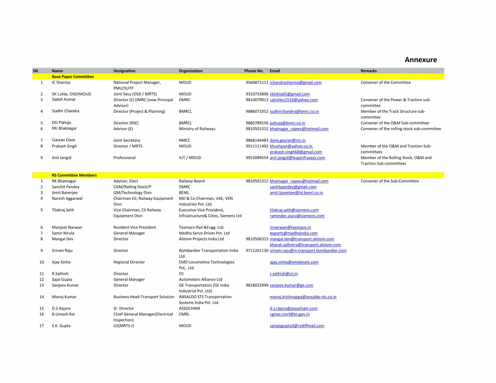
Annexure
SN Name Designation Organization Phone No. Email Remarks
Base Paper Committee
1 IC Sharma National Project Manager,
PMU/SUTP
MOUD 9560871111 [email protected] Convener of the Committee
2 SK Lohia, OSD/MOUD Joint Secy (OSD / MRTS) MOUD 9310733896 [email protected]
3 Satish Kumar Director (E) DMRC (now Principal
Advisor)
DMRC 9810079013 [email protected] Convener of the Power & Traction sub-
committee
4 Sudhir Chandra Director (Project & Planning) BMRCL 9886073352 [email protected] Member of the Track Structure sub-
committee
5 DD Pahuja Director (RSE) BMRCL 9880789156 [email protected] Convener of the O&M Sub-committee
6 RK Bhatnagar Advisor (E) Ministry of Railways 9810501312 [email protected] Convener of the rolling stock sub-committee
7 Gaurav Dave Joint Secretary NMCC 9868144483 [email protected]
8 Prakash Singh Director / MRTS MOUD 9911111492 [email protected]
Member of the O&M and Traction Sub-
committees
9 Anil Jangid Professional IUT / MOUD 9953089554 [email protected] Member of the Rolling Stock, O&M and
Traction Sub-committees
RS Committee Members
1 RK Bhatnagar Advisor, Elect Railway Board 9810501312 [email protected] Convener of the Sub-Committee
2 Sanchit Pandey CGM/Rolling Stock/P DMRC [email protected]
3 Amit Banerjee GM/Technology Divn BEML [email protected]
4 Naresh Aggarwal Chairman CII, Railway Equipment
Divn
MD & Co-Chairman, VAE, VKN
Industries Pvt. Ltd.
5 Tilakraj Seth Vice Chairman, CII Railway
Equipment Divn
Executive Vice President,
Infrastructure& Cities, Siemens Ltd
6 Manjeet Narwan Resident Vice President Texmaco Rail &Engg. Ltd. [email protected]
7 Samir Nirula General Manager Medha Servo Drives Pvt. Ltd [email protected]
8 Mangal Dev Director Alstom Projects India Ltd. 9810506313 [email protected]
9 Sriram Raju Director Bombardier Transportation India
Ltd.
9711261130 [email protected]
10 Ajay Sinha Regional Director EMD Locomotive Technologies
Pvt,. Ltd
11 R.Sathish Director CII [email protected]
12 Sajal Gupta General Manager Autometers Alliance Ltd
13 Sanjeev Kumar Director GE Transportation (GE India
Industrial Pvt. Ltd)
9818022949 [email protected]
14 Manoj Kumar Business Head-Transport Solution ANSALDO STS Transportation
Systems India Pvt. Ltd.
15 D.S.Rajora Sr. Director ASSOCHAM [email protected]
16 B.Umesh Rai Chief General Manager(Electrical
Inspection)
CMRL [email protected]
17 S.K. Gupta US(MRTS-I) MOUD [email protected]

18 Shalabh Tyagi Director/PE+Metro RDSO
19 Anil Kumar System head L&T (Hyderabad) Metro rail. 8008355335 [email protected]
20 Anil Jangid Professional IUT / MOUD 9953089554 [email protected]
21 D.D Pahuja Director BMRCL 9880789156 [email protected]
Traction & Power Committee
1 Satish Kumar Director (Elect) (now Principal
Advisor)
DMRC 9810079013 [email protected] Convener of the Sub-Committee
2 R.N.Lal Advisor (Elect) DMRC 9560046994 [email protected]
3 Sumit Chatterjee Advisor to OSD (UT) MOUD
4 Sujeet Mishra Director/TI RDSO 9794863250 [email protected]
5 S.Ramasubbu CGM/Elect CMRL [email protected]
6 B.G.Mallya CEE/Traction BMRCL 9449874432 [email protected]
7 Anil Jangid Professional IUT / MOUD 9953089554 [email protected]
8 Mangal Dev Director Alstom Projects India Ltd. 9810506313 [email protected]
9 Anupam Arora Chief Manager Marketing /
Smartgrid-Rail electrification
Siemens Limited 9810708127 [email protected]
10 Ms Reeti Sujith Executive Officer CII
11 Samir Narula General Manager Medha Servo Drives Pvt. Ltd [email protected]
12 S.V.R.Srinivas Additional Municipal
Commissioner
MMRDA
13 Dr. Rajiv Kumar Secretary General FICCI
14 D.S.Rawat Secretary General ASSOCHAM
O&M Committee
1 DD Pahuja Director (RSE) BMRCL 9880789156 [email protected] Convener of the Sub-Committee
2 AK Gupta CGM (now Director) DMRC 9971396156 [email protected]
3 Prakash Singh Director / MRTS MOUD 9911111492 [email protected]
4 Deen Dayal Under Secretary MOUD 9810871851 [email protected]
5 Salabh Tyagi Director (PE) RDSO
6 Sujit Mishra Director (TI) RDSO 9794863250 [email protected]
7 Alok Katiyar Director (Signaling) RDSO
8 Anil Kumar Saini System Head L&T (Hyderabad) Metro rail. 8008355335 [email protected]
9 Anil Jangid Professional IUT / MOUD 9953089554 [email protected]
10 Parveen Kumar Sr Vice President RMGL 9810598144 [email protected]
11 Keshava Prasad GM / Rail System Siemens / FICCI
12 R. Satish Director CII [email protected]
13 D.S Rawat Secretary ASSOCHAM
Signalling Committee
1 Raj Kumar Director (Op) (now Advisor) DMRC Convener of the Sub-Committee
2 Arvind Bhatnagar ED/S&T Ministry of Railways
3 Prakash Singh Director MRTS MOUD
4 Rachna Kumar Under Secretary (MRTS-IV) MOUD
5 PK Krishnan Dy CE (Signaling) BMRCL
6 Dr. A.K. Agarwal, CEO Autometers (ASSOCHAM)
7 N. Datta DGM / Marketing Autometers (ASSOCHAM)
8 Sanjeev Kumar Director / Sales General Electric (ASSOCHAM)

9 Manoj Kumar Head (BD) Ansaldo (ASSOCHAM)
10 Kaushal Gupta Executive ASSOCHAM
11 Sajal Gupta Head ASSOCHAM
12 Manish Agarwal General Manager Siemens (CII)
13 Claudio Tiraferri Head (RCS) Bombardier (CII)
14 Jojo Alexander Managing Director ALSTOM (CII)
15 Alok Sinha Head (BD) Invensys (CII)
16 V.G.Ramesh Kumar, Key Account Manager (Railways) Thales (CII)
17 Reeti Sujith Executive CII
18 Binu Kwatra Additional Director FICCI
19 Anil Kumar Saini System Head L&T (Hyderabad) Metro rail. 8008355335 [email protected]
Fare System Committee
1 RK Singh Director (UT) MOUD 9971182160 [email protected] Convener of the Sub-Committee
2 Brajendra Kumar Bangalore Metro Rail Corporation
Ltd.
3 Prashant Rao Delhi Metro Rail Corporation
4 T.M. Shridhar Chennai Metro Rail Ltd.
5 Kaustav Mandal CRIS Kolkata
6 UC Pudia Ahmedabad Municipal Corporation
7 Deepak Kumar UTIITSL, N. Delhi
8 Ashok Chandra Chander Kolkata Metro Rail Corporation
9 Dr. A.K. Garg D/o Electronics and IT
10 Rajesh Narang D/o Electronics and IT
11 A.K. Das Centre for Development of
Telematics
12 D.S. Pathania M/o Road Transport and Highways
13 Deepak Saxena National Highway Authority of
India
Track Structure Committee
1 Pradeep Kumar Advisor Ministry of Railways Convener of the Sub-Committee
2 KK Agrawal ED (Works Planning) Ministry of Railways
3 Representative ED (B&S) RDSO
4 Representative Dy Secretary (MRTS) MOUD
5 AK Singhal Executive Director DMRC
6 Representative BMRCL
7 Representative CMRL
8 Anil Kumar Saini System Head L&T (Hyderabad) Metro rail. 8008355335 [email protected]
