standard test method for evaluation of automotive engine
TRANSCRIPT

Designation: D 5844 – 98 An American National Standard
Standard Test Method forEvaluation of Automotive Engine Oils for Inhibition ofRusting (Sequence IID) 1
This standard is issued under the fixed designation D 5844; the number immediately following the designation indicates the year oforiginal adoption or, in the case of revision, the year of last revision. A number in parentheses indicates the year of last reapproval. Asuperscript epsilon (e) indicates an editorial change since the last revision or reapproval.
1. Scope
1.1 This test method covers a laboratory engine test proce-dure, utilizing a 1977 350 in.3 displacement (5.7 L) OldsmobileV-8 engine. The procedure, using leaded gasoline, evaluatesthe rust inhibition characteristics of engine oils. The testmethod was designed to relate particularly to short-trip serviceunder typical winter conditions in the upper midwestern UnitedStates. The procedure has been correlated with vehicles, usingleaded gasoline, in that type of service and prior to 1978,2
particularly with regard to rusting. It is one of the test methodsrequired to evaluate oils intended to satisfy the API SJcategory.3
1.2 Information Letters are published occasionally by theASTM Test Monitoring Center4 (see Appendix X1) to updatethe test method. Copies of these letters can be obtained bywriting the Center.1.3 The method may not be applicable for the evaluation of
engine oils if unleaded gasoline is used.1.4 The values stated in inch-pound units are to be regarded
as the standard. The values given in parentheses are forinformation only.1.5 This standard does not purport to address all of the
safety concerns, if any, associated with its use. It is theresponsibility of the user of this standard to establish appro-priate safety and health practices and determine the applica-bility of regulatory limitations prior to use.See Note 1, Note 2,Note 3, Note 6, Note 7, Note 8, Note 9, Note 10, Note 11, Note14, and Note 15.
1.6 A Table of Contents follows:Section
Scope 1Referenced Documents 2Terminology 3Summary of Test Method 4Significance and Use 5Apparatus—Overview 6Reagents and Materials 7Preparation of Apparatus 8
Laboratory Ambient Condition 8.1Assembling the Test Engine 8.2
General Information 8.2.1Cleaning Engine Parts 8.2.2Cylinder Block—Preparation 8.2.3Main Bearings—Installation 8.2.4Pistons—Fitting and Numbering 8.2.5Piston Ring End Gaps—Adjustment 8.2.6Connecting Rod and Piston Assemblies—Installation 8.2.7Connecting Rod Bearings—Installation 8.2.8Camshaft—Installation 8.2.9Harmonic Balancer and Oil Slinger—Installation 8.2.10Engine Front Cover and Seal—Installation 8.2.11Timing Mark Indicator—Modification 8.2.12Oil Pump—Installation 8.2.13Dipstick Tube—Installation 8.2.14Oil Pan—Modification 8.2.15Cylinder Head—Preparation 8.2.16Rocker Arm Deflectors—Installation 8.2.17Valve Lifters—Installation 8.2.18Pushrods—Installation 8.2.19Intake Manifolds—Installation 8.2.20Rocker Covers, Spacers and Gaskets—Installation 8.2.21Water Inlet Adapter—Installation 8.2.22Breather Tube—Installation 8.2.23Thermostat Housing—Installation 8.2.24Fuel Pump and Eccentric—Installation 8.2.25Oil Filter Housing—Installation 8.2.26Oil Sample Line—Installation 8.2.27Ignition System—Installation 8.2.28Carburetor—Installation 8.2.29Accessory Drive Units—Delete 8.2.30Exhaust Manifolds—Installation 8.2.31Engine Flywheel and Guards—Installation 8.2.32Special Parts—Sources 8.2.33Engine Coolant System—Pressure Checking 8.2.34
Installation of the Assembled Engine on a Test Stand 8.3Engine Dynamometer—Installation 8.4
Measurement and Control of Operating Conditions 9Temperature Measurements
General Information 9.1.1Thermocouple Locations 9.1.2
Air-to-Fuel Ratio 9.2Carburetor Air Supply Humidity 9.3Exhaust and Exhaust Back Pressure 9.4Blowby 9.5
1 This test method is under the jurisdiction of ASTM Committee D-2 onPetroleum Products and Lubricants and is the direct responsibility of SubcommitteeD02.B0.01 on Passenger Car Engine Oils.
Current edition approved April 10, 1998. Published November 1998.. Originally published as D 5844 – 95. Last previous edition D 5844 – 97.2 Available from ASTM in Special Technical Publication (STP) 3151 (Part 1).
Also available from the Society of Automotive Engineers (SAE) as Technical PaperNo. 780931. The SAE address is 400 Commonwealth Drive, Warrendale, PA 15096.
3 Information available from the American Petroleum Institute (API) in itspublication API1509 Engine Oil Licensing and Certification System. The APIaddress is 1220 L Street, NW, Washington, DC 20005.
4 Until the next revision of this test method, the ASTM Test Monitoring Centerwill update changes in the test method by means of Information Letters; these canbe obtained from theASTM Test Monitoring Center, 6555 PennAve., Pittsburgh, PA15206-4489. Attention: Administrator. This edition incorporates revisions in allInformation Letters through No. 97–1.
1
AMERICAN SOCIETY FOR TESTING AND MATERIALS100 Barr Harbor Dr., West Conshohocken, PA 19428
Reprinted from the Annual Book of ASTM Standards. Copyright ASTM

SectionCrankcase Pressure 9.6Oil Pressure at the Oil Pump Outlet 9.7Oil Pressure at the Engine Oil Filter 9.8Carburetor Inlet Air Pressure 9.9Intake Manifold Vacuum 9.10Rocker Cover Coolant Pressure 9.11Breather Tube Coolant Pressure 9.12Intake Manifold Crossover Coolant Outlet Pressure 9.13Engine Speed and Load 9.14
Procedure—at Test Start 10External Cooling System—Cleaning 10.1Engine Coolant Jacket—Cleaning 10.2Coolant Charging 10.3Test Oil Charging 10.4.1Engine Startup 10.5
Procedure—During the Test 11Engine Shutdown 11.1Oil Sampling 11.2Checking Oil Samples for Glycol Content 11.3Oil Leveling 11.4Test Periods 11.5Non-scheduled Shutdowns 11.6Data Recorded—Hourly Intervals 11.7Data Recorded—Irregular Intervals 11.8Engine Operating Conditions 11.9
Procedure—at Test End 12Interpretation of Results 13
Engine Disassembly and Elapsed Time 13.1Preparation of Engine Parts for Rating 13.2Rust Rating 13.3Photographs of Test Parts 13.4Permanent Storage of Test Parts 13.5
Report 14Calculation of Rust Results 14.2Lifter Plunger Sticking 14.3Oil Pump Relief Valve Sticking 14.4Oil Consumption 14.5Operational Deviations 14.6
Precision and Bias 15Keywords 16
ANNEXESEngine Test Stand Calibration A1External Engine Cooling System A2External Rocker Cover, Intake Manifold and Breather Tube CoolingSystems
A3
External Oil Cooling System A4External Flushing Tank A5External Coolant Mixing Tank A6External Fuel System A7Engine Coolant Preparation A8Sealing Compound Applications A9Fastener Torque Specifications and Torquing Procedures A10Engine Test Parts A11Coolant Calibration Standards A12Dipstick Calibration A13Calculation of Test Severity Adjustments A14Operational Validity Criteria A15Reporting Test Method Results A16
APPENDIXTest Monitoring Center Information Letters X1
2. Referenced Documents
2.1 ASTM Standards:D 2982 Test Methods for Detecting Glycol-Base Antifreezein Used Lubricating Oils5
D 4175 Terminology Relating to Petroleum, PetroleumProducts, and Lubricants5
D 4863 Test Method for Determination of Lubricity ofTwo-Stroke-Cycle Gasoline Engine Lubricants6
D 5302 Test Method for Evaluation of Automotive Engine
Oils for Inhibition of Deposit Formation and Wear in aSpark-Ignition Internal Combustion Engine Fueled WithGasoline and Operated Under Low-Temperature, Light-Duty Conditions6
E 29 Practice for Using Significant Digits in Test Data toDetermine Conformance With Specifications7
E 1119 Specification for Industrial Grade Ethylene Glycol8
G 40 Terminology Relating to Wear and Erosion9
2.2 Coordinating Research Council:CRC Rust Rating Manual No. 710
3. Terminology
3.1 Definitions:3.1.1 blind reference oil, n—a reference oil, the identity of
which is unknown by the test facility.3.1.1.1Discussion—This is a coded reference oil which is
submitted by a source independent from the test facility.(Sub. B Glossary)11
3.1.2 blowby, n—in internal combustion engines, the com-bustion products and unburned air-and-fuel mixture that enterthe crankcase. (Test Method D 5302)3.1.3 candidate oil, n—an oil which is intended to have the
performance characteristics necessary to satisfy a specificationand is to be tested against that specification.
(Sub. B Glossary)3.1.4 clogging, n—the restriction of a flow path due to the
accumulation of material along the flow path boundaries.(Sub. B Glossary)
3.1.5 corrosion, n—the chemical or electrochemical reac-tion between a material, usually a metal surface, and itsenvironment that can produce a deterioration of the materialand its properties. (Sub. B Glossary)3.1.6 non-reference oil, n—any oil other than a reference
oil; such as a research formulation, commercial oil or candidateoil. (Sub. B Glossary)3.1.7 nonstandard test, n—a test that is not conducted in
conformance with the requirements in the standard testmethod; such as running on an uncalibrated test stand, usingdifferent test equipment, applying different equipment assem-bly procedures, or using modified operating conditions.
(Sub. B Glossary)3.1.8 operationally valid standard test, n—in automotive
lubricant testing, a standard test that meets operational validityrequirements, where specified.3.1.8.1Discussion—Operational validity is determined af-
ter a test is completed. Requirements can include (1) mid-limitranges for the average values of primary and secondaryparameters that are narrower than the specified control ranges,(2) allowable deviations for primary and secondary parametersfrom the specified control ranges, (3) downtime limitations,and (4) special parameter limitations.
5 Annual Book of ASTM Standards, Vol 05.02.6 Annual Book of ASTM Standards, Vol 05.03.
7 Annual Book of ASTM Standards, Vol 14.02.8 Annual Book of ASTM Standards, Vol 15.05.9 Annual Book of ASTM Standards, Vol 03.02.10 Available from the Coordinating Research Council, Inc., Perimeter Center
Pkwy., Atlanta, GA 30346.11 Available from the Secretary of the ASTM D02.B0 Subcommittee. The
secretary is Mr. J. L. Newcombe, Exxon Chemical Co., 26777 Central Park Blvd.,Ste. 300, Southfield, MI 48076-4172.
D 5844
2

3.1.9 reference oil, n—an oil of known performance char-acteristics, used as a basis for comparison.3.1.9.1Discussion—Reference oils are used to calibrate
testing facilities, to compare the performance of other oils, orto evaluate other materials (such as seals) that interact withoils. (Sub. B Glossary)3.1.10 rust, n—of ferrous alloys, a corrosion product con-
sisting primarily of hydrated iron oxides.(Sub. B Glossary)3.1.11 scoring, n—in tribology, a severe form of wear
characterized by the formation of extensive grooves andscratches in the direction of sliding. (Terminology G 40)3.1.12 scuff, scuffıng, n— in lubrication, damage caused by
instantaneous localized welding between surfaces in relativemotion which does not result in immobilization of the parts.
(Test Method D 4863)3.1.13 sludge, n—in internal combustion engines, a deposit,
principally composed of insoluble resins and oxidation prod-ucts from fuel combustion and the lubricant, that does not drainfrom engine parts but can be removed by wiping with a cloth.
(Test Method D 5302)3.1.14 standard test, n—a test on a calibrated test stand,
using the prescribed equipment that is assembled according tothe requirements in the test method, and conducted accordingto the specified operating conditions. (Sub. B Glossary)3.1.15 stuck lifter, n— in internal combustion engines, a
lifter plunger that does not return to its original position by itsown force upon removal from the engine.3.1.16 varnish, n—in internal combustion engines, a hard,
dry, generally lustrous deposit that can be removed by solventsbut not by wiping with a cloth. (Test Method D 5302)3.1.17 wear, n—the loss of material from, or relocation of
material on, a surface.3.1.17.1Discussion—Wear generally occurs between two
surfaces moving relative to each other, and is the result ofmechanical or chemical action or a combination of mechanicaland chemical actions. (Test Method D 5302)3.2 Definitions of Terms Specific to This Standard:3.2.1 test start, n—the phrase denoting the installation of
test oil into the engine.
4. Summary of Test Method
4.1 Test Oil and Fuel Requirements:4.1.1 Approximately 2 gal (7.6 L) of test oil are required.4.1.2 Approximately 120 gal (454 L) of test fuel are
required.4.2 Test Stand Calibration—Calibration is required and is
achieved by the laboratory running reference oils supplied bythe ASTM Test Monitoring Center (see Annex A1 for details).4.3 General Procedure:4.3.1 Prior to each test, the engine is completely disas-
sembled, solvent cleaned, measured, and rebuilt in strictaccordance with all furnished specifications.4.3.2 Following this preparation, the engine is installed on a
dynamometer test stand equipped with the appropriate acces-sories for controlling speed, load, and various other engineoperating conditions.4.3.3 The engine is operated continuously for 28 h under
conditions of moderate engine speed, partially warmed-upjacket coolant temperature, and rich air-to-fuel ratio. The
engine is then operated an additional 2 h at aslightly elevatedjacket coolant temperature, with all other conditions un-changed.4.3.4 After the 30 h of operation, the engine is shutdown for
25 min. During this period, spark plugs are changed, andadjustments made to the cooling system controls.4.3.5 The engine is then operated for an additional 2 h under
conditions of relatively high speed and jacket coolant tempera-ture, and lean air-to-fuel ratio.4.3.6 The engine is then disassembled, and specified parts
visually rated to determine the extent of corrosion formed.
5. Significance and Use
5.1 Rust ratings from this test method indicate the tendencyof an oil to permit the formation of corrosion products that caninterfere with hydraulic valve lifter operation, or any otherclose tolerance engine parts, as well as contribute to generalwear problems.5.2 The test method is used in various engine oil specifica-
tions.5.3 The test results are significant only when all details of
the procedure are followed, and operationally valid criteria aredocumented.
6. Apparatus
6.1 The test engine is a 350-in.3 (5.7-L displacement)Oldsmobile V-8 engine with an 8.5:1 compression ratio andequipped with a two-barrel carburetor.12
6.2 The engine is mounted on a test stand and connected toa dynamometer capable of absorbing 100 hp (74.6 kW) at aspeed of 3600 r/min.6.3 An external cooling system is required for the engine,
with a pumping system capable of delivering 60 gal/min (3.79L/s) (see Annex A2 for details).6.4 An external cooling system is required for the jacketed
rocker cover, intake manifold crossover, and breather tubes.This system controls coolant flow, pressure, and temperature inthese engine parts (see Annex A3 for details).6.5 An external oil cooling system is required which in-
cludes a positive displacement pump and a heat exchanger (seeAnnex A4 for details).6.6 Suitable air treatment equipment is required to maintain
the carburetor intake air at constant moisture content andtemperature (see 9.3).6.7 A flushing tank is required to premix and circulate the
cleaning agents (see Annex A5 for details).6.8 Amixing tank is required to premix the glycol and water
coolant (see Annex A6 for details).6.9 A suitable pressurized fuel delivery system is required
(see Annex A7 for details).
7. Reagents and Materials
7.1 General Cleaning Agents—The following have beenfound satisfactory:7.1.1 Aliphatic naphtha with a 300 to 400°F (149 to 204°C)
boiling point.
12 Test engines and various other parts available from the Central PartsDistributor, Bowden Manufacturing Corp., 4590 Beidler, Willoughby, OH 44094.
D 5844
3

NOTE 1—Warning: Combustible. Health hazard.
7.1.2 Oakite 811. 13
NOTE 2—Warning: Combustible. Health hazard.
7.1.3 Oakite 77. 13
7.1.4 Oakite Rust Stripper—O.F. 13
NOTE 3—Warning: Health hazard.NOTE 4—Caution: Some of the Oakite products listed in 7.1.2 to 7.1.4
are alkaline agents used to clean the engine coolant jacket and necessitatethat all aluminum or galvanized materials be removed from contact withthe cleaning agent.
7.2 Organic Solvent—Organic cleaning solution having acomposition of:ethyl acetate 37.5 % volumedenatured alcohol (No. 30) 27.5 % volumebutyl alcohol 5.0 % volumetetrahydrofuran (THF) 30.0 % volume
7.2.1 The THF used shall meet the following specifications:99.5 + % THF, inhibited with 0.025 % butylated hydroxytoluene (BHT), and less than 0.03 % water. Aldrich ChemicalCo. THF,14 catalog number 14722-2, has been found satisfac-tory. The BHT inhibitor limits the potential explosive hazard ofTHF upon drying.
NOTE 5—Warning: Flammable (alcohols). Denatured alcohol cannotbe made nontoxic. Health hazard.NOTE 6—Warning: Combustible (THF). Health hazard.
7.3 Engine Coolant—The engine coolant and the rockercover and breather tube coolant (see Annex A9) consist of amixture of 406 1 % volume ethylene glycol meeting Speci-fication E 1119 for industrial grade ethylene glycol,15 and 6061 % volume distilled water, to which is added 0.25 pt/gal(31.25 mL/L) Pencool 2000 coolant additive.16
NOTE 7—Warning: Combustible (ethylene glycol). Health hazard.
7.3.1 Only the materials from the stated supply sources havebeen found satisfactory.7.4 Test Fuel—The test fuel is certified GMR 995 gaso-
line.17
NOTE 8—Warning: Flammable. Health hazard.
7.4.1 Care shall be taken by purchasers of GMR 995gasoline that all tanks used for transportation and storage areadequately cleaned before being filled with the test fuel.7.5 Sealing Compounds:
7.5.1 Perfect Seal No. 4 Sealing Compound, 18 (Part No.1050026).7.5.2 No. 2 Non-Hardening Permatex.19
7.5.3 3M Super Weatherstrip Adhesive20 (Part No. 051135-08001).7.5.4 Anti-Seizure Compound, such as Fel-Pro C-10021 or
EM Lubricants Inc. CP-29 Spray or can.22
7.6 Engine Assembly Oil—Engine Test Assembly Fluid, EF41123 (Part No. 47503-8).7.7 Reference Oils—Can be purchased from the ASTM Test
Monitoring Center.4 Send inquiries to the attention of theoperations manager (see Annex A1).7.8 Rust Remover—The composition of the rust remover is
as follows:Phosphoric acid (85 % concentrate) 20 % by volumeDenatured alcohol 40 % by volumeDistilled water 40 % by volume
NOTE 9—Warning: Corrosive (phosphoric acid). Health hazard.
8. Preparation of Apparatus
8.1 Laboratory Ambient Condition:8.1.1 Air from fans or a ventilation system should not be
permitted to blow directly on the test engine.8.1.2 Do not use heat lamps or insulation for temperature
control.8.1.3 The ambient laboratory atmosphere should be rela-
tively free of contaminants.8.1.4 It is recommended that the atmosphere in the engine
buildup areas be filtered and controlled for temperature andhumidity to minimize accumulation of dirt or rust on engineparts.8.1.4.1 Uniform temperature control also aids in measuring
and selecting parts for assembly.8.1.5 Engines assembled in a controlled environment area
and moved to a non-controlled storage area, should be pro-tected so moist air cannot enter the engine and promote pretestcorrosion.8.2 Assembling the Test Engine:8.2.1 General Information:8.2.1.1 Use standard General Motors service parts and
buildup procedures as outlined in the 1977 Oldsmobile PartsBook and the Service Manual23 unless special or modifiedparts or procedures are specified. Make pertinent measure-ments of the cylinders, pistons, journals, bearings, and valvetrain to ensure conformance to the test method’s specifications.
13Oakite materials are available from Oakite Products, Inc., 50 Valley Rd.,Berkeley Heights, NJ 07922. However, when ordering Oakite Rust Stripper, specifyOakite Rust Stripper O.F., and order from Wrico Corp., 4835 Whirlwind, SanAntonio, TX 78217.
14 THF is available from Aldrich Chemical Co., 1001 W. St. Paul Ave.,Milwaukee, WI 53233.
15 Available from Chemcentral, 1107 E. Southcross, San Antonio, TX 78223.16 The sole source of supply of Pencool 2000 known to the committee at this time
is The Penray Companies, Inc., 1801 Estes Ave., Elk Grove, IL 60007. If you areaware of alternative suppliers, please provide this information to ASTM Headquar-ters. Your comments will receive careful consideration at a meeting of theresponsible technical committee, which you may attend.
17Direct purchase orders to Phillips 66 Oil Co., Philter Marketing Service, P.O.Box 968, Borger, TX 79008.
18Order part No. 1050026 (available in 40 oz, pt, or gal containers) from AlliedTechnology, Inc., P.O.B. Sealants Division, 11102 Kenwood Rd., Cincinnati, OH45242.
19 Available from local distributors of Permatex products. Contact Permatex Co.,Inc., (Loctite Corp.), 18731-T Cranwood Pkwy., P.O. Box 7183, Cleveland, OH44128, for distributor names in your locality.
20Order part No. 051135-08001 from Minnesota Mining and Manufacturing Co.,AC & S Division, Dept. TR, 3M Center 223-6 N.E., St. Paul, MN 55101.
21 Available from Fel-Pro, Inc., 7450 N. McCormick Blvd., Skokie, IL 60076.Also available from E/M Lubricants, Inc., 6940 Farmdale, N. Hollywood, CA91605.
22Refer to Engine Test Assembly Fluid, EF 411 No. PN 47503-8 when orderingfrom Mobil Oil Corp., Illinois Order Board, P.O. Box 66940, AMF-O’Hare, IL60666.
23 Available from local General Motors Corp. dealers.
D 5844
4

8.2.1.2 To avoid contamination of rated surfaces (hydraulicvalve lifters, oil pump relief valve, and pushrods), handle theseengine parts with gloved hands at all times, particularly duringassembly as well as at the end of the test.8.2.1.3 Sealing compound application information is de-
tailed in Annex A9.8.2.1.4 Fastener torque specifications and torquing proce-
dures are detailed in Annex A10.8.2.1.5 The classification of engine test parts is provided in
A11.1.8.2.1.6 Procurement and usage of engine test parts are
discussed in A11.2.8.2.1.7 New parts required for each test are shown in Annex
A11.3 .8.2.1.8 Parts replaced as necessary are shown in Annex
A11.4 .8.2.2 Clean All Engine Parts:8.2.2.1 Before using a new block, physically remove all slag
and sand deposits contained in the water jacket with asharp-ended 0.25-in. (6.4-mm) diameter drill rod.8.2.2.2 Tap the oil filler tube hole with a3⁄4-in. NPT tap.8.2.2.3 Whether using a new or used block, remove the
crankshaft, main bearings, camshaft bushings, and oil galleryplugs.8.2.2.4 Clean block by applying Oakite 811 to cylinder
walls, and other areas, with a paint brush.Do not submergethe block in Oakite 811. Do not allow the Oakite 811 toenter the engine jacket cooling areas.8.2.2.5 Remove the Oakite 811 by spraying with aliphatic
naphtha that has a boiling point between 300 to 400°F (149 to204°C). Blow dry with air.8.2.2.6 Care should be taken to prevent the attack of
nonferrous materials when using Oakite 811.8.2.2.7 An alternate method of cleaning the block is to
immerse it in a heated chloroethane VG (inhibited 1,1,1,trichloroethane) bath. In this case, the cleaning solution can becirculated through the oil passages to ensure removal ofdeposits.8.2.2.8 If a heated bath or approved pressure washing
system is used, clean all parts afterwards using Oakite 811 andaliphatic naphtha. Allow block to cool before performingfurther assembly steps.8.2.2.9 Degrease all other engine parts in either a heated
bath; or brushing with Oakite 811, followed by spraying withaliphatic naphtha.8.2.2.10 Immediately after cleaning, oil all parts except the
block, using EF-411 fluid.8.2.3 Cylinder Block Preparation:8.2.3.1 Install a solid plug (Part No. 22527020) in the rear
oil gallery. Some engines may already have this modification.8.2.3.2 Replace the freeze plugs. A helpful tool for this
purpose is shown in print RX-117622-B.8.2.3.3 Prestress the block before honing:(a) The honing adapter plate, shown in print RX-117520-D,
is required. The RX prints are available through the TMC.(b) Use new head gaskets (Part No. 12355889) with the
adapter plate each time an engine block is honed. Since thesesame head gaskets are to be used for engine assembly, they
should be markedright andleft so that they can be installed inexactly the same way they were positioned during honing.(c) Use special bolts (Part No. 9409054) in connection with
washers, as shown in print RX-117636-A, to bolt the honingadapter plate to the engine block. Torque these bolts in thesame sequence as indicated in the 1977 Oldsmobile ServiceManual (Fig. 6A3-29). Torque the bolts three times: first, at100 lbf·ft (136 N·m), second at 110 lbf·ft (149 N·m), and thirda repeat at 110 lbf·ft (149 N·m).8.2.3.4 Hone The Cylinder Walls:(a) Sunnen CK-10 or Sunnen CV-61624 honing machines
have been found suitable.(b) The appropriate machine setup is as follows:
CK-10 CV-616spindle speed 155 r/min 170 r/minstroke rate 46 strokes/min 57 strokes/minfeed ratchet 3 or 30 tooth gear 2 or 3
(c) These speeds and stroke rates provide the required 30 to40° maximum cross-hatch pattern. Equip the honing machinewith a fiber mat, part CV-1100.(d) The flow rate of the honing lubricant (Sunnen CK-5024)
should be controlled at 2 gal/min (0.13 L/s).(e) The honing fluid should not contain an excessive amount
of honing debris. In addition, no solvents are to be introducedinto the honing fluid or used to clean the honing stones orguides; clean honing stones or guides only with honing fluid.(f) The cylinders should be honed without main bearings,
but with all main bearing caps in place and torqued. Bearingcaps Nos. 1 through 4 should be torqued to 80 lbf·ft (108 N·m),and No. 5 should be torqued to 100 lbf·ft (136 N·m).(g) The following stones and resulting finish are recom-
mended:Roughening Finishing
stone JHU 52524 JHU 82024
microfinish (AA) 0.51 to 0.76 µm(20 to 30 µin.)
0.23 to 0.28 µm(9 to 11 µin.)
NOTE 10—Once the meter readings have been established which willproduce the above micro-inch finishes using a particular honing machine,it is recommended that those same meter readings be used with thatmachine for future honing jobs.
(h) Hone the cylinder walls so that no more than 0.0004 in.(0.010 mm) difference exists at any point of measurement inthe piston ring travel area. Essentially zero taper should alsoexist in this area.(i) Do not bore cylinder blocks oversize.(j) After honing, clean the engine block again using Oakite
811 and aliphatic naphtha only.8.2.4 Install Main Bearings:8.2.4.1 Use production main bearings. Bearings can be
reused.8.2.4.2 Use Plastigage to check bearing clearances. Num-
bers 1 through 4 main bearing clearances should be 0.0005 to0.0021 in. (0.0127 to 0.0533 mm), and the rear main bearingclearance should be 0.0015 to 0.0031 in. (0.0381 to 0.0787mm). Undersize bearings in steps of 0.0005 in. (0.0127 mm)are available to obtain the specified clearances.
24 Available from Sunnen Products Co., 7910 Manchester Ave., St. Louis, MO63143.
D 5844
5
8.2.4.3 Crankshaft end play should be between 0.004 and0.008 in. (0.102 and 0.203 mm).8.2.4.4 Torque bearings Nos. 1 through 4 to 80 lbf·ft (108
N·m), and bearing No. 5 to 100 lbf·ft (136 N·m).8.2.5 Piston Fitting and Numbering:8.2.5.1 Fit pistons to cylinders as described in the Oldsmo-
bile Service Manual (page 6A3-24 (Fig. 6A3-53)).8.2.5.2 The maximum permissible cylinder wall-to-piston
clearance is defined as a fit resulting in a 3-lb (13.3-N) pullwith a 0.005-in. (0.127-mm) gage.8.2.5.3 Use only the specified pistons and piston ring set;
Central Parts Distributor12 (CPD) parts BX-214-1 and BX-215-1, respectively.8.2.5.4 Number pistons with odd numbers in the left bank
from front to rear and with even numbers in the right bank fromfront to rear (the same numbers appear on the intake manifoldlegs at the cylinders).8.2.5.5 Take extreme care when installing the connecting
rods on the piston wrist pins in order to avoid piston pindistortion, to ensure proper connecting rod to piston pinalignment, and to allow the rod to move freely.8.2.6 Adjust Piston Ring End Gaps:8.2.6.1 For a laboratory setting up this test for the first time,
and using a new engine, it is recommended that a top andsecond end ring gap (suggest using ring gap feeler gage,25 PartNo. X467X) of 0.022 and 0.020 in. (0.56 and 0.51 mm)respectively. The compression ring gaps can be modified insubsequent tests to assist in controlling blowby rates.8.2.6.2 A Sanford SG-48 Ring Grinder,26 or a manufactured
ring grinder (see prints RX-116728-C through 116733-A,116933-E through 116949-A, 116951-A through 116957-A,and 117052-C, 117506-B, and 117507-B) is helpful in grindingthe ring ends to obtain a square-edged gap.8.2.6.3 To measure ring end gaps, position rings in the
appropriate cylinder bore using a piston ring depth gage (printRX-117329-B). Remove any burrs from the rings with a finestone prior to installation.8.2.7 Install Connecting Rod and Piston Assemblies in the
Cylinders:8.2.7.1 Oil cylinder walls with EF 411 oil and wipe with a
clean, soft cloth. Repeat process until there are no honing orgrinding particles left on the cloth. Change cloths frequently.As the final step, re-oil the cylinder walls with EF 411.8.2.7.2 Use a piston ring expander tool for installing the
piston rings. A Perfect Circle 4.0625 ring expander tool27 (PartNo. P401-K) has been found satisfactory for this purpose.8.2.7.3 Align piston rings as described on print RX-
117372-C prior to installing the pistons in the cylinders.8.2.7.4 Use a Snap-on ring compressor tool (RC-40C or
equivalent) to compress the rings, and slide the connecting rod
and piston assemblies carefully into the correct cylinders.8.2.8 Install Connecting Rod Bearings:8.2.8.1 Use connecting rod bearings, Part No. 18008494.
Bearings can be reused.8.2.8.2 The bearing clearance shall be between 0.0004 and
0.0033 in. (0.010 and 0.084 mm).8.2.8.3 The side clearance shall be between 0.006 and 0.020
in. (0.152 and 0.508 mm).8.2.8.4 Bolts on Nos. 5 and 6 connecting rods shall be no
longer than 2.375 in. (60.33 mm).8.2.9 Install Camshaft:8.2.9.1 Modify the front camshaft bearing (Part No.
12339842) as shown in print RX-118211-C. The machinedgroove from the oil hole to the front edge of the bearingprovides an oil feed to the thrust washer.8.2.9.2 When camshaft bearings are replaced, a Burroughs
cam bearing installation tool28 (Part No. BT6409, or equiva-lent) is recommended.8.2.9.3 Remove any nicks, burrs, or ridges on the thrust face
of the camshaft (Part No. 562299) by light filing.Do notmachine the surface nor remove significant material, as thismay alter the thrust face to lifter dimension.8.2.9.4 A thrust washer as shown on print RX-118213-A is
required between the thrust surfaces of the camshaft and theblock. A thrust washer can be used more than once, if in goodcondition; however, if reused, position the same side of thethrust washer toward the block as previously.8.2.9.5 Replace the camshaft timing gear (Part No. 381263)
at least every second test.8.2.9.6 Modify the camshaft gear bolt as shown in print
RX-117228-A.8.2.9.7 A timing gear oil deflector and washer are required
as shown on prints RX-118306-A and RX-117464-A.8.2.10 Install Harmonic Balancer and Oil Slinger:8.2.10.1 Deburr the harmonic balancer keyway slot and the
slot on the crankshaft with a mill file, and modify as shown inprint RX-118317-B. The inside diameter of the bore on theharmonic balancer can be reamed to 1.50 in. (38.1 mm) tofacilitate installation and removal. The harmonic balancershould also be checked to ensure that no slippage has occurredbetween the hub and the outer flange.8.2.10.2 The production oil slinger (Part No. 382572) may
not provide sufficient clearance between the front cover and theharmonic balancer. An additional spacer washer as shown inprint RX-117382-A can be used to shim the harmonic balancerout from the front cover.8.2.11 Install the Engine Front Cover and Seal:8.2.11.1 Replace the front cover and water pump assembly
with the front cover shown in print RX-117224-D.8.2.11.2 Use the production front seal (Part No. 552711),
and this can be installed using a seal driver shown in printRX-117370-B.8.2.11.3 Attach the front cover oil deflector, shown in print
RX-117319-B, to the front cover.8.2.11.4 Use the production front cover gasket (Part No.
22547856).
25 Part No. X467X, with a range of 0.508 to 1.27 mm (0.020 to 0.050 in.) by0.0259 mm (0.001 in.) increments, available from Sterling Supply Co., 1220 EastNine Mile Rd., Ferndale, MI 48220.
26 Sanford SG-48 (with Oldsmobile 350 head) can be ordered from SanfordManufacturing Co., P.O. Box 318, Roselle, NJ 07203.
27 The following Perfect Circle tools and seals: 4.0625 in. ring expander tool(Part No. P401-K), valve stem seals (Part No. 55A397), and valve stem sealinstallation tool (Part No. 55A396) are available from Engine Products Division,Dana Corp., P.O. Box 1166, Richmond, IN 47374.
28 Available from Burroughs Tool and Equipment Co., 2429 N. Burdick St.,Kalamazoo, MI 49002.
D 5844
6

8.2.12 Timing Mark Indicator:8.2.12.1 Modify the timing mark indicator in accordance
with print RX-118318-A.8.2.12.2 Dowel the indicator to the front cover to ensure
proper alignment.8.2.13 Install Oil Pump:8.2.13.1 Use a new oil pump for each test. Pumps are
available (Part No. BX-211-1 or BX-211-2) through theCentral Parts Distributor,12 and are supplied with all necessaryhardware, excluding the relief valve.Use no abrasive materialsduring cleaning, and do not make modifications to any part ofthe assembly.8.2.13.2 The oil pump relief valve is available from the
CPD (Part No. BX-201-1).Use the valve as received with nomodifications to the surface finish.8.2.13.3 Wash the valve with aliphatic naphtha and oil with
EF 411 prior to installation.8.2.13.4 The cleaned valve should have a numerical rating
of 9.7 using the Coordinating Research Council (CRC) RatingManual No. 7.8.2.13.5 The oil pump relief valve spring can be stretched or
trimmed to vary oil pressure. Up to three coils can extendbeyond the housing with the relief valve seated.8.2.14 Install Dipstick Tube:8.2.14.1 Install a dipstick tube using a driver conforming to
print RX-117348-B. Check the position of the tube with a gageshown in print RX-117326-B. Note position at cylinder headfor manifold clearance.8.2.14.2 No dipstick is used for the test. Use a dipstick tube
cap, shown in print RX-117349-A, during the test.8.2.15Oil Pan—Modify the oil pan (Part No. 555137) as
shown on print RX-118305-D.8.2.15.1 Install the special oil pan baffle shown on print
RX-118332-B.8.2.16 Cylinder Head Preparation:8.2.16.1 Deburr all mating surfaces of the cylinder heads to
the block and manifolds with a 12-in. (30.5-cm) smooth file toensure gasket seating.8.2.16.2 Machine the outside diameter of all valve guides to
0.5316 0.007 in. (13.496 0.18 mm) using a valve guidecutter.29
(a) Machine the guides until the cutter touches the top of theguides (approximately 0.38 in. [9.53 mm]).Do not machine thetop of the guide.(b) Be sure that the guides are machined all around (360°)
and have no nicks or grooves.(c) Use an11⁄32-in. (8.73-mm) pilot with the cutting tool.
Check the pilot periodically for wear. No excessive clearanceshould exist between the pilot and the valve bores.8.2.16.3 Thoroughly clean cylinder heads with Oakite 811
solvent, followed by spraying with aliphatic naphtha, andair-blow dry.8.2.16.4 Install the cup-type freeze plugs (Part No. 380254)
on the cylinder heads. A driver that facilitates the installation isshown on print RX-117377-A.
8.2.16.5 All valves should be lightly lapped with fine gritlapping compound to improve seating (before seals are in-stalled).8.2.16.6 Use new valve stem seals (Part No. BX-216-1)12
for 11⁄32-in. (8.73-mm) diameter valve stems on both intake andexhaust valves.8.2.16.7 Install the seals using the plastic shields, to protect
the seals from damage, and an installation tool (Part No.53A396),27 to ensure proper seating.8.2.16.8 Use Part No. BX-213-112 valve springs. These
springs are protected with red oxide primer by the manufac-turer.8.2.17 Valve Lifters:8.2.17.1 Do not remove the oil in the hydraulic valve
lifters12 (Part No. BX-202-1).8.2.17.2 Oil the lifter bodies with EF-411 oil prior to
installation.8.2.17.3 Number the left bank lifters with odd numbers
from front to rear, and the right bank with even numbers fromfront to rear.8.2.18 Pushrods:8.2.18.1 Use the pushrods12 (Part No. BX-210-1) as re-
ceived from the CPD.8.2.18.2 Clean the pushrods with aliphatic naphtha, air-dry,
and oil with EF-411 oil prior to installation.8.2.19 Rocker Arm Pivots:8.2.19.1 Use rocker pivots (Part No. 391208) for cylinder
numbers 1, 2, 7, and 8.8.2.19.2 Use rocker pivots (Part No. BX-221-1) for cylin-
ders 3, 4, 5, and 6.8.2.20 Rocker Cover Deflectors:8.2.20.1 Use four stud-type bolts (Part No. 556931) for
mounting the rocker cover deflector stanchions shown on printRX-117288-A.8.2.20.2 Attach the rocker cover deflectors shown on print
RX-117289-B, (modified) to the stanchions using the specifiedbolts (Part No. 388708).8.2.21 Intake Manifold:8.2.21.1 Modify the intake manifold crossover, as shown on
prints RX-118315-D, RX-117813-A and RX-118316-A, topermit the circulation of coolant per print RX-117928-C.8.2.21.2 Plug the heater water outlet hole located at the right
rear corner and the temperature sensor hole on the left frontcorner.8.2.21.3 Remove the choke stove from the manifold, and
install a plate conforming to print RX-117813-A using a gasket(Part No. 382709).8.2.21.4 Deburr all mating surfaces of the intake manifolds
to cylinder heads with a 12-in. (30.5-cm) smooth file to ensuregasket seating.8.2.21.5 Use special intake manifold gaskets12 (Part Nos.
BX-204-1 [left] and BX-205-1 [right]).8.2.22 Rocker Cover, Spacers and Gaskets:8.2.22.1 Install rocker cover spacer-to-head gaskets30 (Part
No. 393573) on the cylinder heads using Perfect Seal No. 4Sealing Compound.
29 TRW No. VP-503 for11⁄32 in. can be ordered from TRW Valve Division, 8001E. Pleasant Valley, Cleveland, OH 44131. Also available as Crane No. 97017 for11⁄32 in. from Crane Cams, Inc., 100 N.W. 9th Terrance, Hallandale, FL 33009.
30 These gaskets are manufactured semiannually (order cut-off dates are January1 and July 1). Order from Crotty Corp., 848 W. Chicago, Quincy, MI 49082.
D 5844
7

8.2.22.2 Attach rocker cover spacers conforming to printRX-118304-D to the head using 0.875 in. (22.2 mm)1⁄4 by 20socket head cap screws coated with 3M Super WeatherstripAdhesive.8.2.22.3 Install the cork rocker cover gasket (Part No.
573396) on the rocker cover side of the spacer with 3M SuperWeatherstrip Adhesive.8.2.23Water Inlet Adapter:8.2.23.1 Use a water inlet adapter conforming to that shown
on print RX-118315-D and in conjunction with a gasket (PartNo. 382927).8.2.23.2 Quick disconnect full-opening fittings31 such as
shown on prints RX-118137-C and RX-118136-A can also beused.8.2.24 Breather Tube—Attach a breather tube (Part No.
BX-212-1), available from the CPD, to the front cover using agasket (Part No. 555765).8.2.25 Thermostat Housing—Replace the thermostat hous-
ing with a coolant outlet adapter (fabricated from copper orblack iron), using a gasket (Part No. 22547855), and with asuitable connection as on print RX-117261-A.8.2.26 Fuel Pump and Eccentric:8.2.26.1 Remove and replace the fuel pump with a plate
conforming to print RX-117262-A, and use a gasket (Part No.22505998).8.2.26.2 Remove and replace the eccentric with a deflector
and washer as on prints RX-118306-A and RX-117464-A,respectively.8.2.27Oil Filter Housing:8.2.27.1 Separate the oil filter housing from the engine by
an oil filter block conforming to print RX-117227-A.8.2.27.2 Use gaskets (Part No. 382455, two required), and
Perfect Seal No. 4 Sealing Compound.8.2.28Oil Sample Line—Remove the oil pressure sensing
element located in the front-left corner of the cylinder block,and add suitable plumbing to permit the removal of oilsamples.The oil sample line length should be held to aminimum.8.2.29 Ignition System:8.2.29.1 High energy ignition wire capable of withstanding
moisture and high temperature is required. Delco part 378E, orequivalent, is satisfactory.(a) Use an acceptable spark plug boot removal tool32 (Part
Nos. OTC 7078 or BT 7604) to remove the ignition wires fromthe spark plugs.8.2.29.2 Check the distributor (Part No. 1103259) on a
distributor tester before installing in the engine.(a) Disable the mechanical advance mechanism by tack
welding the advance weights so that no motion is possible.8.2.29.3 Disconnect the vacuum advance unit by removing
the vacuum hose and plugging the vacuum source at thecarburetor, shown on print RX-118319-D.8.2.29.4 Use AC spark plugs (Part No. R46SZ).
(a) Install new spark plugs prior to test startup and at the 30h shutdown.(b) Gap spark plugs with a wire gage to 0.060 in. (1.52 mm).8.2.30 Carburetor—Use a duty cycle controlled carburetor
(Part No. 17111526) to control air to fuel ratio.8.2.30.1 Obtain a carburetor adapter plate (Part No. BX-
260-1) and model 555 timer (Part No. BX-150-1) from theCPD.8.2.30.2 Carburetor settings and build guidelines can be
obtained from GM NAO Research and Development Center.33
8.2.30.3 Disassemble, clean and rebuild carburetors prior toeach sixth test, or more often if air to fuel ratio control becomesa problem.8.2.31 Accessory Drive Units—Use no external drive units,
including alternators, generators, fuel pumps, power steeringunits, air pumps, etc.8.2.32 Exhaust Manifolds:8.2.32.1 Use the left exhaust manifold (Part No. BX-209-1)
on both banks.8.2.32.2 Deburr all mating surfaces of the exhaust mani-
folds to cylinder heads with a 12-in. (30.5-mm) smooth file toensure gasket seating.8.2.32.3 The recommended method for connecting the ex-
haust pipes to the manifolds is shown on print RX-117284-A.8.2.32.4 Locate pressure taps for exhaust back pressure and
exhaust gas analysis in each manifold as shown on printRX-117286-C.8.2.32.5 Stainless steel bolts,3⁄8 by 16 and 1.25-in. (31.8-
mm) long, can be used to fasten the exhaust manifolds to theengine.
NOTE 11—Caution: Exhaust manifolds can warp during engine opera-tion. The sealing surfaces may be reground flat several times to increaseutilization of the manifolds.
8.2.33 Engine Flywheel and Guards:8.2.33.1 Modify the flywheel (Part No. 399071) as shown
on print RX-117225-C.8.2.33.2 The engine flywheel guard shown on print RX-
117167-E and the safety housing shown on print RX-117168-D, facilitate the installation and removal of the engine.8.2.34 Special Parts—In Section 8 there have been refer-
ences to several prints where part fabrication is described.These parts can be ordered from GM33 or made by anymachine shop capable of fabricating the parts exactly accord-ing to the prints.8.2.35 Pressure Checking the Engine Coolant System:8.2.35.1 It has been found advantageous to pressure check
the coolant system before installing the assembled engine onthe test stand.8.2.35.2 Block and pressurize the coolant passages to 30 in.
Hg (101 kPa) and monitor any change in pressure for 10 min.(a) Changes in pressure of less than 1 in. Hg (3.4 kPa) in 10
min are considered satisfactory.(b) Larger changes in pressure necessitate re-torquing or
replacing the cylinder heads, or both; or replacing the intakemanifold gaskets or seals, or both.31 Available from Aeroquip Corp., Industrial Division, 1225 W. Main St., Van
Wert, OH 45891.32 Tool OTC 7078 is available from Owatonna Tool Co., 376 North St.,
Owatonna, MN 55060. Tool BT 7604 is available from Burroughs Tool andEquipment Co., 2429 N. Burdick St., Kalamazoo, MI 49007.
33 Available from GM NAO Research and Development Center, Warren, MI48090. Attention: Sequence Test Coordinator.
D 5844
8

8.3 Install Assembled Engine on Test Stand:8.3.1 Lifting Engine—Lift the assembled engine as de-
scribed in the 1977 Oldsmobile Service Manual (Fig. 6A3-6).Do not lift the engine by the manifold. Glycol coolant leaksmay occur.8.3.2 Engine Mounts—In conjunction with prints RX-
117379-D, RX-117529-D and RX-117990-B, the followingengine mounts are recommended:8.3.2.1 Rear right-hand (Part Nos. 568980 or 31-2138),8.3.2.2 Rear left-hand (Part Nos. 568981 or 31-2139), and8.3.2.3 Front (Part Nos. 572945 or 31-2137).8.3.3 Drive Shaft—A flywheel to driveshaft coupling
adapter shown on print RX-117157-B, can be used in conjunc-tion with a Dana shaft34 (Part No. 1601-1608), and a rubberjoint set (part 206881-20).8.4 Engine-Dynamometer Installation:8.4.1 A typical engine-dynamometer installation is shown
on print RX-117529-D.8.4.2 Mount the engine on the test stand so that the
carburetor mounting flange to intake manifold interface ishorizontal.
9. Measurement and Control of Operating Conditions
9.1 Temperature Measurements:9.1.1 General Considerations:9.1.1.1 Accurate temperature measurement of several oper-
ating conditions is required. Temperature measurement is ofextreme importance and assurance of temperature measure-ment accuracy is mandatory.9.1.1.2 Suitable temperature readout instrumentation with
premium type, sheathed, grounded thermocouples, and pre-mium grade wire shall be used.9.1.1.3 Check all thermocouples for accuracy at the tem-
perature levels at which they are used.(a) This is particularly important for the thermocouples used
in the oil filter block and water jacket.9.1.1.4 Iron-Constantan (Type J) thermocouples are recom-
mended. Conax35 part numbers are as follows:(a) For the oil filter block and breather tube gas—Conax
J-SS-12-G-PJ 1.5 in. (38 mm).(b) For fuel, the coolant outlet and inlet, breather tube
coolant outlet, carburetor air, and intake manifold—ConaxJ-SS-12-G-PJ 2 in. (51 mm).(c) For the rocker cover coolant outlet, and intake manifold
exhaust crossover—Conax J-SS-12-G-PJ 3 in. (76 mm).(d) For the oil pan—Conax J-SS-G-PJ 4 in. (102 mm).9.1.1.5 The recommended thermocouple packing gland for
the above thermocouples is the Conax MPG-125-A-T35 pack-ing gland.9.1.1.6 Accurate location of thermocouples is essential for
acceptable test operation.9.1.2 Specific Thermocouple Locations:9.1.2.1Oil Filter Block—Locate the thermocouple in the
center of the stream of flow (see print RX-117227-A).
9.1.2.2Oil Pan (Sump)—Locate the thermocouple in theright rear corner of the oil sump as shown on print RX-118305-D; it should extend 1.5 in. (38 mm) into the oil pan.9.1.2.3Engine Coolant Out—Locate the thermocouple in
the thermostat housing within 3 in. (76 mm) of the intakemanifold in the center of the stream of flow.9.1.2.4Engine Coolant In—Locate the thermocouple in the
coolant inlet adapter 9 in. (22.9 cm) from the front cover to theinlet adapter interface, as shown on print RX-118135-D. Thethermocouple should be located in the center of the stream offlow.9.1.2.5Rocker Cover Coolant Out—Locate the thermo-
couple within 3 in. (76 mm) of the fitting in the cover. Thethermocouple should be located in the center of the stream offlow.9.1.2.6Breather Tube Coolant Out—Locate the thermo-
couple within 3 in. (76 mm) of the fitting in the breather tube.The thermocouple should be located in the center of the streamof flow.9.1.2.7Blowby Gas—Extend the thermocouple 0.5 in. (12.7
mm) into the stream from the wall, as shown on printRX-117729-C.9.1.2.8 Intake Manifold Exhaust Crossover Coolant
Outlet—Install the thermocouple in a tee fitting in the coolantoutlet close to the intake manifold. The thermocouple shouldbe located in the center of the stream of flow.9.1.2.9Carburetor Air—Locate the thermocouple in the
intake air horn (Part No. BX-395-1). The thermocouple shouldbe located in the center of the stream of flow.9.1.2.10 Intake Manifold Mixture—Install the thermocouple
in the threaded1⁄4in. NPT hole located to the front of thecarburetor and in the center of the Nos. 1 and 4 cylinder legsof the intake manifold. Locate the thermocouple in the centerof the intake mixture stream (approximately 0.75 in. (19.1mm)).9.1.2.11Fuel—Install the thermocouple in a tee fitting in
the fuel line within 2 in. (51 mm) of the carburetor fuel inlet.The thermocouple should be located in the center of the streamof flow.9.2 Air to Fuel Ratio (AFR) Measurement and Control:9.2.1 Determine engine AFR by Orsat analysis or by elec-
tronic gas analysis equipment of the exhaust gases, andcomparing the analyzed values with theoretical values plottedon a chart of exhaust gas component volumes versus AFR (seeFig. 1).9.2.2 Suitable electrical AFR indicating equipment may be
used to provide continuous AFR indications, as long as it isproperly calibrated using appropriate span gases.9.2.3 The electronic fuel mixture control unit (BX-150-1)
can be used to control air-to-fuel ratios.9.2.4 The theoretical relationship between engine exhaust
gas CO2, CO, and O2 contents and AFR is shown on Fig. 1 forfuel with an H to C ratio of 2:1.9.2.4.1 Since the theoretical chart was constructed assuming
complete combustion, it is necessary to correct exhaust gasanalyses that contain either oxygen or carbon monoxide(indicating rich and lean combustion, respectively) beforeusing the figure. The corrections can be made as follows:
34 Available from Dana Corp., Spicer Universal Joint Division, P.O. Box 986,Toledo, OH 43696.
35 Available from Conax Corp., 2302 Walden Ave., Buffalo, NY 14225. Atten-tion: Sales Dept.
D 5844
9

(a) Rich Samples:
observed % CO2 3 100100 – 5~observed % O2!
5 corrected CO2 (1)
observed % CO3 100100 – 5~observed % O2!
5 corrected CO (2)
(b) Lean Samples:
observed %O2 2 0.5 ~observed %CO! 5 correctedO2 (3)
observed %CO2 1 observed %CO5 correctedCO2 (4)
9.2.4.2 Air to fuel ratios obtained from Fig. 1 using thecorrected CO, CO2, and O2 values shall agree within 0.5 ratio.9.3 Carburetor Air Supply Humidity Measurement and Con-
trol:9.3.1 An instrument such as the Alnor 7300 Dewpointer36
can be used to determine the moisture content of the carburetorair.9.3.2 Determination of the dew point should be made at the
test stand.9.3.3 Suitable equipment is needed to maintain the carbu-
retor intake air at a moisture content of 806 5 grains/lb of dryair (11.46 0.7 g/kg of dry air), a dry bulb temperature of 806
2°F (26.76 1.1°C), and a static pressure of 0.1 to 0.3 in. water(24.9 to 74.6 Pa) measured at the carburetor inlet.9.3.3.1 A system, such as shown in prints RX-179649-D
through RX-179653-D, RX-117375-C and RX-117376-C, canbe used to control the moisture content and temperature of thecarburetor air.9.3.4 Maintain the duct surface temperature above the dew
point to prevent condensation (loss of humidity level).9.3.5 A method of controlling the flow of air to the
carburetor is shown on print RX-117162-C.9.3.5.1 Use the intake air horn, Part No. BX-395-1; the
carburetor intake air adapter shown on print RX-118616-E andcorresponding gasket, Part No. BX-361-1; and the carburetoradapter plate, Part No. BX-260-1. Alternatively, the air intakehorn can be fabricated from a print available from the CPD.9.3.5.2 Position the adapter so that the air enters the adapter
from the rear of the engine.9.3.5.3Remove the carburetor intake air horn anytime the
engine is not running and during the timing run.9.3.5.4 Carburetors shall be disassembled, cleaned, and
rebuilt prior to each test, or more often if air-to-fuel ratiocontrol becomes a problem.9.4 Exhaust and Exhaust Back Pressure Measurement and
Control:9.4.1 The use of 4-in. (102-mm) stainless steel exhaust pipe,
Part No. RT10E (Flexonic Corp.)37 has proven satisfactory.9.4.2 Do not add cooling water or spray directly into the
exhaust streams or onto the exhaust pipes.9.4.3 Do not use water-jacketed exhaust pipes on the sec-
tions of the exhaust pipes extending from the exhaust manifoldto the test bed or floor level.9.4.4 Jacketed exhaust pipes or external water spray can be
used on the portions of the exhaust systems extending belowthe test bed or floor level.9.4.5 Measure the exhaust back pressure at the exhaust
sample line location as shown on print RX-117286-C.9.4.6 The back pressure and exhaust sample lines from the
exhaust manifold, their location shown on print RX-117286-C,shall run downhill from the manifolds to traps before theconnection to manometers.9.4.6.1 It is recommended that about 0.75 in (19 mm) of
water (19 mm) be left in the traps to ascertain that a closedsystem exists.9.4.7 Pressure taps are required in each manifold in order to
permit reading the back pressure separately on each bank.9.4.8 Do not connect the sample lines together, in order that
separate samples can be taken from each bank for air-to-fuelratio determinations.9.4.9 The readout device for exhaust back pressure can be
either a manometer or a suitable pressure gage with scalegraduations of 0.1 in. of water (24.9 Pa), and a suggested rangeof zero to 36 in. of water (8.96 kPa).9.4.10 The control system can be either a manual system for
controlling the exhaust back pressure from each bank, or anautomatic system such as shown on print RX-117462-C. A
36Available through local distributors, or Alnor Instrument Co., 97301 N.Caldwell Ave., Niles, IL 60648.
37 Available from local distributors, or Flexonic Division UOP, Inc., 300 E.Devon Ave., Bartlett, IL 60123.
FIG. 1 Air-to-Fuel Ratio Chart
D 5844
10

restriction in one side may be required to permit automaticdifferential pressure control.9.5 Blowby Measurement and Control:9.5.1 Measure blowby at the breather tube outlet with the
crankcase oil filler tube and the dipstick guide tube pluggedand while maintaining the crankcase pressure at 0.05 in. ofwater (0.06 12.4 Pa).9.5.1.1 Crankcase pressure should be stabilized in 6 min or
less. If not, record the blowby rate obtained and include a noteon the Supplemental Operational Data sheet that the crankcasepressure had not stabilized within the 6 min.9.5.2 Use a sharp-edged orifice meter such as shown on
print RX-116169-C33 to measure engine blowby rates.9.5.3 The blowby meter to breather tube connection shall
exist only during the blowby rate determinations. At all othertimes, the blowby gas shall be emitted directly out of thebreather tube top, as shown on print RX-117729-C, into thesurrounding air.9.5.4 This system includes the required surge tank shown on
print RX-117431-C, means to measure blowby gas tempera-ture, and means to maintain crankcase pressure at 0.006 0.05in. of water (0.006 12.4 Pa).9.5.5 A system, such as shown on prints RX-117726-C,
RX-117727-C, RX-117294-A, RX-117730-C and RX-117731-C can be used as an aid in making blowby measure-ments.9.5.6 Report observed data in cfm (L/min) after correcting
for meter calibrations and adjusting these results to 100°F(37.8°C) and 29.7 in. Hg (100 kPa).9.5.7 Refer to 8.2.6.1 for information about controlling
blowby.9.6 Crankcase Pressure Measurement:9.6.1 Measure the pressure with a gage or manometer that
has a range of − 0.5 to 0.5 in. of water (−124 to 124 Pa), ingraduations of no greater than 0.02 in. of water (5.0 Pa).9.6.2 For manual systems, Magnehelic Gage Model No.
230138 is suitable.9.6.3 If a manometer is used in this application, a conden-
sation trap shall be employed to eliminate the possibility ofmanometer fluid accidentally entering the crankcase.9.6.4 For automated blowby systems, a Honeywell Control-
ler 714P2B-31K139 shown on print RX-117727-C has beenfound satisfactory for measuring crankcase pressure. Thiscontroller can be used for pressure measurements up to 0.5 in.of water (124 Pa).9.6.5 For either manual or automated systems, two addi-
tional indicators such as Magnehelic Model No. 2310 andModel No. 2020 (see print RX-117727-C for location) can beused for pressure measurements from 0.5 to 5.0 in. of water(0.124 to 1.24 kPa), and 0 to 20 in. of water (0 to 4.98 kPa),respectively.9.6.5.1 The first indicator shall have a zero center scale and
measure from−0.5 to + 5.0 in. of water (−1.24 to +1.24 kPa),with graduations no greater than 0.5 in. of water (0.124 kPa).
9.6.6 The accuracy of both the low range (06 0.5 in. ofwater (06 0.124 kPa)) and the mid range (06 5.0 in. of water(0 6 1.24 kPa )) pressure indicating devices used by alaboratory shall not be affected by pressure excursions of about5.0 in. of water (1.24 kPa).9.6.7 Pressures exceeding 5.0 in. of water (1.24 kPa) should
be measured and recorded on the 0 to 20 in. of water (0 to 4.98kPa) gage. Record pressures exceeding 20 in. of water (4.98kPa) as + 20.0 in. of water ( + 4.98 kPa).9.7 Oil Pressure at the Oil Pump Outlet—Measurement and
Control:9.7.1 Measure the oil pressure at the location shown on print
RX-117227-A.9.7.2 Measurement of the oil pressure at the oil pump outlet
pressure requires the use of a pressure gage having a scalerange of 0 to 100 psi (0 to 689 kPa), with scale graduations of1 psi (6.9 kPa).9.7.3 Refer to 8.2.13.5 for information about the control of
oil pressure.9.8 Oil Pressure at the Engine Oil Filter—Measurement—
Measurement of the oil pressure at the engine oil filter requiresthe use of a gage having a scale range of 0 to 100 psi (0 to 689kPa), with scale graduations of 1 psi (6.9 kPa).9.9 Carburetor Inlet Air Pressure Measurement and Con-
trol:9.9.1 Measure the air pressure at the carburetor intake air
horn (BX-395-1).9.9.2 The measurement of carburetor inlet air pressure can
be made by either a manometer or a pressure gage. A range of0 to 0.5 in. of water (0 to 124 Pa), and scale graduations of 0.02in. of water (4.98 Pa) are required.9.9.2.1 When using a manometer, a condensate trap should
be installed between the manometer and the air horn to protectagainst the possibility of a momentary interruption of air flowor any other transient condition that might result in manometerfluid entering the engine intake system.9.9.2.2 Measure the pressure at the location provided on the
carburetor intake air horn, Part No. BX-395-1.9.9.3 Refer to 9.3.5 for information about controlling the
inlet air pressure.9.10 Intake Manifold Vacuum Measurement:9.10.1 Install a fitting for the measurement of intake mani-
fold vacuum in the existing1⁄4in. NPT hole located in the centerof the No. 6 and 7 cylinder leg of the intake manifold (to therear of the carburetor).9.10.2 Suitable readout instrumentation with a range of 0.0
to 20 in. Hg (0.0 to 68 kPa) and approximate scale graduationsof 0.1 in. Hg (0.34 kPa) is required.9.11 Rocker Cover Coolant Pressure Measurement and
Control:9.11.1 Measure the pressure at the top front fitting of each
rocker cover as described on print RX-117928-C.9.11.2 A pressure gage with scale graduations of approxi-
mately 1 psi (6.9 kPa) and a range of 0.0 to approximately 15psi (103.5 kPa) is required.9.11.3 Refer to Annex A3 for information about controlling
the rocker cover coolant pressure.9.12 Breather Tube Coolant Pressure Measurement:
38 Available from Dwyer Instrument Co., P.O. Box 373-T, Michigan City, IN46360.
39 Available from Honeywell Inc., Industrial and Automation Div., 1100 VirginiaDr., Ft. Washington, PA 19034.
D 5844
11

9.12.1 Measure the pressure at the coolant outlet fitting ofthe breather tube as shown on print RX-117731-C.9.12.2 A pressure gage with scale graduations of approxi-
mately 1 psi (6.9 kPa) and a range of 0.0 to approximately (15psi) (103.5 kPa) is required.9.13 Intake Manifold Crossover Coolant Outlet Pressure
Measurement:9.13.1 Measure the pressure at the tee installed in the choke
stove adapter plate as shown on print RX-117813-A.9.13.2 A pressure gage with a range of 0 to 15 psi (0 to 6.9
kPa) and scale graduations 1 psi (6.9 kPa) is suggested.9.14 Engine Speed and Load Measurement and Control:9.14.1 Engine speed and load are important test parameters,
and particular attention should be given to achieving andmaintaining accurate calibration of the related instrumentsystems.9.14.2 A typical closed loop control system maintains speed
by dynamometer control, and load by engine throttle control.
10. Procedure (Start of the Test)
10.1 External Cooling System Cleaning:10.1.1 Clean the external cooling system of a new test stand
or new flushing tank assembly, or both, prior to flushing anengine the first time.10.1.2 Remove all aluminum and galvanized materials from
the system.10.1.3 A solution of 5 oz/gal (37.4 g/L) of Oakite 77 in
water heated to 1606 5°F (71.16 2°C) and circulated at themaximum obtainable flow rate for 60 min will clean theexternal system satisfactorily. Follow this cleaning with athorough water flush of all system components.10.1.4 Recleaning of the external cooling system is periodi-
cally required.10.2 Engine Coolant Jacket and Intake Manifold Coolant
Crossover Cleaning (Flushing):10.2.1 After the engine has been installed on the test stand,
chemically clean the engine coolant jacket and intake manifoldcoolant crossover simultaneously.10.2.1.1 Make the connection of the cleaning flushing tank
to the engine so that the cleaning solutions enter at the coolantoutlet adapter and exit at the front of the block (reverse flowdirection only for flushing) though the water inlet adaptersshown on print RX-118135-D.10.2.1.2 Attach the coolant crossover fitting for the dual
rocker cover system (prints RX-117814-C or RX-117815-C) tothe intake manifold coolant crossover as shown on the sche-matic.10.2.1.3 Plumb the output of the intake manifold coolant
crossover into the jacket flush return line at the front of theblock.10.2.1.4 Print RX-118138-B describes a charging adapter
useful when charging the system with the specified coolant.10.2.2 Care should be taken to reduce the elapsed time
between each step of the cleaning procedure to minimizerusting of the water jacket.10.2.3 Use new flushing agents for each test.10.2.4 Use the following jacket cleaning procedure:10.2.4.1 Pass 1206 5°F (48.96 2.8°C) water once through
the engine with block petcocks open for 2 min.
10.2.4.2 Remove the oil pan drain plug. If no water comesout, that indicates that there are no coolant leaks. Replace plug.10.2.4.3 Add 1206 2°F (48.9 6 1.1°C) water to the
flushing tank to provide a total volume of 10 to 12 gal (37.8 to45.4 L) in the tank and water jackets.10.2.4.4 Close valves to isolate the engine block from the
flushing tank. The engine should remain full of water.10.2.4.5 Begin circulating the water in the tank and add
sufficient Oakite 77 to provide a concentration of 5 oz/gal (37.4g/L) in water.10.2.4.6 Premix for 15 min at 1606 5°F (71.16 2.8°C).
The fifteen minute time period should start when the mixturereaches 1606 5°F (71.16 2.8°C).10.2.4.7 After the premixing period, open the valves to the
engine and circulate the mixture for 30 min at 1606 5°F (71.16 2.8°C) at a flow rate of 30 to 35 gal/min (1.89 to 2.21 L/s).Start timing when the mixture temperature (leaving the engine)reaches 1606 5°F (71.16 2.8°C).10.2.4.8 Drain the Oakite 77/water mixture from the flush-
ing tank leaving the water jacket full.10.2.4.9 Flush the engine with water for 2 to 3 min at 1206
5°F (48.96 2.8°C) and at a flow rate of 20 to 25 gal/min (1.26to 1.58 L/s ).Discard the flushing water after passing itthrough the engine once. The pH of the flushing water shouldbe neutral after about 2 min. The engine exit water shall bechecked with litmus paper or other suitable pH measuringequipment.10.2.4.10 Shut drain lines. Do not drain the engine water
jacket.10.2.4.11 Add 1206 5°F (48.9 6 2.8°C) water to the
flushing tank to provide a total volume of 10 to 12 gal (37.8 to45.4 L) in the tank and water jacket. Close valves to isolate theengine block from the flushing tank. The engine should remainfull of water.10.2.4.12 Begin circulating the water in the tank and very
slowly add sufficient Oakite Rust Stripper (RS) to provide aconcentration of 1 lb/gal (119.8 g/L) in water. The rate ofaddition should be adjusted to keep mixture temperature below165°F (73.8°C).
NOTE 12—Precaution: In addition to other precautions, face masks,dust breathers, and gloves should be worn when handling RS. Also, useextra care during the addition of RS to water since this causes anexothermic reaction.
10.2.4.13 Premix the rust stripper and water for about 2 minat 1606 5°F (71.16 2.8°C). The 2-min premix time startswhen the solution reaches 1606 5°F (71.16 2.8°C). Afterpremixing, open the valves to the engine and circulate themixture for 1 h at 30 to 35gal/min (1.89 to 2.21 L/s), and at1606 5°F (71.1 6 2.8°C). The 1 h time starts when thetemperature of the mixture (leaving the engine) reaches 16065°F (71.16 2.8°C).10.2.4.14 Drain the rust stripper mixture from the tank and
engine, and retain for proper disposal.10.2.4.15 Flush the engine with water at 1206 5°F (48.96
2.8°C), and at a flow rate of 20 to 25 gal/min (1.26 to 1.58 L/s)for 2 to 3 min with the petcocks open.Discard the flushingwater after one pass through the engine. The pH of the engineexit water should be neutral after about 2 min when checked
D 5844
12
with litmus paper or other pH measuring device.10.2.4.16 Remove one or more freeze plugs and immedi-
ately inspect the water jacket. The cylinder walls should beclean and free of deposit when wiped with a finger.Inspectionspeed is essential so that the water jacket does not air dry andstart to rust.10.2.4.17 Quickly install new freeze plugs (cup type) and
connect the engine to the external engine cooling system.10.2.4.18 The engine jacket, rocker cover, and breather tube
cooling systems shall be immediately charged with coolant.(See 10.3 for details.)10.3 Coolant Charging:10.3.1 After cleaning the engine coolant passages, 22.56
2.5 gal (856 9 L) of inhibited coolant (see 7.3.1) shouldimmediately be charged to the jacket, rocker cover, andbreather tube coolant circulating systems.10.3.2 Use a new glycol/water/additive mixture in both the
engine and rocker cover cooling systems for each test.10.3.3 Fill the engine water jacket with the inhibited coolant
prior to filling the other associated piping and equipment.Charge the rocker cover and breather tube cooling systemimmediately after charging the engine cooling system.10.3.4 Check the coolant glycol percentages in both cooling
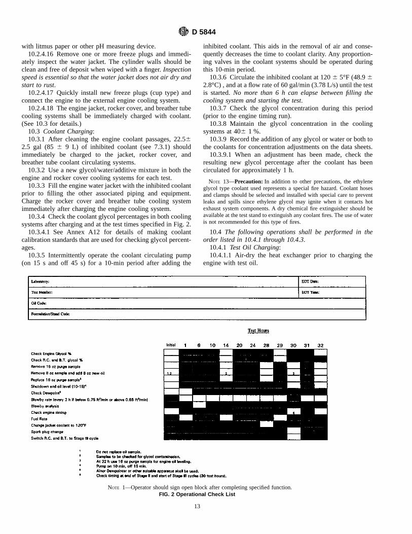
systems after charging and at the test times specified in Fig. 2.10.3.4.1 See Annex A12 for details of making coolant
calibration standards that are used for checking glycol percent-ages.10.3.5 Intermittently operate the coolant circulating pump
(on 15 s and off 45 s) for a 10-min period after adding the
inhibited coolant. This aids in the removal of air and conse-quently decreases the time to coolant clarity. Any proportion-ing valves in the coolant systems should be operated duringthis 10-min period.10.3.6 Circulate the inhibited coolant at 1206 5°F (48.96
2.8°C) , and at a flow rate of 60 gal/min (3.78 L/s) until the testis started.No more than 6 h can elapse between filling thecooling system and starting the test.10.3.7 Check the glycol concentration during this period
(prior to the engine timing run).10.3.8 Maintain the glycol concentration in the cooling
systems at 406 1 %.10.3.9 Record the addition of any glycol or water or both to
the coolants for concentration adjustments on the data sheets.10.3.9.1 When an adjustment has been made, check the
resulting new glycol percentage after the coolant has beencirculated for approximately 1 h.
NOTE 13—Precaution: In addition to other precautions, the ethyleneglycol type coolant used represents a special fire hazard. Coolant hosesand clamps should be selected and installed with special care to preventleaks and spills since ethylene glycol may ignite when it contacts hotexhaust system components. A dry chemical fire extinguisher should beavailable at the test stand to extinguish any coolant fires. The use of wateris not recommended for this type of fires.
10.4 The following operations shall be performed in theorder listed in 10.4.1 through 10.4.3.10.4.1 Test Oil Charging:10.4.1.1 Air-dry the heat exchanger prior to charging the
engine with test oil.
NOTE 1—Operator should sign open block after completing specified function.FIG. 2 Operational Check List
D 5844
13
10.4.1.2 Use a single, clean, well-calibrated and accuratecontainer to install the initial filling of test oil.(a) Add 5 qt, 28 oz (5.56 L) of test oil to the engine through
the oil fill tube.(b) Add 4 oz (118 mL) of test oil to the rocker arm pivots
(approximately 2 oz (59 mL) per side).10.4.2 Installation of Rocker Covers:10.4.2.1 Use special rocker arm covers available from the
CPD.10.4.2.2 Install the rocker covers on the engine after pre-
oiling the rocker arm pivots. (Note that the coolant lines shallhave been installed on the rocker covers prior to coolantcharging.)10.4.3 Timing Run:10.4.3.1 After the engine is filled with oil, start the external
oil pump and start the engine (see 10.5) for a 10-min timingrun. The carburetor intake air horn is not to be connectedduring the timing run.10.4.3.2 Initially, establish the engine speed at 1500 r/min
for 2 min and set the spark timing at 27° before top dead center(btdc).10.4.3.3 For the remainder of the 10 min, operate the engine
at 1500 r/min and 25 bhp (18.6 kW).10.4.3.4 Control the oil sump temperature, and the coolant
temperatures in the jacket, rocker covers, breather tube, andintake manifold crossover at 1206 5°F (48.96 2.8°C)10.4.3.5 Draw the initial oil sample at 10 min after starting,
but prior to stopping the engine (see Fig. 3).10.4.3.6 During the timing run, check that the ignition
voltage is at least 13 V.Be sure that the ignition voltage is atleast 13 V throughout the test.10.4.3.7 At the end of the 10-min timing run, shutdown the
engine (see 10.7.2).10.4.3.8 Re-torque the exhaust manifold bolts after the
timing run.10.4.3.9 Fifteen minutes after the shutdown at the end of the
timing run, switch the rocker covers and breather tube cooling
system to chilled glycol at 60°F (15.6°C). See A4.1.10.5 Engine Startup Procedure—Use the following proce-
dure to start the engine where motor generator dynamometersare not used:10.5.1 Back the idle screw off the lowest cam position.10.5.2 Close throttle completely.10.5.3 Crank engine for no more than 3 s.10.5.4 During cranking, crack throttle at high intake mani-
fold vacuum. This procedure normally provides sufficient fuelfor starting.Do not pour fuel directly into the carburetor orintake manifold.10.5.5 Repeat steps (c) and (d) if engine fails to start.10.5.6 When engine has been started, bring to 1500 r/min
and 25 bhp (18.6 kW) as soon as possible (except for timingrun).10.5.7 After 2 min of operation, set the specified speed and
load conditions.
NOTE 14—Precaution: In addition to other precautions, guards shouldbe installed around all moving parts. When the engine is operating at highspeed, heavy duty guards should be placed on both sides of the engine andpersonnel should be cautioned against working alongside the engine andcoupling shaft. All fuel lines, oil lines and electrical wiring should beproperly routed, guarded, and kept in good condition. Safety masks orglasses should always be worn by personnel working on and around theengine, and no loose or flowing clothing should be worn near a runningengine.The external parts of the engine and the floor area around the engine
should be kept free of oil or fuel spills. Do not allow containers of fuel oroil to accumulate in the testing area.Personnel should be alert for leaking fuel or exhaust gas. Leaking fuel
represents a fire hazard and exhaust gas fumes are noxious.
11. Procedure—During the Test
11.1 Engine Shutdown Procedure:11.1.1 Use the following procedure in stopping the engine:11.1.1.1 Reduce engine speed and load to 1500 r/min and 25
bhp (18.6 kW).11.1.1.2 Disconnect the fuel line or shut off fuel.
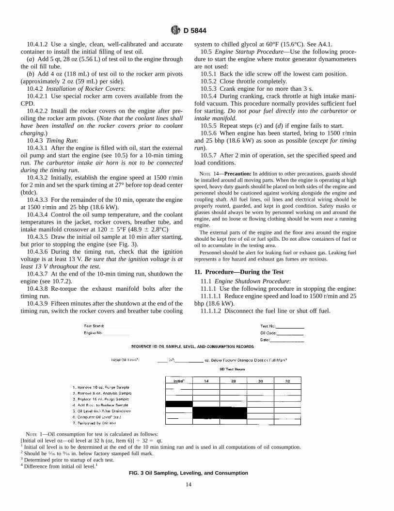
NOTE 1—Oil consumption for test is calculated as follows:[Initial oil level oz—oil level at 32 h (oz, Item 6)]4 325 qt.1 Initial oil level is to be determined at the end of the 10 min timing run and is used in all computations of oil consumption.2 Should be5⁄16 to 9⁄16 in. below factory stamped full mark.3 Determined prior to startup of each test.4 Difference from initial oil level.1
FIG. 3 Oil Sampling, Leveling, and Consumption
D 5844
14

11.1.1.3 Allow the engine to run out of fuel.
NOTE 15—Precaution: In addition to other precautions, the test instal-lation should be equipped with a fuel shut-off valve which is designed toautomatically cut off the fuel supply to the engine when the engine is notrunning. A remote station for cutting off fuel from the test stand isrecommended. Suitable interlocks should be provided so that the engine isautomatically shut down when any of the following events occur: engineor dynamometer loses field current, engine overspeeds, exhaust systemfails, room ventilation fails, or the fire protection system is activated.Consider installing an excessive vibration pickup interlock if the
equipment operates unattended. Fixed fire protection equipment should beprovided.
11.2 Oil Sampling:11.2.1 Take all oil samples with the engine running.11.2.1.1 First, remove a 16-oz (472-mL) purge sample, and
then draw a 8-oz (236-mL) sample from the engine.11.2.1.2 The initial 8-oz (236-mL) oil sample is taken at the
end of the timing run (see section 10.8.5). Take the other oilsamples at 14, 28, 30 and 32 h.11.2.1.3 While the engine is operating, the tapped oil fill
hole is plugged tightly with a3⁄4-in. NPT plug. Alternatively, a3⁄4-in. NPT pipe nipple, 3 to 4-in. long, with a3⁄4-in. to 11⁄4-in.NPT reducing coupling and a 11⁄4-in. NPT pipe plug can beused. This alternative nipple arrangement, which facilitates theaddition of oil, shall be securely tightened.11.2.1.4 After shutting down the engine, return the 16-oz
(472-mL) purge sample to the engine after each sample isremoved, and add 8 oz (236 mL) of new oil (except at theinitial oil sampling, where only the purge sample is returnedand no new oil is added).11.2.1.5 The oil sampling checklist and suggested oil log
format is shown in Fig. 3.11.3 Checking Oil Samples for Glycol Content:11.3.1 Check the initial, 14-h, and 30-h oil samples for
glycol content using Test Method D 2982, Procedure A12.1.11.3.1.1 If the glycol content determination of the initial
sample is positive, check a sample of the new oil using thesame test method.11.3.1.2 If the glycol content determination of the sample of
new oil is similar to that of the initial sample, no additionalanalyses are required and the test should be continued.11.3.1.3 If the initial, 14-h, or 30-h oil samples show a
consistently higher level of glycol than the new oil, then thetest shall be invalidated and the engine completely rebuilt.11.3.1.4 Include all glycol leak check results in the final
report.11.4 Oil Leveling:11.4.1 After the 10-min timing run, at the 30-h shutdown,
and at the end of the test (32 h), shut down the engine for 25min to allow the oil to drain down.11.4.2 During these 25-min shutdowns, conduct the follow-
ing operations:11.4.2.1 Run the external oil circulating pump for the first
10 min and then shut it off for 15 min. This procedure willmaintain the oil sump at the required oil temperature of 12065°F (48.96 2.8°C).11.4.2.2 Maintain the jacket coolant temperature at 1206
5°F (48.96 2.8°C).11.4.2.3 Maintain the rocker cover and breather tube coolant
temperatures at 1206 5°F (48.96 2.8°C), except during thelast 10 min after the timing run when they are reduced to 6062°F (15.66 1.1°C).11.4.2.4 Remove the dipstick guide tube cap (see print
RX-117349-A), which is used during engine operation, andinstall the dipstick (see Annex A13 for the dipstick calibrationprocedure).11.4.2.5 Determine the oil level by dipstick measurement 25
min after engine shutdown. (The oil leveling operationalchecklist is shown as Fig. 2, and the oil leveling log sheet isshown as Fig. 3.)11.4.2.6 Remove the dipstick and reinstall the dipstick guide
tube cap.11.4.3 The initial oil level, which is determined after the
10-min timing run, is used in all computations of oil consump-tion.11.5 Test Periods:11.5.1 The engine test is operated for a total of 32 h under
three sets of conditions; that is, 28 h in Stage I (low speed andcold temperatures), 2 h in Stage II (low speed and slightlywarmer temperatures), and 2 h inStage III (high speed and hottemperatures).11.5.2 Count test time for Stage I and Stage III from the
moment when all the specified test conditions are reached.11.5.3 When changing from Stage I to Stage II, 3 min are
allowed for the temperature change, and the 3 min are countedas test time for Stage II.11.5.4 Between Stages II and III, there is a scheduled 25
min shutdown period that is not counted as test time duringeither stage.11.6 Non-Scheduled Shutdowns—One non-scheduled shut-
down is allowed, for a maximum of 20 min if it occurs duringthe cold cycle and 30 min if it occurs on the hot cycle.11.7 Data Recorded at Hourly Intervals:11.7.1 Engine speed, r/min,11.7.2 Engine load, bhp (kW),11.7.3 Oil temperature (sump), °F (°C),11.7.4 Oil temperature (filter block), °F (°C),11.7.5 Jacket coolant out temperature, °F (°C),11.7.6 Jacket coolant inlet temperature, °F (°C),11.7.7 Jacket coolant flow rate, gal/min (L/s),11.7.8 Rocker covers (both left and right) and breather tube
system coolant outlet temperatures, °F (°C),11.7.9 Rocker covers and breather tube system coolant flow
rates, gal/min (L/s),11.7.10 Rocker cover system coolant outlet pressure, psi
(kPa),11.7.11 Crossover coolant outlet temperature, °F (°C),11.7.12 Crossover coolant flow rate, gal/min (L/s),11.7.13 Crossover coolant outlet pressure, psi (kPa),11.7.14 Ambient air temperature, °F (°C),11.7.15 Fuel temperature, °F (°C),11.7.16 Intake manifold vacuum, in. Hg (kPa),11.7.17 Exhaust back pressure (left and right), in. of water
(kPa),11.7.18 Exhaust back pressure differential, in. of water (Pa),11.7.19 Carburetor air dew point or wet bulb temperature,°
F (°C),
D 5844
15

11.7.20 Carburetor air temperature, °F (°C),11.7.21 Carburetor air pressure, in. of water (Pa),11.7.22 Oil pump outlet pressure, psi (kPa),11.7.23 Engine oil pressure, psi (kPa),11.7.24 Crankcase pressure, in. water (Pa),11.7.25 Breather tube blowby gas outlet temperature,° F
(°C), and11.7.26 Intake manifold mixture temperature, °F (°C).11.8 Data Recorded at Irregular Intervals:11.8.1 Make and record blowby rates, blowby analyses,
glycol percentage checks, and dew point determinations atapproximately the hours shown in Fig. 2.11.8.1.1 Observe and record crankcase pressure readings
prior to blowby determinations.11.8.2 Make and record air-to-fuel ratio measurements at
hours 1, 7, 14, 21, 28, and 30 for the cold cycle and at hours 31and 32 for the hot cycle.11.8.3 Suggested data log sheets are shown in Fig. 4 and
Fig. 5.11.9 Engine Operating Conditions:11.9.1 Following the timing run (10.4.1) and the initial oil
level check, operate the engine continuously for 28 h at theStage I conditions shown in Table 1.11.9.2 Following Stage I (28 h) operation, and without
shutdown, operate the engine for an additional 2 h atStage IIconditions; these are under the same conditions as in Stage I,except for the changes noted in Table 2.11.9.2.1 Make jacket coolant out temperature change from
110 to 120°F (43.3 to 48.9°C) within 3 min. The 3 min arecounted as test time for Stage II.11.9.3 Shut down the engine for 25 min at the end of Stage
II operation (30 h).11.9.3.1 Disconnect the air supply to the carburetor imme-
diately after shutting down the engine.11.9.3.2 Maintain the jacket coolant out temperature at 120
6 5°F (48.96 2.8°C).11.9.3.3 Leave the external oil circulating pumpon for 10
min, and then shutoff for the final 15 min.11.9.3.4 Maintain the oil temperature at 1206 5°F (48.96
2.8°C).11.9.3.5 Determine the oil level by dipstick measurement at
the end of the 25 min shutdown period.11.9.3.6 During this 25-min shutdown:(a) Make the necessary adjustments to the rocker cover and
breather tube cooling circuit for the Stage III (hot) conditions(see Fig. A1.60 [Print No. RX-117928-C]).(b) Install new R46SZ spark plugs.11.9.4 Immediately after the 25-min shutdown period, start
the engine and connect the carburetor air supply. Operate theengine for 2 h under the Stage III high speed-hot temperatureconditions shown in Table 3.11.9.4.1 Count test time from the moment when all of the
conditions in Table 3 are obtained (15 to 30 min are permittedfor stabilization).11.9.5 After the two hours at Stage III conditions (32 h of
engine operation total), reduce speed and load to 1500 r/minand 25 bhp (18.6 kW), respectively, and operate for 2 to 4 minprior to shutdown.
11.9.5.1 Reduce both the jacket coolant and oil sumptemperatures to 1206 5°F (48.96 2.8°C) during the 2 to 4min of operation.
12. Procedure—at the End of the Test
12.1 Shut down the engine and determine the oil level usinga 25-min draindown time (as described in 11.4).12.2 The glycol coolant should be circulated through the
block, rocker covers, and intake manifold exhaust crossover atthe flow rates specified (in Stage I or III) and 1206 5°F (48.96 2.8°C) for 30 min (time starts as soon as the engine isstopped).12.2.1 Immediately drain the glycol mixture following the
30 min of circulation.12.2.2 The external water system should be immediately
flushed until the flush water is clear.12.2.3 Remove the freeze plugs and inspect the water
jacket. Record cleanliness condition.12.3 The breather tube cooling system should be drained
immediately following the inspection of the water jacket.12.4 Flush the external oil cooling system (see A3.2) within
15 min of the determination of the final oil level (see 12.1).
13. Interpretation of Results
13.1 Engine Disassembly and Elapsed Time—General:13.1.1 On completion of the test, completely disassemble
the engine for inspection and rating. A maximum of 2 h isallowed between test completion and removal of parts to berated (time starts as soon as the final oil level is completed).13.1.1.1 Disassemble and immediately clean all parts to be
rated.13.1.1.2 Handle all parts to be rated with gloved hands
during the disassembly process.13.2 Disassembly and Preparation of Parts for Rating:13.2.1 Prior to disassembling the hydraulic valve lifters,
perform the following visual inspection of each lifter:13.2.1.1 Position lifter so that the foot faces downward.13.2.1.2 Use a soft cloth, such as a Teri Towel,40 to remove
any oil from the top surface of the pushrod seat.13.2.1.3 Observe the orientation of the top of the pushrod
seat in relation to the bottom of the lifter body retaining clip.(a) If any portion of the top of the pushrod seat touches any
portion of the retaining clip, rate the plunger as beingfree.(b) Rate the plunger asstuck, if the top of the pushrod seat
does not touch any portion of the retaining clip.13.2.1.4 Report the total number of lifter assemblies rated as
stuckon the test results page of the report.13.2.2 Completely disassemble the hydraulic valve lifters,
and remove the oil pump relief valve and the pushrods. Theseare the parts to be rated and special care is required in handlingthe parts.13.2.2.1 To facilitate the disassembly of lifters, a lifter
plunger remover, such as shown on prints RX-117257-Cthrough RX-117260-A, is recommended.13.2.2.2 After disassembly and prior to rating, clean the
parts listed in 13.2.2 according to the following procedure:
40 Available from local suppliers of Kimberly Clark products.
D 5844
16
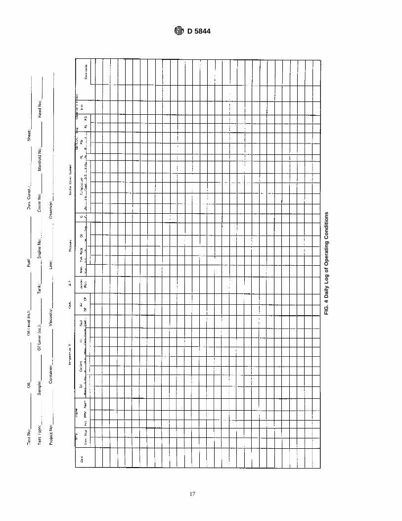
FIG.4DailyLogofOperatingConditions
D 5844
17

(a) Remove the test oil film using an aliphatic naphthawash.(b) Soak the parts in new, clean organic solvent (see 7.2) for
about 10 min to remove hardened organic deposits.(c) Wash the parts a second time using new, clean, aliphatic
naphtha.(d) Wipe each part using a Teri Towel; be sure that all
solvent film is removed from the rating surfaces prior to rating.13.2.2.3 Immediately after the test parts are cleaned, either
rate the parts or store them in a desiccator (be sure that thedesiccant is in satisfactory condition) until time of rating.13.3 Rust Rating:13.3.1 Environment—Use a lamp with two 15 Wcool white
fluorescent bulbs41 which produce 350 to 500 candlepoweragainst a white background rating area.13.3.2 Parts Layout—A rust rating board similar to that
shown in print RX-117552-D is recommended.13.3.3Method:13.3.3.1 Rate all valve lifter bodies, plungers and balls,
pushrods and the relief valve for rust or corrosion deposits, orboth, using the methods detailed in CRC Manual No. 7.(a) In Manual No. 7, the protective plastic covers are
standards themselves and these shall be periodically inspected
41Available from Dazor Manufacturing Corp., 4455 DuncanAve., St. Louis, MO63110.
FIG. 5 Supplemental Daily Log
D 5844
18
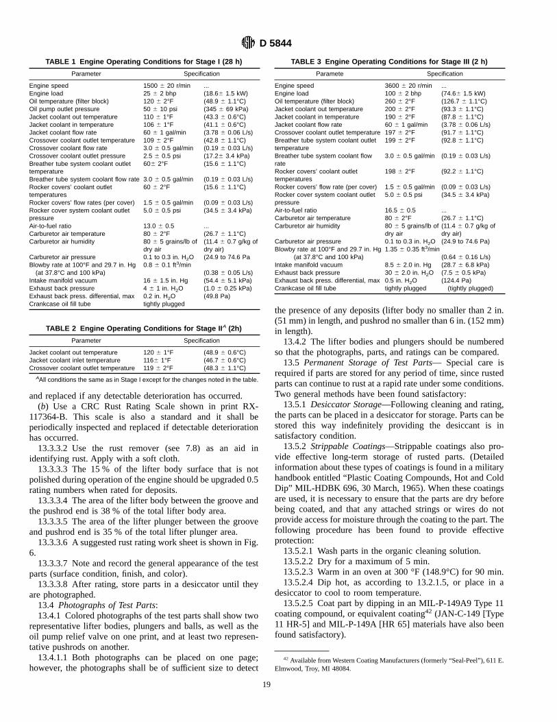
and replaced if any detectable deterioration has occurred.(b) Use a CRC Rust Rating Scale shown in print RX-
117364-B. This scale is also a standard and it shall beperiodically inspected and replaced if detectable deteriorationhas occurred.13.3.3.2 Use the rust remover (see 7.8) as an aid in
identifying rust. Apply with a soft cloth.13.3.3.3 The 15 % of the lifter body surface that is not
polished during operation of the engine should be upgraded 0.5rating numbers when rated for deposits.13.3.3.4 The area of the lifter body between the groove and
the pushrod end is 38 % of the total lifter body area.13.3.3.5 The area of the lifter plunger between the groove
and pushrod end is 35 % of the total lifter plunger area.13.3.3.6 A suggested rust rating work sheet is shown in Fig.
6.13.3.3.7 Note and record the general appearance of the test
parts (surface condition, finish, and color).13.3.3.8 After rating, store parts in a desiccator until they
are photographed.13.4 Photographs of Test Parts:13.4.1 Colored photographs of the test parts shall show two
representative lifter bodies, plungers and balls, as well as theoil pump relief valve on one print, and at least two represen-tative pushrods on another.13.4.1.1 Both photographs can be placed on one page;
however, the photographs shall be of sufficient size to detect
the presence of any deposits (lifter body no smaller than 2 in.(51 mm) in length, and pushrod no smaller than 6 in. (152 mm)in length).13.4.2 The lifter bodies and plungers should be numbered
so that the photographs, parts, and ratings can be compared.13.5 Permanent Storage of Test Parts— Special care is
required if parts are stored for any period of time, since rustedparts can continue to rust at a rapid rate under some conditions.Two general methods have been found satisfactory:13.5.1 Desiccator Storage—Following cleaning and rating,
the parts can be placed in a desiccator for storage. Parts can bestored this way indefinitely providing the desiccant is insatisfactory condition.13.5.2 Strippable Coatings—Strippable coatings also pro-
vide effective long-term storage of rusted parts. (Detailedinformation about these types of coatings is found in a militaryhandbook entitled “Plastic Coating Compounds, Hot and ColdDip” MIL-HDBK 696, 30 March, 1965). When these coatingsare used, it is necessary to ensure that the parts are dry beforebeing coated, and that any attached strings or wires do notprovide access for moisture through the coating to the part. Thefollowing procedure has been found to provide effectiveprotection:13.5.2.1 Wash parts in the organic cleaning solution.13.5.2.2 Dry for a maximum of 5 min.13.5.2.3 Warm in an oven at 300 °F (148.9°C) for 90 min.13.5.2.4 Dip hot, as according to 13.2.1.5, or place in a
desiccator to cool to room temperature.13.5.2.5 Coat part by dipping in an MIL-P-149A9 Type 11
coating compound, or equivalent coating42 (JAN-C-149 [Type11 HR-5] and MIL-P-149A [HR 65] materials have also beenfound satisfactory).
42 Available fromWestern Coating Manufacturers (formerly “Seal-Peel”), 611 E.Elmwood, Troy, MI 48084.
TABLE 1 Engine Operating Conditions for Stage I (28 h)
Parameter Specification
Engine speed 1500 6 20 r/min ...Engine load 25 6 2 bhp (18.66 1.5 kW)Oil temperature (filter block) 120 6 2°F (48.9 6 1.1°C)Oil pump outlet pressure 50 6 10 psi (345 6 69 kPa)Jacket coolant out temperature 110 6 1°F (43.3 6 0.6°C)Jacket coolant in temperature 106 6 1°F (41.1 6 0.6°C)Jacket coolant flow rate 60 6 1 gal/min (3.78 6 0.06 L/s)Crossover coolant outlet temperature 109 6 2°F (42.8 6 1.1°C)Crossover coolant flow rate 3.0 6 0.5 gal/min (0.19 6 0.03 L/s)Crossover coolant outlet pressure 2.5 6 0.5 psi (17.26 3.4 kPa)Breather tube system coolant outlettemperature
606 2°F (15.6 6 1.1°C)
Breather tube system coolant flow rate 3.0 6 0.5 gal/min (0.19 6 0.03 L/s)Rocker covers’ coolant outlettemperatures
60 6 2°F (15.6 6 1.1°C)
Rocker covers’ flow rates (per cover) 1.5 6 0.5 gal/min (0.09 6 0.03 L/s)Rocker cover system coolant outletpressure
5.0 6 0.5 psi (34.5 6 3.4 kPa)
Air-to-fuel ratio 13.0 6 0.5 ...Carburetor air temperature 80 6 2°F (26.7 6 1.1°C)Carburetor air humidity 80 6 5 grains/lb of
dry air(11.4 6 0.7 g/kg ofdry air)
Carburetor air pressure 0.1 to 0.3 in. H2O (24.9 to 74.6 PaBlowby rate at 100°F and 29.7 in. Hg 0.8 6 0.1 ft3/min(at 37.8°C and 100 kPa) (0.38 6 0.05 L/s)
Intake manifold vacuum 16 6 1.5 in. Hg (54.4 6 5.1 kPa)Exhaust back pressure 4 6 1 in. H2O (1.0 6 0.25 kPa)Exhaust back press. differential, max 0.2 in. H2O (49.8 Pa)Crankcase oil fill tube tightly plugged
TABLE 2 Engine Operating Conditions for Stage II A (2h)
Parameter Specification
Jacket coolant out temperature 120 6 1°F (48.9 6 0.6°C)Jacket coolant inlet temperature 1166 1°F (46.7 6 0.6°C)Crossover coolant outlet temperature 119 6 2°F (48.3 6 1.1°C)
AAll conditions the same as in Stage I except for the changes noted in the table.
TABLE 3 Engine Operating Conditions for Stage III (2 h)
Paramete Specification
Engine speed 3600 6 20 r/min ...Engine load 100 6 2 bhp (74.66 1.5 kW)Oil temperature (filter block) 260 6 2°F (126.7 6 1.1°C)Jacket coolant out temperature 200 6 2°F (93.3 6 1.1°C)Jacket coolant in temperature 190 6 2°F (87.8 6 1.1°C)Jacket coolant flow rate 60 6 1 gal/min (3.78 6 0.06 L/s)Crossover coolant outlet temperature 197 6 2°F (91.7 6 1.1°C)Breather tube system coolant outlettemperature
199 6 2°F (92.8 6 1.1°C)
Breather tube system coolant flowrate
3.0 6 0.5 gal/min (0.19 6 0.03 L/s)
Rocker covers’ coolant outlettemperatures
198 6 2°F (92.2 6 1.1°C)
Rocker covers’ flow rate (per cover) 1.5 6 0.5 gal/min (0.09 6 0.03 L/s)Rocker cover system coolant outletpressure
5.0 6 0.5 psi (34.5 6 3.4 kPa)
Air-to-fuel ratio 16.5 6 0.5 ...Carburetor air temperature 80 6 2°F (26.7 6 1.1°C)Carburetor air humidity 80 6 5 grains/lb of
dry air(11.4 6 0.7 g/kg ofdry air)
Carburetor air pressure 0.1 to 0.3 in. H2O (24.9 to 74.6 Pa)Blowby rate at 100°F and 29.7 in. Hg 1.35 6 0.35 ft3/min
(at 37.8°C and 100 kPa) (0.64 6 0.16 L/s)Intake manifold vacuum 8.5 6 2.0 in. Hg (28.7 6 6.8 kPa)Exhaust back pressure 30 6 2.0 in. H2O (7.5 6 0.5 kPa)Exhaust back press. differential, max 0.5 in. H2O (124.4 Pa)Crankcase oil fill tube tightly plugged (tightly plugged)
D 5844
19
14. Report
14.1 Report the Following Information:14.1.1 Test oil results (Annex A16),14.1.2 Reference oil results,14.1.3 Operational summary,14.1.3.1 For additional operational details, see Fig. A16.7.14.1.3.2 All specified values are judged and reported by the
Absolute Method.14.1.4 Test validity confirmation (Fig. A16.7),14.1.5 Reference oil test telefax to the TMC,14.1.6 Hardware identification, and14.1.7 Operational deviations (Fig. A16.6).14.2 Calculation of Rust Results—Report rust results to two
significant places, using the method described in Practice E 29.Use the RatingWorksheet. The engine rust rating is the averageof the five parts listed in 14.2.1 to 14.2.5.14.2.1 Valve lifter bodies,14.2.2 Valve lifter plungers,14.2.3 Valve lifter balls,14.2.4 Oil pump relief valve, and14.2.5 Pushrods.14.3 Lifter Plunger Sticking—Report the number of lifter
plungersstuck(see 13.2 for the definition of astucklifter).14.4 Oil Pump Relief Valve Sticking— If the oil pump relief
valve sticks, excessive oil pressure generally is observedduring Stage III and should be noted.14.5 Oil Consumption Computation—Compute oil con-
sumption as total oil charged to the engine less samples anddiscards drained. Maximum oil consumption allowed is 24 ozor 0.75 qt (708 mL).14.6 Operational Deviations:14.6.1 A number of operational parameters are not included
in the summary sheet. Some examples are glycol coolantconcentrations, warm-up times, unscheduled shutdowns, shut-down procedures, and oil level information.14.6.2 Reportall observed deviations from the specified
limits (not only hourly readings but also during the hour) byrecording these on the daily log sheet and on a supplementalreport page.14.6.2.1 Report the test hour, magnitude, and duration of the
deviation for both these special, as well as the normallysummarized, parameters.14.6.3 Report, on a supplemental report page, if no operat-
ing deviations occurred.14.7 Additional Operational Details:14.7.1 Record maximum, minimum, and average crankcase
pressures on the summary sheet. Use the value of 4.98 forcalculating crankcase pressure average when pressuresare +4.98 kPa.14.7.2 In the event of any oil pressure deviation from
prescribed limits, include a plot of oil pressure versus testhours in the test report.14.7.3 Include plots of blowby rate and crankcase pressure
versus test hours in the test report. The maximum scale valuefor the plot of crankcase pressure should be 1 in. of water(unless higher values are recorded). Use Practice E 29 forrounding off data.
15. Precision and Bias
15.1 Precision:15.1.1 Non-reference Oils—To aid the potential user of this
test method to assess the variability that can be expectedbetween test results when the test method is used in one ormore reasonably competent laboratories, the precision infor-mation in Table 4 has been developed.15.1.1.1 The non-reference oil precision for this test method
is determined by the statistical analysis of sets of datasubmitted by users of the test method. Each set of data consistsof two or more engine test results, on the same oil formulation.Each data set can be from tests run in the same laboratory ordifferent laboratories, and with any approved fuel batch. Thedata are collected and analyzed by industry volunteers workingwithin the Sequence IID Test Method Surveillance Panel, andare reported semiannually to the ASTM D02.B0 Subcommit-tee.15.1.1.2 The statistical criteria summarized in Table 4
represent the estimate of reproducibility, based on 24 sets ofdata and 51 total tests. These data were obtained over theperiod of October 1, 1993 through March 31, 1994. (If apotential user has a desire to know what the most recentprecision data are for non-reference oils, the TMC can providethe information by consulting the appropriate SurveillancePanel report.)15.1.1.3Reproducibility (R)—The difference between two
single and independent results obtained on the same oil bydifferent operators working in different laboratories and would,in the long run, in the normal and correct conduct of the testmethod, exceed the values in Table 4 in only one case intwenty.15.1.1.4 No similar estimate of non-reference oil repeatabil-
ity is available with this test method, since the number ofnon-reference oil tests repeated in the same engine, test stand,and laboratory by the same operator are essentially non-existent.15.1.1.5 An estimate of reference oil repeatability and
reproducibility is contained in the reference oil data basemaintained by the TMC. Reference oil precision data for theperiod January 1, 1992 through June 30, 1994 are shown inTable 5. The repeatability precision data were based on 97degrees of freedom, and the reproducibility precision data werebased on 101 degrees of freedom. Updated reference oilprecision data are available upon request from the TMC.15.1.2 Bias—Bias is determined by applying an accepted
statistical technique to reference oil test results and when asignificant bias is determined, a severity adjustment is permit-ted for non-reference oil test results (see Annex A14).
16. Keywords
16.1 engine oil; engine oil testing; engine rusting; SequenceIID
TABLE 4 Test Precision—Non-reference Oils
Parameter Standard Deviation Reproducibility, RAverage engine rust 0.22 0.62
D 5844
20

ANNEXES
(Mandatory Information)
A1. ENGINE TEST STAND CALIBRATION
A1.1 Standard Sequence IID tests shall be conducted onlyin calibrated engine test stands.
A1.1.1 Engine test stand calibration is accomplished by alaboratory conducting the Sequence IID test method withreference oils furnished by the ASTM Test Monitoring Center(TMC) and stored at the laboratory.A1.1.1.1 The laboratory has responsibility to keep the
on-site blind reference oil inventory at or above the minimumlevel specified by the TMC.A1.1.2 These reference oils are normally supplied under
code numbers (blind reference oils) to ensure that the testinglaboratory will not be influenced by preconceived opinions inassessing the test results.A1.1.3 It is the test laboratory’s responsibility to maintain
calibration of its test stands in accordance with the guidelinesfurnished by the TMC.A1.1.3.1 When laboratory personnel decide that a reference
oil test should be run, they request a blind oil code from theTMC.A1.1.3.2 Upon completion of the blind reference oil test, a
summary of the data is sent to the TMC by telephone facsimiletransmission, or some other method acceptable to the TMC.A1.1.3.3 The TMC will review the data and contact the
laboratory to report the laboratory’s calibration status.A1.1.3.4 All reference oil tests, whether aborted, invali-
dated, or successfully completed shall be reported to the TMC.A1.1.4 No more than 18 test starts nor 90 days shall elapse
on a calibrated stand without running an acceptable blindreference oil test.A1.1.5 To ensure that a laboratory’s test severity stays
within acceptable guidelines, no more than 36 total test startsare allowed, on all of the calibrated stands in a laboratory,between reference oil tests in the laboratory.A1.1.6 The TMC may schedule more frequent or less
frequent reference oil tests, at its discretion, depending onspecial circumstances.A1.1.6.1 Non-reference oil tests conducted during a special
extended period between reference oil tests shall be annotatedin the test note section of the report.A1.1.7 Failure of a reference oil test to meet the established
statistical guidelines (the TMC can provide details), can beindicative of a false alarm, test stand, testing laboratory, orindustry-related problem.A1.1.7.1 The TMC has the ultimate responsibility for de-
ciding whether an unacceptable blind reference oil test isisolated to one particular stand or related to other stands. TheTMC will seek industry expertise, as necessary, to help inmaking this decision.A1.1.7.2 If the problem is determined to be a false alarm or
involving only one test stand, there is no impact on non-reference oil tests running in other test stands within thelaboratory.A1.1.7.3 If it is determined that the problem is laboratory-
related, non-reference oil tests during the problem period shallbe considered nonstandard tests, unless there is specific evi-dence to the contrary for each individual test.A1.1.7.4 The laboratory, in conjunction with the TMC, shall
attempt to determine the problem source.A1.1.7.5 Until the problem is identified, corrected and an
acceptable reference oil test completed in the involved stand,or one of the involved stands (when the problem is related toother stands), standard testing of non-reference oils cannot beconducted in the stand(s) in question.A1.1.7.6 Industry problems shall be resolved by the Se-
quence IID Test Method Surveillance Panel that reports toSubcommittee B in ASTM Committee D-2, Petroleum Prod-ucts and Lubricants.A1.1.8 If a nonstandard test is conducted on a calibrated test
stand, the test stand has to be recalibrated prior to againrunning standard tests.
A1.2 Each test shall be numbered to identify the test (IID),the stand number, the stand test number (0 to 18), and asequential laboratory test number based on the starting date ofthe test.
A1.2.1 For example, IID 58-0-401 defines a test on stand 58as a reference test which is numbered as the 401st IID test inthe laboratory.A1.2.1.1 The only exception to this format is that the
sequential laboratory test number shall be followed by theletter A for the first rerun, B for the second rerun, and so forth,of invalid or unacceptable reference oil tests.
A1.3 Each laboratory that is monitored by the TMC shallrun at least one donated test per year on a poor reference oilsupplied through the normal blind reference oil system.
A1.3.1 The purpose of such tests is to verify that eachlaboratory discriminatesgoodoils from poor oils.
TABLE 5 Test Precision—Reference Oils
ParameterRepeatability Reproducibilitysr r sR R
Average engine rust 0.115 0.323 0.116 0.325
D 5844
21

A2. EXTERNAL ENGINE COOLING SYSTEM
A2.1 An external cooling system such as shown on printRX-116681-D is required to maintain the specified jacketcooling temperature during the operating and shutdown por-tions of the test. The system has the following features:
A2.1.1 It shall not be pressurized.A2.1.2 The pumping system shall be capable of delivering
60 6 1 gal/min (3.79 L/s).A2.1.3 It shall have a total capacity of 22.56 2.5 gal (856
9 L).
A2.1.4 A sharp-edge orifice meter33 such as shown on printsRX-116645-D through RX-116650-D shall be used for themeasurement of coolant flow rates.
A2.1.5 A system to control the coolant flow rate such asshown on print RX-117161-C is required.
A2.1.6 The system shall have provisions (for example, lowpoint drains) for draining all of the flushing water prior toinstalling a new glycol mixture.
A3. EXTERNAL JACKETED ROCKER COVER, INTAKE MANIFOLD CROSSOVER AND BREATHER TUBE COOLINGSYSTEMS
A3.1 Description of the System
A3.1.1 An external cooling system for the rocker covers,intake manifold exhaust crossover, and breather tube, incorpo-rating pumps, flowmeters, plumbing connections, and heatexchangers, such as shown on prints RX-117731-C and RX-117814-C or RX-117815-C, is required to maintain the speci-fied operating temperatures in these engine parts.A3.1.2 The system shall have the following features:A3.1.2.1 A pump and flowmeter capable of supplying en-
gine coolant to the rocker covers and intake manifold crossoverat 36 1 gal/min (0.196 0.06 L/s); that is, 1.56 0.5 gal/min(0.096 0.06 L/s) per each rocker cover.A3.1.2.2 Maintain the rocker cover coolant outlet pressure
at 5.06 0.5 psi (34.56 3.4 kPa).A3.1.2.3 Maintain the intake manifold exhaust crossover
coolant outlet pressure at 2.56 0.5 psi (17.26 3.4 kPa).A3.1.2.4 Use a second coolant system, having a pump and
flowmeter capable of supplying coolant at 60°F (15.5°C) and 3gal/min (0.19 L/s), to control the temperature of the rocker armand breather tube assembly. This system can be drained uponcompletion of test.A3.1.3 Equip the system with low point drains to allow for
removal of all coolant.
A3.2 Cleaning the System’s Jacketed Rocker Cover
A3.2.1 Either with new rocker covers or after each test,flush the stainless steel rocker covers (see print RX-117470-D)clean with aliphatic naphtha in order to ensure proper heattransfer rates.A3.2.2 Polish the engine side of the rocker covers lightly
with 400 grit 3M cloth (3M Elek-tro Cut Cloth 400J43), orequivalent, before each test.A3.2.3 Clean the coolant side of the rocker covers after
every tenth test, or sooner if a film is present, with concentratednitric acid.
A3.2.3.1 A 1-min exposure to the nitric acid followed bythorough rinsing with water is satisfactory.A3.2.4 Pressure check the rocker covers for leaks at a
pressure of 10 psig (69 kPa) after cleaning.Pressures in excessof 10 psig (69 kPa) are likely to balloon the covers.
A3.3 Cleaning the System’s Breather Tube
A3.3.1 Remove the stainless steel breather tube (see printRX-117729-C) immediately after each test and soak in Oakite811.A3.3.2 After soaking, clean the inside of the tube with
Oakite 811 and a non-cuprous brush (a 0.25 caliber riflecleaning rod with a non-cuprous brush has been found satis-factory).A3.3.3 Following the cleaning procedures described above,
rinse the breather tube with clean aliphatic naphtha.A3.3.4 Breather tube heat exchanger gaskets can be readily
made, or ordered as American Standard Part 2G-3A, 901.44
A3.3.5 Clean the coolant side of the breather tube afterevery tenth test, or sooner if a film is present, with concentratednitric acid.A3.3.5.1 A 1-min exposure to the nitric acid followed by
thorough rinsing with water is satisfactory.A3.3.6 Flush the glycol side of the breather tube with
aliphatic naphtha after each test.A3.3.6.1 Pressure check the glycol side of the breather tube
for leaks after cleaning at a pressure of 10 psig (69 kPa).
A3.4 Cleaning the System’s Intake Manifold
A3.4.1 Wire brush the side exposed to the lifter valley andthoroughly wash with Oakite 811. Follow by rinsing withaliphatic naphtha.A3.4.2 Minimize the exposure of the exhaust crossover
passage to the Oakite 811 cleaning agent.
43 Available through local suppliers. Order 400 grit 3H cloth or 3M Elek-tro-CutCloth 400J, or equivalent.
44 Available from American Standard, Industrial Products Division, P.O. Box 76,Dearborn, MI 48121.
D 5844
22

A4. EXTERNAL OIL COOLING SYSTEM, CLEANING AND CALIBRATION
A4.1 Oil Cooling System
A4.1.1 An external oil cooling system such as shown onprint RX-116680-C is required to maintain the specified oiltemperatures.A4.1.1.1 A positive displacement pump, Viking Oil Pump,
Model 412545 is mandatory. This pump delivers 5.756 0.25gal/min (0.3636 0.016 L/s) at 1150 r/min.A4.1.1.2 There is no relief valve in the system.A4.1.1.3 A heat exchanger assembly, Part BX-250-1,12 is
mandatory. This cooler has a capacity of 1 pt (473 mL).A4.1.2 Pillow blocks should be used to support the drive
shaft and ensure longer pump life.A4.1.3 Suitable fittings, as shown on print RX-118305-D,
shall be provided in the engine oil pan to accommodate the oillines.Do not use cuprous lines or fittings in the cooling system.Do not use magnetic plugs anywhere in the engine or in thecooling system.A4.1.4 The length of the oil lines to the heat exchanger and
valves should be minimized. The total oil volume in theexternal oil cooling system, including the volume of the lines,heat exchanger, valves, pump, and sensing elements shall be 326 2 oz (9466 59 mL) of oil.A4.1.5 Number 8 Aeroquip hose, inside diameter 0.417 in.
(10.59 mm), type T Teflon 280733 and fittings are recom-mended.A4.1.6 If quick disconnect type fittings are used, only the
straight-through type, such as shown on print RX-116680-C,shall be used.
A4.2 Cleaning the Oil Cooling System
A4.2.1 Either with a new cooling system or within 15 minof completing the final oil level in this test method, flush theexternal oil cooling system, including lines, pump, heat ex-changer, and valve with a 100 % by volume solution of Oakite811 until clean.A4.2.2 Periodically, the heat exchanger should be removed
and cleaned separately as discussed in the following:A4.2.2.1 Details of an oil heat exchanger flushing apparatus
are shown in print RX-117374-R.A4.2.2.2 Use Section A of unit for flushing water side of the
heat exchanger, and Section B for flushing the oil side of theexchanger.Do not flush more than two exchangers at one time.(a) Flush the water side of the exchanger for1⁄2 h, using
oxalicacid proportionate concentration. Preheat the solution to1406 5°F (606 2.8°C) and pump at approximately 4 gal/min(0.25 L/s).(b) After 1⁄2 h flush on the water side of the exchanger, rinse
(one pass) with water preheated to 120°F (48.9°C). Do thisuntil the rinse water has a neutral pH.(c) Flush the oil side of the exchanger for1⁄2 h, using 100 %
Oakite 811. Preheat the cleaning agent to 1406 5°F (606
2.8°C) and pump at approximately 2.5 gal/min (0.16 L/s).(d) After 1⁄2 h flush on the oil side of the exchanger, rinse
with Solvasol No. 5 (one pass) until solvent is clear; and then,air dry.(e) Both sides of the exchanger can be flushed at the same
time.A4.2.2.3 After a cleaned heat exchanger has been installed
in the external oil cooling system, flush clean the pump, lines,exchanger, and proportioning valve using aliphatic naphthawith a 300 to 400°F (149 to 204°C) boiling point, and air drythe system before each test.(a) Rotate the external oil pump shaft by hand while air
blowing to ensure that all solvent is removed from the system.
A4.3 Calibrating the External Oil Cooling System FlowRate
A4.3.1 Perform the following procedure to verify that theexternal oil system flow rate meets the specification beforeeach reference oil test and after any system component (forexample, pump, control valve, heat exchanger) is replaced:A4.3.1.1 After cleaning (see Annex A5.2), connect the oil
lines to a calibration oil pan firmly mounted at engine height.A4.3.1.2 Insert a calibrated flow meter in the oil return line.
Use a flow meter with minimum pressure drop and restrictionto flow (a suitable flow meter is the Cox Model AN10 TurbineMeter).(a) Calibrate the flow meter using EF 411 oil heated to 85°F
(29.4°C).(b) Observe typical 10 times diameter straight pipe rule
before and after meter to reduce flow disturbance.A4.3.1.3 Add 5680 mL of EF 411 to oil pan.A4.3.1.4 Operate the oil pump while cycling the 3-way
control valve to purge air from the system (excessive air in theoil will cause erroneous flow measurement, particularly withturbine meters).A4.3.1.5 With the 3-way control valve set at 50 %, record
flow rate when the reading has stabilized and the oil tempera-ture measures 84 to 85°F (28.9 to 30.0°C) by the sumpthermocouple.A4.3.1.6 Determine if the system meets the specified flow
rate of 5.756 0.25 gal/min (21.86 0.95 L/min).(a) If the flow rate doesn’t meet the specification, adjust the
pump clearance or replace the pump, then recheck the flow rateusing the above procedure.
A4.4 Calibrating the Volume of the Oil Cooling System
A4.4.1 Perform the following procedure to verify that theexternal oil cooling system volume meets the specificationbefore every reference oil test, and after any system component(for example, line length, pump, valve) is changed.A4.4.1.1 After cleaning (see Annex A5.2), connect the oil
lines to a calibrated oil pan firmly mounted at engine height.(a) Install a 0.375-in. (9.5-mm) diameter drain valve in
place of the oil drain plug or at the lowest point of the pan.(b) Plug the pan outlet fitting with a rubber stopper, or
modify the outlet by threading with a1⁄2-in. NPT thread so that
45 Available from local Viking distributors, or Viking Pump Division, HoudailleIndustries, Inc., George and Wyeth Sts., Cedar Falls, IA 50613. Alternatively, aViking Model G4125 pump, 0.386 0.03 L/s (66 0.5 gpm) at 1150 rpm and norelief valve, is satisfactory.
D 5844
23

a 1⁄2-in. NPT plug can be screwed in.A4.4.2 Weigh, at room temperature, 5680 mL of solvent
(aliphatic naphtha) with a boiling point greater than 300 °F(149°C) to determine the weight per volume of solvent (g/mL).A4.4.3 Carefully add the weighed solvent to the oil pan.A4.4.4 Operate the oil pump alternately 1 min on and 1 min
off while cycling the 3-way control valve.A4.4.4.1 Repeat cycling of the pump several times to purge
all air from the system.A4.4.5 Turn off the oil pump, and firmly insert rubber
stopper or screw in a1⁄2-in. NPT plug in the pan outlet fittingto keep oil lines filled with solvent when the pan is drained.A4.4.6 Drain solvent remaining in the pan using the pan
drain valve. Manually scrape any residual solvent into the drainusing a plastic scraper.
A4.4.7 Measure the weight of the removed solvent andsubtract from the initial solvent weight.
A4.4.8 Repeat the above process until the weight measure-ment repeats within 4 % (equivalent to 1 fluid oz (30 mL)volume of solvent).
A4.4.9 Determine if the external oil system meets thevolume specification of 256 2 fluid oz (7396 59 mL).
(a) If the measured volume doesn’t meet the specification,adjust the length of the oil lines or fitting size to obtain therequired volume. Recheck the system volume using the aboveprocedure.Note that the system flow rate shall be recheckedwhen any component, except the oil heat exchanger or oil heatexchanger core, is replaced.
A5. EXTERNAL FLUSHING TANK
A5.1 A flushing tank, such as shown on prints RX-116924-C, RX-117230-E and RX-117231-C, is required topremix and circulate the cleaning agents.
A6. EXTERNAL COOLANT MIXING TANK
A6.1 A mixing tank such as shown on print RX-117350-Dcan be used to premix the glycol/water coolant.
A7. EXTERNAL FUEL SYSTEM
A7.1 A suitable pressurized fuel system is required toprovide 2 to 6 psi (14 to 42 kPa) fuel pressure at the carburetor.
A7.2 A Fisher Governor Company regulator46 (Part No.95L-34) has been found satisfactory for controlling the fuelpressure.
A7.3 Additional shutoff valves should be incorporated inthe system so that no fuel pressure is present at the carburetorduring engine shutdowns.
A7.3.1 A suitable shutoff valve is available from SkinnerPrecision Industries47 (Part No. XSD30280).
A8. ENGINE COOLANT PREPARATION
A8.1 Measure the appropriate amount of additive, propor-tionate to the total coolant volume mixed, into a cleancontainer prior to coolant mixing.
A8.2 Premix the glycol and water combination and theadditive concentrate in a container (see Annex A7) prior toadding the finished coolant to the engine, rocker cover, andbreathing tube cooling systems.
A8.3 Approximately 25.1 gal (95 L) of coolant should beprepared. The specified quantity to be charged to the variouscooling systems is 22.56 2.5 gal (856 9 L). See 7.3.1 for thepercentages of glycol and water required.
A8.4 The premixing should not be done more than 2 h priorto filling these systems.
A8.5 Do not heat the coolant during the premixing step.
A8.6 Prior to adding the additive concentrate to the glycoland water mixture, withdraw a small portion of the glycol andwater mix to use as a rinsing agent for the container that holdsthe additive concentrate.
A8.6.1 Add the concentrate and thoroughly rinse the con-tainer.
46 Available from Fisher Governor Co., 1900 Fisher Building, Marshalltown, IA50158.
47 Skinner Electric Valve Division, Skinner Precision Industries, Inc., 100Edgewood Ave., New Britain, CT 06050.
D 5844
24

A9. SEALING COMPOUND APPLICATIONS
A9.1 Adequate amounts of sealing compound, PerfectCircle No. 4 Sealing Compound, should be used on
A9.1.1 Both sides of the head gaskets,A9.1.2 Both sides of each rocker cover spacer-to-head
gasket,A9.1.3 The intake manifold gasket areas adjacent to the
intake ports, andA9.1.4 The front and rear oil pan seals.
A9.2 It is convenient to apply the Perfect Seal compound tothe head gaskets with a small mohair paint roller (17⁄8 in.outside diameter and 3 in. wide (48 mm outside diameter and76 mm wide)).
A9.3 The Perfect Seal compound being used from the 1 gal(4 L) container and the roller can be stored in a small desiccatorsuch as Sargent-Welch No. S-25140..48
A9.4 Either ethyl alcohol (minimum 180 proof) or com-mercially pure isopropyl alcohol can be used as a solent inremoving the Perfect Seal compound from metal surfaces.
A9.5 No. 2 non-hardening Permatex should be applied:
A9.5.1 To the ends of the intake manifold gasket adjacent towater ports and at the exhaust crossover ports.A9.5.2 To the tapered ends of the front and rear elastomeric
intake manifold seals which are adjacent to the cylinder heads,andA9.5.3 On the mating surfaces of the rear main oil seal.
A9.6 Use 3M Super Weatherstrip Adhesive to cement thecork rocker over gasket to the rocker cover spacer.
A9.6.1 Use no compound on the rocker cover side of thecork gasket.
A9.7 The use of anti-seizure compound, such as Fel-ProC-100 or E/M Lubricants, Inc. CP-29 spray or can is recom-mended on the exhaust manifold and pipe bolts.
A10. FASTENER TORQUE SPECIFICATIONS AND TORQUING PROCEDURES
A10.1 Cylinder Head Bolts:
A10.1.1 Install cylinder heads using thoroughly cleanedbolts oiled with EF-411.A10.1.2 After the bolts are finger-tight, torque them in the
sequence shown in the 1977 Oldsmobile Service Manual (Fig.6A3-29).A10.1.3 Torque the bolts three times:(a) First, torque them at 100 lbf·ft (136 N·m),(b) Second, torque them at 110 lbf·ft (139 N·m), and(c) Third, repeat torquing at 110 lbf·ft (139 N·m).
A10.2 Intake Manifold Bolts:
A10.2.1 Install intake manifolds using thorougly cleanedbolts oiled with EF-411.A10.2.2 After the bolts are finger-tight, torque them in the
sequence shown in the 1977 Oldsmobile Service Manual (Fig.6A3-15).A10.2.3 Torque the bolts four times:A10.2.3.1 First, torque them at 15 lbf·ft (20 N·m),
A10.2.3.2 Second, torque them at 35 lbf·ft (47 N·m),A10.2.3.3 Third and fourth, repeat the 35 lbf·ft (47 N·m)
torquing.
A10.3 Other Torque Specifications Are Presented in theFollowing Text Table:
Part lbf·ft (N·m)Bolts for main bearing caps Nos. 1, 2, 3 and 4 80 (108)Bolts for main bearing cap No. 5 100 (136)Flywheel bolts 70 (95)Connecting rod nuts 42 (57)Timing gear-to-camshaft bolt 65 (88)Front cover-to-block bolt (3⁄8in.) 35 (47)Front cover-to-block bolt (5⁄16in.) 25 (34)Crankshaft balance bolt 160 (217)Rocker arm pivot bolts 25 (34)Rocker arm cover bolts 7 (9)Condenser-to-front cover bolts 25 (34)Oil pump-to-bearing cap bolts 35 (47)Oil pan bolts 10 (14)Choke stove plate bolts 15 (20)Water outlet adapter bolts 20 (27)Carburetor-to-intake manifold bolts 10 (14)
A11. ENGINE TEST PARTS
A11.1 Engine Test Parts Classification
A11.1.1 Critical Parts —These are engine parts that areknown to affect test severity. They will be identified with aserial number or a batch lot control number as supplied by theCentral Parts Distributor.12 In the following listing of engineparts (Table A11.1), those in this category will have the lettersCP noted after the description of the part.
A11.1.2 Non-production Parts—These are engine parts nolonger available except through the Central Parts Distributor,by special order through General Motors,33 or by fabricationfrom prints. In the following listing of engine parts, those inthis category will have the lettersNPnoted after the descriptionof the part.A11.1.3 Service Parts Operations (SPO) Parts—These are
48Available from Sargent-Welch Scientific Co., 7300 N. Linder Ave., P. O. Box1026, Skokie, IL 60077.
D 5844
25

most of the remaining engine parts, and some are availablefrom the CPD while most are available through local GeneralMotors’ dealer networks. In the following listing of engineparts, those in this category will have the lettersSPOnotedafter the description of the part.A11.1.3.1 The engine parts supplied through General Mo-
tors’ Service Parts Operations are designated by numberscontaining five-to-eight digits.A11.1.4 CPD Special Test Parts—These are parts which do
not meet all the definitions of Critical Parts, Non-productionParts, or SPO parts, and are obtained only from the CentralParts Distributor (CPD). In the following listing of engineparts, those in this category will have the lettersSTPnoted afterthe description of the part.A11.1.5 The engine parts supplied by the Central Parts
Distributor are designated by numbers with aBX prefix.A11.1.6 There are a few other engine parts that are available
from sources identified by footnotes in the following listing.
A11.2 Parts Procurement and Usage Guidelines:
A11.2.1 Use all parts on a first-in first-out basis.A11.2.2 The maximum order quantity of Critical Parts from
the Central Parts Distributor is limited to a sixty-day supply forany given laboratory.A11.2.3 Order quantities for Non-Production Parts and SPO
Parts are also encouraged to be as low as feasible to ensure atimely inventory turnover.
A11.2.4 The maximum inventory for all test parts at anygiven laboratory is a six-months supply.
A11.2.5 Use all parts as received unless specific modifica-tions are prescribed in the test method.
A11.2.6 All Critical Parts shipped from the Central PartsDistributor will be accompanied by a Critical Parts Account-ability Form (see Fig. A11.1). If any of these parts are rejectedby a test laboratory, the reason for rejection shall be stated onthe form and a copy immediately faxed to the Test MonitoringCenter, CPD and Test Developer. All rejected Critical Partsshall be saved for return shipment to the Central PartsDistributor semiannually on April 15 and October 15, or earlieras directed by the TMC.
A11.2.6.1 New valve lifters from the Central Parts Distribu-tor are required for each test. These valve lifters are designatedas Special Test Parts, but any lifters that are rejected by a testlaboratory shall be treated in the same manner as rejectedCritical Parts.
A11.2.7 Any part number deviations from the current SPOParts List are not allowed except for depletion of old stock.Deviations shall be recorded in the supplementary test notes.The current SPO Parts List may differ from that in this testmethod, and the TMC should be contacted for the latest versionof this list.
D 5844
26

FIG. A11.1 Critical Parts Accountability Form
D 5844
27
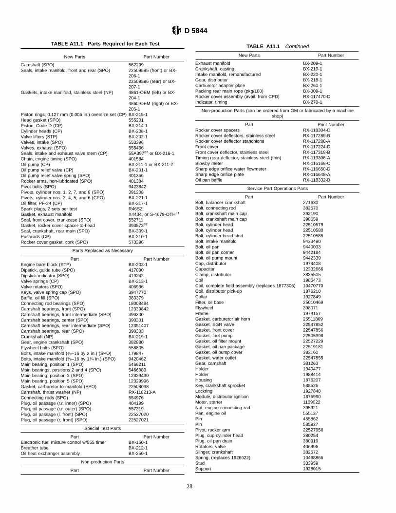
TABLE A11.1 Parts Required for Each Test
New Parts Part Number
Camshaft (SPO) 562299Seals, intake manifold, front and rear (SPO) 22509595 (front) or BX-
206-122509596 (rear) or BX-207-1
Gaskets, intake manifold, stainless steel (NP) 4861-OEM (left) or BX-204-14860-OEM (right) or BX-205-1
Piston rings, 0.127 mm (0.005 in.) oversize set (CP) BX-215-1Head gasket (SPO) 555201Piston, Code D (CP) BX-214-1Cylinder heads (CP) BX-208-1Valve lifters (STP) BX-202-1Valves, intake (SPO) 553396Valves, exhaust (SPO) 555456Seals, intake and exhaust valve stem (CP) 55A39727 or BX-216-1Chain, engine timing (SPO) 401584Oil pump (CP) BX-211-1 or BX-211-2Oil pump relief valve (CP) BX-201-1Oil pump relief valve spring (SPO) 401366Rocker arms, non-lubricated (SPO) 401384Pivot bolts (SPO) 9423842Pivots, cylinder nos. 1, 2, 7, and 8 (SPO) 391208Pivots, cylinder nos. 3, 4, 5, and 6 (CPO) BX-221-1Oil filter, PF-24 (CP) BX-217-1Spark plugs, 2 sets per test R46SZGasket, exhaust manifold X4434, or S-4679-OTH31
Seal, front cover, crankcase (SPO) 552711Gasket, rocker cover spacer-to-head 39357332
Seal, crankshaft, rear main (SPO) BX-309-1Pushrods (CP) BX-210-1Rocker cover gasket, cork (SPO) 573396
Parts Replaced as Necessary
Part Part NumberEngine bare block (STP) BX-203-1Dipstick, guide tube (SPO) 417090Dipstick indicator (SPO) 419242Valve springs (CP) BX-213-1Valve rotators (SPO) 406996Keys, valve spring cap (SPO) 3947770Baffle, oil fill (SPO) 383379Connecting rod bearings (SPO) 18008494Camshaft bearings, front (SPO) 12339842Camshaft bearings, front intermediate (SPO) 390300Camshaft bearings, center (SPO) 390301Camshaft bearings, rear intermediate (SPO) 12351407Camshaft bearings, rear (SPO) 390303Crankshaft (NP) BX-219-1Gear, engine crankshaft (SPO) 382880Flywheel bolts (SPO) 558805Bolts, intake manifold (3⁄8–16 by 2 in.) (SPO) 179847Bolts, intake manifold (3⁄8–16 by 11⁄4 in.) (SPO) 9420462Main bearing, position 1 (SPO) 5466211Main bearings, positions 2 and 4 (SPO) 5466089Main bearing, position 3 (SPO) 12329430Main bearing, position 5 (SPO) 12329996Gasket, carburetor-to-manifold (SPO) 22508038Camshaft, thrust washer (NP) RX-118213-AConnecting rods (SPO) 554976Plug, oil passage (r.r. inner) (SPO) 404199Plug, oil passage (r.r. outer) (SPO) 557319Plug, oil passage (l. front) (SPO) 22527020Plug, oil passage (r. front) (SPO) 22527021
Special Test Parts
Part Part NumberElectronic fuel mixture control w/555 timer BX-150-1Breather tube BX-212-1Oil heat exchanger assembly BX-250-1
Non-production Parts
Part Part Number
TABLE A11.1 Continued
New Parts Part Number
Exhaust manifold BX-209-1Crankshaft, casting BX-219-1Intake manifold, remanufactured BX-220-1Gear, distributor BX-218-1Carburetor adapter plate BX-260-1Packing rear main rope (pkg/100) BX-309-1Rocker cover assembly (avail. from CPD) RX-117470-DIndicator, timing BX-270-1
Non-production Parts (can be ordered from GM or fabricated by a machineshop)
Part Print NumberRocker cover spacers RX-118304-DRocker cover deflectors, stainless steel RX-117289-BRocker cover deflector stanchions RX-117288-AFront cover RX-117224-DFront cover deflector, stainless steel RX-117319-BTiming gear deflector, stainless steel (thin) RX-119306-ABlowby meter RX-116169-CSharp edge orifice water flowmeter RX-116650-DSharp edge orifice plate RX-116649-AOil pan baffle RX-118332-B
Service Part Operations Parts
Part Part NumberBolt, balancer crankshaft 271630Bolt, connecting rod 382570Bolt, crankshaft main cap 392190Bolt, crankshaft main cap 398659Bolt, cylinder head 22510579Bolt, cylinder head 22510580Bolt, cylinder head stud 22510585Bolt, intake manifold 9423490Bolt, oil pan 9440033Bolt, oil pan corner 9442184Bolt, oil pump mount 9442339Cap, distributor 1974408Capacitor 12332666Clamp, distributor 3835505Coil 1985473Coil, complete field assembly (replaces 1877306) 10470770Coil, distributor pick-up 1876210Collar 1927849Filter, oil base 25010469Flywheel 398071Frame 1974157Gasket, carburetor air horn 25511809Gasket, EGR valve 22547852Gasket, front cover 22547856Gasket, fuel pump 22505998Gasket, oil filter mount 22527229Gasket, oil pan package 22519181Gasket, oil pump cover 382160Gasket, water outlet 22547855Gear, camshaft 381263Holder 1940477Holder 1988414Housing 1876207Key, crankshaft sprocket 588526Lockring 1927848Module, distributor ignition 1875990Motor, starter 1109022Nut, engine connecting rod 395921Pan, engine oil 555137Pin 455862Pin 585927Pivot, rocker arm 22527956Plug, cup cylinder head 380254Plug, oil pan drain 380919Rotators, valve 406996Slinger, crankshaft 382572Spring, (replaces 1926622) 10498866Stud 333959Support 1928015
D 5844
28

TABLE A11.1 Continued
New Parts Part Number
Washer, intake manifold bolt 3899696
TABLE A11.1 Continued
New Parts Part Number
Weights, distributor shaft 1893888
A12. COOLANT CALIBRATION STANDARDS
A12.1 Prepare coolant calibration standards containing 35,40, and 45 % by volume glycol in distilled water plus thespecified additive concentrations (see 7.3.1).
A12.1.1 Control temperature during preparation at 806 1°F(26.76 0.6°C).
A12.2 Generate calibration curves by determining thespecific gravity of the three standards at various temperatures.
A12.3 Use an ASTM Hydrometer, Model 112-H, with a1.050 to 1.100 range, to determine the specific gravity of boththe calibration standards and the actual engine coolant mix-tures. This can be obtained from the H-B Instrument Co.49
A13. DIPSTICK CALIBRATION
A13.1 Use a graduated dipstick method to determine the oillevel.
A13.1.1 Develop a curve of dipstick measurement versusoil level at 1206 5°F (48.96 2.8°C).A13.1.1.1 The oil level should first be adjusted to be at the
indicated full mark on the dipstick in an engine mounted asdescribed in 8.4.2.
A13.1.1.2 Withdraw the oil in increments of 2 or 4 fluid oz(59 or 118 mL), and record the resulting dipstick measure-ments. Develop a curve of dipstick measurements versus oilvolume removed from these data.
A13.2 Although not linear,1⁄32 in. (0.79 mm) on thedipstick is equivalent to about 1 oz (29.5 mL) of oil.
A14. CALCULATION OF SEVERITY ADJUSTMENTS
A14.1 There is an accepted method for determining if aseverity adjustment (SA) should be applied to non-reference oiltest results.
A14.1.1 An exponentially weighted moving average(EWMA) of reference oil test results is the basis for such adetermination.A14.1.2 If the EWMA for a valid standard reference test
exceeds a statistically derived control limit, then an SA will bein effect and shall be applied to ensuing non-reference oil testresults until the next valid standard reference test.
A14.2 The following example illustrates the computationof the EWMA and SA values, and the application of the SAvalue:
A14.2.1 Assume that a valid standard reference oil test hasjust been completed on Reference Oil A. Assume that thecontrol limit is 0.600 (this is in standard deviation units).A14.2.2 The mean average rust value for previous tests
with Reference Oil A test is 8.256, and the standard deviationfor that oil is 0.159. The actual average rust test result for thetest just completed with Reference Oil A was 8.99.A14.2.3 First, a standardized test result (in standard devia-
tion units) is calculated for the test just completed by dividingthe difference between the actual test result and the mean valueby the standard deviation; that is, (8.99 − 8.526)/0.1595 2.918.
A14.2.4 The EWMA prior to this latest standardized testresult is 0.791, and experience has shown that the prior EWMAvalue should receive more weight (80 %) than the newest result(20 %) when calculating the new EWMA value.A14.2.5 Thus, the calculated new EWMA value is
0.8(0.791) + 0.2(2.918)5 1.216.A14.2.6 Since 1.216 exceeds the control limit of 0.600, it is
necessary to calculate and apply an SA on ensuing non-reference oil tests.A14.2.7 Converting the 1.216 EWMA value from standard
deviation units to average rust units, requires multiplying the1.216 value by 0.12 (the pooled standard deviation for thereference oils used in the test method); that is,0.123 1.2165 0.1459.A14.2.8 Since the new EWMA is on themild side of the
control limit, it is necessary to correct ensuing non-referenceoil test results by subtracting the SA. Thus, multiply the SAby − 1 and round to two places after the decimal point; thatis, − 13 0.14595 −0.15.
A14.3 Enter this SA value on the Test Result Summarypage (Fig. 7) of the test report, and add the Average Rust valueto obtain the Adjusted Rust value.
A14.4 The above is just an example. Contact the TMC forthe necessary factors needed to make an actual calculation ofseverity adjustment.
49 Available from H-B Instrument Co., 4303 N. American St., Philadelphia, PA19140.
D 5844
29
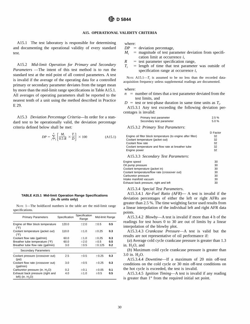
A15. OPERATIONAL VALIDITY CRITERIA
A15.1 The test laboratory is responsible for determiningand documenting the operational validity of every standardtest.
A15.2 Mid-limit Operation for Primary and SecondaryParameters—The intent of this test method is to run thestandard test at the mid point of all control parameters. A testis invalid if the average of the operating data for a controlledprimary or secondary parameter deviates from the target meanby more than the mid-limit range specifications in Table A15.1.All averages of operating parameters shall be reported to thenearest tenth of a unit using the method described in PracticeE 29.
A15.3 Deviation Percentage Criteria—In order for a stan-dard test to be operationally valid, the deviation percentagecriteria defined below shall be met:
DP5 (i 5 1
n F Mi
0.5R 3TiDG 3 100 (A15.1)
where:DP 5 deviation percentage,Mi 5 magnitude of test parameter deviation from specifi-
cation limit at occurrencei,R 5 test parameter specification range,Ti 5 length of time that test parameter was outside of
specification range at occurrencei,
NOTE A15.1—Ti is assumed to be no less than the recorded data-acquisition frequency unless supplemental readings are documented.
where:n 5 number of times that a test parameter deviated from the
test limits, andD 5 test or test-phase duration in same time units asTi.A15.3.1 Any test exceeding the following deviation per-
centages is invalid:Primary test parameter 2.5 %Secondary test parameter 5.0 %
A15.3.2 Primary Test Parameters:D Factor
Engine oil filter block temperature (to engine after filter) 32Coolant temperature (jacket out) 32Coolant flow rate 32Coolant temperature and flow rate at breather tube 32Engine power 32
A15.3.3 Secondary Test Parameters:Engine speed 30Oil pump pressure 30Coolant temperature (jacket in) 30Coolant temperature/flow rate (crossover out) 30Carburetor pressure 30Intake manifold vacuum 30Exhaust back pressure, right and left 30
A15.3.4 Special Test Parameters.A15.3.4.1Air-Fuel Ratio (AFR)— A test is invalid if the
deviation percentages of either the left or right AFRs aregreater than 2.5 %. The time weighting factor used results froma linear interpolation of the individual left and right AFR datapoints.A15.3.4.2Blowby—A test is invalid if more than 4 h of the
readings for test hours 0 to 30 are out of limits by a linearinterpolation of the blowby plot.A15.3.4.3Crankcase Pressure—A test is valid but the
results are not representative of oil performance if:(a) Average cold cycle crankcase pressure is greater than 1.3
in. H2O, and(b) Maximum cold cycle crankcase pressure is greater than
3.0 in. H2O.A15.3.4.4Downtime—If a maximum of 20 min off-test
conditions on the cold cycle or 30 min off-test conditions onthe hot cycle is exceeded, the test is invalid.A15.3.4.5 Ignition Timing—A test is invalid if any reading
is greater than 1° from the required initial set point.
TABLE A15.1 Mid-limit Operation Range Specifications(in.-lb units only)
NOTE 1—The boldfaced numbers in the table are the mid-limit rangespecifications.
Primary Parameters SpecificationSpecification
RangeMid-limit Range
Engine oil filter block temperature(°F)
120.0 62.0 60.5 0.5
Coolant temperature (jacket out)(°F)
110.0 61.0 60.25 0.3
Coolant flow rate (gal/min) 60.0 61.0 60.25 0.3Breather tube temperature (°F) 60.0 62.0 60.5 0.5Breather tube flow rate (gal/min) 3.0 60.5 60.125 0.2
Secondary Parameters
Coolant pressure (crossover out)(psi)
2.5 60.5 60.25 0.3
Coolant flow rate (crossover out)(gal/min)
3.0 60.5 60.25 0.3
Carburetor pressure (in. H2O) 0.2 60.1 60.05 0.1Exhaust back pressure (right andleft) (in. H2O)
4.0 61.0 60.5 0.5
D 5844
30

A16. REPORTING TEST METHOD D 5844 RESULTS
A16.1 Use the standardized report form package detailed inA16.2 to report all Test Method D 5844 non-reference oil andreference oil results.
A16.2 Test Report Forms with Data Dictionary VariableMneumonics—The following report forms contain field namesfor all reported variables. These variables are for use in datacommunication as being developed by the Data Communica-tion Task Force. See Figs. A16.1-A16.11.
A16.3 Test Report Variable Data Dictionary—The follow-ing is a complete data dictionary of the field names used inA16.2. See Fig. A16.12.
A16.4 Reporting Reference Oil Test Results:
A16.4.1 Reporting Preliminary Reference Oil TestResults—Report preliminary reference oil test results to theTMC by way of telecopier facsimile using forms shown in Fig.A16.1, Figs. A16.5-A16.9, and Fig. A16.11.
A16.4.2 Final Reference Oil Test Report—A final referenceoil test report shall include all forms, with Fig. A16.3 omitted,in the standardized report form package. See Fig. A16.1, Fig.A16.2, and Figs. A16.4-A16.11.
A16.5 Reporting Non-reference Oil Test Results—A finalnon-reference oil test report shall include all forms, with Fig.A16.2 omitted, in the standardized report form package. SeeFig. A16.1, and Figs. A16.3-A16.11.
D 5844
31

FIG. A16.1 Validity Statement
D 5844
32
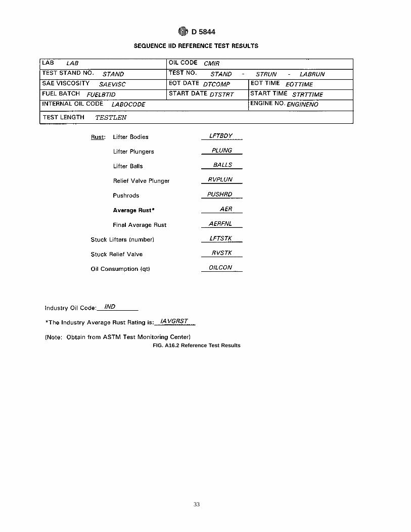
FIG. A16.2 Reference Test Results
D 5844
33
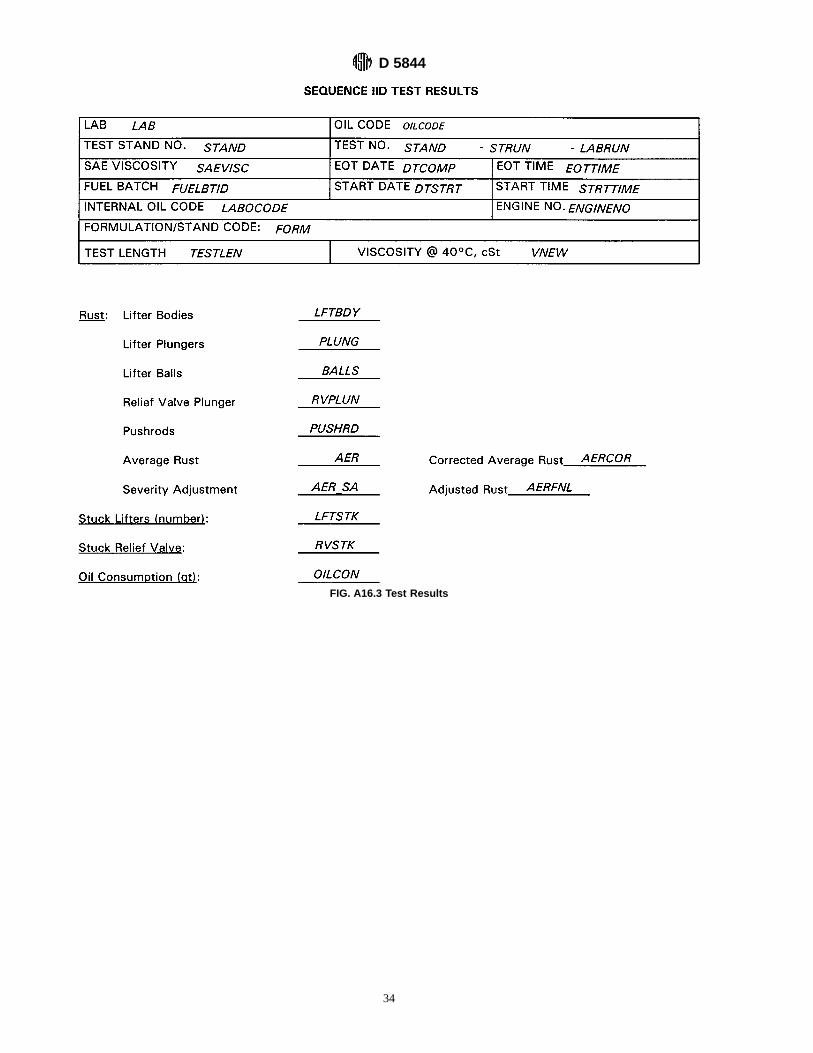
FIG. A16.3 Test Results
D 5844
34

FIG. A16.4 Downtime and Outlier Report
D 5844
35

FIG. A16.5 Hardware Information
D 5844
36

FIG. A16.6 Deviation Percentage & Mid-limit Operation Report
D 5844
37

FIG. A16.7 Operational Summary
D 5844
38

FIG. A16.8 Blowby Plot
D 5844
39
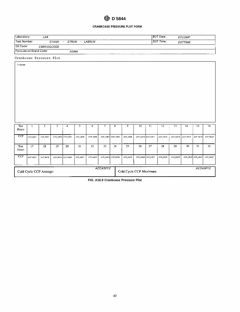
FIG. A16.9 Crankcase Pressure Plot
D 5844
40

FIG. A16.10 Rust Rating Worksheet
D 5844
41

FIG. A16.11 Characteristics of the Data Acquisition System
D 5844
42

FIG. A16.12 Data Dictionary
D 5844
43

FIG. A16.12 (continued)
D 5844
44
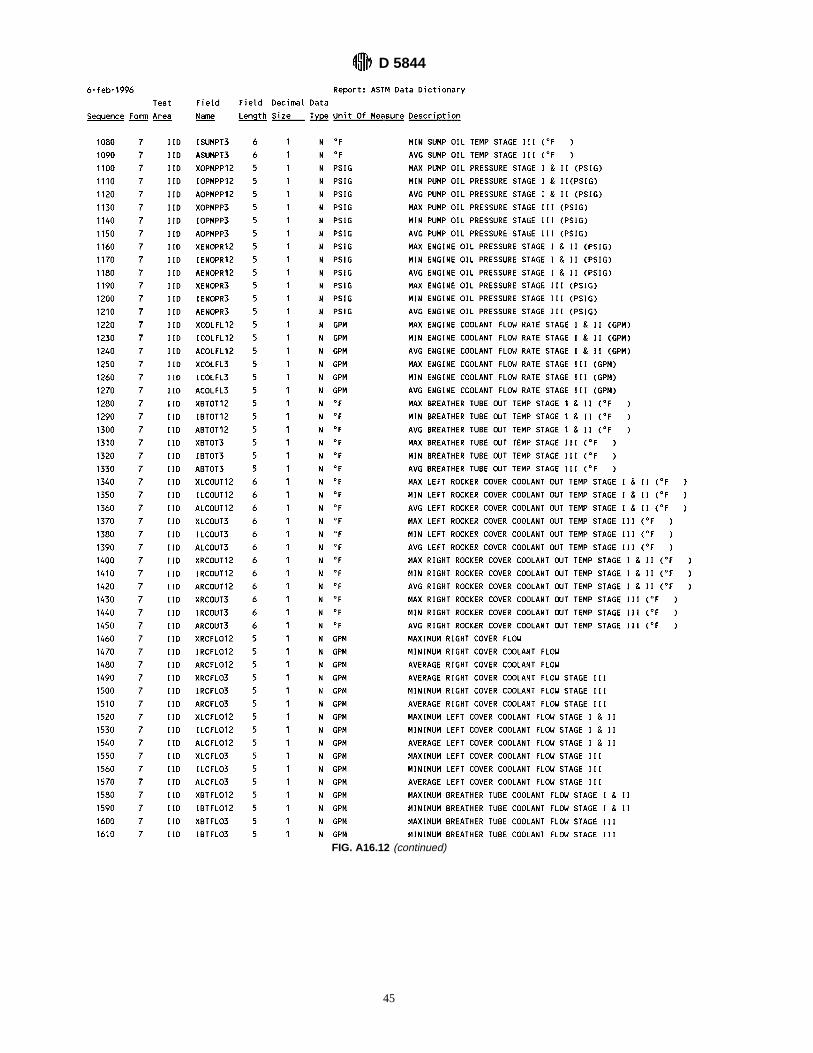
FIG. A16.12 (continued)
D 5844
45

FIG. A16.12 (continued)
D 5844
46
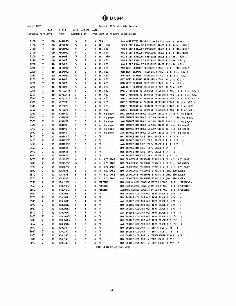
FIG. A16.12 (continued)
D 5844
47
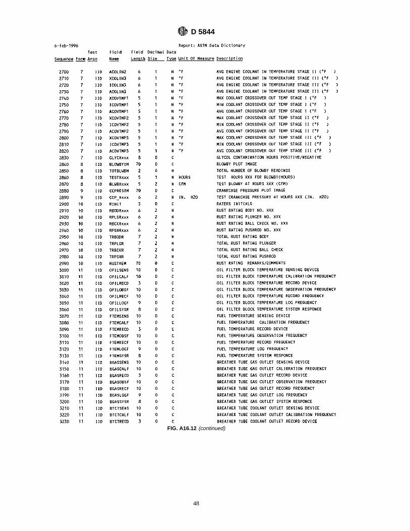
FIG. A16.12 (continued)
D 5844
48

FIG. A16.12 (continued)
D 5844
49

FIG. A16.12 (continued)
D 5844
50

APPENDIX
(Nonmandatory Information)
X1. TEST MONITORING CENTER INFORMATION LETTERS
X1.1 Occasionally, it is necessary to revise the test method,and notify the industry of the revision, prior to obtainingnormal ASTM consensus. In such a case, the Test MonitoringCenter immediately issues an Information Letter to the indus-try. Subsequently, the Information Letter is balloted by Sub-committee D02.B (generally, just prior to each semiannualCommittee D-2 meeting), followed by a ballot of the MainCommittee members. By this means, the Society due processprocedures are applied to an Information Letter.
X1.2 The Test Monitoring Center receives assistance in theissue of an Information Letter, particularly from the test
method’s Surveillance Panel and the test developer (the repre-sentative of the engine manufacturer, whose engine is used inthe test method).
X1.3 Authority for the issuance of Information Letters wasgiven by the ASTM Committee on Technical CommitteeOperations in 1984, as follows:“COTCO recognizes that D-2 has a unique and complexsituation. The use of Information Letters is approved providingeach letter contains a disclaimer to the effect that such has notobtained ASTM consensus. These Information Letters shouldbe moved to such consensus as rapidly as possible.”
The American Society for Testing and Materials takes no position respecting the validity of any patent rights asserted in connectionwith any item mentioned in this standard. Users of this standard are expressly advised that determination of the validity of any suchpatent rights, and the risk of infringement of such rights, are entirely their own responsibility.
This standard is subject to revision at any time by the responsible technical committee and must be reviewed every five years andif not revised, either reapproved or withdrawn. Your comments are invited either for revision of this standard or for additional standardsand should be addressed to ASTM Headquarters. Your comments will receive careful consideration at a meeting of the responsibletechnical committee, which you may attend. If you feel that your comments have not received a fair hearing you should make yourviews known to the ASTM Committee on Standards, 100 Barr Harbor Drive, West Conshohocken, PA 19428.
FIG. A16.12 (continued)
D 5844
51