standard technical specifcation of ct...
TRANSCRIPT

STANDARD
TECHNICAL SPECIFCATION
Of
CT OPERATED ENERGY METERING CABINET
comprising of
100/5 Amps or 50/5 Amps Resin Cast Plug in Type
CTs,
160 Amps (setting at 100 A) or 100 Amps (setting at
50 A) MCCBs
and
LT CT Operated TOD Meter
And
Other Arrangement.
Technical Specification No.
CE/DIST/MSC-IV/T/0310, DTD. 09.03.2010.
STANDARDTECHNICAL SPECIFCATION Of CT OPERATED ENERGY METERING CABINET comprising of
100/5A or 50/5 A Resin Cast Plug in Type CTs, 160 Amps (setting at 100 A) or 100 Amps (setting at 50 A)
MCCBs and LT CT Operated TOD Meter And Other Arrangement
Technical Specification No. CE/DIST/MSC-IV/T/0310, DTD. 09.03.2010.
INDEX
SR. NO. DESCRIPTION PAGE NO.
1 SCOPE 1
2 APPLICATION 1
3 SERVICE CONDITIONS 1
4 STANDARDS 2
5 GENERAL TECHNICAL PARTICULARS 2
6 TECHNICAL SPECIFICATION FOR METER
a. SCOPE 2
b. APPLICABLE STANDARDS 2
c. GENERAL TECHNICAL PARTICULARS 3
d. CONSTRUCTIONAL REQUIREMENT / METER COVER & SEALING
ARRANGEMENT 4
e. COMMUNICATION CAPABILITY 6
f. SELF DIAGNOSTIC FEATURES 6
g. TOD TIMINGS 7
h. DEMAND INTEGRATION PERIOD 7
i. MD RESET 7
j. REAL TIME INTERNAL CLOCK (RTC) 7
k. TAMPER & FRAUD MONITORING FEATURES (ANTI TAMPER
FEATURES) 8
l. TAMPER EVENTS 8
m. DISPLAYS 11
n. QUANTITIES TO BE MEASURED & DISPLAYED 12
o. PERFORMANCE UNDER INFLUENCE QUANTITIES 17
p. OUTPUT DEVICE 17
q. TESTS 17
r. CONNECTION DIAGRAM AND TERMINAL MARKINGSPRE 19
s. MANUFACTURING PROCESS, ASSEMBLY AND TESTING 20
STANDARDTECHNICAL SPECIFCATION Of CT OPERATED ENERGY METERING CABINET comprising of
100/5A or 50/5 A Resin Cast Plug in Type CTs, 160 Amps (setting at 100 A) or 100 Amps (setting at 50 A)
MCCBs and LT CT Operated TOD Meter And Other Arrangement
Technical Specification No. CE/DIST/MSC-IV/T/0310, DTD. 09.03.2010.
t. COMPONENT SELECTION 22
u. ANNEXURE I 23
7 TECHNICAL SPECIFICATION FOR CURRENT TRANSFORMER (CT) 26
8 TECHNICAL SPECIFICATION FOR MOULDED CASE CIRCUIT
BREAKERS (MCCB) 26
9 TECHNICAL SPECIFICATION FOR ENCLOSURE (METERING
CABINET) 28
10 SAFETY ARRANGEMENT 30
11 TESTING & MANUFACTURING FACILITIES 30
12 TESTS & TEST CERTIFICATE 31
13 QUALITY ASSURANCE 32
14 QUALIFYING REQUIREMENTS 33
15 PROTOTYPE & DRAWINGS 34
16 GUARANTEE 34
17 INSPECTION 34
18 RANDIM SAMPLE TESTING 35
19 TENDER SAMPLE 35
20 SCHEDULES 35
21 SCHEDULE-C 37
22 ANNEXURE U-1 38
23 SCHEDULE-A (GTP on e-tendering) 39
24 DRAWINGS 47
STANDARDTECHNICAL SPECIFCATION Of CT OPERATED ENERGY METERING CABINET comprising of 100/5A or 50/5 A Resin Cast Plug in Type CTs, 160 Amps (setting at 100 A) or 100 Amps (setting at 50 A) MCCBs and LT
CT Operated TOD Meter And Other Arrangement
Technical Specification No. CE/DIST/MSC-IV/T/0310, DTD. 09.03.2010. Page 1 of 46
1.00 SCOPE
This Specification covers design, manufacture, testing at works, supply and
delivery of a sheet steel or SMC moulded cabinet comprising of 100 /5 Amps or 50
/ 5 Amps resin cast CTs with plug in type arrangement, 160 Amps (setting at 100
Amps) or 100 Amps (setting at 50 A) MCCBs and LT AC, 3 Phase, 4 Wire, LT CT
operated fully Static Tri-Vector Energy Meters for measurement of different
electrical parameters and other arrangement as per the specification. The system
shall be AC, 3 phase, 4 wire, 415 Volts, 50 Hz with effectively grounded neutral
with CT ratios of 100 / 5 Amps or 50/5 Amps.
2.00 APPLICATION
For use in LT Electrical Distribution System in the State of Maharashtra.
3.00 SERVICE CONDITIONS
The equipments to be supplied against this specification shall be suitable for
satisfactory continuous operation under the following tropical conditions.
Environmental Conditions
a) Maximum ambient temperature 550C
b) Maximum ambient temperature in shade 450C
c) Minimum temperature of air in shade 350C
d) Maximum daily average temperature 400C
e) Maximum yearly weighted average temperature 320C
f) Relative Humidity 10 to 95 %
g) Maximum Annual rainfall 1450 mm
h) Maximum wind pressure 150 kg/m2
i) Maximum altitude above mean sea level 1000 meters
j) Isoceraunic level 50 days/year
k) Seismic level (Horizontal acceleration) 0.3 g
l) Climate: - Moderately hot and humid tropical climate conducive to rust and fungus growth.
As per IS 14697-1999 (reaffirmed 2004), the meter to perform satisfactorily under
Non-Air Conditioned environment (within stipulations of IS)
Meter body shall conform to IP51 degree of protection. For outdoor use meter shall
be installed in sealed enclosure conforming to IP 55.
The meter shall be suitably designed for satisfactory operation under the hot and
hazardous tropical climate conditions and shall be dust and vermin proof. All the
parts and surface, which are subject to corrosion, shall either be made of such
STANDARDTECHNICAL SPECIFCATION Of CT OPERATED ENERGY METERING CABINET comprising of 100/5A or 50/5 A Resin Cast Plug in Type CTs, 160 Amps (setting at 100 A) or 100 Amps (setting at 50 A) MCCBs and LT
CT Operated TOD Meter And Other Arrangement
Technical Specification No. CE/DIST/MSC-IV/T/0310, DTD. 09.03.2010. Page 2 of 46
material or shall be provided with such protective finish, which provided suitable
protection to them from any injurious effect of excessive humidity.
4.00 STANDARDS
Unless otherwise modified in this specification:
(a) The enclosure box shall comply with IS: 13947 /1993 & IS: 13410 amended
upto date.
(b) The Electronic Energy Meter shall conform to IS: 14697/1999 or IEC: 687 or its
latest version thereof.
(c) The CT shall conform to IS: 2705/1992 or its latest version thereof.
(d) The MCCB shall comply with IS: 13947 /1993 amended upto date.
(e) MCCB, CT and meters having relevant BIS certification and ISO certification
would be preferred.
5.00 GENERAL TECHNICAL PARTICULARS
5.01 These cabinets are to be supplied as complete units consisting of 3 phase 4 wire
100 / 5 Amps or 50 / 5 Amps LT CT Operated TOD Energy Meters along with
Resin cast CTs with plug in type arrangement and MCCBs in sheet steel / SMC
moulded cabinet duly wired as shown in the general arrangement drawings No.
DIST /MM – IV / CTMTR / 2008 / 01, Sheet 1/3, 2/3 & 3/3. The supply shall be
as per final approved drawings.
5.02 Tenderer shall submit Type Test Reports for offered Meter, Resin cast CTs with
plug in type arrangement, MCCB & CT operated metering unit of each rating, along
with offer, failing which the offer shall be rejected.
5.03 All the Type Test Reports shall be within the period of Five Years from the date of
opening of the Tender.
6.00 TECHNICAL SPECIFICATION FOR LT CT OPERATED TOD METERS.
6.01 SCOPE
This specification covers design, manufacturing, testing, supply and delivery of
LT AC, 3 Phase, 4 Wire, LT CT operated fully static Tri-Vector Energy Meters for
measurement of different electrical parameters listed elsewhere in the document
including Active Energy (KWH), Reactive Energy (KVARH) and Apparent Energy
(KVAH) etc.
6.02 APPLICABLE STANDARDS
The Meter shall conform to the requirements of IS: 14697/1999 (amended up to
date) or IEC: 687; CBIP Tech-Report-88 amended up to date for AC Static
Transformer operated Watt Hour & VAR-Hour meters (class 0.5S) and other
relevant IS specifications . The specifications given in this document supersedes
the relevant clauses of IS: 14697 / 1999 (amended up to date) wherever
applicable.
STANDARDTECHNICAL SPECIFCATION Of CT OPERATED ENERGY METERING CABINET comprising of 100/5A or 50/5 A Resin Cast Plug in Type CTs, 160 Amps (setting at 100 A) or 100 Amps (setting at 50 A) MCCBs and LT
CT Operated TOD Meter And Other Arrangement
Technical Specification No. CE/DIST/MSC-IV/T/0310, DTD. 09.03.2010. Page 3 of 46
IS: 15707 Specification for Testing, evaluation, installation & maintenance of AC
Electricity Meters-Code of Practice.
The meter must bear ISI Mark.
The equipment meeting with the requirements of other authoritative standards,
which ensure equal or better quality than the standard mentioned above, also
shall be considered. For conflict related with other parts of the specification, the
order of priority shall be – i) This technical specification, ii) IS: 14697 /1999
(reaffirmed 2004).
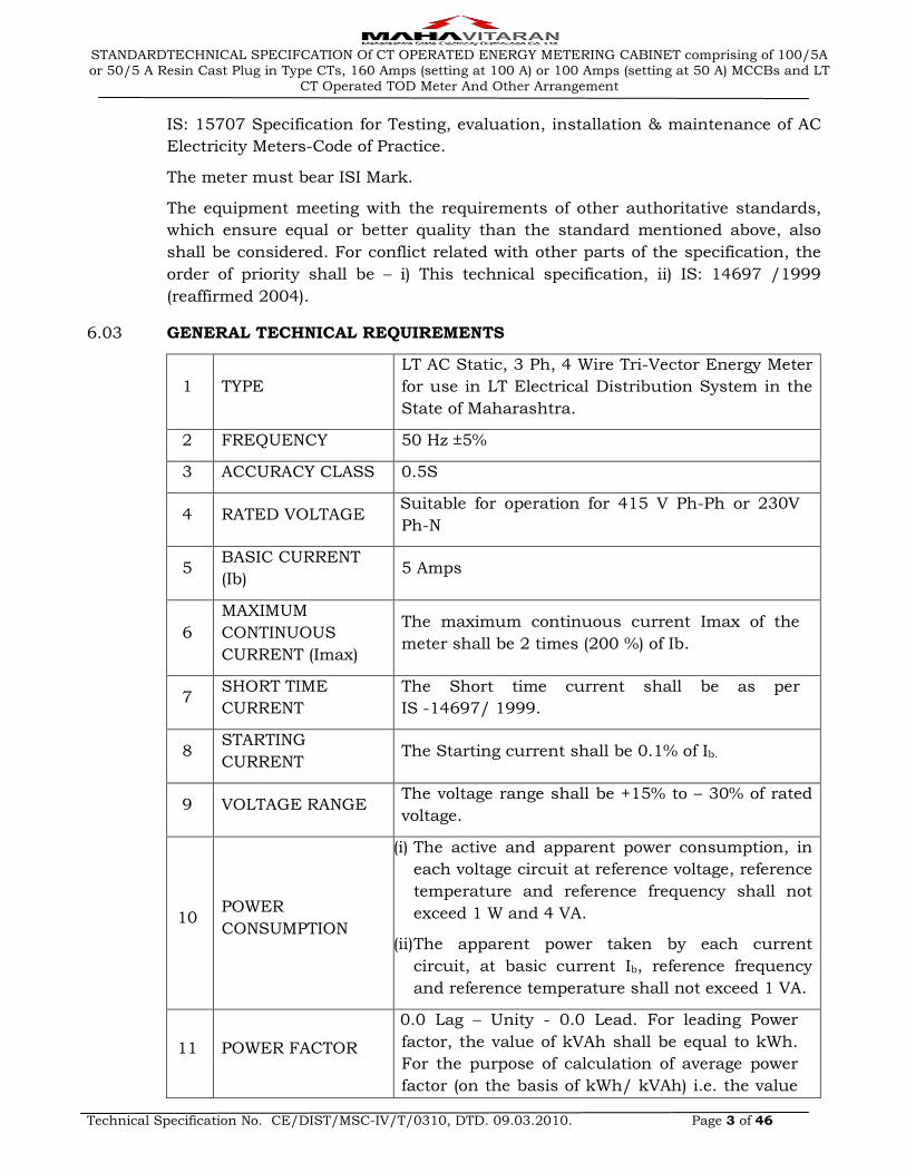
6.03 GENERAL TECHNICAL REQUIREMENTS
1 TYPE
LT AC Static, 3 Ph, 4 Wire Tri-Vector Energy Meter
for use in LT Electrical Distribution System in the
State of Maharashtra.
2 FREQUENCY 50 Hz ±5%
3 ACCURACY CLASS 0.5S
4 RATED VOLTAGE Suitable for operation for 415 V Ph-Ph or 230V
Ph-N
5 BASIC CURRENT
(Ib) 5 Amps
6
MAXIMUM
CONTINUOUS
CURRENT (Imax)
The maximum continuous current Imax of the
meter shall be 2 times (200 %) of Ib.
7 SHORT TIME
CURRENT
The Short time current shall be as per
IS -14697/ 1999.
8 STARTING
CURRENT The Starting current shall be 0.1% of Ib.
9 VOLTAGE RANGE The voltage range shall be +15% to – 30% of rated
voltage.
10 POWER
CONSUMPTION
(i) The active and apparent power consumption, in
each voltage circuit at reference voltage, reference
temperature and reference frequency shall not
exceed 1 W and 4 VA.
(ii) The apparent power taken by each current
circuit, at basic current Ib, reference frequency
and reference temperature shall not exceed 1 VA.
11 POWER FACTOR
0.0 Lag – Unity - 0.0 Lead. For leading Power
factor, the value of kVAh shall be equal to kWh.
For the purpose of calculation of average power
factor (on the basis of kWh/ kVAh) i.e. the value
STANDARDTECHNICAL SPECIFCATION Of CT OPERATED ENERGY METERING CABINET comprising of 100/5A or 50/5 A Resin Cast Plug in Type CTs, 160 Amps (setting at 100 A) or 100 Amps (setting at 50 A) MCCBs and LT
CT Operated TOD Meter And Other Arrangement
Technical Specification No. CE/DIST/MSC-IV/T/0310, DTD. 09.03.2010. Page 4 of 46
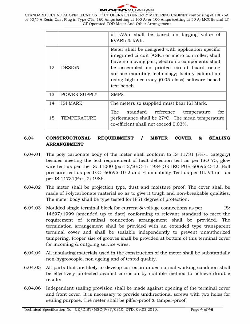
of kVAh shall be based on lagging value of
kVARh & kWh.
12 DESIGN
Meter shall be designed with application specific
integrated circuit (ASIC) or micro controller; shall
have no moving part; electronic components shall
be assembled on printed circuit board using
surface mounting technology; factory calibration
using high accuracy (0.05 class) software based
test bench.
13 POWER SUPPLY SMPS
14 ISI MARK The meters so supplied must bear ISI Mark.
15 TEMPERATURE
The standard reference temperature for
performance shall be 270C. The mean temperature
co-efficient shall not exceed 0.03%.
6.04 CONSTRUCTIONAL REQUIREMENT / METER COVER & SEALING
ARRANGEMENT
6.04.01 The poly carbonate body of the meter shall conform to IS 11731 (FH-1 category)
besides meeting the test requirement of heat deflection test as per ISO 75, glow
wire test as per the IS: 11000 (part 2/SEC-1) 1984 OR IEC PUB 60695-2-12, Ball
pressure test as per IEC--60695-10-2 and Flammability Test as per UL 94 or as
per IS 11731(Part-2) 1986.
6.04.02 The meter shall be projection type, dust and moisture proof. The cover shall be
made of Polycarbonate material so as to give it tough and non-breakable qualities.
The meter body shall be type tested for IP51 degree of protection.
6.04.03 Moulded single terminal block for current & voltage connections as per IS:
14697/1999 (amended up to date) conforming to relevant standard to meet the
requirement of terminal connection arrangement shall be provided. The
termination arrangement shall be provided with an extended type transparent
terminal cover and shall be sealable independently to prevent unauthorized
tampering. Proper size of grooves shall be provided at bottom of this terminal cover
for incoming & outgoing service wires.
6.04.04 All insulating materials used in the construction of the meter shall be substantially
non-hygroscopic, non ageing and of tested quality.
6.04.05 All parts that are likely to develop corrosion under normal working condition shall
be effectively protected against corrosion by suitable method to achieve durable
results.
6.04.06 Independent sealing provision shall be made against opening of the terminal cover
and front cover. It is necessary to provide unidirectional screws with two holes for
sealing purpose. The meter shall be pilfer-proof & tamper-proof.

STANDARDTECHNICAL SPECIFCATION Of CT OPERATED ENERGY METERING CABINET comprising of 100/5A or 50/5 A Resin Cast Plug in Type CTs, 160 Amps (setting at 100 A) or 100 Amps (setting at 50 A) MCCBs and LT
CT Operated TOD Meter And Other Arrangement
Technical Specification No. CE/DIST/MSC-IV/T/0310, DTD. 09.03.2010. Page 5 of 46
6.04.07 The meter shall have Poly-carbonate transparent base and transparent cover of
Poly-carbonate material, which shall be ultra-sonically welded (continuous welding)
so that once the meter is manufactured and tested at factory; it shall not be
possible to open the cover at site except the terminal cover. The thickness of
material for meter cover and base shall be 2 mm (minimum).
6.04.08 The terminal block, the terminal cover and the meter case shall ensure reasonable
safety against the spread of fire. They shall not be ignited by thermal overload of
live parts in contact with them.
6.04.09 The meter shall be completely factory sealed except the terminal block cover. The
provision shall be made on the Meter for at least two seals to be put by utility user.
The Terminal cover shall be transparent with one side hinge with sealing
arrangement.
6.04.10 The Push button shall be provided for high-resolution reading & display,
parameters.
6.04.11 The meter shall have a suitable test output device for testing meter. Preferably the
blinking LED or other similar device like blinking LCD shall be provided. The test
output device shall have constant pulse rate i.e. Pulse/KWh and pulse/KVARh and
its value (meter constant) shall be indelibly printed on the name plate.
6.04.12 The meter accuracy shall not be affected by external AC / DC / permanent
magnetic field on all the sides of meter, i.e. front, sides, top and bottom of the
meter as per CBIP Technical Report 88 with latest amendments. If the meter gets
affected under influence of any abnormal magnetic field, then the same shall be
recorded as magnetic tamper event with date & time stamping and the meter shall
record energy considering Imax and reference voltage at unity power factor in all
the three phases.
6.04.13 CTs are to be provided with magnetic shielding and they shall be tested separately
prior to Assembly.
6.04.14 The meter shall also be capable to withstand and shall not get damaged if phase-
to-phase voltage is applied between phases & neutral for five minutes.
6.04.15 In meter, power supply unit shall be micro control type instead of providing
transformer and then conversion to avoid magnetic influence.
6.04.16 Non-specified display parameter in the meter shall be blocked and it shall not be
accessible for reprogramming at site.
6.04.17 Complete metering system shall not be affected by the external electromagnetic
interference such as electrical discharge of cables and capacitors, harmonics,
electrostatic discharges, external magnetic fields and DC current in AC supply etc.
The Meter shall meet the requirement of CBIP Tech-report 88 (amended up to
date).
6.04.18 The meter shall withstand any type of High Voltage and High Frequency surges,
which are similar to the surges produced by induction coil type instruments
without affecting the accuracy of the meter. Likewise the accuracy of the meter
STANDARDTECHNICAL SPECIFCATION Of CT OPERATED ENERGY METERING CABINET comprising of 100/5A or 50/5 A Resin Cast Plug in Type CTs, 160 Amps (setting at 100 A) or 100 Amps (setting at 50 A) MCCBs and LT
CT Operated TOD Meter And Other Arrangement
Technical Specification No. CE/DIST/MSC-IV/T/0310, DTD. 09.03.2010. Page 6 of 46
shall not be affected with the application of abnormal voltage / frequency
generating device such as spark discharge of approximately 35 KV. The meter shall
be tested by feeding the output of this device to meter in any of the following
manner for 10 minutes
i) On any of the phases or neutral terminals
ii) On any connecting wires of the meter (Voltage discharge with 0-10 mm spark
gap)
iii) At any place in load circuit. The accuracy of meter shall be checked before and
after the application of above device.
6.04.19 COMMUNICATION CAPABILITY
The meter shall be provided with two ports for communication of the measured /
collected data, i.e. a hardware port compatible with RS 232 or RS 485
specifications (RJ - 11 / RJ 45 type is also acceptable) which shall be used to
transfer and export data for remote access through suitable Modem (GPRS / GSM
/ EDGE / CDMA / PSTN / LPR) and an Optical port. This port shall be used for
local data downloading through a HHU like CMRI, Laptop and PC and if possible,
through line carrier communication. RS 232 or RS 485 port on terminal block is
also acceptable. Sealing arrangement for Optical & RS 232 or RS 485 port as
required shall be provided. Both the ports shall support the default and minimum
baud rate of 9600 bps.
6.04.20 SELF DIAGNOSTIC FEATURES
6.04.20.1 The meter shall keep log in its memory for unsatisfactory functioning or
nonfunctioning of Real Time Clock battery, also it shall be recorded and indicated
in reading file at base computer software computer.
6.04.20.2 All display segments: "LCD Test" display shall be provided for this purpose.
6.04.20.3 The meter shall have facility to read the default parameters during power supply
failure. An internal maintenance free battery (Ni-mh or Li-ion or NICD) of long life
of 15 years shall be provided for the same. A suitable push button arrangement for
activation of battery shall be provided. This battery may be of INTERNAL OR
external type with inductive coupling arrangement. External Battery is to be
provided with inbuilt charger, in the ratio of one battery pack per 50 nos. meters.
6.04.21 Wire / Cable less design: The meter PCB shall be wire less to avoid improper and
loose connections/ contacts.
6.04.22 PCB used in meter shall be made by Surface Mounting Technology.
6.04.23 The RTC battery & the battery for display in case of power failure shall be separate.
6.04.24 The data stored in the meters shall not be lost in the event of power failure. The
meter shall have sufficient Non Volatile Memory (NVM) for recording history of
billing parameters (Cumulative kWh at the time of reset and kVAMD) for last 6
months, which does not need any battery backup. The NVM shall have a minimum
retention period of 10 years.
STANDARDTECHNICAL SPECIFCATION Of CT OPERATED ENERGY METERING CABINET comprising of 100/5A or 50/5 A Resin Cast Plug in Type CTs, 160 Amps (setting at 100 A) or 100 Amps (setting at 50 A) MCCBs and LT
CT Operated TOD Meter And Other Arrangement
Technical Specification No. CE/DIST/MSC-IV/T/0310, DTD. 09.03.2010. Page 7 of 46
6.05 TOD TIMINGS
There shall be a provision for at least 6 (Six) TOD time zones for energy and
demand. The number and timings of these TOD time Zones shall be programmable.
At present the time zones shall be programmed as below:
TIME ZONE "A" : 00-00 to 06.00 hrs & 22.00 to 24.00 hrs.
TIME ZONE "B" : 06.00 to 09.00 hrs & 12.00 to 18.00 hrs.
TIME ZONE "C" : 09.00 to 12.00 hrs.
TIME ZONE “D” : 18.00 to 22.00 hrs.
6.06 DEMAND INTEGRATION PERIOD
The maximum demand integration period shall be set at 15 minute or 30 minute
as per requirement.
The data stored in the array shall be the average value for the captured time block
and stored at the end of that block, except for energy values. The energy entries are
the consumption during respective capture time block and posted at the end of
that block. The array of data shall be retained inside the meter memory for the last
22 days for a capture period of 15 minutes or for the last 45 days for a capture
period of 30 minutes. The storage days can be expanded by choosing less number
of parameters.
6.07 MD RESET
It shall be possible to reset MD by the following options:
i) Communication driven reset through hand held terminal (HHU) / CMRI / PC /
LAPTOP.
ii) Local push button with sealing facility.
iii) Auto reset at 24:00 hrs at the end of each billing cycle. Automatic reset at the
end of certain predefined period (say, end of the month). - This option shall be
blocked by default and made programmable through hand held terminal (HHU)
for the actual date required.
6.08 REAL TIME INTERNAL CLOCK (RTC)
RTC shall be pre-programmed for 30 Years Day/date without any necessity for
correction. The maximum drift shall not exceed +/- 300 Seconds per year.
The clock day/date setting and synchronization shall only be possible through
password / Key code command from one of the following:
(i) Hand Held Unit (HHU) or Meter testing work bench and this shall need
password enabling for meter;
(ii) From remote server through suitable communication network or Sub-station
data logger ‘PC’.
STANDARDTECHNICAL SPECIFCATION Of CT OPERATED ENERGY METERING CABINET comprising of 100/5A or 50/5 A Resin Cast Plug in Type CTs, 160 Amps (setting at 100 A) or 100 Amps (setting at 50 A) MCCBs and LT
CT Operated TOD Meter And Other Arrangement
Technical Specification No. CE/DIST/MSC-IV/T/0310, DTD. 09.03.2010. Page 8 of 46
6.09 TAMPER & FRAUD MONITORING FEATURES (ANTI TAMPER FEATURES)
The meter shall detect and correctly register energy only in forward direction under
the following tamper conditions:
6.09.01 The meter accuracy shall not be affected by change of phase sequence. It shall
maintain the desired accuracy in case of reversal of phase sequence.
6.09.02 Reversal of line and load terminals: Even on interchanging the load and line wires,
the meter shall register correct energy passing through the meter. The meter shall
also display the energy recorded in reverse mode separately.
6.09.03 Drawing of current through local Earth: the meter shall register accurate energy
even if load is drawn partially or fully through a local earth.
6.09.04 The three-phase meter shall continue to work even without neutral.
6.09.05 The three phase meter shall work in absence of any two phases i.e. it shall work on
any one phase wire and neutral, to record relevant energy.
6.09.06 The meter shall work without earth.
6.09.07 The potential link shall not be provided.
6.09.08 Visual indication shall be provided to safeguard against wrong connections to the
meter terminals.
6.09.09 The meter accuracy shall not be affected by external AC / DC / permanent
magnetic field on all the sides of meter, i.e. front, sides, top and bottom of the
meter as per CBIP Technical Report 88 with latest amendments. If the meter gets
affected under influence of any abnormal magnetic field, then the same shall be
recorded as magnetic tamper event with date & time stamping and the meter shall
record energy considering Imax and reference voltage at unity power factor in all
the three phases.
6.09.10 The meter shall work satisfactorily under presence of various influencing
conditions like External Magnetic Field, Electromagnetic Field, Radio Frequency
Interference, Harmonic Distortion, Voltage / Frequency Fluctuations and
Electromagnetic High Frequency Fields, etc. The meter shall be immune to
abnormal voltage / frequency generating devices and shall record the occurrence
and restoration of such tamper events along with parameters such as current,
voltages, kWh, power factor, event code, date & time etc.
Tamper details shall be stored in internal memory for retrieval by authorized
personnel through either of the following:
i) HHU / CMRI / PC / LAPTOP.
ii) Remote access through suitable communication network.
6.10 TAMPER EVENTS
The detection of the tamper event shall be registered in the tamper event register.
The no. of times the tampering has been done shall also be registered in the meter.
STANDARDTECHNICAL SPECIFCATION Of CT OPERATED ENERGY METERING CABINET comprising of 100/5A or 50/5 A Resin Cast Plug in Type CTs, 160 Amps (setting at 100 A) or 100 Amps (setting at 50 A) MCCBs and LT
CT Operated TOD Meter And Other Arrangement
Technical Specification No. CE/DIST/MSC-IV/T/0310, DTD. 09.03.2010. Page 9 of 46
It is the responsibility of the meter manufacturer not to use manufacturer specific
codes where standard codes are available.
The meter shall have features to detect the occurrence and restoration of the
following abnormal events.
6.10.01 Missing potential and potential imbalance
The meter shall be capable of detecting and recording occurrence and restoration
with date and time the cases of potential failure and low potential, which could
happen due to disconnection of potential leads (one or two). Meter shall also detect
and log cases of voltage unbalance (10% or more for 5 Minutes.) Higher of the 3
phase voltages shall be considered as reference for this purpose.
6.10.02 Current unbalance
The meter shall be capable of detecting and recording occurrence and restoration
with date and time of current unbalance (30% or more for 15 minutes) Higher of
the 3 phase currents shall be considered as reference for this purpose
6.10.03 Current Reversal
The meter shall be capable of detecting and recording occurrence and restoration
with date and time of reversal of current with phase identification for persistence
time of 5 minutes. It shall also possess a current reversal counter.
6.10.04 Power ON / OFF
The meter shall be capable to record power ON/OFF events in the meter memory.
All potential failure shall record as power off event.
6.10.05 Current circuit short
The meter shall be capable of detecting and recording occurrences and restoration
of shorting of any one or two phases of current, with date & time of occurrence and
restoration.
The meter shall keep records for the minimum 280 events. (Occurrence +
Restoration). For above abnormal conditions the recording of events shall be on
FIFO basis. It shall be possible to retrieve the abnormal event data along with all
related snap shots data through the meter optical port with the help of CMRI &
downloaded the same to the base computer. All the information shall be made
available in simple & easy to understand format.
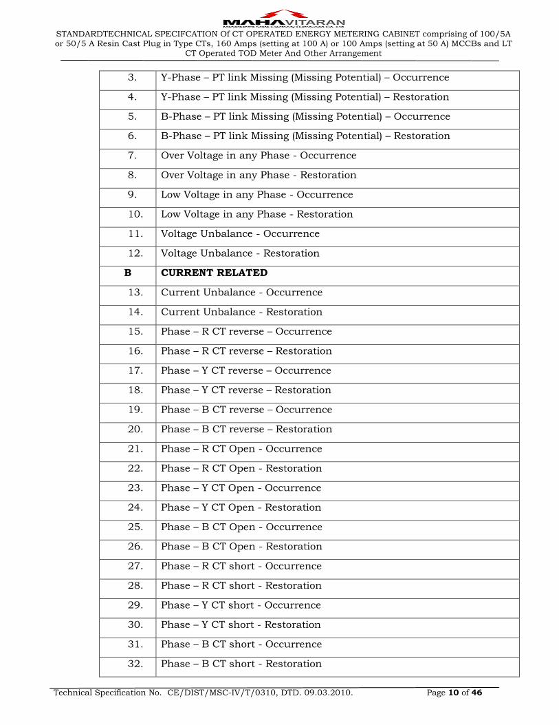
The tampers detailed above are tabulated as below.
SR. NO. DESCRIPTION OF TAMPERS
A VOLTAGE RELATED
1. R-Phase – PT link Missing (Missing Potential) – Occurrence
2. R-Phase – PT link Missing (Missing Potential) – Restoration
STANDARDTECHNICAL SPECIFCATION Of CT OPERATED ENERGY METERING CABINET comprising of 100/5A or 50/5 A Resin Cast Plug in Type CTs, 160 Amps (setting at 100 A) or 100 Amps (setting at 50 A) MCCBs and LT
CT Operated TOD Meter And Other Arrangement
Technical Specification No. CE/DIST/MSC-IV/T/0310, DTD. 09.03.2010. Page 10 of 46
3. Y-Phase – PT link Missing (Missing Potential) – Occurrence
4. Y-Phase – PT link Missing (Missing Potential) – Restoration
5. B-Phase – PT link Missing (Missing Potential) – Occurrence
6. B-Phase – PT link Missing (Missing Potential) – Restoration
7. Over Voltage in any Phase - Occurrence
8. Over Voltage in any Phase - Restoration
9. Low Voltage in any Phase - Occurrence
10. Low Voltage in any Phase - Restoration
11. Voltage Unbalance - Occurrence
12. Voltage Unbalance - Restoration
B CURRENT RELATED
13. Current Unbalance - Occurrence
14. Current Unbalance - Restoration
15. Phase – R CT reverse – Occurrence
16. Phase – R CT reverse – Restoration
17. Phase – Y CT reverse – Occurrence
18. Phase – Y CT reverse – Restoration
19. Phase – B CT reverse – Occurrence
20. Phase – B CT reverse – Restoration
21. Phase – R CT Open - Occurrence
22. Phase – R CT Open - Restoration
23. Phase – Y CT Open - Occurrence
24. Phase – Y CT Open - Restoration
25. Phase – B CT Open - Occurrence
26. Phase – B CT Open - Restoration
27. Phase – R CT short - Occurrence
28. Phase – R CT short - Restoration
29. Phase – Y CT short - Occurrence
30. Phase – Y CT short - Restoration
31. Phase – B CT short - Occurrence
32. Phase – B CT short - Restoration

STANDARDTECHNICAL SPECIFCATION Of CT OPERATED ENERGY METERING CABINET comprising of 100/5A or 50/5 A Resin Cast Plug in Type CTs, 160 Amps (setting at 100 A) or 100 Amps (setting at 50 A) MCCBs and LT
CT Operated TOD Meter And Other Arrangement
Technical Specification No. CE/DIST/MSC-IV/T/0310, DTD. 09.03.2010. Page 11 of 46
33. CT Bypass – Occurrence
34. CT Bypass – Restoration
35. Over Current in any Phase – Occurrence
36. Over Current in any Phase – Restoration
C POWER RELATED
37. Power failure – Occurrence
38. Power failure – Restoration
D TRANSACTION RELATED
39. TOU Programming
40. Tamper resetting
41. Manual MD reset
42. Demand integration period change
43. Display change
44. RTC Programming / Change
45. Firmware upgrade
46. Modification of internal ct/pt ratio (even by manufacturer’s proprietary
47. Software
E OTHERS
48. Influence of permanent magnet or AC/ DC electromagnet - Occurrence
49. Influence of permanent magnet or AC/ DC electromagnet - Restoration
50. Neutral Disturbance - HF & DC - Occurance
51. Neutral Disturbance - HF & DC - Restoration
52. Very Low PF
F CONTROL EVENTS
53. Meter disconnected
54. Meter connected
6.11 DISPLAYS
The meter shall have 7 digits (with ± indication), parameter identifier, backlit
Liquid Crystal Display (LCD) of minimum 10 mm height and wide viewing angle.
The meter display of 8 digits shall also be preferred. The decimal units shall not
be displayed. Except for high resolution, the auto display cycling push button is
required with persistence time of 10 Seconds. LCD shall be suitable for
STANDARDTECHNICAL SPECIFCATION Of CT OPERATED ENERGY METERING CABINET comprising of 100/5A or 50/5 A Resin Cast Plug in Type CTs, 160 Amps (setting at 100 A) or 100 Amps (setting at 50 A) MCCBs and LT
CT Operated TOD Meter And Other Arrangement
Technical Specification No. CE/DIST/MSC-IV/T/0310, DTD. 09.03.2010. Page 12 of 46
temperature withstand of 700 C. The adequate back up arrangement for storing of
energy registered at the time of power interruption shall be provided.
The meters shall be pre-programmed for following details. Display other than
specified below shall be blocked.
a) P. T. Ratio: 415 V
b) C.T. Ratio: 50 / 5 Amps or 100 / 5 Amps as per requirement
c) M.D. resetting shall be manual as per clause no. 6.07 (i) & (ii)
d) MD Integration Period is 30 Minutes.
e) Average power factor with 2 decimal digits shall be displayed.
f) Tamper data shall be stored in memory and retrieved by HHU, CMRI or Laptop
with necessary software.
g) It shall be possible to upload the HHU / CMRI data to any PC having HHU /
CMRI software. A consumer based data uploading facility is required so that
HHU / CMRI shall upload data only in that PC which has the concerned
consumers` data, the consumer code + meter No. Shall be the key for creating
consumers` files or overwriting consumers` files in PC. The software system files
and data files shall be stored in different directories.
h) The “record number field shall be 10 digits Alphanumeric. (2digits for Zones, 2
for Circle & 6 for Transformer Centre No.) Before accepting the data for “Record
Number” the system shall wait for pressing of “Enter” key.
i) Two separate fields shall be provided for consumer name and address – one
name field of one line, and other Address field of two lines.
j) The meter shall measure & record total energy (Active + Reactive) consisting of
energy due to harmonics.
6.12 QUANTITIES TO BE MEASURED & DISPLAYED
6.12.01 The meter shall be capable of displaying automatically in the following sequence.
I. Normal mode (with scrolling time 9 sec)
(a) LCD Test
(b) Date and time
(c) Cumulative kWh
(d) Cumulative kWh TOD
(e) Current month MD kVA
(f) Current month MD kVA TOD
(g) Previous month MD kVA TOD
(h) Cumulative kVAh
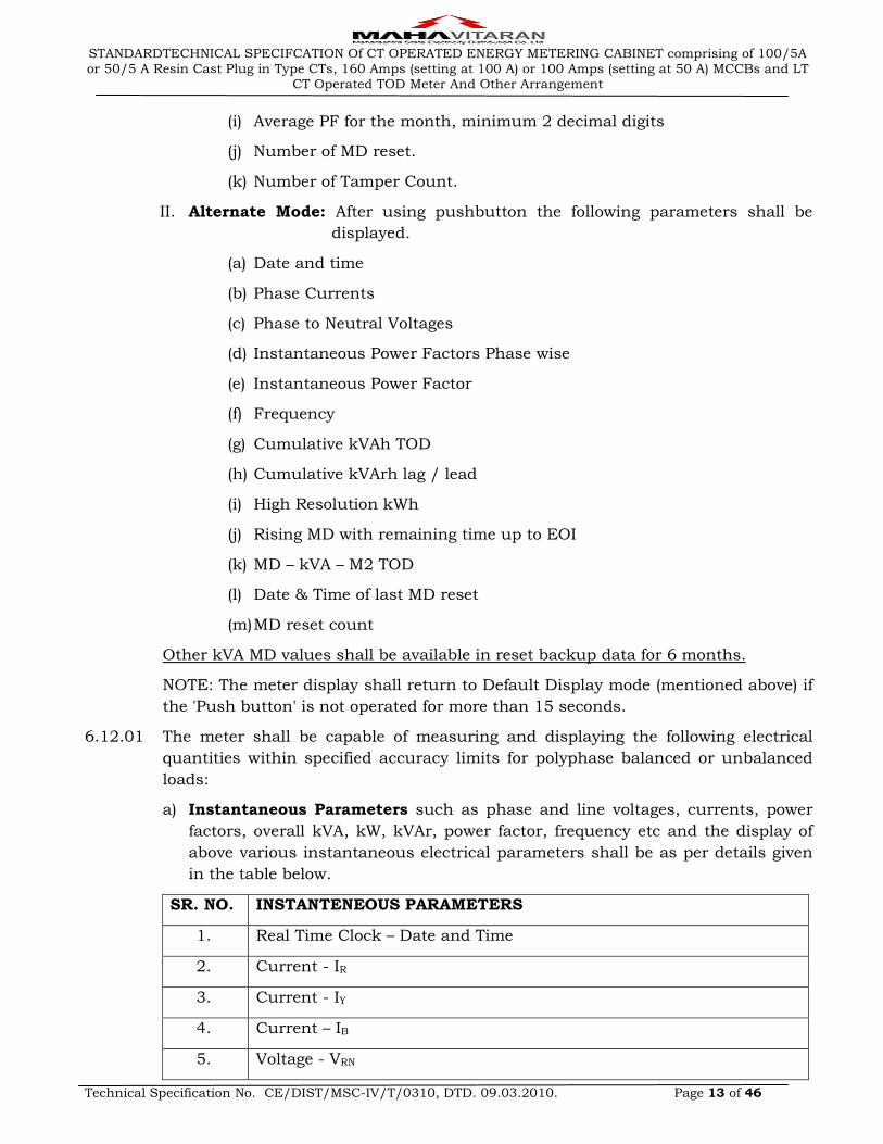
STANDARDTECHNICAL SPECIFCATION Of CT OPERATED ENERGY METERING CABINET comprising of 100/5A or 50/5 A Resin Cast Plug in Type CTs, 160 Amps (setting at 100 A) or 100 Amps (setting at 50 A) MCCBs and LT
CT Operated TOD Meter And Other Arrangement
Technical Specification No. CE/DIST/MSC-IV/T/0310, DTD. 09.03.2010. Page 13 of 46
(i) Average PF for the month, minimum 2 decimal digits
(j) Number of MD reset.
(k) Number of Tamper Count.
II. Alternate Mode: After using pushbutton the following parameters shall be
displayed.
(a) Date and time
(b) Phase Currents
(c) Phase to Neutral Voltages
(d) Instantaneous Power Factors Phase wise
(e) Instantaneous Power Factor
(f) Frequency
(g) Cumulative kVAh TOD
(h) Cumulative kVArh lag / lead
(i) High Resolution kWh
(j) Rising MD with remaining time up to EOI
(k) MD – kVA – M2 TOD
(l) Date & Time of last MD reset
(m) MD reset count
Other kVA MD values shall be available in reset backup data for 6 months.
NOTE: The meter display shall return to Default Display mode (mentioned above) if
the 'Push button' is not operated for more than 15 seconds.
6.12.01 The meter shall be capable of measuring and displaying the following electrical
quantities within specified accuracy limits for polyphase balanced or unbalanced
loads:
a) Instantaneous Parameters such as phase and line voltages, currents, power
factors, overall kVA, kW, kVAr, power factor, frequency etc and the display of
above various instantaneous electrical parameters shall be as per details given
in the table below.
SR. NO. INSTANTENEOUS PARAMETERS
1. Real Time Clock – Date and Time
2. Current - IR
3. Current - IY
4. Current – IB
5. Voltage - VRN
STANDARDTECHNICAL SPECIFCATION Of CT OPERATED ENERGY METERING CABINET comprising of 100/5A or 50/5 A Resin Cast Plug in Type CTs, 160 Amps (setting at 100 A) or 100 Amps (setting at 50 A) MCCBs and LT
CT Operated TOD Meter And Other Arrangement
Technical Specification No. CE/DIST/MSC-IV/T/0310, DTD. 09.03.2010. Page 14 of 46
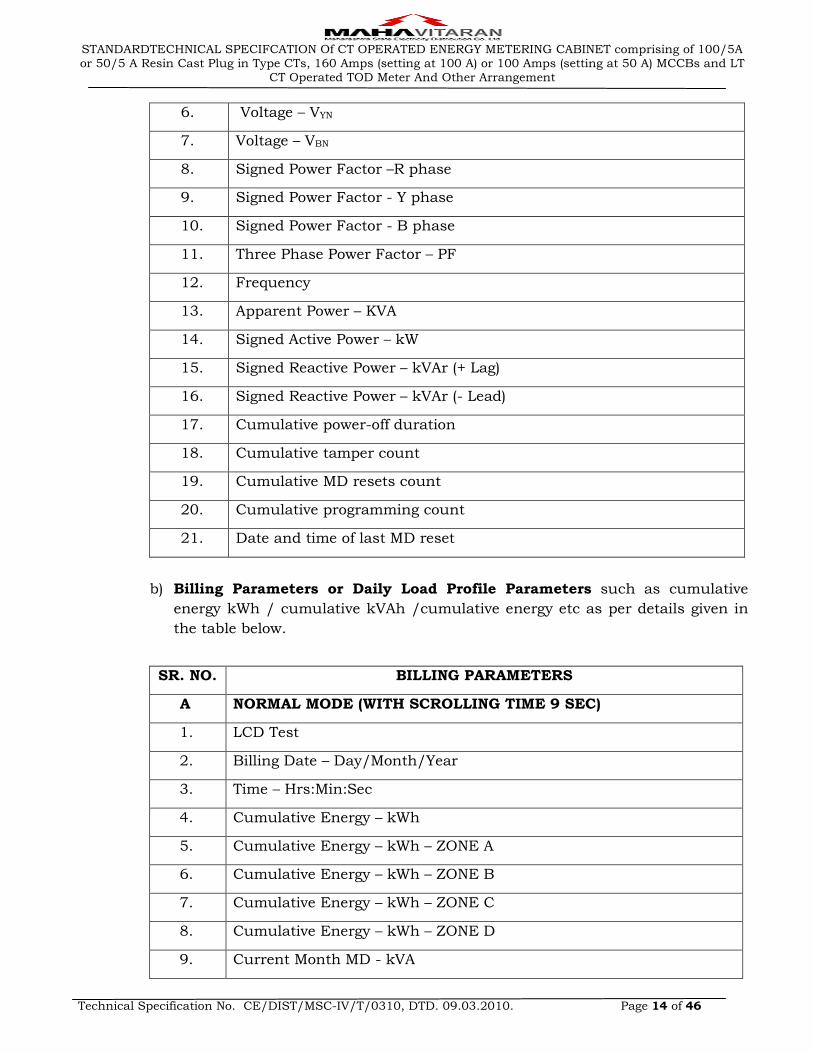
6. Voltage – VYN
7. Voltage – VBN
8. Signed Power Factor –R phase
9. Signed Power Factor - Y phase
10. Signed Power Factor - B phase
11. Three Phase Power Factor – PF
12. Frequency
13. Apparent Power – KVA
14. Signed Active Power – kW
15. Signed Reactive Power – kVAr (+ Lag)
16. Signed Reactive Power – kVAr (- Lead)
17. Cumulative power-off duration
18. Cumulative tamper count
19. Cumulative MD resets count
20. Cumulative programming count
21. Date and time of last MD reset
b) Billing Parameters or Daily Load Profile Parameters such as cumulative
energy kWh / cumulative kVAh /cumulative energy etc as per details given in
the table below.
SR. NO. BILLING PARAMETERS
A NORMAL MODE (WITH SCROLLING TIME 9 SEC)
1. LCD Test
2. Billing Date – Day/Month/Year
3. Time – Hrs:Min:Sec
4. Cumulative Energy – kWh
5. Cumulative Energy – kWh – ZONE A
6. Cumulative Energy – kWh – ZONE B
7. Cumulative Energy – kWh – ZONE C
8. Cumulative Energy – kWh – ZONE D
9. Current Month MD - kVA
STANDARDTECHNICAL SPECIFCATION Of CT OPERATED ENERGY METERING CABINET comprising of 100/5A or 50/5 A Resin Cast Plug in Type CTs, 160 Amps (setting at 100 A) or 100 Amps (setting at 50 A) MCCBs and LT
CT Operated TOD Meter And Other Arrangement
Technical Specification No. CE/DIST/MSC-IV/T/0310, DTD. 09.03.2010. Page 15 of 46
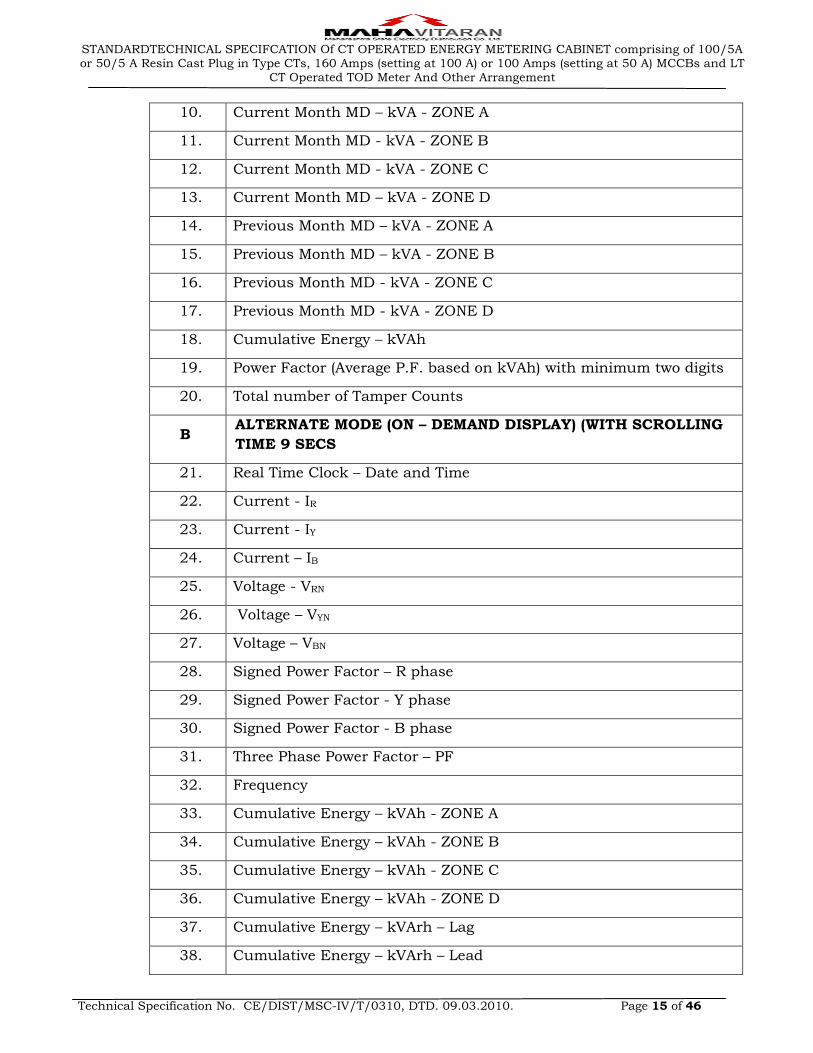
10. Current Month MD – kVA - ZONE A
11. Current Month MD - kVA - ZONE B
12. Current Month MD - kVA - ZONE C
13. Current Month MD – kVA - ZONE D
14. Previous Month MD – kVA - ZONE A
15. Previous Month MD – kVA - ZONE B
16. Previous Month MD - kVA - ZONE C
17. Previous Month MD - kVA - ZONE D
18. Cumulative Energy – kVAh
19. Power Factor (Average P.F. based on kVAh) with minimum two digits
20. Total number of Tamper Counts
B ALTERNATE MODE (ON – DEMAND DISPLAY) (WITH SCROLLING
TIME 9 SECS
21. Real Time Clock – Date and Time
22. Current - IR
23. Current - IY
24. Current – IB
25. Voltage - VRN
26. Voltage – VYN
27. Voltage – VBN
28. Signed Power Factor – R phase
29. Signed Power Factor - Y phase
30. Signed Power Factor - B phase
31. Three Phase Power Factor – PF
32. Frequency
33. Cumulative Energy – kVAh - ZONE A
34. Cumulative Energy – kVAh - ZONE B
35. Cumulative Energy – kVAh - ZONE C
36. Cumulative Energy – kVAh - ZONE D
37. Cumulative Energy – kVArh – Lag
38. Cumulative Energy – kVArh – Lead
STANDARDTECHNICAL SPECIFCATION Of CT OPERATED ENERGY METERING CABINET comprising of 100/5A or 50/5 A Resin Cast Plug in Type CTs, 160 Amps (setting at 100 A) or 100 Amps (setting at 50 A) MCCBs and LT
CT Operated TOD Meter And Other Arrangement
Technical Specification No. CE/DIST/MSC-IV/T/0310, DTD. 09.03.2010. Page 16 of 46
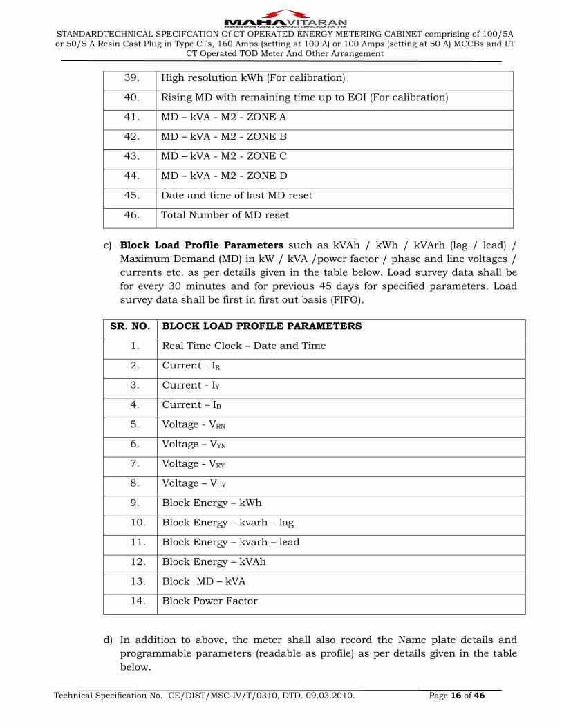
39. High resolution kWh (For calibration)
40. Rising MD with remaining time up to EOI (For calibration)
41. MD – kVA - M2 - ZONE A
42. MD – kVA - M2 - ZONE B
43. MD – kVA - M2 - ZONE C
44. MD – kVA - M2 - ZONE D
45. Date and time of last MD reset
46. Total Number of MD reset
c) Block Load Profile Parameters such as kVAh / kWh / kVArh (lag / lead) /
Maximum Demand (MD) in kW / kVA /power factor / phase and line voltages /
currents etc. as per details given in the table below. Load survey data shall be
for every 30 minutes and for previous 45 days for specified parameters. Load
survey data shall be first in first out basis (FIFO).
SR. NO. BLOCK LOAD PROFILE PARAMETERS
1. Real Time Clock – Date and Time
2. Current - IR
3. Current - IY
4. Current – IB
5. Voltage - VRN
6. Voltage – VYN
7. Voltage - VRY
8. Voltage – VBY
9. Block Energy – kWh
10. Block Energy – kvarh – lag
11. Block Energy – kvarh – lead
12. Block Energy – kVAh
13. Block MD – kVA
14. Block Power Factor
d) In addition to above, the meter shall also record the Name plate details and
programmable parameters (readable as profile) as per details given in the table
below.
STANDARDTECHNICAL SPECIFCATION Of CT OPERATED ENERGY METERING CABINET comprising of 100/5A or 50/5 A Resin Cast Plug in Type CTs, 160 Amps (setting at 100 A) or 100 Amps (setting at 50 A) MCCBs and LT
CT Operated TOD Meter And Other Arrangement
Technical Specification No. CE/DIST/MSC-IV/T/0310, DTD. 09.03.2010. Page 17 of 46
SR.NO. PARAMETERS
A NAME PLATE DETAILS
1. Meter Serial Number
2. Manufacturer name
3. Firmware Version for meter
4. Internal CT ratio
5. Internal PT ratio
6. Meter year of manufacture
B PROGRAMMABLE PARAMETERS
7. Real Time Clock – Date and Time
8. Demand Integration Period
9. Profile Capture Period
10. Single-action Schedule for Billing Dates
11. Activity Calendar for Time Zones etc.
12. Time Zones script table
6.13 PERFORMANCE UNDER INFLUENCE QUANTITIES
The meters performance under influence quantities shall be governed by IS: 14697
- 1999 (reaffirmed 2004) and CBIP - 88. The accuracy of meter shall not exceed the
permissible limits of accuracy as per standard IS: 14697 (latest version).
6.14 OUTPUT DEVICE
Energy Meter shall have test output, accessible from the front, and be capable of
being monitored with suitable testing equipment while in operation at site. The
operation indicator must be visible from the front and test output device shall be
provided in the form of LED. Resolution of the test output device shall be
sufficient to enable the starting current test in less than 10 minutes.
6.15 TESTS
6.15.01 Type Tests
The meter offered shall have successfully passed all type tests described in the
IS: 14697. The Type test certificate shall be submitted at the time of submission of
bid. Make & type of major components used in the type-tested meter shall be
indicated in the QAP.
All the Type Tests specified in the technical specifications and as per IS: 14697
shall be carried out at laboratories which are accredited by the National Board of
Testing and Calibration Laboratories (NABL) of Govt. of India such as CPRI
Bangalore / Bhopal, ERDA Baroda, ERTL. Type Test Reports conducted in
STANDARDTECHNICAL SPECIFCATION Of CT OPERATED ENERGY METERING CABINET comprising of 100/5A or 50/5 A Resin Cast Plug in Type CTs, 160 Amps (setting at 100 A) or 100 Amps (setting at 50 A) MCCBs and LT
CT Operated TOD Meter And Other Arrangement
Technical Specification No. CE/DIST/MSC-IV/T/0310, DTD. 09.03.2010. Page 18 of 46
manufacturers own laboratory and certified by testing institute shall not be
acceptable.
The type test reports shall clearly indicate the constructional features of the type
tested meters. The type test reports for each offered type of meters shall be
submitted separately
Further purchaser shall reserve the right to pick up energy meters at random from
the lots offered and get the meter tested at third party lab i.e. CPRI / agencies
listed at Appendix-C of Latest – standardization of AC static electrical energy
meters – CBIP publication No. – 304 / NPL / CQAL / ERTL / ERDA at the sole
discretion of the Purchaser. The supplier has no right to contest the test results of
the third party lab or for additional test and has to replace / take corrective action
at the cost of the supplier.
It shall be the responsibility of the supplier to arrange such tests and Purchaser
shall be informed of the date and time of conduction of tests well in advance to
enable him to witness such tests. Test charges of the testing authority, for such
successful repeat type tests, shall be reimbursed at actual by the Purchaser.
6.15.02 Acceptance & Routine Tests
i) Criteria for selection for such tests and performance requirements shall be as
per IS: 14697 - 1999 (reaffirmed 2004). Thus all acceptance tests as per IS:
14697 / 1999 shall be carried out on the meters.
ii) Accuracy tests shall be performed at the beginning and at the end of the
acceptance tests specified.
iii) All routine tests as per IS: 14697/1999 shall be carried out on all the meters.
iv) Likewise all routine tests as per IS: 11731 shall be carried out on meter base &
cover.
6.15.03 Transportation Test
At least 50% of the samples of the meters shall be tested for error at Imax, Ib and
5% Ib at unity power factor and 50% Imax and 10% Ib at 0.5 lagging Power Factor
besides checking them for starting current. This test shall be conducted on ready
to install meter i.e. meter cover ultrasonically welded & sealed. After recording
these errors, the meters be put in their normal packing and transported for at least
50 km in any transport vehicle such as pick up van, Jeep, etc. on uneven rural
roads and then re-tested at all these loads after the transportation. The variation in
errors recorded before and after transportation shall not exceed 1% at higher loads
and 1.5% at loads below Ib.
6.15.04 Other Acceptance Tests
Additional acceptance tests shall include the following.
i) The meter shall withstand continuously for a period of at least 5 minutes at a
voltage of 440 V between phase and neutral without damage / problems.
STANDARDTECHNICAL SPECIFCATION Of CT OPERATED ENERGY METERING CABINET comprising of 100/5A or 50/5 A Resin Cast Plug in Type CTs, 160 Amps (setting at 100 A) or 100 Amps (setting at 50 A) MCCBs and LT
CT Operated TOD Meter And Other Arrangement
Technical Specification No. CE/DIST/MSC-IV/T/0310, DTD. 09.03.2010. Page 19 of 46
ii) Meters shall be tested for tamper conditions as stated in this specification.
iii) Glow wire testing for polycarbonate body.
iv) Power consumption tests shall be carried out.
v) Surge withstand (SWC) for 6 kVp, Lightning impulse test and HF disturbance
test as per IS 14697. One sample meter per order from one of the offered lot
shall be subjected to these specific tests. Meters subjected to these tests shall
not be used after tests.
vi) All acceptance tests as per IS: 11731 (FH-1 category) shall be carried out on the
meter body, heat deflection test as per ISO:75, glow wire test as per the
IS:11000 (part 2/SEC-1) 1984 OR IEC PUB 60695-2-12, Ball pressure test as
per IEC--60695-10-2 and Flammability Test as per UL 94 or as per IS
11731(Part-2) 1986.
vii) The meter shall comply all the tests for external AC / DC / Permanent magnetic
field as per CBIP Tech Report 88 with latest amendments. If the accuracy of
meter gets affected under influence of any abnormal magnetic field, then the
same shall be recorded as magnetic tamper event with date & time stamping
and the meter shall record energy considering Imax and reference voltage at
unity power factor in all the three phases. Moreover, the magnetic influence test
for permanent magnet of 0.5 T for minimum period of 15 minutes shall be
carried out by putting the magnet on the meter body. If the accuracy of the
meter gets affected during the test, then the same shall be recorded as magnetic
tamper event with date & time stamping and the meter shall record energy
considering Imax and reference voltage at unity power factor in all the three
phases. After removal of magnet, meter shall be subjected to accuracy test as
per IS 13779 / 1999 (amended up to date). No deviation in error is allowed in
the accuracy as per specifications.
viii) The meter shall withstand impulse voltage at 10 kV.
The tests 6.15.4, (i) to (vi) shall be carried out at factory for each inspected lot at
the time of pre dispatch inspection.
The tests 6.15.4 (vii) & (viii) shall be carried out on one sample from first lot as per
procedure laid down in IS: 14697/1999 (amended up to date), CBIP Tech-Report
88 (with latest amendments) & IS: 11731 (FH-1 category) in NABL LAB. All these
test reports shall be got approved from Chief Engineer (Dist.) before
commencement of supply.
6.15.05 For influence quantities like, voltage variation, frequency variation, voltage
unbalance etc. the limits of variation in percentage error shall be as per IS: 14697
/ 1999 (amended up to date).
6.16 CONNECTION DIAGRAM AND TERMINAL MARKINGS
The connection diagram of the meter shall be clearly shown on inside portion of the
terminal cover and shall be of permanent nature. Meter terminals shall also be

STANDARDTECHNICAL SPECIFCATION Of CT OPERATED ENERGY METERING CABINET comprising of 100/5A or 50/5 A Resin Cast Plug in Type CTs, 160 Amps (setting at 100 A) or 100 Amps (setting at 50 A) MCCBs and LT
CT Operated TOD Meter And Other Arrangement
Technical Specification No. CE/DIST/MSC-IV/T/0310, DTD. 09.03.2010. Page 20 of 46
marked and this marking shall appear in the above diagram. The diagram &
terminal marking on sticker shall not be allowed.
6.17 MANUFACTURING PROCESS, ASSEMBLY AND TESTING
Meters shall be manufactured using latest and ‘state of the art’ technology and
methods prevalent in electronics industry. The meter shall be made from high
accuracy and reliable surface mount technology (SMT) components. All inward flow
of major components and sub assembly parts (CT, PT, RTCs / Crystal, LCDs,
LEDs, power circuit electronic components etc.) shall have batch and source
identification. Multilayer ‘PCB’ assembly with ‘PTH’ (Plated through Hole) using
surface mounted component shall have adequate track clearance for power
circuits. SMT component shall be assembled using automatic ‘pick-and-place’
machines, Reflow Soldering oven, for stabilized setting of the components on ‘PCB’.
For soldered PCBs, cleaning and washing of cards, after wave soldering process is
to be carried out as a standard practice. Assembly line of the manufacturing
system shall have provision for testing of sub-assembled cards. Manual placing of
components and soldering, to be minimized to items, which cannot be handled by
automatic machine. Handling of ‘PCB’ with ICs / C-MOS components, to be
restricted to bare minimum and precautions to prevent ‘ESD’ failure to be
provided. Complete assembled and soldered PCB shall undergo functional testing
using computerized Automatic Test Equipment.
Test points shall be provided to check the performance of each block / stage of the
meter circuitry. RTC shall be synchronized with NPL time at the time of
manufacture. Meters testing at intermediate and final stage shall be carried out
with testing instruments, duly calibrated with reference standard, with traceability
of source and date.
A) MANUFACTURING ACTIVITIES
a) Prior to final testing and calibration, all meters shall be subjected to aging test
(i.e. Meters shall be kept in ovens for 72 hours at 55 0C temperature and
atmospheric humidity under real life condition at its full load current. After 72
hours meters shall work satisfactory to eliminate infant mortality.
b) The calibration of meters shall be done in-house.
c) The bidders shall submit the list of all imported & indigenous components
separately used in meter along with the offer.
d) Bought out items: A detailed list of bought out items which are used in the
manufacture of the meter shall be furnished indicating the name of firms
from whom these items are procured. The bidder shall also give the details of
quality assurance procedures followed by him in respect of the bought out
items.
e) List of Plant and Machinery:
STANDARDTECHNICAL SPECIFCATION Of CT OPERATED ENERGY METERING CABINET comprising of 100/5A or 50/5 A Resin Cast Plug in Type CTs, 160 Amps (setting at 100 A) or 100 Amps (setting at 50 A) MCCBs and LT
CT Operated TOD Meter And Other Arrangement
Technical Specification No. CE/DIST/MSC-IV/T/0310, DTD. 09.03.2010. Page 21 of 46
SN List of Plant and Machinery used for Energy meter Production
1 Fully automatic testing Bench with ICT for testing link less meters
Routine Testing and Calibration of Meters
2 Semi automatic testing Bench with MSVT
Routine Testing and Calibration of Meters
3 IR Tester Insulation testing
4 HV Tester Insulation testing
5 Error calculators Error testing
6 Long duration Running test set ups Reliability Testing
7 Reference Meters Class 0.01 accuracy
Error calculation
8 Ultrasonic welding Machines Welding of meters
9 Automatic Pick and Place Machines Automatic placing of SMT components
10 Solder Paste Printing Machine SMT soldering
11 Soldering Furnace IR reflow SMT soldering
12 PCB Scanner For testing of PCBs
13 ATE functional tester For testing of Components
14 Programmers and Program Loaders Chip Programming Tools
15 CAD PCB designing setups PCB designing
16 Furnace IR type for Hybrid Micro Circuits
Resistance network and HMC manufacturing
17 Laser Trimming Machines Trimming of resistances for higher accuracy measurement
18 Wave Soldering Machines Wave soldering of PCBs
19 Humidity Chamber Accelerated testing for Life cycle
20 Dry Heat Test Chamber Accelerated testing for Life cycle
21 Thermal Shock Chamber Accelerated testing for Life cycle
22 PRO -E Mechanical Design Stations Mechanical CAD stations
23 Spark Erosion Tool fabricating Machine
Tool fabrication and Die manufacturing
24 CNC wire Cut Tool Fabrication machine
Tool fabrication and Die manufacturing
25 CNC Milling Machine for composite tool fabrication
Tool fabrication and Die manufacturing
26 Injection Moulding Machine Moulding of plastic parts
27 Vibration testing Machine Vibration testing of Meters
STANDARDTECHNICAL SPECIFCATION Of CT OPERATED ENERGY METERING CABINET comprising of 100/5A or 50/5 A Resin Cast Plug in Type CTs, 160 Amps (setting at 100 A) or 100 Amps (setting at 50 A) MCCBs and LT
CT Operated TOD Meter And Other Arrangement
Technical Specification No. CE/DIST/MSC-IV/T/0310, DTD. 09.03.2010. Page 22 of 46
28 Glow Wire Test machine Testing of Plastic Material
29 Fast transient burst testing setup Type testing of Meters
30 Short term over Current testing setup
Type testing of Meters
31 Magnetic and other tamper testing setups
Tamper Testing
32 Impulse Voltage Testing Setup Type testing of Meters
33 Composite Environmental testing chambers
Type testing of Meters
B) MINIMUM TESTING FACILITIES
Manufacturer shall posses fully automatic computerized Meter Test Bench System
having inbuilt source and load adjustment for carrying out routine and acceptance
Tests as per IEC: 687 or CBIP-88. In addition this facility shall produce Test
Reports for each and every Meter. The tenderer shall have the necessary minimum
testing facilities for carrying out the following tests.
Sr. No. Name of Test
1 A.C. Voltage test
2 Insulation Resistance Test
3 Test on limits of errors
4 Test on meter constant
5 Test of starting condition
6 Test of no-load condition
7 Repeatability of error test
8 Test of power Consumption
9 Vibration test
10 Shock Test
11 Tamper conditions - as per MSEDCL, specification
12 The manufacturer shall have duly calibrated RSS meter of class 0.1 accuracy
6.18 COMPONENT SELECTION: As per Annexure I enclosed.
STANDARDTECHNICAL SPECIFCATION Of CT OPERATED ENERGY METERING CABINET comprising of 100/5A or 50/5 A Resin Cast Plug in Type CTs, 160 Amps (setting at 100 A) or 100 Amps (setting at 50 A) MCCBs and LT
CT Operated TOD Meter And Other Arrangement
Technical Specification No. CE/DIST/MSC-IV/T/0310, DTD. 09.03.2010. Page 23 of 46
ANNEXURE I
Sr.
No.
Component
function Requirement Makes and Origin
1. Current
Transformers
The Meters shall be with the
current transformers as
measuring elements.
The current transformer shall
withstand for the clauses under
5 & 9 of IS -14697/1999.
The current transformer
shall withstand for the
clauses under5&9 of
IS-14697/1999
2.
Measurement
or computing
chips
The measurement or computing
chips used in the Meter shall be
with the Surface mount type
along with the ASICs.
USA: Analog Devices,
Cyrus Logic, Atmel,
Philips
South Africa: SAMES
Japan: NEC
3. Memory chips
The memory chips shall not be
affected by external parameters
like sparking, high voltage spikes
or electrostatic discharges.
USA: Atmel, National
Semiconductors, Texas
Instruments, Philips,
ST,
Japan: Hitachi
4. Display
modules
a) The display modules shall be
well protected from the external
UV radiations.
b) The display visibility shall be
sufficient to read the Meter
mounted at height of 0.5 meter
as well as at the height of 2
meters (refer 3.2 d for viewing
angle).
c) The construction of the
modules shall be such that the
displayed quantity shall not be
disturbed with the life of display
(PIN Type).
d) It shall be trans-reflective HTN
or STN type industrial grade
with extended temperature
range.
Hong Kong: Genda
Singapore: Bonafied
Technologies.
Korea: Advantek
China: Success
Japan: Hitachi, Sony.
5. Communication
Modules
Communication modules shall be
compatible for the two ports (one
USA: National
Semiconductors, HP,
STANDARDTECHNICAL SPECIFCATION Of CT OPERATED ENERGY METERING CABINET comprising of 100/5A or 50/5 A Resin Cast Plug in Type CTs, 160 Amps (setting at 100 A) or 100 Amps (setting at 50 A) MCCBs and LT
CT Operated TOD Meter And Other Arrangement
Technical Specification No. CE/DIST/MSC-IV/T/0310, DTD. 09.03.2010. Page 24 of 46
optical port for communication
with meter reading instruments
& the other hardwired RS 232
port to communicate with
various modems for AMR)
Optonica
Holland/Korea: Phillips
Japan: Hitachi
Taiwan: Ligitek
6. Optical port
Optical port shall be used to
transfer the meter data to meter
reading instrument.
The mechanical construction of
the port shall be such as to
facilitate the data transfer easily.
USA: National
Semiconductors, HP,
Holland/Korea: Phillips
Japan: Hitachi
Taiwan: Ligitek
7. Power supply
The power supply shall be with
the Capabilities as per the
relevant standards. The power
supply unit of the meter shall not
be affected in case the maximum
voltage of the system appears to
the terminals due to faults or due
to wrong connections
SMPS Type
8. Electronic
components
The active & passive components
shall be of the surface mount
type & are to be handled &
soldered by the state of art
assembly processes.
USA: National
Semiconductors, Atmel,
Philips, Texas
Instruments
Japan: Hitachi, Oki,
AVZ or Ricon
Korea: Samsung
9. Mechanical
parts
a) The internal electrical
components shall be of
electrolytic copper & shall be
protected from corrosion, rust
etc.
b) The other mechanical
components shall be protected
from rust, corrosion etc. by
suitable plating / painting
methods.
10. Battery Chargeable maintenance free
guaranteed life of 10 years.
Varta, Tedirun, Sanyo
or National.
11. RTC & Micro
controller.
The accuracy of RTC shall be as
per relevant IEC / IS standards.
USA: Philips, Dallas
Atmel, Motorola,
STANDARDTECHNICAL SPECIFCATION Of CT OPERATED ENERGY METERING CABINET comprising of 100/5A or 50/5 A Resin Cast Plug in Type CTs, 160 Amps (setting at 100 A) or 100 Amps (setting at 50 A) MCCBs and LT
CT Operated TOD Meter And Other Arrangement
Technical Specification No. CE/DIST/MSC-IV/T/0310, DTD. 09.03.2010. Page 25 of 46
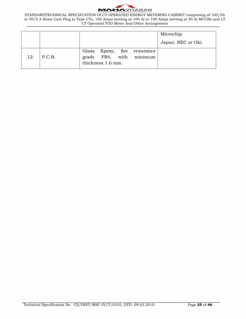
Microchip
Japan: NEC or Oki.
12. P.C.B.
Glass Epoxy, fire resistance
grade FR4, with minimum
thickness 1.6 mm.
STANDARDTECHNICAL SPECIFCATION Of CT OPERATED ENERGY METERING CABINET comprising of 100/5A or 50/5 A Resin Cast Plug in Type CTs, 160 Amps (setting at 100 A) or 100 Amps (setting at 50 A) MCCBs and LT
CT Operated TOD Meter And Other Arrangement
Technical Specification No. CE/DIST/MSC-IV/T/0310, DTD. 09.03.2010. Page 26 of 46
7.00 SPECIFICATIONS FOR CURRENT TRANSFORMERS
7.01 The Current Transformers shall be resin cast, copper wound primary type. Three
CTs with Neutral link shall be casted as one unit. The resin cast CT unit shall have
studs for CT / PT connections on which the meter shall be directly plugged in and
after plug-in of meter; the terminals shall not be visible. Only the Primary
Terminals shall be accessible for connections. The suitable studs shall be provided
for plug in arrangement. The Manufacturer of the box shall ensure the plugging of
CT with meters used by them.
7.02 The current density of current carrying parts shall not exceed 1.6 A/mm2; the
primary terminals shall be suitable for double the rated current. C.T. shall confirm
to IS: 2705/1992 (Amended up to date) or its latest version. C.Ts. shall have
current ratio of 50/5 Amps for 50 Amps meters and 100/5 Amps for 100 Amps
meters, and accuracy class of 0.2 S, and rated burden of 5 VA and rated short time
current of 7.5 KA for 1 sec. corresponding to rated dynamic peak current of 2.5 x
7.5 KA (peak) for both ratios with instrument security factor (ISF) less than 5. The
ratio, name of manufacturer / monogram and year of manufacturing shall be
engraved on the body of C.T. In addition, name plate of anodized aluminium
indicating the necessary details, year of manufacture etc. engraved on it shall be
provided in such a manner that the information is clearly visible after mounting.
7.03 The colour of 100/5 Amps C.T. shall be D.A. Gray and 50/5 Amps C.T. shall be
Brown. The secondary and primary terminals shall be clearly marked as S1 & S2
and P1 & P2. The incoming terminal of C.T. shall be minimum 80 mm long having
two holes and shall be on front or on bottom side for making connection.
7.04 The Tenderer shall submit the complete type test reports for offered Resin Cast CT
with plug in arrangement along with the offer, failing which offer shall be rejected.
The CTs shall be type tested within five years at the time of submission of offer. All
the type tests as per relevant IS 2705 (Part 1) / 1992 amended up to date shall be
carried out.
8.00 SPECIFICATIONS FOR MOULDED CASE CIRCUIT BREAKERS (MCCBs)
8.01 These shall be generally conforming to IS: 13947/1993 as amended upto date. The
rated uninterrupted current of MCCBs shall be 100 Amps for 50/5 Amps meter
and 160 Amp for 100/5 Amps meter with the overload releases set at 50 Amps and
100 Amps respectively.
8.02 The tenderer shall submit the complete type test reports for offered MCCB along
with offer, failing which the offer shall be rejected.
8.03 The MCCBs shall be manually independent and shall have quick make quick brake
mechanism. The detailed specification for MCCBs shall be as under.
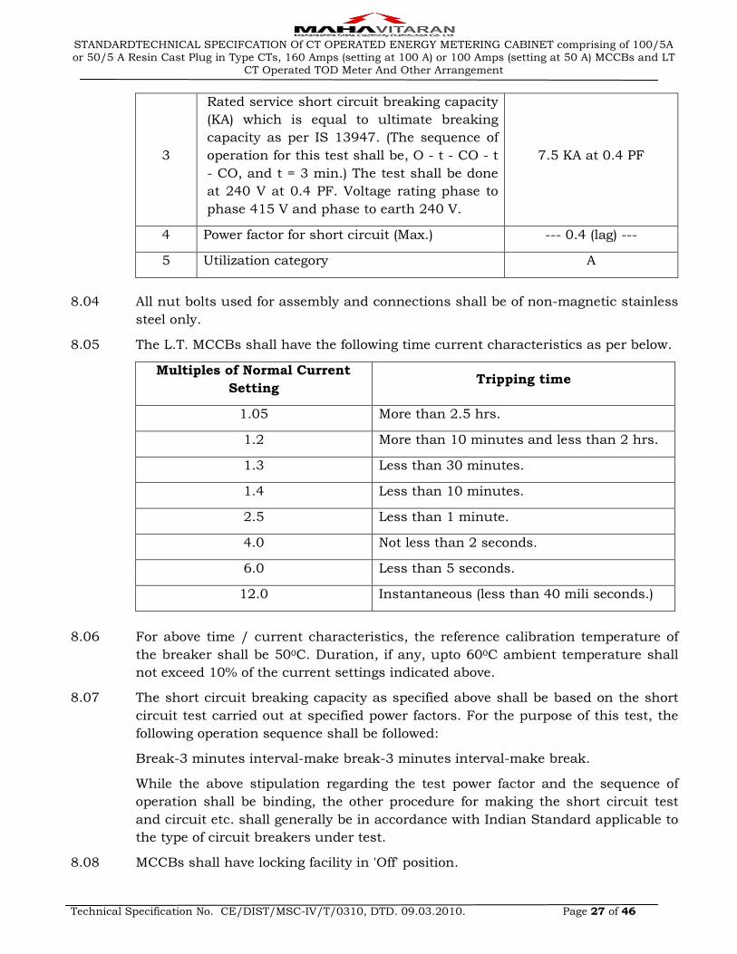
Sr. No. Rated current 100 Amps 160 Amps
1 Fixed overload release setting (AMP) 50 Amps 100 Amps
2 No. of poles 3 3
STANDARDTECHNICAL SPECIFCATION Of CT OPERATED ENERGY METERING CABINET comprising of 100/5A or 50/5 A Resin Cast Plug in Type CTs, 160 Amps (setting at 100 A) or 100 Amps (setting at 50 A) MCCBs and LT
CT Operated TOD Meter And Other Arrangement
Technical Specification No. CE/DIST/MSC-IV/T/0310, DTD. 09.03.2010. Page 27 of 46
3
Rated service short circuit breaking capacity
(KA) which is equal to ultimate breaking
capacity as per IS 13947. (The sequence of
operation for this test shall be, O - t - CO - t
- CO, and t = 3 min.) The test shall be done
at 240 V at 0.4 PF. Voltage rating phase to
phase 415 V and phase to earth 240 V.
7.5 KA at 0.4 PF
4 Power factor for short circuit (Max.) --- 0.4 (lag) ---
5 Utilization category A
8.04 All nut bolts used for assembly and connections shall be of non-magnetic stainless
steel only.
8.05 The L.T. MCCBs shall have the following time current characteristics as per below.
Multiples of Normal Current
Setting Tripping time
1.05 More than 2.5 hrs.
1.2 More than 10 minutes and less than 2 hrs.
1.3 Less than 30 minutes.
1.4 Less than 10 minutes.
2.5 Less than 1 minute.
4.0 Not less than 2 seconds.
6.0 Less than 5 seconds.
12.0 Instantaneous (less than 40 mili seconds.)
8.06 For above time / current characteristics, the reference calibration temperature of
the breaker shall be 500C. Duration, if any, upto 600C ambient temperature shall
not exceed 10% of the current settings indicated above.
8.07 The short circuit breaking capacity as specified above shall be based on the short
circuit test carried out at specified power factors. For the purpose of this test, the
following operation sequence shall be followed:
Break-3 minutes interval-make break-3 minutes interval-make break.
While the above stipulation regarding the test power factor and the sequence of
operation shall be binding, the other procedure for making the short circuit test
and circuit etc. shall generally be in accordance with Indian Standard applicable to
the type of circuit breakers under test.
8.08 MCCBs shall have locking facility in 'Off' position.
STANDARDTECHNICAL SPECIFCATION Of CT OPERATED ENERGY METERING CABINET comprising of 100/5A or 50/5 A Resin Cast Plug in Type CTs, 160 Amps (setting at 100 A) or 100 Amps (setting at 50 A) MCCBs and LT
CT Operated TOD Meter And Other Arrangement
Technical Specification No. CE/DIST/MSC-IV/T/0310, DTD. 09.03.2010. Page 28 of 46
9.00 SPECIFICATIONS FOR ENCLOSURE (METERING CABINET)
9.01 There shall be three compartments; The Meter & CT shall be housed in one
compartment and MCCB in second compartment and outgoing terminal in third
compartment. Separate sheet steel / SMC partition to isolate the three
compartments from each other shall be provided.
9.02 The compartments shall be made by using sheet Steel of 14 SWG (2 mm) thick.
Additional M.S. angle of minimum 20 x 20 x 2 mm or formed channel of 2 mm
sheet steel for supporting the Doors shall be provided in sheet steel enclosure only.
9.03 The enclosure shall be fabricated by using sheet steel and shall be properly
continuous welded from inside. Alternatively the enclosure shall be moulded out of
SMC material of S3 grade confirming to IS 13410 of not less than 14 SWG (2 mm)
thickness.
9.04 The enclosure shall comply with the requirement of IP 44 type as per IS 13947 or
the latest version thereof.
9.05 Suitable vents fitted with G. I. Double wire mesh shall be provided from inside to
ensure that the temperature inside the enclosure is not substantially different from
that of the atmosphere.
9.06 Fixing of circuit breakers inside the enclosure shall be such as to allow free
circulation of air at its back and sides.
9.07 Doors of the each chamber shall be provided with panel lock\locks. Two master
keys for opening the doors shall be provided. In addition to the panel lock,
arrangement for providing pad locks shall be made. The hinges for compartment
covers shall be as in the drawing and shall be so designed that the door cannot be
opened without breaking the seals i.e. the hinges shall be provided from inside.
9.08 The enclosure made with sheet steel shall be powder coated both from inside and
outside with suitable weather proof and corrosion resistant paints. The colour of
the inside and outside paint shall be dark admiralty gray for 100/5 Amps metering
unit and brown for 50/5 Amps metering unit. Likewise, the same colouring pattern
shall be adhered to the SMC moulded enclosure.
9.09 Necessary fixing arrangement shall be provided at the back of the enclosure. The
thickness of the fixing plate shall be minimum 5 mm.
9.10 Durable rubber gasket shall be provided around the enclosure to ensure dust and
vermin proof door construction. Rubber lining shall at least be 3 mm thick.
9.11 Roof shall be slopping down backwards with 5 degree angle.
9.12 The flats provided for fixing shall be of welded / fitted construction and the welding
shall be on all sides.
9.13 The knock out holes shall be provided on the bottom. Suitable size of brass Cable
glands shall be provided for these holes. The size of cable shall be 3½ Core 70 sq.
mm2 & 120 mm2 aluminium XLPE armoured cable.
STANDARDTECHNICAL SPECIFCATION Of CT OPERATED ENERGY METERING CABINET comprising of 100/5A or 50/5 A Resin Cast Plug in Type CTs, 160 Amps (setting at 100 A) or 100 Amps (setting at 50 A) MCCBs and LT
CT Operated TOD Meter And Other Arrangement
Technical Specification No. CE/DIST/MSC-IV/T/0310, DTD. 09.03.2010. Page 29 of 46
9.14 50 x 50 x 2 mm channel shall be welded / fitted below bottom plate so that the box
and bottom plate shall not come in direct contact with the ground while it is
stored.
9.15 Sealing arrangement shall be provided for Meter, CT & MCCB chamber separately.
9.16 Inter connecting cable for connection from C.T. to MCCB & to outgoing terminal
block shall be single core multi-stranded copper cable of size 35 mm for 50 Amps
and 70 mm2 for 100 Amps cabinet. For neutral connection, a single core copper
multi stranded cable of size 35 mm2 & 50 mm2 for 50 Amps & 100 Amps cabinets
respectively shall be used.
9.17 The Danger Board as per MSEDCL drawing no. 62.70, 2/2 and confirming to
IS: 2551 / 1982 shall be fitted / moulded on the boxes.
9.18 The lugs suitable for single core multi stranded copper cables of size 50 & 70 mm2
shall be used for making connections inside the cabinet. All lugs shall be made out
of tinned copper.
9.19 All holes for internal connections through which cables \ leads are supposed to
pass shall be provided with rubber reels.
9.20 Handles of 10 mm M.S rod shall be provided to all the doors separately to open and
close.
9.21 MCCB & CTs shall be mounted on metallic / SMC sheet of 2 mm thick or an angle
frame and then it shall be fitted in the enclosure. Meter shall be mounted on the
arrangement as shown in the drawing DIST/MM-IV/CTMR/2008/01 Sheet No. 3/3
enclosed.
9.22 The thickness of the outgoing terminal block of Bakelite / DMC shall be minimum
300 x 50 x 15 mm for both 100 Amps / 50 Amps cabinets. The tinned copper strip
of 25 x 6 mm and 180 mm long size shall be provided for outgoing termination of
cables. Incoming terminal of C.T. having 80 mm minimum length shall be bolted
directly on the terminal block. Fully threaded Stainless Steel bolts with 2 nuts and
washers of size shown in the drawing shall be provided for connections. Two Resin
cast Insulators shall be provided for support of each terminal block.
9.23 MCCB shall be so mounted that its operating knob / lever can be operated from
outside without opening the door. It shall also be possible to lock the MCCB in
‘OFF’ position so that it cannot be switched ‘ON’.
9.24 Toughened glass of 200 x 150 x 2 mm size for observing meter reading shall be
provided from inside the door. It shall be so fitted that in the event of breaking, it
shall be possible to replace it after opening the door.
9.25 All the wiring inside the cabinet is included in the scope of work. The internal
copper cables shall be suitably clamped inside the cabinet.
9.26 CTs shall be fixed with proper clamps using stainless steel bolts. All nuts & bolts
used in the cabinet for current carrying path shall be of Stainless Steel only.

STANDARDTECHNICAL SPECIFCATION Of CT OPERATED ENERGY METERING CABINET comprising of 100/5A or 50/5 A Resin Cast Plug in Type CTs, 160 Amps (setting at 100 A) or 100 Amps (setting at 50 A) MCCBs and LT
CT Operated TOD Meter And Other Arrangement
Technical Specification No. CE/DIST/MSC-IV/T/0310, DTD. 09.03.2010. Page 30 of 46
9.27 Finish of Cabinet: All sheet metal works shall undergo chemical / mechanical
cleaning process before powder coasting.
9.28 SAFETY ARRANGEMENTS
9.28.01 Two galvanized M.S. earthing studs of 50 mm long and 12 mm diameter shall be
provided for external earth connections. These shall be complete with plain
washers, spring washers, nuts, etc. Earthing Bolts must be welded / fitted properly
to prevent removal of the same from the box.
9.28.02 All live connections shall be insulted with durable insulation material.
9.29 TESTING AND MANUFACTURING FACILITIES
9.29.01 Testing Facilities
The Tenderer must clearly indicate the details of testing facilities available in the
works of manufacturer and whether the facilities are adequate to carry out all the
Routine and Acceptance tests. These facilities shall be available to MSEDCL
Engineers, if deputed to carry out or witness the tests in the manufacturer’s works.
The tenderer must have all in-house testing facility to carry out acceptance tests
on the Cabinet. If any test cannot be carried out in the manufacturer works, the
same shall be clearly stated. All testing equipments shall be duly calibrated in the
NABL approved laboratories.
9.29.02 Manufacturing Facilities:
The tenderer shall have following minimum manufacturing facilities in house to
prove his reliability as a manufacturer of CT Operated Energy Metering Cabinet.
a) Power operating shearing machine
b) Power operated press break
c) Power operated power presses
d) Welding machines
e) Assembling tools
If SMC enclosure is offered, the tenderer shall have the following minimum
manufacturing facilities in house to prove his reliability as a manufacturer of CT
Operated Energy Metering Cabinet.
(a) SMC material manufacturing machine
(b) Hydraulic press for hot press compression moulding
(c) Assembly lines for fabrication and fitting
The tenderer shall furnish detailed process of painting if sheet steel enclosure is
offered. In case the painting is to be carried out from outside agency, the tenderer
shall furnish the facilities available with sub-contractor.
STANDARDTECHNICAL SPECIFCATION Of CT OPERATED ENERGY METERING CABINET comprising of 100/5A or 50/5 A Resin Cast Plug in Type CTs, 160 Amps (setting at 100 A) or 100 Amps (setting at 50 A) MCCBs and LT
CT Operated TOD Meter And Other Arrangement
Technical Specification No. CE/DIST/MSC-IV/T/0310, DTD. 09.03.2010. Page 31 of 46
10.00 TESTS & TEST CERTIFICATES
10.01 TESTS
The type test reports for CT Operated Metering Cabinet as given below shall be
furnished with certified drawings to prove that equipment offered meets the
requirement of the specification.
(a) Temperature rise test on complete unit at rated current of unit as per IS: 623 /
1993.
(b) Degree of protection for IP - 44 on complete unit as per IS: 13947 or latest
thereof.
(c) Tests as per IS: 14772 on the Enclosure
(d) Test as per IS: 13410 for Material of Construction in case SMC Enclosure is
offered.
Acceptance Tests
Following tests shall be carried out as acceptance tests in addition to Routine Tests
given below.
On Complete Unit
a) Temperature Rise Test on One sample of each rating
b) Time current characteristic for MCCB at 1.05 & 1.2 times overload release
setting current.
c) On C.T. as per relevant IS: 2705 / 1992.
d) On MCCB as per relevant IS: 13947 / 1993.
e) Test as per IS: 14772 on the Enclosure.
f) Test as per IS: 13410 for Material of Construction in case SMC Enclosure.
Routine Tests
(a) On Complete Unit
(b) Overall Dimension checking.
(c) Insulation Resistance Tests.
(d) High Voltage Test.
(e) Operation Test on MCCB.
(f) On C.T. as per relevant IS: 2705 / 1992.
(g) On MCCB as per relevant IS: 13947/1993.
(h) Test as per IS: 14772 on the Enclosure.
(i) Test as per IS: 13410 for Material of Construction in case SMC Enclosure
For MCCB, CT & Meter, required tests shall be carried out at Original Equipment
Manufacturer’s work.
The L.T. CT. Operated Metering Cabinet, consisting of Meter, MCCB, CTs, etc. and
the Meter, MCCB & CT as per the specifications shall be fully type tested in
accordance with the relevant standards and as per the MSEDCL requirement at
NABL accredited lab. The tenderer shall furnish detailed type test reports of the
tests carried out within 5 years prior to due date of opening of offer. The detailed
STANDARDTECHNICAL SPECIFCATION Of CT OPERATED ENERGY METERING CABINET comprising of 100/5A or 50/5 A Resin Cast Plug in Type CTs, 160 Amps (setting at 100 A) or 100 Amps (setting at 50 A) MCCBs and LT
CT Operated TOD Meter And Other Arrangement
Technical Specification No. CE/DIST/MSC-IV/T/0310, DTD. 09.03.2010. Page 32 of 46
type test reports are to be submitted in sealed cover duly super-scribed on it
following details along with the offer.
“Detail Type Test Report of L.T. C.T. Operated Metering Cabinet, Meter, MCCB &
CT against Tender No………………
The detailed type test reports shall be furnished with relevant oscillogram and
certified drawings of the equipment tests. The offers without type test reports shall
be rejected.
The purchaser reserves the right to demand repetition of some or all the type tests
in presence of purchaser’s representative at purchaser’s cost. All the above Type
Test shall be carried out from laboratories which are accredited by the National
Board of Testing and Calibration Laboratories (NABL) of Government of India such
as CPRI Bangalore / Bhopal, ERDA, Baroda, to prove that equipments meet the
requirement of the specification. The tenderer shall also furnish certificate from
laboratories where type tested that required test facility available in house for that
particular test. Type Test Reports conducted in manufacturers own laboratory and
certified by testing institute shall not be acceptable.
The tenderer shall also furnish the guaranteed technical particulars of C.T.
Operated Metering Cabinet, C.T. Operated Meters, MCCBs & CTs in GTP schedule.
The offer without duly filled in GTP schedule stands rejected.
11.00 QUALITY ASSURANCE
The manufacturer shall have a comprehensive quality assurance program at all
stages of manufacture for ensuring products giving reliable, trouble free
performance. Details of the bidder’s quality assurance and test set up shall be
furnished with the bid. A detailed quality assurance program shall be finalized with
the successful bidder during the award stage. Bidder shall furnish following
information along with his bid:
i) Organization structure of the manufacturer and his main sub-suppliers (PCBs,
SMT cards, CT / PT) with details of ‘QA’ setup, overall workflow;
ii) Copy of system manual showing ‘QAP’ (Quality Assurance Plan) as actually
practiced during manufacturing and final testing.
iii) List of raw materials and critical components (ASIC chip, crystal clock, memory
register Chip, transformers, optical ports etc.) with their suppliers;
iv) Stage inspection
v) of product before final testing;
vi) Procedure adopted for ‘In-situ’ testing of PCBs, after placement of surface
mounted component, for quantitative parametric variation of tolerance by self
or sub-contractor.
vii) Testing and calibration facility, date of calibration of test bench, manpower data
of bench operators;
STANDARDTECHNICAL SPECIFCATION Of CT OPERATED ENERGY METERING CABINET comprising of 100/5A or 50/5 A Resin Cast Plug in Type CTs, 160 Amps (setting at 100 A) or 100 Amps (setting at 50 A) MCCBs and LT
CT Operated TOD Meter And Other Arrangement
Technical Specification No. CE/DIST/MSC-IV/T/0310, DTD. 09.03.2010. Page 33 of 46
viii) Sample copies of test certificate of bought out components.
12.00 QUALIFYING REQUIREMENTS
12.01 The Bidder shall be a manufacturer.
12.02 LT AC, 3 Phase, 4 Wire, LT CT operated fully Static Tri-Vector Energy Meters
12.02.01 The offers from original manufacturers of L.T.A.C. Static Energy Meter shall only be
accepted.
12.02.02 The following qualifying requirement shall be fulfilled by the bidders /
Manufacturers.
(a) The bidder / manufacturer shall have turnover of Rs. 30.00 Crores during any
one of the last three financial years.
(b) The bidder / manufacturer shall have supplied minimum 5 Lakhs static meters
during the last three financial years out of which 2 Lakhs meters shall have
been supplied in immediate preceding financial year.
(c) The bidder / manufacturer shall have minimum experience of three years of
supply or manufacturing for static energy meters upto the end of the last
financial year.
12.02.03 The offers of Indian subsidiary company, whose parent company is located abroad
fulfilling the qualifying requirements, shall be considered provided the Indian
participant subsidiary company fulfils the minimum experience of three years of
supply or manufacturing of static energy meters upto the end of the last financial
year. However, the conditions of turnover of Rs. 30.00 Crores during any one of the
last three financial years and supply of minimum quantity of 5 Lakhs static energy
meters during the last three financial years out of which 2 Lakhs meters shall have
been supplied in immediate preceding financial year can be fulfilled by the parent
company located abroad on behalf of their Indian subsidiary company. The parent
company shall furnish undertaking for accepting responsibility for supplying
quality meters as per specifications and execution of the contract on behalf of its
India based subsidiary unit who has participated in the tender in Annexure U-I.
12.02.04 In case of offers of foreign bidders/manufacturers, they shall fulfill Qualifying
Requirement as per Sr. No. 12.02.01 and 12.02.02 above.
12.02.05 The offer from any one of Indian manufacturing companies which are sister
companies of the same group and with the same management having majority of
common Directors and share holders shall be considered provided they are jointly
fulfilling the Qualifying Requirements as per Sr. No. 12.02.01 & 12.02.02 above.
12.02.06 Bidder must posses the following certifications at the time of submission of the bid.
a) The meter shall bear ISI mark
b) ISO 9000
c) ISO 14000.
12.02.07 The bidder shall have all the facility in his works for design, assembly, quality
assurance, burn-in test (Fully assembled Energy Meter), testing (all routine and
STANDARDTECHNICAL SPECIFCATION Of CT OPERATED ENERGY METERING CABINET comprising of 100/5A or 50/5 A Resin Cast Plug in Type CTs, 160 Amps (setting at 100 A) or 100 Amps (setting at 50 A) MCCBs and LT
CT Operated TOD Meter And Other Arrangement
Technical Specification No. CE/DIST/MSC-IV/T/0310, DTD. 09.03.2010. Page 34 of 46
acceptance tests), automatic calibration of Energy Meter on software based test
bench, qualified team of technical and software engineers;
Notwithstanding anything stated herein under, the Purchaser reserves the right to
assess the capacity and capability of the bidder to execute the work, shall the
circumstances warrant such assessment in the overall interest of the Purchaser.
13.00 PROTOTYPE & DRAWINGS
The successful tenderer shall have to manufacturer the prototype Cabinet for each
rating as per these specifications before bulk manufacturing. The tenderer shall
intimate the readiness of prototype to the Chief Engineer (Distribution), MSEDCL,
5th floor, Prakashgad, Mumbai. The representative of the Chief Engineer
(Distribution) shall inspect the prototype on any day within 15 days from the date
of readiness intimated. The inspection report of prototype jointly signed by
manufacturer and MSEDCL representative along with the drawings shall be
submitted by the tenderer to the Chief Engineer (Distribution). The Tenderer shall
submit the final drawings in line with these specifications and the prototype to the
Chief Engineer (Distribution) for approval before bulk manufacturing. The approval
of prototype & drawings shall be the responsibility of tenderer. No extra period
shall be allowed for getting approval of prototype and drawing & this shall be
inclusive in the period of delivery schedule given by the tenderer.
14.00 GUARANTEE
Equipments supplied shall be guaranteed for a period of 66 months from the date
of supply or 60 months from the date of installation, whichever ends later. Bidders
shall guarantee to repair or replace free of cost the meters, CTs, MCCBs and meter
boxes (if supplied), which are found to be defective / inoperative at the time of
installation, or become inoperative / defective during guarantee period.
Replacements shall be effected within 1 month from the date of intimation. If the
defective equipments are not replaced / repaired within the specified period above,
the MSEDCL shall recover an equivalent amount plus 15% supervision charges
from any of the bills of the supplier.
The bidder shall extend the guarantee of 5 years. However the backup bank
guarantee provided by the bidders shall be valid for 2 years only
15.00 INSPECTION
All tests and inspection on the items like metering cabinet, CT Operated Static
Energy Meters, CTs and the MCCBs shall be made at the place of manufacturer
unless otherwise specially agreed upon by the manufacturer and the purchaser.
The manufacturer shall provide the purchaser all reasonable facilities, without any
charge to satisfy him that the material is being supplied in accordance with this
specification. Inspection of the first lot shall be carried out jointly by representative
of the Chief Engineer (Distribution) and Executive Engineer of Inspection wing.

STANDARDTECHNICAL SPECIFCATION Of CT OPERATED ENERGY METERING CABINET comprising of 100/5A or 50/5 A Resin Cast Plug in Type CTs, 160 Amps (setting at 100 A) or 100 Amps (setting at 50 A) MCCBs and LT
CT Operated TOD Meter And Other Arrangement
Technical Specification No. CE/DIST/MSC-IV/T/0310, DTD. 09.03.2010. Page 35 of 46
16.00 RANDOM SAMPLE TESTING (RST)
After dispatch of material against inspected lot to various store centers, the RST
shall be carried out at each store. For this purpose, two numbers of samples out of
each hundred numbers of received quantities of the Metering Cabinets shall be
selected for testing. The RST of all the items, i.e. CT Operated Static Energy Meters,
CTs and MCCBs shall be carried out invariably. 5 days advance information shall
be given to supplier for joint inspection and the date shall not be altered to the
convenience or request of supplier. If the supplier / supplier’s representative fails
to attend on the date fixed, the RST shall be carried out in his absence & results of
RST shall be binding on supplier. If the single item of the meter cabinet fails in
RST, the lot received at that particular stores shall be rejected. The meters shall be
tested by our Executive Engineer (Testing) for –
a. No load condition
b. Limits of error tests
c. Starting current
d. Repeatability of error test
e. Temper conditions as per specifications.
Also for the other items, Acceptance & Routine tests as per specification shall be
carried out. In case the selected meter/ other item fail in any of the tests, the lot
received at that particular store shall be rejected.
17.00 TENDER SAMPLE
The tenderer are required to submit 05 (Five) number of sample meters and CTs of
each offered type / item along with the offer for evaluation. The samples shall be
clearly marked with each type / item for which the sample is submitted and the
name of bidder. Out of these, one sample of meter shall be without Ultrasonic
welding to confirm constructional features. If samples of same make / brand of
Meters / CTs are offered by more than one bidders, then only 3 (Three) number of
them (of same make) shall be selected randomly amongst samples received from
various bidders for type testing at ERDA and the test report thereof shall be
applicable to all such bidders for particular make / brand of LT CT meters and
CTs.
18.00 SCHEDULES
The tenderer shall fill in the following schedules, which are part and partial of the
tender specification and offer. If the schedules are not submitted duly filled in with
the offer, the offer shall be liable for rejection.
Schedule `A' …. Guaranteed and technical particulars. (As per GTP uploaded on e -
tendering site)
Schedule `C' ... Tenderer Experience
The discrepancies if any between the specification and the catalogs and / or
literatures submitted as part of the offer by the bidders, the same shall not be
considered and representations in this regard shall not be entertained. If it is
STANDARDTECHNICAL SPECIFCATION Of CT OPERATED ENERGY METERING CABINET comprising of 100/5A or 50/5 A Resin Cast Plug in Type CTs, 160 Amps (setting at 100 A) or 100 Amps (setting at 50 A) MCCBs and LT
CT Operated TOD Meter And Other Arrangement
Technical Specification No. CE/DIST/MSC-IV/T/0310, DTD. 09.03.2010. Page 36 of 46
observed that there are deviations in the offer in Guaranteed Technical Particulars,
then, such deviations shall be treated as deviations.
STANDARDTECHNICAL SPECIFCATION Of CT OPERATED ENERGY METERING CABINET comprising of 100/5A or 50/5 A Resin Cast Plug in Type CTs, 160 Amps (setting at 100 A) or 100 Amps (setting at 50 A) MCCBs and LT
CT Operated TOD Meter And Other Arrangement
Technical Specification No. CE/DIST/MSC-IV/T/0310, DTD. 09.03.2010. Page 37 of 46
SCHEDULE - "C"
TENDERER'S EXPERIENCE
Tenderer shall furnish here a list of similar orders executed / under execution for supply of
CT Operated Energy Metering Cabinet comprising of 100/5 Amps or 50/5 Amps Resin Cast
Plug in Type CTs, 160 Amps (setting at 100 A) or 100 Amps (setting at 50 A) MCCBs and LT
CT Operated TOD Meter And Other Arrangement by him to whom a reference may be made
by purchaser in case he consider such a reference necessary.
Sr. No. Name of client Order No. & Date Qty. Ordered Qty. Supplied
NAME OF FIRM ________________________________________ NAME & SIGNATURE OF TENDERER ___________________ DESIGNATION _________________________________________ DATE __________________________________________________
STANDARDTECHNICAL SPECIFCATION Of CT OPERATED ENERGY METERING CABINET comprising of 100/5A or 50/5 A Resin Cast Plug in Type CTs, 160 Amps (setting at 100 A) or 100 Amps (setting at 50 A) MCCBs and LT
CT Operated TOD Meter And Other Arrangement
Technical Specification No. CE/DIST/MSC-IV/T/0310, DTD. 09.03.2010. Page 38 of 46
ANNEXURE U - I
“INDEMNITY BOND”
UNDERTAKING TO BE SUBMITTED BY THE PARENT COMPANY SITUATED ABROAD IN
CASE OF THE PARTICIPANT BIDDER WHO IS AN INDIAN BASED SUBSIDIARY ON
GENERAL STAMP OF RUPEES 200/-
To, The Executive Director (CP), Maharashtra State Electricity Distribution Co. Ltd., Prakashgad, Bandra (E), Mumbai – 400 051.
Dear Sir
Sub: Undertaking against Tender _________ for procurement of _________
We, M/s. ______ having registered office at ___ are the Parent Company of M/s. _____ who
have participated against your Tender No. ___ for procurement of _____.
We have carefully read and have thoroughly understood and agree to the terms and
conditions of the subject tender.
We hereby undertake that in case of placement of order against the subject tender on our
subsidiary company, M/s.____, in the event of we accept all the responsibilities and liabilities
for supply of quality meters as per specification of the tender and execution of the contract.
We further hereby undertake that we shall be responsible for any liability arising out of the
contract placed on M/s._______ and to pay MSEDCL on demand the sum of rupees as per
agreement in the event of any breach of condition of the purchase order, loss and damage of
the material till expiry of guarantee period as stipulated in the order.
Our liability here under shall not be impaired or discharged by extension of time or variation
or alteration made with or without our knowledge or consent by or between the parties to the
said contract. This undertaking shall be valid and binding on us upto and including the
execution and guarantee period of the order and shall not be terminable by notice or change
in the constitution of any of the companies. In case of any dispute arising out of or in
connection with this tender or contract, if concluded, the same shall be subject to the
exclusive jurisdiction of the “Court in Mumbai (India).”
Yours faithfully,
(Authorised Signatory)
FOR _________________

STANDARDTECHNICAL SPECIFCATION Of CT OPERATED ENERGY METERING CABINET comprising of 100/5A or 50/5 A Resin Cast Plug in Type CTs, 160 Amps (setting at 100 A) or 100 Amps (setting at 50 A) MCCBs and LT
CT Operated TOD Meter And Other Arrangement
Technical Specification No. CE/DIST/MSC-IV/T/0310, DTD. 09.03.2010. Page 39 of 46
SCHEDULE A
GUARANTEED TECHNICAL PARTICULARS (TO BE FILLED ONLINE)
ITEM
NAME
L.T.C.T. OPERATED ENERGY METERING CABINET 50/5 AMPS & 100/5
AMPS RATING ALONG WITH RESIN CAST PLUG IN TYPE CTS, MCCB’S &
LT CT OPERATED STATIC TOD ENERGY METER
SR.
NO. GTP PARAMETERS
GTP
VALUES
A LT CT OPERATED STATIC TOD ENERGY METER
1. MANUFACTURER’S / SUPPLIER’S NAME AND ADDRESS WITH
WORKS ADDRESS TEXT
2. MAKE AND TYPE OF METER TEXT
3.
APPLICABLE STANDARD IS AS PER IS: 14697 /1999
(REAFFIRMED 2004), CBIP TECH-REPORT-88 AMENDED UP TO
DATE & IS: 15707 / 2006
BOOLEAN
4.
ENERGY METER IS AMR COMPATIBLE THROUGH SUITABLE
MODEM (GPRS / GSM / EDGE / CDMA / PSTN / LPR), STATIC,
3 PH, 4 WIRE TRI-VECTOR ENERGY METER
BOOLEAN
5. FREQUENCY 50 HZ ± 5% BOOLEAN
6. ACCURACY CLASS OF METER 0.5 BOOLEAN
7. RATED VOLTAGE TEXT
8. VOLTAGE RANGE TEXT
9. BASIC CURRENT (IB) OF METER TEXT
10. MAXIMUM CONTINUOUS CURRENT (IMAX) TEXT
11. SHORT TIME OVER CURRENT TEXT
12. STARTING CURRENT OF METER TEXT
13. POWER CONSUMPTION IN EACH VOLTAGE CIRCUIT TEXT
14. APPARENT POWER CONSUMPTION IN EACH CURRENT TEXT
15. KVA MD PROVIDED (YES/NO) BOOLEAN
16. DISPLAY PARAMETERS AS PER SPECIFICATIONS BOOLEAN
17. CT RATIO OF METER. TEXT
18. POWER FACTOR IS 0.0 LAG - UNITY- 0.0 LEAD. BOOLEAN
19. POWER SUPPLY IS SMPS. BOOLEAN
20. METER BEARS ISI MARK BOOLEAN
21. STANDARD REFERENCE TEMPERATURE OF METER. TEXT
22. MEAN TEMPERATURE CO-EFFICIENT. TEXT
STANDARDTECHNICAL SPECIFCATION Of CT OPERATED ENERGY METERING CABINET comprising of 100/5A or 50/5 A Resin Cast Plug in Type CTs, 160 Amps (setting at 100 A) or 100 Amps (setting at 50 A) MCCBs and LT
CT Operated TOD Meter And Other Arrangement
Technical Specification No. CE/DIST/MSC-IV/T/0310, DTD. 09.03.2010. Page 40 of 46
23. METER BODY IS MADE OF TRANSPARENT POLY -CARBONATE
BASE AND COVER. BOOLEAN
24. POLY CARBONATE BODY OF THE METER CONFORMS TO
IS: 11731 (FH-1 CATEGORY) BOOLEAN
25. DEGREE OF PROTECTION OF METER BODY TEXT
26.
POLY CARBONATE BODY MEETS THE TEST REQUIREMENT
OF HEAT DEFLECTION TEST AS PER ISO 75 > 1500C & TYPE
TEST REPORT IS ENCLOSED
BOOLEAN
27.
POLY CARBONATE BODY MEETS THE TEST REQUIREMENT
OF GLOW WIRE TEST AS PER IS: 11000 (PART 2/SEC-1) 1984
OR IEC PUB 60695-2-12 AT 9000 C & TYPE TEST REPORT IS
ENCLOSED.
BOOLEAN
28.
POLY CARBONATE BODY MEETS THE TEST REQUIREMENT
OF BALL PRESSURE TEST AS PER IEC--60695-10-2 & TYPE
TEST REPORT IS ENCLOSED
BOOLEAN
29.
POLY CARBONATE BODY MEETS THE TEST REQUIREMENT
OF FLAMMABILITY TEST AS PER UL 94 OR IS 11731 (PART-2)
1986 & TYPE TEST REPORT IS ENCLOSED.
BOOLEAN
30.
METER BASE AND COVER DOES NOT CHANGE IN COLOUR,
SHAPE, SIZE AND DIMENSION WHEN SUBJECTED TO 200
HOURS ON UV AGEING TEST & TYPE TEST REPORT IS
ENCLOSED.
BOOLEAN
31. PHYSICAL WATER ABSORPTION VALUE OF METER BODY TEXT
32. THERMAL HDDT VALUE OF METER BODY TEXT
33. TENSILE STRENGTH OF METER BODY TEXT
34. FLEXURE STRENGTH OF METER BODY TEXT
35. MODULUS OF ELASTICITY OF METER BODY TEXT
36. IZOD IMPACT STRENGTH OF METER BODY NOTCHED AT 23°C TEXT
37. TERMINAL COVER OF METER IS EXTENDED TYPE,
TRANSPARENT AND SEALABLE INDEPENDENTLY BOOLEAN
38.
PROPER SIZE OF GROOVES ARE PROVIDED AT BOTTOM OF
TERMINAL COVER FOR INCOMING & OUTGOING SERVICE
WIRES
BOOLEAN
39.
MOULDED SINGLE TERMINAL BLOCK FOR CURRENT &
VOLTAGE CONNECTIONS IS PROVIDED AS PER IS: 14697 /
1999 (AMENDED UP TO DATE)
BOOLEAN
40. INDEPENDENT SEALING PROVISION IS MADE AGAINST
OPENING OF THE TERMINAL COVER AND FRONT COVER. BOOLEAN
41. UNIDIRECTIONAL SCREWS WITH TWO HOLES FOR SEALING BOOLEAN
STANDARDTECHNICAL SPECIFCATION Of CT OPERATED ENERGY METERING CABINET comprising of 100/5A or 50/5 A Resin Cast Plug in Type CTs, 160 Amps (setting at 100 A) or 100 Amps (setting at 50 A) MCCBs and LT
CT Operated TOD Meter And Other Arrangement
Technical Specification No. CE/DIST/MSC-IV/T/0310, DTD. 09.03.2010. Page 41 of 46
PURPOSE ARE PROVIDED ON METER BODY
42. POLY-CARBONATE TRANSPARENT BASE AND COVER IS
ULTRA-SONICALLY WELDED (CONTINUOUS WELDING) BOOLEAN
43. THICKNESS OF MATERIAL FOR METER COVER AND BASE TEXT
44. TERMINAL COVER IS TRANSPARENT WITH ONE SIDE HINGE
WITH SEALING ARRANGEMENT. BOOLEAN
45.
SEPARATE PUSH BUTTONS ARE PROVIDED FOR HIGH
RESOLUTION READING & DISPLAY PARAMETERS AS WELL AS
MD RESETTING
BOOLEAN
46. OUTPUT DEVICE FOR TESTING OF METER IS BLINKING LED OR
OTHER SIMILAR DEVICE WITH CONSTANT PULSE RATE BOOLEAN
47. METER CONSTANT IS INDELIBLY PRINTED ON THE NAME
PLATE OF THE METER BOOLEAN
48.
METER IS IMMUNE UPTO AC / DC / PERMANENT MAGNETIC
FIELD UPTO 0.2 TESLA ON ALL THE SIDES OF METER AS PER
CBIP - 88 TECHNICAL REPORT WITH LATEST AMENDMENTS.
BOOLEAN
49.
UNDER INFLUENCE OF ANY MAGNETIC FIELD (AC / DC /
PERMANENT) ABOVE 0.2 TESLA, IF THE ERRORS ARE BEYOND
PERMISSIBLE LIMITS, METER RECORDS ENERGY
CONSIDERING IMAX AND REFERENCE VOLTAGE AT UNITY
POWER FACTOR
BOOLEAN
50. METER ACCURACY IS NOT AFFECTED AFTER REMOVAL OF
PERMANENT MAGNET OF 0.5 TESLA APPLIED FOR 15 MINUTES BOOLEAN
51. CTS ARE PROVIDED WITH MAGNETIC SHIELDING AND ARE
TESTED SEPARATELY PRIOR TO ASSEMBLY BOOLEAN
52. METER IS CAPABLE OF MEASURING TOTAL ENERGY
CONSISTING OF 50 HZ ENERGY AND HARMONICS ENERGY BOOLEAN
53.
METER IS CAPABLE TO WITHSTAND AND NOT GET DAMAGED
IF PHASE TO PHASE VOLTAGE IS APPLIED BETWEEN PHASES
& NEUTRAL FOR FIVE MINUTES
BOOLEAN
54.
METER WITHSTANDS ANY TYPE OF HIGH VOLTAGE & HIGH
FREQUENCY SURGES WHICH ARE SIMILAR TO THE SURGES
PRODUCED BY INDUCTION COIL TYPE INSTRUMENTS
WITHOUT AFFECTING THE ACCURACY OF THE METER
BOOLEAN
55.
ACCURACY OF METER IS NOT AFFECTED WITH APPLICATION
OF ABNORMAL VOLTAGE / FREQUENCY GENERATING DEVICE
SUCH AS SPARK DISCHARGE OF APPROXIMATELY 35 KV.
BOOLEAN
56. OPTICAL PORT IS PROVIDED WITH SEALING ARRANGEMENT BOOLEAN
57. WIRED RS232 COMMUNICATION PORT IS PROVIDED WITH
SEALING ARRANGEMENT BOOLEAN
STANDARDTECHNICAL SPECIFCATION Of CT OPERATED ENERGY METERING CABINET comprising of 100/5A or 50/5 A Resin Cast Plug in Type CTs, 160 Amps (setting at 100 A) or 100 Amps (setting at 50 A) MCCBs and LT
CT Operated TOD Meter And Other Arrangement
Technical Specification No. CE/DIST/MSC-IV/T/0310, DTD. 09.03.2010. Page 42 of 46
58. INTERNAL MAINTENANCE FREE BATTERY (NI-MH OR LI - ION
OR NICD) OF LONG LIFE OF 15 YEARS IS PROVIDED BOOLEAN
59. A SUITABLE PUSH BUTTON ARRANGEMENT FOR ACTIVATION
OF BATTERY IS PROVIDED. BOOLEAN
60. METER PCB IS WIRE LESS & IS MADE BY SURFACE MOUNTING
TECHNOLOGY BOOLEAN
61. RTC BATTERY & BATTERY FOR DISPLAY ARE SEPARATE. BOOLEAN
62. NON VOLATILE MEMORY (NVM) WITH MINIMUM RETENTION
PERIOD OF 10 YEARS IS PROVIDED BOOLEAN
63. 6 (SIX) TOD TIME ZONES FOR ENERGY AND DEMAND ARE
PROVIDED. BOOLEAN
64. PROVISION TO RESET MD THROUGH HAND HELD TERMINAL
(HHU) IS PROVIDED. BOOLEAN
65. PROVISION TO RESET MD THROUGH LOCAL PUSH BUTTON IS
PROVIDED. BOOLEAN
66.
PROVISION FOR AUTO RESET OF MD AT 24:00 HRS AT THE
END OF EACH BILLING CYCLE OR AT THE END OF THE MONTH
IS PROVIDED.
BOOLEAN
67. RTC PRE - PROGRAMMED FOR 30 YEARS DAY / DATE
WITHOUT ANY NECESSITY FOR CORRECTION. BOOLEAN
68. MAXIMUM DRIFT TIME OF RTC PER YEAR TEXT
69. ALL ANTI TAMPER FEATURES ARE INCORPORATED IN METER
AS PER SPECIFICATIONS BOOLEAN
70. TAMPER NO. & TAMPER EVENT IS REGISTERED IN TAMPER
EVENT REGISTER BOOLEAN
71. METER LOGS THE TAMPER EVENT AS PER SPECIFICATIONS BOOLEAN
72. METER DETECTS THE OCCURRENCE AND RESTORATION OF
THE ABNORMAL EVENTS AS PER SPECIFICATIONS. BOOLEAN
73. METER DOES NOT GET AFFECTED BY THE ACTION OF ANY
REMOTE CONTROL DEVICES BOOLEAN
74.
BACKLIT LIQUID CRYSTAL DISPLAY (LCD) OF MINIMUM 7
DIGITS (WITH ± INDICATION) AND MINIMUM 10 MM HEIGHT
AND WIDE VIEWING ANGLE IS PROVIDED.
BOOLEAN
75. AUTO DISPLAY CYCLING PUSH BUTTON REQUIRED WITH
PERSISTENCE TIME OF 9 SECONDS IS PROVIDED. BOOLEAN
76. BACKLIT LIQUID CRYSTAL DISPLAY (LCD) IS SUITABLE FOR
TEMPERATURE WITHSTAND OF 700C BOOLEAN
77. MD INTEGRATION PERIOD IS 30 MINUTES BOOLEAN
STANDARDTECHNICAL SPECIFCATION Of CT OPERATED ENERGY METERING CABINET comprising of 100/5A or 50/5 A Resin Cast Plug in Type CTs, 160 Amps (setting at 100 A) or 100 Amps (setting at 50 A) MCCBs and LT
CT Operated TOD Meter And Other Arrangement
Technical Specification No. CE/DIST/MSC-IV/T/0310, DTD. 09.03.2010. Page 43 of 46
78. AVERAGE POWER FACTOR WITH 2 DECIMAL DIGITS IS
DISPLAYED BOOLEAN
79.
PROVISION FOR LOAD SURVEY DATA FOR EVERY 30 MINUTES
AND FOR PREVIOUS 45 DAYS FOR SPECIFIED PARAMETERS IS
MADE.
BOOLEAN
80. PROVISION OF LOAD SURVEY DATA IS ON FIRST IN FIRST OUT
BASIS (FIFO) BOOLEAN
81. METER STORES NAME PLATE DETAILS AS GIVEN IN THE
SPECIFICATION BOOLEAN
82. WHETHER METER IS TYPE TESTED BOOLEAN
83. TYPE TEST REPORT NOS. TEXT
84. ALL ACCEPTANCE & ROUTINE TESTS AS PER IS 14697-1999
(REAFFIRMED 2004) AND ARE CARRIED OUT ON THE METER. BOOLEAN
85. TRANSPORTATION TEST IS CARRIED OUT ON THE METER. BOOLEAN
86. QUALITY ASSURANCE PLAN AS PER SPECIFICATIONS IS
ENCLOSED BOOLEAN
87. QUALIFYING REQUIREMENTS
a. WHETHER BIDDER IS A MANUFACTURER BOOLEAN
b. TURN OVER OF RS. 30 CRORES DURING ANY ONE OF LAST 3 FINANCIAL YRS.
BOOLEAN
c. MIN. 3 YRS EXPERINECE OF SUPPLY OR MANUFACTURING STATIC METERS UPTO THE END OF LAST FINANCIAL YEAR.
BOOLEAN
d. MIN. 5 LAKHS STATIC METERS SUPPLIED DURING LAST 3
FINANCIAL YRS.OUT OF WHICH 2 LAKH METERS IN
IMMEDIATE PRECEEDING FINANCIAL YEAR
BOOLEAN
e. WHETHER THE BIDDER HAVE ALL THE FACILITY IN HIS
WORKS FOR DESIGN, ASSEMBLY, QUALITY ASSURANCE,
BURN-IN TEST (FULLY ASSEMBLED ENERGY METER), TESTING
(ALL ROUTINE AND ACCEPTANCE TESTS), AUTOMATIC
CALIBRATION OF ENERGY METER ON SOFTWARE BASED TEST
BENCH, QUALIFIED TEAM OF TECHNICAL AND SOFTWARE
ENGINEERS;
BOOLEAN
f. AVERAGE ANNUAL TURNOVER OF THE MANUFACTURER FOR
ENERGY METERS FOR THE THREE (3) BEST FINANCIAL YEARS
OUT OF LAST FIVE (5) YEARS,
BOOLEAN
88.
METER IS GUARANTEED FOR A PERIOD OF 66 MONTHS FROM
THE DATE OF SUPPLY OR 60 MONTHS FROM THE DATE OF
INSTALLATION, WHICHEVER ENDS LATER.
BOOLEAN
89. IN HOUSE TESTING FACILITY IS AVAILABLE FOR
a) A.C. VOLTAGE TEST BOOLEAN
STANDARDTECHNICAL SPECIFCATION Of CT OPERATED ENERGY METERING CABINET comprising of 100/5A or 50/5 A Resin Cast Plug in Type CTs, 160 Amps (setting at 100 A) or 100 Amps (setting at 50 A) MCCBs and LT
CT Operated TOD Meter And Other Arrangement
Technical Specification No. CE/DIST/MSC-IV/T/0310, DTD. 09.03.2010. Page 44 of 46
b) INSULATION RESISTANCE TEST BOOLEAN
c) ACCURACY REQUIREMENT BOOLEAN
d) TEST ON LIMITS OF ERRORS BOOLEAN
e) TEST ON METER CONSTANT BOOLEAN
f) TEST OF STARTING CONDITION BOOLEAN
g) TEST OF NO-LOAD CONDITION BOOLEAN
h) REPEATABILITY OF ERROR TEST BOOLEAN
i) TEST OF POWER CONSUMPTION BOOLEAN
j) VIBRATION TEST BOOLEAN
k) SHOCK TEST BOOLEAN
l) TRANSPORTATION TEST AS PER RELEVANT IS BOOLEAN
m) TAMPER CONDITIONS – AS PER MSEDCL SPECIFICATION BOOLEAN
n) GLOW WIRE TEST BOOLEAN
o) LONG DURATION TEST BOOLEAN
p) FLAMABILITY TEST BOOLEAN
90. MANUFACTURER HAVE DULY CALIBRATED RSS METER OF
CLASS 0.01 ACCURACY. BOOLEAN
91. TYPE OF BATTERY PROVIDED TEXT
92. PUSH BUTTON ARRANGEMENT FOR ACTIVATION OF
INTERNAL MAINTENANCE FREE BATTERY IS PROVIDED BOOLEAN
93. EXTERNAL BATTERY PROVIDED IN THE RATIO OF ONE
BATTERY SET PER 20 NOS. METERS. BOOLEAN
94.
FURNISH PRINCIPLE OF OPERATION OF METER OUTLINING
THE METHODS AND STAGES OF COMPUTATIONS OF VARIOUS
PARAMETERS STARTING FROM INPUT VOLTAGE AND CURRENT
SIGNALS INCLUDING SAMPLING RATE IF APPLICABLE
TEXT
95.
MANUFACTURING ACTIVITIES AS PER TECHNICAL
SPECIFICATION (DETAILS SHALL BE SUBMITTED SEPARATELY
IN A SEALED COVER ALONG WITH OFFER.)
BOOLEAN
C RESIN CAST PLUG IN TYPE LT CT
96. TYPE TEXT
97. APPLICABLE STANDARD IS IS: 2705/1992 (AMENDED UP TO
DATE) TEXT
98. RATED CURRENT TEXT
99. RATED SHORT TIME CURRENT TEXT
100. RATED VOLTAGE TEXT
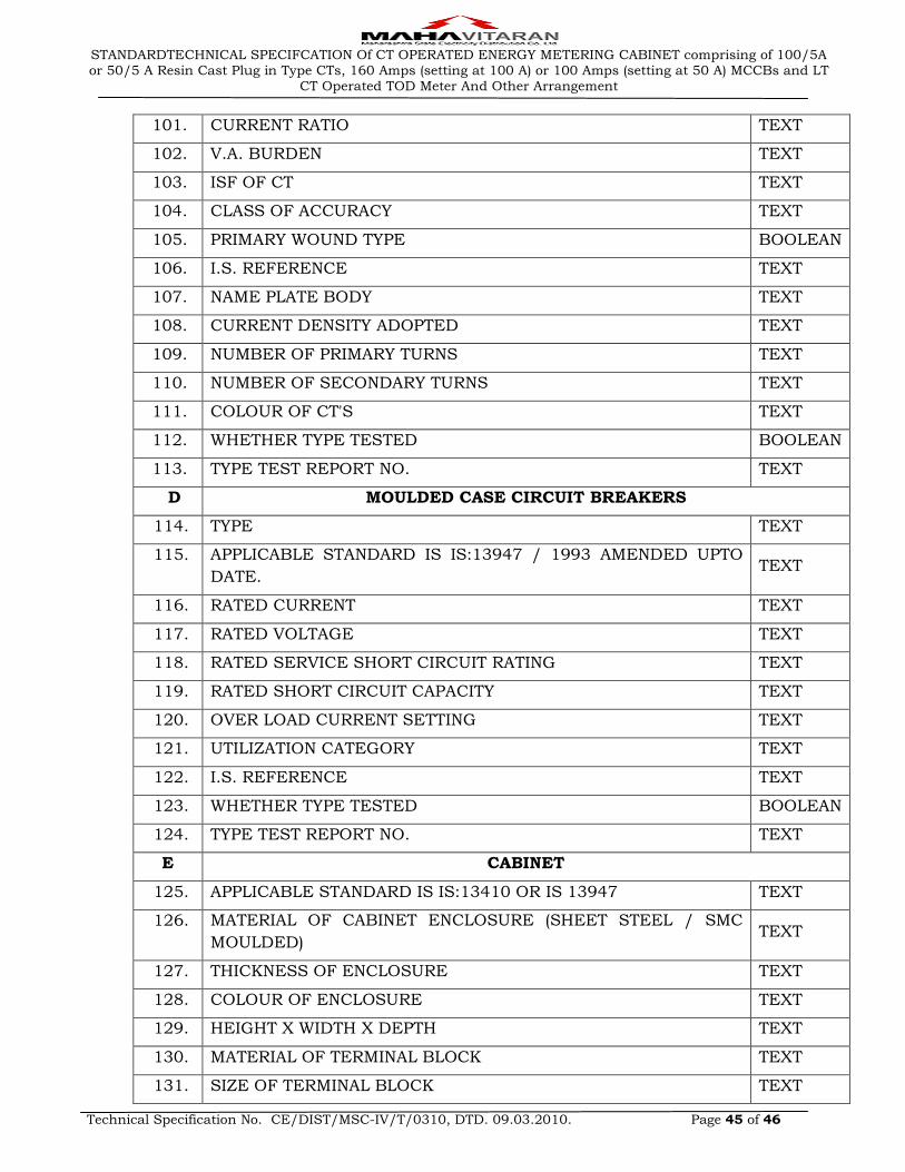
STANDARDTECHNICAL SPECIFCATION Of CT OPERATED ENERGY METERING CABINET comprising of 100/5A or 50/5 A Resin Cast Plug in Type CTs, 160 Amps (setting at 100 A) or 100 Amps (setting at 50 A) MCCBs and LT
CT Operated TOD Meter And Other Arrangement
Technical Specification No. CE/DIST/MSC-IV/T/0310, DTD. 09.03.2010. Page 45 of 46
101. CURRENT RATIO TEXT
102. V.A. BURDEN TEXT
103. ISF OF CT TEXT
104. CLASS OF ACCURACY TEXT
105. PRIMARY WOUND TYPE BOOLEAN
106. I.S. REFERENCE TEXT
107. NAME PLATE BODY TEXT
108. CURRENT DENSITY ADOPTED TEXT
109. NUMBER OF PRIMARY TURNS TEXT
110. NUMBER OF SECONDARY TURNS TEXT
111. COLOUR OF CT'S TEXT
112. WHETHER TYPE TESTED BOOLEAN
113. TYPE TEST REPORT NO. TEXT
D MOULDED CASE CIRCUIT BREAKERS
114. TYPE TEXT
115. APPLICABLE STANDARD IS IS:13947 / 1993 AMENDED UPTO
DATE. TEXT
116. RATED CURRENT TEXT
117. RATED VOLTAGE TEXT
118. RATED SERVICE SHORT CIRCUIT RATING TEXT
119. RATED SHORT CIRCUIT CAPACITY TEXT
120. OVER LOAD CURRENT SETTING TEXT
121. UTILIZATION CATEGORY TEXT
122. I.S. REFERENCE TEXT
123. WHETHER TYPE TESTED BOOLEAN
124. TYPE TEST REPORT NO. TEXT
E CABINET
125. APPLICABLE STANDARD IS IS:13410 OR IS 13947 TEXT
126. MATERIAL OF CABINET ENCLOSURE (SHEET STEEL / SMC
MOULDED) TEXT
127. THICKNESS OF ENCLOSURE TEXT
128. COLOUR OF ENCLOSURE TEXT
129. HEIGHT X WIDTH X DEPTH TEXT
130. MATERIAL OF TERMINAL BLOCK TEXT
131. SIZE OF TERMINAL BLOCK TEXT

STANDARDTECHNICAL SPECIFCATION Of CT OPERATED ENERGY METERING CABINET comprising of 100/5A or 50/5 A Resin Cast Plug in Type CTs, 160 Amps (setting at 100 A) or 100 Amps (setting at 50 A) MCCBs and LT
CT Operated TOD Meter And Other Arrangement
Technical Specification No. CE/DIST/MSC-IV/T/0310, DTD. 09.03.2010. Page 46 of 46
132. MATERIAL OF OUTGOING TERMINAL STRIPS TEXT
133. SIZE OF OUT GOING TERMINAL STRIPS TEXT
134. WHETHER TYPE TESTED BOOLEAN
135. TYPE TEST REPORT NOS. TEXT
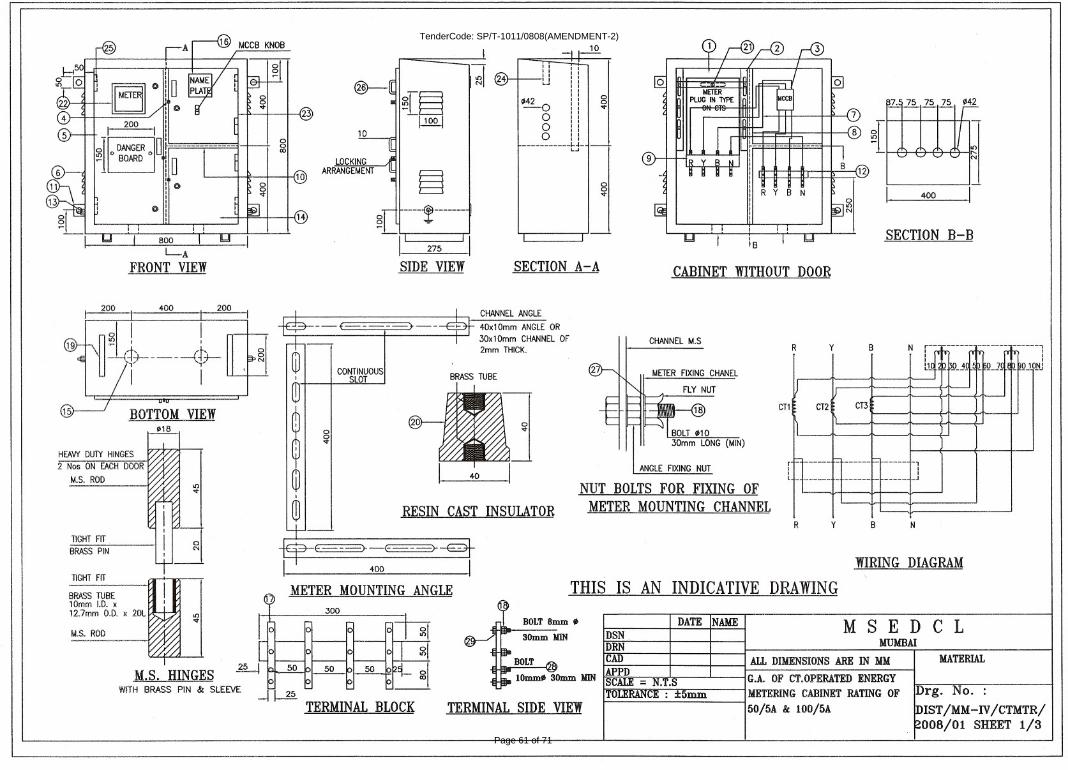
Page 61 of 71
TenderCode: SP/T-1011/0808(AMENDMENT-2)
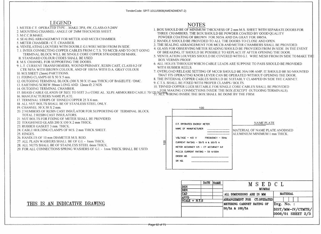
Page 62 of 71
TenderCode: SP/T-1011/0808(AMENDMENT-2)
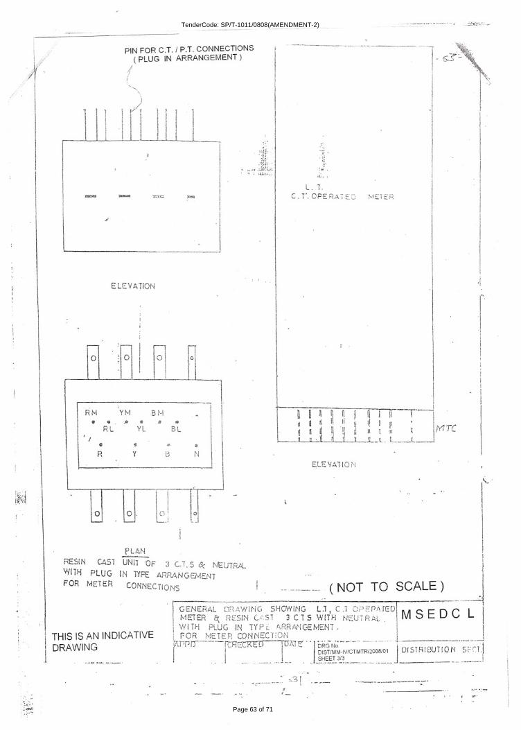
Page 63 of 71
TenderCode: SP/T-1011/0808(AMENDMENT-2)
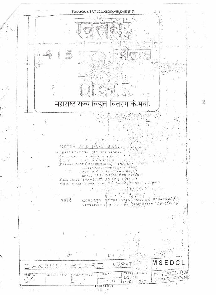
Page 64 of 71
TenderCode: SP/T-1011/0808(AMENDMENT-2)