standard specifications for road and bridge … amd... · for road and bridge construction ... 816...
TRANSCRIPT
STANDARD SPECIFICATIONS
FOR
ROAD AND BRIDGE CONSTRUCTION
EDITION OF 2004
Approved for March 1, 2004
J. M. YowellState Highway Engineer
Copies of this publication may be obtained from:
Transportation CabinetAdministration Services
Division of Management Services200 Mero Street
Frankfort, Kentucky 40622(502) 564-6927

i
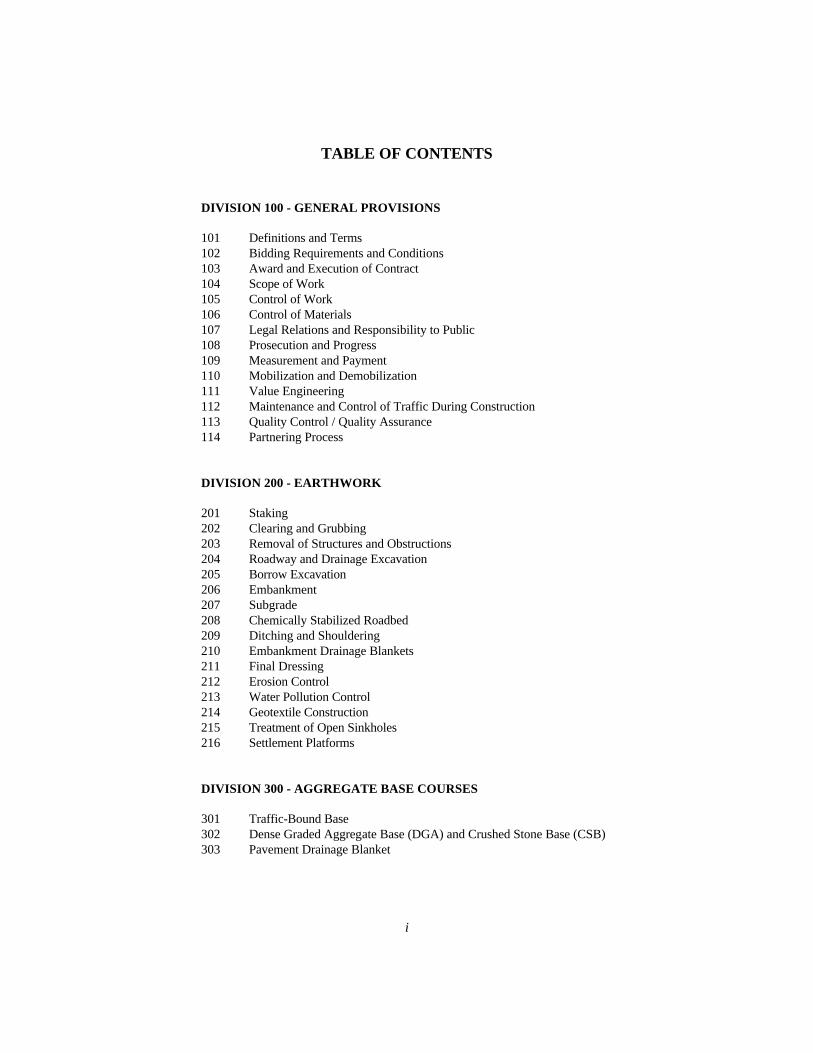
TABLE OF CONTENTS
DIVISION 100 - GENERAL PROVISIONS
101 Definitions and Terms102 Bidding Requirements and Conditions103 Award and Execution of Contract104 Scope of Work105 Control of Work106 Control of Materials107 Legal Relations and Responsibility to Public108 Prosecution and Progress109 Measurement and Payment110 Mobilization and Demobilization111 Value Engineering112 Maintenance and Control of Traffic During Construction113 Quality Control / Quality Assurance114 Partnering Process
DIVISION 200 - EARTHWORK
201 Staking202 Clearing and Grubbing203 Removal of Structures and Obstructions204 Roadway and Drainage Excavation205 Borrow Excavation206 Embankment207 Subgrade208 Chemically Stabilized Roadbed209 Ditching and Shouldering210 Embankment Drainage Blankets211 Final Dressing212 Erosion Control213 Water Pollution Control214 Geotextile Construction215 Treatment of Open Sinkholes216 Settlement Platforms
DIVISION 300 - AGGREGATE BASE COURSES
301 Traffic-Bound Base302 Dense Graded Aggregate Base (DGA) and Crushed Stone Base (CSB)303 Pavement Drainage Blanket

ii
DIVISION 400 - ASPHALT PAVEMENTS
401 Asphalt Plant Requirements402 Control and Acceptance of Asphalt Mixtures403 Production and Placement of Asphalt Mixtures404 Open-Graded Friction Course (OGFC)405 Asphalt Seal Coat406 Asphalt Curing Seal and Asphalt Prime and Tack Coats407 Asphalt Mixture for Pavement Wedge408 Asphalt Pavement Milling and Texturing409 Asphalt Mixture Using Reclaimed Materials410 Asphalt Pavement Ride Quality411 Asphalt Wedge Curbs and Mountable Medians
DIVISION 500 - PCC PAVEMENT AND NON-STRUCTURAL CONCRETE CONSTRUCTION
501 JPC Pavement, PCC Base, and JPC Shoulders502 JPC Pavement 24/48/72503 Diamond Grinding JPC Pavement504 Breaking and Seating JPC Pavement505 Concrete Sidewalks, Steps, and Entrance Pavements506 Concrete Curbs and Gutters507 Concrete Mountable Median and Standard Barrier Median508 Permanent Concrete Median Barriers509 Temporary Concrete Median Barriers510 Sealing and Patching Concrete with Epoxy Resin511 Grouting and Epoxy Bond Coat512 Hook Bolts with Expansion Anchors
DIVISION 600 - STRUCTURES AND CONCRETE
601 Concrete602 Steel Reinforcement603 Foundation Preparation and Backfill604 Bearing Piles605 Prestressed and Precast Concrete Products606 Bridge Restoration and Waterproofing with Concrete Overlays607 Structural Steel Bridges608 Concrete Bridges609 Reinforced Concrete Bridge Slabs610 Concrete Box Culverts and Concrete Headwalls611 Precast Reinforced Concrete Box Culvert Sections612 Structural Plate Soil Interaction Structures613 Retaining Walls614 Maintenance Cleaning and Painting Steel Bridges

iii
DIVISION 700 - DRAINAGE, TRAFFIC, AND ROADSIDECONSTRUCTION
701 Culvert Pipe, Entrance Pipe, Storm Sewer Pipe, and Equivalents702 Slotted Drain Pipe703 Slope Protection and Channel Lining704 Underdrains705 Cored Hole Drainage Box Connector706 Boring and Jacking of Encasement Pipe707 Tunnels by Use of Steel Liner Plates708 Filling and Capping, Safeloading, and Plugging Abandoned Underground
Structures709 Flume Inlets and Paved Ditches710 Small Drainage Structures711 Prefabricated Vertical Wick Drains712 Raised Pavement Markers713 Permanent Pavement Striping714 Durable Pavement Striping715 Panel Traffic Signs716 Roadway Lighting Systems717 Thermoplastic Intersection Markings718 Bridge End Object Markers719 Guardrail720 Metal Handrails721 Fence722 Removing, Resetting, or Replacing Fence723 Right-Of-Way Markers724 Planting Vines, Shrubs, and Trees
DIVISION 800 - MATERIALS DETAILS
801 Cement802 Admixtures for Concrete803 Water804 Fine Aggregates805 Coarse Aggregates806 Asphalt Materials807 Joint Materials808 Waterproofing Materials809 Structural Plates for Pipes, Pipe Arches, and Arches810 Pipe and Pipe Arches811 Steel Reinforcement812 Structural Steels813 Miscellaneous Metals814 Guardrail Systems815 Cast Aluminum Bridge Railing Posts816 Woven-Wire Fencing Materials
iv
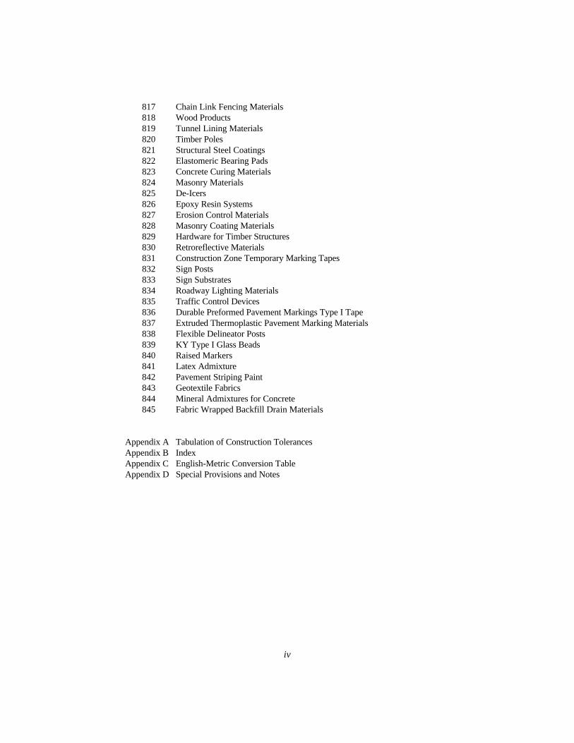
817 Chain Link Fencing Materials818 Wood Products819 Tunnel Lining Materials820 Timber Poles821 Structural Steel Coatings822 Elastomeric Bearing Pads823 Concrete Curing Materials824 Masonry Materials825 De-Icers826 Epoxy Resin Systems827 Erosion Control Materials828 Masonry Coating Materials829 Hardware for Timber Structures830 Retroreflective Materials831 Construction Zone Temporary Marking Tapes832 Sign Posts833 Sign Substrates834 Roadway Lighting Materials835 Traffic Control Devices836 Durable Preformed Pavement Markings Type I Tape837 Extruded Thermoplastic Pavement Marking Materials838 Flexible Delineator Posts839 KY Type I Glass Beads840 Raised Markers841 Latex Admixture842 Pavement Striping Paint843 Geotextile Fabrics844 Mineral Admixtures for Concrete845 Fabric Wrapped Backfill Drain Materials
Appendix A Tabulation of Construction TolerancesAppendix B IndexAppendix C English-Metric Conversion TableAppendix D Special Provisions and Notes

DIVISION 100
GENERAL PROVISIONS

101—1
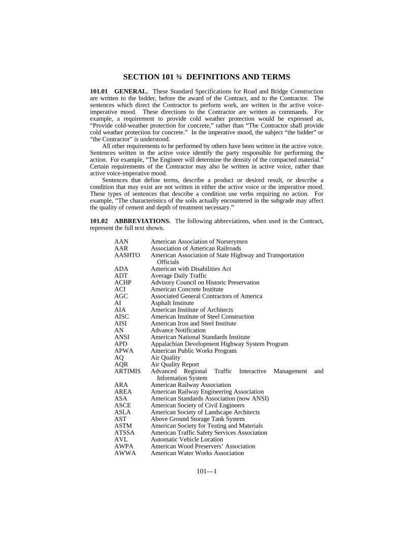
SECTION 101 DEFINITIONS AND TERMS
101.01 GENERAL. These Standard Specifications for Road and Bridge Constructionare written to the bidder, before the award of the Contract, and to the Contractor. Thesentences which direct the Contractor to perform work, are written in the active voice-imperative mood. These directions to the Contractor are written as commands. Forexample, a requirement to provide cold weather protection would be expressed as,“Provide cold-weather protection for concrete,” rather than “The Contractor shall providecold weather protection for concrete.” In the imperative mood, the subject “the bidder” or“the Contractor” is understood.
All other requirements to be performed by others have been written in the active voice.Sentences written in the active voice identify the party responsible for performing theaction. For example, “The Engineer will determine the density of the compacted material.”Certain requirements of the Contractor may also be written in active voice, rather thanactive voice-imperative mood.
Sentences that define terms, describe a product or desired result, or describe acondition that may exist are not written in either the active voice or the imperative mood.These types of sentences that describe a condition use verbs requiring no action. Forexample, “The characteristics of the soils actually encountered in the subgrade may affectthe quality of cement and depth of treatment necessary.”
101.02 ABBREVIATIONS. The following abbreviations, when used in the Contract,represent the full text shown.
AAN American Association of NurserymenAAR Association of American RailroadsAASHTO American Association of State Highway and Transportation
OfficialsADA American with Disabilities ActADT Average Daily TrafficACHP Advisory Council on Historic PreservationACI American Concrete InstituteAGC Associated General Contractors of AmericaAI Asphalt InstituteAIA American Institute of ArchitectsAISC American Institute of Steel ConstructionAISI American Iron and Steel InstituteAN Advance NotificationANSI American National Standards InstituteAPD Appalachian Development Highway System ProgramAPWA American Public Works ProgramAQ Air QualityAQR Air Quality ReportARTIMIS Advanced Regional Traffic Interactive Management and
Information SystemARA American Railway AssociationAREA American Railway Engineering AssociationASA American Standards Association (now ANSI)ASCE American Society of Civil EngineersASLA American Society of Landscape ArchitectsAST Above Ground Storage Tank SystemASTM American Society for Testing and MaterialsATSSA American Traffic Safety Services AssociationAVL Automatic Vehicle LocationAWPA American Wood Preservers’ AssociationAWWA American Water Works Association
101—2
AWS American Welding SocietyBA Biological AssessmentBDR Bridge Development ReportBHR Bridge Hydraulics ReportBMP Best Management PracticesBTEX Benzene, Toluene, Ethylbenzene, XyleneBTS Bureau of Transportation StatisticsCAAA Clean Air Act Amendment (1990)CAD Certified Agricultural DistrictCADD Computer Aided Drawing and DesignCBD Central Business DistrictCDE Chief District EngineerCE Categorical ExclusionCEQ Council on Environmental QualityCERCLA Comprehensive Environmental Response, Compensation and
Liability ActCFR Code of Federal RegulationsCIO Chief Information OfficerCMAQ Congestion Management and Air Quality Improvement ProgramCMS Changeable Message SignCO Carbon MonoxideCOA Class of ActionCOE US Army Corps of EngineersCR County RoadCRA Cultural Resource AssessmentCSRP Conceptual Stage Relocation PlanCRSI Concrete Reinforcing Steel InstituteCTP Comprehensive Transportation PlanCVO Commercial Vehicle OperationsDAQ KNREPC, Division for Air QualitydBA Decibels (A-Weighting)DBE Disadvantaged Business EnterpriseDEA Division of Environmental AnalysisDEIS Draft Environmental Impact StatementDEP Department for Environmental ProtectionDFWR Kentucky Department of Fish and Wildlife ResourcesDHV Design Hourly VolumeDMS Dynamic Message SignDOE Determination of EligibilityDOI US Department of The InteriorDOW KNREPC, Division of WaterDROD Draft Record of DecisionDSEIS Draft Supplementation Environmental Impact StatementDSHE Deputy State Highway EngineerDWM KNREPC, Division of Waste ManagementEA Environmental AssessmentEIS Environmental Impact StatementEO Executive OrderEPA US Environmental Protection AgencyER Federal-Aid Highway Emergency Relief ProgramESA Endangered Species ActESBA Endangered Species Biological AssessmentESAL Equivalent Single Axle LoadFAPG Federal Aid Policy GuideFHPM Federal Highway Program ManualFHWA Federal Highway AdministrationFIA Federal Insurance Administration

101—3
FIRM Flood Insurance Rate MapsFLH Federal Lands Highways ProgramFOIA Freedom of Information ActFONSI Finding of No Significant ImpactFPPA Farmland Protection Policy ActFR Federal RegisterFRA Federal Railroad AdministrationFSEIS Final Supplemental Environmental Impact StatementFSS Federal Specifications and Standards, General Services
AdministrationFTA Federal Transit AdministrationFWS US Fish and Wildlife ServiceFY Fiscal YearGIS Geographic Information SystemGMS Groundwater Management SystemsHABS Historic American Buildings SurveyHAER Historic American Engineering RecordHAR Highway Advisory RadioHC HydrocarbonsHES Hazard Elimination SystemHOV High Occupancy VehicleHTF Highway Trust FundHUD Housing and Urban DevelopmentHZM Hazardous MaterialIA Independent AssuranceICAR Intergovernmental Coordination and ReviewIJR Interchange Justification ReportIM Interstate System/Interstate Maintenance ProgramISTEA Intermodal Surface Transportation Efficiency
Act of 1996 (superseded by TEA-21)ITS Intelligent Transportation SystemJPC Jointed Plain ConcreteKAHC Kentucky Association of Highway ContractorsKM Kentucky MethodKNREPC Kentucky Natural Resources and Environmental
Protection CabinetKRMCA Kentucky Ready Mixed Concrete AssociationKRS Kentucky Revised StatutesKTC Kentucky Transportation CenterKYTC Kentucky Transportation CabinetLeq (h) Level Equivalent for One HourLESA Land Evaluation and Site AssessmentLOS Level of ServiceLTAP Local Technical Assistance ProgramLRP Long Range PlanMAGLEV Magnetic Levitation Transportation Technology
Deployment ProgramMOA Memorandum of AgreementMOU Memorandum of UnderstandingMPO Metropolitan Planning OrganizationMSA Metropolitan Statistical AreaMUTCD Manual on Uniform Traffic Control Devices for Streets and
HighwaysMVE Motor Vehicle EnforcementNAAQS National Ambient Air Quality StandardsNAC Noise Abatement CriterionNAPA National Asphalt Pavement Association
101—4
NCAT National Center for Asphalt TechnologyNCHRP National Cooperative Highway Research ProgramNCR Non-Conformance ReportNDR National Driver RegistrationNEC National Electric CodeNEMA National Electrical Manufacturer’s AssociationNEPA National Environmental Policy ActNFIP National Flood Insurance ProgramNGVD National Geodetic Vertical DatumNHI National Highway InstituteNHPA National Historic Preservation ActNHS National Highway SystemNHTSA National Highway Traffic Safety AdministrationNIST National Institute for Standards and TechnologyNMA Non-Major ActionNMFS National Marine Fisheries ServiceNOAA National Oceanic Atmospheric AdministrationNOV Notice of ViolationNOx Nitrogen OxidesNPDES National Pollutant Discharge Elimination SystemNPHQ National Partnership for Highway Quality formerly
National Quality Initiative (NQI)NPS National Park SystemNRCS National Resources Conservation Service formerly SCSNRHP National Register of Historic PlacesNSR Noise Study ReportNTI National Transit InstituteNTIS National Technical Information ServiceNTPEP National Transportation Product Evaluation ProgramNWIM National Wetland Inventory MapOEP FHWA Office of Environmental PolicyOGC Office of General Counsel, Transportation CabinetOMS Operations Management SystemOPA Office of Public Affairs, Transportation CabinetOSA Office of State ArcheologistOSHA Occupational Safety and Health AdministrationPAH Polynuclear Aromatic HydrocarbonsPAIKY Plantmix Asphalt Industry of KentuckyPCCC Percentage Catalyst Cold-StartPCCN Percentage Catalyst Hot-StartPE Preliminary EngineeringPE Professional EngineerPM10 Inhalable ParticulatesPMS Pavement Management SystemPMS Pavement Marking Systemppm Parts per MillionQA Quality AssuranceQAT Quality Assurance TeamQC Quality ControlQCP Quality Control PlanQL Qualified LaboratoriesRCRA Resource Conservation Recovery ActROD Record of DivisionRS Rural SecondaryRVP Reid Vapor PressureRWIS Road Weather Information StationSAE Society of Automotive Engineers
101—5
SASHTO Southern Association of State Highway andTransportation Officials
SCH State ClearinghouseSCS Soil Conservation ServiceSHA State Highway AgencySHE State Highway EngineerSHRP Strategic Highway Research ProgramSHPO State Historic Preservation OfficerSIC Standard Industrial CodesSIP State Implementation PlanSOx Sulfur OxidesSP State Primary (State Maintained)SPIB Southern Pine Inspection BureauSR State RoadSS State Secondary (State Maintained)SSPC Steel Structures Painting CouncilSTOC Statewide Transportation Operations CenterSTP Surface Transportation ProgramSTIP State Transportation Improvement ProgramSUPP Supplemental Road (State Maintained)SYP Six Year PlanTCM Transportation Control MeasuresTCP Traffic Control PlanTDIP Technology Deployment Initiatives and Partnerships ProgramTE Transportation Enhancement ProgramTEA-21 Transportation Equity Act for the 21st Century (1998-2003)TEBM Transportation Engineer Branch ManagerTIP Transportation Improvement ProgramTMA Transportation Management AreaTMC Transportation Management CenterTRAC Transportation and Civil Engineering ProgramTRIMARC Traffic Response and Incident Management Assisting
the River CitiesTRB Transportation Research BoardTSD Treatment, Storage, and DisposalTSM Transportation Systems ManagementTSO Time Sharing OptionTSP Total Suspended Particulates
UA Urbanized AreaUATS Urban Area Transportation StudyUL Underwriters’ LaboratoryUNL Unscheduled Needs ListUPWP Unverified Planning Work ProgramUSC United States CodeUSCG US Coast GuardUSDA US Department of AgricultureUSDOT US Department of TransportationUSGS US Geological SurveyUSNL Unscheduled Needs ListUST Underground Storage TankVE Value EngineeringVPH Vehicles Per HourVMS Variable Message SignWCLIB West Coast Lumber Inspection BureauWER Wetland Evaluation ReportWMP Wetland Mitigation Plan
101—6
101.03 DEFINITIONS. The following terms, when used in the Contract have themeaning described.
Advertisement A public announcement, inviting Bid Proposals to perform work orfurnish materials.
AuthorizedAdjustment
An order issued by the Engineer to the Contractor detailingchanges to the specified work quantities that do not increase ormodify the scope of the original Contract.
As Built Plans The final Plans reflecting all changes to the original Plans.
Award The acceptance by the Department of a Bid Proposal.
Base Course See definition for Pavement Structure.
Best ManagementPractices
The portion of the QCP detailing how the Contractor intends toconform to the requirements of Section 213 of the StandardSpecifications.
Bidder An individual, partnership, firm, corporation, or any acceptablecombination thereof, or joint venture, submitting a Bid Proposal.
Bid Proposal The offer of a bidder, on the prescribed form, to perform the workand to furnish the labor and materials at the prices quoted.
Bridge A structure, including supports, erected over a depression or anobstruction, such as water, a highway, or a railway, and carryingtraffic or other moving loads via a track or passageway and withan opening measured along the center of the roadway of more than20 feet between undercopings of abutments, spring lines of arches,or extreme ends of openings for multiple boxes.
Bridge Length - The dimension of a structure measured alongthe center of the roadway between backs of abutment headwalls orbetween ends of the bridge floor.
Bridge Roadway Width - The clear width of a structuremeasured at right angles to the center of the roadway between thebottom of curbs or, when curbs are not used, between the innerfaces of a parapet or railing.
Cabinet The Kentucky Transportation Cabinet.
Calendar Day Any day shown on the calendar, beginning and ending atmidnight.
Change Order A written order issued by the Engineer to the Contractor, detailingsignificant changes to the specified work quantities or that increaseor modify the scope of the original Contract.
Channel A natural or artificial watercourse.
Codes Code numbers listed with pay items are bid item code numbersused in project Bid Proposals.
CommercialQuality or Grade
Materials readily available from commercial sources. Thesematerials require no sampling or testing.
101—7
Commissioner Chief Executive Officer of the Department of Highways or a dulyauthorized representative.
Commonwealth The Commonwealth of Kentucky.
ConstructionRevision
Any change in the Plans authorized by the Department.
Contract The written agreement between the Department and the Contractorsetting forth the obligations of the each party for the performanceof the prescribed work. The Contract includes the Bid Proposal,Contract Form, Contract Payment Bond, Contract PerformanceBond, Standard Specifications, Supplemental Specifications,Standard Drawings, Plans, Special Provisions, Special Notes,Notice of Award, Notice to Begin Work, all change orders, and allSupplemental Agreements, all of which constitute one instrument.
Contract Form A document describing the work and the specifications to whichthe work shall be performed, which, when signed by an agent ofboth the Department and the Contractor, binds both parties to theterms described therein.
Contract PaymentBond
The form of security furnished by the Contractor and his surety andapproved by the Commissioner as security for the faithful paymentin full of all legal accounts for labor, materials, and suppliesfurnished in the Contract.
Contract Item orPay Item
A specific unit of work that a price is provided for in the Contract.
ContractPerformance Bond
The security furnished to the Department to guarantee completionof the work according to the Contract.
Contract Time The number of working days or calendar days allowed forcompletion of the Contract. When a calendar date of completion isshown in the Bid Proposal instead of a number of working orcalendar days, complete the Contract by that date.
Contractor The individual, partnership, firm, corporation, or any acceptablecombination thereof, or joint venture, contracting with theDepartment of Highways for performance of the work.
Controlling Itemor Operation
An item or operation that, if delayed, will delay the completiontime of the Contract. The Engineer will determine the controllingitems or operations.
County The county containing the project.
Culvert Any structure not classified as a bridge providing an openingunder the roadway.
Department The Kentucky Department of Highways.
Design Quantity The original Contract quantity not including contingencies.
Detour The directing of traffic onto another roadway to bypass a

101—8
temporary traffic control zone.Diversion The directing of traffic onto a temporary roadway or alignment
placed in or next to the right-of-way.
Employee Any person working on the project who is under the direction orcontrol of, or receives compensation from, the Contractor orsubcontractor.
Engineer The State Highway Engineer of the Department, or a dulyauthorized representative responsible for engineering supervisionof the Contract.
Equipment All machinery and equipment, together with the necessary suppliesfor upkeep and maintenance, and also tools and apparatusnecessary for the proper construction and acceptable completion ofthe work.
Extra Work An item of work not provided for in the Contract as awarded butfound essential by the Engineer for the satisfactory completion ofthe Contract.
Federal Project Any project funded wholly or in part by the Federal Government.
Final Estimate The final Contract payment amount for all quantities of workincluding all changes from the design quantity.
Force Account A basis of payment for the directed performance of highwayconstruction work with payment based on the actual cost of labor,equipment, and materials furnished and considerations foroverhead and profit according to Subsection 109.04.
FormalAcceptance
Acceptance by the Department which relieves the Contractor offurther obligation for the work performed.
Highway A general term denoting a public way for purposes of vehiculartravel, including the entire area within the right-of-way.
HighwaySeparation
Any structure carrying highway traffic over or under anotherhighway or street.
Highway-RailwaySeparation
Any structure carrying highway traffic over or under the tracks ofany railway.
Holidays New Year’s Day. The first day of January plus one other daydetermined by the Governor of Kentucky each year.Martin Luther King Day. The third Monday in January.Good Friday. Friday before Easter.Memorial Day. The last Monday in May.Independence Day. The fourth day of July.Labor Day. The first Monday in September.Presidential Election Day. The first Tuesday after the firstMonday in November of presidential election years.Veteran’s Day. The eleventh day of November.Thanksgiving Day. The fourth Thursday in November plus thefollowing Friday.Christmas Day. The twenty-fifth day of December plus one other
101—9
day determined by the Governor of Kentucky each year.
These holidays are subject to subsequent changes by the GeneralAssembly of the Commonwealth of Kentucky.
IndependentAssurance
The Department’s Division of Materials will conduct testing toprovide an unbiased and independent evaluation of all samplingand testing procedures used in the acceptance program.
Inspector The Engineer’s authorized representative assigned to makedetailed inspections of Contract performance.
Laboratory The official testing laboratory of the Department.
Local Traffic Traffic that has either its origin or destination at some point withinthe limits of the project or an adjacent project. Local trafficincludes traffic on all side roads that lead into the project withoutanother satisfactory outlet over a passable road or street and schoolbuses and mail delivery vehicles making stops within the project.
Major and MinorItems
All original Contract items having a value of 10 percent or more ofthe original Contract amount, based on the original Contract priceand original estimated quantity, are major items. All remainingitems are minor items.
Masonry Concrete or stone masonry.
Materials Any substances used in connection with the construction andmaintenance of any structure or the roadway and itsappurtenances.
Median The portion of a divided highway separating the traveled ways fortraffic moving in opposite directions.
Minor Structures Any structure not classified or defined as a bridge or a culvert,including catch basins, inlets, manholes, retaining walls, steps,buildings, fences, and other miscellaneous items.
New Never been used before.
Non–ConformanceReport
A formal written document of notification detailing a deficiency, ornon-conformance in characteristic, documentation, or procedure,which renders the quality of an item or activity unacceptable orindeterminate. Corrective action is required, including but notlimited to, supportive documentation of correction for thedeficiency.
Notice of Award Written notice to the Contractor stating that their Bid Proposal hasbeen accepted by the Cabinet.
Notice toContractors
The official notice inviting bids for the proposed highwayimprovements.
Notice to BeginWork
Written notice to the Contractor to proceed with the Contract work.When applicable, the Engineer will begin counting Contract time(working days) starting with the Notice to Begin Work date.
101—10
Quality Assurance QA consists of all planned and systematic actions necessary toprovide adequate confidence that a product or service will satisfyspecified requirements for quality. QA serves to provideconfidence in the Contract requirements, which include materialshandling and construction procedures, calibration and maintenanceof equipment, production process control and any sampling,testing and inspection which is performed by the Department forthese purposes.
Quality AssuranceTeam
Department teams which check the validity of the QCP to ensureall work is in accordance with the Contract.
Quality Control The sum total of activities performed by the Contractor to ensurethe end product meets the Contract requirements.
Quality ControlPlan
A detailed description in manual format of the type and frequencyof inspection, staffing, materials handling and constructionprocedures, calibration and maintenance of equipment, productionprocess control, sampling, and testing deemed necessary tomeasure and control quality as specified by the Contractdocuments.
QualifiedLaboratories
Department approved laboratories used for sampling and testing ofmaterial.
PavementStructure
The combination of base course and surface course placed on asubgrade to support the traffic load and distribute it to the roadbed.
Subgrade. The top surface of a roadbed upon which thepavement structure and shoulders including curbs are constructed.
Base Course. The layer or layers of specified or selectedmaterials of designed thickness placed on a subgrade to support asurface course.
Surface Course (Wearing Course). One or more layers of apavement structure designed to accommodate the traffic load, thetop layer of which resists skidding, traffic abrasion, and thedisintegrating effects of climate.
Pay Item orContract Item
A specific unit of work that a price is provided for in the Contract.
Plans The approved Contract drawings including the plan, profile, andcross section sheets; general notes; the working drawings;supplemental drawings; and construction revisions showing thelocation, type, character, dimensions, and details of the workrequired.
ProfessionalArchaeologist
An individual with a Masters degree in archaeology oranthropology, or an individual with Society of ProfessionalArchaeologists certification, specializing in historic or prehistoricarchaeology and having field experience in archaeologicalinvestigation.
Profile Grade The trace of a vertical plane intersecting the top surface of theproposed wearing surface, usually along the longitudinal centerlineof the roadbed. Profile grade means either the elevation orgradient of such trace according to the context.
101—11
Project The specific section of the highway, including approaches and allappurtenances, and construction to be performed under theContract.
ProjectCompletion
The satisfactory completion of all work relating to both ContractBid Proposal items and items added by supplemental agreement.
ProjectCompletion Notice
The notice issued by standard form that the Project has beensatisfactorily completed and is ready for final inspection.
Proper LocalAuthorities
Officials authorized by law to act for counties and other civilsubdivisions.
Proposal Guaranty The security furnished with a Bid Proposal guaranteeing that abidder submitting an accepted Bid Proposal enters into theContract.
Ramp An interconnecting roadway of a traffic interchange, or aconnection between highways at different levels or betweenparallel highways on which vehicles may enter or leave adesignated roadway.
Responsive Bid A Bid Proposal which conforms to all requirements of the proposalpamphlet.
ResponsibleBidder
A bidder that is a responsible Contractor.
ResponsibleContractor
A Contractor that has the requisite skill, resources, desire, andintegrity to complete the work in conformance with the provisionsof the Contract.
Right-of-Way A general term denoting land, property, or interest, acquired for ordevoted to transportation purposes.
Road A general term denoting a public way for purposes of vehiculartravel, including the entire area within the right-of-way.
Roadbed The graded portion of a highway within the top and side slopes,prepared as a foundation for the pavement structure, shoulders,and median.
Roadside A general term denoting the area adjoining the outer edge of theroadway. Extensive areas between the roadways of a dividedhighway may also be considered roadside.
RoadsideDevelopment
Those items necessary to the complete highway providing for thepreservation of landscape materials and features; the rehabilitationand protection against erosion of all areas disturbed byconstruction through seeding, sodding, mulching, and the placingof other ground covers; such suitable planting and otherimprovements as may increase the effectiveness and enhance theappearance of the highway.
Roadway The portion of a highway within the limits of construction.
101—12
Shoulder The portion of the roadway contiguous with the traveled way foraccommodation of stopped vehicles, for emergency use, and forlateral support of base and surface courses.
Sidewalk That portion of the roadway outside normal vehicle pathsconstructed primarily for the use of pedestrians.
Skew or SkewAngle
The acute angle formed by the intersection of a line normal to thecenterline of the roadway with a line parallel to the face of theabutments, or in the case of culverts, with the centerline of theculverts.
Special Notes See definition for Specifications.
Special Provisions See definition for Specifications.
Specifications A general term applied to written directions, provisions, andrequirements pertaining to performance of the work.Specifications are included in documents such as the SpecialNotes, Special Provisions, Standard Specifications, orSupplemental Specifications.
Special Notes. Specifications developed for a specific item ofwork which may be appropriate only for a particular project butmay become standard if regularly used as future projects using theitem develop.
Special Provisions. Specifications developed for a specificitem of work which may be appropriate only for a particularproject but may become standard if regularly used as futureprojects using the item develop.
Standard Specifications. A book of specifications approvedfor general application and repetitive use by the Departmententitled, “Standard Specifications for Road and BridgeConstruction”.
Supplemental Specifications. Additions and revisions to theStandard Specifications that are made subsequently to issuance ofthe Standard Specifications.
SpecifiedCompletion Date
The date by which the Contract work is specified to be completed.
StandardDrawings
Detailed drawings approved for repetitive use.
StandardSpecifications
See definition for Specifications.
State HighwayEngineer
The State Highway Engineer of the Department acting directly orthrough an authorized representative.
Street A general term denoting a public way for purposes of vehiculartravel in a city, including the entire area within the right-of-way.
Structures Bridges, culverts, or minor structures.
Subcontractor An individual, firm, or corporation who, with the written consentof the Department, subcontracts any part of the Contract. First tier
101—13
Subcontractors are those to whom the Contractor subcontracts aportion of the work. Second tier Subcontractors are those to whoma first tier Subcontractor subcontracts a portion of the work.
Subgrade See definition for Pavement Structure.
Substructure All of that part of the structure below the bearings of simple andcontinuous spans, skewbacks of arches and tops of footings orrigid frames, together with the back walls, wingwalls, and wingprotection railings.
Superintendent The Contractor’s authorized representative in responsible charge ofthe work.
Superstructure The entire structure except the substructure.
SupplementalAgreement
A written agreement executed by the Contractor and theCommissioner, with the consent of the surety when required,covering significant changes, and revised or new unit prices anditems, that supplements the original Contract.
SupplementalDrawings
Drawings included in the Plans to specify construction details.
SupplementalSpecifications
See definition for Specifications.
Surety The corporation, firm, or individual, other than the Contractor,executing a bond furnished by the Contractor.
Surface Course(Wearing Course)
See definition for Pavement Structure.
TemporaryStructures
Structures required for the use of traffic during construction andnot remaining a part of the permanent roadway.
Through Traffic All traffic other than traffic defined as Local Traffic.
Titles or Headings The titles or headings of the Sections and Subsections herein areintended for convenience of reference and shall not have anybearing on their interpretation.
Traveled Way The portion of the roadway used for the movement of vehicles,exclusive of shoulders and auxiliary lanes.
Work The furnishing of all labor, materials, equipment, and otherincidentals necessary or convenient to the successful completion ofthe project or Contract item and the performance of all duties andobligations imposed by the Contract.
Working Day A calendar day, exclusive of Saturday, Sunday, holidays, or dayswhen the weather, seasonal, or temperature limitations of thespecifications, or other conditions beyond the control of theContractor, prevent, as judged by the Engineer, constructionoperations from proceeding for at least 5 hours by the normalworking force engaged in performing the controlling item or itemsof work.

101—14
Working Drawings Stress sheets, shop drawings, erection plans, falsework plans,framework plans, cofferdam plans, bending diagrams forreinforcing steel, or any other supplementary plans or similar datathe Contractor is required to submit to the Engineer for review.
102—1
SECTION 102 BIDDING REQUIREMENTS ANDCONDITIONS
102.01 PREQUALIFICATION OF BIDDERS. All organizations and individualsbidding on Department projects and accepting subcontracts on Department projects mustapply for and receive Department prequalification and possess a Certificate of Eligibilityas provided in regulations published by the Department according to KRS Section176.140.
The Department reserves the right to waive this requirement on certain projects inconnection with the letting of contracts not covered by the statutes. The Department willplace a waiver of this requirement in the Notice to Contractors and the Bid Proposal forsuch projects.
102.02 CURRENT CAPACITY RATING. The Department will determine thecurrent capacity rating of a bidder as the net difference between the bidder’s maximumcapacity rating as set forth in a Certificate of Eligibility and the total value of uncompletedContract work, held as a prime contractor, that the bidder is performing for any owner.
The Department will determine the value of uncompleted Contract work, held as aprime contractor, that the bidder is performing from the last approved pay estimate foreach uncompleted Contract. The Department will not give credit for any worksubcontracted.
The Department will divide the total Bid Proposal of a joint venture equally amongthe participants in the joint venture. The Department will divide the total value of theuncompleted work of joint ventured projects equally among the joint venturers indetermining a bidder’s current capacity rating.
The Department will not consider Bid Proposals exceeding the current capacity ratingof a bidder.
102.03 CONTENTS OF THE BID PROPOSAL FORM. Upon request, theDepartment will furnish the prospective bidder with a Bid Proposal form. The form statesthe location and description of the contemplated construction and shows the approximateestimate of the various quantities and kinds of work to be performed or materials to befurnished, and includes a schedule of items for which unit bid prices are invited. The BidProposal form states the time allowed to perform the work, the amount of the ProposalGuaranty, and the date, time, and place of the opening of the Bid Proposals. The form alsoincludes any special provisions or requirements varying from or not contained in theStandard Specifications.
The Department considers all papers bound with or attached to the Bid Proposal forma part of the Bid Proposal. Do not detach or alter any parts of the submitted Bid Proposal.
The Department considers the Plans, Specifications, and other documents designatedin the Bid Proposal form a part of the Bid Proposal whether attached or not.
The prospective bidder must pay the Department the sum stated in the Notice toContractors for each copy of the Bid Proposal form.
102.04 ISSUANCE OF BID PROPOSAL FORM. The Department reserves the rightto disqualify or refuse to issue a Bid Proposal form to a potential bidder for any of thefollowing reasons:
1) failure to comply with any prequalification regulations of the Department;2) default under previous contracts;3) when a bidder’s existing, uncompleted contracts and subcontracts with the
Department are behind schedule to the extent that they might hinder or preventprompt completion of any additional contracts;
4) when either the actual progress for all of a bidder’s existing grade and drain; or grade,drain, and surfacing; or bridge contracts and subcontracts is 20 percent or morebehind the scheduled progress for the contracts and subcontracts, or when any one of
102—2
the bidder’s contracts or subcontracts is 30 percent or more behind schedule;5) when the average actual progress for all of a bidder’s surfacing or resurfacing,
seeding, signing, or other miscellaneous contracts and subcontracts is 50 percent ormore behind the scheduled progress or when any one of these contracts orsubcontracts exceeds the original Contract time or completion date without significantcause;
6) failure to reimburse the Commonwealth for monies owed on any previously awardedcontracts, including those contracts where the prospective bidder is party to a jointventure and the joint venture fails to reimburse the Commonwealth for monies owed;and
7) failure to reimburse the Commonwealth for monies owed for plans and Bid Proposalforms.
The Department will resume issuing Bid Proposal forms to the bidder only after thebidder improves his operations to the satisfaction of the State Highway Engineer.
102.05 INTERPRETATIONS OF QUANTITIES IN BID SCHEDULE. TheDepartment’s estimated quantities appear in the bid schedule only for the purpose ofcomparing the Bid Proposals. The Department will pay the Contractor only for the actualquantities of work performed and accepted or materials furnished according to theContract. The Department may increase, decrease, or omit the estimated quantities ofwork and materials furnished.
102.06 EXAMINATION OF PLANS, SPECIFICATIONS, SPECIALPROVISIONS, SPECIAL NOTES, AND SITE OF WORK. Examine the site of theproposed work, the Bid Proposal, Plans, specifications, and contract forms, beforesubmitting the Bid Proposal. The Department considers the submission of a Bid Proposalprima facie evidence that the bidder has made such examination and is satisfied as to theconditions to be encountered in performing the work and as to the requirements of theContract.
Professing ignorance or a misunderstanding regarding requirements of the work doesnot in any way serve to modify the provisions of the Contract.
102.07 PREPARATION OF BID PROPOSAL.
102.07.01 General. Submit the Bid Proposal on the forms furnished by theDepartment including the Highway Bid Program bid item sheets and disk created from theDepartment's internet web site. Specify a unit price in figures for each pay item for whicha quantity is given and show the products of the respective unit prices and quantitieswritten in figures in the column provided for that purpose. Round the products bydropping all digits past the cent. Indicate the total amount of the Bid Proposal, obtainedby adding the rounded amounts of the items. Write in ink or type all figures.
When an item in a Bid Proposal allows a bidder to make a choice, indicate a choiceaccording to the specifications for that particular item.
Sign Bid Proposals in ink using the individual, one or more members of thepartnership, one or more members of each firm representing a joint venture, one or moreofficers of a corporation, or an agent of the bidder legally qualified and acceptable to theDepartment. When proposing as an individual, indicate the name and post office addressof the individual. When proposing as a partnership, indicate the name and post officeaddress of each partnership member. When proposing as a joint venture, indicate thename and post office address of each member or officer of the firms represented by thejoint venture. When proposing as a corporation, indicate the name of the corporation andthe business address of its corporate officials.
102.07.02 Computer Bidding. Subsequent to ordering a Bid Proposal for a specificproject, use the Department's Highway Bid Program on the internet web site of theDepartment of Highways, Division of Contract Procurement. Download the bid item
102—3
quantities from the Department's web site to prepare a Bid Proposal for submission to theDepartment. Insert the completed bid item sheets printed from the Highway Bid Programinto the Proposal and submit along with the disk created by said program.
In case of a dispute, the Bid Proposal and bid item sheets created by the Highway BidProgram take precedence over any bid submittal.
Furthermore the Department takes no responsibility for loss, damage of disks or thecompatibility with the bidder's computer equipment or software.
102.08 IRREGULAR BID PROPOSALS. The Department will consider BidProposals irregular and will reject them when the bidder either:
1) omits both a unit price for any pay item and an amount for the entire quantity of thesame pay item, except when the Bid Proposal allows a choice of authorized pay items;or
2) submits zero as a unit price for any pay item or as an amount for the entire quantity ofthe same pay item except when the Bid Proposal form allows a choice of authorizedpay items; or
3) fails to submit the bid on the current revised pay items; or4) fails to submit a disk created from the Highway Bid Program.
The Department will consider Bid Proposals irregular and may reject them for thefollowing reasons:
1) when the Bid Proposal is on a form other than that furnished by the Department orprinted from other than the Highway Bid Program , or when the form is altered or anypart is detached; or
2) when there are unauthorized additions, conditional or alternate bids, or irregularitiesof any kind which may tend to make the Bid Proposal incomplete, indefinite, orambiguous as to its meaning; or
3) when the bidder adds any provisions reserving the right to accept or reject an award,or to enter into a Contract pursuant to an award; or
4) any failure to comply with the provisions of Subsection 102.07; or5) Bid Proposals in which the Department determines that the prices are unbalanced; or6) when the sum of the total amount of the Bid Proposal under consideration exceeds the
bidder’s Current Capacity Rating.
102.09 BID PROPOSAL GUARANTY. The Department will reject and will not readany Bid Proposal that is not accompanied by a guaranty in the form of a cashier’s check,certified check, or bid bond and in an amount no less than the amount indicated on the BidProposal form. Make the cashier’s check, certified check, or bid bond payable to theKentucky State Treasurer.
102.10 DELIVERY OF BID PROPOSALS. Submit each Bid Proposal in a specialenvelope furnished by the Department. Correctly fill in the blank spaces on the envelopeto clearly indicate its contents. When using an envelope other than the envelope furnishedby the Department, use an envelope of the same general size and shape similarly marked toclearly indicate its contents. When sent by mail, address the sealed Bid Proposal to theDepartment at the address and in care of the office and official receiving the Bid Proposals.Submit all Bid Proposals prior to the time and at the place specified in the Notice toContractors. The Department will time-stamp and return to the bidder unopened BidProposals received after the time for opening of bids.
102.11 WITHDRAWAL OR REVISION OF BID PROPOSALS. A bidder maywithdraw or revise a Bid Proposal after depositing the Bid Proposal with the Department,provided the Department receives the request for such withdrawal or revision in writing orby telegram before the time set for opening Bid Proposals.
102—4
102.12 COMBINATION BID PROPOSALS. The Department may issue BidProposals for projects in combination or separately. Submit Bid Proposals on either thecombination or the separate projects of the combination. The Department reserves theright to make awards on combination bids or separate bids to the best advantage of theDepartment.
102.13 PUBLIC OPENING OF BID PROPOSALS. The Department will publiclyopen and read all Bid Proposals at the time and place indicated in the Notice toContractors, or at any other location the Department designates.
102.14 DISQUALIFICATION OF BIDDERS. The Department may consider any ofthe following reasons sufficient for the disqualification of a bidder and the rejection of thebidder’s Bid Proposal(s):
1) more than one Bid Proposal for the same work submitted by an individual, firm, orcorporation under the same or different name;
2) evidence of collusion among bidders. The Department will not recognize participantsin such collusion as bidders for any future Department work until the Departmentreinstates such participant as a qualified bidder.
Collusive bidding is a violation of the law and may result in criminalprosecution, civil damage actions, and State and Federal administrative sanctions.
102.15 PROCESS AGENT. Every corporation doing business with the Departmentshall submit evidence of compliance with KRS Sections 271A.070, 271A.385, 271A.555,271A.565, and 271A.615, and file with the Department the name and address of theprocess agent upon whom process may be served.
Every individual residing in another state, or members of a co-partnership who residein another state, doing business with the Department shall file with the Department thenames and addresses of at least 2 persons residing in Kentucky upon whom process maybe served.
When any change is made in any such corporation’s, individual’s, or co-partnership’sprocess agent, the corporation, individual, or co-partnership shall immediately file with theDepartment a statement of the change. The former agent shall remain agent for thepurpose of service of process until the bidder files a statement with the Departmentdesignating the new agent.
Submit or file evidence of compliance with the KRS Sections cited above and/ordesignation of process agents, as required by this section, with the Department at the timeof qualifying or at the time of submitting a Bid Proposal, or at any time prior to theissuance of the Contract and work order and/or purchase order.
103—1
SECTION 103 AWARD AND EXECUTION OF CONTRACT
103.01 CONSIDERATION OF BID. The Department will tabulate the bid as soon aspossible after opening the Bid Proposals and will compare the bids based on a correctsummation of items at the prices bid. The Department will then make the result public. Inthe event of a discrepancy between unit bid prices and extensions, the Department will usethe unit bid price. The Commissioner reserves the right to reject any or all Bid Proposalsand to waive minor technicalities if doing so is in the best interest of the Commonwealth.
103.02 AWARD OF CONTRACT. Unless rejecting all Bid Proposals, theDepartment will award the Contract to the lowest responsible bidder, withoutdiscrimination on the grounds of race, creed, color, sex, or national origin, whose BidProposal complies with the requirements of the law, the regulations, and the Contract.
The Department may reject unbalanced Bid Proposals and award the Contract to thenext lowest acceptable bidder.
The Department will award the Contract within 10 calendar days after the date ofreceiving Bid Proposals unless the Department deems it best to hold the Bid Proposals ofany or all bidders for a period not to exceed 60 calendar days for final disposition of award.The Department may hold the Bid Proposal of the lowest bidder longer than 60 days if thebidder concurs. The Department will mail the official Notice of Award to the addressshown on the Contractor’s Certificate of Eligibility.
103.03 CANCELLATION OF AWARD. The Department reserves the right to cancelthe award of any contract at any time before the execution of that contract by all partieswithout any liability against the Department.
103.04 RETURN OF PROPOSAL GUARANTIES. The Department will return theProposal Guaranties of all except the 2 lowest bidders within 5 calendar days afterchecking, tabulating, and comparing the Bid Proposals. The Department will hold theProposal Guaranty of the lowest bidder and the Proposal Guaranty of the second lowestbidder, as determined by the Commissioner, until the Department awards the Contract andexecutes and approves the Contract and bonds of the successful bidder, or until theDepartment rejects all Bid Proposals. If the Department does not make an award within60 calendar days, the Department will return all Proposal Guaranties.
The Department will not release a bidder from the obligations of the Bid Proposalbecause of an alleged error in the preparation of the Bid Proposal unless the Departmentretains the bidder’s Proposal Guaranty.
103.05 REQUIREMENT OF CONTRACT BONDS. To be acceptable to theDepartment, the surety must have a minimum A. M. Best rating of an “A-”, be listed onthe U.S. Treasury Listing of approved sureties for an amount equal to or greater than theamount of the bond and be an admitted carrier in the Commonwealth of Kentucky. SubmitContract bonds conditioned upon the faithful performance of the requirements of theContract and any modifications in conformity with the Contract; payment of propercompensation under the required labor and wage conditions as provided in the Contract;payment of claims against the Contractor for materials, labor and supplies; andreimbursement to the Department for any overpayment made on the Contract. Maintainthe Contract bonds in full force for the time required by law. If at any time during theperformance of the Contract the surety company falls below the minimum acceptablerequirements, the Contractor shall file new bonds in an amount established by theCommissioner, or his designee, within 14 calendar days of such failure to meet theminimum requirements.
The surety of the Contract bonds shall only sign a prescribed form through a dulyappointed power of attorney with certifications acceptable to the Department. File anattested copy of all certifications of attorneys-in-fact with the Franklin County Court Clerkprior to submission to the Department and file a certified copy with the Department.
103—2
All non-resident agents of Kentucky signing the bonds as representatives of a suretycompany shall obtain the countersignature of a licensed Kentucky agent of the insurer asrequired by law. All appointments of attorneys-in-fact shall contain a provision that theappointment will not be revoked without giving the Department notice in writing at least30 calendar days prior to the effective date of the revocation and filing same with theFranklin County Court Clerk. More than one surety may execute a bond for any oneContract, and, in such event when 2 or more sureties are provided on such bond, eachsurety shall be liable and obligated for the full amount required herein before.
The Department reserves the right to copy the surety on all of its communications withthe Contractor concerning the Contractor’s performance, or performance deficiencies, onthe project and further reserves the right to communicate directly with the surety to informthem of the Contractor’s performance, or performance deficiencies, on the bonded project.
103.06 EXECUTION OF CONTRACT. Within 15 calendar days after receiving theContract, execute and file it with the Department along with the following items:
1) the Contract bonds required in Subsection 103.05;2) satisfactory evidence of required liability insurance;3) satisfactory evidence of compliance with Subsection 102.15;4) when the bidder lists proposed subcontractors in the Bid Proposal, and the amount of
work proposed to be subcontracted is not to be deducted from the bidder’s currentcapacity rating, then submit Form TC 14-9, Confirmation of Subcontract, reported inthe Bid Proposal. Sign submittal and obtain signatures of each proposedsubcontractor. Verify all signatures by a notary public.
5) when the Bid Proposal form designates a certain percentage of the Contract as theDisadvantaged Business Enterprise (DBE) portion, submit the necessary number ofagreements with DBEs to meet or exceed these designated percentages. Execute anagreement with each DBE that includes the items of work, the unit price that the DBEwill be paid for each item, and notarized signatures of both parties. Should the bidderfail to reach the designated DBE percentages, then the Department will considerwhether the bidder made reasonable efforts to meet these percentages prior to issuinga work order.
Execute the Contract and bonds only on the form furnished by the Department. Uponthe filing with the Department by the Contractor of the executed Contract accompanied bythe listed items, the Commissioner will, within the period not exceeding 30 calendar daysfrom the date of such filing, make final disposition of the Contract and, if Contract bondsare approved, will issue Notice to Begin Work. Should the Department withhold theNotice to Begin Work in excess of the 30 calendar day period, the Contractor shall havethe option of accepting or rejecting the Contract without forfeiting the Proposal Guaranty.
103.07 APPROVAL OF CONTRACT. The Contract is not binding until theCommissioner executes it and certain agencies of the Commonwealth, as required by law,certify that sufficient funds are available.
103.08 FAILURE TO EXECUTE CONTRACT. The bidder’s failure to execute theContract or to comply with all requirements of Subsection 103.06 within 15 calendar daysafter the Contract has been received by the bidder will be just cause for the Department tonullify the award. It is understood by both the bidder and the Commissioner that, in theevent of the annulment of the award, the bidder will forfeit the amount of guarantydeposited with the Bid Proposal as agreed liquidated damages to the Commonwealth; notas a penalty, but in liquidation of damages sustained. The Department can then make anaward to the next lowest responsible bidder; or readvertise the work or take other action asprovided by statute on this subject, as the Commissioner may elect. A bidder who forfeitsa Proposal Guaranty according to this Section will not be considered in future bidproposals for the same project unless there has been a substantial change in the design ofthe project subsequent to the forfeiture of the Guaranty.
104—1
SECTION 104 SCOPE OF WORK
104.01 INTENT OF CONTRACT. The intent of the Contract is to provide for theconstruction and completion in every detail of the work described. Furnish all labor,materials, equipment, tools, transportation, and supplies required to complete the workaccording to the Contract.
104.02 ALTERATIONS OF PLANS OR CHARACTER OF WORK.
104.02.01 General. At any time, and without invalidating the Contract or releasingthe surety, the Engineer reserves the right to make, in writing, changes in quantities andalterations in the work when necessary to complete the project satisfactorily. Perform thework as altered.
When alterations or changes in quantities significantly change the character of thework under the Contract, the Department will adjust the Contract. The Department willnot consider loss of anticipated profits. Before performing the significantly changed work,reach agreement with the Department concerning the basis for the adjustment. Absent anagreement, the Engineer will determine a fair and equitable adjustment.
If the alterations or changes in quantities do not significantly change the character ofthe work, the Department will make payment as provided elsewhere in the Contract. Asignificant change occurs when:
1) the character of the work is altered materially in kind or nature from that involvedor included in the original proposed construction or,
2) the quantity of a major item of work, as defined in Subsection 101.03, increasesabove 125 percent or decreases below 75 percent of the original Contractquantity. The Department will allow an adjustment in cost only for the quantityin excess of 125 percent of the original Contract quantity, or in case of a decreasebelow 75 percent, to the actual amount of work performed.
104.02.02 Overrun and Underrun Formulas. The Department will use thefollowing supplemental formulas to determine the adjusted unit prices for the items listedherein when a listed item is a major item, and when either an underrun or overrun of morethan 25 percent occurs in the quantity of that major item constructed.
The excessive underrun of an item is defined as 75 percent of the original Contractquantity of the item minus the final quantity of the item. The excessive overrun of an itemis defined as the final quantity of the item minus 125 percent of the original Contractquantity of the item.
The Department will apply this subsection when all the following conditions are met:
1) an excessive underrun or overrun occurs for one or more of the bid items listedbelow;
2) the affected item is a major item, as defined in Subsection 101.03; and3) the final quantity of the affected item is at least 30 percent of the original
Contract quantity. When the final quantity of the affected item is less than 30percent of the original Contract quantity, the Department will not apply theformula but will prepare a supplemental agreement according to Subsections109.03 and 109.04.
The specified bid items which are covered by this subsection are:
• Pavement Markers• Pavement Striping (temporary and permanent)• Temporary Marking Tape• Delineators• Asphalt Pavement Milling and Texturing
104—2
• Concrete Overlay Latex• Concrete Overlay Low Slump• Concrete Class M for Full Depth Patching
The Department will apply this subsection to other bid items when specified in theContract.
For the excessive underrun and overrun quantities, the Department will adjust thepayment according to the appropriate following formula:
Excessive Underrun Formula
NP = OP + (EU x 0.25 x OP) FQCI
Excessive Overrun Formula
NP = OP - (EO x 0.25 x OP) FQCI
Where:
NP = New Unit PriceOP = Original Unit Price Bid by ContractorEU = Excessive UnderrunEO = Excessive OverrunFQCI = Final Quantity Contract Item
When the Contractor submits a completed Bid Proposal for a project containing oneor more of the listed items, the Contractor agrees to accept payment for excessiveunderruns or excessive overruns in the quantities of these items according to theappropriate formula. The Contractor further agrees that the formulas provide full andcomplete compensation for the excessive underrun or excessive overrun quantities,including any and all unreimbursed expenses, loss of expected reimbursement, loss ofanticipated profits, delay, inefficiency, and all other costs.
104.02.03 Differing Site Conditions. Differing site conditions exist when one partydiscovers that:
1) subsurface or latent physical conditions differ materially from those shown in theContract, or
2) unknown subsurface or latent physical conditions differ materially fromconditions normally encountered or from those generally recognized as inherentin the work provided for in the Contract.
Promptly notify the Engineer in writing of the specific differing conditions beforedisturbing the conditions and before performing the affected work.
Upon written notification, the Engineer will investigate the conditions and determineif the conditions materially differ and cause an increase or decrease in the cost or timerequired for the performance of work under the Contract. When justified, the Engineerwill make an adjustment, in time, or cost, or both, excluding anticipated profits, andmodify the Contract in writing accordingly. The Engineer will notify the Contractorwhether or not the conditions warrant an adjustment.
The Department will allow no Contract adjustment unless the Contractor provides therequired written notice.
104.03 EXTRA WORK. Perform Extra Work for which there is no quantity or price inthe Contract only by supplemental agreement. The Department will pay for this ExtraWork at a unit price or lump sum price agreed upon and included in a written
104—3
supplemental agreement executed by all parties to the Contract as specified in Subsection109.04. The Department will consider an extension of Contract time for Extra Workaccording to Subsection 108.07.
104.04 RIGHTS IN AND USE OF MATERIALS FOUND ON THE WORK. TheContractor, with the Engineer’s approval, may use on the project stone, gravel, sand, orother material found in the excavation that the Engineer determines is suitable. TheDepartment will pay both for the excavation of such materials at the correspondingContract unit price and for the pay item for which the excavated material is used. Replaceall excavated material so removed and used with other acceptable material at no additionalexpense to the Department. The Department will not charge the Contractor for thematerials found in the excavation and used in the work. Do not excavate or remove anymaterial from outside the grading limits, as indicated by the slope and grade lines, withoutthe Engineer’s written authorization.
Take ownership of and dispose of any materials of value, such as merchantable timberor coal, that may be encountered during construction of the project and that are notnecessary to perform or complete the work. Leave a sufficient amount of material on thesite to complete the project according to the Contract.
104.05 FINAL CLEANING UP. The Department will not consider the work completeand will not make final payment until the Contractor clears the right-of-way, borrow pits,and all ground the Contractor occupies in connection with the work of all rubbish,equipment, excess materials, temporary structures, and weeds. Place rubbish and all wastematerials of whatever nature, other than hazardous materials, on either public or privateproperty in a location out of view from the roadway and in a manner to the Departmentthat does not present an unsightly appearance. Restore in an acceptable manner allproperty, both public and private, that was damaged in the prosecution of the work. Drainall ditches and all borrow pits where practical, and leave all space under structuresunobstructed and in such condition that drift will not collect and induce scouring.
104.06 METRIC CONFLICTS. The Department’s Standard Drawings and StandardSpecifications are in Metric or English units. Conflicts may occur when using plansdesigned in Metric Units. Additionally, metric materials may not be readily available.When conflicts occur or when materials are unavailable, submit to the Engineer aproposed solution or substitution for approval. The Department will make no separatemeasurement or payment for this work.
105—1
SECTION 105 CONTROL OF WORK
105.01 AUTHORITY OF DEPARTMENT PERSONNEL.
105.01.01 Authority of the Engineer. The Engineer will decide all questionsregarding the quality and acceptability of materials furnished, work performed, and therate of progress of the work; all interpretation of the Plans and Specifications; and theacceptable fulfillment of the Contract. The Engineer will, in writing, suspend the work,wholly or in part when the Contractor fails to correct conditions unsafe for the workmen orthe general public; for failure to carry out Contract provisions; for failure to carry outorders; for periods of unsuitable weather; for conditions unsuitable for the prosecution ofthe work; or for any other condition or reason determined to be in the public interest.
To prevent misunderstanding, the Engineer, within a reasonable time, will decide anyand all questions concerning the quality and acceptability of materials furnished, workperformed, and as to the manner of performance and rate of progress of the work. TheEngineer will decide all questions concerning the interpretation of the Contract relating tothe work, and all questions concerning the acceptable fulfillment of the work performed bythe Contractor. The Engineer will determine the quantity and quality of the several kindsof work performed and materials furnished that the Department will pay for under theContract, and such decision and estimate will be final and conclusive. In case anyquestion arises, the Engineer’s estimate will be a condition precedent to the right of theContractor to receive any money due under the Contract. The Contractor may appeal to theCommissioner any decision of the Engineer by procedures outlined in Subsection 105.13.The Engineer will answer any questions as to the meaning of the Contract, or any obscurityas to the wording of the Contract and give all directions and explanations necessary tomake definite any of the provisions of the Contract, or necessary to complete or give themdue effect.
The Contractor may request and the Engineer will provide written instructionsconcerning any significant item.
105.01.02 Authority of Inspectors. Inspectors employed by the Department areauthorized to inspect all work performed and materials furnished. Such inspection mayextend to all or any part of the work and to the preparation, fabrication, or manufacture ofthe materials furnished. The inspector is not authorized to alter or waive provisions of theContract. The inspector is not authorized to issue instructions contrary to the Contract, orto act as foreman for the Contractor. However, the inspector has the authority to rejectwork or materials until any questions at issue are referred to and as the Engineer decides.
105.01.03 Inspection of Work. Provide the Engineer access to all materials andeach part or detail of the work, and furnish the Engineer with such information andassistance as required to make a complete and detailed inspection.
At the Engineer’s request, at any time before acceptance of the work, remove oruncover such portions of the finished work as directed. After examination, restore saidportions of the work to the standard required by these Specifications. Should the workthus exposed or examined prove acceptable, the Department will pay for the uncovering, orremoving, and the replacing of the covering or making good of the parts removed as ExtraWork. Should the work so exposed or examined prove unacceptable, perform theuncovering, or removing, and the replacing of the covering or making good of the partsremoved at no expense to the Department.
As the Engineer directs, remove and replace, at no expense to the Department, allwork performed or materials used without the Engineer’s supervision or inspection, unlessthe Engineer failed to inspect after having been given 3 working days notice in writing thatthe work was to be performed.
When any unit of government or political subdivision or any railroad corporation paysa portion of the cost of the work covered by the Contract, provide access to its respectiverepresentatives to inspect the work. Such inspection in no way makes any unit of
105—2
government or political subdivision or any railroad corporation a party to this Contract,and in no way interferes with the rights of either party hereunder.
105.01.04 Removal of Defective and Unauthorized Work. Remedy, or removeand replace in an acceptable manner, at no expense to the Department, all work which hasbeen rejected. The Department will consider any work performed beyond the lines andgrades specified in the Plans or as given, except as herein provided, or any Extra Workperformed without a supplemental agreement, as unauthorized and at no expense to theDepartment. The Department will not measure such work for payment.
Should the Contractor decline or neglect to begin the removal and the replacement ofany defective work or remove any unauthorized work within the amount of time stated in awritten notice to do so has been given him, the Department may retain all monies due orwhich may become due the Contractor until the requirements of these Specifications havebeen met. When deemed best by the Commissioner, the Commissioner will employ thenecessary labor to make good or remove such defective or unauthorized work and deductthe cost from any monies due or to become due the Contractor.
105.02 PLANS AND WORKING DRAWINGS. Roadway plans will, in general,show alignment, profile, typical section of improvement, and general cross sections.
Structure plans will, in general, show in detail all dimensions of the workcontemplated. When the structure plans do not show all dimensions in detail, they willshow general features and such details as are necessary to give a comprehensive idea of thestructure. When such drawings are necessary to give comprehensive idea of the structure,submit detailed shop or working drawings to the Department for review. The Contractorshall bear all risk for work done or material ordered prior to the Department’s review ofthese drawings for the structures involved.
Submit working drawings for steel structures consisting of shop detail, erection, andother working plans, showing details, dimensions, size of materials, and other informationnecessary to completely fabricate and erect the work.
Submit working drawings for concrete structures consisting of such detailed plans asrequired to successfully prosecute the work and which are not specified in the Plans.These may include plans for falsework, bracing, centering and form work, cofferdams,caissons, layout diagrams, and diagrams for bent reinforcement.
The Department will review the Contractor’s working drawings in general only. TheDepartment’s review does not relieve the Contractor from any responsibility whatsoever.
Upon final review of all working drawings, submit to the Department copies of thefinal detailed drawings and upon completion of the work, surrender to the Department theoriginal tracings.
Include in the Contract price the cost of furnishing all working drawings.
105.03 RECORD PLANS. Record Plans are those reproductions of the original Planson which the accepted Bid Proposal was based and stamped “RECORD PLANS”, andsigned by a duly authorized representative of the Department. The Department will makethese plans available for inspection in the Central Office at least 24 hours prior to the timeof opening bids and up to the time of letting of a project or projects. The quantitiesappearing on the Record Plans are the same as those on which Bid Proposals are received.The Department will use these Record Plans as the controlling plans in the prosecution ofthe Contract. The Department will make 2 sets of Record Plans for each project, and willmaintain one on file in the Central Office and one on file in the District Office. TheDepartment will not make any changes on Record Plans subsequent to their issue.
105.04 CONFORMITY WITH PLANS AND SPECIFICATIONS. Perform allwork and furnish all materials in reasonably close conformity with the lines, grades, crosssections, dimensions, and material requirements specified in the Contract. Where definitetolerances are specified in the Contract, the Department will use such tolerances toestablish the limits of reasonably close conformity. Where tolerances are not specified inthe Contract, the Engineer will determine the limits of reasonably close conformity in each
105—3
individual case.When the Engineer finds the materials, or the finished product in which the materials
are used, not within reasonably close conformity with the Contract but that reasonablyacceptable work has been produced, he will then make a determination to accept the workin place. In this event, the Engineer will document the basis of acceptance by Contractmodification providing for an appropriate adjustment in the Contract price for such workor materials as he deems necessary to conform to his determination based on engineeringjudgment.
When the Engineer finds that either the materials, the finished product in which thematerials are used, or the work performed are not in reasonably close conformity with theContract and have resulted in an inferior or unsatisfactory product, remove, replace, orcorrect the work and materials at no additional expense to the Department.
When referenced standards, such as those promulgated by AASHTO, ASTM, or otherrecognized organizations, or the Department’s own specifications, standard drawings, orsimilar documents are revised subsequent to the letting date, the Contractor may proposeto furnish materials or perform work conforming to the latest edition at the time the workis done. The Engineer may approve such a request if the material or work is deemed to beequal to or better than originally required; however, the Engineer may require a reductionin bid prices before granting approval when the revision significantly reduces the cost offurnishing material or performing the work. In the event of any dispute, the Departmentwill select the referenced standard current at the date of advertisement for Bid Proposals orthe standard specifically referenced in the Contract to determine the cost.
105.05 COORDINATION OF CONTRACT DOCUMENTS. All documents definedunder Contract in Subsection 101.03 are essential parts of the Contract. A requirementoccurring in one is as binding as though occurring in all. They are complementary anddescribe and provide for a complete contract. In the case of a discrepancy, the governingranking will be:
Dimensions Documents1. Plan 1. Special Notes2. Calculated 2. Special Provisions3. Scaled 3. Plans
4. Standard Drawings5. Supplemental Specifications6. Standard Specifications
Do not take advantage of any apparent error or omission in the Contract. Immediatelynotify the Engineer upon discovering such an error or omission. The Engineer will thenmake any necessary corrections and interpretations deemed necessary for fulfilling theintent of the Contract.
105.06 COOPERATION BY CONTRACTOR. Maintain copies of the Plans andSpecifications at the site of the work at all times and furnish copies to each foreman.Require each foreman to have with him on the site, at all times, a copy of that part of thePlans and Specifications applying to the work he is directing. Be present or have arepresentative present on the project at all times, when construction is in progress, toreceive and carry out such instructions as the Engineer may give. Provide reasonablefacilities to enable the Engineer to inspect the workmanship and materials entering into thework, and cooperate in setting and preserving survey stakes, bench marks, etc., and in allother things necessary to satisfactorily complete the work as contemplated.
When the Department lets separate contracts within the limits of any one project or foradjacent projects, conduct the work so as not to interfere with or hinder the progress orcompletion of the work being performed by other contractors. Cooperate with contractorsworking on the same project or adjacent projects. In case of a dispute with othercontractors, the Engineer will referee and make a final and binding decision.
The Contractor shall assume all liability, financial or otherwise, in connection with
105—4
the Contract and shall protect and save harmless the Department from any and all damagesor claims that may arise because of inconvenience, delay, or loss experienced by himbecause of the presence and the operations of other contractors working within the limits ofthe same project. The Contractor shall assume all responsibility for all work notcompleted or accepted on the Contract because of the presence and operations of the othercontractors.
As far as possible, arrange the work and place and dispose of the materials being usedso as not to interfere with the operations of the other contractors within the limits of thesame project or on adjacent projects. Join the work with that of the other contractors in anacceptable manner, and perform it in proper sequence with the work of the othercontractors.
105.07 COOPERATION WITH UTILITIES. The Department will notify all utilityfacility owners or other parties affected and endeavor to have all necessary adjustments ofutility fixtures, pipelines, and other appurtenances in conflict with construction made assoon as practical.
The Department will arrange to have the owners of all water lines, gas lines, wirelines, service connections, water and gas meter boxes, water and gas valve boxes, lightstandards, cables, signals, sewers, and all other utility appurtenances in conflict with thelimits of the proposed construction relocate or adjust those facilities in conflict except asotherwise provided for in the Contract.
Consider all of the permanent and temporary utility facilities in their present orrelocated positions, as specified in the Special Note for Utilities/Impact on Constructionincluded in the Bid Proposal form, when preparing a Bid Proposal. The Department willnot allow any additional compensation for delays, inconvenience, or damage sustained bythe Contractor due to any interference from the said utility appurtenances or due to theoperation of moving them. The Department will review requests for an extension ofContract time for such delays according to Subsection 108.07.
Prior to any excavation activities, comply with the requirements for Excavators in theUnderground Facility Damage Prevention Act of 1994 which is contained in KRS 367Sections 1 through 10.
105.08 PROTECTION AND RESTORATION OF EXISTING ROADWAYFACILITIES. Protect and preserve all existing roadway facilities including:
1) those which are to remain in place and remain in service as a part of the improvedroadway;
2) those which are to be removed and reused as a part of the improved roadway; and3) those which are to be removed and neatly stacked along the right-of-way for future
Department use.
Restore and replace in kind any such existing facilities damaged or destroyed by theContractor through faulty handling as the Engineer directs, at no expense to theDepartment.
105.09 CONSTRUCTION STAKES, LINES, AND GRADES. Unless the Contractspecifies otherwise, the Engineer will establish lines, slopes, and grades, and will furnishthe Contractor with all necessary information relating to lines, slopes, and grades.
Furnish, set, and preserve the stakes and marks necessary to construct the projectaccording to the established lines, slopes, and grades as provided in Section 201.
105.10 HAULING.
105.10.01 Hauling to Projects. According to Subsections 107.01 and 109.01.05,perform the hauling of materials and all other hauling in conjunction with the constructionof a project so as not to violate any of the truck size, gross weight, axle weight, or tirewidth limitations provided by law or regulation.
105—5
105.10.02 Hauling Within Project Limits.
A) Grade and Drain Projects. The Department will not restrict vehicles operatingat any phase of grade and drain construction as to any type of equipment orloading except as provided under Subsection 207.03.03 and as specifiedhereinafter for Hauling Over Structures.
B) Hauling Over Structures. Inspect and examine all structures to determinewhether or not any structure has been damaged before beginning hauling. Fordamaged structures, request the Department to appraise the existing damage andgrant a release, in writing, from liability for the damage disclosed, or otherwisestand liable. Repair all damage to the structure, including joints, that may beincurred as a result of the hauling operations, at no expense to the Department.Submit for the Engineer’s review and approval all proposed methods to protectstructures prior to the start of hauling.
The Department will list construction vehicles allowed on bridges in theTable of Empty Construction Vehicles Permissible on Bridges, provided that thevehicles are equipped with tires no smaller than the listed tire sizes, that the axleloads are not in excess of those listed, and that the vehicles do not operate onstructures of lesser design loads than indicated.
The Department additionally limits the operation of construction vehiclesover structures as follows:
1) obtain written approval from the Engineer before any off-highway vehicle isoperated over a structure;
2) limit the movement of off-highway construction vehicles across bridges toone-lane operation centrally aligned with the bridge and at intervals betweenvehicles no less than 100 feet;
3) maintain bridge floors free from spilled materials, lumber, or any otherimpact producing obstruction;
4) do not use an earth cushion on bridge;5) prior to hauling construction loads over a bridge, construct temporary
approaches 100 feet in length with the 50 feet adjacent to each end of thebridge constructed to the finished grade elevation of the bridge. Maintaintemporary ramps and approaches, at the direction of the Engineer, tominimize the impact of moving construction loads onto the highwaystructure;
6) for off-highway construction vehicles on the approaches and bridges, do notexceed a speed of 10 mph; and
7) protect from overloads, by temporary fill or by other means, culverts,regardless of span, pipe culverts, and other items which are covered orwhich are to be covered by fill or backfill.

(1) The two construction vehicles so referenced are permissible on bridges when loaded and the respective axle weightsindicated are the loaded weights.
TABLE OF EMPTY(1) CONSTRUCTION VEHICLES PERMISSIBLE ON BRIDGESMake & Model Manufacturers Wheelbase Listed Tire Size Axle Weight - lbs (Empty) (1) Min. Bridge
Rated Capacity Front Middle Rear Total Design LoadOff Highway Trucks - Rear Dump
Euclid R-12 12 tons 12′-4″ 12.00 x 25 10,450 ---- 12,350 22,800 H 15Dart D2210 18 tons 11′-0″ F-13.00 x 25, R-16.00 x 25 14,500 ---- 15,500 30,000 H 15Euclid R-20 20 tons 12′-11″ 16.00 x 25 14,550 ---- 19,750 34,300 H 15I-H 65 (B) 20 tons 12′-4″ 16.00 x 25 14,300 ---- 22,100 36,400 H 15WABCO Haulpak 25 25 tons 10′-10″ 18.00 x 25 20,575 ---- 21,675 42,250 H 15Dart D2320 27 tons 12′-0″ F-16.00 x 25, R-18.00 x 25 20,000 ---- 24,000 44,000 H 15WABCO Haulpak 30 30 tons 10′-10″ 18.00 x 25 22,150 ---- 24,200 46,350 H 15Dart D2330 32 tons 12′-0″ 18.00 x 25 23,000 ---- 24,000 47,000 H 15I-H 100 30 tons 13′-1″ 18.00 x 25 21,500 ---- 26,000 47,500 H 15WABCO Haulpak 35 35 tons 10′-10″ 18.00 x 25 23,100 ---- 25,000 48,100 H 15Euclid R45 (14FFD) 45 tons 15′-0″ 10 - 18.00 x 35 25,400 ---- 48,600 74,000 HS 15
Two Wheel Tractor - Four Wheel Tractor - ScraperWABCO D-Pull 7 yd³ 16′-1″ 18.00 x 25 15,918 ---- 7,152 23,070 H 15Euclid S-7 7 yd³ 17′-10″ 18.00 x 25 18,300 ---- 8,200 26,200 H 15WABCO 111-A 11 yd³ 18′-10 1/2″ 18.00 x 25 19,998 ---- 10,320 30,300 H 15Michigan 110 8 yd³ 19′-5″ 23.50 x 25 21,080 ---- 9,920 31,000 H 15Euclid S-7 Hancock 12 yd³ 20′-0″ 18.00 x 25 19,530 ---- 13,840 33,370 H 15Michigan 110-H 12 yd³ 20′-9″ 23.50 x 25 26,116 ---- 11,734 37,850 H 15I-H 270 14 yd³ 22′-0″ 26.50 x 25 28,000 ---- 14,200 42,200 H 15WABCO "C" 14 yd³ 22′-4″ 24.00 x 25 27,720 ---- 18,480 46,200 H 15A-C 260 15 yd³ 21′-0″ 26.50 x 25 29,800 ---- 16,600 46,400 H 15I-H E-270 21 yd³ 25′-5″ 26.50 x 25 31,450 ---- 17,550 49,000 H 15

(1) The two construction vehicles so referenced are permissable on bridges when loaded and the respective axel weights indicatedare the loaded weights.
TABLE OF EMPTY(1) CONSTRUCTION VEHICLES PERMISSIBLE ON BRIDGESMake & Model Manufacturers Wheelbase Listed Tire Size Axle Weight - lbs (Empty) (1) Min. Bridge
Rated Capacity Front Middle Rear Total Design LoadTwo Wheel Tractor – Four Wheel Tractor - Scraper
Michigan 210 15 yd³ 23′-6″ 26.50 x 29 33,728 ---- 15,872 49,600 H 15Cat 621 14 yd³ 23′-5″ 26.50 x 29 35,900 ---- 15,500 51,400 H 15Euclid TS-14 14 yd³ 23′-4″ 29.50 x 25 29,300 ---- 24,000 53,300 H 15A-C 260 23 yd³ 23′-5″ 26.50 x 25 36,700 ---- 21,300 58,000 H 15(1)WABCO D-Pull 7 yd³ 16′-1″ 18.00 x 25 24,980 ---- 18,080 43,070 H 15(1)Michigan 110 8 yd³ 19′-5″ 23.50 x 25 30,210 ---- 26,790 57,000 H 15
Four Wheel Tractor – Six Wheel Tractor – ScraperJohn Deere SD 760 9 yd³ 8′-0″, 19′-4 3/4″ 11.00 x 16, 18.00 x 25 (2) 6,420 14,080 10,600 31,100 H 15Euclid SS-24 24 yd³ 11′-8″, 25′-6 1/4″ 14.00 x 25, 27.00 x 33 (2) 16,900 31,850 29,550 78,300 H 15Cat 632 28 yd³ 10′-11″, 27′-11″ 16.00 x 25, 29.5 x 35, 33.50 x 39 17,200 32,800 33,000 83,000 H 15Cat 630 21 yd³ 10′-11″, 25′-8″ 16.00 x 25, 29.50 x 35 (2) 17,785 34,020 25,520 77,325 H 20Euclid SS-28 28 yd³ 11′-8″, 28′-9 1/2″ 14.00 x 25, 33.50 x 30, 37.50 x 33 15,740 38,500 36,520 90,760 H 20Euclid SS-40 40 yd³ 11′-4″, 28′-9″ 14.00 x 25, 33.50 x 33, 37.50 x 33 16,250 40,500 37,250 94,000 H 20Cat 650 32 yd³ 12′-4″, 30′-1″ 18.00 x 25, 33.50 x 39, 37.50 x 39 24,200 44,100 39,700 108,000 H 20

105—8
C) Hauling Over Pavements Within Project Limits. During the construction ofsurfaces or pavements, equip all hauling vehicles operating over the subgradeand base, intermediate, and surface courses with rubber tires. Ensure that allhauling vehicles operating over the base, intermediate, and surface coursesconform to the axle weight and tire width limitations provided by law orregulation.
Limit hauling over pavements as follows:
1) do not allow the gross weight to exceed the posted load limit of a bridge inany instance; and
2) comply with any decreased gross weight limits when, in the Engineer’sjudgment, the roadway or structures would be damaged by allowing theposted load limit.
105.11 MAINTENANCE DURING CONSTRUCTION. Maintain the work duringconstruction and until the Department accepts the project. Provide maintenance throughcontinuous and effective work prosecuted day by day, with adequate equipment and forceskeeping the roadway or structures in satisfactory condition at all times.
In the case of a contract for the placing of a course upon a course or subgradepreviously constructed, maintain the previous course or subgrade until completing thesucceeding course.
Include the cost of all maintenance work in the unit prices bid on the appropriate payitems.
The Department will be responsible for routine roadway maintenance operations suchas mowing, ditching, snow removal, signing, and pothole patching for portions of theroadway that remain open to traffic and unaffected by Contractor operations. TheDepartment will conduct these operations in a manner not to disturb the constructionoperations.
105.12 FINAL INSPECTION AND ACCEPTANCE OF WORK. Notify theEngineer when the project is near completion. The Engineer will then advise in writing allwork items that are unsatisfactory. When these work items are complete to the Engineer’ssatisfaction, the Engineer will call the project complete and issue a Project CompletionNotice. When there are seasonal limitations or other compelling situations, the Engineermay call the project complete without requiring correction of the unsatisfactory work itemsuntil weather permits or the situation is remedied. When the project is called complete, itis ready for the Department’s final inspection.
The Department and other appropriate agencies, such as FHWA, will complete finalinspections on all items of work for Formal Acceptance within 90 calendar days of the dateof issuance of the Project Completion Notice with the exception of striping, seeding, othererosion control items, tree planting, and landscaping. The Department will make finalinspections on seeding and other erosion control items according to Section 213. TheDepartment will make final inspections on tree planting and landscaping as the Contractspecifies. The Department will make individual final inspections on particular groups ofwork items such as structures, grade and drain, and surface. The Department may makefinal inspections before the project is called complete on items of work that have beencompleted. The Engineer will issue written final inspection reports for items of work uponcompletion of each final inspection. The reports will include a list of all uncompletedwork and required corrective work. When all final inspections are complete, the Engineerwill issue a comprehensive final inspection report including a list of all Formal Acceptancerequirements. Complete all items of uncompleted work and all required corrective worklisted in the final inspection reports within the following time limits:
1) Within 90 calendar days of the date of the Engineer’s comprehensive final inspectionreport when the Engineer issues the report on or between March 1 and September 30of the current year, or
105—9
2) By June 1 of the later year when the Engineer issues the comprehensive finalinspection report on or between October 1 of one year and February 28 of the nextyear.
When the following occur, substitute the deferral date for the date of the Engineer’scomprehensive final inspection report when determining the above time limits forcompletion of uncompleted work and corrective work:
1) the Contract specifies deferral of payment,2) the project is complete before the date the Department can make payment (deferral
date), and3) the deferral date is later than the date of the Engineer’s comprehensive final
inspection report.
When applicable, submit required as-built drawings, project documentation (such asFederal Form PR-47), and required information on materials incorporated into the project.Consider them as uncompleted work or required corrective work.
If there is a dispute regarding any of the items listed as uncompleted work or requiredcorrective work on any of the final inspection reports, submit in writing a letter of disputeto the Engineer within 30 days of receipt of the report. The Department will respond backin writing to the letter of dispute within 21 days. If there is still a dispute, proceedaccording to Subsection 105.13. When the dispute does not apply to all items of work inthe report, complete the items not in dispute as specified herein.
The Department will assess liquidated damages according to Subsection 108.09 forfailure to complete the required work items within the specified time period. After 30 daysof liquidated damages, the Department will proceed according to Subsections 102.03 and108.10.
When all uncompleted work and required corrective work is finished, the Departmentwill make Formal Acceptance of the project and take responsibility for the project, subjectto Section 107.17. Formal Acceptance is effective as of the date all corrective work wascompleted. If there are no uncompleted work items or required corrective work listed onany of the final inspection reports, the Department will make Formal Acceptance as of theproject completion date.
105.13 CLAIMS FOR ADJUSTMENTS AND DISPUTES. The Contractor shallnotify the Engineer in writing when the Contractor believes that additional compensationis due for work or materials not clearly covered in the Contract nor Engineer ordered asExtra Work. Provide this request for additional compensation before beginning thedisputed work. The Contractor waives all rights to a claim when the Contractor fails toprovide such notice or does not provide the Engineer with the proper access and records toaccount for the actual cost of the work. Document these costs according to the proceduresoutlined in Subsection 109.04.
The Contractor’s compliance with this provision and the Engineer’s accounting of thecosts does not validate the claim. If the Engineer determines that the claim is justified, theDepartment will pay for it as Extra Work as provided in Subsection 104.03. Thisprovision does not establish a claim contrary to the terms of Subsection 104.02.

106—1
SECTION 106 CONTROL OF MATERIALS
106.01 SOURCE OF SUPPLY AND MATERIALS REQUIREMENTS. Providematerials that conform to all requirements of the Contract. At the Department’s option, theEngineer may approve the materials at the source of supply before delivery is started.When requested by the Engineer, submit representative samples of the materials intendedfor use in the work for the Engineer to examine and test according to Subsection 106.02.The Department may inspect or test all materials at any time during their preparation,storage, and use. If the Department determines that previously approved materials fromany source are not uniform and satisfactory or that the product from any source provesunacceptable, cease operations. Provide acceptable material and resume operations. Donot use material which, after approval, has in any way become unfit for use. Use only newmaterials.
106.02 SAMPLES, TESTS, AND CITED SPECIFICATIONS. The Departmentwill bear the cost of conducting tests except as otherwise provided. The Engineer willcollect samples at the site of work and will retain custody of the samples until delivered tothe laboratory, to a common carrier, or to the US Postal Service. The Contractor maydeliver to the laboratory samples that a Department employee placed in containers andsealed with a Department seal. The Department will not accept for testing any samplessubmitted in any other manner. When requested, give the Engineer assistance in obtainingsamples.
Perform, or ensure that the material producer performs, all testing necessary forquality control and process control. The Department will sample and test to ensure theacceptability of the materials incorporated into the work.
The Department will sample, test, and approve all materials in conformance with theDepartment’s Kentucky Methods and the Manual of Field Sampling and Testing Practices;but the Department reserves the right to sample at any point and to perform any additionalor special tests necessary to ensure the suitability of the material for its intended use. TheDepartment may charge the supplier or Contractor for the cost of any additional test orinspection of unacceptable material.
The Department will bear only the costs of normal acceptance testing of materialsactually used in the work. Show good faith and request sampling of only those sourcesfrom which material will be furnished for the project. Do not use Department samplingand testing to investigate various potential materials sources for informational purposes.When the Contractor submits samples from or requests sampling of materials sources thatare not used, the Department may charge the Contractor for the cost of sampling andtesting the source.
Bear the cost of special investigations or tests beyond the normal acceptance testing,which are required to determine the degree of acceptability of finished work thatincorporates materials not conforming to the Contract. This provision applies to materialson which testing is not normally completed until after their incorporation into the work.This provision is not a means to use materials that are previously tested and rejected priorto use. The Department or a Department approved commercial testing laboratory willperform these tests and investigations.
Whenever reference is made to the standards of AASHTO, ASTM, FederalSpecifications, or standards promulgated by other recognized societies or organizations,the current specification at the date of the bid letting is applicable.
When a sieve number is designated in these Specifications, use sieves that conform toAASHTO M 92.
Fabricate, purchase, or otherwise furnish any special equipment necessary to obtainsamples when the Contract requires.
106.03 PLANT INSPECTION.
106.03.01 General. The Engineer may undertake the inspection of materials at the

106—2
source. For plant inspections, conform to the following conditions:
1) Cooperate with and assist the Engineer, and ensure that the producer cooperateswith and assists the Engineer.
2) Provide the Engineer full entry at all times to such parts of the plant as mayconcern the manufacture or production of the materials being furnished.
3) For tests performed at the source of supply or other locations for the convenienceof the Contractor, the Engineer may require the Contractor to furnish a suitablelaboratory and the necessary testing equipment.
4) Provide and maintain adequate safety measures, according to Subsection107.01.01.
The Department reserves the right to retest all materials that are tested at the source ofsupply, after delivery and prior to their incorporation into the work. The Departmentreserves the right to reject all retested materials that fail to conform to the requirements ofthe Contract.
106.03.02 Field Laboratory. Provide a field laboratory at the site of asphalt plants,and the site of mixing or batching concrete. Locate the field laboratory conveniently nearthe plant and conform to the applicable requirements of Subsection 401.02.01 A). Includea supply of water when it is required to perform the necessary testing. Provide this fieldlaboratory for the exclusive use of the Engineer, the technicians employed by theContractor, or the material producer, to perform testing for quality control and processcontrol.
At material or product sources other than those listed above, the Engineer willdetermine if the field laboratory will be required for proper testing and inspection of thematerial or product.
106.04 BUY AMERICAN REQUIREMENT. Produce, mill, fabricate, andmanufacture in the United States of America all iron and steel materials, including but notlimited to structural steel, guardrail materials, corrugated steel culvert pipe, structuralplate, prestressing strands, and steel reinforcing bars. Produce, mill, fabricate, andmanufacture in the United States of America all aluminum components of bridges,tunnels, and large sign support systems, for which either shop fabrication, shop inspection,or certified mill test reports are required as the basis of acceptance by the Department.
Use foreign materials only under the following conditions:
1) When the materials are not permanently incorporated into the project; or2) When the delivered cost of such materials used does not exceed 0.1 percent of the
total Contract amount or $2,500.00, whichever is greater
106.05 CERTIFICATION OF COMPLIANCE. The Engineer may allow use priorto sampling and testing of certain materials accompanied by Certificates of Compliancestating that such materials fully comply with the requirements of the Contract. Delivereach lot of such materials to the work site with a Certificate of Compliance that is signedby an authorized agent of the testing agency and that clearly identifies the lot. TheEngineer may sample and test materials used on the basis of Certificates of Compliance atany time, and when such materials fail to conform to the Contract, the Engineer will rejectthem, whether in place or not.
The Engineer will determine the form and distribution of Certificates of Compliance.The Engineer reserves the right to refuse permission to use materials on the basis of
Certificates of Compliance.
106.06 DEFECTIVE MATERIAL. Remove materials delivered to the work site thatfail to conform to the requirements of the Contract and dispose of them so as to prohibittheir return to the site or incorporation into the work. If the Contractor declines or neglectsto remove unsatisfactory material from the work site within the time that the Engineer

106—3
directs such removal, the Department may retain all monies due or which may become duethe Contractor on pay estimates until the Contractor removes the unsatisfactory material.As an alternative, the Commissioner may elect to employ the necessary labor to removeand dispose of the unsatisfactory materials and deduct the cost of same from any moneydue or that may become due the Contractor.
106.07 DEPARTMENT–FURNISHED MATERIAL. Furnish all materials requiredto complete the work, except those specified as Department-furnished. The Departmentwill deliver or make available Department-furnished materials at locations specified in theContract. Include the cost of handling and placing all Department-furnished materialsafter they are turned over to the Contractor in the Contract price for the item incorporatingthe Department-furnished materials.
The Department will hold the Contractor responsible for all Department-furnishedmaterial that is turned over to the Contractor. The Department will deduct from anymonies due the Contractor to make good on any material shortages and deficiencies, fromany cause whatsoever, and for any damage that may occur after such turnover, and for anydemurrage charges.
The Department will apply the requirements of this section to Department-furnisheditems that the Contractor is required to return to the Department, such as, but not limitedto, traffic signals and structural steel members.
106.08 STORAGE OF MATERIALS. Store materials to ensure preservation of theirquality and fitness for the work. Locate stored materials to facilitate prompt inspection.The Contractor may use that portion of the right-of-way not required for construction of theroadway for storing materials, plant, and equipment. Provide any additional spacerequired at no expense to the Department.
If the Department provides partial payment for material prior to the Contractorincorporating them into the work, store these materials according to Subsection 109.05.01.
106.09 LIST OF APPROVED MATERIALS. Due to the special or lengthy testsrequired for approval of certain materials, the Department maintains a List of ApprovedMaterials. Use only materials included on the List of Approved Materials at the time ofuse on the project. The Department will sample and test materials on the list after deliveryto the project as specified or when deemed necessary, and will reject any material foundnot to conform to the Contract regardless of any prior approval.
106.10 FIELD WELDER CERTIFICATION REQUIREMENTS. Welder’s orwelding operator’s qualifications to perform field welding shall remain effective for2 years from the date of test unless:
1) the welder or welding operator is not engaged in the welding process for which thewelder or welding operator is qualified for a period exceeding 6 months; or
2) in the judgment of the Engineer, there is reason to question the welder’s or weldingoperator’s ability.
Keep records of the types of welds and dates engaged in welding within the 2-yearperiod to maintain the welder’s or welding operator’s qualification. If the Contractor failsto maintain such records for review and use in each project’s records, the Department willrequire the welder or welding operator to be retested at any time.
107—1
SECTION 107 LEGAL RELATIONS AND RESPONSIBILITYTO PUBLIC
107.01 LAWS TO BE OBSERVED. In all operations connected with the work, theDepartment will require strict compliance with all state, federal, and local ordinances,regulations, laws, and bylaws controlling or limiting in any way the actions of thoseengaged on the work, in such manner to save the Commonwealth, its agents, andemployees harmless.
107.01.01 Safety, Health, and Sanitation. Comply with all applicable state, federal,and local laws governing safety, health, and sanitation. Provide all safeguards, safetydevices, and protective equipment and take all other actions that are reasonably necessaryto protect the life and health of all employees and personnel on the project, provide for thesafety of the public, and protect all property affected by the performance of the workcovered by the Contract, and as the Engineer directs.
As provided in KRS Chapter 338 in the Kentucky Occupational Safety and HealthAct and in subsequent regulations and standards promulgated by the KentuckyOccupational Safety and Health Standards Board, do not require any personnel employedin performance of the Contract, including employees of subcontractors, to work insurroundings or under working conditions that are unsanitary, hazardous, or dangerous tothe employee’s health and safety.
Provide fall protection according to 29 CFR Part 1926 as adopted by KentuckyAdministrative Regulations. Include but do not limit to the following protection: safetynets, safety belts, lifelines, lanyards, life vests, hand rails, temporary bridge flooring, orequivalent protection.
For work over a navigable stream, unless working exclusively on a bridge deck,provide a manned power boat. Position the boat under personnel for rescue wheneverwork is in progress.
107.01.02 Motor Vehicle Laws. Obey all Motor Vehicle Laws on all state, federal,and county roads and city streets, including roads and streets used as detours and roadsand streets under construction beyond the limits of the proposed improvement specified inthe Contract. Obey the specific provisions of such laws within the limits of constructionwhen stated in the Contract for that particular type of construction.
107.01.03 Water Pollution. Conform to the Department’s requirements for abatingand minimizing water pollution as specified in Section 213.
107.01.04 Air Pollution. Perform construction activities in a manner that preventsair pollution from occurring as the result of burning (where allowed), drilling, blasting,production of materials, hauling, or any other necessary construction operations of anykind. Conform to the applicable provisions of KRS Chapter 224 and regulations issued bythe responsible state and federal agencies, and conform to regulations established by localgovernmental agencies pursuant to KRS Chapter 77.
Apply water or other approved materials when, where, and as directed or approved bythe Engineer in order to effectively prevent and control dust from becoming an airpollutant, safety hazard, or other type nuisance during the construction of a project. Forfailure to perform this item of work satisfactorily, the Department will defer the processingof any pay estimates due the Contractor for the project, until the work is in compliance.
When dust results entirely from the performance of the work, include all costs forproviding dust control in the pay items for the work being performed.
When dust is caused either partially or entirely by the traveling public, theDepartment will pay for the water at the Contract unit price per 1,000 gallons. TheContractor may use materials other than water to prevent and control dust caused partiallyor entirely by the traveling public, provided the Engineer approves the use of suchmaterials and the Contractor furnishes and applies the materials at no expense to the
107—2
Department.When the Contract designates blast cleaning concrete and steel surfaces, perform the
blast cleaning as specified in the Contract. Choose a method allowed by the Contract thatconforms to the air and water pollution regulations applicable to the county or city wherethe site of work is located and to the applicable safety and health regulations. Discontinueany method that does not consistently provide satisfactory work and conform to the aboverequirements, and replace it with an acceptable method. While blast cleaning, confine alldebris of every type, including dirty water, resulting from the blast cleaning operation.Immediately and thoroughly clean debris from the blast–cleaned surfaces and all otherareas where any escaped debris may have accumulated.
Perform all drilling, grinding, and sawing of rock, shale, concrete, and other similardust-producing materials with equipment provided with water sprays, fabric-filteredcollection systems, or other suitable devices to prevent excessive dust from becomingairborne.
Perform all burning according to Regulation 401 KAR 63:005.
107.01.05 Highways Through National Forests and National Parks. When theconstruction of all or a portion of a project is through a National Forest, National Park, orother type of governmentally controlled property, perform the work according to theClearing and Fire Plans stated herein, as applicable.
The Contract will indicate the portion of a project that is within a National Forest,National Park, or other governmentally controlled property. The Contractor is responsiblefor determining the extent to which this subsection is applicable to a specific project.
A) Clearing Plans. Perform the clearing operation according to the following:
1) Plainly mark the boundaries of the clearing limits specified in the Plans orestablished by the Engineer prior to clearing.
2) Do not cut or damage any residual stand of trees, shrubs, or ground coveroutside the boundaries of the clearing limits.
3) Contrary to Subsection 104.05, yard or stockpile merchantable timber withinthe clearing limits for disposition by the governmental agency in charge ofthe forest or other type property.
4) Dispose of logs, brush, limbs, stumps, and all other undesirable materials byburning, chipping, or hauling to approved dumps or waste areas. Performburning as prescribed in the Fire Plan.
B) Fire Plan. The term Forest Officer-in-Charge means the officer or employee ofthe U.S. Forest Service designated by the Forest Supervisor to supervise burningand fire precautions on the project. The Forest Officer-in-Charge will be theDistrict Ranger, or his designated representative.
Comply with all Kentucky State Fire Laws and the following:
1) Do not perform burning without written permission from the ForestOfficer-in-Charge. The Forest Officer-in-Charge will stipulate the hours forburning and the time to extinguish all fires.
2) Prior to beginning any burning, submit to the Forest Officer-in-Charge aburning plan stating the intended burning times and dates. Prior tobeginning any burning, notify the Forest Officer-in-Charge.
3) Maintain an on-site representative authorized to receive and carry out allinstructions issued by the Forest Officer-in-Charge with regard to theburning and fire precautions.
4) At all times when burning is in progress, maintain a sufficient number ofpersonnel to control the fires. Attend to all fires at all times.
5) Maintain adequate fire tools on the project at all times when burning is inprogress, and store the tools in sealed tool boxes clearly marked “FOR FIREONLY”. The US Forest Service will provide these boxes, and the Forest
107—3
Officer-in-Charge will specify the location to place each box. Keep each boxas near the burning as practical, and never more than 1/8 mile from theburning. Move the fire tools along the job as the burning operationprogresses. Maintain the fire tools ready for fire-fighting at all times, andreturn the tools to the U.S. Forest Service in serviceable condition aftercompleting the burning operations.
6) Provide a satisfactory water pump with 500 feet of one-inch or 1 1/2-inchhose and a minimum of 300 gallons of available water.
7) Provide adequate spark arresters acceptable to the Forest Officer-in-Chargefor all steam and internal combustion engines, including tractors, trucks,power rollers, power shovels, and chain saws. Confine the use of weldingequipment, cutting torches, and similar equipment to an area cleared of allvegetation, leaves, and debris. Do not refuel power saws while hot. Refuelpower saws only on a roadway or other cleared area.
8) Remove all flammable material for a distance of no less than 500 feet frombrush or debris to be burned.
9) Prohibit smoking at such times as the Forest Officer-in-Charge deemsnecessary as a precautionary measure. At such times, allow smoking only indesignated places cleared of debris, leaves, or other flammable material andapproved by the Forest Officer-in-Charge.
10) The Contractor shall bear full responsibility (monetary or otherwise) for allfires resulting from his operations.
11) Notify the Forest Officer-in-Charge immediately in the event of escape ofany fire, and act immediately to control the fire. The ForestOfficer-in-Charge may, at his discretion, take charge of the fire controloperations. Provide the Forest Officer-in-Charge with sufficient personnel,tools, and equipment as the Forest Officer-in-Charge deems necessary tocontrol any fire caused by the project activities. The Contractor’s actions inthis regard shall not minimize the liability of the Contractor for damages andfor the cost of controlling the fire.
C) Measurement and Payment. The Department will not measure or pay for anywork required by this Subsection. The Department considers this work asincidental to other items in the Contract.
107.02 RIGHT-OF-WAY. The Department will make every effort to provide allnecessary right-of-way and to clear all utility facilities on each project, but when the rightof entry is lawfully withdrawn or invalidated, or when because of some other unforeseenreason either the right-of-way or the right of entry is obstructed, make no monetary claimfor any damages, nor hold the Department liable for any delays resulting from suchunforeseen conditions or occurrences. The Engineer may extend the Contract because ofthese delays, according to Subsection 108.07.
107.03 LABOR REQUIREMENTS. Comply with all state and federal labor laws andwith the wage requirements specified in the Contract. The Department will set forth theserequirements in the Contract. Do not discriminate against any worker because of race,creed, color, sex, national origin, age, or handicap.
107.04 PERMITS, LICENSES, TAXES. Procure all permits, licenses, inspections,and memberships, pay all charges, fees, and taxes, and give all notices necessary andincidental to the due and lawful prosecution of the work. When any portion of the projectis located in an Enterprise Zone as defined in KRS 154, Subchapter 45, the Departmentwill not seek an exemption from sales and use tax provided for in KRS Chapter 139.Accordingly, the Department will not execute any certificates of exemption for thepurchase of building materials or any other tangible personal property to be incorporatedinto the project.
107—4
107.05 PATENTED DEVICES, MATERIALS, AND PROCESSES. When usingany design, device, material, or process covered by letters of patent or copyright, providefor such use by suitable legal agreement with the patentee or owner. The Contractor andthe Surety shall indemnify and save harmless the Commonwealth, any affected third party,or political subdivision from any and all claims for infringement by reason of the use ofany such patented design, device, material, or process, or any trademark or copyright, andshall indemnify the Commonwealth for any costs, expenses, and damages which it may beobliged to pay by reason of an infringement, at any time during the prosecution or after thecompletion of the work.
107.06 RESTORATION OF SURFACES OPENED BY PERMIT. Do not allowany openings to be made in any surface or pavement except with the written permission ofthe Department. If the Department grants an encroachment permit to any person orcorporation resulting in the need for an opening in the surface or pavement, performnecessary repair work at the opening as the Engineer directs and at the expense of the partyto whom the permit was granted.
107.07 FEDERAL AID PARTICIPATION. When the Federal Governmentparticipates in the cost of the work covered by the Contract, proceed with the work underthe supervision of the Commonwealth, but subject to the inspection and approval of theproper officials of the Federal Government and according to the applicable federal statutes,rules and regulations.
The Federal Government’s inspection will not make the Federal Government a partyto this Contract and will not interfere with the rights of either party under this Contract.
107.08 PUBLIC CONVENIENCE AND SAFETY. Store materials and conductwork to cause the minimum necessary obstruction to the traveling public.
For roads under construction that are used by the traveling public, maintain theroadbed, subgrade, or newly laid surface in a condition that the public can travel over incomfort and safety. Whenever the alignment of the new roadway and the grade linespecified in the Plans or as established by the Engineer require any excavation or theconstruction of an embankment on any part of the existing traveled road, perform the workthrough completion with continuous, successive operations as quickly as practical, andmaintain the completed work in a smooth and acceptable condition. Maintain open,passable sections where the old road and the new road coincide with as littleinconvenience to the traveling public as possible. Do not close any sections of the roadwithout first obtaining the Engineer’s written permission.
When constructing temporary crossings for crossovers, bridges, or culvert openings,the Contractor is responsible for accidents that occur on the roadway approaches as well asthe structures of such crossings.
107.09 RAILWAY-HIGHWAY PROVISIONS. When the Plans require haulingmaterials across the tracks of any railway, the Department will arrange with the railwaycompany for permission for the Contractor to cross the railway right-of-way and tracks,provided that the Contractor executes a license agreement satisfactory to the railwaycompany and agrees to reimburse the railway company for all costs associated withproviding and removing temporary grade crossings, and for all costs of other work or itemsthe railway company deems necessary for protection of its property and operations. Whenthe Contractor desires railway crossings for his convenience, the Contractor shall make hisown arrangements for the use of such crossings.
Perform all work on the railway right-of-way at times and in a manner to notunnecessarily interfere with the movement of trains or traffic upon the track of the railwaycompany, and according to all other requirements of the Contract. Take all precautions toavoid accidents, damage, delays or interference with the railway company’s trains or otherproperty.
When work includes construction, maintenance, or demolition of a railroad bridge,conform to the personnel safety rules for bridge workers. These rules are consistent with

107—5
existing OSHA regulations, but the FRA will be the enforcement agency. The rules arepublished in the June 24, 1992 Federal Register.
107.10 CONSTRUCTION OVER OR ADJACENT TO NAVIGABLE WATERS.Conduct all work over, on, or adjacent to navigable waters in a manner that does notinterfere with the free navigation of the waterway and does not impair the existingnavigable depths except as allowed by permit issued by either the US Coast Guard or theUS Army Corps of Engineers.
107.11 USE OF EXPLOSIVES. Conduct blasting operations according to KRSSections 351.310 - 351.340 and applicable rules and regulations issued by the Departmentof Mines and Minerals.
Notify each property owner and public utility company having structures or facilitiesin proximity to the site of the work of the intent to use explosives. Give such noticesufficiently in advance to enable those being notified to take the necessary steps to protecttheir property from injury.
Preserve the original bearing value of rock located under proposed structurefoundations from damage by blasting, by concussion from blasting, or by excessivebreakage. The Contractor shall bear any increases in structure costs caused by blastingdamage to rock under proposed foundations.
107.12 PROTECTION AND RESTORATION OF PROPERTY.
107.12.01 General. Do not enter upon private property for any purpose withoutobtaining permission from the property owner.
The Contractor is responsible for preserving all public and private property and shalluse every precaution necessary to prevent such damage or injury. Exercise the necessaryprecautions to prevent damage to pipes, conduits, and other underground structures.Carefully protect from disturbance or damage all land monuments and property marksuntil the Engineer has witnessed or otherwise referenced their location, and do not removethem until directed.
The Contractor is responsible for all damage or injury to property resulting from anyact, omission, neglect, or misconduct in the Contractor’s manner or method of executingthe work, or due to the Contractor’s non-execution of the work, or due to defective work ormaterials.
When or where any direct or indirect damage or injury occurs to public or privateproperty by or on account of any act, omission, neglect, or misconduct in the Contractor’sexecution, or lack of execution of the work, the Contractor shall restore, at no expense tothe Department, such property to a condition similar or equal to that existing before suchdamage or injury was done.
If the Contractor fails to restore such property or repair such damage or injury within areasonable time, then the Department may, upon 48 hours notice, proceed to repair,rebuild, or otherwise restore such property, and the Department will deduct the cost thereoffrom any monies due or that may become due to the Contractor under the Contract.
107.12.02 Preservation of Mailboxes. The Contractor is responsible for preservingmailboxes within the right-of-way and easements for the project. Remove and relocatemailboxes as necessary during construction of the project, and reinstall at their permanentlocation as soon as is practical. During construction of the project, provide access tomailboxes for US Postal Service vehicles at all times. Install mailboxes at both theirtemporary and final locations according to the requirements of the Department and the USPostal Service. When a new post is necessary for the final installation, furnish a 4-inch by4-inch by 7-foot treated wood post, conforming to Section 820. Install other types of postsconforming to the requirements of the Department and the US Postal Service when thepost is furnished by the owner of the mailbox.
Except for surfacing materials, perform all work necessary to preserve, remove,relocate, and reinstall mailboxes, and maintain access for US Postal Service vehicles, at no
107—6
expense to the Department.
107.13 RESPONSIBILITY FOR DAMAGE CLAIMS. The Contractor shallindemnify and save harmless the Commonwealth, the Department, and all its officers,agents, and employees from all suits, actions, or claims of any character brought onaccount of any of the following:
1) injuries or damages sustained by any person or property resulting from theContractor’s acts;
2) neglecting safeguarding the work;3) acts, omissions, neglect, or misconduct;4) claims or amounts recovered from any infringement of patent, trademark, or
copyright; and 5) claims or amounts arising or recovered under the Workers Compensation Act, or any
other law, ordinance, order, or decree.
The Department will retain money due the Contractor in amounts sufficient to coverthe cost of such suits, actions, or claims for the use of the Commonwealth.
By executing this Contract, the parties do not intend to create for the public or any ofits members a third party beneficiary, or to authorize anyone not a party to the Contract, asuit for personal injuries or property damage.
107.14 CONTRACTOR’S RESPONSIBILITY FOR WORK. Until the Departmentmakes final written acceptance of the work, protect against injury or damage to any part ofthe work by the action of the elements, or from any other cause, whether arising from theexecution, or from the non-execution, of the work. Rebuild, repair, and restore any portionof the work damaged by any of the above causes. The Contractor shall bear the expense ofsuch repairs except for damages to the work due to unforeseeable causes beyond thecontrol of and without fault or negligence of the Contractor, including but not restricted toacts of God or of the public enemy, acts of the Government, slides that the Engineer findsto have been unavoidable, and ordinary wear and tear on any section of the road that theEngineer orders opened to traffic.
The Department may issue written encroachment permits to make openings in, along,or across the road, but in such cases the individuals or organizations obtaining the permitshall perform the work.
107.15 CONTRACTOR’S RESPONSIBILITY FOR UTILITY PROPERTY ANDSERVICES. At points where the work is adjacent to the properties of utility companiesor others to which damage from performing the work might result in considerable expense,loss, or inconvenience, do not start the work without first making all arrangementsnecessary to protect the adjacent property. Cooperate with the owners of any undergroundor overhead utility lines while they remove or relocate such utilities so that their operationsprogress in a reasonable manner with minimal duplication, and so that the servicesrendered by those parties is not unnecessarily interrupted.
Use all possible care in excavating on the project to avoid damaging existing utilities,whether the utilities are or are not specified in the Plans. Elevations and locations ofexisting utilities specified in the Plans are approximate only. As specified in Subsection107.12, the Contractor is responsible for protecting and restoring existing utility propertyspecified in the Plans.
In the event that water and utility services are interrupted as a result of accidentalbreakage, or as a result of being exposed or unsupported, promptly notify the properauthority and cooperate with that authority to restore services. When water service isinterrupted, perform the repair work continuously until the service is restored. Do notperform work around fire hydrants until the local fire authority approves the plan forrestoring service.
Prior to any excavation activities, comply with the requirements for Excavators in theUnderground Facility Damage Prevention Act of 1994 which is contained in KRS 367
107—7
Sections 1 through 10.
107.16 PERSONAL LIABILITY OF PUBLIC OFFICIALS. In carrying out any ofthe provisions of the Contract, or in exercising any power or authority granted to them byor within the scope of the Contract, the Commissioner, Engineer, or their authorizedrepresentatives have no liability, either personally or as officials of the Commonwealth; inall such matters they act solely as agents and representatives of the Commonwealth.
107.17 NO WAIVER OF LEGAL RIGHTS. The Department is not precluded orestopped, by any measurement, estimate, or certificate made either before or after thecompletion and acceptance of the work and payment for the work, from showing the truequantity and character of the Contractor’s work and materials furnished by the Contractor,or from showing that any such measurement, estimate, or certificate is untrue or incorrectlymade, or that the Contractor’s work or materials that the Contractor furnishes do notconform to the Contract.
The Department is not precluded or estopped, notwithstanding any suchmeasurement, estimate, or certificate and payment according thereto, from recovering fromthe Contractor and his surety such damages as it may sustain by reason of the Contractor’sfailure to comply with the terms of the Contract. Neither the Department’s acceptance, orthe acceptance of any representatives of the Department, nor any payment for or acceptanceof the whole or any part of the work, nor any extension of time, nor any Departmentpossession of the work operate as a waiver of any portion of the Contract or of any powerherein reserved, or any right to damages herein provided. A waiver of any breach of theContract does not operate as a waiver of any other or subsequent breach.
The Contractor, without prejudice to the terms of the Contract, is liable to theDepartment for latent defects, fraud or such gross mistakes as may amount to fraud, andthe Department’s rights under any warranty or guaranty.
107.18 REQUIRED LIABILITY INSURANCE. In addition to any other forms ofinsurance or bonds required under the terms of the Contract, carry insurance of thefollowing kinds and amounts: A) Public Liability Insurance. Furnish proof of insurance to the Department, with
respect to all construction operations, for regular Contractors’ Public LiabilityInsurance providing for a limit of no less than (amount shown in the Bid Proposal)dollars for all damages arising out of bodily injuries to or death of one person, andsubject to that limit for each person, a total limit of (amount shown in the BidProposal) dollars for all damages arising out of bodily injuries to or death of 2 or morepersons in any one accident.
B) Property Damage Liability Insurance. Furnish proof of insurance to theDepartment, with respect to all construction operations, for regular Contractors’Property Damage Liability Insurance providing for a limit of no less than (amountshown in the Bid Proposal) dollars for all damages arising out of injury to ordestruction of property in any one accident, and subject to that limit per accident, atotal (or aggregate) limit of (amount shown in the Bid Proposal) dollars for alldamages arising out of injury to or destruction of property during the policy period.
C) Protective Public Liability Insurance. Furnish proof of insurance (carried in theContractor’s own behalf) to the Department, with respect to all subcontractorconstruction operations, for regular Contractors’ Protective Public Liability Insuranceproviding for a limit of no less than (amount shown in the Bid Proposal) dollars for alldamages arising out of bodily injuries to or death of one person, and subject to thatlimit for each person, a total limit of (amount shown in the Bid Proposal) dollars forall damages arising out of bodily injuries to or death of 2 or more persons in any oneaccident.
D) Protective Property Damage Liability. Furnish proof of insurance (carried in theContractor’s own behalf) to the Department, with respect to subcontractorconstruction operations, for regular Contractors’ Protective Property Damage Liability
107—8
Insurance providing for a limit of no less than (amount shown in the Bid Proposal)dollars for all damages arising out of injury to or destruction of property in any oneaccident and, subject to that limit per accident, a total (or aggregate) limit of (amountshown in the Bid Proposal) dollars for all damages arising out of injury to ordestruction of property during the policy period.
E) Liability Insurance for Highway and Railroad Separation. Furnish proof ofinsurance (carried in the behalf of the Railroad Company shown in the Bid Proposal)to the Department, with respect to all construction operations and subcontractorconstruction operations, for Railroad Company regular Protective Public LiabilityInsurance providing for a limit of no less than (amount shown in the Bid Proposal)dollars for all damages arising out of bodily injuries to or death of one person, and,subject to that limit for each person, a total limit of (amount shown in the BidProposal) dollars for all damages arising out of bodily injuries to or death of 2 or morepersons in any one accident, and regular Protective Property Damage LiabilityInsurance providing for a limit of no less than (amount shown in the Bid Proposal)dollars for all damages arising out of injury to or destruction of property in anyaccident and, subject to that limit per accident, a total (or aggregate) limit of (amountshown in the Bid Proposal) dollars for all damages arising out of injury to ordestruction of property during the policy period.
F) General. Carry the insurance herein before specified until all work required to beperformed under the terms of the Contract is satisfactorily completed as evidenced bythe Formal Acceptance by the Commonwealth. When the Contract is a joint venture,each party to such undertaking shall furnish proof of endorsement on any insurancerequired indicating the extension of coverage to that contract undertaking, or the jointventure shall provide the coverage required for the undertaking by a contract ofinsurance for that purpose. Provide insurance at no expense to the Department.
When subletting any part of the work, provide on behalf of the subcontractors orensure that when subletting the subcontractors provide similar insurance to cover theiroperations.
108—1
SECTION 108 PROSECUTION AND PROGRESS
108.01 SUBCONTRACTING OF CONTRACT. Do not subcontract, sell, transfer,assign, or otherwise dispose of the Contract or Contracts or any portion of the Contract orContracts, or of the right, title, or interest therein, without the Engineer’s written consent.When the Engineer gives such consent, the Engineer will allow the Contractor tosubcontract a portion, but the Contractor must perform with his own organization workamounting to no less than 50 percent of the total Contract cost. However, the Contractormay subcontract any items designated in the Contract as specialty items, and theDepartment will deduct the cost of any such specialty items performed by subcontract fromthe total cost before computing the amount of work the Contractor must perform with hisown organization. Do not allow any subcontractor to further subcontract any portion of thework without obtaining written consent from the Engineer. When the Engineer gives suchconsent, the first tier subcontractor may further subcontract a portion of his work not toexceed 50 percent of the work originally subcontracted to him by the Contractor. Do notallow any second tier subcontractor to subcontract any portion of the work.
The Engineer’s written consent to subcontract, assign, or otherwise dispose of anyportion of the Contract does not, under any circumstances, relieve the Contractor of hisliabilities and obligations under the Contract. The Engineer will make transactions onlywith the Contractor. The Engineer will recognize subcontractors only in the similarcapacity of employees or workers of the Contractor who are subject to the samerequirements as to character and competence as specified in Subsection 108.06.
The Contractor shall not use equipment in the performance of the Contract to whichtitle is not held by the Contractor or an approved subcontractor, except licensed trucks ormiscellaneous special equipment of minor importance to the work without an approvedlease or rental agreement. Equipment that is leased or rented from an established,Department approved rental company is released from this requirement.
The Engineer will approve equipment lease or rental agreements only when a truecopy of the agreement is submitted to the Department. Submit the agreement signed byboth the lessor and lessee, with signatures that are verified by a notary public. Inunexpected or emergency situations, the Engineer may give oral approval to use leased orrented equipment only for the duration of the unexpected or emergency situation. After theunexpected or emergency situation ends, immediately remove the equipment from theproject or submit an acceptable copy of the lease or rental agreement prior to that time.
Submit lease or rental agreements that provide for reimbursement based on the timethe equipment is used on the project. Employ, or ensure that an approved subcontractoremploys, all operators of leased equipment while working on the project.
108.02 PRECONSTRUCTION CONFERENCE. After Contract award, the Engineermay schedule a preconstruction conference. At this conference, submit a progressschedule showing the order in which the work will be carried out. Ensure that theschedule identifies start and anticipated completion dates of activities and all features ofthe work, including submittals as specified in Subsection 105.02. The Contractor maysubmit the schedule in a bar chart format or a critical path method format. Ensure that noschedule activity is shorter than one day. When the Engineer deems that the duration of anactivity is too long, subdivide the activity into activities of shorter durations. Ensure thatthe schedule shows interrelationships among the activities and identifies the controllingitems of work throughout the project. If requested by the Engineer, furnish informationneeded to justify activity time duration, including estimated manpower, equipment, unitquantities and production rates. Ensure that the schedule completion date is not later thanthe Contract completion date. Include a plan for updating the schedule. As a minimum,the schedule must be updated whenever a situation arises or event occurs that significantlyaffects the progress of the work or when the Engineer directs.
When applicable, also provide the following at the conference:
108—2
1) the names of the project superintendent, the safety officer, and the project andcompany EEO officers;
2) the names and telephone numbers of persons responsible for traffic control 24 hoursper day, 7 days a week;
3) the name of the Professional Engineer in charge of staking;4) a letter from each DBE/WBE subcontractor stating the name of the superintendent
and stating that this individual is not affiliated with the prime contractor;5) the erosion control and water pollution prevention plan; and6) a proposed traffic signing diagram.
If the Contractor does not provide the required submissions, the Engineer may orderthe preconstruction conference suspended until such time as the Contractor furnishes them.Do not begin work until the preconstruction conference has been concluded. The Engineerwill not allow additional compensation or an extension of Contract time as a result fromany delays due to such as suspension.
108.03 ORDERING DRAINAGE MATERIALS. Do not order materials for anydrainage structures until the Engineer checks the quantities of such materials.
108.04 PROSECUTION OF THE WORK. Do not begin the work until receiving theCommissioner’s official Notice to Begin Work. After receiving notice, begin work withinthe following schedule:
1) when the Contract stipulates Contract time in working days, begin work within 30calendar days of the date specified in the Notice to Begin Work, and prosecute thework efficiently and continuously with adequate force and equipment to completionwithin the number of days allowed;
2) when the Contract stipulates Contract time in calendar days, begin work after receiptof the Notice to Begin Work, and prosecute the work efficiently and continuously withadequate force and equipment to completion within the number of days allowed; and
3) when the Contract specifies a fixed completion date, begin work after receipt of theNotice to Begin Work at such time as will enable completion of the work by thespecified completion date.
108.05 LIMITATIONS OF OPERATIONS. Limit operations so that there is not anunnecessarily large section of the roadway under construction at any time causing undueinconvenience to the traveling public. In the prosecution of the work, start operations atsuch points as the Engineer may direct. When ordered by the Commissioner, open any orall sections to travel, whether the whole length of road is completed or not.
108.06 CHARACTER OF WORKERS, METHODS, AND EQUIPMENT.
A) General. Employ, at all times, sufficient labor and equipment for prosecuting thework to full completion in the manner and time required by the Contract.
Employ workers that have sufficient skill and experience to properly perform thework assigned to them. Employ workers engaged in special work or skilled work thathave sufficient experience in such work and in the operation of the equipmentrequired to perform all work properly and satisfactorily.
If the Engineer judges that any person employed by the Contractor does notperform the work in a proper and skillful manner or is intemperate or disorderly, atthe written request of the Engineer, the Contractor shall remove such person from theproject and shall not employ such person again in any portion of the work without theapproval of the Engineer. Should the Contractor fail to remove such person orpersons as directed, or fail to furnish suitable and sufficient personnel for the properprosecution of the work, the Engineer may suspend the work by written notice untilthe Contractor complies with such orders.
108—3
Use only equipment of sufficient size and in such mechanical condition as toconform to the requirements of the work and to produce a satisfactory quality of work.Use equipment that does not harm the roadway, adjacent property, or other highways.
When a weight or weight range is specified for compaction equipment, useequipment that has a plate or sign attached showing its weight, or minimum andmaximum weights when applicable. In lieu of the plate or signs, the Contractor mayweigh the equipment on scales certified by the Division of Weights and Measuresbefore using the equipment on each project.
When the methods and equipment that are used to accomplish the constructionare not prescribed in the Contract, use any methods or equipment that will, to thesatisfaction of the Engineer, accomplish the Contract work in a manner conforming tothe Contract.
B) Alternate Methods and Equipment. When the Contract specifies certain methodsand equipment, use such methods and equipment unless the Engineer authorizesothers. Request approval from the Engineer to use a method or type of equipmentother than those specified in the Contract. Make the request in writing and include afull description of the methods and equipment proposed and an explanation of thereasons for desiring to make the change. If the Engineer’s approval is granted, theContractor is fully responsible for producing construction work according to theContract. If, after trial use of the substituted methods or equipment, the Engineerdetermines that the work produced does not conform to the Contract, discontinue theuse of the substitute method or equipment and complete the remaining constructionwith the specified methods and equipment. Remove the deficient work and replace itwith work of specified quality, or take such other corrective action as the Engineermay direct, at no expense to the Department. The Engineer will not change the basisof payment or the Contract time for the construction items involved as a result ofauthorizing a change in methods or equipment.
108.07 DETERMINATION AND EXTENSION OF CONTRACT TIME.
108.07.01 General. When the Engineer suspends or delays the performance ofwork, in writing, for an unreasonable period of time (not originally anticipated, customary,or inherent to the construction industry) and the Contractor believes that additionalcompensation or Contract time is due because of the suspension or delay, the Contractorshall submit to the Engineer, in writing, a request for an adjustment within 7 calendar daysof receipt of the notice to resume work. Include the reasons and support for the adjustmentin the request.
If the Engineer agrees that the cost or time required for the performance of theContract has increased because of the suspension and the cause of the suspension wasbeyond the control of and not the fault of the Contractor, its suppliers, or subcontractors atany approved tier, and not caused by weather, the Engineer will make an adjustment(excluding profit) and modify the Contract in writing, accordingly. The Engineer willnotify the Contractor whether or not conditions warrant an adjustment. The Departmentwill not allow any Contract adjustment if:
1) the Contractor does not provide the required written notice, or2) the performance would have been suspended or delayed by any other cause, or3) an adjustment is provided for or excluded under any other term or condition of the
Contract.
108.07.02 Working Days. When the Contract time is specified in working days theEngineer will charge all working days that occur, beginning with the 31st calendar dayfollowing the date of the Notice to Begin Work, to the Contract even when the Contractoris not performing work, except that during December, January, February, and March, theEngineer will not charge working days to the Contract regardless of whether or not theContractor is performing work. During the months when the Engineer is chargingworking days, the Engineer will furnish the Contractor biweekly statements showing the
108—4
number of days charged for the period, the total number of days charged to the Contractthrough that date, and the number of days remaining for completion of the Contract. TheContractor acknowledges acceptance of, and agreement with, all bi-weekly statementsunless the Contractor submits a written protest containing supporting evidence for achange within 14 calendar days of receiving the bi-weekly statement.
The Department bases the specified Contract time on the original quantities of workas defined in Subsection 102.05. The Engineer will not shorten the Contract time whenthe final Contract cost is less than the original Contract cost because of net decreases in thequantities or the elimination of items. When the final Contract cost is greater than theoriginal Contract cost because of net increases in the original quantities or the addition ofitems, the Engineer will grant an extension of the Contract time. The Engineer willdetermine the number of additional working days due for the additional work by dividingthe value of the additional work by the value of the original Contract work and multiplyingthis ratio by the number of original Contract working days. When, however, the Engineerdetermines that the additional work is of such character, or occurs so near the time ofcompletion of the project, that the Contractor requires more time to complete the additionalwork than is indicated by the working day/Contract amount ratio, the Engineer may extendthe Contract time by as much as the anticipated number of working days necessary tocomplete the additional work. In these instances, the Engineer will establish the numberof allowable working days at the time the Contractor agrees to perform the additionalwork.
The Contract may require that, before the Contractor orders or uses specific materialsor products, the Contractor submit to the Department shop drawings, manufacturer’sbrochures or specifications, material certifications or mill test reports, and other similarrequirements describing each of the specific materials or products identified. When anysuch requirements are applicable, the Department considers obtaining, preparing, orproducing that which is required, gaining the necessary review or approval by theDepartment, and obtaining delivery to the project of these materials or products as anessential part of the Contract. When the Engineer deems that the Contract item or job-siteoperation associated with these requirements is the controlling item or operation, theEngineer will charge working days without regard to conditions on the project site, untilthe Contractor delivers sufficient materials or products, or other conditions arise, whichcauses a job-site operation to become the controlling operation.
When the Contract specifies that the Contractor wait for a period of time afterembankment construction to achieve anticipated settlement, the Engineer will not considerthe embankment where settlement is anticipated as the controlling item during the waitingperiod. If the Engineer determines that the controlling item or operation is delayed by thesettlement period, the Engineer will not charge working days until the specified waitingperiod and settlement is complete. The Engineer will charge working days when work canbegin or resume on the controlling item or operation.
108.07.03 Calendar Days. When the Contract time is specified in calendar days, theEngineer will charge every calendar day, beginning with the calendar day following thedate of the Notice to Begin Work, including all Saturdays, Sundays, holidays, andnon-working days, to the Contract. The Engineer bases the Contract time on the originalquantities of work as defined in Subsection 102.05. The Engineer will not shorten theContract time when the final Contract cost is less than the original Contract cost becauseof net decreases in the quantities or the elimination of items. When the final Contract costis greater than the original Contract cost because of net increases in the original quantitiesor the addition of items, the Engineer will grant an extension of the Contract time. TheEngineer will determine the number of additional calendar days due for the additionalwork by dividing the value of the additional work by the value of the original Contractwork and multiply this ratio by the number of original Contract calendar days. When,however, the Engineer determines that the additional work is of such character, or occursso near the time of completion of the project, that the Contractor requires more time tocomplete the additional work than is indicated by the calendar day/Contract amount ratio,the Engineer may extend the Contract time by as much as the anticipated number of

108—5
calendar days necessary to complete the additional work. In these instances, the Engineerwill establish the number of allowable calendar days at the time the Contractor agrees toperform the additional work.
The Engineer will not allow any extension of time for weather or resulting conditions,except for delays caused by earthquakes, tornadoes, or other similar catastrophic forces.
108.07.04 Fixed Completion Date. When the Contract time is specified as a fixedcompletion date, complete all work on the project by that date regardless of the length oftime between the Notice to Begin Work and the specified completion date.
The Engineer bases the Contract time on the original quantities of work as defined inSubsection 102.05. The Engineer will not shorten the Contract time when the finalContract cost is less than the original Contract cost because of net decreases in thequantities or the elimination of items. When the final Contract cost is greater than theoriginal Contract cost because of net increases in the original quantities or the addition ofitems, the Engineer will grant an extension of the Contract time. The Engineer willdetermine the length of the extension of time, in calendar days, due for the additional workby dividing the value of this additional work by the value of the original Contract work andmultiply this ratio by the number of calendar days from Notice to Begin work to theoriginal fixed completion date. When the Engineer determines that the additional work isof such character, or occurs so near the time of completion of the project, that theContractor requires more time to complete the additional work than is indicated by theContract time/Contract amount ratio, the Engineer may extend the Contract time by asmuch as the anticipated number of calendar days necessary to complete the additionalwork. In these instances, the Engineer will establish the number of allowable calendardays at the time the Contractor agrees to perform the additional work.
When the period between the execution of the Contract and the issuance of the Noticeto Begin Work exceeds 30 calendar days, as provided in Subsection 103.06, theDepartment will extend the fixed completion date by the number of calendar days theNotice to Begin Work was withheld in excess of the 30 calendar days.
The Engineer will not allow any extension of time for weather or resulting conditions,except for delays caused by earthquakes, tornadoes, or other similar catastrophic forces.
108.08 SUSPENSION OF WORK. The Engineer may order the Contractor in writingto suspend, delay or interrupt all or part of the work for such period of time as the Engineermay determine to be appropriate for the convenience of the Commonwealth.
If the Engineer suspends or delays the performance of all or any portion of the workfor an unreasonable period of time (not originally anticipated, customary, or inherent to theconstruction industry) and the Contractor believes that additional compensation orContract time is due as a result of such suspension or delay, the Contractor shall submit tothe Engineer, in writing, a request for adjustment within seven calendar days of receipt ofthe notice to resume work. The request shall set forth the reasons and support for suchadjustment.
Upon receipt, the Engineer will evaluate the Contractor’s request. If the Engineeragrees that the cost and/or time requested for the performance of the Contract hasincreased as a result of such suspension and the suspension was caused by conditionsbeyond the control of and not the fault of the Contractor, subcontractors at any tier, itssuppliers, or weather, the Engineer will make an adjustment (excluding profit) and modifythe Contract in writing accordingly. The Engineer will notify the Contractor whether ornot the adjustment is warranted.
The Engineer will not allow any Contract adjustment unless the Contractor hassubmitted the request for adjustment within the prescribed time.
The Engineer will not allow a Contract adjustment under this clause to the extent thatthe performance would have been suspended or delayed by any other cause, or for whichan adjustment is provided or excluded under any other term or condition of this Contract.
108.09 FAILURE TO COMPLETE ON TIME. For each calendar day that theContractor fails to complete the work after the final Contract time allowed according to
108—6
Subsection 108.07 for the completion of the Contract, the Department will deduct theapplicable daily charge specified in this subsection from any money due the Contractor;not as a penalty, but as agreed liquidated damages. The Department will deduct dailycharges as agreed liquidated damages for each calendar day without regard to inclementweather or the temperature limitations in the Contract, except that the Department will notdeduct liquidated damages on any project during the months of December through March.When seasonal limitations of the Contract prohibit work during other periods of the year,the Department will not deduct liquidated damages during those periods when thespecified seasonal limitations prohibit the Contractor from performing work on thecontrolling item or operation. The Department will charge the agreed liquidated damageson a calendar day basis regardless of whether the Contract time is measured in calendardays, working days, or is established as a specified completion date contract.
Because the prosecution of work in connection with the construction of road andbridge projects will inconvenience the public, obstruct traffic, and interfere with business,complete the work as quickly as practical. Also, the Department’s costs for theadministration of the Contract, including inspection, engineering, supervision, andmaintaining detours, increases with the time that the Contractor takes to execute the work.
When the Department allows the Contractor to continue and to finish the projectbeyond the Contract time, such permission does not operate as a waiver by the Departmentof any of its rights under the Contract.
The Department will reduce the agreed liquidated damages by 50 percent after thedate that the Contractor opens the project to traffic when:
1) the Contractor has substantially completed surfacing, shoulders, and devices on aproject;
2) the Engineer directs that the Contractor open the project to traffic according toSubsection 112.03.14; or
3) the Contractor has constructed a new bridge project to such a stage that the Contractorcan safely open the entire project to traffic.
The Department will not apply this reduction to grade and drain projects that do notinclude surfacing of the mainline as a part of the Contract, to projects constructed undertraffic on existing highways, or when the Contractor opens frontage roads or cross roads totraffic.
The Engineer may require the Contractor to perform work to fulfill the requirements ofSubsections 212.03.03 D) and 212.03.03 F) after the Contract time has elapsed and afterthe Engineer has declared the project otherwise complete. The Department will not assessliquidated damages for this work provided that the Contractor completes the work withinthe following periods:
1) complete topdressing work specified in Subsection 212.03.03 D) within 60 calendardays after the Engineer’s direction to begin this work; and
2) complete corrective work to fulfill the seeding acceptance requirements of Subsection212.03.03 G) within 30 days after the Engineer’s direction to correct the seeding, or ata later date that the Engineer directs at the time of inspection.
When the Contractor has not completed this work within the time period allowedabove as applicable, the Department will assess liquidated damages at 25 percent of theoriginal Contract daily charge from the expiration of the time allowed above until theContractor completes the specified work, except that the Department will not assessliquidated damages during the months of December through March.
The Department will apply the following schedule of agreed liquidated damages:
Original Contract Amount Daily Charge(From) (To and including)
0.00 100,000.00 150.00100,000.01 500,000.00 200.00
108—7
500,000.01 1,000,000.00 300.001,000,000.01 2,000,000.00 400.002,000,000.01 5,000,000.00 600.005,000,000.01 10,000,000.00 800.00
10,000,000.01 20,000,000.00 1,600.0020,000,000.01 or more 3,000.00
108.10 DEFAULT AND TERMINATION OF CONTRACT. The Commissioner,after giving due notice to the Contractor and his Surety, has the authority to take theprosecution of the work out of the hands of the Contractor or Surety, or both, for anybreach of the Contract that the Contractor commits, as follows:
1) failure to begin the work under the Contract within the time specified2) failure to prosecute the work with sufficient forces, equipment, or materials to
complete the work within the time specified3) failure to perform the work satisfactorily4) discontinuing the work before completion without the Engineer’s permission5) neglecting or refusing to remove such materials or to perform anew such work that the
Engineer rejects as defective or unsuitable6) bankruptcy or insolvency, or committing any acts of bankruptcy or insolvency7) allowing any final judgment against him to remain unsatisfied for a period of 10
calendar days8) making an assignment for the benefit of his creditors9) for any other reason, failing to carry on the work according to the Contract
The Commissioner will give the Contractor and his Surety written notice specifyingthe delay, neglect, or default and the action required. When the Contractor or his Surety,within a period of 10 calendar days after such notice, fails to proceed satisfactorily incompliance therewith, the Commissioner then has full power and authority to take thework out of the hands of the Contractor or Surety, or both; to use any or all suitablematerials and equipment on the project; or to enter into Contract, or use such othermethods as required to complete the work.
Any contractor employed by the Surety to perform work on the project shall complywith the prequalification requirements of Subsection 102.01.
When the Commissioner takes over the incomplete work under any of the provisionsof this section, the Department will deduct all additional costs and damages, and the costsand charges of completing the same from monies due or to become due the Contractor; andwhen the total of such damages, costs, and charges exceeds the balance of the Contractprice that would be payable to the Contractor had he completed the work, then theContractor and Surety shall, on demand, pay to the Department the amount of such excess.
108.11 EMERGENCY DEFERMENT OR TERMINATION OF CONTRACT.When a national emergency exists, by reason of war conditions involving the US; byreason of orders of the US Government or its duly authorized agencies; or by ExecutiveOrder with respect to the prosecution of war or to national defense; and such emergency,upon a finding by the Department, creates a shortage of materials, labor, or equipment thatprevents the Contractor from proceeding with his contract, the Department and theContractor may defer such construction in whole or in part, or the Department mayterminate such contract, or any part thereof.
108.11.01 Deferment. In all cases where the Department defers construction, theDepartment and the Contractor will execute a written agreement stating the terms andconditions of such deferment.
108.11.02 Termination. When the Department terminates the Contract or anyportion of the Contract, and the Contractor is released before completing all items of work
108—8
included in the Contract, the Department will pay for the actual items of work completed.The Department will pay on the basis of agreed prices for the following:
1) Items that have no unit prices included in the Contract.2) Contracts that the Department has decreased in excess of 25 percent and the
Contract unit prices are not sufficient to equitably reimburse the Contractor foroverhead.
3) Major items where the Department has decreased the total cost of the major itemin excess of 25 percent. A major item is defined in Subsection 101.03.
The Department will not pay for any claim for anticipated profits.The Department may, at the Engineer’s option, purchase unused materials that the
Contractor has obtained and that the Department has inspected, tested, and accepted, atsuch points of delivery as the Department designates and at a cost shown by receipted billsor other proper evidence.
108.12 TERMINATION OF CONTRACT IN THE PUBLIC INTEREST. Whenunexpected state, federal , or local conditions of extraordinary significance occur which arebeyond the control of both the Contractor and the Department, causing the Department todetermine that termination of a contract will be in the public interest, the Department willterminate all or selected portions of the work in the Contract that remain incomplete. TheEngineer will then determine equitable payment procedures to adequately compensate theContractor for this unusual and unexpected termination of the Contract. The Departmentwill compensate the Contractor for a terminated contract in an amount not exceeding theoriginal total Contract amount, unless the Engineer approved change orders for increasesprior to the occurrence of the unexpected conditions or the Engineer makes subsequentfield measurements of authorized excavation and other such variable items that verify thatthe Contractor completed quantities in excess of the Contract quantities.
108.13 TERMINATION OF CONTRACTOR’S RESPONSIBILITY. TheDepartment will consider the Contract complete when the Contractor has completed allwork, the Commissioner has accepted the project, and the Contractor has complied withall obligations relative to the Contract and the bonds, except as provided in Subsection107.17.
109—1
SECTION 109 MEASUREMENT AND PAYMENT
109.01 MEASUREMENT OF QUANTITIES.
109.01.01 General. The Engineer will measure all work completed under theContract according to the English system.
A station, when used as a definition or term of measurement, will be 100 linear feetmeasured horizontally.
The Engineer will determine quantities of material the Contractor furnishes and workthe Contractor performs under the Contract using measurement methods and computationsgenerally recognized as conforming to good engineering practice.
The Engineer will take longitudinal measurements for area computations of pavementsurfaces horizontally, and make no deductions for individual fixtures having an area of onesquare meter or less. The Engineer will determine transverse measurements for areacomputations of pavement surfaces using the neat dimensions specified in the Plans orordered in writing except the Department will measure JPC Pavement according toSubsection 501.04.
The Engineer will measure structures according to neat lines specified in the Plans oras altered by the Engineer to fit field conditions.
For all items measured by the linear foot, such as pipe culverts, guardrail,underdrains, etc., the Engineer will measure parallel to the base or foundation of thestructures unless otherwise specified in the Plans.
In computing volumes of excavation and embankments, the Engineer will use theaverage end area method or other acceptable methods. For the purpose of ascertaining thequantities, the Engineer will use the planimeter.
The Engineer will specify and measure the thickness of plates and galvanized sheetused in the manufacture of corrugated metal pipe, metal plate pipe culverts and arches, andmetal cribbing.
When the Contract uses the term “ton”, it means the short ton consisting of 2,000pounds. A metric ton consists of 1 000 kilograms.
The Engineer will measure asphalt materials by the gallon or ton. The Engineer willmeasure volumes at 60 °F or will make corrections to determine the volume at 60 °F,using ASTM D 1250 for asphalts or ASTM D 633 for tars. When the Contractor shipsbituminous materials by truck or transport, the Engineer may use net certified weights,subject to correction for loss, for computing quantities. Certify weights according to theDepartment’s current procedures.
The Engineer will measure cement by the ton.When the Contract uses the term “lump sum” as an item of payment it means the
complete payment amount for the work described.When the Contract specifies a complete structure or structural unit (in effect, “lump
sum” work) as the unit of measurement, the structure or structural unit will include allnecessary fittings and accessories.
When the Contract specifies standard manufactured items such as fence, wire, plates,rolled shapes, pipe, or conduit, and these items are identified by thickness or diameter, unitweight, section dimensions or other dimensions, such identification refers to nominalweights or dimensions. Unless the Department specifies more stringent tolerances, theEngineer will accept manufacturing tolerances established by the industries involved.
When the Contract designates design quantities for a specific portion of the work asthe pay quantities, the Engineer will use these as the final pay quantities for that specificportion of the work, unless the Engineer revises the dimensions of said portions of thework from those specified in the Plans. When the Engineer’s revised dimensions result inan increase or decrease in the quantities of such work, the Engineer will revise the finalpay quantities accordingly.
The Engineer will perform final measurement of only those quantities that aredelivered, in-place, and accepted. When weights include rejected material, the Engineerwill deduct the quantity of such rejected material from the final measurement.
109—2
For the measurement of concrete or stone masonry, the Engineer will include only thatvolume within the neat lines as specified in the Plans or as the Engineer has staked. TheEngineer will use the prismoidal formula in computing the volumes of structures, orportions of structures, having end sections of unequal areas.
The Engineer will measure quantities of work or materials not included hereinaccording to the applicable Sections in these Standard Specifications. When not sospecified, the Engineer will measure other quantities according to well recognizedpractices and will not consider local rules or customs.
109.01.02 Weighing - General. Except as otherwise provided, furnish all scales.Provide scales that are suitable for the purposes intended and conform to the tolerancesand specifications of the Division of Weights and Measures. Have all scales inspected toascertain their accuracy whether operating at a commercial plant or operating on theproject. Ensure that all scales are inspected, by a representative of a commercial scalecompany registered with the Division of Weights and Measures, within 3 months beforethe beginning of production, every 3 months during production, and any other time theEngineer deems necessary. The Engineer will accept inspection by the Division ofWeights and Measures as a substitute for a commercial scale company inspection.
Keep a copy or ensure that the material supplier keeps a copy of the latest report ofinspection by the Division of Weights and Measures or commercial scale company on fileat the scale location.
Furnish or ensure that the material supplier furnishes all personnel necessary toperform weighing, including tare weighing, and to prepare all required records.
Use properly housed truck pit-scales of an approved type that are tested, or automaticprinting scales as specified in Subsection 109.01.03. Use scales that are accurate to within0.2 percent throughout their entire weighing range.
Certify or ensure that the material supplier certifies the quantities furnished each dayfor all materials which the Department will pay for in tons.
Complete or ensure that the material supplier completes a weight ticket for each loadof material delivered to the project and that the weigher or plant manager signs eachweight ticket, unless otherwise approved by the Engineer. Ensure redistribution yardsprovide the producing source of the material on the ticket.
A) Weight Tickets. Ensure that the weigher or plant manager prepares or signseach weight ticket, unless otherwise approved by the Engineer.
B) Daily Summary. Prepare or ensure that the material supplier prepares the dailysummary, and ensure that the plant manager signs the summary certifying thatthe day’s total net weight is correct.
C) Tare Sheet. Prepare or ensure that the material supplier prepares the daily taresheet, when used, and ensure that the plant manager signs the tare sheetcertifying that the tare data is correct.
Provide the completed and signed daily summary and daily tare sheet to the Engineeron the project within 3 working days.
When hauling material over a route passing a permanent scale installation operatedby the Department of Vehicle Regulation (DVR), the DVR will weigh each load. Ensurethat the driver advises the state weigher that his load is going to a Transportation Cabinetproject, and that the driver requests a ticket. Provide this to the Department representativereceiving the material along with the supplier’s ticket.
At temporary locations utilizing portable scales, ensure that the trucks stop for checkweighing when the DVR officer or the Engineer directs.
The Engineer will select trucks on a random basis for check weighing on otherapproved scales. The Engineer may have these check weights performed on loaded trucksto check gross weight, or empty trucks to check tare weight, or both.
Each time the Engineer directs a truck away from the project haul route to anotherscale, and when the check weighing indicates the accuracy of the Contractor’s or materialsupplier’s scales is acceptable, the Department will pay the agreed unit price of $2.50 per
109—3
mile or $25.00 or each truck checked, whichever is larger, for Scale CheckReimbursement.
The Engineer will measure the distance for Scale Check Reimbursement as the totaladditional distance haul vehicles travel for acceptable scale checks based on the vehicleodometer to the nearest 0.1 mile. The Department will pay the agreed unit price per mileor per truck checked as full compensation for all costs and delays associated with thecheck weighing.
If the check weighing or any additional checks performed by or at the Engineer’sdirection show, that the accuracy of the Contractor’s or material supplier’s scales is notacceptable, the Department will not pay for any Scale Check Reimbursement, and theEngineer will adjust pay weights as specified below.
The Contractor’s or material supplier’s scales are not acceptable if tare check weightsare more than 0.4 percent plus 120 pounds greater than the initial weight, and gross checkweights are more than 0.4 percent plus 120 pounds less than the initial weight, whenchecked at a permanent scale location. If the Engineer deems it appropriate, the Engineerwill modify initial tare weights by the estimated fuel consumption between the initialweight and check weight. If the Engineer determines that the check weights are outsidethese tolerances, the Engineer will direct the Contractor to perform additional checks todetermine if net pay weights are within specified tolerances. If the Engineer determinesthat pay weights are outside these tolerances, the Engineer will reduce, by the differencegreater than the specified tolerance for check weighing, the net weights of all loadspreviously weighed that day and all previous days back to the latest acceptable checkweight or the latest scale certification, or for the previous 10 working days, whichever isleast.
For check weights that are determined on scales with short platforms requiring splitweights, the Department will accept check weights that are within 1.0 percent of the initialweight; if not, the Department will require check weights determined on a larger scale andapply the tolerance for check weights and adjustments specified for permanent scales.
For check weights that are determined by DVR portable scales, the Department willaccept check weights that are within 2.0 percent of the initial weight; if not, theDepartment will require check weights determined on a permanent scale and apply thetolerance for check weights and adjustments specified for permanent scales.
When check weights that are determined on permanent scales are outside thespecified 0.4 percent tolerance, the Department will require that the certifying firmimmediately order the Contractor to have an approved scale company check theContractor’s or material supplier’s scales. The Engineer may either suspend weighingoperations or may allow weighing to continue with the Engineer making appropriateadjustments until an approved scale company has checked the scales.
The Department will not make separate measurement or payment for work requiredby this section other than Scale Check Reimbursement. The Department considers allwork necessary to determine the weight of materials as incidental to the Contract unitprices for the various items that include such materials.
Obtain actual truck weights for all deliveries except as otherwise provided; theDepartment will accept railroad weights on aggregate deliveries of less than 10,000 tons.
Include in the Contract unit prices for the various pay items of the project, all othercosts in connection with furnishing, installing, certifying or testing, and maintainingscales; for furnishing check weights and scale house; and all other items specified in thisSection for weighing highway and bridge construction materials for proportioning orpayment.
On a daily basis, weigh empty trucks used to haul material that the Department paysfor by weight when the Engineer directs, and identify each truck with a plainly legiblemark.
When the Department measures a material in units of weight and the Contractordelivers the material in standard containers of uniform size, the Engineer may measure thematerial by counting the containers and converting the count to weights provided that thematerial supplier prints the net weight of the materials on the container and the Contractorprovides certification to the Engineer that the net weights are accurate within the
109—4
tolerances allowed. Dispose of, or remove from the work, all empty containers when andas the Engineer directs.
As an alternative to the specified units of measure, the Contractor may request thefollowing:
1) For material specified to be measured by volume, the Contractor may request thatthe Engineer measure the material by weight and convert the weight to volumefor payment.
2) For material specified to be measured by weight, the Contractor may request thatthe Engineer measure the material by volume and convert the volume to weightfor payment.
Obtain the Engineer’s approval, in writing, prior to implementing either of thesealternatives. If approved, the Engineer will determine the conversion factors between thevolume and weight measurements.
109.01.03 Automatic Printing Scales. Use the following types of scales:
1) Truck scales with an automatic printer2) Scales used for automatic batching and recording in batch plants producing
asphalt mixtures (when surge or storage bins are not used)3) A weigh box or hopper located under a surge or storage bin
Do not use belt scales for determining pay weights.Use only automatic printers that are an integral part of the scale equipment or the
scale, and directly connected so that gross weights cannot be manually entered. TheDepartment will allow the manual entry of truck tare weights, truck numbers, or otherdata.
Equip all aggregate sources and hot-mix asphalt plants furnishing materials that theDepartment pays for directly by weight with automatic printing scales for determining payweights. The Engineer may grant exceptions to this requirement for installations thatnormally supply a total of less than 10,000 tons of material per year to Departmentprojects.
A) Truck Tare Weights. Determine truck tare weights by weighing each truckonce daily at random times on an approved scale. Submit a tare sheet showingall tare weights at the end of each working day.
The only exceptions to this requirement are:
1) When using truck scales and the capability exists, determine each truck tarejust prior to loading each load and print it on the weight ticket. In this case,the Department will not require the daily tare sheet.
2) When the automatic printing scales are so designed and operated that tareweight is not used to calculate net weight, determine the tare weight of eachtruck before that truck begins hauling. In this case, the Department will notrequire further tare weighing or the daily tare sheet.
3) When all hauling is within the project limits or on the Contractor’s haulroads, and the automatic printing scales are designed and operated so thattare weight is not used to calculate net weight, determine tare weights onlyas the Engineer deems necessary to conform to Subsection 105.10.02.
B) Printing. Use an automatic printer that produces a weight ticket for each load,in the required number of copies, and that contains all information that is shownon the Department’s conventional weight ticket in digital form. Ensure that theweight tickets for each project indicate a sequential load number for each load.When using the weights that are printed in conjunction with automatic batchingat asphalt batch plants, use a system that prints the weight of each individual

109—5
batch component, the total weight of each batch, and the total weight of allbatches in each truck load.
Submit weight tickets that show truck tare and gross weight on each ticket.The Contractor may show weights in tons in lieu of pounds, provided that
the Contractor shows the weight to at least 0.01 ton.Provide a ticket that includes the certification stating the material is to be
used on a Department project only and space for the signature of the Departmentrepresentative receiving the material on the project.
C) Certification of Quantities. Certify or ensure that the material supplier certifiesthe daily quantities, and conform with the following requirements:
1) Use automatic printing scales, and perform accuracy checks of both thescales and the printing system, that conform to the Contract.
2) Ensure that the weigher or plant manager signs each ticket, unless otherwiseapproved by the Engineer.
3) Determine the pay quantity for each day as the certified quantity, less anymaterial not actually delivered to the project, and less any deductions.
4) Prepare or ensure that the material supplier prepares the daily tare sheet(when used) and ensure that the plant manager signs the document,certifying that the tare data is correct.
5) Submit the completed and signed daily summary and daily tare sheet to theEngineer within 3 working days.
6) The Department reserves the right to inspect the Contractor’s (or materialsupplier’s) weighing equipment and procedures at any time, and tooccasionally check-weigh a truck on other approved scales.
D) Scale and Printer Accuracy. Use scales with a degree of accuracy thatconforms to the Contract. Use an automatic printing system with a degree ofaccuracy that conforms to the requirements of the Division of Weights andMeasures. Note that the requirements listed in Subsection 401.02.03 are relatedto the accuracy of the batching process in automatic batch plants, and are notrelated to weighing for determining pay quantities.
When observed during production, ensure that the printed weight is within60 pounds of the weight shown on the scale display.
E) Printer or Scale Malfunction. If the automatic printer becomes inoperative oris recording weights that are outside the specified accuracy tolerance, continueproduction only if weights can be read directly and produce weight ticketsmanually. However, continue manual weighing and preparing tickets manuallyonly until the end of the workday in which the printer malfunction occurs.
If the scales malfunction or are operating outside the specified accuracytolerance, continue production by weighing the material on other scales thatconform to the Contract.
Notify the Engineer immediately of any scale or printer malfunction.When manually weighing or preparing tickets due to equipment
malfunction, proceed as follows:
1) Truck Tare Weights. Determine truck tare weights by weighing each truckonce daily at random times on an approved scale. Submit a tare sheetshowing all tare weights at the end of each working day. Prepare or ensurethat the material supplier prepares the daily tare sheet and ensure that theplant manager signs the document, certifying that the tare data is correct.
2) Weight Tickets. Manually weigh each load of material and issue a handwritten ticket for each load and certify by signing each ticket.
3) Daily Summary Sheet. Prepare or ensure that a summary sheet is preparedas follows:
a) list all loads shipped that day

109—6
b) truck number and load number for each loadc) net weight of each loadd) total net weight shipped that day, supported by an adding machine tape
The Department will accept a computer printout in lieu of the standardform, provided it includes a certification similar to the standard form, spacefor the signature of the plant manager, space for the checkers signature, andspace for the Engineers signature of approval.
If the Contractor uses equipment that is capable of calculating acumulative total of net weights for each material and printing the cumulativetotal for the project on each ticket as the day progresses, with the final ticketshowing the daily total for the project, then the Department will accept adaily summary without the listing of individual loads.
4) Certification of Quantities. Certify the quantity according to Subsection109.01.02.
109.01.04 Weighing Small Quantities. After obtaining the Engineer’s approval, theContractor may certify the quantities of certain materials, in lieu of the Engineer weighingthem. The materials, maximum daily quantities, and maximum quantities per projectcovered by this subsection are as follows.
Maximum Maximum QuantityItem Daily Quantity Per ProductAggregates 100 tons 200 tonsPlant-mixed aggregate bases 100 tons 200 tonsCement-treated bases 50 tons 100 tonsAsphalt Prime or Tack 5 tons 20 tonsAsphalt Mixtures 50 tons 100 tons
109.01.05 Overloads. The Department will not pay for that portion of any load thatexceeds the legal or authorized load limit.
Weigh all material on approved scales. Accompany each shipment with a certifiedweight ticket.
The Engineer may direct the Contractor to reweigh any shipment if the Engineerdetermines that the stated weight appears to be incorrect. The Engineer may direct theContractor to discontinue weighing by any method and require weighing by otherapproved means at any time the Engineer discovers unsatisfactory results.
109.02 SCOPE OF PAYMENT. Receive and accept the compensation provided for inthe Contract as full payment for furnishing all materials and for performing all work underthe Contract, including changes in work, materials, or Plans as provided herein, in acomplete and acceptable manner; for all risk, loss, damage, or expense of whatevercharacter arising out of the nature of the work or the prosecution thereof; and for allexpenses incurred in consequence of the suspension or discontinuance of the work asspecified under the Contract. The Department’s payment of any estimate does not relievethe Contractor of any obligation to make good any defective work or material.
Accept the Department’s payment of the Contract unit prices for the various bid itemsof the Contract as full compensation for all labor, materials, supplies, equipment, tools,and all things of whatever nature required for the complete incorporation of the item intothe work the same as though the items were to be read “In Place”.
109.03 COMPENSATION FOR ALTERED QUANTITIES. Should the Engineerrequire any alterations in the Plans, as described in Subsections 102.05 and 104.02, thatresult in an increase or decrease in the quantities of the work, the Contractor shall acceptthe Contract unit prices for the actual quantities of work performed as payment in full,except as provided for by supplemental agreement and except that should any alteration
109—7
directly cause the loss of any work or material that the Contractor has already furnishedunder the terms of the original Contract, the Department will reimburse the Contractor forthe actual cost of such work or of salvaging such material. The Department may purchaseany such material at the Contractor’s actual salvage cost.
109.04 EXTRA WORK. The Department will pay for extra work performed accordingto Subsection 104.03 at a lump sum price or at unit prices stipulated in a supplementalagreement; or, in lieu of such agreement, the Department may require the Contractor toperform such work on a force account basis.
109.04.01 Supplemental Agreement. The Department may enter into asupplemental agreement with the Contractor to perform work which is not included in theoriginal Contract, or as provided in Subsection 104.02. Both the Department and theContractor will execute the supplemental agreement. An executed supplementalagreement immediately becomes a part of the original Contract, and is subject to allgeneral and special provisions of the original Contract.
109.04.02 Force Account Work. When the Contractor and the Department cannotagree to either a lump sum price or unit price for extra work, the Department mayauthorize the Contractor to perform such work on a force account basis. The Departmentwill pay for extra work on a force account basis as outlined hereinafter, only when allitems of work are agreed to in writing before the Contractor begins the work.
A) Labor. For all labor and for foremen in direct charge of the specific operations,the Department will pay the Contractor:
1) the actual cost of wages paid, but at rates not to exceed those for comparablelabor currently employed on the project, as the Engineer determines;
2) an amount equal to the sum of the products of established labor burdenpercentages and the actual cost of wages. The amounts determined by theestablished labor burden percentages constitute full compensation for thecost of workers compensation insurance, social security taxes,unemployment compensation insurance, public liability insurance; and anyother taxes or insurance which are added to labor costs; and
3) an amount equal to 25 percent of the actual cost of wages and the other costsidentified above. This amount is full compensation for office overhead andgeneral superintendence.
B) Materials. For all materials that the Contractor incorporates into the work andthe Engineer accepts, the Department will pay the actual cost of such material,including transportation charges and sales taxes, to which the Department willadd a sum equal to 15 percent.
C) Equipment and Tools. For any machinery or special equipment that theEngineer has authorized for use and the Contractor has used, theDepartment will pay the rental rate stated on the rental company invoice forthe actual agreed time and rate that such equipment is required on the workand will add an amount equal to 15 percent of the rental sum as fullcompensation for fuel, lubricants, and filters.
The Department will pay for equipment that the Contractor is already usingon the project, and which is not obtained specifically for the force account workbased on an hourly rate. The Department will determine the hourly rate by takingthe Blue Book monthly rental rate, adjusted for age and geographic region,dividing it by 176 and adding the Blue Book estimated operational cost. TheDepartment will pay rental rates for equipment required to be on standby at onehalf the normal rate, excluding operational cost, and pay for standby time for amaximum of 8 hours per day and 40 hours per week.
The Engineer will measure the rental of equipment by time in hours of
109—8
actual working time and the necessary traveling time of the equipmentwithin the limits of the project, unless the Engineer has ordered specialequipment in connection with force account work, in which case theEngineer will also include travel time and transportation to the project.
The Department will not pay rental rates or percentages for the use of smalltools and manual equipment.
D) Bonds. The Department will pay an amount equal to the product of anestablished percentage and the summation of the total cost of the foregoing items.This amount constitutes full compensation for the Contractor’s bond costs.
E) Records and Statements. Compare all records of force account work with theEngineer at the end of each day. Prepare all force account records on suitableforms that the Engineer will provide for this purpose. Sign and obtain theEngineer’s signature on each form. Retain one copy and provide the original tothe Engineer at the end of each day. Certify and submit all requests for paymentof force account work, with signed records of the costs, to the Engineer no laterthan one week before the closing date of the current pay estimate period, or otherdesignated periods as directed.
Furnish satisfactory evidence of the actual rates paid for workerscompensation insurance, social security tax, unemployment insurance, publicliability insurance, and bonds.
Furnish statements, accompanied and supported by original receiptedinvoices, for all materials used, including transportation charges. When theContractor does not specifically purchase materials for the force account workand uses materials from his stock, the Contractor shall include, in lieu of theoriginal invoices, an affidavit certifying that the Contractor took such materialsfrom stock, that the Contractor actually used that quantity in the force accountwork, and that the cost for which the Contractor is requesting payment representshis actual cost.
F) Overhead. The Department will pay for overhead cost associated withadministering the work, not to exceed 5 percent, when a Subcontractor performsthe work.
109.05 PARTIAL PAYMENTS. The Department will make partial payments bi-weekly as the work progresses. The Department will base the partial payments onestimates that the Engineer prepares of the value of the work performed, materials placed,and for materials delivered for which the Department allows payment.
For each partial payment, the Department will pay 100 percent of the value computedfrom the bi-weekly estimate as due, less any previous partial payments.
The Engineer will furnish to the Contractor a copy of each pay estimate, which willshow in detail the amount of all quantities that the Department will pay.
109.05.01 Materials on Hand.
A) General. The Department will make partial payments only after the materialsare delivered to a site that the Department owns or controls, and stored in amanner that protects them from theft or damage. The Engineer may require theContractor to submit certified statements showing the actual cost of each materialfor which the Contractor requests partial payment and the quantity of materialdelivered.
A storage site owned or controlled by the Department is a site on landowned by the Department or on land for which the Department has been granteda temporary easement. When a temporary easement is necessary for the storagesite, obtain a lease for the site, and grant the Department a temporary easement atno charge. In such cases, obtain a lease for the duration of the Contract and granta temporary easement that gives the Department full control of the site.
The Department’s partial payments for materials on hand do not constitutefinal acceptance of those materials and do not relieve the Contractor of any
109—9
responsibility for the loss or deterioration of the materials due to any cause.Replace, at no expense to the Department, any materials lost or rejected fornoncompliance with the Contract as a result of segregation, mixing with foreignmaterials, deterioration, or other causes. The Department will have full control ofthe disposition or use of all materials for which the Department makes partialpayments.
The Department will make payments only for such materials which conformto the Contract. The Engineer will base payments upon the quantity of materialsstored on the closing date of the pay estimate. The Department will not pay forany stored material in excess of that required for the project; the maximumquantity the Department will pay for will be the design quantity as increased ordecreased by approved changes. The Department will not compensate theContractor for additional haul or extra handling charges.
B) Payments. The Department may make partial payments for nonflammable andnonperishable materials that the Contractor will be incorporating into Contractitems for the project, which conform to the Contract, for which the Contractor hasdocumented and certified the delivered quantities, and which the Contractor hasstockpiled and protected as required herein and as required by the Engineer.Upon written request from the Contractor, the Department will make partialpayments for up to 95 percent of the Contractor’s documented cost of eachstockpiled material when the total documented cost of all the units of the materialis more than $10,000.00 or 3 percent of the project’s total bid price. Support thedocumented costs by copies of receipts showing the Contractor’s payment for thestockpiled material. Provide the receipts to the Engineer no later than 30 daysafter the Department makes payment. However, the Department will not allowthe total amount for partial payments for the materials for a Contract item to bemore than 75 percent of the Contract unit cost of the item that the Contractor isconstructing with the materials.
When the Contractor has completely erected and connected all structuralsteel, as specified in the Plans, the Department will make an additional partialpayment. The Department will make partial payments for structural steel onlyafter the Contractor completes and the Engineer approves both the fabricationand shop painting, and after the Engineer approves the manner of storing thesteel. The Department will make this payment in an amount such that the totalpartial payments through the erection stage are 97 percent of the Contract pricefor structural steel. The Department will pay for the remaining 3 percent whenthe Contractor has satisfactorily completed the painting of the structural steel.
109.06 ACCEPTANCE AND FINAL PAYMENT. Within 180 days after theEngineer has completed final inspection and acceptance of the work, the Engineer willcompile a final estimate for the Contract, showing the final quantities of all workperformed, all retained percentages, and all deductions from the final amount forliquidated damages and any other deductions provided for in the Contract. The Engineerwill submit the final estimate to the Contractor for his review. Within 60 calendar daysafter receiving the final estimate, submit to the Engineer a written statement of agreementwith the final estimate or a written statement of disagreement with the final estimate.Upon the Contractor’s agreement with the final estimate, or when the Contractor makes noacceptable statement of disagreement within the 60 calendar days provided herein, theEngineer will process the final estimate for payment. The Department will consider theContractor’s written statement of disagreement with the final estimate acceptable only if itcontains an item-by-item list of the items that the Contractor does not agree with and thereasons for disagreeing with each listed item. When the Contractor submits an acceptablestatement of disagreement with the final estimate, the Engineer will withhold payment ofthe final estimate to determine the validity of the Contractor’s disagreement(s). Afterconsideration of the Contractor’s statement, the Engineer may revise the final estimateaccording to the judgment of the validity of the Contractor’s disagreement(s).
After the Department deducts the total amount of all previous payments, liquidated
109—10
damages, and any other appropriate deductions, the Department will certify the amount ofmoney due the Contractor for payment to the Commonwealth as required by law. TheContractor’s acceptance of payment for the final quantities constitutes as a release to theCommonwealth and the Department.
When the final release is sent to the Contractor shows that he has been overpaid, thenhe has 60 days to refund the overpayment or submit a written statement of disagreementwith the estimate. Failure to make this restitution will subject the Contractor to theprovisions of Subsection 102.04. The Department does not waive any rights to recover theoverpayment.
When the amount of the final payment due the Contractor, or refund due theDepartment for a previous overpayment, is less than $10.00, the Department will not payor require a refund unless the Contractor requests one in writing.
109.07 PRICE ADJUSTMENTS. Due to the fluctuating costs of petroleum products,the Department will adjust the compensation of specified liquid asphalt items and dieselfuel in contracts when one of the following conditions exists.
A) Completion Date Contract. The Department issues the Notice to Begin Work in acalendar year other than that of the specified completion date.
B) Working Day Contract. When there are more than 75 working days set up in theContract.
C) Calendar Day Contract. When there are more than 180 calendar days set up in theContract.
109.07.01 Liquid Asphalt. The Department will list a base price for liquid asphaltproducts in the Bid Proposal for applicable projects. The Department will compare theKentucky Average Price Index, for the month that the Contract is let, to the index for themonth that the Contractor places the material on the project to determine the percentchange. When the original contract quantity for asphalt items is equal to or greater than3,000 tons and when the average price of the liquid asphalt products increases or decreasesmore than 10 percent, the Department will adjust the Contractor’s compensation. TheKentucky Average Price Index is calculated monthly using the weighted average price, perton at the terminal, from the active suppliers of liquid asphalt.
Adjustable Contract Items:• Asphalt Curing Seal• Asphalt Material for Prime• Asphalt Material for Tack• Asphalt Base, All Classes• Asphalt Binder• Asphalt Surface, All Classes• Sand Asphalt Surface• Asphalt Open-Graded Surface• Asphalt Seal Coat• Asphalt Mixture for Leveling and Wedging• Drainage Blanket - Type II - Asphalt
The Department will determine the price adjustment using the following formula:
Asphalt Price Adjustment = T x A x B x C-10 100 100
Where:T = Tons of material or mixture placed each month.A = Percent of material or mixture that is asphalt.B = Base price established by the Department.C = Change in asphalt average price for each month in percent.
109—11
The job-mix formula for asphalt base, binder, and surface mixtures determines “A”,which is the percent of asphalt. For recycled mixtures, the Department will determine theadjustment for the new asphalt cement only. The Department will consider materials forprime, tack, and seal as 100 percent asphalt.
109.07.02 Fuel. The Department will adjust the Contractor’s compensation whenthe average price of diesel fuel increases or decreases more than 5 percent and the originalContract quantity for the item on which the fuel is consumed is equal to or greater than thethreshold quantities listed in the following table. The change in average fuel price is theaverage reseller price of diesel fuel, excluding taxes, discounts, and superfund line items,in the Kentucky region for the month that the Contract is let compared to the averagereseller price of diesel fuel, excluding taxes, discounts, and superfund line items, in theKentucky region for the month that the Contractor uses the fuel on the project.
Item Threshold QuantityRoadway Excavation 10,000 cubic yardsEmbankment-in-Place 10,000 cubic yardsBorrow Excavation 10,000 cubic yardsDGA Base or Crushed Stone Base 5,000 tonsGravel Base, Type III 5,000 tonsStabilized Aggregate Base 5,000 tonsDrainage Blanket, Treated or Untreated 5,000 tonsCrushed Sandstone Base (Cement Treated) 5,000 tonsHot-Mixed Asphalt Mixtures for Pavements or Shoulders 3,000 tons (1)
JPC Pavement, Base, or Shoulders 2,000 square yards (2)
(1)Total of all hot mixed asphalt Contract items.(2)Total of all JPC pavement, base, and shoulder Contract items.
The Department will determine the price adjustment using the following formula:
Fuel Price Adjustment = E x P x C-5 100 100
Where:E = Sum of amounts earned for each applicable item placed or performed each
month.P= The fuel cost percentage for each applicable item. The percentages are as
follows:
Earthwork Items 5.0%Aggregate Base Items 3.5%Hot-mixed Asphalt Items 3.5%JPC Pavement Items 0.5%
C = Change in average fuel price for that month in percent.
109.07.03 Payments and Deductions. The Department will adjust the Contractor’scompensation, based on the sum of the fuel adjustments for all eligible pay items eachmonth, paid or deducted, under one lump sum price for “Fuel Price Adjustment.” TheDepartment will adjust the Contractor’s compensation, based on the sum of the asphaltadjustments for all eligible pay items each month, paid or deducted, under one lump sumprice for “Asphalt Price Adjustment”. The Department will pay full price adjustments onthe final estimate.
If later price decreases indicate that the Department made an overpayment, theDepartment will withhold the overpayment from succeeding pay estimates on the project,

109—12
or the Contractor shall immediately refund the over payment to the Department.When the Contractor places materials during any month after the month that the
Contract time (including all approved time extensions) expires, the Department will usethe average price for the month that the Contractor places the material or the average pricefor the last month of the Contract time; whichever is least.
The Department will not grant a time extension for any overrun in the Contractamount due to payments made according to this section. The Department will not makeany additional compensation due to adjustments made according to this section.
The Department will adjust the Contractor’s compensation on the following monthspay estimate and on the final pay estimate. The Department will make the finaladjustment of the Contractor’s compensation on the final estimate for the project.

110—1
SECTION 110 MOBILIZATION AND DEMOBILIZATION
110.01 MOBILIZATION. This subsection describes the requirements for mobilizationwhen “Mobilization” is included in the Bid Proposal as a separate bid item.
Perform all preparatory work and operations necessary to move personnel, equipment,supplies, and incidentals to the project site; to establish offices, buildings, and otherfacilities that are necessary for performing the work; and to accomplish all other work oroperations that must be performed, including costs that must be incurred, to begin work onthe project.
Do not bid an amount for Mobilization that exceeds 5 percent of the sum of the totalamounts bid for all other items, excluding Mobilization and Demobilization, in the BidProposal. The Department will automatically adjust any bids in excess of this amount to 5percent for bid comparisons. The Department will base the award on the maximumallowable bid of 5 percent. If any errors in unit bid prices for other Contract items in aContractor’s Bid Proposal are discovered after bid opening and such errors reduce the totalamount bid for all other items, excluding Mobilization and Demobilization, so that thepercent bid for Mobilization is larger than 5 percent, the Department will adjust theamount bid for Mobilization to 5 percent of the sum of the corrected total bid amounts forall other items in the Bid Proposal.
110.02 DEMOBILIZATION. This subsection describes the requirements fordemobilization when “Demobilization” is included in the Bid Proposal as a separate biditem.
Perform all work and operations necessary to accomplish Final Cleaning-Up asspecified in Subsection 104.05; to move personnel, equipment, supplies, and incidentalsfrom the project site; to remove all offices, buildings, and other facilities that werenecessary for performing the work; and to accomplish all other work that must beperformed, including costs that must be incurred, after acceptable completion ofconstruction operations on the project.
Do not bid an amount for Demobilization that is less than 1.5 percent of the sum ofthe total amounts bid for all other items, excluding Mobilization and Demobilization, inthe Bid Proposal. The Department will automatically adjust any Bid Proposals that areless than this amount up to 1.5 percent to compare Bid Proposals and award the Contract.The Department will award a Contract for the actual amount bid when the amount bid fordemobilization exceeds 1.5 percent, or the Department will award the Contract for theadjusted bid amount when the amount bid for demobilization is less than 1.5 percent.
110.03 MEASUREMENT. The Department will measure all work performed as partof Mobilization as a lump sum, when Mobilization is included in the Bid Proposal as aseparate bid item.
The Department will measure all work performed as part of Demobilization as a lumpsum, when Demobilization is included in the Bid Proposal as a separate bid item.
110.04 PAYMENT. The Department will pay for the quantities at the Contract unitprice as follows.
When Mobilization is included in the Bid Proposal as a separate bid item, theDepartment will make partial payments for Mobilization in 2 equal or approximately equalpayments. The Department will make the first payment on the first pay estimate on whichthe Contractor’s total earned value on Contract items, other than Mobilization, exceeds$1,000.00. The Department will make the second payment on the first pay estimate onwhich the Contractor has earned 5 percent or more of the total Contract amount forContract items, other than Mobilization. The Department will make both paymentssimultaneously when these requirements are met at the same time. When Mobilization isnot included in the Bid Proposal as a separate bid item, then the Department will considerall costs associated with mobilization incidental to the Contract and will make no separatepayment for mobilization.

110—2
When Demobilization is included in the Bid Proposal as a separate bid item, theDepartment will pay for Demobilization according to the following schedule:
1) 25 percent upon formal acceptance of the project2) 50 percent when the final estimate is submitted to the district office3) 25 percent when the final estimate is paid
When Demobilization is not included in the Bid Proposal as a separate bid item, thenthe Department will consider all costs associated with demobilization incidental to theContract and will make no separate payment for demobilization.
When Mobilization and Demobilization are included in the Bid Proposal as separatebid items, the Department will make payment under:
Code Pay Item Pay Unit2568 Mobilization Lump Sum2569 Demobilization Lump Sum
111—1
SECTION 111 VALUE ENGINEERING
111.01 DESCRIPTION. Value engineering (VE) is producing an equivalent or betteroption to that specified in the Contract at a lesser cost. The Department may consider as aVE proposal any cost reduction proposal that is initiated, developed, and submitted to theEngineer for modification of the Contract resulting in an immediate net savings to theDepartment. The Department will share equally the net savings resulting from a VEproposal that the Department approves.
The Department will only consider VE proposals that may potentially result in savingsto the Department without impairing essential functions and characteristics of the facility.Essential functions and characteristics include but are not limited to service life, reliability,economy of operation, ease of maintenance, standardized features, safety, satisfaction ofcustomer needs, desired ability, and special design requirements.
The Department will process VE proposals in the same manner as prescribed for anyother alterations of the Contract that would require a supplemental agreement.
111.02 MATERIALS AND EQUIPMENT. Reserved.
111.03 PROCESS.
111.03.01 Submittal and Review of the VE Proposal. The Contractor may submita conceptual proposal for review to the Engineer. The form and format of this proposalwill be at the Contractor’s judgement.
In submitting a formal VE proposal as a minimum, include the followinginformation:
1) A detailed description of the existing work and the proposed changes forperforming the work.
2) A complete set of Plans and construction details when necessary, showingproposed revisions to the original Contract.
3) A detailed cost estimate for performing the work under the existing Contract andunder the proposed change. Include pay items, pay units, quantities, and unitprices. Include in the unit prices all costs for labor, materials, supplies,equipment, tools, and all incidentals required for the complete incorporation ofthe option into the work.
4) A detailed cost estimate for costs other than those in the Contract such as futureconstruction, design, right-of-way, utilities, maintenance, and operations costs,and the cost to prepare the VE proposal.
5) A prediction of any effects the proposed changes would have on Departmentcosts other than construction, such as maintenance and operating costs and lifecycle costs.
6) A statement of the effect the proposal would have on the time for completion ofthe Contract.
The Department will review the proposal. The decision of the Department to accept orreject a VE proposal will be final and will not be subject to the provisions of Subsection105.13. The Engineer will make written notification of the Department's decision to acceptor reject each VE proposal submitted under the provisions of this section. The Departmentreserves the right not to consider any VE proposal.
The Department will review the proposal and if acceptable will execute asupplemental agreement that incorporates the necessary Contract modifications. Unlessand until the Department executes a supplemental agreement, perform all work accordingto the terms of the existing Contract. The Department reserves the right to include in thesupplemental agreement any conditions it deems appropriate for consideration, approval,and implementation of the VE proposal.

111—2
The Department's approval of a VE proposal voids any restrictions that the Contractorhad imposed on the use or disclosure of the information that the Contractor included in theVE proposal, and the Department then has the right to use, duplicate, and disclose, inwhole or in part, any data necessary to implement any portion of the proposal on thisproject and all other Department projects.
The Department will not be liable for any delay in acting upon any submittedproposal. The Department will allow the withdrawal, in whole or in part, of any VEproposal that the Department has not accepted within the period specified in the proposal.
111.03.02 Contract Time. The Department will adjust the Contract completiontime for any time savings realized by implementing a VE proposal. The Department willnot provide any incentive pay for early completion days resulting from time savings relatedto an approved VE proposal. The Department will grant additional contract time whenspecified in the supplemental agreement.
111.03.03 Procedure for Reviewing VE Proposals. Present VE proposals at least6 weeks before the work is scheduled to begin and preferably at the pre-constructionmeeting.
1) The Contractor will present his VE proposal to the Resident Engineer and willinclude all items listed in 111.03.01. The Department will not consider anyproposal that does not include all items requested at the time of submittal.
2) The TEBM Construction will review the proposal and will consult with thedistrict’s project team for comments and recommendations. If there is no districtproject team for the project, the TEBM will consult with the district’s design,traffic, and operations divisions for any comments they may have. Thisconsultation will be completed within 5 working days of receipt of the proposal.
3) The TEBM will document the results of his review, including but not limited tothe advantages and disadvantages of the proposal; comparative costs; effect oncontract scheduling and project administration and any pertinent comments fromthe district’s divisions.
4) Within 10 working days of the receipt of a VE proposal, the TEBM will forwardthe Contractor’s proposal together with a copy of his review and recommendationon acceptance of the proposal to the Director of Construction.
5) The Director of construction will make a decision on acceptance of the proposalwithin 2 weeks.
The Department will only accept VE proposals meeting the following criteria:
1) The Department may reject a proposal if it contains certain revisions that theDepartment has considered, is considering or has already approved for theContract without obligation to the Contractor.
2) The Contractor has no claim to additional costs or delays, including developmentcosts; loss of anticipated profits; or increased material or labor costs if theproposal is rejected.
3) The Department has sole authority in determining the acceptance of any VEproposal.
4) The Department reserves the right to reject all unacceptable work resulting froman approved proposal and can require that rejected work be removed and re-constructed under the original contract.
5) The Department will reject proposals that provide equivalent options to thosealready in the Contract.
6) The proposal will be disqualified if requests for additional information are notimmediately met.
Basis for rejection includes but is not limited to:

111—3
1) Excessive review time required.2) Inconsistent with established Department policies.3) Inconsistent with project design policies or criteria.
The Department will not consider the following value engineering:
1) Elimination or reduction of final product work2) Changes in Traffic control plans only.3) Reducing only pavement thickness.4) Modification to existing facilities instead of replacing them with new ones.5) Phase changing to accommodate contractor’s schedule.
111.04 MEASUREMENT.
111.04.01 Revised Work. The Department will measure the quantities for allrevised work specified in the supplemental agreement according to Section 109.
111.04.02 Net Savings. The Department will measure the net savings in cost bysubtracting the estimated construction costs of the proposed and accepted option and allother costs associated with the option, such as design, right-of-way, utilities, the cost ofpreparing the value engineering proposal, and the Department’s review costs from theestimated construction costs in original Contract for the option. The Department will notinclude road user’s costs when determining net savings.
111.05 PAYMENT.
111.05.01 Revised Work. The Department will make payment directly for allcompleted and accepted revised work specified in the change order or supplementalagreement according to Subsection 109.04.
111.05.02 Net Savings. The Department will make payment for 50 percent of the netsavings in cost.
The Department will consider payment as full compensation for all work requiredunder this section.
112—1
SECTION 112 MAINTENANCE AND CONTROL OFTRAFFIC DURING CONSTRUCTION
112.01 DESCRIPTION. Maintain, control, and protect vehicular and pedestrian trafficadjacent to and within the construction area.
112.02 MATERIALS AND EQUIPMENT. Provide certification that all Work ZoneCategory I and II Devices are compliant with NCHRP 350.
112.02.01 Channelization Devices.
A) Traffic Cones, Drums, Barricades, Tubular Markers, Vertical Panels, andObject Markers. Conform to the Standard Drawings and the MUTCD.
B) Temporary Concrete Barrier. Conform to Subsection 509.02.
112.02.02 Retroreflective Material. Conform to Section 830.
112.02.03 Lighting Devices. Conform to the MUTCD.
112.02.04 Signs.
A) Warning Signs. Conform to Section 830, the Standard Drawings and theMUTCD. Use wide angle prismatic sheeting (WAP).
B) Low Shoulder Signs. Conform to Section 830, the Standard Drawings and theMUTCD. Use wide angle prismatic sheeting (WAP).
C) Guide Signs. Conform to Section 830, the Standard Drawings and the MUTCD.Use Type III sheeting.
D) Portable Variable Message Signs. Conform to the requirements the Contractspecifies.
E) Flashing Arrows. Conform to the Standard Drawings and the MUTCD. Mounton traffic-worthy carriages that meet all applicable safety standards. Use eitherdiesel powered, electric, or solar powered.
112.02.05 Temporary Pavement Markings.
A) Delineators. Conform to Section 830, Type A or B.B) Delineator Posts. Conform to Section 832.C) Temporary Striping.
1) Paint Application Equipment. Conform to Subsection 713.02.2) Paint. Conform to Section 842.3) Drop on Glass Beads. Conform to Section 839.4) Tape. Conform to Section 831.
D) Temporary Raised Pavement Markers, Type IVA. Select from theDepartment’s List of Approved Materials.
112.02.06 Asphalt Surfacing Materials. Conform to materials requirements inDivision 400 for the mixture the Contract specifies.
112.02.07 Asphalt Base Materials. Conform to materials requirements in Divisions300 and 400 for the bases the Contract specifies.
112.02.08 Water for Dust Control. Conform to Section 803.

112—2
112.02.09 Crash Cushions. Conform to the requirements the Contract specifies.
112.02.10 Temporary Traffic Signals. Conform to the MUTCD. Furnish signalswith lenses having a diameter of 12 inches. Furnish controllers having timing intervals andcycle lengths that are changeable without special tools and the following:
A) Two Phase.
1) An adjustable cycle length from 40 seconds to 240 seconds in maximum 10second increments.
2) Adjustable signal split intervals for two phases.3) Adjustable yellow clearance intervals for two phases to include the range
from 3 seconds to 5 seconds.4) Adjustable all-red clearance intervals for two phases to include the range
from 20 seconds to 60 seconds.5) Capability of adjusting the above interval functions by changing keys or
pins, or by keyboard entry of the desired timing.6) Capability of adjusting the cycle length by changing a gear or by keyboard
entry of the desired cycle length.
B) Multiple Phase.
1) Capability of handling vehicular and pedestrian traffic.2) An adjustable cycle length from 0 to 255 seconds in one second increments.3) An adjustable signal split interval for 8 phases in a standard dual-ring
configuration.4) An adjustable yellow clearance interval for all phases in the range of 3 to 5
seconds.5) An adjustable all-red clearance interval in the range of 0 to 5 seconds.6) Capability of implementing a minimum of three separate timing plans.7) Capability of actuated operation.
112.02.11 Truck Mounted Attenuator (TMA). Use only NCHRP 350 TL-3compliant devices.
112.03 CONSTRUCTION.
112.03.01 General Traffic Control. Maintain the portion of the project used bypublic traffic, and adequately accommodate through and local traffic. The Department willbe responsible for normal routine maintenance according to Subsection 105.11.
Furnish, erect, and maintain all traffic control devices, including signs, signals,channelization devices, temporary pavement markings, pilot cars and other itemsnecessary to maintain traffic according to the Standard Drawings, MUTCD, plans, TCP,and the ATSSA “Quality Standard for Work Zone Traffic Control Devices” manualthroughout the duration of the project.
The Department will specify in the Contract either to close all or a portion of thesection of highway under construction to through traffic, or to maintain traffic through theproject. The Department will outline specific requirements to properly maintain andcontrol traffic in a Traffic Control Plan (TCP). The TCP will include the traffic controlscheme and phasing. The Department will consider a deviation from the TCP. Submit theproposed changes in the TCP to the Engineer in writing. If the Department approves thealternate TCP, the Engineer will remit approval to the Contractor, in writing.
Make provisions for the timely passage of an emergency vehicle through the workzone. When maintaining traffic over a section of highway or a bridge, provide facilities forthe safe movement of traffic at all times.
Notify the Engineer before erecting traffic control devices, changing the location ofdevices in place, or beginning a traffic operation of any kind, except in case of an

112—3
emergency. In the case of an emergency, the Engineer may direct immediate procurementof safety and warning devices as necessary to safeguard traffic. Notify the Engineer inwriting a minimum of one week in advance, when it is necessary for the Department to dowork such as detour signing outside the limits of the project.
Place all traffic control devices starting and proceeding in the direction of the flow oftraffic. Remove traffic control devices starting and proceeding in the direction opposite tothe flow of traffic.
Take responsibility for all damage caused by the failure of any traffic control device orperson protecting it. Whenever evidence of damage is found before the job is calledcomplete, the Engineer may order immediate removal and replacement of the damagedportion of the work.
Remove all traffic control devices when they are not needed for the project. Takeownership of the devices, unless the Contract specifies otherwise.
A) Approach Roads and Intersections. Furnish, install, and maintain trafficcontrol devices required on approach roads and all intersecting roadways. Installthese devices a minimum of 1,500 feet from the construction limits of the project.Ensure the condition of all traffic control devices conform to the ATSSA “QualityStandard for Work Zone Traffic Control Devices” manual throughout theduration of the project. Traffic control devices include channelization devices,signs, and detour signs, temporary pavement markings, and other itemsnecessary to maintain and control traffic in the construction zone.
B) Lighting Devices. Ensure lighting devices are visible every night betweensunset and sunrise.
C) Route Markers. Maintain Department owned route markers and signs that willremain within the limits of construction.
D) Pavement Openings. Barricade all pavement openings and other hazards.Provide them with warning signs that are visible at night.
E) Low Shoulder Signing. Provide these signs where the shoulders are low orwhere traffic diverts through channels other than the normal lanes. Provide signsfor all surfacing, resurfacing, or widening projects that require maintenance oftraffic adjacent to shoulder construction. When shoulder work is part of theContract, remove the low shoulder signs after shoulder work is complete. Retainownership of the signs unless the Contract specifies otherwise.
Provide signs for resurfacing projects without shoulder work, if a substantialportion of the shoulders remains 2 inches or more below the road surface afterresurfacing. If shoulder work is not a part of the Contract, leave all low shouldersigns in place. The Department will take ownership of these signs.
The Engineer will designate the actual location of the signs. Conform to thefollowing for sign sizes:
Type of Roadway Size of Sign (inches)All 4-lane or more divided and 5-lane 48 by 48All other roadways 30 by 30
Install a black on orange construction sign, of the size noted above, with themessage “LOW SHOULDER” and a supplemental panel underneath displaying“NEXT ___ MILES”, according to the MUTCD. Ensure that the distance statedon the supplemental panel covers the length of the Project. The Engineer mayrequire additional Low shoulder signs after major crossroads.
F) Pavement Edge Drop-Off Signing and Protection. Place warning signs inadvance of the drop-off area and throughout the drop-off area. Protect areaswhere traffic is expected to cross a pavement drop-off, as specified in theContract.
In areas, where traffic is not intended to cross a pavement drop-off, protectas the Contract specifies.
112—4
G) Signs. Completely cover all lettering and symbols on existing, permanent, andtemporary signs which do not properly apply to the current traffic phasing, andmaintain the covering until the signs are applicable or are removed.
With the Engineer, review all signing before traffic uses any lane closures,crossovers, diversions, or detours. Do not begin work until the Engineer hasapproved all signing. Maintain all signs, including cleaning or renewing thesurfaces as necessary to provide clear visibility at all times.
Place temporary signing in locations that do not obstruct the visibility ofexisting signs.
Unless the Engineer directs otherwise, post mount all signs intended toremain in place for more than 3 days.
H) Portable Flashing Arrows. Have available one portable flashing arrow inreserve. Place the reserve arrow in operation if one is damaged or if there ismechanical or electrical failure.
I) Temporary Traffic Signals. Construct temporary traffic signals according tothe MUTCD, Chapter 4D and as the Contract specifies. Submit proposedlayouts for temporary signal head placement in writing to the Engineer forwritten approval. Use a central controller using a hard wire or radio connectionto coordinate the signal indications at all approaches of the intersection. Mountthe signal indications according to one of the following:
1) One signal indication on each side of the highway on each approach;2) Two signal indications suspended on a span wire over the highway on each
approach; or3) One signal indication mounted on a mast arm or span wire above the
highway with a second signal indication mounted on the right side of eachapproach.
J) TMAs. Mount the attenuator on a support vehicle that is in close conformity tothe one it was tested with for NCHRP compliance. Prevent shifting duringimpact. Furnish installation details to the Engineer before installing the TMA onthe project.
112.03.02 Long Term Lane Closure. A long term lane closure is defined as a laneclosure that remains for more than 3 days and is not taken down at the end of each day’swork.
112.03.03 Equipment and Traffic Control Devices Not In Use. Whenconstruction equipment and/or traffic control devices are not in use, place them outside theclear zone, beyond the ditch line, behind guardrail, or off existing right-of-way. TheEngineer will approve these locations if they are within the existing right-of-way. TheEngineer will designate specific areas within the right-of-way where personal vehicles maypark. Move vehicles and construction equipment with the flow of traffic, not against thenormal traffic flow. When entering and leaving the work zone, do not interfere with orcause hazard to traffic flow.
112.03.04 Temporary Facilities or Crossings. Provide and maintain temporaryfacilities, including approaches and crossings in a safe condition. Provide and maintainintersections with roads, streets, trails, and entrances to businesses, parking lots,residences, and farms.
Construct temporary approaches and bridges according to the Contract including allgrading and necessary drainage.
Construct or reconstruct diversions (by-pass detours), detours, and median crossoversincluding associated earthwork, for the handling of traffic across new pavements asspecified in the Standard drawings, in the Plans, in the TCP or elsewhere in the Contract.The Department will be responsible for snow removal on these facilities.

112—5
Obtain the Engineer’s approval for temporary facilities constructed solely toaccommodate construction operations. When approved, construct and maintain suchtemporary facilities, including furnishing and applying surfacing and dust controlmaterials.
When temporary facilities are no longer needed, remove facilities and restore the area.Pave all temporary roadways intended for public traffic with asphaltic materials as theContract specifies or as the Engineer directs.
112.03.05 Roadways Closed to Through Traffic. Obtain the Department’spermission before closing a roadway or limiting public traffic on the roadway.
When a section of highway closes to through traffic, provide and maintain satisfactorytemporary facilities for the maintenance of local traffic. Provide and maintain satisfactorycrossings for all cross roads and cross streets kept open to traffic.
When the Department closes the road under construction to through traffic, theDepartment will relieve the Contractor of the responsibility for maintaining the road andmarking suitable detours for through traffic.
112.03.06 Pavement Edge Drop-Offs. Conform to the requirements the Contractspecifies.
112.03.07 Temporary Barrier Walls. Construct temporary barrier walls accordingto Subsection 509.03.
112.03.08 Temporary Crash Cushions. Construct temporary crash cushions as theContract specifies.
112.03.09 Blasting. During blasting operations, halt traffic no more than the timethe Contract specifies to allow the execution of the shot and for removal of rock fragmentsand debris. The Contract will also specify hours when blasting is not allowed. Whenusing explosive charges, halt all traffic on either side of the impending explosion. Havesuitable equipment at the site for removing blasted material, debris, and for cleaning theexisting pavement and shoulder area. After all blasts, inspect the pavement for debris anddamage that may be a hazard to traffic. Clear debris before allowing traffic to proceed onthe affected section.
112.03.10 Removal of Permanent Pavement Markings. Remove all permanentmarkings and raised pavement markers that do not conform to the traffic operation in use.Remove striping according to Section 713.03.04. Remove raised pavement markersaccording to Subsection 403.03.02.
When the marker’s casting will conform to the final marking scheme but does notconform to the current traffic operation, the Department may allow lens removal in place ofremoving the entire marker. Additionally, when weather would prohibit patching formarker removal within 24 hours, the Department may allow lens removal until such timeweather permits patching.
112.03.11 Temporary Pavement Markings.
A) Placement and Removal of Temporary Raised Pavement Markers. Placeand remove temporary raised pavement markers when the Contract specifies.Install temporary pavement markers according to the manufacturer’srecommendations. Replace missing or damaged temporary markers within 3calendar days. After completion of the work, remove the markers from the jobsite, including the primer and adhesive. Take ownership of the temporarymarkers at the end of the project.
B) Placement and Removal of Temporary Striping. Place temporary striping onnew construction, resurfacing, pavement restoration, pavement rehabilitation and
112—6
other projects that have existing pavement markings as the Contract specifies. Oninterstates and parkways, and roadways with pre-existing 6-inch wide striping,install pavement striping that is 6 inches in width. On other routes, installpavement striping that is 4 inches in width. Ensure that all lines have cleanedges with a width tolerance of plus 1/2 inch.
Except on new construction or where markings do not exist, prepare andkeep a written record of the existing pavement markings locations, and furnish acopy to the Engineer before removing or obliterating the markings.
Apply temporary striping when any course of a new pavement is to bedriven over by the public, including patching, milling, leveling, and wedgingcourses, except when existing centerline markings are plainly visible and notobscured. Install the pavement marking material for centerlines and lane linesevery day before sunset that day. The Department will defer installation ofedgeline markings until all shoulder paving is complete, except on Interstate andParkway roads or when the Contract specifies otherwise. When rain or otherunavoidable occurrences prevent marking before sunset, mark the pavementduring daylight hours as soon as conditions permit. Locate no passing zones asthe Engineer directs.
1) Removable Striping. Use removable striping tape when different phases ofconstruction will require the relocation of striping to different positions onthe same pavement. Relocate lane lines, edgelines, and other pavementmarkings as the Standard Drawings and the Contract specify. Do not useremovable material as a permanent marking unless the Engineer directs.
2) Non-removable striping material. Use either tape or paint where the stripingis to be covered by subsequent paving courses and for temporary pavedfacilities which will be removed before completing the project. Apply paintaccording to Section 713.
Maintain the following minimum retroreflectivity requirements at all times:
White: 150 mcd/lux/square meterYellow: 100 mcd/lux/square meter
Additionally, when temporary striping that is to remain in use for more than120 days, provide striping with the following minimum initial retroreflectivityreadings:
White: 175 mcd/lux/square meterYellow: 150 mcd/lux/square meter
The Engineer may visually accept the markings intended for less than120 days use. When striping that is to remain in use for more than 120days or when retroreflectivity readings are in doubt, the Department willtest the striping with a LTL 2000 or a mobile retroreflectometer (30 Mgeometry). The Department will consider striping acceptable if theminimum requirements are met by at least 16 of the 20 readings per mileper lane line. When the Department determines the striping is notacceptable, complete corrective work within 24 hours.
Maintain all markings throughout the duration of the project. Replacemissing or damaged stripes or tape within 3 days. Remove all markings placedin error or markings that do not conform to the traffic scheme in use.
112.03.12 Traffic Control Coordinator. When the Contract requires, designate anemployee to be traffic control coordinator. Ensure that the traffic coordinator inspects theproject traffic control scheme daily. Report all incidents within the work zone to theEngineer. Perform all other duties the Contract specifies. Furnish the name, and
112—7
telephone number of the traffic control coordinator, where he can be reached at all times.Furnish this information to the Engineer.
112.03.13 Existing Signalized Intersections. Use traffic signals for the control oftraffic through presently signalized intersections. Use flaggers to expedite the flow oftraffic, if directed by the Engineer or as specified in the Contract.
Cover, turn, or take down all signal heads that are not in use. Clearly indicate thesignals are not in operation. Install new signal conductors with sufficient slack in thecable to allow for a lateral movement of the signal indication of at least 15 feet in eitherdirection from the specified location.
During construction, the Department will allow the traffic signal controller to operatein the pre-timed mode using the recall ability of the signal controller. The Department willprovide assistance in adjusting signal controller timing, when requested. Submit a requestfor assistance in writing to the Engineer.
Cover and leave in place left turn signals when left turn lanes are used for through andleft turning traffic. Shift through traffic signals to the left to a position that will providevisible signal indications for through and left turning traffic.
When the signals are relocated, locate them within or on the projected lane lines foreach lane of traffic as directed by the Engineer. Submit proposed layouts for temporarysignal head placement in writing to the Engineer for written approval.
After roadway work within the intersection is completed, adjust traffic signalindications back to their permanent locations as specified in the Contract. Remove excesslengths of signal conductors and permanently connect the signals.
112.03.14 Department Ordered Opening Before Completion. When any sectionof roadway is in acceptable condition and the Commissioner determines that the publicconvenience demands it, the Commissioner may allow the roadway to open to publictraffic. Correct construction deficiencies found during interim project inspections and finalinspection. After the opened section of roadway is inspected and accepted, the Departmentwill take responsibility for further expenditures for that accepted section.
112.04 MEASUREMENT.
112.04.01 Maintain and Control Traffic. The Department will measure thequantity by the lump sum. The Department will not measure traffic control devices suchas drums, traffic cones, barricades used for channelization purposes, delineators, objectmarkers, lane closures not left in place more than 3 days and nights, temporary facilitiesconstructed solely for construction traffic and vertical panels and will consider themincidental to this item of work. The Department will not measure the flaggers; trafficcontrol coordinator; removal of pavement striping or removal of pavement markings, andwill consider these items incidental to this item of work.
112.04.02 Signs. The Department will measure the quantity in square feet. TheDepartment will measure each individual sign the first time it is installed and eachadditional time that it is installed through post mounting. The Department will notmeasure sign maintenance or subsequent relocation of original signs by methods otherthan post mounting and will consider them incidental to this item of work. TheDepartment will measure signs for payment when they are required by the MUTCD,Standard Drawings, TCP, the Contract, or the Engineer. Additional signs will beconsidered incidental to this item of work. The Department will measure replacementunits for payment, only when the Engineer determines replacement is required resultingfrom normal deterioration of the signs due to environmental conditions.
112.04.03 Low Shoulder Sign. The Department will measure the quantity of thelow shoulder signs left in place in individual units. The Department will consider a lowshoulder sign with a supplemental panel to be one unit. The Department will not measure
112—8
installation, maintenance, or removal for payment and will consider them incidental to thisitem of work.
112.04.04 Tubular Markers. The Department will measure the quantity by eachindividual unit, including replacement unit. The Department will not measure installationor removal for payment and will consider them incidental to this item of work.
112.04.05 Barricades. The Department will measure the quantity by eachindividual unit not used for channelization purposes and not specified in the StandardDrawings. The Department will not measure installation, maintenance, or removal forpayment and will consider them incidental to this item of work.
112.04.06 Flashing Arrow. The Department will measure the quantity by eachindividual unit. The Department will not measure the reserved flashing arrows forpayment and will consider them incidental to this item of work. The Department will notmeasure installation, maintenance, or removal for payment and will consider themincidental to this item of work.
112.04.07 Portable Variable Message Sign. The Department will measure thequantity by each individual unit. The Department will not measure installation,maintenance, or removal for payment and will consider them incidental to this item ofwork.
112.04.08 Temporary Pavement Striping. The Department will measure thequantity in linear feet. The Department will measure the quantity for payment only onceper course. The Department will not measure corrective work, maintenance of markings, orthe removal of striping tape for payment and will consider them incidental to this item ofwork. The Department will not measure striping for payment when it fails to meetretroreflectivity requirements and is not corrected prior to it’s end of use.
112.04.09 Temporary Pavement Marker Type IVA. The Department willmeasure the quantity by each individual unit, including replacement unit. The Departmentwill not measure installation, maintenance, or removal for payment and will consider themincidental to this item of work.
112.04.10 Temporary Relocation of Signal Heads. The Department will measurethe quantity of temporary relocation of existing signal heads by each individual unit. TheDepartment will not measure temporary relocation of new signal heads for payment andwill consider it incidental to the traffic signal bid items.
112.04.11 Temporary Traffic Signals-Two Phase. The Department will measurethe quantity by each individual unit, not including signals that are to become permanent.The Department considers a unit to include all components necessary to signalize theintersection. The Department will not measure installation, maintenance, timingadjustment, electrical service, or removal for payment and will consider them incidental tothis item of work.
112.04.12 Temporary Traffic Signals-Multi-Phase The Department will measurethe quantity by each individual unit, not including signals that are to become permanent.The Department considers a unit to include all components necessary to signalize theintersection. The Department will not measure installation, maintenance, timingadjustment, electrical service, or removal for payment and will consider them incidental tothis item of work.
112.04.13 Temporary Crash Cushions. The Department will measure the quantityaccording to the Contract. The Department will not measure installation, maintenance, orremoval for payment and will consider them incidental to this item of work.

112—9
112.04.14 Truck Mounted Attenuator (TMA). When listed as a bid item, theDepartment will measure the quantity by each individual unit.
112.04.15 Pavement Striping Removal. When listed as a bid item, the Departmentwill measure the quantity of Department authorized pavement striping and markingremoval by the unit listed in the Contract. The Department will not measure theunauthorized removal of pavement striping or markings for payment. When not listed as abid item, the Department will consider removing pavement striping and markingsincidental to Maintain and Control Traffic. The Department will not measure anycorrective work required due to the removal process for payment and will consider itincidental to this item of work.
112.04.16 Temporary Concrete Barrier. The Department will measure thequantity according to Subsection 509.04. The Department will not measure installation,maintenance, or removal for payment and will consider them incidental to this item ofwork.
112.04.17 Water for Dust Control. When listed as a bid item the Department willmeasure the quantity in gallons.
112.04.18 Lane Closures. The Department will measure the quantity of Long TermLane Closures by each individual unit installed, and accepted. The Department will notmeasure maintenance or removal of each lane closure and will consider it incidental to thisitem of work. The Department will not measure traffic control devices such as cones,barrels, and barricades used for delineation in conjunction with the Lane Closure and willconsider them incidental to this item of work. The Department will measure signs,striping, barrier wall and other traffic control devices listed as bid items in the Contractseparately for payment.
The Department will not measure lane closures other than Long Term Lane Closuresfor payment and will consider them incidental to Maintain and Control Traffic.
112.04.19 Diversions (By-Pass Detours). The Department will measure thequantity by lump sum completed, accepted, and then removed. The Department will notmeasure grade and drain work for payment and will consider it incidental to this item ofwork. The Department will measure base course and surface course items for paymentaccording the applicable sections of Divisions 300 and 400. The Department will notmeasure installation, maintenance, or removal for payment and will consider themincidental to this item of work.
112.04.20 Temporary Median Crossovers. The Department will measure thequantity by lump sum completed, accepted, and then removed. The Department will notmeasure grade and drain work for payment and will consider it incidental to this item ofwork. The Department will measure base course and surface course items for paymentaccording the applicable sections of Divisions 300 and 400. The Department will notmeasure installation, maintenance, or removal for payment and will consider themincidental to this item of work.
112.04.21 Temporary Approaches. The Department will measure the quantityunder the appropriate sections for grade, drain, and surface. The Department will notmeasure installation, maintenance, or removal for payment and will consider themincidental to this item of work.
112.04.22 Temporary Bridges. When listed as a bid item, the Department willmeasure the quantity by each individual unit completed, accepted, and then removed.Otherwise, the Department will consider temporary bridges incidental to Diversions,Temporary Median Crossovers, or to grade and drain work for temporary approaches. The
112—10
Department will not measure installation, maintenance, or removal for payment and willconsider them incidental to this item of work.
112.05 PAYMENT. The Department will make payment for the completed andaccepted quantities under the following:
Code Pay Item Pay Unit2650 Maintain and Control Traffic(1) Lump Sum2562 Signs Square Foot3230 Low Shoulder Sign Each3225 Tubular Markers Each2012, 2013, 2014 Barricades, Type Each2775 Flashing Arrow Each2671 Portable Variable Message Sign Each6549-6551, Pavement Striping – Temporary Removable 6603-6605 Tape, Size and Color Linear Foot6510-6513 Pavement Striping – Temporary Paint, Size Linear Foot6514-6517 Pavement Striping – Permanent Paint, Size Linear Foot6585-6588 Temporary Pavement Marker,
Type IVA, Direction, Color, Temporary Each---- Temporary Relocation of Signal Heads Each4933 Temporary Signal - Two Phase Each4934 Temporary Signal - Multi-Phase Each---- Temporary Crash Cushions See Contract6530-6533 Pavement Striping Removal, Size Linear Foot---- Temporary Concrete Barrier See Subsection 509.052242 Water M Gallon2653 Lane Closures Each2651 Diversions (By-Pass Detours) Lump Sum2655 Crossovers Lump Sum---- Temporary Approaches See Applicable Sections---- Temporary Bridges Each2654 Truck Mounted Attentuator Each
(1) The Department will make partial payments for Maintain and ControlTraffic according to Subsection 109.05.
The Department will consider payment as full compensation for all work requiredunder this section.
113—1
SECTION 113 QUALITY CONTROL / QUALITYASSURANCE
113.01 GENERAL. Take responsibility for the quality of construction and materialsincorporated into the work. Perform all quality control inspection, sampling, and testing.The Department will verify the acceptability of all construction and materials. TheDepartment may use the verified results of the Contractor's inspection, sampling, andtesting as a part of its acceptance procedures, provided the Contractor maintains aDepartment-approved Quality Control Plan (QCP).
113.02 COORDINATION MEETING. Meet with the Engineer either as part of thepreconstruction conference, or as a separate meeting, before the start of construction, anddiscuss the QCP. During the meeting, a mutual agreement of the plan details will bedeveloped, including the forms for recording the operations, control activities, testing,administration, and the interrelationship of the QCP. Minutes of the coordination meetingshall be prepared by the QCP Manager, signed by the Contractor and the Engineer, andfiled separately as part of the QCP. Subsequent conferences may be called by theContractor or the Engineer to reconfirm mutual agreement and address deficiencies in theQCP or procedures which may require corrective action by the Contractor. Nothing in thissection shall be construed to override the preconstruction conference or the preconstructionconference minutes. Do not start work without an approved QCP.
113.03 QUALITY CONTROL (QC). Provide and maintain a quality control systemthat will assure all materials and products submitted to the Department for acceptance willconform to the Contract requirements whether manufactured or processed by theContractor, or procured from producers, subcontractors, or vendors. Perform theinspections and tests required to substantiate product conformance to the Contract.Document all quality control inspections and tests, and provide a copy to the Engineer.Maintain adequate records of all inspections and tests. Include in the records the nature,number, and type of deficiencies found, the quantities rejected, and the nature of correctiveaction taken. Perform equipment calibrations and maintain qualified personnel as theContract requires to ensure conformance to Contract requirements. Procedures will besubject to Department approval.
Develop, furnish, execute, and maintain a QCP including, but not limited to,inspecting, testing, and ensuring conformance to the Contract, in order to establish aneffective level of quality control. Prosecuting the QCP shall include all on-site materialstesting and monitoring of the producer’s testing such as hot-mix asphalt plant testing,aggregate plant testing, and concrete plant testing. Include the following:
A) QCP Submittal. Submit the QCP to the Engineer before beginning work. Afterbeginning work under the approved QCP, continuously prosecute the work inaccordance with this QCP. Obtain approval from the Engineer before implementingany changes to the QCP.
B) Documentation. Maintain all records that provide factual evidence that qualitycontrol activities and test have been performed. Include in these records the work ofSubcontractors and suppliers. Forms for these records shall be as approved by theDepartment.
C) Personnel. After approval of the QCP by the Engineer, maintain the QCP staff atapproved plan levels at all times until the demobilization of the Contractor forcesupon project completion.
The primary duty of the QCP personnel on the project is implementing the QCP.Provide a QCP organization consisting of a QCP Manager and sufficient number ofqualified personnel to ensure Contract compliance.

113—2
113.04 QUALITY ASSURANCE (QA). The Department will be responsible fordetermining the acceptability of the material produced. The Quality Assurance Team(QAT) will check the validity of the QCP through an appropriate review of documentationand random quality assurance testing.
The QAT will conduct random QA inspections for the duration of the Contract;inspect the full spectrum of on-going construction activities; review documentation;compare inspections and testing results with the QCP results; and prepare a written reportof the results. Testing by the QAT will be performed at 25 percent of the rate specified inthe Field Sampling Manual. Testing may be increased at the discretion of the Engineer.Testing will be performed at randomly selected locations without prior notification of theContractor.
When the QAT testing results show work to be outside of specification requirementsor not in agreement with the QCP results, the Department may shut down that portion ofthe work or the entire project until the cause of the failure or discrepancy is determined andprocedures are corrected.
113.05 ACCEPTANCE. The Department will make final acceptance according toSubsection 105.12.
113.06 CLAIMS. The Department will handle claims according to Subsection 105.13.
113.07 DISPUTE RESOLUTIONS. As part of Quality Control/Quality Assurance(QC/QA) for pay items and materials, both the Department and the Contractor willperform inspections and tests. The Contractor will perform the acceptance tests, and theDepartment will perform verification tests of the Contractor’s acceptance test results at areduced frequency. The Department will base the pay or material acceptance on theContractor’s acceptance test results if the Contractor’s results are within a specifiedtolerance of the Department’s verification tests. For a particular pay item or material, theappropriate section or subsection will specify testing frequencies and tolerances.
A) Avoidance of Disputes. Make every effort to avoid disputes. Use partneringconcepts to aid in preventing or resolving any dispute. Monitor as follows to ensurethat all data are reliable, unbiased, and truly representative of the product quality:
1) Ensure personnel and laboratory facilities meet the specified certificationrequirements.
2) Ensure all samples are obtained according to KM 64-113, Sampling Materials byRandom Number Sampling.
3) Ensure communication of test results between parties occurs within the specifiedtime limits.
4) Discuss all questions regarding the specifications, KM’s, or sampling and testingprocedures during the preconstruction, pre-paving, or similar type of meeting toclarify any confusion.
5) Resolve disputes at the lowest appropriate level of authority.
B) Procedures. When the Contractor’s acceptance test results and the Department’sverification test results are not within the specified tolerances, and a dispute istherefore unavoidable, use the following procedures to resolve the dispute:
1) Project Level Dispute Resolution. Together with the Engineer, attempt todetermine the reason for the discrepancy at the project level by having testingpersonnel review previous tests and other possible factors.
2) Materials Central Laboratory (MCL) Level. If the dispute is not resolved at theproject level, the MCL will conduct further investigation. In this investigation,the MCL will include the following, when applicable:

113—3
1) Review of all available test data, including the following:• current disputed results;• prior acceptance testing data;• Contractor’s process control documentation; and• Department’s Independent Assurance (IA) sampling and testing results.
2) Check of Contractor and Department calculations. Compare conflicting databy statistical means (e. g., f-test and t-test).
3) Evaluation of Contractor and Department sampling procedures.4) Inspection of the equipment setup, calibration, and maintenance.5) Retesting of all retained samples available.6) Monitoring of the specified testing procedures.7) Evaluation of the history of performance of the Contractor and the
Department personnel and testing equipment involved. Review of testresults from previous projects. Review of the results of previous disputeresolutions.
8) Additional comparative or split-sample testing.
At the conclusion of the investigation, MCL personnel will make arecommendation of resolution to the Contractor and the Engineer.
C) Third Party Resolution Level. If the dispute is not resolved at the MCL level, theDepartment and Contractor will use a mutually agreed upon laboratory. The resultsfrom the mutually agreeable laboratory will be final and binding.
The Department will prepare a written report describing the dispute, all subsequentactions, and the final resolution for inclusion in the project documentation.
113.08 MEASUREMENT.
113.08.01 QC. When listed as a bid item, the Department will measure the quantityby the lump sum. The Department will not measure the QCP, any actions and personnelrequired to carry out the QCP, any testing, any testing equipment, or any other worknecessary to perform the specified QC/QA procedures for payment and will consider themincidental to this item of work.
113.08.02 Dispute Resolution. If the independent laboratory testing andinvestigation indicates that the Department’s tests are correct, pay the cost of theinvestigation. If the independent laboratory testing and investigation indicates that theDepartment’s tests are not correct, the Department will pay the cost of the investigation.
When the dispute is resolved at any level, and the Department’s verification tests arecorrect, the Department will base the Contractor’s pay on the Department’s verificationtest results rather than on the Contractor’s acceptance test results. When the Department’sverification tests are not correct, the Department will base the Contractor’s pay on theContractor’s acceptance test results as the appropriate section or subsection specifies.
113.09 PAYMENT.
Code Pay Item Pay Unit---- QC, Type Lump Sum

114—1
SECTION 114 PARTNERING PROCESS
114.01 DESCRIPTION. It is the intent of the Department that all projects be partneredin some form or manner whether it be Formal or Informal Partnering. The partneringprocess is intended to encourage the foundation of a cohesive partnership between theDepartment and the Contractor. This partnership will be structured to draw on thestrengths of each organization to identify and achieve reciprocal goals within the bounds ofthe Contract. Common objectives will be structured to meet each project’s needs, but willinclude such basic criteria as effective and efficient contract performance, safety, andcontract completion on schedule and within budget.
The Contractor and the Department should both be aware that the partnering processincludes more than their relationship. The “Team” should also include utility companies,local officials, emergency personnel such as fire and police, and any one else for which theproject effects or who could effect the progress of the project.
The partnering process in no ways alters the Contract itself. Also the establishment ofa partnering process or charter for a project will not change the legal relationship of theparties to the contract nor relieve either party from any of the terms of the contract.
114.02 FORMAL PARTNERING. As soon as practical, the Contractor’s key on-siteproject manager and the Department’s on site representative will meet to review theproject plans and specifications. They will thereafter develop plans for a Team BuildingWorkshop for which the Contractor’s key on-site staff, subcontractors, the Department’spersonnel, and other individuals as needed and agreed upon will be contacted to attend theworkshop.
Schedule on-site project partnering meetings at regular intervals to discuss andresolve issues regarding the project throughout the duration of the contract. Contractor,subcontractor, and Department personnel will attend these meetings, and if need be, anyappropriate persons needed to discuss specific issues. Prior to the meeting, theContractor’s on-site project manager and the Department’s on-site representative willjointly develop an agenda. Minutes of each meeting will be recorded and distributed to allpartners. It will be the responsibility of the Contractor and the Department to equally actin hosting these meetings and recording these events.
114.02.01 Team Building Workshop. The Team Building Workshop shall fosterand encourage the partnering process so that the Contractor and the Department are acohesive unit willing to work together to achieve a combined goal. An independentfacilitator who is mutually satisfactory to the Contractor and the Department will facilitatethe workshop, or the workshop may be co-facilitated by the Contractor and theDepartment.
The workshop will develop a project team and discuss issues and concerns of theproject. This workshop should also develop a method for the partners to resolve any issuesthat arise as the project is ongoing.
114.03 INFORMAL PARTNERING. When Formal Partnering is not designated inthe Contract, informal partnering will be encouraged. Scheduling on-site project meetingsat a regular or on a ‘as-needed’ basis is encouraged to discuss and resolve issues regardingthe project throughout the duration of the Contract. Contractor, subcontractor, andDepartment personnel should attend these meetings, and if need be, any appropriatepersons needed to discuss specific issues. Record the minutes of each meeting anddistribute to all partners. It will be the responsibility of the Contractor and the Departmentto act equally in hosting these meetings.
114—2
114.04 MEASUREMENT. All costs associated with developing and maintaining aFormal Partnership will be agreed to by both parties and will be shared equally.
Informal Partnering will not be measured for payment and the Department willconsider all costs associated with the informal partnership incidental to the project.
114.05 PAYMENT. For Formal Partnering the Department will pay 50 percent of thecosts to develop and maintain this partnership. The Department will make the paymentunder a Supplemental Agreement. The Department will consider payment as fullcompensation for all work required under this section.


DIVISION 200
EARTHWORK

201—1
SECTION 201 STAKING
201.01 DESCRIPTION. When listed as a bid item, furnish all personnel, equipment,stakes, and hubs necessary to construct the roadway and appurtenant structures to thegrade and alignment specified in the Contract. When no bid item is listed, the Departmentwill perform staking.
201.02 MATERIALS AND EQUIPMENT. Reserved.
201.03 CONSTRUCTION.
201.03.01 Contractor Staking. Perform all necessary surveying under the generalsupervision of a Professional Engineer or licensed Land Surveyor.
The Department’s Engineer will perform the following:
1) Provide adequate referencing of control points to allow prompt re-establishmentof the survey centerline, right of way, ramps, crossroads, and frontage roadsduring construction.
2) Set permanent or temporary bench marks as required.3) Take any cross sections to verify the accuracy of the original ground information.5) Take “check sections” to verify that construction is to grade and alignment as
specified in the Contract.
The Contractor will perform the following:
1) Re-establish the centerline and set such additional points as may be necessary forconstruction of the project. Verify the accuracy of the horizontal and verticalcontrol as established by the Department’s Engineer before beginningconstruction.
2) Establish clearing lines so that the project may be cleared without violating thelimits of the right of way.
3) Set slope stakes right and left of the survey centerline at 50-foot to 100-footintervals to guide the contractor in constructing the cuts and fills. These stakesare generally set to shoulder grade for fills and ditch grade for cuts. The cut orfill information, slope, and distance from centerline should be on the front face ofthe stake; the station number should be on the back of the stake. This stakeshould be guarded with a lath that has the station number written on the sidefacing the centerline.
4) Grade Stakes (Bluetops). Fine grade control will be set to aid the Contractor inestablishing the typical sub-grade section. When using conventional transit andchain methods this fine grade control will be established by setting hubs(referredto as blue tops) every 50 feet to the sub-grade section. These blue tops are set tothe hundredth of a foot in elevation and are located left and right of pavementcenterline, usually at the edge of metal. Bluetops will be set for the top of sub-grade and the top of aggregate base and/or drainage blanket material. Refer toSection 204.03.10 and Section 302.03.06 for construction tolerances of sub-gradeand aggregate base or drainage blanket.
5) Stake all structures (bridges, culverts, pipe, and other appurtenances) so that theycan be built to the proper line and grade as shown on the plans and to performthe function for which they were designed.
201.03.02 Department Staking. The Department’s Engineer will set all stakesnecessary for the construction of the roadway and appurtenant structures to the propergrade and alignment in accordance with the contract.
201—2
201.03.03 Electronic Surveying. The Department encourages the use of new andadvanced technology in the construction of its roads and structures. However, thefollowing restrictions apply:
1) Tolerances are unchanged. Refer to Section 204.03.10 and Section 302.03.06.2) Sub-grade check sections are to be done every 500 feet in tangent sections and
every 100 feet in curves using conventional survey methods to establishbluetops and to verify the correct operation of the electronic equipment.
3) The Contractor will submit his electronic data files to the Department’sEngineer at the beginning of the project so that the Engineer can reference thedata for verification of the field work.
201.04 MEASUREMENT.
201.04.01 Contractor Staking. When listed as a bid item, the Department willmeasure staking as lump sum. The Department will not measure surveying required tocorrect any errors or inaccuracies resulting from construction operations for payment.
201.04.02 Department Staking. The Department will not measure quantities forpayment. When any stakes are disturbed due to unwarranted negligence of the Contractor,the Department will measure the work required to reset the stakes and deduct the cost frommonies due the Contractor.
201.05 PAYMENT. The Department will make payment for the completed and acceptedquantities under the following:
Code Pay Item Pay Unit2726 Staking Lump Sum
The Department will consider payment as full compensation for all work requiredunder this section.
202—1
SECTION 202 CLEARING AND GRUBBING
202.01 DESCRIPTION. Clear, grub, remove, and dispose of all vegetation, buildingsand foundations not removed by others, and debris within designated limits inside theright-of-way and easement areas. Do not remove objects designated to remain or to beremoved according to other provisions of the Contract. Also, protect from injury ordefacement all vegetation and objects designated to remain.
202.02 MATERIALS AND EQUIPMENT. Reserved.
202.03 CONSTRUCTION. Notify the Natural Resources and EnvironmentalProtection Cabinet, Division of Air Quality in writing before demolishing any buildinglocated within the right-of-way.
When unexpected asbestos, underground storage tanks, or other hazardous materialsare encountered, cease operations and notify the Engineer.
The Engineer will designate all trees, shrubs, plants, and other items to remain. Forcut or scarred surfaces of trees or shrubs selected for retention, perform tree trimmingsurgery as the Engineer directs.
202.03.01 Clearing and Grubbing. Clear the entire area of the right-of-way of allweeds, brush, briers, bushes, trees, stumps, and other protruding obstructions, exceptwithin areas the Engineer designates to remain undisturbed. In addition, grub all bushes,trees, roots, and stumps within the line of slope stakes, except undisturbed stumps, roots,and nonperishable solid objects which will be a minimum of 3 feet below subgrade orslope of embankments. Remove stumps and nonperishable solid objects underembankments more than 6 inches above the groundline or low water level.
Perform all clearing and grubbing operations according to Sections 212 and 213.Completely dispose of any materials resulting from clearing and grubbing by
approved methods at approved locations. The Department will allow burning of perishablematerial when performed according to Regulation 401 KAR 63:005. When conditions or401 KAR 63:005 prohibit burning, use an alternate approved method. When disposal isby burying, provide a cover of at least one foot, and grade and shape as the Engineerdirects.
Do not place any material resulting from clearing and grubbing off the right-of-waywithout written permission from the property owner. Furnish a copy of the owner’swritten permission to the Engineer.
Do not place material resulting from clearing and grubbing on the right-of-way withinview of any public road, without written approval. The Engineer may require the materialplaced within view of a public road to be covered with soil that will support vegetation.Seed and protect the soil as required by the Contract.
Take ownership of all merchantable timber in the clearing area that has not beenremoved from the right-of-way before starting construction.
Remove low hanging, unsound, and unsightly branches on trees and shrubsdesignated to remain, as directed. Trim branches of trees extending over the roadbedsurface to provide a minimum clear height of 20 feet.
When specified in the Plans or required by the Engineer, construct brush barriersaccording to Subsection 212.03.01.
202.03.02 Removing Trees or Stumps. Remove and dispose of the tree, stump, androots.
202.04 MEASUREMENT. The Department will not measure both Clearing andGrubbing and Removing Trees or Stumps on the same area. The Department will notmeasure necessary Clearing and Grubbing or Removal of Trees or Stumps when not listedas a separate bid item.
202—2
202.04.01 Clearing and Grubbing. The Department will specify in the Plans thequantities of the entire area of right-of-way, including all easements, in acres, but willmeasure by lump sum. The Department will not consider discrepancies in the planquantity unless they are directly caused by approved plan changes.
202.04.02 Removing Trees or Stumps. The Department will measure the quantityby each individual unit when included as a bid item. The Department will include onlytrees or stumps one foot in diameter or larger, measured 2 feet above the ground or acrossthe top of existing stumps less than 2 feet in height. The Department will not measure theremoval of smaller trees or stumps for payment and will consider their removal incidentalto this item of work.
202.05 PAYMENT. The Department will make payment for the completed andaccepted quantities under the following:
Code Pay Item Pay Unit2545 Clearing and Grubbing Lump Sum2460 Remove Trees or Stumps Each
For changes in payment for Clearing and Grubbing, due to approved plan changes,the Department will compute these changes at a unit price rate based on the lump sumprice bid divided by the total estimated area of Clearing and Grubbing specified in theoriginal Plans.
The Department will consider payment as full compensation for all work requiredunder this section.
203—1
SECTION 203 REMOVAL OF STRUCTURES ANDOBSTRUCTIONS
203.01 DESCRIPTION. Remove, wholly or in part, and dispose of fences, structures,pavements, abandoned pipelines, and any other obstructions outside the typical section thatare not designated or allowed to remain. Also, salvage designated materials, and backfillthe resulting trenches, holes, and pits.
203.02 MATERIALS AND EQUIPMENT. Reserved.
203.03 CONSTRUCTION. Raze, remove, and dispose of all structures, fences, andother obstructions, any portions of which are on the right-of-way. Remove all designatedsalvable material without damage and store within the project limits, as the Engineerdirects.
Fill basements or cavities left by structure removal to the level of the surroundingground and, when within embankment limits, fill according to Section 206.
Clean all septic tanks within the permanent right-of-way according to Subsection107.01, and fill them with granular material or remove them as the Engineer directs.
Except for removing structures or pipe, backfilling cavities left by structure removal,and removing or filling septic tanks, perform all work described in this section only inareas that are outside the typical section. Perform removal work within the typical sectionaccording to Sections 202, 204, 206, 206, and 603.
203.03.01 Existing Bridges. Remove all existing structures, including foundations,conforming to the definition of a bridge.
Take ownership of existing structures, and dispose of them according to Subsection202.03. Immediately remove any material entering the stream due to removing theexisting structure from the waterway.
When specified in the Contract, remove the members of the superstructure, withoutdamage, in transportable sections, and carefully store them on the right-of-way at anaccessible location above high water. Before removing the superstructure, matchmark theparts with paint.
Remove all portions of abutments exposed in the finished work, all of the piers abovethe stream bed, and any parts of either abutments or piers that interfere with plannedconstruction of the new work.
Excavate existing embankment approaches to structures removed, and lying outsidethe limits of the new construction, to a minimum slope of 2:1.
203.03.02 Masonry Structures other than Bridges. Completely remove existingstructures, including their foundations, as specified in the Contract. Dispose of theresulting material, and fill any resulting holes or pits. Excavate all slopes that may result,such as stream sides, that lie outside the limits of new construction to a minimum slope of2:1.
203.03.03 Partial Removal of Structures. When the Contract specifies using anyparts of an existing structure as permanent parts of a new structure, remove only suchportions specified in the Contract. Repair all damage caused to the portion remaining.
In removing manholes, catch basins, and inlets, connecting live sewers, rebuild andproperly reconnect them. Maintain satisfactory by-pass service during such constructionoperations.
203.03.04 Removing Pipe. Conform to Section 701.
203.03.05 Removing Guardrail. Conform to Section 719.
203.03.06 Pavement, Sidewalks, Curbs, and Similar Items. Completely remove
203—2
all cement concrete pavement or base, sidewalks, curbs, gutters, paved ditches, asphaltpavements, granular bases, and similar items.
When the Contract specifies leaving portions of the existing structures in place,remove the old structures to an existing joint, or cut them to a true line with a vertical face.Remove structures to provide for proper grades and connections in the new work.
203.04 MEASUREMENT. The Department will not measure for payment itemsremoved from within the typical section, except for structures, guardrail, and septic tanks.
The Department will measure removing pipe according to Section 701 and removingguardrail according to Section 719.
When only removing a portion of an existing structure, the Department will measurethe various items separately.
203.04.01 Removing Existing Structure. Unless a bid item is included in theproposal, the Department will not measure structures other than bridges for payment.When a bid item is included in the proposal, the Department will measure the quantity asthe number of structures of the type specified actually removed.
The Department will not measure excavation for removing and shaping slopes forpayment and will consider it incidental to this item of work.
203.04.02 Removing Concrete Masonry. The Department will not measureremoving concrete masonry but will make final payment at the Contract unit price for thedesign quantity specified in the plans. When it can be shown actual quantities vary fromthe design quantity by more than 10 percent, the Department will measure the actualquantity in cubic yards.
203.04.03 Removing (Wet or Dry) Stone Masonry. The Department will measurethe quantity in cubic yards.
203.04.04 Septic Tank Treatment. The Department will measure the quantity byeach individual unit treatment, cleaning and filling, or removing.
203.04.05 Other Items as Listed in the Contract. The Department will measurethese quantities in the units established in the Contract.
203.05 PAYMENT. The Department will make payment for the completed andaccepted quantities under the following:
Code Pay Item Pay Unit2731 Remove Structure Lump Sum2403 Remove Concrete Masonry Cubic Yard2402 Remove Stone Masonry Cubic Yard2404 Septic Tank Treatment Each---- Other items as listed in the Contract As established in the Contact
The Department will consider payment as full compensation for all work requiredunder this section.

204—1
SECTION 204 ROADWAY AND DRAINAGE EXCAVATION
204.01 DESCRIPTION. Remove and dispose of all materials taken from within limitsof the work contracted, meaning the calculated material lying between the originalgroundline and the excavation limits established or approved by the Engineer as shown onthe final cross sections.
204.02 MATERIALS AND EQUIPMENT. Reserved.
204.03 CONSTRUCTION. Excavate for cuts and roadbeds, embankment foundationbenches, embankment subgrades, under-cutting subgrades in cut sections, shoulders,slopes, ditches, waterways, intersections, approaches, balance excavation, inlet and outletditches, and channel changes, all as specified in the Contract.
Remove and dispose of miscellaneous structures from within the limits of the typicalsection according to Section 203.
Protect and preserve all existing culverts, pipelines, conduits, subdrains, or parts thereof that may continue to be used without any change. Repair or replace any culvert,pipeline, conduit, or subdrain damaged from operations or negligence during the life of theContract.
During construction, ensure that the roadway is well drained at all times.
204.03.01 Classification. Without regard to the materials encountered, all roadwayand drainage excavation is unclassified and the Department will consider it RoadwayExcavation. Any reference to rock, earth, or any other material on the Plans or crosssections, whether in numbers, words, letters, or lines, is solely for the Department’sinformation and is not an indication of classified excavation or the quantity of either rock,earth, or any other material involved. The bidder must draw his own conclusions as to theconditions to be encountered. The Department does not give any guarantee as to theaccuracy of the data and will not consider any claim for additional compensation when thematerials encountered are not in accord with the classification shown.
204.03.02 Slopes. Do not remove or loosen any material outside of the requiredslopes. Leave all rock cut slopes with a uniform surface, and remove all loose oroverhanging rock. Do not gouge or dig holes in back slopes or in embankment slopes.
The Engineer may vary the slopes in cuts during construction, depending upon thematerial encountered in excavation to secure sufficient material for the formation ofembankment and shoulders, to prevent landslides, to improve sight distance, or for anyother reasons widening or variations are deemed to be to the best advantage of the work.When making a cut on any section of the roadway in any material that may slide, excavateto the slope lines as specified in the Plans or as the Engineer directs. Do not form verticalslopes during the process of excavation of such cuts, except in stage construction whenleaving material in cuts for future shoulder construction.
204.03.03 Serrated Slopes. When the Plans designate locations to constructserrated slopes and when soft rock or shale are encountered at the designated locations,excavate these materials by bulldozing or ripping, without drilling and blasting, in amanner that serrates the cut faces to a stepped pattern.
Round all soil overburden and talus material above the serrated slopes to blend withthe original ground. Construct the top half step tread of a serrated slope just below thesurface where the soil overburden contacts the soft rock or shale and continue the steps tothe bottom of the cut slope, unless hard rock or hard shale formations are encounteredwhich indicate that the lower limits of the rock disintegration zone have been reached.When hard rock or hard shale formations which must be blasted are encountered withinthe cuts being serrated, end the steps of the serrated slope by blending them into the hardrock or shale. Construct the step risers in the serrated slopes to the height specified in thePlans with the approximate width of the step treads being the height of the risers

204—2
multiplied by the designated cut slope ratio. Make the midpoints of treads of the stepscoincide approximately with the staked slope lines. Blend the first and last steps of aserrated slope into the staked slope line. Construct the first and last steps of a serratedslope to a width of approximately one-half the normal step tread width. Construct the steptreads approximately level rather than parallel to the ditch line grades. When the stepsextend throughout the length of a cut, round the ends of the steps and blend them into theadjacent ground.
The Engineer will not require thorough final dressing of the serrated slopes.However, remove large pieces of rock or other dangerous material which might fall fromthe steps and create safety hazards or maintenance problems. Seed and protect the serratedslopes according to the Plans and Section 212.
204.03.04 Presplitting. Presplit all rock and shale formations within the roadwayexcavation limits that are conducive to excavation by drilling and blasting at thedesignated slope lines. Perform the presplitting before blasting and excavating the interiorportion of the specified cross section at any location.
Perform presplitting to obtain smooth faces in the rock and shale formations. Developpresplit faces that are free of all loose or crushed pieces and do not deviate more than 6inches inwardly from the designated slope lines or offset drill holes, nor more than one footoutwardly, except where seams, broken formations, or earth pockets may causeunavoidable irregularities. The Engineer may stop the presplitting when he determinesthat materials have become unsuitable for presplitting. The Department will measure forpayment material lying outside the typical section that must be removed due to seams,broken formations, or earth pockets, including any earth overburden removed with thismaterial.
204.03.05 Landslides. When directed, remove and dispose of all landslides. TheDepartment will measure landslides in place, by the cross section method, before removalof material.
204.03.06 Ditches. Ditches include channel changes, inlet and outlet ditches, sideditches, surface ditches, wing ditches, and such other required ditches.
Construct side ditches draining from cuts toward embankments to avoid erosiondamage to embankments by directing water coming from cuts away from fills.
Do not place material removed in cleaning or opening of ditches on cut slopes.Remove all debris from ditches before requesting formal acceptance.
204.03.07 Use of Excavated Materials. Use all suitable excavated material in theformation of embankments, subgrade, or shoulders; as backfill for structures; or for otherpurposes specified in the Contract.
Remove and dispose of all sod and soft or spongy material. Do not use such materialsin the construction of the grade, except as provided in Subsection 206.03.
Take ownership and dispose of any coal excavated from the project within the typicalsection, or as directed. Do not use coal in embankments except in small quantities andthen only when thoroughly mixed with other materials.
Do not waste excavated material without permission. When approved, waste excessmaterial adjacent to the embankment or incorporate it in the normal embankmentconstruction within the right-of-way limits. Do not perform irregular or partial wideningof embankments. Do not waste excess material between cut slopes and the right-of-waylimits, except for the purpose of filling depressions, gullies, and other cavities; and, whenso wasted, shape the material to conform with the adjacent ground.
A) Channel Lining, Class IV. Prepare broken stone from formations consistingprimarily of limestone, or if specified in the Plans, durable sandstone or durableshale (SDI equal to or greater than 95 according to KM 64-513) that areencountered in roadway excavation or obtained from borrow excavation.
Provide stone so that at least 80 percent, by volume, of individual stones

204—3
range in size from 1/4 to 1 1/2 cubic foot. Use smaller sized stones for fillingvoids in the upper surface and dressing to the proper slope. The Engineer willaccept the size and gradation of the material based on visual inspection. TheEngineer may allow material not conforming to the specified size and gradationwhen it is acceptable for the intended use.
Shape ditches and channels as specified to receive the channel lining.Unless solid rock is encountered, begin the channel lining in a trench 2 feetbelow the natural ground or 2 feet below the channel flowline when the flowlineis not lined. Where encountering solid rock, end the slope protection at the solidrock line.
Construct Channel Lining, Class IV to the minimum thickness specified inthe Plans. Place the stone in a manner to produce a surface not varying morethan 6 inches from a true plane.
B) Spreading Stockpiled Topsoil. If the Contract includes Spreading StockpiledTopsoil as a bid item, or when otherwise specified in the Contract, salvagetopsoil from within the limits of the slope lines and store it in stockpiles. Beforeremoving the topsoil, clear the areas of all weeds, brush, stumps, stones, andother debris. Remove the topsoil only from areas and to depths specified in thePlans or as the Engineer directs. Avoid mixing subsoil or other unsuitablematerial with the topsoil. Place sod removed from embankment areas accordingto Subsection 206.03 in the topsoil stockpiles. Place the stockpiles along theproject at approved locations. Neatly dress each stockpile, when completed.Perform temporary or permanent seeding on the stockpiles.
When Spreading Stockpiled Topsoil is a bid item, the Department will allowthe topsoil to be spread directly on the areas designated to receive the topsoil,without stockpiling, provided that seeding and protection operations are ready tobegin.
204.03.08 Disposal of Wasted Material. Obtain approved sites for wastingmaterial off the right-of-way. When placing material within public view, avoid anunsightly appearance. Place all waste to avoid the obstruction of drainage. Seed andprotect the wasted material and all temporary haul roads.
Submit for approval drawings of proposed waste areas, showing the configuration ofthe original ground and the anticipated configuration of the area upon completion of thewaste operation; any preparatory work such as benching; provisions for surface andsubsurface drainage of the area after wasting is completed; and any other necessaryinformation. The Department will pay for the geotechnical investigation and analysis ofthe proposed waste area when one is requested by the Engineer. Ensure all work isperformed by a pre-qualified geotechnical consultant and according to the Department’sGeotechnical Manual.
Furnish cross sections and hydraulic computations for waste area sites situated in theflood plain of any stream. For these computations, define this flood plain as that arearequired to pass the 100 year flood. Indicate with the computations the effect that thewaste site will have on both the design flood and the 100 year flood.
Furnish copies of a written agreement with the property owner, approval of theowner(s) of utilities of any nature existing within the proposed waste area, and approvalsfrom all applicable regulatory agencies including the Natural Resources andEnvironmental Protection Cabinet, US Forest Service, US Coast Guard, Planning andZoning Commissions.
When encountering unanticipated waste material resulting from landslides orapproved slope changes, waste it within the right-of-way at sites designated by theEngineer, or dispose of it off the right-of-way at sites acquired or approved by theDepartment.
204.03.09 Roadbed. In addition to the limits of the roadbed as defined in Subsection101.03, extend the roadway excavation to the ditch lines in cuts. Conduct roadwayexcavation operations to make available a sufficient quantity of selected materials to
204—4
complete the roadbed.Remove all rock between ditch lines to a depth below the required grade as specified
in the Plans or as staked. Leave the final surface of the rock to provide complete drainage.Construct the refill over this surface with select material having no stone or spalls largerthan 4 inches. Place all refill in lifts not exceeding one foot in depth, loose measurement,and compact according to Subsection 206.03. The Engineer will make no allowance forexcavation and refill material to a greater depth below the required grade than as specifiedin the Plans or as staked.
When encountering unsuitable material at subgrade elevation, remove the material tothe depths specified in the Plans or as directed. Dry and use material that is unstable dueto excessive moisture but otherwise suitable. Waste the material or use the material asrefill or in embankments as the Engineer directs. Refill with suitable material.
A) Rock Roadbed. Conduct roadway blasting and excavation operations to makeavailable a sufficient quantity of rock to complete the roadbed.
Prepare rock from formations consisting primarily of limestone, durablesandstone, or durable shale (SDI equal to or greater than 95 according to KM 64-513) that are encountered in the roadway excavation or that are obtained fromborrow excavation. Do not use rock fragments exceeding one foot.
Excavate all cuts to a minimum of 2 feet below the final subgrade elevationand refill with the broken stone in 2 lifts, each approximately one foot thick.Leave the excavated surface to provide complete drainage. If excavation isdeeper than 2 feet below subgrade, construct the top 2 feet in 2 lifts, eachapproximately one foot thick and the remaining in lifts not exceeding one footusing rock conforming to this section.
Construct rock roadbed from ditch line to ditch line in cuts, from shoulder toshoulder in fills, and throughout the entire project including mainline, ramps, andapproach roads.
Perform all handling, stockpiling, or hauling manipulations, includingoverhauling, necessary to provide for the proper distribution of the broken stone.
In all instances, dump, spread, and smooth each one-foot lift, and compacteach lift by vibratory rollers weighing at least 5 tons to minimize voids andbridging.
B) Chemically Stabilized Roadbed. Construct according to Section 208.
204.03.10 Construction Tolerances. Make every reasonable effort to construct theproject uniformly within the following allowable tolerances and in a manner that willminimize the field measurements and computations required to determine if the work issatisfactory.
The Department will allow the following tolerances before making payment for anydecreases in the quantity or before requiring the rework of the constructed item:
1) Do not deviate the distance from centerline to the ditch lines in cuts and theshoulder lines in fills more than one foot from the dimension specified in thePlans. Ensure that the total width of the roadbed is not deficient by more thanone foot at any location.
2) Ensure that the sloped surfaces between the ditch lines or shoulder lines and theoriginal ground are not inside the specified slope limits more than 6 inches oroutside the specified slope limits more than one foot, both measured horizontally.
3) Excavate cut benches to within one foot above or below the bench elevationspecified in the Plans or established by the Engineer.
4) The Department will not make payment for any earthwork performed outside thelimits specified by the neat lines of the cross sections on the Plans or by theEngineer. Do not remove or place any extra material more than one foot outsideof these limits without permission, except as provided in Subsections 204.03.04and 206.03.
5) On grade and drain projects where surfacing is not included, complete the
204—5
subgrade to within ± 0.1 foot of the designated grade at the time of finalacceptance, except that when rock roadbed is specified, complete it to within ±0.2 foot.
6) Ensure that all subgrades being prepared for base or surface courses, excepttraffic bound courses, are within ± 1/2 inch of the specified crown section, exceptthat when rock roadbed is specified, complete it to within ± 0.2 foot. Uniformlyconstruct these subgrades so the subsequent base and surface courses can beconstructed within their specified tolerances.
204.04 MEASUREMENT.
204.04.01 Payment for Design Quantities. Unless the Contract provides forpayment based on field measurements of material excavated, the Department will notmeasure Roadway Excavation but will make final payment at the Contract unit price forthe design quantity specified within the neat lines of the cross sections on the Plans,increased or decreased by authorized adjustments.
The Department will determine the final quantity of Embankment-in-Place as thedesign quantity, increased or decreased by authorized adjustments.
The Department will not consider any quantity specified in the Plans for contingenciesto be part of the design quantity. The Department will include only the portion of thecontingency quantity actually used, as determined by the Engineer’s measurements.
204.04.02 Authorized Adjustments. The Department will only make adjustmentsto the design quantities of Roadway Excavation or Embankment-in-Place authorized bythe Engineer for the following reasons:
1) Changes in the quantity of work due to benching, undercutting, changing slopesor grades, removing slides, and any other required procedures.
2) Decreases in the quantity because of acceptable work not conforming toestablished tolerances.
3) Corrections of major errors on the Plans. Major errors are defined as individualmistakes of 5 percent or more in the quantity of earthwork between 2 consecutivecross sections, for omissions, duplications, or other errors in the survey or on thePlans, but not for minor discrepancies in the plotting of cross sections, in theplanimetering of cross sections, and in the resulting computation of the volume ofearthwork. When errors in the lines or grades specified in the Plans cause majorerrors in earthwork quantities, the Department will correct the earthworkquantities throughout the entire span of the errors. The Department will notadjust earthwork quantities when errors in the lines or grades do not cause majorerrors in the earthwork quantities.
4) Arithmetical mistakes.
204.04.03 Serrated Slopes. The Department will not measure this work forpayment and will consider it incidental to either Roadway Excavation or Embankment-in-Place, as applicable.
The Department will not measure for payment any breakage of the soft rock or othermaterial outside the staked slope line.
204.04.04 Presplitting. The Department will not measure this work for paymentand will consider it incidental to either Roadway Excavation or Embankment-in-Place, asapplicable. However, if the Engineer directs in writing slope changes, then theDepartment will pay for the second presplitting operation as Extra Work.
The Department will not measure for payment any extra material excavated becauseof the drill holes being offset outside the designated slope lines.
The Department will not measure for payment any material including any earthoverburden necessary to be removed due to the Contractor’s faulty blasting practices.

204—6
204.04.05 Roadbed. The Department will measure the quantity in cubic yards asRoadway Excavation, Borrow Excavation, or Embankment-in-Place, as applicable. TheDepartment will not measure any special work necessary to perform rock roadbedconstruction for payment and will consider it incidental to the earthwork bid item.
The Department will measure the removal of unsuitable material as RoadwayExcavation. The Department will measure any additional material necessary for refill asRoadway Excavation or Borrow Excavation, at its origin. When the material is removedfrom the roadbed and wasted without the Engineer’s permission, the Department will notmeasure for payment any required refill material.
The Department will not measure for payment rock refill exceeding 2 feet.
204.04.06 Landslides. The Department will measure the quantity in cubic yards asRoadway Excavation or Embankment-in-Place, as applicable. The Department will notmeasure for payment the removal and disposal of any landslides resulting from faultyoperations.
Whenever a landslide extends beyond the right-of-way in wooded areas, and theEngineer directs trees and stumps be removed, the Department will measure for paymentclearing of the additional area under Clearing and Grubbing or Removing Trees andStumps, as provided in the original Contract.
204.04.07 Ditches. When Ditching or Ditching and Shouldering are listed as a biditem, the Department will measure this according to Subsection 209.04. When Ditchingor Ditching and Shouldering are not listed as a bid item, the Department will not measurethis work for payment and will consider it incidental to either Roadway Excavation orEmbankment-in-Place, as applicable.
204.04.08 Roadway Excavation. The Department will measure the quantity incubic yards based on design quantities with authorized adjustments. The Department willbase the measurement of the roadway excavation quantities at locations where serratedslopes are constructed on the areas and volumes defined by the staked slope lines. TheDepartment will not measure for payment any excavated material used for any purposeother than that the Plans specify or the Engineer approves.
When the Contract provides for payment based on field measurements of the materialexcavated, the Department will measure the roadway excavation in its original position bytaking cross sections before the work starts and after it is entirely completed. TheDepartment will compute the volume by the average end-area method. The Departmentwill include in its measurement all unavoidable slides and authorized excavation of anymaterial below the subgrade.
Where material has been excavated beyond the slope line and wasted, without beingauthorized, the Department will measure the wasted material and deduct it from theexcavated quantities.
In determining the amount of waste material to be deducted as the result of excavationbeyond the slope lines set by the Engineer, and wasted, the Department will consider onlythat portion outside of one foot additional width of embankment on each side, wideneduniformly. The Department will measure the volume and deduct it from the excavationquantities without regard to swell or shrinkage factors.
204.04.09 Waste. The Department will consider acquiring a waste site, disposing ofwaste, and providing erosion control for the site and haul roads incidental to eitherRoadway Excavation or Embankment-in-Place, as applicable. If the waste material is dueto authorized adjustments, the Department will make provisions for a waste site andmeasure erosion control work for payment according to Subsection 212.04.
204.04.10 Overhaul. The Department will measure the quantity only for excavationadded due to authorized adjustments. For all other excavation quantities, the Departmentwill not measure this work for payment and will consider it incidental to either RoadwayExcavation or Embankment-in-Place, as applicable.
204—7
The Department will measure the quantity by the Cubic Yard Station. A Cubic YardStation is the product of the volume of material hauled in cubic yards and the distance thatthe material is hauled, in excess of the 2,000 feet of free haul, in stations of 100 feet, asdetermined by the Mass Diagram Method or by analytical methods.
204.04.11 Channel Lining, Class IV. The Department will measure the quantity incubic yards as Roadway Excavation, Borrow Excavation, or Embankment-in-Place, asapplicable.
204.04.12 Water. The Department will not measure for payment water used toprovide sufficient moisture for compaction of the roadbed in cut sections.
204.05 PAYMENT. The Department will make payment for the completed andaccepted quantities under the following:
Code Pay Item Pay Unit2200 Roadway Excavation Cubic Yard---- Overhaul CubicYard Station2488 Channel Lining, Class IV Cubic Yard5998 Spreading Stockpiled Topsoil Cubic Yard
The Department will pay for Overhaul at 2 percent of the Contract unit price forRoadway Excavation or Embankment-In-Place for each Cubic Yard Station.
The Department will consider payment as full compensation for all work requiredunder this section.
205—1
SECTION 205 BORROW EXCAVATION
205.01 DESCRIPTION. Remove and place all acceptable material taken from pits offthe right-of-way and isolated from the finished cross section of the roadway and use inrefill, backfill, shoulder, and embankment construction, or other portions of the work.
205.02 MATERIALS AND EQUIPMENT. Reserved.
205.03 CONSTRUCTION. Use soil borrow materials with a minimum dry weightequal to or greater than the usable soils within the project limits as determined accordingto KM 64-511, and compact the materials to an in-place density according to Subsection206.03.03. Furnish and place special borrow materials according to the Contract.
Submit for approval drawings of proposed borrow areas, showing the configuration ofthe original ground and the anticipated configuration of the area upon completion of theborrow operations; provisions for drainage of the borrow area after completing borrowoperations; and any other necessary information. The Department will not allowexcavation of borrow pits adjacent to the toe of any embankment.
Furnish copies of a written agreement with the property owner, approval of theowner(s) of utilities of any nature existing within the proposed borrow area, and approvalsfrom all applicable regulatory agencies including the Natural Resources andEnvironmental Protection Cabinet, US Forest Service, US Coast Guard, Planning andZoning Commissions.
Seed and protect all areas of noncommercial borrow pits, including haul roads, exceptareas of solid rock and areas to be under water in a pond, according to Section 212. Thevariety of seed may be altered upon written request from the property owner.
Cut all borrow pits to uniform lines to allow accurate measurement.
205.03.01 Historic Preservation. Protect cultural resources on borrow sitespursuant to the Historical Preservation Act of 1966.
Before using any site for borrow material, certify to the Department that a professionalarchaeologist has performed an archaeological reconnaissance survey on the site and hascompleted a report confirming the presence, on the site, of any known cultural resourcesaffected that are eligible for, or on, the national register of historic places. Additionally,certify to the Department that the state historic preservation officer has reviewed theprofessional archaeologist’s survey report of the site, and concurs with his findings. If anyapplicable cultural resources are present, mitigate according to Section 106 of theHistorical Preservation act of 1966 and certify that the adverse effects upon the resourceshave been palliated before using the site for borrow material.
For borrow sites designated by the Department, the Department is responsible forassurances relative to cultural resources pursuant to the Historical Preservation Act of1966.
If, during the course of borrow operations, any archaeological materials areencountered, cease work in the immediate area and notify the Engineer. Provide aprofessional archaeologist to conduct the necessary investigations to determine thesignificance of the cultural resources. Avoid the area of discovery until the investigation iscomplete. Should the resources prove to be significant (eligible for the National Registerof Historic Places), fulfill the requirements of Section 106 of the Historic Preservation Actbefore proceeding.
When operations on the project are suspended due to the unanticipated finding ofarchaeological materials in a previously approved borrow site, the Department will adjustthe Contract time according to Subsection 108.07.
205.04 MEASUREMENT. The Department will measure the quantity in cubic yards.The Department will measure the volume of material moved in the original position by thecross section, average end-area method. The Department will take the original crosssections after sod or other material in the pit area that will not be used in the roadway has

205—2
been stripped or removed, and before beginning of actual borrow operations. TheDepartment will not measure any material excavated before taking the original crosssections. The Department will deduct as waste material in excess of that required toconstruct the embankment within the limits of the typical cross section or within the limitsapproved by the Engineer from the volume of the borrow pits, except as specified inSubsection 204.03.10. The Department will take final cross sections of borrow pits assoon as practical after removal of the material has been completed, and the Departmentwill, in no case, delay the final cross sectioning of borrow pits until the pit has eroded orfilled. When it becomes necessary to reopen a borrow pit, the Department will takeanother cross section of the surface before any material is removed.
The Department will not include in the measured quantity material taken fromwidened roadbed, widened cuts, ditches, enlarged ditches, or from other sources within theright-of-way.
The Department will consider excavated material used to complete embankments,refill, or backfill and obtained from beyond the limits of the roadway section, but withinthe right-of-way limits specified in the Plans, as balance excavation and will pay for it asRoadway Excavation.
The Department will consider obtaining the sites for borrow pits and the professionalarchaeologist or any other work required for its historic preservation and conductingerosion control incidental to Borrow Excavation.
The Department will not measure overhaul of borrow material.When the earthwork bid item in the Contract is Embankment-in-Place, then the
Department will not measure necessary borrow excavation.
205.05 PAYMENT. The Department will make payment for the completed andaccepted quantities under the following:
Code Pay Item Pay Unit2210 Borrow Excavation Cubic Yard
The Department will consider payment as full compensation for all work requiredunder this section.
206—1
SECTION 206 EMBANKMENT
206.01 DESCRIPTION. Form embankments with materials from sources specified inthe Plans or from other approved sources.
206.02 MATERIALS AND EQUIPMENT. Use water conforming to Section 803.
206.03 CONSTRUCTION.
206.03.01 Embankment Foundations. Remove sod from all embankment areas toa depth of approximately 3 inches. The Engineer will not require the removal of sod whenconstructing embankments over marshy areas.
Remove unsuitable material, including frozen material, encountered in embankmentareas before placing any embankment material thereon.
When the height of the embankment, at subgrade elevation, is to be greater than 3 feetabove existing concrete pavement, either break the pavement until no fragments have adimension greater than 3 feet or remove the pavement. When the height of theembankment, at subgrade elevation, is to be 3 feet or less above existing concretepavement, remove the pavement.
When placing embankment above existing asphalt pavement, break up to destroy allcleavage planes or remove as the Engineer directs.
Cut benches with horizontal and vertical faces into the original ground ofembankment foundations as required. When practical, benches should be into rock.Compact the horizontal face. Provide subsurface drainage as specified in the Plans or asthe Engineer directs.
206.03.02 Embankment. Excavate special ditches and channel changes beforeconstructing adjacent embankment areas. Complete all embankment for any roadway,including ramps, frontage roads within the tolerances specified in Subsection 204.03.10.
Use only acceptable materials from sources permitted in the Contract. Do not placefrozen material, stumps, logs, roots, sod, or other perishable materials in any embankment.Do not place any stone or masonry fragment greater than 4 inches in any dimension withinone foot of the finished subgrade elevation, unless rock roadbed is specified as provided inSubsection 204.03.10.
The Department may allow concrete rubble, without protruding reinforcement, to beplaced in embankment provided that no fragment is larger than one foot in any dimensionor is placed within 2 feet of the subgrade.
When crossing marshy or otherwise unstable areas, the Department may allow thefirst lift to exceed one-foot loose depth. Use rock or granular material in the first lift, whenavailable, and construct by placing material behind the leading edge of the layer andblading into place to avoid unnecessary disturbance to the original ground.
Drain, clean out, and fill ponds lying within the staked construction limits.Construct the upper one foot of the embankment with selected material placed in lifts
not exceeding one foot loose thickness and compacted according to Subsection 206.03.03.When rock roadbed is specified, construct the upper 2 feet of the embankment
according to Subsection 204.03.09 B).
A) Embankments of Earth, Friable Sandstone, Weathered Rock, WasteCrushed Aggregate, Bank Gravel, Creek Gravel, or Similar Materials.Construct in lifts not exceeding one foot in thickness, loose depth, to the fullwidth of the cross section, and compact the material. Shape the upper surface ofthe embankment to provide complete drainage of surface water at all times. Donot form ruts.
B) Embankments Principally of Unweathered Limestone, Durable Shale (SDIequal to or greater than 95 according to KM 64-513), or Durable Sandstone.
206—2
Construct in lifts not exceeding 3 feet. Ensure that the maximum dimensions ofboulders or large rocks placed in the embankment do not exceed 3 feet verticallyand 4.5 feet horizontally. Place rocks having any dimension greater than 2 feet atleast 2 feet below subgrade elevation. Do not dump rock into final position.Distribute the rock to minimize voids, pockets, and bridging. The Engineer willnot require rolling in the construction of rock embankment. Do not construct therock embankment to an elevation higher than one foot below subgrade elevation.
C) Embankment of Rock/Shale/Soil Combination. Construct in lifts notexceeding one foot in thickness; however, when the thickness of the rock exceedsone foot, the Department may allow the thickness of the embankment lifts toincrease, as necessary, due to the nature of the material, up to 2 feet. Apply asufficient amount of water to induce slaking when mixtures contain 50 percent ormore non-durable shale. Do not dump the mixture into final position. Distributethe mixture in a manner that minimizes voids, pockets, and bridging.
D) Embankments Principally of Non-Durable Shale (SDI less than 95according to KM 64-513). Remove or break down rock fragments or limestoneslabs having thickness greater than 4 inches or having any dimension greaterthan 1 1/2 feet before incorporating them into the lift. Construct in loose lifts notexceeding 8 inches in thickness. Apply water to accelerate slaking. Uniformlyincorporate the water throughout the lift using a multiple gang disk with aminimum disk diameter of 2 feet or other suitable equipment the Engineerapproves. Compact with 30-ton static tamping foot rollers in conjunction withvibratory tamping foot rollers that produce a minimum compactive effort of 27tons and direct hauling equipment over the full width of the lift to aid incompaction. When questions arise regarding the durability of shale, use KM 64-514 to estimate the durability of the material in the field. When questions ariseregarding the durability of shale, use KM 64-514 to estimate the durability of thematerial in the field.
206.03.03 Compaction. Compact the embankment foundations and embankment toa density of at least 95 percent of maximum density as determined according to KM 64-511. The Engineer will check density according to KM 64-412.
During compaction, maintain the moisture content of embankment or subgradematerial within ± 2 percent of the optimum moisture content as determined according toKM 64-511.
Compact each lift as required before depositing material for the next lift. Provideequipment that will satisfy the density requirements at all times. Run the haulingequipment, as much as possible, along the full width of the cross section.
206.03.04 Embankment Adjacent to Structures. Construct according toSubsection 603.03.04 for backfill.
206.03.05 Embankment-in-Place. When the Contract designates original materialas unsuitable for the embankment foundation, the Department will designate areas ofSpecial Excavation and/or treatment and will give instructions about the removal anddisposal of unsuitable foundation material in the Plans.
When a bid item of special excavation has not been included in the Contract and theoriginal ground is specified in the Plans as suitable to serve as the embankment foundationbut the Engineer subsequently determines the material is unsuitable to remain in itsoriginal position, excavate and dispose of the unsuitable foundation material as directed.Incorporate the excavated material into embankments when manipulations such asspreading thin layers or drying the material make it acceptable for use as embankment-in-place. When excavated material cannot be used in embankments, waste the material.
206.04 MEASUREMENT. The Department will measure excavation of benches asRoadway Excavation or Embankment-in-Place, as applicable.
The Department will measure the removal of unsuitable materials from embankment
206—3
areas as Roadway Excavation or Special Excavation.The Department will consider removing sod 3 inches or less in depth; removing
and/or scarifying of existing pavements in embankment areas; and the addition of water toaid compaction incidental to the earthwork bid items.
The Department will measure the quantity of unanticipated waste resulting fromlandslides or authorized slope changes in place before excavation. The Department willinclude the quantity of unanticipated waste under Embankment-in-Place. The Departmentwill measure a second presplitting for payment according to Subsection 204.04.04.
206.04.01 Embankment-in-Place. The Department will measure the quantity incubic yards as the design quantity shown within the neat lines of the cross sections on thePlans, increased or decreased by authorized adjustments according to Subsection204.04.02.
Regardless of whether the excavated material is used as Embankment-in-Place or iswasted, the Department will measure and pay for the volume of the unsuitable foundationmaterial that is excavated as Embankment-in-Place. When the Engineer directs that theexcavated material be wasted, then the Department will measure the material used toreplace the wasted material as the same as the excavated volume, and will pay for thematerial as Embankment-in-Place. When the excavated material is used in embankment,the Department will make no separate payment for the material necessary to replace theexcavated material.
For embankment material obtained outside the right-of-way limits, conform to Section205.
The Department will not measure excavation included in the original Plans that iswasted for payment and will consider it incidental to Embankment-in-Place.
The Department will not measure overhaul of material for payment and will considerit incidental to Embankment-in-Place.
When payment is made for Embankment-in-Place, the Department will makepayment for all embankment constructed on the project, including roadway embankment,refill in cuts, embankment placed in embankment benches, and the volume of trench abovethe pipe for bedding. The Department will not measure materials from authorizedRoadway and Drainage Excavation for payment and will consider them incidental to theconstruction of Embankment-in-Place. The Department will include under authorizedRoadway and Drainage Excavation, mainline excavation, embankment benches, specialditches, channel changes, tail ditches, surface ditches, interceptor ditches, entrances, andundercuts in rock cuts. The Department will not measure borrow excavation used toconstruct the embankment for payment and will consider it incidental to the construction ofEmbankment-in-Place.
The Department may make adjustments to embankment-in-place projects when thereis actually unanticipated waste on the project. Waste generated by the project phasing willnot be considered for adjustment. The Department will make an adjustment for the actualcosts incurred by the Contractor.
206.04.02 Special Excavation. The Department will measure the quantity in cubicyards as the design quantity shown within the neat lines of the cross sections on the Plans,increased or decreased by authorized adjustments as specified in Subsections 204.04.01and 204.04.02.
The Department will not measure overhaul of material and will consider it incidentalto Special Excavation.
206.05 PAYMENT. The Department will make payment for the completed andaccepted quantities under the following:
Code Pay Item Pay Unit2230 Embankment-in-Place Cubic Yard2204 Special Excavation Cubic Yard2200 Roadway Excavation See Section 204.05

206—4
The Department will consider payment as full compensation for all work requiredunder this section.
207—1
SECTION 207 SUBGRADE
207.01 DESCRIPTION. Grade, shape, and compact the subgrade to the requireddensity.
207.02 MATERIALS AND EQUIPMENT. Use water conforming to Section 803.
207.03 CONSTRUCTION. Prepare a smooth subgrade without indentations to the fullwidth of the widest course of the pavement system plus one foot additional width beyondeach edge.
Shape the subgrade to conform to the lines, grades, and cross sections specified in theContract or as directed. Remove all high areas of the roadbed and fill all low areas withapproved material and compact.
Compact the subgrade to a uniform density throughout according to the density andmoisture control requirements of Section 206.03.03. Should the subgrade subsequentlylose its density due to exposure to severe weather conditions, after having been previouslycompacted to the required density during the construction of the grade, recompact it to therequired density.
Excavate and backfill areas of yielding or unstable material with approved material asthe Engineer directs.
When excess dust is present on the subgrade, either wet the material or completelyremove and replace it with suitable material before any aggregate is placed thereon, at noadditional expense to the Department.
Prepare all subgrades before the base course or pavement construction to allow therequired testing and checking of the subgrade before placing any aggregate. Furnishtemplates and labor required for checking the subgrade.
207.03.01 Reshaping and Compacting. Scarify the existing road surface to a depthnot exceeding 6 inches, and uniformly distribute the material so loosened over the surfaceof the road. Compact the subgrade according to Section 206.
207.03.02 Construction Tolerances. On grade and drain projects, complete thesubgrade to the tolerance specified in Subsection 204.03.10.
When reshaping and compacting is not a bid item, the Engineer may allow minoradjustments in plan grades as he deems necessary.
Before placing base or surface courses on rock subgrade constructed with a 0.2 foottolerance, level it to meet the specified 1/2 inch tolerance for base or surface coursepreparation with materials from the pavement quantities.
207.03.03 Protection and Maintenance. Complete all ditches and drains in order todrain the roadbed. Protect the subgrade. Repair all damage, and restore the subgrade tothe required template.
When hauling materials over the completed subgrade, use equipment with pneumatictires. Do not operate equipment of such weight as to cause rutting on the subgrade.
Do not allow the compaction equipment to cross any bridge deck within the limits ofthe project without permission of the Engineer.
Do not store or stockpile materials on a completed subgrade.
207.04 MEASUREMENT. The Department will not measure preparation of thesubgrade when the construction of the grade is a part of the Contract.
The Department will not measure the repair of yielding or unstable areas for paymentwhen construction of the base course or pavement is included in the same contract asconstruction of the grade. When the base and grade are in separate contracts, theDepartment will measure the removal and disposal of such material as RoadwayExcavation and measure the backfill material as either Roadway Excavation or BorrowExcavation, as applicable. When the earthwork bid item is Embankment-in-Place, the
207—2
Department will measure removal and replacement of yielding or unstable material in cutareas as Special Excavation.
The Department will not measure protection and repair of the subgrade for paymentand will consider it incidental to the earthwork bid items.
The Department will not measure water used for maintaining moisture for subgradecompaction and water used for conditioning the subgrade immediately in advance of baseor pavement construction and will consider it incidental to the earthwork bid items.
207.04.01 Reshaping and Compacting. When included as a bid item, theDepartment will measure the quantity horizontally along the centerline of the roadway inlinear feet, exclusive of ramps, road approaches, cross roads, and frontage roads. Whenthe project is a multiple-lane, divided highway, the Department will measure the quantityalong the centerline of each roadway. When moisture and density control requirements, asprovided in Subsection 206.03.03, have been waived, the Department will measure onlythe portion, or portions, of the project on which the work is actually done.
Where it is necessary to excavate to a depth of more than 6 inches in reshaping theexisting road surface or where it is necessary to pick up the material so loosened and moveit longitudinally, the Department will measure the entire work as roadway excavation.
207.04.02 Roadway Excavation. The Department will measure the quantityaccording to Subsection 204.04.
207.04.03 Borrow Excavation. The Department will measure the quantityaccording to Subsection 205.04.
207.04.04 Embankment-in-Place. The Department will measure the quantityaccording to Subsection 206.04.
207.04.05 Dense Grade Aggregate and Crushed Stone Base. The Departmentwill measure quantities used to level rock subgrade constructed from a 0.2 foot tolerance toa 1/2 inch tolerance as pavement quantities according to Subsection 302.04.
207.05 PAYMENT. The Department will make payment for the completed andaccepted quantities under the following:
Code Pay Item Pay Unit2241 Reshaping and Compacting Linear Foot2200 Roadway Excavation See Subsection 204.052210 Borrow Excavation See Subsection 205.052230 Embankment-in-Place See Subsection 206.052204 Special Excavation See Subsection 206.050001 DGA See Subsection 302.050003 Crushed Stone Base See Subsection 302.05
The Department will consider payment as full compensation for all work requiredunder this section.
208—1
SECTION 208 CHEMICALLY STABILIZED ROADBED
208.01 DESCRIPTION. Construct roadbed stabilization by uniformly mixing thespecified chemical stabilizer, cement or lime, with the roadbed material, and moisteningand compacting the resulting mixture.
208.02 MATERIALS AND EQUIPMENT.
208.02.01 Cement. Select any type conforming to Section 801 except Type IV. Usethe same type cement throughout the work.
208.02.02 Lime. Select from the Department’s List of Approved of Materials forLime (Hydrated and Quicklime).
208.02.03 Asphalt Curing Seal. Conform to Section 806. Use RS-1, SS-1, SS-1h,or Primer L.
208.02.04 Water. Conform to Subsection 803.
208.02.05 Sand. Use natural, crushed, or conglomerate conforming to Section 804.
208.03 CONSTRUCTION.
208.03.01 Temperature and Weather Limitations. Only apply stabilizer when theambient air temperature is at least 40 °F in the shade and rising. Do not mix stabilizerwith frozen soils or with soil containing frost.
208.03.02 Preparation of Existing Roadway. Before proceeding with otherconstruction operations, grade and shape the roadway to the grades, lines, and cross-section required for the completed roadway. Remove any organic material, such as roots,and any rocks larger than 4 inches from the material to be stabilized. Ensure that theelevation of the subgrade before stabilization is according to Subsection 204.03.10. Whenusing lime, scarify to the depth required for the stabilization before application. Carefullycontrol the depth of stabilization so the surface of the roadbed below the scarified materialremains undisturbed and conforms to the established cross section.
208.03.03 Application of Chemical. Apply the quantity of stabilizer and mix to thedepth the Contract specifies or as the Engineer directs. The Department reserves the rightto increase or decrease the quantity of stabilizer used and depth of treatment as deemednecessary by the Engineer.
The Department will not accept any stabilizer that has been exposed to the open airfor a period of 4 hours or more for payment. Replace any quantity lost due to rain or wind.
Only allow traffic and equipment required for spreading, watering, or mixing on thespread stabilizer.
Prepare, transport, and distribute stabilizer on the roadbed, and mix it with the soil ina manner that will not cause injury, damage, discomfort, or inconvenience to individuals orproperty. Do not apply stabilizer when wind conditions, as determined by the Engineer,are such that blowing stabilizer becomes hazardous to traffic, workmen, adjacent property,or results in adverse impact upon the public. Do not apply dry chemicals pneumatically.
A) Cement. Spread the specified quantity of cement required for the full depth oftreatment uniformly over the surface in one application.
Only apply cement to an area of such size that all operations, dry mixingthrough cutting final grade, are completed within 6 hours. Perform all operationsin a continuous manner and complete all operations during daylight hours.
B) Lime. Only apply lime to an area of such size that all primary mixing operations
208—2
are completed within the same day. Perform all primary mixing operationsduring daylight hours. Spread the lime by any of the following methods:
1) Slurry made with hydrated lime. Mix with water in agitating equipment andapply on the scarified area through distributing equipment. Use a distributorequipped to provide continuous agitation to ensure a uniform mixture fromthe mixing site until applied to the roadbed.
2) Slurry made by slaking quicklime at or near the project site. Gain approvalof all equipment and procedures before beginning work.
3) Dry hydrated or quicklime when specified or when approved in writing bythe Engineer. Use only when saturated soil conditions exist and the slurrymethod would worsen the situation or when weather conditions prohibit theuse of slurry. Uniformly spread the lime without excessive loss. TheEngineer will not require scarifying of the roadbed before placing dryhydrated or quicklime.
208.03.04 Mixing.
A) Cement.
1) Dry Mixing. Immediately after distributing, mix the cement with the soil forthe full depth of treatment. Take care to avoid mixing cement below thespecified depth. Continue mixing until the cement has been sufficientlyblended with the soil to prevent forming cement balls when applying water.
2) Moist Mixing. Immediately after the soil and cement have been dry mixed,uniformly apply and incorporate water into the mixture. Apply the wateruniformly using pressure-distributing equipment. The Department willallow application of water during dry mixing when introduced through themixing machine.
Immediately after mixing, the Engineer will determine the moisturecontent of the soil cement mixture. When directed by the Engineer,uniformly apply additional water. Avoid concentration near the surfacewhen incorporating water into the soil and cement mixture. After adding thelast increment of water, continue mixing until 100 percent of the soil passesa one inch sieve and at least 80 percent of the soil passes a No. 4 sieve,exclusive of gravel or stone retained on these sieves.
After completing the water application and mixing, ensure that themoisture content of the mixture is not below the specified optimum moistureor more than 2 percent above the specified optimum moisture, and is lessthan the quantity that causes the roadbed to become unstable duringcompaction and finishing. Do not allow any mixture of soil and cement thathas not been compacted and finished to remain undisturbed for more than 30minutes. When the soil-cement mixture is wetted by rain to the extent thatthe moisture content exceeds the tolerance specified herein, reconstruct theentire section.
B) Lime. During the period after the application of lime until completion ofpreliminary curing, add water to maintain the moisture content of the material ator above its specified optimum at all times. Because water is needed to sustainchemical reactions occurring after applying the lime, a continual application ofwater during mixing may be necessary even when the material is at optimummoisture when mixing begins.
1) Primary Mixing. Immediately after spreading the specified quantity,thoroughly mix the lime into the soil for the full depth of treatment.Complete the primary mixing operation within 4 hours after applying lime.At this time, the result shall be a homogeneous, friable mixture of soil and

208—3
lime, free from clods or lumps exceeding 2 inches in size.After primary mixing, shape the lime treated layer to the approximate
cross section and lightly compact to minimize evaporation loss. Crown thesurface to provide surface drainage.
2) Preliminary Curing (mellowing). Following primary mixing, allow 48 hoursfor the roadbed to cure (mellow). The Department will allow remixing after24 hours if the gradation requirement is obtained. The characteristics of thesoil, temperature, and rainfall may influence the mellowing periodnecessary. During the mellowing period, keep the surface of the materialmoist to prevent drying and cracking.
3) Final Mixing and Pulverizing. Within 72 hours after the preliminary curing,completely mix and pulverize the roadbed to the full depth of stabilization.Continue final mixing until 100 percent of the soil, exclusive of rockparticles, pass the one inch sieve and at least 50 percent pass a No. 4 sieve.
208.03.05 Compaction and Surface Finish. Compact the mixture uniformly for itsfull depth, to at least 95 percent of the maximum density determined according to KM 64-511. The Engineer will determine the density. Compact continuously until completing thefinal compacted surface.
After curing of the roadbed is completed, correct any stabilized roadbed that does notconform to the surface tolerances of Subsection 204.03.10 by leveling approved by theEngineer. Only remove material to level in small, isolated spots. Discard any materialremoved from the cured roadbed.
208.03.06 Curing and Protection. After finishing the roadbed, protect it againstdrying by applying an asphalt curing seal.
Apply the curing seal as soon as possible, but no later than 24 hours after completionof finishing operations. Keep the finished roadbed moist, by continuous sprinkling ifnecessary, until applying the curing seal. Only apply the asphalt material to a roadbedsurface that is dense, free from loose extraneous material, and that contains sufficientmoisture to prevent penetration of the asphalt material.
Provide a curing seal consisting of the asphalt material specified and uniformly applythe curing seal at the rate of approximately 2.0 pounds per square yard. The Engineer willdetermine the actual rate and application temperature of asphalt material. Apply thecuring seal in sufficient quantity to provide a continuous membrane over the roadbed. Toavoid excessive runoff, apply the seal in 2 or more applications when directed or allowed,making each application as soon as possible after the previous application.
Do not allow any traffic or equipment on the finished surface until 7 days above 40 °Fcuring is completed or the roadbed cores achieve a minimum strength requirement of 80psi. The Department will only require cores when the Contractor requests a shortenedcuring time. When a shortened curing time is requested, furnish cores to the treated depthof the roadbed at 500 feet intervals for each lane. The Department will test the cores usingan unconfined compression test.
If any damage occurs before curing is complete, immediately reseal the damaged area.If the asphalt material is tacky or sticky, apply a sand blotter material at a rate of
approximately 5 pounds per square yard, when the Engineer directs, to avoid damage tothe seal or to avoid tracking material onto other facilities.
After the curing period, protect any finished portion of the roadbed that equipmenttravels on from being marred or damaged.
Repair any damage caused by freezing.Make every reasonable effort to completely cover the stabilized roadbed with the
specified pavement courses before suspending work for the winter months. If thestabilized roadbed is not completely covered by the specified pavement courses, determineand perform any further work necessary to protect and maintain the uncompleted workduring the winter months. Perform any work necessary to acceptably repair or restore theuncompleted work before the beginning of spring paving operations. The Department mayrequire cores to be taken to verify that the stabilized roadbed was not unreasonably
208—4
damaged from unprotected winter cycles. Perform all work necessary to protect, maintain,or repair the stabilized roadbed subject to the Engineer’s approval.
208.03.07 Maintenance. Maintain the entire roadway within the limits of theContract, for the duration of the Contract. Keep the roadway continuously intact byimmediately repairing any defects that may occur either before or after completing thestabilized roadbed, at no expense to the Department. When making repairs, completelyrestore the uniformity of the surface and durability of the repaired portion.
208.04 MEASUREMENT. The Department will not measure extra materials,methods, or work for payment when used to protect, maintain, or repair uncompletedwork.
208.04.01 Cement. The Department will measure the quantity in tons. TheDepartment will not measure cement for payment when exposed to the open air for aperiod of 4 hours; lost due to rain or wind; or used for corrective or reconstructive work.
208.04.02 Lime. The Department will measure the quantity in tons. TheDepartment will not measure lime for payment when exposed to the open air for a periodof 4 hours; lost due to rain or wind; or used for corrective or reconstructive work.
When quicklime is furnished for slurry application, the Department will measure thequantity in tons at 1.25 times the actual quantity. When hydrated or quicklime isfurnished for dry application, the Department will measure the actual quantity applied tothe roadbed.
208.04.03 Cement Stabilized Roadbed. The Department will measure the quantityin square yards. The Department will not measure corrective or reconstructed work forpayment. The Department will not measure hot-mixed asphalt for payment when used forcorrective leveling. The Department will not measure water for payment and will considerit incidental to this item of work.
208.04.04 Lime Stabilized Roadbed. The Department will measure the quantity insquare yards. The Department will not measure corrective or reconstructed work forpayment. The Department will not measure hot-mixed asphalt for payment when used forcorrective leveling. The Department will not measure water for payment and will considerit incidental to this item of work.
208.04.05 Asphalt Curing Seal. The Department will measure the quantity in tons.The Department will not measure corrective work for payment.
208.04.06 Concrete Sand for Blotter. The Department will measure the quantity intons.
208.05 PAYMENT. The Department will make payment for the completed andaccepted quantities under the following:
Code Pay Item Pay Unit2542 Cement Ton0014 Lime Ton0008 Cement Stabilized Roadbed(1) Square Yard0013 Lime Stabilized Roadbed(1) Square Yard0358 Asphalt Curing Seal Ton2702 Sand for Blotter Ton
(1) When the Engineer increases the depth of treatment, the Department willincrease the quantity for that portion of the work as follows:

208—5
4 inches additional, multiply by 1.338 inches additional, multiply by 1.50
The Department will consider payment as full compensation for all work requiredunder this section.
209—1
SECTION 209 DITCHING AND SHOULDERING
209.01 DESCRIPTION. For ditching, perform all work necessary to provide completedrainage of all side ditches, including those on road approaches within the limits of theright-of-way, and dispose of materials removed. Additionally, repair eroded areas onembankment slopes.
For shoulders, reshape existing or construct full depth earth shoulders, stabilizedshoulders, or paved shoulders, and foundations for stabilized or paved shoulders,according to the Contract.
209.02 MATERIALS AND EQUIPMENT. Construct shoulders, or foundations forstabilized or paved shoulders, using materials conforming to Section 206 or 302 asspecified in the Contract. When rock roadbed construction is specified, conform toSubsection 204.03.09 A) for shoulders.
209.03 CONSTRUCTION REQUIREMENTS.
209.03.01 Ditching. Remove all vegetation, including bushes and trees less than onefoot in diameter, and all debris from within the limits of ditching and shoulderingoperations. Dispose of the materials removed by clearing in a manner approved by theEngineer. Shape the ditches to the approximate dimensions of the typical section specifiedin the Contract or as the Engineer directs. When the width of an existing roadbed exceedsthat in the typical section, the Engineer will not require reduction of that width. In theabsence of a specified typical section, use a section typical of the existing roadway. Whenno specific typical section is called for, use a minimum vertical depth of side ditches of oneto 2 feet below the finished shoulder elevation. Do not excavate below the elevation of thesolid rock. Where the roadway width allows, shape all ditches to have a slope no steeperthan 3:1 from the edge of the shoulder to the bottom of the ditch. Do not perform workbeyond the ditch lines except where the back slopes are disturbed by the ditchingoperations. Shape the disturbed areas of the back slopes to conform to the adjoining areas.Where machine operations are limited by obstructions, provide all handwork necessary toprovide satisfactory drainage.
Use or dispose of the material removed from the ditches as approved by the Engineer.Submit written permission from the property owner to the Engineer before wastingmaterial outside the right-of-way on private property.
Reshape the ends of metal entrance pipe that may be deformed to original form.Remove deposits of soil and other debris from all existing entrance pipe.
When proper drainage of an entrance pipe cannot be accomplished, the Engineer willconsider cleaning complete when all soil and debris have been removed to an elevation ator below the grade of the finished ditch.
When entrance pipe has so deteriorated as to become unsuitable for further service, asdetermined by the Engineer, remove and replace according to Section 701 with a pipe ofsimilar size, material, and strength.
A) Protection. Grade existing floater material on traffic-bound surfaces to thecenter or to the opposite side of the road before beginning ditching operations toprevent mixing floater material with material removed from the ditches, unlessotherwise directed by the Engineer. Do not allow excess material to drift acrossthe surfaced roadbed. Do not loosen or damage any portion of an existingsurfaced area. Preserve delineators, mailboxes, mileposts, and similarinstallations. When their removal is necessary for the proper execution of thework, remove and replace them.
Do not disturb private and public entrances except when it is necessary toremove an existing entrance pipe. Repair or replace any entrance pipe damagedduring the work.
When ditching and shouldering or ditching is included in a surfacing or

209—2
resurfacing contract, complete ditching operations and as much of the shoulderoperations as is practical before beginning surfacing operations.
Preserve mailboxes as specified in Subsection 107.12.02.B) Cleaning Cross Drainage Structures. When the proposal includes either the
bid item of ditching and shouldering or ditching, clean all drainage structures,except box culverts and structures defined as bridges, of all sediment, drift, andother debris.
209.03.02 Shouldering. On projects constructed as grade and drain only, or as gradeand drain and traffic bound surface, construct the shoulders to the same requirements asspecified for the subgrade. When shoulder material is of earth, compact a portion of theadjacent shoulder with each course of granular base. Before compaction of each course ofgranular base, place shoulder material against the base course to a minimum width of 18inches and in sufficient quantity so that, after compaction, the height of the partial shoulderconforms to the height of the compacted base course.
Compact earth shoulders and foundations for paved or stabilized shoulders accordingto Subsection 206.03.03.
Construct stabilized, aggregate, and paved shoulders as specified in the Contract.When reshaping existing shoulders, uniformly shape to a slope at least one inch per
foot away from the edge of the existing surface. On projects not subject to therequirements of a typical section, shape the shoulder to at least 2 feet of width or a reducedwidth when deemed necessary by the Engineer. Furnish material from approved sourceson or off the right-of-way at no additional expense to the Department.
A) Drainage. Before construction of permanent lateral drains, provide drainage forthe subgrade as directed. Construct permanent lateral drains through the fullwidth of the earth shoulders at the locations as directed for shoulders greater than2 feet in width. On tangents, construct the drains on each side of the road atintervals not exceeding 100 feet, and stagger these drains on alternate sides of theroadway to provide a drain at intervals of approximately 50 feet. The Engineermay require the drains at shorter intervals, provided the increase in the number ofdrains does not exceed 10 percent. Cut the trenches to a width of 18 inches andto a depth of 2 inches below subgrade, and slope the trenches away from thesubgrade. In cut sections, the Engineer will not require lateral drains in areaswhere the flowline of the ditch is at or above the subgrade elevation. Skew thelateral drains downgrade a maximum of 45 degrees. Backfill the trenches to adepth of 6 inches or more with aggregate conforming to Subsection 704.02.When coarse aggregate is used for backfilling lateral drains, completely wrap thecoarse aggregate in geotextile fabric conforming to the Department’s currentrequirements for fabric for subsurface drainage. Do not obstruct drainagethrough the lateral drains during final dressing or other operations. Do notconstruct any permanent lateral drains until completing all of the earthworkportion of the shoulder construction.
B) Mailbox Turnouts. Protect the edge of the mainline pavement according toStandard Drawing RPMΧ110 when quantities are included in the Contract.
C) Shoulder Completion. Due to the safety and protection of the traveling public,complete the shoulders on the project at the earliest practical time. Whenshoulder construction is part of this Contract and the pavement is open to publictraffic, conform to signing requirements for low shoulders according to Section112 until the shoulders are completed.
209.04 MEASUREMENT.
209.04.01 Aggregate for Shoulders, Entrances, and Mailbox Turnouts. Whenlisted as a bid item, the Department will measure the quantity in tons weighed accordingto Section 109.
209—3
209.04.02 Entrance Pipe. The Department will measure the quantity according toSubsection 701.04.
209.04.03 Granular Base. When the pavement design includes granular basematerial, the Department will measure granular material used in backfilling lateral drainsin the same manner as the specified granular base material. The Department will notmeasure excavation for lateral drains, disposal of surplus materials, or furnishing andplacing geotextile fabric for payment and will consider this work incidental to the granularbase. However, when the pavement design does not include granular base material, theDepartment will consider furnishing aggregate, furnishing geotextile fabric, andconstructing lateral drains incidental to shoulder construction.
209.04.04 Ditching. The Department will measure the quantity horizontally as thegross length of the ditches cleaned in linear feet along the edge of the shoulder adjacent tothe front slope of the ditch. The Department will not measure disposal of the materialsremoved by clearing and ditching for payment and will consider it incidental to Ditching.
The Department will not measure cleaning out pipe structures 36 inches or less indiameter; reshaping any deformed ends on metal entrance pipe; and disposing ofunsuitable entrance pipe for payment and will consider them incidental to Ditching.
209.04.05 Shouldering. The Department will measure the quantity in linear feetalong the centerline of the roadway, which measurement will include the shoulderconstruction on both sides of the roadway. The Department will not measure disposal ofthe materials removed by clearing and will consider it incidental to Shouldering.
209.04.06 Ditching and Shouldering. The Department will measure the quantity asthe gross length of the project measured in linear feet along the centerline of the roadway.The Department will include in the quantity all work required on the road approacheswithin the limits of the right-of-way.
The Department will not measure cleaning pipe structures 36 inches or less indiameter; reshaping any deformed ends on metal entrance pipe; and disposing ofunsuitable entrance pipe and will consider them incidental to Ditching and Shouldering.
The Department will not measure disposal of the materials removed by clearing andditching and will consider it incidental to Ditching and Shouldering.
209.04.07 Shoulder Surfacing. The Department will measure according to theapplicable surfacing section. The Department will not measure the final roadway surfacecourse for payment until the shoulders are completed. The Department will make partialpayments for the final surface course for the portions of the project that the shoulders aresubstantially completed.
209.04.08 Clean Pipe Structure. When cross drains and entrance pipe that exceed36 inches in diameter require cleaning, the Department will measure the quantity by eachindividual unit.
209.05 PAYMENT. The Department will make payment for the completed andaccepted quantities under the following:
Code Pay Item Pay Unit2237 Ditching Linear Foot2714 Shouldering Linear Foot2575 Ditching and Shouldering Linear Foot0067 Aggregate for Shoulders Ton0068 Aggregate for Entrances Ton0077 Aggregate for Mailbox Turnouts Ton0003 Crushed Stone Base See Subsection 302.05

209—4
0439-0454 Entrance Pipe, Size See Subsection 701.053262 Clean Pipe Structure Each
The Department will consider payment as full compensation for all work requiredunder this section.

210—1
SECTION 210 EMBANKMENT DRAINAGE BLANKETS
210.01 DESCRIPTION. Construct embankment drainage blankets for embankmentstabilization.
210.02 MATERIALS.
210.02.01 Coarse Aggregate (Rock Drainage Blanket). Conform to Section 805.
210.02.02 Natural Sand (Sand Drainage Blanket). Conform to Section 804.
210.03 CONSTRUCTION. Construct either a rock drainage blanket or sand drainageblanket according to the Plans or as the Engineer directs. When geotextile fabric isrequired, construct the drainage blanket according to Subsection 214.03.06.
210.04 MEASUREMENT. The Department will measure the quantity in cubic yardsbased on the design quantity.
210.05 PAYMENT. The Department will make payment for the completed andaccepted quantities under the following:
Code Pay Item Pay Unit0021 Drainage Blanket, Embankment Cubic Yard
The Department will consider payment as full compensation for all work requiredunder this section.

211—1
SECTION 211 FINAL DRESSING
211.01 DESCRIPTION. Perform Final Dressing, Class A on all grade and drainprojects and grade, drain, and surface projects. Perform Final Dressing, Class B onsurfacing projects and resurfacing projects when listed in the proposal as a separateContract item.
211.02 MATERIALS AND EQUIPMENT. Reserved.
211.03 CONSTRUCTION. Perform final dressing to produce a uniform finish to allparts of the roadway.
Do not disturb slopes having satisfactory vegetative covering without the Engineer’sapproval.
211.03.01 Final Dressing, Class A. Perform the following:
1) Clear the right-of-way of all weeds, briers, bushes, and trees, except those treesdesignated by the Engineer to remain, when clearing and grubbing is a Contractitem.
2) Remove all sediment, drift, and other debris from all entrance structures andcross drainage structures.
3) Dispose of the materials so removed.4) Shape areas designated by the Engineer to receive seeding and protection.5) Shape and dress shoulders, ditches, and slopes to the lines, grades, and cross
sections specified in the Contract.6) Shape the slopes of ditches, channels, and borrow pits.7) Fill with suitable material, all holes and depressions resulting from the removal
of structures, grubbing operations, or other construction operations.
211.03.02 Final Dressing, Class B. Perform according to Final Dressing, Class A,except perform work from ditch line to ditch line.
When solid rock is encountered in ditches, the Engineer will not require excavationbelow the elevation of the solid rock.
211.04 MEASUREMENT.
211.04.01 Final Dressing, Class A. The Department will not measure FinalDressing, Class A for payment and will consider it incidental to the earthwork items bid.
211.04.02 Final Dressing, Class B. The Department will measure Final Dressing,Class B as the net length of surfacing or resurfacing in linear feet. When the project is amulti-lane, divided highway and a portion is constructed as separate roadways, theDepartment will measure the actual length of the section or sections so constructed as theactual length of the right hand roadway as defined by the direction of the stationing. TheDepartment will measure the quantity in feet along the centerline of the roadway. TheDepartment will include in the quantity all final dressing within the lateral limits definedfor Final Dressing, Class B, as specified in the Contract, and all necessary final dressing ofborrow pits, waterways, ramps, cross roads, service roads, frontage roads, multi-levelroadways, and approaches, and other areas falling outside the limits of the right-of-way butbeing appurtenant to the Contract.
When the material removed as directed exceeds 12 inches in average depth, measuredperpendicularly to the existing cross section lines, the Department will measure theadditional material as Roadway Excavation.
211.04.03 Roadway Excavation. The Department will measure the quantityaccording to Subsection 204.04.

211—2
211.05 PAYMENT. The Department will make payment for the completed andaccepted quantities under the following:
Code Pay Item Pay Unit2601 Final Dressing, Class B Linear Foot2200 Roadway Excavation See Subsection 204.05
The Department will consider payment as full compensation for all work requiredunder this section.

212—1
SECTION 212 EROSION CONTROL
212.01 DESCRIPTION. Construct brush barriers, prepare the soil for seeding, applymaterials, and mulch areas seeded or sodded.
212.02 MATERIALS. Conform to Section 827.
212.03 CONSTRUCTION. Progressively incorporate erosion control measures withthe grading operations throughout the duration of the project according to Section 213.
212.03.01 Brush Barriers. Construct barriers that are dense, 2 to 5 feet in heightand 4 to 10 feet wide. Do not locate barriers where diverted drainage will create erosionproblems.
Do not use brush barriers at sites where the adjacent private property has beenresidentially or commercially developed. Do not construct the barriers at sites easily androutinely seen that will detract from the appearance of either the adjacent property or thecompleted highway.
212.03.02 Topsoil. When included in the Contract as a bid item, either furnish andplace topsoil or place stockpiled topsoil.
A) Furnish and Place Topsoil. When the bid item is furnish and place topsoil,obtain topsoil conforming to Section 827 from source outside the right-of-waylimits. Avoid injury to existing planted growths, structures, and paved surfacesduring topsoil operations.
Provide equipment and methods of operation that prevent the loading ofsubsoil or other unsuitable material with the topsoil. During hauling operations,keep pavement surfaces clean. Promptly and completely remove any topsoil orother substances dropped on the surfaces before it is compacted by traffic.
Prepare areas designated to receive topsoil. Then place and spread topsoil toa sufficient loose depth so that after natural settlement and rolling, the completedwork conforms to the required line, grades, and elevations. Compact the topsoiland prepare the area for seeding according to Subsection 212.03.03.
B) Spreading Stockpiled Topsoil. When the bid item is spreading stockpiledtopsoil, obtain the material from existing stockpile on or near the project.
Do not spread topsoil until grading and shaping of the area to receive thetopsoil has been completed and seeding and protection operations are ready tobegin. Spread and lightly compact the topsoil to a uniform depth ofapproximately 6 inches over areas specified in the Plans or as the Engineerdirects. Do not place topsoil on slopes steeper than 3:1.
Prepare the area for seeding according to Subsection 212.03.03.
212.03.03 Permanent Seeding and Protection. Grade exposed earth and any othererodible areas to a uniform cross section or slope as soon as practical in the judgment ofthe Engineer and then perform permanent seeding and protection at the earliest practicaltime.
Prepare all areas within the construction limits and right of way limits that can beexpected to sustain plant growth and are not covered by satisfactory vegetation forpermanent seeding. The Engineer will designate areas to be seeded.
A) Seed Mixtures for Permanent Seeding. Seed Mixture for Permanent Seeding.Use seed Mixture No. I, No. III, or as the Contract specifies.
212—2
Mixture No. I: 75% Kentucky 31 Fescue (Festuca arundinacea)10% Red Top (Agrostis alba)5% White Dutch Clover (Trifolium repens)10% Rygrass, perennial (Lolium perenne)
Mixture No. III: 30% Kentucky 31 Fescue (Festuca arundinacea)15% Red Top (Agrostis alba)15% Partridge Pea (Cassia fasciculata)20% Sericea Lespedeza10% Sweet Clover – Yellow (Melitotus officinalis)10% Rygrass, perennial (Lolium perenne)
B) Procedures for Permanent Seeding. Include a seeding plan in the BestManagement Practices plan (BMP) according to Section 213. Prepare a seedbedand incorporate fertilizer and agricultural limestone as needed. Do not apply dryagricultural limestone when it may generate a traffic hazard. Remove all rock anddirt clods over 4 inches in diameter from the surface of the seedbed. Seed andmulch to produce a uniform vegetation cover of at least 1,350 live seedlings persquare yard. At least 75 percent of the 1,350 seedlings are to be permanentgrasses or clover with no more than 25 percent being perennial grasses. Usestraw with tackifier for mulch. The Department will allow the option of usinghydromulch in lieu of straw from March 1 through May 15 and from September1 through November 1. Use sufficient quantities of mulch and tackifier topromote germination and control erosion until vegetation is established.
C) Crown Vetch. Sow crown vetch seed on all areas having a slope 3:1 or steeperand consisting of soil or mixtures of broken rock and soil. Also, sow crownvetch on soil seams and crevices within or adjacent to rock cuts and flat areas ofbenched slopes. Sow crown vetch seed uniformly at a rate that will provide 9live seedlings per square yard.
D) Top Dressing. When quantities for 20-10-10 fertilizer are included in theContract, apply a top dressing of 20-10-10 fertilizer to all seeding and soddedareas on the project at a rate of 11.5 pounds per 1,000 square feet. Use dryfertilizer delivered to the project in bags or bulk. Apply top dressing to all areaswithin the right of way limits where satisfactory vegetation has been establishedor preserved. Apply top dressing at the time the Contract or Engineer designates;however, do not apply top dressing during the months of December and January.Do not apply top dressing until a satisfactory stand of vegetation exists. TheEngineer will not require incorporation of these materials into the soil. Reapplyfertilizer to any top dressed areas that later exhibit streaked or missed areas. Re-establish any vegetation severely damaged or destroyed because of an excessiveapplication of fertilizer.
When seeding performed during the latter part of the project has not hadtime to attain significant growth before completing all other Contract items, theEngineer will declare the project complete without regard to top dressing work.Perform top dressing at a later time approved by the Engineer. The Engineer willnot include the time necessary to complete top dressing work in the Contract itemand will assess no liquidated damages provided the work is completed within thetime limits according to Subsection 108.09.
E) Erosion Control Blanket. Install erosion control blankets in ditches, exceptthose to be paved or rock lined, to a flow depth of 1.5 feet. Install erosion controlblankets on slopes that are 4:1 or steeper that have a 1/4 acre drainage area per100 linear feet. Prepare the bed by loosening the soil to a depth of 2 to 3 inches.Apply fertilizer, limestone, and seed at the permanent seeding rate. Cover withthe erosion control blanket. Roll out the blanket in the direction of the
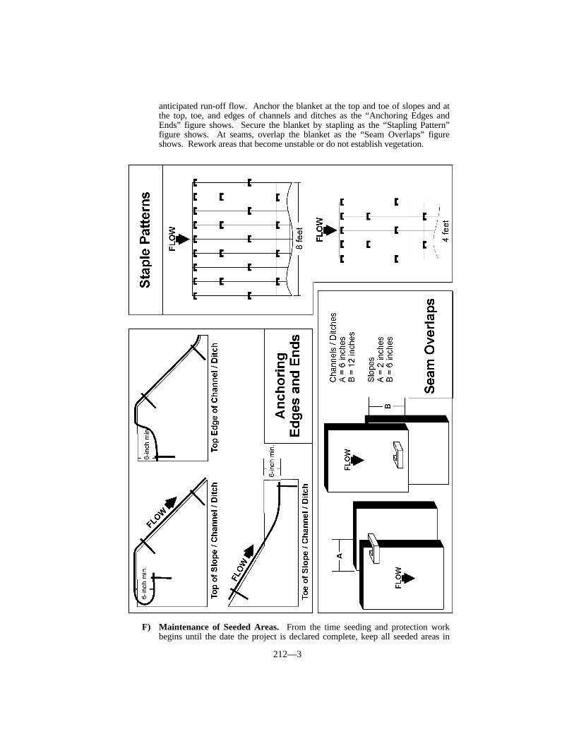
212—3
anticipated run-off flow. Anchor the blanket at the top and toe of slopes and atthe top, toe, and edges of channels and ditches as the “Anchoring Edges andEnds” figure shows. Secure the blanket by stapling as the “Stapling Pattern”figure shows. At seams, overlap the blanket as the “Seam Overlaps” figureshows. Rework areas that become unstable or do not establish vegetation.
F) Maintenance of Seeded Areas. From the time seeding and protection workbegins until the date the project is declared complete, keep all seeded areas in

212—4
good condition at all times. Promptly repair any damage to seeded areas or tomulch materials as directed. Mow when the Engineer directs.
G) Acceptance of Seeding. The Engineer will make an inspection to determine theacceptability of the seeding between 3 and 6 months after completion of theproject. The Engineer may delay the inspection when conditions are such that theacceptability of the seeding cannot be determined at the end of the 6-monthperiod. Ensure that at least 90 percent of each seeded area has a minimum of1,350 live seedlings per square yard at the time of inspection, representative ofthe specified seed mixture with no vacant areas larger than 25 square yards.Also, ensure that all applicable areas have a minimum of 9 live area seedlingsper square yard of crown vetch. Conform to this requirement for all permanentseeding performed in conjunction with the project regardless of the type ofprotection used or the season in which the seeding is performed.
When seeding does not conform to the live seedling requirements at the timeof inspection, submit a corrective work plan to the Engineer for approval andperform the additional work necessary to conform to the original requirements.The Department reserves the right to specify application rates for agriculturallime, fertilizer, seed, and mulch for corrective seeding.
212.03.04 Sodding. At locations specified in the Contract or by the Engineer,prepare the sod bed, incorporate fertilizer and agricultural limestone as needed and placesod flush with any adjacent seeded or turfed area, pavement, curb, or other structures.
The Engineer will make an inspection to determine the acceptability of the sodbetween 3 and 6 months after completion of the project. Ensure that at least 90 percent isalive with no area of dead sod larger than one square yard.
212.04 MEASUREMENT.
212.04.01 Brush Barriers. The Department will not measure the quantity of brushbarriers for payment and will consider construction of brush barriers incidental to Clearingand Grubbing.
212.04.02 Topsoil Furnished and Placed. The Department will measure thequantity in cubic yards in the vehicle at the point of delivery.
212.04.03 Spreading Stockpiled Topsoil. The Department will measure thequantity in cubic yards by taking cross sections of stockpiles immediately before spreadingoperations, and taking final cross sections of the stockpile area after spreading has beencompleted and the area neatly dressed.
When electing to place the topsoil directly without stockpiling, according toSubsection 204.03.07 B), then the Engineer will not separately measure the topsoil notstockpiled.
212.04.04 Agricultural Limestone. The Department will not measure the quantityof agricultural limestone for payment and will consider it incidental to Seeding andProtection and Sodding.
212.04.05 Fertilizer. The Department will not measure the fertilizer used in theseeding or sodding operations for payment and will consider it incidental to these items ofwork.
The Engineer will measure the fertilizer used for top dressing in tons. The Engineerwill weigh top dressing according to Section 109.
212.04.06 Seeding and Protection. The Department will measure the quantity insquare yards.
The Department will include in the quantity any seeding and protection necessary dueto catastrophic events that are beyond the control of the Contractor.
212—5
The Department will not measure any corrective work required to conform toSubsection 212.03.03 F).
The Department will not measure seeding and protection of areas unnecessarilydisturbed or disturbed areas outside the limits of construction.
212.04.07 Erosion Control Blanket. The Department will measure the quantity ofErosion Control Blanket by the square yard of surface covered. The Department will notmeasure seeding for payment and will consider it incidental to the Erosion ControlBlanket. The Department will not measure any reworking of slopes, channels, or ditchesfor payment as it is considered corrective work and incidental to the Erosion ControlBlanket.
212.04.08 Sodding. The Department will measure the quantity in square yards. TheDepartment will not measure any additional sod necessary to restore areas that fail toconform to the original requirements.
212.04.09 Crown Vetch. The Department will measure the quantity in square yards.
212.04.10 Mowing. When mowing is required, the Department will measure andpay for the quantities under a supplemental agreement.
212.05 PAYMENT. The Department will pay for the completed and acceptedquantities under the following:
Code Pay Item Pay Unit5997 Topsoil Furnished and Placed Cubic Yard5998 Spreading Stockpiled Topsoil Cubic Yard5966 Topdressing Fertilizer Ton5985 Seeding and Protection Square Yard5950 Erosion Control Blanket Square Yard5989 Special Seeding Crown Vetch Square Yard5990 Sodding Square Yard
The Department will consider payment as full compensation for all work requiredunder this section.
213—1
SECTION 213 WATER POLLUTION CONTROL
213.01 DESCRIPTION. Control water pollution through use of berms, dikes, dams,sediment basins, fiber mats, netting, gravel, mulches, grasses, slope drains, and othererosion control devices or methods. Coordinate these measures with the permanenterosion control features specified in Section 212 and the Contract to the extent practical toensure effective and continuous erosion control throughout the construction and postconstruction period.
213.02 MATERIALS. Conform to Section 827.
213.03 CONSTRUCTION. Conform to the applicable provisions of KRS Chapters220 and 224 of the State Water Pollution Control Laws and other applicable statutesrelating to the prevention or abatement of water pollution. Conform to the requirements ofall Federal and State agencies having jurisdictional control over the land the project isconstructed through. Secure all necessary permits from the appropriate agencies for anytemporary stream crossings and for waste area sites in flood plains, when the crossingsand sites are not designated on the Plans.
Exercise every reasonable precaution to prevent the pollution of streams, lakes, andreservoirs. Construct all permanent drainage structures, ditch checks, and paved ditches assoon as practical. Conduct and schedule operations to avoid the muddying or siltation ofstreams, lakes, and reservoirs and to avoid damage to fish habitats. While work on anitem is suspended, do not leave the partially completed item in a manner that willcontribute to erosion.
Construct water pollution controls in stream channels only in areas where channelchanges or channel clearings are specified in the Plans or where necessary for temporary orpermanent structures. Do not divert water through channel changes until the specifiedchannel lining has been constructed or placed, unless there is no alternative in thejudgment of the Engineer.
Do not place material removed from the roadway or channel changes in streams,stream channels, other areas subject to flooding, or other locations where it may be washedaway by high stream flows or fast runoff. Do not place harmful materials where they maybe carried into a stream or into underground water at any time.
Provide temporary bridges or structures for hauling materials across streams. Do notoperate mechanized equipment in streams except as required for the construction ofstructures and channel changes, or for clearing channels.
Keep clearing of stream side trees to the absolute minimum necessary for theconstruction of the project.
When materials known to produce pollutants are encountered, excavate, place, cover,or otherwise deter the material as a potential pollutant according to the Contract and as theEngineer directs.
Do not disturb lands and waters outside the limits of the construction. Before finalacceptance of the work, reshape all such disturbed areas, including abandoned haul roads,storage areas, and plant sites, to conform to the adjacent ground.
213.03.01 Best Management Practices (BMP). Prepare the BMP jointly with theEngineer before the Preconstruction Conference. Include erosion control for all off right ofway work. Plan to trap at least 80 percent of the sediment generated by the constructionactivities. Ensure that the BMP provides one-inch of ponding per 2 1/2 acres of soildisturbance. Achieve this ponding with silt checks, silt traps, and sedimentation basins.Reduce the ponding requirement by appropriately timing construction of sodded andaggregate lined ditches, silt fences, and other provisions used to slow the water down or byperforming progressive seeding, mulch covering, or other provisions used to reduce thesoil exposure.
Ensure that the BMP is available for public inspection throughout the life of theproject.
213—2
213.03.02 Progress Requirements. Coordinate the progress of both permanent andtemporary erosion control measures with the clearing, grubbing, and grading operationsthroughout the duration of the project, and according to the BMP.
The Engineer will limit the area of excavation, borrow, and embankment operationscommensurate with the Contractor’s capability of maintaining the finish grading, seeding,and other such permanent pollution control measures according to the accepted schedule.For areas greater than 750,000 square feet submit a written request for approval to theEngineer. Keep the duration of the exposure of the uncompleted construction as short aspractical.
After exposing areas of erodible material, make every effort to stabilize and protect theareas as quickly as possible. Upon failure to coordinate the erosion control measures withthe grading operations in a manner to effectively control erosion and to prevent waterpollution, the Engineer will suspend the grading operations and withhold monies due oncurrent estimates until all aspects of the work are coordinated in an acceptable manner.Additionally, the Department will apply a penalty equal to the liquidated damages whenall aspects of the work are not coordinated in an acceptable manner within 5 days afterwritten notification.
In case of repeated failures to control erosion, pollution, or siltation, the Engineerreserves the right to employ outside assistance or use his own forces to provide thenecessary corrective measures. The Department will charge such incurred direct costs plusproject engineering costs to the Contractor and make appropriate deductions from the payestimate.
213.03.03 Inspection and Maintenance. Investigate all erosion control devicesweekly and after each 0.1-inch rainfall event. Remove all accumulated silt when thedevices are 50 percent full.
The Engineer will monitor the in-place erosion control for the project once every 7calendar days and within 24 hours following a 0.1-inch or greater rainfall. The Engineerwill furnish the documentation of this monitoring and any proposed changes due to thismonitoring to the Contractor. This documentation and any proposed changes are to beincluded with the Erosion Control Schedule.
213.03.04 Construction Activities Affecting Streams. When in-stream work isunavoidable, perform it in a manner and duration to minimize re-suspension of sedimentsand disturbance to substrates and bank or riparian vegetation. To the maximum extentpractical, perform all work during low flow conditions. Investigate for water in-takes orother activities immediately downstream affected by increased turbidity resulting from thework. Before beginning any work in the stream, give sufficient notice to allow thedownstream water users to prepare for any temporary change in water quality.
Use fill or riprap that will not adversely affect the biological, chemical or physicalproperties of the receiving waters or cause violations of water quality standards. Whenriprap or channel lining is installed, use a weight and size that will not create bank stressor slump conditions.
On channel slopes not riprapped or otherwise stabilized, re-vegetate stream banks andriparian zones concurrently with Project progression to restore beneficial wildlife habitat.When specified in the Contract, randomly place, in offset rows, trees and shrubs asspecified in the Plans; on either one side or both sides of the channel bank; and upstreamand downstream of a proposed bridge within the disturbed area as specified in the Plans.Limit each species to 20 percent of the total. The Contract will specify the seeds, shrubs,and trees and include a quantity to be selected from each category. The Plans will includethe rate of seeding. The Department may allow an adjustment in the plant species andquantities based on field conditions.
Do not dump spoil materials from the watercourse or on-shore operations, includingsludge deposits, into the watercourse according to Section 404 guidelines of the CleanWater Act. Provide areas of deposit of dredged materials with temporary dikes orbulkheads for separation and retention of settleable solids.

213—3
When specified in the Plans, place soil excavated from an existing channel atdesignated locations along the new channel. This, and any stockpiling or double handlingnecessary is considered incidental to the earthwork bid items on the project.
Carry out the fill created by the discharge and any disposition of dredged or excavatedmaterials on-shore, and all earthwork operations to control and minimize sediment run offand soil erosion to the watercourse.
Place all permanent structures in the stream to allow fish movement through the site.When specified in the Plans, construct artificial riffle structures, flow deflectors, boulders,or other types of structures to replace in stream aquatic habitat.
213.03.05 Temporary Control Measures. Provide and maintain immediatepermanent or temporary pollution control measures to prevent contamination of adjacentproperty, watercourses, lakes, ponds, or other areas of water impoundment.
Incorporate all permanent erosion control features into the project at the earliestpractical time as outlined in the accepted schedule. Provide inlet and outlet protection atexisting drainage structures. Install temporary controls as needed through the duration ofthe project. Coordinate the temporary pollution control measures with the permanenterosion control features to the extent deemed practical by the Engineer to ensure effectiveand continuous erosion control throughout the construction and post-construction periods.
Temporary pollution controls may include construction work outside the right-of-waywhere such work is necessary as a result of roadway construction such as borrow pitoperations, haul roads, and equipment storage sites.
A) Sedimentation Basins. As the first grading operation in the drainage area,construct an earth, or rock and earth, dam with designated spillways according tothe Plans. When a sedimentation basin is to be used and plans are not includedin the Contract, submit plans to the Engineer for approval before construction.
Either clean out and dress or remove the sedimentation basin, as theEngineer directs, upon completion of the project.
B) Silt Checks. Use one of the following types:
1) Silt Check Type I - Straw bales, staked to remain in place.2) Silt Check Type II - Crushed stone such as cyclopean stone riprap, quarry
run stone, or other size material approved by the Engineer, dumped in placeand shaped to the configuration required.
3) Silt Check Type III - Blasted or broken rock dumped in place and shaped tothe configuration required.
Remove and properly dispose of sediment deposited at silt checks asnecessary. When no longer needed, remove the silt checks and dispose ofsurplus materials as excavated materials according to Section 204. Seed andprotect the entire area disturbed, as directed. Do not leave silt checks in placeafter completion of the project unless allowed by the Engineer or specified in thePlans.
C) Silt Traps. Construct silt traps by excavating basins in natural or excavatedchannels. Use one of the following types:
1) Type A - Excavated pits, from 2 to 3 feet in depth, 20 to 30 feet in length,and 5 to 10 feet in width.
2) Type B - Excavated pits with the addition of a dike. Construct according tothe Plans and Standard Drawings
Remove sediment deposited in silt traps. When no longer needed,remove the silt traps and dispose of surplus materials according toSubsection 204.03.08. Seed and protect, or sod, the entire area disturbed, asthe Engineer directs. Do not leave silt traps in place after completion of theproject unless allowed by the Engineer or specified in the Plans.
213—4
D) Temporary Silt Fence. Furnish, install, maintain, and remove temporary siltfence. The temporary silt fence works as a water permeable filter to removesuspended particles from the water passing through it.
Construct as shown in the Contract continuous and transverse to the flow.Limit the equivalent runoff area to 1,000 square feet per 10 feet of temporary siltfence.
Maintain the temporary silt fence after installation. Remove siltaccumulations by tapping the dry fabric from the downstream side and dispose ofit as excavated materials. Replace the geotextile fabric when clogging, damage,or deterioration prevents it from functioning properly.
When no longer needed, remove and dispose of the fence off the right-of-way. Dispose of the accumulated silt or dress in place, and seed and protect thearea. When intact, the Department will allow the reuse of the fence at otherlocations.
E) Temporary Silt Ditch. Construct a special temporary ditch adjacent andparallel to the right-of-way in relatively rolling areas where, in the judgment ofthe Engineer, adjacent property may be damaged from sheet-type soil erosion.This special ditch is not intended to carry large volumes of water but to catchsediment from runoff. Construct silt checks within the ditch or at the outlet.Construct the special ditch according to the Plans and Standard Drawings at thelocations designated by the Engineer.
F) Temporary Seeding and Protection. Obtain the Engineer’s approval for theseed before use.
Promptly perform the work of temporary seeding and protection to preventvisible erosion. Protect all seeded areas with a mulch that precludes siltation.
Perform temporary seeding and protection under the following conditions:
1) When it is impractical to bring an area to final line, grade, and finish so thatpermanent seeding and protection work can be performed withoutsubsequent serious disturbance by additional grading.
2) When soil erosion occurs, or is considered to be a potential problem, onareas where construction operations are temporarily suspended.
3) When an immediate cover would be desirable to minimize erosion, siltation,or pollution.
4) On temporary roadways that are expected to remain in place for longer than30 days and that are constructed of erodible materials.
G) Temporary Mulch. Obtain the Engineer’s approval for the mulch before use.When Temporary Seeding and Protection would be required, but the time of
exposure is 30 days or less, perform the work of temporary mulching to preventvisible erosion. Place temporary mulch to an approximate 2-inch loose depth andapply tackifier.
H) Temporary Drainageways. As erodible areas are exposed, construct temporarydrainageways where needed to divert runoff from erosive soil areas to the silttraps or checks or silt ditches. Construct interceptor ditches or silt fences at thetop of cut slopes when beginning excavation. Construct surface ditches, roadsideditches, and flumes to carry runoff from the roadway at the earliest possible timeduring the grading work.
When needed, use pipe as liners for these temporary drainageways. TheEngineer will approve the type and location of the drainageways as well as theneed for a liner. Install the pipe liner according to the Plans and StandardDrawings. Use pipe of any substantial type or material for overflow pipe in theconstruction of temporary silt basins and for flumes.
When fill slopes have been constructed to such a stage that protection of theface of the slope from roadway runoff is necessary, construct a temporary earthmound ditch or silt fence at the outer edge of the shoulder along the top of the
213—5
embankment as directed by the Engineer. Construct the ditch to form an earthmound on the embankment side of the ditch and carry runoff from the roadwayalong the shoulder to the flumes and roadside ditches. Use temporary bermditches at the top of fill slopes after completing the permanent seeding andprotection work and until beginning the surfacing operations. Stabilize the ditchand mound by spraying with asphaltic material when deemed necessary.
213.04 MEASUREMENT. The Department will consider the various materials andlabor used to construct, maintain, and, when no longer needed, remove the erosion controldevices incidental to the initial construction.
The Department will not measure maintenance or corrective work for payment when itis due to a failure in following the BMP.
213.04.01 Roadway Excavation. The Department will measure the quantityaccording to Subsection 204.04.
213.04.02 Borrow Excavation. The Department will measure the quantityaccording to Subsection 205.04.
213.04.03 Embankment-in-Place. The Department will measure the quantityaccording to Subsection 206.04.
213.04.04 Temporary Seeding and Protection. The Department will measure thequantity in square yards. The Department will not measure temporary erosion andpollution control measures required due to negligence, carelessness, or failure to installpermanent controls as a part of the work as scheduled. When construction of a temporaryroadway is required by the Contract, the Department will measure the associatedtemporary seeding and protection. The Department will not measure temporary seedingand protection of temporary roadways constructed for the convenience of the Contractor.
213.04.05 Temporary Mulch. The Department will measure the quantity in squareyards. The Department will not measure temporary erosion and pollution control measuresrequired due to negligence, carelessness, or failure to install permanent controls as a partof the work as scheduled. When construction of a temporary roadway is required by theContract, the Department will measure the associated temporary mulch. The Departmentwill not measure temporary mulch for temporary roadways constructed for the convenienceof the Contractor.
213.04.06 Pipe for Flumes. The Department will measure the quantity in linearfeet.
213.04.07 Sedimentation Basin. The Department will measure the quantity in cubicyards. The Department will not measure filter pipe, drain pipe, and spillway paving onsedimentation basins for payment and will consider them incidental to this item of work.
213.04.08 Clean Sedimentation Basin. The Department will measure the quantityof sediment removed in cubic yards.
213.04.09 Silt Trap, Type. The Department will measure the quantity by eachindividual unit.
213.04.10 Clean Silt Trap, Type. The Department will measure the quantity byeach individual unit.
213.04.11 Silt Check. The Department will measure the quantity by each individualunit.
213—6
213.04.12 Clean Silt Check. The Department will measure the quantity by eachindividual unit.
213.04.13 Temporary Silt Fence. The Department will measure the quantity inlinear feet from end post to end post of each installation.
213.04.14 Clean Temporary Silt Fence. The Department will measure quantity inlinear feet along the fence.
213.04.15 Temporary Silt Ditch. The Department will measure the quantity asroadway excavation.
213.04.16 Temporary Drainageways. The Department will measure the quantityas roadway excavation.
213.04.17 Channel Lining, Classes IA, II, III, and IV. The Department willmeasure the quantity according to Subsection 703.04.
213.04.18 Plants, Trees, Vines, and Shrubs. The Department will measure thequantity by each individual unit.
213.04.19 Deflector, Gabion. The Department will measure the quantity by eachindividual unit.
213.04.20 Deflector, Dumped Stone. The Department will measure the quantity byeach individual unit.
213.04.21 Riffle Structure, Dumped Stone. The Department will measure thequantity by each individual unit.
213.04.22 Riffle Structure, Gabion. The Department will measure the quantity byeach individual unit.
213.04.23 Boulder. The Department will measure the quantity by each individualunit.
213.05 PAYMENT. The Department will make payment for the completed andaccepted quantities under the following:
Code Pay Item Pay Unit5985 Seeding and Protection See Subsection 212.052200 Roadway Excavation See Subsection 204.052210 Borrow Excavation See Subsection 205.052230 Embankment-in-Place See Subsection 206.055953 Temporary Seeding and Protection Square Yard5952 Temporary Mulch Square Yard---- Pipe for Flumes Linear Foot2711 Sedimentation Basin Cubic Yard2712 Clean Sedimentation Basin Cubic Yard2703, 2704 Silt Trap, Type Each2706, 2707 Clean Silt Trap, Type Each2705 Silt Check Each2708 Clean Silt Check Each2701 Temporary Silt Fence Linear Foot2709 Clean Temporary Silt Fence Linear Foot2482-2484, 2488 Channel Lining, Classes IA, II, III, and IV See Subsection 703.05---- Plants, Vines, and Shrubs See Subsection 724.05

213—7
---- Trees See Subsection 724.052618 Deflector, Gabion Each2617 Deflector, Dumped Stone Each2738 Riffle Structure, Dumped Stone Each2622 Riffle Structure, Gabion Each2713 Boulder Each
The Department will consider payment as full compensation for all work requiredunder this section.

214—1
SECTION 214 GEOTEXTILE CONSTRUCTION
214.01 DESCRIPTION. Install geotextile fabric, when required in the Contract, forslope protection and channel lining, underdrains and drainage blankets, and subgrade orembankment foundation stabilization.
214.02 MATERIALS.
214.02.01 Geotextile Fabric. Conform to Section 843.
214.02.02 Steel Pins. Conform to Section 843.
214.03 CONSTRUCTION. The Engineer will reject the fabric if it has defects, rips,holes, flaws, deterioration, or damage.
Prepare the surface to receive the fabric to a smooth condition, free of obstructions,debris, or sharp objects that may puncture the fabric. Place the fabric smooth and free oftension, stress, folds, wrinkles, or creases. Do not operate equipment directly on the fabric.Protect the fabric at all times from contamination. Remove and replace any contaminatedfabric with uncontaminated fabric.
Repair or replace any fabric damaged. Repair individual isolated cuts, tears, orpunctures by placing a patch of geotextile fabric that extends at least 3 feet beyond thedamage in all directions or by field splicing the patch.
Cover the fabric with a layer of the specified material within 14 calendar days.Remove and replace fabric not covered within the 14 days.
214.03.01 Laps. When more than one strip is necessary, place an overlap of at least18 inches. Place transverse laps so the upstream strip laps over the downstream strip.Place horizontal laps so the upper strip laps over the lower strip.
Install fastener pins through both strips of overlapped fabric at no less than 5-footintervals along a line through the midpoint of the overlap, and at any other locations asnecessary to prevent any slippage of the fabric.
The Department will allow field splices in place of laps.
214.03.02 Field Splices. Sew the full length of the boundary between adjacentsheets of fabric. Ensure that the seam strength conforms to the requirements of Section843.
214.03.03 Slope Protection and Channel Lining. Place Type I fabric with the longdimension parallel to the channel or toe of slope.
Protect the fabric from damage due to the placement of the slope protection or channellining either by limiting the height of drop of the material to no greater than 3 feet or byplacing a cushioning layer of sand on top of the fabric before dumping the material.Demonstrate to the Engineer that the placement technique prevents damage to the fabric.Begin placement of material at the toe and proceed up the slope.
214.03.04 Underdrains. Place and shape Type II fabric to the sides and bottom ofthe trench without stretching the fabric. Place filter aggregate so as not to damage,displace, or dislodge the fabric according to Subsection 704.03. Fold the fabric over thebackfilled trench and secured it with steel pins at intervals of 5 feet to produce a doublethickness of fabric over the top of the trench.
214.03.05 Subgrade or Embankment Foundation Stabilization. Place Type IIIfabric with the long dimension parallel to the long dimension of the area to be covered.Leave surface vegetation in place.
During back dumping and spreading, do not allow the wheels of trucks, dozer blades,and other equipment to come into direct contact with the fabric. Spread the material in the
214—2
direction of the fabric overlap. If large fabric wrinkles develop during spreadingoperations, fold and flatten the wrinkles in the direction of spreading. Avoid large foldswhich reduce the fabric overlap width.
214.03.06 Drainage Blankets. Place Type IV fabric with the long dimensionparallel to the long dimension of the area to be covered.
Place the drainage blanket material to present a reasonably even surface free frommounds or depressions. After the material is placed, fold the fabric over the ends andsides of the material, and place additional fabric over the material so that the material iscompletely encased within the fabric. Install additional pins, regardless of the location, asnecessary to prevent any slippage of the fabric. Place the fabric so that laps do not occur atthe edges or ends of the drainage blanket. Place embankment in a manner to avoiddamage or displacement of the completed drainage blanket.
214.04 MEASUREMENT. The Department will measure the quantity in square yards.The Department will not measure fabric when the Contract indicates the fabric isincidental to the work or when the specification for another item requires incidentalinstallation of geotextile fabric.
The Department will not measure material in laps or seams.When fabric is used for underdrains, either to wrap perforated pipe or to wrap
aggregate, the Department will measure the quantity according to Subsection 704.04.When the fabric is used to completely enclose an aggregate drainage blanket, the
Department will measure the quantity as the sum of (1) the area of the lower surface of theaggregate layer, (2) the area of the upper surface of the aggregate layer, and (3) the area ofthe sides and ends of the aggregate layer; using the dimensions specified in the Plans.
The Department will not measure for payment the repair or replacement of damagedfabric or replacement of fabric not covered within 14 days.
214.05 PAYMENT. The Department will make payment for the completed andaccepted quantities under the following:
Code Pay Item Pay Unit2596-2599 Fabric-Geotextile, Type Square Yard
The Department will consider payment as full compensation for all work requiredunder this section.
215—1
SECTION 215 TREATMENT OF OPEN SINKHOLES
215.01 DESCRIPTION. Clean and fill open sinkholes and cap open sinkholes notused for drainage.
215.02 MATERIALS.
215.02.01 Geotextile Fabric. Conform to Section 843, Type IV.
215.02.02 Concrete. Use Class B concrete conforming to Subsection 601.02 and601.03.
215.02.03 Steel Reinforcement. Conform to Section 811.
215.03 CONSTRUCTION. Locate and flag all open sinkholes before starting clearingand grubbing operations. Clear the sinkhole area according to Section 202. Remove thesoil overburden, organic material, and debris from the sinkhole as specified in the Plans oras directed by the Engineer.
Place geotextile fabric between any soil and the Granular Embankment Refill. Refillthe sinkhole with Granular Embankment, and compact it as the Engineer directs. FurnishGranular Embankment refill conforming to the following requirements:
A) Roadway Excavation. When obtaining granular embankment from roadwayexcavation, the Engineer will accept it by visual inspection. Use granularembankment that is free of shale or other deleterious materials.
B) Off-Site Materials. Use granular embankment having no more than 10 percentpassing the No. 200 sieve when tested according to KM 64-606. The Engineer willinspect the quality of all granular embankments. The Engineer will accept theprocessed material by visual inspection when the material includes a significantamount of fragments greater than 1 1/2 inches. Do not use natural sand and other fineaggregates. The Engineer will approve the size and type of refill.
C) Clay. For clay soil cap, use an impervious clay the Engineer approves. Compactaccording to Section 206.03.03.
D) Concrete. Use a cap of reinforced concrete, precast or cast-in-place, with a minimumthickness of one foot as specified in the Contract or as the Engineer directs. UseClass B concrete according to Subsection 601.03. Furnish precast concrete accordingto Section 605. Reinforce the concrete with No. 8 bars placed on one-foot centers inboth directions, and located 3 inches from the bottom surface of the concrete.Interlock the concrete cap with bedrock.
215.04 MEASUREMENT.
215.04.01 Granular Embankment. When the material is available within the right-of-way, the Department will consider granular embankment used for refill incidental toroadway excavation or embankment-in-place. When material within the right-of-way isunacceptable for refill, the Department will measure the quantity in cubic yards asGranular Embankment.
215.04.02 Clay Soil Cap. The Department will not measure the clay soil cap as aseparate item of work and will consider it incidental to roadway excavation orembankment-in place.
215.04.03 Geotextile Fabric. The Department will measure the quantity accordingto Subsection 214.04.
215.04.04 Concrete, Class B. The Department will measure the quantity according

215—2
to Subsection 601.04.
215.04.05 Cleaning Sinkhole. The Department will measure the quantity by eachindividual unit cleaned.
215.04.06 Steel Reinforcement. The Department will measure the quantityaccording to Subsection 602.04.
215.05 PAYMENT. The Department will make payment for the completed andaccepted quantities under the following:
Code Pay Item Pay Unit2223 Granular Embankment Cubic Yard2596-2599 Geotextile Fabric, Type See Subsection 214.052555 Concrete, Class B See Subsection 601.052469 Clean Sinkhole Each8150 Steel Reinforcement See Section 602.05
The Department will consider payment as full compensation for all work requiredunder this section.
216—1
SECTION 216 SETTLEMENT PLATFORMS
216.01 DESCRIPTION. Furnish all materials, construction, installation, andmaintenance of settlement platforms as the Engineer directs.
216.02 MATERIALS.
216.02.01 Miscellaneous Metals. Conform to Section 813.
216.02.02 Fine Aggregate. Conform to Section 804.
216.02.03 Steel Pipe. The Engineer will visually inspect for acceptance.
216.03 CONSTRUCTION. Fabricate from the materials and to the dimensionsspecified in the Plans or Standard Drawing for settlement platforms.
Level the ground surface to an elevation 2 inches below the desired elevation of thebase plate of the settlement platform. Level over a sufficient area to accommodate thebottom plate and at the location shown or directed. Place, lightly tamp, and level a 2-inchlayer of fine aggregate at the proposed location of the bottom plate. Set and level thebottom plate on the fine aggregate. Place loose soil to an elevation corresponding to that ofthe top plate of the settlement platform. Ensure that the loose soil does not disturb theplatform and that it extends laterally from the perimeter of the top plate to a slope of 1:1 orflatter. After placing and leveling the top plate, complete the embankment as specified forthe project, and ensure that the settlement platform is not damaged or disturbed.
The Engineer will measure and record settlement, to the nearest 0.01 foot, andelevation of the embankment at weekly intervals or more frequently in order that no morethan 10 percent of the expected settlement occurs between readings. The Engineer willsubmit the data to the Division of Materials weekly.
Stop work at any location where settlement platforms are disturbed or damaged, andmake necessary repairs or replacement. As the embankment is constructed, add sectionsof 2 1/2-inch and 4-inch pipe to the assembly (tighten each new section of 2 1/2-inch pipewith a pipe wrench before taking a reading to ensure that the next added section does notaffect future readings). Keep the top of the outer pipe closed as work progresses with a 4-inch standard cap. When work is complete, secure the cap to the final outer pipe section.
216.04 MEASUREMENT.
216.04.01 Settlement Platforms. The Department will measure the quantity byeach individual unit.
216.04.02 Steel Pipe. The Department will measure each size in linear feet.
216.05 PAYMENT. The Department will make payment for the completed andaccepted quantities under the following:
Code Pay Item Pay Unit2692 Settlement Platform Each3340 Steel Pipe, 2 1/2-inch Linear Foot3343 Steel Pipe, 4-inch Linear Foot
The Department will consider payment as full compensation for all work requiredunder this section.

DIVISION 300
AGGREGATE BASE COURSES


301—1
SECTION 301 TRAFFIC-BOUND BASE
301.01 DESCRIPTION. Construct traffic-bound base courses with one or morecourses of coarse aggregate on a prepared subgrade.
When the Contract provides for traffic-bound surfacing of road approaches, privateentrances, and turnouts in conjunction with other highway surfacing or paving operations,perform such work according to Section 112.
301.02 MATERIALS. Furnish aggregate conforming to Section 805.
301.03 CONSTRUCTION.
301.03.01 Preparation of Subgrade. Prepare and maintain the subgrade accordingto Section 207.
301.03.02 Placing Aggregates. Spread the aggregate in the number of courses andat the rate of application indicated in the Contract to the width and depth specified. Placeadditional aggregate to strengthen weakened areas as the Engineer directs.
When practical, route hauling equipment uniformly over all portions of the previouslylaid courses of the base. The Department will not require any additional compaction. Obtain the Engineer’s permission prior to revising this procedure for distribution ofaggregate.
301.04 MEASUREMENT. The Department will measure the quantity in tonsaccording to Section 109.
301.05 PAYMENT. The Department will make payment for the completed andaccepted quantities under the following:
Code Pay Item Pay Unit0020 Traffic-Bound Base Ton
The Department will consider payment as full compensation for all work requiredunder this section.

302—1
SECTION 302 — DENSE GRADED AGGREGATE BASE (DGA)AND CRUSHED STONE BASE (CSB)
302.01 DESCRIPTION. Construct the base on a prepared subgrade.
302.02 MATERIALS.
302.02.01 Aggregate. Conform to Section 805.
302.02.02 Water. Conform to Section 803.
302.02.03 Mixer. Equip the mixer with a water flow system with a positive cut-offcontrol that will stop the flow of water simultaneously with any stoppage in the flow ofaggregate and with valves or other devices that can be easily reset when a change in therate of flow is desired.
302.03 CONSTRUCTION. Prepare the subgrade according to Section 207, and keep itfree from irregularities.
When reshaping and compacting or scarifying and reshaping is not specified forexisting traffic-bound surfaces, grade and shape to the grade and cross section required.
Construct shoulders according to Section 209.
302.03.01 Mixing. Thoroughly mix the aggregate and water in a pugmill type mixer,unless another type mixer is approved. Add water as needed to compact to the specifiedin-place density.
302.03.02 Transporting. Transport the plant-mixed material to the project withoutloss or segregation. Cover each truck load with a heavy canvas sheet to reduce the loss ofmoisture during transit when the time between loading the truck and spreading the mixtureexceeds 30 minutes.
302.03.03 Placing and Spreading. Place and shape the mixture by powerequipment, to the specified lines, grades, cross sections, and depths, without segregation.
Place, spread, shape, and compact in a manner that is as continuous as practicalduring each day’s run. Wet the base as directed during shaping and compactionoperations to maintain the moisture content at the level necessary to ensure propercompaction.
When the required thickness of base is no more than 8 inches for CSB and 6 1/2inches for DGA and the Engineer is satisfied that acceptable compaction can be achievedthroughout the full depth, place the material in one layer. Otherwise, place the material in2 or more layers of no less than 3 inches.
Wet the subgrade or previous base layer as directed before placing the base material.
302.03.04 Compacting.
A) Control Strips. Before constructing the base, complete a control strip todetermine the level of compaction necessary to achieve the target density for theremaining base course. Construct additional control strips whenever a change ismade in the source, gradation, type of subgrade, type of base aggregate, layerthickness, or as the Engineer requires.
Compact with an effort greater than or equal to that produced by a 16-tonpneumatic roller, or a 8-ton steel-wheel vibratory roller. Operate vibratory rollersaccording to the manufacturer’s instructions.
302—2
Leave each control strip in place to become part of the project. Complete atleast one control strip for each layer of base material. Unless the Engineerapproves otherwise, construct the control strip to a minimum length of 500 feetand to the full width of the aggregate base course. Use the same equipment andprocedures intended for the construction of the remainder of the base course. After 2 passes of the compaction equipment the Department will mark and take 3density measurements at randomly selected sites, at least 2 feet from the edge ofthe base. The Department will take density measurements at the same 3locations after subsequent passes of the compaction equipment. Compact thecontrol strip until no further increase in density can be obtained from additionalpasses.
The Engineer will visually inspect the base material after each pass todetermine if the aggregate is being crushed into fine material. If the aggregateis being crushed, cracked, shoved, or shows other signs of distress, ceasecompaction efforts. If compaction of the base is not satisfactory, use othermethods to achieve satisfactory results.
Regardless of lift thickness, the Department will require a control strip toestablish a roller pattern.
B) Target Density. After completing compaction of the control strip, the Engineerwill conduct 10 field density measurements at random locations in the controlstrip and average the 10 measurements to obtain the target density for thecompaction of the base.
C) Field Density Measurement. When the total compacted thickness is more than4 inches, the Engineer will determine the field density with nuclear gauges. When the total compacted thickness is 4 inches or less, the Engineer willdetermine compaction by nuclear gauge or make acceptance by visual inspection.
D) Test Sections. The Engineer will divide the remaining length of the project intotest sections of approximately 2,500 square yards with a depth equal to that of thecontrol strip; divide each test section into 5 equal segments; take densitymeasurements at a random location within each segment; and require the testsections average density to be 98 percent of the target density or greater with noindividual measurement less than 95 percent of the target density.
When the average density of a test section does not meet the density requiredabove, cease laydown operations, and either provide additional compaction effortor rework the entire test section to obtain the required average density. When anindividual density measurement does not meet the required density, provideadditional compaction efforts or rework the area represented by that measurementto meet the required density.
E) General. Maintain the initial layers of base to a uniform grade and cross sectionduring compaction. Shape the final layer with additional material whennecessary.
When trimming the final layer to the final grade with an automatic gradingmachine, provide a layer approximately 1/2 to one inch above grade forcontinuous cutting. After making the final pass with the grading machine, wetand roll the base with a static roller. The Engineer will recheck density to ensurethe material still conforms to the density requirements. Reuse excess materialremoved by the grading machine in shoulders, islands, or other areas whereaggregate stone base is specified, but not under roadway pavement.
Use manually operated mechanical tampers in areas inaccessible to powerequipment.
Do not add fines to meet target density.
302.03.05 Maintenance and Protection. Restrict traffic on the completed base tothe minimum necessary to complete the work, and maintain public traffic. Moisten areassubjected to traffic, as directed, to avoid the loss of fine materials. If desired, use a diluteemulsified asphalt for dust control.
302—3
Before constructing succeeding courses, check for damage, such as raveling and lostdensity, and recheck the grade and cross section. Make corrections as necessary.
Make every reasonable effort to completely cover the aggregate base course with thespecified pavement courses before suspending work for the winter months. When the basecourse is not completely covered with the specified pavement courses, determine andperform all work necessary to protect and maintain the uncompleted work during thewinter months. Perform all work necessary to acceptably repair or restore the uncompletedwork before the beginning of spring paving operations. Obtain the Engineer’s approval forall work necessary to protect, maintain, and repair the base.
302.03.06 Surface Tolerances. Ensure that the surface of the top course of the baseis smooth and uniform. When performing final grading, trim the base to within ± 1/2 inchof the specified cross section and ± 3/8 inch in 10 feet from the specified longitudinalgrade at any location or to an accuracy allowing the succeeding courses to meet theirspecified surface and thickness tolerances, whichever is stricter.
Furnish all devices and labor necessary to check the surface.
302.04 MEASUREMENT. The Department will not measure water used to moistenthe subgrade, for mixing the base material, and to maintain moisture during compactionand maintenance of the base for payment.
The Department will measure the quantity of plant-mixed materials according toSection 109. The Department will not make deductions for water in the mixture.
The Department will not measure construction of control strips, any necessaryreworking of control strips, or test sections for additional payment.
The Department will not measure dust control for payment.The Department will not measure for payment any extra materials, methods, or
construction techniques, the Engineer determines not to be a part of the specifiedconstruction, to protect, maintain, or repair any portion of the uncompleted work during thewinter months.
The Department will measure and deduct material wasted from trimming the finalgrade.
302.04.01 Dense Aggregate Base. The Department will measure the quantity intons.
302.04.02 Crushed Stone Base. The Department will measure the quantity in tons.
302.05 PAYMENT. The Department will pay for the completed and acceptedquantities under the following:
Code Pay Item Pay Unit0001 DGA Base Ton0003 Crushed Stone Base Ton
The Department will consider payment as full compensation for all work requiredunder this section.
303—1
SECTION 303 PAVEMENT DRAINAGE BLANKET
303.01 DESCRIPTION. This section covers pavement drainage blankets. For JPCpavements, construct either an untreated, asphalt-treated, or cement-treated drainageblanket. For asphalt pavements, construct an untreated, asphalt-treated, or cement-treateddrainage blanket as the Contract specifies.
303.02 MATERIALS.
303.02.01 Aggregate. Use crushed stone conforming to Sections 804 and 805.
302.02.02 Asphalt Binder. Conform to Section 806, PG 64-22.
303.02.03 Cement. Conform to Section 801, Type I or III.
303.02.04 Water-Reducing Admixture. Conform to Subsection 802.01, Type A,D, F, or G.
303.02.05 Water. Conform to Section 803.
303.02.06 Curing Compound. Conform to Subsection 823.02.
303.03 CONSTRUCTION.
303.03.01 Composition.
A) Untreated. Provide Size No. 57 aggregate. Obtain the Engineer’s approval forany adjustments to the gradation when increased stability of the drainage blanketis deemed necessary.
B) Asphalt-Treated Drainage Blanket (ATDB). Use a gradation within themaster range in the following table:
Sieve Size Percent Passing1 1/2 inch 1003/4 inch 85-1001/2 inch 35-65
No. 4 0-20No. 8 0-10
No. 200 0-4
Test gradation according to KM 64-407, KM 64-433, or KM 64-620.For asphalt pavements, use an asphalt binder content of 1.5 to 2.5 percent by
weight of the mixture. For JPC pavements, use an asphalt binder content of 2.5percent or less by weight of the mixture. When using a porous aggregate,increase the asphalt binder content as needed to compensate for asphaltabsorption by the aggregate. Submit aggregate samples and a proposed JMF forapproval according to KM 64-421. Maintain the JMF asphalt binder contentwithin ± 0.5 percentage points as determined according to KM 64-405, KM 64-436, or AASHTO T 308.
Asphalt binder content will be based on visual inspection of the extent theaggregate is coated. The Department will not adjust payment due to adjustmentof the asphalt binder content.
Request adjustments in the JMF gradation if deemed necessary to increasestability of the drainage blanket, providing the revised JMF gradation and asphaltbinder content are maintained within the specified limits.
303—2
C) Cement Treated Mixture. Provide Size No. 57 aggregate. Submit aggregatesamples and a proposed cement content, and the Engineer will perform testing asnecessary to determine if the proposed mix design is acceptable.
For asphalt pavements, ensure the mix design conforms to the following:
1) Minimum compressive strength of 400 psi shall be attained in 72 hours ± 6hours. Determine the compressive strength according to KM 64-305, exceptthe specimen shall remain in the mold until the time of the test.
2) Minimum cement content of 250 pounds per cubic yard.3) Maximum water/cement ratio of 0.37.4) Use a water-reducing admixture.
303.03.02 Placement of Drainage Blanket.
A) Untreated Drainage Blanket. Place with self-propelled equipment to produce asmooth, uniform layer of material ready for compaction. Compact with asmooth-wheel roller to a smooth and uniform surface. Do not use vibratingrollers. Place the drainage blanket on the shoulders with an offset spreader toavoid damaging or displacing the underdrain pipe. Immediately replace any pipethat is damaged by construction or hauling equipment.
B) ATDB. All requirements of Section 403 for asphalt mixtures apply, except asfollows:
1) Maintain the temperatures of the materials and the mixture, in degreesFahrenheit, within the following ranges:
Minimum MaximumAggregate 200 260Asphalt Binder 200 260Mixture at Plant 200 260Mixture When Placed 180 260
2) Avoid excess drainage of the asphalt binder while being stored.3) Compact the ATDB using a smooth-wheel roller. Do not use vibrating
rollers. Avoid over rolling to the extent that aggregate particles are broken.4) The surface of the ATDB shall be smooth and uniform, and shall reasonably
conform to the specified lines, grades, and typical section. The completedATDB shall meet the surface tolerances specified in Subsection 403.03.11for base courses. Perform any corrective work necessary using asphaltmixtures the Engineer approves. The Department will not allow proceduresor mixtures that might produce fine material that would tend to clog orreduce drainage.
5) Allow the ATDB to cure at least 10 hours, or as the Engineer directs, beforeplacing subsequent courses.
C) Cement-Treated Drainage Blanket.
1) Plant, Mixing, and Hauling. Conform to the applicable batch plant, mixingprocedures, and hauling equipment requirements of Section 501 for JPCpavement.
2) Placing and Spreading. Use spreading, consolidation, and finishingequipment that conforms to the requirements of Section 501, or is approvedby the Engineer upon demonstration of satisfactory performance on a teststrip of approximately 3,000 square yards.
3) Compaction. Compact the material with a steel-wheeled, tandem rollerweighing approximately 10 tons, unless the drainage blanket is placed by aslip-form paver and the Engineer determines consolidation is acceptable
303—3
without rolling. Compact within 30 minutes after spreading by completingat least 2 complete coverages of the drainage blanket with the roller. Providesufficient equipment and rollers to ensure that no more than 1.25 hourselapse between the time that water is added to the combined aggregate andcement and the time the final compaction is completed.
4) Curing. Cure by one of the following methods immediately after spreadingand compacting the drainage blanket:
a) Cover the entire surface and exposed edges of the drainage blanket withtransparent or white plastic of at least 4 mils thickness. For asphaltpavements, hold the plastic in place with aggregate or other acceptablemeans for at least 3 days. Immediately repair any damage occurring tothe plastic during the curing period.
b) Membrane-cure according to Subsection 601.03.17 B). For JPCpavements, the Department will waive the curing time requirements.
5) Surface Finish. The surface of the drainage blanket shall be smooth anduniform, and shall reasonably conform to the specified lines, grades, andcross section. Ensure the completed drainage blanket does not show adeviation greater than 1/4 inch from a 10-foot straightedge, and the crossslope does not deviate more than 1/4 inch in 5 feet from the specified crossslope.
6) Perform any corrective work necessary using mixtures the Engineerapproves. The Department will not allow procedures or mixtures that mightproduce fine material that would tend to clog or reduce drainage.
7) Weather Limitations and Protection. Mix and place the cement treatedmaterial when the air temperature in the shade, away from artificial heat, is45 °F and rising. Unless otherwise authorized in writing by the Engineer,discontinue mixing and placing the cement-treated material when adescending air temperature in the shade, and away from artificial heat,reaches 50 °F.
303.03.03 Maintenance and Protection. Limit traffic over the drainage blanket tothe minimum necessary for succeeding or adjacent work. Prevent contamination of thedrainage blanket by dust, dirt, or mud. Remove and replace portions of the blanket that iscontaminated to the extent that the drainage is clogged or reduced at no additional cost tothe Department.
Preserve the integrity of the subgrade, base courses, perforated pipe, pavementdrainage blanket, and the subsequent paving courses. Control the gross weights and typesof hauling vehicles so no component is damaged by hauling for construction of the nextcomponent.
Do not operate trucks or other equipment longitudinally directly over the perforatedpipe.
Repair damage to any of the various items, except damage caused by public traffic, atno cost to the Department.
303.03.04 Overlaying of Drainage Blankets. Exercise extreme caution whenplacing asphalt mixtures near or over underdrains to avoid displacing or damaging thedrain.
A) Untreated Drainage Blanket.
1) Asphalt Mixture Overlay. Operate one or more rollers on the drainageblanket ahead of the paver to repair and recompact any portion of thedrainage blanket displaced by hauling equipment. Grade when necessary.Place the first course using a paver mounted on tracks to minimizedisplacement of the drainage blanket.

303—4
Compact the first course of asphalt base placed on an untreateddrainage blanket to the greatest extent possible without damage in thejudgment of the Engineer. The Department will waive density requirementsfor this course. The Department will apply density requirements to allsubsequent courses of asphalt mixture.
Contrary to Section 403, use the rate of application to control thicknessof the asphalt base. Place the mixture at the weight per square yarddesignated in the plans or proposal, or by the Engineer. Do not exceed thedesignated rate of application by more than 5 percent. The Department willnot pay for any material placed in excess of this 5 percent tolerance.
Allow the first course of base 7 days to cure before placing thesucceeding course, unless the Engineer shortens the required time due torainy and/or cool weather. In all cases, provide at least 3 days curing.
2) JPC Overlay. When JPC pavement is constructed on an untreated drainageblanket, place by the slip form process. Use offset equipment to constructJPC shoulders.
B) Treated Drainage Blanket.
1) Asphalt Mixture Overlay. When asphalt pavement is constructed on atreated drainage blanket, place the first course using a paver mounted ontracks if rubber-tired pavers cause displacement of the drainage blanket.
Compact asphalt base according to Subsection 403.03.10.Allow the first course of asphalt mixture to cure overnight before placing
the succeeding course.Place the thickness of asphalt base on treated drainage blankets
according to Subsection 403.03.06.2) JPC Pavement Overlay. Place without damaging the drainage blanket or
underdrain system. Use anchor hooks of sufficient length to extend throughthe drainage blanket and hold the load-transfer assemblies securely in place.
303.04 MEASUREMENT.
303.04.01 Drainage Blanket-Type I (Untreated). The Department will measure thequantity in tons according to Section 109.
303.04.02 Drainage Blanket-Type II (ATDB). The Department will measure thequantity in tons according to Subsection 402.04. Asphalt mixtures used for leveling thesurface of the completed drainage blanket will be measured in tons as drainage blanket.
303.04.03 Drainage Blanket-Type III (Cement-Treated). The Department willmeasure the quantity in tons according to Section 109.
303.04.04 JPC Pavement Drainage Blanket. The Department will measure thequantity in tons according to Section 109.
303.05 PAYMENT. The Department will pay for the completed and acceptedquantities under the following:
Code Pay Item Pay Unit0015 Drainage Blanket-Type I - Untreated Ton0018 Drainage Blanket-Type II - Asphalt Treated Ton0019 Drainage Blanket-Type III - Cement Treated Ton0022 JPC Pavement Drainage Blanket Ton
The Department will make payment for Drainage Blanket-Type II (ATDB) accordingto the Lot Pay Adjustment Schedule for Specialty Mixtures in Section 404.
The Department will consider payment as full compensation for all work required

303—5
under this section.

DIVISION 400
ASPHALT PAVEMENTS

401—1
SECTION 401 ASPHALT PLANT REQUIREMENTS
401.01 DESCRIPTION. Provide and maintain a plant and all equipment necessary toproduce and test asphalt mixtures.
401.02 EQUIPMENT.
401.02.01 All Asphalt Mixing Plants. Ensure that all asphalt mixing plants areinspected and approved by the Department before initial use and a minimum of onceannually thereafter. For initial approval, submit a “Contractor’s Master Certification ofAsphalt Mixing Plant and Related Equipment” form for each plant to the Engineer. Forpreviously approved plants, submit an “Annual Renewal Certification for PreviouslyApproved Plants and Related Equipment” form to the Engineer before beginning eachseason. When significant changes are made in the plant equipment or in the method ofoperation at an approved plant, reapply for approval.
Ensure the manufacturer’s plate, listing the maximum capacity of the plant, isattached to the plant. Do not operate the plant at a production rate greater than theoperational capacity of any plant component. The Engineer reserves the right to reduce thesize of the batch or rate of production when, in his judgment, the mixer will not operateeffectively at the rated capacity. Operate the plant so that it produces a mixture within thespecified properties, gradation tolerances, and asphalt binder tolerances.
When plants are in operation, the Department will require the following minimumcomputer equipment for submission of test data: one computer on the site of operationsinstalled with, and capable of running, the following:
1) Microsoft Windows 95; and2) Microsoft Excel, Version 7.0 or greater.
Additionally, the Department will require that each Company provide at least oneInternet access site for sending and receiving electronic mail.
A) Field Laboratory. Furnish and maintain a field laboratory facility according toSubsection 106.03.02. A field laboratory may be a building, trailer, or spacewithin a building, provided the space is completely closed to the remainder of thebuilding. Provide means for visually monitoring mixing plant operations. Do notuse laboratories for storage.
Provide a laboratory inspected and qualified according to the Department’sQuality Assurance Program for Materials Testing and Acceptance andconforming to the following minimum requirements:
1) a floor space of 250 square feet with a minimum width of 7 feet;2) provisions for heating and cooling within the range of 65 to 80 °F;3) adequate lighting; and4) a sufficient number of electric wall outlets (110-120v) to accommodate all
equipment.
The Engineer will accept a laboratory with a floor space less than 250square feet if it was previously approved and is determined to be of adequatesize.
In addition to the equipment required to perform testing according to theAASHTO standards and Kentucky Methods (KM), equip each laboratory withthe following minimum furnishings and equipment, conforming to the applicablespecifications, as required for the type of construction specified in the Contract:
1) one workbench, at least 2.5 feet wide by 6 feet long;
401—2
2) one desk or table and 2 chairs;3) a fire extinguisher located near the door; and4) a first-aid kit.
When solvent extractions are used for acceptance purposes, provide alladditionally needed equipment, according to the applicable KM. Ensure that theextractor stand is fully enclosed and equipped with fans capable of exhausting atleast 1,450 cubic feet per minute. Build duct-work across the entire backside ofthe workbench with an access port into an enclosed cabinet, so as to direct anyfumes or dust from the top of the workbench into the enclosed cabinet. TheEngineer will furnish a sketch of an acceptable exhaust system upon request. TheEngineer will approve other configurations if he determines that they meet theintended purpose. Mount all control switches outside the cabinet.
When using solvent extractions for asphalt binder content determination,provide equipment and solvent for either the centrifuge (Method A) or thevacuum extractor (Method B) according to KM 64-405.
B) Aggregate Storage. Provide sufficient storage for separate stockpiles, bins, orstalls for each size of aggregate; or otherwise provide a direct feed from theaggregate production. Keep different sizes separated until delivery through thecold feed proportioning devices. Maintain the storage area in an orderlycondition with walkways between stockpiles not separated by bins or stalls.Provide adequate provisions for sampling aggregates from the stockpiles or thedirect feed from the aggregate production.
C) Equipment for Handling Asphalt Binders. Provide tanks for storage ofasphalt binders equipped for heating the material to the temperature required inSubsection 401.03.01. Heat the tank without letting the flames contact it.
Provide a circulating system for the asphalt binder of a capacity that ensurescontinuous circulation between the storage tank and proportioning unit duringthe entire operating period.
Place the discharge end of the asphalt binder circulating pipe at the oppositeend of the circulating pump, near the bottom of the storage tank.
Heat and insulate all pipelines and fittings to prevent heat loss.Provide a storage tank with a capacity that ensures continuous plant
operation and uniform temperature of the asphalt binder when it is introducedinto the pugmill. Provide means for accurately measuring the volume of asphaltbinder in the storage tank at any time. Provide separate storage for each type andgrade of asphalt binder stored at each plant site.
Provide a sampling outlet that is readily accessible and free from obstructionin each storage tank or in the asphalt binder feed lines connecting the plantstorage tanks to the asphalt plant. When the sampling valve is located in the feedline, provide it between the pump and the return line discharge in a location thatis readily accessible and free from obstruction. Provide a drainage receptacle forflushing the outlet before sampling.
D) Feeder for Drier. Provide a mechanical feeder that is an apron, belt,reciprocating plate, or vibrating type with accurate and separate adjustments fortotal and proportional feed. Install total and proportional feed adjustments thatare continuously variable and capable of being fixed in any position.
E) Drier. Provide a drier capable of drying and heating the aggregate to themoisture content and temperature requirements set forth in the applicable mixturespecifications without leaving any visible unburned residue on the aggregatewhen discharged from the drier.
F) Screens. Provide plant screens to prevent oversized material and to separate allaggregates so they may be recombined consistently within the specification limitsfor the asphalt mixture being produced.
G) Bins. Provide the plant, except for drum-mix plants, with a hot-bin storage of asufficient capacity to ensure uniform and continuous operation.
Use bins that are divided into at least 3 compartments and arranged to
401—3
ensure storage of appropriate fractions of the aggregates. Use bins that aredesigned such that samples of dry, screened aggregates may be readily sampledfrom each compartment.
Provide each compartment with an overflow pipe that prevents material frombacking up into other bins or into contact with the screen.
Provide dry storage for mineral filler and provisions for accurateproportioning.
Equip each compartment with an audible alarm to indicate when there is alow supply of material. Equip batch plants with an actuating device thatprevents material from being drawn from other compartments when material islow in the compartment being used. Equip continuous plants with an actuatingdevice that prevents material from being drawn from all compartments whenmaterial is low in any one compartment.
H) Asphalt Binder Control Unit. Provide a means, either by weighing ormetering, to obtain the proper quantity of asphalt binder. Ensure that meteringdevices are accurate to within ± 1.0 percent when tested for accuracy. Useasphalt binder scales that conform to Subsection 401.02.02 B).
When metering the quantity of asphalt binder, check the delivery of themeter by actual weight.
For drum and continuous mixing plants, calibrate the asphalt binder deliverysystem and metering device before starting production at the beginning of eachconstruction season, each time the plant is relocated, after making significantchanges in the plant equipment, after revising the method of operation, andwhenever the Engineer deems it necessary.
Maintain the specified temperatures of asphalt binder in the pipelines,meters, buckets, spray bars, and other containers or flow lines.
I) Recordation. Provide an automatic graphic or digital record of the productionquantities according to AASHTO M 156.
J) Thermometers. Provide a recording and a non-recording thermometer in theasphalt binder feed line between the storage tank and the charging valve. Whena non-recording thermometer is installed in the asphalt binder storage tank(s), theDepartment will not require a non-recording thermometer in the feed line.
Provide a recording and a non-recording thermometer near the discharge ofthe aggregate bin, unless the aggregate dryer is equipped with an automaticburner control system capable of heating the aggregate and consistentlymaintaining the temperature of the asphalt mixture within ± 15 °F.
K) Control of Mixing Time. Use a plant equipped with means for governingmixing time.
L) Dust Collectors. Equip the plant with an effective dust collector capable ofeither wasting the collected dust or using it in the mixture.
M) Power Sprayer. Furnish a power sprayer to apply a fine uniform spray or mistof approved material in truck beds to prevent the adherence of asphalt mixturesduring hauling.
N) Signs. Place a sign on or near the plant visible to all asphalt mixture haulersprior to loading, stating “TRUCKS HAULING STATE MATERIAL WILL NOTBE LOADED WHEN BEDS CONTAIN CONTAMINATING MATERIALAND MUST BE TARPED PRIOR TO LEAVING PLANT.”
O) Other Requirements. Provide adequate and safe stairways to the mixerplatform and guarded ladders for other plant units at all locations necessary toprovide access to all plant operations. Provide a sturdy platform of sufficientheight to inspect and sample the mixture after discharge into the haul units.
P) Safety Requirements. Ensure that all plants and plant sites conform to thesafety, health, and sanitation requirements of Subsection 107.01.01.
401.02.02 Special Requirements for Batch Plants.
A) Weigh Box or Hopper. Provide equipment that weighs each bin size of
401—4
aggregate into a weigh box or hopper that is suspended on scales and holds a fullbatch size of aggregate. Provide gates that prevent leakage when closed.
B) Scales. Provide springless, dial type, or other approved types of scales for anyweigh box or hopper, and for weighing asphalt material. Provide scales ofstandard make and design having tolerances on overregistration andunderregistration not exceeding 0.5 percent of the indicated weight when testedfor accuracy.
Ensure that the change in load required to noticeably alter the position of restof the indicating element(s) of a non-automatic indicating scale is not greaterthan 0.1 percent of the nominal scale capacity.
Ensure that graduation intervals for scales are less than 0.1 percent of thenominal scale capacity and are plainly visible.
On dial scales, reduce parallax effects to the practical minimum withclearance between the indicator index and scale graduations not exceeding 0.06inches.
Provide scales equipped with adjustable set points or pointers for markingthe weight of each material to be weighed into the batch.
Have the component batching scales inspected and certified as specified inSubsection 109.01.02.
Provide no fewer than 10 test weights, each of at least 50 pounds nominalweight and stamped with its actual weight, for the purpose of testing andcalibrating the scales. For each scale, provide a suitable cradle or platform forapplying test loads. Keep test weights clean and conveniently located forcalibration of the scale or provide means for testing and calibrating the scales bya commercial scale company when the Engineer requests.
The Department will allow batch plants to operate with no screens, otherthan a scalper screen, provided:
1) The plant is equipped with an aggregate weighing device (belt scales)that provide positive weight control;
2) The system controls aggregate flow from each bin;3) The system controls the proportion from each bin in relation to the total
aggregate flow;4) The system provides the plant operator with a continuous digital display
of the flow rate from each bin and the total aggregate flow rate; and5) The system provides an alarm or automatic shut-off on the aggregate
feed that operates when the flow from any individual feeder isinterrupted.
Calibrate each cold feeder, along with the aggregate weighing devices,according to Subsection 401.02.05 A) and B).
C) Bins. For batch plants equipped with aggregate weighing devices Subsection401.02.02 B) specifies, the Department will not require 3 separate hot aggregatebin compartments.
D) Asphalt Materials Bucket. If using a bucket, provide one large enough tohandle a batch in a single weighing.
Provide a filling system that prevents asphalt binder material fromoverflowing, splashing, or spilling outside the bucket during filling andweighing.
Use a steam or oil-jacketed bucket or a bucket with properly insulatedelectric heating units. Arrange the bucket so it delivers the asphalt binder in athin uniform sheet or in multiple sprays over the full length of the mixer.
E) Mixer Unit for Batch Method. Include at the plant a batch mixer of anapproved twin pugmill type. Ensure that the mixer does not leak or causesegregation during discharge.
Provide a blade clearance from all fixed and moving parts that does not
401—5
exceed 1 1/2 inches.Provide a mixer with an accurate time lock. Control the operation of a
complete mixer cycle by locking the weigh-box gate after charging the mixeruntil closing of the mixer gates at the completion of the cycle. Ensure that theasphalt materials bucket remains locked throughout the dry-mixing period andthat the mixer gates remain locked throughout the dry and wet mixing periods.(The dry-mixing period is the interval of time between the opening of the weigh-box gate and the application of asphalt binder. The wet-mixing period is theinterval of time between the start of the application of asphalt binder and theopening of the mixer gate.)
401.02.03 Special Requirements for Automatic Batching. Provide the systemswith equipment for accurately proportioning batches of the various components of themixture by weight in the proper sequence and for controlling the sequence and timing ofmixing operations. Equip the plant with adjustable timing devices and other time-delaycircuits that integrate the individual components of batching and mixing operations withthe auxiliary interlock cut-off circuits necessary to interrupt and stop the automatic cyclingof the batching operations whenever the quantity of any ingredient falls outside thetolerance specified below:
Ensure that the accumulated weight of the batches is within 2.0 percent of the totalbatch weight. Record batch quantities according to AASHTO M 156.
When the automatic proportioning system becomes inoperative, the Engineer mayallow the plant to operate semi-automatically until repairs can reasonably be expected tobe made, provided the asphalt mixtures produced conform to specifications. TheDepartment will not allow the plant to operate in this manner for more than 3 workingdays.
401.02.04 Special Requirements for Continuous Plants.
A) Gradation Control Unit. Provide a means to check the proportioning of eachbin size of aggregate by weight.
Mount interlocked feeders under the bin compartments. Equip theinterlocked feeders with a dust-proof revolution counter with maximumgraduations of 0.1 of a revolution. Set the bin proportions based on pounds ofeach aggregate size per revolution.
Provide each bin with a feeder mechanism capable of controlling the rate offlow of aggregate from each bin. If a gate orifice feeder is used, ensure that it hasat least one adjustable dimension. Provide calibrated gages with graduations ofno more than 0.1 inch for each gate to establish the gate openings.
When using mineral filler, furnish a separate bin and feeder with its driveinterlocked with the aggregate feeders.
B) Weight Calibration of Asphalt Binder and Aggregate Feed. Calibrate thegate openings and asphalt materials flow by means of test samples in pounds perrevolution.
Use individual orifices to bypass the aggregate feed out of the bins into
BATCH TOLERANCESPercent of Total
Material Batch WeightsBatch Aggregate Component ± 1.5Mineral Filler ± 0.5Asphalt Binder ± 0.1Zero Return (Aggregate) ± 0.5Zero Return (Asphalt Binder) ± 0.1

401—6
suitable test boxes. Confine each individual material in individual testreceptacles or compartments.
Supply accessories so the aggregate in each compartment may be weighedseparately.
When equipped with aggregate weighing devices (belt scales), calibrateeach cold feeder, along with the aggregate weighing devices, according toSubsection 401.02.05 A) and B).
C) Synchronization of Aggregate and Asphalt Binder Feed. Provide positiveinterlocking or mechanical control between the flow of aggregate through thegates and the flow of asphalt binder through the proportioning device. Check therate of flow of the asphalt binder by the scale weight per revolution.
D) Mixer Unit for Continuous Method. Provide a continuous mixer of anapproved twin pugmill type.
Provide paddles that are adjustable for angular position on the shafts andreversible to retard the flow of the mix.
Equip the hopper with dump gates that allow rapid and complete dischargeof the asphalt mixture.
401.02.05 Special Requirements for Dryer Drum Plants.
A) Aggregate Weighing Device. Provide an aggregate weighing device thatincludes a compensating adjustment for aggregate weight changes due to suchfactors as moisture content, wasting collected fines, and adding mineral filler.Provide a device that is capable of being set to the nearest 0.1 percent. Ensurethe metering devices are accurate to within ± 0.5 percent.
B) Feeder for Drier. Provide a scalping screen of appropriate size in advance ofthe weighing device.
Control aggregate flow from each bin. Control the proportion from each binin relation to the total aggregate flow. Provide the plant operator with acontinuous digital display of the flow rate from each bin and the total aggregateflow rate. When devices other than belt scales are used to control individualaggregate proportions or when belt scales do not have the capability to controlthe proportioning from each bin in relation to the total aggregate flow, provide analarm that operates when the sum of the individual cold feeds differs by morethan 3 percent from the measured weight of the total aggregate feed.
Provide an aggregate feed system with belt scales or other devices to providepositive weight control of the total aggregate feed. Ensure that the totalaggregate flow is automatically coupled with the asphalt binder proportioningdevice.
Provide an alarm or automatic shut-off on the total aggregate feed thatoperates when the flow from any individual feeder or the flow of asphalt binderto the drum is interrupted.
Provide means for obtaining representative samples of individual andcombined aggregate from belts or feeders before their introduction into the dryer.
Calibrate each cold feeder, along with the aggregate weigh bridge(s), beforestarting production at the beginning of each construction season, each time theplant is relocated, after making significant changes in the plant equipment, afterrevising the method of operation, and whenever the Engineer deems necessary.
C) Drier. Use a dryer drum mixer capable of simultaneously heating, mixing, andthoroughly coating the aggregate with a controlled amount of asphalt binder in arotating cylindrical drum. The Department may allow coating of the aggregatewith asphalt binder in a separate chamber with an approved design.
Equip the dryer drum plant with approved thermometric instruments at thedischarge chute of the drum mixer. Equip the system with automatic burnercontrols regulated by approved temperature-sensing devices.
D) Surge and/or Storage Bin. Provide a surge and/or storage bin conforming toSubsection 401.03.02 D).

401—7
E) Dust Collector. Use a dust collector capable of proportioning collected dust inthe vicinity of the asphalt injection device.
F) Production Quality Control. Stop mixing operations immediately if, at anytime, there is a failure of the automatic electronic weighing system of theaggregate feed or the asphalt binder feed control occurs. Do not manuallyoperate the proportioning controls.
401.03 CONSTRUCTION.
401.03.01 Preparation of Mixtures. Deposit the coarse and fine aggregates in thecold elevator(s) at a rate to ensure correct and uniform temperature control of the heatingand drying operations.
If the supplier heats the asphalt binder outside the specified range, let it reach atemperature within the specified range before mixing it with the aggregates. The Engineermay retest or reject asphalt mixture, in storage at the plant, that has been heated by theContractor outside the specified range. Do not use asphalt binder while it is foaming.
Maintain the temperature of the component materials and the asphalt mixture withinthe ranges listed in the following table:
Maintain the temperature of the mixture at the plant to within ± 15 °F of the approvedmixing temperature. The Engineer may accept batches outside this tolerance if they arewithin the temperature requirements listed in the above table.
401.03.02 Mixing and Holding. Measure each size of aggregate and the asphaltbinder separately. Regulate the proportion for each component to produce a mixturewithin the limits of the job-mix formula (JMF) and having all particles coated with asphaltbinder.
Thoroughly mix the hot aggregates at the temperatures specified and proportion themby weight.
The Engineer may establish maximum mixing times when deemed necessary.
A) Batch Plants. Use the following mixing times, unless the Engineer determinesthat longer times are necessary, to produce acceptable mixtures:
1) Three seconds minimum for mixing the dry aggregates, beginning at thetime of the opening of the aggregate weigh hopper discharge gate;
2) Fifteen seconds maximum for introducing asphalt binder in an evendistribution throughout the full length of the mixer, beginning at the end ofthe dry-mixing interval;
3) Twenty-five seconds minimum for mixing the aggregates and asphalt
MIXING AND LAYING TEMPERATURES (°F)
Material Minimum MaximumAggregates 240 330Aggregates used with Recycled Asphalt Pavement (RAP) 240 Asphalt Binders PG 58-22 and PG 64-22 230 330
PG 70-22 285 350PG 76-22 285 350
Asphalt Mixture at Plant PG 58-22 and PG 64-22 250 330(Measured in Truck) PG 70-22 300 350
PG 76-22 310 350Asphalt Mixture at Project PG 58-22 and PG 64-22 230 330(Measured in Truck PG 70-22 275 350 When Discharging) PG 76-22 300 350

401—8
binder, beginning with the start of flow of the asphalt binder to the mixer;4) When the time for introducing the asphalt binder exceeds 10 seconds, mix
the asphalt binder and aggregates, after all asphalt binder has beenintroduced, a minimum of 15 seconds; and
5) Thirty seconds minimum for the total mixing time from the time of theopening of the aggregate weigh hopper discharge gate until the time of theopening of the mixer discharge gate.
When the Engineer extends either the time for dry-mixing or the time forintroducing the asphalt binder into the mixer, or both, extend the minimum totalmixing time to the same lengths of time as the dry-mixing time and asphaltbinder introduction time.
B) Continuous Plants. Mix the aggregates and asphalt binder to produce a wellcoated mixture.
C) Dryer Drum. For a dryer drum mixing plant, the Engineer will not establish themixing time. However, maintain production at the rate required to obtain asatisfactory aggregate coating and a uniform mixture conforming to the mixturespecifications.
D) Surge or Storage Systems. Provided each system has prior approval, theDepartment will allow surge or storage systems for hot asphalt mixtures. TheEngineer will approve the surge or storage system if tests indicate the system iscapable of conveying, retaining, and delivering the asphalt mixture withoutballing or hardening, appreciable loss of mixture temperature, segregation of theaggregates, or excessive oxidation of the asphalt binder. Add a silicone additiveto the asphalt binder for mixtures to be stored beyond the day of mixing. TheEngineer may withdraw approval of a surge or storage system when tests orinspections indicate the system is having a detrimental effect on the asphaltmixture.
Insulate bins intended for storage, and seal the top and bottom of the bins toprevent infiltration of outside air. When using bins for storage, maintain nearfull to provide a non-oxidizing condition. Maintain mixture temperatures towithin those specified for Asphalt Mixtures at Plant according to Subsection401.03 or 404.03 as applicable.
Completely empty surge bins by the end of each working day. When thebins cannot be emptied, store the asphalt mixtures overnight in a manner thatprevents damage. Obtain the Engineer’s approval for storage longer thanovernight, up to 72 hours.
The Engineer will reject any asphalt mixture damaged in any way by use ofa surge or storage system.
401.04 MEASUREMENT. Reserved.
401.05 PAYMENT. Reserved.
402—1
SECTION 402 CONTROL AND ACCEPTANCE OFASPHALT MIXTURES
402.01 DESCRIPTION. Provide the process control and acceptance testing of allclasses and types of asphalt mixtures.
402.02 MATERIALS AND EQUIPMENT.
402.02.01 Personnel. Provide a qualified Superpave Mix Design Technologist(SMDT) to be responsible for the submission and adjustment of the mix designs. Providea qualified Superpave Plant Technologist (SPT) to be present during production and toperform the daily inspection, process-control, and acceptance testing at the plant site.
The Department will use a qualified SMDT for approval of all mix designs and aqualified SPT for verification testing.
402.03 CONSTRUCTION.
402.03.01 Responsibilities.
A) Composition of Mixtures. A JMF is defined as a single percentage for eachspecified sieve size for aggregate gradations and a specified asphalt bindercontent (AC) expressed to the nearest 0.1 percent. The Department will requirean approved JMF within the specified gradation requirements for each mixturerequired on the project. Submit the JMF for the Engineer’s approval according toKM 64-421.
B) Setup. Notify the Engineer of the intent to start a minimum of 36 hours beforebeginning production of each type of mixture. Furnish the facilities, equipment,personnel and all other resources needed to comply with KM 64-435 and KM 64-426. Provide a Quality Control Plan (QCP) and complete the setup duties of KM64-421. Upon completing setup, prepare 2 duplicate maximum specific gravity(Gmm) samples according to KM 64-411, and furnish them to the Engineer beforethe start of the second day of production. Complete the process controloperations of KM 64-426. When the Engineer directs, obtain samples forDepartment use.
C) Process Control. After the setup period, perform the process control operationsof KM 64-426.
402.03.02 Acceptance.
A) General. The Department will accept asphalt mixtures from the plant on a lotbasis. A lot is 4,000 tons. A sublot is 1,000 tons. Monitor and evaluate the AC,air voids (AV), voids-in-mineral aggregate (VMA), density, and gradation. Document and report all acceptance tests on the Asphalt Mixtures AcceptanceWorkbook (AMAW). Submit the completed AMAW for each lot to theDepartment within 5 working days after the completion of the lot.
B) Sampling. Obtain all samples from the truck bed. Excluding the first sublot ofproduction, obtain all samples according to the random sampling procedures ofKM 64-113. Randomly determine when to obtain the acceptance samples, andtake one sample for each sublot. At the beginning of each production day, do nottake any acceptance samples before the production of 50 tons. If the randomnumber falls within the first 50 tons, take the sample from the first loaded truckfollowing the truck containing the 50th ton produced.
C) Setup. The setup period is the first sublot of production. Within the first 4 hoursof project production or by the end of the first sublot, test to document that themixture meets a 0.90 minimum pay value for AC, AV, and VMA. For mixtureswith a total-project quantity between 500 and 1000 tons, perform a minimum of
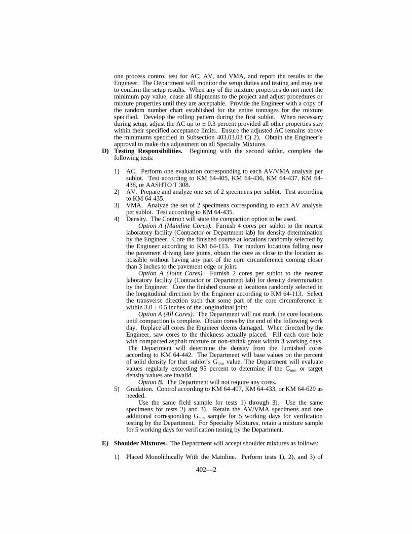
402—2
one process control test for AC, AV, and VMA, and report the results to theEngineer. The Department will monitor the setup duties and testing and may testto confirm the setup results. When any of the mixture properties do not meet theminimum pay value, cease all shipments to the project and adjust procedures ormixture properties until they are acceptable. Provide the Engineer with a copy ofthe random number chart established for the entire tonnages for the mixturespecified. Develop the rolling pattern during the first sublot. When necessaryduring setup, adjust the AC up to ± 0.3 percent provided all other properties staywithin their specified acceptance limits. Ensure the adjusted AC remains abovethe minimums specified in Subsection 403.03.03 C) 2). Obtain the Engineer’sapproval to make this adjustment on all Specialty Mixtures.
D) Testing Responsibilities. Beginning with the second sublot, complete thefollowing tests:
1) AC. Perform one evaluation corresponding to each AV/VMA analysis persublot. Test according to KM 64-405, KM 64-436, KM 64-437, KM 64-438, or AASHTO T 308.
2) AV. Prepare and analyze one set of 2 specimens per sublot. Test accordingto KM 64-435.
3) VMA. Analyze the set of 2 specimens corresponding to each AV analysisper sublot. Test according to KM 64-435.
4) Density. The Contract will state the compaction option to be used.Option A (Mainline Cores). Furnish 4 cores per sublot to the nearest
laboratory facility (Contractor or Department lab) for density determinationby the Engineer. Core the finished course at locations randomly selected bythe Engineer according to KM 64-113. For random locations falling nearthe pavement driving lane joints, obtain the core as close to the location aspossible without having any part of the core circumference coming closerthan 3 inches to the pavement edge or joint.
Option A (Joint Cores). Furnish 2 cores per sublot to the nearestlaboratory facility (Contractor or Department lab) for density determinationby the Engineer. Core the finished course at locations randomly selected inthe longitudinal direction by the Engineer according to KM 64-113. Selectthe transverse direction such that some part of the core circumference iswithin 3.0 ± 0.5 inches of the longitudinal joint.
Option A (All Cores). The Department will not mark the core locationsuntil compaction is complete. Obtain cores by the end of the following workday. Replace all cores the Engineer deems damaged. When directed by theEngineer, saw cores to the thickness actually placed. Fill each core holewith compacted asphalt mixture or non-shrink grout within 3 working days. The Department will determine the density from the furnished coresaccording to KM 64-442. The Department will base values on the percentof solid density for that sublot’s Gmm value. The Department will evaluatevalues regularly exceeding 95 percent to determine if the Gmm or targetdensity values are invalid.
Option B. The Department will not require any cores.5) Gradation. Control according to KM 64-407, KM 64-433, or KM 64-620 as
needed.Use the same field sample for tests 1) through 3). Use the same
specimens for tests 2) and 3). Retain the AV/VMA specimens and oneadditional corresponding Gmm sample for 5 working days for verificationtesting by the Department. For Specialty Mixtures, retain a mixture samplefor 5 working days for verification testing by the Department.
E) Shoulder Mixtures. The Department will accept shoulder mixtures as follows:
1) Placed Monolithically With the Mainline. Perform tests 1), 2), and 3) of

402—3
Part D) above as part of the mainline mixture. Do not take cores from theshoulder for acceptance testing.
2) Placed Separately. Perform tests 1), 2), and 3) of Part D) above.
F) Specialty Mixtures. The Department will accept Open-Graded Friction Course(OGFC), Asphalt-Treated Drainage Blanket (ATDB), Asphalt Mixture forPavement Wedge, Leveling and Wedging, Scratch Course, asphalt mixtures fortemporary applications, and asphalt mixtures for Base Failure Repair as follows. Perform one AC and one gradation determination per sublot. Determine thegradation from samples corresponding to the same production time period as theAC determination. Obtain and test the gradation samples according to KM 64-407, KM 64-433, or KM 64-620.
G) Mixtures With RAP. Furnish the grade of asphalt binder determined accordingto KM 64-427. Furnish a RAP sample and a minimum of 3 representativeextracted gradation and determinations with the mixture design submittal.Perform one AC determination during setup. After setup, perform and documentan AC determination and gradation for every 2 lots of mixture supplied.
H) Unsatisfactory Work.
1) Based on Lab Data. After the setup period, when the Contractor orDepartment determines any individual sublot pay value would be below0.90 for AC or AV in any QC or QA test, make adjustments andimmediately run tests again. If the second round of tests determines anyindividual sublot pay value would have been below 0.90 for AC or AV,cease all shipments to the project and adjust procedures or mixturecomposition until they are acceptable. Document acceptable materials andwork before restarting operations.
When the Contractor or Department determines that the VMA is 1.1 to1.5 percent below the specified minimum value from AASHTO MP2 for thenominal-maximum size of mixture in any QC or QA test, make adjustmentsand immediately run tests again. If the second round of tests determines thatthe VMA is again 1.1 to 1.5 percent below the specified minimum valuefrom AASHTO MP2, cease all shipments to the project. Also, when theContractor or Department determines that the VMA is more than 1.5 percentbelow the specified minimum value from AASHTO MP2 in any QC or QAtest, cease all shipments to the project. Adjust procedures or mixturecomposition until they are acceptable. Document acceptable results andwork before restarting operations.
When the Engineer determines that safety concerns or otherconsiderations prohibit an immediate shutdown, continue work and theDepartment will make an evaluation of acceptability according toSubsection 402.03.04.
2) Based on Field Review. If the Department determines that a portion of in-place material is unsatisfactory, the Department may require that thelocation be cored. The Department will then test the material for AC andDensity. The Department will consider the work unsatisfactory and requirecorrective work to the affected area when a property met or exceeded a 1.00pay value in the sublot acceptance test and the core shows the propertyhaving a pay value of below 0.90. Additionally, the Department willconsider the work unsatisfactory and require corrective work to the affectedarea when any property of the core is within the following thresholds,regardless of the sublot acceptance test results:
PROPERTY THRESHOLD
AC ≥ ± 0.9% deviation from JMF

402—4
Density ≤ 89.0% or ≥ 97.5%
402.03.03 Verification. For volumetric properties, the Department will perform aminimum of one verification test for AC, AV, and VMA for each lot according to thecorresponding procedures as given in Subsection 402.03.02. For specialty mixtures, theDepartment will perform one AC and one gradation determination per lot according to thecorresponding procedures as given in Subsection 402.03.02. However, Departmentpersonnel will not perform AC determinations according to KM 64-405. The Departmentwill obtain an independent sample at the same time the Contractor is obtaining the randomsample. The Department may perform the verification test on the Contractor’s equipmentor on the Department’s equipment. Provided the differences are within the toleranceslisted below and the results compare favorably with the other sublots’ results, theDepartment will use the Contractor’s test values to compute the appropriate lot pay value.
When differences between test results are not within the tolerances listed below, theDepartment will retest the Contractor’s retained samples for the sublots. TheDepartment’s results will be used in the computation of the appropriate Lot PayAdjustment. In the event that the Contractor’s retained samples are not available, theContractor shall provide additional samples, at his expense, as directed by the Engineer, todetermine the acceptability of the lot in question.
The Department will monitor the test results of the acceptance testing for each sublotto identify patterns within the data. When patterns indicate substantial differencesbetween the verified and non-verified sublots, the Department will perform furthercomparative testing according to Subsection 402.03.04.
The Department will perform independent-assurance testing (IAST) at the frequencyprescribed by the Department’s Manual of Field Sampling and Testing Practices.
402.03.04 Dispute Resolution. When differences between the Department andContractor continue to exist and impact acceptability or payment, resolve the disputeaccording to Subsection 113.07.
402.04 MEASUREMENT. The Department will measure asphalt mixtures by the ton.On initial treatment and resurfacing jobs, the Department will not measure material placedin excess of the 5-percent tolerance specified in Subsection 403.03.06.
The Department will not measure for payment any extra materials, methods, orconstruction techniques, determined by the Engineer not to be a part of the specifiedconstruction, used to protect, maintain, or repair any portion of the uncompleted workduring the winter months.
The Department will not measure the filling of core sample holes of asphalt mixturesfor payment and will consider them incidental to the asphalt mixture.
When Reshape and Compact is not listed as a bid item, the Department will notmeasure the preparation of the foundation for the mixture courses.
The Department will not measure anti-strip additive for payment and will consider itincidental to the asphalt mixture.
COMPARISON OF DEPARTMENT AND CONTRACTOR TESTINGTest Tolerance (%)AC ± 0.5
AV and VMA ± 1.0 (same equipment)± 1.5 (different equipment)
1/2 inch and larger ± 53/8 inch, No. 4, No. 8, and No. 16 ± 4
No. 30, No. 50, and No. 100 ± 3No. 200 ± 2

402—5
For initial treatment, the Department will not measure excavation at bridge ends andrelated disposal of materials for payment and will consider it incidental to the asphaltmixture.
The Department will not measure construction of indented rumble strips for paymentand will consider it incidental to the asphalt mixture.
402.04.01 Weight. The Department will weigh asphalt mixtures according toSection 109. The actual weight equals the pay weight except when the aggregates usedhave a combined bulk specific gravity in excess of 2.75. When the combined bulk specificgravity is greater than 2.75, the Department will determine the pay weight according to thefollowing formula:
T = W [%AC + %MF + (%Aggregate x 2.75)/G] / 100
Where:• T = Pay weight.• W = Actual weight.• %AC = Percent, by weight, of asphalt binder in the total mixture.• %Aggregate = Percent, by weight of total mixture, of mineral aggregates
excluding mineral filler.• G = Calculated combined, bulk, oven-dry, specific gravity of aggregates
used in the mixture, excluding mineral filler.• %MF = Percent, by weight, of mineral filler.
The Department will determine the bulk, oven-dry specific gravity for the fine andcoarse aggregates according to AASHTO T 84 and AASHTO T 85, respectively. TheDepartment will determine the frequency of testing for specific gravity of the actual projectaggregates to determine the pay weight.
402.04.02 Thickness on New Construction. When the core thickness exceeds thecompacted plan thickness by more than 1/2 inch, the Department will deduct the thicknessexceeding the 1/2-inch tolerance. When calculating the deduction for excess thickness, theDepartment will not include in the thickness measurements any leveling course placed atthe Contractor’s expense or any materials placed on top of the completed base at thedirection of the Engineer.
When the Engineer determines the asphalt base is deficient in thickness by more than1/2 inch from the compacted plan thickness, the Department will measure materialrequired according to Subsection 403.03.06 B) for the overlay as asphalt base. TheDepartment will only measure the calculated quantity necessary to bring the deficient areato the plan thickness. The Department will not measure material placed in excess of theplan thickness to achieve smooth transitions or to match grades.
If the Engineer deems it necessary to check the thickness of the overlaid area bycoring, the Department will deduct the cost of this additional coring from monies due, or tobecome due, the Contractor when deficient thickness is found.
When the Engineer waives the overlaying requirement, he will make a reduction inpayment for the theoretical quantity of asphalt base as determined deficient.
402.05 PAYMENT.
402.05.01 Specialty Mixtures. The Department will calculate pay for OGFC,ATDB, Asphalt Mixture for Pavement Wedge, Leveling and Wedging, Scratch Course,asphalt mixtures for temporary applications, and asphalt mixtures for Base Failure Repairaccording to the Lot Pay Adjustment Schedule for Specialty Mixtures. The Departmentwill assign a pay value for AC and gradation within each sublot and average the sublotpay values to determine the pay value for each lot.

402—6
402.05.02 Asphalt Mixtures and Mixtures With RAP. The Department will payfor the mixture at the Contract unit bid price and apply a Lot Pay Adjustment for each lotplaced based on the degree of compliance with the specified tolerances. Using theappropriate Lot Pay Adjustment Schedule, the Department will assign a pay value for theapplicable properties within each sublot and average the sublot pay values to determine thepay value for a given property for each lot.
A) First Sublot (Setup). When the Engineer determines the first sublot’s individualpay values are 0.90 or greater, the Department will use 1.00 pay values for allproperties in the sublot. When the Engineer determines any of the first sublot’sindividual pay values are less than 0.90, the Department will apply a pay value of0.85 or less for that property and may require corrective work.
B) After the First Sublot (Setup). The Department will use the Contractor’s testresults for each sublot to determine the pay values for the applicable propertiesprovided the mixture’s values are acceptable according to Subsection 402.03.03. When the Contract specifies compaction Option A, the Department will use theDepartment’s test results for each sublot to determine the pay value for Lane andJoint Density.
When the randomly determined samples for AC, AV, VMA, and gradation(when applicable) fall outside the final sublot, the Department will calculatepayment for these properties using the test results from the previous sublot.
When the final sublot contains a tonnage amount resulting in less than thefull amount of randomly selected cores, the Department will calculate paymentfor Lane and Joint Density using the available test results for the final sublot.
C) Conventional and RAP Mixtures Placed on Shoulders.
1) Placed Monolithically With The Mainline – The Department will pay asmainline mixture but use 1.00 for the Lane and Joint Density Pay Value forshoulder quantities.
2) Placed Separately. The Department will use 1.00 for the Density Pay Value.
D) Conventional and RAP Mixtures Placed Monolithically as AsphaltPavement Wedge. The Department will pay as mainline mixture but use a 1.00pay value for all properties.
E) Asphalt Mixtures for Temporary Pavement. When the Engineer determinesthe individual pay values are 0.90 or greater, the Department will use a 1.00 payvalue for all properties. When the Engineer determines any of the individual payvalues are less than 0.90, the Department will apply a pay value of 0.85 or lessfor that property and may require corrective work.
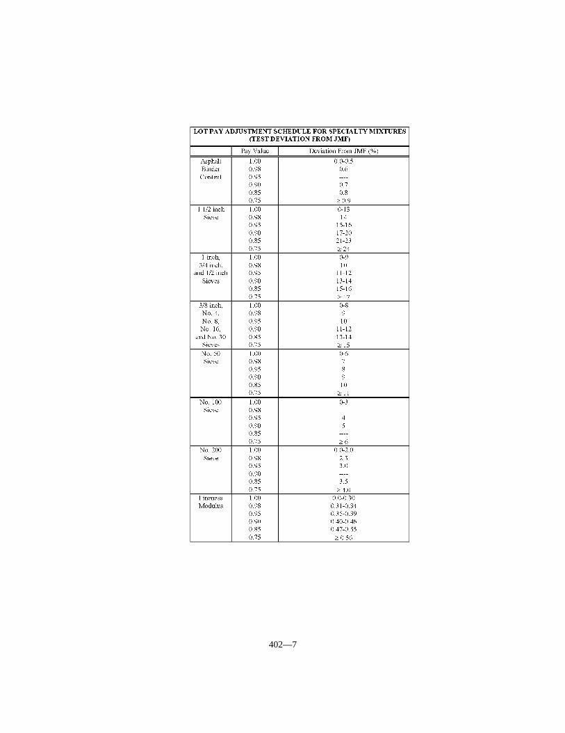
402—7
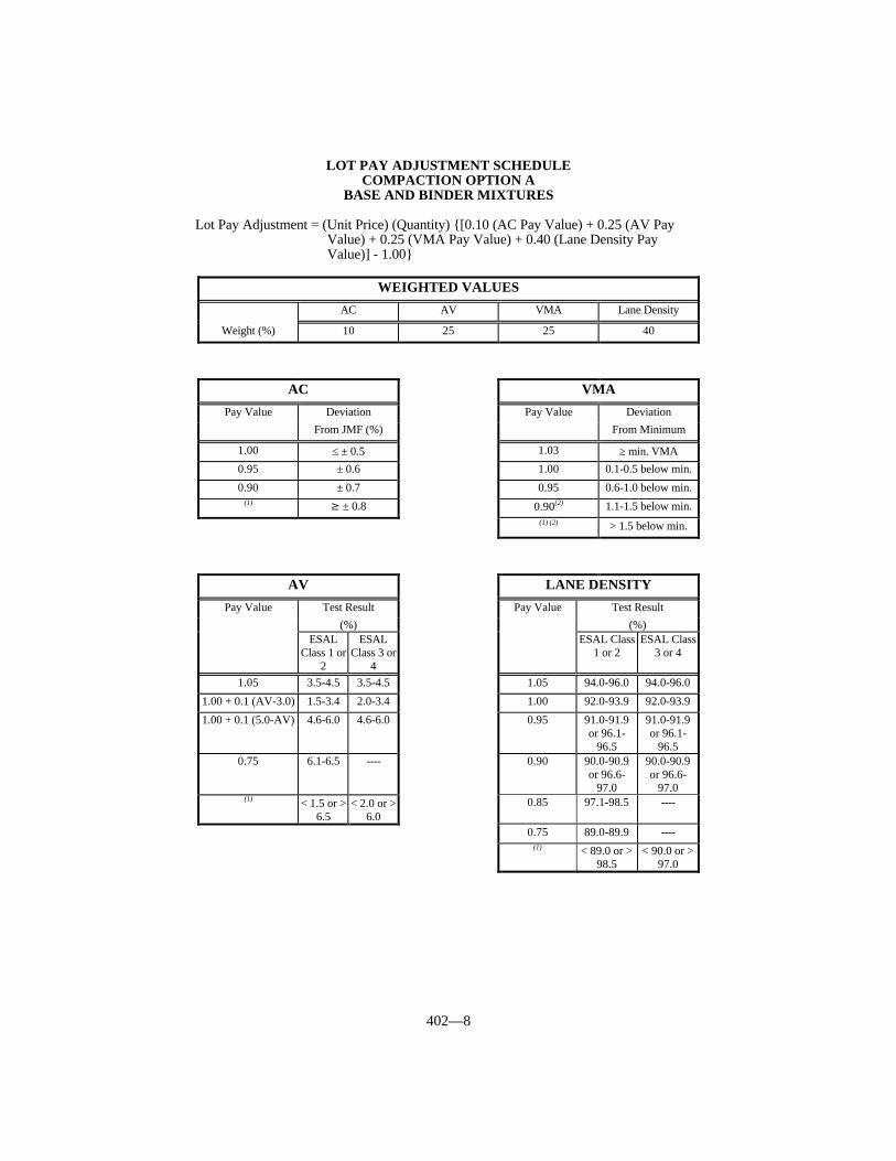
402—8
LOT PAY ADJUSTMENT SCHEDULECOMPACTION OPTION A
BASE AND BINDER MIXTURES
Lot Pay Adjustment = (Unit Price) (Quantity) {[0.10 (AC Pay Value) + 0.25 (AV PayValue) + 0.25 (VMA Pay Value) + 0.40 (Lane Density PayValue)] - 1.00}
WEIGHTED VALUES
AC AV VMA Lane Density
Weight (%) 10 25 25 40
AC VMA
Pay Value Deviation Pay Value DeviationFrom JMF (%) From Minimum
1.00 ≤ ± 0.5 1.03 ≥ min. VMA0.95 ± 0.6 1.00 0.1-0.5 below min.
0.90 ± 0.7 0.95 0.6-1.0 below min.(1) ≥ ± 0.8 0.90(2) 1.1-1.5 below min.
(1) (2) > 1.5 below min.
AV LANE DENSITY
Pay Value Test Result Pay Value Test Result(%) (%)
ESALClass 1 or
2
ESALClass 3 or
4
ESAL Class1 or 2
ESAL Class3 or 4
1.05 3.5-4.5 3.5-4.5 1.05 94.0-96.0 94.0-96.0
1.00 + 0.1 (AV-3.0) 1.5-3.4 2.0-3.4 1.00 92.0-93.9 92.0-93.9
1.00 + 0.1 (5.0-AV) 4.6-6.0 4.6-6.0 0.95 91.0-91.9or 96.1-
96.5
91.0-91.9or 96.1-
96.50.75 6.1-6.5 ---- 0.90 90.0-90.9
or 96.6-97.0
90.0-90.9or 96.6-
97.0(1) < 1.5 or >
6.5< 2.0 or >
6.00.85 97.1-98.5 ----
0.75 89.0-89.9 ----(1) < 89.0 or >
98.5< 90.0 or >
97.0
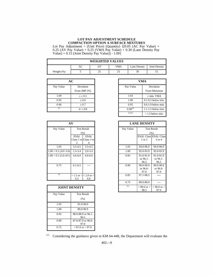
402—9
LOT PAY ADJUSTMENT SCHEDULECOMPACTION OPTION A SURFACE MIXTURES
Lot Pay Adjustment = (Unit Price) (Quantity) {[0.05 (AC Pay Value) +0.25 (AV Pay Value) + 0.25 (VMA Pay Value) + 0.30 (Lane Density PayValue) + 0.15 (Joint Density Pay Value)] - 1.00}
(1) Considering the guidance given in KM 64-448, the Department will evaluate the
WEIGHTED VALUES
AC AV VMA Lane Density Joint Density
Weight (%) 5 25 25 30 15
AC VMA
Pay Value Deviation Pay Value DeviationFrom JMF (%) From Minimum
1.00 ≤ ± 0.5 1.03 ≥ min. VMA0.95 ± 0.6 1.00 0.1-0.5 below min.
0.90 ± 0.7 0.95 0.6-1.0 below min.(1) ≥ ± 0.8 0.90(2) 1.1-1.5 below min.
(1) (2) > 1.5 below min.
AV LANE DENSITY
Pay Value Test Result Pay Value Test Result(%) (%)
ESALClass 1 or
2
ESALClass 3 or
4
ESAL Class1 or 2
ESAL Class3 or 4
1.05 3.5-4.5 3.5-4.5 1.05 94.0-96.0 94.0-96.0
1.00 + 0.1 (AV-3.0) 1.5-3.4 2.0-3.4 1.00 92.0-93.9 92.0-93.9
1.00 + 0.1 (5.0-AV) 4.6-6.0 4.6-6.0 0.95 91.0-91.9or 96.1-
96.5
91.0-91.9or 96.1-
96.50.75 6.1-6.5 ---- 0.90 90.0-90.9
or 96.6-97.0
90.0-90.9or 96.6-
97.0(1) < 1.5 or >
6.5< 2.0 or >
6.00.85 97.1-98.5 ----
0.75 89.0-89.9 ----
JOINT DENSITY (1) < 89.0 or >98.5
< 90.0 or >97.0
Pay Value Test Result
(%)
1.05 91.0-96.0
1.00 89.0-90.9
0.95 88.0-88.9 or 96.1-96.5
0.90 87.0-87.9 or 96.6-97.0
0.75 < 87.0 or > 97.0
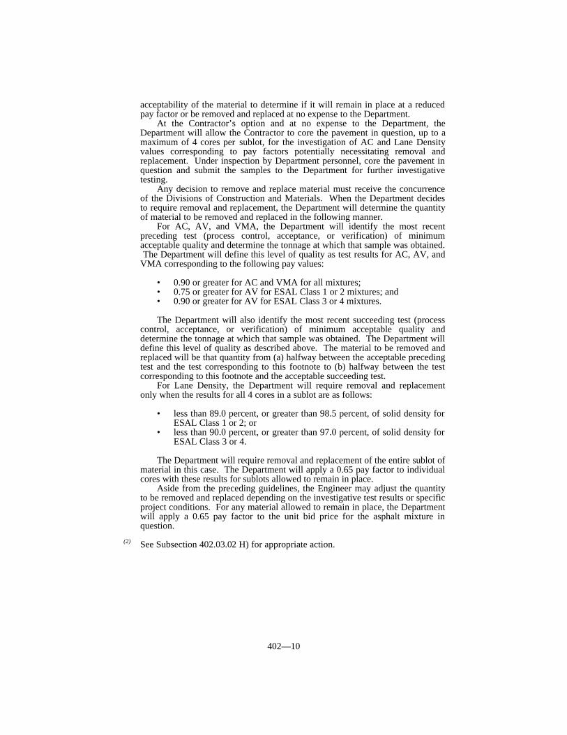
402—10
acceptability of the material to determine if it will remain in place at a reducedpay factor or be removed and replaced at no expense to the Department.
At the Contractor’s option and at no expense to the Department, theDepartment will allow the Contractor to core the pavement in question, up to amaximum of 4 cores per sublot, for the investigation of AC and Lane Densityvalues corresponding to pay factors potentially necessitating removal andreplacement. Under inspection by Department personnel, core the pavement inquestion and submit the samples to the Department for further investigativetesting.
Any decision to remove and replace material must receive the concurrenceof the Divisions of Construction and Materials. When the Department decidesto require removal and replacement, the Department will determine the quantityof material to be removed and replaced in the following manner.
For AC, AV, and VMA, the Department will identify the most recentpreceding test (process control, acceptance, or verification) of minimumacceptable quality and determine the tonnage at which that sample was obtained. The Department will define this level of quality as test results for AC, AV, andVMA corresponding to the following pay values:
• 0.90 or greater for AC and VMA for all mixtures;• 0.75 or greater for AV for ESAL Class 1 or 2 mixtures; and• 0.90 or greater for AV for ESAL Class 3 or 4 mixtures.
The Department will also identify the most recent succeeding test (processcontrol, acceptance, or verification) of minimum acceptable quality anddetermine the tonnage at which that sample was obtained. The Department willdefine this level of quality as described above. The material to be removed andreplaced will be that quantity from (a) halfway between the acceptable precedingtest and the test corresponding to this footnote to (b) halfway between the testcorresponding to this footnote and the acceptable succeeding test.
For Lane Density, the Department will require removal and replacementonly when the results for all 4 cores in a sublot are as follows:
• less than 89.0 percent, or greater than 98.5 percent, of solid density forESAL Class 1 or 2; or
• less than 90.0 percent, or greater than 97.0 percent, of solid density forESAL Class 3 or 4.
The Department will require removal and replacement of the entire sublot ofmaterial in this case. The Department will apply a 0.65 pay factor to individualcores with these results for sublots allowed to remain in place.
Aside from the preceding guidelines, the Engineer may adjust the quantityto be removed and replaced depending on the investigative test results or specificproject conditions. For any material allowed to remain in place, the Departmentwill apply a 0.65 pay factor to the unit bid price for the asphalt mixture inquestion.
(2) See Subsection 402.03.02 H) for appropriate action.
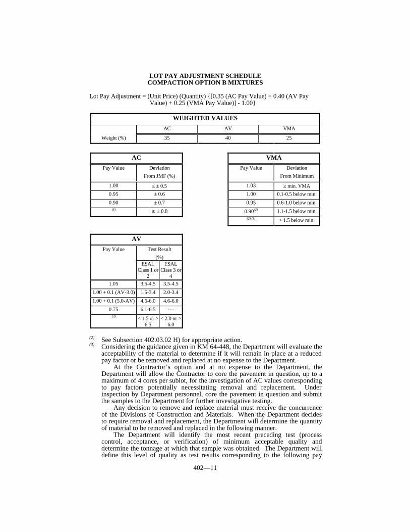
402—11
LOT PAY ADJUSTMENT SCHEDULECOMPACTION OPTION B MIXTURES
Lot Pay Adjustment = (Unit Price) (Quantity) {[0.35 (AC Pay Value) + 0.40 (AV PayValue) + 0.25 (VMA Pay Value)] - 1.00}
(2) See Subsection 402.03.02 H) for appropriate action.(3) Considering the guidance given in KM 64-448, the Department will evaluate the
acceptability of the material to determine if it will remain in place at a reducedpay factor or be removed and replaced at no expense to the Department.
At the Contractor’s option and at no expense to the Department, theDepartment will allow the Contractor to core the pavement in question, up to amaximum of 4 cores per sublot, for the investigation of AC values correspondingto pay factors potentially necessitating removal and replacement. Underinspection by Department personnel, core the pavement in question and submitthe samples to the Department for further investigative testing.
Any decision to remove and replace material must receive the concurrenceof the Divisions of Construction and Materials. When the Department decidesto require removal and replacement, the Department will determine the quantityof material to be removed and replaced in the following manner.
The Department will identify the most recent preceding test (processcontrol, acceptance, or verification) of minimum acceptable quality anddetermine the tonnage at which that sample was obtained. The Department willdefine this level of quality as test results corresponding to the following pay
WEIGHTED VALUES
AC AV VMA
Weight (%) 35 40 25
AC VMA
Pay Value Deviation Pay Value DeviationFrom JMF (%) From Minimum
1.00 ≤ ± 0.5 1.03 ≥ min. VMA0.95 ± 0.6 1.00 0.1-0.5 below min.
0.90 ± 0.7 0.95 0.6-1.0 below min.(3) ≥ ± 0.8 0.90(2) 1.1-1.5 below min.
(2) (3) > 1.5 below min.
AV
Pay Value Test Result(%)
ESALClass 1 or
2
ESALClass 3 or
41.05 3.5-4.5 3.5-4.5
1.00 + 0.1 (AV-3.0) 1.5-3.4 2.0-3.4
1.00 + 0.1 (5.0-AV) 4.6-6.0 4.6-6.0
0.75 6.1-6.5 ----(3) < 1.5 or >
6.5< 2.0 or >
6.0
402—12
values:
• 0.90 or greater for AC and VMA for all mixtures;• 0.75 or greater for AV for ESAL Class 1 or 2 mixtures; and• 0.90 or greater for AV for ESAL Class 3 or 4 mixtures.
The Department will also identify the most recent succeeding test (processcontrol, acceptance, or verification) of minimum acceptable quality anddetermine the tonnage at which that sample was obtained. The Department willdefine this level of quality as described above. The material to be removed andreplaced will be that quantity from (a) halfway between the acceptable precedingtest and the test corresponding to this footnote to (b) halfway between the testcorresponding to this footnote and the acceptable succeeding test.
Aside from the preceding guidelines, the Engineer may adjust the quantityto be removed and replaced depending on the investigative test results or specificproject conditions. For any material allowed to remain in place, the Departmentwill apply a 0.65 pay factor to the unit bid price for the asphalt mixture inquestion.

403—1
SECTION 403 PRODUCTION AND PLACEMENT OFASPHALT MIXTURES
403.01 DESCRIPTION. This section includes general requirements that are applicableto all types of asphalt mixtures. Deviations from these general requirements are indicatedin the specific requirements for each type.
Construct one or more courses of asphalt mixture on the prepared foundationaccording to these Specifications and the specific requirements of the type specified in theContract.
403.02 MATERIALS AND EQUIPMENT.
403.02.01 Fine Aggregate. Conform to Section 804.
403.02.02 Coarse Aggregate. Conform to Section 805.
403.02.03 Asphalt Binder. Conform to Section 806.
403.02.04 Self-Leveling Silicone Rubber Sealant. Conform to Section 807.
403.02.05 Asphalt Release Agent. Provide materials conforming to KM 64-422. Ensure each shipment is accompanied by a certification of conformance.
403.02.06 Transport Equipment. Provide trucks for transporting asphalt mixturesthat have tight, clean, and smooth metal beds that have been sprayed with a minimumamount of release agent. Do not load trucks that are contaminated with an unapprovedrelease agent. When such contamination is identified after loading, reject the load. Ineither case, remove the truck and respective driver from the project for the duration of theproject. Equip all trucks with covers made of heavy canvas, or similar material suitable forprotecting the mixture from the weather, that completely cover the loaded material.
403.02.07 Asphalt Pavers. Use asphalt pavers that are self-propelled and capable ofspreading and finishing all courses to the indicated widths and depths, line, grade, andcross section, with a smooth finish, uniform in density and texture, without requiring anundue amount of back-dressing for correcting irregularities. Equip the paver with thefollowing:
1) a screed or strike-off assembly that easily adjusts to the required crown and willplace the asphalt mixture in variable widths;
2) an auger and vibrator that operates along the full width of the screed;3) a level that is attached to the screed and in full view of the operator;4) automatic screed controls, with sensors for both sides of the paver, capable of
sensing grade from an outside reference, sensing the transverse slope of thescreed, and providing the automatic signals that operate the screed to maintainthe desired grade and transverse slope;
5) a transverse slope controller that is capable of maintaining the screed at thedesired slope within ± 0.1 percent; and
6) automatic feeder controls that properly adjust to maintain a uniform depth ofmaterial ahead of the screed.
403.02.08 Rollers. Provide self-propelled rollers that are capable of reversingsmoothly. Equip steel-wheel rollers with adjustable scrapers to keep the wheels clean atall times.
403.02.09 Small Tools and Portable Equipment. Provide all necessary small toolsand portable equipment required for satisfactory execution of the work and devices

403—2
necessary for routine checks of finishing requirements. Do not use an unapproved releaseagent on any small tools or equipment incidental to the paving operation.
Provide standard 10-foot long straightedges. Have straightedges available on theproject before the work is started and all times thereafter until completion of the work.
403.03 CONSTRUCTION.
403.03.01 Seasonal and Weather Limitations. Do not place asphalt mixtures onany wet surface, when the ambient air and existing surface temperatures on the project areless than those specified in the table below, or when weather conditions otherwise preventthe proper handling or finishing of the asphalt mixtures.
Between November 30 and April 1, do not place asphalt mixture courses that willbecome a permanent part of the work without obtaining the Engineer’s written permission.Additionally, make every effort to have all asphalt base and binder courses covered beforeNovember 30.
If all asphalt mixture courses are not completed before November 30, perform allfurther work necessary to protect and maintain the uncompleted work during the wintermonths. Perform any work necessary to repair or restore the uncompleted work before thebeginning of spring paving operations. Perform all work necessary to protect, maintain, orrepair the base subject to the Engineer’s approval.
TEMPERATURE LIMITATIONSMinimum Ambient Air Temperature and Minimum Temperature of the
Existing Surface for Placing Asphalt Mixtures (°F)
Open-Graded Friction Course (OGFC) 60Asphalt Mixture, Surface (one inch thick or less) 45Asphalt Mixture, Surface (thicker than one inch) 40Asphalt Mixture, Base and Binder 35Leveling and Wedging 45Asphalt Mixture for Pavement Wedge 40Asphalt-Treated Drainage Blanket 35
403.03.02 Preparation of Base. Prepare the foundation before placing the asphaltmixture courses. The preparation may include fine grading and recompaction of earth orblasted rock subgrades, or crushed or natural aggregate bases.
Maintain prepared subgrades and/or granular bases until placing the initial course ofasphalt mixture to ensure that the foundation is true to the required grade and crosssection.
Grade and shape existing traffic bound base to the required grade and cross sectionbefore applying any asphalt mixture course. Wet and roll any salvable floater material intothe existing traffic bound base.
When required, apply curing seal, prime, or tack coat, or a combination, according toSection 406.
When applying the initial asphalt mixture surfacing on the traffic bound base,excavate as necessary at both ends of all bridges within the limits of the project. Excavatedeep enough to apply the total thickness of the asphalt mixture courses being constructed. The excavation should be wide enough to accommodate the width of the course, or widerwhen directed, and as long as necessary, up to 100 feet, for smooth transitions from the topsurface course to the bridge deck.
Sweep existing or previously placed asphalt mixture or concrete courses clean of allforeign material. Apply tack coat according to Section 406.
Remove existing markers installed in grooves, and fill the recess with the compactedasphalt mixture. The Department will not require filling of the grooves when milling ofthe existing pavement is included in the Contract and the milling operation removes thegrooves.
Remove and dispose of the existing Type V markers off of the right-of-way. Fill the
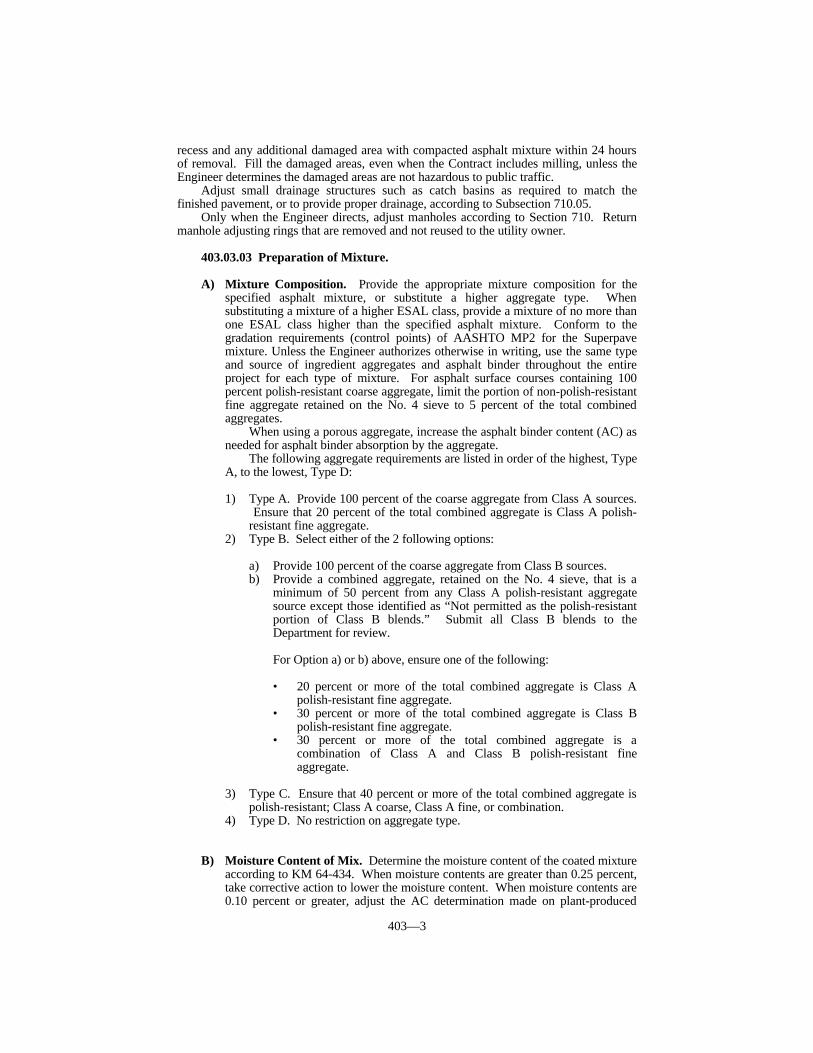
403—3
recess and any additional damaged area with compacted asphalt mixture within 24 hoursof removal. Fill the damaged areas, even when the Contract includes milling, unless theEngineer determines the damaged areas are not hazardous to public traffic.
Adjust small drainage structures such as catch basins as required to match thefinished pavement, or to provide proper drainage, according to Subsection 710.05.
Only when the Engineer directs, adjust manholes according to Section 710. Returnmanhole adjusting rings that are removed and not reused to the utility owner.
403.03.03 Preparation of Mixture.
A) Mixture Composition. Provide the appropriate mixture composition for thespecified asphalt mixture, or substitute a higher aggregate type. Whensubstituting a mixture of a higher ESAL class, provide a mixture of no more thanone ESAL class higher than the specified asphalt mixture. Conform to thegradation requirements (control points) of AASHTO MP2 for the Superpavemixture. Unless the Engineer authorizes otherwise in writing, use the same typeand source of ingredient aggregates and asphalt binder throughout the entireproject for each type of mixture. For asphalt surface courses containing 100percent polish-resistant coarse aggregate, limit the portion of non-polish-resistantfine aggregate retained on the No. 4 sieve to 5 percent of the total combinedaggregates.
When using a porous aggregate, increase the asphalt binder content (AC) asneeded for asphalt binder absorption by the aggregate.
The following aggregate requirements are listed in order of the highest, TypeA, to the lowest, Type D: 1) Type A. Provide 100 percent of the coarse aggregate from Class A sources.
Ensure that 20 percent of the total combined aggregate is Class A polish-resistant fine aggregate.
2) Type B. Select either of the 2 following options:
a) Provide 100 percent of the coarse aggregate from Class B sources.b) Provide a combined aggregate, retained on the No. 4 sieve, that is a
minimum of 50 percent from any Class A polish-resistant aggregatesource except those identified as “Not permitted as the polish-resistantportion of Class B blends.” Submit all Class B blends to theDepartment for review.
For Option a) or b) above, ensure one of the following:
• 20 percent or more of the total combined aggregate is Class Apolish-resistant fine aggregate.
• 30 percent or more of the total combined aggregate is Class Bpolish-resistant fine aggregate.
• 30 percent or more of the total combined aggregate is acombination of Class A and Class B polish-resistant fineaggregate.
3) Type C. Ensure that 40 percent or more of the total combined aggregate ispolish-resistant; Class A coarse, Class A fine, or combination.
4) Type D. No restriction on aggregate type.
B) Moisture Content of Mix. Determine the moisture content of the coated mixtureaccording to KM 64-434. When moisture contents are greater than 0.25 percent,take corrective action to lower the moisture content. When moisture contents are0.10 percent or greater, adjust the AC determination made on plant-produced
403—4
mixture to reflect the actual AC as KM 64-434 directs. The Engineer willdetermine the frequency of moisture content testing.
C) Mix Design Criteria. Conform to the gradation requirements (control points) ofAASHTO MP2 for the Superpave mixture type the Contract specifies.
1) Preliminary Mix Design. Submit a preliminary mix design, completed usinga Superpave gyratory compactor (SGC) conforming to AASHTO PP 35. Perform the volumetric mix design according to AASHTO PP28 andconforming to AASHTO MP2. The Department will require a dust-to-binder ration range of 0.8 to 1.6. Complete the volumetric mix design at theappropriate number of gyrations as given in AASHTO PP28 for the numberof ESAL’s. The Department will define the relationship between ESALclasses, as given in the bid items for Superpave mixtures, and ESAL rangesas follows:
Class ESAL’s (millions)1 < 0.32 0.3 to < 3.03 3.0 to < 30.04 > 30.0
2) Selection of Optimum AC. Normally, the Department will approve the ACat an air-void content of 4.0 percent. The Engineer may assign an ACcorresponding to other air-void levels as deemed appropriate. Ensure theoptimum AC is a minimum of 5.0 percent by weight of the total mixture forall 0.5-inch nominal surface mixtures and 5.3 percent by weight of the totalmixture for all 0.38-inch nominal surface mixtures.
3) Tensile Strength Ratio (TSR). Analyze the mixture for TSR according toASTM D 4867 with one freeze/thaw cycle, 150-mm specimens compactedwith a SGC, and a target degree of saturation of the conditioned specimensof 65 ± 5 percent.
403.03.04 Transporting Material. Securely fasten all covers in place on the truckbefore leaving the plant. During cool weather, or when an unexpected delay occurs, keepthe loads covered until just before unloading. Insulate truck beds, when necessary, tomaintain the specified temperature to the point of delivery. Do not use any truck thatcauses excessive segregation of mixture or that leaks.
403.03.05 Spreading and Finishing. Prevent segregation of the fine and coarseaggregates during all phases of construction. Spread the mixtures with a paver. Heat thescreed uniformly throughout its length. Do not allow flames to directly contact themixture. Adjust the paver speed to provide the best results for the mixture being used andto coordinate with the rate of delivery of the mixture to the paver to provide a uniformplacement rate without intermittent operation. Operate the screed or strike-off assemblywithout tearing, shoving, or gouging the mixture when laying the mixture. Operatevibrating screeds or other compacting features of the paver according to the manufacturer’srecommendations during the placement of the pavement.
Use automatic screed and slope controls. However, if the Engineer determines thatunder certain conditions better results may be obtained without using the controls, then theEngineer may waive using either the grade control or slope control requirements, or both.
Notify the plant to stop shipment whenever the automatic screed controls break downor malfunction. Obtain the Engineer’s approval to manually operate the equipment, oroperate it by other methods, to place the remainder of material already in transit, providedthe method of operation produces results otherwise conforming to this section.
Obtain vertical control for the outer edges of each mainline roadway from reference
403—5
lines or by using a ski arrangement. The Department will allow obtaining horizontalcontrol from the reference line. Automatically control the grade and slope for intermediatelines using reference lines, or a ski and a slope control device, or a dual ski arrangement.
Immediately after striking off and before rolling, visually inspect each course forirregularities, and correct if necessary. Keep hand raking of the mixtures to the absoluteminimum. Ensure that the finished surface has a uniform appearance, free fromsegregated areas. Immediately remove and replace, as directed, all portions of a pavementcourse that are defective in mixture composition, show excessive segregation, or do nototherwise comply with the Contract.
Correct irregularities in alignment of the outside edge or edges of longitudinal jointsby adding or removing material before compacting the edges.
Over uniform, narrow areas, such as widening or narrow, paved shoulders where theuse of pavers would be impractical, spread by a mechanical spreader. Ensure that thematerial is placed to the required lines, grades, and cross section without segregation of themixture.
Over areas where machine spreading is impractical due to irregularities orobstructions, spread the mixture by approved methods. Place the material to avoidsegregation and to reduce to a minimum the amount of patching required duringcompaction. Discard all coarse aggregate particles brought to the surface by raking.
Spread all surface courses with allowances made for compacting to finishapproximately 3/8 inch above forms, gutters, or similar construction.
The Department may allow shoulders and Asphalt Mixture for Pavement Wedge to bepaved monolithically with the mainline if it is in the best interest of the Department. Obtain the Engineer’s approval before doing so.
Do not place or compact asphalt mixture when the natural light is insufficient withoutproviding artificial lighting satisfactory to the Engineer. Unless the Contract specifiesnighttime paving, do not place binder, surface, or other asphalt mixture wearing courses atnight, without first obtaining the Engineer’s permission. The Engineer may requiredaytime paving if the Engineer deems the nighttime work unsatisfactory.
403.03.06 Thickness Tolerances. Place asphalt mixtures at the lift thicknessspecified in the Contract. The Engineer may allow the base lifts to be adjusted to improverideability provided the total base thickness remains the same.
A) Initial Treatment and Resurfacing Projects. Ensure that the total combinedthickness of each class of asphalt base conforms to the Contract. Control thethickness by the rate of application. Place the mixture at the Contract specifiedweight per square yard. Do not exceed the rate of application by more than 5percent.
B) New Construction. The Engineer will make thickness checks according to KM64-420, as soon as practical after completion of all, or a major portion, of theasphalt base. When desired, supply the personnel and equipment, and coreaccording to KM 64-420 under the Engineer’s supervision. The Engineer willmeasure the cores. Fill all core holes either with compacted asphalt mixture ornon-shrink grout. Complete all remedial overlay work before placing the finalcourse.
When constructing an overlay, match the grades of the adjacent work suchas storage lanes, approaches, entrances, etc., to the overlay section, whether theseadjacent areas are deficient in thickness or not.
Ensure the total combined thickness of all layers is within ± 1/2 inch of thecompacted plan thickness.
When there is an asphalt binder course, consider it as asphalt base for thepurpose of determining compliance with thickness tolerances.
When the top layer of a new pavement is OGFC or sand asphalt surface,consider all asphalt mixtures beneath that course as asphalt base for the purposeof determining compliance with thickness tolerances specified hereinafter.
When the Engineer determines the asphalt base is deficient in total thickness

403—6
by more than 1/2 inch from the compacted plan thickness, overlay the full widthpavement to bring the pavement to the required plan thickness. When placingadditional material is not feasible due to structures, drainage, or otherengineering reasons, the Engineer may waive the requirement for overlaying.
403.03.07 Joints. When curbs, gutters, pavement, and other structures adjoin thenew construction, coat all contact surfaces of the existing construction and joints ofpreviously placed new construction, both longitudinal and transverse, with tack.
When the pavement construction consists of 2 or more courses, offset the longitudinaljoint a minimum of 6 inches. Place the longitudinal joint in the final surface course alongthe dividing line between the lanes. Clean adjacent surfaces of all loose materials so thejoint shall receive full compaction from the rollers.
Place and spread all courses as continuously as possible, keeping the number of jointsto a minimum. When a transverse joint is necessary, complete the spreading of thematerial by the finishing machine, and adjust the course to a straight line, square with thepavement. Before work is resumed, cut back the joint on the previous run, exposing thefull depth of the course. Remove all excess material. Check the joint with a 10-footstraightedge at intervals of 2 feet or less immediately after initial rolling. Immediatelycorrect any irregularities not conforming to Subsection 403.03.11 either by additionalraking or adding hot material, or both. Discard all coarse aggregate particles brought tothe surface by raking. Roll joints to compress the material and to produce as tight a jointas possible.
Avoid cold longitudinal joints when practical by either placing the full width of thecourse in one pass, operating pavers in echelon, or moving pavers back each day afterplacing sufficient tonnage in each traffic lane so the course placed will be the full width ofthe pavement at the end of each day. Obtain the Engineer’s approval for the method ofpaving.
403.03.08 Rumble Strips.
A) Interstates and Parkways. Construct sawed rumble strips on all mainline andramp shoulders to the dimensions shown below.
B) Other Roads. When using a surface mixture instead of Asphalt Mixture forPavement Wedge, or when the Engineer deems it appropriate to pave the drivinglanes and the adjacent shoulder monolithically, provide rolled rumble strips. Construct strips on all mainline shoulders to the dimensions shown below. When furnishing Asphalt Mixture for Pavement Wedge, binder, or a basemixture for shoulders, the Department will not require rumble strips.
Time the rolling operation so indentations are at the specified size and depthwithout causing unacceptable displacement of the asphalt mat. Correctunacceptable rolled-in rumble strips by sawing.
On shoulders less than 3 feet, shorten the length and distance of the strips asthe Engineer directs.
Provided the shoulder is thick enough, the Department may allow sawedrumble strips in place of rolled rumble strips. Obtain the Engineer’s permissionbefore making the substitution.
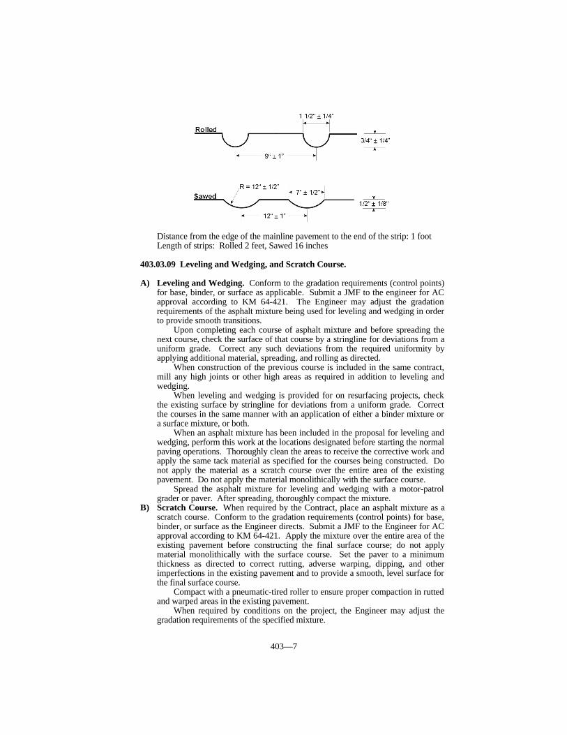
403—7
Distance from the edge of the mainline pavement to the end of the strip: 1 footLength of strips: Rolled 2 feet, Sawed 16 inches
403.03.09 Leveling and Wedging, and Scratch Course.
A) Leveling and Wedging. Conform to the gradation requirements (control points)for base, binder, or surface as applicable. Submit a JMF to the engineer for ACapproval according to KM 64-421. The Engineer may adjust the gradationrequirements of the asphalt mixture being used for leveling and wedging in orderto provide smooth transitions.
Upon completing each course of asphalt mixture and before spreading thenext course, check the surface of that course by a stringline for deviations from auniform grade. Correct any such deviations from the required uniformity byapplying additional material, spreading, and rolling as directed.
When construction of the previous course is included in the same contract,mill any high joints or other high areas as required in addition to leveling andwedging.
When leveling and wedging is provided for on resurfacing projects, checkthe existing surface by stringline for deviations from a uniform grade. Correctthe courses in the same manner with an application of either a binder mixture ora surface mixture, or both.
When an asphalt mixture has been included in the proposal for leveling andwedging, perform this work at the locations designated before starting the normalpaving operations. Thoroughly clean the areas to receive the corrective work andapply the same tack material as specified for the courses being constructed. Donot apply the material as a scratch course over the entire area of the existingpavement. Do not apply the material monolithically with the surface course.
Spread the asphalt mixture for leveling and wedging with a motor-patrolgrader or paver. After spreading, thoroughly compact the mixture.
B) Scratch Course. When required by the Contract, place an asphalt mixture as ascratch course. Conform to the gradation requirements (control points) for base,binder, or surface as the Engineer directs. Submit a JMF to the Engineer for ACapproval according to KM 64-421. Apply the mixture over the entire area of theexisting pavement before constructing the final surface course; do not applymaterial monolithically with the surface course. Set the paver to a minimumthickness as directed to correct rutting, adverse warping, dipping, and otherimperfections in the existing pavement and to provide a smooth, level surface forthe final surface course.
Compact with a pneumatic-tired roller to ensure proper compaction in ruttedand warped areas in the existing pavement.
When required by conditions on the project, the Engineer may adjust thegradation requirements of the specified mixture.
403—8
403.03.10 Compaction. Compact asphalt mixtures by Option A or B, as specified inthe Contract. When the compaction option is not specified, compact by Option B.
Operate the rollers to eliminate all roller marks and obtain the specified compaction.Operate vibratory rollers of a design, weight, and frequency that produces the specifiedcompaction without damaging the mat.
During the initial rolling of each course, visually inspect its surface for anyirregularities that may develop. Remove and replace areas in which the material is not incompliance with the specified mixture requirements.
Move the rollers at a slow but uniform speed with the drive roll or wheels nearest thepaver. Immediately correct any displacement due to reversing the direction of a roller, orfrom other causes, using rakes and adding fresh mixture when required. While rolling, donot displace the line and grade of the edges of the asphalt mixture.
To prevent adhesion of the material to the roller wheels, keep the wheels moistenedwith water, but do not use excess water. Do not use kerosene, oil, or other harmful liquids. The Department will allow a small quantity of detergent to be mixed with the water.
Compact areas adjacent to manholes, curbs, narrow widening, and other small areasinaccessible to a roller, by mechanical tampers.
A) Compaction Under Option A. Develop the rolling pattern during the firstsublot.
B) Compaction Under Option B. Provide initial or breakdown rolling consistingof one complete coverage by a 3-wheel roller or tandem roller weighing at least10 tons and having a compressive capability on the rear wheels of at least 325pounds per linear inch of wheel width. Ensure that 3-axle, steel-wheeled rollersweigh at least 12 tons. Ensure that 2-axle, steel-wheeled, tandem rollers weighat least 10 tons. For initial or breakdown rolling, provide rollers that areequipped with wheels having a diameter of 40 inches or more. Perform therolling immediately after spreading and finishing the mixture.
Provide intermediate rolling consisting of at least 3 complete coverages witha tandem roller weighing at least 10 tons. Start intermediate rolling aftercompleting the breakdown rolling as closely as possible without causing unduedisplacement, cracking, or shoving of the material.
For intermediate rolling of 1 1/2-inch and 1-inch nominal size mixes, use apneumatic-tired roller. Use pneumatic-tired rollers that weigh at least 12 tonsand have 7 to 9 tires capable of inflation pressures up to 125 psi. Maintain aninflation pressure in all tires within ± 5 psi of the manufacturer’s recommendedpressure. Arrange the tires so that the gap between the tires of the front axle iscovered by the tires of the rear axle. Mount wheels to provide equal contactpressure under each wheel. Use a tire tread that is satisfactory to the Engineer. Maintain tire size and inflation pressure such that the contact pressure is at least80 psi.
Perform final rolling of the uppermost layer or surface course with a tandemroller. Operate the roller, at all times, parallel to the centerline. When theEngineer allows, use the pneumatic-tired roller for rolling on base courses.
Begin rolling at the sides and progress to the center on crowned surfaces.Begin rolling at the low side and progress to the high side on superelevatedsections. Operate the rollers parallel to the centerline and lap successive trips ofeach roller uniformly to the previous trip. During breakdown rolling, theEngineer may allow the course to be rolled without the required lap of the wheelson successive trips. End alternate trips of the rollers on transverse lines at least 3feet apart. Regulate starting and stopping of the rollers to avoid distorting thesurface. Do not allow the rollers at any time to stand on the material beingplaced immediately behind the paver. When rolling is temporarily suspended,stop the rollers as far behind the paver as practical.
When using a 3-wheel roller, roll as directed. Do not use a 3-wheel roller toroll over a crown or over a warped section when the center axle is in the lockedposition.

403—9
The Engineer may allow a different rolling pattern. Submit the alternaterolling pattern for approval. Provide any demonstration or testing the Engineerrequires. Obtain written approval from the Engineer before continuing with thealternate pattern.
403.03.11 Surface Tolerances. Check the surface of each course with templates,straightedges, or stringlines. Check the surfaces of the finished courses longitudinallywith a 10-foot straightedge placed parallel to the centerline over the width of the surface.
Ensure the following:
1) The finished surfaces of the base and binder courses do not deviate more than 1/4inch from the 10-foot straightedge.
2) The finished surface of the final surface course does not deviate more than 1/8inch from the 10-foot straightedge.
3) The cross slope of all courses does not deviate more than 1/4 inch in 5 feet fromthe required cross slope.
4) The asphalt surface conforms to all requirements for a final surface course whenthe top portion of a new pavement consists of a wearing course underlain byasphalt surface.
Correct all irregularities exceeding the allowable tolerances. Correct surface courseirregularities by removing and replacing the entire lift thickness or by overlaying. Do notremove the irregular areas of the surface course by surface grinders.
On resurfacing projects, when no provisions are made for constructing leveling andwedging courses, scratch courses, or milling, the Engineer will waive the specifiedrequirements for surface tolerances.
403.03.12 Transverse Joints. When specified in the Contract, cut transverse jointsin overlays of JPC pavement, base, and shoulders. Seal with self-leveling silicone rubbersealant.
403.03.13 Pavement Marking. Apply and maintain pavement marking as specifiedin Section 112.
403.04 MEASUREMENT.
403.04.01 Removing Type V Pavement Markers. The Department will measurethe quantity by each individual unit. The Department will determine the quantity bydividing the length of each run of markers by the markers’ average spacing, plus one.
The Department will not measure other marker types for removal, disposal, or fillingof their grooves for payment. The Department will consider all of this work incidental tothe surfacing items in the Contract.
403.04.02 Adjust Manhole. The Department will measure the quantity by eachindividual unit.
403.04.03 Asphalt Mixtures. The Department will measure the quantity accordingto Subsection 402. The Department will not measure rumble strips for payment and willconsider them incidental to this bid item.
403.04.04 Leveling and Wedging. For resurfacing projects, when leveling andwedging is listed as a bid item, the Department will measure the quantity in tonsaccording to Subsection 402.04. For reconstruction and new construction, the Departmentwill measure the quantity of leveling and wedging placed on the first base course in tons asbase material. The Department will not measure leveling and wedging used to correctirregularities in subsequent courses for payment and will consider it incidental to placingthe course.

403—10
403.04.05 Asphalt Scratch Course. The Department will measure the quantityaccording to Section 402.04.
403.04.06 Protective and Restorative Work. The Department will not measure forpayment any extra materials, methods, or construction techniques, determined by theEngineer not to be a part of the specified construction, used to protect, maintain, or repairany portion of the uncompleted work during the winter months.
403.05 PAYMENT. The Department will make payment for the completed andaccepted quantities under the following:
403.05.01 Adjust Manhole. In the event the Engineer directs the Contractor toadjust existing manholes and the Contract does not include a bid item for this work, theDepartment will make payment at an agreed unit price of $250.00 for each manholeacceptably adjusted by using the adjusting ring method, or an agreed unit price of $350.00for each manhole acceptably adjusted by removing or adding masonry.
403.05.02 Asphalt Mixtures. The Department will make payment for the completedand accepted quantities according to Section 402.
403.05.03 Leveling and Wedging. The Department will make payment for thecompleted and accepted quantities according to the Lot Pay Adjustment Schedule forSpecialty Mixtures in Section 402.
403.05.04 Asphalt Scratch Course. The Department will make payment for thecompleted and accepted quantities according to the Lot Pay Adjustment Schedule forSpecialty Mixtures in Section 402.
Code Pay Item Pay Unit6600 Remove Pavement Marker Type V Each1791 Adjust Manhole Frame to Grade Each
The Department will consider payment as full compensation for all work requiredunder this section.
404—1
SECTION 404 OPEN-GRADED FRICTION COURSE (OGFC)
404.01 DESCRIPTION. Construct one course of hot-mixed, hot-placed, OGFCapproximately 3/4-inch thick on a foundation provided by either new or existingpavements.
404.02 MATERIALS AND EQUIPMENT.
404.02.01 Aggregates. Conform to Subsection 403.02 and the following:
A) Fine Aggregate. Limit sands from sources not included in the Polish-ResistantAggregate Sources section of the Department’s List of Approved Materials to 20percent of the total aggregate in the mixture.
B) Coarse Aggregate. Provide 100 percent Class A polish-resistant aggregate.
404.02.02 Asphalt Binder. Provide the PG binder specified in the Contractconforming to Section 806.
404.02.03 Anti-stripping Additive. Select from the Department’s List of ApprovedMaterials.
404.02.04 Tack. Conform to Section 806.
404.03 CONSTRUCTION. Conform to Section 403, except as provided in this sectionand in the Contract. The OGFC is intended to provide a coarse-textured, well-draining,skid-resistant wearing surface. Construct this course at a higher elevation than adjacentgutters to provide proper lateral drainage of water through the course.
For multiple lanes in the same direction, place the material continuously in one laneeach day. Protect it from traffic until it has cured overnight.
When placing OGFC on two-lane, two-way pavements, operate the paver accordingto Subsection 403.03.05.
404.03.01 Weather Limitations. In addition to the weather limitations specified inSubsection 403.03.01, do not place OGFC between September 15 and May 1, withoutobtaining the Engineer’s written permission.
404.03.02 Leveling and Wedging. Perform the necessary leveling, wedging, andpatching to repair an existing pavement before beginning construction of this surfacecourse.
404.03.03 Tack Coat. Apply according to Section 406, except as follows. Whenfurnishing emulsions for the tack coat, do not dilute the emulsions. Apply undiluted SS-1,SS-1h, RS-1, or RS-2 at an approximate rate of 0.8 pounds (0.1 gallons) per square yard.
404.03.04 Preparation of Mixtures. Submit the JMF for OGFC for approvalaccording to Subsection 402.03. Conform to the gradation requirements specified. TheDepartment will perform a mix design according to KM 64-424.
Test the approved JMF of the mixture according to KM 64-433 or KM 64-620, andensure that it conforms to the requirements shown in the table below.
During the operation of the plant, conform to the following tolerances from theapproved JMF, and also maintain the master gradation ranges below at all times.
404—2
Obtain the Engineer’s approval for the percent by weight of asphalt binder in themixture. Do not deviate from the established AC by more than 0.4 percent. Test themixture according to KM 64-405, KM 64-436, KM 64-437, KM 64-438 or AASHTO T308.
Use the anti-stripping additive at the rate of 0.5 percent by weight of asphalt binder.Maintain temperatures of the ingredient materials and the mixture within the
following ranges:
Spread the OGFC at an approximate rate of 65 pounds per square yard to provide anapproximate thickness of 3/4 inch.
Roll with a steel-wheel, tandem roller weighing between 5 and 8 tons. Begin rollingimmediately after placing the course. Limit rolling to the minimum necessary forconsolidating the mixture and bonding it to the underlying surface. Avoid excessiverolling and breakage of the aggregate.
404.04 MEASUREMENT. The Department will measure the quantity in tonsaccording to Subsection 402.04. The Department will not measure asphalt tack coat andanti-strip additives for payment and will consider them incidental to this item of work.
404.05 PAYMENT. The Department will calculate payment by the Lot PayAdjustment Schedule for Specialty Mixtures in Section 402.
The Department will apply the schedule’s tolerances to the average of the absolutevalues of deviations from the JMF.
When the deviation is on the high side of the JMF, the Engineer will evaluate eachoccurrence and determine if it is detrimental to the pavement performance and whether themixture is acceptable at no deduction, at some deduction, or must be removed andreplaced.
When a pay factor less than 1.00 is determined for gradation on more than one sieve,the Department will use the lowest single pay factor determined.
When a pay factor less than 1.00 is determined for both AC and gradation on one or
SIEVE MASTER GRADATION RANGE JMFSIZE (Percent Passing by Weight) TOLERANCES
1/2 inch 1003/8 inch 90-100
No. 4 25-50 ± 6%No. 8 5-15 ± 4%
No. 16 -No. 200 2.0-5.0
MIXING AND LAYING TEMPERATURES (°F)
Material Minimum MaximumAggregates 240 330Asphalt Binders PG 64-22 230 330
PG 70-22 285 350PG 76-22 285 350
Asphalt Mixtures at Plant PG 64-22 230 265(Measured in Truck) PG 70-22 265 310
PG 76-22 275 320Asphalt Mixtures at Project PG 64-22 175 265(Measured in Truck PG 70-22 230 310 When Discharging) PG 76-22 260 320
404—3
more sieves, the Engineer will evaluate and determine if the deficiencies will have acumulative negative influence on the mixture. If so, the Engineer will apply both thereduced pay factor for the AC and the largest deduction for the gradation failures. If not,the Engineer will apply the larger single deduction.
The Department will make payment for the completed and accepted quantities underthe following:
Code Pay Item Pay Unit0266-0268 Asphalt Surface, Open-Graded, Grade Ton
The Department will consider payment as full compensation for all work requiredunder this section.
405—1
SECTION 405 ASPHALT SEAL COAT
405.01 DESCRIPTION. Construct an asphalt seal coat consisting of one or moreapplications each of asphalt material and cover aggregate.
405.02 MATERIALS AND EQUIPMENT.
405.02.01 Asphalt Material. Furnish the type and grade specified in the Contractconforming to Section 806.
405.02.02 Aggregate. Conform to Section 804 or 805, as applicable.
405.02.03 Equipment. Provide, and keep on the project at all times, an accuratethermometer, hand brooms, and other small tools and equipment essential for completionof the work.
Provide equipment for heating the asphalt material and pressure distributorsconforming to Subsection 406.02.04.
Provide a mechanical broom or sweeper for cleaning the existing surface and forsweeping the completed seal coat.
Provide an aggregate spreader of an approved type equipped with a mechanical feed.Ensure that the spreader is capable of depositing aggregate from the transporting vehicledirectly onto the fresh asphalt material at the rate specified, in smooth, uniform layers,independent of the forward speed. Ensure that the spreader is capable of being filled andmoved without discharging aggregate.
Provide a pneumatic-tired roller for roadway surfaces. On slopes, the Departmentwill allow a steel-wheel roller.
405.03 CONSTRUCTION.
405.03.01 Weather Limitations. Do not construct any seal coat when the ambienttemperature is below 45 °F, nor when the ambient temperature within the preceding 24hours has been 35 °F or lower, except with the Engineer’s written permission.
405.03.02 Preparation of Surface. Sweep the road with a mechanical sweeper andwith wire hand brooms, when necessary. Clean the edges of the surface so that the fullwidth of the roadway to be treated is uniformly clean. Where any mud or earth exists,remove it in advance of the application of the asphalt material, and allow the surface tothoroughly dry.
If cracks cannot be adequately filled by the seal coat, fill them with asphalt materialand apply cover aggregate before applying the seal coat.
405.03.03 Heating and Applying Asphalt Material. Heat and maintain the asphaltmaterial within the following temperature ranges during application:
RS-1 70 - 140 °FRS-2, CRS-2, HFRS-2 125 - 175 °F
Apply asphalt material by means of a pressure distributor in a uniform, continuousspread over the section to be treated in the quantity per square yard specified in theContract or as the Engineer directs.
Keep the nozzles of the spray bar clean at all times. Immediately make uniform anystreaked areas by use of a hand hose equipped with a nozzle.
Treat areas over which it is impractical to operate a distributor by means of a handhose equipped with a nozzle or by means of a pouring pot.
Do not apply the asphalt material farther in advance of the spreading of the aggregatethan can be covered directly by the aggregate immediately available at the site of work.

405—2
When the seal coat treatment is constructed in half-widths, provide complete coverageby overlapping the 2 applications approximately 4 inches along the centerline.
Prevent spotting or discoloring curbs, headwalls, and other structures. When suchdiscolorations occur, remove them at no expense to the Department.
Make joints utilizing an approved method.
405.03.04 Application of Cover Material. Provide the gradation specified in theContract. Ensure that the aggregate for cover material is surface-dry when applied, unlessdamp aggregate is allowed or required due to the type of asphalt material being used.Spread the aggregate immediately following the application of the asphalt material. Spreadthe aggregate before the asphalt material breaks. Ensure that the spreading equipmentdoes not contact the asphalt material before it is covered with aggregate. Apply the covermaterial at the rate designated in the Contract, with precautions taken not to exceed thedesignated rate by more than 5 percent. Use hand brooms to correct any irregularities.
When applied on the roadway lanes and shoulders, roll the entire surface width withpneumatic-tired rollers immediately following the spreading of the aggregate. Do not usesteel-wheel rollers. Operate the rollers parallel to the centerline, and cover the entiresurface with at least 3 passes of the rollers, or more when the Engineer directs.
When applied on the roadway lanes and shoulders, after rolling, mechanically sweepthe completed seal coat to remove all excess cover aggregate after the asphalt material hascured sufficiently to allow sweeping without dislodging the imbedded aggregate, whendeemed necessary. If an asphalt surface course is to be applied over the seal coat, do notallow traffic on the seal coat before applying the surface course unless required by thetraffic control plan or the Engineer.
405.04 MEASUREMENT. When an authorized adjustment is made, the Departmentwill measure quantities up to 5 percent in excess of the designated application rate forpayment. The Department will not measure quantities exceeding the designatedapplication rate by more than 5 percent for payment.
405.04.01 Asphalt Material for Asphalt Seal Coat. The Department will measurethe quantity in tons according to Section 109.
405.04.02 Asphalt Seal Aggregate. The Department will measure the quantity intons according to Section 109.
405.05 PAYMENT. The Department will make payment for the completed andaccepted quantities under the following:
Code Pay Item Pay Unit---- Asphalt Material for Asphalt Seal Coat Ton0100 Asphalt Seal Aggregate Ton
The Department will consider payment as full compensation for all work requiredunder this section.

406—1
SECTION 406 ASPHALT CURING SEAL AND ASPHALTPRIME AND TACK COATS
406.01 DESCRIPTION. Prepare existing bases or surfaces, and apply liquid asphaltmaterial before placing covering courses of asphalt mixtures or treatments.
406.02 MATERIALS AND EQUIPMENT.
406.02.01 Tack Coat. Furnish any of the following asphalt materials conforming toSection 806: SS-1, SS-1h, or RS-1.
406.02.02 Prime Coat. Furnish Primer-L conforming to Section 806 unless theContract allows another material.
406.02.03 Curing Seal. Furnish any of the following asphalt materials conformingto Section 806: RS-1, RS-2, SS-1, SS-1h, or Primer L.
406.02.04 Water. Conform to Section 803.
406.02.05 Equipment. Provide hand brooms and other small tools and equipmentessential to completing the work in addition to a mechanical broom or sweeper, asphaltheating equipment, and a pressure distributor. Provide a mechanical broom or sweeperthat is adjustable to make uniform contact with the surface and that thoroughly cleanswithout cutting into the surface being swept.
Provide equipment for heating the asphalt material in tanks, railroad cars, trucks, anddistributors that is capable of heating the material to the required temperature withoutintroducing moisture, localized overheating, or otherwise changing the characteristics ofthe material.
Mount the pressure distributor on a self-propelled, motor vehicle equipped withpneumatic tires, and ensure that it has sufficient power to maintain a constant and uniformspeed under all operating conditions. Use a distributor designed to apply the materialuniformly at the rate required for the type of construction. Use a distributor conforming tothe following requirements:
A) Tank. Use a tank with a capacity of at least 600 gallons and equipped with aremovable manhole cover, an overflow pipe, and a dial gage for indicating thecontents (mounted so as to be plainly visible to the operator). Carry an accuratemeasuring stick on the distributor at all times.
B) Heating System. Ensure that the heating system evenly heats and maintains theasphalt material within the required temperature range at all times. Provide atemperature measuring device that will quickly and accurately determine thetemperature of the material.
C) Distributing System. Ensure that the pressure distributing system contains aseparate power and pump unit of sufficient capacity to distribute the requiredquantity of asphalt material at a constant flow and uniform pressure. Mount adial pressure gage plainly visible to the operator.
D) Spray Bar and Nozzles. Use a full-circulating spray bar that adjusts in length toconform to the width of the application being made without overlapping. Use aspray bar that swings laterally over a distance of 9 inches or more. Provide apositive and immediate cut-off and means to prevent material from dripping ontothe road surface when the flow is shut off. Use individual nozzles that maintainan equal flow from all nozzles at the same time. To prevent clogging of thenozzles, provide screens for the circulating system, and keep the screens clean.Also, provide a hand spray bar and nozzle having an adequate length of flexiblesteel hose with packed couplings.
E) Tachometer or Synchronizer. Have a tachometer visible to the truck operator
406—2
to enable him to maintain the constant speed necessary for the application of thespecified quantity of material. Furnish suitable charts showing the truck speedsnecessary for the correct application.
When using a synchronizer, the tachometer may be omitted. Use asynchronizer that delivers a specified quantity of asphalt material onto the roadsurface independent of the truck speed.
406.03 CONSTRUCTION. For the asphalt prime coat, apply liquid asphalt material togranular-type bases.
For the asphalt tack coat, apply liquid asphalt material to the surface of concrete orbrick pavements and bases, to existing asphalt surfaces and, when necessary, to newlyconstructed asphalt courses.
406.03.01 Weather Limitations. Conform to the temperature limitations specifiedfor the asphalt mixture to be placed. Do not apply prime and tack coats to wet surfaces.
406.03.02 Preparation of Surface. Obtain the Engineer’s approval of the preparedsurface before applying the prime or tack coat.
A) Asphalt Prime Coat. Grade and shape the existing traffic bound base to therequired grade and cross section before applying any asphalt material. Wet androll salvable floater material into the existing traffic bound base.
B) Asphalt Tack Coat. Use mechanical sweepers to clean the application surfacesof all dirt and other foreign matter. Use wire hand brooms when necessary.Extend sweeping beyond the edges of the surface to ensure a thorough cleaningof the full width to be treated.
C) Asphalt Curing Seal. Ensure the roadbed surface is dense, free from looseextraneous material, and contains sufficient moisture to prevent penetrationof the asphalt material.
406.03.03 Application. Provide necessary barricades, warning signs, and flaggers toprevent traffic from traveling over a freshly applied prime or tack coat. Also, provide forpublic convenience and safety as specified in Sections 104 and 107.
Prevent spotting or discoloring curbs, headwalls, and other structures. Whendiscolorations occur, remove them at no expense to the Department.
Protect the exposed, treated surfaces from damage. Repair all damaged areas.Maintain the material within the following temperature ranges during application:
Primer-L 60-120 °FSS-1, SS-1h 70-160 °FRS-1, RS-2 70-140 °F
A) Asphalt Prime Coat. Apply prime coats at the rate specified in the Contract, oras directed when conditions justify variations in the rates of application.
Apply the number of applications of the prime coat as directed. Apply thematerial under pressure. Do not use hand-pouring except for special conditions,and then only with the Engineer’s approval.
Allow the prime coat to cure before placing the asphalt mixture courseunless the Engineer approves otherwise.
B) Asphalt Tack Coat. Apply the tack coat with a spray bar that can be raised to asufficient height so as to uniformly and completely coat the entire surface. Whena uniform application, at the rate required, cannot be obtained from a spray bar,then apply the tack coat by fogging with a hand spray attachment. The Engineerwill only accept complete and uniform coverage. Unless otherwise specified inthe requirements for the asphalt mixture being placed, apply tack at a rate toachieve an undiluted residue of 0.4 pounds (0.05 gallons) per square yard.
When furnishing RS-1 for tack, apply it undiluted.

406—3
When furnishing SS-1 or SS-1h for tack, the Department will allow dilutedor undiluted application provided uniform and complete coverage is achieved. When applying tack in a diluted form, apply it a sufficient time in advance toensure that all water has evaporated before placing the asphalt mixture.
On newly constructed base and binder courses, adjust the application rate asthe Engineer directs.
When placing asphalt material adjacent to curbs, existing pavements, orother structures, first coat the contact surface of the existing structure with tackmaterial.
If the initial application of any tack material is not uniform, apply additionalmaterial as directed at no additional expense to the Department.
Remove asphalt material applied in excess of the requirements, or cover itwith a blotter course of dry sand or stone chips as the Engineer directs.
On projects over which public traffic is being maintained, apply the tackcoat over one-half of the pavement width, not to exceed one-half day’s work, inadvance of the construction of the asphalt cover course. Do not end the tack coatapplication at a location hazardous to traffic. Do not apply tack coat to a lanethat requires overnight closure, unless the Engineer approves it in writing. Schedule the work so that at the end of the day’s production all tack is coveredwith the asphalt mat or a sand blotter course. At road intersections or othertraffic crossings, the Engineer may require the application of a sand blottercourse over the tack coat.
When Sand for Blotter is included in the Contract as a bid item, cover thetack coat with surface-dry, natural sand in a minimum quantity sufficient toprevent the tack coat from being picked up by traffic. Apply the sand uniformlyat the rate the Engineer directs but not exceeding 5 pounds per square yard. Thenormal rate is 2 to 3 pounds per square yard.
C) Asphalt Curing Seal. Uniformly apply the curing seal at the rate ofapproximately 2.0 pounds per square yard. The Engineer will determine theactual rate and application temperature of asphalt material. Apply the curing sealin sufficient quantity to provide a continuous membrane over the roadbed. Toavoid excessive runoff, apply the seal in 2 or more applications when directed orallowed, making each application as soon as possible after the previousapplication. If any damage occurs, immediately reseal the damaged area.
If the asphalt material is sticky, apply a sand blotter material at a rate ofapproximately 5 pounds per square yard, when the Engineer directs, to avoiddamage to the seal or to avoid tracking material onto other facilities.
406.04 MEASUREMENT. The Department will not measure for payment the removalof discolorations, maintenance, and repair of the applied coating, or removal of excessmaterial.
406.04.01 Cutback Asphalt Emulsion Primer-L. The Department will measurethe quantity according to Section 109. The Department will not measure water used toprepare dry surfaces for payment.
406.04.02 Asphalt Material for Tack. The Department will not measure tack forpayment and will consider it incidental to the asphalt courses.
406.04.03 Asphalt Curing Seal. The Department will measure the quantityaccording to Section 109. The Department will not measure water used to prepare drysurfaces for payment.
406.04.04 Sand for Blotter. When listed as a bid item, the Department willmeasure the quantity in tons according to Section 109. The Department will not measuresand for payment when used to treat excessive asphalt material application.

406—4
406.05 PAYMENT. The Department will make payment for the completed andaccepted quantities under the following:
Code Pay Item Pay Unit0296 Primer-L Ton0358 Asphalt Curing Seal Ton2702 Sand for Blotter Ton
The Department will consider payment as full compensation for all work requiredunder this section.

407—1
SECTION 407 ASPHALT MIXTURE FOR PAVEMENTWEDGE
407.01 DESCRIPTION. Construct a pavement wedge composed of a hot-mixed, hot-placed, asphalt mixture. Prepare the area to be covered by the mixture when necessary.
407.02 MATERIALS AND EQUIPMENT.
407.02.01 Asphalt Binder. Furnish either PG 58-22 or 64-22 conforming to Section806.
407.02.02 Aggregate. Conform to Sections 804 and 805. Use a gradation withinthe requirements in the following table:
Sieve Size Percent Passing1 1/2 inch 1003/4 inch 70-1003/8 inch 45-80
No. 4 30-60No. 8 20-45No. 16 15-35No. 50 5-20No. 100 3-10
Test gradation according to KM 64-433 or KM 64-620.Use an asphalt binder content (AC) between 4.5 and 6.0 percent by weight of the
mixture. When using a porous aggregate, increase the AC as needed to compensate forasphalt absorption by the aggregate. Submit a JMF to the Engineer for AC for approvalaccording to KM 64-421. Maintain the approved AC within ± 0.5 percentage points asdetermined according to KM 64-405, KM 64-436, KM 64-437, KM 64-438, or AASHTOT 308.
407.03 CONSTRUCTION. Conform to Section 403 except as specified in this sectionand in the Contract.
Construct the wedge to the depth, width, and slope the Contract specifies whereexisting conditions permit. Remove the sod or perform trench excavation only whennecessary to obtain the specified depth and width. Do not remove solid rock.
Compact the mixture with a roller weighing at least one ton.
407.04 MEASUREMENT. The Department will measure the quantity according toSubsection 402.04.
The Department will not measure trench excavation or sod removal performed asspecified in this section for payment and will consider them incidental to this item of work.
407.05 PAYMENT. The Department will make payment for the completed andaccepted quantities according to the Lot Pay Adjustment Schedule for Specialty Mixturesin Section 402 under the following:
Code Pay Item Pay Unit0263 Asphalt Mixture for Pavement Wedge Ton
The Department will consider payment as full compensation for all work requiredunder this section.
408—1
SECTION 408 ASPHALT PAVEMENT MILLING ANDTEXTURING
408.01 DESCRIPTION. Remove existing pavement by milling and texturing.
408.02 MATERIALS AND EQUIPMENT. Provide a power-operated, self-propelledmilling machine capable of:
1) removing asphalt pavement to the required depth, profile, cross slope, and surfacetexture;
2) accurately establishing profile grades by referencing from either the existing pavementor from an independent grade control;
3) controlling cross slope;4) applying sufficient down-pressure to plane the milled surface; and5) effectively removing cuttings from the pavement and preventing dust from escaping
into the air.
Provide supplemental equipment as necessary to remove material adjacent to curbs,railroad crossings, and other areas that cannot be removed by the milling machine.Additionally, provide a mechanical sweeper and, when the Engineer deems necessary, awater truck to control dust.
408.03 CONSTRUCTION. The depth of cut indicated in the Contract is approximateonly. The Engineer will specify the actual depth of cut.
When the Contract requires a bottom-of-rut cut, remove only the amount of materialnecessary to acceptably texture the bottom of the rut. Where there are no ruts, remove onlythe amount of material necessary to obtain an acceptable texture.
Remove the material in successive cuts of approximately 1 to 1 1/2 inches, measuredat the edge of the cutting drum. Complete each cut over the entire length and width of thearea. Do not begin the next cut until the Engineer examines the area and determines thatadditional cutting is necessary.
When maintaining public traffic is not necessary, the Department may allow deepercuts, provided the final cut does not exceed 1 1/2 inches and satisfactory results areobtained.
Provide an average depth of 0.20 inch between the high and low points on the milledpavement.
After milling and texturing, ensure that the finished surface conforms to the requiredgrade and cross section and provides a smooth riding surface free from gouges, ridges, oilfilm, and other imperfections of workmanship. Do not allow the elevation of thelongitudinal edges of adjacent cuts to differ more than 1/8 inch. Unless the Engineerallows, do not leave vertical longitudinal faces during non-working hours in areas exposedto public traffic. Limit the vertical longitudinal faces to 1 1/2 inches in height and taperthem in a manner the Engineer approves, to avoid creating a hazard for traffic.
When the Engineer deems necessary, apply water to control dust.Thoroughly sweep up all millings. Load and haul away all materials swept up.Repair pavement that is gouged, torn, or otherwise damaged during milling
operations, and repair damage done to any other property of any kind including utilityframes, grates, and covers.
408.03.01 Surface Tolerance. Ensure that the finished surface after the final cutdoes not deviate more than 1/8 inch from a 10-foot straightedge and that the cross slopedoes not deviate more than 3/8 inch in 10 feet. Correct all irregularities exceeding theselimits.
408.03.02 Approaches and Tapers. Mill approaches and tapers as required by, andto the satisfaction of, the Engineer. The Engineer will determine the length, width, and
408—2
depth of cut on approaches and tapers. Match the approaches and tapers to the finishedcut on the mainline and transition them to the existing surface to within 1/8 inch.
When the Engineer deems necessary, transition private entrances to provide a smoothapproach to the roadway.
408.03.03 Pavement Marking. Apply and maintain pavement markings accordingto Section 112.
408.03.04 Adjusting Small Drainage Structures. Adjust small drainage structures,such as catch basins, as required to match the finished pavement, or to provide properdrainage, according to Subsection 710.03.03. When existing catch basin grates are belowthe finished grade, the Department will require no adjustments.
Keep all small drainage structures, utility valves, etc. free of cuttings and other debrisduring the milling operation.
408.03.05 Adjusting Manholes. Only when the Engineer directs, adjust manholesaccording to Subsection 710.03.03. Return manhole adjusting rings that are removed andnot reused to the utility owner.
408.04 MEASUREMENT.
408.04.01 Asphalt Pavement Milling and Texturing. The Department willmeasure the quantity of material removed from the areas milled and textured in tons.
When the original Contract quantity is 2,000 tons or more, weigh the materialaccording to Section 109, except that the Department will accept commercial or portablescales, certified by the Kentucky Department of Agriculture, Division of Weights andMeasures, and approved by the Engineer.
When the original Contract quantity is less than 2,000 tons, arrange for 3 trucks ofeach capacity to be weighed to determine the average net weight per load. TheDepartment will calculate the total quantity using the average weight per load and the loadcount for each size of truck. The Engineer may require additional weighing if excessivevariation in loading is apparent. The Engineer may perform check-weighing.
The Department will not measure additional milling performed to correct deficienciesin the finished grade, cross section, or texture for material removed when the deficienciesare due to unsatisfactory workmanship.
The Department will not measure work to repair damage caused by the millingoperations.
The Department will not measure water used to control dust for payment and willconsider it incidental to this item of work.
408.04.02 Mobilization for Asphalt Pavement Milling and Texturing. TheDepartment will measure the quantity by the lump sum. The Department will measureMobilization for Asphalt Pavement Milling and Texturing for payment only once perContract and will consider any additional mobilization operations for milling and texturingincidental to this item of work.
The Department will not measure Mobilization for Asphalt Pavement Milling andTexturing for payment when milling is performed to correct deficiencies in the finishedgrade, cross section, or texture for material removed when the deficiencies are due tounsatisfactory workmanship.
For group contracts, the Department will measure the quantity for each project(subsection) that has a bid item for Mobilization for Asphalt Pavement Milling andTexturing.
408.04.03 Adjusting Small Drainage Structures. The Department will measurethe quantity according to Subsection 710.04.
408.04.04 Adjust Manhole. The Department will measure the quantity by each
408—3
individual unit.
408.05 PAYMENT. The Department will make payment for the completed andaccepted quantities under the following:
408.05.01 Asphalt Pavement Milling and Texturing. When Asphalt PavementMilling and Texturing is a major item, the Department will use the supplemental formulasestablished in Subsection 104.02.02 for determining adjusted unit prices when either anunderrun or an overrun of 25 percent occurs in the quantity of milling and texturingactually performed.
408.05.02 Adjust Manhole. In the event the Engineer directs the Contractor toadjust existing manholes and the Contract does not include a bid item for this work, theDepartment will make payment at an agreed unit price of $250.00 for each manholeacceptably adjusted by using the adjusting ring method, or an agreed unit price of $350.00for each manhole acceptably adjusted by removing or adding masonry.
Code Pay Item Pay Unit2677 Asphalt Pavement Milling and Texturing Ton2676 Mobilization for Milling and Texturing Lump Sum1709, 1719 Adjusting Small Drainage Structures, Type, Size See Subsection 710.05
1791, 17921791 Adjust Manhole Frame to Grade Each
The Department will consider payment as full compensation for all work requiredunder this section.
409—1
SECTION 409 ASPHALT MIXTURES USING RECLAIMEDMATERIALS
409.01 DESCRIPTION. Use reclaimed asphalt pavement (RAP) from Departmentprojects or other approved sources in hot asphalt mixtures, provided mixture requirementsare satisfied. For other sources to be approved, satisfactorily establish to the Engineer thatthe quality of the material is acceptable.
409.02 MATERIALS AND EQUIPMENT. Conform to the guidelines in Subsection409.03.02 for the required grade of asphalt binder which is based on the percentage ofRAP in the mixture.
409.03 CONSTRUCTION. Keep RAP of different gradation, asphalt binderpercentage, asphalt binder properties, and aggregate properties separate at all times,including when stockpiling and feeding. The Department may approve other methods andprocedures provided that all characteristics of the material remain uniform.
409.03.01 Restrictions. Do not use reclaimed materials in open-graded frictioncourses.
Before using RAP in asphalt mixtures requiring polish-resistant aggregate, providedocumentation to the Engineer’s satisfaction that the reclaimed material consists of a givenportion of polish-resistant aggregate.
When the mixture’s bid item specifies PG 76-22, limit RAP content to 20 percent orless.
409.03.02 Preparation of Mixture.
A) Mix Requirements. Conform to the Contract requirements for each mixtureproduced using RAP. If mixtures produced using RAP do not conform to therequirements for that mixture, complete the project using all virgin materials atno additional expense to the Department. Conform to the following table toselect the appropriate grade of virgin asphalt binder to blend with the RAP:
Appropriate Virgin Asphalt BinderMixture’sBid Item 0-20% RAP 21-30% RAP >30% RAPPG 76-22 PG 76-22 - -PG 70-22 PG 70-22 PG 64-22 *PG 64-22 PG 64-22 PG 64-22 *
*Select according to KM 64-427.
B) JMF. Develop the JMF, and submit it according to KM 64-421 to theDepartment for approval according to KM 64-427.
C) Mixing. Obtain the Engineer’s approval for the method of incorporating RAPinto the mixture. Thoroughly mix the new and reclaimed materials into auniform mass. Ensure that the final mixture conforms to all requirements of theContract. Ensure that the moisture content of the final mixture is not detrimentalto the handling, hauling, placing, or compacting of the mixture.
The Engineer may require a longer mixing time for the new aggregate andreclaimed material, before and after the addition of virgin asphalt binder, than isnormally specified.
409.04 MEASUREMENT. The Department will not measure RAP separately but willinclude it in the measured quantities of asphalt mixture produced.
409.05 PAYMENT. The Department will make payment for the completed andaccepted quantities under the appropriate pay item for the asphalt mixture being produced.

409—2
The Department will not make separate payment for incorporating RAP. TheDepartment will not increase or decrease the Contract unit prices for any asphalt mixtureon the project as a result of using, or not using, reclaimed material in the asphalt mixtures.
410—1
SECTION 410 ASPHALT PAVEMENT RIDE QUALITY
410.01 DESCRIPTION. This section covers the requirements for the ride quality ofcompleted asphalt pavements. Included are provisions for incentive payments foroutstanding work and deductions for acceptable, but lesser quality, work. Ride quality is ameasurement of surface tolerance in terms of a International Roughness Index (IRI). TheIRI is an index derived from controlled measurements of the longitudinal profile in thewheel tracks and correlated with panel ratings of ride quality. The Contract will specifywhen ride quality requirements apply.
410.02 MATERIALS AND EQUIPMENT. The Department will measure thelongitudinal profile of the surface with an ASTM E 950, Class 1 device.
410.03 CONSTRUCTION.
410.03.01 Lift Thickness. When the Engineer approves, the thickness of individuallifts of asphalt base may be adjusted to improve ride quality. Conform to Subsection403.03.06.
410.03.02 Corrective Work. Submit corrective work procedure plans to theEngineer for approval before performing the work. Provide a final surface comparable toadjacent pavement that does not require corrective work in respect to texture, appearance,and skid resistance.
410.03.03 Ride Quality.
A) Acceptance Testing. The Department will test the ride quality of the pavementfor acceptance after the Contractor:
1) makes a request at least 2 weeks in advance;2) partially completes the paving and the Department deems it necessary; or3) completes all mainline paving.
The Department will determine the IRI by applying a linear transform,determined by correlation, to the values (average of 2 wheel paths) determined byASTM E 1926. Thoroughly clean the surface of all dirt and other foreign matterimmediately before the Department performs the testing.
The Department will divide and test each traffic lane using one-mile testsections starting at the beginning of the lane and proceeding in the direction oftraffic. The Department will exclude discontinuities, such as bridges, in thepavement. When a test section at the end of a lane is less than one mile long, theDepartment will include that section with the adjacent section. When deemednecessary, the Department will retest the pavement after any corrective work iscompleted.
When the final riding surface is an open-graded friction course (OGFC), theDepartment will test it before the OGFC is placed and, when deemed necessary,after it is placed.
B) Requirements.
1) Roads Posted Over 45 MPH. Achieve an IRI of 76 or lower for each one-mile section. When the IRI is greater than 76, perform corrective work, orremove and replace the pavement to achieve the specified IRI. TheDepartment’s testing generates a computer file containing the measuredlongitudinal profile in terms of elevation values of each wheel track at 6-inchintervals. The Department will create a strip chart from the file showing theelevation and distance traveled when the IRI is greater than 66 or upon
410—2
request for lower IRI values.2) Roads Posted Below 45 MPH. Achieve an IRI of 85 or lower for each one-
mile section. When the IRI is greater than 85, perform corrective work, orremove and replace the pavement to achieve the specified IRI. TheDepartment’s testing generates a computer file containing the measuredlongitudinal profile in terms of elevation values of each wheel track at 6-inchintervals. The Department will create a strip chart from the file showing theelevation and distance traveled when the IRI is greater than 85 or uponrequest for lower IRI values.
410.04 MEASUREMENT. The Department will measure the ride quality in terms ofthe IRI according to Subsection 410.03. The Department will not measure the IRI as aseparate pay unit but will use the IRI to calculate a Ride Quality Adjustment payment.
410.05 PAYMENT. The Department will apply a Ride Quality Adjustment for eachone-mile section tested. The Department will calculate the Ride Quality Adjustments bymultiplying the asphalt surface mixture payment for each one-mile test section by itsappropriate ride quality pay value found in the Ride Quality Adjustment Schedule below.
When requesting tests on partially completed pavement, the Department will performone test at no charge. The Department will perform additional requested testing andretesting for corrective work or pavement replacement at a cost of $150.00 per lane-mile. The Department will deduct charges for additional requested testing and retesting forcorrective work from monies due on the Contract.
RIDE QUALITY ADJUSTMENT SCHEDULEFOR ROADS POSTED GREATER THAN 45 MPH
IRI Pay Value Adjustment(1)
36 or lower +0.1537 to 46 = 0.015 x (47-IRI)47 to 66 0.0067 to 76 = 0.015 x (67-IRI)
77 or higher Corrective work or replacement required
RIDE QUALITY ADJUSTMENT SCHEDULEFOR ROADS POSTED 45 MPH OR LESS
IRI Pay Value Adjustment(1)
36 or lower +0.1537 to 46 = 0.015 x (47-IRI)47 to 85 0.00
86 or higher Corrective work or replacement required
(1) The Department will not apply a positive pay value forcorrective work other than removal and replacement toachieve the IRI.
411—1
SECTION 411 ASPHALT WEDGE CURBS ANDMOUNTABLE MEDIANS
411.01 DESCRIPTION. Construct extruded asphalt sections of constant width with anextrusion-type machine. Construct asphalt sections of variable width by machine or hand.
411.02 MATERIALS AND EQUIPMENT.
411.02.01 Asphalt Materials. Conform to Section 806. For tack and paint coats,use SS-1, SS-1h, or RS-1. For the asphalt mixture, use PG 64-22.
411.02.02 Aggregate. Conform to Sections 804 and 805. Use a gradation thatconforms to the following table:
Sieve Size Percent Passing1/2 inch 100
No. 4 60-80No. 8 45-65No. 16 13-25No. 200 6-12
Test gradation according to KM 64-433 or KM 64-620.Use an asphalt binder content (AC) between 6 and 8 percent by weight of the mixture.
When using a porous aggregate, increase the AC as needed to compensate for asphaltabsorption by the aggregate. Submit a JMF to the Engineer for AC approval according toKM 64-421. Maintain the approved AC within ± 0.5 percentage points as determinedaccording to KM 64-405, KM 64-436, KM 64-437, KM 64-438, or AASHTO T 308.
The Department may allow an alternate JMF. Submit alternates for the Engineer’sapproval. When the Engineer determines that the results from an alternate JMF are notsatisfactory, repair or replace the defective work, and complete the remainder of the workusing the JMF specified in this section.
411.02.03 Extrusion Equipment. Furnish a self-propelled machine for placingextruded asphalt sections. Ensure that it is equipped with a material hopper, a distributingscrew, and adjustable forming devices; and capable of placing and compacting the asphaltmixture to the lines, grades, and cross section specified in a smooth, homogenous sectionfree of honeycomb areas.
411.03 CONSTRUCTION. Conform to Section 403 except as specified in this sectionand in the Contract.
Thoroughly clean the surface where the extruded asphalt sections are to be placed, andapply tack at a rate to achieve an undiluted asphalt residue of 0.4 pounds (0.05 gallons)per square yard. Allow the tack material to cure before covering it.
For curbs and medians of constant width, extrude the asphalt sections at the locationsand to the dimensions specified in the Contract.
In areas inaccessible to the machine and on variable-width medians, the Departmentwill allow hand-placing. Ensure that the mixture is compacted and finished to a dense,uniform section comparable to the machine-placed mixture.
Apply an asphalt paint coat to the sections after construction. Prevent spotting ordiscoloring of concrete curbs, headwalls, and other structures, and remove anydiscolorations that do occur.
411.04 MEASUREMENT.
411.04.01 Asphalt Wedge Curb. The Department will measure the quantity inlinear feet along the top of the curb. The Department will not measure tack and paint coats
411—2
for payment and will consider them incidental to this item of work.
411.04.02 Mountable Medians. The Department will measure the quantity of eachtype in square yards. The Department will not measure tack and paint coats for paymentand will consider them incidental to this item of work.
411.05 PAYMENT. When an alternate JMF is approved for use, the Department willnot make any change to the Contract unit price for this item. The Department will makepayment for the completed and accepted quantities under the following:
Code Pay Item Pay Unit1897 Asphalt Wedge Curb Linear Foot1935-1950 Mountable Median, Type Square Yard
The Department will consider payment as full compensation for all work requiredunder this section.


DIVISION 500
JPC PAVEMENT ANDNON-STRUCTURAL
CONCRETE CONSTRUCTION


501—1
SECTION 501 JPC PAVEMENT, PCC BASE, AND JPCSHOULDERS
501.01 DESCRIPTION. Construct a single course of JPC pavement, PCC base, orJPC shoulders. Construct longitudinal and transverse joints when required. Constructpavement, base, and shoulders on a prepared subgrade or an aggregate base course.
501.02 MATERIALS AND EQUIPMENT.
501.02.01 Concrete. Conform to Subsection 601.02 and 601.03.
501.02.02 Joint Materials. Conform to Section 807.
A) Sealers. Use hot-poured elastic, preformed, or silicone.B) Filler. Use preformed sponge rubber, preformed cork, or preformed asphalt.
501.02.03 Tie Bars. Conform to Section 811 for steel reinforcement, No. 5 epoxy,Grade 60.
501.02.04 Miscellaneous Steel. Conform to Section 811 for chairs, hook tie-bolts,spacers, aligning bars, and upper tie bars used in joint assemblies.
501.02.05 Epoxy Coating Material. Conform to Section 811.
501.02.06 Dowel Bars and Sleeves. Conform to Section 811.
501.02.07 Curing Materials. Conform to Section 823.
501.02.08 Batching Plant Equipment. Conform to Subsection 601.02, except donot use continuous mixers.
501.02.09 Mixers. Conform to Subsection 601.02.
501.02.10 Slip Form Pavers. Provide slip form pavers of an approved self-propelled type designed to spread, consolidate, and finish the concrete in one completepass of the paver, and in such a manner that minimizes hand finishing. Ensure that thepaver consolidates the concrete without damaging or displacing the load transfer devicesand finishes the concrete to produce a smooth, uniformly textured surface having thespecified crown and slope ready for final finishing. Use an automatic sensing device incontinuous contact with a sensing guide to control the alignment. Maintain paversaccording to the manufacturer’s specifications.
501.02.11 Auxiliary Equipment for Slip Form Paving. Provide auxiliaryequipment used in placing and finishing slip formed concrete, that is self-propelled anddesigned to operate without unnecessary contact with the newly placed concrete.
501.02.12 Forms. Provide form sections 10 feet long or longer and with a basewidth sufficient to ensure form stability. Use steel forms with self-aligning joints,designed to withstand the lateral and vertical loads imposed by spreaders, finishingmachines, or other types of form-riding equipment. Use form sections that have the baseof one end of each form section cut on a diagonal so the forms can be assembled tonegotiate the inside and outside curves of roadways.
Ensure that each 10-foot length of form has at least 3 stake pockets securely riveted orwelded to the web and base to act as diagonal braces. Equip each stake pocket with atleast one steel wedge to securely key the form to the stake.
Provide each form section with one lock-joint plate made of metal of a thickness equal

501—2
to the form and of sufficient length to ensure stability, located on one end of the form insuch a manner as to connect to the adjoining form. Construct the joints so that there willbe no difference in the elevation of the end of each form, providing a smooth level tracksurface. Use plates formed or reinforced to allow hammering or driving without distortionor breakage.
Use approved flexible forms for construction of circular pavement edges where theradius is 100 feet or less.
501.02.13 Fine Grading Machines. Provide fine grading machines that are capableof preparing the grade for the paving equipment to the specified base tolerance and toensure that the finished pavement conforms to the specified surface tolerances.
501.02.14 Spreaders. Provide spreaders that distribute the concrete uniformlywithout segregation and strike off the concrete to a uniform depth. Use spreaders equippedwith scraping devices designed to clean the top of the forms when traveling in eitherdirection.
501.02.15 Finishing Machines and Floats. Provide transverse finishing machines,longitudinal floats, and combination float finishers that are power driven and designed tooperate without slipping on the forms or displacing the forms. Use finishing machines andfloats that screed and finish the pavement within the specified tolerances.
501.02.16 Vibrators. Use vibrators for full width vibration of concrete paving slabsof either the surface pan type or the internal type. When using the internal type, providevibrators having immersed tube or multiple spuds. When only spuds are used, space thespuds no more than 2 feet apart. Either attach the spuds to the spreader or the finishingmachine or mount the spuds on a separate carriage. Make the frequency of the vibratorssuch as to satisfactorily vibrate and consolidate the concrete throughout its full width anddepth. Achieve consolidation using industry standards according to the guidelines in ACI309R including frequency recommendations, performance, and application of internalvibrators. Do not use electrical, multiple speed, internal vibrators.
Operate all consolidating devices so that when the forward movement of their mountstops the consolidating devices immediately stop.
For all projects let after January 1, 2005, ensure that all slip form pavers are equippedand using vibrator frequency recorders. The recorder must be able to continuously monitoreach vibrator’s operating frequency and provide an immediate visual or auditory warningwhen the frequency goes outside the acceptable range.
501.02.17 Miscellaneous Equipment.
A) Straightedges. Provide straightedges required for testing the surface of theplastic concrete that are accurate 10-foot square-edged straightedges with ahandle that is at least 3 feet longer than half the width of the slab.
B) Bulkheads. Construct bulkheads for construction joints of lumber of at least 2-inch nominal thickness or use an approved metal type. Shape bulkheads toconform to the cross section of the pavement. Design bulkheads to provide forcorrect installation of tie bars.
C) Footbridges. Design and construct the bridges so they will not come in contactwith the concrete.
D) Hand Screeds. Provide hand screeds that are a minimum of 2 feet longer thanthe maximum width of the pavement to be struck off, so shaped and sufficientlyrigid to strike off the pavement true to the required cross section.
E) Hand Vibrators. Use spud type internal vibrators for hand finishing.F) Transverse Floats. Provide transverse floats for hand finishing that are of
lightweight, rigid construction, free of warps, and with handles of sufficientlength to allow operation from off the pavement. Use floats with finishing facesthat are at least 10 feet long and 3 inches in width. Use metal floats that are
501—3
formed to a channel cross section so as to provide sides one inch high andperpendicular to the finishing face.
G) Longitudinal Floats. Provide longitudinal floats for hand finishing that are atleast 10 feet long, 6 inches wide, rigidly constructed, and equipped with handles.
H) Small Tools. Provide straightedges and templates for testing hardened pavementand forms, and all other small tools necessary to completely and satisfactorilyfinish the work.
501.02.18 Water Supply Equipment. Provide approved truck tanks or pumps andpipe lines that are of such capacity and efficiency to ensure an ample supply and anadequate pressure of water simultaneously for all requirements of the work, includingmixing, curing, sprinkling the subgrade, and cleaning hauling equipment as necessary.
501.02.19 Concrete Saws. Provide concrete saws for sawing joints that are power-driven, having diamond-edge or abrasive saw blades, capable of cutting to the alignment,depth, and width specified for the joints, and in sufficient numbers to ensure all joints aresawed within the specified time limits.
501.02.20 Equipment for Applying Membrane Curing Compound. Conform toSubsection 601.02.
501.02.21 Air Compressors. Furnish air compressors having separators and traps.
501.02.22 Profiler. The Department will use a profiler conforming to Subsection410.02.
501.02.23 Profilograph. The Department will use a California Profilograph with a0.2-inch blanking band according to ASTM E 1274 to determine Profile Index (PI).
501.03 CONSTRUCTION.
501.03.01 Care, Storage, and Handling of Aggregates, Cement, and Fly Ash.Furnish, store, and handle aggregates, cement, and fly ash according to Subsection 601.03.
501.03.02 Admixtures. Furnish admixtures according to Subsection 601.03, exceptthe Department will not require a water-reducing admixture.
501.03.03 Concrete Producer Responsibilities. Design concrete mixtures andperform quality control and process control according to Subsection 601.03.
501.03.04 Proportioning and Requirements. Furnish Class P concrete accordingto Subsection 601.03.
501.03.05 Weather Limitations and Protection. Mix, place, and finish concretewhen the lighting is sufficient.
Discontinue mixing and concreting operations when a falling air temperature in theshade and away from artificial heat reaches 40 °F. Do not resume mixing and concretingoperations until rising air temperature in the shade and away from artificial heat reaches35 °F.
In cold weather, when the Engineer authorizes concreting of small or irregular areassuch as crossovers, temporary openings, turnouts, narrow or irregular widening, and otherareas where hand finishing is allowed, the Engineer may require the water and aggregatesto be heated to no more than 150 °F. Heat the aggregates prior to being placed in themixer. Use an apparatus that heats the mass uniformly and is arranged to preclude thepossible occurrence of overheated areas. Ensure that the temperature of the heated mixtureis no less than 50 °F and no more than 90 °F at the time of placing.
Do not place concrete on a frozen base. Do not use frozen aggregates in the concrete.

501—4
When deemed necessary, install and maintain protective coverings and heatingdevices to protect the concrete in place and to prevent its temperature from falling below45 °F until the concrete is 7 calendar days old or has attained the required strengthaccording to Subsection 501.03.19. Do not use admixtures to prevent freezing.
Maintain the temperature of the mixture at or below 90 °F during placement. Unlessthe Engineer determines that safety concerns or other considerations prohibit a shutdown,cease concrete production when the mixture exceeds 90 °F until adequate methods are inplace to reduce or maintain the mixture temperature. Do not place concrete in areas wherehand finishing will be used if the ambient temperature is above 100 °F.
Protect newly placed pavement that is threatened with damage by rain. If the textureis damaged so the specified groove dimensions are not met, restore acceptable texture tothe damaged areas by sawing to conform to groove requirements.
501.03.06 Slump. Conform to Subsection 601.03.06.
501.03.07 Preparation of Aggregate Base Course. When placing the concrete bythe slip form process, prepare the grade for the paving equipment to the accuracy necessaryto ensure that the finished concrete conforms to all surface tolerance requirements.
When placing the concrete using fixed forms, prepare the aggregate base course to therequired lines, grades, and cross section. Backfill low places and cavities in the basecourse detected during the final shaping with concrete placed in conjunction with thepavement, base, or shoulders.
Maintain the finished aggregate base course in a smooth, compacted condition.Ensure that the base course is moist when placing the concrete. When required, wet thebase course prior to placing the concrete. Avoid creating mud or pools of water.
501.03.08 Forming. Stake and brace the forms to resist concrete pressure and thelateral thrust of form-riding equipment. Set the forms so that they uniformly bear on thebase course throughout their entire length and width. Set the forms directly in contact withthe finished aggregate base course.
When the aggregate base is disturbed or loosened, thoroughly tamp the materialsupporting the forms either mechanically or by hand at both the inside and outside edges ofthe base of the forms.
Join all forms neatly and tightly, and thoroughly clean and oil all forms before placingconcrete against them.
After setting the forms in place, check their top surfaces for grade and alignment.Reset, or remove and replace, any forms showing a top surface variation greater than 1/8inch in 10 feet.
501.03.09 Mixing. Produce concrete by central plant mixing according to Subsection601.03.08. The Engineer may allow the use of truck-mixed concrete in the construction ofsmall or irregular areas, such as crossovers, temporary openings, turnouts, narrow orirregular widening, and other areas where hand finishing is allowed. The Department willallow truck mixing for shoulder construction. The Department reserves the right to stopthe use of truck-mixed concrete in construction of concrete pavements, bases, andshoulders when concrete fails to conform to the specified requirements for proportioning,consistency, slump, or expected strength. Perform truck mixing according to Subsection601.03.08.
501.03.10 Delivery. Deliver according to Subsection 601.03.07 except whenconcrete produced by central mixing is delivered by approved truck mixers, the Engineerwill allow maximum slump applicable to truck-mixed concrete.
501.03.11 Placing Concrete. Obtain the Engineer’s approval of the condition of thebase course before placing any concrete. Deposit the concrete on the grade to require aslittle rehandling as possible. Unless hauling equipment is equipped with means fordischarge of concrete without segregation of the materials, unload the concrete into an
501—5
approved spreading device and mechanically spread it on the grade in a manner to preventsegregation of the materials. The Department will not require a mechanical spreader forPCC Base. Perform necessary hand spreading with shovels, not rakes.
During any temporary shutdown of less than 30 minutes, cover the concrete at theunfinished end of the slab with wet burlap. When an interruption of the work exceeds30 minutes duration, the Engineer may require that a construction joint be installed.
Consolidate all concrete with mechanical vibratory equipment throughout its fullwidth and depth. The Engineer will allow small manually operated vibrators for variablewidth areas such as tapers, transitions, blockouts, parking areas, and other similarconstruction where hand finishing may be necessary. On mainline construction, vibratethe concrete by equipment specifically used for that purpose, in addition to vibrationresulting from the operation of other placing or finishing equipment.
Thoroughly consolidate concrete against and along the faces of all forms and headersand along the full length and on both sides of all joint assemblies. When vibrating, do notdisturb load transfer devices, tie bars, hook bolts, side forms, or the aggregate base course.
When slip form pavers are used, spread or distribute the concrete in front of the paverin a manner that will allow the paver to proceed uniformly without bulldozing large pilesof concrete. Maintain the head of concrete at a uniform height and not so great as to causeerratic movements of the paver.
If placing concrete adjacent to a previously constructed lane of pavement, base, orshoulder and mechanical equipment is to be operated upon the previously constructed lane,conform to the strength requirements of Subsection 501.03.20 for that lane and placetemporary seals according to Subsection 501.03.18 before placing equipment in that lane.
When constructing the pavement using fixed forms, provide at least 2 movablebridges from which finishers may satisfactorily finish the pavement.
501.03.12 Final Strike-Off. Perform operations in the following sequence:consolidation, strike-off, machine finishing, straightedging, minor hand finishing, andtexturing.
Do not add water to the surface of the concrete to aid finishing operations unless handfinishing. When hand finishing, the Engineer may allow application of water to thesurface to aid finishing. When the Engineer allows water, apply it as a fog spray by meansof approved spray equipment.
501.03.13 Finishing.
A) Finishing for Slip Form Paver. Ensure that slip form pavers consolidate andfinish the concrete, in one pass of the paver, in such a manner that a minimum ofhand finishing is necessary, producing a smooth, uniformly textured surface withthe specified cross section ready for final straight edging and texturing.
When using tube float finishing machines, conform to the followingconditions:
1) Make no more than 5 passes of the tube float at any location. The Engineerwill consider one trip in one direction as one pass.
2) Do not add water to the pavement surface to aid finishing. When desired,moisten the tube float by a water fog sprayer only on the initial pass over anyarea of pavement being finished.
3) Operate the tube as a floating finisher without external down pressure.4) Keep the water fog spray nozzle, water lines, and water tank in good repair
to avoid leakage of excessive water onto the pavement surface.5) If the wet burlap drag is attached to the tube float finishing machine, provide
means to raise the burlap so the pavement, base, or shoulder surface isdragged by the burlap only on the last pass of the machine.
6) The Engineer may allow fog spray of the tube on 2 passes, but only inunusual situations such as when constructing a joint at a header or after anequipment breakdown.

501—6
B) Machine Finishing. Finish all concrete, except that placed by the slip formprocess or in areas where hand finishing is allowed, by machine methods.Distribute or spread the concrete while placing it. Immediately after placing theconcrete, consolidate it by vibration, strike it off, and screed it using approvedfinishing machines. Pass the machines over each area of pavement, base, orshoulder as many times and at such intervals to produce a surface of uniformtexture. The Department will allow an approved manually operated strike-offscreed in lieu of a finishing machine for PCC base. Avoid excessive operationover a given area. Keep the tops of the forms clean by an effective deviceattached to the machine. Maintain the travel of the machine on the forms truewithout lift, wobbling, or other variation tending to affect the precision finish.
During the first pass of the finishing machine, maintain a uniform ridge ofconcrete ahead of the front screed for its entire length.
C) Hand Finishing. The Engineer may allow hand finishing methods when thefollowing occurs:
1) Mechanical equipment breaks down after concrete has already beendeposited on the grade;
2) Narrow widths or other small, irregular dimensions where operation ofmechanical equipment is impractical; and
3) Lengths less than 2 feet.
Consolidate the concrete using a vibrator immediately after placing, thenstrike-off and screed the pavement with a Department approved portable screed.
In operation, move the screed forward on the forms with a combinedlongitudinal and transverse shearing motion, moving always in the direction inwhich the work is progressing and manipulated so that neither end is raised fromthe side forms during the striking and screeding process. When necessary, repeatthis until the surface is of uniform texture, true to grade and cross section, andfree from porous areas.
D) Floating. Immediately after completing the transverse screeding operation, floatthe surface smooth using a longitudinal float or a pan float. The Department willnot require floating on PCC base. Use transverse hand floats only when theEngineer allows. The Department will allow the use of straightedges in lieu ofhand floats for minor hand finishing done in connection with machine finishing.Use a mechanical float behind slip form pavers.
Operate the longitudinal float transversely across the concrete with a sawingmotion, always maintaining the float parallel to the centerline of the work.Remove all variations in the surface. Remove all surplus water, laitance, andinert material. Float until the concrete shows no variation from straightedgerequirements.
Add additional concrete to fill depressions during the longitudinal floatingoperation. Do not move the longitudinal float ahead more than half its length atone time. Use care to preserve the cross section of the pavement, base, andshoulders including the crown.
When using the pan type float finisher, adjust the suspended screeds andfloat pans to conform to the required grade and cross section and operate it toproduce a smooth, dense surface free of irregularities or porous areas. When thefloat finisher is attached to a finishing machine equipped with approved screeds,the Engineer may allow the float finishing at the same time as the last pass of thescreeding operation.
E) Surface Correction. While the concrete is still plastic, scrape the pavement andshoulder surface to remove all laitance, excess water, and inert material, and testthe surface for trueness with a straightedge. Hold the straightedge in successivepositions parallel to the road centerline in contact with the surface, and swing itacross the entire area from one side of the slab to the other until the entire surface
501—7
is free from visual departures. Advance along the road in successive stages of nomore than half the length of the straightedge. Immediately fill any depressionsfound with freshly mixed concrete, strike-off, consolidate, and refinish them.Continue the straightedge testing and refloating until the entire surface is freefrom observable departures from the straightedge and the slab has the requiredgrade and cross section. Ensure that at the time of testing, the surface is freefrom soft mortar or excess water.
F) Edging. Finish the outside edges of the slab when using fixed forms and theedges of all expansion joints with an edging tool to a radius of 1/8 inch.
G) Burlap Drag. Finish the pavement using a burlap drag having a doublethickness of burlap at least 4 feet wide. Attach the burlap to a bridge and keep itsaturated while in use. Lay the burlap on the pavement surface and drag it in thedirection that the pavement is being placed with approximately 2 feet of width incontact with the pavement surface. The Engineer will allow hand finishing of theouter edges with smaller pieces of burlap when necessary to avoid rounding orslumping of the edges of slip formed pavement. In all other instances, use burlapof sufficient width such that the full width of the pavement receives the burlapfinish. When allowing hand finishing on areas, the Engineer will allow manualmeans for the entire surface. Maintain drags clean and free from encrustedmortar. Discard drags that cannot be cleaned, and replace them with new drags.
H) Texturing. Immediately after finishing the concrete with the burlap drag, texturethe surface by forming transverse grooves. The Department will waive therequirement for transverse grooves when the pavement is to be diamond groundbefore opening to traffic.
Form the transverse grooves by mechanical equipment using a comb madewith steel tines. When allowing hand finishing on areas, the Department willallow the use of manual tools such as rakes with spring steel tines.
Form transverse grooves in the concrete with a width between 0.09 inch and0.13 inch and a depth between 0.12 inch and 0.19 inch. Space the grooves atrandom intervals between 0.4 inch to 1.5 inches with no more than 50 percent ofthe spacing being one inch or greater.
Regardless of the method used to form the grooves, ensure that the groovesare relatively smooth and uniform, and form the grooves without tearing thesurface or bringing pieces of the coarse aggregate to the top of the surface.
Correct any individual areas of 50 square yards or larger of the hardenedgrooved concrete that do not conform to the above requirements. Correct bycutting acceptable grooves in the hardened surface with an approved cuttingmachine or by other methods approved by the Engineer.
The Department will not require texturing on PCC base.I) Station Numbers. Stencil station numbers into the pavement before it takes its
final set. Mark the complete station number every 500 feet. Mark equations inthe alignment, when they occur, in the pavement in the same manner and at thesame locations as specified in the Contract.
Size and place the stencils according to the Standard Drawings.J) Rumble Strips In Shoulders. After finishing the shoulders, form rumble strips
according to the Standard Drawings. When the shoulder is used to maintaintraffic during construction, do not form rumble strips until the mainline is openedto traffic. When the mainline is open to traffic saw cut Type 3 rumble stripsaccording to the Standard Drawings.
501.03.14 Removing Forms. Remove forms as soon as the concrete has hardenedsufficiently to allow sawing the transverse joints. Immediately fill all honeycombed areasappearing in the edges of the pavement, base, or shoulders with mortar composed of onepart cement and 2 parts fine aggregate by loose volume. Then, cure the edges of thepavement, base, or shoulders.
501.03.15 Curing. Immediately after completing finishing operations and the
501—8
concrete has set sufficiently to prevent marring the surface, cover and cure the entiresurface of the newly placed concrete, including the face of all construction joints. In allcases in which curing requires the use of water, ensure that water is available. TheDepartment may suspend the placement of concrete when failure to provide sufficientcover or adequate water for curing occurs.
When it becomes necessary to uncover an area of the pavement before the end of thecuring period, do not expose the pavement for more than 30 minutes.
Cure according to one of the following methods:
A) White Membrane Curing. After completely finishing the concrete andimmediately after any free water has disappeared, completely and uniformly coatthe entire pavement surface with Type 2 (white pigmented) liquid membrane-forming curing compound. Apply the compound in one or 2 applications. When2 applications are necessary to meet the required rate, apply the secondapplication within 30 minutes of the first. If there is a delay in applying the firstapplication of the curing compound, cover the pavement surface with wettedburlap.
Apply the curing compound through a pressure sprayer at the rate of onegallon to no more than 120 square feet total application, whether applied in oneor 2 applications. When desired, decrease the application rate to one gallon to nomore than 150 square feet when texturing is not required. During its application,ensure that the compound is in a thoroughly mixed condition with the pigmentdispersed throughout the vehicle. Continuously stir the compound by effectivemechanical means while applying it. The Engineer will allow hand sprayers forcoating odd widths or shapes and for coating areas exposed by the removal offorms. Correct honeycomb areas, then coat the sides of the slab within 30minutes following removal of the forms.
The Department will not require removal of curing compound oversprayfrom tie bars when the deformations are still visible.
When the compound is too thick to satisfactorily apply during cold weather,warm it in a water bath at a temperature no greater than 100 °F. Do not thin thecompound with solvents.
When rain falls on the newly coated pavement before the film has driedsufficiently to resist damage, or when the film is damaged or is noticeably faulty,apply a new coat of the compound to the affected areas.
Protect the treated surface against damage for a period of at least 72 hours oruntil attaining the required strength. The Engineer will consider all traffic,pedestrian or otherwise, as injurious to the film of the applied compound. TheEngineer will allow a minimum of traffic on the dried film as necessary to carryon the work, such as joint sawing and sealing equipment. When puttingminimum traffic on the dried film, immediately repair any damage to the film byan additional application to the affected areas.
Take precautions to ensure proper curing at joints, and to prevent any of thecuring compound from entering the joints. Protect sawed joints by closing theopening with a moistened rope of paper or other approved fiber, by covering theopening with a one-foot strip of curing paper or 4-mil white polyethylene film, orby other approved methods before repairing the damaged areas adjacent to thejoints with an additional application of the compound.
Provide approved standby facilities or approved alternate methods for curingconcrete pavements at a readily accessible location at the site of the work for usein the event of mechanical failure of the spraying equipment or other conditionswhich may prevent the proper application of the curing compound.
The Engineer may stop this method of curing when unsatisfactory results areobtained and may require the remainder of the concrete to be cured with wetburlap or curing blankets.
Do not use white membrane curing on PCC base that is to be surfaced withan asphalt mixture.
501—9
B) Wet Burlap. Thoroughly wet the burlap before placing. Carefully place theburlap over the finished surface to completely cover the surface and sides of theslab. Clean the burlap of all coating of earth or other deleterious substancesbefore using it. Soak new burlap in water for 12 hours before use.
During the first 6 hours, the Engineer will require a single thickness ofburlap. After the first 6 hours, use a double thickness. Overlap adjacent burlapstrips at least 3 inches.
Keep the burlap thoroughly saturated and in place for at least 72 hours evenwhen required strength is attained.
C) Curing Blankets. Cure according to Subsection 601.03.17 C). Place curingblankets to completely cover the surface and the sides of the slab for 72 hours oruntil attaining the required strength.
501.03.16 Diamond Grinding. When electing to or when the Contract specifies todiamond grind the pavement to achieve texture or ride quality, conform to Subsections503.02 and 503.03 excluding 503.03.09. The Department will determine pavementthickness according to Subsection 501.03.21 after diamond grinding.
501.03.17 Joints. Construct all joints, longitudinal and transverse, according to thePlans and Standard Drawings. Use epoxy coated or other approved corrosion resistant tiebars and hook bolts. Construct all joints perpendicular to the surface of the pavement andto true alignment.
Ensure that sawed joints are of uniform width throughout. Use sawing equipment tocut the joint in strict conformity with the required alignment and depth. Cut transversesaw cuts for joints that are to be sealed with preformed compression joint seals in onecontinuous cut across the pavement. The Engineer will allow spraying of water on the sawblades during the cutting. Do not saw the joints until the concrete has hardened to theextent that tearing and raveling will not occur, but as soon as necessary to precluderandom cracking. The Engineer may require the construction of sawed joints at the time,day or night, and in the order or sequence that will most effectively hold random crackingto a minimum. Provide a standby machine and a sufficient supply of saw blades availableat all times.
Thoroughly flush all sawed joints with clean water or clean with compressed airimmediately after sawing so the vertical surfaces of the joint will be clean and will allowproper adherence of joint sealer to the surfaces.
Protect all joints from intrusion of injurious foreign material, including mortar orcuttings from adjacent sawing operations, until sealed.
When curbs or concrete medians are constructed integral with the pavement, constructall transverse joints continuous through the curb or median.
When constructing PCC Base, for adjacent slabs with approximately 50-foot jointspacing, match joints and construct additional joints at third points. For adjacent slabswith 25-foot joint spacing, match joint and construct additional joints at midpoints.
The Department will allow a transverse construction joint at a transverse joint,provided a dowel bar basket is used.
A) Longitudinal Joints. Install longitudinal joints on the centerline, or parallel tothe centerline within 1/2 inch from the true theoretical position. Constructlongitudinal sawed joints with tie bars when the width of the pavement, base, orshoulder is more than 16 feet.
Saw the joints no later than the day following the end of the curing period,and before allowing any traffic on the pavement.
Cut longitudinal joints to true alignment within the tolerances specified inAppendix A, Table of Construction Tolerances, and to the depth specified in theContract, and fill them with joint sealer according to Subsection 501.03.18.
Place deformed steel tie bars of the dimensions shown on the StandardDrawings transversely through the longitudinal joint. Space the tie bars asindicated, and rigidly secure them at both ends by Department approved
501—10
supports. After the Contractor places and strikes off the concrete, theDepartment may allow him to install tie bars using a mechanical device designedto install the bars true to position and alignment.
Construct longitudinal saw construction joints between adjacent lanes orwidths that are constructed separately according to the Standard Drawings. TheDepartment will allow bending tie bars back, when necessary, while constructingthe initial width, and straighten them to the correct position before constructingthe adjoining width. When desired, use approved epoxy coated hook tie bolts inlieu of tie bars. When used, install hook tie bolts so the length is equally dividedbetween the 2 slabs.
When placing pavement using slip form pavers, use approved methods toconstruct longitudinal construction joints according to the Contract.
B) Transverse Expansion Joints. Place transverse expansion joints at all bridgeapproaches according to the Standard Drawings.
Install the joints so the plane of the finished joint will be perpendicular toboth the centerline and the surface of the pavement within 1/4 inch of truealignment in one lane width.
Provide a continuous joint through the full width of the pavement, with thelength of individual pieces of joint filler no less than the width of one traffic lane.Securely connect adjoining sections to avoid an offset at their juncture. Installthe joint filler for the full pavement width and from the bottom of the pavement tothe bottom of the joint sealer, as shown on the Standard Drawings.
Place dowel bars, or other approved load transfer devices, when required,through transverse joints according to the Contract. When used, secure thedowels in position parallel to the surface and the centerline of the slab by a metaldevice that remains in the pavement.
Securely stake the load transfer device to the subgrade with anchor hooksaccording to the Standard Drawings. The Engineer may allow hooks less than18 inches in length when used in conjunction with rock subgrade or cementstabilized base, however, the Engineer may require additional hooks to securelyhold the assembly in place.
Place a No. 10 gage, 0.135-inch thick metal removable finishing cap overthe expansion joint material during construction operations to provide protectionand support to the material.
After the Engineer checks the joint for proper installation, deposit theconcrete on the base course as near the expansion joint as possible withouttouching it. Then, shovel it against both sides of the joint simultaneously,maintaining equal pressures. Deposit concrete to a height of approximately 2inches more than the depth of the joint, and carefully work the concrete under theload-transfer devices. Do not dump concrete directly upon or against theload-transfer devices. Prevent displacement of the dowel bars during placing andfinishing operations.
Work concrete around load-transfer devices and against the body of thejoints at all points. Reset and realign any displaced dowels before passing thefinishing machine over them. When necessary, remove concrete to reset andrealign any displaced dowels.
Move the finishing machine forward during finishing operations and operateit in a manner that will avoid damage or misalignment of joints.
Immediately after completing all finishing operations and before theconcrete has taken its initial set, finish the edge of the slab to the required radiusadjacent to all expansion joints. Manipulate the edging tool to produce awell-defined continuous radius and a smooth, dense mortar finish. Do not tilt theedging tool while manipulating it. Remove the edging tool marks from thesurface so the texture blends with the final finish.
Place 1/2-inch expansion joint material against all box inlets, manholes,concrete barriers, retaining walls, bridge abutments, concrete gutter, and similarstructures that project through, into, or against the pavement.
501—11
C) Longitudinal Expansion Joints. Construct longitudinal expansion jointsaccording to Subsection 501.03.17 B) at locations specified in the Contract.
D) Transverse Contraction Joints. Construct transverse contraction joints in ramptapers, intersections, and similar areas at locations specified in the Plans andStandard Drawings. On uniform width roadway construction, install transversecontraction joints at the spacing specified in the Plans and Standard Drawings.
Form transverse contraction joints by sawing, perpendicular to the surface ofthe pavement, within the tolerances specified in Appendix A, Tabulation ofConstruction Tolerances. Fill the joints with joint sealer as specified inSubsection 501.03.18.
Install load transfer assemblies, when specified in the Contract, according toSubsection 501.03.17 B) for transverse expansion joints. The Department willnot require dowel bar sleeves, finishing caps, expansion joint fillers, or handplacement of concrete around the assemblies. The Department will not requireload transfer assemblies for contraction joints in PCC base.
E) Transverse Construction Joints. Form the joints with a Department approvedmetal or wooden bulkhead, shaped to the cross section of the pavement, anddesigned to allow correct installation of tie bars according to the StandardDrawings. Rigidly secure the bulkhead to the subgrade so the finished joint willconform to all requirements for position and alignment. After removing thebulkhead and constructing the adjacent slab, saw the joint as specified in thePlans, and subsequently fill with joint sealer.
When using a construction joint, construct the joint no closer than 5 feet orone-half the spacing between adjacent joints, whichever is less, to any transversecontraction joint or transverse expansion joint. When the need for a constructionjoint occurs within the above distance from the preceding joint, remove theconcrete to the specified distance behind the preceding joint and install thebulkhead at that location.
501.03.18 Sealing Joints.
A) Requirements for Sealing All Joints. Seal all joints as soon as practical andbefore opening the pavement, base, shoulders or any section of the pavement,base or shoulders to any traffic. Configure joint sealant according to theStandard Drawings.
Do not seal any joints until the Engineer inspects and approves them forsealing. Before applying the sealer, completely clean all joints of all loose scale,laitance, oils, greases, dirt, and other foreign substances, and remove all freewater and loose particles by jetting with compressed air.
B) Uses of Sealant Types. Use any of the following sealant types for the indicatedtypes of joints for JPC Pavement and Shoulders (For PCC base, use hot-pouredelastic):
1) Preformed Neoprene Seals.
a) transverse and longitudinal sawed jointsb) expansion joints
2) Silicone Rubber Seals.
a) transverse and longitudinal sawed jointsb) transverse and longitudinal expansion jointsc) longitudinal and transverse construction jointsd) joints between pavement and shoulders and fixed objects such as box
inlets, manholes, retaining walls, and concrete barriers
3) Self-Leveling Silicone Rubber Sealant.
501—12
a) resealing random cracks in JPC pavement, base, and shouldersb) sealing joints between JPC pavement, base, and shoulders and asphalt
pavement or shouldersc) longitudinal and transverse construction jointsd) joints between pavement and shoulders and fixed objects such as box
inlets, manholes, retaining walls, and concrete barriers; and sealingjoints cut in asphalt overlays of JPC pavement, base, and shoulders forcontrol of reflective cracking
4) Hot-Poured Elastic.
a) longitudinal and transverse construction jointsb) joints between pavement, base, and shoulders and fixed objects such as
box inlets, manholes, retaining walls, and concrete barriersc) for applications where the Department allows self-leveling silicone joint
sealant
C) Preformed Neoprene Seals. Seal and repair damaged seals according toSubsection 609.03.04 for preformed neoprene seals. Remove and replace allseals that are damaged, twisted, curled, improperly positioned, or stretched morethan 5 percent.
Do not seal transverse joints in the pavement until all adjacent sawedlongitudinal joints have been sealed. Install each transverse seal in one piece,without field or factory splicing, for the full length of the transverse joints.
Install continuous longitudinal joint seals for lengths no less than 50 feetexcept where intersected by transverse joint seals. Where the longitudinal jointsintersect the transverse joints, either sever the longitudinal seal after installationor insert it deeper at junctions with transverse joints. Thoroughly coat allintersections between longitudinal and transverse seals with an additionalapplication of Department approved lubricant adhesive so that the openings inthe longitudinal seal are completely closed. Install continuous longitudinal sealsthrough transverse construction joints sealed with hot-poured sealer.
When the Department requires partial width construction, the Departmentwill allow cutting the transverse seal at the longitudinal construction joint, andinstalling it in part width. Thoroughly coat all intersections between thetransverse and longitudinal seal with an additional application of approvedlubricant adhesive so that the opening in the transverse seals is completely closedand sealed.
Trim all transverse seals flush with the edge of the pavement, base, orshoulder after installation.
D) Silicone Rubber Sealant. Seal joints according to the Contract and the writtenrecommendations of the manufacturer. Place seals when the ambienttemperature and the pavement temperature is 40 °F or higher.
Completely clean and dry joints, and ensure that they are frost free.Immediately after sawing, flush with a jet of water and use other tools asnecessary to remove all cuttings. After flushing, blow the joint out withcompressed air. When the surfaces are thoroughly dry and within 24 hours priorto sealing the joint, clean the joints by sandblasting followed by blowing out withcompressed air. Sandblast in 2 passes, one for each joint face, with the nozzleheld at an angle to the joint face and within one to 2 inches of the pavement.Direct the air blast following the sandblast in one direction to preventrecontamination of the joint. If cleaned joints are not sealed within 24 hours aftersandblasting, reclean them by lightly sandblasting and blowing out again usingcompressed air.
Supply compressed air free of water, oil, or any other injurious substances.Install foam back-up rods according to the Standard Drawings. When
501—13
sealing 2 intersecting joints, first place a continuous foam back-up rod throughthe intersection. Either place this rod low at the intersection, and place theintersecting rod over it at the specified depth; or cut the intersecting rod, andplace it against the first rod at the intersection.
When necessary, use additional air blasting to completely remove allmoisture, dust, or debris that has accumulated in the joint after placing the back-up rod. Ensure that the joint is completely clean, dry, and frost-free immediatelyprior to placement of the sealant.
Install silicone rubber seals with an applicator having a built-in groovingtool. Install the seals by pushing, not pulling, the sealant ahead to form auniform head. This pushing of the sealant will ensure that the joint is filled fromthe top of the backer rod to at least 3/8 inch below the pavement surface. Toolthe sealant so that it is forced against the joint faces and recessed below thepavement surface. Use the same tool for both application and grooving.Demonstrate satisfactory results during production and the Engineer may allowseparate tools for application and grooving.
Seal joints as soon as practical after sawing and before allowing traffic,except construction traffic, on the pavement. Do not allow any traffic over thesealed joints for the period of time recommended by the manufacturer for properadhesion or curing or for a longer period if the seals have not completely adheredor cured.
For each working day, the Engineer will remove 5 sample plugs at locationsdetermined by the Engineer. The Engineer will test each plug for conformity tothe geometry specified for the joint seals. If the test plugs do not conform, theEngineer will remove additional plugs and will identify the location of the jointfrom which each plug was removed. The Engineer will test each plug todetermine if any joints are deficient. When joints are determined to be deficient,remove and rework those joints. After deficient joints have been reworked, theEngineer will remove sample plugs at locations determined by the Engineer. TheEngineer will repeat the sampling and testing. Repair holes from sample plugsno later than the next working day.
E) Self-Leveling Silicone Rubber Sealant. Install the self-leveling rubber sealantaccording to the manufacturer’s instructions.
F) Resealing Joints. Saw cut, and clean all joints to minimum widths or greateraccording to the specifications for each joint type. The minimum width fortransverse joints before resealing is 3/4 inch and the minimum width forlongitudinal joints is 1/2 inch. If the saw cut of an existing joint is not ofsufficient width to clean the joint faces, resaw the joint to a width that willexpose clean vertical faces of the joint. Perform all additional resawing of anexisting joint to clean the faces of the joint and install seals appropriate for theresawed width. Clean joints before resealing according to the requirements fornew seals. Install additional silicone rubber sealant following additionalresawing of joints to clean faces, or install wider preformed neoprene sealsfollowing additional resawing of an existing joint to clean faces. Remove alldebris and old joint sealer resulting from the sawing operation from the pavementbefore opening to public traffic.
When necessary, saw the pavement to the required depth at the pavementedge, extend the saw cut into existing asphalt shoulders. When edge drainconstruction is included in the Contract and edge drains are to be placed in theasphalt shoulder adjacent to the JPC pavement being saw cut and resealed,perform edge drain construction after sawing and sealing of the pavement so thatsealing of cuts in the asphalt shoulder will not be necessary. When edge drainconstruction is not included in the Contract or an alternate construction sequenceis specified, seal all saw cuts in the asphalt shoulders that will remain in thefinished work using hot-poured elastic joint sealer or self-leveling silicone rubbersealant. Perform sealing of cuts in the asphalt shoulder as soon as practical aftercompleting pavement sealing in the adjacent lane.

501—14
G) Temporary Seals. When using temporary seals, firmly embed them in the joint.Place the material 1/4 inch below the pavement surface. Provide a material thatis sufficiently strong and durable to resist intrusion of incompressible materials,and to allow complete removal after its usefulness has ended.
501.03.19 Surface Tolerances and Testing Surface.
A) Edge Slump. Prevent and correct the slumping of the pavement, base, orshoulder edges. Ensure that edge slump does not exceed 1/8 inch when the Plansindicate the edge of the pavement, base, or shoulder being constructed is to beabutted by subsequently constructed pavement, base, or shoulders, either by thisContract or future contracts. Ensure that edge slump does not exceed 1/4 inchwhere the edge is not to be abutted by subsequent pavement, base, or shoulder.Measure the edge slump with a straightedge laid on the pavement, base, orshoulder perpendicular to the edge.
Use a planing device or a device consisting of multiple saws to performcorrective work. Use rotary grinders only on isolated irregularities less than50 square feet. Prohibit the use of bush hammers or other impact devices.Texture all areas of the concrete corrected by grinding in the same manner as theundisturbed pavement, base, or shoulder. When the specified texture is thetransverse grooves, texture the ground areas by sawing the transverse grooves.Provide a final surface comparable to the adjacent pavement that does not requirecorrective work for texture, appearance, or skid resistance. Complete allcorrective work within a section before the Department checks the thicknesstolerance of that section. The Department will allow corrective work by diamondgrinding according to Subsection 503.03.
B) Ride Quality. When the Contract specifies that ride quality requirements apply,the Department will determine the ride quality of the pavement as in terms of aPI and IRI.
1) PI. The Engineer will test pavement surface with the profilograph as soonas practical, preferably before the Contractor saws the final joint. TheDepartment will be using the profilograph to test other projects. Cooperatein the scheduling of testing as necessary in order that the testing can beperformed efficiently on all projects.
When the pavement is 12 feet wide or less, the Department will takepavement profiles 3 feet from each edge and parallel thereto. When thepavement is placed wider than 12 feet, the Department will take profiles 3feet from and parallel to each edge and at the approximate location of eachplanned longitudinal joint. The Engineer will exclude from testing allpavement within 20 feet of any discontinuity in the pavement such asbridges. However, the Engineer will require these excluded areas to meetthe 1/8-inch longitudinal tolerance with a 10-foot straightedge.
The Engineer will determine an average PI for each section. TheDepartment will consider a PI section to be 1,000 linear feet of full lanewidth pavement. When a test section at the end of a lane is less than 1,000feet, the Department will include it in the preceding 1,000-foot test section.When an average PI of 10 inches per mile is exceeded in any section theEngineer will suspend the paving operation and will not allow paving toresume until the corrective action is taken. Regardless of the PI, remove allareas represented by high points having deviations in excess of 0.3 inch in25 feet or less using methods the Engineer approves. The Engineer willdetermine deviations in excess of 0.3 inch from the profilograph.
When the section’s average PI is between 6 and 10 inches per mile,correct pavement deviations to achieve a ride quality of a maximum PI
501—15
of 6 inches or accept an adjustment to the contract unit price. Forsections with an average PI of 10 inches or greater per mile, theDepartment will require corrective work.
2) IRI. The Department will test the ride quality of the pavement for incentivepayments when the PI is 6 or less and the Contractor either makes a requestat least 2 weeks in advance or completes all main line paving.
The Department will determine the IRI by applying a linear transform,determined by correlation, to the values (average of 2 wheel paths)determined by ASTM E 1926. Thoroughly clean the surface of all dirt andother foreign matter immediately before the Department performs thetesting.
The Department will divide and test each traffic lane using one-miletest sections starting at the beginning of the lane and proceeding in thedirection of traffic. The Department will exclude discontinuities, such as abridge, from the measurement. When a test section adjacent to adiscontinuity or at the end of a lane is less than one mile long, theDepartment will include that section with the adjacent section. Whenrequested, the Department will retest the pavement after any corrective workis completed. The Department will create a strip chart showing theelevation and distance traveled upon request.
When the Contract does not specify that ride quality requirements apply,straightedge the pavement or shoulder in the presence of the Engineer. Place a10-foot straightedge parallel to the centerline to bridge all depressions and touchall high spots. Perform straight edging as soon as the concrete has hardenedsufficiently to support walking, but not later than 10:00 AM of the day followingthe placing of the concrete. Plainly mark all high spots, indicated by a variationexceeding 1/8 inch from the straightedge, that are 6 inches or more from thepavement, base, or shoulder edge.
501.03.20 Opening to Public Traffic. Open the pavement, base, or shoulders totraffic anytime 3,000-psi strength is attained, except when curing with wet burlap. Whencuring with wet burlap, wait at least 72 hours before opening the pavement to traffic. If3,000 psi is not attained within 28 days, the Department may allow opening according toKM 64-314.
Complete the construction of shoulders and thoroughly clean the pavement, base, orshoulders and seal all joints, as required, before opening the pavement to traffic other thanconstruction equipment.
Prior to opening the pavement to traffic, other than the construction equipment,complete the construction of shoulders in a satisfactory manner.
When operating any equipment entirely or partially on the pavement, provide meansto protect the pavement from damage regardless of its age. Either provide the equipmentwith rubber-tired wheels or operate the equipment over protective mats designed andconstructed to prevent damage to the pavement surface and joints. Use mats consisting ofwooden strips having a nominal thickness of 2 inches and a width of at least that of thetreads. The Engineer may allow mats made of other suitable material. Sweep thepavement surface free of debris prior to placing the protective matting.
Construct a ramp of compacted earth, or other material of sufficient strength, toprevent undue stress in the pavement slab from equipment moving on and off thepavement.
Open residential entrances to traffic, on which only automobile traffic is expected,only at the end of the 72-hour curing period, or at an attained strength of 3,000 psi. Cleanthe pavement and seal all joints before opening the residential entrances to traffic.
501.03.21 Tolerance in Pavement Thickness. The Engineer will determine thethickness of the pavement and concrete shoulders according to KM 64-309. The Engineer
501—16
will evaluate areas of the pavement and shoulders found deficient in thickness by morethan one inch. When the Engineer deems the areas warrant removal, remove and replacethe areas with concrete of the thickness specified in the Plans.
501.04 MEASUREMENT.
501.04.01 JPC Pavement. The Department will measure the quantity in squareyards according to the Plan dimensions as shown in the Record Plans. The Departmentwill determine the final quantity based on the design quantity with increases or decreasesby authorized adjustments. Authorized adjustments include changes in the Record Plandimensions, additional areas not shown in the Record Plans, and errors and omissions inthe design quantity in excess of one percent.
The Department will not measure reinforcing steel, load transfer assemblies, dowels,joint construction (including removal of concrete to accommodate a construction jointbulkhead), joint sealing, joint repair, form pins, texturing, additional work for drillingholes for form pins, texturing areas of the pavement that have been corrected by grinding,fly ash, Type IP cement, Type III cement, additional Type I cement for high early strength,formed rumbles strips, and all other items necessary to construct the pavement accordingto the Contract for payment and will consider them incidental to this item of work.
501.04.02 PCC Base. The Department will measure the quantity in square yardsaccording to Subsection 501.04.01.
501.04.03 JPC Shoulders. The Department will measure the quantity in squareyards according to Subsection 501.04.01. The Department will not measure rumble stripsfor payment, unless they are constructed in a separate operation because the shoulder wasused to maintain traffic, and will consider them incidental to this item of work.
501.04.04 Rumble Strips, Type 3. The Department will measure the quantity inlinear feet. The Department will not measure Type 3 rumble strips for payment unless theyare constructed in a separate operation because the shoulder was used to maintain traffic.
501.04.05 Diamond Grinding. When listed as a bid item, the Department willmeasure the quantity according to Subsection 503.04. The Department will not measurediamond grinding for payment when it is performed at the Contractor’s option or forcorrective work and will consider it incidental to JPC Pavement.
501.04.06 Thickness. The Department will measure the pavement thicknesstolerance in inches by coring according to KM 64-309. The Department will not measurethe pavement thickness tolerance as a separate pay unit, but will use the pavementthickness tolerance to calculate an adjusted Contract unit price for JPC Pavement, PCCBase, or JPC Shoulders.
501.04.07 Ride Quality. The Department will not measure the PI or RI as a separatepay unit, but will use the RI or PI to calculate a ride quality adjustment for JPC Pavement.When the Contract specifies that the Department will measure the ride quality, theDepartment will use the RI for incentive payments and, if none, will use the PI foracceptance and disincentive payments.
501.05 PAYMENT. Department will make payment for the completed and acceptedquantities under the following:
501.05.01 Thickness. The Department will adjust the Contract unit price for JPCPavement, PCC Base, and JPC Shoulders by the Schedule for Adjusted Payment forThickness Deficiency. The adjusted quantity is equal to the area of JPC Pavement, PCCBase, or JPC Shoulder specified in the Kentucky Method, multiplied by the Contract unit
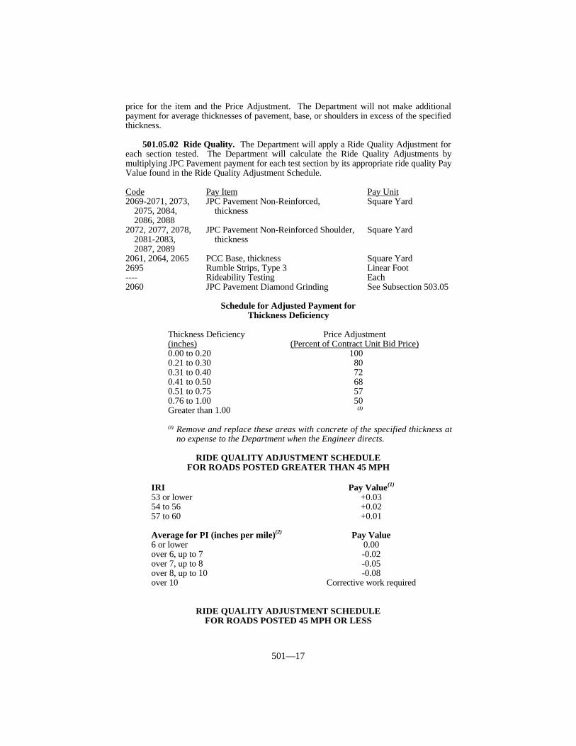
501—17
price for the item and the Price Adjustment. The Department will not make additionalpayment for average thicknesses of pavement, base, or shoulders in excess of the specifiedthickness.
501.05.02 Ride Quality. The Department will apply a Ride Quality Adjustment foreach section tested. The Department will calculate the Ride Quality Adjustments bymultiplying JPC Pavement payment for each test section by its appropriate ride quality PayValue found in the Ride Quality Adjustment Schedule.
Code Pay Item Pay Unit2069-2071, 2073, JPC Pavement Non-Reinforced, Square Yard
2075, 2084, thickness2086, 2088
2072, 2077, 2078, JPC Pavement Non-Reinforced Shoulder, Square Yard2081-2083, thickness2087, 2089
2061, 2064, 2065 PCC Base, thickness Square Yard2695 Rumble Strips, Type 3 Linear Foot---- Rideability Testing Each2060 JPC Pavement Diamond Grinding See Subsection 503.05
Schedule for Adjusted Payment forThickness Deficiency
Thickness Deficiency Price Adjustment(inches) (Percent of Contract Unit Bid Price)0.00 to 0.20 1000.21 to 0.30 800.31 to 0.40 720.41 to 0.50 680.51 to 0.75 570.76 to 1.00 50Greater than 1.00 (1)
(1) Remove and replace these areas with concrete of the specified thickness atno expense to the Department when the Engineer directs.
RIDE QUALITY ADJUSTMENT SCHEDULEFOR ROADS POSTED GREATER THAN 45 MPH
IRI Pay Value(1)
53 or lower +0.0354 to 56 +0.0257 to 60 +0.01
Average for PI (inches per mile)(2) Pay Value6 or lower 0.00over 6, up to 7 -0.02over 7, up to 8 -0.05over 8, up to 10 -0.08over 10 Corrective work required
RIDE QUALITY ADJUSTMENT SCHEDULEFOR ROADS POSTED 45 MPH OR LESS

501—18
IRI Pay Value(1)
56 or lower +0.0357 to 60 +0.0261 to 64 +0.01
Average for PI (inches per mile)(2) Pay Value8 or less 0.00over 8, up to 10 -0.02over 10, up to 12 -0.05over 12 Corrective work required
(1) Contractor may correct areas to achieve a positive adjustment. TheDepartment will perform additional requested testing and retesting forcorrective work at a cost of $150.00 per lane mile. The Department will deductcharges for requested additional testing and retesting for corrective work frommonies due on the Contract.
(2) The Department will apply the unit bid price adjustment to the total area of the1,000-foot section of the traffic lane represented by the Profile Index. TheDepartment will not make payment in excess of 50 percent for any main linepavement that has an average Profile Index in excess of 10 inches per mile (12inches per mile for 45 MPH or less) until the Contractor completes thecorrective work and the Department reprofiles and verifies that the averageProfile Index has been reduced to 10 inches per mile or less (12 inches per milefor 45 MPH or less)
The Department will consider payment as full compensation for all work requiredunder this section.

502—1
SECTION 502 JPC PAVEMENT 24/48/72
502.01 DESCRIPTION. Construct a single course of JPC pavement capable ofattaining a 3,500 psi compressive strength within 24 hours, 48 hours, or 72 hours.
502.02 MATERIALS AND EQUIPMENT. Conform to Subsection 501.02.
502.03 CONSTRUCTION. Conform to Subsection 501.03 with the followingexceptions and additions:
A) Proportioning and Requirements.
(1) The Department will allow up to 7-inch slump when using fixed forms provideda Type F or Type G admixture is used.
(2) The Department will allow a 94-lb reduction in the cement factor when usingType III cement.
When proposing an alternate mix design, meet only the following requirements:
1) attain a 3,500 psi compressive strength at the required time;2) furnish concrete having a minimum cement factor of 658 pounds per cubic yard
when using Type I cement or a minimum cement factor of 564 pounds per cubicyard when using Type III cement;
3) furnish concrete having an air content according to Subsection 601.03, Class Pconcrete.
B) Placing. When water is permitted, apply to the surface as a fog spray usingequipment that the Engineer approves. Place concrete within the mixture temperaturerange of 50 to 90 °F.
C) Curing and Protecting Pavement.
1) When overnight ambient temperatures are expected to be below 50 °F, cover theconcrete with one of the following:
a) one layer of closed-cell polystyrene foam protected by at least one layer ofplastic film;
b) 2 layers of burlap covered with one layer of 4-mil plastic;c) 3 inches of hay or straw covered with one layer of 4-mil plastic;d) a Department approved alternate.
2) When overnight ambient temperatures are expected to be below 40 °F, cover theconcrete with one of the following:
MODIFIED INGREDIENT PROPORTIONS AND REQUIREMENTS FORCLASS P CONCRETE FOR EARLY STRENGTH PAVEMENTS
Class P Maximum Maximum Minimum Required TimeModified Free Water Slump(1) Cement to Attain 3,500 psiMixture by W/C Factor(2) Compressive
Ratio Strength(lb/lb) (inches) (lb/yd3) (Hours)
JPCP/24 0.33 2 799 24JPCP/48 0.34 2 729 48JPCP/72 0.35 2 658 72
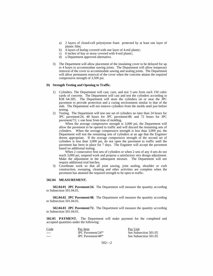
502—2
a) 2 layers of closed-cell polystyrene foam protected by at least one layer of
plastic film;b) 4 layers of burlap covered with one layer of 4-mil plastic;c) 6 inches of hay or straw covered with 4-mil plastic;d) a Department approved alternative.
3) The Department will allow placement of the insulating cover to be delayed for upto 4 hours to accommodate sawing joints. The Department will allow temporaryremoval of the cover to accommodate sawing and sealing joints. The Departmentwill allow permanent removal of the cover when the concrete attains the requiredcompressive strength of 3,500 psi.
D) Strength Testing and Opening to Traffic.
1) Cylinders. The Department will cast, cure, and test 3 sets from each 150 cubicyards of concrete. The Department will cast and test the cylinders according toKM 64-305. The Department will store the cylinders on or near the JPCpavement to provide protection and a curing environment similar to that of theslab. The Department will not remove cylinders from the molds until just beforetesting.
2) Testing. The Department will test one set of cylinders no later than 24 hours forJPC pavement/24; 48 hours for JPC pavement/48; and 72 hours for JPCpavement/72; ± one hour from time of molding.
When the average compressive strength is 3,000 psi, the Department willallow the pavement to be opened to traffic and will discard the remaining sets ofcylinders. When the average compressive strength is less than 3,000 psi, theDepartment will test the remaining sets of cylinders at an age that the Engineerdeems appropriate. If the average compressive strength of the second set ofcylinders is less than 3,000 psi, do not open the pavement to traffic until thepavement has been in place for 7 days. The Engineer will accept the pavementbased on additional testing.
When 2 consecutive first sets of cylinders or when 2 sets of any 4 sets do notreach 3,000 psi, suspend work and propose a satisfactory mix design adjustment.Make the adjustment in the subsequent mixture. The Department will notrequire additional trial batches.
3) Coordinate work so that all joint sawing, joint sealing, shoulder or curbconstruction, sweeping, cleaning and other activities are complete when thepavement has attained the required strength to be open to traffic.
502.04 MEASUREMENT.
502.04.01 JPC Pavement/24. The Department will measure the quantity accordingto Subsection 501.04.01.
502.04.02 JPC Pavement/48. The Department will measure the quantity accordingto Subsection 501.04.01.
502.04.03 JPC Pavement/72. The Department will measure the quantity accordingto Subsection 501.04.01.
502.05 PAYMENT. The Department will make payment for the completed andaccepted quantities under the following:
Code Pay Item Pay Unit---- JPC Pavement/24(1) See Subsection 501.05---- JPC Pavement/48(1) See Subsection 501.05

502—3
---- JPC Pavement/72(1) See Subsection 501.05---- Rideability Testing See Subsection 501.05
(1)When the Contract designates areas as “Must be opened on schedule” andthose areas do not attain the required compressive strength within thespecified time period, the Department will adjust the Contract unit price by theSchedule of Adjusted Payment for Delay of Opening.
Schedule for Adjusted Payment forDelay of Opening
Price AdjustmentDelay of Opening (Hours) (Percent of Contract Unit Bid Price)
JPCP/24 JPCP/48 JPCP/724 8 12 908 16 24 80
12 24 36 7016 32 48 6020 40 60 50
The Department will consider payment as full compensation for all work requiredunder this section.

503—1
SECTION 503 DIAMOND GRINDING JPC PAVEMENT
503.01 DESCRIPTION. Diamond grind existing JPC pavements. Eliminate faultingat joints and cracks, restore the ride quality to meet or exceed limits specified, and restoretexture to the entire pavement surface.
503.02 MATERIALS AND EQUIPMENT.
503.02.01 Grinding Machine. Furnish a self-propelled grinding machine withdiamond blades that is specifically designed to smooth and texture JPC pavement. Furnisha machine that is capable of cutting or planing at least 3 feet wide on each pass and thatdoes not encroach on traffic movement outside the work area.
503.02.02 Joint Sealer. Conform to Section 807. Use preformed or silicone rubber.
503.03 CONSTRUCTION.
503.03.01 Test Section. At the beginning of work, grind an initial test section atleast 3 feet wide and 100 feet long. The Engineer will evaluate the initial test section todetermine if the texture meets the requirements of this section. Modify the blade spacingor other features as necessary to produce the specified texture. Make similar modificationsthroughout the project to ensure acceptable surface texture.
503.03.02 Diamond Grinding. Grind the entire surface of the JPC pavementmainline. Grind ramps, tapers, acceleration and deceleration lanes, turn lanes, mediancrossovers, and bridge decks as the Contract specifies. Grind shoulders or gutters whennecessary for proper pavement drainage.
Grind in a longitudinal direction and parallel to the pavement centerline. Begin andend at lines normal to the pavement centerline. When the end of the cut is subject topublic traffic, grind a smooth transition from the smooth pavement to the non-groundpavement. Maintain a constant cross-slope between grinding extremities in each lane toensure positive lateral drainage. Overlap the edge of grinding passes by less than 2 inches.
503.03.03 Cleaning. Remove solid residue from the pavement surface before trafficor wind blows it. Perform a separate washing operation to remove residue that may causedust after the completion of grinding when the Engineer directs. Ensure that waste waterand residue do not flow across the pavement, into gutters, or into drainage structures.Dispose of waste water and residue as the Engineer approves.
503.03.04 Lighting. Provide lighting, as the Engineer approves, when grindingbetween dusk and dawn.
503.03.05 Joint Seals.
A) Resealing Existing Joints. After grinding is complete on areas adjacent to thejoints and after conforming to the ride quality requirements, clean and reseal thejoints according to Subsection 501.03.
B) Preserving Existing Joints Seals. After grinding is complete and when theEngineer directs, remove and replace any damaged seals with new seals. TheEngineer may require replacement of preformed compression joint seals whendamage penetrates the top void of the seal and replacement of silicone joint sealswhen the seal shows loss of bond with the sides of the joint or significant loss ofthe profile of the seal. Remove damaged seals for the full traffic lane width,thoroughly clean the joint, and install new seals according to Subsection501.03.18.

503—2
503.03.06 Pavement Marking. Remove existing pavement marking and providetemporary pavement markings according to Section 112 where the Contract specifies.
503.03.07 Texture. The Department will measure the dimensions of thelongitudinal grooves. If the dimensions are not within the following limits, makeadjustments to the grinding equipment to achieve the required texture:
Groove Dimension Value (inch)Width of grooves Between 0.09 and 0.130Width between grooves Between 0.08 and 0.125Height of groove (Peak to bottom) Between 0.031 and 0.063
503.03.08 Alignment Tolerances. The Department will measure the transverseslope of ground pavement with a straightedge placed normal to the centerline. If adepression or misalignment of slope greater than 0.25 inch in 12 feet occurs, adjust thegrinding equipment to correct the misalignment.
The Engineer will measure the alignment of the top of the pavement surface across thejoint and cracks. Correct all misalignments that exceed 0.063 inch by additional grinding.
503.03.09 Ride Quality. Conform to Section 410 with the following exceptions:
1) The lift thickness adjustment does not apply.2) All references are to JPC pavement in lieu of asphalt pavement.3) All references are to diamond grinding in lieu of paving.4) Achieve an IRI of 63 or less for each traffic lane with no individual one-mile
section having an IRI of greater than 76.5) Perform corrective work to achieve the required IRI by regrinding the entire
width of the traffic lane at areas having a low IRI. The Engineer may excludepavement areas where grinding alone will not correct deficiency.
6) The Department will create a strip chart when the test results show that the IRI isless than 3.80 or upon request for higher IRI values.
503.04 MEASUREMENT.
503.04.01 JPC Diamond Grinding. The Department will measure the quantity insquare yards. The Department will measure the width as the width shown on the typicalcross section of the Plans and the length horizontally along the centerline of each lane orramp. The Department will not measure corrective work for payment. The Departmentwill not measure the ride quality to calculate an adjusted unit price for this item of work.
503.04.02 Joint Sealing. The Department will measure Joint Sealing by linear feet.The Department will not measure removing existing joint material or cleaning joints forpayment but will consider them incidental to this item of work.
503.05 PAYMENT. The Department will make payment for the completed andaccepted quantities under the following:
Code Pay Item Pay Unit2060 JPC Pavement Diamond Grinding Square Yard8540 Joint Sealing Linear Foot
The Department will consider payment as full compensation for all work requiredunder this section.
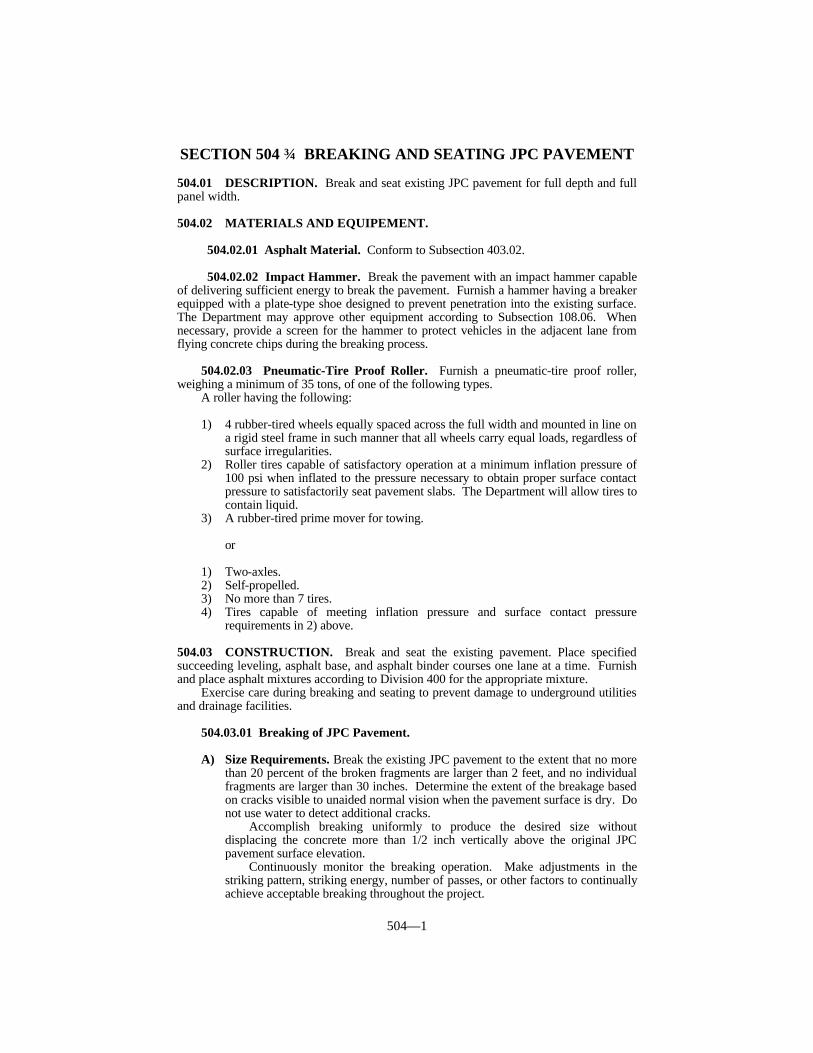
504—1
SECTION 504 BREAKING AND SEATING JPC PAVEMENT
504.01 DESCRIPTION. Break and seat existing JPC pavement for full depth and fullpanel width.
504.02 MATERIALS AND EQUIPEMENT.
504.02.01 Asphalt Material. Conform to Subsection 403.02.
504.02.02 Impact Hammer. Break the pavement with an impact hammer capableof delivering sufficient energy to break the pavement. Furnish a hammer having a breakerequipped with a plate-type shoe designed to prevent penetration into the existing surface.The Department may approve other equipment according to Subsection 108.06. Whennecessary, provide a screen for the hammer to protect vehicles in the adjacent lane fromflying concrete chips during the breaking process.
504.02.03 Pneumatic-Tire Proof Roller. Furnish a pneumatic-tire proof roller,weighing a minimum of 35 tons, of one of the following types.
A roller having the following: 1) 4 rubber-tired wheels equally spaced across the full width and mounted in line on
a rigid steel frame in such manner that all wheels carry equal loads, regardless ofsurface irregularities.
2) Roller tires capable of satisfactory operation at a minimum inflation pressure of100 psi when inflated to the pressure necessary to obtain proper surface contactpressure to satisfactorily seat pavement slabs. The Department will allow tires tocontain liquid.
3) A rubber-tired prime mover for towing.
or
1) Two-axles.2) Self-propelled.3) No more than 7 tires.4) Tires capable of meeting inflation pressure and surface contact pressure
requirements in 2) above.
504.03 CONSTRUCTION. Break and seat the existing pavement. Place specifiedsucceeding leveling, asphalt base, and asphalt binder courses one lane at a time. Furnishand place asphalt mixtures according to Division 400 for the appropriate mixture.
Exercise care during breaking and seating to prevent damage to underground utilitiesand drainage facilities.
504.03.01 Breaking of JPC Pavement.
A) Size Requirements. Break the existing JPC pavement to the extent that no morethan 20 percent of the broken fragments are larger than 2 feet, and no individualfragments are larger than 30 inches. Determine the extent of the breakage basedon cracks visible to unaided normal vision when the pavement surface is dry. Donot use water to detect additional cracks.
Accomplish breaking uniformly to produce the desired size withoutdisplacing the concrete more than 1/2 inch vertically above the original JPCpavement surface elevation.
Continuously monitor the breaking operation. Make adjustments in thestriking pattern, striking energy, number of passes, or other factors to continuallyachieve acceptable breaking throughout the project.

504—2
B) Test Section. Before breaking operations begin, the Engineer will designate atest section. Break the test section using varying energy and striking patterns.When necessary, repeat passes of the equipment over the pavement until the testsection is acceptably broken according to A) above. Use the extent of breakageof the test section as a guide for breaking the pavement on the remainder of theproject. The Engineer may require additional test sections at any time during thecourse of the work when sizes do not conform to the size requirements of A)above.
504.03.02 Seating of Broken JPC Pavement. After breaking, seat the brokenconcrete by rolling with a pneumatic-tire proof roller. Make at least 5 one-way passeswith a minimum 50-ton roller, or 7 one-way passes with a minimum 35-ton roller. Use arolling pattern that will ensure that the entire area of the broken pavement is well seatedand is thoroughly and uniformly compacted. Remove any large rocking fragments andfragments that are displaced more than 1/2 inch above the original pavement surfaceelevation after seating and fill the resulting void with asphalt and compact or tamp.
504.03.03 Placement of Edge Drains. When the Contract includes installation ofpavement edge drains, install the edge drains at least 2 weeks before breaking and seatingoperations.
504.03.04 Placement of Asphalt. Sweep the broken and seated pavement clean offoreign material using mechanical sweepers and hand brooms.
Place the asphalt base following the breaking and seating operation as closely aspractical according to Subsection 403.03. Do not allow the broken pavement to remainexposed more than 24 hours. If the broken pavement is exposed more than 24 hours,suspend the breaking operations until all broken existing pavement has been covered by atleast one course of asphalt base.
Make any required changes to the cross slope with the paving of the base courses.Cure the fist course of base at least 8 hours before placing the second course. Do not opena lane to public traffic until 2 courses of asphalt (not including leveling courses) are inplace. Offset the longitudinal joints in the asphalt 6 inches according to Subsection403.03.07.
Perform leveling and wedging according to Subsection 403.03.09 on top of the firstcourse of asphalt, and not on the existing pavement. However, at specific locations wherethe Engineer deems a substantial amount of leveling is necessary, level and wedge directlyon the broken and seated pavement. Correct deviations in the surface by leveling andwedging on each succeeding course unless the Engineer directs or approves in writing thatthe leveling and wedging be delayed until after placing the succeeding courses. Constructasphalt courses succeeding the first 2 courses according to the Contract.
504.04 MEASUREMENT.
504.04.01 Breaking and Seating Pavement. The Department will measure thequantity in square yards. The Department will measure the width as the actual width ofthe original JPC pavement, and the length as the horizontal length along the centerline ofeach roadway or ramp.
504.04.02 Leveling and Wedging. The Department will measure quantityaccording to Subsection 403.04.
504.04.03 Asphalt Mixtures. The Department will measure quantity according toSubsection 403.04 for the appropriate mixture.
504.05 PAYMENT. The Department will make payment for the completed andaccepted quantities under the following:

504—3
Code Pay Item Pay Unit2107 Breaking and Seating Pavement Square Yard0190 Leveling and Wedging, PG 64-22 See Subsection 403.05---- Asphalt Mixtures See Subsection 403.05
The Department will consider payment as full compensation for all work requiredunder this section.
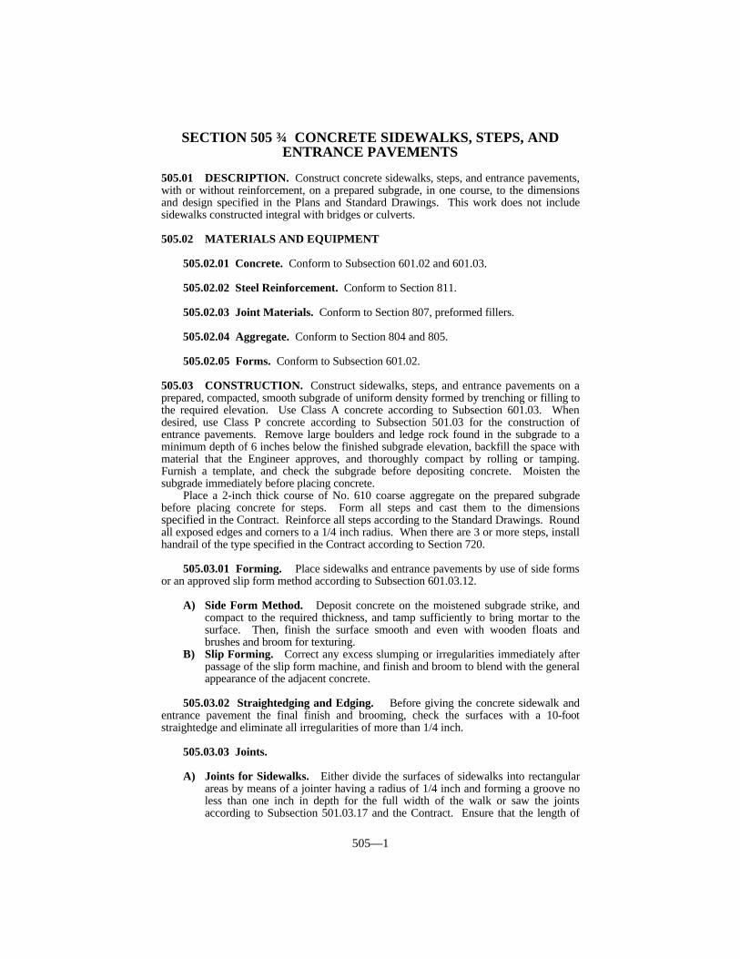
505—1
SECTION 505 CONCRETE SIDEWALKS, STEPS, ANDENTRANCE PAVEMENTS
505.01 DESCRIPTION. Construct concrete sidewalks, steps, and entrance pavements,with or without reinforcement, on a prepared subgrade, in one course, to the dimensionsand design specified in the Plans and Standard Drawings. This work does not includesidewalks constructed integral with bridges or culverts.
505.02 MATERIALS AND EQUIPMENT
505.02.01 Concrete. Conform to Subsection 601.02 and 601.03.
505.02.02 Steel Reinforcement. Conform to Section 811.
505.02.03 Joint Materials. Conform to Section 807, preformed fillers.
505.02.04 Aggregate. Conform to Section 804 and 805.
505.02.05 Forms. Conform to Subsection 601.02.
505.03 CONSTRUCTION. Construct sidewalks, steps, and entrance pavements on aprepared, compacted, smooth subgrade of uniform density formed by trenching or filling tothe required elevation. Use Class A concrete according to Subsection 601.03. Whendesired, use Class P concrete according to Subsection 501.03 for the construction ofentrance pavements. Remove large boulders and ledge rock found in the subgrade to aminimum depth of 6 inches below the finished subgrade elevation, backfill the space withmaterial that the Engineer approves, and thoroughly compact by rolling or tamping.Furnish a template, and check the subgrade before depositing concrete. Moisten thesubgrade immediately before placing concrete.
Place a 2-inch thick course of No. 610 coarse aggregate on the prepared subgradebefore placing concrete for steps. Form all steps and cast them to the dimensionsspecified in the Contract. Reinforce all steps according to the Standard Drawings. Roundall exposed edges and corners to a 1/4 inch radius. When there are 3 or more steps, installhandrail of the type specified in the Contract according to Section 720.
505.03.01 Forming. Place sidewalks and entrance pavements by use of side formsor an approved slip form method according to Subsection 601.03.12.
A) Side Form Method. Deposit concrete on the moistened subgrade strike, andcompact to the required thickness, and tamp sufficiently to bring mortar to thesurface. Then, finish the surface smooth and even with wooden floats andbrushes and broom for texturing.
B) Slip Forming. Correct any excess slumping or irregularities immediately afterpassage of the slip form machine, and finish and broom to blend with the generalappearance of the adjacent concrete.
505.03.02 Straightedging and Edging. Before giving the concrete sidewalk andentrance pavement the final finish and brooming, check the surfaces with a 10-footstraightedge and eliminate all irregularities of more than 1/4 inch.
505.03.03 Joints.
A) Joints for Sidewalks. Either divide the surfaces of sidewalks into rectangularareas by means of a jointer having a radius of 1/4 inch and forming a groove noless than one inch in depth for the full width of the walk or saw the jointsaccording to Subsection 501.03.17 and the Contract. Ensure that the length of
505—2
the rectangles formed does not exceed the width of the sidewalk beingconstructed.
When the sidewalk is constructed integral with the curb, ensure that thewidth and spacing of the joints conform to that in the curb. Round the edges ofthe sidewalk at all expansion joints with an approved edging tool to a 1/4 inchradius. Install 1/2-inch premolded expansion joint material to the full depth ofthe sidewalk where the sidewalk abuts any rigid structure or fixture, such ascurbs, columns, castings, buildings, and light standards.
B) Joints for Entrance Pavements. Construct 1/4-inch wide sawed contractionjoints in entrance pavements according to Subsection 501.03.17. Construct thesejoints at locations shown on the Standard Drawings. The Department will notrequire steel reinforcement in contraction joints. Saw the joints to a minimumdepth of 2 inches. Install 1/2-inch wide expansion joints where shown on theStandard Drawings. Seal both expansion joints and contraction joints accordingto Subsection 501.03.18 and the Standard Drawings.
505.03.04 Curing and Backfilling. Cure concrete sidewalks, steps, and entrancepavements according to Subsection 601.03.17.
After the concrete has set sufficiently, remove forms and backfill areas adjacent to theconcrete. Compact and grade the backfill.
505.04 MEASUREMENT.
505.04.01 Concrete Sidewalk. The Department will measure the quantity in squareyards.
505.04.02 Concrete Entrance Pavement. The Department will measure thequantity in square yards.
505.04.03 Class A Concrete for Steps. The Department will measure the quantityaccording to Subsection 601.04. The Department will not measure excavation, steelreinforcement, or crushed aggregate for steps for payment and will consider themincidental to this item of work.
505.04.04 Roadway Excavation. The Department will measure the quantityaccording to Subsection 204.04.
505.04.05 Embankment-In-Place. The Department will measure the quantityaccording to Subsection 206.04.
505.05 PAYMENT. The Department will make payment for the completed andaccepted quantities under the following:
Code Pay Item Pay Unit2719, 2720, 2723 Sidewalk, Thickness, Concrete Square Yard2101, 2099 Cement Concrete Entrance Square Yard
Pavement, Thickness2551 Concrete, Class A for Steps See Subsection 601.052200 Roadway Excavation See Subsection 204.052230 Embankment-In-Place See Subsection 206.05
The Department will consider payment as full compensation for all work requiredunder this section.

506—1
SECTION 506 CONCRETE CURBS AND GUTTERS
506.01 DESCRIPTION. Construct, on a prepared subgrade according to the StandardDrawings, concrete curb and gutter, concrete valley gutter, concrete header curb, andconcrete integral curb.
506.02 MATERIALS.
506.02.01 Concrete. Conform to Subsection 601.02 and 601.03.
506.02.02 Steel Reinforcement. Conform to Section 811.
506.02.03 Joint Fillers. Conform to Section 807, preformed fillers.
506.02.04 Forms. Conform to Subsections 501.02. and 601.02.
506.02.05 Fine Aggregate. Conform to Section 804.
506.02.06 Coarse Aggregate. Conform to Section 805.
506.03 CONSTRUCTION.
506.03.01 Header Curb, Valley Gutter, and Curb and Gutter (Combination).Use combination curb and gutter in conjunction with asphalt pavements. Constructcombination curb and gutter according to the typical section in the Plans. Use header curbin conjunction with either asphalt or JPC pavement where the depth of pavement is aminimum of one foot or where the thickness of asphalt pavement is variable. Constructheader curb before placing pavement. Construct valley gutter according to the Plans andStandard Drawings.
Prepare the foundation by excavating or constructing the embankment to the requiredsubgrade elevation on which the curb, gutter, or combination curb and gutter is to beplaced. Remove all soft, yielding, or otherwise unsuitable material, and replace it withstable materials according to Section 207, and compact and finish the subgrade to a firmeven surface.
Use Class A concrete according to Subsection 601.03. Place concrete either by use ofside forms or by an approved slip forming method according to Subsection 501.02.10.
When indicated or directed, form entrance and drainage openings of the requireddimensions through the curbs at the designated location.
Prepare the subgrade as required and moisten before placing concrete. Duringplacement, thoroughly spade the concrete and vibrate or tamp it until the mortar entirelycovers the surface and eliminate all honeycomb and voids. Place concrete so that noconcrete reaches initial set before placing the following lift. Strike off and float surfaces soall coarse aggregate is well below the surface.
Place reinforcing steel according to the details specified in the Contract. Constructcontraction joints as specified in Subsection 501.03.17 D).
Construct expansion joints at all breaks in alignment, at all drainage boxes and otherfixed objects, at the beginning and ending points of curves, and at the beginning, quarter,middle, and ending points of semicircular curves, except the Engineer will not requirejoints at the quarter points for semicircles having radii of 5 feet or less.
Give the top surfaces of curbs a uniform float finish and round edges according to theStandard Drawings. Correct all honeycombed areas by filling with mortar. Do not plaster.Finish the top and face of all curbs while the concrete is plastic by wetting and rubbingwith a carborundum brick or wooden block. Finish the face of header curbs to 2 inchesbelow the gutter line or the finished groundline. Before giving the concrete the final finish,check surfaces with a 10-foot straightedge and eliminate all irregularities of more than 1/4inch. Finish concrete to a smooth surface, presenting a uniform texture and color.
506—2
Cure the concrete according to Subsection 501.03.15.Construct precast curbs to the length and shape, and reinforce according to the
Standard Drawings. Cast, finish, and cure precast curbs according to Section 605.03. Setprecast curbs to conform to the line and grade specified in the Plans with tight joints. Fillall joints except expansion joints with mortar. When the precast curb is set, fill allremaining excavated areas with material that the Engineer approves in lifts not exceeding6 inches in depth and tamp.
506.03.02 Integral Curb. Use integral curb in conjunction with JPC pavementswhere a portion of the JPC pavement is the gutter. Construct according to Subsection506.03.01 except for the following:
1) Use either Class A concrete according to Subsection 601.03, or Class P concreteaccording to Subsection 501.03.
2) Construct integral curbs monolithic with the pavement or as a separate operationby anchoring to the pavement.
For integral curbs constructed monolithic with the pavement in a separateoperation from placement of the pavement concrete, place the curbs immediatelyfollowing completion of the pavement finishing operations and before theconcrete has taken its initial set. Do not exceed an elapsed time between placingconcrete in the pavement and in the curb of one hour. Obtain a thorough bondbetween the pavement and curb by roughening the surface of the pavementcovered by the curb by means of a trowel or wire brush. Place stirrups accordingto the Standard Drawings in the freshly finished concrete at intervals of 2 1/2 feetbefore placing the curb. Do not place stirrups closer than 3 inches to the centerof sawed construction joints.
When the curb is constructed as a separate operation, clean the surface of theconcrete in the pavement of all foreign material before placing concrete in thecurbs. Should it be necessary for stirrups to be bent in order to allow equipmentto pass over the bars at the beginning of a days run, bend the bars beforeinstallation.
3) Insert preformed joint filler, and cut it to conform to the cross section of the curb,in the curb directly over the expansion joint in the pavement while placing thecurb. Construct contraction joints at the same locations as those in the pavement.
4) Use side forms with a depth equal to that of the curb. Ensure that the forms arejoined neatly, fastened securely, and held rigidly in place by adequateconnections and bracing. Check curb forms for grade and alignment to the samedegree of accuracy required for pavement forms. After the concrete in the curbhas hardened sufficiently, but in no less than 6 hours after placement, remove theinside forms and finish the inside face of the curb to a uniform color and textureby rubbing with a wooden block or a carborundum brick. Correct anyhoneycomb or other surface defects by pointing with mortar of the sameproportions of cement and sand used in the concrete.
To obtain a neat line on the thin edge of the integral curb lip, construct by placing aone-inch by 4-inch board, at least 10 feet long and surfaced on all 4 sides, on the concreteslab to act as a guide when forming the curb, or use other approved methods.
Seal all pavement joints according to Subsection 501.03.17 before integral curb isconstructed. If the integral curb is constructed monolithically with the pavement, seal thecurb in the same manner as the pavement.
506.04 MEASUREMENT.
506.04.01 Header Curb. The Department will measure the quantity in linear feetalong the face of the curb.
506.04.02 Valley Gutter. The Department will measure the quantity in linear feet
506—3
along the flowline of the gutter.
506.04.03 Curb and Gutter (combination). The Department will measure thequantity in linear feet along the flowline of the gutter.
506.04.04 Integral Curb. The Department will measure the quantity in linear feetalong the top of the curb.
506.05 PAYMENT. The Department will make payment for the completed andaccepted quantities under the following:
Code Pay Item Pay Unit1875-1877, 1880, 1885, 1890, 1891 Type, Header Curb Linear Foot1895 Valley Gutter Linear Foot1810, 1811, 1815, 1820, 1821, 1825 Type, Curb and Gutter Linear Foot1830, 1831, 1840, 1841, 1845, 1847 Type, Integral Curb Linear Foot
The Department will consider payment as full compensation for all work requiredunder this section.
507—1
SECTION 507 CONCRETE MOUNTABLE MEDIAN ANDSTANDARD BARRIER MEDIAN
507.01 DESCRIPTION. Prepare the foundation for the mountable median or standardbarrier median, furnish, place, consolidate, finish, and cure concrete, and construct alljoints necessary for completing the work.
507.02 MATERIALS.
507.02.01 Concrete. Conform to Subsection 601.02 and 601.03.
507.02.02 Steel Reinforcement. Conform to Section 811.
507.02.03 Joint Material. Conform to Section 807, preformed fillers.
507.02.04 Forms. Conform to Subsection 601.02.
507.03 CONSTRUCTION. Construct concrete mountable medians or standard barriermedians on the accepted prepared subgrade, or the completed and accepted base course orold pavement. Use Class A concrete according to Subsection 601.03 or Class P concreteaccording to Subsection 501.03. When required, place dowel bars according to theContract. Place concrete either by use of side forms or by an approved slip formingmethod according to Subsection 601.03.12.
When constructing medians in conjunction with JPC pavement, construct transversejoints at the same intervals and locations as joints in the adjacent pavement. Whenconstructing medians in conjunction with asphalt pavement, space transverse joints atintervals of 30 feet or less to provide uniform spacing. Construct all median joints aseither 1/2-inch expansion joints filled with preformed joint filler or 1/8-inch sawed joints.When sawing, construct median joints according to Subsection 501.03.17. The Engineerwill not require steel dowels in either type of joint.
Cure concrete placed in the median according to Subsection 501.03.15.
507.04 MEASUREMENT.
507.04.01 Standard Barrier Median. The Department will measure the quantity insquare yards.
507.04.02 Mountable Median. The Department will measure the quantity in squareyards.
507.05 PAYMENT. The Department will make payment for the completed andaccepted quantities under the following:
Code Pay Item Pay Unit1915-1923 Standard Barrier Median, Type Square Yard1935-1950 Mountable Median, Type Square Yard
The Department will consider payment as full compensation for all work requiredunder this section.
508—1
SECTION 508 PERMANENT CONCRETE MEDIANBARRIERS
508.01 DESCRIPTION. Prepare the foundation for the median barrier; furnish, place,consolidate, finish, and cure the barrier; construct all transverse joints; construct otherincidentals necessary to complete the work; and attach delineators and other appurtenanceswhen specified in the Contract.
508.02 MATERIALS AND EQUIPMENT.
508.02.01 Concrete. Conform to Subsection 601.02 and 601.03.
508.02.02 Steel Reinforcement. Conform to Section 811.
508.02.03 Joint Material. Conform to Section 807, preformed fillers.
508.02.04 Dowel Bars. Conform to Section 811.
508.02.05 Tie Bars for Precast Sections. Conform to Section 811.
508.02.06 Mortar Sand. Conform to Section 804.
508.02.07 Cement. Conform to Section 801.
508.02.08 Water. Conform to Section 803.
508.02.09 Masonry Coating. Conform to Section 828.
508.02.10 Delineators for Barriers. Use Stimsonite Marker 962, AKT CorporationMarker No. 181, or a Department approved equal.
508.02.11 Forms. Conform to Subsection 601.02. In addition to the requirementsfor slip forms, use a slip form or extrusion machine that is equipped with automaticguidance controls capable of sensing grade and alignment from an outside referenceconsisting of a taut line or wire.
508.03 CONSTRUCTION. Construct concrete median barriers of each type to thelines, grades, cross section, and details specified in the Plans and Standard Drawings. UseClass A concrete according to Subsection 601.03. When it is necessary to transition theconcrete median barrier into a section different from the uniform section specified in thePlans, such as at a bridge pier, sign pedestal, or bridge end wall, do so in a smooth,uniform manner as shown on the Standard Drawings. Provide concrete median barrierthat are precast, cast-in-place using fixed forms, or slip formed according to Subsection601.03.12.
Bevel the upper longitudinal edge of the barrier 7/8 inch, or construct it to a radiussatisfactory to the Engineer.
When required, construct items such as delineators and conduit according to theContract. Secure conduit to prevent movement.
Cure cast-in-place concrete median barriers according to Subsection 501.03.15. Usethe same method of curing on each continuous section of the barrier. Cure precast concretemedian barriers according to Subsection 605.03.05.
508.03.01 Fixed Form Construction. Construct 1/2-inch transverse expansionjoints throughout the entire cross section at uniform intervals of no less than 15 feet orgreater than 25 feet. For construction in conjunction with JPC pavements, locatetransverse expansion joints so that a joint occurs at the same stations as that of the rigid
508—2
pavement transverse joints. Construct additional transverse contraction joints in the barrierif necessary to maintain the 15 to 25-foot interval. Fill all transverse and longitudinaljoints with preformed joint filler. Construct one-inch expansion joints over expansionjoints in rigid pavement or base. Construct 1/2-inch expansion joints when the barrierabuts a bridge and at all box inlets, lamp posts, sign posts, and similar structures thatproject through, into, or against the concrete median barrier.
The Department will allow construction of joints according to Subsection 508.03.02.Conform to the tolerance requirements of Appendix A, Tabulation of Construction
Tolerances. Uniformly coat the median barriers with masonry coating.
508.03.02 Slip Form Construction. Suspend reference lines from supports set atintervals no greater than 10 feet on vertical and horizontal curves or 25 feet on uniformgrades or tangents. Do not use ski or shoe sensors to reflect the grade of the subgradeunless the ski or shoe can ride on the completed pavement surface.
Provide a construction joint between the base and the barrier. Construct a 2 by 4-inchkey, either depressed or raised, in the base. Insert steel dowels in the plastic concreteimmediately behind the slip form machine at the locations shown on the StandardDrawing. Place the base using slip form or extrusion methods.
Immediately repair all surface pits larger than 1/2 inch in diameter and all gougesbehind the slip form machine. The Engineer will not require further finishing, other than alight longitudinal brushing or brooming.
Provide short sections, such as sections adjacent to structures, terminal sections, etc.that are cast using fixed forms.
Construct one-inch transverse expansion joints at intervals no greater than 500 feet.Construct one-inch transverse expansion joints over all transverse expansion joints in rigidpavement or base. Construct 1/2-inch expansion joints when the barrier abuts a bridgeand at all box inlets, lamp posts, and similar structures that project through, into, oragainst the concrete median barrier. Fill all transverse and longitudinal joints withpreformed joint filler.
Construct 1/8-inch transverse contraction joints 2 inches deep at uniform intervals of20 to 30 feet. Make contraction joints by cutting into the plastic concrete using an edgingtool and trowel, using removable inserts, or sawing. When sawing contraction joints, sawas soon as practical after the concrete has set sufficiently to preclude raveling, and beforeany shrinkage cracking occurs in the concrete. The Engineer will not require sealing ofcontraction joints.
Construct construction joints as one-inch expansion joints. When constructing aconcrete median barrier over JPC pavement or base, locate transverse joints in the barrierto match transverse joints in the pavement or base. Construct additional transversecontraction joints in the barrier if necessary to maintain the 20 to 30-foot interval specifiedabove. When constructing transverse joints in the JPC pavement or base at variableintervals, adjust the joint interval in the wall to match the joint interval in the pavement orbase and construct additional joints as necessary to avoid exceeding the 30-foot maximuminterval.
Conform to the tolerance requirements of Appendix A, Tabulation of ConstructionTolerances
508.03.03 Precast Construction. Construct precast units according to Section 605and approved drawings. Place the precast units on a bed of mortar, and trim and discardexcess mortar. Uniformly coat the median barriers with masonry coating.
When precast concrete median barriers are specified or allowed for installation on anexisting facility, anchor them as the Plans specify.
When using precast units, cast short sections, transitions, terminal sections, and othersupplemental sections using fixed forms.
When casting threaded inserts into the barrier for use in lifting, protect the inserts byinstalling a solid, full-length, threaded, plastic bolt, coated with waterproof grease. Installthe bolt immediately after manufacturing the barrier section. Leave the bolt in place at alltimes while the barrier is in storage or in service, except when using the insert for lifting.

508—3
Entirely fill joints between units, including the 2 by 10-inch groove, with groutcomposed of one part mortar sand and 2 parts cement with enough water to make themixture plastic.
When the barrier abuts a bridge or other rigid structure, cut off the tie bars or fill thegroove with grout, as applicable, and install 1/2-inch preformed joint filler in the joints.
Install 1/2-inch preformed joint filler at all box inlets, lamp posts, sign posts, andsimilar structures that project through, into, or against the concrete median barrier.
Conform to the tolerance requirements for cast-in-place construction of Appendix A,Tabulation of Construction Tolerances.
Ensure that all concrete median barrier are uniform in appearance, and true to line andgrade. Repair or remove and replace all portions of the barrier that are not within thespecified tolerances, or precast units that cannot be correctly installed.
508.04 MEASUREMENT.
508.04.01 Concrete Median Barrier. The Department will measure the quantity inlinear feet along the top centerline of the barrier. The Department will not measurefurnishing, installing, or maintaining lifting devices in precast median barriers for paymentand will consider them incidental to this item of work. The Department will not measureportions of the barrier that are not within the specified tolerances, precast units that are notcorrectly installed, or damaged units.
508.04.02 Concrete Terminal Sections. The Department will measure the quantityby each individual unit.
508.04.03 Delineators for Barriers. The Department will measure the quantity byeach individual unit.
508.04.04 Masonry Coating. The Department will measure the quantity accordingto Subsection 601.04.
508.05 PAYMENT. The Department will make payment for the completed andaccepted quantities under the following:
Code Pay Item Pay Unit1953,1955, 1967, Concrete Median Barrier, Type Linear Foot
1988, 1989, 1992,19991956-1957 Concrete Terminal Section, Type Each1984, 1985 Delineator for Barrier, Color Each2998 Masonry Coating See Subsection 601.05
The Department will consider payment as full compensation for all work requiredunder this section.
509—1
SECTION 509 TEMPORARY CONCRETE MEDIANBARRIERS
509.01 DESCRIPTION. Furnish, install, maintain, and remove temporary precastconcrete median barriers. The Department will furnish the concrete median barriers whenspecified in the Contract.
The Department may allow the use of similar units that conform to the typical featuresdepicted by the Standard Drawings when the Engineer approves.
509.02 MATERIALS.
509.02.01 Concrete. Conform to Subsection 601.02 and 601.03.
509.02.02 Steel Reinforcement. Conform to Section 811.
509.02.03 Connector Bar Pins. Conform to ASTM A 36. Galvanize after formingaccording to AASHTO M 111.
509.02.04 Top Connectors. Conform to ASTM A 36. Galvanize after formingaccording to AASHTO M 111.
509.02.05 Bottom Connectors. Conform to ASTM A 36. Galvanize according toAASHTO M 111 after forming.
509.02.06 Tack Welding. Conform to Subsection 605.03.04.
509.02.07 Delineators for Barriers. Use either Stimsonite Marker 962, AKTCorporation Marker No. 181, or a Department approved equal.
509.03 CONSTRUCTION. Construct concrete median barriers according to Section605 and the Standard Drawings. Use Class A concrete and provide all concrete with anordinary surface finish according to Subsection 601.03.18. Place delineators according tothe Standard Drawings.
Lift and place the barrier units using a 2 point pickup, or another approved method.Do not lift units by the connectors. When casting threaded inserts into the barrier for usein lifting, protect the inserts by installing a solid, full-length, threaded, plastic bolt, coatedwith waterproof grease. Install the bolt immediately after manufacturing the barriersection. Leave the bolt in place at all times while the barrier is in storage or in service,except when using the insert for lifting.
Do not use any unit which has been cracked, chipped, scarred, or otherwise damagedor disfigured unless the Engineer approves.
Install the units at the locations specified in the Plans, and connect them in themanner detailed on the Plans and Standard Drawings. Keep delineators clean and providereplacement delineators when necessary. For all units in a continuous run, use units of thesame type and height, and provide a smooth transition. Replace all units damaged afterinstallation with an undamaged unit. When the units are no longer needed, remove theunits from the project. Take ownership of all units except Department furnished units.Transport Department furnished units to the location specified in the Contract.
509.04 MEASUREMENT.
509.04.01 Temporary Concrete Median Barrier. The Department will measurethe quantity furnished, installed, maintained, and removed by multiplying the nominallength of each unit in linear feet by the number of units. The Department will measureunits installed to replace units damaged by traffic. The Department will not measure thedisposal of units or units installed to replace units damaged by construction operations for

509—2
payment and will consider them incidental to this item of work. The Department will notmeasure furnishing, installing, or maintaining lifting devices for payment and willconsider them incidental to this item of work.
509.04.02 Install Temporary Concrete Median Barrier. The Department willmeasure the quantity, installed, maintained, and removed by multiplying the nominallength of each unit in linear feet by the number of units. The Department will furnish thebarrier. The Department will measure units installed to replace units damaged by traffic.The Department will not measure the disposal of units or units installed to replace unitsdamaged by construction operations for payment and will consider them incidental to thisitem of work. The Department will not measure furnishing, installing, or maintaininglifting devices for payment and will consider them incidental to this item of work.
509.04.03 Relocate Temporary Concrete Median Barrier. The Department willmeasure the quantity relocated by multiplying the nominal length of each unit in linear feetby the number of units.
509.04.04 Delineator for Barrier. The Department will measure the quantity by theindividual unit, including replacement units.
509.05 PAYMENT. The Department will make payment for the completed andaccepted quantities under the following:
Code Pay Item Pay Unit3171 Concrete Barrier Wall Type, 9T(1) Linear Foot1992 Install Temporary Concrete Median Barrier (2) Linear Foot2003 Relocate Temporary Concrete Median Barrier Linear Foot1984, 1985 Delineator for Barrier, Color Each
(1)The Department will pay 90 percent of the quantity upon satisfactoryinstallation of the units. The Department will pay the remaining 10 percentupon removal of the units from the project or upon placement to their finallocation.
(2)The Department will pay 75 percent of the quantity upon satisfactoryinstallation of the units. The Department will pay the remaining 25 percentupon removal of the units from the project or upon placement to their finallocation.
The Department will consider payment as full compensation for all work requiredunder this section.

510—1
SECTION 510 SEALING AND PATCHING CONCRETEWITH EPOXY RESIN
510.01 DESCRIPTION. Seal concrete surfaces, except JPC pavement, with an epoxyresin seal, and patch concrete surfaces, except JPC pavement, with an epoxy resin mortarpatch. Fill low areas with the patch material.
510.02 MATERIALS AND EQUIPMENT.
510.02.01 Epoxy Resin. Conform to Section 826.
510.02.02 Mortar Sand. Conform to Section 804.
510.02.03 Sand for Epoxy Seal Coats. Conform to Section 804.
510.02.04 Sandblasters. Provide sandblasters that are equipped with traps toprevent water or oil from being deposited on the surface.
510.02.05 Drills. Provide rotary, electric, 1/2-inch drills with a paddle or othermixing devices approved by the Engineer.
510.03 CONSTRUCTION. Allow new concrete to cure at least 14 calendar daysbefore applying any epoxy sealant or epoxy mortar patch. Do not apply to JPC pavement.Seal and patch JPC pavement as specified in the Contract. Ensure that the surfacetemperature of concrete surfaces to be sealed or patched is at least 60 °F. In cool weather,provide artificial heat using space heaters or infrared heaters. When providing artificialheat, maintain a surface temperature between 60 and 90 °F until the epoxy seal or epoxymortar patch has cured.
510.03.01 Preparation of Concrete Surface for Sealing or Patching. Prepareconcrete surfaces to be epoxy sealed or epoxy mortar patched by removing all laitance,deteriorated concrete, and deposits of oil, grease, and other adherent foreign materials.Remove oil, grease, and other adherent foreign materials using solvents, heavy detergents,or mechanical means such as scraping. Then, prepare the surfaces by grinding,sandblasting, retexturing, or chipping to remove all laitance and unsound concrete.Immediately before applying the epoxy seal or epoxy mortar patch, remove all dust, grit,and debris from the surface.
510.03.02 Mixing Epoxy Resin. Thoroughly stir the contents of the separatepackages containing component A and component B before combining the 2 components.Do not use the same mixer or paddle to mix component A as is used to mix component B.Combine the 2 components in a clean metal or polyethylene vessel. Combine thecomponents in the proportions and mix them according to the manufacturer’srecommendations. Only mix the material in quantities that can be used within the pot lifeof the mixture.
510.03.03 Mixing Epoxy Mortar for Patching. Establish the proportions of epoxyresin and mortar sand for the epoxy mortar mixture according to the manufacturer’sinstructions. Mix the epoxy mortar with a drill equipped for mixing. Gradually addmortar sand to the epoxy resin, and continue mixing the materials to obtain a uniformmixture.
510.03.04 Application of Epoxy Mortar for Patching. Prime areas to be patchedimmediately before placing the epoxy mortar. Thoroughly brush or scrub the epoxy resinfor the prime onto the prepared surface to be patched. Then place the epoxy mortar overthe primed area. Tamp, rod, and consolidate the epoxy mortar into place to exclude
510—2
internal voids within the mortar mixture. Level or finish the mortar surface to the specifiedsurface. Finish or treat the surface to conform to the surface texture of the concretesurrounding the patched area.
After the patch has cured, broom, vacuum, or blow away all loose material from thearea, and remove it from the pavement or deck. Do not allow traffic on the patched areasuntil the resinous material has hardened for the amount of time specified in themanufacturer’s specifications.
510.03.05 Epoxy Seal Coat. Place the epoxy seal coat and the sand for the epoxyseal coat according to the manufacturer’s instructions.
510.04 MEASUREMENT. The Department will not measure concrete sealing orpatching for payment and will consider them incidental to the bid item being patched orsealed.
510.05 PAYMENT. The Department will not make payment for concrete sealing orpatching.
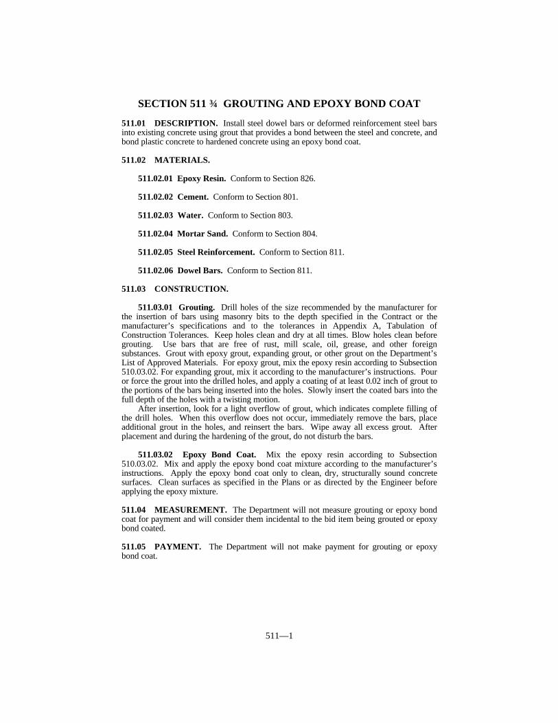
511—1
SECTION 511 GROUTING AND EPOXY BOND COAT
511.01 DESCRIPTION. Install steel dowel bars or deformed reinforcement steel barsinto existing concrete using grout that provides a bond between the steel and concrete, andbond plastic concrete to hardened concrete using an epoxy bond coat.
511.02 MATERIALS.
511.02.01 Epoxy Resin. Conform to Section 826.
511.02.02 Cement. Conform to Section 801.
511.02.03 Water. Conform to Section 803.
511.02.04 Mortar Sand. Conform to Section 804.
511.02.05 Steel Reinforcement. Conform to Section 811.
511.02.06 Dowel Bars. Conform to Section 811.
511.03 CONSTRUCTION.
511.03.01 Grouting. Drill holes of the size recommended by the manufacturer forthe insertion of bars using masonry bits to the depth specified in the Contract or themanufacturer’s specifications and to the tolerances in Appendix A, Tabulation ofConstruction Tolerances. Keep holes clean and dry at all times. Blow holes clean beforegrouting. Use bars that are free of rust, mill scale, oil, grease, and other foreignsubstances. Grout with epoxy grout, expanding grout, or other grout on the Department’sList of Approved Materials. For epoxy grout, mix the epoxy resin according to Subsection510.03.02. For expanding grout, mix it according to the manufacturer’s instructions. Pouror force the grout into the drilled holes, and apply a coating of at least 0.02 inch of grout tothe portions of the bars being inserted into the holes. Slowly insert the coated bars into thefull depth of the holes with a twisting motion.
After insertion, look for a light overflow of grout, which indicates complete filling ofthe drill holes. When this overflow does not occur, immediately remove the bars, placeadditional grout in the holes, and reinsert the bars. Wipe away all excess grout. Afterplacement and during the hardening of the grout, do not disturb the bars.
511.03.02 Epoxy Bond Coat. Mix the epoxy resin according to Subsection510.03.02. Mix and apply the epoxy bond coat mixture according to the manufacturer’sinstructions. Apply the epoxy bond coat only to clean, dry, structurally sound concretesurfaces. Clean surfaces as specified in the Plans or as directed by the Engineer beforeapplying the epoxy mixture.
511.04 MEASUREMENT. The Department will not measure grouting or epoxy bondcoat for payment and will consider them incidental to the bid item being grouted or epoxybond coated.
511.05 PAYMENT. The Department will not make payment for grouting or epoxybond coat.

512—1
SECTION 512 HOOK BOLTS WITH EXPANSIONANCHORS
512.01 DESCRIPTION. Furnish and install epoxy coated hook bolts with expansionanchors for use in JPC pavement widening or concrete culvert extensions.
512.02 MATERIALS.
512.02.01 Hook Bolts with Expansion Anchors. Conform to Section 811. Inaddition, ensure that the installed bolts, when tested just before placement of the adjoiningconcrete, can resist a pull-out load of 9,000 pounds.
512.02.02 Epoxy Coating Material. Conform to Section 811.
512.03 CONSTRUCTION. Epoxy coat and install hook bolts according to theinstallation requirements for epoxy coated steel reinforcement bars in Subsection 602.03and the Standard Drawings. Install hook bolts with expansion anchors at the locationspecified in the Plans or directed by the Engineer according to the manufacturer’sinstructions.
512.04 MEASUREMENT.
512.04.01 Hook Bolts with Expansion Anchors. The Department will measure thequantity by each individual unit. The Department will not measure epoxy coating forpayment and will consider it incidental to this item of work.
512.05 PAYMENT. The Department will make payment for the completed andaccepted quantities under the following:
Code Pay Item Pay Unit2587 Hook Bolt with Expansion Anchor Each
The Department will consider payment as full compensation for all work requiredunder this section.

DIVISION 600
STRUCTURES ANDCONCRETE

601—1
SECTION 601 CONCRETE
601.01 DESCRIPTION. Use concrete consisting of a mixture of cement, fineaggregate, coarse aggregate, and water, with admixtures as specified, combined in theproportions and mixed to the consistency specified, when forming or casting to dimensionsspecified in the Plans or as the Engineer directs. Provide the materials, materialproportions, equipment, and construction methods necessary to ensure that the concreteproduced conforms to the Contract. Structural concrete is concrete for structures such asbridges, culverts, and retaining walls. Non-structural concrete is concrete for non-structural items such as sidewalks, entrances, curb and gutter, and roadway medianbarrier.
601.02 MATERIALS AND EQUIPMENT.
601.02.01 Steel Reinforcement. Conform to Section 811.
601.02.02 Cement. Conform to Section 801. Use Type I cement. The Departmentwill allow the use of Type IA, Type IP, Type IPA, Type IS, Type I(SM), Type II, Type IIA,and Type III when the Engineer approves. The Engineer will condition his approval uponsatisfactory means of storage and handling to ensure the ready identification of thesecements when used in portions of the work. If unsatisfactory test results are obtainedusing Types IA, IP, IPA, IS, I(SM), II, IIA, or III cement, complete the work using Type Icement. Do not intermix cement types in any structural unit.
601.02.03 Admixtures. Conform to Section 802. Use air-entraining and waterreducing admixtures in all classes of concrete. Water reducing admixtures are not requiredwhen slip forming is used for concrete placement. Use other admixtures when theEngineer directs or approves.
601.02.04 Water. Conform to Section 803.
601.02.05 Fine Aggregate. Conform to Section 804.
601.02.06 Coarse Aggregate. Conform to Section 805.
601.02.07 Joint Materials. Conform to Section 807.
601.02.08 Structural Steel. Conform to Section 812.
601.02.09 Miscellaneous Metals. Conform to Section 813.
601.02.10 Concrete Curing Materials. Conform to Section 823.
601.02.11 Masonry Coating. Conform to Section 828.
601.02.12 Mineral Admixtures. Conform to Section 844.
601.02.13 Forms. Provide forms that are mortar tight, true to the dimensions, lines,and grades of the structure, and of sufficient strength to prevent appreciable deflectionduring placing concrete.
A) Form Panels. Form panels are continuous sections of form facing materialunbroken by joint marks, against which concrete is placed. For exposed surfaces,use form panels of plywood conforming to U.S. Product Standard PS-1 forExterior B-B (Concrete Form) Class I plywood or any material other thanplywood that will produce an equivalent smooth uniform concrete surface.
601—2
B) Plywood Forms. Ensure that plywood forms are at least 3/4 inch thick.C) Plastic Forms. Conform to the manufacturer’s specifications.D) Plastic Lined Forms. Conform to the manufacturer’s specifications.E) Metal Forms. Use metal forms of such thickness that the forms will remain true
to shape. Do not use metal forms that do not present a smooth surface or line upproperly.
F) Stay-In-Place Metal Forms. Conform to the following requirements:
1) Forms and Supports. Fabricate permanent steel bridge deck forms andsupports from steel conforming to ASTM A 653, Grades A through E, andhaving a zinc coating class of G 165 according to ASTM A 924. Use formshaving a minimum thickness of 22 gage.
2) Fastener Hardware. For miscellaneous fastener hardware (bolts, nuts, metalscrews, and washers), provide common stock hardware items with a zinccoating equal to or better than that required by ASTM A 153.
3) Coarse Aggregate. Conform to the requirements of Section 805.04.01 for allcoarse aggregate used in concrete for bridge decks and barrier walls whenusing permanent steel bridge deck forms.
4) Precast Beam Hardware. Provide all deck and overhang support hardwarethat is cast into precast beam tops with a zinc or epoxy coating of acommercial quality grade.
5) Anchor Legs. To anchor angle weld tabs, use straight anchor legscontaining a hole having a 1 1/8-inch minimum diameter. If necessary,incline the anchor leg to vertical.
G) Plank Forms. Use plank forms having a minimum nominal thickness of 1 1/2inches.
H) Form Oil. Provide a commercial quality form oil or other equivalent coating thatallows ready release of the forms and does not discolor the concrete or isdetrimental to masonry coating.
I) Form Fasteners. Use Engineer approved form fasteners.J) Chamfer Strips. Only use chamfer strips that are no less than 3/4 by 3/4 inch.
601.02.14 Scales. For weighing water, aggregates, cement, and mineral admixtures,provide either beam, springless dial, or electronic load cell type scales, designed as anintegral unit of the batching plant. When checked under static loads, maintain theaccuracy of the scales to within 0.5 percent of the net load on the scales. The net load onthe scales is the total weight of the actual test weights used in the accuracy determination.Use enough actual test weights to at least equal the weight necessary to check the cementscales to the net load required for a normal size batch. The Department will allow the useof aggregates in combination with test weights to obtain the accuracy determination ofaggregate scales in the higher ranges.
Provide dial scales having a minimum of 1,000 graduations with a clear intervalbetween graduation marks of 0.03 inch or more.
Provide beam scales having a graduation interval not greater than 0.1 percent of thescale capacity with a clear interval of 0.03 inch or more.
Provide scales that are sensitive enough to discern movement due to the addition tothe scales of a weight equal to 0.1 percent of the scale capacity under load when the scalesare not connected for automatic operation, or equal to 0.2 percent when the scales areconnected for automatic operation.
Except for small batches of concrete for headwalls, box inlets, finishing up operations,etc., use a batch size that exceeds 30 percent of the capacity of the scales.
Equip each beam scale with an auxiliary dial or “telltale” that will indicate to theoperator that the required load in the hopper is being approached. The device shall show aminimum of 4 percent of the net rated capacity of the largest beam for underweight and3 percent for overweight. Ensure that the indicator registers any movement of the beam.
601—3
Provide dial scales with suitable markers capable of being set to indicate the correctposition of the dial indicator for predetermined loads. Enclose the dial in a glass-facedcase for protection against dust.
Ensure that all weighing and indicating devices are in full view of and readable by theoperator while charging the hopper, and provide the operator with convenient access to allcontrols.
Have all scales inspected and certified before use and whenever the Engineer maydeem necessary to confirm the accuracy of the scales. Ensure that an inspection of thescales has been made within the preceding 6 months at any time a plant is supplyingconcrete to a Department construction project. Have a representative of a commercialscales company certified by the Division of Weights and Measures inspect and certify thescales. After the inspection and certification, only make adjustments or changes in theweighing mechanism at the direction of the Engineer. Keep all exposed fulcrums, clevises,and similar working parts of the scales clean at all times.
Furnish all weights and other equipment necessary for testing and calibrating thescales.
601.02.15 Batching Plant Equipment. Ensure that the plant conforms to all safety,health, and sanitation requirements specified in Subsection 107.01.01. Supply thebatching plant with bins, weighing hoppers, and scales for the fine aggregate, each size ofcoarse aggregate, bulk cement, and mineral admixtures. The Department will allowweighing of cementitous material cumulatively. For the bulk cement, provide scalesseparate and distinct from those used for aggregate. Install and maintain the batchingplant in a manner to provide accurate operations at all times. Only use weatherproofequipment for unloading cement, and protect the storage, weighing, and batchingequipment for cement from the weather at all times.
Provide bins with separate compartments of sufficient capacity for each size of fineand coarse aggregate, and for bulk cement. Design each compartment to dischargeefficiently and freely into the weighing hopper.
Provide a means of control so that when the quantity desired is being approached, thematerial may be added slowly and shut off with precision.
Use freely suspended weighing hoppers that do not affect the free movement of theweighing mechanism. Enclose the cement weigh hopper to prevent the loss of cementduring weighing, and provide it with an approved device to transfer the cement to thebatch trucks or the mixer. Construct all hoppers to eliminate leakage and the accumulationof tare materials, and to discharge completely. Provide any hopper that does not dischargesatisfactorily with a vibrator having the frequency and power necessary to effect completedischarge.
601.02.16 Mixers.
A) Batch Mixer. Furnish a batch mixer of an approved size and type specified topositively ensure uniform distribution of materials throughout the mass, and toensure discharge of the entire batch without segregation. Do not use any mixershaving a rated capacity of less than one bag batch. Equip the mixer withadequate water storage and a device for accurately measuring and automaticallycontrolling water discharge into each batch. Provide a mechanical device tocontrol time of mixing for each batch and to automatically prevent discharge ofthe mixture until materials have been mixed for the specified time. Equip themixer with a mechanical means for preventing addition of aggregates aftermixing has started.
B) Continuous Mixer. Furnish a continuous mixer of an approved size and typespecified to ensure uniform distribution of materials throughout the mass and toensure discharge of the entire batch without segregation. Equip continuous typemixers to fix the proportions of admixture, cement, and fine and coarseaggregates by calibration according to KM 64-312. Provide devices to indicatethe proportions of all components being incorporated into the mixture. Equip the
601—4
water supply portion of the mixer with a readily accessible cumulative type meterwhich can be read to the nearest 0.1 gallon. Ensure that the meter is of sufficientsize to allow for easy reading. Calibrate the continuous type mixer to thesatisfaction of the Engineer before starting work. Recalibrate the mixer thereafterat least once during each 50 cubic yards of production when yield checks indicaterecalibration is necessary, and at any other times the Engineer deems necessary.
C) Truck Mixer. Furnish a truck mixer of an approved revolving drum orrevolving blade type, constructed to produce a thoroughly mixed concrete masswith a uniform distribution of materials throughout. Keep the interior of themixer drums free from hardened concrete.
Equip the truck mixer with a discharge mechanism which will ensuredischarging of the mixed concrete without segregation. When the Engineerdeems it necessary, provide baffle plates in the chute to avoid segregation in theconcrete placed in the work. Make satisfactory repairs to any truck mixers thatwill not discharge concrete within the specified slump and air content rangesbefore using them.
Attach to each truck mixer a metal plate stating the manufacturer’scapacities in terms of volume of mixed concrete for the various uses theequipment is applicable and the manufacturer’s recommended speeds of rotationfor mixing and agitation. For the mixer drum, apply the rates of rotation used formixing and agitation as designated on the metal plate by the manufacturer of theequipment.
Do not allow the mixer drum to lose any water or concrete during charging,mixing, and agitation, or during transportation.
Equip the truck mixer with an automatic revolution counter that allowsreading of the count at the plant and at the destination. Do not use trucksequipped with defective revolution counters. Keep the interior of the mixerdrums free from hardened concrete. Equip tanks containing mixing water on alltrucks with a device for accurately determining the quantity of water added at thejob site.
Conduct annual tests to evaluate capability of the truck mixer to produce auniform mixture according to KM 64-311. The Department will perform randomchecks of the tests.
D) Central Mixer.
1) Drum Type Mixer. Equip each drum type mixer with a batch counter and anapproved timing device that automatically locks the discharge mechanismduring the mixing period.
2) Pan Type Mixer. Equip each pan type mixer with a batch counter and anapproved timing device that automatically locks the discharge mechanismduring the mixing period.
601.02.17 Concrete Transfer Equipment. To transfer concrete from truck mixersor agitators, only use equipment of adequate design and dimension to deposit concrete ofthe specified slump at the point of placement.
601.02.18 Vibrators. Use a type and design approved by the Engineer that iscapable of transmitting vibration to the concrete at frequencies to adequately consolidatethe concrete and, when applicable, not damage the epoxy coating on reinforcing steel.
601.02.19 Wooden Float. Use Department approved wooden floats.
601.02.20 Carborundum Brick. Use Department approved carborundum brick.
601.02.21 Tremies. Use tremies consisting of a tube having a diameter of 10 inchesor more, constructed in sections having flanged couplings fitted with water tight gaskets.
601—5
601.02.22 Wire Brooms. Use Department approved wire brooms.
601.02.23 Slip Form Machine (Extrusion Machine). Use a self-propelled slipform machine designed to consolidate and finish the concrete in one pass withoutdamaging or displacing any steel reinforcement, and that finishes the concrete to a smooth,uniformly textured surface conforming to the required cross section with a minimum ofhand finishing.
601.02.24 Curing Compound Sprayer. To apply the membrane forming curingcompound, use a sprayer consisting of a container having a capacity of no less than 10gallons in which a constant pressure can be maintained by mechanical means or by asuitable pumping arrangement in order to maintain a constant pressure at the spray nozzleor nozzles, and to uniformly apply the membrane forming curing compound at thespecified rate. Equip the spray unit with mechanical devices providing constant agitationof the membrane forming curing compound or continuous circulation of the compoundwithin the container. Use nozzles designed to deliver a uniform, fine spray and that allowfor easy cleaning. Provide a shield or apron to protect the spray from wind. Providemeans for cleaning the nozzles as part of the spraying equipment.
601.03 CONSTRUCTION. Conduct a prepour meeting whenever the work willinvolve placing bridge slab concrete, concrete pumping, or trial batches. The Engineerwill facilitate the meeting to discuss items such as timing of truck delivery, target aircontent and slump of delivered concrete, minimizing air content and slump loss throughthe pump, sampling location and procedures, and other items as appropriate. Attendanceis required by the Contractor, concrete supplier, pump contractor (when pumping isinvolved), and jobsite inspector.
601.03.01 Care, Storage, and Handling of Aggregates, Cement, and MineralAdmixtures. Furnish, stock, and handle the fine and coarse aggregates at the job site or atthe plant site to maintain uniformity of grading and free moisture contents at the time ofbatching. The Engineer may direct saturation to continue if necessary. Obtain theEngineer’s permission prior to using materials stockpiled at areas remote from the plantsite. The Engineer may revoke permission to use materials remote from the plant site anytime it is apparent there is not uniformity of grading and free moisture content.
When storing in stockpiles, place each size aggregate in separate stockpilessufficiently removed from each other to prevent the intermixing of material at edges ofpiles. Do not use materials which have become mixed with foreign matter, or fine andcoarse aggregates which have become mixed with each other. Build stockpiles in layersnot exceeding 3 feet in height. Complete each layer before beginning the next layer.Handle aggregates in a manner that ensures the uniformity of the moisture content for eachpour. Do not batch directly from washing plants. When handling by hydraulic methods orwhen washing is involved, stockpile or use bins to drain all aggregates at least 12 hoursbefore batching. Do not remove aggregates from stockpiles within one foot of the groundline until final cleanup of the work.
Protect stored cement from dampness at all times. For cement storage, useweatherproof buildings that have ample space for storing separate shipments readilyidentified and accessible for sampling. Remove the cement from storage in the orderreceived, as practical, to avoid long storage periods.
Handle cement in a manner to prevent loss, wetting, or contamination.When using bulk cement, maintain a clean and clear cement feed to the cement
batching bin to maintain the correct batch weight at all times. Furnish to the Engineerdaily records of the cement shipments to the job batch plant. The Engineer may notrequire daily records of cement shipments when using commercial concrete plants.
Do not allow the temperature of the cement at the time of its incorporation into themixture to exceed 170 °F.
Store and handle fly ash and GGBF slag as specified for cement. Provide means,such as double wall separation, to prevent the intermixing of cement with fly ash or GGBF
601—6
slag.
601.03.02 Concrete Producer Responsibilities. Ensure that the concrete producercomplies with the following when the quantity of concrete delivered to the project in aplastic condition is 100 cubic yards or more:
A) General. Design concrete mixtures, and perform quality control and processcontrol testing as needed.
B) Certified Personnel. Employ concrete technicians responsible for the design ofthe concrete mixtures and for performing quality control and process controltesting as necessary. Ensure that concrete technicians are certified as ACI LevelI and KRMCA Level II as awarded by the KRMCA.
C) Quality Control. Take full responsibility for the batch weight calculations andquality control of concrete mixtures at the plant. Ensure that the Level II concretetechnician is available when work is in progress. A Level II concrete technicianis responsible for inspecting trucks, performing aggregate moisture tests, batchweight calculations, monitoring, batching, making mixture adjustments,performing the necessary slump and air content tests, and monitoring theconcrete temperature, all to ensure that the concrete arrives at the projectconforming to the specifications. A Level I concrete technician is responsible fortesting production material for aggregate moisture, slump, entrained air, unitweight, and temperature of the mixture. A Level II concrete technician isresponsible for supervising this testing.
Ensure that Level II concrete technicians cooperate with the Engineer inmaking minor adjustments to the mixture proportions within the limits of thespecifications, that may be desirable due to conditions at the job site.
Ensure that a Level II concrete technician completes and furnishes to theDepartment a daily summary of batch quantities on a TC 64-305 form within 3working days after each production day. Show the batch quantities for sand,stone, cement, water, and admixtures; the moisture content of the aggregates; andthe air content, slump, and temperature of the mix. Ensure the technicianperforms all sampling and testing according to the appropriate KentuckyMethods.
D) Producer Testing. Have a Level I concrete technician perform a daily moisturecontent of coarse and fine aggregate. Perform air content, unit weight, slump,and temperature tests on the concrete mixture of the first unit and at least every100 cubic yards thereafter, for each day’s production. For concrete paving,subsequent testing will be every 500 cubic yards after the first unit.
E) Trip Tickets. Furnish a trip ticket form TC 63-9 or equivalent for each load ofconcrete. Include on the trip ticket a statement certifying that the data on theticket is correct and that the mixture conforms to the approved mix design. TheInspector will insert the required job site information in the spaces provided.Ensure that the plant manager or a Level II concrete technician signs the ticket.
F) Records. Retain all concrete technician records and test results pertaining toconcrete produced for a Department project for at least 3 years after formalacceptance of the project. Make records and test results available to the Engineerand the Contractor on the project for review upon request.
G) Mix Designs. Design the mixture for each class of concrete specified.Determine the proportions of materials to be used on an absolute volume basis.Establish quantities to yield as nearly practical, the design volume. Beforeproducing any concrete for the project, submit a proposed mixture design to theEngineer and obtain the Engineer’s approval.
Consider any load of concrete delivered to the job site that fails to conformto specification requirements to be subject to rejection. The Engineer may allowthe addition of water and admixtures at the job site. When the Engineer allowsthe addition of water or admixtures at the job site, take responsibility for thequantity to be added. Do not allow the total water/cement ratio to exceed that

601—7
listed in the Ingredient Proportions and Requirements for Various Classes ofConcrete table. The Engineer may test remixed loads having additional wateradded to the mix at the job site. The Engineer will retest all loads whenadmixtures are added.
1) New Mixture Designs. Base the proposed design on standard Departmentmethods unless the Engineer approves otherwise. Include the followingwith the submitted design:
a) The class of concrete and 28-day compressive strength.b) The source, specific gravity, percentage, and quantity of fine and coarse
aggregate. The Engineer will provide an average value of the specificgravity and aggregate absorption.
c) The cement producer, type, and pounds of cement per cubic yard.d) The mineral admixture supplier, type, class, percentage of cement
reduction and replacement ratio, and total pounds per cubic yard.e) The source of water, predicted amount of total water per cubic yard, and
the maximum allowable water per cubic yard.f) The brands and predicted dosages of admixtures per cubic yard.g) If the concrete mixture is a class that the producer has not previously
furnished to a Department project, have the producer provide trialbatches of at least 4 cubic yards to demonstrate that the mixture willconform to the requirements for slump, air content, water/cement ratio,and compressive strength. Have the producer make the trial batchesusing the ingredients, proportions, and equipment (including batching,mixing and delivery time) to be used on this project. Have the producermake at least 2 consecutive trial batches conforming to all specifiedrequirements. Department personnel will observe all phases of the trialbatches. Have the producer submit a report containing mix proportionsand test results for slump, air content, water/cement ratio, andcompressive strength for each trial batch for the Engineer’s review andapproval.
2) Approval. The Engineer will base approval of the mixture design on thefollowing criteria:
a) Provide concrete cylinders molded at the project site to verify that thespecified compressive strength will be attained.
b) The quantities of components given for a one cubic yard batch will, onthe basis of absolute volumes, produce one cubic yard of concrete mix.Include the volume occupied by entrained air.
c) The cement factor is at least the minimum specified in the IngredientProportions and Requirements for Various Classes of Concrete table inSubsection 601.03.03.
d) The water/cement ratio does not exceed the maximum specified in theIngredient Proportions and Requirements for Various Classes ofConcrete table in Subsection 601.03.03.
e) The aggregate sources, the cement supplier, the mineral admixturesupplier or producer, and the admixture brands are on the Department’sList of Approved Materials.
f) The trial batches, when required, produce acceptable results.
3) Changes in Approved Mixture Designs. Do not change the source of supplyof mixture ingredients without the Engineer’s written permission. If it isnecessary to change the source of aggregates, submit a new design reflectingthe new source of aggregate to the Engineer. Upon the Engineer’s writtenapproval, the Department will allow the use of aggregate from the new

601—8
source.
601.03.03 Proportioning and Requirements.
A) Concrete.
(1) The Department may direct non-payment, additional construction, or removal andreplacement for concrete for which test cylinders indicate low compressive strengthand follow-up investigations indicate inadequate strength. The Department mayrequire some classes to attain the required compressive strength in less than 28days.
(2) When the ambient air temperature while placing slab concrete is 71°F or more, addto the concrete a water-reducing and retarding admixture. The Engineer mayrequire or allow, water-reducing and retarding admixture in slab concrete forambient air temperatures of less than 71°F. Only use one type of admixture forconcrete placed during any individual contiguous pour.
(3) For prestressed members, the Department will require a strength of 5,000 psi at orbefore 28 days.
(4) The Engineer will allow slumps less than the minimum provided concrete isworkable.
(5) The Department will allow the use of JPC pavement mixture for non-structuralconstruction.
(6) At the option of the prestressed product fabricator, the Department will allow theslump of Class D or Class D Modified concrete to be increased to a maximum of 8inches for all items, except products with voids. Provide a high range water reducer(Type F or G) in an amount not to exceed the following water/cement ratios:
Summer mix designs - 0.39Spring & Fall mix designs - 0.3Winter mix designs - 0.34
(7) The precast fabricator may increase the slump of Class A concrete to a maximum of
INGREDIENT PROPORTIONS AND REQUIREMENTS FOR VARIOUSCLASSES OF CONCRETE
Class ofConcrete
ApproximatePercent Fine
to TotalAggregate
MaximumFree Water
by W/CRatio
28-DayCompressiveStrength (1)
Slump (4) MinimumCementFactor
AirContent
(lb/lb) (psi) (inches) (lb/yd3) (%)
Gravel Stone
A(5) 36 40 0.49 3,500 2-4(7) 564 6 ± 2A Mod 36 40 0.47 3,500 4-7 658 6 ± 2AA(2) 36 40 0.42 4,000 2-4(13) 620 6 ± 2 (12)
AAA(9) 36 40 0.40 5,500 3-7 686 6 ± 2 (12)
B 40 44 0.66 2,500 3-5 451 6 ± 2D(3) 35 39 0.44 4,000 3-5(6) 639 6 ± 2
D Mod(3) 35 39 0.42 5,000 3-5(6) 733 6 ± 2M1(8)
w/ Type 1Cement
36 40 0.33 4,000(10) 7 max. 800 6 ± 2
M2(8)
w/ Type IIICement
36 40 0.38 4,000(10) 7 max. 705 6 ± 2
P(5) 35 38 0.49 3,500 1 1/2-2(9) 564(11) 6 ± 2 (12)
601—9
7 inches provided the fabricator uses a high range water reducer (Type F or G).(8) Use a high range water reducer (Type F or G)(9) Slump. 2 inches maximum with a nominal slump of 11/2 inches. The Department
will allow a maximum of 3 inches when hand finishing or truck mixing.(10) Compressive Strength Testing, Opening to Traffic and Acceptance Requirements for
Class M1 and Class M2. Test one set of cylinders at 24 ± 0.5 hours from the time ofmolding, and allow the resulting average strength to dictate one of the followingactions:
(a) If the average compressive strength is 3,500 psi or above, open to traffic, andtest the remaining set of cylinders at an age of 7 days or 28 days.
(b) If the average compressive strength is between 3,000 and 3,500 psi, open totraffic, and test the remaining set of cylinders at 48 ± one hour.
(c) If the average compressive strength is less than 3,000 psi, protect the item asdirected or approved. Test the remaining set of cylinders at 48 ± one hour.
If the average strength of the cylinders tested at 48 ± one hour is 3,500 psior above, the Engineer will consider the concrete acceptable. If the averagestrength is below 3,500 psi, take 2 cores from the concrete and test at an age of7 days. If the average strength of the cores tested at 7 days is 4,000 psi, theEngineer will consider the concrete acceptable.
When 2 consecutive first sets of cylinders or when 2 first sets out of any 4first sets of cylinders do not reach 3,500 psi, compressive strength, theEngineer will suspend the work. Resume work when the Engineer approves theadjusted mix design.
Cast 2 sets of cylinders from the concrete used for each placement.Cast the cylinders after tests verify that the concrete conforms to slump
and air content requirements. Make and cure the cylinders according to theprocedures outlined in KM 64-305. Department personnel will test the mixtureand cast cylinders.
(11) 611 lb/yd3 when using coarse aggregate sizes No. 8, 78, or 9-M.(12) 7 ± 2% when using coarse aggregate sizes No. 8, 78, or 9-M.(13) The Department may allow the slump of AA concrete to be increased up to a 6-inch
maximum, provided the w/c ratio does not exceed 0.40 and a high range waterreducer (Type F or G) is used. Trial Batches will be required if producer has notpreviously supplied.
B) Mortar, Grout, Flowable Fill, and Self-Consolidating Concrete. Whenrequired, ensure that the air content of mortar or grout is 8 percent ± 2 percent byvolume. Do not allow the quantity of fly ash in mortar or grout to exceed 20percent of the cement quantity.
1) Mortar. Proportion mortar mix with one part cement or cement with fly ashto 2 parts mortar sand, by volume. Add water in an amount not to exceed awater/cement ratio of 0.48.
2) Grout. Proportion grout with water and one part cement or cement with flyash to 2 parts mortar sand, by volume. Adjust the water to produce a mixtureof a consistency suitable for job conditions.
3) Non-Shrink Grout. Use the non-shrink grout on the Department’s List ofApproved Materials. Use an approved non-shrink, non-staining groutconsisting of either a mixture of hydraulic cement, water, fine aggregate, andan approved non-ferrous expansive admixture, or a packaged commercialproduct. To be placed on the Department’s List of Approved Materials,non-shrink, non-staining grout, must conform to the following requirements:
a) Use an initial set time of at least 45 minutes when tested according toASTM C 191 or ASTM C 403. The Department will allow the use of a
601—10
set-retarding admixture compatible with the expansive admixture.b) Ensure that the grout exhibits expansion of no less than 0.02 percent
and no more than 1.50 percent upon setting, when tested according toASTM C 1090 with the exception that the glass plate shall remain inplace during the test period.
c) Use grout that has a minimum 7 day compressive strength of 4,500 psiwhen tested using applicable portions of ASTM C 109.
d) Use grout that has a minimum durability factor of 85 percent and amaximum expansion of 0.06 percent when tested according to KM 64-626.
e) Keep the water content of the grout as low as possible for propergrouting and do not exceed a water/cement ratio of 0.44. Do not exceedthe manufacturer’s recommendations for water added to commercialproducts.
f) Ensure that the grout does not contain chlorides or nitrates.g) Cure grout mixtures by covering with 2 layers of wet burlap or other
approved covering so as to keep the grout continuously moist for atleast 3 calendar days, except cure commercial mixtures asrecommended by the manufacturer.
h) Ensure that commercial products are non-ferrous and approximatelymatch the color of hardened concrete.
i) When preparing non-commercial grout mixture, submit a proposed mixdesign and a sample of the expansive admixture to the Engineer fortesting and approval before use.
j) When using packaged commercial grout, provide certified test resultsfrom the manufacturer showing the material conforms to Subsection601.02. When the Engineer requests, provide samples of the groutmixture for testing and approval.
4) Latex Grout. Use latex and cement mixture of a paste consistency.5) Flowable Fill. Use flowable fill consisting of a mixture of cement, sand, fly
ash, water, and other materials the Engineer approves. Contrary toSection 844, do not allow the loss on ignition for Class F fly ash to exceed12 percent. Ensure that the concrete producer certifies mix proportions forflowable fill as follows:
a) Flowable Fill for Pipe Backfill. Proportion as follows, per cubic yardbatch:
Cement 30 poundsFly Ash, Class F 300 poundsNatural Sand (S.S.D.) 3,000 poundsWater (Maximum) 550 pounds
b) Flowable Fill for Bridge End Bent Backfill. Proportion as follows, percubic yard batch:
Cement 100 poundsFly Ash, Class F or Class C 300 poundsNatural or Crushed Sand (S.S.D.) 2,950 poundsWater (Maximum) 550 pounds
Alternate Mixtures for Flowable Fill. The Department may approveother mixtures. The mixtures may include other proportions of the abovematerials, Class C fly ash, chemical admixtures, or aggregate notconforming to the Standard Specifications. When deviating from the abovespecified proportions and materials, make and test a trial batch of at least 4
601—11
cubic yards to ensure that the mix will have flow and density characteristicssuited for the intended use. Use the ingredients, proportions, and equipmentintended for the project, including batching, mixing, and delivery.
The Department will observe all phases of the trial batching forapproval. Ensure the proposed mixture is proportioned to obtain a minimumflow of 8 inches when tested with a 3 by 6 inch open ended cylindermodified flow test and meets applicable strength requirements. Ensureadditional requirements, as stated below, for time of bleeding and time toachieve firmness are met when appropriate for application. Submit theproposed mixture proportions and appropriate test results to the Engineer forreview and approval. When the mixture is proprietary, comply withSubsection 107.05.
The Department will cast, cure, and break test cylinders from theflowable fill trial batch according to ASTM D 4832. Prior to completion ofthe 28 day curing period, transport the test cylinders to the MCL forcompressive strength testing. Obtain an average compressive strength of 50to 100 psi at 28 days for application as pipe backfill or minimumcompressive strength of 250 psi at 28 days for application as bridge end bentbackfill. For applications requiring early opening to traffic or placement ofpavement as soon as possible, provide a mixture that conforms to thefollowing general guidelines:
1) Mixture bleeds freely within 10 minutes.2) Require the mixture to support a 150-pound person within 3 hours.
The Engineer will approve flowable fill, delivered to the project, basedon certifications indicating proper proportions for the intended use.
6) Self Consolidating Concrete (SCC). Conform to KM 64-320 withapplication limited to precast plants.
C) Mixtures Using Type IP, IS, and I(SM) Cement or Mineral Admixtures.The Engineer will not consider any Contract time extension requests for delaysdue to additional time necessary to attain specified strengths. Seasonallimitations on the use of Type IP cement and fly ash in bridge decks are specifiedin Subsection 601.03.09 D).
1) Type IP, IS, I(SM), Cement. The Department will allow the use whensubstituted for Type I cement, pound for pound.
To produce the necessary workability, strength properties, and expecteddurability of the concrete, the Department will allow adjustment of theproportioning, air entraining agent, and finishing requirements; andacceptance procedures. Obtain the Engineer’s approval for all suchadjustments.
Conform to all strength requirements for loading structures or removingfalsework before applying loads or removing falsework. If strengthrequirements are not met, increase the minimum times specified in theRequired Time in Calendar Days Before Removing Forms and Falseworktable in Subsection 601.03.14 and the Required Time in Calendar DaysBefore Applying Significant Loads on Concrete Structures table inSubsection 601.03.15 by 33 percent.
Ensure that the mixture contains the specified amount of entrained air.2) Mineral Admixtures. The use of fly ash, Ground Granulated Blast Furnace
(GGBF) slag, or microsilica in concrete is the Contractor’s option.Reduction of the total cement content by a combination of any mineraladmixtures will be allowed, up to a maximum of 30 percent.
When the ability to use GGBF slag or microsilica has not beendemonstrated have the concrete producer provide trail batches in accordance
601—12
with Subsection 601.03.02 G) 1). Have the producer make the trail batchesusing the ingredients, proportions, and equipment (including batching,mixing and delivery time) to be used on the project. Furnish all requiredmaterials and samples at no cost to the Department.
a) Fly Ash. When added as a separate ingredient, the Department willallow the use of fly ash to reduce the quantity of cement, except do notuse fly ash to reduce the quantity of Type IP cement. The Departmentwill allow the use of Class F fly ash to reduce the quantity of cement upto a maximum of 20 percent of the minimum cement content. For each1.0 pound of cement reduced, add at least 1.0 pound, but no more than1.25 pounds, of Class F fly ash.
The Department will allow the use of Class C fly ash to reduce thequantity of cement up to a maximum of 30 percent of the minimumcement content. For each 1.0 pound of cement reduced, add 1.0 poundof Class C fly ash.
Incorporate and uniformly distribute the fly ash into the mixtureusing methods and equipment that the Engineer approves. TheDepartment will allow weighing of fly ash cumulatively in the sameweigh hopper with the cement, but weigh the cement first. Weigh flyash within a tolerance of 1.0 percent of the specified weight.
Conform to all strength requirements for loading structures orremoving falsework before applying loads or removing falsework. Ifstrength requirements are not met, increase the required times specifiedin the Required Time in Calendar Days Before Removing Forms andFalsework table in Subsection 601.03.14 and the Required Time inCalendar Days Before Applying Significant Loads on ConcreteStructures table in Subsection 601.03.15 by 33 percent.
To produce the necessary workability, strength properties, andexpected durability of the concrete, the Department will allowadjustment of the proportioning, air entraining agent, finishingrequirements, and acceptance procedures. Obtain the Engineer’sapproval for all such adjustments.
Calculate the maximum free water based on the total cementitiousmaterial including fly ash. Do not change any of the slumprequirements.
Ensure that the mixture contains the specified amount of entrainedair.
b) Ground Granulated Blast Furnace Slag (GGBF Slag). When added as aseparate ingredient, use Grade 120 GGBF or 100 GGBF slag to reducethe quantity of cement, except do not use GGBF slag to reduce thequantity of Type IS or I(SM) cement. The Department will allow theuse of GGBF slag to reduce the quantity of cement up to a maximum of30 percent of the minimum cement content. For every 1.0 pound ofcement reduced, add 1.0 pound of GGBF slag. The combined weight ofthe cement and GGBF slag will determine the minimum cement factorand water cement ratio. Due to the lower specific gravity of GGBFslag, the concrete volume will increase. Unless directed by theEngineer, adjust the increased volume by reducing an equal volume ofthe fine and coarse aggregate in the mixture.
Use Type I cement unless otherwise specified. Use Type IA andType II cement only if requested and approved in writing. Whenadditional cements are approved, store and handle the cement sointermixing does not occur. Work done with each cement shall bereadily identifiable. If test results are unsatisfactory, complete the workusing Type I cement. Use only one brand of cement for each structureunless otherwise permitted by the Engineer.

601—13
Weigh the cement first when weighing GGBF slag cumulatively inthe same weigh hopper. GGBF slag shall be within a tolerance of 1.0percent of its specified weight. Incorporate the GGBF slag into themixture by methods and equipment that ensure uniform distributionthroughout the mixture.
c) Microsilica. When added as a separate ingredient, replace cement withmicrosilica as a percentage by weight specified elsewhere in thecontract. When not specified elsewhere, replace 7 percent. TheDepartment will allow the use of microsilica to reduce the quantity ofcement up to a maximum of 10 percent of the minimum cement content.The combined weight of the cement and microsilica will determine theminimum cement factor and water cement ratio.
Use a high range water reducer conforming to ASTM C 494, TypeF or Type G. Incorporate into the microsilica slurry or add at the timeof batching for dry microsilica.
Use Type I cement unless otherwise specified. Use Type IA, IS,I(SM) and Type II cement only if requested and approved in writing.When additional cement types are approved, store and handle thecement so intermixing does not occur. Work done with each cementshall be readily identifiable. If test results are unsatisfactory, completethe work using Type I cement. Use only on brand of cement for eachstructure unless otherwise permitted by the Engineer.
Weigh the cement first when weighing microsilica in the dry orpellet form cumulatively in the same hopper. When the microsilica isin a slurry form, verify the dispenser or other means of measurement tothe Engineer’s satisfaction. The percent of microsilica will beconsidered in the measurement determinations and in the proportioningcalculations.
When the microsilica admixture is in a slurry form, continuouslyrecirculate by pumping. Begin recirculation at least four hours beforebatching and continue until batching operations cease.
When using a truck mixer, limit the mixer charge to 3/4 of its ratedcapacity, unless the Engineer approves a larger size.
D) Department Tests. The Department will test the work at the minimumfrequencies indicated in the Manual of Field Sampling and Testing Practices oras necessary to determine the quality. The Department will perform the testsaccording to procedures outlined by the applicable Kentucky Method. TheDepartment will cast and test compressive strength specimens according to KM64-305 and ASTM C 39, respectively. In cases of failures, the Department willevaluate cylinder results according to KM 64-314 to determine whether in-placeinvestigation may be necessary.
E) Measuring.
1) Cement. Measure cement by weight, considering one bag equal to 94pounds, or weigh it in bulk on scales. When the weight of an entireshipment of cement in bags varies more than 2 percent from 94 pounds perbag, weigh the cement in bulk on scales. Do not produce batches fromfractional bags, unless the entire quantity of cement is batched by weight asrequired for handling bulk cement.
2) Aggregates. Measure fine and coarse aggregates by weight, makingcorrections for moisture content. When the fine and coarse aggregates usedcontain more than the maximum free water stipulated in the IngredientProportions and Requirements for Various Classes of Concrete table inSubsection 601.03.03, increase the cement content according to the concreteproportioning requirements, and ensure that the maximum water/cementratio is not exceeded.
601—14
3) Water. Measure water either by weight or by volume. Use an approvedvisible measuring device for measuring water. Use only water metersystems and other approved volumetric systems that can accurately deliverinto the mixer, to within ± 1.0 percent of the required amount of water perbatch and are arranged to automatically stop flow of water when therequired quantity has been delivered into the mixer. When the watermeasuring device fails to deliver the quantity of water discharged into themixer within the limits specified, suspend operation of the mixer untilmaking repairs and proper adjustments. Assume water weighs 8.34 poundsper gallon.
Each time the scales are checked, check, or obtain an approved scalecompany to check, water meter systems for accuracy in the presence of theEngineer. Ensure that all calculations are included in the scale company’sreport. Refer to the requirements of the Department’s Concrete Manual forthe procedure for checking scales.
Withhold a portion of the water until the last part of the batchingprocess to wash any cement that is sticking to the sides of the mixer into themix.
4) Measuring Admixtures. Introduce air-entraining admixtures into theconcrete along with or as part of the mixing water by means of an approvedmechanical dispenser. However, do not introduce air entraining admixturesinto the water line when the water is being heated.
When used, introduce water-reducing or water-reducing and retardingadmixtures into the concrete along with, or as part of, the mixing water bymeans of an approved mechanical dispenser separate from one that may beused for introduction of the air-entraining admixture. Add the air-entrainingadmixture and the water-reducing or water-reducing and retardingadmixture to the batch separately. Use a dispenser for the water-reducing orwater-reducing and retarding admixture that is equipped with a meter orgage that indicates the quantity of admixture dispensed.
Use a dispenser that is capable of being adjusted to deliver the quantityof admixture required to produce the desired air content at all times, and iscapable of delivering quantities of the admixture consistently to successivebatches at any setting it is adjusted with satisfactory accuracy.
The Department may allow admixtures to be added to the truck at theproject site provided the Engineer’s approval is obtained first.
601.03.04 Classes and Primary Uses. Use the following classes of concrete in thetypes of construction designated.
A) Class A. All reinforced concrete abutments below top of caps includingpedestals, retaining walls, box culverts, pipe culvert headwalls, nonstructuralconcrete, and all items for which the concrete class is not specified.
B) Class A Modified. All concrete deposited under water.C) Class AA. All reinforced concrete in bridge substructures and superstructures
above the tops of caps, excluding pedestals.D) Class AAA. Bridge decks and other high strength uses.E) Class B. Gravity retaining walls, and all non-reinforced concrete deposited as
fill for cavities or voids and mass footings.F) Class D. Prestressed I beams, cast-in-place piles, and precast piles.G) Class D Modified. Prestressed box, slab, and I-beams; and prestressed concrete
piles.H) Class M1. High early strength for bridge joint repair and full depth slab
patching. (Type I cement)I) Class M2. High early strength for bridge joint repair and full depth slab
patching. (Type III cement)J) Class P. JPC pavement.

601—15
K) Class S. Bridge slabs or barrier walls when specified in the Contract.L) Mortar. Concrete pipe joint seals, leveling drainage structure flowlines, and
filling around inlets or outlets of drainage structures.M) Flowable Fill. Backfill for pipe.N) Grout. Patching, filling spalled areas, or other uses specified in the Contract.O) Latex Grout. Bond coat between existing bridge surface and new overlays; and
joint sealing for centerline and other construction joints and minor cracking onoverlays.
P) Non-Shrink Grout. Bonding and sealing for post-tensioning, tie-back rods andbolts, and box beams.
Q) Self-Consolidating Concrete (SCC). Precast Units.
601.03.05 Admixtures. For all classes of concrete, add at least a water-reducingadmixture. Water reducing admixtures are not required when slip forming is used forconcrete placement. The Department will allow the use other admixtures when specifiedor approved by Engineer. The Department will allow admixtures according to theIngredient Proportions and Requirements for Various Classes of Concrete table inSubsection 601.03.03. Follow the manufacturer’s recommendations in determining thequantity of admixture to use.
Ensure that the concrete producer establishes the quantity of air-entraining admixturenecessary to produce a mixture having the specified air content for the class of concretebeing produced. Add air-entraining admixtures separately from other admixtures, andkeep them separate until introducing them into the mixing water or concrete mixture. TheEngineer will not require air-entraining of mortar or grouts, except when they are exposedto freeze-thaw conditions.
Ensure that any type of admixture is uniform in properties throughout its use in thework. Only dispense of admixtures in liquid form unless the Engineer approvesprepackaged powdered water reducing admixtures. When using more than one admixtureensure that the admixtures are compatible. When using fly ash, ensure that the concreteproducer uses fly ash compatible admixtures.
Clearly label admixture containers that indicate the exact brand name and type ofadmixture. Store products in containers with the correct label. Store admixtures insuitable areas to protect them from freezing temperatures or excessive heat.
When using water-reducing and retarding admixtures provide the Engineer withmanufacturer’s recommendations regarding the quantity of admixture used and expectedretardation period for the job mixture and conditions.
601.03.06 Slump. The Department will measure the slump of the concrete asdescribed in KM 64-302. Do not exceed the water/cement ratio, including the free wateron the aggregates, according to the Ingredient Proportions and Requirements for VariousClasses of Concrete table in Subsection 601.03.03. In general, use a mixture whichcontains the minimum quantity of water required by these specifications, and ensure thatconcrete mixtures are such that:
1) mortar clings to the coarse aggregate;2) concrete is not sufficiently fluid to segregate when transported to the place of
deposit;3) mortar shows no free water when removed from the mixer;4) concrete, when transported in metal chutes at an angle of 30 degrees with the
horizontal, slides rather than flows into place; and5) upper layers of the hardened concrete show a cement film on the surface but are
free from laitance.
601.03.07 Delivery. Mix the concrete in the quantities required for immediate use.Except for prestressed box beams, do not allow an interval greater than 20 minutesbetween delivery of batches placed contiguously in the work. When using concrete with awater reducing and retarding admixture, the Engineer will allow a 30-minute intervals

601—16
between the delivery of batches, except for bridge deck slabs. For prestressed box beams,the Engineer will allow a 45-minute interval for delivery of batches between placement ofthe bottom slab and the remainder of the box beam when using concrete with a waterreducing and retarding admixture.
After adding all water, cement, and aggregates to the mixer, deliver and placeconcrete in its final position within the time limits listed in the following table. Do not useconcrete that has developed initial set, that has become segregated, or that has not beendelivered within the time limits listed.
(1) All times begin when cement first enters the mixer.(2) Normal concrete is concrete without the addition of a water-reducing and
retarding admixture.(3) Retarded concrete is concrete to which a water-reducing and retarding
admixture has been added at the Engineer’s direction or approval.(4) Agitated is defined as concrete that has been continuously agitated from the
time of initial contact between cement and mixing water to the time ofplacement at the site of work.
(5) An agitor is a truck with paddles.(6) 120 minutes for Class B concrete placed in miscellaneous work such as fence
post footings.
601.03.08 Mixing Concrete.
A) General. The Department will allow mixing of concrete at the site of work orthe use of ready-mixed methods. Ready-mixed concrete includes central-mixedand truck-mixed concrete. Site mixing includes batch mixing and continuousmixing. The Engineer may allow hand mixing.
B) Site Mixing. Thoroughly mix concrete in a batch mixer or continuous mixer.Maintain the mixer, whether batch or continuous type, free of partially dried
or hardened materials at all times. Consistently produce concrete to provide auniform thoroughly blended mixture within the specified air content and slumplimits.
1) Batch Mixing. Mix all concrete for a period of no less than 60 seconds afterall materials, including water, are in the mixer. During the period ofmixing, operate the drum at the manufacturer’s recommended drum speed.When necessary, continue mixing until all aggregates are thoroughly coatedwith mortar.
Remove the entire contents of the mixer from the drum before addingany materials for the succeeding batch. Deposit materials composing abatch simultaneously into the mixer. Do not operate any mixer above itsrated capacity.
2) Continuous Mixing. The Department will allow the use of continuous typemixers for Class A or Class B concrete, except do not use them to placeconcrete in bridges or box culverts. Notify the Engineer of any proposedchanges in the proportioning of any of the ingredients. Maintain the free-moisture content of the fine aggregate within the limits necessary to produceconcrete conforming to these specifications.
Perform slump tests on mixtures produced by continuous type mixers4 to 5 minutes after depositing the concrete.
TIME OF DISCHARGE LIMITS (1)
(minutes)
Normal Concrete (2) Retarded Concrete (3)
Agitated (4) Agitor (5) Non-Agitated Agitated (4) Agitor (5) Non-Agitated60 45 30 90(6) 60 30
601—17
C) Ready-Mixed. When electing to use ready-mixed concrete, prevent delays indelivery and placing concrete. Provide a means of direct voice communicationbetween the inspector at the job site and the inspector at the plant.
1) Truck Mixing. Accurately measure and control the entire quantity of mixingwater to within ± 1.0 percent accuracy. Mix each batch no less than 70revolutions at the plant site, at the rate of rotation the manufacturer specifiesfor a mixing speed. The Department will allow a reduction in mixing to 50revolutions when the batch is charged so that all ingredients, includingwater, are uniformly blended during charging to produce a satisfactorymixture. In this case, mix the concrete an additional 10 revolutions at thespecified mixing speed at the job site. When the Engineer allows additionalwater or admixtures at the job site, mix the concrete an additional 30revolutions at the specified mixing speed after addition. Perform anyadditional mixing at a lower speed as the mixer manufacturer specifies foragitation, and continuously agitate until discharging the batch.
Replace or repair any truck mixer that does not produce a uniformmixture.
2) Central Plant Mixing. When using a central-mixing plant, mix the concretein an approved drum type mixer or pan type mixer. For drum type mixershaving a rated capacity of 2 cubic yards or less, mix for a minimum of60 seconds. For mixers having capacities greater than 2 cubic yards, mix fora minimum of 90 seconds. The Department will allow a reduction in theminimum mixing time for drum type mixers from 90 to 75 seconds when theconcrete ingredients are uniformly blended during the charging of the mixer.In order to attain uniform blending, charge the batch so that the flows ofwater, coarse aggregate, fine aggregate, and cement are started, continued,and ended simultaneously or nearly simultaneously.
For pan type mixers having a rated capacity of 3 cubic yards or less,mix for a minimum of 45 seconds. Increase the mixing time for pan typemixers having rated capacities greater than 3 cubic yards by 15 seconds foreach 3 cubic yards, over that allowed for the 3-cubic yard mixer. Anyfraction of 3 cubic yards is considered to be 3 cubic yards.
The Engineer may increase the minimum mixing time for any type ofmixer if the mixer does not produce the desirable quality with respect touniformity of mixture, slump, and air content, or upon proof by tests thatconcrete of an undesirable quality with regard to compressive strengthwould be prevented by additional mixing. Measure the mixing time fromthe time all cement and aggregates are charged into the mixer until the mixeris ready for discharging.
Deliver concrete for use at points other than the central plant site inapproved truck mixers. Start agitating immediately after introducing thebatch into the mixer and continue without interruption until discharging thebatch. Completely discharge each batch before introducing the succeedingbatch.
The Department will allow the delivery of central-mixed concretewithout agitation to a structural unit having a volume not exceeding 10cubic yards, provided the time of delivery does not exceed the 30-minutelimit listed in the Time of Discharge Limits table in Subsection 601.03.07and the interval between delivery of batches does not exceed 20 minutes.
601.03.09 Placing Concrete.
A) General. Deliver concrete to its final position of placement within the timerequired for delivery after mixing and within the required time interval betweendelivery of batches as specified for the method of mixing and handling employed.
601—18
Moisten forms and reinforcement with water immediately before placing theconcrete.
Ensure that all equipment used for handling or placing concreteaccommodates concrete of the proportions and consistencies as specified. TheEngineer will make no adjustments in mixture proportions to accommodateequipment incapable of handling concrete of specified proportions andconsistencies.
Whenever possible, completely remove water from all foundationexcavations before depositing concrete. When it is necessary to deposit concreteunder water, place concrete according to the requirements specified.
Employ methods and manners of placing concrete that avoid segregation orseparation of aggregates or displacement of reinforcement. The Department willallow the use of long chutes, troughs, belts, and pipes for conveying concretefrom the mixing plant or point of delivery to the forms only with the Engineer’swritten permission. When the Engineer allows such conveyers and the quality ofconcrete or methods of placing or working it are not satisfactory, discontinuetheir use and re-equip his plant or conveyance to place concrete in a satisfactorymanner. Arrange and use troughs, pipes, or chutes used as aids in placingconcrete so that ingredients of the concrete are not separated. Where steep slopesare required, equip the chutes with baffle boards or provide the chutes in shortlengths that change the direction of movement. Maintain all chutes, troughs, andpipes clean and free from coating of hardened concrete by thoroughly flushingwith water after each run or when out of operation for more than 30 minutes.Discharge water used for flushing clear of in-place concrete. Use troughs, pipes,and chutes that are either metal or metal lined and extend as near as possible tothe point of deposit. Do not use aluminum or aluminum alloy troughs, pipes, orchutes.
Do not drop concrete in excess of 5 feet without using pipe or tremies, anddo not deposit a large quantity at any point and run or work it along the forms.When pumping, equip the delivery pipe with a nozzle, having a minimum of 2right angles, at the discharge end. Maintain the discharge end of the pipe asclose to the point of deposit as feasible. Place concrete to entirely fill but notbulge or distort the forms or to disturb their alignment. Fill each part of theforms by depositing concrete as near its final position as possible, to work thecoarser aggregate back from the face, and to force concrete under and aroundreinforcing bars without displacing them. After concrete has taken its initial set,avoid jarring the forms or placing any strain on ends of projecting reinforcement.
Consolidate concrete in all bridges and box culverts with a mechanicalvibrator operated within the mass of concrete. Consolidate concrete in all otherconcrete construction, exclusive of pavement, either by vibration as describedherein or with approved spading tools. When vibrating concrete, the Engineerwill require spading in addition to vibrating to prevent formation of honeycomb,voids, and air pockets against the forms, except for concrete placed in pavements,bridge slabs, footings, and culvert slabs.
Provide vibration of sufficient intensity and duration to cause flow orsettlement of the concrete and complete consolidation, but ensure that vibration isnot used to cause concrete to flow over long distances in the forms or is undulyprolonged to cause segregation or undesirable laitance at the surface of the liftbeing consolidated. Use plastic coated vibrators, when necessary, to preventdamage to the epoxy coating of the steel. Provide and use a sufficient number ofmechanical vibrators to ensure that consolidation can be started immediately afterconcrete has been deposited in the forms. Do not attach the mechanical vibratorto the forms or reinforcing steel or apply to the surface of the concrete. Apply thevibrator to the concrete immediately after depositing the concrete and move itthroughout the mass, thoroughly working the concrete around the reinforcement,embedded fixtures, and into angles and corners of the forms. Design forms toprovide for requirements of vibration.
601—19
Place concrete in continuous horizontal layers not exceeding a thickness ofone foot, unless otherwise specified for different types of structures. In any givenlayer, place and consolidate consecutive batches before the preceding batch hastaken its initial set. Ensure that each layer of concrete retains a rough surface tosecure efficient bonding with the next layer. Consolidate a succeeding layerplaced before the underlying layer has set in a manner that will entirely break upand eliminate the tendency to produce a cold joint between layers.
Construct the bridge seats comprising the area of that portion of the pier orabutment tops receiving steel bridge bearings to an elevation of 1/8 inch greaterthan that specified in the Plans for an area in excess of the bearing area occupiedby masonry bearing plates. Construct this excess material for the bearing areawith mortar of the same proportions as that in the concrete and cast it monolithicwith the pier or abutment. Prevent the coarse aggregate from being placed within1/4 inch of finished elevation specified in the Plans. Immediately afterdepositing the mortar, strike the surface off by means of a wooden float. Whenthe concrete has thoroughly hardened, finish it to the true, correct elevationspecified in the Plans by tooling and polishing with a carborundum brick. Testthe finished surface with a spirit level, and ensure that there is no variation inexcess of 1/32 inch above or below a true level plane.
When temporarily discontinuing placing, clean the concrete, after it becomesfirm enough to retain its form, of laitance and other objectionable material to asufficient depth to expose sound concrete. To avoid visible joints as far aspossible upon exposed faces, make construction joints according to Subsection601.03.10.
Regulate the method and manner of placing concrete so as to place allconstruction joints across regions of low shearing stress and in locations that willbe hidden from view the greatest possible extent. Use methods and sequences ofplacing concrete for various types of concrete bridge construction as specified forthe particular type of construction involved.
Deposit and consolidate concrete to form a compact, dense, and imperviousmass of uniform texture having smooth faces on exposed surfaces. When anysection of concrete is defective, remove and satisfactorily replace or repair it asdirected.
B) Placing Concrete Under Water. Do not expose concrete to the action of waterbefore setting, or deposit it in water, except upon the Engineer’s writtenpermission. Mix all concrete deposited under water in proportions specified forClass A Modified. Place concrete deposited under water in its final position bymeans of a tremie or by other approved methods. Do not disturb it afterdepositing. Provide a sufficient number of tremies or other approved devices toensure proper distribution of concrete to all portions of the seal. Maintain calmwater at the point of deposit. Do not place any concrete in flowing water. Ensurethat all form work, such as interlocking sheeting, designed to retain concreteunder water is water-tight.
Regulate the consistency of the concrete to prevent segregation of materials.Maintain the surface of the concrete as nearly horizontal as practical at all times.To ensure thorough bonding, place each succeeding layer before the precedinglayer has taken its initial set.
Close the discharge end at the start of work to prevent water from enteringthe tube. Induce the flow of concrete by slightly raising the tremie, but alwayskeeping the discharge end in the deposited concrete. Stop the flow by loweringthe tremie. Provide a continuous flow and, unless unavoidable, do not interrupt ituntil completing the work.
The Department will allow dewatering when the concrete is sufficientlystrong to withstand hydrostatic pressure, but in no case in less than 3 calendardays after placing, or such additional length of time as the Engineer may direct.Remove all laitance or other unsatisfactory material from the exposed surfaces byscraping, chipping, or other means which will not injure the concrete surface, as
601—20
the Engineer directs.When it is necessary to use a concrete seal in construction of a foundation,
construct it as hereinafter described. A concrete seal in a foundation is thatvolume of concrete placed under water by means of a tremie or other approvedmeans for sealing the entire bottom area of the excavated pit within the cofferdamagainst hydrostatic pressure, to dewater the excavation and construct theremainder of the foundation in dewatered forms. Use Class A Modified concretefor the seal, and in general make the thickness of the seal course 0.43 times thehydrostatic head exerting pressure on the bottom of the foundation, or of athickness as specified in the Plans. Place the corners of the seal to an elevationlower than the remaining surface of the seal course for the purpose of dewatering.In such cases, do not exceed an elevation difference between the corners and theremaining surface of 6 inches.
C) Placing Flowable Fill. To place flowable fill requires a minimum trench widthof 6 inches clearance on each side of the pipe. The Engineer will allow standingwater to be in the trench when backfilling with flowable fill. Deep trenches mayrequire bleeder trenches or placement in layers to drain excess water.
Because certain types of pipe may float, backfill in lifts or anchor the pipewhen necessary. Backfilling in lifts is more applicable to long lines of pipe,allowing time for a substantial amount of the water to dissipate before applyingthe next lift. The Department will allow the use of adequately spaced anchorsmade of small lumber or metal straps to anchor the pipe. For larger diameterpipe, it may be possible to maintain a surge of flowable fill on top of the pipe toprevent floating. Floating usually does not occur after the level of the backfill isabove the springline of the pipe. Ensure that the pipe remains in the correcthorizontal position and elevation.
Place flowable fill by discharging directly from truck chutes into the trenchor place by means of conveyors, buckets or pumps. When pumping, fill the voidsadequately with solid particles to provide cohesion during the transport throughthe pump line under pressure to prevent segregation and line blockage. Maintaincontinuous flow through the pump line to prevent segregation and line blockage.
Place the flowable fill from the top of the compacted bedding to the bottomof the pavement structure. Unless the Engineer directs otherwise, allow aminimum of 2 hours before adding and compacting any material above theflowable fill.
To expedite settling and hardening in cool weather, drain or pump the bleedwater from the surface or overfill the trench to allow bleed water to flow out.When overfilling, remove all excess material after hardening.
The flowable fill will bleed water within 5 to 10 minutes after placement.The release of water by bleeding causes the solid particles to realign and becomefirm. A delay in bleeding indicates there are too many fines in the mixture orinsufficient water. If the maximum water was added, reduce the fly ash quantityin increments of 50 pounds until the mixture bleeds freely. Add approximately60 pounds of sand to replace each 50-pound increment of fly ash to maintain theoriginal yield. When 2 increment reductions, 100 pounds total, do not promotefree bleeding of the mixture, evaluate other possible remedies. The flowable fillis too dry when cracks develop as it flows into place.
D) Weather Limitations and Protection. Maintain concrete at a minimumtemperature of 45 °F for 3 calendar days after placement and at a minimumtemperature of 40 °F for an additional 4 calendar days. When the Engineerrequires, submit a written outline of the method to be used for protectingconcrete. Designate an employee for the Engineer to contact in case ofunexpected situations. The Department reserves the right to discontinue concreteplacement when the means of protection or method of placement does notproduce satisfactory results. Do not place concrete during times of the year thattemperatures may be expected to drop below the 45 °F or 40 °F limits, unlessthere are adequate provisions at the job site for maintaining concrete at the
601—21
specified temperature. When performing cold weather concrete work, supply amaximum/minimum reading thermometer.
Maintain the temperature of the mixture at or below 90 °F during placement.Unless the Engineer determines that safety concerns or other considerationsprohibit a shutdown, cease concrete production when the mixture exceeds 90 °Funtil adequate methods are in place to reduce or maintain the mixturetemperature. Ensure that the temperature of the concrete mixture immediatelybefore placing in bridges or box culverts is between 50 and 90 °F. When theambient air temperature is above 90 °F, cool the temperature of the forms,reinforcing steel, steel beam flanges, and other surfaces that will come in contactwith the mixture to below 90 °F by means of a water spray or other approvedmethods. Allow excess water to drain, or remove it from the forms beforeplacing concrete. Do not place concrete in box culverts or bridges if the ambienttemperature exceeds 100 °F. Do not place Class S concrete when the ambientdaytime temperature exceeds 80 °F.
In cold weather, heat all water and/or aggregate so the temperature of themixed concrete is no less than 50 °F or more than 90 °F at the time of placement.To avoid the possibility of flash set when water or aggregate is heated to above100 °F, mix the water and aggregate before adding the cement, and do not exceeda temperature of 90 °F for the mixture of water and aggregate when adding thecement.
When using artificial heat, provide a means to maintain adequate moisturein the air within the enclosure. Maintain surfaces of all concrete in a moistcondition as specified for curing during the entire curing period. When usingartificial heat, do not exceed a temperature of 90 °F for concrete near the sourceof heat, and maintain the temperature of concrete remote from the source of heathigher than the designated 45 °F or 40 °F for the time of curing after placement.When using stoves or salamanders, make adequate provisions for fire protection.
Assume all risk connected with placing concrete under these conditions, andeven with the Engineer’s permission to do the work, take responsibility forproper results. Should concrete placed under such conditions proveunsatisfactory, remove and replace it with satisfactory concrete.
Do not use fly ash or Type 1P cement in bridge decks, JPC pavement, JPCbase, or JPC shoulders between November 1 and March 1 if the item is to beopened to public traffic and exposed to deicing salts. If the item will remainclosed to public traffic until the following spring or later, the Department willallow the use of fly ash or Type 1P cement during this period.
601.03.10 Construction Joints.
A) General Requirements for Structures. When work of placing concrete isdelayed until the concrete attains its initial set, deem the point of stopping to be aconstruction joint. Locate construction joints in the structure as specified in theContract for the different types of structures; but, when the volume of concrete istoo great to be placed without the use of additional construction joints, locate andconstruct the additional construction joints without impairing the strength orappearance of the structure as the Engineer approves. Avoid construction jointsthrough paneled wingwalls or other surfaces to be treated architecturally. Toavoid visible joints as far as possible upon exposed faces, finish the top surface ofconcrete adjacent to the forms by smoothing with a mason’s plastering trowel.Where a featheredge might be produced at a construction joint, as in the slopedtop surface of a wingwall, use an inset form work to produce a blocked outportion in the preceding layer that produces an edge thickness of 6 inches or morein the succeeding layer. Do not stop or temporarily discontinue work on anysection or layer within 18 inches below the top of any face unless details of thework provide for a coping having a thickness less than 18 inches. When thedetails provide for a coping having a thickness less than 18 inches, the Engineer
601—22
may allow placement of the construction joint at the underside of the coping.Whenever construction joints are required and in the opinion of the Engineer
an insufficient quantity of reinforcement is projecting to secure satisfactory bond,accomplish bonding as specified in B) below.
B) Bonding Construction Joints for Structures. In joining fresh concrete toconcrete that has already set, or to preceding layers, thoroughly clean the surfaceof work already in place of all laitance, loose, and foreign material. Then, washand scrub this surface with wire brooms and thoroughly drench with water untilsaturated. Keep the surface saturated until placing new concrete. Immediatelybefore placing new concrete, draw all forms tight against concrete already inplace.
After interrupting concrete placement and forming a construction joint,interlock with the succeeding concrete by forming suitable keys in the concrete.Form these keys by inserting and subsequently removing beveled wood strips.Thoroughly saturate the wood strips with water before inserting them. TheDepartment may allow the use of steel dowels instead of keys. The Engineer willdetermine the size and placement of keys and dowels.
C) Non-Structural Concrete Items. When non-structural concrete items areconstructed on top of rigid pavement, ensure that construction joints in the non-structural items coincide with the pavement joints. Install expansion jointmaterial 1/2 inch thick and cut it to conform to the cross section of the non-structural item at all construction joints. When a construction joint is within 100feet of a break in alignment or a drainage structure; treat the construction joint asa contraction joint.
601.03.11 Falsework. Design and construct falsework that provides the necessaryrigidity, supports the loads imposed, and produces, in the finished structure, the lines andgrades specified in the Plans. Have a Registered Professional Engineer design allfalsework that is not a Department standard design for structures with clear span lengthsof 20 feet or more and all falsework where traffic openings are specified.
Furnish the Engineer detailed working drawings in triplicate and design calculationsfor falsework. Do not begin any falsework construction until the Engineer has reviewedthe falsework drawings. Take full responsibility for any falsework constructed prior to theEngineer's review of falsework drawings. Do not place any concrete until the Engineer hascompleted the review of the falsework drawings. Provide time for the Engineer tocomplete this review that is proportionate to the complexity of the falsework design;however always provide at least 3 weeks. For falsework over railroads or navigablestreams, the Engineer’s review of the falsework drawings will be contingent upon thedrawings being satisfactory to the railroad company involved, US Coast Guard, ArmyCorps of Engineers, or other agency having jurisdiction, as applicable.
The Department will allow the revision of falsework drawings at any time. Whenrequesting a revision, allow sufficient time for the Engineer’s review before startingconstruction on the revised portion.
When using footing type falsework foundations, decide the bearing value of the soil,and show the values assumed in the design of the falsework on the falsework drawings.Show assumed values for both wet and dry soil conditions.
Construct slab forms between girders with no allowance for settlement relative to thegirders.
Ensure that the design load for falsework consists of the sum of dead and live verticalloads. Include the weight of concrete, reinforcing steel, forms, and falsework in the deadloads. Assume the weight of concrete, reinforcing steel, and forms to be no less than 160pounds per cubic foot of concrete. In addition to the full dead load, assume a live load of50 pounds per square foot for horizontal surfaces and finishing machine weight, ifnecessary, in the design of falsework and centering.
Design the falsework so that horizontal loads are resisted in any direction by diagonalbracing, blocking, ties, or other means the Engineer approves, to be no less than 2 percentof the total dead load.

601—23
Design falsework footings to carry the load imposed upon them without exceeding theestimated soil bearing values and all anticipated settlements. When post-tensioning theconcrete, design the falsework to support any increased or readjusted loads caused by thepost-tensioning.
Ensure that the design of all plywood form panels and studs supporting them is asspecified for forms. Design all joists supporting slabs and overhangs as falsework.
When falsework is over or adjacent to roadways or railways, install all details of thefalsework system which contribute to horizontal stability and resistance to impact at thetime each element of the falsework is erected and leave them in place until removing thefalsework.
Construct falsework to reasonably conform to falsework drawings. Use materials inthe falsework construction of the quality necessary to sustain stresses required by thefalsework design. Use workmanship in falsework construction of such quality that thefalsework will support the loads imposed without excessive settlement or deformation.Use suitable jacks or oak wedges in connection with falsework to set the forms to therequired grade and to take up any excessive settlement in the falsework, either before orwhile placing concrete.
If unanticipated events occur, including undue settlements, which in the opinion of theEngineer would prevent obtaining a structure conforming to the Contract, discontinueplacing concrete and provide corrective measures satisfactory to the Engineer. In the eventsatisfactory measures are not provided before initial set of the concrete in the affected area,discontinue placing concrete at a location the Engineer determines. Remove allunacceptable concrete.
Do not place temporary supports or shoring under prestressed concrete or structuralsteel girders when paving bridge slabs or when taking top of beam elevations.
When placing falsework installations over or adjacent to an open public road, includedesign considerations and protection to ensure that the falsework system is not disturbedby errant highway vehicles or from vibration forces caused by passing vehicles. Includeprovisions to protect traffic from falling objects.
601.03.12 Forming.
A) Forms for Structures. Clean the inside surfaces of forms of all dirt, mortar, andforeign material. Thoroughly coat forms which will later be removed with formoil before use.
Do not deposit concrete in forms until completing all work connected withconstructing the forms, placing all materials required to be embedded in theconcrete for the unit to be poured, and the Engineer has inspected forms andmaterials.
Control the rate of depositing concrete in forms to prevent over stressing theforms due to fluid pressure.
Provide forms for all concrete surfaces not completely enclosed or hiddenbelow the permanent ground surface that conform to the requirements herein forforms for exposed surfaces. The Engineer will consider interior surfaces ofunderground drainage structures the same as to be completely enclosed surfaces.
Prior to using the forming system for exposed surfaces and when theEngineer requests, furnish the Engineer the form design and materials data so theEngineer may verify compliance with this section.
Design and construct forms for exposed concrete surfaces so the formedsurfaces of concrete do not deflect excessively in any direction between studs,joists, form stiffeners, form fasteners, or wales. Place plywood with the facegrain perpendicular to the studs or joists. If placement of the plywood with thegrain parallel to the studs or joists is desired, furnish the Engineer calculationsshowing that excessive deflection or stresses will not occur. Provide a clear spanbetween supporting studs or joists that is no more than 20 times the thickness ofthe form facing and that does not deflect more than 1/360 of the clear span.Should any form or forming system, even though previously reviewed before use,
601—24
produce a surface with excessive bulges, discontinue its use until makingmodifications satisfactory to the Engineer.
Form all exposed surfaces of each element in a concrete structure with thesame forming material or with materials which produce similar surface textures,color, and appearance.
Face forms for exposed surfaces with form panels. Only use form panels ingood condition free of defects, such as scars, dents, or delaminations, for exposedsurfaces.
In general, furnish and place form panels for exposed surfaces in uniformwidths of 3 feet or more and in uniform lengths of 5 feet or more, except wherethe dimensions of the member formed are less than these dimensions. Arrangepanels in symmetrical patterns conforming to the general lines of the structure.Precisely align form panels on each side of the panel joint using supports orfasteners common to both panels, to obtain a continuous, unbroken concreteplane surface.
Construct forms for exposed surfaces with 3/4 inch chamfer strips attachedto prevent mortar runs and to produce smooth, straight chamfers at all sharpedges of the concrete.
Use form fasteners consisting of form bolts, clamps, or other devices asnecessary to prevent spreading of the forms during concrete placement. Do notuse twisted wire loop ties to hold forms in position.
The Department will allow casting of anchor devices into the concrete forlater use in supporting forms or for lifting precast members when the Engineerallows. Do not use driven types of anchorages for fastening forms or formsupports to concrete on bridge decks.
Construct all forms to allow removal without damaging the concrete. Frameforms for copings, offsets, railings, and all ornamental work so there will be nodamage to or marring of the concrete when removing the forms.
Leave openings in forms at intervals no greater than 10 feet vertically.Ensure that the openings are adequate to allow free access to the forms for thepurpose of inspection, working, and vibrating the concrete.
Set and maintain all forms true to lines and grades designated until theconcrete has hardened. After placing concrete, remove the forms according toSubsection 601.03.14.
For narrow walls where access to the bottom of forms is not readilyattainable otherwise, leave the lower form boards loose so they may be removedto remove all chips, dirt, sawdust, or other extraneous material from inside theforms immediately before placing concrete.
Construct metal ties or anchorages within the forms to allow their removalto a depth of at least one inch from the face without injury to the concrete.Design all fittings or metal ties such that upon their removal the cavities thatremain will be the smallest possible size. Regardless of their position in thecompleted construction, ram and fill cavities with mortar, and ensure that thesurface is sound, smooth, even, and uniform in color.
When using ordinary tie wires within the forms for areas where concrete willbe exposed and will receive surface finish, cut back all wires at least 1/4 inchfrom the face of the concrete with chisels or nippers. Fill the resulting cavitieswith mortar, and ensure that the surface is sound, smooth, even, and uniform incolor. Use nippers for cutting wires in fresh concrete. Cut the wires that are notincluded within the areas where the concrete will receive surface finish flush withthe concrete surface. The Engineer will not require grouting unless concrete isdamaged in cutting wires.
Maintain forms that are intended for reuse in good condition to ensureaccuracy of shape, strength, rigidity, watertightness, and surface smoothness. Donot use forms that are unsatisfactory in any respect in the opinion of the Engineerand remove them immediately from the job site.
Use forms for circular section concrete columns that are plastic, plastic

601—25
lined, metal, or other approved material in order to provide a smooth and truesurface free from fins, joints, and other irregularities.
Apply the above wooden form specifications relative to design, mortartightness, filleted corners, beveled projections, bracing, alignment, removal,reuse, and oiling to metal forms, also. Countersink all bolt heads. Designclamps, pins, or other connecting devices to hold the forms rigidly together and toallow removal without injury to the concrete. Keep metal forms free from rust,grease, or other foreign matter that may discolor the concrete.
B) Forms for Non-Structural Construction. Provide wood or metal side formsused for non-structural construction, free from warps, of sufficient strength toresist warping during construction, and of a height approximately equal to thedepth of the section to be constructed. Thoroughly clean, oil well, and securelystake, brace, and hold forms to the required line and grade before depositing anyconcrete. Use approved flexible forms for construction of circular sections wherethe radius is 100 feet or less.
C) Slip Forming for Non-Structural Construction. The Department will allowthe use of slip form or extruding machines for non-structural concrete itemswhose design is compatible with the slip form or extrusion process. For concreteplaced by the slip form or extrusion process, the Engineer may waive theminimum slump requirements for the concrete being placed. Control the slumpso that during each continuous run the maximum range of slump between thevarious batches or loads does not exceed one inch.
Produce items by the slip form or extrusion process that are comparable inquality to those produced by use of side form methods. When work is notsatisfactory, the Engineer may require the use of side forms instead of the slipform or extrusion process, as well as corrective work.
D) Slip Forming for Bridge Barrier Wall. The Department will allow slip formconstruction of bridge barrier wall when the Engineer approves test sections.Core or slice the test section as the Engineer directs. The Engineer will reviewthe cores or slices to ensure concrete consolidation around the horizontal steelreinforcement. When concrete is not consolidated around the steel or the qualityis not comparable to the side form methods, the Engineer may require the use ofside forms and corrective work. The Engineer may waive the minimum slumprequirements. Control the slump so that during each continuous run, themaximum range of slump between the various batches of loads does not exceedone inch. Conform to the alignment tolerance requirements of Subsection601.03.18. Construct joints and bevels according to the Plans. Construct barrierwall to the dimensions specified on the Plans.
601.03.13 Camber. Set falsework and forms to provide structural camber indicatedor as directed.
601.03.14 Removal of Falsework and Forms. In determination of time for removalof falsework and forms, consider the location and character of the structure, weather, andother conditions influencing hardening of the concrete and materials used in the mixture.
Do not remove falsework centering and falsework supporting any concrete work orloosen any wedges without obtaining the Engineer’s permission. Even with theEngineer’s permission, take full responsibility for the safety of the work.
The Department will allow the removal of forms for ornamental work, railing,parapets, columns, and vertical surfaces that do not carry loads after 18 hours, unlessotherwise directed or approved.
1) The Department will allow the removal of supporting forms and falsework forstructural units subjected to bending stresses, 3 days after placing the lastconcrete in the unit upon conformance to the following conditions:
a) Advise the Engineer in writing at least 24 hours in advance of placing
601—26
concrete that early removal is necessary or desirable, and request thatadditional cylinders for the required testing be made.
b) Submit, for approval, a written request for the intended use of any specialprocedures or modifications to the mixture such as increased cement content,use of Type III cement, use of high range water reducing admixture. Ifsupplying a high range water reducing admixture, subject to the Engineer’sapproval, the Department will allow the use of a higher than specifiedslump.
c) Ensure that results of the compressive strength tests demonstrate a minimumof 80% the required 28-day compressive strength for the class of concretespecified. The Engineer will sample for compressive strength at theminimum frequencies indicated in the Manual of Field Sampling andTesting Practices. The Department will cast and test compressive strengthcylinders according to KM 64-305 and ASTM C 39, respectively. Curecylinders to be tested for early removal of forms and falsework as nearly aspossible in the identical manner that the concrete in the structural unit iscured. The Engineer will allow early removal of forms and falsework whenall of the cylinders achieve the specified minimum compressive strength.
Upon conforming to the above conditions, the Department will allowthe removal of supporting forms and falsework for structural units subjectedto bending stresses to begin 3 days after placing the last concrete in the unit.
2) If early release cylinders are not requested or have failed strength requirements,do not remove the falsework, centering, and forms supporting any girder, slab,beam, arch, or member subject to direct bending stress, or forms inside concretebarrels, until the minimum curing time has elapsed as shown in the followingtable. The Engineer will take air temperature readings at 7:00 AM and 3:00 PMeach day during the curing period and determine the average temperature fromthose readings. The curing time will start after placing the last concrete in themember considered.
The Engineer will add one day to the following calendar days shown in thetable for each day the average ambient air temperature falls below 40 °F.
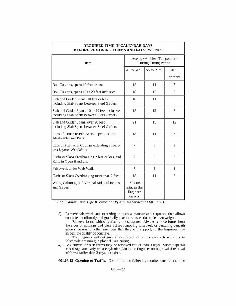
601—27
REQUIRED TIME IN CALENDAR DAYSBEFORE REMOVING FORMS AND FALSEWORK(1)
ItemAverage Ambient Temperature
During Curing Period
41 to 54 °F 55 to 69 °F 70 °F
or more
Box Culverts, spans 10 feet or less 18 11 7
Box Culverts, spans 10 to 20 feet inclusive 18 12 8
Slab and Girder Spans, 10 feet or less,including Slab Spans between Steel Girders
18 11 7
Slab and Girder Spans, 10 to 20 feet inclusive,including Slab Spans between Steel Girders
18 12 8
Slab and Girder Spans, over 20 feet,including Slab Spans between Steel Girders
21 15 12
Caps of Concrete Pile Bents, Open ColumnAbutments, and Piers
18 11 7
Caps of Piers with Copings extending 3 feet orless beyond Web Walls
7 5 3
Curbs or Slabs Overhanging 2 feet or less, andRails in Open Handrails
7 5 3
Falsework under Web Walls 7 5 3
Curbs or Slabs Overhanging more than 2 feet 18 11 7
Walls, Columns, and Vertical Sides of Beamsand Girders
18 hoursmin. as theEngineerdirects
(1)For mixtures using Type IP cement or fly ash, see Subsection 601.03.03
3) Remove falsework and centering in such a manner and sequence that allowsconcrete to uniformly and gradually take the stresses due to its own weight.
Remove forms without defacing the structure. Always remove forms fromthe sides of columns and piers before removing falsework or centering beneathgirders, beams, or other members that they will support, so the Engineer mayinspect the quality of concrete.
The Engineer will not grant any extension of time to complete work due tofalsework remaining in place during curing.
4) Box culvert top slab forms may be removed earlier than 3 days. Submit specialmix design and early release cylinder plan to the Engineer for approval if removalof forms earlier than 3 days is desired.
601.03.15 Opening to Traffic. Conform to the following requirements for the time
601—28
of opening a completed structure to traffic or application of significant loads. TheEngineer will consider construction equipment passing over a structure to be traffic.
1) The Engineer will allow early opening to traffic or application of significant loadsunder the same criteria as early removal for forms and falsework with thefollowing additional requirements:
a) Ensure that results of the compressive strength tests demonstrate a minimumof 100% the required 28 days compressive strength, for the class of concretespecified.
b) When possible, continue to cure concrete for the time specified in thefollowing table even when the specified strength requirements have beenmet.
2) If early release cylinders are not requested or have failed strength requirements,do not open the structure to traffic or subject it to significant loads until theminimum time has elapsed as specified in the Required Time in Calendar DaysBefore Removing Forms and Falsework table in Subsection 601.03.14 and theRequired Time in Calendar Days Before Applying Significant Loads on ConcreteStructures table in this subsection. The curing time will start after placing the lastconcrete in the structure, with the exception of handrails not designed as loadsupporting members. The Engineer will add one day to the following calendardays shown in the table for each day the average ambient air temperature fallsbelow 40 °F.
The Engineer will take air temperature readings at 7:00 AM and 3:00 PMeach day during the curing period and will determine the average temperaturefrom those readings.

601—29
REQUIRED TIME IN CALENDAR DAYSBEFORE APPLYING SIGNIFICANT LOADS ON CONCRETE STRUCTURES
ItemAverage Ambient Temperature
During Curing Period
40 to 54 °F 55 to 69 °F 70 °F
or more
Box Culverts, spans 10 feet or less 21 13 10
Box Culverts, 10 to 20 feet inclusive 22 14 11
Slab and Girder Spans, 10 feet or less,including Slab Spans between Steel Girders
21 13 10
Slab and Girder Spans, 10 to 20 feet inclusive,including Slab Spans Steel Girders
22 14 11
Slab and Girder Spans, over 20 feet,including Slab Spans between Steel Girders
23 18 14
Overhanging Slabs, age before barrier walls areplaced(2)(3)
23 18 14
Caps on Concrete Pile Bents, Open ColumnAbutments, and Piers
1
Concentrated Loads, as produced by steelsuperstructures or precast concrete
18 11 7
Distributed Loads, as produced by poured-in-place concrete deck girder superstructures
3 2 1(2)
Class “D” Piles, Moved or Driven(1) 28 21 21
Class “D” (HES) Piles, Moved or Driven(1) 7 5 3
Class “D” Modified Piles, Moved or Driven(1) 14 10 7
Backfill against Abutments or Retaining Walls 14 10 7(1) See Subsection 604.03.(2) No strength requirements apply.(3) The Engineer will not apply time limits when falsework is designed to support
barrier wall.
601.03.16 Joints.
A) Expansion and Contraction Joints for Structures. Construct expansion jointsto allow absolute freedom of movement. After completing all work, use a finechisel to carefully remove all loose or thin shells or mortar likely to spall undermovement from expansion joints.
Provide and place expansion joints at locations specified in the Plans andStandard Drawings as follows:
1) Friction or Sliding Joints. Friction or sliding joints may be either metal,

601—30
neoprene, rubber, or premolded filler type as specified.2) Open Joints. Place at locations designated and form by insertion and
subsequent removal of a template of timber, metal, or other suitable andapproved material. Use a method of insertion and removal of joint templatesthat avoids the possibility of chipping or breaking the edges and constructthe templates so removal is readily accomplished without injury to the work.Do not extend reinforcement across an open joint unless specified in thePlans. Carefully set structural steel angles, channels, plates, or other shapesused in connection with open joints to conform to the crown and grade of thebridge deck. Construct the joint with a uniform opening and to dimensionsspecified in the Plans.
3) Special Types. Use special types other than those listed when specified inthe Plans or when the Engineer so orders in writing. Furnish special detailsfor such joints.
B) Expansion Joints for Non-Structural Items. Install expansion joints at allbreaks in alignment and at all locations where one concrete construction abutsanother concrete or other type construction. Install expansion joints at each 1,000feet of continuous construction. The Engineer will not require steel reinforcementin expansion joints.
When another concrete item crosses an expansion joint in JPC pavements,construct the expansion joint for the structural or non-structural concrete item oneinch wide and construct all other expansion joints 1/2 inch wide. The Engineerwill not require expansion joints in paved ditches except at locations where thepaved ditch abuts another structure. Cut the one-inch thick expansion jointmaterial to conform to the cross section of the concrete.
C) Contraction Joints for Non-Structural Concrete Items. Either form 1/8-inchwide contraction joints for non-structural concrete items or construct themaccording to requirements of this subsection at intervals not to exceed 30 feet,except when items are constructed on or adjacent to a rigid pavement or shoulder.For these exceptions, make the joint spacing coincide with that of the pavementor shoulder. Space contraction joints for sidewalks as specified in Section 505.The Engineer will not require the sealing of contraction joints in non-structuralitems.
The Engineer will not require contraction joints for paved ditches. Constructsawed contraction joints to a minimum depth of 2 inches, except that theEngineer will allow one inch of depth for header curbs and integral curbs.
601.03.17 Curing Concrete. Cure reinforced concrete bridge slabs according toSubsection 609.03. Wet cure all surfaces that are to receive a masonry coating finish,unless using combination material. When using combination material, cure as specified inB) below. Either wet cure all other concrete, except pipe culvert headwalls, as specified inA) below or cure it by application of membrane forming compound as specified in B)below. The Engineer will not require curing for cast-in-place pipe culvert headwalls.
At any time the Engineer determines concrete on the project is not being properlycured, the Engineer may suspend all or any concreting operations on the project.
At any time during the curing period when the atmospheric temperature is 45 °F orless, protect the concrete to satisfy the temperature requirements according to Subsection601.03.09 D).
A) Wet Curing. Cure concrete for a period of at least 7 calendar days, beginningimmediately after placement and finishing, by frequently applying water to allsurfaces to keep them continuously damp during the full 7-calendar day curingperiod or until the required strength is attained. Protect exposed concretesurfaces from drying by application of a double thickness of wet burlap or similarapproved material and keep the burlap or other approved material continuouslywet for a period of 7 or more calendar days. Soak new burlap in water for at least

601—31
12 hours before the first use.When the structure or any portion thereof is enclosed and artificial heat is
provided for protection, the Engineer will not waive the moist curingrequirement. When using steamlines for heating, leave the pipe loose sosufficient steam escapes into the housing to maintain a moist atmosphere at alltimes. When using stoves or salamanders, maintain vessels containing water oneach stove or salamander to maintain a moist atmosphere at all times. TheDepartment will allow the curing of flat horizontal surfaces with curing blankets.
B) Membrane Curing. Do not dilute or alter the membrane forming curingcompound. Thoroughly agitate the compound immediately before using it.When the compound is too viscous to apply, warm it in a water bath toapproximately 100 °F before applying.
Uniformly apply the compound to a surface by use of an approved pressuresprayer. The Department will allow the placement of curing compound in oneapplication. When placing in one application, achieve uniform and satisfactorycoverage. If the Engineer directs that 2 applications are required because oneapplication is not satisfactory, then make each application at the rate of onegallon per 300 or less square feet. Start the first application as soon as practicalafter the final finish and as the Engineer directs, and start the second applicationafter finishing the first application. Use a total actual application rate of at leastone gallon per 150 square feet or less actual coverage.
Do not apply curing compound to construction joints, reinforcing steel, orsurfaces to receive a masonry coating, except:
1) The Department will allow the use of materials conforming to the waterretention requirements of AASHTO M 148 for liquid membrane formingcuring compound, and also conforming to Section 828 for masonry coating,on areas designated to receive masonry coating.
2) When using combination materials, follow wet curing procedures untilcompleting all patching or other surface corrections and applying thecompound. Keep the surface covered with wet burlap or other approvedmaterial and alternately expose small sections for surface corrections, toavoid drying. Conform to surface preparation requirements for masonrycoating in all respects.
When inadvertently applying curing compound to surfaces upon whichthe compound is not allowed for use, remove it by sandblasting.
Protect the curing compound and maintain it in an acceptable conditionfor a period of at least 7 calendar days. Moisten and respray curingcompound on surfaces on which the curing compound is damaged before theend of the 7-calendar day curing period. Cover surfaces upon which curingcompound has been applied and that will be used as work surfaces orotherwise subject to damage to the curing compound with planks, boards, orother protective material to protect the curing compound from damage.
C) Curing Blankets. Only use curing blankets for curing bridge deck slabs andother flat horizontal surfaces.
Keep the concrete continuously damp for the period of time specified for theitem being constructed, beginning immediately after placing and finishing. Assoon as possible, without damaging the concrete surface, moisten the concrete byapplying water, and immediately cover the surface with the curing blankets.
Place the blankets so that adjoining blankets overlap at least 18 inches.Weight all laps and outside edges to prevent displacement of the blankets beforecompleting curing. Ensure intimate contact between the blankets and theconcrete surface.
If the blankets are disturbed before the curing time expires, immediatelyreplace them. Apply water at any time drying of the concrete is evident.
Immediately repair torn places in the blankets by cementing an additional
601—32
thickness of the same material over the torn area. At the end of each curingperiod, inspect the blankets; repair all tears or holes before reusing the blankets.
601.03.18 Surface Finish. Apply the following surface finishes to various parts ofconcrete structures:
1) Ordinary Surface Finish,2) Masonry Coating Finish, or3) Floated Surface Finish.
Apply ordinary surface finish to all concrete surfaces not required to have masonrycoating finish or a floated surface finish. Consider ordinary surface finish as a final finishon all surfaces not required to have masonry coating.
Ensure that exposed finished concrete surfaces do not vary more than 1/4 inch in 10feet as measured from a straightedge.
A) Ordinary Surface Finish. Immediately following removal of forms, remove allfins and irregular projections from all surfaces except those not to be exposed inthe completed work. On all surfaces, that have cavities and depressions resultingfrom removal of form ties, and all other holes, honeycomb spots, broken cornersor edges, and other defects, thoroughly clean the defects, saturate them withwater, and carefully point them. Use a mortar of the same cement and fineaggregates mixed in the same proportions as used in the class of concrete beingfinished. Do not use a mortar that is more than 30 minutes old, and cure themortar patches as specified for the structures. After the mortar has thoroughlyhardened, finish it with a carborundum brick to obtain a uniform and smoothsurface that is the same color and texture as in the surrounding concrete. Whenrequired, chip out honeycomb areas before pointing. Carefully tool all open andfilled contraction and expansion joints in the completed work and keep them freeof all mortar and concrete. Expose the joint filler for its full length with cleantrue edges.
Obtain smooth and even surfaces of uniform color and texture withoutunsightly bulges, patched areas, depressions, and other imperfections.
The Engineer will consider individual surfaces satisfactory and incompliance with requirements for ordinary surface finish when the surfaces havebeen formed and finished as specified and the Engineer has approved theresultant surface as to uniformity, color, texture, and smoothness.
The Engineer will consider each face of a column, wing, girder, or parapetseparately in determining if the finish is satisfactory.
Protect all exposed surfaces from subsequent construction operations andfrom drip and disfigurement. Clean and finish any surface disfigured as a resultof construction or other operations as the Engineer may require to give asatisfactory surface finish.
B) Masonry Coating Finish. After the Engineer has inspected and accepted theconcrete surfaces of bridges and median barriers as having a satisfactory ordinarysurface finish, clean the concrete surfaces specified hereinafter of all dust, foreignmatter, and form oil, and apply a Department approved masonry coating finish.Coat the following surfaces, including all beveled edges:
1) Bridge End Bents, Abutments, Retaining Walls, and Headwalls for box orlong span underpasses - every exposed surface including wingwalls, above apoint 6 inches below ground or fill line.
2) Bridge Pier Caps - the tops (including exposed surfaces of pads, pedestals,and keys), sides and ends. Do not apply the coating to bearing areas.
3) Bridge Superstructure - the tops, inside and outside faces, and ends of allbarrier walls, parapets, curbs, and plinths that will be exposed. Do notapply the coating to the riding surface of the bridge deck.

601—33
4) Median Barriers - all exposed surfaces of concrete median barriers andconcrete terminal sections appurtenant to the barriers.
5) Exposed Surfaces of Substructure and the Superstructure of Highway,Railway, and Pedestrian Bridges Over a Highway - all surfaces identified in1), 2), and 3) above and the underneath surfaces of slab overhangs that areoutside of exterior girders and the exterior side and bottom of exteriorbeams, girders and box beams and all exposed surfaces of piers, abutmentsand walls that are within 200 feet of a public road or street. Extend themasonry coating from a point 6 inches below ground line to the top of theexposed surface.
Thoroughly clean all surfaces to receive a masonry coating and keep themfree of oil, form oil, grease, dust, dirt, mud, curing compound, release agents,loose patching mortar, or any other substance that may prevent bonding. Beforeapplying the masonry coating material, fill all air holes flush with the surfacewith the masonry coating material or an approved mortar to provide a uniformsurface.
Check all surfaces to receive a masonry coating for the presence of dust bywiping a dark cloth across the surface of the concrete. If a white powder can beseen on the dark cloth, clean the concrete by wire brushing, grinding, or waterblasting and then allow it to thoroughly dry before applying the masonry coating.The Engineer will recheck the surface for the presence of dust after cleaning.
Check all surfaces to receive a masonry coating for the presence of oilyconditions by sprinkling or fogging water on the surface of the concrete. If thewater stands in droplets without spreading out immediately, this indicates thesurface is contaminated with an oily substance, and the Engineer will requirecleaning using a detergent and water followed by thorough rinsing with water.The Engineer will recheck the surface for the presence of oily conditions aftercleaning.
Thoroughly dry all surfaces to receive a masonry coating before applying thecoating, unless the coating manufacturer specifically recommends the surface tobe wet. The Department’s List of Approved Materials contains eachmanufacturer’s recommendation. The Engineer will not consider surfaces to bedry unless an absorbent paper pressed tightly against the surface does not showany trace of moisture.
Suspend coating application any time the ambient temperature or thetemperature of the concrete does not comply with the coating manufacturer’srecommendations.
Prior to application of the materials, furnish the Engineer with copies of thecoating material manufacturer’s brochures or booklets. Apply masonry coatingmaterials in strict conformity with the manufacturer’s written instructions andapply the material at a uniform rate of at least 50 ± 10 square feet per gallon.
Satisfactorily repair or remove any portions of the coating that are not clean,uniform in color, texture, thickness, tightly bonded, or that are damaged beforefinal acceptance of the project and replace them with an acceptable finish andcoating.
Provide a neat uniform appearance, and prevent the coating from beingdripped, sprayed, or otherwise deposited upon concrete or steel surfaces notdesignated to receive the coating. Remove any objectionable deposits or materialand repair the surfaces to the Engineer’s satisfaction.
C) Floated Surface Finish. Finish horizontal surfaces not subject to wear, andthose that do not receive the Masonry Coating Finish, such as back walls, andheadwalls, by placing an excess of materials in the form and removing or strikingoff such excess with a wooden template, forcing coarse aggregate below themortar surface. Do not use mortar topping for surfaces falling under thisclassification. After striking-off the concrete as described, thoroughly work thesurface and float it by hand with a wooden float leaving a fine grained, smooth-
601—34
sanded surface.Finish concrete bridge floors as specified in Section 609.Finish sidewalks on structures as specified in Section 505.
601.03.19 Construction Date and Identification. On all concrete bridges and boxculverts, stencil the year the Contract was executed and the structure drawing number onthe concrete at the locations designated. Make the figures on the stencil according todetails specified in the Plans. For bridges having a clear span of 20 feet or more, stencilthe year the Contract was executed and load capacity of the structure on the outside face ofthe plinth or barrier wall as shown on the Standard Drawing or as directed. On all boxculverts, place stenciled figures giving the year in which the Contract is executed on theinlet end of the culvert on the outside face and center of the parapet or headwall. Do notuse permanent plates or markers of any kind, other than those shown, on any structure. Onall bridges, imprint the name(s) of the prime contractor, and the subcontractor whenapplicable, in the concrete at the location shown or designated. Furnish stencils, allequipment, tools, labor, materials, and other incidentals necessary.
601.04 MEASUREMENT.
601.04.01 Concrete. The Department will measure the quantity in cubic yardsaccording to the dimensions specified in the Plans. The Department will not measure thevolume of concrete displaced by pile heads (except when using concrete piles) for paymentand will consider it incidental to this item of work. The Department will measure thevolume of concrete displaced by concrete pile heads in cubic yards. The Department willnot measure forming, including permanent steel forms, for payment and will consider itincidental to this item of work. The Department will measure the average core strength inpsi by testing cores. The Department will not measure the average core strength as aseparate pay unit, but will use it to calculate an adjusted Contract unit price for Concrete,Class M1 or M2.
601.04.02 Steel Reinforcement. The Department will measure the quantityaccording to Subsection 602.04.
601.04.03 Masonry Coating. The Department will measure the quantity in squareyards.
601.04.04 Mass Concrete. The Department will measure the quantity in cubic yardsactually placed.
601.05 PAYMENT. The Department will make payment for the completed andaccepted quantities under the following:
Code Pay Item Pay Unit8100, 8102-8106, 2555 Concrete, Class(1) Cubic Yard8150 Steel Reinforcement See Subsection 602.052998 Masonry Coating Square Yard10040 Mass Concrete(2) Cubic Yard
(1) The Department will adjust the Contract unit price for Concrete, Class M1and Concrete, Class M2 by the Schedule for Adjusted Payment for StrengthDeficiency. The adjusted quantity is equal to the plan quantity of Concrete,Class M1 or Concrete, Class M2 multiplied by the Contract unit price forthe Concrete, Class M1 or Concrete, Class M2 and the Price Adjustment.The Department will not make additional payment for average corestrengths in excess of the specified strength.
(2) The Department will pay for Mass Concrete at a unit price of 2 times the
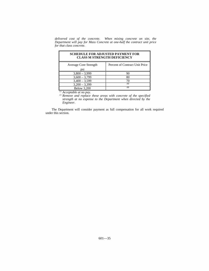
601—35
delivered cost of the concrete. When mixing concrete on site, theDepartment will pay for Mass Concrete at one-half the contract unit pricefor that class concrete.
(1) Acceptable at no pay.(2) Remove and replace these areas with concrete of the specified
strength at no expense to the Department when directed by theEngineer.
The Department will consider payment as full compensation for all work requiredunder this section.
SCHEDULE FOR ADJUSTED PAYMENT FORCLASS M STRENGTH DEFICIENCY
Average Core Strength Percent of Contract Unit Pricepsi
3,800 – 3,999 903,600 – 3,799 803,400 – 3,599 703,200 – 3,399 (1)
Below 3,200 (2)
602—1
SECTION 602 STEEL REINFORCEMENT
602.01 DESCRIPTION. Furnish and place steel for reinforcement of concrete.Furnish bars, spirals, welded wire fabric, bar mat, or other specified reinforcement, of thequality, type, size, and quantity designated by the Contract.
602.02 MATERIALS.
602.02.01 Steel Reinforcement. Conform to Section 811.
602.02.02 Epoxy Coating Material. Conform to Section 811.
602.02.03 Welded Steel Wire Fabric (WWF). Conform to Section 811.
602.03 CONSTRUCTION.
602.03.01 Protection of Material. Handle and store steel reinforcement to preventbending, excessive rusting, or contamination with objectionable substances.
602.03.02 Straightening. Before placing in the work, straighten reinforcement bentduring shipment or handling without injuring the steel. Do not heat the steel, or use steelwith sharp kinks.
602.03.03 Bending. Bend reinforcement cold to the dimensions and shapes specifiedin the Plans and to within tolerances designated in the CRSI Manual of Standard Practice.In bending, do not injure the steel. Bend bars in the shop before shipment, not in the field.
602.03.04 Placing and Fastening. Accurately place all steel reinforcement asshown, and firmly hold in position while placing and during hardening of concrete. Holdin position to within a tolerance of ± 1/2 inch, and place to within a tolerance of ± 1/4 inchof specified clearance from the face of concrete, except for bridge deck reinforcement steel.Place steel reinforcement for bridge slabs to within the tolerances specified in Subsection609.03.03. Dimensions shown from the face of concrete to bars are clear distances. Barspacings are from center to center of bars. Tie bars at all intersections, except wherespacing is less than one foot in both directions, then tie alternate intersections. Alwayspass vertical stirrups around the main tension members and securely attach them to themembers.
Use Engineer approved supports to maintain distances from forms. Use precastblocks composed of mortar or Engineer approved metal chairs as supports for holdingreinforcement from contact with the forms. Ensure that the tips of metal chair supports incontact with the surface of the concrete are plastic coated steel. When using plastic coatedsteel supports, provide a minimum of 1/8 inch thickness of the plastic material between themetal tips and the exposed surface of the concrete. The Engineer will accept metalsupports as specified for epoxy coated bars. Securely tie down the steel placed inreinforced concrete slabs to prevent any possibility of steel rising above the specifiedelevation during placing, vibrating, and finishing the concrete as required by Subsection609.03. Ensure that metal supports have a shape that will be easily enveloped by theconcrete.
Separate the top and bottom mats of bars with precast mortar blocks or by otherequally suitable devices. Do not use pebbles, pieces of broken stone or brick, metal pipe,and wooden blocks as separators. Securely place reinforcement in any member, and thenobtain the Engineer’s approval before placing concrete. The Engineer may reject concreteplaced in violation of this provision.
When using grout to install steel bars into existing concrete, conform to Section 511.
602—2
602.03.05 Special Requirements for the Installation of Epoxy Coated Bars.Either coat all tie wires, clips, chair and bar supports, and other metallic materials used forthe installation of the epoxy coated reinforcing bars with fusion bonded epoxy resin or withan approved vinyl type material, or make them of an approved non-metallic material.
Use an epoxy material that provides a uniform continuous coating having a filmthickness of 12 ± 7 mils. Use vinyl-type material that is pliable and provides a uniformcontinuous coating having a thickness of 30 ± 10 mils. Test installation devices coatedwith either material according to KM 64-106.
Allow the Engineer to check the installation devices for flaking, chipping, or any otherdefects during the pre-pour inspection of the epoxy coated reinforcing bars, and repair orreplace the devices as the Engineer deems necessary.
Coat tie wires with a flexible plastic or vinyl material to a thickness of 12 ± 7 mils.The Engineer will test the coating according to KM 64-106.
Provide all systems for handling coated bars with padded contact areas for the barswhenever possible. Pad all bundling bands, and lift all bundles with a strong back,multiple supports, or a platform bridge so as to prevent bar-to-bar abrasion from sags inthe bar bundle. Use nylon slings for direct epoxy bar contact. Use loading and unloadingprocedures and equipment that does not damage the coating.
Unload and store the epoxy coated steel bars on the project site in a manner to avoiddamage or contamination. Avoid extended outdoor storage of coated bars of over 2months. If expecting the outdoor storage to exceed 2 months, cover the bars for protectionagainst the elements and to prevent condensation from forming on the bars. Install thebars in the bridge deck according to applicable requirements of Section 609, except asprovided in this section and as the Engineer deems necessary in order to protect andpreserve the epoxy coating.
Repair all cuts, nicks, and abrasions that exceed 0.25 percent of the surface area andthe bar end with the epoxy repair material supplied by the powdered epoxy resinmanufacturer. If the areas damaged during transportation, handling, and placing exceed 2percent per foot of the coated area, remove and replace them with acceptable bars. Also,repair any damaged metallic accessories with a suitable material.
Make every reasonable effort to repair all damaged areas of the reinforcing steel andaccessories before any rusting occurs. If infrequent and small damaged areas do rust,thoroughly remove the rust by sandblasting or other Engineer approved methods beforerepairing the areas. Ensure that the coated bars, when incorporated into the work, arereasonably free from dirt, paint, oil, grease, or other foreign substance, and, when deemednecessary, clean the bars to the satisfaction of the Engineer.
Place concrete in the deck using methods and equipment that will not damage thecoated materials.
Since the epoxy coating is flammable, do not expose the coated bars to any fire orflame. Do not cut coated bars by burning.
602.03.06 Splicing. Do not splice any reinforcement that is not of the type and at thelocations specified in the Plans without the Engineer’s written permission. TheDepartment will allow the use of lapped splices, welded splices, mechanical couplers, orother positive connection splices specified in the Plans or designated by Engineer. Do notweld rail steel bar reinforcement used for bridges, cast-in-place culverts, and cast-in-placewalls.
Make all splices added in the field and not specified in the Plans as far from the pointof maximum tensile stress in the member as practical, and stagger splice points 3 feet ormore in adjacent bars, when possible. Do not use any splices which reduce the cleardistance between the splice and the closest bar to less than the minimum clear distancerequired by the design specifications. Do not use mechanical couplers having a diameterof greater than 125 percent of the nominal diameter of the reinforcing bar in the top bars inbeams, slabs, or girders in which the concrete under the top bars is 12 inches or more indepth.
Make all splices with clean, sound materials properly affixed to the members beingspliced and free of any substances that would weaken or contaminate the splice or concrete

602—3
surrounding the splice.Provide lapped splices that have a length no less than that specified in the Plans.
When using lapped splices in areas not specified in the Plans, obtain the Engineer’sapproval. Splice bars by rigidly clamping or to otherwise wire together in a manner theEngineer approves. Make splices for spirals, where necessary, with a minimum lap of 1.5turns of spiral.
When welding splices, conform to the AWS Reinforcing Steel Welding Code. Butttogether and weld bars to develop, in tension, at least 125 percent of the specified yieldstrength of the bars. Do not use welded splices unless specified in the Plans or as theEngineer approves.
Use mechanical couplers primarily for bars required for compression only. Use onlymechanical couplers or bars designed to carry critical tension or compression that areequivalent in strength to approved welded splices (125 percent of the specified bar yieldstrength).
When the Engineer allows welded splices or mechanical couplers, prepare 2 testspecimens of the spliced reinforcement for submittal to the Division of Materials fortesting before incorporating the splices into the work, and submit one additional testspecimen for each 100 splices made. Ensure that only personnel who are qualified inconformance with the AWS Reinforcing Steel Welding Code make the welded splices.
602.03.07 Welded Steel Wire Fabric (WWF). Overlap sheets of WWF by 40 ormore times the nominal diameter of the longitudinal wires to maintain a uniform strength,and securely fasten the sheets at the ends and edges.
602.04 MEASUREMENT.
602.04.01 Steel Reinforcement. The Department will measure the quantity,including bars used to replace test specimens, by the pound in the final work based on thetheoretical number of pounds. The Department will not measure clips, wire, chairs, orother material used for fastening reinforcement in place for payment and will considerthem incidental to this item of work. The Department will not measure welded splicing forpayment and will consider it incidental to this item of work.
The Department will base quantities of materials furnished and placed on thecalculated weights of the reinforcing steel actually placed. The Department will calculatethe weights based upon the following table:
ASTM STANDARD REINFORCING BARS
Bar Size Nominal Mass Nominal Dimensions - Round SectionsEnglish
and (metric)poundsper foot
Diameterinches
Cross SectionArea, sq. inches
Perimeterinches
#3 (10) 0.376 0.375 0.11 1.178#4 (13) 0.668 0.500 0.20 1.571#5 (16) 1.043 0.625 0.31 1.963#6 (19) 1.502 0.750 0.44 2.356#7 (22) 2.044 0.875 0.60 2.749#8 (25) 2.670 1.000 0.79 3.142#9 (29) 3.400 1.128 1.00 3.544#10 (32) 4.303 1.270 1.27 3.990#11 (36) 5.313 1.410 1.56 4.430#14 (43) 7.650 1.693 2.25 5.320#18 (57) 13.600 2.257 4.00 7.090
602—4
602.04.02 Steel Reinforcement, Epoxy Coated. The Department will measure thequantity according to Subsection 602.04.01. The Department will not measure the epoxycoating or its application for payment and will consider it incidental to this item of work.
602.04.03 Mechanical Couplers. The Department will measure the quantity byeach individual unit.
602.05 PAYMENT. The Department will make payment for the completed andaccepted quantities under the following:
Code Pay Item Pay Unit8150 Steel Reinforcement Pound8151 Steel Reinforcement, Epoxy Coated Pound73003, 7113 73023, 73033 Mechanical Reinforced Couplers, Size Each
The Department will consider payment as full compensation for all work requiredunder this section.
603—1
SECTION 603 FOUNDATION PREPARATION ANDBACKFILL
603.01 DESCRIPTION. Excavate and backfill or dispose of all materials required forthe construction of bridges, box culverts, and other structures for which excavation is nototherwise provided.
603.02 MATERIALS AND EQUIPMENT. Use fabric wrapped backfill drainsconforming to Section 845.
603.03 CONSTRUCTION. Remove and dispose of all materials excavated for theconstruction of the foundations for all structures, including the removal of existingstructures. Place backfill to the original ground level and perform final cleaning up.
603.03.01 Classification. Perform structure excavation necessary for all bridgefoundations and culverts, except pipe culverts, as Structure Excavation Solid Rock orStructure Excavation Common. Perform structure excavation necessary in the constructionof cribwalls and retaining walls as Structure Excavation Unclassified.
A. Structure Excavation Solid Rock. The Department considers all of thefollowing Structure Excavation Solid Rock:
1) All rock in solid beds, detached masses, or ledge formations which cannotbe removed without blasting or quarrying. Hoerams and jackhammers maybe required for solid rock removal.
2) Detached rocks or boulders having a volume of 0.5 cubic yards or moreeach.
3) Shale, slate, or coal which cannot be removed without blasting or quarrying.4) Rock layers interspersed with strata of earth, or all conglomerate boulder
formations, when rock strata or boulders constitute 60 percent or more of thevolume to be removed.
B. Structure Excavation Common. The Department considers StructureExcavation Common as all material not classified as Solid Rock StructureExcavation.
C. Structure Excavation Unclassified. The Department considers StructureExcavation Unclassified as all excavation regardless of the materialsencountered.
603.03.02 Channel Preservation. When any excavation or dredging is done at thesite of the structure, do not excavate outside of caissons, cofferdams, steel piling, orsheeting, and do not disturb the natural stream bed adjacent to the structure without theEngineer’s written permission.
603.03.03 Footing Excavation. Notify the Engineer at least 48 hours in advance ofbeginning structure excavation.
Excavate the foundation pits to allow placing of the full width and length of footingsspecified in the Plans with full horizontal beds. Do not use rounded or undercut cornersand edges of footings. Ensure that all rock and other hard foundation material is free fromall loose material, cleaned, and cut to a firm surface, either level, stepped, or roughened, asdirected. Clean all seams and fill with concrete, mortar, crushed stone, or sand. Whenmasonry is to rest on an excavated surface other than durable rock or durable shale (SDIequal to or greater than 95 according to KM 64-513), do not disturb the bottom of theexcavation, and do not make the final removal of the foundation material to grade until justbefore the masonry is to be placed. When unsuitable foundation material is encountered,excavate and replace with acceptable material as the Engineer directs. Maintain the
603—2
excavation free of standing water, insofar as is practical.When the Plans require the foundation for a bridge or culvert to be solid rock or shale,
drill into the foundation material to confirm its suitability. Drill according to the Divisionof Construction’s Guidance Manual.
603.03.04 Backfilling. Use only approved materials that will provide a dense well-compacted backfill. Ensure that the backfill material is free of frozen lumps, vegetation,debris, and rock fragments larger than 4 inches in any dimension. Before starting backfill,clear the excavated pits of all form material and rubbish, and, when practical dewater thepits.
Place and compact backfill material in uniform horizontal lifts not exceeding one footfor stone and 6 inches for soil and rock/soil combination material. For backfill that will bebeneath, or within a proposed embankment, backfill according to Subsection 206.03.03.
When backfilling piers constructed in a stream bed or flood plain, the Departmentwill allow material removed from the excavation as backfill material provided no largerock or broken concrete fragments are placed in contact with the structure, and provided nologs, stumps or rubbish are used. Backfill below normal low water elevation will notrequire compaction.
Shape the backfilled areas lying outside the limits of roadway embankment to auniform finish.
As a precaution against introducing unbalanced stresses in masonry walls or columns,place and compact the backfill to the same elevation on both sides of culverts, wingwalls,piers, and abutments before proceeding to the next layer.
For structures over which rock fills will be constructed, first cover the structures to aminimum depth of 2 feet with materials placed and compacted as required for backfill.
Obtain the Engineer’s permission before backfilling against any concrete masonrystructure.
603.03.05 Drainage. At locations where depth to weep hole flowline is 30 feet orless, drain backfill by installing a fabric-wrapped drain.
Center a fabric-wrapped drain over the inlet end of each weep hole with a wide sideagainst the concrete, and glue the drain in place. Use a glue recommended by the drainmanufacturer. Ensure that glue is not placed over the portion of the drain covering theweep hole. Place drains vertically at each weep hole.
Extend the drain from top of footing or from 6 inches below the inlet end of weepholes to 6 inches below subgrade elevation or, in the case of box culverts, to the top of thetop slab. Avoid damaging or compressing the drain during backfilling.
When splices are required, provide a 6-inch lap of fabric to be glued to the adjacentpiece so the spliced drain is completely covered by fabric.
Provide flaps or separate pieces of fabric to cover the top and bottom of the drain, andoverlap the fabric on all sides of the drain at least 6 inches.
At the weep hole, if necessary, puncture the plastic core to provide free drainage fromthe drain to the weep hole. If puncturing of the core is necessary do not puncture thegeotextile fabric on the outside face of the drain. Place a piece of plastic, at least 8 inchesby 8 inches by 3/16 inches on the outside face of the drain over the weep hole, asreinforcement.
When depth to weep hole flow line is greater than 30 feet, cover the inlet ends of weepholes with at least 2 cubic feet of No. 57 coarse aggregate. Place the aggregate to allowfree drainage but at the same time prevent the fill from washing. From approximately 6inches below the bottom of the inlet ends of the weep holes, place a column of cleancrushed stone or gravel, at least one square foot, up against the back of the wall to theupper limits of the backfill. At the time of placing the remainder of embankment adjacentto the structure, continue placing the column of stone up to subgrade elevation, or, in thecase of box culverts, to the top of the top slab.
603.03.06 Cofferdams. For foundation construction, drive sheet piles forcofferdams to an elevation well below the bottom of the footings. Brace walls to ensure
603—3
against collapse. Provide interior dimensions that allow sufficient clearance for theconstruction of forms and the inspection of their exteriors, and to permit pumping outsidethe forms. Right, reset, or enlarge cofferdams that are tilted or moved laterally during theprocess of sinking to provide the necessary clearance. Construct cofferdams sufficientlywatertight to prevent water from coming in contact with fresh concrete. Do not allowbracing to extend into the substructure masonry unless the Engineer permits in writing.Submit drawings prepared by a Registered Professional Engineer showing the design andconstruction methods of proposed cofferdams. Include in the drawings all necessarydetails and design calculations. The type and clearance of cofferdams, details that affectthe character of the finished work and the safety of the installation are subject toDepartment approval. The Department will review design details of cofferdams, bracing,shoring, or other work.
Remove all cofferdams, including all sheeting and bracing, after completion of thesubstructure without disturbing or causing damage to the finished masonry.
603.03.07 Foundation Seals. When conditions are encountered which, in thejudgement of the Engineer, render it impracticable to remove water from the cofferdambefore placing masonry, the Engineer may require construction of a concrete foundationseal according to Subsection 601.03.09 B).
Do not dewater cofferdam until the concrete seal has set sufficiently to withstand thehydrostatic pressure and in no case less than 72 hours after placement.
The Engineer may require longer than 72 hours.
603.04 MEASUREMENT. The Department will not measure the removal of existingstructures, or portions thereof, in structure excavation when listed in the Contract as a biditem.
The Department will measure removing masonry necessary in the building ofextensions to or the rebuilding of an existing structure according to Section 203.
The Department will consider removal of existing pipe incidental to structureexcavation and will deduct the interior volume of the pipe from the structure excavationquantity.
When the Plans require the foundation to be solid rock or shale, drilling to confirmsuitability is incidental to the structure excavation.
603.04.01 All Structures. When it is necessary to backfill in excess of the materialexcavated, the Department will measure the quantity of the additional material necessaryfor such backfill in cubic yards in its original position under Borrow Excavation orRoadway Excavation, unless it is paid for as Extra Work.
The Department will not measure dewatering excavated pits and placing andcompacting backfill for payment and will consider them incidental to the structureexcavation bid items.
When not listed as a bid item, the Department will not measure furnishing andplacing fabric wrapped drains or coarse aggregate at weep holes for payment and willconsider them incidental to the structure excavation bid items.
When it is necessary to construct any footing more than 5 feet below the elevationspecified in the Plans for structures, except pipe culverts, sewers, and underdrains, theDepartment will pay for all excavation below plan elevation as Extra Work.
The Department will not measure excavation or backfill in excess of the limitsdescribed in this section for payment.
603.04.02 Bridges, Culverts, and Retaining Walls. The Department will measurethe quantity of all excavation in its original position as that actually excavated within thelimits bounded by vertical planes 18 inches outside the footings and parallel thereto exceptas follows. The Department will measure between the original ground surface and thebottom of the excavated pit, except in cuts where the finished cross section will govern,and except when structures are removed, the bottom of the excavation for removal shallgovern. The Department will not include in the quantity the volume of the waterway of
603—4
existing culverts and bridges, the volume of materials removed as Remove ExistingStructure, nor materials removed as incidental. The Department will not measure structureexcavation for pipe culverts and pipe culvert headwalls, sewer pipe, or combination sewerand storm pipe.
Where tie beams, struts, web walls, overhangs, or similar construction are required onthe substructure above the bottom of the footings and extend beyond the area bounded byvertical planes 18 inches outside the footings, the Department will measure the excavation,except that the Department will measure the area bounded by vertical planes 18 inchesoutside the footings and 18 inches outside the neat lines of the tie beams, struts, web walls,and other similar construction. The Department will measure between the original groundsurface and a plane 18 inches below the bottom of the tie beams, struts, web walls, andother similar construction.
The Department will not measure excavation necessary to construct concreteencasement for an individual steel pile for payment and will consider it incidental to thepile. The Department will not measure Structure Excavation in the construction of timberbents or backing planks, or for excavation incidental to splicing piling for payment.
603.04.03 Foundation Preparation. When listed as a bid item, the Department willmeasure all work performed as part of Foundation Preparation as a lump sum for eachstructure. The Department will not measure cofferdams, shoring, dewatering, commonexcavation, or backfill for payment, and will consider them incidental to this bid item. TheDepartment will measure Structure Excavation Solid Rock and removal of unsuitablefoundation material and refill separately for payment.
603.04.04 Structure Excavation Common. When Foundation Preparation is notlisted as a bid item, the Department will measure the quantity, in cubic yards. TheDepartment will not measure any material removed or excavated before the Engineer takesmeasurements.
603.04.05 Structure Excavation Solid Rock. The Department will measure thequantity in cubic yards. The Department will not measure any material removed orexcavated before the Engineer takes measurements.
603.04.06 Structure Excavation Unclassified. The Department will measure thequantity in cubic yards. The Department will not measure any material removed orexcavated before the Engineer takes measurements.
603.04.07 Foundation Undercut. When Foundation Preparation is not a bid itemand the Engineer directs that unsuitable foundation material is be excavated and replaced,the Department will measure the quantity of excavation as Structure Excavation Common,Structure Excavation Solid Rock, or Structure Excavation Unclassified in cubic yards, asapplicable, which will be complete compensation for all excavation, disposal, backfill, andall other incidentals necessary to prepare a suitable foundation.
When Foundation Preparation is a bid item, the Department will pay for FoundationUndercut as Extra Work.
603.04.08 Cofferdams. The Department will not measure the quantity unless it islisted as a separate bid item and will consider it incidental to the bid item StructureExcavation or Foundation Preparation.
603.04.09 Foundation Seals. The Department will not measure the quantity unlessit is listed as a separate bid item or the work is directed by the Engineer.
603.05 PAYMENT. The Department will make payment for the completed andaccepted quantities under the following:

603—5
Code Pay Item Pay Unit8002 Structure Excavation Solid Rock Cubic Yard8001 Structure Excavation Common Cubic Yard2203 Structure Excavation Unclassified Cubic Yard2210 Borrow Excavation See Section 205.052200 Roadway Excavation See Section 204.058003 Foundation Preparation Lump Sum
The Department will consider payment as full compensation for all work requiredunder this section.

604—1
SECTION 604 BEARING PILES
604.01 DESCRIPTION. Furnish and drive prestressed concrete, precast concrete, cast-in-place concrete, or HP shape structural steel bearing piles.
604.02 MATERIALS AND EQUIPMENT.
604.02.01 Concrete. Conform to Subsection 601.02 and 601.03.
604.02.02 Structural Steel. Conform to Section 812.
604.02.03 Welded Steel Pipe Piles (Cast-In-Place Pile Shells). Conform to ASTMA 252, Grade 3.
604.02.04 Miscellaneous Metals. Conform to Section 813.
604.02.05 Polypropylene Sleeves. Conform to the manufacturer’srecommendations.
604.02.06 Pile Points. Conform to AASHTO M 103, Grade 65/35 or ASTM A 148.Furnish pile points from a supplier on the Department’s List of Approved Materials.
604.02.07 Equipment for Driving.
A) Hammers. Provide hammers for driving precast or prestressed concrete pilesthat develop a minimum energy per blow at each full stroke of the piston of morethan one foot-pound per each pound weight of pile being driven. Use 150pounds per cubic foot as the weight of concrete in the pile being driven. Use ahammer that develops a total energy of 12,000 or more foot-pounds per blow.
Provide hammers for driving steel piles or steel shells for cast-in-place pilesthat develop a minimum energy of 5,000 foot-pound for each ton of steel in thepile or shell being driven and in no case develop less than 10,000 foot-pounds oftotal energy.
Use diesel powered pile hammers with a ram weighing at least 2,000pounds to drive steel piles, concrete piles, and steel shells for cast-in-place piles.For hammers that do not restrict the rebound of the ram use a ram 2,000 poundsor more.
If hammers with an enclosed ram are used, they will have a rated equivalentenergy of no less than 250 foot-pounds per blow per ton of the required bearing.For driving concrete piles, use hammers that have a rated equivalent energy of15,000 foot-pounds or more per blow. Equip hammers of this type with a gageand charts that will evaluate the equivalent energy actually produced under anydriving conditions.
When the Engineer determines the size of the hammer to be unsatisfactory,correct or replace it to produce satisfactory results. Provide the Engineer with themanufacturer’s specifications regarding hammers on request.
B) Leads. Use pile driver leads that allow freedom of movement to the hammer andensure proper distribution of hammer blows on the head of piles. Hold leads inposition with guys, stiff braces, templates, or other Engineer approved means forsupporting the pile during driving.
C) Followers. Avoid driving piles with followers if possible. Use followers onlywith the Engineer’s written permission or when driving piles through water. Ifusing followers, drive one long pile from every group of 10 without a follower,and use this pile to determine the average bearing power of the group.
D) Water Jets. The Department will allow the use of water jets alone or incombination with a hammer. Provide sufficient water volume and pressure at the
604—2
jet nozzles and number of jets to freely erode materials adjacent to the pile.When using water jets and a hammer for driving, withdraw external jets or stopjetting, and drive the piles with the hammer to secure final penetration. Considerthe difficulties encountered in driving when determining the time of withdrawalof jets. Vary this procedure until obtaining the desired results.
604.03 CONSTRUCTION.
604.03.01 General.
A) Precast and Prestressed Concrete Piles. Construct according to Section 605.B) Cast-In-Place Piles. Construct according to Section 601. Use Class D or D
Modified concrete, according to the Contract. Use welded steel pipe pile shellsof the design and dimensions specified in the Plans. Select a wall thickness forsteel shells that is sufficient to withstand driving without injury and to resistharmful distortion and buckling due to soil pressure after driving. Use onlywatertight shells to exclude water during the placement of the concrete. For pileshells with a fluted or corrugated section, measure the diameter of the shells fromcrest to crest of flutes or corrugations. Use only shells equipped with heavy steelends and with welded joints.
C) Steel Piles. Use HP shape piles.
604.03.02 Limitations of Use. Penetrate 10 feet or more into original ground and 10feet or more below stream bed, or to rock. In all cases, develop the required bearing valuewith the pile penetration.
For foundation work, do not penetrate a very soft upper stratum overlying a hardstratum unless the piles penetrate the hard material a sufficient distance to rigidly fix theends.
The Department will allow the driving of precast concrete piles and prestressedconcrete piles 3 calendar days after casting or any time thereafter provided that samples ofconcrete taken from the respective mixture indicate a compressive strength of at least 4,000psi for Class D concrete or 5,000 psi for Class D Modified concrete.
604.03.03 Storage and Handling. Store and handle piles in a manner that avoidsinjury to the piles.
604.03.04 Preparation for Driving.
A) Excavation. Do not drive piles until after completing excavation, except for testpiles and for piles that extend above the ground in the completed structure.Sufficiently excavate the area in the vicinity of the test piles before driving themto ensure that the test piles are driven only through material that will not beexcavated later in constructing the footing. Ensure that the Department allowsdriving test piles before excavating for the entire footing. Remove all materialforced up between the piles to the correct elevation before placing concrete for thefoundation.
B) Caps. Protect the heads of all precast concrete piles and prestressed concretepiles with caps of approved design having suitable cushion next to the pile headand fitting into a casting which in turn supports a timber shock block.
Cut the heads of steel piles squarely. Provide a driving cap or head that hasbeen properly grooved or made in some manner to fit and hold firmly the head ofthe pile being driven so that the axis of the pile is in line with the axis of thehammer.
Protect tops of steel shells for cast-in-place piles with driving heads,mandrels, or other devices properly sized for the hammer according to thehammer manufacturer’s recommendations to properly distribute the hammerblow and to prevent damage to the shell during driving.
604—3
C) Pointing. For steel piles, provide cast steel points when specified or directed inorder to obtain penetration. Use pile points of the type specified in the Contractor by the Engineer. Weld pile points to the pile with a minimum 5/16 inchgroove weld along the full outside width of each flange on the pile. Install pilepoints in the shop or in the field. Furnish a mill test report according toSubsection 607.03.13 C). Furnish the Engineer with the manufacturer’sspecifications.
D) Extensions, Build-Ups, and Splices. The Engineer may allow extensions,splices, or build ups when necessary as follows:
1) Precast and Prestressed Concrete Piles. Perform extension or build-upsaccording to the Standard Drawings. If alternate methods for extensions orbuild-up is desired submit proposal to the Engineer for consideration.
2) Cast-in-Place Piles. Make extensions, splices, or build-ups on steel shells asspecified in the Plans or as directed.
3) Steel Piles. Make extensions or splices according to the standard drawingsor the Division of Construction’s Guidance Manual. Weld according toSubsection 607.03.07.
604.03.05 Methods of Driving and Placing. With the Engineer’s writtenpermission, water jet or core holes for prestressed, precast, or cast-in-place concrete piles,and then place piles in the holes and drive them to secure the last few feet of theirpenetration. Do not jet or core holes for steel piles unless the Engineer directs. Unlessotherwise specified in the Plans or directed, prepare jetted or cored holes in compacted fillsas necessary to secure the required penetration. Core holes to a maximum diameter equalto the least cross sectional dimension of the piles driven. Fill all voids that occur around adriven pile with free flowing sand.
Do not drive piles in the vicinity of recently placed concrete until the concrete issufficiently cured to prevent damage, in the judgment of the Engineer.
For cast-in-place piles, drive the shells using steel heads having a projecting ringfitting inside the shell. Provide a 1/4 inch clearance between the ring and the shell. TheDepartment will allow the use of other types of driving heads if the Engineer approves.The Department will not require painting the steel shells. Provide an inspection lightbefore and during the shell filling operation. Remove and replace improperly driven,broken, or otherwise defective shells, or otherwise correct them to the Engineer’ssatisfaction by driving an additional pile. The Engineer will inspect all driven shells.When the Engineer approves the driven shells, cut them off to a horizontal plane at therequired elevation.
Before placing concrete, remove all water or debris from the shell. Place concrete inan approved manner that will ensure against segregation. Do not place concrete untilcompletely driving all piles within a radius of 16 feet of the shell to be filled or untilcompletely driving all the shells for any one bent or foundation. Continuously place theconcrete in each pile, and exercise proper care to fill every part of the shell and to ensure adense, homogeneous mixture.
The Engineer will not require steel reinforcement in cast-in-place piles unlessspecified in the Plans. When specified, use the type and design of reinforcement specifiedin the Plans.
Ensure that the finished tops of piles are at the elevation specified in the Contract ordirected by the Engineer and that they project no less than 6 inches into pier footings andno less than 3 feet into end bents.
604.03.06 Test Piles. Drive test piles of a length and at the location designated onthe plans or determined by the Engineer. These piles shall be of greater length than thelength assumed in the design in order to provide for any variation in soil conditions.
Test Piles are for the Engineer’s use in determining capability of the Contractor’sequipment and adequacy of design. The Engineer will determine when an adequatebearing value has been obtained. The Contractor shall be responsible for determining pile
604—4
lengths that may be necessary to obtain the required bearing values. No claim shall bemade against the Department for costs of construction delays, or any materials, labor, orequipment, that may be necessary due to the Contractor’s failure to furnish piles of alength sufficient to obtain the required bearing values, or for variations in length due tosubsurface conditions that may be encountered.
The same model and size pile hammer shall be used to drive the remaining piles inthe structure as the one used to drive the test pile. The same type of piles shall be used inthe remainder of the group as the type tested for the group.
Soundings, boring logs, soil profiles, or other subsurface data included in the Contractdocuments are used by the Department for making preliminary estimates of quantities andshould not be used for determining equipment, materials, or labor necessary for drivingpiles as required by the contract. All test piles shall be accurately located so they may beused in the finished structure.
604.03.07 Determination of Bearing Values. The Engineer will determine wheneach pile in the structure has obtained an adequate bearing value. Determine the pilelengths necessary to obtain the required bearing values. The Department will determinebearing values by the specified formulas. When specified in the Contract or directed bythe Engineer, the Department will determine the bearing values by static load test. Drivepiles to develop a bearing value of no less than that specified in the Plans, directed by theEngineer, or determined by static load testing. When using water jets or cored holes inconnection with driving, withdraw the jets or drive the piles in the cored holes, then theDepartment will determine the bearing value.
A) Static Load Tests. When specified in the Contract or required by the Engineer,the Department will determine the size, number, and bearing value of piles byactual loading tests. Perform load test according to plans or proposal notes.
B) Formula. In the absence of load tests, the Department will determine theallowable bearing values for piles by the following formulas:
P = 2 WH for gravity hammers S + 1.0
P = 2 WH for single acting S + 0.1 steam-air hammers
P = 2 E for double acting S + 0.1 steam-air hammers
P = 2 WH for diesel hammers S + 0.1 (having unrestricted rebound of ram)
P = 2 E for diesel hammers S + 0.1 (having enclosed ram)
Where:
P = allowable bearing capacity in pounds;W = weight in pounds, of striking parts of hammer;H = height of fall in feet;S = the penetration in inches per blow for the last 5 to 10 blows for
gravity hammers and the last 10 to 20 blows for steam, air, or dieselhammers; and
E = 90 percent of the average equivalent energy in foot-pounds asdetermined by gage attached to pile hammer and recorded duringthe period when the penetration per blow is being observed.
604—5
The Department will use the preceding formulas only when:
1) the hammer has a free fall,2) the head of the pile is not broomed or crushed,3) the penetration is reasonably quick and uniform, and4) there is no observed appreciable bounce after the blow.
604.03.08 Allowable Variation in Driving. Use templates when specified ordirected.
A) Exposed Piles. The Engineer will not accept exposed piles in the finishedstructure when:
1) during driving, the pile varies more than 1/4 inch per foot from vertical orthe batter position specified in the Plans;
2) the driven pile varies more than 4 inches from plan position at the pile cut-off elevation; or
3) the driven pile varies more than 2 inches from a stringline stretched betweenexterior piles in the exposed portion of the pile bent or group.
B) Unexposed Piles. The Engineer will not accept unexposed piles in the finishedstructure when:
1) during driving, the pile varies more than 1/4 inch per foot from vertical orthe batter position specified in the Plans; or
2) the driven pile varies more than 6 inches from plan position at the pile cut-off elevation.
For either case, the Engineer will reference the plan position of the pile cut-off elevation to determine the variation of 1/4 inch per foot. For all piling that isunacceptable because of variations, remove and replace or redrive them in anacceptable position or correct them in a manner the Engineer directs. Furnishand place all additional concrete and steel reinforcement required to meet planclearance and dimensions in footings, caps, or bridge seats due to variations indriving, even when variations are within allowable tolerances.
604.03.09 Design Modifications. When it is not possible to obtain the capacityrequired by the Plans, the Department will redesign the structure based on the actualbearings obtained by test piles or pile load tests.
604.03.10 Ordering Piles. Order piles of the number and lengths necessary tocomplete the work.
604.03.11 Pile Protection. When specified in the Contract, provide protection fromnegative skin friction as the Contract specifies.
604.03.12 Unused Pile Lengths. Take ownership of unused lengths of piles and pilecutoffs, and remove such lengths and cutoffs from the project.
604.04 MEASUREMENT.
604.04.01 Piles. The Department will measure the quantity in linear feet for the totallengths of the various types and sizes. Splices are incidental to this item of work.
For precast or prestressed concrete piles having concrete removed in order to exposethe reinforcing steel, the Department will consider the end of the exposed reinforcing steelas the pile end for purposes of measurement.
The Department will not measure unused lengths of piles or pile cutoffs for payment.
604—6
The Department will not measure corrective work or redriven piles.The Department will not measure any additional concrete or steel reinforcement
required to meet plan clearance and dimensions in footings, caps, or bridge seats due tovariations in driving, even when variations are within allowable tolerances.
604.04.02 Pile Points. When included as a bid item, the Department will measurethe quantity by each individual unit.
604.04.03 Test Piles. For test piles actually used as a pile in the structure, theDepartment will measure the quantity according to Subsection 604.04.01 except that theminimum measured length for test piles will be the length specified in the Plans ordirected by the Engineer. The Department will not measure unsatisfactory test piles thatare not used as a pile in the structure.
Length of test piles specified in the Plans are approximate only. The Department willnot measure necessary splices for payment and will consider them incidental to this item ofwork.
604.04.04 Loading Tests. The Department will measure the quantity by eachindividual unit. The Department will not measure for payment load tests made at theoption of the Contractor.
604.05 PAYMENT. The Department will make payment for the completed andaccepted quantities under the following:
Code Pay Item Pay Unit8080, 8082, 8086, 8096 Piles, Prestressed Concrete, Size Linear Foot8072 Piles, Cast-in-Place, Size Linear Foot8042-8056 Piles Steel, Size Linear Foot8093-8095 Pile Points Each8033 Test Piles Linear Foot8040 Loading Tests Each8060-8066 Piles-Precast Concrete, Size Linear Foot
The Department will consider payment as full compensation for all work requiredunder this section.
605—1
SECTION 605 PRESTRESSED AND PRECAST CONCRETEPRODUCTS
605.01 DESCRIPTION. Construct precast prestressed concrete members.Provide complete members, including all steel and other materials. Members include
I-beams, box beams, barrier walls, deck units (box beams and slab), box culverts, andpiling and other structural items.
Fabricate according to the Department’s Precast and Prestressed Concrete ProductsInspector’s Manual.
605.02 MATERIALS AND EQUIPMENT.
605.02.01 Concrete. Conform to Subsection 601.02 and 601.03.
605.02.02 Steel Reinforcement. Conform to Section 811.
605.02.03 Prestressing Strands. Conform to Section 811.
605.02.04 Non-Shrink Grout. Conform to Subsection 601.03.
605.02.05 Forms. Conform to Subsection 601.02. Only use metal forms forprestressed sections, except that wooden bulkheads are acceptable. Ensure that all formsare accessible for vibrating, tamping, and consolidating the concrete. Only use non-petroleum based form release compounds.
605.02.06 Styrofoam. Use material the Engineer approves.
605.02.07 Cardboard. Use material the Engineer approves.
605.02.08 Batching Plant Equipment. Conform to Subsection 601.02.
605.02.09 Plant Certification. Ensure that all prestressed and precast concreteproducts supplied to Department of Highways’ projects are manufactured in a CertifiedPlant.
A) Requirements. For a plant to become a Certified Plant, ensure that the producerhas the following:
1) A production facility and other necessary equipment that conform to theContract requirements.
2) A quality control program conforming to Division 100 of the Department’sPrecast and Prestressed Concrete Products Inspectors Manual.
3) An acceptable record of production of quality products.4) Concrete technicians responsible for design of the concrete mixture and for
performing quality control and process control testing, as required inSubsection 605.02.09 and Division 300 of the Department’s Precast andPrestressed Concrete Products Inspectors Manual. Ensure that the concretetechnicians are certified as ACI Level I and KRMCA Level II as awarded bythe KRMCA.
A Level I concrete technician is responsible for quality control testssuch as air content, slump, and molding cylinders. A Level II concretetechnician is responsible for supervising this testing.
The Engineer may require retesting or re-certification as deemednecessary.
B) Application for Certification. Each year, ensure that the plant submits a

605—2
written application for plant certification before January 1 to the Division ofMaterials. Ensure that the plant submits an application for re-certification whentransferring plant ownership.
Ensure that the plant includes the following items with the application:
1) Company name, plant address, the principle officers of the company, plantmanager, production superintendent, and quality control supervisor.
2) The names and certification levels of the concrete technicians responsible fordesign of the concrete mixture and for performing the required qualitycontrol and process control testing.
The Department will place any plant that has not previously manufacturedproducts for the Department on a one-year probationary period before qualifyingit as a Certified Plant.
C) Additional Prestressed Concrete Certification. Ensure that all prestressedconcrete members supplied to the Department are manufactured in a plant that iscertified under the appropriate Prestressed Concrete Institute quality controlprogram and is designated as a PCI Certified Plant.
605.02.10 Concrete Production. During production of concrete products, ensurethat the producer conforms to all requirements of the Contract, and ensure that the concretetechnicians perform all quality control and process control testing required by the Precastand Prestressed Concrete Products Inspectors Manual.
The Inspector will perform the inspection duties established by the Department for theitem being produced, including but not limited to the duties in the Department’s Precastand Prestressed Concrete Products Inspectors Manual. If, at any time, the producer is notabiding by the certification requirements, the Inspector will reject or accept those productsnot manufactured according to the Contract requirements as specified in Subsection105.04. If a plant consistently produces products not conforming to the requirements asset forth in this agreement, the Department will revoke its certification, and the plant maynot longer produce products for Department projects until the plant corrects all deficienciesand regains certification.
605.03 CONSTRUCTION. For prestressed concrete deck units, use Class D Modifiedconcrete of either Type I or Type III cement, except do not allow the cement factor toexceed 800 pounds per cubic yard. Construct prestressed members other than concretedeck units of Class D concrete that uses either Type I or Type III cement, except do notallow the cement content to exceed 800 pounds per cubic yard.
When the ambient temperature is 71 °F or higher, add a water reducing and retardingadmixture to the concrete mixture for prestressed concrete products. The Engineer maydirect or allow the use of water reducing and retarding or water-reducing admixture.
605.03.01 Mixing and Batching. Conform to Subsection 601.03.
605.03.02 Forming. Construct formwork according to Subsection 601.03.When the ambient temperature is above 80 °F, fog spray forms exposed to direct
sunlight with water in order to cool the forms before placing the concrete mixture. Whenthe ambient temperature is below 41 °F, heat forms left unprotected from the weather withsteam or other Engineer approved methods, unless the temperature of the concrete mixtureto be placed is maintained at 60 °F or greater.
Fabricate voids of styrofoam or from cardboard that has been treated with awaterproofing agent. Glue and band all voids made by stacking more than one piece ofmaterial to prevent separation during concreting operations. The Engineer will regard anyevidence of separation as cause for rejection.
605.03.03 Casting. Cast all members in the horizontal position. Accurately placeall steel, when required, as shown or directed. Dimensions shown from the face of

605—3
concrete to steel are clear distances. Spacings are from center to center of steel. Place andsecurely tie all steel reinforcement before placing concrete, unless the Engineer requires orallows otherwise.
For concrete batching equipment and procedures, conform to Section 601. Do notbegin concreting operations when the wind chill factor at the site is consistently 0 °F orless.
Place concrete continuously in each section, vibrating internally or externally or bothto consolidate the concrete. Overfill the forms, screed off the surplus concrete, and finishthe top surfaces to a uniform, even texture comparable to the finish produced by the forms.
Give the top surfaces to be bonded to other concrete a rough finish. Initially, floatfinish the surfaces. Perform further finishing before the concrete takes its initial set, byscoring the tops of the members transversely at approximately 3-inch centers with apointed tool. Remove any laitance present during the finishing operations.
Vibrate in a manner that avoids displacement of any steel or enclosures andsegregation of the concrete. Properly embed steel and enclosures in the concrete.
The Department will allow casting of members at the job site or at any location awayfrom the job site. The Engineer will inspect members at the site of the casting, but willmake final acceptance according to Subsection 105.12.
Determine the compressive strength of the concrete from cylinders cast from concreteplaced in the members and cured in the same manner as the concrete represented by thecylinders. Cast and test cylinders according to KM 64-305 and ASTM C 39, respectively.
Imprint the name or trademark of the fabricator of I beams, box beams, or deck unitsin the concrete near the abutment end of the right fascia beam or deck unit, on thebeginning end of each bridge. Cast the name or trademark into the concrete according toSubsection 601.03.19 for the plate used to imprint the construction date.
The Department will inspect, sample, and test precast units to determine theiracceptability. The fabricator is responsible for providing quality control personnel asnecessary to ensure the work performed complies with all requirements of the Contract.
Ensure that fabricators of prestressed concrete members furnish, as part of theirquality control equipment, a pachometer for determining the depth of concrete cover oversteel reinforcement. Furnish a meter that is acceptable to the Engineer. Make thepachometer available for use by both the fabricator’s quality control personnel and by theInspectors. Instead of tying, the Department will allow tack welding steel reinforcement inprestressed or precast concrete members, except for prestressing steel.
605.03.04 Tack Welding. If tack welding steel reinforcement, conform to thefollowing conditions.
1) Indicate any proposed tack welding of steel reinforcement in prestressedmembers on the shop drawings.
2) Do not tack weld on the portion of hairpin stirrups in the web area of I beams, oron any steel reinforcement located in the top 5 1/2 inches of box beams.
3) Tack weld only at intersections of bars. Do not splice bars by tack welding.Although there are no numerical strength requirements for the completed tackwelds, ensure that they adequately hold the crossing bars in their true positionwhile placing concrete. Use as low a current as possible to preclude notching orundercutting and still provide a weld of the intended strength. The Departmentwill reject notched or undercut damaged bars. Replace rejected bars as theEngineer directs.
4) Tack weld either by the shielded metal-arc process using only electrodes withlow hydrogen classifications E7015, E7016, E7018, E7028, E9015, E9016,E9018, or E9028 according to AWS A5.1 or A5.5 as applicable; or by the gasmetal arc process using electrode classification ER70S according to AWS A5.18.Only tack weld when the base metal temperature is above 35 °F. Either purchaseelectrodes having low hydrogen coverings in hermetically sealed containers ordry them for at least 2 hours at a temperature between 450 and 500 °F beforeusing them. For those that conform to AWS A5.5, dry for at least one hour at
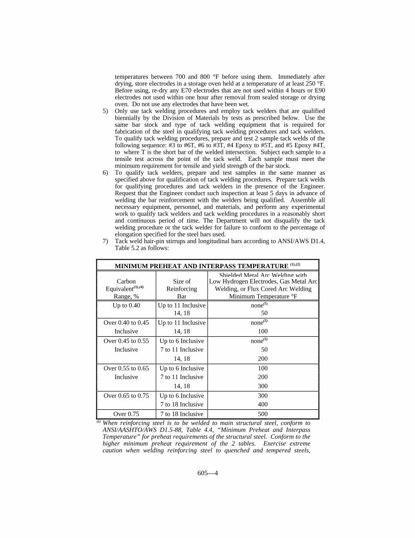
605—4
temperatures between 700 and 800 °F before using them. Immediately afterdrying, store electrodes in a storage oven held at a temperature of at least 250 °F.Before using, re-dry any E70 electrodes that are not used within 4 hours or E90electrodes not used within one hour after removal from sealed storage or dryingoven. Do not use any electrodes that have been wet.
5) Only use tack welding procedures and employ tack welders that are qualifiedbiennially by the Division of Materials by tests as prescribed below. Use thesame bar stock and type of tack welding equipment that is required forfabrication of the steel in qualifying tack welding procedures and tack welders.To qualify tack welding procedures, prepare and test 2 sample tack welds of thefollowing sequence: #3 to #6T, #6 to #3T, #4 Epoxy to #5T, and #5 Epoxy #4T,to where T is the short bar of the welded intersection. Subject each sample to atensile test across the point of the tack weld. Each sample must meet theminimum requirement for tensile and yield strength of the bar stock.
6) To qualify tack welders, prepare and test samples in the same manner asspecified above for qualification of tack welding procedures. Prepare tack weldsfor qualifying procedures and tack welders in the presence of the Engineer.Request that the Engineer conduct such inspection at least 5 days in advance ofwelding the bar reinforcement with the welders being qualified. Assemble allnecessary equipment, personnel, and materials, and perform any experimentalwork to qualify tack welders and tack welding procedures in a reasonably shortand continuous period of time. The Department will not disqualify the tackwelding procedure or the tack welder for failure to conform to the percentage ofelongation specified for the steel bars used.
7) Tack weld hair-pin stirrups and longitudinal bars according to ANSI/AWS D1.4,Table 5.2 as follows:
(1) When reinforcing steel is to be welded to main structural steel, conform toANSI/AASHTO/AWS D1.5-88, Table 4.4, “Minimum Preheat and InterpassTemperature” for preheat requirements of the structural steel. Conform to thehigher minimum preheat requirement of the 2 tables. Exercise extremecaution when welding reinforcing steel to quenched and tempered steels,
MINIMUM PREHEAT AND INTERPASS TEMPERATURE (1),(2)
Shielded Metal Arc Welding withCarbon Size of Low Hydrogen Electrodes, Gas Metal Arc
Equivalent(3),(4) Reinforcing Welding, or Flux Cored Arc WeldingRange, % Bar Minimum Temperature °FUp to 0.40 Up to 11 Inclusive none(5)
14, 18 50Over 0.40 to 0.45 Up to 11 Inclusive none(5)
Inclusive 14, 18 100Over 0.45 to 0.55 Up to 6 Inclusive none(5)
Inclusive 7 to 11 Inclusive 5014, 18 200
Over 0.55 to 0.65 Up to 6 Inclusive 100Inclusive 7 to 11 Inclusive 200
14, 18 300Over 0.65 to 0.75 Up to 6 Inclusive 300
7 to 18 Inclusive 400Over 0.75 7 to 18 Inclusive 500
605—5
satisfy the preheat requirements for both. If not possible, do not use weldingto join the two base metals.
(2) Do not weld when the ambient temperature is lower than 0 °F. When the basemetal is below the temperature listed for the welding process being used andthe size and carbon equivalent range of the bar being welded, preheat so thecross section of the bar for not less than 6 inches on each side of the joint is ator above the specified minimum temperature. Ensure preheat and interpasstemperatures are sufficient to prevent crack formation.
(3) After welding is complete, allow bars to cool naturally to ambient temperature.Do not accelerate cooling.
(4) Determine the carbon equivalent of as follows:
(a) Where it is impractical to obtain chemical analysis, assume the carbonequivalent to be above 0.75%. Ensure certified prestressed plant furnisheson the mill test report, the carbon equivalent for each heat of reinforcingsteel intended to be tack welded.
(b) For all steel bars, except those designated as ASTM A706, calculate thecarbon equivalent using the chemical composition, as reported in the milltest report, using the following formula:
C.E. = %C + %Mn/6 (Eq. 1)
(c) For steel bars designated ASTM A706, calculate the carbon equivalent usingthe following formula:
C.E. = %C + %Mn/6 + %Cu/40 + %Ni/20 + %Cr/10 - %Mo/50 - %V/10(Eq. 2)
Ensure the carbon equivalent does not exceed 0.55% (for ASTM A706bars only).
(d) When the base metal is below 32 °F, preheat it to at least 68 °F and maintainat this temperature during welding.
605.03.05 Special Requirements for Prestress Plants. A) Hot Weather Production. In addition to the requirements of Subsection 605.03,
ensure that the producer applies the following requirements to outdoor prestressoperations:
1) When the ambient temperature is above 80 °F sprinkle or fog spray coarseaggregates.
2) Discontinue concreting operations when ambient temperatures are between90 and 100 °F if the producer cannot effectively maintain form and concretetemperatures below 90 °F.
3) Discontinue concreting operations when ambient temperatures are above100 °F.
B) Drawings. Have the producer submit drawings conforming to applicablerequirements of Subsection 607.03 for prestressed girders. Include with the shopdrawings a detailed drawing, including the total number of stirrups, for eachdifferent mark number and a diagram of the detensioning procedure. TheDepartment will not require reproducible drawings. Obtain the Department’scompleted drawing review prior to releasing fabrication.
C) Safety Measures. Ensure that the producer takes effective safety measures toprevent injuries to personnel due to the breakage of strands or failure ofanchorage devices during the tensioning operations. Ensure that the producer
605—6
provides adequate protection that allows the Inspector to perform his normalduties. The Inspector will report any safety precautions deemed inadequate to theDivision of Materials. The Inspector will abide by the safety rules established bythe producer, provided that they do not interfere with his normal duties.
D) Prestressing. Ensure that the producer performs prestressing by pretensioningand provides a skilled technician knowledgeable of the pretensioning systemused.
Ensure that the producer conforms to the following:
1) Uses approved jacking equipment to perform prestressing.2) When using hydraulic jacks, equips them with calibrated pressure gages.
Calibrates the combination of jack and gage to an accuracy of ± 2 percent,and furnishes a graph or table showing the calibration to the Engineer. Ifusing other types of jacks, furnishes calibrated proving rings or other devicesto accurately determine jacking forces.
3) Accurately holds prestressing elements in position to stress by jacks.4) Applies an initial force to each strand in beams or girders such as to develop
a stress of 189,000 psi or such other stress as specified in the Plans.5) Maintains a record of the jacking force and elongations produced thereby.6) If desired, cast several units for precast sections in one continuous line, but
stress them one at a time.7) Does not transfer prestressing forces to any member or release end anchors
before the concrete has attained a minimum compressive strength of 4,000psi, as determined by tests of standard cylinders cured identically as themember. The Department may require a higher strength.
8) Removes forms and detensions prestressed members immediately afterdiscontinuing steam curing or heat curing while the concrete is still warmand moist, when using either of these methods for curing.
9) Cuts or releases the elements in an order that minimizes the lateraleccentricity of the prestressing.
10) The Engineer will reject beams or girders having honeycomb of such extentto affect their strength or resistance to deterioration.
11) Makes an allowance of 0.0005 times the length for shortening of beams andgirders as a result of shrinkage and elastic change.
E) Curing. Cure according to Subsection 605.03.06 except the producer maydiscontinue curing after the concrete reaches the detensioning strength.
F) Removal From Forms. The producer may remove and store precast,prestressed members from the casting beds after the prestress force has beenapplied, provided the Engineer approves arrangements for curing and protecting.Ensure that the producer conforms to the following:
1) Fills all air voids in the inclined surfaces of all I beams with grout.2) Ensures that strand hold-down devices that remain in place are either a
minimum of 1/2 inch from the surface of the concrete or are galvanized.3) Patches all cavities.4) The producer may use other type devices when the Engineer approves them.
Complete all finishing operations on prestressed bridge beams within 48hours of detensioning, except masonry coating, curbs, and damage repair asthe Engineer directs.
605.03.06 Curing. Cure members either by water curing according to Subsection601.03.17 or by rapid curing with low pressure steam or radiant heat.
Perform low pressure steam curing or radiant heat curing under an enclosure capableof adequately containing the live steam or radiant heat. Use enclosures that allow freecirculation of steam or heat about the sides, ends, and tops of members and are constructedto contain the live steam with a minimum moisture loss. The Department will allow the
605—7
use of tarpaulins or similar flexible covers that remain in good repair. Secure thetarpaulins in a manner that prevents the loss of significant steam and moisture. Allowconcrete to attain its initial set before applying the steam or heat. After placing theconcrete, allow an initial set period of not less than 2 hours before applying the steam orheat. When using water reducing and retarding admixtures, increase the initial set periodto 4 hours. The Department will allow determination of the time of initial set using ASTMC 403 and waive the time limits specified herein when the initial set has been reached asdetermined by the referenced test. Prevent surface drying during the period betweenplacing the concrete and applying the steam or heat by covering the members after castingor by keeping the exposed surfaces wet with a fog spray or a double layer of wet burlap.During the waiting period, do not allow the temperature within the curing chamber to fallbelow 50 °F. Use live steam or radiant heat to maintain the curing chamber at the properminimum temperature.
During the initial application of live steam or radiant heat, allow the ambienttemperature within the curing enclosure to increase at an average rate not exceeding 40 °Fper hour until reaching the curing temperature within the enclosure. Do not allow themaximum curing temperature within the enclosure to exceed 160 °F.
Apply live steam on the concrete forms in a manner that does not cause localized hightemperatures.
Apply radiant heat using pipes circulating steam, hot oil, or hot water. Performradiant heat curing under a suitable enclosure to contain the heat, and minimize moistureloss by covering all exposed concrete surfaces with a plastic sheeting. Provide a method ofmaintaining moisture satisfactory to the Engineer.
Water cure precast, non-prestressed, non-post-tensioned items for 3 days or rapid curethem with steam or heat overnight. The Department will allow curing to cease when theacceptance strength is reached as shown by test cylinders.
605.03.07 Removal of Forms and Surface Finish. The Department will allow theremoval of side forms at any time when no distortion, slump, or misalignment of theconcrete will result. Ensure that all surfaces are free from rough, open, or honeycombedareas, and appreciable depressions or projections. Finish or chamfer edges as directed.When removing the forms, avoid spalling or otherwise damaging the concrete. Finishmembers that will be exposed in the finished work according to Subsection 601.03.18.Repair vents opened to relieve air pressure in box beams during curing using non-shrinkgrout.
605.03.08 Dimensional Tolerances. Ensure that the producer furnishes memberswithin the tolerances of the following tables. The Engineer will condition final acceptanceupon satisfactory placement of the units in the structure.
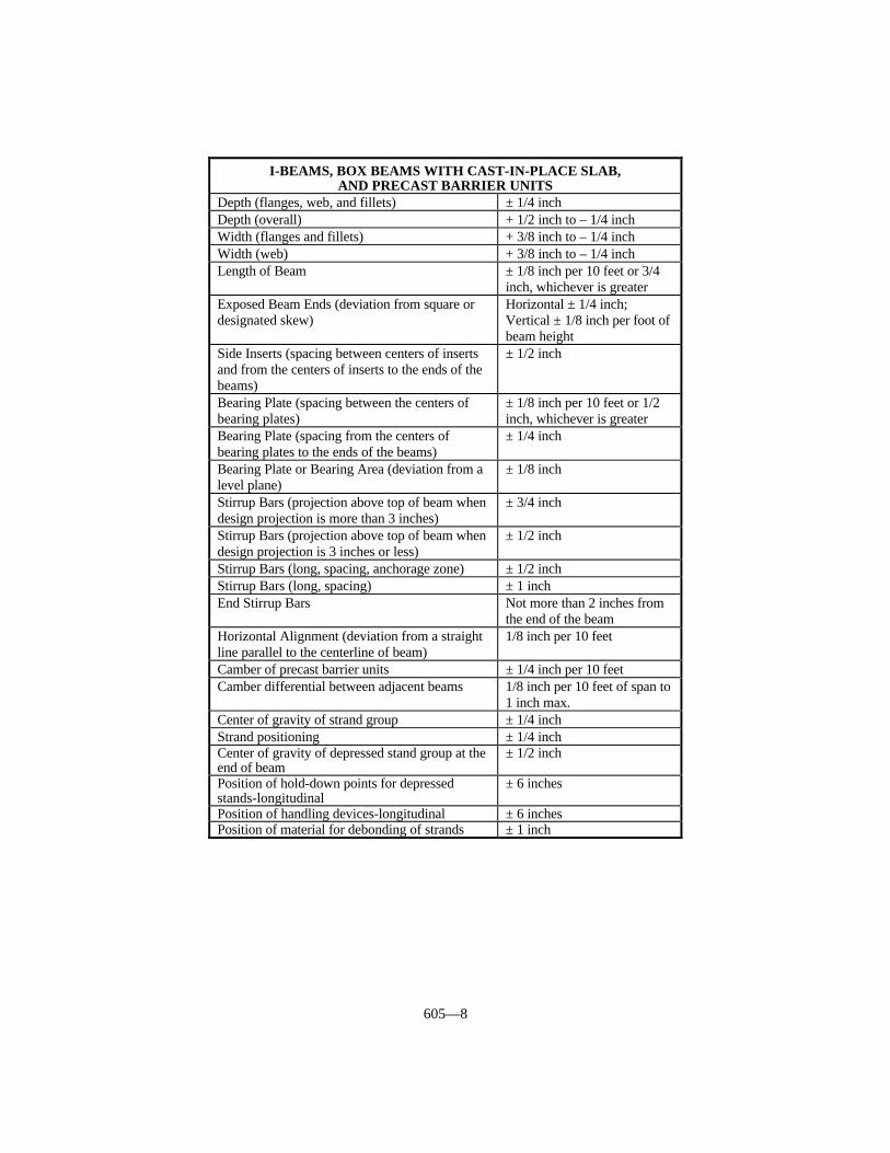
605—8
I-BEAMS, BOX BEAMS WITH CAST-IN-PLACE SLAB,AND PRECAST BARRIER UNITS
Depth (flanges, web, and fillets) ± 1/4 inchDepth (overall) + 1/2 inch to – 1/4 inchWidth (flanges and fillets) + 3/8 inch to – 1/4 inchWidth (web) + 3/8 inch to – 1/4 inchLength of Beam ± 1/8 inch per 10 feet or 3/4
inch, whichever is greaterExposed Beam Ends (deviation from square ordesignated skew)
Horizontal ± 1/4 inch;Vertical ± 1/8 inch per foot ofbeam height
Side Inserts (spacing between centers of insertsand from the centers of inserts to the ends of thebeams)
± 1/2 inch
Bearing Plate (spacing between the centers ofbearing plates)
± 1/8 inch per 10 feet or 1/2inch, whichever is greater
Bearing Plate (spacing from the centers ofbearing plates to the ends of the beams)
± 1/4 inch
Bearing Plate or Bearing Area (deviation from alevel plane)
± 1/8 inch
Stirrup Bars (projection above top of beam whendesign projection is more than 3 inches)
± 3/4 inch
Stirrup Bars (projection above top of beam whendesign projection is 3 inches or less)
± 1/2 inch
Stirrup Bars (long, spacing, anchorage zone) ± 1/2 inchStirrup Bars (long, spacing) ± 1 inchEnd Stirrup Bars Not more than 2 inches from
the end of the beamHorizontal Alignment (deviation from a straightline parallel to the centerline of beam)
1/8 inch per 10 feet
Camber of precast barrier units ± 1/4 inch per 10 feetCamber differential between adjacent beams 1/8 inch per 10 feet of span to
1 inch max.Center of gravity of strand group ± 1/4 inchStrand positioning ± 1/4 inchCenter of gravity of depressed stand group at theend of beam
± 1/2 inch
Position of hold-down points for depressedstands-longitudinal
± 6 inches
Position of handling devices-longitudinal ± 6 inchesPosition of material for debonding of strands ± 1 inch
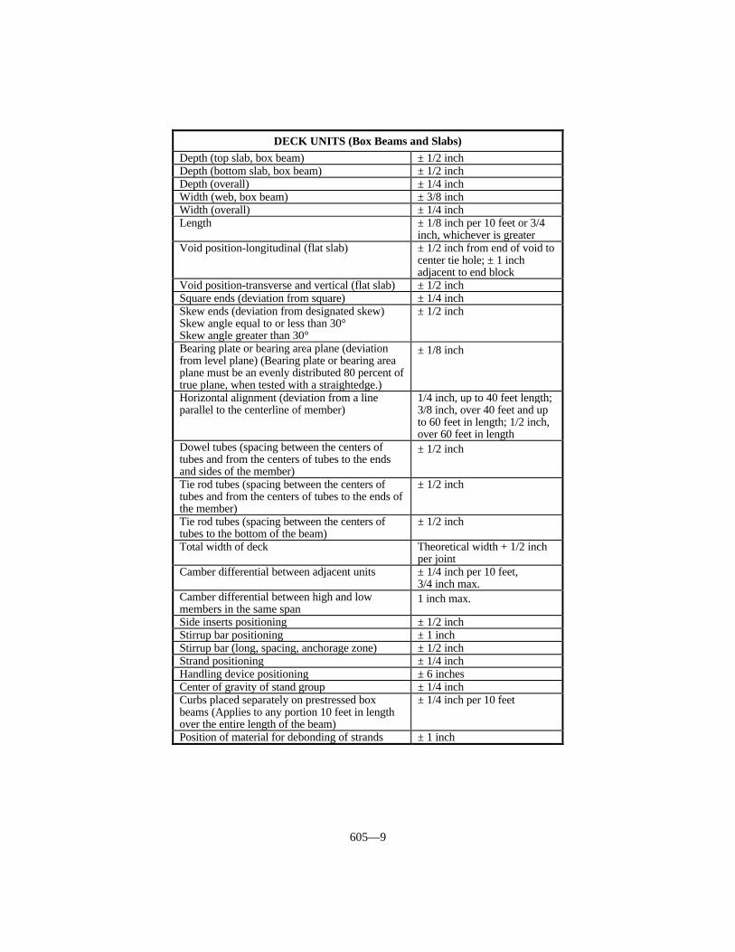
605—9
DECK UNITS (Box Beams and Slabs)Depth (top slab, box beam) ± 1/2 inchDepth (bottom slab, box beam) ± 1/2 inchDepth (overall) ± 1/4 inchWidth (web, box beam) ± 3/8 inchWidth (overall) ± 1/4 inchLength ± 1/8 inch per 10 feet or 3/4
inch, whichever is greaterVoid position-longitudinal (flat slab) ± 1/2 inch from end of void to
center tie hole; ± 1 inchadjacent to end block
Void position-transverse and vertical (flat slab) ± 1/2 inchSquare ends (deviation from square) ± 1/4 inchSkew ends (deviation from designated skew)Skew angle equal to or less than 30°Skew angle greater than 30°
± 1/2 inch
Bearing plate or bearing area plane (deviationfrom level plane) (Bearing plate or bearing areaplane must be an evenly distributed 80 percent oftrue plane, when tested with a straightedge.)
± 1/8 inch
Horizontal alignment (deviation from a lineparallel to the centerline of member)
1/4 inch, up to 40 feet length;3/8 inch, over 40 feet and upto 60 feet in length; 1/2 inch,over 60 feet in length
Dowel tubes (spacing between the centers oftubes and from the centers of tubes to the endsand sides of the member)
± 1/2 inch
Tie rod tubes (spacing between the centers oftubes and from the centers of tubes to the ends ofthe member)
± 1/2 inch
Tie rod tubes (spacing between the centers oftubes to the bottom of the beam)
± 1/2 inch
Total width of deck Theoretical width + 1/2 inchper joint
Camber differential between adjacent units ± 1/4 inch per 10 feet,3/4 inch max.
Camber differential between high and lowmembers in the same span
1 inch max.
Side inserts positioning ± 1/2 inchStirrup bar positioning ± 1 inchStirrup bar (long, spacing, anchorage zone) ± 1/2 inchStrand positioning ± 1/4 inchHandling device positioning ± 6 inchesCenter of gravity of stand group ± 1/4 inchCurbs placed separately on prestressed boxbeams (Applies to any portion 10 feet in lengthover the entire length of the beam)
± 1/4 inch per 10 feet
Position of material for debonding of strands ± 1 inch

605—10
605.03.09 Transportation, Storage, Handling, and Erection. Transport precastgirders in an upright position, and keep the points of support and directions of thereactions with respect to the girder approximately the same during transportation andstorage as when the girder is in its final position.
Prevent cracking or damage during storage, hoisting, and handling of precast units.Replace units damaged by improper storing or handling. Do not ship precast units to theProject prior to attaining the specified acceptance strength.
During erection of members, keep the bridge seats and tops of bearing devices free offoreign materials. While shifting members, lift members completely away from bearings.
Temporarily brace and tie each prestressed concrete I-beam, after erection, in amanner that will prevent sliding, tipping, or other movement that may result from highwinds, creeping down grade, or other causes, until casting the diaphragms. Erect andbrace at least 2 adjacent members in any one span before suspending operations for anyone day.
Begin erecting deck units at the location designated or approved by the Engineer andproceed, one member at a time, across the roadway. After placing and fastening the unitsby transverse tie assemblies, fill longitudinal keys between the units with non-shrink groutand seal as specified in the Plans. Cure the non-shrink grout keys with 2 layers of wetburlap, or other approved covering, placed on the slab. Keep the non-shrink groutcontinuously moist for 3 or more calendar days, except cure commercial mixturesaccording to the manufacturer’s instructions.
Do not place equipment used to lift deck units into place on a portion of the bridgewhich has been erected without obtaining the Engineer’s approval.
605.04 MEASUREMENT. The Department will not measure the work required toqualify the tack welders and tack welding procedures for payment and will consider itincidental to the pay item for prestressed or precast members, except the Department willtest the specimens at no expense to the fabricator.
605.04.01 Precast I-Beams. The Department will measure the quantity in linearfeet. The Department will not measure bearing devices for payment and will considerthem incidental to this item of work.
605.04.02 Precast Panels. The Department will measure the quantity according toSubsection 613.04.
605.04.03 Precast Box Beams. The Department will measure the quantity in linear
PILING
Width or diameter - 1/4 + 3/8 inchHead out of square 1/8 inch per 12 inches of
widthLength of pile ± 1 1/2 inchHorizontal alignment (deviation from a straightline parallel to the centerline of the pile)
1/8 inch per 10 feet
Void position-longitudinal ± 2 inchesVoid position-transverse ± 1/2 inchVoid position-vertical ± 1/2 inchStirrup bars or spiral position ± 1 inchTendon positioning ± 1/4 inchCenter of gravity of strand group ± 1/4 inchHandling device positioning ± 6 inches

605—11
feet. The Department will not measure bearing devices for payment and will considerthem incidental to this item of work.
605.04.04 Precast Concrete Median Barrier. The Department will measure thequantity according to Subsection 508.04.
605.04.05 Precast Piles. The Department will measure the quantity according toSubsection 604.04.
605.04.06 Prestressed Piles. The Department will measure the quantity accordingto Subsection 604.04.
605.04.07 Masonry Coating. The Department will measure the quantity accordingto Subsection 601.04.
605.05 PAYMENT. The Department will make payment for the completed andaccepted quantities under the following:
Code Pay Item Pay Unit8631-8634, 8639 Precast PC I-Beam, Type Linear Foot8635-8638 Precast PC I-Beam Modified, Size Linear Foot8628 Precast PC Panels See Subsection 613.058651-8672 Precast PC Box Beam, Designation Linear Foot1953,1955, 1967, Concrete Median Barrier, Type Linear Foot
1988, 1989, 1992,19998060-8066 Piles-Precast Concrete, Size See Subsection 604.058080, 8082, 8086, 8096 Piles-Prestressed Concrete, Size See Subsection 604.052998 Masonry Coating See Subsection 601.05
The Department will consider payment as full compensation for all work requiredunder this section.
606—1
SECTION 606 BRIDGE RESTORATION ANDWATERPROOFING WITH CONCRETE OVERLAYS
606.01 DESCRIPTION. This work shall consist of bridge deck restoration andwaterproofing with latex concrete or low slump concrete overlays.
606.02 MATERIALS AND EQUIPMENT.
606.02.01 Concrete. Conform to Subsection 601.02 and 601.03.
606.02.02 Latex Admixture. Conform to Subsection 841.
606.02.03 Epoxy for Epoxy-Sand Slurry. Conform to Section 826.
606.02.04 Sand for Epoxy-Sand Slurry. Conform to Subsection 804.
606.02.05 Mortar Sand. Conform to Subsection 804 (for Grout-Bond Coat).
606.02.06 Latex Grout. Conform to Section 601.02.
606.02.07 Joint Materials. Conform to Section 807.
A) Filler. Use preformed expansion joint filler, Type II (cork).B) Sealers. Use rapid cure silicone with closed-cell polyethylene foam back-up rod
compatible with silicone sealant.
606.02.08 Concrete Curing Material. Conform to Section 823.
606.02.09 Structural Steel. Conform to Subsection 812 (for expansion dams andjoint build up).
606.02.10 Equipment. Conform to Subsection 601.02 with the following exceptionsand additions:
A) Mechanical Scarifiers or Grinders. Furnish mechanical scarifiers or grindersdesigned specifically for scarifying bridge decks that the Engineer approves.Ensure that the scarifier or grinder is capable of producing a surface matching theexisting slab cross section and that each pass of the machine matches theprevious pass in elevation.
B) Hammers. Provide hammers weighing 40 pounds or less.C) Mixers. In addition to the requirements of Subsection 601.02, furnish
continuous mixers having a latex admixture supply portion equipped with acumulative-type meter that can be read to the nearest 0.1 gallon. Furnishcontinuous mixers having a water supply portion equipped with a flow meter orother suitable device for calibrating the water supply, and a cumulative typewater meter that can be read to the nearest 0.1 gallon. Ensure that the latex andwater meters are readily accessible, accurate to within ± one percent, and legible.
D) Hand Tools. In addition to the requirements of Subsection 601.02, furnishsufficient hand tools for placement of stiff, plastic concrete capable of workingthe concrete down to approximately the correct elevation for striking off with ascreed.
E) Finishing Machine.
1) Low Slump Concrete Overlays. Ensure that the design of the finishingmachine and the appurtenant equipment is capable of positive machinescreeding of the plastic concrete to within one inch of the face of the existing

606—2
curbs, is of sufficient length to extend at least 6 inches beyond an intendedlongitudinal joint, and is of sufficient length to extend at least 6 inchesbeyond the longitudinal edge of a previously placed overlay. Furnish afinishing machine that is capable of forward and reverse motion underpositive control. Furnish a machine capable of raising the screeds to clearthe screeded surface when traveling in reverse.
a) Support Rails. Furnish a finishing machine having support rails uponwhich the machine travels that is capable of being placed outside thearea to be surfaced and capable of extending beyond each end of thebridge.
b) Strike off. Furnish a finishing machine equipped with a strike off toprovide a uniform thickness of concrete in front of the screeds and with2 oscillating screeds to provide the specified crown.
c) Anchorage. Furnish anchorage for the supporting rails that issubstantial enough to provide for rigid horizontal and vertical stabilityof the rails.
d) Screeds. Ensure that the front oscillating screed is designed tothoroughly consolidate the concrete by vibration to the required density.Install identical vibrators along the length of the front oscillating screedat 5 feet intervals. Furnish a front oscillating screed with a bottomwidth of at least 5 inches and a turned up or rounded leading edge tominimize tearing of the surface of the plastic concrete. Furnish screedswith an effective weight of at least 75 pounds for each square foot ofbottom surface area. Provide each screed with positive control of thevertical position, the angle of tilt, and the slope of the crown. Ensurethat the final screed oscillates and finishes without vibration.
2) Latex Concrete Overlays. Furnish a Department approved machine.
F) Brooms. Furnish brooms having bristles of sufficient stiffness to treat thesurface after finishing.
G) Air Compressors. Furnish air compressors equipped with separators and traps.
605.02.11 Coarse Aggregate. Conform to Section 805, size 9-M.
606.03 CONSTRUCTION.
606.03.01 Scheduling. Notify the Engineer at least 12 hours before placing concretefor the overlay. The Department will not grant a time extension for delay in placingconcrete resulting from the Engineer receiving less than the 12-hour notice.
606.03.02 Weather Limitations. Construct the overlay during the night time hourswhen the ambient temperature will remain below 85 °F, the wind velocity is low, and hotconditions or rain are not expected. During hot weather, place the concrete when theambient temperature falls to 85 °F or below. Complete placement of concrete before theambient air temperature reaches 85 °F. Do not place concrete when the ambienttemperature away from artificial heat is less that 45 °F and falling, except when usingType III cement. Keep all concrete at a temperature above 45 °F for at least 96 hours afterplacing. Make provisions for the uniform distribution of heat, and do not allow any area ofthe concrete surface to be heated to a temperature above 85 °F. To accomplish uniformdistribution of heat during cold weather, provide housing, heating, or insulation methodsthat the Engineer approves. Do not place concrete during rain or drizzle. If it begins torain or drizzle during placement, cease placement and finish and protect the materialalready in place.
606.03.03 Removal of Concrete, Restoration of Reinforcement and Cleaning.

606—3
Treat the entire area of the deck between the curbs (roadway) and the ends of the structure(100 percent of the deck area) by machine preparation consisting of removal of concrete toa depth of at least 1/4 inch below the existing concrete surface. Machine prepare withmechanical scarifiers or grinders. If satisfactory results are not achieved, the Engineer maydirect that the work be performed with other equipment. The Department will not requiremachine preparation on endwalls.
Remove epoxy, asphalt, foreign surfaces, and unsound patches in a manner approvedby the Engineer. Sound concrete patches are to be left in place as determined by theEngineer. Do not use equipment that may cause damage to the underlying concrete.
Remove all other concrete that the Engineer deems unsound. Remove concrete withinareas where the depth of removal exceeds 1/4 inch with hammers or other smallequipment. Do not damage any steel reinforcement. Remove concrete to a depth of 3/4inch below any reinforcing bar which is more than 50 percent exposed or that appears notto be bonded to the existing concrete. Protect any underlying sound concrete and steelreinforcement. Ensure that the periphery of routed areas is as nearly vertical as possible.If the removal of unsound concrete extends through two thirds of the concrete slab or more,remove and replace the remaining sound concrete for full depth patching. Ensure that allexposed steel reinforcement is tied according to Subsection 602.03.04.
Remove all inferior concrete in the deteriorated and spalled areas near joints and alljoint filler. Reform the joints to exact width and true alignment according to Subsection609.03.04 for open joints except when a timber template is used, cover it with polyethylenesheeting.
Blast clean all exposed steel reinforcement and structural steel according toSubsection 606.03.04 to remove scale, rust, grease, oil and other material that wouldprevent adhesion of the concrete. Before placing concrete, replace or supplementdeteriorated or damaged reinforcement as the Engineer directs. Remove all dust and chipsof asphalt materials, concrete, or other debris and clean the entire area with compressedair. Ensure that the compressed air is free of detrimental quantities of water, oil, grease, orany other injurious substances. Do not allow leakage of oil, grease, gasoline, or othersubstances from the compressor or other equipment on the deck. Suspend protectivesheeting such as plastic or tarpaulins under all equipment that leaks.
Remove all spalled or deteriorated concrete in curbs, sidewalks, and plinths to aminimum depth of one inch. Blast clean, coat with a grout-bond coat, and restore to theoriginal section with overlay material. Seal with epoxy-sand slurry.
Partial and/or full depth removal of concrete may be accomplished usinghydrodemolition. Calibrate the hydrodemolition machine to remove only unsoundconcrete. Test the machine on an area of concrete as directed by the Engineer. Usepotable water with a rust inhibitor. Collect and strain all waste water from thehydrodemolition operation. After hydrodemolition operation, sound deck to ensure that allunsound concrete has been removed. Protect all traffic under or adjacent to work area.Protect structural steel paint. Prior to any hydrodemolition operation, submit ahydrodemolition plan, in writing, for approval by the Engineer. In the hydrodemolitionplan state type of machine, water pressure settings and methods to collect and strain wastewater and protect traffic and structural steel.
606.03.04 Blast Cleaning. Blast clean the entire area of the deck surface andvertical faces of curbs, barrier walls, and plinths up to a height of one inch above the topelevation of the overlay, and areas to receive epoxy-sand slurry to a bright, cleanappearance that is free from curing compound, laitance, dust, dirt, oil, grease, asphaltmaterial, paint, and all foreign matter. Perform blast cleaning of an area of the deck withinthe 24-hour period preceding placement of the overlay on the area. If the project is doneunder traffic, perform all blast cleaning within 12 hours prior to placement of the overlay.Perform blast cleaning according to the regulations specified in Subsection 107.01.04.
Protect the blast cleaned areas with white plastic before placement of the overlay.Blast clean contaminated areas and areas exposed more than 24 hours (12 hours whenunder traffic) again as the Engineer directs. Remove or roll the white plastic between themixer truck rear wheels and the overlay placement.

606—4
Hydro blasting may be used in lieu blast cleaning. Use hand held high pressurewands with potable water. Water blast the entire area of the deck. Prevent steelreinforcement from rusting.
606.03.05 Full Depth Patching. Fill full depth holes with Class M1 or M2Concrete. Immediately before placing concrete, dampen and surface dry the contactsurface. Then apply a grout-bond coat by vigorously scrubbing or brushing into thevertical surface of full depth routed areas. Proportion the grout mixture according toSubsection 601.03 using Type I cement. Carefully place the Class M1 or M2 concrete andtamp or vibrate into place. Rough-finish the full depth patched areas to an elevationcorresponding to the scarified grade and cure for a period of no less than 7 calendar days,or until the overlay is placed, by means of a double layer of wetted burlap or similarmaterial. If the full depth patch area is encompassed by an area of partial depth patching,finish the full depth concrete patch to an elevation corresponding to the bottom of thepartial depth routed areas instead of the elevation of the scarified deck.
After the concrete has hardened sufficiently to maintain the proper shape, remove alljoint templates. Avoid chipping or breaking down the edges of the repaired joint. Removeall forming material before completion of the project.
Provide temporary support for existing concrete handrails while removing andreplacing full depth concrete. Submit the proposed method of supporting the handrails tothe Engineer for approval before beginning work.
Blast clean the surfaces of all patched areas and remove sand before constructing theoverlay. Complete all full depth patching in each lane before beginning overlay operationson that lane.
Place latex concrete overlays only when full depth patches have been placed for 24hours or longer. Place low slump concrete overlays only after the full depth patches attaina compressive strength of 3,000 psi. Do not allow construction equipment on the fulldepth patches until they have attained a compressive strength of 4,000 psi.
606.03.06 Partial-Depth Patching. Fill areas in where concrete is routed to partialdepths to the level of reinforcement or below with overlay material and prefill when a lowslump concrete overlay is being used. Cure these areas as the overlay is cured until suchtime as the overlay is placed over the patch or the cure time expires. When latex concreteis used for the overlay, the Department may allow monolithic placement of the partialdepth patches with the overlay.
606.03.07 Prohibited Field Welding. Do not perform welding on load carryingmembers of the bridge without the Engineer’s written consent, and then only in the mannerand at the locations designated.
606.03.08 Mixing and Placing. Mix concrete at the site by either batch orcontinuous mixers as the Engineer approves. Do not use truck mixers on low slumpconcrete overlays. Mix and deliver according to Subsections 601.03.07 and 601.03.08except discharge within 20 minutes.
Submit to the Engineer for approval proposed methods for anchoring the finishingmachine supporting rails to the deck.
Hold the formation of longitudinal joints and transverse joints to a minimum. Whenconstructing longitudinal or transverse joints, thoroughly blast clean and coat with grout-bond coat material before placing plastic concrete against the hardened sides of the joints.Form longitudinal joints using a longitudinal header secured to the deck, 1/4 inch less inthickness than the overlay. Locate longitudinal joints along lane lines. After removal ofthe header, saw the overlay longitudinally 3 inches or more inside the formed edge andremove the portion of the overlay outside the saw cut before placing the adjacent portion ofthe overlay. The Department may allow alternate methods of constructing joints on latexoverlays.
Produce the mixture at a uniform rate and perform finishing immediately after mixing.
606—5
606.03.09 Brooming. Immediately after finishing, broom the surface of the overlaytransversely across the bridge deck from curb to curb. Texture the surface according toSubsection 609.03.10 immediately after finishing on new structure overlays, whenspecified in the Contract, and on Federal Aid projects.
606.03.10 Epoxy-Sand Slurry. After the overlay has been completed and cured,apply a thin coat (approximately 1/16 inch) of an epoxy-sand slurry to the 12 inches of theoverlay adjacent to the curbs, concrete barrier walls, or other vertical walls. Extend theepoxy-sand slurry up the faces of the curbs and walls or other vertical walls and extend theepoxy-sand slurry up the faces and tops of the curbs and plinth according to the StandardDrawings. Thoroughly blast clean to a bright appearance and dry the areas to receive theepoxy-sand slurry before applying the slurry. Apply the slurry only after the deck has beendry for 24 hours. Place strips of masking tape along the joints to prevent the slurry fromentering the joints and to ensure a straight line of slurry. Proportion the slurry as follows:
One Gallon of Component AOne Gallon of Component B2 Gallons of dry, silica sand
The Engineer may allow minor adjustments in the quantity of sand in order to producea more workable mixture. Thoroughly mix the ingredient materials for 3 to 5 minutes.Then spread the slurry and use a squeegee to completely fill the blast cleaned pitted areas,cracks, and rough surfaces. Finish the slurry to a thickness of no more than 1/16 inch.Sprinkle silica sand very lightly over the slurry to provide skid resistance.
The Department will allow placement of thoroughly mixed neat epoxy according toSubsection 510.03.
606.03.11 Cleaning and Sealing Joints. Rework each joint according to theStandard Drawings and as follows:
A) Joint Preparation. Remove any old sealant and joint filler. Use tools andtechniques as approved by the Engineer.
When joint is dry, sandblast to remove all contaminants. Sandblast eachjoint a minimum of 2 passes, one for each face, with nozzle held at an angle tothe joint face and within 1 to 2 inches of the pavement. After sandblasting, airblast each joint to remove sand and other contaminants. Air blast in only onedirection to prevent recontamination of the joint. Compressed air used for airblasting will be at a pressure of at least 90 psi. The air compressor used will beequipped with traps capable of removing moisture, and oil from the air. Applyprimer as recommended by the sealant’s manufacturer.
B) Sealant Filler and Installation. Seal joints on same day that preparation occurs.When joints are prepared, but not sealed on the same day, sandblasting, removalof sand and debris, and primer application will be repeated as directed by theEngineer. Also any joint that has become contaminated will be recleaned asdirected by the Engineer.
Prior to installation of sealant, each joint will be inspected by the Engineerfor proper depth, width, alignment, and cleanliness. Install sealant at a minimumof 1/2 inch below the pavement face and in accordance with the manufacturers’recommendations.
606.03.12 Bridge End Transitions. Overlay the end sections of the bridge andfinish as follows:
A) Rigid Approach. Set the finishing machine rails to provide a 50-foot transitionon the ends of the bridge to match the finished grade of the overlay with theexisting grade of the adjacent pavement. Remove the existing concrete asnecessary to maintain the minimum specified thickness of the overlay.
606—6
B) Non-Rigid Approach or a Rigid Approach with Asphalt Overlay. TheDepartment will not require a transition.
606.03.13 Expansion Dam Treatment. Treat the existing expansion damsaccording to the Standard Drawings. The Department will not require painting ofstructural steel.
606.03.14 Material Hauling. Haul all material for latex concrete or low slumpconcrete overlays with vehicles which do not exceed the regulation for either the legal axleweights or axle spacing contained in 603 KAR 5-066. Prior to doing any overlay work ona structure, furnish to the Engineer a certified statement listing the empty weight of eachhauling vehicle, axle weights when empty, axle weights when fully loaded, gross weight ofeach vehicle when loaded with a specific number of cubic yards, and the spacing of axles.The Engineer will use this information for the purpose of determining the allowablequantity of materials to be hauled. The Engineer will determine the allowable quantity ofmaterials to be hauled based on the capacity and condition of the bridge after the removalof unsound concrete and prior to the placement of the overlay. Under no circumstanceswill the Department allow loads which exceed legal gross or axle load limits.
606.03.15 Damage to Structures. Take responsibility for all damage to thestructure during construction until all work is completed, including the replacement ofentire spans that fail as a result of this construction.
606.03.16 Unacceptable Work. When the Engineer deems necessary, theDepartment will core any areas of the overlay that display extensive cracking or othercharacteristics indicating the waterproofing effectiveness or expected life of the overlaymay be reduced, or that the overlay may not be intimately bonded to the underlying deck.Remove and replace with acceptable concrete all areas shown by the cores to either havecracks exceeding a depth of 1/4 inch or to not be intimately bonded to the underlying deckThe Engineer may require removal and replacement without coring when significantcracking or lack of bond are apparent. Seal all cracks that are not significant enough torequire removal of the overlay with a latex grout as the Engineer directs.
Correct all individual areas of hardened grooved concrete of 25 square feet or larger inwhich the texture is unsatisfactory using methods the Engineer approves.
606.03.17 Special Requirements for Latex Concrete Overlays.
A) Existing Bridges and New Structures.
1) Prewetting and Grout-Bond Coat. Thoroughly and continuously wet theblast cleaned areas to receive the overlay with water at least one hour beforeplacing the overlay is started. Keep the areas wet and cooled with wateruntil placing the overlay.
Disperse or remove all accumulations of water before applying thegrout-bond coat. Immediately ahead of placing the overlay mixture,thoroughly brush and scrub a thin coating of the latex concrete mixture to beused for the overlay onto the wetted surface as a grout-bond coat. Do notallow accumulations of coarser particles of the mixture which cannot bescrubbed into intimate contact with the surface.
Apply the grout-bond coat only for a short distance in advance ofplacing the overlay. Do not allow the grout-bond coat to show any signs ofdrying before placing the overlay. Thoroughly recoat all areas showingsigns of drying with fresh grout.
2) Proportioning and Requirements. Proportion as follows:When adjusting, ensure the mixture contains no less than 658 pounds
per cubic yard of cement nor less than 24.5 gallons per cubic yard of latexadmixture.
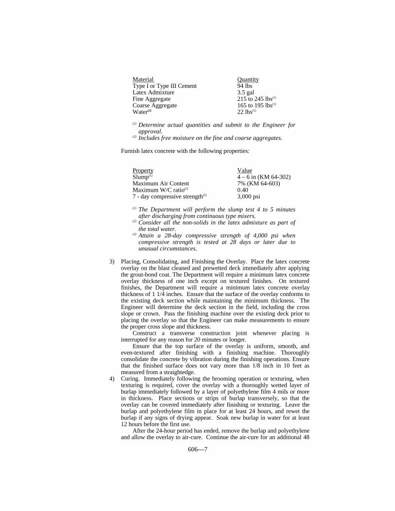
606—7
Material QuantityType I or Type III Cement 94 lbsLatex Admixture 3.5 galFine Aggregate 215 to 245 lbs(1)
Coarse Aggregate 165 to 195 lbs(1)
Water(2) 22 lbs(1)
(1) Determine actual quantities and submit to the Engineer forapproval.
(2) Includes free moisture on the fine and coarse aggregates.
Furnish latex concrete with the following properties:
Property ValueSlump(1) 4 – 6 in (KM 64-302)Maximum Air Content 7% (KM 64-603)Maximum W/C ratio(2) 0.407 - day compressive strength(3) 3,000 psi
(1) The Department will perform the slump test 4 to 5 minutesafter discharging from continuous type mixers.
(2) Consider all the non-solids in the latex admixture as part ofthe total water.
(3) Attain a 28-day compressive strength of 4,000 psi whencompressive strength is tested at 28 days or later due tounusual circumstances.
3) Placing, Consolidating, and Finishing the Overlay. Place the latex concreteoverlay on the blast cleaned and prewetted deck immediately after applyingthe grout-bond coat. The Department will require a minimum latex concreteoverlay thickness of one inch except on textured finishes. On texturedfinishes, the Department will require a minimum latex concrete overlaythickness of 1 1/4 inches. Ensure that the surface of the overlay conforms tothe existing deck section while maintaining the minimum thickness. TheEngineer will determine the deck section in the field, including the crossslope or crown. Pass the finishing machine over the existing deck prior toplacing the overlay so that the Engineer can make measurements to ensurethe proper cross slope and thickness.
Construct a transverse construction joint whenever placing isinterrupted for any reason for 20 minutes or longer.
Ensure that the top surface of the overlay is uniform, smooth, andeven-textured after finishing with a finishing machine. Thoroughlyconsolidate the concrete by vibration during the finishing operations. Ensurethat the finished surface does not vary more than 1/8 inch in 10 feet asmeasured from a straightedge.
4) Curing. Immediately following the brooming operation or texturing, whentexturing is required, cover the overlay with a thoroughly wetted layer ofburlap immediately followed by a layer of polyethylene film 4 mils or morein thickness. Place sections or strips of burlap transversely, so that theoverlay can be covered immediately after finishing or texturing. Leave theburlap and polyethylene film in place for at least 24 hours, and rewet theburlap if any signs of drying appear. Soak new burlap in water for at least12 hours before the first use.
After the 24-hour period has ended, remove the burlap and polyethyleneand allow the overlay to air-cure. Continue the air-cure for an additional 48

606—8
hours when using Type I cement or an additional 24 hours when using TypeIII cement at an ambient air temperature of 50 °F or more.
When the overlay has cured, give the tops of all longitudinal andtransverse construction joints a thorough coating of grout of the sameproportions as the latex concrete mixture used for the grout-bond coatmaterial. Neatly and uniformly apply a 2-inch wide or wider coating to sealany minute cracks at these locations. Do not use epoxy-sand slurry to sealconstruction joints in lieu of grout.
The Department will allow the overlay to be opened to traffic as soon ascuring is completed, all full depth patches are at least 7 days old or haveattained a compressive strength of 4,000 psi, all construction joints aresealed, and gutterline and curb slurry is applied.
B) Special Requirements for New Structures. Construct according to A) abovewith the following exceptions and additions:
1) The Department will not require machine preparation of the top 1/4 inch ofthe deck.
2) Construct an overlay having a thickness of 1 1/2 inch.3) Texture the overlay surface according to Subsection 609.03.10.4) Perform operations in the following sequence: blast clean the existing deck;
apply the grout-bond coat; mix, place, and consolidate the overlay mixture;finish; texture; cure; seal joints and cracks; then apply the epoxy-sand slurry.
5) Do not overlay the deck until it is at least 14 calendar days old.6) When longitudinal construction joints are necessary, completely cure each
section of the overlay before placing the adjacent section of the overlay.
606.03.18 Special Requirements for Low Slump Concrete Overlays.
A) Existing Bridges and New Structures.
1) Grout-Bond Coat. After the concrete surface has been blast cleaned andimmediately before placing the concrete overlay mixture on the deck,vigorously scrub a thin coating of bonding grout into the dry, clean surfaceareas. Do no wet the surface areas before applying the grout. When thebridge deck is exposed to rain before the application of grout, delay theapplication until the bridge deck has dried a minimum of 4 hours and to thesatisfaction of the Engineer. Proportion the grout with water and one partcement to one part mortar sand. Adjust the water to produce a wet slurrymixture to a consistency that is suitable to apply with a stiff brush or broomin a thin, even coating that will not run or puddle in low spots. Ensure thatall areas of the blast cleaned deck receive a thorough, even coat of grout andthat no excess grout collects in any areas. Apply the grout-bond coat onlyfor a short distance in advance of placing the overlay. Do not allow thegrout-bond coat to show any signs of drying before placing the overlay.Thoroughly recoat all areas showing signs of drying with fresh grout.
2) Proportioning and Requirements. Proportion low slump concrete to contain8.75 bags of cement and no more than 35 gallons per cubic yard of water,including free moisture on the aggregates. Use enough water to maintainthe required slump except do no use more than 35 gallons per cubic yard.Attain a 7-day compressive strength of 5,000 psi.
Use an approximate percent fine to total aggregate of 50 as theEngineer approves. Incorporate the aggregate into the mixture as theEngineer directs.
Add water-reducing admixture according to the manufacturer’srecommendations.
Use the amount of air-entraining admixture necessary to achieve 5.5 ±

606—9
1.5 percent as determined according to KM 64-302.Maintain a slump as determined according to KM 64-302 of 3/4 inch.
The Department will perform the slump test 4 to 5 minutes after dischargefrom the mixer. The Department may allow a slump tolerance of ± 1/4 inch.The Department will not accept concrete having a slump of more than 1inch. The Department may accept concrete having a slump less than 1/2inch when the finishing machine can finish and consolidate the concreteaccording to the requirements of this section. Meet slump requirements atboth the site of mixing and at the time of placing.
3) Placing, Consolidating, and Finishing the Overlay. Construct a low slumpoverlay having a minimum thickness of 1 1/2 inch. For overlays requiringtexturing, construct an overlay having a minimum thickness of 1 3/4 inch.The Engineer will determine the deck section in the field, including the crossslope or crown. Pass the finishing machine over the existing deck beforeplacing the overlay so that the Engineer can make measurements to ensurethe proper cross slope and thickness.
Promptly after applying the grout-bond coat, deposit the concrete on thedeck. Then strike off and consolidated with the finishing machine.
The Department may require consolidation using hand-held vibratorswhen placing the mixture around steel reinforcement or structural steelmembers. Construct a transverse construction joint whenever placing isinterrupted for 20 minutes or longer, for any reason.
First strike off the concrete at 1/4 inch or more above the specified finalthickness, and then consolidated by vigorous mechanical vibration. TheDepartment will determine the in-place density of the consolidated mixtureby nuclear gages immediately following the screeding operation; theDepartment will adjust the determined in-place density using the followingformula:
Adjusted Density = in-place density x 0.945 1.00 - actual air content(1)
(1) Express actual air content as a decimal.
Provide concrete with an adjusted density equal to or exceeding thetarget density of 99 percent of the maximum theoretical density calculatedassuming an entrained air content of 5.5 percent. Immediately correct areasof concrete of deficient density by additional passes of the finishingmachine. When any concrete cannot be consolidated to the specifieddensity, remove it and replace with acceptable concrete. The Engineer mayrequire hand finishing of the consolidated concrete with a float in order toproduce a tight uniform surface.
4) Curing. Cure the overlay immediately after texturing or brooming. Curewith a double layer of wetted burlap. Place sections or strips of burlaptransversely so that the overlay can be covered immediately after texturing.Continuously and thoroughly wet the burlap by automatic fogging orsprinkling equipment for at least 96 hours after the curing is started. Soaknew burlap in water for at least 12 hours before the first use. Do not usemembrane curing compound.
When the overlay has cured, give the tops of all longitudinal andtransverse construction joints a thorough coating of grout of the sameproportion and consistency as the grout-bond coat material. Neatly anduniformly apply a minimum 2-inch wide or wider coating to seal any minutecracks at these locations. Do not use epoxy-sand slurry to seal constructionjoints in lieu of grout. The Department will allow the overlay to be openedto traffic as soon as the curing is complete.
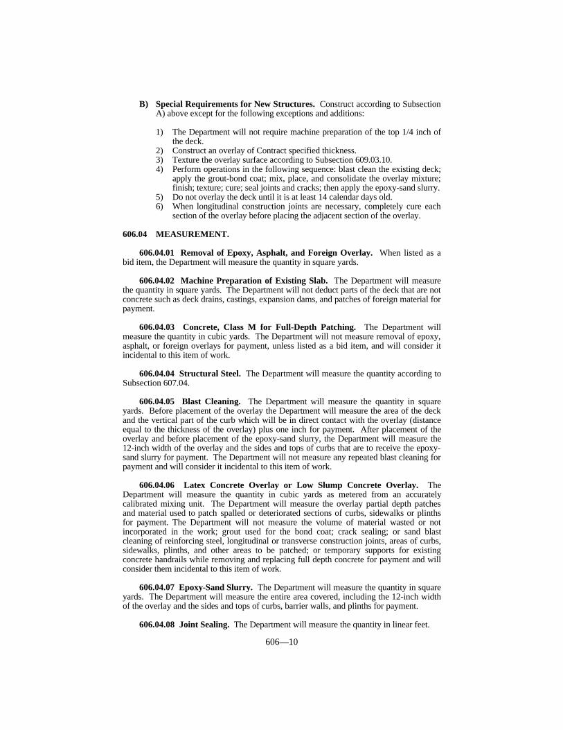
606—10
B) Special Requirements for New Structures. Construct according to SubsectionA) above except for the following exceptions and additions:
1) The Department will not require machine preparation of the top 1/4 inch ofthe deck.
2) Construct an overlay of Contract specified thickness.3) Texture the overlay surface according to Subsection 609.03.10.4) Perform operations in the following sequence: blast clean the existing deck;
apply the grout-bond coat; mix, place, and consolidate the overlay mixture;finish; texture; cure; seal joints and cracks; then apply the epoxy-sand slurry.
5) Do not overlay the deck until it is at least 14 calendar days old.6) When longitudinal construction joints are necessary, completely cure each
section of the overlay before placing the adjacent section of the overlay.
606.04 MEASUREMENT.
606.04.01 Removal of Epoxy, Asphalt, and Foreign Overlay. When listed as abid item, the Department will measure the quantity in square yards.
606.04.02 Machine Preparation of Existing Slab. The Department will measurethe quantity in square yards. The Department will not deduct parts of the deck that are notconcrete such as deck drains, castings, expansion dams, and patches of foreign material forpayment.
606.04.03 Concrete, Class M for Full-Depth Patching. The Department willmeasure the quantity in cubic yards. The Department will not measure removal of epoxy,asphalt, or foreign overlays for payment, unless listed as a bid item, and will consider itincidental to this item of work.
606.04.04 Structural Steel. The Department will measure the quantity according toSubsection 607.04.
606.04.05 Blast Cleaning. The Department will measure the quantity in squareyards. Before placement of the overlay the Department will measure the area of the deckand the vertical part of the curb which will be in direct contact with the overlay (distanceequal to the thickness of the overlay) plus one inch for payment. After placement of theoverlay and before placement of the epoxy-sand slurry, the Department will measure the12-inch width of the overlay and the sides and tops of curbs that are to receive the epoxy-sand slurry for payment. The Department will not measure any repeated blast cleaning forpayment and will consider it incidental to this item of work.
606.04.06 Latex Concrete Overlay or Low Slump Concrete Overlay. TheDepartment will measure the quantity in cubic yards as metered from an accuratelycalibrated mixing unit. The Department will measure the overlay partial depth patchesand material used to patch spalled or deteriorated sections of curbs, sidewalks or plinthsfor payment. The Department will not measure the volume of material wasted or notincorporated in the work; grout used for the bond coat; crack sealing; or sand blastcleaning of reinforcing steel, longitudinal or transverse construction joints, areas of curbs,sidewalks, plinths, and other areas to be patched; or temporary supports for existingconcrete handrails while removing and replacing full depth concrete for payment and willconsider them incidental to this item of work.
606.04.07 Epoxy-Sand Slurry. The Department will measure the quantity in squareyards. The Department will measure the entire area covered, including the 12-inch widthof the overlay and the sides and tops of curbs, barrier walls, and plinths for payment.
606.04.08 Joint Sealing. The Department will measure the quantity in linear feet.
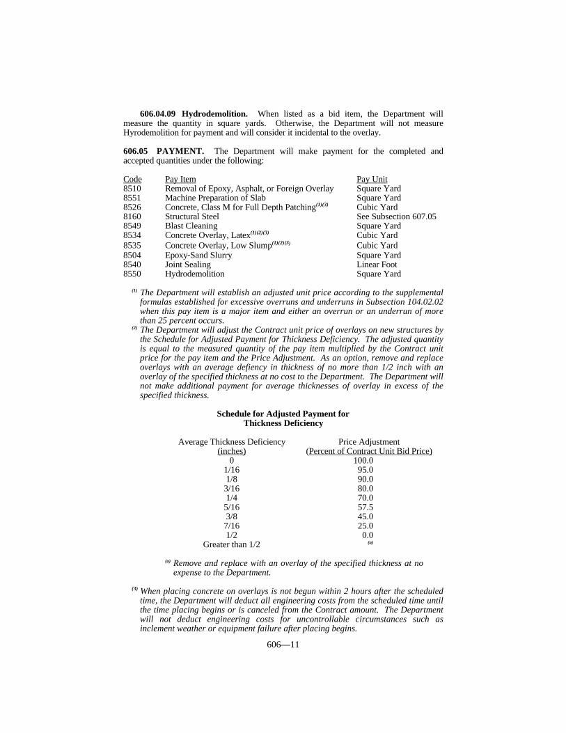
606—11
606.04.09 Hydrodemolition. When listed as a bid item, the Department willmeasure the quantity in square yards. Otherwise, the Department will not measureHyrodemolition for payment and will consider it incidental to the overlay.
606.05 PAYMENT. The Department will make payment for the completed andaccepted quantities under the following:
Code Pay Item Pay Unit8510 Removal of Epoxy, Asphalt, or Foreign Overlay Square Yard8551 Machine Preparation of Slab Square Yard8526 Concrete, Class M for Full Depth Patching(1)(3) Cubic Yard8160 Structural Steel See Subsection 607.058549 Blast Cleaning Square Yard8534 Concrete Overlay, Latex(1)(2)(3) Cubic Yard8535 Concrete Overlay, Low Slump(1)(2)(3) Cubic Yard8504 Epoxy-Sand Slurry Square Yard8540 Joint Sealing Linear Foot8550 Hydrodemolition Square Yard
(1) The Department will establish an adjusted unit price according to the supplementalformulas established for excessive overruns and underruns in Subsection 104.02.02when this pay item is a major item and either an overrun or an underrun of morethan 25 percent occurs.
(2) The Department will adjust the Contract unit price of overlays on new structures bythe Schedule for Adjusted Payment for Thickness Deficiency. The adjusted quantityis equal to the measured quantity of the pay item multiplied by the Contract unitprice for the pay item and the Price Adjustment. As an option, remove and replaceoverlays with an average defiency in thickness of no more than 1/2 inch with anoverlay of the specified thickness at no cost to the Department. The Department willnot make additional payment for average thicknesses of overlay in excess of thespecified thickness.
Schedule for Adjusted Payment forThickness Deficiency
Average Thickness Deficiency Price Adjustment(inches) (Percent of Contract Unit Bid Price)
0 100.01/16 95.01/8 90.03/16 80.01/4 70.05/16 57.53/8 45.07/16 25.01/2 0.0
Greater than 1/2 (a)
(a) Remove and replace with an overlay of the specified thickness at noexpense to the Department.
(3) When placing concrete on overlays is not begun within 2 hours after the scheduledtime, the Department will deduct all engineering costs from the scheduled time untilthe time placing begins or is canceled from the Contract amount. The Departmentwill not deduct engineering costs for uncontrollable circumstances such asinclement weather or equipment failure after placing begins.

606—12
The Department will consider payment as full compensation for all work requiredunder this section.
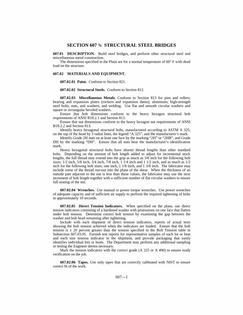
607—1
SECTION 607 STRUCTURAL STEEL BRIDGES
607.01 DESCRIPTION. Build steel bridges, and perform other structural steel andmiscellaneous metal construction.
The dimensions specified in the Plans are for a normal temperature of 60° F with deadload on the structure.
607.02 MATERIALS AND EQUIPMENT.
607.02.01 Paint. Conform to Section 821.
607.02.02 Structural Steels. Conform to Section 812.
607.02.03 Miscellaneous Metals. Conform to Section 813 for pins and rollers;bearing and expansion plates (rockers and expansion dams); aluminum; high-strengthsteel bolts, nuts, and washers; and welding. Use flat and smooth circular washers andsquare or rectangular beveled washers.
Ensure that bolt dimensions conform to the heavy hexagon structural boltrequirements of ANSI B18.2.1 and Section 813.
Ensure that nut dimensions conform to the heavy hexagon nut requirements of ANSIB18.2.2 and Section 813.
Identify heavy hexagonal structural bolts, manufactured according to ASTM A 325,on the top of the head by 3 radial lines, the legend “A 325”, and the manufacturer’s mark.
Identify Grade 2H nuts on at least one face by the marking “2H” or “2HB”, and GradeDH by the marking “DH”. Ensure that all nuts bear the manufacturer’s identificationmark.
Heavy hexagonal structural bolts have shorter thread lengths than other standardbolts. Depending on the amount of bolt length added to adjust for incremental stocklengths, the full thread may extend into the grip as much as 3/8 inch for the following boltsizes; 1/2 inch, 5/8 inch, 3/4 inch, 7/8 inch, 1 1/4 inch and 1 1/2 inch, and as much as 1/2inch for the following bolt sizes; one inch, 1 1/8 inch, and 1 3/8 inch. The fabricator mayinclude some of the thread run-out into the plane of the shear. When the thickness of anoutside part adjacent to the nut is less than these values, the fabricator may use the nextincrement of bolt length together with a sufficient number of flat circular washers to ensurefull seating of the nut.
607.02.04 Wrenches. Use manual or power torque wrenches. Use power wrenchesof adequate capacity and of sufficient air supply to perform the required tightening of boltsin approximately 10 seconds.
607.02.05 Direct Tension Indicators. When specified on the plans, use directtension indicators consisting of a hardened washer with protrusions on one face that flattenunder bolt tension. Determine correct bolt tension by examining the gap between thewasher and bolt head remaining after tightening.
Include with each shipment of direct tension indicators, reports of actual testsshowing the bolt tension achieved when the indicators are loaded. Ensure that the bolttension is ± 20 percent greater than the tension specified in the Bolt Tension table inSubsection 607.03.05. Furnish test reports for representative samples of each lot or heatand each size tension indicator in the shipment, and provide packaging that easilyidentifies individual lots or heats. The Department may perform any additional samplingor testing the Engineer deems necessary.
Mark the tension indicators with the correct grade (A 325 or A 490) to ensure readyverification on the job.
607.02.06 Tapes. Use only tapes that are correctly calibrated with NIST to ensurecorrect fit of the work.
607—2
607.03 CONSTRUCTION.
607.03.01 Shop Drawings and Welding Procedures. Submit to the Division ofBridge Design detailed shop drawings and welding procedures. The Department willfurnish plans showing sufficient details to prepare detailed shop drawings. Includewelding procedures and details, when required, as part of the shop drawings. TheDepartment will not consider the shop drawing review process to be complete without thesubmittal of welding procedures. Make all drawings on sheets of 0.003 inch minimumthickness mylar film, 22 inches or 24 inches wide by 36 inches in length. Ensure that finaldrawings provide clear, sharp lines on prints. If applicable, use photo reproductions onphoto sensitive film. Submit to the Division of Bridge Design 3 full or half size sets (6 forrailroad bridges) of prints of the detailed shop drawings and welding procedures. TheDivision of Bridge Design will return one set of reviewed shop drawings with all requiredcorrections noted. When corrections are necessary, submit 3 full or half size sets of printsof the corrected drawings. After final review, furnish to the Division of Bridge Design 10full or half size sets of correct shop drawing prints. After fabrication is complete and theEngineer has approved the structural steel for shipment, furnish to the Engineer onefull-size set of the reviewed shop drawings, including the welding procedures, which willproduce clear prints and microfilms.
Do not make any changes to any drawing after the Engineer has reviewed it withoutthe Engineer’s written approval or written direction.
Only make substitutions of sections different from those shown on the drawings whenthe Engineer approves in writing.
Although the drawings may have been reviewed, take responsibility for thecorrectness of the drawings and for shop fits and field connections.
Take responsibility for any material ordered or work done before the Engineer reviewsthe drawings and welding procedures.
When design drawings differ from the shop drawings, the design drawings govern.When the requirements of this section differs from the shop drawings, the requirements ofthis section govern.
When the design drawings differ from the requirements of this section, the designdrawings govern.
607.03.02 Workmanship.
A) Quality of Workmanship. Ensure that workmanship and finish are equal to theAISC best general practices in modern bridge shops.
B) Storage of Materials. Store structural material, either plain or fabricated, at thefabricating shop above ground upon platforms, skids, or other supports. Keep itfree from dirt, grease, and other foreign matter and protect it from corrosion.
C) Straightening Materials. Before measuring or working rolled material, ensurethat it is straight. When straightening is necessary, use methods that will notinjure the metal. If sharp kinks and bends are evident, the Engineer will rejectthe material.
D) Finish. Provide a neat finish to the work. Shear, flame cut, grind, and chipcarefully and accurately. Remove all burrs resulting from reaming or drilling.
607.03.03 Bolt Holes. Either punch or drill all holes for connections.
A) Punched Work. Punch all holes full-size except:
1) When there are more than 5 thicknesses, or when any of the main material isthicker than 3/4 inch in structural carbon steel, 5/8 inch in high-strength lowalloy steel, or 1/2 inch in quenched and tempered alloy steel, sub-punch allholes, and ream them after assembling according to the requirements of C)below.
607—3
2) When the metal is thicker than the size of the bolts, drill the holes accordingto the requirements of D) below.
3) Sub-punch and ream punched holes for stringer and floor beam fieldconnections according to the requirements C) below, or sub-punch and reamto a metal template no less than one inch thick, without assembling.
4) Sub-punch and ream punched holes in field connections of main truss orarch members, skew portals, skew portal bracing plate, girder spans,continuous I-beam spans and rigid frames. Punch holes in connection platesor other parts of such members according to the requirements of C) below.Main truss members are the top and bottom chords, end posts, and webmembers forming the truss.
B) Punched Holes. Punch full-size holes 1/16 inch larger than the nominaldiameter of the bolt. Do not allow the diameter of the die to exceed the diameterof the punch by more than 3/32 inch. Ensure that holes are cut cleanly withouttorn or ragged edges.
Punch holes so that, after assembling the component parts of a member andbefore reaming, a cylindrical pin 1/8 inch smaller than the nominal diameter ofthe punched hole may be passed through at least 75 of any group of 100contiguous holes, or in like proportion for any smaller group of holes. When 10percent or more of any group of 100 or fewer holes will not pass a pin 3/16 inchsmaller than the nominal diameter of the punched hole, the Engineer will rejectthe mispunched pieces. Ream any holes that must be enlarged to admit bolts.
C) Sub-Punched and Reamed Holes. Punch sub-punched and reamed holes forbolts 3/16 inch smaller than the nominal diameter of the bolts. Ensure that thepunch and die have the same relative sizes as specified for full size punchedholes.
After assembling, ream sub-punched holes to a diameter of 1/16 inch largerthan the nominal diameter of the bolt.
After assembling and firmly bolting pieces forming a built member performreaming. Do not interchange reamed parts.
Ream holes with twist drills or with short taper reamers. Do not directreamers by hand unless the Engineer approves. Use solvents, detergents, or otherEngineer approved means before cleaning and painting, to thoroughly removeany oil or grease used as a reaming lubricant.
D) Drilled Holes. Ensure that drilled holes are 1/16 inch larger than the nominaldiameter of the bolt. However, do not allow drilled holes for turned bolts to bemore than 1/32 inch larger than the diameter of the finished bolt. Hold partssecurely together while drilling assembled members.
Do not use numerical tape or electronic computer controlled drills unless thefabricator can provide a history showing defect free work of this type. Thismeans that previous work was free of misdrilled holes caused by human errors ormachine errors.
Drill holes according to the requirements of E) below. Submit to theEngineer for review with the shop drawings, the proposed procedure for drillingholes and assuring correct fit of members. When using numerical tape orelectronic computer controlled drills, the Department will require shop assemblyof at least 25 percent of the splices and at least 10 percent of floor beam andbracket main member connections as proof of accurate fit. In the event holes donot match as prescribed for the assembled pieces, assemble and ream all splicesto fit and use metal templates to ream all other floor beam connections.
E) Accuracy of Reamed and Drilled Holes. Ensure that reamed or drilled holesare cylindrical and perpendicular to the member. After reaming or drilling, donot allow 85 of any group of 100 contiguous holes, or in like proportion for anysmaller group of holes, to show an offset greater than 1/32 inch between adjacentthicknesses of metal.
F) Edge Distance of Bolts. Maintain a minimum distance from the center of any
607—4
bolt to a sheared or flame cut edge of:For one inch diameters, 1 3/4 inch.For 7/8 inch diameters, 1 1/2 inch.For 3/4 inch diameters, 1 1/4 inch.For 5/8 inch diameters, 1 1/8 inch.
Ensure that the minimum distance from a rolled or planed edge, except inflanges of beams and channels, is:
For one inch diameters, 1 1/2 inch.For 7/8 inch diameters, 1 1/4 inch.For 3/4 inch diameters, 11/8 inch.For 5/8 inch diameters, one inch.
In the flanges of beams and channels, ensure that the distance is:
For one inch fasteners, 1 1/4 inch.For 7/8 inch fasteners, 1 1/8 inch.For 3/4 inch fasteners, one inch.For 5/8 inch fasteners, 7/8 inch.
Ensure that the maximum distance from any edge is 8 times the thickness ofthe thinnest outside plate, but does not exceed 5 inches. If the design drawingsor the Engineer approves in writing, the Department will allow the use ofoversize, short-slotted, and long-slotted holes according to the applicablestructural steel design sections of the AASHTO Standard Specifications forHighway Bridges.
607.03.04 Shop Assembly and Material Traceability. Conform to therequirements of A) through D) below when not using numerical tape or electroniccontrolled drills; conform to E) below for all structural steel fabrication.
A) Assembling Trusses and Other Supports. Assemble trusses, arches, skewportals, skew portal bracing, girder spans, continuous I-beam spans, and rigidframes in the shop, and adjust the parts to line, camber, and fit for drilling orreaming of field connections.
B) Assembling Members. Thoroughly clean surfaces of metal in contact beforeassembly. Before reaming, assemble, well pin, and firmly draw together theparts of a member with bolts. When necessary, take apart assembled pieces toremove burrs and shavings produced by the reaming operation. Ensure thatmembers are free from twists, bends, and other deformation.
Progressively shop assemble each longitudinal girder unit in no less than3 contiguous sections adjusted to line, elevation, camber, and fit for drilling orreaming. Add at least one section at the rear end of the assembly when removingany section from the advancing end to ensure that the assembled portion of thestructure is never less than 3 contiguous sections.
With connected parts assembled, either drill or ream other major boltedconnections to the longitudinal girders in the shop or drill or ream to a metaltemplate without assembly. Keep girder sections assembled until match markedand the Engineer has inspected and approved them.
Do not apply the assembly requirement for drilling or punching toconnections for cross frames, diaphragms, lateral bracing, expansion dams, andother minor members.
C) Drifting of Holes. Only allow drifting during assembly to the extent that itbrings the parts into position, but does not enlarge holes or distort the metal.Ream all holes that must be enlarged. Do not allow reaming to exceed theallowable tolerances.
607—5
D) Match Marking and Identification. Match mark connecting parts assembled inthe shop for the purpose of reaming holes in field connections, according to thediagram shown on reviewed shop drawings. Match mark with 3/8 inch steel,low stress riser dies. Indicate the location of match marks with a circle of paintaround them. Use paint for indicating the location of match marks of a differentcolor than that specified for shop paint.
E) Material Traceability. Ensure that the fabricator can demonstrate by a writtenprocedure and by actual practice a method of material application andtraceability, visible at least through the “fit up” operation, of all elements of ashipping piece. Ensure that the traceability method is capable of verifying propermaterial application as it relates to material specification designation; heatnumber and manufacturer; and material test reports for special requirementswhere required.
In addition, upon completion of fabrication, furnish the Department with alist of each component of each major load-carrying member and the heat numberand manufacturer applicable to the material used for each, including sketches ordiagrams when necessary. Provide this list on drafting film which will produceclear prints and microfilms, and submit it as part of the final shop drawings.
607.03.05 Bolted Connections Using High-Strength Steel Bolts.
A) General. Use friction type joint for all connections made with high-strengthsteel bolts.
To determine the required bolt length, add the grip, the adjustment for boltsize specified in the following table, 3/16 inch for each hardened flat washer, and5/16 inch for each beveled washer. Grip is the total thickness of all connectedmaterials, exclusive of washers. Then round up to the next 1/4 inch length.
The adjustment in the above table allows for manufacturing tolerances andfor the use of a heavy hexagon nut, and provides adequate “stick through” at theend of the bolt.
Provide adequate bolt length to allow for the exposure of at least 2 completethreads beyond the face of the nut after tightening.
Where necessary, clip washers on one side and no closer than 0.875 of thebolt diameter from the center of the washer.
Install bolts with a hardened washer under the nut or bolt head, whichever isthe element turned in tightening. The Department will allow the use of a flatwasher when the abutting surface adjacent to the bolt head or nut does not have aslope of more than 1:20 with respect to a plane normal to the bolt axis. Whereouter faces of the bolted parts have a slope of more than 1:20 with respect to a
BOLT SIZE ADJUSTMENTNominal Bolt Size Adjustment for Bolt Size
(inch) (inch)1/2 11/165/8 7/83/4 17/8 1 1/81 1 1/4
1 1/8 1 1/21 1/4 1 5/81 3/8 1 3/41 1/2 1 7/8

607—6
plane normal to the bolt axis, use a smooth beveled washer to compensate forlack of parallelism.
Ensure that bolted parts fit solidly together when assembled and are notseparated by gaskets or any other interposed compressible material. Keep alljoint surfaces free of dirt, burrs, and other defects that would prevent solidseating of the parts. Maintain contact surfaces free of oil, excess primer, and anyother foreign matter.
Tighten all bolts, with properly calibrated wrenches, to provide at least therequired minimum bolt tension values shown in the following table oncompletion of the joint.
Set the calibrated wrenches used to provide the bolt tension specified in thetable above so as to induce a bolt tension at least 5 percent in excess of thisvalue.
Calibrate the wrenches twice daily by tightening, in a device capable ofindicating actual bolt tension, no less than 3 typical bolts from the lot to beinstalled. Adjust power wrenches to stall or cut-out at the selected tension.When using manual torque wrenches, note the torque indication corresponding tothe calibrating tension and use it in the installation of all bolts of the tested lot.When measuring torque, keep nuts in tightening motion. For short-grip bolts, theDepartment will allow calibration of wrenches by using direct-tension indicatingwashers with solid plates in a manner acceptable to the Engineer.
When using calibrated wrenches to install several bolts in a single joint, usethe wrench to “touch up” bolts previously tightened, which may have beenloosened by tightening of the subsequent bolts, until all are tightened to theprescribed amount.
When required, because of bolt entering and wrench operation clearances,tighten by turning the bolt while preventing the nut from rotating.
Furnish all tension machines and torque wrenches.The Engineer will approve the procedure for calibration of wrenches.Operate a manual torque wrench as the Engineer spot inspects installed
bolts by observing the indicated torque. Use a torque wrench that has beencalibrated as previously described in this subsection. When the Engineer isinspecting bolts, apply the inspecting wrench and its required torque to 10percent of the bolts, but not less than 2 bolts, selected at random in a connection.The Engineer will accept the connection as properly tightened if the nut or bolthead does not turn when applying the required torque. When applying therequired torque and a nut or bolt turns, the Engineer will test all bolts in theconnection. Tighten all bolts whose nut or bolt head is turned by the required
BOLT TENSIONNominal Bolt Size
(inch)Minimum Bolt Tension
ASTM A 325 Bolts(KIPS)
ASTM A 490 Bolts(KIPS)
1/2 12 155/8 19 243/4 28 357/8 39 491 51 64
1 1/8 56 801 1/4 71 1021 3/8 85 1211 1/2 103 148
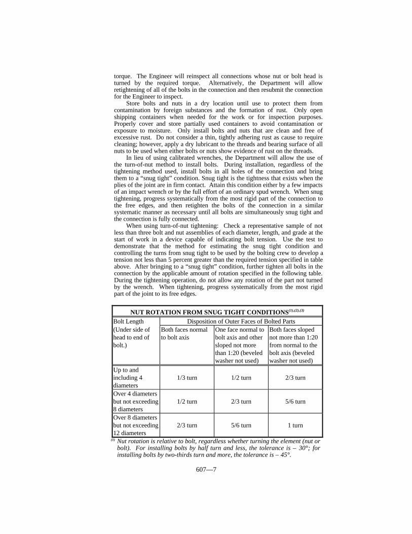
607—7
torque. The Engineer will reinspect all connections whose nut or bolt head isturned by the required torque. Alternatively, the Department will allowretightening of all of the bolts in the connection and then resubmit the connectionfor the Engineer to inspect.
Store bolts and nuts in a dry location until use to protect them fromcontamination by foreign substances and the formation of rust. Only openshipping containers when needed for the work or for inspection purposes.Properly cover and store partially used containers to avoid contamination orexposure to moisture. Only install bolts and nuts that are clean and free ofexcessive rust. Do not consider a thin, tightly adhering rust as cause to requirecleaning; however, apply a dry lubricant to the threads and bearing surface of allnuts to be used when either bolts or nuts show evidence of rust on the threads.
In lieu of using calibrated wrenches, the Department will allow the use ofthe turn-of-nut method to install bolts. During installation, regardless of thetightening method used, install bolts in all holes of the connection and bringthem to a “snug tight” condition. Snug tight is the tightness that exists when theplies of the joint are in firm contact. Attain this condition either by a few impactsof an impact wrench or by the full effort of an ordinary spud wrench. When snugtightening, progress systematically from the most rigid part of the connection tothe free edges, and then retighten the bolts of the connection in a similarsystematic manner as necessary until all bolts are simultaneously snug tight andthe connection is fully connected.
When using turn-of-nut tightening: Check a representative sample of notless than three bolt and nut assemblies of each diameter, length, and grade at thestart of work in a device capable of indicating bolt tension. Use the test todemonstrate that the method for estimating the snug tight condition andcontrolling the turns from snug tight to be used by the bolting crew to develop atension not less than 5 percent greater than the required tension specified in tableabove. After bringing to a “snug tight” condition, further tighten all bolts in theconnection by the applicable amount of rotation specified in the following table.During the tightening operation, do not allow any rotation of the part not turnedby the wrench. When tightening, progress systematically from the most rigidpart of the joint to its free edges.
(1) Nut rotation is relative to bolt, regardless whether turning the element (nut orbolt). For installing bolts by half turn and less, the tolerance is ± 30°; forinstalling bolts by two-thirds turn and more, the tolerance is ± 45°.
NUT ROTATION FROM SNUG TIGHT CONDITIONS(1),(2),(3)
Bolt Length Disposition of Outer Faces of Bolted Parts(Under side ofhead to end ofbolt.)
Both faces normalto bolt axis
One face normal tobolt axis and othersloped not morethan 1:20 (beveledwasher not used)
Both faces slopednot more than 1:20from normal to thebolt axis (beveledwasher not used)
Up to andincluding 4diameters
1/3 turn 1/2 turn 2/3 turn
Over 4 diametersbut not exceeding8 diameters
1/2 turn 2/3 turn 5/6 turn
Over 8 diametersbut not exceeding12 diameters
2/3 turn 5/6 turn 1 turn
607—8
(2) Applicable only to connections in which all material within the turn grip ofthe bolt is steel.
(3) There is no research available to establish the turn-of-nut procedure for boltlengths exceeding 12 diameters. Therefore, determine the required rotationby actual test in a suitable tension measuring device that simulates conditionsof solidly fitted steel.
Perform the rotational-capacity test described in Section 813 on eachrotational-capacity lot prior to the start of bolt installation. Use hardened steelwashers for the test even if they are not required in the actual installationprocedures.
Verify that a visible lubricant is on the threads of galvanized nuts. Ensurethat black bolts are oily to the touch when delivered and installed.
Before installing, clean and relubricate weathered or rusted bolts or nuts notconforming to the requirements of the rotational-capacity test. Retreat recleanedor relubricated nut and washer assemblies to conform to rotational-capacity testrequirements before installing.
Use bolt, nut and washer (when required) combinations from the same lotused for the rotational-capacity test.
B) Direct Tension Indicators. When specified in the Plans, the Department willallow tightening all high-strength bolts in diameters of 1/2 inch through 1 1/4inch inclusive, using direct tension indicators.
Before work begins, furnish the Engineer with the manufacturer’s writteninstallation instructions. Install direct tension indicators, and tighten the boltsaccording to these instructions.
Under normal conditions, install the tension indicator under the non-turnedelement of the fastening system. Obtain the Engineer’s permission beforeinstalling tension indicators under the turned element. If the Engineer determinesthat it is necessary to install the tension indicator under the turned element,install additional hardened washers according to the manufacturer’s instructions.Use bolt lengths sufficient to accommodate the tension indicators and anyadditional washers required.
Do not reuse tension indicators. If it becomes necessary to loosen apreviously tensioned bolt, discard and replace the tension indicator. The fastenerassembly may also need to be replaced.
Furnish a device capable of measuring actual bolt tension. Before workbegins, tighten at least 3 typical bolts and direct tension indicators in the deviceto the correct bolt tension. Keep the tension device available thereafter foradditional checks when the Engineer deems necessary.
The Engineer will inspect bolt installation by inserting a feeler gage into theopening between adjacent flattened protrusions. The Engineer will examine atleast 10 percent, but no less than 2, of the bolts in each connection. The Engineerwill consider the installation acceptable if the gage will not enter the opening.The Engineer will not consider a zero gap as cause for rejection. If the gap is notuniform around the bolt, the Engineer will base acceptance on the average gap.That is, the Engineer will check the gap at several points around the bolt and ifthe gage will not enter the gap on at least half the tries, the installation will beacceptable.
Seal the gap behind the indicator completely with paint. If necessary, usemoisture cure aluminum polyurethane intermediate coat at that location.
Furnish tension indicators in addition to washers when specified in theContract.
607.03.06 Reuse of ASTM A 325 Bolts. The Department will allow the use ofASTM A 325 high-strength bolts one additional time after initially tightening them tospecification tension, provided a close visual inspection indicates no distress in the bolt.This allows ASTM A 325 bolts to remain installed when tightened to specification tension
607—9
twice, one time at original installation and one time at reuse. Do not consider touching upor retightening previously tightened bolts, which may have been loosened by the tighteningof adjacent bolts, as reuse, providing the snugging up continues from the initial position.When removing and loosening a bolt after it has been tightened to specification tensiontwice, discard the bolt and substitute a new bolt.
607.03.07 Welds. Perform all welding, when authorized, according to requirementsspecified in ANSI/AASHTO/AWS D1.5. Do not field weld, except as specified in thePlans, without the Engineer’s written permission.
Ensure that in all cases, welders, welding operators, and tackers have been qualifiedby testing according to KM 64-110 within the previous 24 months of the time of actualweld performance.
607.03.08 Planing and Finishing.
A) Edge Planing. Plane to a depth of 1/4 inch all sheared edges of plates that aremore than 5/8 inch thick and carry calculated stress. The Department will allowfillet re-entranting cuts before cutting.
B) Flame Cutting. Obtain a smooth surface free from cracks and notches, and anaccurate profile using a mechanical guide and the Department will allow flamecutting of steel. Only perform flame cutting by hand where the Engineerapproves. Smooth the surface by planing, chipping, or grinding. Adjust andmanipulate the cutting flame to avoid cutting beyond the prescribed lines. Filletre-entrant cuts to a radius of no less than 3/4 inch. Do not allow the surfaceroughness value of oxygen cut surfaces to be greater than that specified inANSI/ASME B46.1, as follows:
Material Thickness Surface Roughness ValueLess than 4 inch(1) 1,000 MU inch4 to 8 inches 2,000 MU inch
(1) for ends of members not subject to calculated stress at the ends,conform to the surface roughness value of 2,000 MU inches.
Remove roughness exceeding these values and occasional notches or gougesno more than 3/16 inch deep, on otherwise satisfactory surfaces, by machining orgrinding. Leave cut surfaces and edges free of slag. Remove irregularity orunevenness from defects to the oxygen cut surfaces with a slope not exceedingone in 10. Do not repair defects in oxygen-cut edges by welding except with theEngineer’s approval. Perform such weld repairs by suitably preparing the defect,welding with low-hydrogen electrodes not exceeding 3/16 inch in diameter andgrinding the completed weld smooth and flush with the adjacent surface toproduce a workmanlike finish.
Preheat members in the area to be cut to a minimum temperature of 200 °Fto prevent edge cracks. Allow sufficient additional width to permit planing,chipping, or grinding to remove rough, burned, cracked, or otherwise defectiveedges. Grind corners at flame cut edges to a radius of at least 1/16 inch, andremove any evidence of edge cracking by planing, chipping, or grinding to adepth not exceeding 1/4 inch.
C) Heat Curving. The fabricator may either fabricate welded girders by flamecutting the flanges to the required curvature from rectangular plates before fittingand welding to the web, or fabricate welded girders or rolled beams byfabricating straight units and then, through the application of heat to the flangeedges, induce the required curvature. Do not perform heat curving in beams orgirders fabricated from steels that are manufactured to a specified minimum yieldpoint greater than 50,000 psi or in beams or girders having a radius shorter thanthe minimum radius of curvature as determined by the procedures outlined in the
607—10
AASHTO Standard Specifications for Highway Bridges.When the Contract requires heat curving rolled beams or welded girders,
ensure that the work conforms to the following requirements.Curve beams and girders by either continuous or V-type heating. For the
continuous method, simultaneously heat a strip along the edge of the top andbottom flanges. Ensure that the strip is of sufficient width and temperature toobtain the required curvature. For the V-type heating, heat the top and bottomflanges in truncated triangular areas having their bases along the flange edge andspaced at regular intervals along each flange. Determine the spacing andtemperature of the areas necessary to obtain the specified curvature. Apply heatalong the top and bottom flanges at approximately the same rate.
For V-type heating, terminate the apex of each truncated triangular areaapplied to the inside of a flange surface just before reaching the juncture of theweb and the flange. To avoid unnecessary web distortion, carefully heat theinside flange surfaces (the surfaces that intersect the web) to avoid applying heatdirectly to the web. When the radius of curvature is 1,000 feet or more, extendthe apex of each truncated triangular heating area applied to the outside of aflange surface to the juncture of the flange and web. When the radius ofcurvature is less than 1,000 feet, extend the apex of each truncated triangularheating area applied to the outside of a flange surface past the web for a distanceequal to 1/8 of the flange width or 3 inches, whichever is less. Ensure that eachtruncated triangular area has an included angle of approximately 15 to30 degrees; however, do not allow the length of the base of each triangle toexceed 10 inches. Obtain the Engineer’s approval before making any variation inthe patterns as prescribed in this subsection.
For both types of heating, heat the flange areas that will be on the inside ofthe horizontal curve. Concurrently heat both surfaces of flanges when the flangethickness is 1 1/4 inch or greater. Space the heating patterns uniformly along thefull length of each flange to produce a uniform arc of a circular curve in themember. When heating causes a chording effect that the Engineer judges notaesthetically pleasing, ensure that the fabricator reheats the member usingadditional heating patterns as required to obtain the desired results.
Conduct the heat-curving operation so that temperature of the steel does notexceed 1,150 °F. Confine heating to the patterns or areas specified in thissection, and apply heat to bring the steel within the patterns or areas to therequired temperature as rapidly as possible without overheating the steel.Consider any heating procedure which causes a portion of the steel to be heatedto a temperature greater than 1,150 °F as destructive heating and as a possiblecause for rejection of the steel. The fabricator may propose to the Engineervarious means to reaccept, repair, or replace the steel rejected for overheating.The Engineer will review the fabricator’s proposal. Do not artificially cool thesteel until it has cooled naturally to 600 °F. Never quench the steel with water orwater and air. When appropriate, cool the steel with dry compressed air onlyafter it has cooled to 600 °F. The fabricator shall maintain temperature controlsusing temperature indicating crayons or other suitable means during heating andcooling of the steel.
The Department will allow heat curving of beams and girders with the webin either a vertical or horizontal position. When heat curving beams and girdersin the vertical position, brace or support them in such a manner that the tendencyto deflect laterally during the heat-curving process will not cause them tooverturn.
When heat curving beams and girders in the horizontal position, supportthem near the ends and at intermediate points, as required, to obtain a uniformcurvature. Do not allow the bending stress in the flanges due to the dead weightof a beam or girder to exceed 20,000 psi. When a beam or girder is positionedhorizontally for heating, maintain intermediate safety catch blocks at themidlength within 2 inches of the flanges at all times during the heating process to
607—11
guard against a sudden sag due to plastic flange buckling.Heat curve beams and girders in the fabrication shop before painting. The
Department will allow performing of the heat-curving operation either before orafter completing all required welding of transverse intermediate stiffeners.However, unless provisions are made for girder shrinkage, locate and attach allconnection plates and bearing stiffeners after heat curving. When the Engineerrequires longitudinal stiffeners heat curve or flame cut them to the requiredradius and then weld them to the curved girder. When attaching cover plates torolled beams, attach them before heat curving when the total thickness of oneflange and cover plates is less than 2 1/2 inches and the radius of curvature isgreater than 1,000 feet. For other rolled beams with cover plates, heat curve thebeams before attaching the cover plates; either heat curve or oxygen cut coverplates separately and then weld them to the curved beams.
Camber girders before heat curving. Obtain camber for rolled beams byheat-cambering methods approved by the Engineer. For girders, cut the web tothe prescribed camber with suitable allowance for shrinkage due to cutting,welding, and heat curving. The curving process may tend to change the existingvertical camber. This change will be most pronounced when the top and bottomflanges are of unequal widths on a given transverse cross section. However,subject to approval of the Engineer, correct moderate deviations from thespecified camber by a carefully supervised application of heat.
The Engineer will not measure horizontal curvature and vertical camber forfinal acceptance until after the fabricator has completed all welding and heatingoperations and the flanges have cooled to a uniform temperature. The Engineerwill check the horizontal curvature in each edge of each flange with the beam orgirder in the vertical position by measuring offsets from a stringline or wire or byusing other suitable means. The Engineer will check camber by similar means.
D) Facing of Bearing Surfaces. Ensure that the surface finish of bearing and baseplates and other bearing surfaces that are to come in contact with each other orwith concrete conforms to the surface roughness requirements as defined inANSI/ASME B46.1, Part I:
Steel Slabs ANSI 2000Heavy plates in contact in shoes to be welded ANSI 1000Milled ends of compression members, stiffeners, and fillers ANSI 500Bridge rollers and rockers ANSI 250Pins and pin holes ANSI 125Sliding bearings ANSI 125
With the exception of abutting joints and base plates, coat machine-finishedsurfaces with waterproof grease or other approved coating, as soon as practicalafter the Engineer has accepted the structural steel and before removing it fromthe shop. Apply one coat of an approved rust inhibiting primer compatible withthe finished coat instead of zinc rich primer to machine finished surfaces that areto be painted.
E) Abutting Joints. Face abutting ends of compression members and girder flangesaccurately to secure an even bearing when assembled in the structure. Roughfinish ends of tension members at splices to secure close and neat but not contactfitting joints. Where joints are not faced, do not allow the opening to exceed 1/4inch.
F) End Connection Angles. Build floor beams, stringers, and girders having endconnection angles to the exact length specified in the Plans measured between theheels of the connection angles, with a permissible tolerance of + 0 to - 1/16 inch.Where the Contract requires continuity, face end connections. Do not allow thethickness of the connection angles to be less than 3/8 inch, or less than thatshown on the detailed drawings.
G) Finished Members. Ensure that finished members are true to line and free from

607—12
twists, bends, and open joints.H) Web Plates. Cut web plates to provide for camber of the girder. At bolted web
splices, do not allow clearance between ends of web plates to exceed 3/8 inch.I) Fit of Stiffeners. Mill or grind bearing stiffeners of girders and stiffeners
intended as supports for concentrated loads to secure an even bearing against theflanges. Ensure that intermediate stiffeners fit sufficiently tight to exclude waterafter being painted. Ensure that clearance between the ends of horizontalstiffeners and the sides of vertical stiffeners is one inch. Place bearing stiffenersplumb. Place intermediate stiffeners perpendicular to flanges.
J) Bent Plates. Ensure that unwelded, cold-bent, load-carrying, rolled-steel platesconform to the following:
1) Take them from stock plates so the bend line will be at right angles to thedirection of rolling.
2) The radius of bends, measured to the concave face shall not be less andpreferably shall be greater than shown as follows where “T” is the thicknessof the plate:
Angle of Bend Minimum Radius61° to 90° 1.0T91° to 120° 1.5T121° to 150° 2.0T
When a shorter radius is essential, bend the plates while hot at atemperature not to exceed 1,150 °F; except for ASTM A 514 or ASTM A517 steel, in which case bend at a temperature not to exceed 1,125 °F andrequench and temper them. Ensure that hot-bent plates conform to therequirements of 1) above.
3) Before bending, round corners of the plate to a radius of 1/16 inch throughthat portion of the plate where bending is to occur.
607.03.09 Pins and Rollers.
A) General. Accurately turn pins and rollers to the dimensions shown on thedrawings. Furnish pins and rollers that are straight, smooth, and free from flaws.Produce the final surface by a finishing cut, and provide a smooth finishedsurface with an ANSI 125 standard finish.
Forge and anneal pins and rollers more than 7 inches in diameter.In pins larger than 7 inches in diameter, bore a hole 2 inches or more in
diameter full length along the axis after the forging has cooled to a temperaturebelow the critical range. Bore under suitable conditions to prevent injury by toorapid cooling and before being annealed.
Furnish 2 pilot nuts and 2 driving nuts for each size of pin.B) Boring Pin Holes. Bore pin holes true to the specified diameter, smooth and
straight, at right angles with the axis of the member and parallel with each other.Produce the final surface by a finishing cut, and leave the finished surface smoothand polished.
Do not allow the outside-to-outside distance of holes in tension membersand inside-to-inside distance of holes in compression members to vary from thatspecified by more than 1/32 inch. Bore holes in built-up members aftercompleting connections.
C) Pin Clearances. Do not allow the diameter of the pin hole to exceed that of thepin by more than 1/64 inch for pins 5 inches or less in diameter, or 1/32 inch forlarger pins.
607.03.10 Threads for Bolts and Pins. Furnish threads for bolts and pins thatconform to the United States Standard Series UNC-ANSI B1.1, Class 2A for external
607—13
threads and Class 2B for internal threads, except that pin ends having a diameter of 1 3/8inches or more shall be threaded 6 threads to the one inch, and except as required forhigh-strength steel bolts.
607.03.11 Annealing and Stress Relieving. For structural members indicated in theContract to be annealed or normalized, finish machining, boring, and straightening afterheat treatment. Normalize and anneal (full annealing) as specified in ASTM E 44.Maintain temperatures uniformly throughout the furnace during heating and cooling sothat temperatures at points on the members will not differ by more than 100 °F at any onetime.
Maintain a record of each furnace charge that identifies pieces in the charge and liststemperatures and schedule actually used. Provide proper instruments, including recordingpyrometers, for determining temperatures of members in the furnace at any time. Makerecords of the treatment operation available to the Engineer.
Stress relieve members, such as bridge shoes, pedestals, or other parts built up bywelding sections of plates together according to the requirements of AWS D1.5 whenrequired by the Contract.
607.03.12 Forgings. Furnish forgings that are free from internal and external cracksand other harmful defects. The Engineer will determine the method of inspection.
607.03.13 Mill and Shop Inspection and Shipping.
A) Notice of Beginning Work. Designate to the Engineer within 30 dayssubsequent to the award of the Contract the locations of fabricating shops andestimated quantities of steel to be fabricated at each.
The Department will not allow structural steel to be fabricated in more than2 fabricating locations (a location will be considered all shops within one city)unless approved in writing by the Engineer.
The Engineer will not allow any work to be done in the shop before grantingauthorization to proceed. Furnish the Department copies of mill tests andanalyses reports of such structural shapes bearing the manufacturer’s name andheat number. When such identification does not exist, the Engineer may requiresamples for test purposes be cut from the materials. When mill tests andanalyses, or subsequent tests of samples, indicate material does not comply withthis section, the Engineer will reject such materials. When the Engineer rejectsmaterials, furnish suitable material.
B) Facilities for Inspection. Furnish all facilities for inspection of material andworkmanship in the mill and shop, and allow the Inspector free access tonecessary parts of the premises. Notify the Engineer when material is ready forshop inspection.
Furnish power and utilities for operating inspection equipment, provide shopspace for inspection work, handle material as necessary, and enforce requiredsafety precautions for radioactive exposure.
C) Mill Orders, Change Orders, Shipping Statements, Mill Test Reports, andShop Bills. Furnish 3 copies of mill orders, change orders, mill shippingstatements, mill test reports, fabricator’s shop bills (when not attached todrawings), and shipping statements to the Engineer for all structural steelmaterials. Ensure that mill test reports show that all materials conform to thissection and are signed by a responsible representative of the company. Includethe weights of individual members on shipping statements.
D) Facilities for Testing. Furnish test specimens, and all labor, testing machines,and tools necessary to prepare specimens and make full size tests.
E) Rejections. The Inspector’s initial acceptance of any material or finishedmembers will not prevent the Engineer from subsequently rejecting material orfinished members when he determines that they do not conform to the Contract.
F) Weighing of Members. When the Contract specifies that the Department will
607—14
pay for any part of the material by weight, weigh the finished work in thepresence of the Inspector. Supply accurate scales and perform all work involvedin handling and weighing various parts.
G) Marking and Shipping. Paint or mark each member with an erection mark foridentification and furnish an erection diagram with erection marks shownthereon.
Mark the weights of members weighing more than 3 tons on the member.Load structural members on trucks or cars so that they may be transported andunloaded at their destination without being excessively stressed, deformed, orotherwise damaged. Ship girders and store them with the web vertical, unlessthe Engineer allows in writing.
Pack bolts of one length and diameter and loose nuts and washers of eachsize separately. Mark a list and description of contents on the outside of eachcontainer.
H) Handling Material. Conduct loading, transporting, unloading, and storing ofstructural material to maintain it clean and free from injury.
607.03.14 Field Inspection. When the substructure is constructed under a separatecontract, establish lines and elevations for setting steel from the completed substructure.Obtain the Engineer’s approval of the existing lines and elevations prior to submittingshop details for review. The Engineer’s approval of the established lines and elevationsdoes not relieve the substructure contractor from the responsibility for constructing thesubstructure to the lines and elevations shown.
Provide inspection facilities to inspect erection of structural steel. When the Contractdoes not require shop inspection of the structural steel, the Engineer will inspect thematerial and workmanship upon site delivery.
607.03.15 Field Storing and Handling Materials. Place material to be stored onblocking above ground. Maintain it clean and properly drained. Place uniform depthgirders and beams upright. Support long members, such as columns and chords, on skidsplaced to prevent injury from deflection.
Use extreme care in handling the steel at all times to prevent damage of any parts.Insulate the steel from binding chains with approved softeners. Pad the hooks and slingsused to hoist steel. Place the steel so that rubbing will not occur during shipment. Storethe steel at the job site on pallets, or other means approved by the Engineer, so that it doesnot rest on the ground and so that its components do not fall or rest on each other.
607.03.16 Falsework, Erection Methods, and Equipment. Ensure falsework isproperly designed by a Registered Professional Engineer. Construct and maintainfalsework for the loads that will be placed thereon. When required, prepare and submit forreview plans for falsework or for changes in an existing structure necessary formaintaining traffic. Although the Engineer has reviewed these plans, take responsibilityfor the falsework design.
Before starting work present for the Engineer’s review, the proposed method oferection, and the proposed amount and character of equipment to use for erection.Although the Engineer has reviewed this method, take responsibility for safety anderection.
Provide the Engineer with a certification by a Registered Professional Engineer thatfalsework towers have been assembled according to the approved falsework drawingsbefore placing loads on the falsework.
When placing falsework installations adjacent to an open public road, design andprotect the falsework system from errant highway vehicles or from vibration forces causedby passing vehicles.
607.03.17 Bearings and Anchorages. Set all bearing assemblies level and to theelevations specified in the Plans. Make adjustments in the horizontal positions of bearingassemblies for temperature as the Engineer directs. Obtain full bearing on the concrete
607—15
under bearing assemblies regardless of tolerances.Set masonry plates and the bearing plates of bearing assemblies on ground concrete
surfaces, or elastomeric bearing pads, or on lead plates in conformance with the detailsspecified in the Plans.
Immediately before setting bearing assemblies or masonry plates, thoroughly cleanthe surfaces of concrete and metal to be in contact.
Drill the anchor bolt holes to the depth and dimensions specified in the Plans, afterproperly setting the base plates. Keep the holes dry during freezing weather. Do not leador grout anchor bolts until after assembly of each continuous unit or span. After placingthe anchor bolts, pour molten lead into the holes and pack them so the holes will becompletely filled flush to the top of the base plates. Heat anchor bolts prior to pouring thelead to ensure the lead reaches the bottom and to prevent premature cooling.
Ensure that the final adjustment and setting of expansion rockers, rollers, and anchorbolts take into consideration dead load elongation in the span and temperature at the timeof setting. Normal temperature is considered 60 °F. Set rockers so as to be vertical at 60°F, after applying all dead load. Adjust nuts on anchor bolts at the expansion ends ofspans to allow free movement of the span.
When expansion devices such as rockers and expansion dams have been rigidly fixedto hold them in correct alignment, release them immediately upon completing concreteplacement in the portion of the structure they are installed.
607.03.18 Straightening Bent Material. Straighten bent plates and angles or othershapes by methods that will not produce fracture or other injury. Do not heat the metalunless the Engineer allows, in which case do not heat to a higher temperature than 1,150°F as determined by a temperature stick or crayon. After heating and straightening, coolthe metal as slowly as possible. Following straightening, carefully inspect the surface ofthe metal for evidence of fracture. The Department will reject metal with sharp kinks andbends. Do not straighten material by direct hammering.
607.03.19 Field Assembling. Assemble parts accurately as shown, and follow allmatch marks. Handle material so no part will be bent, broken, or otherwise damaged. Donot injure or distort the members by hammering them. Clean bearing surfaces andsurfaces to be in permanent contact before assembling the members. Unless erected by thecantilever method, erect truss spans on blocking that is placed to provide proper camber.Leave blocking in place until tension chord splices and all other truss connections arepinned and bolted, and then release it sufficiently from the falsework to bring compressionchord joints into full bearing.
607.03.20 Pin Connections. Use pilot and driving nuts in driving pins. Drive pinsso that members will take full bearing. Screw pin nuts tight and burr the threads at theface of the nut with a pointed tool.
607.03.21 Misfits. The Engineer will allow the correction of minor misfits usingsmall amounts of reaming, cutting, and chipping. However, immediately report to theEngineer any error in shop fabrication or deformation resulting from handling andtransportation that prevents proper assembly and fitting of parts by moderate use of driftpins or by a moderate amount of reaming and slight chipping or cutting. Obtain theEngineer’s approval of the proposed method for correction. Make the correction in theEngineer’s presence.
For beams or girders that do not conform to the plan camber and grade in the erectedposition, either adjust the depth of the concrete slab haunch over the steel supportingmembers or rework the girder camber to meet the plan grade and slab thickness. Do notallow shear connectors to penetrate the slab less than 2 inches.
607.03.22 Removal of Falsework. Upon completion of erection and before finalacceptance, remove all falsework, excavated or useless materials, rubbish, and temporarybuildings. Replace or renew any fences damaged and restore in an acceptable manner all
607—16
property, both public and private, which may have been damaged during prosecution ofwork. Leave the bridge site and adjacent highway in a neat and presentable conditionsatisfactory to the Engineer. Remove all excavated material or falsework placed in thestream channel during construction before final acceptance.
607.03.23 Cleaning and Painting.
A) General. Furnish a paint system consisting of one shop coat of zinc rich primer,one field coat of moisture cure aluminum polyurethane intermediate coat, and onefield application of urethane finish coat. Furnish a paint system in which allcoats are produced by the same manufacturer. Use tie coats and thinners onlywhen specified or recommended in writing by the manufacturer or the Engineer.When using thinners and tie coats, mix according to the manufacturer’s writtenrecommendation.
Furnish copies of the manufacturer’s technical data sheets, written safetyinstructions, and written application instructions to the Engineer for review andapproval before beginning painting.
Submit written procedures for compliance with this subsection for cleaningand painting in both the shop and the field to the Engineer for approval beforebeginning work. Include at least the following:
1) Cleaning Methods and Equipment. Operating pressure ranges for blastcleaning and water wash equipment.
2) Painting Methods and Equipment. Methods of access for field painting,safety precautions, and traffic control. Address responsibility for damagedue to overspray.
3) Storage and Handling. Methods and equipment for handling and storingpainted truss members and other pieces to prevent coating damage topainted parts.
4) Paint Manufacturer’s Special Instructions. Recommendations for cleaningprimer coated surfaces. Address the possible need for a tie coat beforeapplication of the aluminum polyurethane intermediate coating.Recommendations for the preparation of aluminum polyurethane surfaces toensure adequate bond of subsequent application of urethane finish coatconsidering chalking, catalytic blush, surface hard curing, and recoatwindow.
5) Quality Control Plan. Outline a plan for controlling the quality of thecompleted paint system. Include the following:
a) Name and qualifications of painting supervisors.b) Assurance of authority and responsibility for painting supervisors to
halt operations and make corrections upon discovery of non-conformingwork.
c) Methods of informing painting personnel of the written approvedpainting procedures and their responsibility to comply.
Apply paint only after it has been approved by the Department. TheDepartment may sample and test the paint before delivery or after it is deliveredto the project. When the paint is tested and approved before delivery, theDepartment will label the product containers to indicate approval for use. Whenthe paint is tested and approved after delivery, it must be available for samplingand testing at least 10 calendar days prior to use. Store the paint according toSection 821. The Department will reject the paint when test results indicate thatthe material does not conform to the requirements of this section. Remove allrejected paint from the job before beginning any painting.
Mix coatings with a high shear mixer, such as Jiffy Mixer, or according tothe manufacturer’s instructions to obtain a smooth, lump-free consistency. Do
607—17
not use paddle mixers or paint shakers unless recommended by the paintmanufacturer. Mix in the original containers unless otherwise approved by theEngineer. Continue mixing until all of the metallic powder or pigment is insuspension. Ensure that all of the solids that may have settled to the bottom ofthe container are thoroughly dispersed. When specified by the manufacturer’sproduct data sheet or application instructions, continuously agitate the mixedprimer until applying it.
Spread the paint coatings smoothly and uniformly allowing no excess paintto collect at any point. Paint the contacting surfaces of joints or connections.
When deemed unsatisfactory by the Engineer, remove, clean, and prepareagain all paint work at any stage of its completion.
When necessary or requested by the Engineer, furnish a technicalrepresentative from the paint manufacturer to observe the initial application of allcoatings used, to advise as to proper application techniques, and to determinethat proper results are being obtained. Ensure that the technical representative isalso available to visit the project at all times during the work if the Engineerrequests or deems a visit is necessary.
Keep painted material under cover until the paint is dry or until weatherconditions permit exposure. Apply paint only when the weather is cool enoughso that blistering or formation of a porous film does not occur.
Apply paint coatings using spray nozzles and pressures recommended by theproducer of the coating system to attain the specified dry film thickness.
Provide adequate separators and traps to remove all water and oil fromcompressed air. Perform blotter tests daily in the presence of the Inspector. Paintonly when there is no evidence of moisture or oil in the air lines.
All mil thickness measurements are dry film thickness. Determine dry filmthicknesses with a magnetic dry film thickness gage. Calibrate the dry filmthickness gage on the blasted steel with plastic shims approximately the samethickness as the minimum dry film thickness or with NIST calibration blocks.Use a Tooke film thickness gage to verify the coating thickness on all coatsapplied after the primer. The Engineer will reject the total coating system whenthe Tooke gage shows the primer coat to be less than the specified minimumthickness even when the total dry film thickness exceeds the total of theminimum for all coats.
If the application of the coating at the required thickness in one coatproduces runs, bubbles, or sags, apply the coating in multiple passes of the spraygun. Separate the passes by several minutes. Where excessive coating thicknessproduces mud-cracking of the zinc rich prime in small areas, scrape back tosoundly bonded coating and recoat the area to the required thickness. For largeareas, re-clean and re-prime the surface.
Provide access for proper inspection of the cleaning and painting at both thefabrication plant and the construction site during all phases of work and for aperiod of at least 10 working days after completing each painting section.Furnish, erect, and move scaffolding or appropriate equipment approved by theEngineer, to allow the Inspector to closely inspect all surfaces. Use rubber rollersor other protective devices on scaffold fasteners. Do not use metal rollers or othertypes of fasteners that may mar or damage the freshly coated surfaces.
Comply with all Federal, State, and local regulations relative toenvironmental contamination, safety, and protection of persons and property.
B) Preparation for Shop Coating. After fabrication and immediately beforepainting, remove all areas of oil and grease with a solvent and blast clean allexposed surfaces of the metal, except where galvanized or metalized, accordingto SSPC-SP 10. The Engineer will base acceptance of the surface condition onphotographic standards. Acceptance after blast cleaning and immediately beforepainting, will be according to Pictorial Standards A SP 10, B SP 10, or C SP 10,of SSPC Vis. 1. Ensure that the depth of the anchor texture of the blast-cleaned

607—18
steel is 1.5 to 3 mils. Do not use a wash primer. Apply zinc coating within 24hours after blast cleaning.
Remove all fins, tears, slivers, and burred or sharp edges that are present onsteel members, and that appear during the blasting operation, by grinding andreblasting the area to achieve a 1.5 to 3 mils surface profile.
When removing scale, do not allow the hammers to scar the metal.Use clean dry sand, steel shot, mineral grit, or manufactured grit for a blast
cleaning abrasive. Remove all abrasive and coating residue from the steelsurfaces with a good commercial grade vacuum cleaner equipped with a brush-type cleaning tool, or by double blowing. When using double blowing, vacuumthe top surfaces of all structural steel, including flanges, longitudinal stiffeners,splice plates, hangers, and all other surfaces after completing the double blowingoperations. Blow the steel clean with an air line that has an in-line water trap,and ensure that the air is free of oil and water as it leaves the air line.
Apply paint only after the Engineer inspects and approves the surfaces.Defer painting of galvanized surfaces as long as possible in order that the
surfaces may weather. Before painting galvanized surfaces, treat according toASTM D 2092 or treat with a solution composed of 2 fluid ounces of commercialmuriatic acid added to 2 ounces each of copper chloride, copper nitrate, and salammoniac dissolved in one gallon of water. Prepare the solution in an earthen orglass vessel, never in a metal receptacle. Apply the solution with a wide flatbrush. The galvanized surface will assume a very dark color, drying to a grayishfilm.
C) Application of Shop Coating. Apply one coat of zinc rich primer to all metalsurfaces prior to shipping steel from the plant. Include surfaces that are to befield bolted in contact.
Apply paint only when the air temperature at the shop is 40 °F or greater,the surface temperature of the steel members to be painted is at least 5 °F abovethe dew point temperature, and the relative humidity at the site is between 30 and85 percent. Do not apply paint to damp or frosted surfaces, nor when the air ismisty.
Ensure that the dry film thickness of the prime coat is 3 mils with atolerance of –0.5 mil and + 2.0 mils on all surfaces except those that are to befield bolted in contact or that will be in contact with concrete. Ensure that the dryfilm thickness on surfaces to be field bolted in contact or surfaces that will be incontact with concrete is 1.5 mils ± 0.5 mil except when the slip coefficient isbased on a coating thickness of 5.0 mils. When the slip coefficient is based on a5.0-mil thickness, if desired, apply the prime coat to the full specified thicknessof 3.0 mils with a tolerance of –0.5 and + 2.0 mils.
If the prime coat is deficient in thickness, thoroughly clean with powerwashing equipment, then wire brush, vacuum and recoat according to B) above.
Protect freshly coated primed surfaces from subsequent blast cleaningoperations. When damage occurs, thoroughly wire brush or if visible rust occurs,reblast to a near-white condition. Vacuum and reprime these surfaces byspraying.
Do not apply subsequent coats of paint over the primer until at least72 hours have elapsed or until the film is dry throughout. Apply a shop coat ofzinc rich primer to all steel surfaces that will be in contact with concrete and tosurfaces that will be inaccessible after field assembly. Apply the aluminumpolyurethane intermediate coating and urethane finish coat in the shop beforeassembly or erection in areas that will be inaccessible when assembled in thefield. Apply the shop primer to interior surfaces of box sections that are to besealed by welding. When shear connectors are to be installed in the shop, installthem before painting the top surfaces of girders. After installing the shearconnectors in the shop, repair all heat damage to the shop paint on the bottomsurface of the top flange. The Engineer will not require the repair of heat damageto the top of the flange in contact with concrete. The Engineer will not require
607—19
painting the shear connectors. If the shear connectors are painted, the Engineerwill not require cleaning the overspray. When installing shear connectors in thefield, shop paint the top surface of the girder.
Paint structural steel that is to be welded only after completing welding.When welding the steel in the shop and subsequently erected by bolting, applyone coat of primer after finishing the shop welding and blast cleaning.
Paint surfaces of iron and steel castings only when directed according toSubsection 607.03.08 D).
Transfer or preserve field identification erection marks and weight marks.Load the steel for shipment only after the shop coating has cured at least 72 hoursand the Engineer has inspected it.
D) Preparation for Field Coatings. Clean by sections, bays, or other readilyidentifiable parts of work. Apply paint only after the Engineer has inspected andaccepted each section, bay, or part.
After erection, including all bolting and remedial work, prepare the shopapplied zinc coating for field applied intermediate coating as follows. Removeall grease, oil or other lubricants from all surfaces to be painted includinglubricant or residuals from the surfaces of all galvanized nuts, bolts and washersby solvent cleaning according to SSPC SP 1. When dry overspray from the shopapplied zinc coating exists, remove by sanding. High pressure water wash allstructural steel at 4,500 to 5,000 psi. using clean potable water. As needed, use anon-sudsing, bio-degrable detergent to remove all surface contaminants notremoved by high pressure water washing. Rinse all areas where a detergentand/or solvent was applied by pressure washing with clean potable water. Blastclean all surfaces sustaining damage to the shop applied zinc coating to thepictorial standards described in subsection B. Apply a field coat of approvedzinc rich coating to all areas not possessing an acceptable shop applied zinccoating. Completely remove all rust, scale and other foreign material beforeapplying the intermediate coating.
When application of the finish coat exceeds the recoat window of theintermediate coat, abrade the surface of the intermediate coat according to thecoating manufacturer’s recommendations before applying the finish coat.
E) Application of Field Coatings. Paint between April 1 and November 15. TheDepartment may allow painting at other times when the Engineer approves inwriting.
Apply paint only to clean and dry surfaces when the ambient airtemperature is 40 °F or greater, the surface temperature of the steelmembers to be painted is at least 5 °F above the dew point, and the relativehumidity is less than 90 percent. Do not apply paint to damp or frostedsurfaces, nor during any period of rainfall.
Protect pedestrian, vehicular, and other traffic on or underneath the bridgeand all portions of the bridge superstructure and substructure against damage ordisfigurement by spatters, splashes, and smirches of paint or paint materials.Take responsibility for all damages resulting from paint operations. Submit adetailed written outline to the Engineer for approval before field painting.Include sketches, if necessary, of methods to prevent overspray drift. Includeprotection of vehicular traffic, boats, and marinas beneath the bridge, andbuildings or other property in the vicinity of the bridge.
Apply field coatings only after satisfactorily completing field cleaning andensuring that the paint applied for retouching the shop coat is thoroughly dry. Donot apply succeeding coats until the previous coats have dried throughout the fullthickness of the paint film.
Paint from the top of the structure toward the bottom, and proceed bysections, bays, or parts of the work, unless the Contract or Engineer directsotherwise.
607—20
Apply field coats only at levels greater than 10 feet above the bridge slabuntil completing concrete work, including final rubbing or application of themasonry coating.
Mitigate dust produced by traffic for the necessary distance on each side ofthe bridge. Prevent dust and dirt from coming in contact with freshly paintedsurfaces or other surfaces before applying paint when the Engineer directs.
Apply the intermediate coat to all exposed surfaces of the completedstructure. Ensure that the dry film thickness of the intermediate coating is 2 to 4mils.
Apply urethane finish coat to all exposed surfaces of the completedstructure. Ensure that the dry film thickness of the urethane finish coat is 3.0 ±1.0 mils.
Stencil the completion date of painting, including the year and month, on thestructure as the Engineer directs.
F) Repair of Shop and Field Coatings. Repair according to the manufacturer’srecommendations and as otherwise specified in this section.
When using blast cleaning to field repair coatings, use an approved low-dustabrasive. Apply coating systems for repair as follows:
1) Rusted Areas. Zinc rich primer, aluminum polyurethane intermediate coat,and urethane finish coat.
2) Non-rusted Areas. Organic zinc rich primer only in areas where dry filmthickness of primer coating is less than specified, aluminum polyurethaneintermediate coat, and urethane protective coat.
3) Galvanized Components. Aluminum polyurethane intermediate coat, andurethane protective coat.
When spot repair will not produce a uniform and durable coating, repaintthe entire member as the Engineer directs.
Repair surfaces before erection that will be inaccessible after erection.
607.03.24 Name Plates. When shown, furnish and install name plates includingfastening devices.
607.04 MEASUREMENT. The Department will measure the quantity by the lumpsum. The Department will not measure miscellaneous metals, shop inspections,inspection facilities and equipment, material samples for mill authorization, enforcementof required safety precaution for radioactive exposure, furnishing of technicalrepresentatives for paint, extra paint required when bolting, nameplates, or direct tensionindicators for payment and will consider them incidental to this item of work.
607.05 PAYMENT. The Department will make payment for the completed andaccepted quantities under the following:
Code Pay Item Pay Unit8160 Structural Steel Lump Sum
The Department will adjust the Contract unit price for Structural Steel by thefollowing formula when the Engineer makes plan changes that result in an increase of theestimated plan weight of steel:
Adjusted Contract = Original Contract x (Revised Estimated Plan Weight)Unit Price Unit Price (Original Estimated Plan Weight)
Bear all shop inspection costs incurred at locations other than the 2 originaldesignated locations. The Department will initially pay for the inspection cost. Reimbursethe Department subsequently.

607—21
The Department will consider payment as full compensation for all work requiredunder this section.
The Department will make partial payment for structural steel plate stored at thefabrication shop when requested. This applies to structural steel quantities of 1,000,000pounds or more.

608—1
SECTION 608 CONCRETE BRIDGES
608.01 DESCRIPTION. Construct concrete bridges and parts of other bridges that areconcrete.
608.02 MATERIALS.
608.02.01 Concrete. Conform to Subsection 601.02 and 601.03.
608.02.02 Steel Reinforcement. Conform to Section 811.
608.02.03 Bearing and Expansion Plates. Conform to Section 813. When theContract requires self-lubricating plates, furnish machine surfaces with trepanned recesses.
608.02.04 Rockers. Conform to Section 812.
608.02.05 Elastomeric Bearing Pads. Conform to Section 822.
608.02.06 Preformed Cork Expansion Joint Filler (Type II). Conform to Section807. Use with bearing pads.
608.02.07 Forms. Conform to Subsection 601.02.
608.02.08 Structural Steel. Conform to Section 812.
608.02.09 Masonry Coating. Conform to Section 828.
608.02.10 Anchor Bolts. Conform to Section 813.
608.02.11 Precast and Prestressed Members. Conform to Subsection 605.
608.02.12 Concrete Curing Materials. Conform to Section 823.
608.03 CONSTRUCTION.
608.03.01 Foundation. Begin work after structure excavation, sheet piling, and allbearing piles have been prepared according to Sections 603 and 604.
608.03.02 Falsework and Forms. Construct all falsework and forms according toSubsections 601.03.11 and 601.03.12.
608.03.03 Classes of Concrete for Substructure. Use Class AA concrete inportions of the substructure above the top of caps except pedestals. Use Class A concretein portions of the substructure below the top of caps and in pedestals. When placingconcrete under water, use Class A Modified concrete.
608.03.04 Placing Steel Reinforcement in Substructure. Place steel reinforcementaccording to Subsection 602.03.
608.03.05 Placing Concrete in Substructure. Proportion, mix, and place concreteaccording to Subsection 601.03. Construct construction joints according to Subsection601.03.10. Place concrete for footings to the full depth in one continuous operation, andallow them to set at least 12 hours before placing forms thereon for other parts of thesubstructure unit. Place concrete in columns in one continuous operation betweenconstruction joints. Allow concrete in columns to set at least 12 hours before placingforms for caps. Place concrete for bridge seats according to Subsection 601.03.09.
608—2
Finish all exposed surfaces according to Subsection 601.03.18. Bevel all exposededges 3/4 inch.
Cure according to Subsection 601.03.17.
608.03.06 Placing Anchor Bolts. Place anchor bolts in piers and abutmentsaccording to Subsection 607.03.17.
608.03.07 Setting Expansion Devices. Install bearing and expansion plates, bearingpads, rockers, and other expansion devices, except friction or sliding type, according toSubsection 607.03.17.
For friction or sliding expansion devices furnish either structural steel plates,elastomeric bearing pads, or preformed cork. Firmly anchor expansion devices in correctposition as specified in the Plans. Thoroughly coat all sliding surfaces of expansiondevices with graphite lubricant just before placing them in position. Do not place concretein a manner that will interfere with free movement of the expansion devices.
When preformed cork expansion devices are specified for sliding joints, furnishpreformed cork material that is the full width and depth of each contact surface and is notbuilt up with several pieces or strips.
608.03.08 Protection. Protect the structure during construction. Protect concreteparapet walls of abutments and end bents or ends of concrete spans from damage byequipment or traffic by methods specified in the Plans or as directed. Do not allow anytraffic over the structure from the time it is completed until the pavement is completed,without protecting the ends of the bridge.
608.03.09 Placing Superstructure. Do not place any superstructure on finishedpiers or abutments until attaining the required concrete strength or the table in Subsection601.03.15 for applying significant loads. With the exception of rigid frame structures, donot start the erecting or placing of the superstructure until removing the forms anddetermining the character of concrete in the substructure.
Construct the concrete deck according to Subsection 609.03. Construct the concretebeams according to Subsection 605.03.
608.03.10 Concrete Pile Piers, Steel Pile Piers, and Abutments. Construct allprecast or cast-in-place concrete pile piers and abutments, and steel pile piers andabutments according to the lines, grades, dimensions, and design specified in the Plansand according to Sections 601, 602, and 604. Remove falsework under pier capsaccording to Subsection 601.03.14.
608.03.11 Construction Date and Identification. Stencil the construction date andidentification according to Subsection 601.03.19.
608.03.12 Inspection Facilities. Provide facilities for inspection of work as itprogresses and for final inspection of completed work. Provide ladders, or othersatisfactory means, to enable the Engineer to examine and inspect pier and abutment capsand bearings. Remove them after final inspection and the Engineer’s approval of work.
608.03.13 General Requirements for Superstructure. Give all exposed surfaces afinish according to Subsection 601.03.18. Construct bridge slabs according to Subsection609.03. Construct precast and prestressed beams according to Subsection 605.03.
608.03.14 Steel Reinforcement for Superstructures. Place all steel according toSubsection 602.03.
608.03.15 Concrete Bridge Layout. Dimensions specified in the Plans are for anormal temperature of 60 °F. Layout dimensions are horizontal measurements.
608—3
608.03.16 Permissible Finish Variations. Do not allow lines of the finishedconcrete, except bridge slabs and precast piles, to vary more than 1/4 inch per 10 feet orvary from plan lines more than 0.1 percent of the distance between extremities of the unitconsidered.
The Engineer will decide whether any variations in excess of those stated are causeeither for removal and replacement of the work according to Subsection 105.01.04 or for areduction in payment.
608.03.17 Forms and Steel Reinforcement Quality Control. Perform qualitycontrol according to Section 113. Submit a written plan. Describe inspection procedures.Identify jobsite quality control personnel. Provide qualified QC personnel. Locate theirpersonnel in the management diagram.
Perform a thorough dimensional, grade, and location check of all work prior to eachconcrete placement. Notify the engineer when the inspection is complete and all correctiveactions are taken.
The Engineer will perform the Department quality assurance inspection of forms andsteel reinforcement. Perform corrective work as direct by the Engineer.
608.04 MEASUREMENT.
608.04.01 Concrete. The Department will measure the quantity according toSubsection 601.04.
The Department will not measure furnishing inspection facilities or stenciling forpayment and will consider them incidental to this item of work.
608.04.02 Steel Reinforcement. The Department will measure the quantityaccording to Subsection 602.04.
608.04.03 Structural Steel. The Department will measure the quantity according toSubsection 607.04.
608.04.04 Masonry Coating. The Department will measure the quantity accordingto Subsection 601.04.
608.04.05 Quality Control. Measure and pay according to Section 113.
608.05 PAYMENT. The Department will make payment for the completed andaccepted quantities under the following:
Code Pay Item Pay Unit8100-8105, 2555 Concrete, Class See Subsection 601.05(1)
8150 Steel Reinforcement See Subsection 602.058160 Structural Steel See Subsection 607.052998 Masonry Coating See Subsection 601.05
(1) When the variation is not within the permissible limits and the Engineer doesnot require removal and replacement, the Department will deduct from thetotal Contract price the product of the volume of Concrete not within thepermissible limits multiplied by the Contract unit price for the Concrete.
The Department will consider payment as full compensation for all work requiredunder this section.
609—1
SECTION 609 REINFORCED CONCRETE BRIDGE SLABS
609.01 DESCRIPTION. Construct reinforced concrete slabs on bridges.
609.02 MATERIALS AND EQUIPMENT.
609.02.01 Steel Reinforcement. Conform to Section 811.
609.02.02 Concrete. Conform to Subsection 601.02 and 601.03.
609.02.03 Joint Materials. Conform to Section 807.
609.02.04 Structural Steel Joints. Conform to Section 812.
609.02.05 Forms. Conform to Subsection 601.02.13.
609.02.06 Concrete Curing Materials. Conform to Section 823.
609.02.07 Welded and Seamless Steel Pipe for Bridge Floor Drains. Conform toSection 810.
609.02.08 Zinc Oxide-Zinc Dust Primer. Conform to Federal Specification TT-P-641, Type II.
609.02.09 Finishing Machines. Provide each finishing machine with at least 2movable footbridges from which to perform finishing and curing.
Furnish a self-propelled finishing machine equipped with:
1) one or more augers or other equally effective device to move and position theconcrete,
2) a cylinder to compact and finish the concrete, and3) a pan float.
Provide a machine that is readily adjustable so all its devices may be easily operatedto satisfactorily position, consolidate, and finish the concrete.
Use machines that span the full width of the bridge, are adjustable to gradesparalleling the roadway crown, and are of rigid construction to ensure a surface finish trueto the lines, grades, and cross sections specified in the Plans or established by theEngineer. Give consideration to setting finishing machine on skew if angle exceeds 15degrees.
Support the machine by rails or tracks of sufficient section modulus to withstand theimposed loads and deflect no more than 1/16 inch between the rail supports. Provide railsor track that are sufficiently rigid to prevent the machine from riding up when finishingconcrete of the specified slump. Install the rails outside the limits of the roadway slab, setand maintain them true to grades paralleling the bridge grade, throughout the entirefinishing operation.
609.02.10 Hand Operated Internal Vibrators. Conform to Subsection 601.02.
609.03 CONSTRUCTION.
609.03.01 Swinging the Spans. Before placing concrete slabs on steel spans orprecast concrete release the temporary erection supports under the bridge and swing thespan free on its supports.
609.03.02 Forming. Form according to Subsection 601.03.12. Construct falsework

609—2
according to Subsection 601.03.11. Construct falsework and forms for multiple slab spansto provide the camber required in the finished structure.
Department will allow the use of permanent steel bridge deck forms as follows:
A) Design. Conform to the following criteria for designing permanent steel bridgedeck forms:
1) Design the steel forms on the basis of dead load of form, reinforcement, andplastic concrete plus 50 pounds per square foot for construction loads. Donot allow the unit working stress in the steel sheet to exceed 0.725 of thespecified minimum yield strength of the furnished material, or to exceed36,000 psi.
2) Do not allow deflection under the weight of the forms, the plastic concrete,and reinforcement to exceed 1/180 of the form span or 1/2 inch whichever isless, and do not base this deflection on a total loading of less than 120pounds per square foot.
Base the permissible form camber on the actual dead load condition.Do not use camber to compensate for deflection in excess of the forgoinglimits.
3) Use the design span of the form sheets as the clear span between edges ofsupport angles plus 2 inches measured parallel to the form flutes. Do notuse a fabricated panel length that is less than the distance between edges ofbeam flanges minus 2 inches.
4) Compute physical design properties according to AISI Specification for theDesign of Cold-Formed Steel Structural Members.
5) Maintain the plan dimensions of both layers of primary deck reinforcementfrom each surface of the concrete deck.
6) Do not consider permanent steel bridge deck forms as lateral bracing forcompression flanges of supporting structural members.
7) Except when permitted by the Engineer, do not use permanent steel bridgedeck forms in panels where longitudinal deck construction joints are locatedbetween stringers.
8) Do not weld to any steel girder, stringer, or floor beam; to reinforcementbars in concrete beams; or to form supports fabricated from nonweldablegrades of steel. Protect flanges from damage during erection of forms.
9) Submit fabrication, shop, and erection drawings, with design calculations, tothe Engineer for review. Clearly indicate on these plans the grade of steel,the physical and section properties for all permanent steel bridge deck formsheets, and the locations where the forms are supported.
10) Adjust the steel forms to grade, from the plan construction elevations, toprovide the plan slab thickness with no additional dead load other than thatof the steel forms.
11) Fasten laps between sheets to ensure mortar tightness. Consider direction ofconcrete placement to determine lap orientation.
B) Installation. Install all forms according to approved fabrication and erectionplans.
On steel members, do not rest form sheets directly on the top of the girder,stringer, or floor beam flanges. Securely fasten sheets to form supports with aminimum bearing length of one inch at each end. Place form supports in directcontact with the flange of girder, stringer or floor beam. Make all attachments bypermissible welds, screws, bolts, clips or other approved means. However, donot weld form supports to flanges of steel. Ensure that welding and welds areaccording to the provisions of AWS D 1.5 pertaining to fillet welds, except thatthe Engineer will allow 1/8 inch fillet welds. Welder certification is not required.
Securely fasten all forms to supports while placing them.
609—3
On concrete beams, show all support hardware that is to be cast into thebeam, on the shop drawings. Make attachments to the form supports or to theauxiliary components by permissible welds, screws, bolts, clips, or otherapproved means.
Protect the concrete beam from damage.Clean all form welds of slag and wire brush just before placing the deck
concrete.Thoroughly clean, wire brush, and paint any form metal where the
galvanized coating has been damaged or where white rust has formed on themetal with 2 coats of zinc oxide-zinc dust primer with no color added, to thesatisfaction of the Engineer. It is not necessary to touch up minor heatdiscoloration in areas of welds.
Locate transverse construction joints in the concrete deck slab at the bottomof a flute and field drill 1/4 inch weep holes at not less than one foot on centeralong the line of the joint. Locate the joint and weep holes at the lowest portionof the concrete soffit.
C) Inspection. The Engineer will carefully observe placement of the bridge deckslab. If the Engineer determines that an event such as a delay that may havecaused a cold joint or insufficient vibration of concrete during the placement ofthe concrete warrants inspection of the underside of the deck, remove at least onesection of the forms at a location and time selected by the Engineer to providevisual evidence that the concrete mixture and construction procedures areobtaining the desired results.
When forms are removed for inspection, do not replace the forms, but repairthe adjacent metal forms and supports to present a neat appearance and ensuretheir satisfactory retention. Upon removal of the forms, the Engineer willexamine the concrete surfaces for cavities, honeycombing and other defects. Ifthe Engineer finds irregularities, and determines that these irregularities do notjustify rejection of the work, repair the concrete and give it an ordinary surfacefinish. If the Engineer determines that the concrete where the form was removedis unsatisfactory, remove additional forms, as necessary, for the Engineer toinspect. Modify methods of construction as the Engineer requires to obtainsatisfactory concrete in the slab. Remove or repair all unsatisfactory concrete.
Provide all facilities reasonably required for the safe and convenient conductof the Engineer’s inspection procedures.
609.03.03 Placing and Fastening Reinforcement. Place all steel reinforcement towithin ± 1/4 inch vertically and horizontally of the position shown and according toapplicable requirements of Subsection 602.03. When concrete overlays are included in theoriginal bridge construction, construct according to the tolerance requirements for a newslab. Tie down reinforcing mats securely with wire 0.148 inch or greater in diameter atintervals of no greater than 8 feet in both the longitudinal and transverse directions toprevent upward movement of reinforcement during construction operations. When tied tothe forms, extend the ties through the forms.
Do not deposit any concrete until the reinforcement is in place and the Engineer hasinspected and approved it, and observed a complete and thorough “dry run” with thefinishing machine over the entire slab area to be placed to ensure accurate placement ofsteel top clearance and proper slab depth.
The Engineer may allow splicing the reinforcement according to Subsection 602.03.
609.03.04 Expansion and Fixed Joints. Place all joints according to the detailsspecified in the Plans or as directed. Correct improperly placed joints to the satisfaction ofthe Engineer even when the correction requires removal and replacement.
A) Open Joints. Place open joints in the locations specified in the Plans andconstruct them by the insertion and subsequent removal of a template ofapproved material. Accomplish the insertion and removal of the template
609—4
without chipping or breaking the corners of the concrete. Do not extendreinforcement across an open joint.
B) Steel Joints. Accurately shape the plates, angles, or other structural shapes atthe shop, to conform to the configuration of the concrete slab. Ensure that thesurface in the finished plane is true and free of warping. Employ methods inplacing the joints to keep them in correct position during placement of theconcrete. Set the opening at expansion joints to the temperature adjustmentspecified in the Plans. Avoid impairment of the clearance. When placingconcrete, make adjustments in the joint widths to accommodate temperaturechanges.
C) Cold-Applied or Hot-Applied Sealing Compound. Ensure that all joints to besealed are free of cracked or spalled areas. Chip cracked areas back to soundconcrete.
Ensure that the faces of all joints to be sealed are free of all foreign matter,curing compound, oils, greases, paint, dirt, free water, and laitance. Thoroughlyclean all joint faces by sandblasting or by means of a mechanical rotary wirebrush.
Immediately before sealing, blow out the joint with air from an aircompressor equipped with an oil and water trap. Use an air compressor of suchcapacity as will maintain 90-psi pressure when air is delivered to the jointthrough a nozzle no more than 1/4 inch in diameter.
When any sealing compound has not bonded to the joint wall or face,remove it and clean and reseal the joint.
Place all cold-applied sealing compound with a manufacturer recommendedapplicator, and follow the manufacturer’s mixing and placing instructions.Provide a copy of these instructions and the specifications for the applicator to theDivision of Materials.
D) Preformed Neoprene Joint Seals. Ensure that all joints are true to alignmentand have vertical faces. Ensure that each joint is uniform in width throughout itslength. Reform, reconstruct, and resaw or otherwise modify improperlyconstructed joints to the satisfaction of Engineer.
Construct expansion joints to be sealed by this method according to thedetails shown on the Standard Drawings or specified in the Plans.
When a joint, as constructed, has a width larger or smaller than the specifiedwidth, provide a seal for that joint that is the correct size for the as-built width.
Ensure that all joints to be sealed are free of cracked or spalled concrete.Chip damaged areas back to sound concrete and repair them with an
approved epoxy resin compound or other materials approved by the Department.Install the seals in the properly prepared joints by a tool designed
specifically for installing joint seals. Remove and replace any seal that isdamaged during installation. Remove any seal that is improperly positioned inthe joint and reinstall it at the proper elevation. Use hand methods to install sealsonly in areas that are inaccessible to the machine, or obtain the Engineer’swritten permission to install seals by hand methods.
The Engineer will measure seals before and after installation as a checkagainst stretch. Remove any installed seal that shows more than 5 percentstretch and correctly reinstall it or replace it. Install the seals in structuresimmediately after expiration of the curing period. Install all seals securely andensure that they are free from any objectionable curling or twisting in the jointgroove. Use a lubricant adhesive that covers both sides of the seal over the fullarea in contact with the sides of the joint. Apply the lubricant adhesive either tothe faces of the joint or to the seal, or to both. Install all seals in a highlycompressed state so that the top of the seals is 3/8 ± 1/8 inch below the level ofthe roadway surface. Install the seals in one piece, without field splicing, for thefull length of each of the transverse joints. The Engineer will allow one factorysplice per transverse joint. Obtain the Engineer’s approval for any field splicesrequired by partial width construction.

609—5
When specified for longitudinal joints in structures, install the seals inpractical lengths, without field splicing.
E) Neoprene Expansion Joints. Furnish neoprene expansion joint consisting ofany one of the manufactured joint seals specified in the Plans. Determine whichof the specified joint seals will be used and obtain written approval of jointdetails, prior to placing the deck concrete.
Submit shop drawings for approval according to Subsection 607.03.01.Ensure that these drawings, along with joint details, include a layout plan of thejoint units to be used. Also include procedures for setting expansion joint width,so the opening will be the specified width at 60 °F. The Engineer will approve ofdetails of installation and his decision will be final.
Include the details and material specifications for the manufacturedneoprene expansion joints and incidental accessories, sealants, and adhesiveswith the shop drawings for approval.
Before beginning work on the joint, furnish the manufacturer’s writteninstallation instructions.
Comply with the manufacturer’s installation instructions, apply sealants andadhesives, and install joint units as shown on the approved shop drawings and asspecified in this section.
When the Engineer requests, obtain technical assistance from the supplier ofthe joint. Failure of the joint supplier to provide adequate technical assistancemay be cause for removal of the joint seal from the Department’s List ofApproved Materials.
Remove all forms and debris from the joint opening. Ensure that concrete ormetal surfaces where the neoprene expansion joints are to be set are dry; cleanand free from dirt, grease, and contaminants; level; and sound with no broken orspalled concrete. Ensure that adjacent joint seats are on a straight plane witheach other.
Furnish and install the neoprene strip sealing element in one continuousunbroken length for the entire joint length. For the strip seal type joint, ensurethat the locking groove in the metal extrusion is clean and free of any dirt orcorrosion before installing the neoprene strip seal element. Bond the strip seal inplace with the manufacturer’s recommended adhesive which meets theEngineer’s approval.
Where longitudinal joints cross transverse joint seals, provide a seal byflattening and extending the longitudinal joint neoprene seal element under thetransverse joint pad. When this procedure is not practical, use a separateneoprene apron, bonded to the longitudinal seal element.
Ensure that the finished joint presents a smooth, neat appearance. Wipe orscrape away excess sealant before it becomes hard. Upon completion of an entirejoint, grind any uneven concrete or armored edge.
609.03.05 Drainage. Install deck drains at the locations shown or as directed andplace them before placing the bridge deck slab. Paint all drain pipes according toSubsection 607.03.23. Provide transverse drainage of the roadway surface by means of asuitable crown or cross slope in the floor slab. Effectively drain gutters using weep holesor drain scuppers constructed at locations and in the manner specified in the Plans. Installdrain scuppers to prevent drainage water from staining exposed surfaces of girders andabutment walls. In general, extend drain pipes through the concrete slab to a distance ofno less than one inch below the slab or underlying beam. Provide the under surface ofcantilever brackets and overlapping slabs with a V groove (drip strip) 1/2 inch in depth ata point no more than 6 inches from the outside face of the overhang for the purpose ofarresting flow of moisture to prevent staining.
609.03.06 Weather Limitations and Placing Concrete. Do not place any concretewithin deck slabs during the months of January or February, except for barriers, plinths,curbs, walks, etc. Place all deck concrete according to Subsection 601.03.09. Any time

609—6
the ambient temperature is anticipated to be 85 °F or higher, place concrete in the deckslab during evening hours after ambient temperatures cool to below 85 °F and ceaseplacement before temperatures rise above 85 °F. Cool forms and beams tops by waterspray if their temperature exceeds 85 °F.
Always protect deck placement from rain water being introduced into the concrete andfrom rainwater surface damage. Cease deck placement immediately or cover it forcomplete protection when rain occurs.
609.03.07 Depositing, Consolidating, and Striking Off Slab Concrete. Wet thereinforcing steel and forms with water prior to placing concrete. Deposit the concretebetween the curbs or between the longitudinal joints when specified in the Plans to the fulldepth of the slab, and consolidate it. Consolidate by means of hand-operated internalvibrators according to Subsection 601.03.09. Use a spade in addition to vibrating, ifrequired, to ensure that no honeycomb, voids, or air pockets exist against the forms.Continue consolidating the concrete until there is complete contact between the reinforcingsteel and the concrete, and until mortar flushes to the top surface.
When using permanent steel bridge deck forms, place emphasis on proper vibration ofthe concrete to avoid honeycombing and voids, especially at construction joints, expansionjoints, and valleys and ends of form sheets. Obtain the Engineer’s approval of pouringsequences, procedures, and mixtures.
Continuously place concrete in any slab between expansion joints or betweenconstruction joints as specified in the Plans.
Prevent displacement of reinforcement during placing of concrete. Place concrete inthe sequence as specified in the Plans and in the absence of such designation, place asdirected. Obtain written approval to change the pouring sequence. Provide sufficientwork capacity to place concrete at a minimum rate of 25 cubic yards per hour.
When, in case of an emergency, it becomes necessary to introduce a constructionjoint, form it by means of a vertical bulkhead constructed to produce a keyed joint andlocated as approved by the Engineer.
In placing concrete around steel shapes, place it only on one side of the shape until itflushes up over the bottom flange of the shape on the opposite side, after which place it onboth sides to completion.
Do not place concrete railings monolithic with the slab.On continuous, composite design structures, keep concrete in slabs plastic for a
sufficient length of time to allow the structure to deflect to the natural deflected shape.Place the concrete in each integral unit of the superstructure continuously. Do not
begin placing concrete without sufficient approved material on hand nor without sufficientforces and equipment to complete that unit without interruption. Avoid joints in theconcrete due to work stoppage. Form construction joints, when necessary, according toSubsection 601.03.10.
Place concrete in slab spans in one continuous operation for each span. Placeconcrete in transverse strips the entire width of the bridge. Place concrete for the full depthand ensure that the width of strips is such that concrete in any one strip does not take itsinitial set before placing the adjacent strip.
When expansion devices such as rockers, expansion dams, and similar fixtures havebeen rigidly fixed to hold them in correct alignment, immediately release them uponcompletion of concrete placement in the portion of the structure in which they are installed.
Immediately following consolidation of the concrete, strike off the surface to crownand cross section with the finishing machine. Move the machine in the direction that workis progressing. Maintain a slight excess of concrete at all times so no low spots are left infront of the finishing machine. Prevent the excess concrete from tearing the surface. Afterfinishing, do not work, walk on, or disturb the concrete in place except as described in thissection.
In general, do not add water to the surface of the concrete to assist in finishingoperations. If the Engineer allows the application of water to the surface, apply it as a fogspray using approved spray equipment.

609—7
609.03.08 Working the Surface. Following the striking off or screeding, randomlycheck the surface for irregularities and mortar ridges, at least every 50 feet of bridgelength, with an approved 10-foot straightedge operated parallel to the centerline of thebridge and slab surface. Eliminate all variations greater than 1/8 inch.
After the concrete slab has cured, the Engineer will again check the slab for variationsexceeding 1/8 inch. Perform any corrective action that the Engineer deems necessary.
After completing the finishing operation, ensure that the surface of the concretepresents a uniform appearance; conforms to the required grade and cross section; and isfree from surplus water, rough and porous spots, irregularities, depressions, and otherobjectionable surface features resulting from improper finishing.
609.03.09 Finish with Burlap Drag. If the Contract does not require texturing,finish the slab using a burlap drag. Use a burlap drag of double thickness, at least 3 feetwide, and long enough to span between curb faces. Lay the burlap on the slab surface anddrag it in the direction the slab is being placed, keeping approximately 2 feet of its widthin contact with the slab surface. Keep the burlap drag damp, clean, and free fromhardened concrete.
609.03.10 Texturing. Texture the surface by forming transverse grooves. Form thetransverse grooves by approved manual tools such as rakes with spring steel tines. Formthe grooves in the concrete at an appropriate time during concrete set, so that in thehardened concrete, the grooves will be between 0.09 to 0.13 inch in width, between 0.12and 0.19 inch in depth, and be spaced at random intervals between 0.3 and 1.0 inch.Terminate the grooves approximately 18 inches from faces of the curbs, concrete barrierwalls, or other vertical walls.
Regardless of the method used to form the grooves, ensure that the grooves arerelatively smooth and uniform, are formed without tearing the surface or without bringingpieces of the coarse aggregate to the top of the surface, and are formed to draintransversely.
Correct any individual areas of hardened grooved concrete that do not conform tothese requirements by the cutting of acceptable grooves in the hardened surface with anapproved cutting machine or by other approved methods.
609.03.11 Waterproofing Membranes and Surface Courses for Slabs. When awaterproofing membrane overlay or special surface course is specified in the Contract,prepare the slab surface according to the procedures designated in the Contract. Do nottexture the surface and do not apply a liquid membrane forming curing compound whenthe slab is to be waterproofed or receive a surface course.
609.03.12 Curing. Immediately after finishing and while the surface is slightlydamp, apply Type II (white pigmented) membrane-forming curing compound to the slabbetween the curb lines. Do not dilute or alter the compound, but thoroughly agitate itimmediately before applying it. When the compound is too viscous to apply, warm it in awater bath to approximately 100 °F before applying it. Apply the compound uniformlyusing an approved pressure sprayer at a rate of one gallon per 120 square feet. If theEngineer deems the application is not uniform as it progresses, apply the compound in 2applications, each at a minimum rate of one gallon per 240 or less square feet. Start thesecond application after completing the first application. The Engineer will determine thetotal quantity of compound actually applied to the slab and compute the actual rate ofapplication. When the Engineer determines the total actual application rate is less thanone gallon per 120 square feet actual coverage, apply additional compound immediatelyand uniformly over the entire surface at a rate the Engineer directs.
When the Contract does not require texturing, reduce the total rate of application toone gallon per 150 square feet. If the Engineer deems the application is not uniform as itprogresses, apply the compound in 2 applications, each at a minimum rate of one gallonper 300 square feet. Start the second application after completing the first application.When the Engineer determines the total actual application rate is less than one gallon per
609—8
150 square feet actual coverage, apply additional compound immediately and uniformlyover the entire surface at a rate the Engineer directs.
Prevent the compound from being applied to reinforcing steel, concrete surfaces to bebonded to other concrete, or any other surfaces not specifically designated to receive thecompound. When having inadvertently applied the compound to areas or surfaces notdesignated, remove by sandblasting or other approved methods.
After applying the compound, and as soon as possible without damaging the surfacetexture, cover the slab between the curb lines with curing blankets or a double thickness ofburlap and keep the slab continuously wet until the required compressive strength isattained as determined by testing field cured cylinders. If other operations are not delayed,the Engineer may require 7 days wet cure regardless of cylinder strengths. If using curingblankets, place and maintain blankets and apply water as specified in Subsection601.03.17.
When using Class S concrete, wet cure according to Subsection 601.03.17.
609.03.13 Surface Finish. Finish exposed areas of curbs, railings, and plinths, asspecified in Subsection 601.03.18.
609.04 MEASUREMENT.
609.04.01 Concrete. The Department will measure the quantity in cubic yardsaccording to the Record Plans. The Department will base the final quantity on the designquantity. When there is an error or omission in the design quantity in excess of 2 percent,the Department will adjust the design quantity accordingly. The Department will adjustquantities resulting from authorized dimension changes. The Department will not subjectthese quantities to the 2 percent limitation.
The Department may measure the depth of concrete cover above the top mat of steelreinforcement in inches according to KM 64-313. The Department will not measure thedepth of concrete cover above the top mat of steel reinforcement as a separate pay unit, butwill use it to calculate an adjusted Contract quantity for Concrete.
The Department will not measure furnishing inspection facilities, joint construction,or stenciling for payment and will consider them incidental to this item of work.
609.04.02 Steel Reinforcement. The Department will measure the quantityaccording to Subsection 602.04.
609.04.03 Drain Pipe. If this item is a separate pay item, the Department willmeasure the quantity in linear feet. If this item is not a separate pay item, the Departmentwill not measure the quantity for payment and will consider it incidental to StructuralSteel.
609.04.04 Structural Steel. The Department will measure the quantity, includingdrainage systems and structural steel expansion joint systems, according to Subsection607.04. The Department will not measure paint, fittings, and connections for payment andwill consider them incidental to this item of work.
609.04.05 Neoprene Expansion Dams. The Department will measure the quantityin linear feet.
609.04.06 Joint Sealing. The Department will measure the quantity according toSubsection 601.04.
609.05 PAYMENT. The Department will make payment for the completed andaccepted quantities under the following:

609—9
Code Pay Item Pay Unit8100-8105, 2555 Concrete, Class(1) See Subsection 601.058150 Steel Reinforcement See Subsection 602.058160 Structural Steel See Subsection 607.052998 Masonry Coating See Subsection 601.058820, 8821 Drain Pipe, Size Linear Foot8469-8472 Neoprene Expansion Dam, Size Linear Foot8540 Joint Sealing See Subsection 601.05
(1) The Department will adjust the Contract quantity for Concrete by the Schedulefor Adjusted Quantity for Depth of Cover Deficiency. The adjusted quantity isequal to the theoretical slab volume of concrete times the ratio of the area insquare feet, which is not within the specified tolerance to the plan slab area insquare feet, times the factor listed in the Schedule for Adjusted Quantity forDepth of Cover Deficiency. The Department will not make additional paymentfor depth of cover in excess of the specified thickness.
Schedule for Adjusted Quantity forDepth of Cover Deficiency
Depth of Cover Deficiency (inches) Quantity Adjustment Factor0.00 to -0.50 0.00-0.51 to -0.63 0.12-0.64 to -0.75 0.25-0.76 to -0.88 0.50-0.89 to -1.50 (1)
-1.51 or greater (2)
0.00 to +0.50 0.00+0.51 to +0.63 0.12+0.64 to +0.75 0.25+0.76 to +0.88 0.37+0.89 to +1.00 0.50+1.01 or greater (3)
(1) Construct a concrete overlay at no expense to the Department. TheDepartment may apply a factor of 1.00 to small isolated areas in lieu of aconcrete overlay.
(2) Remove and replace these areas with concrete of the specified thickness at noexpense to the Department.
(3) Perform corrective work at no expense to the Department. The Departmentmay require removal of any excess concrete or removal and replacement ofthe entire slab. The Department may apply a factor of 1.00 to small isolatedareas in lieu of corrective work.
The Department will consider payment as full compensation for all work requiredunder this section.
610—1
SECTION 610 CONCRETE BOX CULVERTSAND CONCRETE HEADWALLS
610.01 DESCRIPTION. Build all concrete box culverts and concrete headwallsaccording to the Contract.
For box culverts constructed using precast sections, conform to Section 611. Forprecast headwalls, conform to Section 710.
610.02 MATERIALS.
610.02.01 Concrete. Conform to Subsection 601.02 and 601.03.
610.02.02 Steel Reinforcement. Conform to Section 811.
610.02.03 Concrete Pipe. Conform to Section 810.
610.02.04 Joint Materials. Conform to Section 807.
610.02.05 Masonry Coating. Conform to Section 828.
610.02.06 Concrete Curing Materials. Conform to Section 823.
610.03 CONSTRUCTION. Conform to Subsection 601.03 for all concreteconstruction.
610.03.01 Footings. Construct footings to the elevation specified in the Plans, andincrease the depth when the Engineer determines that it is necessary to provide sufficientbearing or to prevent undermining. Only raise footing elevations when encountering solidrock at elevations above those specified in the Plans and with the approval of the Engineer.
Form the outside face of all footings of concrete headwalls for pipe, box, or archculverts to the full depth of the footing. Do not place any concrete in the foundation untilthe Engineer has inspected and approved the depth of excavation and character of thefoundation material.
Whenever the natural foundation material is not sufficiently stable to support thestructure or whenever it is anticipated that high water may cause excessive erosion aroundthe footings, the Engineer may order Extra Work to provide the structure with adequatesupport or protection according to Subsection 109.04.
When the condition of excavation for footings is otherwise satisfactory but is such thatconcrete cannot be placed without mud becoming mixed with the concrete, remove theentire mass of mud and replace it with stable material or prevent infiltration of mud bymethods such as a layer of coarse aggregate and geotextile fabric or a layer of plasticmaterial. Perform work by methods other than removing and replacing the entire mass ofmud according to Subsection 109.04.
610.03.02 Apron Walls and Headwalls.
A) Apron Walls. The Engineer may require additional depth than that specified inthe Plans if necessary to prevent undermining. Form the outside faces of allconcrete apron walls for the full depth. When necessary to form the back face orthe end of apron walls due to the lack of solid material, do not exceed theexcavation limits specified for footing structure excavation.
Pave the space between wings when the Engineer directs. In this event,relocate the apron walls so that they are in a straight line between the ends of thewings, or at locations to provide the best protection.
B) Headwalls. Construct headwalls according to the Standard Drawings forHeadwall Supplement. When headwalls for pipe culverts are located at the
610—2
shoulder, construct the top of the headwalls parallel to the shoulder line for bothline and grade.
610.03.03 Drainage. Place weep holes consisting of 4-inch pipe or formed to 4inches in diameter at intervals not to exceed 25 feet in retaining walls, nor exceeding 10feet in box culverts. Place the outlet invert elevation of weep holes in box culverts 4 inchesabove the flowline of the culvert. Raise box culvert weep holes to accommodatesignificant silting when the Engineer directs. Make adequate provisions for thoroughdrainage of backfill and embankment according to Subsection 603.03.
610.03.04 Placing Concrete. Place concrete according to Subsection 601.03.09.Place the base slab or footings, and allow them to cure before constructing the
remainder of the structure. Construct base slabs, footings, and apron walls as monolithicunits when practical. When construction joints are necessary, place them at right angles tothe culvert barrel.
Bond construction joints, according to Subsection 601.03.10.In constructing all box culverts having a clear height of 5 feet or more, place concrete
in the side walls, and allow it to set before placing the top slab.For culverts having a clear height of less than 5 feet, if desired, pour the culvert top
slab monolithically with the side walls. When using this method of construction, make allnecessary construction joints vertical and at right angles to the axis of the culverts.
Construct each wingwall as a monolithic unit. Place construction joints, whereunavoidable and when not specified in the Plans, horizontal or vertical as appropriate.
610.03.05 Removing Forms. Remove forms according to Subsection 601.03.14..
610.03.06 Surface Finish and Placing Fill. Finish surfaces according to Subsection601.03.18. Texture top slabs of box culverts to be used as the wearing surface for trafficaccording to Subsection 609.03.10, and conform to the roadway rideability requirements ofSubsection 501.03.19.
Place backfill or embankment as allowed by concrete strength.Backfill according to Subsection 603.03. Construct embankment according to
Subsection 206.03.
610.03.07 Extensions to Existing Culverts. Construct extensions according to thelines and grades established and to dimensions specified in the Plans.
Remove portions of the existing structure designated to be removed according toSubsection 203.03. Remove portions of the existing structure designated to be removed ina manner that provides a neat junction with the extension, and leave undamaged thatportion of the existing structure that is to remain in service. For exposed joints in thefinish work, the Engineer may require sawing of the existing concrete to a depth sufficientto ensure a neat joint. Repair all damage to the existing structure due to his activities.Remove and dispose of all silt or other debris that may have collected within the barrel ofthe existing structure. The Engineer will only require this silt and debris removal once,unless erosion control measures were not adequate.
610.04 MEASUREMENT.
610.04.01 Concrete. The Department will measure the quantity according toSubsection 601.04.
610.04.02 Steel Reinforcement. The Department will measure the quantityaccording to Subsection 602.04.
610.04.03 Structure Excavation. The Department will measure the quantityaccording to Subsection 603.04. The Department will measure the removal andreplacement of unstable material in footing excavation as Structure Excavation.
610—3
610.04.04 Removal of Existing Structure. The Department will measure thequantity according to Subsection 203.04. The Department will not measure repair ofdamage to, removal of silt and debris from, and providing a neat cut for the joint on theportion of the structure designated to remain for payment and will consider them incidentalto this item of work.
610.05 PAYMENT. The Department will make payment for the completed andaccepted quantities under the following:
Code Pay Item Pay Unit8100, 8102-8105, 2555 Concrete See Subsection 601.058150 Steel Reinforcement See Subsection 602.05---- Structure Excavation See Subsection 603.052731 Remove Structure See Subsection 203.05
The Department will consider payment as full compensation for all work requiredunder this section.
611—1
SECTION 611 PRECAST REINFORCED CONCRETE BOXCULVERT SECTIONS
611.01 DESCRIPTION. Install precast reinforced concrete box sections used asculverts, storm drains, and sewers.
611.02 MATERIALS.
611.02.01 Concrete. Conform to ASTM C 1433.
611.02.02 Steel Reinforcement. Conform to Section 811.
611.02.03 Backfill Material. Conform to Subsection 206.03.01.
611.02.04 Free Draining Backfill Material. Conform to Section 805.
611.02.05 Grout. Conform to Subsection 601.02.
611.02.06 Sand. Conform to Section 804.
611.02.07 Sand for Pipe Bedding. Conform to Section 804.
611.02.08 Crushed Aggregate for Bedding. Conform to Section 805.
611.02.09 Joint Sealer for Rigid Pipe. Conform to Section 807.
611.02.10 Geotextile Fabric. Conform to Section 843.
611.03 CONSTRUCTION.
611.03.01 Transportation and Handling. Handle and store the precast units sothat flexural stresses are not induced until the concrete age is 7 days or attains acompressive strength of 3,000 psi.
Remove and replace all sections that are not in true alignment and grade or that showundue settlement after laying, or are otherwise damaged.
611.03.02 Precast Unit Construction. Construct units according to AASHTO C1433 and Section 605 with the following exceptions and additions:
1) A water meters is not required if using dry-cast methods.2) Make all markings by indentation, except the Department will allow the use of
waterproof paint to indicate the month and day of casting. Place indentedmarkings on the inside top of each section, in letters at least 1 inch high. When amanufacturer has more than one plant, mark the plant letter that the Division ofMaterials assigns on the inside of the culvert. Paint the month and day of castingon the outside of the sections
3) Furnish precast sections at least 4 feet long.4) Contrary to ASTM C 1433 Section 10.3, ensure the compressive strength of the
cores tested are equal to or greater than the design strength.
611.03.03 Shop Drawings. Submit shop drawings for review according toSubsection 105.02, except do not include original tracings. Include on the shop drawingsdetails of joint configuration, the size of rubber gaskets or butyl rubber sealants when used,the area of steel reinforcement, lift holes, and the size and location of reinforcement.
611.03.04 Excavation. Perform structure excavation according to Section 603,
611—2
except as modified in this subsection.
611.03.05 Bedding. Perform bedding as specified in the Plans or StandardDrawings. Level the compacted bedding with a template or straightedge to ensure uniformsupport throughout the entire width and length of the structure.
When desired, substitute crushed aggregate up to 3/4 inch maximum size for sand asbedding material. Do not use DGA or gravel base for this substitution. Substitutemeasure for measure.
The Engineer will require a vertical trench from the bottom of the excavation to thetop of the culvert or original ground, whichever is lower, as specified in the Plans orStandard Drawings.
611.03.06 Laying Sections. Do not lay any unit until the Engineer approves theproposed location. Take soundings for foundation design at the inlet and outlet of eachculvert and at intervals no greater than 20 feet along the grade line of the bottom of theculvert, to a depth of 3 feet. Perform soundings on the centerline and at each edge of theculvert. Where ledge rock, gravel, hardpan, or other unyielding material is encountered orknown to exist within the limits stated, prepare the foundation as specified in the Plans orStandard Drawings.
Camber the box culvert sections as the Engineer directs. Begin placing sections at theoutlet end of the pipe with the bell or groove end being laid upgrade. Fully extendsuccessive spigot ends into each adjoining hub. Provide a “come-along” or othermechanical device to pull each section firmly into the previously placed section, tightlymeshing the joints. Do not push sections together with a tractor-mounted blade. Afterinstalling the sections, seal lift holes by inserting a tapered precast concrete plug andcoating the top of the joint around the plug with asphalt mastic material.
When the Plans require the volume between side-by-side installations to be filled withgrout, use grout consisting of one part cement to 6 parts mortar sand or concrete sand, withsufficient water to provide a consistency suitable for job conditions.
Provide drainage with 4-inch weepholes as specified in Subsections 610.03.03 and603.03.05 respectively, except that for side-by-side installations separated by grout, placeweepholes in the extreme outside walls only.
Grout formed openings between the precast sections and any side entry of pipes or topentry of manholes to form a watertight joint. When manholes are to be placed directly onthe top slab of the precast sections, provide sufficient additional steel reinforcement in thetop slab to compensate for the section removed.
611.03.07 Joints. Use either rubber gaskets, butyl rubber sealants, or asphalt masticjoint sealing compound in joints between the precast box sections. Use the same materialthroughout each individual structure.
A) Rubber Gaskets. Use a cement and lubricant to facilitate joining the sectionsthat is recommended by the manufacturer of the rubber gaskets. Install therubber gaskets in a manner to snugly fit in the beveled surface of the tongue andgroove ends of the section to form a flexible water-tight seal under all conditionsof service.
B) Butyl Rubber Sealants. Use a primer; rate and method of primer application;and width and method of application of the butyl rubber sealant recommended bythe manufacturer. Provide the Engineer with the manufacturer’s literature forinstallation procedures.
C) Asphalt Mastic Joints. Prime and seal asphalt mastic joints according toSubsection 701.03.05.
D) Joint Fit. Regardless of the type of sealant to be used, ensure proper meshing ofthe joints.
Do not allow sand or foreign materials to intrude into joints. If sand or foreignmaterial is present within the joint upon joining the sections, thoroughly clean until no
611—3
sand or foreign material is present, and reseal the joint.If the joint is not entirely filled with sealant after connecting the culvert sections fill all
exposed unsealed areas, both inside and outside the culvert, with asphalt mastic or otherapproved material. If using plastic gaskets, use an additional sealant compatible with theplastic and recommended by the gasket manufacturer.
Fill the exterior joint gap on the top of precast reinforced concrete boxes with mortar.Cover the exterior joint with a minimum of a 15-inch double layer geotextile fabric jointwrap. Before applying the wrap, ensure that the surface is free from dirt and foreignsubstance. Use one continuous roll of double layered joint wrap to cover the joint on thetop of the box and to extend completely down the sides to the bottom of the box. Duringbackfilling, keep the joint wrap in the proper location over the joint. Apply the joint wrapto all joint sections.
611.03.08 Backfilling. Backfill according to Subsection 603.03, the Plans, and theStandard Drawings. Place free draining backfill between side-by-side installations whenrequired by the Plans. Compact the backfill as the Engineer directs.
611.03.09 Headwalls. Construct headwalls as specified in the Plans or StandardDrawings.
611.04 MEASUREMENT.
611.04.01 Structure Excavation. The Department will measure the quantityaccording to Subsection 603.04. For necessary side-by-side installations, the Departmentwill measure the entire excavated volume between sections when the Plans or the Engineerrequire excavation of this volume. The Department will measure embankment placed andsubsequently excavated according to the plan requirements for bedding as structureexcavation. The Department will not measure free draining backfill or grout between side-by-side installations for payment and will consider them incidental to this item of work.
611.04.02 Precast Reinforced Concrete Box Sections. The Department willmeasure the quantity in linear feet according to the length dimensions specified in thePlans. The Department will not measure joint materials (including the geotextile fabricwrap), shear connectors required for joining sections, and any required acceptance coringfor payment and will consider them incidental to this item of work.
The Department will not measure repair of sections not in true alignment and grade orthat show undue settlement after laying, or otherwise damaged.
611.04.03 Headwalls. The Department will measure the quantity of concrete andsteel reinforcement in headwalls according to Subsections 601.04 and 602.04 respectively.
611.05 PAYMENT. The Department will make payment for the completed andaccepted quantities under the following:
Code Pay Item Pay Unit---- Structure Excavation See Subsection 603.053010-3038 Precast Concrete Box Sections, Size Linear Foot8100-8105, 2555 Concrete, Class See Subsection 601.058150 Steel Reinforcement See Subsection 602.05
The Department will consider payment as full compensation for all work requiredunder this section.

612—1
SECTION 612 STRUCTURAL PLATE SOIL INTERACTIONSTRUCTURES
612.01 DESCRIPTION. Furnish and install corrugated metal multi-plate soilinteraction structures where an equivalent inner diameter of greater than 10 feet and lessthan or equal to 20 feet is required for drainage or other openings. Corrugated metal multiplate soil interaction structures include pipe, pipe arches, and arches.
612.02 MATERIALS.
612.02.01 Pipe. Conform to Section 809 for the following:
1) Corrugated Aluminum Alloy Structural Plate Pipe, Pipe Arches, and Arches.2) Corrugate Steel Structural Plate Pipe, Pipe Arches, and Arches.
612.02.02 Concrete. Conform to Subsection 601.02 and 601.03.
612.02.03 Asphalt Material for Coating and Paving. Conform to Section 806.
612.02.04 Bedding and Backfill Materials.
A) Fine Aggregate. Conform to Section 804, Sand for Pipe Bedding.B) Coarse Aggregate. Conform to Section 805, Structural Granular Backfill.C) Flowable Fill. Conform to Section 601.02 and 601.03. 612.02.05 Joint Materials. Conform to Subsection 701.02.
612.03 CONSTRUCTION.
612.03.01 Composition. Provide structures that consist of prefabricated sectionsready to be assembled and erected at the site. Furnish prefabricated sections consisting ofasphalt coated galvanized (zinc coated) corrugated steel or aluminum alloy plates that havebeen factory shaped and punched. The Department will allow the use of a factoryassembled structure when units are available that conform to the requirements of theContract for opening size, material, corrugation dimensions, metal thickness, and coating.Ensure that factory assembled steel units are asphalt coated. The Department will notextend the Contract time to accommodate the use of factory assembled pipe or pipe arches.Ensure that field and factory assembled steel pipe and pipe arch units are asphalt coatedand paved.
612.03.02 Transportation and Handling. Transport and handle according toSubsection 701.03.04.
612.03.03 Erections Plans. Submit 3 full sets of erection plans for each unit to theEngineer. Include with each submitted set of erection plans a natural scale plan, anelevation view of the structure, and the design calculations. In lieu of design calculations,the Department will accept a manufacturer’s certification that the proposed structureconforms to all of the Department’s structural design requirements. The Department willreturn one set after review with needed corrections noted. Each time the Departmentrequires corrections, submit 3 full sets of the erection plans. The Department will have 20calendar days to review each submission.
After the Department has approved the erection drawings, submit one full set of theapproved drawings. Submit final drawings on 22 inches wide by 36 inches long and0.003 inch thick mylar film or equivalent capable of producing clear prints and microfilms.
612.03.04 Shop Drawings. Before fabricating any parts of the structure, submit

612—2
shop drawings according to Subsection 607.03.01.
612.03.05 Soundings for Foundation. Take the soundings for foundation design forpipe, and pipe arches according to Subsection 701.03. Where rock foundations areencountered or known to exist within the limits specified, excavate the foundation to adepth below the proposed outside bottom of the structure of 1/2 inch per foot of fill to asubgrade elevation above the proposed outside top of the structure. Excavate no less thanone foot and no more than 0.75 times the height of the structure. Replace with materialconforming to Subsection 612.02.04. Rock foundations include ledge rock, gravel,hardpan, or other unyielding material. Camber the pipe or pipe arch whenever directed.Do not lay the pipe in cuts until completing the rough grading.
When an unstable foundation is encountered at the grade established, remove theunstable material and replace it with material conforming to Subsection 612.02.04 to awidth and depth that will provide a uniform and firm foundation.
612.03.06 Installation. Install steel pipe, pipe arches, and arches according toASTM A 807. Install aluminum alloy pipe, pipe arches, and arches according to ASTM B789. Provide the type and method of bedding according to ASTM A 807 and B 789.
Compact backfill according to Subsection 206.03.03. Construct in lifts of notexceeding 8 inches in thickness. Exercise care to avoid displacement of the true line of thearch. Backfill with flowable fill when the Engineer directs. Proportion flowable fillaccording to Subsection 601.03.
Conform to the elongation tolerance in Appendix A, Tabulation of ConstructionTolerances.
612.03.07 Paving. After erecting steel structures and constructing the embankments,pave the inverts throughout their length and to a minimum width of 25 percent of thecircumference for circular pipes or to a minimum of 38 percent of the circumference forpipe arches. Pave with wire reinforced asphalt paving mixture or similarly reinforcedconcrete.
A) Asphalt Paving. Place wire mesh of a diameter of 0.1 inch or more, havingopenings 6 by 6-inch or less, in the invert, and securely fasten it to bolts of thestructure with wire or suitable clips. Provide reinforcing mesh in widths that areone foot less than the finished width of the pavement. Provide an asphalt pavingmixture that consists of 70 percent mortar sand and 30 percent mineral fillercombined with sufficient bituminous material (9 to 12 percent by weight) toprovide a workable plastic mixture. Provide an asphalt material that consists of aPG 58-22 asphalt binder. Heat the aggregate and asphalt binder separately to300 ± 60 °F, then combine and thoroughly mix them. Ensure that the invert ofthe culvert is clean and dry while spreading and compacting the mixture. Spreadand shape the mixture by means of a template. Compact the mixture to aminimum depth of one ± 0.2 inch over the crest of the corrugations. While thecompacted paving material is still warm, apply a 0.1 inch coating of heatedasphalt cement throughout its width and length by spraying or other suitablemeans.
During the paving operation take precautions against asphyxiation, heat, orthe accumulation of inflammable vapors in culverts. The Departmentrecommends using forced ventilation.
B) Concrete Paving. Place wire mesh of a diameter of 0.1 inch or more, havingopenings 6 by 6-inch or less, in the invert, and securely fasten it to bolts of thestructure with wire or suitable clips. Spread and shape Class D Concrete having3/4 inch maximum size coarse aggregate throughout the required width andlength of the invert to provide a uniform thickness of 1.5 ± 0.5 inch over the crestof corrugations. Shape and smooth the concrete pavement by means of atemplate to conform to the approximate contours of the invert. Float finish theconcrete. After initial set, cure the concrete for 3 calendar days using a double

612—3
layer of wet burlap.
612.03.08 End Structures. Construct end structures according to the Contract.
612.04 MEASUREMENT.
612.04.01 Structural Plate Pipes, Pipe Arches, and Arches. The Department willmeasure the quantity in linear feet along the bottom centerline. The Department will notmeasure paving, bedding, backfilling, bolts and other hardware, erection plans and shopdrawings for payment and will consider them incidental to this item of work.
612.04.02 Embankment-In-Place. The Department will measure the quantityaccording to Subsection 701.04.10.
612.04.03 Roadway Excavation. The Department will measure the quantityaccording to Subsection 701.04.11.
612.04.04 Pipe Undercut. The Department will measure the quantity according toSubsection 701.04.12.
612.04.05 Structure Excavation Unclassified. The Department will measure thequantity according to Subsection 701.04.13.
612.05 PAYMENT. The Department will make payment for the completed andaccepted quantities under the following:
Code Pay Item Pay Unit---- Aluminum Alloy Structural Plate Pipe, Size Linear Foot---- Aluminum Alloy Structural Plate Pipe Arch, Size Linear Foot---- Aluminum Alloy Structural Plate Arch, Size Linear Foot---- Steel Structural Plate Pipe, Size Linear Foot---- Steel Structural Plate Pipe Arch, Size Linear Foot---- Steel Structural Plate Arch, Size Linear Foot2230 Embankment-In-Place See Subsection 701.052200 Roadway Excavation See Subsection 701.052219 Pipe Undercut See Subsection 701.052203 Structure Classification, Unclassified See Subsection 701.05
The Department will consider payment as full compensation for all work requiredunder this section.

613—1
SECTION 613 RETAINING WALLS
613.01 DESCRIPTION. Construct a standard gravity, cast-in-place reinforced concrete(CIP), or gabion retaining wall as specified in the Contract.
613.02 MATERIALS. Use the same material throughout all individual walls, and atboth ends of all individual structures. Use only approved systems and materials.
613.02.01 Concrete. Conform to Section 601.02 and 601.03.
613.02.02 Reinforcing Steel. Conform to Section 811.
613.02.03 Joint Materials. For CIP walls conform to Section 807.
613.02.04 Geotextile Fabric. Conform to Section 843, Table I. Use fabric sheetswith a minimum width and lap of 18 inches for vertical joints, one foot for horizontaljoints, and 4 inches for all laps in fabric.
613.02.05 Granular Embankment. Conform to Section 805.
613.02.06 Gabion Baskets. Conform to Section 813.
613.02.07 Gabion Fill Material. Conform to Section 805.
613.02.08 Grout. Conform to Subsection 601.02.
613.03 CONSTRUCTION.
613.03.01 Design. When the plans do not include a complete design for theretaining wall, provide all design calculations, shop drawings, and construction plansrequired.
Comply with Subsection 107.05, covering the use of patented devices, materials, andprocesses.
1) Design the wall through a Registered Professional Engineer.2) Design the wall in conformance with the AASHTO Standard Specifications for
Highway Bridges, current edition and all published interims, and all otherAASHTO or Industry specifications required by the plans.
3) Require a minimum top wall thickness of 10 inches for standard gravity wallsand a 9 inches minimum for all other CIP walls.
4) No materials are to be furnished and no fabrication or work done before theDepartment’s review of the proposed design, drawings, and instructions.
613.03.02 Foundation. Excavate the foundation bed for the retaining wall asrequired. Before wall construction, compact the foundation to 95 percent of the maximumdensity as determined by KM 64-511. Remove and replace all foundation soils foundunsuitable. If shown on the plans or directed by the Engineer, place structure granularbackfill to the dimensions required under the footings or bottom units. Obtain approval bythe Engineer before erection is started.
613.03.03 Standard Gravity Wall. Construct according to Standard Drawing No.RGX-002. Construct walls, footings, leveling pads, copings, and all other cast-in-placeappurtenances using Class B concrete according to Subsection 601.03. When the wallwill be surcharged, special drawings are required.
Ensure the base width is half the vertical height of the wall and the top width is one
613—2
foot. Place transverse expansion joints 1/2 inch in width at minimum intervals of 30 feetthroughout the length of retaining walls and fill with expansion joint material. Allexposed edges shall be beveled 3/4 inch.
When it is not practical to pour the wall to full height in one operation, ensureconstruction joints are truly horizontal and provide a bond between the sections with keysformed by beveled timbers. Where necessary to provide construction joints in the length ofthe wall, ensure joints are truly vertical and provide a bond between the sections withshear keys formed by beveled timbers.
Grout around and behind all pipes in the wall face. Proportion grout according toSubsection 601.03.
At the end of each day’s operation slope the last level of the backfill away from thewall facing to direct runoff away from the wall face. Do not allow surface runoff fromadjacent areas to enter the wall construction site.
When shown on the Plans or directed by the Engineer, backfill with structure granularbackfill.
613.03.04 CIP Walls. Construct according to the structure plans.
613.03.05 Joints. Provide contraction joints at 30-foot intervals and 1/2-inchexpansion joints at 100-foot intervals in all standard gravity and CIP walls. Provide 1/2-inch joint material in all expansion joints. Place 24-inch long, 1/2-inch diameter,commercial grade steel dowels and 12-inch long, 5/8-inch inside diameter, commercialgrade steel dowel sleeves across the joint. Provide caps on one end of the sleeves. Greaseone end of the dowel and insert into the sleeve. Space dowels and sleeves at 12-inchintervals along the centerline of the wall stem. Do not pass reinforcing steel through eitherjoint. Seal joints from top to bottom with waterstops.
613.03.06 Drainage. Provide 4-inch weep hole drains at 8-foot intervals throughstandard gravity and CIP walls. Place fabric wrapped backfill drains at each weep holeaccording to Subsection 603.03.05. Place weep hole inverts 6 inches above finish grade atthe front face.
613.03.07 Gabion Walls. Construct according to Standard Drawings and theContract. Place the basket flat on the ground, flatten any kinks or bends, and erect thesides, ends and diaphragms. Ensure all creases are in the correct position and the tops ofall sides level. Lace the 4 corners of the basket together with alternating single and doubleloops at 5-inch intervals. Secure both ends of the lacing wire by looping and twisting.Install and lace internal diaphragms in the same manner. Place the individual assembledbaskets in their proper location. Connect all adjoining baskets using individual tie wireslooped and twisted at approximately 3-inch intervals along the entire perimeter of theircontact surfaces.
Partially fill the first basket in line for anchorage and stretch the connected gabions toproper alignment using a come-along or other means of at least one ton capacity. Keep thebaskets in tension while filling. Control joints to avoid any unravelling. Filled in one-footlayers, in a manner that will minimize voids. Place 2 connecting wires in each directionbetween each layer in all cells by looping lacing wire around 2 mesh openings in the frontand back face, and in the ends and diaphragms. Securely fasten the ends of the connectingwires to prevent their loosening under tension. Fill cells in each course of in stages. Donot allow any cell at any time to be filled to a depth exceeding one foot more than theadjoining cell. Level the last layer of stone with the top of the basket to allow properclosing of the lid and provide an even surface for the next course. Stretch the lids tightlyover the stone fill using crowbars or similar methods, until the lid meets the edges of thefront and ends. Tie the lids along all edges, ends, and diaphragms in the same manner asrequired for connecting adjoining baskets. Place and connect succeeding courses or tiersas specified for the first course. Offset vertical joints for succeeding courses at least 18inches from course to course. Place baskets as headers or stretchers in accordance with theContract. Tie each course of baskets to the lower course after stretching but before filling,
613—3
with individual tie wires looped and twisted at approximately 3-inch spacing along alledges and diaphragms. Reinforce vertical edges at each end of the wall that are notconnected to an adjoining basket by looping and twisting individual tie wires atapproximately 3 inches spacing the full length of such edges.
Ensure the stone fill is firmly in place, bulging or distortion of the filled baskets isminimal, and all lacing and tying is thoroughly wound, looped and twisted to precludeloosening in service.
613.04 MEASUREMENT. The Department will measure items such as concretebarriers that are not a part of normal retaining wall construction as the wall area. Whenbarriers are constructed on retaining walls, the plans will show the top of the wall forpayment purposes.
The Department will consider all joint material, design calculations, shop drawings,and construction plans with required corrections, manufacturer supplied technicalassistance incidental to the retaining wall.
613.04.01 Standard Gravity and CIP Walls. The Department will measureconcrete, steel reinforcement, and structure excavation according to Subsections 601.04,602.04, and 603.04, respectively. The Department will consider backfill, foundationpreparation, portions of the footings for cast-in-place walls outside of the approved grossarea, structure granular backfill, and geotextile fabric required incidental. The Engineermay include portions or all of the footings for cast-in-place walls in the gross area asshown on the plans. The Department will include the WWF dowel and dowel sleeves inthe weight of steel reinforcement.
613.04.02 Gabion Walls. Unless the Contract provides for payment based on fieldmeasurements, the Department will not measure gabion walls but will make final paymentat the Contract unit price for the design quantity, increased or decreased by authorizedadjustments.
The Department will measure structure excavation according to Subsection 603.04.
613.05 PAYMENT. The Department will make payment for the completed andaccepted quantities under the following:
Code Pay Item Pay Unit8100-8105, 2555 Concrete See Subsection 601.058150 Steel Reinforcement See Subsection 602.052203 Structure Excavation Unclassified See Subsection 603.052223 Granular Embankment Cubic Yard2610 Retaining Wall, Gabion Cubic Yard
The Department will consider payment as full compensation for all work requiredunder this section.
614—1
SECTION 614 MAINTENANCE CLEANING AND PAINTINGSTEEL BRIDGES
614.01 DESCRIPTION. Clean and prepare all surfaces to be painted; furnish andapply all paint; maintain, protect, and control all pedestrian and vehicular traffic; andprotect the structure and all other property against damage that may result from this work.The surfaces to be painted include all structural steel surfaces and other exposed metalsurfaces that may exist within the limits of the project, such as handrails, guardrails,cables, wire fence, light fixtures, metal flooring, and other metal appurtenances, exceptitems specifically deleted in the Contract.
614.02 MATERIALS AND EQUIPMENT.
614.02.01 Paint. Conform to Section 821 or as the Contract designates. Furnish apaint system in which all coats are produced by the same manufacturer and use the samesystem throughout the entire project.
614.02.02 Brushes. Use brushes not exceeding 4 inches in width. Maintain brushesin a usable and acceptable condition at all times.
614.02.03 Spraying Equipment. Conform to the paint manufacturer’srecommendations. Use equipment that applies the paint in a fine, even spray withoutadding thinner. Provide adequate separators and traps in the air spraying equipment toremove all water and oil from the compressed air.
614.03 CONSTRUCTION.
614.03.01 Responsibility for Damage. Protect all pedestrian, vehicular, and othertraffic upon or beneath the bridge; all adjacent property; and all portions of the bridgesuperstructure and substructure against damage or disfigurement by paint or paintmaterials.
When performing work in urban areas, or when developed areas exist in the closevicinity of the work, submit for the Engineer’s review a detailed written outline, includingsketches, if necessary, of the proposed methods to prevent damage to these areas from thework. Include specific information for protecting vehicular traffic on or beneath thebridge, boats and marinas beneath the bridge, and buildings or other property in thevicinity of the bridge. Do not begin work until the Engineer reviews and accepts theprotection methods.
Take sole responsibility for all damage resulting from painting operations, even if theEngineer reviewed and accepted the protection methods.
614.03.02 Seasonal and Weather Limitations. Do not paint between November 15and April 1 unless the Engineer provides written permission. Apply paint only when thetemperature measured at the area of the bridge to be painted is 40 °F or greater; the surfacetemperature of the steel members to be painted is at least 5 °F above the dew pointtemperature; and the relative humidity measured at the site is 90 percent or less. Do notapply paint when the surfaces are hot enough to cause the paint to blister or produce aporous film; when the air is misty; when there is moisture or frost on the surfaces; or whenother weather conditions, in the judgment of the Engineer, are unsatisfactory for work.
614.03.03 Prosecution of the Work. Upon beginning the operation of cleaning andpainting, proceed with the operation on all working days, without stoppage, untilcompletion. When specified in the Contract, submit a schedule proposing the sequenceand time needed to clean and paint all structures included in the Contract.
Clean and paint all areas in strict conformance with the Contract, unless the Engineerapproves alternate methods in writing.
614—2
614.03.04 Maintaining Traffic. Maintain all pedestrian, highway, railway, andwaterway traffic while working. Do not leave cleaning or painting equipment on theroadways or sidewalks of any structure overnight.
Furnish and erect all necessary warning signs and other traffic control devices asdirected to ensure public safety and convenience.
614.03.05 Surface Preparation. Before applying any paint, thoroughly clean andproperly prepare all surfaces to be coated, including drains, expansion dam troughs, andother areas subject to build up of rust and debris, to the satisfaction of the Engineer.Expect that surface conditions may vary throughout the structure, requiring differentcleaning methods to prepare the surfaces for painting. Remove all contaminants thatmight prevent paint from adhering tightly to the underlying surface.
Pressure wash and tool clean all steel surfaces to be overcoated to requirementsspecified in the Contract. Obtain the minimum acceptable surface quality immediatelybefore painting that corresponds to the Contract requirements. Do not apply paint until theEngineer inspects and accepts the cleaned surfaces.
Remove and clean all trash, debris, and other foreign substances from pockets andcrevices and from around expansion dams, bearing plates, shoes, etc. Clean the entiresurface of the bridge seat on each unit of the structure. Cut and remove all tree limbs orother growth overhanging or fouling the structure.
Proceed with cleaning by sections, bays, or other readily identifiable parts of work.Completely clean each section, bay, or part, and have it inspected and accepted by theEngineer before applying any paint. Provide safe access to the work to allow the Engineerto properly inspect the cleaning and painting.
When traffic or any other source produces an objectionable amount of dust, preventdust and dirt from coming in contact with the cleaned or freshly painted surfaces.
614.03.06 Paint Application. Before beginning painting, provide the Engineer withthe manufacturer’s technical data sheets, safety instructions, material safety data sheets,and application instructions for the paint to be used.
When necessary or requested by the Engineer, furnish a technical representative fromthe paint manufacturer to observe the initial application of all coatings used, to advise as toproper application techniques, and to determine that proper results are being obtained.Ensure that the technical representative is also available to visit the project at all timesduring the work if the Engineer requests or deems a visit is necessary.
Spread the paint smoothly and uniformly, and work it into all corners and creviceswithout allowing excess paint to collect at any point. When the Engineer determines thatwork done by spraying or rolling is not satisfactory, the Engineer may require handbrushing or removing and repainting. Apply paint with sheepskin daubers on surfacesinaccessible to brushes. When applying paint with spray equipment, immediately brushthe area sprayed as necessary to secure uniform coverage and to eliminate wrinkling,blistering, and air holes.
Paint from the top of the structure toward the bottom, and proceed by sections, bays,or parts of the work, unless the Contract or Engineer directs otherwise. Finish paintingeach coat on each section, bay, or part of work before applying a succeeding coat to anyportion of that section, bay or part. Ensure that each coat is thoroughly dry throughout thefull thickness of the coat before applying another coat.
Conform to the tolerance requirements of Appendix A, Tabulation of Constructiontolerances or as the Contract specifies.
A) Thinning. Do not thin paint unless the Engineer gives written permission. Addonly thinners specified or recommended in writing by the manufacturer accordingto the written recommendations of the manufacturer. Provide the Engineer withthe manufacturer’s technical data sheets and application instructions for thethinner and its use with the paint.
614—3
B) Mixing. Thoroughly mix the paint in the original containers. Use a mechanicalmixer to mix the paint so the pigment is in uniform suspension. Frequently stirthe paint to keep it thoroughly mixed while being applied to keep the pigments insuspension, according to the paint manufacturer’s written instructions or asdirected.
C) Marking. Stencil the Maintenance Project Number, the month and year of thepainting completion date, and any existing panel numbering system or any panelnumbering system set forth in the Contract on the structure at approved locations.Make the legend in letters and numerals 2 inches high, and use a paint color thatcontrasts with the background.
614.03.07 Unsatisfactory Work. Remove paint, at any stage of its completion, thatthe Engineer finds unsatisfactory, and clean, prepare again, and repaint the surface at noexpense to the Department and to the satisfaction of the Engineer. Unsatisfactory workincludes but is not be limited to:
1) failure to properly clean and prepare the surface;2) poor workmanship in application of the paint;3) painting with impure, improperly mixed, thinned, or unauthorized paint; and4) failure of the paint to adhere to the metal or to previously applied paint coat.
614.04 MEASUREMENT. The Department will measure the quantity as a lump sumunit. The Department will not measure necessary cleaning and painting; and furnishing allmaterials, equipment, tools, tackles, and scaffolding for separate payment but will considerthem incidental to this item of work. The Department will consider having themanufacturer’s technical representative present incidental to this item of work.
614.05 PAYMENT. The Department will pay for this work at the lump sum Contractprice for Clean and Paint Structural Steel, or a designated section of a structure. TheDepartment will base partial payments on Department estimates per section as the workprogresses. When the structure is not divided into sections, the Department will considerthe entire structure as one section for pay purposes. For purposes of partial payments, theDepartment will allocate percentages of the lump sum Contract price to the various phasesof the work as set out below depending on the number of paint coats specified.
The Department will make payment for the completed and accepted quantity underthe following:
Code Pay Item Pay Unit8434 Clean and Paint Structural Steel Lump Sum(1)
(1) Two-Coat System. When the specified number of paint coats consists of a primecoat and finish coat, the Department will allocate 40 percent to the satisfactorycleaning and acceptable spot painting (if applicable), 30 percent to theacceptable application of the prime coat of paint, and the remaining 30 percentto the acceptable application of the finish coat of paint.
Three-Coat System. When the specified number of paint coats consists of aprime coat, an intermediate coat, and a finish coat, the Department will allocate10 percent to the satisfactory cleaning and spot painting (if applicable), 40percent to the acceptable application of the prime coat, 25 percent to theacceptable application of the intermediate coat, and the remaining 25 percent tothe acceptable application of the finish coat.
The Department will consider payment as full compensation for all work requiredunder this section.

DIVISION 700
DRAINAGE, TRAFFIC, ANDROADSIDE CONSTRUCTION

701—1
SECTION 701 CULVERT PIPE, ENTRANCE PIPE, STORMSEWER PIPE, AND EQUIVALENTS
701.01 DESCRIPTION. Furnish and install culvert pipe, entrance pipe, and stormsewer pipe. Use units conforming to the dimensions, fabrication, material, and strengthrequirements for the type (culvert, entrance, or storm sewer), diameter, cover height, andpH level the Contract specifies. This work may include removing pipe, and relaying pipe.
701.02 MATERIALS.
701.02.01 Pipe. Conform to Section 810 for the following:
1) Reinforced Concrete Circular Pipe.2) Reinforced Concrete Horizontal Elliptical Pipe.3) Corrugated Steel Circular Pipe with Helical Lock Seam or Helical Welded Seam.4) Corrugated Steel Circular Pipe with Longitudinal Riveted or Spot Welded Seam.5) Corrugated Steel Pipe Arch.6) Corrugated Aluminum Alloy Circular Pipe with Helical Lock Seam.7) Corrugated Aluminum Alloy Pipe Arch.8) High Density Polyethylene (HDPE) Pipe (Thermoplastic).9) Polyvinyl Chloride (PVC) Pipe (Thermoplastic).10) Spiral Rib Steel Circular Pipe.11) Spiral Rib Steel Pipe Arch.12) Spiral Rib Aluminum Alloy Circular Pipe.13) Spiral Rib Aluminum Alloy Pipe Arch.
701.02.02 Structural Plate Pipe. Conform to Section 809 for the following:
1) Corrugated Aluminum Alloy Circular Pipe with Longitudinal Seam withAluminum or Steel Bolts.
2) Corrugated Aluminum Alloy Circular Pipe Arch with Longitudinal Seams withAluminum or Steel Bolts.
3) Corrugated Steel Pipe Arch with Longitudinal Seams with Steel Bolts.4) Corrugated Steel Pipe with Longitudinal Seams with Steel Bolts.
701.02.03 Joint Materials.
A) Mortar Joints. Conform to Section 801 for cement and Section 804 for mortarsand.
B) Asphalt Mastic Joint Sealing Compound. Conform to Subsection 807.03.04.C) Rubber Gaskets. Conform to Subsection 807.03.04.D) Butyl Rubber Sealants. Conform to Subsection 807.03.04.E) Elastomeric Seals. Conform to ASTM F477.F) Couplings for Thermoplastic Pipe. Conform to Section 810.G) Cleated and Non-Cleated, Integral Welded Bell Coupler with Gaskets.
Conform to Section 810.
701.02.04 Bedding Materials. Use No. 8 aggregate, No. 9-M aggregate, or a fineaggregate conforming to Subsection 804.08 for bedding material. Do not use a DGA orgravel base material for bedding material.
701—2
701.02.05 Backfill Materials.
A) Granular Backfill.
1) For Reinforced Concrete Pipe. Use size No. 2, 23, 3, 357, 4, 467, 5, 57, 67,68, 78, 8, or 9M aggregate or material conforming to AASHTO M 145 Al,A2 or A3 material with a maximum plasticity index of 10 (see table below).Limit rock fragments to a 3-inch maximum size.
2) For Corrugated Metal Pipe. Use size No. 2, 23, 3, 357, 4, 467, 5, 57, 67,68, 78, 8, or 9M aggregate or material conforming to AASHTO M 145 Al,A2 or A3 material with a maximum plasticity index of 10 (see table below).Limit rock fragments to a size that does not exceed the corrugation width.
3) For Thermoplastic Pipe. Use size No. 5, 57, 67, 68, 78, 8, or 9M aggregateor material conforming to AASHTO M 145 Al or A3 material (see tablebelow). Limit rock fragments to a 1.5-inch maximum size. For corrugatedpipe, limit rock fragments to a size that does not exceed the corrugationwidth or 1.5 inches, whichever is least.
4) For Structural Plate Pipe. Use Structure Granular Backfill conforming toSection 805.
A1, A2, and A3 Characteristics(1)
A1 A2 A3
Sieve Analysis: Percent passing No. 10 — — —
Percent passing No. 40 50 max — 51 minPercent passing No. 200 25 max 35 max 10 max
Plasticity index of material passing No. 40 6 max 10 max —(1) For a complete description see AASHTO M 145
B) Flowable Fill. Conform to Subsection 601.03.03 B).
701.02.06 Embankment. Conform to Subsection 206.
701.02.07 Geotextile Fabric Material. Use Type IV fabric with a minimum widthof 36 inches conforming to Section 843.
701.02.08 Asphalt Material for Coating. Conform to Section 806.
701.03 CONSTRUCTION.
701.03.01 Pipe Foundations. Take soundings for the pipe foundation design at theinlet and outlet, and along the grade line of each culvert on 20 foot intervals. Take thesoundings to a depth of 1/2 inch per foot of embankment height (measured from the crownof the pipe to the maximum fill height) or 24 inches, whichever is greater.
Where rock foundations (ledge rock, gravel, hardpan or other unyielding material) areencountered or known to exist within the limits specified, prepare the foundation accordingto the Standard Drawings.
Where unstable (soft) foundations are encountered at the established grade line,remove the material that the Engineer determines is unstable and replace with a materialconforming to Subsection 701.02.04. The Department will determine the depth of the overexcavation by a soils investigation for the specific structure. Wrap the replacementmaterial in geotextile fabric when backfilling.
701.03.02 Trench Conditions. Install all pipe in excavated trenches. Where anembankment condition exists, excavate the trench only after constructing the embankment
701—3
according to Section 206 to an elevation equal to, or greater than, the minimum coverheight of the pipe.
701.03.03 Pipe Bedding. Construct bedding according to the Standard Drawingsand this section. Shape the bedding to conform to the invert shape throughout the entirewidth and length of the proposed structure. Place the bedding up to an elevation of 0.30the culvert diameter.
701.03.04 Pipe Hauling, Handling, and Installation. Furnish a copy of themanufacturer’s handling and installation procedures to the Engineer before beginningwork. Ensure that pipe structures do not sustain damage during loading, unloading,placement on the bedding, compaction of the backfill, by movement of excessively heavyequipment over the fill, or by any other forces that may cause damage. Repair or replacedamaged structures as the Engineer directs. Remove and replace any structure that is notconstructed to true alignment or shows undue settlement after installation, or is otherwisedamaged, without additional compensation.
A) Reinforced Concrete Pipe. Install the pipe beginning at the outlet end of theculvert, with the bell or groove end laid upgrade. Extend successive spigot ortongue ends fully into each adjoining bell or groove. When the pipe includesmarkings to designate the top and bottom, lay the pipe so the mark is less than 5degrees from the vertical plane throughout the longitudinal axis of the pipe.Cover all lift holes after installing the pipe by the following:
1) Coat an area 8 inches or wider than the holes on the outside of the pipe withan asphalt coating material;
2) Place a piece of sheet metal 4 inches or wider than the holes and shaped toconform to the outer pipe diameter over each hole; and
3) Apply an additional coating of asphalt material over the entire area ofpreviously applied metal. When desired, use precast lift hole plugs insteadof the asphalt and sheet metal.
B) Corrugated Metal Pipe.
1) Asphalt Coating. Apply according to AASHTO M-190.2) Transporting and Handling. Transport and handle coated pipe using
equipment and methods that prevent damage to the coating. When storingpipe on the project, keep it supported above the ground using woodentimbers or pallets. Repair minor damage to exterior and interior coatingwith asphalt coating material according to AASHTO M 243 or as theEngineer directs before installing the pipe. Repair significant damage andcoating deficiencies at the pipe fabrication site as the Engineer directs.Significant damages include spalled coating on the interior of the pipe,uncoated areas due to manufacturing error, and insufficient coatingthickness on the interior or exterior of the pipe.
At all times during construction, use every precaution to preventdamage to the protective coating. Do not allow any metal tools or heavyobjects to unnecessarily come in contact with the finished coating. Repairany damage to the protective coating from any cause during installation andbefore final acceptance as the Engineer directs.
3) Installing. Assemble according to the manufacturer’s instructions. Installin the bed starting at the downstream end. When using corrugated metalpipe with paving material, install the pipe with paving material along thebottom centerline or flowline. Construct struts and vertical elongation ofcorrugated metal pipe as specified in the Plans. Remove the struts only aftercompleting the embankment over the structure.

701—4
C) Thermoplastic Pipe. Handle thermoplastic pipe according to themanufacturer’s recommendations. Provide a manufacturer’s technicalrepresentative to assist in the installation of the pipe when the Engineer requests.
D) Structural Plate Pipe. Install the pipe according to the manufacturer'sspecifications and installation procedures. When the Engineer requests, providea manufacturer's technical representative to assist in pipe construction. Do notplace backfill until all plates in a ring are complete and all bolts in the structureare tightened.
701.03.05 Joints. Provide soil tight joints. Wrap all pipe joints with a geotextilefabric when their inner diameters are 54 inches and greater.
A) Reinforced Concrete Pipe. Use only one type of jointing materials systemthroughout each single structure. Construct joints for reinforced concrete pipewith one of the following options.
1) Mortar Joints. Use a mixture containing one part cement and 2 parts sand.Use enough water, not exceeding 5 1/2 gallons per sack of cement, toproduct a stiff, workable mortar. Thoroughly clean and wet the ends of thepipe before joining them. Place the mortar in the lower half of the bell orgroove section that has been laid, and apply mortar to the upper half of thespigot or tongue of the pipe that is being laid. Insert the spigot or tongue inthe bell or groove of the pipe already laid, pull the joint tight, and ensure thatthe inner surfaces of the abutting sections are flush and even. After laying asection of the pipe and before laying the succeeding section, thoroughlyplaster the lower portion of the bell or groove of the preceding section on theinside with mortar to such a depth to ensure a smooth joint between theabutting sections. Fill the remainder of the joint flush with mortar. Finishthe inside of the joint and wipe smooth around the full circumference. Afterthe initial set, protect the mortar from air and sun with a burlap cover, orpermanently backfill.
2) Asphalt Mastic Joints. Immediately before installation, apply the asphaltmastic joint sealing compound to the ends of the pipe section in the samemanner as mortar joints except precoat all joining surfaces. Precoat with themanufacturer’s recommended primer or an approved emulsified asphalt.Apply enough sealer to extrude a bead of the compound from the joint on theinside and outside of the pipe when completely meshed. Remove excessmaterial to form a smooth, flush joint.
3) Rubber Gaskets. In addition to the requirements of Subsection 701.02, use apipe section conforming to AASHTO M 315. Use the gasketmanufacturer’s recommended cement and lubricant. Snugly fit the rubbergasket in the beveled surface of the tongue and groove ends of the sections toform a flexible seal under all conditions of service.
4) Butyl Rubber Sealants. In addition to the requirements of Subsection701.02, use pipe with a joint design conforming to AASHTO M 198.
When a joint is located 12 feet or less from the outlet on a 3:1 or steeperslope, provide a tied joint according to the Standard Drawings.
B) Corrugated Metal Pipe. Construct joints using a band with annularcorrugations and a bolt, bar and strap connection. Use a minimum nominal bandwidth of 12 inches for all pipe diameters 54 inches and smaller. Use a two-pieceband with a minimum nominal width of 20 inches for all pipe diameters greaterthan 54 inches. Manufacture the band from the same base materials as the pipe.The pipe bands may be up to two gauges lighter than the pipe it is joining, with aminimum gauge thickness of 16. The Department may allow dimple band
701—5
connections for field cut pipe. Install the connecting bands according to themanufacturer's written recommendations.
C) Thermoplastic Pipe. Use an integral bell and spigot type with elastomeric sealjoints. When a joint is located 12 feet or less from the outlet on a 3:1 or steeperslope, use a cleated integral bell locking joint or a standard coupling aided bytwo #14 by 2-inch galvanized sheet metal screws inserted through the couplinginto the corrugation crest 2 inches apart circumferentially at the bell and spigotcoupler’s quarter points.
701.03.06 Initial Backfill. Locate a suitable backfill source for each project. Forbackfill containing soils, have an AASHTO accredited lab classify the material, run astandard proctor, and certify that the material conforms to the specified granular material.Keep the material certification on file and available to the Engineer upon request.
Place the backfill material in a trench condition as the Contract specifies. Use 6-inchlifts and ensure the backfill is compacted to not less than 95 percent of the maximumdensity as determined according to KM 64-511.
When the top of the pipe is within one pipe diameter of the subgrade, backfill withflowable fill to an elevation of one foot above the pipe from the outside edge of shoulder orback of curb to outside edge of shoulder or back of curb as applicable. When installingunder existing pavement, backfill with flowable fill to the subgrade elevation.
When granular backfill is used, the surrounding conditions are not similar ingradation, and the pipe is located within the area bounded by the centerline and a distance25 feet outside the edge of shoulder or back of curb, as applicable, wrap the bedding andgranular backfill in geotextile fabric. The Department will not require geotextile fabric forentrance pipe. When geotextile fabric is required according to this section or theEngineer’s direction, install according to Section 214.
When the Contract specifies, perform quality control testing to verify compactionaccording to KM 64-412. The Department may verify the density results at any time of theduration of the project.
A) Reinforced Concrete Pipe. When the top of the pipe is not within one pipediameter of the subgrade, use either granular backfill or flowable fill up to thespringline, an elevation equal to 1/2 the pipe diameter, and either granularbackfill, flowable fill, or embankment material in 6-inch lifts to an elevation ofone foot above the pipe.
B) Corrugated Metal, Thermoplastic, and Structural Plate Pipe. When the topof the pipe is not within one pipe diameter of the subgrade, backfill with eithergranular backfill or flowable fill to an elevation at least one foot above the top ofthe pipe.
701.03.07 Construction Loads. Do not allow construction equipment or traffic totravel over the top of the structure material until the fill is compacted to a minimum depthof 48 inches over the top of the structure. The Engineer may require temporary coverwhere the final grade is less than 48 inches. The Engineer may raise but will not lower theminimum cover based on the pipe manufacturer’s recommendations.
701.03.08 Testing of Pipe. The Engineer will visually inspect all pipe. TheDepartment may require camera or mandrel testing, KM 64-114, for any pipe whendeflection, cracking, joint faulting, or any other interior damage is suspected. If the pipeshows damage, repair or replace as the Engineer directs. If the pipe shows deflection of 10percent or greater, remove and replace the pipe. If the pipe shows deflection greater than 5percent but less than 10 percent, the Department will allow the pipe to remain in place at areduced unit price. Do not pave over any pipe until inspection and any required testing iscompleted. When paving will not be delayed by the wait, test pipe 30 days or more afterbackfilling is completed.

701—6
701.03.09 End Structures. Construct anchors, concrete headwalls, and other endstructures specified in the Plans according to Section 610, Section 710, and the StandardDrawings.
701.03.10 Extensions to Existing Culvert Pipe and Entrance Pipe. Construct pipeextensions for culvert pipe, entrance pipe, and equivalent pipe arches according to thissection and the Contract. Remove the necessary portions of the existing structure toprovide a neat junction with the extension. Do not damage the portion that is to remain inservice. Remove all silt and debris that has accumulated in the remaining portion of thestructure for a distance back equal to twice the pipe diameter or as the Engineer directs.
701.03.11 Removing Pipe, Removing and Relaying Pipe. Remove all pipedesignated for removal in the Contract. Safely store all reusable pipe. Restore or replace,any pipe designated for reuse that incurs damage or destruction through faulty handling.Relay all removed pipe the Contract designates to be relayed. Where pipe is not to berelayed, fill the area to the existing ground line according to 207.03.
The Department will retain ownership of reusable pipe that is not to be relaid in areason the project. Unless the Engineer directs otherwise, deliver all reusable pipe not relayedon the project to the designated maintenance facility in the county where the project islocated. Take ownership of and remove from the project all pipe that is not designated forreuse or salvage.
701.04 MEASUREMENT.
701.04.01 Culvert Pipe. The Department will measure the quantity in linear feetfrom end-to-end along the bottom or pipe invert of the installed structure. The Departmentwill include bends, elbows, crosses, tees, reducers, laterals, wyes, and other shapes in thepipe lengths measured. The Department will not measure joint materials and beddingmaterials for payment and will consider them incidental to this item of work. TheDepartment will not measure replacement of damaged pipe for payment and will considerit incidental to this item of work. The Department will not measure for payment theproviding of a manufacturer’s technical representative to assist in the construction of thepipe and will consider it incidental to this item of work.
701.04.02 Culvert Pipe Equivalent. Culvert Pipe Equivalent includes ellipticalculvert pipe and culvert pipe arches. The Department will measure the quantity in linearfeet according to Subsection 701.04.01.
701.04.03 Entrance Pipe. The Department will measure the quantity in linear feetaccording to Subsection 701.04.01.
701.04.04 Entrance Pipe Equivalent. Entrance Pipe Equivalent includes ellipticalentrance pipe and pipe arches. The Department will measure the quantity in linear feetaccording to Subsection 701.04.01.
701.04.05 Storm Sewer Pipe. The Department will measure the quantity in linearfeet according to Subsection 701.04.01.
701.04.06 Storm Sewer Pipe Equivalent. Storm Sewer Pipe Equivalent includeselliptical storm sewer pipe and storm sewer pipe arches. The Department will measure thequantity in linear feet according to Subsection 701.04.01.
701.04.07 Testing. When testing is performed due to a disagreement with a visualinspection and the Department is in error, the Department will measure the quantity asExtra Work according to Subsection 104.03.
701—7
701.04.08 Geotextile Fabric, Type IV. The Department will measure the quantityin square yards.
701.04.09 Flowable Fill. The Department will not measure the quantity for paymentand will consider it incidental to the pipe bid item. When the Engineer determines that itis necessary and to the Department’s benefit to excavate beyond the typical excavationlimits shown in the Standard Drawings, the Department will measure the quantity offlowable fill required for backfill outside the typical excavation limits as Extra Work.
701.04.10 Embankment-In-Place. The Department will measure the quantitywhere there is unstable foundation material in excess of 3 times the width of outsidediameter of the pipe or the width of the outside diameter plus 4 feet, whichever is less, incubic yards according to Subsection 206.04.
701.04.11 Roadway Excavation. The Department will measure the quantity forremoval of unstable foundation material in excess of 3 times the width of outside diameterof the pipe or the width of the outside diameter plus 4 feet, whichever is less, in cubicyards according to Subsection 204.04.
When using Special Design, the Department will measure the quantity by the lengthof the trench the Contract specifies or as the Engineer directs. The Department will notmeasure backfilling the trench with bedding material for payment and will consider itincidental to this item of work.
The Department will not measure any other excavation and will consider it incidentalto Culvert Pipe, Entrance Pipe, and Storm Sewer Pipe.
701.04.12 Pipe Undercut. The Department will measure the quantity for removal ofunstable foundation material or bedded rock in cubic yards up to a maximum of 3 timesthe width of the outside diameter of the pipe or the width of the outside diameter of thepipe plus 3 feet, whichever is less, and to a depth of up to 2 feet. The Department willmeasure the quantity at a depth of greater than 2 feet as Extra Work according toSubsection 109.04.
701.04.13 Structure Excavation Unclassified. When the Engineer changes thepipe’s plan length or location and causes the required excavation to increase more than 10percent above the original average excavation per yard, the Department will measure thequantity in cubic yards according to Subsection 603.04. When the Department requires asubstantial increase in excavation, submit verification to the Engineer before startingexcavation. The Engineer will then measure the quantity of excess volume. TheDepartment will not consider the excavation of unstable material from the foundationwhen determining the percentage of material increase.
701.04.14 Removing Pipe. The Department will measure the quantity in linear feetof net laying length per section. The Department will measure bends, elbows, crosses,tees, reducers, laterals, wyes, and other shapes in linear feet along the central axis of theunit. The Department will not measure furnishing and placing any borrow materialnecessary to refill the area to the original ground line for payment and will consider itincidental to this item of work. When the Department retains ownership, the delivery ofthe pipe to the designated maintenance facility will not be measured for payment and isconsidered incidental to this item of work.
Unless design quantities are included in the Contract, the Department will notmeasure pipe within the typical section for payment and will consider it incidental toroadway excavation.
701.04.15 Removing and Relaying Pipe. The Department will measure thequantity according to Subsection 701.04.01. The Department will not measure sectionsthat are damaged or broken for payment and will consider them incidental to this item ofwork. The Department will not measure furnishing and placing any borrow material
701—8
necessary to refill the area to the original ground line for payment and will consider themincidental to this item of work. When the Department retains ownership, the delivery ofthe pipe to the designated maintenance facility will not be measured for payment and isconsidered incidental to this item of work.
701.05 PAYMENT. The Department will make payment for the completed andaccepted quantities under the following:
Code Pay Item Pay Unit0460-0482 Culvert Pipe, Size Linear Foot0490-0512 Culvert Pipe Equivalent, Size Linear Foot0439-0445 Entrance Pipe, Size Linear Foot0450-0454 Entrance Pipe Equivalent, Size Linear Foot0520-0542 Storm Sewer Pipe, Size Linear Foot0551-0572 Storm Sewer Pipe Equivalent, Size Linear Foot2599 Fabric-Geotextile, Type IV Square Yard2230 Embankment-In-Place See Subsection 206.052200 Roadway Excavation See Subsection 204.052219 Pipe Undercut Cubic Yard(1)
2203 Structure Excavation, Unclassified See Subsection 603.051310 Remove Pipe Linear Foot1312 Remove and Relay Pipe Linear Foot
(1) The unit price is $20.00 per cubic yard for pipe undercut 2 feet in depth orless. The Department will pay for pipe undercut exceeding a depth of 2 feet,as specified in Subsection 109.04.
** The unit price is $2.00 per square yard for Geotextile Fabric, Type III.
PIPE DEFLECTION DETERMINED BY CAMERA TESTINGAmount of Deflection (%) Payment
0.0 to 5.0 100% of the Unit Bid Price5.1 to 7.5 75% of the Unit Bid Price7.6 to 8.5 50% of the Unit Bid Price8.6 to 9.9 25% of the Unit Bid Price10 or greater Remove and Replace
PIPE DEFLECTION DETERMINED BY MANDREL TESTINGAmount of Deflection (%) Payment0.0 to 5.0 100% of the Unit Bid Price5.1 to 9.9 50% of the Unit Bid Price10 or greater Remove and Replace
The Department will consider payment as full compensation for all work requiredunder this section.
702—1
SECTION 702 SLOTTED DRAIN PIPE
702.01 DESCRIPTION. Furnish and place slotted drain pipe of the specified size andwall thickness, at the locations specified in the Plans or designated by the Engineer.
702.02 MATERIALS.
702.02.01 Slotted Drain Pipe. Conform to Subsection 810.04.05.
702.02.02 Coupling Bands. Provide coupling bands recommended by themanufacturer.
702.03 CONSTRUCTION. Conform to Section 701.03 and the Standard Drawings forexcavation of the pipe trench, pipe placing, and backfill.
Do not begin installing the slotted drain pipe until paving of the traffic lanes adjacentto the pipe has been completed at the location where the pipe is to be installed.
Before backfilling, plug the upgrade end of the slotted drain pipe with a metal cap orby other methods the Engineer approves.
During the backfilling operations and paving operations adjacent to the slot, cover theslot to prevent infiltration of material into the pipe, and do not damage the slotted drainpipe. Remove foreign material that enters the pipe, and repair any damage to the slotteddrain pipe to the satisfaction of the Engineer, at no expense to the Department.
702.04 MEASUREMENT.
702.04.01 Slotted Drain Pipe. The Department will measure the quantity in linearfeet. The Department will not measure structure excavation, backfill, plugging, removal offoreign material, or coupling bands for payment and will consider them incidental to thisitem of work.
702.05 PAYMENT. The Department will make payment for the completed andaccepted quantities under the following:
Code Pay Item Pay Unit0980-0985 Slotted Drain Pipe, Size Linear Foot
The Department will consider payment as full compensation for all work requiredunder this section.
703—1
SECTION 703 SLOPE PROTECTION AND CHANNELLINING
703.01 DESCRIPTION. Furnish and place the specified material for a protectivecovering for slopes or linings in channels and ditches, according to the Contract or as theEngineer directs. Slope protection includes the following types: Reinforced ConcreteSlope Wall, Cyclopean Stone Riprap, and Crushed Aggregate Slope Protection. Channellining includes the following types: Class IA (mattress units), Class II, Class III, andClass IV (prepared from rock excavation).
703.02 MATERIALS.
703.02.01 Concrete. Conform to Subsection 601.02 and 601.03.
703.02.02 Steel Reinforcement. Conform to Section 811.
703.02.03 Coarse Aggregate. Conform to Section 805.
703.02.04 Fine Aggregate. Conform to Section 804, natural sand.
703.02.05 Joint Material. Conform to Section 807, preformed joint filler.
703.02.06 Drain Pipe. Conform to Section 810.
703.02.07 Mattress Units for Channel Lining Class IA. Conform to Section 813.
703.02.08 Anchor Bars for Channel Lining, Class IA. Use Grade 40 or bettersteel reinforcing bars conforming to the dimensions shown on the Standard Drawings.The Engineer will base acceptance of the anchor bars on visual inspection.
703.02.09 Geotextile Fabric. Use Type I fabric conforming to Section 843.
703.03 CONSTRUCTION.
703.03.01 Slope Protection.
A) General. Do not allow slopes on which protection is placed to be steeper thanthe natural angle of repose. Shape the slopes to the slope and contour indicatedor as the Engineer directs. Use slope templates in determining the slope. Bringdepressions to the required slope line with fill material moistened and compactedas the Engineer directs.
Unless solid rock is encountered, begin all slope protection, except crushedaggregate slope protection, in a trench 2 feet below the natural ground. Wheresolid rock is encountered, stop the lower terminus of the slope protection at thesolid rock line unless the Engineer directs otherwise.
Unless solid rock is encountered, underlay cyclopean stone riprap, crushedaggregate slope protection and all classes of channel lining with geotextile fabric.
B) Reinforced Concrete Slope Wall. Use 6-inch slope walls on slopes 1/4 to oneor flatter.
Construct porous aggregate underdrains at the location of all constructionjoints at the intervals shown on the Standard Drawings. Ensure that the porousaggregate underdrains consist of a 12-inch by 12-inch trench excavated in theearth or solid rock and filled with coarse aggregate or natural sand. Place weepholes along the toe of the reinforced concrete slope walls at a maximum of 10-foot intervals. Construct weep holes by using 4-inch diameter pipe or suitablyformed 4-inch diameter holes through the walls.
703—2
Construct slope walls using Class A concrete according to Subsection601.03. Construct slope walls using the size, position, width of sheets, length oflaps, and diameter of the mesh shown on the Standard Drawings. Construct thefinished slope walls with an even, smooth surface that will not show a variationfrom a true plane of more than 1/2-inch in 4 feet. Build warped or curvedsurfaces to the same degree of accuracy as plane surfaces. Cure concreteaccording to Subsection 601.03. After completing the slope protection, backfillexcavated areas that are not filled by slope protection to the surface of the originalgroundline.
C) Cyclopean Stone Riprap Slope Protection. Construct cyclopean stone riprap toa minimum thickness of 2 feet measured perpendicular to the slope. TheDepartment will allow dumping stone in place and relocating it in a manner toproduce a surface of approximate regularity not varying more than 6 inches froma true plane.
D) Crushed Aggregate Slope Protection. Unless otherwise shown, place theaggregate to a depth of one foot measured perpendicular to the slope flush withthe embankment slopes under the bridge; extend it from the face of the abutmentsor end bents across the berm and down the slope to the toe of the slope; andextend it laterally to 18 inches beyond the outer edges of the superstructure.
The Department will allow dumping the crushed aggregate in place andrelocating it in a manner to produce a uniform surface varying no more than 1 1/2inches in 4 feet from a true plane. The Department will not require hand placingexcept as necessary to correct irregularities exceeding the specified tolerances.
703.03.02 Channel Lining. Before placing any channel lining materials, excavateand shape the area to receive the channel lining, so that the completed channel lining willbe uniform and will conform to the designated lines, grades, and cross section.
A) Channel Lining, Classes II and III. Construct Channel Lining Classes II andIII to the dimensions specified in the Plans, Standard Drawings, or as theEngineer directs. The Department will allow dumping the stone in place andrelocating it in a manner to produce a surface of approximate regularity, varyingno more than 3 inches from a true plane. The Department will not require handplacing except as necessary to correct any surface irregularities exceeding thespecified tolerance.
B) Channel Lining, Class IV. Unless solid rock is encountered, begin the channellining in a trench 2 feet below the natural ground or 2 feet below the channelflowline when the flowline is not lined. Where solid rock is encountered, stopthe lower terminus of the slope protection at the solid rock line. ConstructChannel Lining, Class IV to the minimum thickness specified in the Plans. TheDepartment will allow dumping the stone in place and relocating it in a mannerto produce a surface of approximate regularity not varying more than 6 inchesfrom a true plane.
C) Channel Lining, Class IA. Construct according to the Standard Drawings. Setempty mattress units to the required line and grade. Use lacing wire to join theunits together.
After the mattress units are set to line and grade, stretch them to remove anykinks from the mesh and to hold alignment.
Fill the mattress units with stone. Place by hand or machine to ensure goodalignment. Avoid bulging of the mesh by minimizing voids between the stones.After filling a unit, close its top so that it meets the sides and ends of eachmattress unit. Then, secure the top to the sides, ends, and the diaphragms withlacing wire as shown on the Standard Drawings.
When placing the mattress unit on a grade, begin placing the stone at thebottom of the slope and progress upgrade. Overfill mattress units approximatelyone inch to allow for settlement.
When space limitations prevent the installation of a complete mattress on
703—3
the slope, cut the unit to fit in the manner the Plans specify. Drive anchor bars inplace at the locations shown on the Standard Drawings when the grade is 5percent or greater.
703.04 MEASUREMENT.
703.04.01 Reinforced Concrete Slope Walls. The Department will measure thequantity in square yards of surface area including the area of the front face of concreteplaced within the trench below natural ground. The Department will not measure steelreinforcement or any excavation required for the construction of slope protection forpayment, and will consider them incidental to this item of work.
703.04.02 Cyclopean Stone Riprap. The Department will measure the quantity intons. The Department will not measure excavation required for the construction of slopeprotection for payment and will consider it incidental to this item of work.
703.04.03 Crushed Aggregate Slope Protection. The Department will measure thequantity according to Subsection 703.04.02.
703.04.04 Channel Lining, Class IA. The Department will measure the quantity intons. The Department will not measure excavation below the upper surface of any channellining for payment and will consider it incidental to the work. The Department will notmeasure anchor bars, wire mesh, lacing wire, or other material necessary to acceptablycomplete the wire mattress units for payment, and will consider them incidental to thisitem of work.
703.04.05 Channel Lining Class II. The Department will measure the quantity intons. The Department will not measure excavation below the upper surface of any channellining for payment and will consider it incidental to this item of work.
703.04.06 Channel Lining Class III. The Department will measure the quantityaccording to Subsection 703.04.05.
703.04.07 Channel Lining Class IV. The Department will measure the quantityaccording to Subsection 204.04.
703.04.08 Geotextile Fabric. The Department will measure the quantity according toSubsection 214.04.
703.05 PAYMENT. The Department will make payment for the completed andaccepted quantities under the following:
Code Pay Item Pay Unit8014, 8016 Reinforced Concrete Slope Wall, Size Square Yard8019 Cyclopean Stone Riprap Ton8020 Crushed Aggregate Slope Protection Ton2482 Channel Lining, Class IA Ton2483 Channel Lining, Class II Ton2484 Channel Lining, Class III Ton2488 Channel Lining, Class IV See Subsection 204.05
The Department will consider payment as full compensation for all work requiredunder this section.

704—1
SECTION 704 UNDERDRAINS
704.01 DESCRIPTION. Construct underdrains of perforated pipe, non-perforatedpipe, and porous aggregate. When required, construct headwalls according to Section 710,and the Standard Drawings.
704.02 MATERIALS AND EQUIPMENT.
704.02.01 Underdrain Pipe.
A) All Underdrain Pipe Except Edge Drain Outlet Pipe. Conform to Section810 for the following:
1) Circular Reinforced Concrete Pipe.2) Corrugated Steel Pipe, Type III.3) Corrugated Aluminum Alloy Pipe, Type III.4) High Density Polyethylene (HDPE) Pipe (Thermoplastic).
B) Edge Drain Outlet Pipe. Conform to Section 810 for the following:
1) Corrugated Steel Pipe, Type III.2) Corrugated Aluminum Alloy Pipe, Type III.3) High Density Polyethylene Pipe (HDPE), Type S (Thermoplastic).4) Polyvinyl Chloride (PVC) Pipe (Thermoplastic) as follows:
a) Smooth. Conform to ASTM D 1785 for Schedule 40, or ASTM D2241 for SDR 17.
b) Ribbed. Conform to ASTM F 794 for series 46.c) Corrugated. Conform to ASTM F 949.
704.02.02 Coarse Aggregate. Conform to Subsection 805.08.
704.02.03 Natural Sand. Conform to Section 804.
704.02.04 Geotextile Fabric. Use Type II fabric conforming to Section 843 forwrapping coarse aggregate. Use circular-knit geotextile conforming to ASTM D 6707 forperforated pipe socks.
704.02.05 Pipeline Inspection Camera. Provide a pipeline inspection camera foredge drains having the following:
1) Capable of recording the station, milepost, distance into the drain or otherindicators of location on the video.
2) A device for measuring the distance the camera has been pushed from the end ofthe outlet.
3) The ability to record the distance superimposed on the video.4) An outside diameter no greater than 3 inches.5) Color capability with a minimum horizontal resolution of 400 lines according to
the manufacturer’s specifications.6) Capable of being pushed in the 4-inch outlet pipes and mainline pipes for a
minimum of 280 feet, 250 feet of mainline plus outlet pipe.7) Capable of being pushed or tractored for 1,000 feet in 8-inch or larger pipes
serving as a collector system for edge drains without headwalls.8) A video output jack for connecting a VCR.9) Capable of being connected to controls, including the VCR, for the pipeline
inspection equipment in the inspection vehicle.
704—2
704.02.06 VCR. Provide a VCR capable of connecting to the videooutput jack onthe pipeline inspection system for recording the inspection.
704.02.07 Inspection Vehicle. Provide an inspection vehicle that will accommodatethe operation of the inspection camera and VCR, and 2 passengers. Provide a pipeinspection operator to operate the vehicle and observe the inspection. The Engineer mayaccompany the pipe inspection operator in the vehicle at any time.
704.02.08 Flowable Fill. Conform to Subsection 601.03.03 B).
704.02.09 Headwalls. Conform to Subsection 710.02. 704.02.10 Concrete. Conform to Subsection 601.02.
704.03 CONSTRUCTION.
704.03.01 Porous Aggregate Underdrain. Excavate the trench to the lines, grades,and section according to the Contract. Finish the bottom of the trench so that it is smoothand firm. Tamp if necessary.
After preparing the trench, place the aggregate in the trench, in loose layers notexceeding 6 inches in depth, and firmly tamp each layer in place. Use either crushed oruncrushed coarse aggregate, including pea gravel, or natural sand. Continue backfillingthe trench with aggregate until the backfill reaches the compacted depth specified in thePlans. When using coarse aggregate, completely wrap the aggregate in geotextile fabric,Type II, according to Subsection 214.03. Backfill above the aggregate with soil that theEngineer approves and tamp in place in layers not exceeding 6 inches loose thickness.
704.03.02 Perforated and Non-Perforated Pipe Underdrains.
A) All Pipe Underdrains Except Pavement Edge Drains. Excavate the trench to adepth below the outside bottom of the plan underdrain elevation to allow for theplacement of sufficient bedding to eliminate any irregularities in the trenchbottom, and to a width of at least one foot wider than the external diameter of thepipe.
Place perforated pipe with the perforations in the invert. Join perforatedsections with coupling fittings or bands. Place and compact granular backfill ofSize No. 78, 8, or 9M coarse aggregate or natural sand around the pipe ensuringthat the pipe is true to line and grade and the haunches are fully supported.Where perforated pipe installations outlet into open ditches provide a minimumof 8 feet of non-perforated pipe from the outlet.
For non-perforated pipe installations, place the pipe with the bell endupgrade and with open joints not exceeding 3/8 inch. Join the last 2 outletsections.
Close the upgrade ends of all underdrain pipe installations with plugs toprevent entry of debris. Equip the outlet end of underdrain pipe with a screen.
After placing the pipe, place coarse aggregate or natural sand to a height ofat least one foot above the top of the pipe. When using natural sand for backfill,wrap the perforated pipe in circular-knit geotextile fabric; when using coarseaggregate for backfill, completely wrap the aggregate in geotextile fabric,according to Subsection 214.03. Fill any remaining portion of the trench witheither granular or impervious material according to the Contract or as theEngineer directs. Do not allow the minimum height of fill to be more than 2 feetabove the top of the pipe, except the Engineer will allow one foot of fill from thetop of the pipe to the top of subgrade in cases where 2 feet would not allowproper installation for drainage. Thoroughly compact the fill material in layersnot exceeding 6 inches loose measurement. During placement of the aggregate
704—3
and granular or impervious material do not damage or displace the pipe.
Encase any pipe that has less than one foot of cover at the outlet end in 6-inch thick concrete of any class or flowable fill. Proportion the concrete orflowable fill according to Subsection 601.03.
B) Pavement Edge Drains. Construct using 4-inch diameter pipe according toSubsection 704.03.02 A), or as shown on the plans, except for the following:
1) Backfilling.
a. Fabric Wrapped Trench and Crushed Aggregate. When backfilling,place geotextile fabric in the trench and shape to the sides and bottomof the trench without stretching the fabric. Ensure that the geotextilefabric does not pull down into the trench when placing the backfillmaterial. Do not damage the geotextile fabric when placing the filteraggregate. Partially wrap the aggregate according to Subsection 214.03.Fold the fabric over the backfilled trench and secure.
b. Geotextile Pipe, Sock and Sand. The pipe shall be backfilled with anatural sand conforming to Section 804. Do not use geotextile pipe,sock and sand if the pavement section is constructed with a drainageblanket.
c. Edge Drain Outlet Pipe. Encase any outlet pipe with a minimum of 6inches of concrete or flowable fill over the top of the outlet pipe. Inpaved sections bring the concrete or flowable fill up to the bottom ofpavement. Proportion the concrete or flowable fill according toSubsection 601.03.
2) Headwalls for Outlets. When the Contract requires outlet headwalls, theEngineer will require adjustments to the headwalls when necessary to fitexisting drainage conditions. Place precast headwalls according toSubsection 710.03.01 B). Install the headwall with a slope of 1/2 inch in onefoot. When practical, place the toe of the headwall a minimum of 6 inches(one foot desirable) above the bottom of the ditch. Place crushed aggregatesize No. 2 a minimum depth of 4 inches around the headwall as specified inthe Contract.
3) Cored Hole Drainage Box or Cross Drain Headwall Connector. Make theconnection according to Section 705. Make the cored hole drainage boxconnection a minimum of one foot above the bottom of the box. Attach arodent screen to all edge drain outlet structures according to the StandardDrawings.
4) Construction Near Guardrail. When guardrail is attached to a structure,adjust the placement of the outlet pipe so that guardrail posts will not bedriven within one foot of the outlet pipe. When the guardrail is not attachedto a structure, adjust the placement of the outlet pipe or the guardrail so thatguardrail posts will not be driven within one foot of the outlet pipe. Mark thelocation of the outlet with paint or other means the Engineer approves.Conduct a mandrel test after driving the guardrail posts by pushing a pieceof flexible 2-inch gas pipe through the outlet pipes. Replace all damagedoutlets.
5) Field Data. Visually observe the condition of each headwall. Observe theextent of debris blocking the headwall. Provide a description of the debris,the condition of the rodent screen, a description of the ditch line drainage,and the percent grade of the headwall. Take photographs of significantdistresses and provide copies of the photographs to the Engineer. Describethe location of these significant distresses and the headwall type for eachheadwall. Record all observations and data and submit them to the Engineeron standard forms approved by the Engineer.
704—4
6) Inspection of Edge Drain Systems. Inspect installed pavement edge drainsystem immediately before placing the final surface. Use a pipelineinspection camera to determine if the edge drain system is functioningproperly. Beginning at the rodent screen, push the camera through the outletpipe system and into the mainline edge drain system. Push the camera intothe mainline edge drain until there is resistance against further movement,the end of the pipe segment is reached, or for approximately 250 feet, andrecord this distance. Use the camera as a mandrel for determining locationsof compressed pipes when desired. Document observed distresses, includingblockages, rips, separations, backfill in the crushed pipe, crushed pipe,improper couplings, improper connections, and all other distresses. Make allphotographic observations on video tape and provide a copy to the Engineer.Record all observations and data and submit to the Engineer, on standardforms approved by the Engineer. Provide the CCTV inspection on standardVHS tape or other format the Engineer approves.
7) Certification of Edge Drain Systems. Provide certification that the installedpavement edge drain system is functioning properly before formalacceptance of the project.
8) Trenching Material. When the Engineer approves, excavated trench materialmay be used to dress the existing shoulder adjacent to the trench.
9) Corrective Work. The Department may require corrective work when thevideo or Inspection report indicates there are pipe distresses.
704.04 MEASUREMENT.
704.04.01 Porous Underdrain. The Department will measure the quantity in linearfeet along the centerline of the underdrain. The Department will not measure excavationfor the trench less than or equal to 4 feet in depth or the geotextile fabric used to wrapcoarse aggregate for payment and will consider them incidental to this item of work.
704.04.02 Perforated and Non-Perforated Pipe. The Department will measure thequantity of each size of Perforated and Non-Perforated Pipe in linear feet along thecenterline of the pipe. The Department will not measure materials for bedding and backfill,encasement with concrete or flowable fill, or excavation of the trench up to 4 feet in depthfor payment, and will consider them incidental to this item of work.
704.04.03 Perforated Pipe Headwalls. The Department will measure the quantityaccording to Subsection 710.04.
704.04.04 Structure Excavation, Common. The Department will measure thequantity of excavation for the trench in excess of 4 feet in depth in cubic yards. TheDepartment will measure the maximum trench width as that specified in the Plans orStandard Drawings.
704.04.05 Crushed Aggregate Size No. 2. The Department will measure thequantity used for edge drain headwall outlet erosion control by the ton. The Departmentwill not measure removal of excess material for payment and will consider it incidental tothis item of work.
704.04.06 Inspect and Certify Edge Drain System. The Department will measureInspect and Certify Edge Drains System by the lump sum. The Department will notmeasure corrective work due to the construction operation for payment and will consider itincidental to this item of work.
704.04.07 Perforated and Non-perforated Pipe for Edge Drains. The Departmentwill measure the quantity of each size of Perforated and Non-Perforated Pipe forEdgedrains in linear feet along the centerline of the pipe. The Department will not measure

704—5
materials for bedding and backfill, encasement with concrete or flowable fill, geotextilefabric used for wrapping perforated pipe or for wrapping coarse aggregate backfill, orexcavation of the trench up to 4 feet in depth for payment, and will consider themincidental to this item of work.
704.05 PAYMENT. The Department will make payment for the completed andaccepted quantities under the following:
Code Pay Item Pay Unit2679 Porous Underdrain Linear Foot1000-1004 Perforated Pipe, Size Linear Foot1010-1014 Non-Perforated Pipe, Size Linear Foot1020-1035 Perforated Pipe Headwalls, Type, Size See Subsection 710.058001 Structure Excavation Common See Subsection 603.050078 Crushed Aggregate Size No. 2 Ton1015 Inspect and Certify Edge Drain System Lump Sum
The Department will consider payment as full compensation for all work requiredunder this section.
705—1
SECTION 705 CORED HOLE DRAINAGE BOXCONNECTOR
705.01 DESCRIPTION. Core drill a hole in the side or sides of existing smalldrainage structures, and connect the outlet end of 4, 6, or 8-inch underdrain pipe, insteadof constructing concrete headwalls on the underdrain pipe.
705.02 MATERIALS.
705.02.01 Non-Shrink Grout. Conform to Subsection 601.03.03 B).
705.02.02 Asphalt Mastic Joint Sealing Compound. Conform to Section 807.
705.02.03 Pipe. Conform to Subsection 704.02. Furnish the same type and size asthe underdrain pipe.
705.02.04 Styrofoam Backer Rod. Obtain the Engineer’s approval.
705.03 CONSTRUCTION. Cut holes by core drilling into existing small drainagestructures at the locations specified in the Contract or where the Engineer directs, withoutdamaging the existing structure. Cut holes of a diameter equal to the outside diameter ofthe pipe with a tolerance of plus 1/2 inch. Place 2 styrofoam backer rods on the pipe neareach wall face, and seal the opening around the pipe with mastic material or a non-shrinkgrout. Use wyes, tees, and ells in the pipe system to reduce the number of holes to bedrilled. Patch all damage to the existing wall in the coring operation with non-shrinkgrout. Apply non-shrink grout according to Subsection 601.03.
705.04 MEASUREMENT. The Department will measure the quantity by eachindividual unit. The Department will not measure pipe, wyes, tees, ells, styrofoam backerrods, or repair of damage to existing wall for payment and will consider them incidental tothis item of work.
705.05 PAYMENT. The Department will make payment for the completed andaccepted quantities under the following:
Code Pay Item Pay Unit1740-1742 Cored Hole Drainage Box Connector, Size Each
The Department will consider payment as full compensation for all work requiredunder this section.
706—1
SECTION 706 BORING AND JACKING OF ENCASEMENTPIPE
706.01 DESCRIPTION. Provide a bored and jacked encasement pipe under a roadwayor other sensitive area.
706.02 MATERIALS.
706.02.01 Welded and Seamless Steel Pipe. Conform to Section 810.
706.03 CONSTRUCTION. Construct access pits on both sides of the area to betunneled, one for the boring equipment and one on the receiving end.
Use a boring and jacking machine that is capable of keeping the advanced bore holewithin the required alignment. Maintain the alignment of the guide rails to the proper lineand grade, immediately correcting any possible displacement, until completing the boringand jacking operation.
Use a smooth casing pipe of sufficient strength and diameter to provide a tight fitagainst the earth sides of the bore hole and of sufficient size to allow installation of thecarrier pipe and any required positive anchorage. Weld the joints with a continuouscircumferential weld.
Frequently check the line and grade and adjust the alignment as practical. When aphysical obstruction or other situation requires the abandonment of a partially completedbore hole and the starting of a new hole, backfill as the Engineer directs.
706.04 MEASUREMENT.
706.04.01 Bored and Jacked Encasement Pipe. The Department will measure thecompleted length of encasement pipe through the flowline from end to end in linear feet.When abandoning a bore hole due to an unforeseen physical obstruction or situation, theDepartment will measure the work according to a negotiated supplemental agreement.When abandoning a bore hole due to mechanical malfunction, improper alignment, orother problems due to construction operations, the Department will not measure thebackfill and relocation for payment and will consider it incidental to this item of work.
706.05 PAYMENT. The Department will make payment for the completed andaccepted quantities under the following:
Code Pay Item Pay Unit92462 Bore and Jack Linear Foot
The Department will consider payment as full compensation for all work requiredunder this section.
707—1
SECTION 707 TUNNELS BY USE OF STEEL LINERPLATES
707.01 DESCRIPTION. Tunnel using conventional tunneling methods and installtunnel liner plates.
707.02 MATERIALS.
707.02.01 Liner Plates. Conform to Section 819.
707.02.02 Grout. Conform to Subsection 601.02.
707.03 CONSTRUCTION. Excavate tunnels by full face, heading and bench, multipledrift procedures, or other Engineer approved methods. Complete all work under thesupervision of a superintendent familiar with tunneling and the use of tunnel liner plates.
Begin tunneling at either end unless otherwise directed. When necessary to reach theentrance grade, construct an access pit of sufficient size to accommodate the tunnelexcavation, spoil removal, access rails, liner plates, and other items necessary for thetunnel operation. Sheet or shore the access pit to accommodate all requirements for safetyand stability. Excavate for the tunnel in close conformance to the outside shape of the linerplates.
Replace any liner plates damaged during handling and placing. Handle coated platesin a manner that prevents damage to the coating. Assemble the liner plates according tothe manufacturer’s recommendations at such time so there will not be more than 2 feet oftunnel mucking ahead of the bolting up of plates. At the end of each work day, construct abulkhead inside the assembled liner plate at the construction face unless the Engineerspecifically grants permission to omit the bulkhead.
Install grout blocks at each end after completing bolting of liner plates. Proportiongrout according to Subsection 601.03. Force grout into voids through the grouting holes inthe plates with such pressure that all voids occurring between the liner plates andexcavation will be filled.
Grout and install liner plates simultaneously.
707.04 MEASUREMENT. The Department will measure tunnels of each size in linearfeet along the invert.
707.05 PAYMENT. The Department will make payment for the completed andaccepted quantities under the following:
Code Pay Item Pay Unit---- Tunnel, Size Linear Foot
The Department will consider payment as full compensation for all work requiredunder this section.

708—1
SECTION 708 FILLING AND CAPPING, SAFELOADING,AND PLUGGING ABONDONED UNDERGROUND
STRUCTURES
708.01 DESCRIPTION. Fill and cap designated wells, inlets, catch basins, andmanholes. Safeload designated small drainage structures and underground containers.Plug designated pipe and wells. This work does not include the removal of hazardousmaterial.
708.02 MATERIALS.
708.02.01 Concrete. Conform to Subsection 601.02 and 601.03.
708.02.02 Steel Reinforcement. Conform to Section 811.
708.02.03 Coarse Aggregate. Conform to Section 805, No. 8 or 9M.
708.02.04 Flowable Fill. Conform to Subsection 601.02 and 601.03.
708.02.05 Cement. Conform to Section 801.
708.02.06 Sand. Conform to Section 804.
708.02.07 Water. Conform to Section 803.
708.02.08 Fly Ash. Conform to Section 844.
708.03 CONSTRUCTION.
708.03.01 Filling and Capping Wells, Catch Basins, Inlets, and Manholes(Diameters 24 inches or less). Fill all wells (except water wells), catch basins, inlets,and manholes having an average diameter of 24 inches or less, with coarse aggregate towithin 18 inches of their surface elevation. Place, then rod or tamp aggregate withoutcreating large voids or unfilled pockets. After placing the aggregate, fill the remaining 18inches with concrete. Use Class A concrete according to Subsection 601.03. Tamp, rod,or vibrate the concrete in place. The Department will not require curing the concrete.When it is not practical to completely fill a deep well, the Engineer may allow pluggingaccording to Subsection 708.03.03 and then filling and capping the well or structure.
708.03.02 Filling and Capping Wells, Catch Basins, Inlets, and Manholes(Diameters over 24 inches). Fill all wells (except water wells), catch basins, andmanholes having an average diameter exceeding 24 inches with select compatible soil orother approved material to within 8 inches of their surface elevation. Place and compactthe soil or other approved material in layers not exceeding one foot in thickness. Compactby hand or mechanical tamping. Cap the remaining 8 inches with an 8-inch reinforcedconcrete slab either precast or cast-in-place. Use Class A concrete according to Subsection601.03. Reinforce the slab with No. 4 reinforcing bars placed at 6-inch centers in bothdirections and located 2 inches from the bottom surface of the slab. Cure slabs accordingto Subsection 601.03.
708.03.03 Plugging Water Wells. Plug water wells according to 401 KAR 6:310.Employ a Kentucky certified water well driller as required by KRS 223.400 through223.460 to perform the work. Furnish copies of the driller’s log sheets to the Engineerafter completing the plugging work.
708.03.04 Safeloading Small Drainage Structures. When safeloading, either
708—2
completely fill the designated areas with grout in such a manner to make them safe fromcollapse or fill the designated area with flowable fill. Mix flowable fill according toSubsection 601.03. Furnish grout consisting of one part cement or cement with fly ash to6 parts mortar sand or concrete sand, by volume, and water. Mix to a workableconsistency. Add an amount of fly ash that does not exceed 20 percent of the cementquantity.
Clean septic tanks before safeloading. Remove appreciable deposits of debris fromother structures prior to safeloading. Plug the ends of existing culverts with bulkheadscontaining small openings at the tops through which the grout or flowable fill may bepumped at a minimum pressure of 15 psi. Completely fill all structures that requiresafeloading with grout or flowable fill.
708.03.05 Plugging Pipe. Shape or place plywood, 3/4 inch or greater in thickness,or use other approved material to snugly fit the interior of the pipe to be plugged. Whenbracing is necessary, adequately secure it in the designated location to ensure that theplacement of concrete will not move or distort it. Place the forming material within thepipe a distance of no less than 5 feet, measured along the flowline, from the end of the pipeto be plugged. Then completely fill the portion to be plugged with concrete. Use Class Aconcrete according to Subsection 601.03. Tamp, rod, or vibrate the concrete in a mannerto form a dense mass and to exclude voids. Keep the plastic concrete within the pipe usingadequately braced forms. The Department will not require curing the concrete.
708.04 MEASUREMENT.
708.04.01 Filling and Capping (Diameters 24 inches or less). The Departmentwill measure the quantity of wells (except water wells) by each individual unit. TheDepartment will not measure plugging wells (except water wells) for payment and willconsider plugging wells other than water wells incidental to this item of work.
708.04.02 Plug Water Wells. The Department will measure the quantity by eachindividual unit.
708.04.03 Capping (Diameters over 24 inches). The Department will measure thequantity in square yards of the finished reinforced concrete cap.
708.04.04 Embankment-in-Place (Diameters over 24 inches). The Departmentwill measure the quantity according to Subsection 206.04. The Department will measurematerial used in lieu of select compatible soil as embankment-in-place.
708.04.05 Roadway Excavation (Diameters over 24 inches). The Department willmeasure the quantity according to Subsection 204.04. The Department will measurematerial used in lieu of select compatible soil as roadway excavation.
708.04.06 Safeloading. The Department will measure safeloading structures incubic yards.
708.04.07 Plugging Pipe. The Department will measure the quantity by eachindividual unit per end plugged.
708.05 PAYMENT. The Department will make payment for the completed andaccepted quantities under the following:
Code Pay Item Pay Unit1710, 1717, 1786 Fill and Cap (Item), (24 inches or less) Each2473, 2479 Cap (Item), (over 24 inches) Square Yard2220 Roadway Excavation See Subsection 204.052230 Embankment-in-Place See Subsection 206.05

708—3
2475 Plug Water Well Each2690 Safeloading Cubic Yard1314 Plug Pipe Each
The Department will consider payment as full compensation for all work requiredunder this section.
709—1
SECTION 709 FLUME INLETS AND PAVED DITCHES
709.01 DESCRIPTION. Construct reinforced concrete flume inlets and paved ditches.
709.02 MATERIALS.
709.02.01 Concrete. Conform to Subsection 601.02 and 601.03.
709.02.02 Steel Reinforcement. Conform to Section 602.
709.03 CONSTRUCTION. Construct according to the Plans and Standard Drawings.Excavate the subgrade to the required depth below the finished grade. Remove all soft andyielding material, replace it with suitable material, compact the subgrade, and finish it to afirm and smooth surface.
Place Class A concrete with steel reinforcement, finish, and cure according toSubsection 601.03.
When adjacent to a concrete pavement or shoulder, tie flume inlets to the concretepavement or shoulder by means of deformed steel tie bars. Furnish and install strips ofrecessed type longitudinal metal joint, punched to accommodate tie bars, at the designatedlocations adjacent to the forms at the pavement edge. Bend tie bars to right angles at themidpoints and install them in the pavement with one end of each tie bar placed in thegrooves of the metal joint so the bar can be straightened after removing the pavementforms.
When constructing flume inlets prior to installing guardrail posts, provide a blockoutin the inlet using a 6-inch radius. After setting the posts, fill the holes between the postsand flume inlets with concrete.
Construct paved ditches at the locations and to the widths the Engineer directs. Thelocation and width specified in the Plans are for purposes of estimating only.
Construct anchors according to the Standard Drawings. Construct end anchors at theinlet and outlet ends. When required construct intermediate anchors on 20-foot centers.Form and cast against earth the exposed ends of end anchors for paved ditches and theother ends of end anchors and all intermediate anchors.
Moisten the subgrade prior to placing the concrete.Place sod in areas the Standard Drawings designate.
709.04 MEASUREMENT.
709.04.01 Flume Inlets. The Department will measure the quantity as eachindividual unit. The Department will not measure steel tie bars, longitudinal metal joints,or blockouts for payment and will consider them incidental to this item of work.
709.04.02 Paved Ditches. The Department will measure this quantity in squareyards of actual surface area. The Department will not measure intermediate anchors forpayment and will consider it incidental to this item of work.
709.04.03 Roadway Excavation. The Department will measure this quantityaccording to Subsection 204.04.
709.04.04 Sod. The Department will measure this quantity according to Subsection212.04.
709.05 PAYMENT. The Department will make payment for the completed andaccepted quantities under the following:
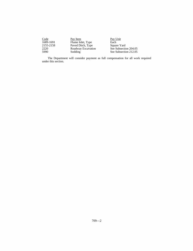
709—2
Code Pay Item Pay Unit1689-1691 Flume Inlet, Type Each2155-2158 Paved Ditch, Type Square Yard2220 Roadway Excavation See Subsection 204.055990 Sodding See Subsection 212.05
The Department will consider payment as full compensation for all work requiredunder this section.
710—1
SECTION 710 SMALL DRAINAGE STRUCTURES
710.01 DESCRIPTION. Construct, reconstruct, or adjust inlets, outlets, manholes,junction boxes, catch basins, edge drain outlet headwalls, and other small drainagestructures.
710.02 MATERIALS.
710.02.01 Concrete. Conform to Subsection 601.02.
710.02.02 Steel Reinforcement. Conform to Subsection 811.
710.02.03 Manhole Pipe. Conform to Section 810.
710.02.04 Brick Unit Masonry. Conform to Section 824.
710.02.05 Preformed Joint Filler. Conform to Section 807.
710.02.06 Dense Graded Aggregate. Conform to Section 805.
710.02.07 Pipe. Conform to Section 810.
710.02.08 Mortar. Conform to Section 601.02.
710.02.09 Structural Steel. Conform to Section 812.
710.02.10 Miscellaneous Metals. Conform to Section 813.
710.02.11 Steel Manhole Risers. Conform to Section 813.
710.02.12 Manhole Covers and Lids. Conform to Section 813.
710.02.13 Precast Manhole Sections. Conform to Section 824.
710.02.14 Manhole Steps. Provide manhole steps that are on the Department’s Listof Approved Materials.
710.02.15 Plastic Adjusting Rings. Provide plastic adjusting rings that are on theDepartment’s List of Approved Materials.
710.03 CONSTRUCTION
710.03.01 Newly Constructed Small Drainage Structures.
A) General. Construct all small drainage structures according to the Contract or asthe Engineer establishes. The Engineer may approve similar units that conformto the typical features depicted in the Standard Drawings. Construct smalldrainage structures using Class A concrete according to Subsection 601.03.
Attach all cast iron grates and lids and all structural steel grates to theframes, or to the concrete in the event there is no frame, with a chain of sufficientlength to permit removal for clean out and maintenance purposes. Obtain theEngineer’s approval, in writing, of shop drawings for the security device, whendifferent from what the Plans specify.
When extending pipe through the walls of small drainage structures, usepipe that is the same size and type, and conforms to the same requirements as theexisting pipe with which it is to be connected. Use extensions of sufficient length
710—2
to provide for connections and construction to prevent leakage of the pipe andstructure wall joint.
When excavation for small drainage structures extends under pavement,curb, gutter, or sidewalk, backfill the excavation with dense graded aggregate orgravel base. For backfill under aprons around drop box inlets or similarstructures, use dense graded aggregate or gravel base when required by theStandard Drawings. Use dense graded aggregate or gravel base backfill as theEngineer directs, and compact it in layers not exceeding 6 inches loose thickness.
When structures abut rigid pavement, place 1/2 inch preformed joint fillerbetween the rigid pavement and the structure for the full depth of the pavement.
Construct concentric or eccentric concrete pipe cones for manholesaccording to the Standard Drawings. Use precast concrete, precast concrete pipesections, and cast-in-place concrete, for manhole construction according to theStandard Drawings. Use precast concrete, precast concrete pipe sections, cast-in-place, brick, or plastic adjusting rings or for adjustment of existing manholesaccording to the Standard Specifications.
The Department will allow the use of square outside cast-in-place bases inlieu of round bases.
Form and construct a U-shaped channel in the base of circular pipemanholes with Class A concrete for a smooth continuation of the pipe. Do notallow the channel height to be less than 3/4 of the diameter of the smaller pipethat is intercepted.
Construct the tops of box inlets specified in the Standard Drawings to thesame cross slope as any existing or proposed shoulder, sidewalks, medians, orislands that will abut the box inlets.
Install steps according to the Standard Drawings in all manholes 4 feet orgreater in depth.
Do not paint frames, grates, and lids made of structural steel or cast iron forany of the structures.
B) Precast Structures Except Manholes. If furnishing precast structures, conformto the following requirements.
Only furnish products manufactured by a precast producer listed in theDepartment’s List of Approved Materials. If the producer does not have anapproved drawing for the product, submit 5 copies of shop drawings to theEngineer for review and approval. Ensure that the shop drawings show details ofany variation from the Department’s Standard Drawings and include any specialinstallation instructions necessary. Submit specifications for any specialmaterials for joint construction with the shop drawings, and submit samples ofjoint materials when requested.
Before beginning fabrication, furnish copies of the approved shop drawingsto the Engineer.
Use concrete that equals or exceeds the requirements for Class A concrete.Conform to Section 605 for the fabrication of the structures, the requirements fora mix design, and a Certified Concrete Technician.
Set the precast structures on a foundation of at least 4 inches of dense gradedaggregate compacted using mechanical tampers. Backfill box inlets withcantilevered portions to the elevation of the bottom of the cantilevered element,and place 4 inches of compacted dense graded aggregate before placing thecantilevered element.
Make positive seals between the pipe and the precast structure, and betweenindividual precast segments of the structure, in the field. Obtain any specialmaterials required for joint construction from the structure fabricator at noadditional expense to the Department.
The Department will sample and test all materials used in manufacture ofthe precast elements, including cement, aggregates, water, admixtures, steelreinforcement, and galvanized metal items according to the Department’sstandard procedures for these items. Do not begin fabrication until the
710—3
Department has approved these materials.Repair or replace structures damaged during handling, transporting,
erecting, or backfilling, or any structure that cannot be placed satisfactorily, asthe Engineer directs or approves.
710.03.02 Reconstructed Small Drainage Structures. Reconstruct existing unitsto the required line and elevation according to the Standard Drawings. Reconditionstructures where work is in excess of the limits required for adjusting small drainagestructures.
710.03.03 Adjusted Small Drainage Structures. Adjust existing frames and coversor gratings to the proper elevation. Accomplish this by removing or adding cast-in-placeconcrete masonry, precast reinforced concrete masonry, brick masonry, or an adjustingring, for a vertical distance not to exceed one foot above or below the existing masonry,and replacing existing castings firmly and permanently in place. For plastic adjustingrings, install and seal according to the manufacturer’s recommendations.
When the Contract specifies, use the Adjusting Ring Method as described in thissection, for adjusting manhole castings to grade. When applicable, use the Adjusting RingMethod in lieu of the methods outlined in the preceding paragraph. Raise a casting byinserting an additional casting into the existing frame as follows:
1) Use an adjusting casting of an approved type. Hold it rigidly to the existingframe using set screws in the bearing leg of the ring, or spot weld the adjustingring to the existing frame in 4 equally spaced locations.
2) Adjust existing manhole covers to the proper elevation by inserting variableheight adjustable casting that the Engineer approves into the existing frame. Usean adjustable casting capable of diameter adjustment as well as vertical heightadjustment.
When the difference between the existing elevation and the proposedelevation is less than the outer thickness of the cover or grate plus 1/2 inch, inserta casting that provides for receiving a new casting that is 2 inches less indiameter in any horizontal measurement than the existing casting. Furnish a newcover or grate similar in design to the existing cover or grate, except for thediameter or other horizontal dimensions.
3) Use a steel expanding manhole riser that is of the correct height and is designedto receive the existing manhole cover.
710.04 MEASUREMENT.
710.04.01 Newly Constructed Small Drainage Structures Except Type 12 DropBox Inlets. The Department will measure the quantity by each individual unit. TheDepartment will not measure any increase in the height of a structure to one foot from thePlan height for payment and will consider it incidental to this item of work. TheDepartment will measure for payment a change in height that exceeds one foot. TheDepartment will measure the quantity of reinforcing steel and concrete placed in excess ofthe plan height plus one foot according to Subsections 602.04 and 601.04, respectively.The Department will not measure excavation or materials for backfill for payment and willconsider them incidental to this item of work. The Department will not measure extrawork or materials required for use of precast units and will consider them incidental to thisitem of work.
710.04.02 Type 12 Drop Box Inlets. The Department will measure the quantity byeach individual unit according to Subsection 710.04.01, except the Department willmeasure the units in linear feet.
710.04.03 Reconstructed Small Drainage Structures. The Department willmeasure the quantity by each individual unit.
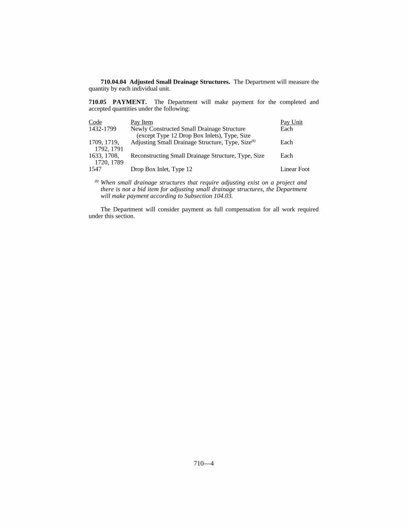
710—4
710.04.04 Adjusted Small Drainage Structures. The Department will measure thequantity by each individual unit.
710.05 PAYMENT. The Department will make payment for the completed andaccepted quantities under the following:
Code Pay Item Pay Unit1432-1799 Newly Constructed Small Drainage Structure Each
(except Type 12 Drop Box Inlets), Type, Size1709, 1719, Adjusting Small Drainage Structure, Type, Size(1) Each
1792, 17911633, 1708, Reconstructing Small Drainage Structure, Type, Size Each
1720, 1789 1547 Drop Box Inlet, Type 12 Linear Foot
(1) When small drainage structures that require adjusting exist on a project andthere is not a bid item for adjusting small drainage structures, the Departmentwill make payment according to Subsection 104.03.
The Department will consider payment as full compensation for all work requiredunder this section.

711—1
SECTION 711 PREFABRICATED VERTICAL WICKDRAINS
711.01 DESCRIPTION. Furnish and place prefabricated vertical wick drains at thelocations shown on the Plans.
711.02 MATERIALS. Use prefabricated wick drains that are included in theDepartment’s List of Approved Materials.
711.03 CONSTRUCTION. Stake the proposed location of the drains beforeinstallation. Do not vary the locations by more than 6 inches from those shown on thePlans. Maintain staked locations during construction. Install trial drains at locationswithin the work area. Demonstrate that all equipment and materials produce a satisfactoryinstallation. Obtain approval from the Engineer that materials and installation proceduresare satisfactory. Perform corrective action if trial drains are not accepted.
Install the prefabricated wick drains with a protective mandrel or sleeve. Provide ananchor plate or similar arrangement at the bottom to prevent soil from entering the bottomof the mandrel during installation of the drain and to anchor the drain tip at the requireddepth. Advance the mandrel or sleeve by continuously pushing or vibrating into the soiland retract after each installation. The maximum cross sectional area of the mandrel orsleeve is 14 square inches, including the attached anchor. Pre-auger when mandrel orsleeve cannot be continuously pushed or vibrated and when the Engineer deems necessary.Use augers with a maximum outside diameter of 8 inches. Install the prefabricated wickdrains vertically from the top of the working platform to the elevation shown on the plans.Ensure that plumbness of the drain does not deviate from the vertical more than 2 1/2inches in 10 feet. Provide the Engineer a means to verify plumbness of the equipment andthe depth of the drain.
Splice, no less than 6 inches, or connect the drain material according to themanufacturer’s recommendations to ensure continuity of flow. Limit splices to one perdrain. Cut the drain flush with the upper surface of the working platform. Install thedrains in a sequence that prevents travel over previously installed drains.
Repair or replace drains that are more than 6 inches from the plan locations,improperly installed, or damaged during construction at no cost to the Department.Remove any auger cuttings or debris from the top of the working platform beforecontinuing with fabric and fill placement over drains.
711.04 MEASUREMENT. The Department will measure prefabricated vertical wickdrains in linear feet. The Department will not measure trial drains or pre-augering forpayment and will consider it incidental Prefabricated Vertical Wick Drains.
711.05 PAYMENT. The Department will make payment for the completed andaccepted quantities under the following:
Code Pay Item Pay Unit2774 Prefabricated Wick Drain Linear Foot
The Department will consider payment as full compensation for all work requiredunder this section.
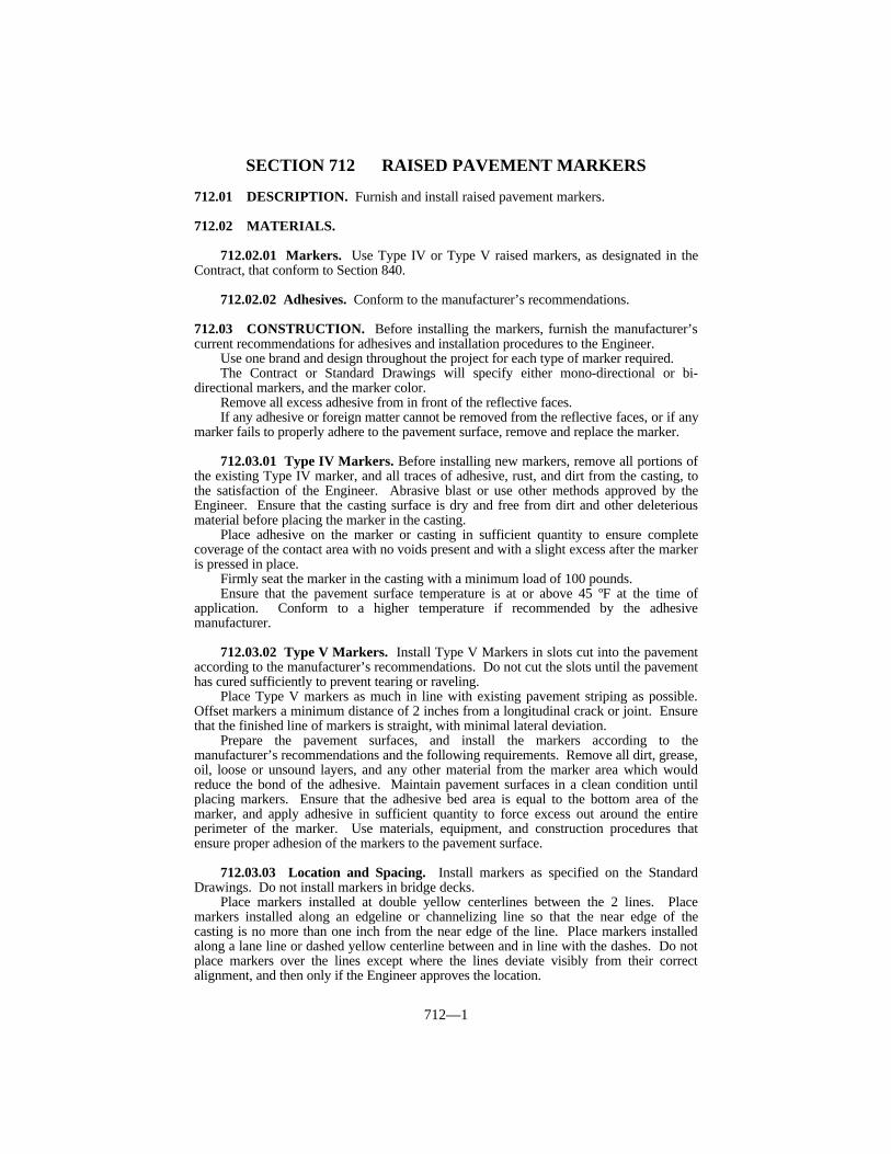
712—1
SECTION 712 RAISED PAVEMENT MARKERS
712.01 DESCRIPTION. Furnish and install raised pavement markers.
712.02 MATERIALS.
712.02.01 Markers. Use Type IV or Type V raised markers, as designated in theContract, that conform to Section 840.
712.02.02 Adhesives. Conform to the manufacturer’s recommendations.
712.03 CONSTRUCTION. Before installing the markers, furnish the manufacturer’scurrent recommendations for adhesives and installation procedures to the Engineer.
Use one brand and design throughout the project for each type of marker required.The Contract or Standard Drawings will specify either mono-directional or bi-
directional markers, and the marker color.Remove all excess adhesive from in front of the reflective faces.If any adhesive or foreign matter cannot be removed from the reflective faces, or if any
marker fails to properly adhere to the pavement surface, remove and replace the marker.
712.03.01 Type IV Markers. Before installing new markers, remove all portions ofthe existing Type IV marker, and all traces of adhesive, rust, and dirt from the casting, tothe satisfaction of the Engineer. Abrasive blast or use other methods approved by theEngineer. Ensure that the casting surface is dry and free from dirt and other deleteriousmaterial before placing the marker in the casting.
Place adhesive on the marker or casting in sufficient quantity to ensure completecoverage of the contact area with no voids present and with a slight excess after the markeris pressed in place.
Firmly seat the marker in the casting with a minimum load of 100 pounds.Ensure that the pavement surface temperature is at or above 45 ºF at the time of
application. Conform to a higher temperature if recommended by the adhesivemanufacturer.
712.03.02 Type V Markers. Install Type V Markers in slots cut into the pavementaccording to the manufacturer’s recommendations. Do not cut the slots until the pavementhas cured sufficiently to prevent tearing or raveling.
Place Type V markers as much in line with existing pavement striping as possible.Offset markers a minimum distance of 2 inches from a longitudinal crack or joint. Ensurethat the finished line of markers is straight, with minimal lateral deviation.
Prepare the pavement surfaces, and install the markers according to themanufacturer’s recommendations and the following requirements. Remove all dirt, grease,oil, loose or unsound layers, and any other material from the marker area which wouldreduce the bond of the adhesive. Maintain pavement surfaces in a clean condition untilplacing markers. Ensure that the adhesive bed area is equal to the bottom area of themarker, and apply adhesive in sufficient quantity to force excess out around the entireperimeter of the marker. Use materials, equipment, and construction procedures thatensure proper adhesion of the markers to the pavement surface.
712.03.03 Location and Spacing. Install markers as specified on the StandardDrawings. Do not install markers in bridge decks.
Place markers installed at double yellow centerlines between the 2 lines. Placemarkers installed along an edgeline or channelizing line so that the near edge of thecasting is no more than one inch from the near edge of the line. Place markers installedalong a lane line or dashed yellow centerline between and in line with the dashes. Do notplace markers over the lines except where the lines deviate visibly from their correctalignment, and then only if the Engineer approves the location.
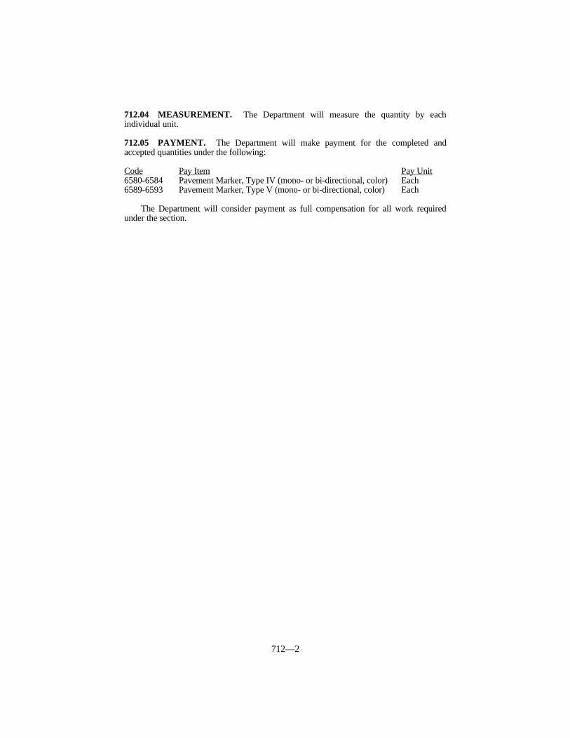
712—2
712.04 MEASUREMENT. The Department will measure the quantity by eachindividual unit.
712.05 PAYMENT. The Department will make payment for the completed andaccepted quantities under the following:
Code Pay Item Pay Unit6580-6584 Pavement Marker, Type IV (mono- or bi-directional, color) Each6589-6593 Pavement Marker, Type V (mono- or bi-directional, color) Each
The Department will consider payment as full compensation for all work requiredunder the section.

713—1
SECTION 713 PERMANENT PAVEMENT STRIPING
713.01 DESCRIPTION. Furnish and apply striping paint to provide lane lines,edgelines, and gore markings as specified in the Contract.
713.02 MATERIALS AND EQUIPMENT.
713.02.01 Paint. Conform to Section 842.
713.02.02 Drop On Glass Beads. Use beads that will ensure the pavement markingmaterial will meet retroreflectivity requirements. The Department will evaluate the beadsas part of the marking system through retroreflectivity readings.
713.02.03 Application Equipment. Use a self-propelled striper capable of heatingthe paint to provide uniform flow and enhance quick drying of the paint. Ensure that thestriper has a guide boom or optical pointer to attain smooth and straight lines. Ensure thatthe equipment maintains proper paint pressure at all times. Provide equipment capable ofapplying a single line or parallel lines of the specified width and in any combination of askip line and a solid line in one pass.
Provide equipment with a paint cutoff device to provide clean, square marking ends ofthe paint lines.
Equip the paint pots or tanks with an agitator that will keep the paint thoroughlymixed.
Provide equipment with bead dispensers, one for each paint spray gun, placed suchthat the beads are applied to the paint almost instantly as the paint is being placed on theroadway surface. Design and align the bead dispensers so that beads are applied under airpressure uniformly to the entire surface of the paint lines. Equip the bead dispensers withcutoff controls synchronized with the cutoff controls for the paint spray guns.
713.03 CONSTRUCTION. Provide yellow centerline markings, which are defined asthose separating traffic moving in opposite directions. Provide white lane line markings,which are defined as those separating traffic moving in the same direction. Ensure thatthese markings are skip lines and solid lines as required by Part 3 of the MUTCD. Ensurethat edge lines are solid lines, and determine the color from Part 3 of the MUTCD.
On interstates and parkways, and roadways with pre-existing 6-inch wide striping,install pavement striping that is 6 inches in width. On other routes, install pavementstriping that is 4 inches in width. Ensure that all lines have clean edges with a widthtolerance of plus 1/2 inch. The Engineer may waive the tolerances when deviations arecaused by undulation in the pavement surface.
Construct skip lines with a stripe-to-gap ratio of a 10-foot paint stripe to a 30-footgap. Ensure that the length of the stripe is between 10 and 10 1/2 feet. Ensure that thestripe-gap cycle is between 40 and 40 1/2 feet.
Apply striping before sunset on new pavement that is to be driven over by the public.When rain or other unavoidable occurrences prevent marking before sunset, mark thepavement during daylight hours as soon as conditions permit.
713.03.01 Records. On resurfacing, pavement restoration, and pavementrehabilitation projects, prepare and keep a written record of the locations of existingpavement markings, and furnish a copy to the Engineer before removing or obliterating themarkings.
713.03.02 Pavement Surface Preparation. Clean grease, oil, mud, dust, dirt,grass, loose gravel, or other deleterious material from the surface where pavementmarkings are to be applied. Use only Engineer approved cleaning methods.
713.03.03 Paint Application. On resurfacing, pavement restoration, and pavement

713—2
rehabilitation projects, put back the recorded existing pavement markings as modified bythe Engineer. On new construction, place the markings as the Contract specifies or as theEngineer designates.
Apply paint at a rate of not less than 16.5 gallons per mile of solid 4-inch line and24.8 gallons per mile of solid 6-inch line. Apply glass beads at a rate of not less than 6pounds per gallon.
713.03.04 Marking Removal. Remove all markings made in error or notconforming to the traffic operation in use. Remove markings by either an abrasion orburning process to the satisfaction of the Engineer. Do not paint with asphalt binder orother material to obliterate the markings.
713.03.05 Proving Period. A proving period will follow the application of thepermanent pavement striping. During this period, the Engineer will make suchobservations as are necessary to determine if the markings are acceptable. The provingperiod begins when the facility is opened to traffic.
A) Requirements. The minimum retroreflectivity requirements at the end of theproving period, as measured with a LTL 2000 or a mobile retroreflectometer (30M geometry), are as follows:
White: 175 mcd/lux/square meterYellow: 150 mcd/lux/square meter
The Department will take these measurements between 30 and 60 days afterthe start of the proving period, with acceptance based on KM 202 for LTL 2000readings and KM 203 for mobile readings. If the Department determines that themarkings are acceptable, the installation of the markings will be consideredcomplete.
B) Failure. For any one-mile section and each gore area during the proving period,the Department will consider the section defective when the retroreflectivity fallsbelow the minimum required. The Department will consider each edge line,centerline, lane line and gore area marking separately.
C) Corrective Work. If a line is found to be defective, repair or remove andreplace the line. Perform pavement marking replacement according to therequirements specified in this subsection for the initial application. Thecorrective work will be subject to a proving period as listed above.
713.03.06 Acceptance of Non-Specification Markings. If weather conditionsallow, perform corrective work to bring striping retroreflectivity into conformance. Ifcorrective work has been performed and the work meets all requirements except forminimum retroreflectivity, the Department may accept the work according to Subsection105.04. When the Engineer determines that the markings may be left in place, theDepartment will accept them at a reduction in the Contract unit bid price according to theAcceptance Pay Schedule. Additionally, the Engineer may remove the striping crew forthe remainder of the project according to Subsection 108.06 Part A).
The Engineer may also apply this section when corrective work cannot be performeddue to weather.
Acceptance Pay Schedule – White156 to 174 mcd/lux/square meter – 50% pay138 to 155 mcd/lux/square meter – 25% pay120 to 137 mcd/lux/square meter – 0% pay< 120 mcd/lux/square meter – unacceptable
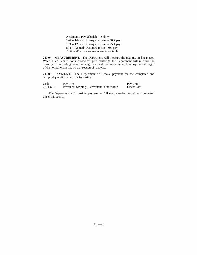
713—3
Acceptance Pay Schedule – Yellow126 to 149 mcd/lux/square meter – 50% pay103 to 125 mcd/lux/square meter – 25% pay80 to 102 mcd/lux/square meter – 0% pay< 80 mcd/lux/square meter – unacceptable
713.04 MEASUREMENT. The Department will measure the quantity in linear feet.When a bid item is not included for gore markings, the Department will measure thequantity by converting the actual length and width of line installed to an equivalent lengthof the normal width line on that section of roadway.
713.05 PAYMENT. The Department will make payment for the completed andaccepted quantities under the following:
Code Pay Item Pay Unit6514-6517 Pavement Striping - Permanent Paint, Width Linear Foot
The Department will consider payment as full compensation for all work requiredunder this section.
714—1
SECTION 714 DURABLE PAVEMENT STRIPING
714.01 DESCRIPTION. Furnish and install durable marking materials, thermoplasticor Type I tape, to provide lane lines, edgelines, and gore markings as specified in theContract.
714.02 MATERIALS AND EQUIPMENT.
714.02.01 Thermoplastic. Conform to Section 837.
714.02.02 Type I Tape. Conform to Section 836.
714.02.03 Binder. Furnish a binder that the manufacturer of the pavement markingmaterial recommends and the Engineer approves. Provide a binder that forms acontinuous film that dries rapidly and adheres to the pavement. Provide a material thatdoes not discolor or cause any noticeable change in the appearance of the pavement outsideof the finished pavement marking. Submit the material and method of application to theEngineer and obtain written approval from the Engineer and the manufacturer of thepavement marking material before applying.
714.02.04 Drop On Glass Beads. Use beads that will ensure the pavement markingmaterial will meet retroreflectivity requirements. The Department will evaluate the beadsas part of the marking system through retroreflectivity readings.
714.02.05 Thermoplastic Application Equipment. Provide equipment with anextrusion die that simultaneously deposits and shapes lines at a minimum thickness of 90mils on the pavement surface. Do not use spray and ribbon gun applicators.
Ensure the application equipment conforms to the following:
1) Capable of providing continuous and uniform heat to maintain the materialbetween 400 and 440 °F throughout the mixing, conveying, and dispensing.
2) The kettle is capable of continuous agitation during mixing and heated storageand is equipped with an automatic thermostat control device and materialthermometer.
3) Motorized and capable of applying a uniform line at a rate of 3 mph.4) Equipped with a cutoff device that provides clean, square stripe ends.5) Equipped with an automatic bead dispenser.
714.03 CONSTRUCTION. Provide yellow centerline markings, which are defined asthose separating traffic moving in opposite directions. Provide white lane line markings,which are defined as those separating traffic moving in the same direction. Ensure thatthese markings are skip lines and solid lines as required by Part 3 of the MUTCD. Ensurethat edge lines are solid lines, and determine the color from Part 3 of the MUTCD.
Install pavement striping at the width specified in the Contract. Ensure that all lineshave clean edges with a width tolerance of plus 1/2 inch. The Engineer may waive thetolerances when deviations are caused by undulation in the pavement surface.
Construct skip lines with a stripe-to-gap ratio of a 10-foot stripe to a 30-foot gap.Ensure that the length of the stripe is between 10 and 10.5 feet. Ensure that the stripe-gapcycle is between 40 and 40.5 feet.
714.03.01 Layout. Install all pavement markings according to Part 3 of the MUTCDand the following requirements.
Make the width of lane lines and edgelines as specified in the Plans or as theEngineer directs. Make lines for gore area markings twice the normal width line for thatsection of roadway.
714—2
Unless striping plans are included in the proposal or otherwise directed by theEngineer, install gore area markings as shown in Figures 3B-8 and 3B-9 of the MUTCD.Do not use the optional markings shown (transverse lines in the neutral area and dottedextension of the right edgeline).
Due to the possibility that water may be retained on the roadway by the thermoplasticedgelines, place a one foot gap every 20 feet in all thermoplastic edgelines. Do not installgaps for taped edgelines.
Offset longitudinal lines at least 2 inches from longitudinal pavement constructionjoints. Offset longitudinal lane lines on multi-lane highways 2 inches towards the median.
On resurfacing, pavement restoration, and pavement rehabilitation projects, prepareand keep a written record of the locations of existing pavement markings, and furnish acopy to the Engineer before removing or obliterating the markings. The Engineer willnotify you of any changes to the existing markings.
Before applying the pavement marking material, pre-mark the pavement surface andobtain the Engineer’s approval of the proposed location, alignment, and control guides.
714.03.02 Surface Preparation.
1) Remove existing pavement markings and clean grease, oil, mud, dust, dirt, grass,loose gravel, or other deleterious material from the surface where pavementmarkings are to be applied, as directed by, and by methods acceptable to, theEngineer.
2) Remove the existing pavement markings until a minimum of 90 percent of thepavement surface is uniformly exposed throughout. Ensure that the pavementsurface is in proper condition for successful bonding of the pavement markingsand provides a neat appearance. Do not leave any loose or flaking existingpavement markings.
3) When removing the existing pavement markings, ensure that the finishedpavement surface is not damaged or left in a condition that may mislead ormisdirect the motorist. Repair any damage to the pavement, pavement jointmaterials, or the pavement surface caused by the removal of the existingpavement markings in a manner acceptable to the Engineer. After completingthese operations, use compressed air to blow clean the pavement surface ofresidue and debris resulting from the removal of existing pavement markings.
4) When removal of existing pavement markings and objectionable materialsobscures existing pavement markings of a lane occupied by public traffic,immediately remove the residue, including dust, from the surface being treated.Obtain the Engineer’s approval of the removal methods.
5) Place the final pavement markings on the same day that the existing pavementmarkings are removed.
6) On concrete surfaces and as the Engineer directs on older asphalt pavements,apply binder to the area where placing pavement marking material.
7) On new concrete pavement surfaces, remove the curing compound from thepavement surface before applying the binder and the pavement marking material.
714.03.03 Application.
A) Type I Tape. Apply according to the manufacturer’s recommendations. Whenapplied to concrete, cut the tape at all joints.
B) Thermoplastic. Rather than installing thermoplastic pavement markings onfresh asphalt, the Department will allow temporary striping with paint. Whenchoosing this option, cover the temporary striping with the thermoplasticpavement markings within 30 calendar days. The Department will not requireremoval of the interim pavement marking paint before applying the thermoplasticpavement markings.
Install the thermoplastic material at a minimum thickness of 90 mils on thepavement surface in a melted state at a temperature from 400 and 440 °F.

714—3
Apply additional glass beads by drop-on or pressure spray methods insufficient quantities to obtain the retroreflectivity requirements specified inSubsection 714.03.06.
Verify the adhesion of the thermoplastic to asphalt pavements by performingbond checks, at least 4 per mile of line, as follows. Approximately 60 to 120seconds after applying a thermoplastic line to the roadway surface, cut and liftapproximately a 6-inch section of thermoplastic. The thermoplastic issuccessfully bonding to the pavement surface if a layer of asphalt clings to theremoved thermoplastic stripe and the pavement surface under the removed stripeis shiny and black.
Provide finished markings that are continuous and uniform in shape, havingclear and sharp dimensions. Ensure that all lines have well-defined edges.
714.03.04 Restrictions. Do not apply the pavement marking material when air andpavement temperatures are below 50 °F.
Do not apply the pavement marking material when the surface of the pavementcontains evidence of moisture in amounts significant enough to prevent the pavementmarking material from bonding to the pavement. Significant amounts of moisture can becaused by heavy dew or very humid nights as well as from rainfall.
If encountering significant amounts of moisture while applying the thermoplastic, theContractor, at his own risk, may attempt to apply thermoplastic subject to the followingrestrictions. Heat the thermoplastic material to the upper temperature limit specified by themanufacturer, and apply a test line on the pavement. Perform a bond check according toSubsection 714.03.03. If the thermoplastic successfully bonds to the pavement continue toapply thermoplastic lines, provided there is evidence that the moisture is escaping throughthe surface of the line, as indicated by very small pin holes. If there is excessive moisture,as indicated by larger sized holes or bubbles on the surface of the line, do not applythermoplastic until the moisture can be effectively dealt with. Perform a sufficient numberof bond checks to ensure that the thermoplastic is bonding to the pavement.
714.03.05 Project Conflicts. When other construction projects are in progresswithin the limits of the designated work areas, install no pavement markings that will beremoved or damaged by immediate subsequent construction. The Engineer will givenotification of all conflicting construction projects. Schedule the installation of pavementmarkings after completion of the conflicting construction. When scheduling is impossibleor creates an undue hardship, the Engineer will delete the intersection from this project.
714.03.06 Proving Period for Durable Markings. A 180 day proving period willfollow the application of the durable markings. During this period, the Engineer willmake such observations as are necessary to determine if the markings are acceptable. Theproving period begins when the facility is opened to traffic.
A) Requirements.
1) Type I Tape. During the proving period, ensure that the pavement markingmaterial shows no signs of failure due to blistering, excessive cracking,bleeding, staining, discoloration, oil content of the pavement materials,deterioration due to contact with grease deposits, oil, diesel fuel, or gasolinedrippings, chipping, spalling, poor adhesion to the pavement, loss ofretroreflectivity, vehicular damage, and normal wear. Type I Tape ismanufactured off site and warranted by the manufacturer to meet certainretroreflective requirements. As long as the material is adequately bonded tothe surface and shows no sign of failure due to the other items listed inSubsection 714.03.06 A) 1), retroreflectivity readings will not be required.In the absence of readings, the Department will accept tape based on anighttime visual observation.
714—4
2) Thermoplastic. During the proving period, ensure that the thermoplasticpavement marking material shows no signs of failure due to blistering,excessive cracking, bleeding, staining, discoloration, oil content of thepavement materials, smearing or spreading under heat, deterioration due tocontact with grease deposits, oil, diesel fuel, or gasoline drippings, chipping,spalling, poor adhesion to the pavement materials, loss of retroreflectivity,vehicular damage and normal wear.
The minimum retroreflectivity requirements at the end of the provingperiod, as measured with a LTL 2000, LTL 2000Y, or Department approved30M geometry mobile instrument are as follows:
White: 300 mcd/lux/square meterYellow: 175 mcd/lux/square meter
The Department will take these measurements between 150 and 210days after the start of the proving period, basing acceptance on KM 202 forLTL 2000 readings and KM 203 for mobile readings. If the Departmentdetermines that the markings are acceptable, the installation of the markingswill be considered complete.
B) Failure. For any one mile section and each gore area during the proving period,the Department will consider the section defective when the retroreflectivity fallsbelow the minimum required or more than 10 percent of the material fails to meetthe other requirements of A) above. The Department will consider each edgeline, centerline, lane line and gore area marking separately.
C) Corrective Work. If a line is found to be defective, repair or remove andreplace the line. Perform pavement marking replacement according to therequirements specified in this subsection for the initial application. Thecorrective work will be subject to a proving period as listed above.
714.03.07 Marking Removal. Remove all markings made in error or notconforming to the traffic operation in use. Remove markings by either an abrasion orburning process to the satisfaction of the Engineer. Do not paint with asphalt binder orother material to obliterate the markings.
714.03.08 Acceptance of Non-Specification Thermoplastic Markings. Whenreasonably acceptable work has been produced but retroreflectivity requirements are notmet, the Department may accept the work according to Subsection 105.04. When theEngineer determines that the markings may be left in place, the Department will acceptthem at a reduction in the Contract unit bid price according to Acceptance Pay Schedulefor Thermoplastic.
714.04 MEASUREMENT. When a bid item is not included for gore markings, theDepartment will measure the quantity by converting the actual length and width of lineinstalled to an equivalent length of the normal width line on that section of roadway.
714.04.01 Thermoplastic Pavement Markings. The Department will measure forpayment by the units listed in the Quantity Summary. The Department will not measuresampling, testing, surface preparation, pre-marking, interim marking, and binderapplication for payment and will consider them incidental to the thermoplastic bid items.The Department will not measure corrective work for payment.
714.04.02 Durable Pavement Markings, Type I. The Department will measure forpayment by the units listed in the Quantity Summary. The Department will not measuresampling, testing, surface preparation, pre-marking, and binder application for paymentand will consider them incidental to the pavement marking bid items. Corrective workwill not be measured for payment.

714—5
714.04.03 Pavement Striping Removal. When listed as a bid item, the Departmentwill measure for payment by the units listed in the Quantity Summary. The Departmentwill not measure for payment the removal of existing pavement markings that have notbeen authorized by the Engineer. When the Contract does not list a bid item, theDepartment will consider existing pavement marking removal incidental to the otherpavement marking bid items. The Department will not measure for payment anycorrective work required due to the removal work.
714.05 PAYMENT. The Department will make payment upon completion of the work.If after the proving period the markings do not meet minimum retroreflectivityrequirements, the Department will adjust the payment or require corrective work accordingto the following:
Code Pay Item Pay Unit6540-6547 Pavement Striping - Thermoplastic, width, color Linear Foot6554-6561 Pavement Striping - Durable Type I Tape, width, color Linear Foot
The Department will consider payment as full compensation for all work requiredunder this section.
ACCEPTANCE PAY SCHEDULE FOR THERMOPLASTICPay Value White Yellow
mcd/lux/square meter mcd/lux/square meter1.00 300 1750.50 200-299 100-174
Remove and Replace < 200 < 100
715—1
SECTION 715 PANEL TRAFFIC SIGNS
715.01 DESCRIPTION. Furnish and install extruded panel traffic signs. Traffic signsinclude ground mounted, overhead structure mounted, or bridge mounted signs.
715.02 MATERIALS.
715.02.01 Panel Signs. Conform to Section 833.
715.02.02 Concrete. Conform to Subsection 601.02 and 601.03.
715.02.03 Steel Reinforcement. Conform to Section 602.
715.02.04 Structural Steel. Conform to Section 812.
715.02.05 Miscellaneous Metals. Conform to Section 813.
715.02.06 Retroreflective Materials. Conform to Section 830.
715.02.07 “Pop” Fasteners. Use corrosion resistant protruding head “pop” rivetswith a minimum diameter of 1/8 inch. Obtain the Engineer’s approval before use.
715.03 CONSTRUCTION. The Department may inspect fabrication and erectionwork. The Department will perform a day and night inspection after the installation iscomplete.
If a manufacturer provides a warranty on any materials covered under thesespecifications, furnish the same warranty to the State. Perform the work according to therequirements specified in the following publications:
• MUTCD• AASHTO Specifications for Design and Construction of Structural Supports for
Highway Signs• Federal Standard 595, Standard Highway Sign Colors• Standard Highway Signs
Use Class A concrete according to Subsection 601.03.
715.03.01 Location. Use the Plans as general guidance for the extent and generalarrangement of signs. Consider sign locations specified in the Plans as approximate only.Determine the exact location for each sign and obtain the Engineer’s approval. When it isnecessary to relocate any sign more than 25 feet from the station listed, obtain the Divisionof Traffic’s approval. Center overhead signs over the lane or lanes to which they apply.Allow for differences in elevation across the full shoulder width, as specified in the Plans,in maintaining the required 18-foot minimum vertical clearance to the bottom of the lowestparts of the signs or supports for overhead signs. Submit all proposed revisions in writingto the Engineer for written approval.
715.03.02 Messages. Sign messages specified in the Plans are the final messages.Due to construction phasing, the Engineer may make changes in some messages. If theEngineer changes a message before the sign installation store the final message copy onthe project. Conform message spacing to the applicable requirements of the previouslycited publications for guide signs, and the manufacturer’s recommendations for sign sizesindicated, as the Engineer approves. Center message copy over the lane or lanes to whichthey apply.
715.03.03 Attachment. Attach letters, symbols, numbers, and borders to sign faces

715—2
with “pop” fasteners (“pop” rivets).
715.03.04 Shields. For panel sign mounted route markers, use a retroreflectorizedwhite cut-out for the US shield and KY round shape, omitting the black background of thestandard rectangular shapes. Do not use borders on the cut-out shapes. Use thedimensions shown in the Standard Highway Signs Manual. Space route markers evenlyacross the panel sign face.
715.03.05 Covering. Cover sign faces only when absolutely necessary and keepcovered only as long as necessary. Do not use tape, paper, plastic, or sheet metal covers.Replace any signs damaged as a result of being covered at no expense to the Department.
715.03.06 Shop Drawings. Submit 5 complete sets of detailed shop drawings to theEngineer for written approval before fabricating signs. Before installation, obtain theEngineer’s written approval of drawings, descriptions, manufacturer’s cuts, etc. coveringall materials to be used. Submit mill test reports for I-beams, wide flange beams,aluminum or steel panels, and each different gauge of aluminum or steel sheeting used tothe Engineer for approval before installation.
715.03.07 Fabrication. Hot dip galvanize all steel components after completingfabrication. Regalvanize or paint all abraded or damaged surfaces with 2 coats ofcommercially available zinc rich paint.
Ensure that sign structures are free from kinks, twists, or bends and are uniform inappearance. Assemble completed sections in the shop and check them for straightness,alignment, and dimensions. Correct any irregularities.
Consider sign post lengths as approximate only. Conform to the applicablerequirements contained in AWS for welded fabrication.
715.03.08 Footings, Bases, and Pedestals. Provide protection for traffic duringconstruction of concrete bases for overhead sign structures.
Exercise caution during any excavation to prevent damaging existing utilities whetherspecified or not specified in the Plans. Repair or replace any utilities that are disturbed ordamaged during construction at no additional expense to the Department. Provide theEngineer the opportunity to inspect repairs to damaged utilities before covering the repairs.
Construct footings and bases according to Subsection 601.03. The Department willallow construction of footings against undisturbed earth without forms, unless otherwisedirected. Slope top surfaces of bases and pedestals to provide for drainage. Provide anordinary surface finish for all exposed concrete. Construct a rustication groove in allpedestals. Cure concrete according to Subsection 601.03.17.
Remove beam sign supports concurrently with the relocation of affected signs to newsupports. Grade, to the existing slope, any areas disturbed by removing existing signs orconstructing new signs, and reseed as the Engineer directs.
715.03.09 Sign Beams and Supports. Use beams of sufficient length to extend fromthe top of the sign to the required base embedment. Use either Type A (standard beaminstallation) or Type B (break-away beam installation) as specified in the Plans. Embedbeams in concrete to a depth equal to the dimension “A” shown for each sign.
Wait 7 calendar days after placing concrete before mounting beams and supports tothe bases or pedestals. Where aluminum is in contact with concrete, thoroughly coat thecontacting surface with alumilastic compound or an approved equal in order to completelyinsulate the aluminum from the concrete. Where bond between the aluminum andconcrete is desired, coat the aluminum with commercially available zinc chromate paint,and allow it to dry before installation.
A) Type A Beam Alternates.
1) Alternate I. Furnish A 36 steel beams galvanized according to ASTM
715—3
A 123.2) Alternate II. Furnish 6061-T6 (ASTM B 221). When aluminum beam size
is not indicated, use Alternate I.
B) Type B Beam. Specifications for Type B beams are listed on the break-awaydetail sheet.
For break-away assemblies, assemble the posts to stub with bolts and withone flat washer on each bolt between plates. Use shims to plumb the posts.Then tighten bolts to the maximum possible by use of a 12 to 15-inch wrench inorder to bed washers and shims and to clean bolt threads. Then loosen all bolts,and in turn retighten them in a systematic order to the prescribed torque specifiedin the Plans.
715.03.10 Bridge Mounting for Signs. Do not install brackets for support of bridgemounted signs within 6 inches of open joints in concrete handrail plinths. The Departmentwill allow moving of supports to clear handrail posts. Place sign brackets on 4-footmaximum centers with a 2-foot maximum sign overhang.
When necessary, remove existing handrails to drill anchor bolt holes. Reinstallhandrails after drilling. Locate bolt holes drilled in prestressed concrete beams to notinterfere with steel strands. Drill holes for concrete beams with a rotary type core drill. Donot use impact type drills. Install bolts with expansion plugs and lock washers in the holesand fill the void between the plug and face of the concrete with non-shrinking grout.
715.03.11 Mounting Signs. Install new concrete bases, support beams, etc. beforedismantling any existing sign. When existing signs are to be out of service for more thanone work shift, install temporary signing of the proper color, shape, and with copy ofsimilar configuration to existing signs at the same approximate station as the out of servicesign. Install sign panels on sign structures, beams, or bridge mounted brackets asspecified in the Plans. Delay installation as long as possible to avoid any damage to thesign. Replace all damaged signs.
715.04 MEASUREMENT.
715.04.01 Concrete. The Department will measure according to Subsection 601.04.
715.04.02 Steel Reinforcement. The Department will measure according toSubsection 602.04.
715.04.03 Sign Supports. The Department will measure the quantity by eachindividual unit.
The Department will not measure clearing and grubbing, excavation, electricalconduit and ground rods located in support bases, and temporary panel signing forpayment and will consider them incidental to this item of work.
715.04.04 Beams. The Department will measure the quantity in pounds.
715.04.05 Bridge Mounted Sign Fixtures. The Department will measure thequantity by each individual unit. A unit is as all material necessary for mounting a bridgemounted sign of given size.
715.04.06 Sign Panels. The Department will measure the quantity in square feet foreach size and type.
715.05 PAYMENT. The Department will make payment for the completed andaccepted quantities under the following:
715—4
Code Pay Item Pay Unit6490 Class A Concrete for Signs See Subsection 601.056491 Steel Reinforcement for Signs See Subsection 602.056416-6426, 6436, 6438, Sign Supports, Size and Type Each
6443, 64456400, 6402, 6440 Sign Beams, Type Pound6448 Sign Bridge Attachment Bracket Each6405-6409 Sign Panels, Type and Size Square Foot
The Department will consider payment as full compensation for all work requiredunder this section.

716—1
SECTION 716 ROADWAY LIGHTING SYSTEMS
716.01 DESCRIPTION. Furnish, install, and connect roadway lighting systems, withaccessories according to the Contract.
716.02 MATERIALS.
716.02.01 Roadway Lighting Materials. Conform to Section 834. Obtain theEngineer’s approval for all materials before installation. Submit for material approval 7copies of descriptive literature, drawings, and any requested design data. Do not makesubstitutions for approved materials without written permission as described above.
716.02.02 Paint. Conform to Sections 821 and 834.
716.02.03 Concrete. Conform to Subsection 601.02 and 601.03.
716.03 CONSTRUCTION. Perform the work according to:
1) the Contract,2) National Electrical Code,3) AASHTO Standard Specifications for Structural Supports for Highway Signs,
Luminaires and Traffic Signals, 1994 edition,4) AASHTO Roadside Design Guide,5) AASHTO An Informational Guide for Roadway Lighting, 1984 edition,6) Manual on Uniform Traffic Control Devices for Streets and Highways, and7) the standards of the utility company servicing the installation.
Before ordering materials, confirm the type and location of the service available fromthe utility company.
After completing the installation and before the electrical service is connected, obtaina certificate of compliance from the Kentucky Department of Housing, Buildings andConstruction, Electrical Inspection Division.
The Plans indicate the extent and general arrangement of the lighting circuits andequipment and are for general guidance. Advise the Engineer in writing and obtainwritten approval for any necessary modifications.
Stake pole locations and obtain the Engineer’s approval. Use Class A concreteaccording to Subsection 601.03.
716.03.01 Wiring. Where installing more than one circuit within the same conduit,affix permanent circuit identification numbers to the wires wherever the wiring emerges,including junction boxes, transformer bases, and control cabinets.
716.03.02 Conduit Installation. Provide rigid steel conduit encasement for allconductors except as specified in the Plans. The Department will allow bonded slip jointsfor joining rigid conduit to junction boxes. When a standard coupling cannot be used, usean approved threaded union coupling. Ream all conduit ends to remove burrs and sharpedges. Paint damaged portions of galvanized surfaces and untreated threads resulting fromfield cuts with an Engineer approved rust prohibitive paint. Ensure that conduit bendshave a radius of not less than 12 times the nominal diameter of the conduit.
Lay conduit not subjected to traffic to a depth of no less than 18 inches. Lay ductedcables to a depth of 2 feet. On transverse crossings under roadway surfaces and shoulders,place the conduit at a depth of no less than 2 feet below grade. Likewise, run ductedcables inside rigid steel conduits, or other Engineer approved methods, when crossingroadways. Make all pavement crossings by placing conduit in the subgrade before pavingor by boring and jacking under existing pavements. When it is necessary to bore underroadways and ramps, obtain the Engineer’s approval of the boring procedure. Do not cut
716—2
any pavement without obtaining the Engineer’s prior approval. Before starting backfilling,allow the Engineer to inspect the conduit installation. Place and compact the backfillmaterials in lifts of 9 inches or less. Restore all disturbed areas as a result of theContractor’s operations to the Engineer’s satisfaction. Bond together conduits, junctionboxes, metal poles, and control boxes throughout the lighting system to all ground rods byusing grounding bushings on the conduit ends. Bond these conduits to the electricalsystem ground.
Install underground utility warning tape immediately above the circuit cables. Burythe tape at a depth of 6 to 10 inches. Use a durable and colorfast tape conforming with theAPWA-ULCC National Color Code with black lettering on red that continuously reads“CAUTION: ELECTRIC LINE BURIED BELOW” alternating with a no diggingsymbol.
716.03.03 Splicing. When the Engineer allows splicing, splice only in junctionboxes, in transformer bases, or in pole bases when no transformer base is provided. Makebutt splices, soldered and encased in waterproof resin filled splicing kits. Use copper ofthe correct wire range, 3M Scotchcast splicing kits or approved equal, and Scotchcast #4resin or approved equal. Encase each conductor, including the ground, in a separate splicekit. Make splices for connecting leads from multiple circuit conductors to ballastterminals with approved field applied connector kits.
716.03.04 Painting. Clean ungalvanized or damaged surfaces of exposed junctionboxes, pull boxes, control panels, poles, and similar equipment, and apply one coat of aninhibiting paint and two coats of aluminum paint, inside and out, after completinginstallation. For items fabricated from galvanized or nonferrous alloys, which areinherently rust resistant, paint only on damaged surfaces with an application of inorganiczinc rich primer or aluminum paint, as applicable.
716.03.05 Lighting Standard Installation. Ensure that concrete bases for lightingstandards, up to 50 feet high, have a minimum depth of 6 1/2 feet and a minimumdiameter of 2 feet. Construct a level base, with no more than a 3/8-inch gap existingbetween the concrete base and the transformer base when the pole is plumbed. TheDepartment will allow steel plates or washers between the nuts and the transformer baseor pole for stabilization and shims to plumb the pole for gaps up to 1/4 inch.
For breakaway supports, conform to Section 7 of the Standard Specifications forStructural Supports for Highway Signs, Luminaires, and Traffic Signals. Grade thesurrounding surface appropriately to meet the 4-inch breakaway support stub height.
716.03.06 Marker Installation. When specified in the Plans, mark the position ofburied circuits with concrete slab markers. Install cable markers immediately above thecable. Place the markers with the top exposed approximately 2 inches above ground.Mark each cable run at approximately 100-yard increments between junction boxes and/orlight poles, with additional markers at each change of direction. Install concrete slabmarkers at the end of the conduits crossing a roadway if a junction box is not present.
Impress the word “LIGHTING”, appropriate directional arrows, and appropriatecircuit identification number on each marking slab. Use letters that are approximately 3inches high and 2 inches wide. Ensure that the stroke is 1/2 inch wide and 1/4 inch deep.
716.03.07 Drawings. Before final inspection of the roadway lighting system,provide a complete set of reproducible as-built drawings that show the arrangement andlocations of all equipment and circuits. Include each duct or conduit pavement crossingwith distances to permanent markers, such as structures and curb lines. Keep a dailyrecord of all conduit placed in trenches, showing the distance from the pavement edge, thedepth, and the length of runs, and indicate these on the as-built drawings.
716.03.08 Testing. After completing the service and equipment installations,conduct an operating test. Demonstrate that the system operates according to the Contract.

716—3
Ensure that circuits test free of shorts and unauthorized grounds and have an insulatingresistance of no less than 10 megohms when tested with 500 volt direct current potential ina reasonably dry atmosphere between conductors and ground. The Department will alsoconduct its own tests with its own equipment before final acceptance.
716.04 MEASUREMENT.
716.04.01 Roadway Lighting Systems. The Department will measure the work inthe units specified in the Contract.
The Department will consider any costs associated with securing service and requiredcertificates and providing as-built drawings incidental to this item of work.
716.04.02 Trenching and Backfilling. The Department will measure the quantity inlinear feet.
716.05 PAYMENT. The Department will make payment for the completed andaccepted quantities under the following:
Code Pay Item Pay Unit---- Roadway Lighting, Contract Items Contract Units4820 Trenching and Backfilling Linear Foot
The Department will consider payment as full compensation for installing and placingthe complete roadway lighting systems in satisfactory operation.

717—1
SECTION 717 THERMOPLASTIC INTERSECTIONMARKINGS
717.01 DESCRIPTION. Furnish and install thermoplastic intersection markings (StopBars, Crosswalks, Turn Arrows, etc.) by either a machine applied, screed extrusionprocess or by applying preformed thermoplastic intersection marking material.
717.02 MATERIALS AND EQUIPMENT.
717.02.01 Preformed Thermoplastic Intersection Marking Material. Selectfrom the Department’s List of Approved Materials.
717.02.02 Extruded Thermoplastic Pavement Marking Material. Conform toSection 837.
717.02.03 Binder. Conform to Subsection 714.02.03
717.02.04 Drop On Glass Beads. Use beads that will ensure the pavement markingmaterial will meet retroreflectivity requirements. The Department will evaluate the beadsas part of the marking system through retroreflectivity readings.
717.02.05 Extruded Thermoplastic Application Equipment. Provide equipmentwith a shaping die that simultaneously deposits and shapes lines at a minimum thicknessof 90 mils on the pavement surface. Do not use spray and ribbon gun applicators.
Ensure the application equipment conforms to the following:
1) Capable of providing continuous and uniform heat to maintain the materialbetween 400 and 440 °F throughout the mixing, conveying, and dispensing.
2) The kettle is capable of continuous agitation during mixing and heated storageand is equipped with an automatic thermostat control device and materialthermometer.
3) Equipped with a cutoff device that provides clean, square stripe ends.4) Equipped with an automatic bead dispenser.
717.03 CONSTRUCTION.
717.03.01 Layout. On resurfacing, pavement restoration, and pavementrehabilitation projects, prepare and keep a written record of the locations of existingpavement markings, and furnish a copy to the Engineer before removing or obliterating themarkings. The Engineer will notify you of any changes to the existing markings.
On new construction, the Department will provide more detailed information for eachintersection prior to beginning work. This information will consist of plans, a drawing ofeach intersection, or an inspector to work with each crew to layout the markings in thefield.
Before applying the pavement marking material, pre-mark the pavement surface andobtain the Engineer’s approval of the proposed location, alignment, and control guides.
717.03.02 Surface Preparation. Clean all grease, oil, mud, dust, dirt, grass, loosegravel, or other deleterious material from the surface where pavement markings are to beapplied as directed by, and by methods acceptable to, the Engineer.
On concrete surfaces and as the Engineer directs on older asphalt pavements, applybinder to the area where placing pavement marking material. Ensure that all solvents haveevaporated from the binder before applying the marking material. On new concretepavement surfaces, remove the curing compound from the pavement surface beforeapplying the binder and the pavement marking material.
717—2
717.03.03 Application. Install extruded thermoplastic at a minimum thickness of 90mils on the pavement surface in a melted state at a temperature from 400 and 440 °F.Install preformed thermoplastic according to manufacturer's instructions at a minimumthickness of 125 mils. Apply additional glass beads by a drop-on method at a rate thatsatisfies the retroreflectivity requirements of Subsection 717.03.05.
When installing symbols and legends (turn arrows, the word “ONLY” etc.) by theextrusion process, ensure that the finished markings conform to the standard size andshape in the Manual on Uniform Traffic Control Devices.
Verify the adhesion of the thermoplastic to asphalt pavements by performing bondchecks as follows. Approximately 60 to 120 seconds after applying the thermoplasticmaterial cut and lift approximately a 6-inch section. The thermoplastic is successfullybonding to the pavement surface if a layer of asphalt clings to the removed thermoplasticand the pavement surface under the removed section is shiny and black.
Ensure that finished markings are continuous and uniform in shape having clear andsharp edges with uniform bead distribution across the entire width and length of the line,symbol, or legend.
717.03.04 Restrictions. Do not apply the pavement marking material when air andpavement temperatures are below 50 °F.
Do not apply the pavement marking material when the surface of the pavementcontains evidence of moisture in amounts significant enough to prevent the pavementmarking material from bonding to the pavement. Significant amounts of moisture can becaused by heavy dew or very humid nights as well as from rainfall.
If encountering significant amounts of moisture while applying the thermoplastic, theContractor, at his own risk, may attempt to apply the thermoplastic material subject to thefollowing restrictions. Heat the thermoplastic material to the upper temperature limitspecified by the manufacturer, and apply a test line on the pavement. Perform a bondcheck according to Subsection 717.03.03. If the thermoplastic successfully bonds to thepavement continue to apply thermoplastic material, provided there is evidence that themoisture is escaping through the surface of the material, as indicated by very smallpinholes. If there is excessive moisture, as indicated by larger sized holes or bubbles onthe surface of the material, do not apply thermoplastic until the moisture can be effectivelydealt with. Perform a sufficient number of bond checks to ensure that the thermoplastic isbonding to the pavement.
717.03.05 Proving Period. A proving period of 180 days will follow the applicationof the durable markings. During this period, the Engineer will make such observations asare necessary to determine if the markings are acceptable. The proving period beginswhen the facility is opened to traffic.
A) Requirements. During the proving period, ensure that the material shows nosigns of failure due to blistering, excessive cracking, bleeding, staining,discoloration, oil content of the pavement materials, smearing or spreading underheat, deterioration due to contact with grease deposits, oil, diesel fuel, or gasolinedrippings, chipping, spalling, poor adhesion to the pavement materials, loss ofretroreflectivity, vehicular damage and normal wear.
The minimum retroreflectivity requirements at the end of the proving period,as measured with a LTL2000, are as follows:
White: 300 mcd/lux/square meterYellow: 175 mcd/lux/square meter
The Department will take these measurements between 30 and 60 days afterthe start of the proving period, with acceptance based on KM 201. If theDepartment determines that the markings are acceptable, the installation of themarkings will be considered complete.
717—3
B) Failure. The Department will consider any marking defective when the readingsfor that marking do not satisfy the retroreflectivity requirements or more than 10percent of the material fails to meet the other requirements of A) above. TheDepartment will consider each marking separately.
C) Corrective Work. If any marking is found to be defective, repair or remove andreplace the marking. Perform pavement marking replacement according to therequirements specified in this subsection for the initial application. Thecorrective work will be subject to a proving period as listed above.
717.03.06 Marking Removal. Remove all markings made in error or notconforming to the traffic operation in use. Remove markings by either an abrasion orburning process to the satisfaction of the Engineer. Do not paint with asphalt binder orother material to obliterate the markings.
717.03.07 Acceptance of Non-Specification Markings. When reasonablyacceptable work has been produced but retroreflectivity requirements are not met, theDepartment may accept the work according to Subsection 105.04. When the Engineerdetermines that the markings may be left in place, the Department will accept them at areduction in the Contract unit bid price according to Acceptance Pay Schedule forThermoplastic. The Department will not consider these procedures a means to continueaccepting non-specification markings.
717.04 MEASUREMENT. The Department will measure the intersection markings ona per unit basis for items listed in the Quantity Summary.
The Department will not measure the removal of existing markings, layout, surfacepreparation, binder, glass beads, or testing for payment and will consider them incidentalto the installation of the new marking. The Department will exclude the gaps whenmeasuring dotted lane line extensions.
717.05 PAYMENT. The Department will make payment for the completed andaccepted quantities under the following:
ACCEPTANCE PAY SCHEDULEPay Value White
mcd/lux/square meterYellow
mcd/lux/square meter1.00 300 1750.50 200-299 100-174
Remove and replace <200 <100
Code Pay Item Pay Unit6565, 6566 Pavement Marking, Thermoplastic X-Walk, Size Linear Foot6567, 6568 Pavement Marking, Thermoplastic Stop Bar, Size Linear Foot6569 Pavement Marking, Thermoplastic Cross Hatch Square Foot6572 Pavement Marking, Dotted Lane Extension Linear Foot6573-6575 Pavement Marking, Thermoplastic Arrow, Type Each6576 Pavement Marking, Thermoplastic “ONLY” Each---- Pavement Marking, Thermoplastic U-Turn Arrow Each
The Department will consider payment as full compensation for all work requiredunder this section.

718—1
SECTION 718 BRIDGE END OBJECT MARKERS
718.01 DESCRIPTION. Furnishing and place Type 2 Object Markers at bridge ends.See Section 3C.01 of the MUTCD for a general description.
718.02 MATERIAL. The Type 2 Object Marker has a vertical dimension of one footand a horizontal dimension of 6 inches, and consists of reflective materials on analuminum sheet.
718.02.01 Retroreflective Sheeting. Provide yellow sheeting conforming to Section830.
718.02.02 Aluminum Substrate. Conform to Section 833.
718.03 CONSTRUCTION. Prepare the aluminum sheeting and the reflective materialapplied according to the manufacturer's recommendations.
Mount the object marker on a post meeting the requirements for Type II in Section832. The minimum length of post is 8 feet. The Contractor is responsible for determiningthe actual length necessary at each location.
Install the object markers as near each bridge end as practical. Ensure the inside edgeof the marker is in line with the inner edge of the bridge wall. Drive the post 3 feet, withone foot behind the marker and the remaining length as necessary to provide a mountingheight to the bottom of the marker of 4 feet above the surface of the nearest traffic lane.
718.04 MEASUREMENT. The Department will measure the quantity of ObjectMarker Type 2 by each individual unit. The Department considers a unit to include allmaterials, including the post, necessary to acceptably furnish and install the marker.
718.05 PAYMENT. The Department will make payment for the completed andaccepted quantities under the following:
Code Pay Item Pay Unit2565 Object Marker, Type 2 Each
The Department will consider payment as full compensation for all work requiredunder this section.
719—1
SECTION 719 GUARDRAIL
719.01 DESCRIPTION. Furnish and install or remove all necessary material for eachtype of guardrail, end treatment, terminal section, and guardrail bridge end connector.Remove and relocate, or remove and reset, all necessary material for each type ofguardrail. Adjust guardrail, including replacement of existing offset blocks, with newmodified offset blocks. Furnish additional new hardware as needed to complete theadjustment.
719.02 MATERIALS.
719.02.01 Guardrail Systems. Conform to Section 814.
719.02.02 Concrete. Use Class A concrete conforming to Subsection 601.02 and601.03.
719.02.03 Reinforcement Steel. Conform to Section 811.
719.02.04 Grout. Conform to Subsection 601.02.
When used in placement on a curve having a radius of 150 feet or less, curveguardrail in shop. Mark the radius of curvature on each of the curved elements. Furnishrail elements that have a nominal length of 13 1/2 feet.
Use the same type of posts, fastenings, and accessories throughout the project.
719.03 CONSTRUCTION. Do not leave uncompleted guardrail, bridge endconnectors, terminal sections, or end treatments exposed to the traveling public. Constructguardrail, end treatments, bridge end connectors, and terminal sections behind laneclosures or shoulder closures.
Construct guardrail 27 inches, with a tolerance of plus or minus one inch, above thetrue theoretical pavement elevations. Compute these elevations from the proposedpavement edge elevations or from other methods to ensure construction of the guardrail tothe true gradient and with no sags.
Paint all damaged galvanizing with 2 coats of zinc dust-zinc oxide paint conformingto Federal Specification TT-P-641.
Provide permanent or temporary guardrail where it presently exists throughout thewinter close-down periods of the Contract as the Engineer directs.
719.03.01 Setting Posts. Install posts according to the Contract without damagingthe road or shoulder. Provide extra length posts when the Engineer directs to do so. Donot damage any portion of the driven posts. If damage occurs, discontinue driving and setremainder of the posts in excavated holes. Remove damaged portions of posts afterinstallation.
Ram bottoms of dug post holes to provide a stable foundation. When encounteringrock or rock fill, drill and grout posts in holes 2 feet in depth and slightly larger than thepost sections. Proportion grout according to Subsection 601.03. Set posts vertically withthe rail faces in a straight line, or when on a curve, at a uniform distance from thepavement. Backfill post holes in layers not to exceed 6 inches, and compact until the postis solid, firm, and in true alignment. Cut and set timber post tops to correct grade, andbevel according to the Standard Drawings. Bore holes at proper places to attach the rails.Anchor posts according to the Standard Drawings. Repair all damaged pavement.
Do not drive guardrail posts within one foot of the outlet pipe for pavementedgedrains. Repair all damage to the outlet pipe for pavement edgedrains caused byguardrail installations. If repair is not possible, remove and replace damaged outlet pipe.

719—2
719.03.02 Placing Rail. Construct the guardrail to the alignment and at thelocations shown in the Contract. Splice rail element by lapping in the direction of traffic.Bolt rail element to each post through the holes provided in the rail. Where the holes areslotted for expansion, erect rail with the bolt in the center of the slot. Install nuts on thebackside of all bolts, either through splices or through rail and posts. Draw bolts tightly.Extend the bolt at least 1/4 inch beyond the nut. Do not tighten bolts so tightly throughexpansion members that they prevent functioning of the members.
Erect rail so it appears smooth, uniform, continuous, and closely parallels the line andgrade of the pavement.
Provide the type of end treatments, terminal sections, and guardrail bridge endconnectors specified in the Contract. The Department will not allow field cutting,punching, burning, or welding.
719.03.03 Remove Rail. Remove the existing guardrail system, which includesbridge end connectors, terminal sections, or guardrail end treatments including allassociated concrete, components, and incidentals. Fill all voids left from pulling guardrailposts with dry sand. Do not damage guardrail.
719.03.04 Relocate the Existing Guardrail System. Relocate the existing rail andposts to the alignment and at the locations shown in the Contract. Spot paint edges of allholes punched in the existing rail and posts that are to be reused. Spot paint all scratchesor marred areas in completed installations where the galvanizing has been damaged. Spotpaint with 2 coats of zinc dust-zinc oxide paint conforming to Federal Specification TT-P-641.
Do not intermix new pieces of guardrail with pieces of existing rail at any installation.Add new pieces, as needed, on one or both ends of an installation.
The Department will retain ownership of all items in the existing system not suitablefor reconstruction, except concrete. Remove and dispose of existing concrete off the right-of-way.
If additional guardrail is needed to replace damaged guardrail, furnish and install newguardrail.
719.03.05 Adjust Existing Guardrail. Adjust existing guardrail to the alignmentand at the locations shown in the Contract. Remove existing rail elements and offsetblocks from the existing posts. Install new modified offset blocks. Reinstall rail elements.Realign guardrail both vertically and horizontally at the raised elevation.
When new end treatments, terminal sections, or bridge connectors are not specified,connect adjusted rail to the existing installation in a smooth transition. When new endtreatments, terminal sections, or bridge connectors are specified, construct at new shoulderelevation or new grade condition.
719.03.06 Temporary Guardrail. Conform to the same construction requirementsfor temporary guardrail as for permanent guardrail. The Department will show temporaryguardrail locations in the Contract. Maintain the temporary guardrail system for theduration of its use. Retain ownership of damaged or surplus components. The Contractormay use undamaged components in permanent installations.
719.03.07 Salvaged Material. The Department will retain ownership of the existingguardrail, guardrail post, and hardware. Stack W-beam rail 45 per bundle (3 wide, 15high, overlapped). Stack and band metal posts 50 per bundle (5 wide, 10 high,overlapped). Bag nuts, bolts, and washers. Salvage a minimum of 80 percent of the nuts,bolts, and washers. Deliver existing guardrail and components to the nearest Statemaintenance facility. Obtain from the Engineer the designated area within themaintenance facility for storing these items. Dispose of all removed concrete off the right-of-way.
719—3
719.04 MEASUREMENT.
719.04.01 Guardrail. The Department will measure the quantity in linear feet alongthe actual length of the rail between the limits for end treatments, terminal sections andbridge end connections, and crash cushions. The Department will measure the quantity ofshop curved guardrail in linear feet at 1.3 times the actual length.
719.04.02 Guardrail Terminal Sections. The Department will measure thequantity by each individual unit.
719.04.03 Extra Length Post. The Department will measure the quantity by eachindividual unit. The Department will still measure guardrail at locations where extralength post are required as this item represents only the added work and material requiredby the extra length.
719.04.04 Guardrail End Treatment. The Department will measure the quantityby each individual unit that is not a part of the guardrail.
719.04.05 Crash Cushion. The Department will measure the quantity by eachindividual unit that is not a part of the guardrail.
719.04.06 Guardrail Bridge End Connector. The Department will measure thequantity by each individual unit, including their end treatment.
719.04.07 Guardrail Connector to Concrete Median Barrier. The Departmentwill measure the quantity, by each individual unit, according to Standard Drawing RBC-100.
719.04.08 Remove Guardrail. The Department will measure the quantity in linearfeet. The Department will not measure the delivery and stacking of guardrail, posts, andits hardware for payment and will consider it incidental to this item of work.
719.04.09 Relocate Guardrail System. The Department will measure the quantityin linear feet.
719.04.10 Adjust Guardrail. The Department will measure the quantity in linearfeet.
719.04.11 Temporary Guardrail. The Department will measure the quantity inlinear feet. The Department will not measure maintenance and removal for payment andwill consider it incidental to this item of work.
719.05 PAYMENT. The Department will make payment for the completed andaccepted quantities under the following:
Code Pay Item Pay Unit2351, 2355 Guardrail, Steel W Beam, Single Face Linear Foot2353 Guardrail, Steel W Beam
Single Face, Install Linear Foot2352 Guardrail, Steel W Beam, Double Face Linear Foot2360, 2364, 2366 Guardrail Terminal Section, Type Each2399 Extra Length Post Each2367, 2369, 2371, 2373, 2391, Guardrail End Treatment, Type Each2365, 2885, 2888, 2894, Crash Cushion, Type Each
2920, 2923, 2929
719—4
2377, 2378, 2382, 2387, 2388 Guardrail Bridge End Connector, Type Each2359 Guardrail Connector to Concrete
Median Barrier Each2381 Remove Guardrail Linear Foot2385 Relocate Guardrail System Linear Foot2350 Adjust Guardrail Linear Foot2397 Temporary Guardrail Linear Foot
The Department will consider payment as full compensation for all work requiredunder this section.
720—1
SECTION 720 METAL HANDRAILS
720.01 DESCRIPTION. Furnish and install metal handrails.
720.02 MATERIALS.
720.02.01 Handrails. For materials for metal handrails for bridges conform to therequirements specified in the Contract. For other handrails, conform to the followingsubsections:
Handrail, Type A 810.05.04Handrail, Type B 813.13.01Handrail, Type C 813.13.02
720.02.02 Chain Link Fence. When constructed as part of the handrail, conform toSection 817, Type A, using aluminum coated steel fabric and tension wire.
720.02.03 Paint. Conform to Section 821.
720.03 CONSTRUCTION. Fabricate all handrails according to the details specified inthe Plans or on Standard Drawings. When erected, ensure that all posts, except onbridges, are vertical and the rails are true to the alignment indicated.
Set bridge railing posts at right angles to the fascia line, perpendicular to grade, anderect tubing parallel to the fascia line. Use washer shims not exceeding 1/8 inch inthickness between the concrete and post base to obtain post or tubing alignment.
Fasten railing to the concrete as specified in the Plans.Where aluminum is in contact with concrete, thoroughly coat the contacting surfaces
with alumilastic compound or approved equal so as to completely insulate the aluminumfrom the concrete; or where bond between aluminum and concrete is desired, coat thealuminum with commercially available zinc chromate paint, and allow it to dry beforeinstalling it.
Paint plain steel handrail according to Subsection 607.03.23.The Department will not require painting of galvanized handrail, except paint all
exposed threads as required for plain handrail.The Department will not require painting of aluminum handrail.
720.04 MEASUREMENT. The Department will measure the quantity of each type inlinear feet along the top of the rail from center to center of end posts. The Department willnot measure posts, pipe, channel, pickets, fittings, chain link fence, or painting forpayment and will consider them incidental to this item of work.
720.05 PAYMENT. The Department will make payment for the completed andaccepted quantities under the following:
Code Pay Item Pay Unit2611-2616, 2619, 2620, 8232, 8255-8257 Handrail, Type Linear Foot
The Department will consider payment as full compensation for all work requiredunder this section.
721—1
SECTION 721 FENCE
721.01 DESCRIPTION. Furnish and erect fence and gates of the height and typespecified in the Plans, supported by steel, concrete, or timber posts along the inside limitsof the right-of-way or at other locations shown or otherwise designated and at gradesdesignated during construction.
721.02 MATERIALS.
721.02.01 Woven Wire Fencing. Conform to Section 816.
721.02.02 Chain Link Fencing. Conform to Section 817.
721.02.03 Concrete. Conform to Subsection 601.02 and 601.03.
721.03 CONSTRUCTION. Before starting fencing operations, remove all brush,stumps, logs, and debris that will interfere with the proper construction of the fence.Remove or trim sound standing trees in the fence line as directed.
Construct fence with new materials according to the Standard Drawings and asspecified in this section. Install fence as one of the first construction operations. Where itis impractical to install fence initially in its final form or location, obtain writtenpermission from adjacent property owners either to permit construction of a suitabletemporary fence or to delay fence erection until such time as the permanent fence may beerected. Where tying fence to a new structure, erect a temporary fence until such time asthe structure is complete and the permanent fence can be anchored to the structure in themanner specified in the Plans.
Install fence 9 inches inside the right-of-way line or in other locations specificallyindicated.
Install fence facing the property owner except on horizontal curves. On horizontalcurves install the fence to pull against all posts. Apply sufficient tension between pullposts to make the fence stock tight. Install pull posts at all breaks in horizontal alignmentof the fence, and at sharp breaks in vertical alignment. For tangents and curves up to onedegree, space pull posts a maximum of 500 feet on centers; ensure that curves over onedegree to 4 degrees have pull posts spaced a maximum of 250 feet on centers; and curvesover 4 degrees have pull posts installed each time the angle of deflection increases 5degrees.
Use any Class concrete according to Subsection 601.03.
721.03.01 Setting Posts. Set all posts at the required depths and intervals designatedin the Contract. Set posts plumb and in true alignment on the side where the wire isattached. Dig holes for posts to full depth and with sufficient diameter to allow propertamping and compaction of the backfill. Use sound earth for the backfill and tamp it inplace until the post is firm and rigid in its position. Set wood posts with the butt enddown.
When encountering solid rock at grade or below, drill a hole one foot deep andslightly larger than the outside dimensions of the post or brace in the rock, and grout in thepost. At line posts where top of rock is 8 inches or less below grade, remove the anchorplate. Backfill all excavation above rock, below grade, in 4 to 6-inch layers and tamp eachlayer thoroughly in place. Field cut posts and braces to fit maximum depth wheneverencountering solid rock.
Set all end, gate, corner, and pull posts, and anchor them in concrete placed to the topof the ground, finished smooth, and sloped to drain.
Brace all end, gate, and corner posts. Brace pull posts in 2 directions. Brace cornerposts in the direction of each line of the fence. Anchor the metal braces from the metalposts in concrete that is crowned at the top to shed water. Brace wood or concrete postswith a pole or bar of the same type of material as the post. When using wood posts, notch

721—2
the braced post and adjacent line posts one inch deep at one foot from the top of thefinished post to receive the brace pole. Secure the brace pole to the posts by spiking orother means. Loop galvanized smooth wire having a minimum diameter of 0.148 incharound the braced post near the ground, and then loop it around the line post at 12 inchesbelow its top continuing between the posts until 4 strands of wire are in place and the endsof the wire are securely fastened together. Then twist the strands of wire together until thebrace pole is in compression. Do not allow the compression to be great enough to causelateral springing in the brace pole.
Allow concrete anchors to cure for at least 5 days before erecting the fence.
721.03.02 Fencing. Tie any intersecting fence to an independent pull post.Stretch woven wire fabric taut and securely fasten it to each post. Accomplish
stretching with a stretcher that will produce equal tension in each line wire. Stretch fabricuntil the tension is just below the point of producing displacement in the tension crimps.At each end, corner, or gate post, cut and turn each strand of line wire around the post andtie it back to itself with no less than 3 turns.
When it is necessary to splice 2 sections of fence, make the splice by placing togetherthe end stay wires of each section, and twist the end of each line wire around the stay wiresand back onto itself with no less than 3 turns; or splice the fence by using Engineerapproved splicing sleeves designed for that purpose.
Attach the fence to each wood post with a staple for each line wire and as manyadditional staples as necessary to firmly secure the wire. Furnish galvanized stapleshaving a nominal diameter of 0.148 inch and a length of no less than one inch in length,for hardwood posts. When using treated softwood posts, furnish staples that are 1 1/2inches long. Securely attach the woven wire fabric as shown on the Standard Drawings.
Use tension wires and rails in erection of chain link fences as shown on the StandardDrawings. When shown on the Standard Drawings, place, stretch taut, and secure at endsthe top or bottom tension wires to all posts in a manner before placing fabric. When a toprail is required, secure the bar at each end before stretching and tying the fabric. Secureends of the fabric with stretcher bars threaded through the loops of the fabric and securedto the posts by means of clamps with bolts and nuts. Use the number of clamps asindicated.
Place the fabric by securing one end and applying sufficient tension to remove allslack before making attachments elsewhere. Fasten the fabric to the line posts and to thetop tension wire or to the top rail, with tie wires or bands as called for in Section 817 or asthe Contract designates.
Determine the number of tension bands required per post of chain link fence by takingthe height of the fence in feet and subtracting one. Space tie wires for attaching chain linkfence to the top tension wire or top rail on 24-inch centers. Space tie wires for attachingchain link fence to intermediate or line posts on 14-inch centers. Space tie wires on chainlink gates on 24-inch centers. Install the chain link fence around utility installations facingthe highway with the barbed wire arms at a 45 degree angle extending toward thehighway. Design and install post caps for all tubular posts so as to exclude moisture frominside the posts, and install socket type brace end connections so as to exclude moisturefrom inside the rails.
721.03.03 Gates. Erect gates at locations specified in the Plans or as the Engineerdirects. Erect the gate plumb with its hinges firmly attached to the post and to the gate.Allow the gate to swing freely when opened. Install the latch so it works easily andsecures the gate when closed.
Furnish water gates of the specified type that conform to the Plans and StandardDrawings.
721.03.04 Finishing. Ensure that the tops of all posts are at a uniform height abovethe ground or at a uniform distance above the top of the woven wire fabric. After erectingthe fence, saw the tops of wood posts uniformly at least 2 inches above the strand ofbarbed wire. Make the cut at an angle of 60 degrees to the vertical on the side of the post
721—3
away from the wire.Ensure that the finished fence is true to line, taut, and solid at all points. Dispose of
all surplus excavated material and other debris resulting from construction and leave thefence line with a neat and orderly appearance.
721.04 MEASUREMENT.
721.04.01 Fence. The Department will measure the quantity of each type and heightin linear feet along the top of the fence from outside to outside of end posts of fenceinstalled, with deductions for all gates.
The Department will not measure material removal and disposal, drilling, excavating,or backfilling, installation or removal of temporary fences, or for connections to abutmentsor other structures for payment and will consider it incidental to this item of work.
721.04.02 Gates. The Department will measure the quantity by each individual unit.The Department will not measure excavation or concrete for water gates for payment
and will consider it incidental to this item of work.
721.05 PAYMENT. The Department will make payment for the completed andaccepted quantities under the following:
Code Pay Item Pay Unit2259, 2261-2263, 2273-2275, 8709-8716 Fence, Type and Height Linear Foot2281, 2282, 2286-2289 Gate, Type Each
The Department will consider payment as full compensation for all work requiredunder this section.
722—1
SECTION 722 REMOVING, RESETTING, OR REPLACINGFENCE
722.01 DESCRIPTION. Remove, remove and reset, or remove and replace fences(except masonry fences).
722.02 MATERIALS.
722.02.01 Posts. Use the same type of posts existing in the original fence, andcomply with applicable requirements.
722.02.02 Woven Wire Fencing. Conform to Section 816.
722.02.03 Chain Link Fencing. Conform to Section 817.
722.02.04 Concrete. Conform to Section 601.02 and 601.03. Select any classconcrete specified in Section 601.03.
722.03 CONSTRUCTION.
722.03.01 Resetting Fence. Reset the fence to the location designated in theContract, using material from the original fence, and leave all fences in as good conditionas before removal. Reset all posts using the same type of construction that was used onthe original fence, and furnish any new material necessary to set these posts in the mannerused on the original fence. Where any posts are set in concrete, reconstruct the fence in thesame manner. Ensure that reconstructed fences are true to line and vertical. Ensure thatall wires are taut and well stapled. Remove and restore gates for service at the newlocation. Repair or replace fence and gates damaged during moving or resetting.
722.03.02 Remove Fence. When listed as a bid item, remove the designated fenceand dispose of the materials off the right-of-way.
722.03.03 Removing and Replacing Fence. Remove the fence as described above.Replace the fence according to Section 721.
722.04 MEASUREMENT. The Department will not measure repair or replacement offence or gates damaged during moving or resetting for payment and will consider itincidental to the work item being performed.
The Department will not measure concrete or new material necessary to set posts inthe manner used on the original fence for payment and will consider it incidental toResetting Fence and Replacing Fence.
722.04.01 Removing and Resetting Fence. The Department will measure thequantity, including gates, in linear feet along the top of the fence and gates from outside tooutside of end posts for each continuous run of fence.
722.04.02 Removing Fence. The Department will measure the quantity, includinggates, in linear feet along the top of the fence and gates before removal from outside tooutside of end posts for each continuous run of fence.
722.04.03 Resetting Fence. The Department will measure the quantity, includinggates, in linear feet along the top of the fence and gates from outside to outside of endposts for each continuous run of fence.
722.04.04 Removing and Replacing Fence. The Department will measure thequantity, including gates, in linear feet along the top of the fence and gates from outside to

722—2
outside of end posts for each continuous run of fence.
722.05 PAYMENT. The Department will make payment for the completed andaccepted quantities under the following:
Code Pay Item Pay Unit2267 Remove and Reset Fence Linear Foot2265 Remove Fence Linear Foot2266 Reset Fence Linear Foot2268 Remove and Replace Fence Linear Foot
The Department will consider payment as full compensation for all work requiredunder this section.
723—1
SECTION 723 — RIGHT-OF-WAY MARKERS
723.01 DESCRIPTION. Furnish and place right-of-way markers of the type providedor directed.
723.02 MATERIALS.
723.02.01 Casting. Provide castings as specified on the Standard Drawing.Conform to ASTM B 26, Aluminum Alloy 319.1.
723.02.02 Concrete Markers. Provide markers as specified on the StandardDrawing. Ensure all lettering is recessed and painted black. Ensure all exposed surfaceshave a normal surface finish.
723.02.03 Concrete. Conform to Subsection 601.02 and 601.03.
723.02.04 Steel Reinforcement. Conform to Section 811.
723.02.05 Miscellaneous Metal. Conform to Subsection 813.07.
723.03 CONSTRUCTION. When practical, install right-of-way markers as one of thefirst construction operations.
Firmly set Type 1, 2, and 3 right-of-way markers in the ground to the depth specifiedon the Standard Drawing and at locations specified in the Plans.
Mount Type IA markers flush with the mounting surface. When installing onconcrete surfaces, drill a one inch hole and epoxy into the existing concrete.
After the Engineer has set the right-of-way limits with hubs and tacks (see Subsection201.03), set right-of-way markers within 12 inches of each hub and tack. When there is anobstacle, such as a tree, offset the right-of-way marker as the Engineer directs. TheEngineer will record the station and offset distance from the centerline and record the newlocation on the as-built plans.
Use Class A or D concrete according to Subsection 601.03.
723.04 MEASUREMENT. The Department will measure the quantity by eachindividual unit.
723.05 PAYMENT. The Department will make payment for the completed andaccepted quantities under the following:
Code Pay Item Pay Unit2433-2440 Right-of-Way Marker, Kind and Type Each
The Department will consider payment as full compensation for all work requiredunder this section.

724—1
SECTION 724 PLANTING VINES, SHRUBS, AND TREES
724.01 DESCRIPTION. Furnish and plant trees, shrubs, vines, seedlings, and othermaterials in the areas and in the arrangement specified in the Plans or as the Engineerdirects. Dig and prepare beds and planting holes, prune plants, furnish and place backfill,fertilize, mulch, water, brace, and perform all other incidentals required for planting.
Additionally, care for plants during the period required to demonstrate the plants havebecome established in a healthy growing condition, replace plants found defective asprescribed, and perform all other incidentals necessary to complete the work as specified inthe Contract and as provided in this section.
724.02 MATERIALS.
724.02.01 Plants. Conform to the requirements of the American Standard forNursery Stock as published by the American Association of Nurserymen. Provide 30calendar days notice before obtaining nursery stock vines, shrubs, or trees to allowDepartment personnel to inspect the stock at the source. The Department will inspect allvines, shrubs, and trees at the work site. Obtain the Engineer’s approval of the plantsbefore planting.
724.02.02 Mulch. Conform to Subsection 827.05.
724.03 CONSTRUCTION.
724.03.01 Times Permissible for Planting. Perform the initial planting operationbetween the dates of November 1 and April 1. Perform initial planting when thetemperature is a minimum of 35 °F and the ground is not frozen. Regardless of thecalendar date, plants must be dormant when they are dug at the nursery source and whenthey arrive at the project site.
Perform the replacement planting operation between the dates of November 1 andMay 15.
724.03.02 Transportation. Transport all plants from the nursery sources to theproject site by covered vehicle.
724.03.03 Layout of Planting. Before digging of planting holes or beds, lay out, bysuitable staking, the location of all planting holes and beds, and obtain the Engineer’sapproval.
When the Contract specifies planting at locations that will not sustain healthy growth,submit a written request to the Engineer for approval to relocate the plants. If the Engineercannot find a suitable site to relocate the plants, they will be deleted from the Contract.
724.03.04 Backfill for Planting. Backfill with the best available material from thesite. When desired, use topsoil from an off-site source. Exclude any soil with significantamounts of rock, shale, or clay material.
724.03.05 Surplus Excavation. Dispose of surplus excavation from the plantingholes as the Engineer directs.
724.03.06 Mulching. Use either hardwood wood chips or shredded bark formulching material, and place it around the plants as quickly as possible after planting.Apply it uniformly over the planting area to a depth of 4 inches and to a distance of onefoot outside the periphery of the plant hole or planting bed.
724.03.07 Bracing. Brace evergreens and shade trees. The Department will notrequire bracing on other plants except when the Engineer directs. When bracing is
724—2
required, brace according to the Standard Drawings.
724.03.08 Period of Establishment. The Department will require a period ofestablishment to follow the completion of the initial planting. During this time performthe following maintenance items to ensure that optimum growing conditions for the plantmaterial are maintained during the life of the contract. These maintenance items includebut are not limited to the following: weeding beds, mowing perimeter of beds, wateringplants, insect and disease control, periodic bracing adjustments.
When the total of the combined plant materials would constitute a major item, theDepartment will require a 3 growing season period of establishment. When the total of thecombined plant materials would not constitute a major item, the Department will require aone growing season period of establishment. The Department will require a one growingseason period of establishment for plant material used along channel changes regardless oftotal.
724.03.09 Inspection Schedule. When all planting is complete, notify the Engineerand the Initial Inspection will be made. The Department will make ReplacementInspections by September 15th following each growing season to determine if replacementplanting is required. Perform all required replacement planting before April 15. When allreplacement planting is complete, notify the Engineer. If no replacement plantings arerequired at the last Replacement Inspection, the Department will consider the ReplacementInspection to be the Final Inspection.
724.03.10 Replacement Planting. Ensure the plant materials remain in ahealthy growing and vigorous condition at all times throughout the life of the periodof establishment. The Department will consider plant materials to be unacceptablewhen any of the following conditions occur:
1) Plants are dead or missing from the planting site.2) Plants that have experienced injury and show obvious signs of damage from
drought, sun scald, insects, or disease.3) Dieback of central leader and or lateral branches which disfigures the plant
rendering it unacceptable.4) Plants that have been damaged by physical or mechanical injury.
For 24-inch or shorter trees, perform replacement planting when the number ofacceptable trees of that species and size falls below 75 percent. Ensure the replacementplantings raise the quantity of acceptable trees of that species and size to at least 85percent.
For all other plant materials, perform replacement planting when the number ofacceptable plants of that species and size falls below 95 percent. Ensure the replacementplantings raise the quantity of acceptable trees of that species and size to 100 percent.
724.03.11 Removal of Stakes, Tags, and Bracing. Remove stakes, tags, andbracing materials after the first Replacement Inspection and no later than 18 months afterinitial planting. Dispose of removed material off of the right-of-way.
724.03.12 Restoring Disturbed Areas. Restore all disturbed areas.
724.04 MEASUREMENT. The Department will measure the quantity of Plants,Vines, Shrubs, and Trees by each individual unit.
The Department will not measure bracing, mulching, furnishing topsoil, ormaintenance for payment and will consider it incidental to the plant.
The Department will not measure replacement planting, including that necessitated bya third party, for payment and will consider it incidental to the plant.
724.05 PAYMENT. The Department will make payment for the completed and

724—3
accepted quantities according to the Warranty Payment Schedule under the following:
Code Pay Item Pay Unit---- Plants, Vines, and Shrubs; Species and Size Each---- Trees, Species and Size Each
Warranty Payment Schedule(one growing season)
Completion Date Payment— Initial Inspection 70%Sept 15 1st Year Replacement Inspection April 30 30%
Warranty Payment Schedule(3 growing seasons)
Completion Date Payment— Initial Inspection 70%Sept 15 1st Year Replacement Inspection April 30 10%Sept 15 2nd Year Replacement Inspection April 30 10%Sept 15 Final Inspection 10%
Any replacement work not done by the scheduled completion date and all work foundunacceptable during final inspection shall receive full deduction of its unit bid price fromthe payment.
The Department will consider payment as full compensation for all work requiredunder this section.

DIVISION 800
MATERIALS DETAILS

801—1
SECTION 801 CEMENT
801.01 REQUIREMENTS. Provide portland cement from approved mills listed in theDepartment’s List of Approved Materials. Mills obtain approval by furnishing theDepartment samples and certified mill test data developed over the previous 6 months.Approved cement mill laboratories are AASHTO accredited in ASTM C150 test methods.Foreign cements are added to the approved list based upon testing by the sponsoringapproved cement mill laboratory along with submittal and approval of verificationsamples.
The Department will require a signed certification from the supplier for each shipmentof cement stating that the cement complies with the applicable ASTM standard and alladditional requirements of this subsection.
Conform to the following requirements for cement:
1) Type I, II, III, and IV conforms to ASTM C 150. State, on the mill certification, thenature, amount, and identity of any processing addition and its compliance withASTM C 465.
2) Type K conforms to ASTM C 845.3) Type IP or Type IPA conforms to ASTM C 595, and the following additional
requirements to Type IP and IPA:
a) The pozzolan constituent shall be fly ash. Ensure that the loss on ignition of thefly ash does not exceed 3.0 percent.
b) Ensure that the fly ash does not exceed 20 percent of the portland-pozzolancement, by weight. The cement manufacturer shall furnish a statement to theEngineer stating the actual fly ash content in each shipment.
c) The cement manufacturer shall furnish to the Engineer reports showing theresults of tests performed on the fly ash used in the manufacture of the Type IPcement shipped to the project. The tests shall cover the chemical and physicalproperties listed in ASTM C 618.
d) The cement manufacturer shall have a qualified technical representative readilyavailable for consultations on the project at any time the Engineer deemsnecessary, at no expense to the Department.
e) Use only one brand of Type IP cement throughout the project, unless theEngineer approves a change in brand in writing.
4) Types IS or I(SM) conforms to ASTM C 595 and the following additional requirements:
a) Use Grade 100 or 120 ground granulated blast furnace slag (GGBF slag)conforming to the requirements of ASTM C 989.
b) Ensure that the GGBF slag does not exceed 30 percent, by weight, of the portlandblast furnace slag for Type IS.
c) The cement manufacturer shall furnish to the engineer reports showing the resultsof the tests performed on the GGBF slag used in the manufacturing of the TypeIS and I(SM) shipped to the project. The tests shall cover the chemical andphysical properties required in ASTM C 989.
d) The cement manufacturer shall have a qualified technical representative readilyavailable for consultation on the project at anytime the Engineer deemsnecessary, at no expense to the Department.
e) Use only one brand of Type IS or I(SM) cement throughout the project, unless theEngineer approves otherwise.
Even when tested and approved, do not mix cement from different mills in individualbatches or use cement from different mills in alternate batches of concrete. Subject to theabove restrictions, the Engineer may allow the use of cements from different mills for any

801—2
structure or individual elements of a structure, provided color contrasts resulting from theirusage is minimal or is otherwise unobjectionable and identification of the location ofconcrete containing the different cements is satisfactorily maintained.
Store cement to prevent damage from the elements. Provide weatherproof storagefacilities with sufficient storage capacity that cements from different mills or of differenttypes will not become intermixed.
Provide an acceptable means for obtaining samples, from either the cement silo,weigh hopper, or truck.
The Engineer will reject cement that for any reason has become damaged throughcontamination, partial set, or which contains lumps of caked cement. The Engineer mayreject the entire contents of a container when it contains damaged cement.
The Engineer may accept cement producing an air content of mortar between 12 and16 percent when it is to be used in air-entraining concrete and the air content of theconcrete is controlled at the mixer.
801.02 NON-SPECIFICATION CEMENT. The Department accepts cement on thebasis of manufacturer’s certification attesting to type and conformance to the applicableASTM specification. The Engineer will take check samples. When the check samples donot conform to these specifications, the Department will make deductions as shown in thefollowing table. When a sample fails more than one test, the Department will make thetotal deduction as the sum of deductions up to a maximum of 100 percent.
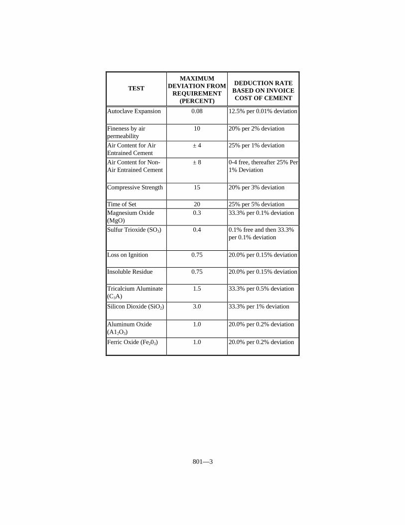
801—3
TEST
MAXIMUMDEVIATION FROM
REQUIREMENT(PERCENT)
DEDUCTION RATEBASED ON INVOICECOST OF CEMENT
Autoclave Expansion 0.08 12.5% per 0.01% deviation
Fineness by airpermeability
10 20% per 2% deviation
Air Content for AirEntrained Cement
± 4 25% per 1% deviation
Air Content for Non-Air Entrained Cement
± 8 0-4 free, thereafter 25% Per1% Deviation
Compressive Strength 15 20% per 3% deviation
Time of Set 20 25% per 5% deviationMagnesium Oxide(MgO)
0.3 33.3% per 0.1% deviation
Sulfur Trioxide (SO3) 0.4 0.1% free and then 33.3%per 0.1% deviation
Loss on Ignition 0.75 20.0% per 0.15% deviation
Insoluble Residue 0.75 20.0% per 0.15% deviation
Tricalcium Aluminate(C3A)
1.5 33.3% per 0.5% deviation
Silicon Dioxide (SiO2) 3.0 33.3% per 1% deviation
Aluminum Oxide(A12O3)
1.0 20.0% per 0.2% deviation
Ferric Oxide (Fe203) 1.0 20.0% per 0.2% deviation

802—1
SECTION 802 ADMIXTURES FOR CONCRETE
802.01 REQUIREMENTS. Provide admixtures conforming to the followingrequirements:
802.01.01 Air-Entraining. AASHTO M 154, except the chloride content (as Cl)shall not exceed one percent by weight. The Department may require tests for bleeding,time of setting, and length change.
802.01.02 Water-Reducing and Retarding. AASHTO M 194, Type D, except therelative durability factor shall not be less than 90 and the chloride content (as Cl) shall notexceed one percent by weight.
802.01.03 Water-Reducing. AASHTO M 194, Type A, except the relativedurability factor shall not be less than 90 and the chloride content (as Cl) shall not exceedone percent by weight.
802.01.04 Water-Reducing and Accelerating. AASHTO M 194, Type E, exceptthe relative durability factor shall not be less than 90 and the chloride content (as Cl) shallnot exceed one percent by weight. Use water reducing and accelerating admixture onlywhen the Engineer has reviewed proposed procedures for mixing, handling, and placingthe concrete, and has given written permission to proceed.
802.01.05 Water-Reducing, High Range. AASHTO M 194, Type F, except therelative durability factor shall not be less than 90 and the chloride content (as Cl) shall notexceed one percent by weight.
802.01.06 Water-Reducing, High Range and Retarding. AASHTO M 194, TypeG, except the relative durability factor shall not be less than 90 and the chloride content (asCl) shall not exceed one percent by weight.
802.01.07 Accelerating. AASHTO M 194, Type C, except the relative durabilityfactor shall not be less than 90 and the chloride content (as C1) shall not exceed onepercent by weight.
802.02 APPROVAL. Select admixtures from the Department’s List of ApprovedMaterials. The Department places admixtures on the list based on evidence of compliancewith requirements when determined by either tests performed by the Department; certifiedtest data furnished by a recognized laboratory providing such laboratory shall be oneregularly inspected by the Cement and Concrete Reference Laboratory of ASTM; for air-entraining admixtures that are aqueous solutions of Vinsol Resin, manufacturer’s shallsubmit a certification in the following form:
This is to certify that the product (trade name) as manufacturedand sold by (company) is an aqueous solution of Vinsol Resin that hasbeen neutralized with sodium hydroxide. The ratio of sodiumhydroxide to Vinsol Resin is one part of sodium hydroxide to (number)parts of Vinsol Resin. The percentage of solids based on the residuedried at 105 ΕC is (number). No other additive or chemical agent ispresent in this solution.
The Engineer will not require testing of admixtures included on the Department’s Listof Approved Materials at the time of their use unless there is indication in actual field useof harmful effects on the properties of the concrete or when the Engineer considers testingnecessary for other reasons.
The Department will continue to include an admixture on the list contingent upon
802—2
satisfactory performance in actual project use and an annual certification containing thefollowing information:
1) A statement that the admixture to be furnished during the particular calendar year isof the same composition as that previously approved for inclusion on the approvedlist.
2) A statement that the admixture conforms to the appropriate requirements of AASHTOM 194 or AASHTO M 154, as applicable.
3) A statement that the chloride content (as Cl) does not exceed one percent by weight.4) A statement that notification will be made to the Division of Materials of any changes
in composition before furnishing the material to projects.
The Department provides the specific details governing verification and documentingapproved status of admixtures at the time of use in the Department’s Manual of FieldSampling and Testing Practices.
803—1
SECTION 803 WATER
803.01 GENERAL. Use water for mixing or curing concrete, emulsified asphalt, orother similar materials that is reasonably clean and free from oil, salt, acid, alkali, sugar,vegetable, or other substances injurious to the finished product. The Engineer may test thewater at any time for its suitability for a particular use.
The Engineer will ordinarily accept water supplied by public distribution systemswithout testing.
The Engineer will require testing of mixing water for use in concrete when not from apublic distribution system.
Provide water that when tested by KM 64-226 does not contain impurities in excess ofthe following limits:
Acidity or Alkalinity Calculated 0.05 Percentin terms of Calcium Carbonate
Total Organic Solids 0.10 PercentTotal Inorganic Solids 0.10 PercentChloride Content (as Cl) 1,000 parts per million

804—1
SECTION 804 FINE AGGREGATES
804.01 GENERAL. Fine aggregates include, but at the discretion of the Engineer arenot limited to, natural sand, crushed sand, conglomerate sand, mortar sand, mineral filler,and lightweight aggregates where permitted.
The Department’s List of Approved Materials includes the Aggregate Source List andthe list of Class A and Class B Polish-Resistant Aggregate Sources.
804.01.01 Natural Sand. Provide fine granular material resulting from the naturaldisintegration of rock.
804.01.02 Crushed Sand. Provide fine granular material resulting from crushing ofstone or gravel. Includes slag where permitted.
804.01.03 Conglomerate Sand. Provide natural materials primarily processed to thedesired sizes, without crushing. Conglomerate sand may include some crushed naturalmaterial.
804.01.04 Mortar Sand. Provide natural, crushed, or conglomerate sand suitable foruse in cement mortar.
804.01.05 Mineral Filler. Provide limestone dust, cement, fly ash, or other inertmineral matter.
804.02 APPROVAL. Provide fine aggregates from sources included on the AggregateSource List meeting the description and requirements specified in this section.
The Department will consider a source for inclusion on the Aggregate Source Listwhen the aggregate producer provides the following:
1) A Quality Control Plan.2) A satisfactory laboratory facility with all necessary testing equipment.3) A Qualified Aggregate Technician to perform the required testing.
When a supplier wishes to supply sand only for asphalt mixtures, Items 1, 2 and 3above will be waived. The Department may add the source to the Aggregate Source Listand restrict its use to asphalt mixtures.
Obtain the Department’s approval before furnishing aggregate from sources not onthe Aggregate Source List. The Department will sample the aggregate during stockpilingand test according to the Department’s Manual of Field Testing and Sampling Practices.
The Department will reject aggregate when excessive variation of gradation orphysical properties cause unworkable mixtures, mixture control problems, or non-conformance to the finished product or mixture requirements.
The Department will reject contaminated aggregate when the Engineer deems it couldbe detrimental to the finished product.
804.03 CONCRETE. Provide natural, crushed, or conglomerate sand. Use natural orconglomerate sands as fine aggregates in concrete intended as a wearing surface for traffic. The Department will allow any combination of natural, crushed, or conglomerate sandwhen the combination is achieved in the concrete plant weigh hopper. The Engineer mayallow other sands.
Conform to the following:
1) Sand Equivalent - 80 (minimum).2) Soundness - 10% loss (maximum).3) Friable Particles - 3.0% (maximum).4) Coal plus Lignite - 0.5% (maximum).
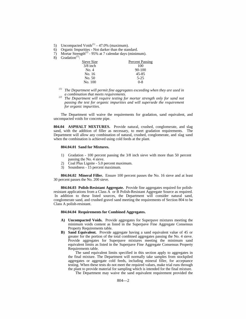
804—2
5) Uncompacted Voids(1) – 47.0% (maximum).6) Organic Impurities - Not darker than the standard.7) Mortar Strength(2) - 95% at 7 calendar days (minimum).8) Gradation(1):
Sieve Size Percent Passing3/8 inch 100
No. 4 90-100No. 16 45-85No. 50 5-25No. 100 0-8
(1) The Department will permit fine aggregates exceeding when they are used ina combination that meets requirements.
(2) The Department will require testing for mortar strength only for sand notpassing the test for organic impurities and will supersede the requirementfor organic impurities.
The Department will waive the requirements for gradation, sand equivalent, anduncompacted voids for concrete pipe.
804.04 ASPHALT MIXTURES. Provide natural, crushed, conglomerate, and slagsand, with the addition of filler as necessary, to meet gradation requirements. TheDepartment will allow any combination of natural, crushed, conglomerate, and slag sandwhen the combination is achieved using cold feeds at the plant.
804.04.01 Sand for Mixtures.
1) Gradation - 100 percent passing the 3/8 inch sieve with more than 50 percent passing the No. 4 sieve.
2) Coal Plus Lignite - 5.0 percent maximum.3) Soundness - 15 percent maximum.
804.04.02 Mineral Filler. Ensure 100 percent passes the No. 16 sieve and at least30 percent passes the No. 200 sieve.
804.04.03 Polish-Resistant Aggregate. Provide fine aggregates required for polish-resistant applications from a Class A or B Polish-Resistant Aggregate Source as required. In addition to these listed sources, the Department will consider natural sand,conglomerate sand, and crushed gravel sand meeting the requirements of Section 804 to beClass A polish-resistant.
804.04.04 Requirements for Combined Aggregates.
A) Uncompacted Voids. Provide aggregates for Superpave mixtures meeting theminimum voids content as listed in the Superpave Fine Aggregate ConsensusProperty Requirements table.
B) Sand Equivalent. Provide aggregate having a sand equivalent value of 45 orgreater for the portion of the total combined aggregates passing the No. 4 sieve.Provide aggregates for Superpave mixtures meeting the minimum sandequivalent limits as listed in the Superpave Fine Aggregate Consensus PropertyRequirements table.
The sand equivalent limits specified in this section apply to aggregates inthe final mixture. The Department will normally take samples from stockpiledaggregates or aggregate cold feeds, including mineral filler, for acceptancetesting. When these tests do not meet the required values, make trial runs throughthe plant to provide material for sampling which is intended for the final mixture.
The Department may waive the sand equivalent requirement provided the
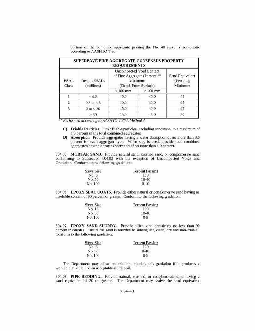
804—3
portion of the combined aggregate passing the No. 40 sieve is non-plasticaccording to AASHTO T 90.
SUPERPAVE FINE AGGREGATE CONSENSUS PROPERTYREQUIREMENTS
Uncompacted Void Contentof Fine Aggregate (Percent),(1) Sand Equivalent
ESAL Design ESALs Minimum (Percent),Class (millions) (Depth From Surface) Minimum
≤ 100 mm > 100 mm1 < 0.3 40.0 40.0 452 0.3 to < 3 40.0 40.0 453 3 to < 30 45.0 40.0 454 ≥ 30 45.0 45.0 50
(1) Performed according to AASHTO T 304, Method A.
C) Friable Particles. Limit friable particles, excluding sandstone, to a maximum of1.0 percent of the total combined aggregates.
D) Absorption. Provide aggregates having a water absorption of no more than 3.0percent for each aggregate type. When slag is used, provide total combinedaggregates having a water absorption of no more than 4.0 percent.
804.05 MORTAR SAND. Provide natural sand, crushed sand, or conglomerate sandconforming to Subsection 804.03 with the exception of Uncompacted Voids andGradation. Conform to the following gradation:
Sieve Size Percent PassingNo. 8 100No. 50 10-40No. 100 0-10
804.06 EPOXY SEAL COATS. Provide either natural or conglomerate sand having aninsoluble content of 90 percent or greater. Conform to the following gradation:
Sieve Size Percent PassingNo. 16 100No. 50 10-40No. 100 0-5
804.07 EPOXY SAND SLURRY. Provide silica sand containing no less than 90percent insolubles. Ensure the sand is rounded to subangular, clean, dry and non-friable. Conform to the following gradation:
Sieve Size Percent PassingNo. 8 100No. 50 0-40
No. 100 0-5
The Department may allow material not meeting this gradation if it produces aworkable mixture and an acceptable slurry seal.
804.08 PIPE BEDDING. Provide natural, crushed, or conglomerate sand having asand equivalent of 20 or greater. The Department may waive the sand equivalent

804—4
requirement when the portion passing the No. 40 sieve is non-plastic according toAASHTO T 90. Conform to the following gradation:
Sieve Size Percent Passing3/8 inch 100No. 100 0-15
804.09 UNDERDRAINS, EMBANKMENT DRAINAGE BLANKET, ANDNATURAL SAND FOR DRAINAGE AND BACKFILL. Provide natural sand havinga sand equivalent of 70 or greater. Conform to the following gradation:
Sieve Size Percent Passing3/8 inch 100
No. 4 75-100No. 100 0-8
804.10 GRADATION ACCEPTANCE OF NON-SPECIFICATION FINEAGGREGATE. When reasonably acceptable work has been produced using theaggregate in question, the Department may accept the work according to Subsection105.04. When the Engineer determines that the aggregate not conforming to gradationrequirements may be left in place, the Department will accept the aggregate at a reductionin the Contract unit bid price for the work containing the aggregate according to thefollowing procedures. The Department will not consider these procedures a means tocontinue accepting non-specification aggregates.
The Department will base the reduction on the invoice price for the aggregate at thesource. When satisfactory invoices are not furnished, the Department will use current binprices for that source on file with the Cabinet’s Division of Purchases. The maximumdeduction for non-specification material, which is allowed to remain in place, is 50percent.
When aggregate fails to conform to gradation on more than one sieve, the Departmentwill apply the largest payment reduction.
The Department will define a lot based on the smallest definable quantity of materialrepresented by acceptance test results, either passing results or failing results, or both. Normally, the Department will average all test results for the lot to determine the test resultfor payment according to the deduction tables. However, when test results are notreasonably uniform the Department will not average the high and low test results within alot. The Department will assign each test result to equal quantities in new smaller lots inproportion to the number of tests representing the original lot. When daily tests areperformed, the lot will be a day’s production unless the Department defines a smaller lot.
When 2 consecutive lots contain non-specification material, discontinue the use of theaggregate until the Department makes a decision concerning the overall acceptability ofthe aggregate from that source.
The Department will not impose a reduction in payment for quantities less than 50tons unless the Engineer deems it necessary.
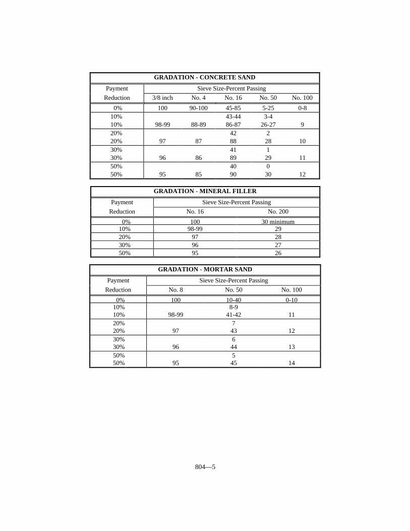
804—5
GRADATION - CONCRETE SAND
Payment Sieve Size-Percent PassingReduction 3/8 inch No. 4 No. 16 No. 50 No. 100
0% 100 90-100 45-85 5-25 0-810% 43-44 3-410% 98-99 88-89 86-87 26-27 920% 42 220% 97 87 88 28 1030% 41 130% 96 86 89 29 1150% 40 050% 95 85 90 30 12
GRADATION - MINERAL FILLER
Payment Sieve Size-Percent PassingReduction No. 16 No. 200
0% 100 30 minimum10% 98-99 2920% 97 2830% 96 2750% 95 26
GRADATION - MORTAR SAND
Payment Sieve Size-Percent PassingReduction No. 8 No. 50 No. 100
0% 100 10-40 0-1010% 8-910% 98-99 41-42 1120% 720% 97 43 1230% 630% 96 44 1350% 550% 95 45 14
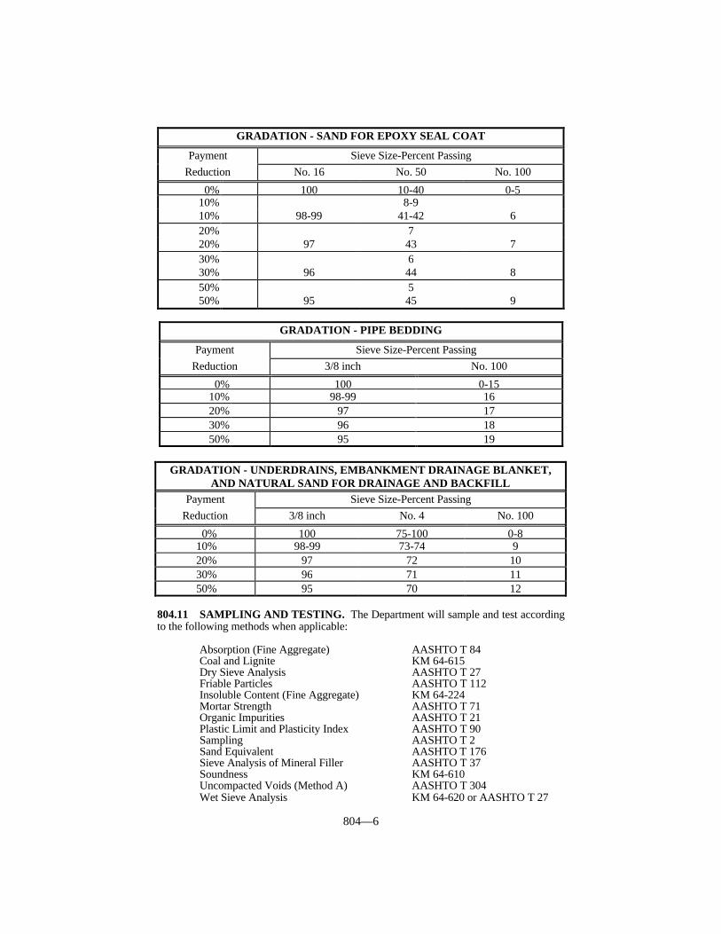
804—6
804.11 SAMPLING AND TESTING. The Department will sample and test accordingto the following methods when applicable:
Absorption (Fine Aggregate) AASHTO T 84Coal and Lignite KM 64-615Dry Sieve Analysis AASHTO T 27Friable Particles AASHTO T 112Insoluble Content (Fine Aggregate) KM 64-224Mortar Strength AASHTO T 71Organic Impurities AASHTO T 21Plastic Limit and Plasticity Index AASHTO T 90Sampling AASHTO T 2Sand Equivalent AASHTO T 176Sieve Analysis of Mineral Filler AASHTO T 37Soundness KM 64-610Uncompacted Voids (Method A) AASHTO T 304Wet Sieve Analysis KM 64-620 or AASHTO T 27
GRADATION - SAND FOR EPOXY SEAL COAT
Payment Sieve Size-Percent PassingReduction No. 16 No. 50 No. 100
0% 100 10-40 0-510% 8-910% 98-99 41-42 620% 720% 97 43 730% 630% 96 44 850% 550% 95 45 9
GRADATION - PIPE BEDDING
Payment Sieve Size-Percent PassingReduction 3/8 inch No. 100
0% 100 0-1510% 98-99 1620% 97 1730% 96 1850% 95 19
GRADATION - UNDERDRAINS, EMBANKMENT DRAINAGE BLANKET,AND NATURAL SAND FOR DRAINAGE AND BACKFILL
Payment Sieve Size-Percent PassingReduction 3/8 inch No. 4 No. 100
0% 100 75-100 0-810% 98-99 73-74 920% 97 72 1030% 96 71 1150% 95 70 12

805—1
SECTION 805 COARSE AGGREGATES
805.01 GENERAL. Coarse aggregates include, but at the discretion of the Engineer arenot limited to, crushed stone and crushed or uncrushed gravel. Includes lightweightaggregates or slag where permitted.
The Department’s List of Approved Materials includes the Aggregate Source List andthe list of Class A and Class B Polish-Resistant Aggregate Sources.
805.02 APPROVAL. Provide coarse aggregates from sources included on theAggregate Source List meeting the description and requirements specified in this section.
The Department will consider a source for inclusion on the Aggregate Source Listwhen the aggregate producer provides the following:
1) A Quality Control Plan.2) A satisfactory laboratory facility with all necessary testing equipment.3) A Qualified Aggregate Technician to perform the required testing.
Obtain the Department’s approval before furnishing aggregate from sources not onthe Aggregate Source List. The Department will sample the aggregate during stockpilingand test according to the Department’s Manual of Field Testing and Sampling Practices.
The Department will reject aggregate when excessive variation of gradation orphysical properties cause unworkable mixtures, mixture control problems, or non-conformance to the finished product or mixture requirements.
Coarse aggregates are subject to preliminary source approval.
805.03 GENERAL REQUIREMENTS. Provide coarse aggregates that are free ofobjectionable amounts of clay lumps, dirt coatings, and foreign material. The Departmentwill reject contaminated aggregate when the Engineer deems it could be detrimental to thefinished product.
805.03.01 Soundness and Shale. Conform to the following:
SHALE SOUNDNESS AGGREGATE USE PERMITTED(1) REQUIREMENT
(Maximum %) (Maximum %)
Portland Cement Concrete MixturesAggregate for Bridge Decks, Bridge Deck Overlays,and Bridge Barrier Walls 1.0 9All Other Concrete Classes and Uses 2.0 12
Asphalt MixturesAggregate for Polish Resistant Surfaces and AsphaltSurface Under OGFC:
Limestone and Dolomite 1.0 9Other Aggregate Types 2.0 12
All Other Asphalt Mixtures 2.0 15
Other UsesSizes No. 610 or 710 When Used for Aggregate
Surfacing, Traffic Bound Base, and Maintenance 5.0 18Riprap and Channel Lining 2.0 12All Other Uses 2.0 15
(1) The Department will determine shale quantity by visual estimation for Riprapand Channel Lining and according to KM 64-604 for all other aggregate.
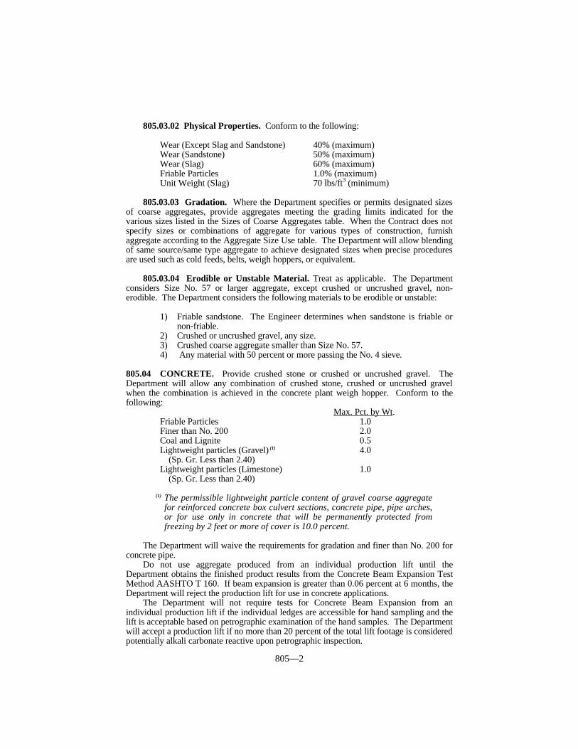
805—2
805.03.02 Physical Properties. Conform to the following:
Wear (Except Slag and Sandstone) 40% (maximum)Wear (Sandstone) 50% (maximum)Wear (Slag) 60% (maximum)Friable Particles 1.0% (maximum)Unit Weight (Slag) 70 lbs/ft3 (minimum)
805.03.03 Gradation. Where the Department specifies or permits designated sizesof coarse aggregates, provide aggregates meeting the grading limits indicated for thevarious sizes listed in the Sizes of Coarse Aggregates table. When the Contract does notspecify sizes or combinations of aggregate for various types of construction, furnishaggregate according to the Aggregate Size Use table. The Department will allow blendingof same source/same type aggregate to achieve designated sizes when precise proceduresare used such as cold feeds, belts, weigh hoppers, or equivalent.
805.03.04 Erodible or Unstable Material. Treat as applicable. The Departmentconsiders Size No. 57 or larger aggregate, except crushed or uncrushed gravel, non-erodible. The Department considers the following materials to be erodible or unstable:
1) Friable sandstone. The Engineer determines when sandstone is friable ornon-friable.
2) Crushed or uncrushed gravel, any size.3) Crushed coarse aggregate smaller than Size No. 57.4) Any material with 50 percent or more passing the No. 4 sieve.
805.04 CONCRETE. Provide crushed stone or crushed or uncrushed gravel. TheDepartment will allow any combination of crushed stone, crushed or uncrushed gravelwhen the combination is achieved in the concrete plant weigh hopper. Conform to thefollowing:
Max. Pct. by Wt.Friable Particles 1.0Finer than No. 200 2.0Coal and Lignite 0.5Lightweight particles (Gravel) (1) 4.0
(Sp. Gr. Less than 2.40)Lightweight particles (Limestone) 1.0
(Sp. Gr. Less than 2.40)
(1) The permissible lightweight particle content of gravel coarse aggregatefor reinforced concrete box culvert sections, concrete pipe, pipe arches,or for use only in concrete that will be permanently protected fromfreezing by 2 feet or more of cover is 10.0 percent.
The Department will waive the requirements for gradation and finer than No. 200 forconcrete pipe.
Do not use aggregate produced from an individual production lift until theDepartment obtains the finished product results from the Concrete Beam Expansion TestMethod AASHTO T 160. If beam expansion is greater than 0.06 percent at 6 months, theDepartment will reject the production lift for use in concrete applications.
The Department will not require tests for Concrete Beam Expansion from anindividual production lift if the individual ledges are accessible for hand sampling and thelift is acceptable based on petrographic examination of the hand samples. The Departmentwill accept a production lift if no more than 20 percent of the total lift footage is consideredpotentially alkali carbonate reactive upon petrographic inspection.
805—3
805.04.01 JPC Base, JPC Pavement, JPC Shoulders, and Concrete for BridgeDecks. The Department will subject coarse aggregates that are to be used in JPC base,JPC pavement, JPC shoulders, bridge decks, and concrete overlays to freeze-thaw testingaccording to KM 64-626. The Department will allow sources having expansions of 0.06percent or less to supply any size coarse aggregate listed in the Aggregate Size Use table,providing that size or a larger size has tested satisfactorily. When sources have expansionsof more than 0.06 percent the Department will:
1) Reject the material.2) Limit to the permitted sizes determined from acceptable freeze-thaw testing.3) Allow the submittal of a proposal to the Engineer for production of acceptable
coarse aggregate. The Department will require acceptable freeze-thaw testsresults before approving any proposal.
805.04.02 Lightweight Aggregate. When the Department allows lightweightaggregate conform to the following:
1) Dry Loose Unit Weight. As appropriate or as specified, AASHTO M 195, Table2.
2) Gradation (by weight). Provide size specified, AASHTO M 195, Table 1.3) Wear. 50 percent maximum.4) Soundness. 9 percent loss maximum.5) Friable Particles. 1.0 percent maximum.6) Deleterious Particles. 1.0 percent maximum.7) Freeze-Thaw Resistance. 85 percent minimum durability factor and 0.06 percent
maximum length change according to KM 64-626.8) Provide creep, shrinkage, and tensile splitting strength test data made on concrete
produced from the lightweight aggregate when the Engineer requests.9) If lightweight aggregate from an unapproved source is proposed for use, notify
the Engineer of the aggregate source and proposed concrete mix design at least10 weeks before any lightweight aggregate concrete is placed, so the Departmentmay subject the lightweight aggregate to testing as outlined above, plus anyadditional testing as deemed necessary and indicated in AASHTO M 195. Atthe Departments option, suitable documentation of such testing by anindependent testing laboratory may be accepted.
805.05 ASPHALT MIXTURES AND SEALS. Provide crushed stone, crushed gravel,or blast furnace slag. The Department will allow any combination of crushed stone,crushed gravel, or blast furnace slag when the combination is achieved using cold feeds atthe asphalt plant. The Engineer may allow other coarse aggregates.
805.05.01 Absorption. Provide aggregates having a water absorption of no morethan 3.0 percent for each size and type. When blast furnace slag slag is used, provide totalcombined aggregates having a water absorption of no more than 4.0 percent.
805.05.02 Crushed Particles. Applies to the total combined aggregates retained ona No. 4 sieve, including the material from the fine aggregate. Conform to the following:
A) Superpave Mixtures. Minimum percent crushed requirements as listed in theSuperpave Coarse Aggregate Consensus Property Requirements table.
B) Open-Graded Friction Courses. Minimum 95 percent one or more crushedfaces and 75 percent 2 or more crushed faces.
C) Seal Coats. Minimum 90 percent one or more crushed faces.D) Other Mixtures. Unless otherwise specified, minimum 75 percent one or more
crushed faces.

805—4
SUPERPAVE COARSE AGGREGATE CONSENSUS PROPERTYREQUIREMENTSCoarse Aggregate Angularity Flat and
(Percent) Elongated(1)
ESAL Design ESALs Minimum Depth From Surface (Percent),Class (millions) ≤ 100 mm > 100 mm maximum
Crushed Faces Crushed Faces≥1 ≥2 ≥1 ≥2
1 < 0.3 75 - 75 - 102 0.3 to < 3 75 - 75 - 103 3 to < 30 95 90 80 75 104 ≥ 30 100 100 100 100 10
(1) Criterion based on a 5:1 maximum-to-minimum ratio.
805.05.03 Flat and Elongated. Provide aggregates for Superpave mixtures notexceeding the flat and elongated maximum as listed in the Superpave Coarse AggregateConsensus Property Requirements table.
805.05.04 Finer Than No. 200 (Seals). Provide coarse aggregates having no morethan 3.0 percent passing the No. 200 sieve.
805.05.05 Polish-Resistant Aggregate. Provide coarse aggregates required forpolish-resistant applications from a Class A or Class B Polish-Resistant AggregateSource, as applicable, based on mixture designation of aggregate type.
805.06 DENSE GRADED AGGREGATE (DGA) AND CRUSHED STONE BASE(CSB). Provide crushed stone having a sand equivalent value of 30 or greater withmineral filler as needed to meet gradation requirements. The Department may waive thesand equivalent requirement when the portion passing the No. 40 sieve has a plasticityindex of 4 or less according to AASHTO T 90.
805.07 FREE DRAINING BEDDING AND BACKFILL. Provide crushed stone orcrushed or uncrushed gravel. The Department will allow a shale content of 5 percentproviding the combined shale, friable particles, and minus No. 200 content does notexceed 5 percent. Conform to the following gradation:
Sieve Size Percent Passing1 1/2 inch 100
No. 4 0-30
805.08 COARSE AGGREGATES FOR UNDERDRAINS. Furnish crushed oruncrushed aggregate, including pea gravel meeting the quality requirements of Section 805with the following exception: The Department will allow a shale content of 5 percentproviding the combined shale, friable particles, and minus No. 200 content does notexceed 5 percent. Conform to the following gradation:
Sieve Size Percent Passing1 1/2 inch 100
No. 4 0-30No. 100 0-5
805.09 COARSE AGGREGATE FOR ROCK DRAINAGE BLANKET. Provide
805—5
crushed or uncrushed aggregate, including pea gravel, meeting the quality requirements ofthis section with the following additional requirement: Ensure the minus No. 200 contentdoes not exceed 5 percent. When the material includes a significant amount of individualfragments greater than 1 1/2 inches, the Engineer may accept the minus No. 200 portionbased on visual inspection. Conform to the following gradation:
Sieve Size Percent Passing4 inch 100No. 4 0-30
805.10 GRANULAR EMBANKMENT. Provide granular material up to 12-inchmaximum size with a maximum shale content of 5 percent. Use either:
1) Engineer approved shot limestone or sandstone from roadway excavation, borrowexcavation, or another approved source.
2) Crushed stone, crushed or uncrushed gravel, or crushed or natural sand meetinggeneral requirements of Section 804 and this section, with a minus No. 200 contentnot exceeding 10.0 percent.
805.11 STRUCTURE GRANULAR BACKFILL. Provide crushed or uncrushedaggregate meeting the quality requirements of this section. When the material includes asignificant amount of individual fragments greater than 1 1/2 inches, the Engineer mayvisually accept the minus No. 200 portion. Conform to the following gradation:
Sieve Size Percent Passing4 inch 100No. 4 0-10
No. 200 0-5
805.12 REINFORCED FILL MATERIAL. Obtain the Engineer’s approval formaterial quality before use. Ensure the material is reasonably free of shale or otherdeleterious material. Conform to the following:
A) Gradation. Conform to Subsection 805.11.B) Resistivity. Greater than 3,000 ohm-cm (applicable only when granular fill has
more than 50 percent passing the No. 4 sieve).C) PH. Between 5-10.D) Chlorides. Less than 200 parts per million.E) Sulfates. Less than 1,000 parts per million.F) Angle of Internal Friction. Greater than or equal to 34 degrees. When
providing gap-graded materials, single size aggregates, uncrushed gravel, orblends including uncrushed gravel, furnish a test report showing the 34 degreeminimum internal friction angle is met. Test sample according to AASHTO T236 compacted to 95 percent of AASHTO T 99 Methods C or D at optimummoisture content. When such materials are approved, the Engineer will performsampling and testing on the project as necessary to assure that the materialfurnished is closely similar to that approved.
805.13 SLOPE PROTECTION AND CHANNEL LINING.
805.13.01 Cyclopean Stone Riprap and Channel Lining Class III. Providematerial meeting the general requirements of Section 805. No less than 80 percent, byvolume, of individual stones that range in size from 1/4 to 1 1/2 cubic feet. TheDepartment will allow stones of smaller sizes for filling voids in the upper surface anddressing to the proper slope.
805.13.02 Crushed Aggregate Slope Protection. Furnish aggregate meeting the
805—6
general requirements of Section 805. Conform to the following gradation (Coarseaggregate sizes No. 1 and No. 2 conform to this requirement):
Sieve Size Percent Passing4 inch 100
2 1/2 inch 25-1001 1/2 inch 0-15
805.13.03 Channel Lining, Class IA. Provide crushed stone meeting the generalrequirements of this section. Use a crusher, grizzly, or sieve with openings to produce agrading that 100 percent passes the 5 inch sieve, no more than 20 percent of the finishedproduct passes through square openings 1 1/2 by 1 1/2 inches.
805.13.04 Channel Lining, Class II. Provide crushed stone meeting the generalrequirements of this section. Use a crusher, grizzly, or sieve with openings to produce agrading that 100 percent passes the 9-inch sieve, and no more than 20 percent of thefinished product passes through square openings 5 by 5 inches.
805.13.05 Channel Lining, Class IV. Provide material excavated and preparedaccording to Section 204.
805.13.06 Stone for Gabions. Provide aggregate meeting the general requirementsof this section and be of such gradation that 100 percent passes through a square openingof 12 by 12 inches and 100 percent is retained on a 4 inch sieve.
805.14 AGGREGATE SURFACING, TRAFFIC-BOUND BASE, ANDMAINTENANCE. When providing size No. 610 or 710 coarse aggregate for aggregatesurfacing (shoulders, entrances, mailbox turn outs, or similar items), traffic bound baseand maintenance operations; furnish aggregate meeting the grading requirements in Sizesof Coarse Aggregates table, with no more than 12 percent finer than a No. 200 sieve.
When providing DGA for aggregate surfacing, traffic bound base, and maintenanceoperations conform to the grading requirement in Sizes of Coarse Aggregates table.
805.15 GRADATION ACCEPTANCE OF NON-SPECIFICATION COARSEAGGREGATE. It is intended that all aggregate purchased for Department work meet therequirements of this section. When reasonably acceptable work has been produced usingthe aggregate in question, the Department may accept the work according to Subsection105.04. When the Engineer determines that the aggregate not conforming to gradationrequirements may be left in place, the Department will accept the aggregate at a reductionin the Contract unit bid price for the work containing the aggregate according to thefollowing procedures. The Department will not consider these procedures a means tocontinue accepting non-specification aggregates.
The Department will base the reduction on the invoice price for the aggregate at thesource. When satisfactory invoices are not furnished, the Department will use current binprices for that source on file with the Cabinet’s Division of Purchases. The maximumdeduction for non-specification material which is allowed to remain in place is 50 percent. When aggregate fails to conform to gradation on more than one sieve, the Department willapply the largest payment reduction.
The Department will define a lot based on the smallest definable quantity of materialrepresented by acceptance test results, either passing results or failing results, or both. Normally, the Department will average all test results for the lot to determine the test resultfor payment according to the deduction tables. However, when test results are notreasonably uniform the Department will not average the high and low test results within alot. The Department will assign each test result to equal quantities in new smaller lots inproportion to the number of tests representing the original lot. When daily tests areperformed, the lot will be a day’s production unless the Department defines a smaller lot.
When 2 consecutive lots contain non-specification material, discontinue the use of the
805—7
aggregate until the Department makes a decision concerning the overall acceptability ofthe aggregate from that source.
The Department will not impose a reduction in payment for quantities less than 50tons unless the Engineer deems it necessary.
GRADATION - SIZE NO. 1
Payment Sieve Size-Percent Passing
Reduction 4 inch 3 1/2 inch 2 1/2 inch 1 1/2 inch 3/4 inch
0% 100 90-100 25-60 0-15 0-510% 61-6210% 98-99 88-89 23-24 16-17 6-720% 2220% 97 87 63 18 830% 2130% 96 86 64 19 950% 2050% 95 85 65 20 10
GRADATION - SIZE NO. 2
Payment Sieve Size-Percent Passing
Reduction 3 inch 2 1/2 inch 2 inch 1 1/2 inch 3/4 inch
0% 100 90-100 35-70 0-15 0-510% 33-3410% 98-99 88-89 71-72 16-17 6-720% 3220% 97 87 73 18 830% 3130% 96 86 74 19 950% 3050% 95 85 75 20 10
GRADATION - SIZE NO. 23
Payment Sieve Size-Percent Passing
Reduction 3 inch 2 inch 1 inch 1/2 inch
0% 100 40-90 0-15 0-510% 38-3910% 98-99 91-92 16-17 6-720% 3720% 97 93 18 830% 3630% 96 94 19 950% 3550% 95 95 20 10
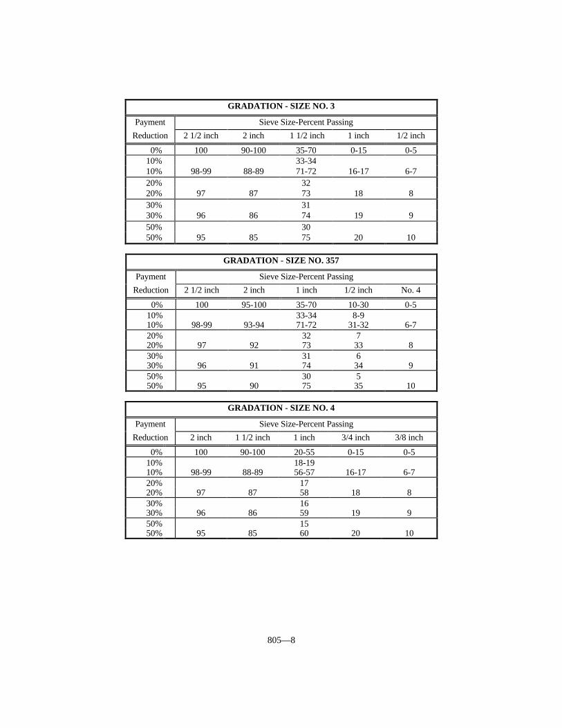
805—8
GRADATION - SIZE NO. 3
Payment Sieve Size-Percent Passing
Reduction 2 1/2 inch 2 inch 1 1/2 inch 1 inch 1/2 inch
0% 100 90-100 35-70 0-15 0-510% 33-3410% 98-99 88-89 71-72 16-17 6-720% 3220% 97 87 73 18 830% 3130% 96 86 74 19 950% 3050% 95 85 75 20 10
GRADATION - SIZE NO. 357
Payment Sieve Size-Percent Passing
Reduction 2 1/2 inch 2 inch 1 inch 1/2 inch No. 4
0% 100 95-100 35-70 10-30 0-510% 33-34 8-910% 98-99 93-94 71-72 31-32 6-720% 32 720% 97 92 73 33 830% 31 630% 96 91 74 34 950% 30 550% 95 90 75 35 10
GRADATION - SIZE NO. 4
Payment Sieve Size-Percent Passing
Reduction 2 inch 1 1/2 inch 1 inch 3/4 inch 3/8 inch
0% 100 90-100 20-55 0-15 0-510% 18-1910% 98-99 88-89 56-57 16-17 6-720% 1720% 97 87 58 18 830% 1630% 96 86 59 19 950% 1550% 95 85 60 20 10
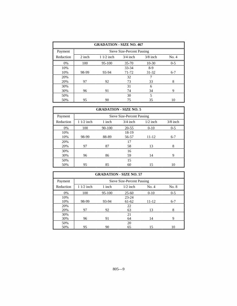
805—9
GRADATION - SIZE NO. 467
Payment Sieve Size-Percent Passing
Reduction 2 inch 1 1/2 inch 3/4 inch 3/8 inch No. 4
0% 100 95-100 35-70 10-30 0-510% 33-34 8-910% 98-99 93-94 71-72 31-32 6-720% 32 720% 97 92 73 33 830% 31 630% 96 91 74 34 950% 30 550% 95 90 75 35 10
GRADATION - SIZE NO. 5
Payment Sieve Size-Percent Passing
Reduction 1 1/2 inch 1 inch 3/4 inch 1/2 inch 3/8 inch
0% 100 90-100 20-55 0-10 0-510% 18-1910% 98-99 88-89 56-57 11-12 6-720% 1720% 97 87 58 13 830% 1630% 96 86 59 14 950% 1550% 95 85 60 15 10
GRADATION - SIZE NO. 57
Payment Sieve Size-Percent Passing
Reduction 1 1/2 inch 1 inch 1/2 inch No. 4 No. 8
0% 100 95-100 25-60 0-10 0-510% 23-2410% 98-99 93-94 61-62 11-12 6-720% 2220% 97 92 63 13 830% 2130% 96 91 64 14 950% 2050% 95 90 65 15 10
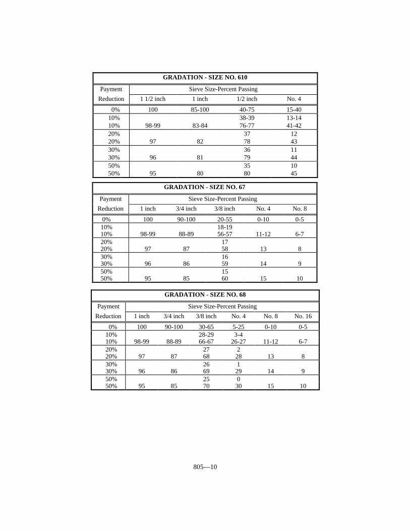
805—10
GRADATION - SIZE NO. 610
Payment Sieve Size-Percent Passing
Reduction 1 1/2 inch 1 inch 1/2 inch No. 4
0% 100 85-100 40-75 15-4010% 38-39 13-1410% 98-99 83-84 76-77 41-4220% 37 1220% 97 82 78 4330% 36 1130% 96 81 79 4450% 35 1050% 95 80 80 45
GRADATION - SIZE NO. 67
Payment Sieve Size-Percent Passing
Reduction 1 inch 3/4 inch 3/8 inch No. 4 No. 8
0% 100 90-100 20-55 0-10 0-510% 18-1910% 98-99 88-89 56-57 11-12 6-720% 1720% 97 87 58 13 830% 1630% 96 86 59 14 950% 1550% 95 85 60 15 10
GRADATION - SIZE NO. 68
Payment Sieve Size-Percent Passing
Reduction 1 inch 3/4 inch 3/8 inch No. 4 No. 8 No. 16
0% 100 90-100 30-65 5-25 0-10 0-510% 28-29 3-410% 98-99 88-89 66-67 26-27 11-12 6-720% 27 220% 97 87 68 28 13 830% 26 130% 96 86 69 29 14 950% 25 050% 95 85 70 30 15 10
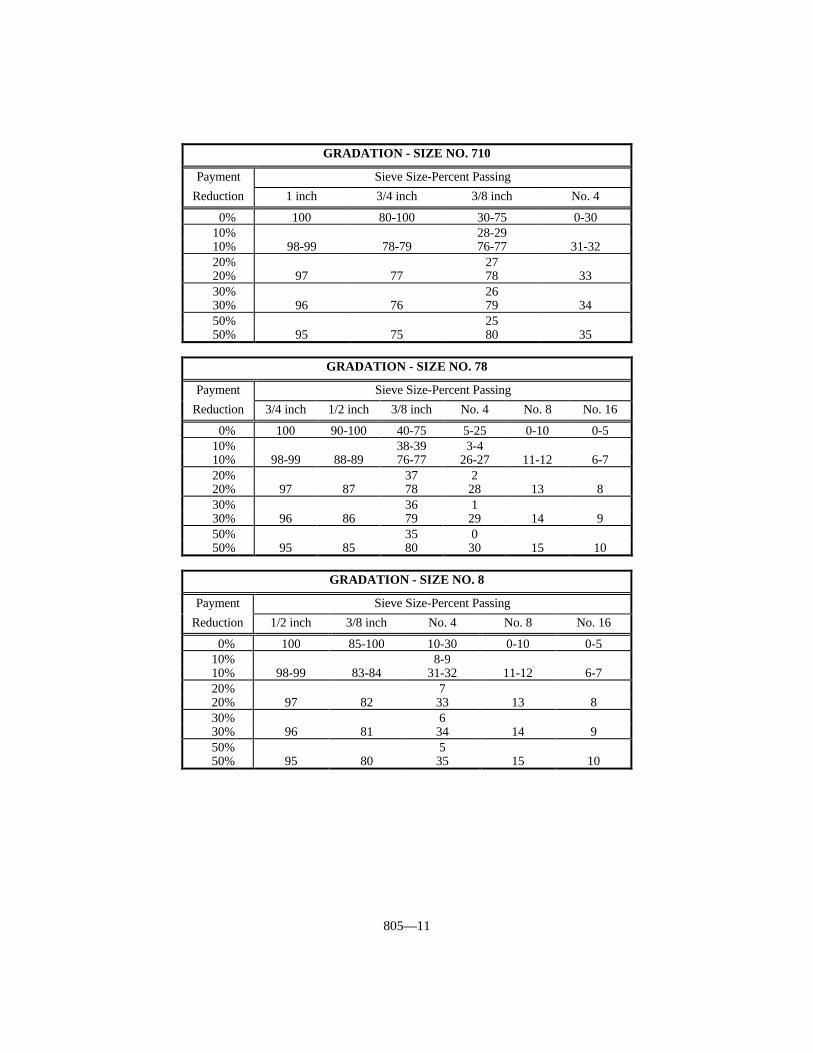
805—11
GRADATION - SIZE NO. 710
Payment Sieve Size-Percent Passing
Reduction 1 inch 3/4 inch 3/8 inch No. 4
0% 100 80-100 30-75 0-3010% 28-2910% 98-99 78-79 76-77 31-3220% 2720% 97 77 78 3330% 2630% 96 76 79 3450% 2550% 95 75 80 35
GRADATION - SIZE NO. 78
Payment Sieve Size-Percent Passing
Reduction 3/4 inch 1/2 inch 3/8 inch No. 4 No. 8 No. 16
0% 100 90-100 40-75 5-25 0-10 0-510% 38-39 3-410% 98-99 88-89 76-77 26-27 11-12 6-720% 37 220% 97 87 78 28 13 830% 36 130% 96 86 79 29 14 950% 35 050% 95 85 80 30 15 10
GRADATION - SIZE NO. 8
Payment Sieve Size-Percent Passing
Reduction 1/2 inch 3/8 inch No. 4 No. 8 No. 16
0% 100 85-100 10-30 0-10 0-510% 8-910% 98-99 83-84 31-32 11-12 6-720% 720% 97 82 33 13 830% 630% 96 81 34 14 950% 550% 95 80 35 15 10

805—12
GRADATION - SIZE NO. 9-M
Payment Sieve Size-Percent Passing
Reduction 1/2 inch 3/8 inch No. 4 No. 8
0% 100 75-100 0-25 0-510% 98-99 73-74 26-27 6-720% 97 72 28 830% 96 71 29 950% 95 70 30 10
GRADATION - SIZE NO. 10
Payment Sieve Size-Percent Passing
Reduction 3/8 inch No. 4 No. 100
0% 100 85-100 10-3010% 8-910% 98-99 83-84 31-3220% 720% 97 82 3330% 630% 96 81 3450% 550% 95 80 35
GRADATION - SIZE NO. 11
Payment Sieve Size-Percent Passing
Reduction 3/8 inch No. 4 No. 8 No. 100
0% 100 40-90 10-40 0-510% 38-39 8-910% 98-99 91-92 41-42 6-720% 37 720% 97 93 43 830% 36 630% 96 94 44 950% 35 550% 95 95 45 10
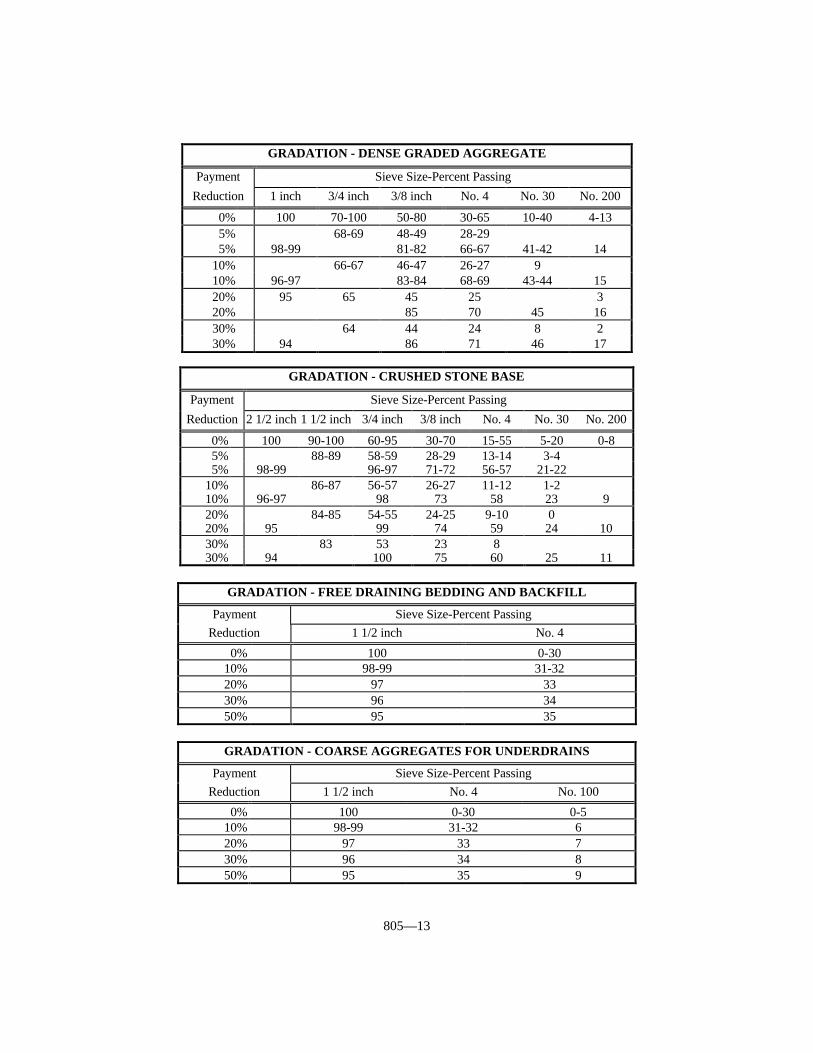
805—13
GRADATION - DENSE GRADED AGGREGATE
Payment Sieve Size-Percent Passing
Reduction 1 inch 3/4 inch 3/8 inch No. 4 No. 30 No. 200
0% 100 70-100 50-80 30-65 10-40 4-135% 68-69 48-49 28-295% 98-99 81-82 66-67 41-42 14
10% 66-67 46-47 26-27 910% 96-97 83-84 68-69 43-44 1520% 95 65 45 25 320% 85 70 45 1630% 64 44 24 8 230% 94 86 71 46 17
GRADATION - CRUSHED STONE BASE
Payment Sieve Size-Percent Passing
Reduction 2 1/2 inch 1 1/2 inch 3/4 inch 3/8 inch No. 4 No. 30 No. 200
0% 100 90-100 60-95 30-70 15-55 5-20 0-85% 88-89 58-59 28-29 13-14 3-45% 98-99 96-97 71-72 56-57 21-22
10% 86-87 56-57 26-27 11-12 1-210% 96-97 98 73 58 23 920% 84-85 54-55 24-25 9-10 020% 95 99 74 59 24 1030% 83 53 23 830% 94 100 75 60 25 11
GRADATION - FREE DRAINING BEDDING AND BACKFILL
Payment Sieve Size-Percent PassingReduction 1 1/2 inch No. 4
0% 100 0-3010% 98-99 31-3220% 97 3330% 96 3450% 95 35
GRADATION - COARSE AGGREGATES FOR UNDERDRAINS
Payment Sieve Size-Percent PassingReduction 1 1/2 inch No. 4 No. 100
0% 100 0-30 0-510% 98-99 31-32 620% 97 33 730% 96 34 850% 95 35 9
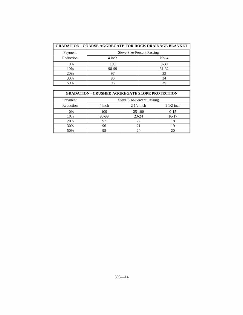
805—14
GRADATION - COARSE AGGREGATE FOR ROCK DRAINAGE BLANKET
Payment Sieve Size-Percent PassingReduction 4 inch No. 4
0% 100 0-3010% 98-99 31-3220% 97 3330% 96 3450% 95 35
GRADATION - CRUSHED AGGREGATE SLOPE PROTECTION
Payment Sieve Size-Percent PassingReduction 4 inch 2 1/2 inch 1 1/2 inch
0% 100 25-100 0-1510% 98-99 23-24 16-1720% 97 22 1830% 96 21 1950% 95 20 20
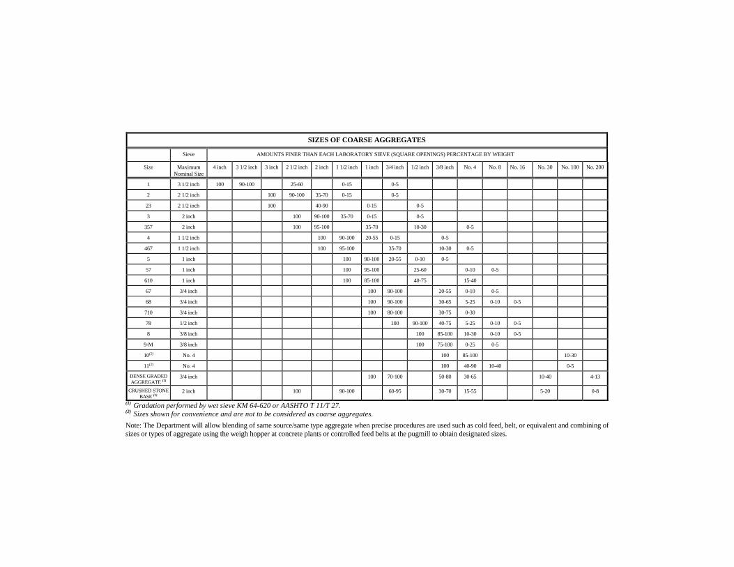
(1) Gradation performed by wet sieve KM 64-620 or AASHTO T 11/T 27.(2) Sizes shown for convenience and are not to be considered as coarse aggregates.
Note: The Department will allow blending of same source/same type aggregate when precise procedures are used such as cold feed, belt, or equivalent and combining ofsizes or types of aggregate using the weigh hopper at concrete plants or controlled feed belts at the pugmill to obtain designated sizes.
SIZES OF COARSE AGGREGATES
Sieve AMOUNTS FINER THAN EACH LABORATORY SIEVE (SQUARE OPENINGS) PERCENTAGE BY WEIGHT
Size MaximumNominal Size
4 inch 3 1/2 inch 3 inch 2 1/2 inch 2 inch 1 1/2 inch 1 inch 3/4 inch 1/2 inch 3/8 inch No. 4 No. 8 No. 16 No. 30 No. 100 No. 200
1 3 1/2 inch 100 90-100 25-60 0-15 0-5
2 2 1/2 inch 100 90-100 35-70 0-15 0-5
23 2 1/2 inch 100 40-90 0-15 0-5
3 2 inch 100 90-100 35-70 0-15 0-5
357 2 inch 100 95-100 35-70 10-30 0-5
4 1 1/2 inch 100 90-100 20-55 0-15 0-5
467 1 1/2 inch 100 95-100 35-70 10-30 0-5
5 1 inch 100 90-100 20-55 0-10 0-5
57 1 inch 100 95-100 25-60 0-10 0-5
610 1 inch 100 85-100 40-75 15-40
67 3/4 inch 100 90-100 20-55 0-10 0-5
68 3/4 inch 100 90-100 30-65 5-25 0-10 0-5
710 3/4 inch 100 80-100 30-75 0-30
78 1/2 inch 100 90-100 40-75 5-25 0-10 0-5
8 3/8 inch 100 85-100 10-30 0-10 0-5
9-M 3/8 inch 100 75-100 0-25 0-5
10(2) No. 4 100 85-100 10-30
11(2) No. 4 100 40-90 10-40 0-5
DENSE GRADEDAGGREGATE (1)
3/4 inch 100 70-100 50-80 30-65 10-40 4-13
CRUSHED STONEBASE (1)
2 inch 100 90-100 60-95 30-70 15-55 5-20 0-8
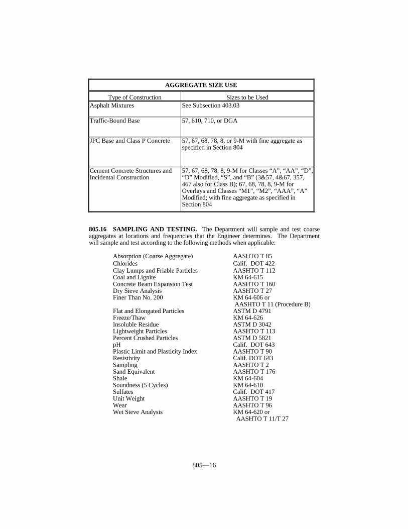
805—16
805.16 SAMPLING AND TESTING. The Department will sample and test coarseaggregates at locations and frequencies that the Engineer determines. The Departmentwill sample and test according to the following methods when applicable:
Absorption (Coarse Aggregate) AASHTO T 85Chlorides Calif. DOT 422Clay Lumps and Friable Particles AASHTO T 112Coal and Lignite KM 64-615Concrete Beam Expansion Test AASHTO T 160Dry Sieve Analysis AASHTO T 27Finer Than No. 200 KM 64-606 or
AASHTO T 11 (Procedure B)Flat and Elongated Particles ASTM D 4791Freeze/Thaw KM 64-626Insoluble Residue ASTM D 3042Lightweight Particles AASHTO T 113Percent Crushed Particles ASTM D 5821pH Calif. DOT 643Plastic Limit and Plasticity Index AASHTO T 90Resistivity Calif. DOT 643Sampling AASHTO T 2Sand Equivalent AASHTO T 176Shale KM 64-604Soundness (5 Cycles) KM 64-610Sulfates Calif. DOT 417Unit Weight AASHTO T 19Wear AASHTO T 96Wet Sieve Analysis KM 64-620 or
AASHTO T 11/T 27
AGGREGATE SIZE USE
Type of Construction Sizes to be UsedAsphalt Mixtures See Subsection 403.03
Traffic-Bound Base 57, 610, 710, or DGA
JPC Base and Class P Concrete 57, 67, 68, 78, 8, or 9-M with fine aggregate asspecified in Section 804
Cement Concrete Structures andIncidental Construction
57, 67, 68, 78, 8, 9-M for Classes “A”, “AA”, “D”,“D” Modified, “S”, and “B” (3&57, 4&67, 357,467 also for Class B); 67, 68, 78, 8, 9-M forOverlays and Classes “M1”, “M2”, “AAA”, “A”Modified; with fine aggregate as specified inSection 804

806—1
SECTION 806 ASPHALT MATERIALS
806.01 DECRIPTION. The asphalt materials section covers performance-graded (PG)binders, emulsified asphalts, cut-back emulsions, and liquid asphalt for cold-patchingmixtures. Provide the specified grade of material conforming to the requirements in thissection from suppliers listed in the Department’s List of Approved Materials. Inclusion onthe list of approved suppliers is obtained by following the guidelines of the ApprovedSupplier Certification (ASC) program contained in Kentucky Method (KM) 64-444, byfollowing the guidelines of the Emulsified Asphalt Supplier Certification (EASC) programcontained in KM 64-445, or by pretesting and approval. The Department may approveother types of asphalt materials provided they conform to the requirements of the typespecified in the contract.
806.02 SAMPLING. The Department will sample all asphalt materials according toKM 64-404.
806.03 PG BINDERS. This subsection covers the requirements and pay schedules forPG binders.
806.03.01 General Requirements. Provide PG binders conforming to AASHTO M320 except the intermediate dynamic shear will be tested at 25 °C for all material. Additionally, the material must have a minimum solubility of 99.0 percent when testedaccording to AASHTO T 44 and PG 76-22 must exhibit a minimum elastic recovery of 75percent when tested according to AASHTO T 301.
(1) If allowed to remain in place, the Department will review materials performing inthis range on a project-by-project basis to determine if removal of the material iswarranted.
(2) Results are for certification purposes only.(3) Age sample according to AASHTO T 240 and then condition and test the sample at
77 ± 1 °F. Elongate the sample to 10 cm.% Elongation Recovery = (10-X) x 10 where X is the final reading in cm afterbringing the 2 severed ends of the specimen back together.
806.03.02 Handling Requirements. Submit written instructions to the Division ofMaterials for handling requirements. Submit the Supplier’s written instructions andrequirements for the proper use and handling of the asphalt binder to the Engineer.
PG BINDER REQUIREMENTS AND PRICE ADJUSTMENT SCHEDULE
Test Specification 100% Pay 90% Pay 80% Pay 70% Pay 50% Pay(1)
Original Binder
Dynamic Shear, G*/sind 1.00 kPa Min. 1.00-0.95 0.94-0.90 0.89-0.85 0.84-0.80 < 0.80
Viscosity (2) 3 Pa·s
RTFO Residue
Mass Loss, % 1.00 Max. 1.01-1.10 1.11-1.20 1.21-1.30 1.31-1.40 > 1.40
Dynamic Shear, G*/sind 2.20 kPa Min. 2.00-2.20 1.70-1.99 1.50-1.69 1.30-1.49 < 1.30
Elastic Recovery, % (3)
(AASHTO T 301) 75 Min. =70 65-69 60-64 55-59 < 55
PAV Aging
BBR
Creep Stiffness 300 MPa Max. 300-315 316-330 331-345 346-360 > 360
m-value 0.300 Min. 0.285-0.300 0.280-0.284 0.275-0.279 0.270-0.274 < 0.270
Dynamic Shear, G*sind 5,000 kPa Max. 5,000-5,500 5,501-5,800 5,801-5,900 5,901-6,000 > 6,000
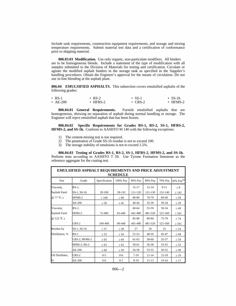
806—2
Include tank requirements, construction equipment requirements, and storage and mixingtemperature requirements. Submit material test data and a certification of conformanceprior to shipping material.
806.03.03 Modification. Use only organic, non-particulate modifiers. All bindersare to be homogeneous blends. Include a statement of the type of modification with allsamples submitted to the Division of Materials for testing and certification. Circulate oragitate the modified asphalt binders in the storage tank as specified in the Supplier’shandling procedures. Obtain the Engineer’s approval for the means of circulation. Do notuse in-line blending at the asphalt plant.
806.04 EMULSIFIED ASPHALTS. This subsection covers emulsified asphalts of thefollowing grades:
• RS-1 • RS-2 • SS-1 • SS-1h• AE-200 • HFRS-2 • CRS-2 • HFMS-2
806.04.01 General Requirements. Furnish emulsified asphalts that arehomogeneous, showing no separation of asphalt during normal handling or storage. TheEngineer will reject emulsified asphalt that has been frozen.
806.04.02 Specific Requirements for Grades RS-1, RS-2, SS-1, HFRS-2,HFMS-2, and SS-1h. Conform to AASHTO M 140 with the following exceptions:
1) The cement-mixing test is not required.2) The penetration of Grade SS-1h residue is not to exceed 100.3) The storage stability of emulsions is not to exceed 1.5%.
806.04.03 Testing of Grades RS-1, RS-2, SS-1, HFRS-2, HFMS-2, and SS-1h. Perform tests according to AASHTO T 59. Use Tyrone Formation limestone as thereference aggregate for the coating test.
EMULSIFIED ASPHALT REQUIREMENTS AND PRICE ADJUSTMENTSCHEDULE
Test Grade Specification 100% Pay 90% Pay 80% Pay 70% Pay 50% Pay(1)
Viscosity, RS-1, 15-17 12-14 9-11 ≤ 8
Saybolt Furol SS-1, SS-1h 20-100 18-110 111-120 121-130 131-140 ≥ 141
@ 77 ºF, s HFMS-2 ≥ 100 ≥ 90 80-89 70-79 60-69 ≤ 59
AE-200 ≥ 50 ≥ 45 40-44 35-39 30-34 ≤ 29
Viscosity, RS-2, 60-64 55-59 50-54 ≤ 49
Saybolt Furol HFRS-2 75-400 65-440 441-480 481-520 521-560 ≥ 561
@ 122 ºF, s 85-89 80-84 75-79 ≤ 74
CRS-2 100-400 90-440 441-480 481-520 521-560 ≥ 561
Residue by SS-1, SS-1h ≥ 57 ≥ 28 27 26 25 ≤ 24
Distillation, % RS-1 ≥ 55 ≥ 54 51-53 48-50 45-47 ≤ 44
CRS-2, HFMS-2 ≥ 65 ≥ 64 61-63 58-60 55-57 ≤ 54
HFRS-2, RS-2 ≥ 63 ≥ 62 59-61 56-58 53-55 ≤ 52
AE-200 ≥ 60 ≥ 59 56-58 53-55 50-52 ≤ 49
Oil Distillates, CRS-2 0-5 0-6 7-10 11-14 15-18 ≥ 19
% AE-200 0-6 0-7 8-10 11-13 14-16 ≥ 17
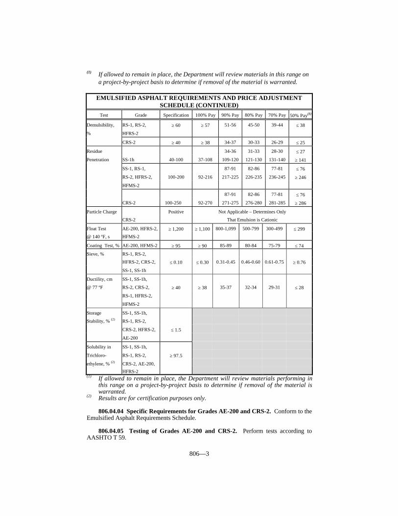
806—3
(1) If allowed to remain in place, the Department will review materials in this range ona project-by-project basis to determine if removal of the material is warranted.
EMULSIFIED ASPHALT REQUIREMENTS AND PRICE ADJUSTMENTSCHEDULE (CONTINUED)
Test Grade Specification 100% Pay 90% Pay 80% Pay 70% Pay 50% Pay(1)
Demulsibility, RS-1, RS-2, ≥ 60 ≥ 57 51-56 45-50 39-44 ≤ 38
% HFRS-2
CRS-2 ≥ 40 ≥ 38 34-37 30-33 26-29 ≤ 25
Residue 34-36 31-33 28-30 ≤ 27
Penetration SS-1h 40-100 37-108 109-120 121-130 131-140 ≥ 141
SS-1, RS-1, 87-91 82-86 77-81 ≤ 76
RS-2, HFRS-2, 100-200 92-216 217-225 226-235 236-245 ≥ 246
HFMS-2
87-91 82-86 77-81 ≤ 76
CRS-2 100-250 92-270 271-275 276-280 281-285 ≥ 286
Particle Charge Not Applicable – Determines Only
CRS-2
Positive
That Emulsion is Cationic
Float Test AE-200, HFRS-2, ≥ 1,200 ≥ 1,100 800-1,099 500-799 300-499 ≤ 299
@ 140 ºF, s HFMS-2
Coating Test, % AE-200, HFMS-2 ≥ 95 ≥ 90 85-89 80-84 75-79 ≤ 74
Sieve, % RS-1, RS-2,
HFRS-2, CRS-2, ≤ 0.10 ≤ 0.30 0.31-0.45 0.46-0.60 0.61-0.75 ≥ 0.76
SS-1, SS-1h
Ductility, cm SS-1, SS-1h,
@ 77 ºF RS-2, CRS-2, ≥ 40 ≥ 38 35-37 32-34 29-31 ≤ 28
RS-1, HFRS-2,
HFMS-2
Storage SS-1, SS-1h,
Stability, % (2) RS-1, RS-2,
CRS-2, HFRS-2, ≤ 1.5
AE-200
Solubility in SS-1, SS-1h,
Trichloro- RS-1, RS-2, ≥ 97.5
ethylene, % (2) CRS-2, AE-200,
HFRS-2(1) If allowed to remain in place, the Department will review materials performing in
this range on a project-by-project basis to determine if removal of the material iswarranted.
(2) Results are for certification purposes only.
806.04.04 Specific Requirements for Grades AE-200 and CRS-2. Conform to theEmulsified Asphalt Requirements Schedule.
806.04.05 Testing of Grades AE-200 and CRS-2. Perform tests according toAASHTO T 59.

806—4
806.05 POLYMER ASPHALT EMULSIONS (CRS-2P). These materials aredesigned to be used in seal coats and stress-absorbing membrane interlayers (SAMI). Make the polymer modification to the base asphalt before the emulsification process.Ensure that polymer-modified asphalt emulsions conform to the requirements in thePolymer Asphalt Emulsion (CRS-2P) Requirements and Price Adjustment Schedule.
POLYMER ASPHALT EMULSION (CRS-2P) REQUIREMENTS ANDPRICE ADJUSTMENT SCHEDULE
Test(1) Specification 100% Pay 90% Pay 80% Pay 70% Pay 50% Pay(2)
Viscosity @ 122 ºF, SFS(3) 50-54 45-49 40-44 ≤ 39
60-400 55-480 481-520 521-560 561-600 = 600
80-84 70-79 60-69 ≤ 59
Viscosity @ 122 ºF, SFS(4) 100-400 85-480 481-520 521-560 561-600 ≥ 601
Distillation: % Oil 0-3.0 0-5.0 5.1-8.0 8.1-10.0 10.1-12.0 ≥ 12.1
% Residue(5) ≥ 65 ≥ 63 60.0-62.9 57.0-59.9 55.0-56.9 ≤ 54.9
Sieve, % ≤ 0.1 ≤ 0.35 0.36-0.50 0.51-0.70 0.71-0.90 ≥ 0.91
Residue Penetration @ 77 ºF 80-84 75-79 70-74 ≤ 69
100-200 85-230 231-240 241-250 251-260 ≥ 261
Residue Ductility @ 39 ºF, cm ≥ 15 ≥ 13 11.0-12.9 9.0-10.9 7.0-8.9 ≤ 6.9
% Recovery @ 39 ºF (6) ≥ 55 ≥ 50 45.0-49.9 40.0-44.9 35.0-39.9 ≤ 34.9
(AASHTO T 301)
% Demulsibility:
0.8% Sodium Diocytl ≥40 ≥35 32-34 29-31 26-28 ≤ 25
Sulfosuccinate
Particle Charge Positive
Storage Stability, % (7)(8) ≤ 1.0
Solubility, % (7) ≥ 97.5
Softening Point of Residue, > 100
ºF (7) (AASHTO T 53)(1) Test according to AASHTO T 59 except where noted.(2) If allowed to remain in place, the Department will review materials performing in
this range on a project-by-project basis to determine if removal of the material iswarranted.
(3) Applies only if the residue from distillation is 72% or more.(4) Applies only if the residue from distillation is less than 72%.(5) Modify AASHTO T 59 to provide a maximum distillation temperature of 400 ± 5 °F
for at least 20 minutes.(6) Condition the sample and test the sample at 39 ± 2 °F. Elongate the sample to 10
cm. % Elongation Recovery = (10-X) x 10 where X is the final reading in cm afterbringing the two severed ends of the specimen back together.
(7) Results are for certification purposes only.(8) Provide a material that, after standing undisturbed for 24 hours, shows a uniform,
brown color throughout.
806.06 PRIMER L. Prepare Primer L by compounding a suitable solvent and waterwith a petroleum asphalt.
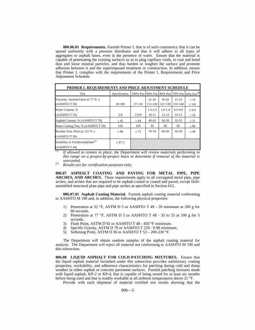
806—5
806.06.01 Requirements. Furnish Primer L that is of such consistency that it can bespread uniformly with a pressure distributor and that it will adhere to all types ofaggregates or asphalt bases, even in the presence of water. Ensure that the material iscapable of penetrating the existing surfaces so as to plug capillary voids, to coat and bonddust and loose mineral particles, and thus harden or toughen the surface and promoteadhesion between it and the superimposed treatment or construction. In addition, ensurethat Primer L complies with the requirements of the Primer L Requirements and PriceAdjustment Schedule.
PRIMER L REQUIREMENTS AND PRICE ADJUSTMENT SCHEDULE
Test Specification 100% Pay 90% Pay 80% Pay 70% Pay 50% Pay(1)
Viscosity, Saybolt-Furol @ 77 ºF, s 21-26 16-20 11-15 ≤ 10(AASHTO T 59) 30-100 27-110 111-120 121-130 131-140 ≥ 141
Water Content, % 1.5-1.9 1.0-1.4 0.5-0.9 ≤ 0.4
(AASHTO T 55) 3-8 2.0-9 10-11 12-13 14-15 ≥ 16
Asphalt Content, % (AASHTO T 78) ≥ 45 ≥ 44 40-43 36-39 32-35 ≤ 31
Stone Coating Test, % (AASHTO T 59) 100 100 95 90 85 ≤ 80
Residue Test, Float @ 122 ºF, s ≥ 80 ≥ 75 70-74 60-69 50-59 ≤ 49
(AASHTO T 50)
Solubility in Trichloroethylene(2) ≥ 97.5
(AASHTO T 44)(1) If allowed to remain in place, the Department will review materials performing in
this range on a project-by-project basis to determine if removal of the material iswarranted.
(2) Results are for certification purposes only.
806.07 ASPHALT COATING AND PAVING FOR METAL PIPE, PIPEARCHES, AND ARCHES. These requirements apply to all corrugated metal pipe, pipearches, and arches that are required to be asphalt-coated or coated and paved, except field-assembled structural plate pipe and pipe arches as specified in Section 612.
806.07.01 Asphalt Coating Material. Furnish asphalt coating material conformingto AASHTO M 190 and, in addition, the following physical properties:
1) Penetration at 32 °F, ASTM D 5 or AASHTO T 49 - 20 minimum at 200 g for60 seconds.
2) Penetration at 77 °F, ASTM D 5 or AASHTO T 49 - 35 to 55 at 100 g for 5seconds.
3) Flash Point, ASTM D 92 or AASHTO T 48 - 450 °F minimum.4) Specific Gravity, ASTM D 70 or AASHTO T 229 - 0.98 minimum.5) Softening Point, ASTM D 36 or AASHTO T 53 – 200-230 °F.
The Department will obtain random samples of the asphalt coating material foranalysis. The Department will reject all material not conforming to AASHTO M 190 andthis subsection.
806.08 LIQUID ASPHALT FOR COLD-PATCHING MIXTURES. Ensure thatthe liquid asphalt material furnished under this subsection provides satisfactory coatingproperties, workability, and adherence characteristics for patching during cold and dampweather in either asphalt or concrete pavement surfaces. Furnish patching mixtures madewith liquid asphalt, KP-2 or KP-4, that is capable of being stored for at least six monthsbefore being used and that is readily workable at all ambient temperatures above 25 °F.
Provide with each shipment of material certified test results showing that the
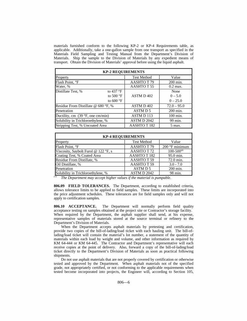
806—6
materials furnished conform to the following KP-2 or KP-4 Requirements table, asapplicable. Additionally, take a one-gallon sample from one transport as specified in theMaterials Field Sampling and Testing Manual from the Department’s Division ofMaterials. Ship the sample to the Division of Materials by any expedient means oftransport. Obtain the Division of Materials’ approval before using the liquid asphalt.
KP-2 REQUIREMENTSProperty Test Method ValueFlash Point, °F AASHTO T 79 200 min.Water, % AASHTO T 55 0.2 max.Distillate Test, % to 437 °F None to 500 °F ASTM D 402 0 – 5.0 to 600 °F 0 – 25.0
Residue From Distillate @ 680 °F, % ASTM D 402 72.0 – 95.0Penetration ASTM D 5 200 min.Ductility, cm (39 °F, one cm/min) ASTM D 113 100 min.Solubility in Trichloroethylene, % ASTM D 2042 99 min.Stripping Test, % Uncoated Area AASHTO T 182 5 max.
KP-4 REQUIREMENTSProperty Test Method ValueFlash Point, °F AASHTO T 79 200 °F minimumViscosity, Saybolt Furol @ 122 °F, s AASHTO T 72 100-500(1)
Coating Test, % Coated Area AASHTO T 182 95.0 min.Residue From Distillate, % AASHTO T 59 72.0 min.Oil Distillate, % AASHTO T 59 3.0 - 7.0Penetration ASTM D 5 200 min.Solubility in Trichloroethylene, % ASTM D 2042 98 min.
(1) The Department may accept higher values if the material is pumpable.
806.09 FIELD TOLERANCES. The Department, according to established criteria,allows tolerance limits to be applied to field samples. These limits are incorporated intothe price adjustment schedules. These tolerances are for field samples only and will notapply to certification samples.
806.10 ACCEPTANCE. The Department will normally perform field qualityacceptance testing on samples obtained at the project site or Contractor’s storage facility. When required by the Department, the asphalt supplier shall send, at his expense,representative samples of materials stored at the source terminal or refinery to theDepartment’s Division of Materials.
When the Department accepts asphalt materials by pretesting and certification,provide two copies of the bill-of-lading/load ticket with each hauling unit. The bill-of-lading/load ticket will contain the material’s lot number, a statement of the quantity ofmaterials within each load by weight and volume, and other information as required byKM 64-444 or KM 64-445. The Contractor and Department’s representative will eachreceive copies at the point of delivery. Also, forward a copy of the bill-of-lading/loadticket directly to the Department’s Division of Materials as soon as practical followingshipments.
Do not use asphalt materials that are not properly covered by certification or otherwisetested and approved by the Department. When asphalt materials not of the specifiedgrade, not appropriately certified, or not conforming to the applicable requirements whentested become incorporated into projects, the Engineer will, according to Section 105,

806—7
evaluate the work affected and require adjustment of pay quantities or corrective work asdeemed appropriate.
806.10.01 Acceptance of Non-Specification Asphalt Materials. Furnish asphaltmaterials purchased for Department work conforming to the requirements of this section. The Department will apply the following procedures only when reasonably acceptablework has been produced using the material in question, as provided in Subsection 105.04.When the use of non-specification material results in an inferior or unsatisfactory product,remove and replace the material at no expense to the Department, or at the Vendor’sexpense when materials are purchased directly by the Cabinet.
The Department may accept, at a reduced Contract price, asphalt materials not of thespecified grade, not appropriately certified, or not conforming to the applicablerequirements when check-tested after an evaluation of the work. However, the Departmentwill not consider these procedures as a means to continue accepting non-specificationmaterial.
The Department will determine the price adjustment based on the delivered cost of thematerial.
When the material is not of the specified grade or not appropriately certified, theDepartment may deduct the full cost of the material.
When the material fails to conform to the applicable requirements, the Departmentwill normally make deductions according to the pay schedules in this section. As providedin Subsection 806.09, the Department has established field tolerances for determining theacceptability of failing material at no price deduction. The Department will determine thefrequency of check-sampling and testing on pretested material. The Department will makedeductions for failing test results based on the average of two check samples representingthe material in question. When a sample fails on two or more tests, the Department mayadd the deductions, but the total deduction will not exceed 100 percent.
806.11 TIME LIMITATION ON APPROVALS. The Department will test materialsin storage at the terminal as deemed necessary. Additionally, the Department will requirethe retesting, and re-approval, of materials not incorporated into the work within onemonth (2 months for PG binders) of the shipment date.
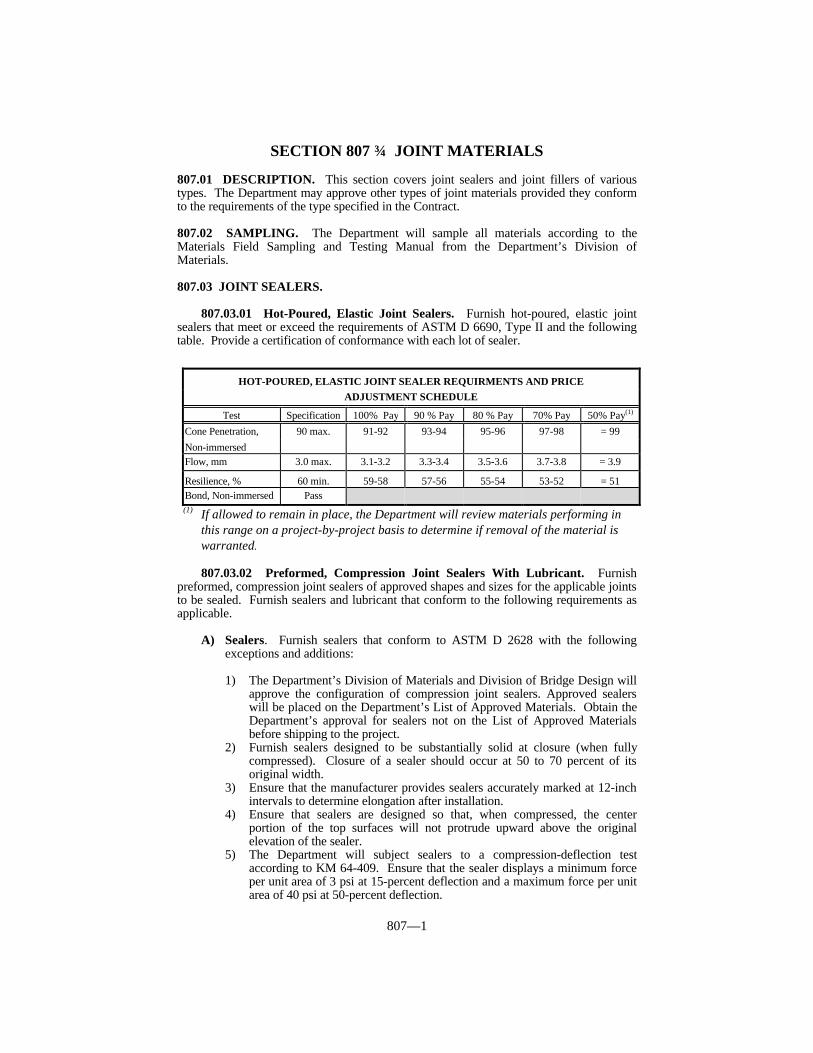
807—1
SECTION 807 JOINT MATERIALS
807.01 DESCRIPTION. This section covers joint sealers and joint fillers of varioustypes. The Department may approve other types of joint materials provided they conformto the requirements of the type specified in the Contract.
807.02 SAMPLING. The Department will sample all materials according to theMaterials Field Sampling and Testing Manual from the Department’s Division ofMaterials.
807.03 JOINT SEALERS.
807.03.01 Hot-Poured, Elastic Joint Sealers. Furnish hot-poured, elastic jointsealers that meet or exceed the requirements of ASTM D 6690, Type II and the followingtable. Provide a certification of conformance with each lot of sealer.
(1) If allowed to remain in place, the Department will review materials performing inthis range on a project-by-project basis to determine if removal of the material iswarranted.
807.03.02 Preformed, Compression Joint Sealers With Lubricant. Furnishpreformed, compression joint sealers of approved shapes and sizes for the applicable jointsto be sealed. Furnish sealers and lubricant that conform to the following requirements asapplicable.
A) Sealers. Furnish sealers that conform to ASTM D 2628 with the followingexceptions and additions: 1) The Department’s Division of Materials and Division of Bridge Design will
approve the configuration of compression joint sealers. Approved sealerswill be placed on the Department’s List of Approved Materials. Obtain theDepartment’s approval for sealers not on the List of Approved Materialsbefore shipping to the project.
2) Furnish sealers designed to be substantially solid at closure (when fullycompressed). Closure of a sealer should occur at 50 to 70 percent of itsoriginal width.
3) Ensure that the manufacturer provides sealers accurately marked at 12-inchintervals to determine elongation after installation.
4) Ensure that sealers are designed so that, when compressed, the centerportion of the top surfaces will not protrude upward above the originalelevation of the sealer.
5) The Department will subject sealers to a compression-deflection testaccording to KM 64-409. Ensure that the sealer displays a minimum forceper unit area of 3 psi at 15-percent deflection and a maximum force per unitarea of 40 psi at 50-percent deflection.
HOT-POURED, ELASTIC JOINT SEALER REQUIRMENTS AND PRICEADJUSTMENT SCHEDULE
Test Specification 100% Pay 90 % Pay 80 % Pay 70% Pay 50% Pay(1)
Cone Penetration, 90 max. 91-92 93-94 95-96 97-98 = 99Non-immersedFlow, mm 3.0 max. 3.1-3.2 3.3-3.4 3.5-3.6 3.7-3.8 = 3.9
Resilience, % 60 min. 59-58 57-56 55-54 53-52 = 51Bond, Non-immersed Pass

807—2
6) Ensure that the sealers used in JPC pavement comply with the applicableStandard Drawings.
7) Ensure that the uncompressed depth of all sealers is at least equal to theuncompressed sealer width, unless the design of the sealer prevents twistingor misalignment of the sealer during or after installation.
8) Ensure each lot number is accompanied by a certification statingconformance with this Subsection.
B) Lubricant. As recommended by the sealer manufacturer, provide lubricant thatis compatible with the sealer, concrete, steel and meets the following criteria:
1) Concrete Pavements. Obtain certification from the manufacturer stating thematerial conforms to ASTM D 2835.
2) Bridges. Obtain certification from the manufacturer stating the materialconforms to ASTM D 4070.
807.03.03 Preformed, Expansion Joint Strip Seals With Lubricant Adhesive.Furnish preformed, expansion joint strip sealers of approved design for the applicablejoints to be sealed. Furnish sealers and lubricant adhesives that conform to thefollowing requirements as applicable.
A) Sealers. Furnish sealers that conform to ASTM D 5973 with the followingexceptions and additions:
1) The Department’s Division of Materials and Division of Bridge Design will
approve the design of the expansion joint strip sealers. Approved sealerswill be placed on the Department’s List of Approved Materials. Obtain theDepartment’s approval for sealers not on the List of Approved Materialsbefore shipping to the project.
2) Ensure that the manufacturer provides sealers accurately marked at 12-inchintervals to determine elongation after installation.
3) Ensure that the sizes of sealers used in JPC pavement comply with theapplicable Standard Drawings.
4) Ensure each lot number is accompanied by a certification statingconformance with this Subsection.
B) Lubricant Adhesive. As recommended by the sealer manufacturer, providelubricant adhesive that is compatible with the sealer, concrete, and steel. Obtaincertification from the manufacturer stating the material conforms to ASTM D 4070.
807.03.04 Joint Sealer for Rigid Pipe.
A) Asphalt Mastic. Furnish asphalt mastic joint sealing material consisting of asmooth, uniform mixture of asphalt material, solvent, and filler. Use filler thatconsists essentially of cellulose fiber. Ensure that the mixture is applicable, bymeans of a trowel or caulking gun, without pulling or drawing, and does not sagor flow when applied to metal, concrete, or vitrified clay surfaces. Furnish acompound capable of withstanding freezing and not exhibiting any tendency toseparate or otherwise deteriorate while in storage. Ensure each lot number isaccompanied by a certification stating conformance with this Subsection.
When tested according to KM 64-416, ensure that the compound sets to atough, plastic coating and does not shrink, crack, or loosen from the surface. Inaddition, furnish material conforming to the following table:

807—3
B) Butyl Rubber Sealants. Furnish butyl rubber sealants conforming to therequirements in AASHTO M 198, Section 6.2. Ensure each lot number isaccompanied by a certification of conformance.
C) Rubber Gaskets. Furnish rubber gaskets conforming to the requirements inAASHTO M 315, Section 6.1. Ensure each lot number is accompanied by acertification of conformance.
807.03.05 Silicone Rubber Sealants. Provide material conforming to the followingrequirements and tables.
A) Non-Sag and Self-Leveling Silicone Sealant. Furnish sealant in a one-partsilicone formulation which does not require a primer for bonding to concrete. Use a compound that is compatible with the surface to which it is applied. Donot use acid-cure sealants on concrete. Apply the sealant with a pressureapplicator that forces it into the joint. Ensure self-leveling silicone, which issuitable for joints of one-inch width or less, exhibits a smooth, level surface withno indication of bubbling. Ensure each lot number is accomapnied by acertification stating conformance to this Subsection. Provide material thatconforms to ASTM D 5893 with the following exceptions and additions:
1) Non-sag tensile stress and elongation samples will be cured for 7 days. 2) Non-sag durometer hardness will be determined at 73 ± 4 °F. 3) The non-sag, tack-free time requirement is 20 – 90 minutes. 4) The self-leveling relative tack-free time, according to ASTM C 679, will be
a maximum of 60 minutes.
B) Rapid-Cure Silicone Sealant. Use sealant that is: (1) furnished as a two-part,rapid-cure, cold-applied, ultra-low-modulus, self-leveling, 100-percent siliconerubber sealant; (2) flexible over a wide temperature range; and (3) suitable foruse in concrete-to-concrete, concrete-to-steel, and steel-to-steel joints. Providematerial meeting the requirements of the following table. Ensure each lotnumber is accompanied by a certification stating conformance with thisSubsection.
C) Accessory Items. Use a closed-cell, polyethylene foam, back-up rod that iscompatible with the sealant. Ensure no bond or reaction occurs between theback-up rod and sealant.
D) Approvals. Ensure that each lot of sealant is delivered in containers plainlymarked with the manufacturer’s name or trademark and a lot number. Ensurethat the manufacturer furnishes certified test results of each lot of joint sealantshipped to each project. The Department does not require tests for ozone and UVresistance, or movement capability and adhesion, on every lot, but ensure thatevery lot is accompanied by certified results of the latest tests performed. Ensurethat the manufacturer indicates the date of shipment on each lot. Do not usematerial after six months from the date of shipment from the manufacturerwithout first having the material sampled and tested. The Department will takeroutine check samples of silicone sealant during application and test it to verify
ASPHALT MASTIC REQUIREMENTSTest Test Method Specification
Grease Cone Penetration (Unworked), 150 g ASTM D 217 175 - 250Weight per Gallon, lbs AASHTO T 229 9.75 min.Non-Volatile, % KM 64-415 75 min.Ash, % AASHTO T 111 25 - 45
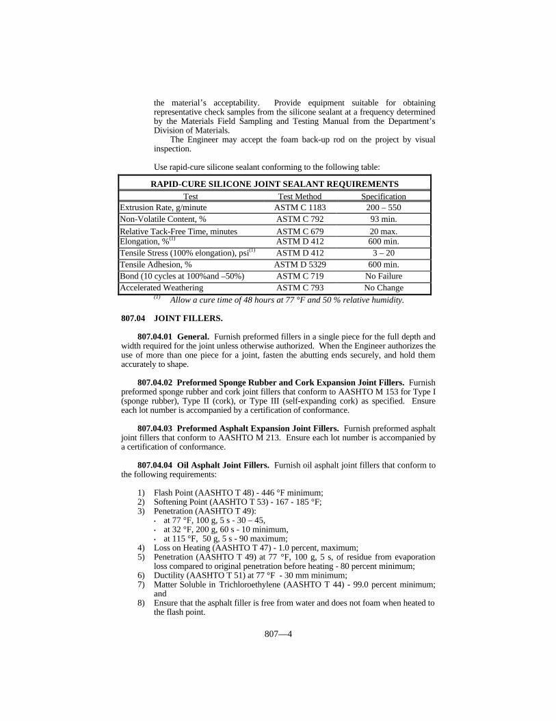
807—4
the material’s acceptability. Provide equipment suitable for obtainingrepresentative check samples from the silicone sealant at a frequency determinedby the Materials Field Sampling and Testing Manual from the Department’sDivision of Materials.
The Engineer may accept the foam back-up rod on the project by visualinspection.
Use rapid-cure silicone sealant conforming to the following table:
(1) Allow a cure time of 48 hours at 77 °F and 50 % relative humidity.
807.04 JOINT FILLERS.
807.04.01 General. Furnish preformed fillers in a single piece for the full depth andwidth required for the joint unless otherwise authorized. When the Engineer authorizes theuse of more than one piece for a joint, fasten the abutting ends securely, and hold themaccurately to shape.
807.04.02 Preformed Sponge Rubber and Cork Expansion Joint Fillers. Furnishpreformed sponge rubber and cork joint fillers that conform to AASHTO M 153 for Type I(sponge rubber), Type II (cork), or Type III (self-expanding cork) as specified. Ensureeach lot number is accompanied by a certification of conformance.
807.04.03 Preformed Asphalt Expansion Joint Fillers. Furnish preformed asphaltjoint fillers that conform to AASHTO M 213. Ensure each lot number is accompanied bya certification of conformance.
807.04.04 Oil Asphalt Joint Fillers. Furnish oil asphalt joint fillers that conform tothe following requirements:
1) Flash Point (AASHTO T 48) - 446 °F minimum;2) Softening Point (AASHTO T 53) - 167 - 185 °F;3) Penetration (AASHTO T 49):
• at 77 °F, 100 g, 5 s - 30 – 45,• at 32 °F, 200 g, 60 s - 10 minimum,• at 115 °F, 50 g, 5 s - 90 maximum;
4) Loss on Heating (AASHTO T 47) - 1.0 percent, maximum;5) Penetration (AASHTO T 49) at 77 °F, 100 g, 5 s, of residue from evaporation
loss compared to original penetration before heating - 80 percent minimum;6) Ductility (AASHTO T 51) at 77 °F - 30 mm minimum;7) Matter Soluble in Trichloroethylene (AASHTO T 44) - 99.0 percent minimum;
and8) Ensure that the asphalt filler is free from water and does not foam when heated to
the flash point.
RAPID-CURE SILICONE JOINT SEALANT REQUIREMENTSTest Test Method Specification
Extrusion Rate, g/minute ASTM C 1183 200 – 550Non-Volatile Content, % ASTM C 792 93 min.Relative Tack-Free Time, minutes ASTM C 679 20 max.Elongation, %(1) ASTM D 412 600 min.Tensile Stress (100% elongation), psi(1) ASTM D 412 3 – 20Tensile Adhesion, % ASTM D 5329 600 min.Bond (10 cycles at 100%and –50%) ASTM C 719 No FailureAccelerated Weathering ASTM C 793 No Change
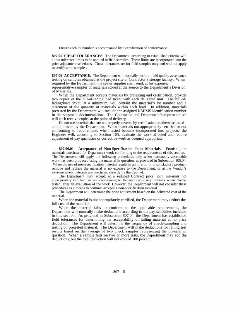
807—5
Ensure each lot number is accompanied by a certification of conformance.
807.05 FIELD TOLERANCES. The Department, according to established criteria, willallow tolerance limits to be applied to field samples. These limits are incorporated into theprice adjustment schedules. These tolerances are for field samples only and will not applyto certification samples.
807.06 ACCEPTANCE. The Department will normally perform field quality acceptancetesting on samples obtained at the project site or Contractor’s storage facility. Whenrequired by the Department, the sealer supplier shall send, at his expense,representative samples of materials stored at the source to the Department’s Divisionof Materials.
When the Department accepts materials by pretesting and certification, providetwo copies of the bill-of-lading/load ticket with each delivered unit. The bill-of-lading/load ticket, at a minimum, will contain the material’s lot number and astatement of the quantity of materials within each load. In addition, materialspretested by the Department will include the assigned KMIMS identification numberin the shipment documentation. The Contractor and Department’s representativewill each receive copies at the point of delivery.
Do not use materials that are not properly covered by certification or otherwise testedand approved by the Department. When materials not appropriately certified or notconforming to requirements when tested become incorporated into projects, theEngineer will, according to Section 105, evaluate the work affected and requireadjustment of pay quantities or corrective work as deemed appropriate.
807.06.01 Acceptance of Non-Specification Joint Materials. Furnish jointmaterials purchased for Department work conforming to the requirements of this section. The Department will apply the following procedures only when reasonably acceptablework has been produced using the material in question, as provided in Subsection 105.04. When the use of non-specification material results in an inferior or unsatisfactory product,remove and replace the material at no expense to the Department, or at the Vendor’sexpense when materials are purchased directly by the Cabinet.
The Department may accept, at a reduced Contract price, joint materials notappropriately certified, or not conforming to the applicable requirements when check-tested, after an evaluation of the work. However, the Department will not consider theseprocedures as a means to continue accepting non-specification material.
The Department will determine the price adjustment based on the delivered cost of thematerial.
When the material is not appropriately certified, the Department may deduct thefull cost of the material.
When the material fails to conform to the applicable requirements, theDepartment will normally make deductions according to the pay schedules includedin this section. As provided in Subsection 807.04, the Department has establishedfield tolerances for determining the acceptability of failing material at no pricededuction. The Department will determine the frequency of check-sampling andtesting on pretested material. The Department will make deductions for failing testresults based on the average of two check samples representing the material inquestion. When a sample fails on two or more tests, the Department may add thedeductions, but the total deduction will not exceed 100 percent.
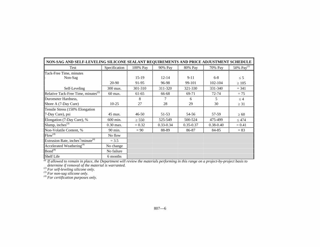
807—6
(1) If allowed to remain in place, the Department will review the materials performing in this range on a project-by-project basis to determine if removal of the material is warranted.
(2) For self-leveling silicone only. (3) For non-sag silicone only.(4) For certification purposes only.
NON-SAG AND SELF-LEVELING SILICONE SEALANT REQUIREMENTS AND PRICE ADJUSTMENT SCHEDULETest Specification 100% Pay 90% Pay 80% Pay 70% Pay 50% Pay(1)
Tack-Free Time, minutes Non-Sag 15-19 12-14 9-11 6-8 ≤ 5
20-90 91-95 96-98 99-101 102-104 ≥ 105Self-Leveling 300 max. 301-310 311-320 321-330 331-340 = 341
Relative Tack-Free Time, minutes(2) 60 max. 61-65 66-68 69-71 72-74 = 75Durometer Hardness, 8 7 6 5 ≤ 4Shore A (7-Day Cure) 10-25 27 28 29 30 ≥ 31Tensile Stress (150% Elongation7-Day Cure), psi 45 max. 46-50 51-53 54-56 57-59 ≥ 60Elongation (7-Day Cure), % 600 min. ≥ 550 525-549 500-524 475-499 ≤ 474Slump, inches(3) 0.30 max. = 0.32 0.33-0.34 0.35-0.37 0.38-0.40 = 0.41Non-Volatile Content, % 90 min. = 90 88-89 86-87 84-85 = 83Flow(4) No flowExtrusion Rate, inches3/minute(4) = 3.5Accelerated Weathering(4) No changeBond(4) No failureShelf Life 6 months

807—7
807.07 TIME LIMITATION ON APPROVALS. The Department will test materialsin storage at the Contractor’s site as deemed necessary. Additionally, the Department willrequire the retesting, and re-approval, of materials not incorporated into the workaccording to the time limitations specified in the Materials Field Sampling and TestingManual from the Department’s Division of Materials.
808—1
SECTION 808 WATERPROOFING MATERIALS
808.01 DESCRIPTION. This section covers materials for use in waterproofing. TheDepartment may approve other types of waterproofing materials provided they conform tothe requirements of the type Contract specifies.
808.02 SAMPLING. The Department will sample all materials according to theMaterials Field Sampling and Testing Manual from the Department’s Division ofMaterials.
808.03 ASPHALT MOP COAT. Furnish material that conforms to ASTM D 449, asspecified in the Asphalt Mop Coat Requirements and Price Adjustment Schedule. UseType I, II, or III material as the Contract specifies.
808.04 ASPHALT PRIMER. Furnish material that conforms to ASTM D 41 andensure the supplier provides certification of conformance.
808.05 FIBERGLASS WATERPROOFING MEMBRANE. Furnish a fiberglasswaterproofing membrane that is a one-step waterproofing and reflective-crack suppressionsystem for bridge decks. The one-step system is comprised of a high strength, fiberglass-reinforced, factory coating with an asphalt polymer and a strongly bonding contactadhesive on one side that bonds to the surface being treated. Ensure the supplier providescertification that the fiberglass waterproofing membrane conforms to the following table:
808.06 LAYERED, FIBER-REINFORCED WATERPROOFING MEMBRANE.Furnish a plastic film and mesh-reinforced mastic membrane for sealing open expansionjoints, concrete expansion joints, cracked culverts, or for waterproofing in backfillsituations. Ensure the supplier provides certification that this material conforms to ASTMC 877, Type II, excluding the steel straps.
808.07 FIELD TOLERANCES. The Department, according to established criteria,will allow tolerance limits to be applied to field samples. These limits are incorporatedinto the price adjustment schedules. These tolerances are for field samples only.
808.08 ACCEPTANCE. The Department will normally perform field quality acceptancetesting on samples obtained at the project site of Contractor’s storage facility. Whenrequired by the Department, the supplier shall send, at his expense, representative samplesof materials stored at the source to the Department’s Division of Materials.
When the Department accepts materials by pretesting and certification, provide twocopies of the bill-of-lading/load ticket with each delivered unit. The bill-of-lading/loadticket, at a minimum, will contain the material’s lot number and a statement of thequantity of materials within each load. In addition, materials pretested by the Departmentwill include the assigned KMIMS identification number in the shipment documentation. The Contractor and Department’s representative will each receive copies at the point ofdelivery.
Do not use materials that are not properly covered by certification or otherwise tested
FIBERGLASS WATERPROOFING MEMBRANE REQUIREMENTSProperty Test Method Specification
Tensile Strength, lbf/in ASTM D 146 44 min.(longitudinal and transverse)Pliability ASTM D 146 PassMoisture, % ASTM D 146 1 max.Permeability, perms ASTM E 96 10 max.
808—2
and approved by the Department. When materials not appropriately certified or notconforming to the applicable requirements when tested become incorporated into projects,the Engineer will, according to Section 105, evaluate the work affected and requireadjustment of pay quantities of corrective work as deemed appropriate.
808.09 ACCEPTANCE OF NON-SPECIFICATION WATERPROOFINGMATERIALS. Furnish waterproofing materials purchased for Department workconforming to the requirements of this section. The Department will apply the followingprocedures only when reasonably acceptable work has been produced using the material inquestion, as provided in Subsection 105.04. When the use of non-specification materialresults in an inferior or unsatisfactory product, remove and replace the material at noexpense to the Department, or at the Vendor’s expense when materials are purchaseddirectly by the Cabinet.
The Department may accept, at a reduced Contract price, waterproofing materials notappropriately certified, or not conforming to the applicable requirements when check-tested, after an evaluation of the work. However, the Department will not consider theseprocedures as a means to continue accepting non-specification material.
The Department will determine the price adjustment based on the delivered cost of thematerial.
When the material is not appropriately certified, the Department may deduct the fullcost of the material.
When the material fails to conform to the applicable requirements, the Departmentwill normally make deductions according to the pay schedules included in this section. Asprovided in Section 808.07, the Department has established field tolerances fordetermining the acceptability of failing material at no price deduction. The Departmentwill determine the frequency of check-sampling and testing on pretested material. TheDepartment will make deductions for failing test results based on the average of 2 checksamples representing the material in question. When a sample fails on two or more tests,the Department may add the deductions, but the total deduction will not exceed 100percent.
808.10 TIME LIMITATION ON APPROVALS. The Department will test materialsin storage at the Contractor’s site as deemed necessary. Additionally, the Department willrequire the retesting, and re-approval, of materials not incorporated into the workaccording to the time limitations specified in the Materials Field Sampling and TestingManual from the Department’s Division of Materials.
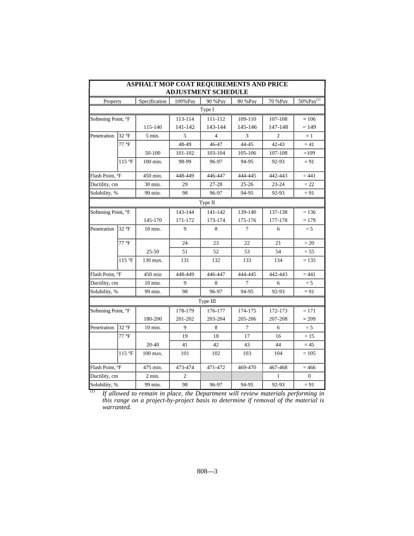
808—3
ASPHALT MOP COAT REQUIREMENTS AND PRICEADJUSTMENT SCHEDULE
Property Specification 100%Pay 90 %Pay 80 %Pay 70 %Pay 50%Pay(1)
Type I
Softening Point, °F 113-114 111-112 109-110 107-108 = 106115-140 141-142 143-144 145-146 147-148 = 149
Penetration 32 °F 5 min. 5 4 3 2 = 1
48-49 46-47 44-45 42-43 = 41
77 °F
50-100 101-102 103-104 105-106 107-108 =109
115 °F 100 min. 98-99 96-97 94-95 92-93 = 91
Flash Point, °F 450 min. 448-449 446-447 444-445 442-443 = 441
Ductility, cm 30 min. 29 27-28 25-26 23-24 = 22
Solubility, % 99 min. 98 96-97 94-95 92-93 = 91
Type II
Softening Point, °F 143-144 141-142 139-140 137-138 = 136145-170 171-172 173-174 175-176 177-178 = 179
Penetration
32 °F 10 min. 9 8 7 6 = 5
24 23 22 21 = 20
77 °F
25-50 51 52 53 54 = 55
115 °F 130 max. 131 132 133 134 = 135
Flash Point, °F 450 min 448-449 446-447 444-445 442-443 = 441
Ductility, cm 10 min. 9 8 7 6 = 5
Solubility, % 99 min. 98 96-97 94-95 92-93 = 91
Type III
Softening Point, °F 178-179 176-177 174-175 172-173 = 171180-200 201-202 203-204 205-206 207-208 = 209
Penetration 32 °F 10 min. 9 8 7 6 = 5
19 18 17 16 = 15
77 °F
20-40 41 42 43 44 = 45
115 °F 100 max. 101 102 103 104 = 105
Flash Point, °F 475 min. 473-474 471-472 469-470 467-468 = 466
Ductility, cm 2 min. 2 1 0
Solubility, % 99 min. 98 96-97 94-95 92-93 = 91(1) If allowed to remain in place, the Department will review materials performing in
this range on a project-by-project basis to determine if removal of the material iswarranted.

809—1
SECTION 809 STRUCTURAL PLATES FOR PIPES, PIPEARCHES, AND ARCHES
809.01 CORRUGATED STEEL STRUCTURAL PLATE AND ACCESSORIES. Conform to AASHTO M 167. Coat with asphalt material conforming to Subsection806.11. The Department will sample and test the material according to its currentpractices.
809.02 ALUMINUM ALLOY STRUCTURAL PLATE AND ACCESSORIES. Conform to AASHTO M 219. The Department will sample and test the materialaccording to its current practices.
810—1
SECTION 810 PIPE AND PIPE ARCHES
810.01 DESCRIPTION. This section covers the various types of pipe and pipe archesfor use on highway projects.
810.02 APPROVAL. Select pipe or pipe arches supplied by a producer that is listed onthe List of Approved Materials. All producers of pipe and pipe arches must conform toKM 114. These requirements may be obtained from the Division of Materials.
810.03 REINFORCED CONCRETE PIPE.
810.03.01 Pipe Class.
A) Circular. Furnish circular reinforced concrete pipe conforming to AASHTO M170 for Class I, Class II, Class III, Class IV, and Class V. Furnish a D-load pipeconforming to AASHTO M 242 when specified in the Contract.
B) Elliptical. Furnish horizontal and vertical elliptical reinforced concrete pipeconforming to AASHTO M 207 for Class HE-A, Class HE-I, Class HE-II, ClassHE-III, Class HE-IV, Class VE-V, Class VE-VI, Class V-II, Class VE-III, andClass VE-IV.
C) Arch. Furnish reinforced concrete pipe arch conforming to AASHTO M 206 forClass A-II, Class A-III, and Class A-IV.
810.03.02 Aggregates. Conform to Section 804 and 805.
810.03.03 Cement. Use any type conforming to Section 801.
810.03.04 Concrete. Submit concrete mix designs to Central Office Materials.
810.03.05 Extra Protection. Furnish concrete pipe with extra protection to inhibitcorrosion when required by the Standard Drawings for culvert pipe, storm sewer pipe, andentrance pipe. Furnish concrete pipe with extra protection for all other types of pipe whenspecified in the Contract. Use reinforced concrete pipe conforming to Subsection810.03.01 A) for Classes III, IV, and V; Subsection 810.03.01 B) for Classes HE-II, HE-III, HE-IV, VE-II, VE-III, and VE-IV; and Subsection 810.03.01 C) for Classes A-II, A-III, and A-IV. Use concrete having a minimum compressive strength of 6,000 psi at thetime of acceptance. Use Wall B or Wall C as necessary.
When using one line of reinforcement, place it 1/2 of the shell thickness from theinner surface of the pipe. When using 2 lines of reinforcement, place each line so that thenominal protective covering of concrete is one inch from the outer surface of the pipe and 13/4 inches from the inner surface. The Department will allow a variation tolerance of± 1/2 inch with a minimum protective covering of one inch from the inner surface in allcases.
810.03.06 Identification and Markings. Mark pipe sections according to AASHTOM 170 or M 207 as applicable for identification. Additionally, mark “EP” on each sectionof pipe manufactured by the extra protection requirements. When the manufacturer hasmore than one plant, include the plant letter assigned by the Division of Materials after thedate of manufacture as follows:
L-LouisvilleN-LondonProvide shipment approval form containing the following information:
1) Project Number and county.2) Name of Contractor.3) The size, class, and quantity of pipe shipped.
810—2
4) The dates of manufacture of the pipe.5) A signed statement that the pipe is from a tested and approved lot.
The Department will not require the certification on the shipment approval form to benotarized. The Department will not require the information under “Pipe Data” on theapproval form when the manufacturer’s shipment ticket is attached and contains thenecessary information.
The Engineer will check pipe joints to determine if the information on the approvalform or shipping ticket corresponds to the pipe actually received. Correct all discrepanciesbefore using pipe.
810.03.07 Defects. The Department will reject pipe for any of the following reasons.
1) Exposed steel in walls, fractures or cracks passing through the wall, except for asingle end crack that does not exceed the depth of the joint.
2) Defects that indicate imperfect proportioning, mixing, or molding.3) Surface defects indicating honey-combed or open texture.4) Damaged or cracked ends that prevent a satisfactory joint.5) A continuous crack, regardless of its position in the wall of the pipe, having a
surface width of 0.01-inch or more and extending 12 inches or more.
810.04 CORRUGATED METAL PIPE.
810.04.01 Coating Requirements. Use asphalt coating and paving as extraprotection to inhibit corrosion for the pH values shown on the Standard Drawings forculvert pipe, storm sewer pipe and entrance pipe. Coat and pave sanitary sewer pipe andall other pipe when specified in the Contract. Coat and pave the invert according toSubsection 806.11. Use asphalt material conforming to Subsection 806.11. Coat andpave the pipe according to AASHTO M 190.
Use polymer precoated galvanized corrugate metal pipe when the pH is greater than 9or less than 5 according to the Standard Drawings. Manufacture according to AASHTOM 245, with a minimum grade of 10/10. Fabricate the sheets into pipe sections accordingto AASHTO M 36.
The Department will allow exceptions for coating on storm sewer pipe and entrancepipe as specified in the Standard Drawings.
810.04.02 Inlet and Outlet Requirements. Finish all pipe ends in a neat manner toallow safe handling and contact with the pipe. Unless the pipe is asphalt coated, paint theends with inorganic zinc primer. When using 14 gauge or thinner sheets to fabricatehelical lockseam or welded seam pipe, reroll the inlet and outlet end with at least 4complete corrugations. Match mark all pipe that is 54 inches or larger in diameter.
810.04.03 Pipe Type. Furnish steel pipe conforming to AASHTO M 36 andaluminum alloy pipe conforming to AASHTO M 196 for types shown below:
A) Circular. Type I or Type IR.B) Arch. Type II or Type IIR.C) Underdrain. Type III.
810.04.04 Coupling Bands. Furnish bands with annular or helical corrugationconforming to AASHTO M 36 and the requirements of 701.03.05.
810.04.05 Slotted Drain Pipe. Furnish pipe according to Subsection 810.04.03 A)with the addition of a grate assembly to provide openings in the top of the pipe as specifiedin the Plans. Apply asphalt coating after slotted drain pipe is fabricated. Provide materialfor slotted drain pipe from a supplier on the Department’s List of Approved Materials. Furnish one of the following types of grate assemblies:
810—3
A) Type I. The grate assembly is fabricated from structural steel, galvanizedaccording to AASHTO M 111 after fabrication, and forms a continuous drainslot when 2 or more joints of pipe are banded together.
B) Type II. The grate assembly is fabricated from 14 gauge steel, galvanizedaccording to AASHTO M 218, and laterally supported by a minimum of onefoot, measured laterally, of concrete on each side.
810.04.06 Defects. The Department will reject pipe for any of the following reasons.
1) Variation from centerline.2) Elliptical shape in pipe intended to be round.3) Dents or bends in the metal.4) Lack of rigidity.5) Low asphalt coating thickness on coated pipe.6) Cracks or lack of coating adhesion on coated pipe.7) Insufficient coating to provide a smooth level flow line on fully lined pipe and
pipe with a paved invert.8) Paved sections with less than 25 percent coverage of the pipe circumference.
810.03.07 Concrete. Submit Concrete Mix Design to the Central Office Materials.
810.05 SMOOTH METAL PIPE.
810.05.01 Cast Iron Pressure Pipe. Conform to ASTM A 377.
810.05.02 Welded and Seamless Steel Pipe for Bridge Floor Drains. Furnish 6-inch diameter round standard weight pipe conforming to ASTM A 53, ASTM A 500, orASTM A 501 with a minimum wall thickness of 0.28 inches.
810.05.03 Black and Hot-Dipped Galvanized Welded and Seamless Steel Pipefor Ordinary Uses. Furnish pipe conforming to ASTM A 53 of the size and weightspecified in the Contract. The Department will allow plain or threaded end finish.
810.05.04 Aluminum Alloy Extruded Structural Pipe. For pipe with internalconnections, conform to ASTM B 221, Schedule 40, Alloy 6063-T52 for railing andASTM B210, Schedule 40, Alloy 6063-T832 for posts.
For pipe with welded connections, conform to ASTM B221, Schedule 40, Alloy6061-T6 or ASTM B210, Schedule 40, Alloy 6061-T6.
810.06 Thermoplastic Pipe.
810.06.01 Polyvinyl Chloride (PVC) Pipe.
A) Pipe Underdrain. Furnish perforated pipe for underdrains conforming toAASHTO M 304. Ensure all fittings and pipe are made from the same basematerial. Submit a manufacturer’s certification that the pipe conforms toAASHTO M 304 to the Division of Materials annually. Use integral bell andspigot type joints with elastomeric seal joints and smooth inner walls.
B) Culvert and Entrance Pipe. Furnish pipe and pipe fittings conforming toAASHTO M 304. Manufacture from low filler PVC plastic having a minimumASTM 1784 cell classification of 12454. Use pipe fittings furnished by the pipemanufacturer.
C) Sliplining Pipe (Rehabilitation). Furnish pipe conforming to ASTM F949.Manufacture from low filler PVC plastic having a minimum ASTM 1784 cellclassification of 12454B or 12454C. Use integral bell and spigot type joints witha STAB-JOINT bell coupler filling flush with the outer wall surface.
810—4
810.06.02 Corrugated High Density Polyethylene (HDPE) Pipe.
A) Pipe Underdrain. Furnish perforated pipe for underdrains conforming toAASHTO M 252. Use only Type S for edge drain outlet pipe. Use caps, bands,and other fittings that are of the same material as the pipe. Submit amanufacturer’s certification that the pipe conforms to AASHTO M 252 to theDivision of Materials annually. Use a length that minimizes the number of jointsin a run or line and facilitates shipment, handling, and installation. Use snap-in-place bands or a split band taped in place with polyethylene tape for pipe-to-pipeconnections as the Engineer directs. Cap remote ends with a snap-in-place cap. Use non-perforated pipe when specified in the Contract or when the Engineerdirects.
B) Culvert Pipe, Storm Sewer, and Entrance Pipe. Furnish pipe and pipe fittingsconforming to AASHTO M 294, Type S or D. Use pipe fittings furnished by thepipe manufacturer. Use pipe couplings conforming to AASHTO M 294 and thatare Department approved. When corrugations are spiral, use match marks,specially cut ends, or other acceptable methods to facilitate alignment of thecorrugations at connections. Provide a minimum gap between adjacent sectionsof pipe. Submit a manufacturer’s certification that the pipe conforms to resinrequirements of AASHTO M 294 to the Division of Materials annually. Providecertification from the manufacturer with each shipment that the pipe conforms toAASHTO M 294. Use only Department approved pipe. The Department willperform all sampling and testing deemed necessary, either at the plant or on theproject.
811—1
SECTION 811 STEEL REINFORCEMENT
811.01 CLASSIFICATION AND CONDITION. This specification covers bars,welded steel wire fabrics, bar mats, steel wire, prestressing strands, and load transferassemblies. Ensure that these materials, when incorporated into the work, are reasonablyfree from dirt, paint, oil, grease, loose-thick rust, or other foreign substance and, whendeemed necessary, are cleaned to the satisfaction of the Engineer. The Department will notrequire cleaning when these materials exhibit tight, thin, or powdery rust.
Reject reinforcement rusted sufficiently to cause it to fail specified physical propertiesor prestressing strands displaying pits visible to the naked eye.
811.02 BARS. For all bar reinforcement use Grade 60 deformed bars except asindicated for the following items:
A) JPC Pavement Tie Bars, Paved Ditches, Steps, Flume Inlets, Integral Curb,Right-of-Way Markers, Transverse Bars for Bar Mats, Piles, Cribbing, SmallDrainage Structures, Pipe Headwalls, or Manhole Tops. Use Grade 40, 50, or 60deformed bars.
B) Steel Piling Encasement and Spiral Reinforcement for Precast (non-prestressed)Piling. Use Grade 40, 50 or 60 plain or deformed bars.
C) Spiral Reinforcement (excluding piles). Use Grade 60 deformed or plain bars.
811.02.01 Requirements. Furnish bar reinforcement for bridges, cast-in-placeculverts, and cast-in-place retaining walls that conform to ASTM A 615 (billet) or ASTMA 616 (rail). Do not weld rail steel bar reinforcement. The Engineer will accept rail steelbar reinforcement in straight lengths only. Do not use rail steel bar reinforcement wherefield bending is allowed or required.
Furnish bar reinforcement for other uses that conform to either ASTM A 615 (billet),ASTM A 616 (rail), or ASTM A 617 (axle).
811.02.02 Testing and Acceptance. Identify all shipments of steel reinforcement bythe producer’s heat or test identification numbers. Obtain bar reinforcement frommanufacturers included on the Department’s List of Approved Materials. To be includedon this list, Fabricators shall conform to KM 64-101.
811.03 HOOK BOLTS AND ANCHOR BOLTS. Conform to the design anddimensions provided in the Standard Drawings. Furnish hook tie-bolts that, whenassembled as a unit, are capable of sustaining an axial load of 14,000 pounds or greater.
811.04 WELDED STEEL WIRE FABRIC (WWF). Conform to AASHTO M 55.
811.05 WELDED DEFORMED STEEL WIRE FABRIC. Conform to AASHTO M221.
811.06 BAR MATS. Conform to ASTM A 184 and fabricate by welding deformedGrade 60 billet bars.
811.07 STEEL WIRE. Conform to AASHTO M 32.
811.08 PRESTRESSING STRANDS. Ensure that Uncoated Seven-Wire StressRelieved Strand for Prestressed Concrete conforms to AASHTO M 203, Grade 270 or lowrelaxation strand Grade 270 as specified.
811.09 LOAD TRANSFER ASSEMBLIES (CONTRACTION ANDEXPANSION). The Department will approve the design of assemblies before delivery tothe project. The Department will approve assemblies incorporating the typical features
811—2
depicted by the Standard Drawings. The Department will reject assemblies at any timethat deviate from previously approved designs and manufacturing procedures. Shopfabricate all assemblies.
Where chair bars fit over ends of dowel bars, form them to obtain a snug fit over theend of the dowel bar not welded to the chair bar.
Control welding to prevent a significant reduction in the areas of the dowel bars or thewires. Modify the load-transfer assemblies furnished for slip form construction to allowfor approximately 4 inches of clearance between the assemblies and the slip forms.Accomplish this by welding the outer leg of the chair at an angle of approximately 90degrees with the upper and lower spacer bars.
811.09.01 Chair, Spacer, Aligning Bars, and Upper Tie Bars. Furnish steel forthese items that conforms to AASHTO M 32.
811.09.02 Dowel Bars. Furnish dowel bars that are plain round bars conforming toASTM A 615, A 616, or A 617 with respect to mechanical properties only. Provide eitherGrade 40, 50 or 60 steel. Saw cut the free ends of the dowels and ensure that they are freeof burrs or projections. Coat dowel bars according to AASHTO M 254 with the followingexceptions for Type B coatings:
1) ensure that the thickness is 12 ± 3 mils,2) subject the coated dowel bars to a bend test (KM 64-102),3) use a bond breaker from the Department’s List of Approved Materials for load
transfer assemblies,4) the maximum pull-out load shall not exceed 2,500 pounds,
Use any Type B Coatings that are on the Department’s List of Approved Materials forepoxy coating materials, and apply them (except for thickness) according to Subsections811.10.03 and 811.10.04.
The Department will inspect and accept dowel bars with Type B coatings as specifiedin Subsection 811.10.06. Obtain a Certificate of Compliance as specified in Subsection811.10.07.
811.09.03 Dowel Bar Sleeves. Furnish a sleeve for each dowel bar used withexpansion joints. Place these sleeves on alternate and opposite ends of the dowels. Furnish sleeves manufactured from sheet metal or metal tubing having a minimumthickness of .010 inch, 32 gage. Ensure that they are of such length as to cover no lessthan 2 inches nor more than 3 inches of the dowel, have a closed end, fit the dowel barsnugly, and are of such design as to provide an unobstructed expansion space of no lessthan one inch to allow movement of the dowel bar.
811.09.04 Fabrication Tolerance. Ensure that the longitudinal alignment of dowelbars in load transfer assemblies is within 1/4 inch in 18 inches of the specified alignment.
When checked along the total length of the dowels, allow the deviation to be 0 ± 1/4inch for assemblies on a zero degree skew, and 3 ± 1/4 inch for assemblies on a 9.5 degreeskew.
811.10 EPOXY COATED STEEL REINFORCEMENT.
811.10.01 Uncoated Bars. Ensure that the deformed steel bars conform to theapplicable requirements of Subsections 811.01 and 811.02. In addition, blast clean allsurfaces of the steel bars to a near-white surface finish according to SSPC-SP 10. Blastclean to produce a surface having a profile no greater than 3 mils. Immediately beforeapplication of the coating, ensure that the blast cleaned surface corresponds with eitherpictorial standard A SP 10, B SP 10, or C SP 10 of SSPC-Vis 1, and the surfaces are freeof all dust and grit.
811—3
811.10.02 Epoxy Coating Material. Select the epoxy coating material forreinforcing steel from the Department’s List of Approved Materials. Ensure that thecoating material conforms to the prequalification requirements of ASTM D 3963 Annex. Submit documentation in the form of test results from a private testing laboratory verifyingthat the coating material conforms to ASTM D 3963 to the Division of Materials to gainapproved list status.
Select and furnish the powdered epoxy resin of the same material and quality as theresin which has been previously submitted for prequalification. Ensure that the resinmanufacturer annually furnishes a written certification to the Division of Materials thatattesting to the sameness of the powdered epoxy resin.
Obtain the approval of the Engineer for epoxy material for touch-up and repair work. Ensure that the epoxy material furnished by the epoxy manufacturer is compatible with thecoating material and inert in concrete, and is suitable for use in the field.
811.10.03 Application of Epoxy Coating Material. Notify the Director of theDivision of Materials at least 2 weeks before performing blast cleaning and applying of theepoxy coating, so the Department can inspect the work. Apply the powdered epoxy resinto the blast cleaned steel bars within 8 hours after blast cleaning and before any visiblerusting of the near-white surfaces appears. Apply the resin as an electrostatically chargeddry powder sprayed onto the grounded steel bars by electrostatic sprays. Ensure that thesteel bars are at the temperature recommended by the powdered epoxy resin manufacturerat the time of the application of the coating.
After coating the bars, give them the thermal treatment recommended by themanufacturer of the powdered epoxy resin to provide fully cured coating on the bars. Touch up all uncoated areas of electrical contact points as directed.
Ensure that the epoxy coating applied to the bars is uniform and smooth with 90percent of the film thickness measurements falling between 7 and 12 mils after curing,when checked according to KM 64-102.
The Department will reject the coated bars for either an insufficient or excessive filmthickness or a partially cured coating.
811.10.04 Properties of the Coated Bars. Ensure that the coated bars, after curing,display a continuous, flexible, and abrasion resistant coating as determined by thefollowing.
A) Continuity of Coating. After curing, check all bars visually for defects in thecoating such as holes, voids, delaminations, contamination, and damaged areas. In addition, check for “holidays” (pinholes not visually discernible) according toKM 64-102. When any bar has more than 2 defects or “holidays” per linear footor a total defective area exceeding 0.25 percent of the surface area per linear foot,repair the defects or “holidays” with the touch-up material. When any bar hasmore than 5 defects or “holidays” per linear foot or a total defective areaexceeding 0.5 percent of the surface area per linear foot, the Department willreject the bar.
B) Flexibility of Coating. The Department will evaluate the flexibility of thecoating by bending tests according to KM 64-102. Ensure that the coated barsare capable of being bent 120 degrees (after rebound) over a mandrel, withoutany visible evidence of cracking the coating.
C) Recleaning. Do not remove the coating from rejected bars for the purpose ofrecoating by any process involving temperatures higher than 500 °F.
D) Color of Coating. For all epoxy coatings use a light color that will provide adistinct contrast with the color of cleaned steel, and the color of rusted steel.
811.10.05 Fabrication of Coated Bars. Fabricate the steel bars into the shapes andlengths specified on the bridge plans either before or after coating. When performingfabrication after coating the bars, repair any damage to the coating. Repair the coating onstraight portions of the bars when damaged or bare areas exceed 0.25 percent of the coated
811—4
area per linear foot or when individual damaged areas are in the order of 0.063 squareinch, 1/4 inch by 1/4 inch or larger. When repairing coating, clean and repair all damagedand bare areas on the straight portion of the bar. When the amount of repair in the straightportion of a bar exceeds 2 percent of the surface area per linear foot the Department willreject the bar.
Repair coating within each bent area of the bar when bond loss and damage exceed0.25 percent of the surface area within each bent area or when individual damaged areasare in the order of 0.063 square inch, 1/4 inch by 1/4 inch or larger. When repairingcoating, clean and repair all damage within each bent area. When the amount of repair ina particular bent portion of a bar exceeds 2 percent of the surface area, the Department willreject the bar. It is not necessary to repair hairline cracks that do not have bond loss orother minor damage on fabrication bends.
Do not allow the amount of touch-up area for repair of defects and necessary overlapto exceed 5 percent of the surface area of the bar per meter for straight bars.
Do not allow the amount of touch-up area for repair of defects and necessary overlapto exceed 10 percent of the surface area of the bar per linear foot for bent portions of bars.
The Department will approve of all cleaning and repair methods and materials. Coatthe ends of the coated bars cut during fabrication with the epoxy used for repairs. Repairthe damaged areas and the coating of the ends of cut bars within 24 hours and before anyvisible rusting appears.
Obtain the Department’s approval for any additional requested splices toaccommodate lengths suitable for coating. Make requested additional splices at noadditional expense to the Department.
Coat all areas receiving touch-up material, including ends with a minimum thicknessof 5 mils. The Department will allow a maximum thickness of 16 mils in repair of overlapareas.
Extend touch-up material, applied to sheared or sawn bar ends to coat the resultingdamaged area, up to a maximum of 7 inches from the end of the bar. When the sheared orsawn surface conforms to the specifications after touch-up, the Department will not countthe bar end and first 7 inches from the bar end in determining the percent of repair area.
811.10.06 Inspection and Acceptance. Before subjecting them to blast cleaningand coating with the powdered epoxy resin, confirm that uncoated steel bars are from amanufacturer on the Department’s List of Approved Materials for Reinforcing SteelManufacturers. The Department may inspect and test all materials at the coating plant,and after delivery to the project.
Use an epoxy coater to apply the coating that is on the Department’s List of ApprovedMaterials. To be approved, epoxy coaters must conform to KM 64-101 and KM 64-102.
If the Department’s inspection or testing indicates that material furnished to aDepartment project materially differs from the specification requirements, the Departmentwill review and reconsider the approval of the epoxy coater’s quality control program.
811.10.07 Documentation. Ensure that each shipment of epoxy coated steelreinforcement is accompanied by documentation prepared by the epoxy coater according toKM 64-101.
811.11 ACCEPTANCE PROCEDURES FOR NON-SPECIFICATION REIN-FORCING STEEL. Ensure that all reinforcing steel conforms to the requirements of thissection. However, when non-specification reinforcing steel is inadvertently incorporatedinto the work before completion of testing, the Department may accept the material with areduction in pay, provided the failure is marginal and will not cause poor performance. When the failure is excessive, then remove the reinforcing steel, and replace it unless theEngineer determines that the reinforcing steel can remain in place with a 100 percentreduction rate. The Department will apply the largest payment reduction when thematerial fails to meet more than one specification requirement. The Department willcalculate the payment reduction on the invoice cost of the material delivered at the projectsite. The Department will reject reinforcing steel that fails and has not been incorporatedinto the work.
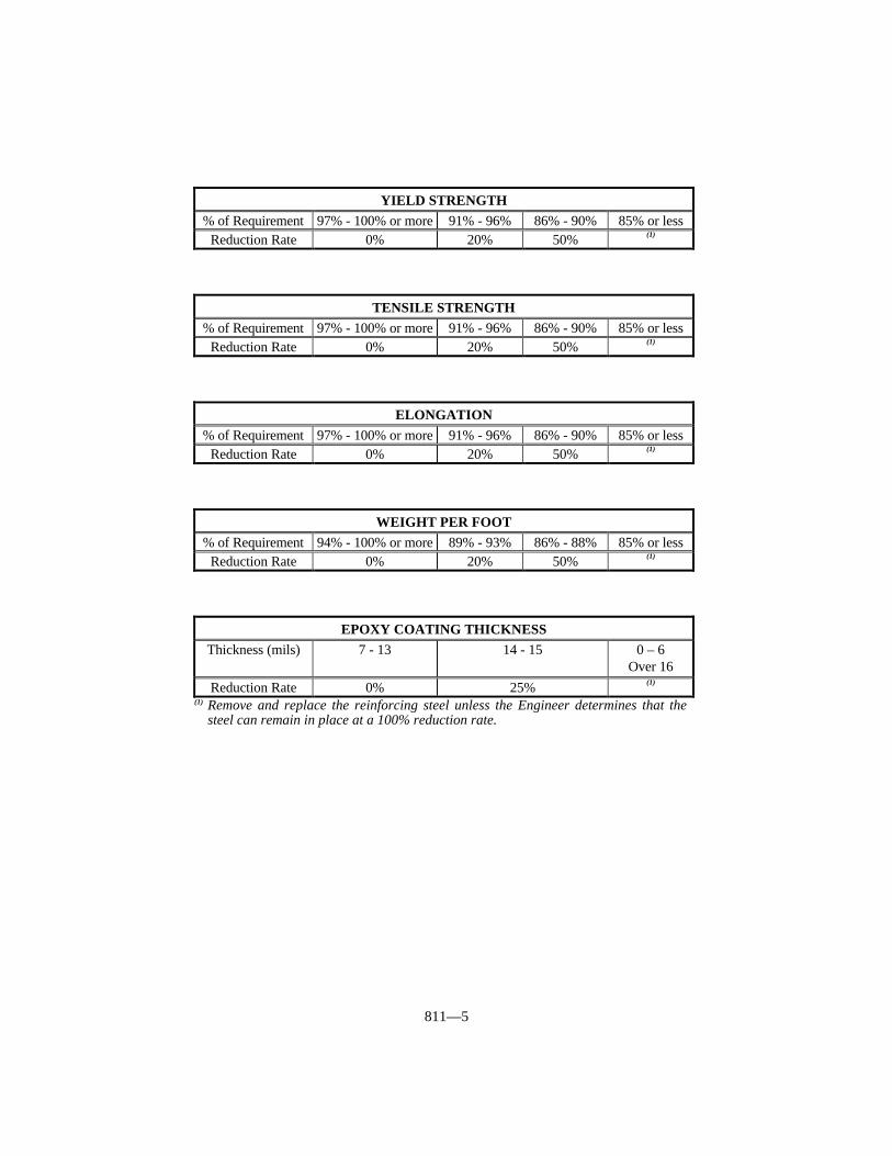
811—5
YIELD STRENGTH% of Requirement 97% - 100% or more 91% - 96% 86% - 90% 85% or less
Reduction Rate 0% 20% 50% (1)
TENSILE STRENGTH% of Requirement 97% - 100% or more 91% - 96% 86% - 90% 85% or less
Reduction Rate 0% 20% 50% (1)
ELONGATION% of Requirement 97% - 100% or more 91% - 96% 86% - 90% 85% or less
Reduction Rate 0% 20% 50% (1)
WEIGHT PER FOOT% of Requirement 94% - 100% or more 89% - 93% 86% - 88% 85% or less
Reduction Rate 0% 20% 50% (1)
EPOXY COATING THICKNESSThickness (mils) 7 - 13 14 - 15 0 – 6
Over 16Reduction Rate 0% 25% (1)
(1) Remove and replace the reinforcing steel unless the Engineer determines that thesteel can remain in place at a 100% reduction rate.

812—1
SECTION 812 STRUCTURAL STEELS
812.01 STRUCTURAL STEEL SHAPES, PLATES, BARS, AND FASTENERS.Conform to Charpy V-notch toughness requirements for structural steel for load carryingmembers in bridges when specified in the Plans.
812.01.01 Structural Steel, All Types. Conform to AASHTO M 270 (ASTM A709), Grades 36, 50 50W, 70W, HPS70W, 100 and 100W. When the supplementaryrequirement of this specification are specified, they exceed the requirements of ASTM A36, A 514, A 572, A 588, and ASTM A 852.
A) Structural Steel. Conform to AASHTO M 270 Grade 36, ASTM A 709 Grade36, or ASTM A 36.
B) High-Strength Low-Alloy Columbium-Vanadium Steels of StructuralQuality. Conform to AASHTO M 270 Grade 50, or ASTM A 709 Grade 50, orASTM A 572.
C) High-Strength Low-Alloy Structural Steel with 345 MPa Minimum YieldPoint to 4 Inches Thick. Conform to AASHTO M 270 Grade 50W, ASTM M270 Grade 50W, or ASTM A 588.
D) Quenched and Tempered Low-Alloy Structural Steel Plate with 485 MPaMinimum Yield Strength to 4 Inches Thick. Conform to AASHTO M 270Grade 70W, ASTM A 709 Grade 70W, or ASTM A 852.
E) High-Yield-Strength, Quenched and Tempered Alloy Steel Plate, Suitablefor Welding. Conform to AASHTO M 270 Grade 100/100W, ASTM A 709Grade 100/100W, or ASTM A 514.
F) High-Strength Low-Alloy, Quenched and Tempered Structural Steel Plate. Conform to ASTM A 709 Grade HPS70W.
812.01.02 Hot-Rolled Carbon Steel Sheets and Strip of Structural Quality,Grade 33 (Corrugated Steel Plank for Bridge Floors). Conform to ASTM A 570.
812.01.03 Cold Rolled Carbon Steel Sheet of Structural Quality, Grade “D” (40ksi) (Corrugated Steel Plank for Bridge Floors). Conform to ASTM A 611.
812.01.04 Steel Sheet Piling. Conform to AASHTO M 202 (ASTM A 328).
812.01.05 Frames and Grates (for Catch Basins, Inlets, Outlets, and Manholes). Use steel in these items that conforms to the following properties:
Yield Strength 36 ksi. minimumTensile Strength 58 ksi mimimumElongation in 2-inch specimen 21 percent minimum
The Department will accept steel for frames and grates according to the Manual ofField Sampling and Testing Practices.
813—1
SECTION 813 MISCELLANEOUS METALS
813.01 PINS AND ROLLERS. Use steel specified in the AASHTO StandardSpecifications for Highway Bridges conforming to AASHTO M 169 (ASTM A 108) orAASHTO M 102 (ASTM A 668).
813.02 STEEL CASTING. Conform to AASHTO M 103, Grade 70-36 (ASTM A 27).
813.03 EXPANDING STEEL MANHOLE RISERS. Use an approved type thatexpands to fit tightly and rigidly within the existing frame.
813.04 GRAY IRON CASTINGS. Conform to AASHTO M 105, Class 30-B.
813.05 MALLEABLE CASTINGS. Conform to ASTM A 47. Use the gradespecified.
813.06 CASTINGS FOR RIGHT-OF-WAY MARKERS. Provide aluminum alloyconforming to ASTM B 26, Alloy 319.1.
813.07 LEAD PLATES. Manufacture plates from lead conforming to ASTM B 29.
813.08 ALUMINUM.
813.08.01 Cast Aluminum Sand Castings. Conform to ASTM B 26, Alloy356.0-T6.
813.08.02 Aluminum Alloy Permanent Mold Castings. Conform to ASTM B 108.
813.08.03 Aluminum Alloy Sheet and Plate. Conform to ASTM B 209.
813.08.04 Aluminum Alloy Extruded Bars, Rods, Shapes and Tubes. Conformto ASTM B 221, Alloy 6061-T 6511 or Alloy 6063-T 6.
813.08.05 Aluminum Alloy Rolled or Extruded Shapes. Conform to ASTM B308, Alloy 6061-T6.
813.08.06 Aluminum Alloy Seamless Pipe. Conform to ASTM B 241, Alloy6061-T 6 and 6063-T 6.
813.08.07 Aluminum and Aluminum Alloy Bars, Rods, and Wire Bolts. Conform to ASTM F 468, Alloy 2024-T 4. Give finished bolts a minimum anodic coatingof 0.0002 inch.
813.08.08 Aluminum Nuts. Conform to ASTM F 467, Alloy 6061-T6 or 6062-T 9. Give finished nuts a minimum anodic coating of 0.0002 inch.
813.08.09 Welding Rods. Conform to AWS A5.10.
813.09 STEEL BOLTS, NUTS, AND WASHERS.
813.09.01 Carbon Steel Bolts and Nuts. Conform to ASTM A 307. Nuts conformto AASHTO M 291.
813.09.02 High-Strength Steel Bolts, Nuts, and Washers. Mark all bolts, nuts,and washers according to the appropriate ASTM Specifications. If using galvanized bolts,nuts, or washers, measure the thickness of the zinc coating. Take measurements on thewrench flats or top of bolt head.
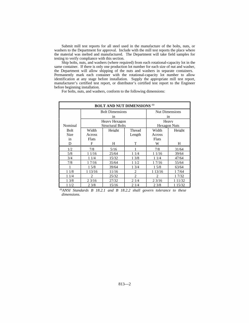
813—2
Submit mill test reports for all steel used in the manufacture of the bolts, nuts, orwashers to the Department for approval. Include with the mill test reports the place wherethe material was melted and manufactured. The Department will take field samples fortesting to verify compliance with this section.
Ship bolts, nuts, and washers (where required) from each rotational-capacity lot in thesame container. If there is only one production lot number for each size of nut and washer,the Department will allow shipping of the nuts and washers in separate containers. Permanently mark each container with the rotational-capacity lot number to allowidentification at any stage before installation. Supply the appropriate mill test report,manufacturer’s certified test report, or distributor’s certified test report to the Engineerbefore beginning installation.
For bolts, nuts, and washers, conform to the following dimensions:
(1)ANSI Standards B 18.2.1 and B 18.2.2 shall govern tolerance to thesedimensions.
BOLT AND NUT DIMENSIONS (1)
Bolt Dimensions Nut Dimensionsin in
Heavy Hexagon HeavyNominal Structural Bolts Hexagon Nuts
Bolt Width Height Thread Width HeightSize Across Length Acrossin Flats FlatsD F H T W H
1/2 7/8 5/16 1 7/8 31/645/8 1 1/16 25/64 1 1/4 1 1/16 39/643/4 1 1/4 15/32 1 3/8 1 1/4 47/647/8 1 7/16 35/64 1 1/2 1 7/16 55/641 1 5/8 39/64 1 3/4 1 5/8 63/64
1 1/8 1 13/16 11/16 2 1 13/16 1 7/641 1/4 2 25/32 2 2 1 7/321 3/8 2 3/16 27/32 2 1/4 2 3/16 1 11/321 1/2 2 3/8 15/16 2 1/4 2 3/8 1 15/32
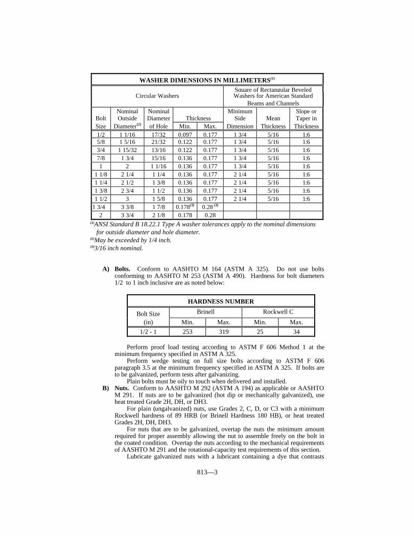
813—3
(1)ANSI Standard B 18.22.1 Type A washer tolerances apply to the nominal dimensionsfor outside diameter and hole diameter.
(2)May be exceeded by 1/4 inch.(3)3/16 inch nominal.
A) Bolts. Conform to AASHTO M 164 (ASTM A 325). Do not use boltsconforming to AASHTO M 253 (ASTM A 490). Hardness for bolt diameters1/2 to 1 inch inclusive are as noted below:
Perform proof load testing according to ASTM F 606 Method 1 at theminimum frequency specified in ASTM A 325.
Perform wedge testing on full size bolts according to ASTM F 606paragraph 3.5 at the minimum frequency specified in ASTM A 325. If bolts areto be galvanized, perform tests after galvanizing.
Plain bolts must be oily to touch when delivered and installed.B) Nuts. Conform to AASHTO M 292 (ASTM A 194) as applicable or AASHTO
M 291. If nuts are to be galvanized (hot dip or mechanically galvanized), useheat treated Grade 2H, DH, or DH3.
For plain (ungalvanized) nuts, use Grades 2, C, D, or C3 with a minimumRockwell hardness of 89 HRB (or Brinell Hardness 180 HB), or heat treatedGrades 2H, DH, DH3.
For nuts that are to be galvanized, overtap the nuts the minimum amountrequired for proper assembly allowing the nut to assemble freely on the bolt inthe coated condition. Overtap the nuts according to the mechanical requirementsof AASHTO M 291 and the rotational-capacity test requirements of this section.
Lubricate galvanized nuts with a lubricant containing a dye that contrasts
WASHER DIMENSIONS IN MILLIMETERS(1)
Square of Rectangular BeveledCircular Washers Washers for American Standard
Beams and ChannelsNominal Nominal Minimum Slope or
Bolt Outside Diameter Thickness Side Mean Taper inSize Diameter(2) of Hole Min. Max. Dimension Thickness Thickness1/2 1 1/16 17/32 0.097 0.177 1 3/4 5/16 1:65/8 1 5/16 21/32 0.122 0.177 1 3/4 5/16 1:63/4 1 15/32 13/16 0.122 0.177 1 3/4 5/16 1:67/8 1 3/4 15/16 0.136 0.177 1 3/4 5/16 1:61 2 1 1/16 0.136 0.177 1 3/4 5/16 1:6
1 1/8 2 1/4 1 1/4 0.136 0.177 2 1/4 5/16 1:61 1/4 2 1/2 1 3/8 0.136 0.177 2 1/4 5/16 1:61 3/8 2 3/4 1 1/2 0.136 0.177 2 1/4 5/16 1:61 1/2 3 1 5/8 0.136 0.177 2 1/4 5/16 1:6
1 3/4 3 3/8 1 7/8 0.178(3) 0.28 (3) 2 3 3/4 2 1/8 0.178 0.28
HARDNESS NUMBER
Bolt Size Brinell Rockwell C
(in) Min. Max. Min. Max.1/2 - 1 253 319 25 34

813—4
with the color of the galvanizing.Perform proof load testing according to ASTM F 606, paragraph 4.2 at the
minimum frequency specified in AASHTO M 291 or AASHTO M 292 (ASTMA 194). If nuts are to be galvanized, perform tests after galvanizing, overtapping,and lubricating.
C) Washers. Conform to AASHTO M 293. If supplying galvanized washers,perform hardness testing after galvanizing. Remove coating before takinghardness measurements.
D) Rotational-Capacity Test. Perform rotational-capacity tests on all black orgalvanized (after galvanizing) bolt, nut, and washer assemblies by themanufacturer or distributor before shipping. Perform additional rotational-capacity tests on each lot at job sit. Use washers as part of the test even thoughthey may not be required as part of the installation procedure. Perform thefollowing:
1) Except as modified herein, perform rotational-capacity testing according toAASHTO M 164.
2) Test each combination of bolt production lot, nut lot, and washer lot,shipped as a rotational-capacity lot, as an assembly. Where washers are notrequired by the installation procedures, the Department will not require lotidentification for them.
3) Assign a rotational-capacity lot number to each combination of lots tested.4) Test at least 2 assemblies per rotational-capacity lot.5) Assemble the bolt, nut and washer assembly in a Skidmore-Wilhelm
Calibrator or an acceptable equivalent device (Note this requirementsupersedes the ASTM A 325 requirement that the test be performed in asteel joint). For bolts too short to be assembled in the Skidmore-WilhelmCalibrator, test them according to 9) below.
6) Provide the minimum rotation, from a snug tight condition (10 percent of thespecified proof load), as follows:
300 degrees (0.83 turn) for bolt lengths ≤ 4 diameters360 degrees (1 turn) for bolt lengths > 4 diameters and ≤ 8 diameters480 degrees (1.33 turns) for bolt lengths > 8 diameters
7) Ensure that the tension reached at the above rotation is ≥ 1.15 times therequired installation tension. The installation tension and the tension for theturn test are as noted below:
8) After exceeding the required installation tension listed above, take and
TENSION
Diameter Req. Installation Turn Test Tension(inches) Tension (kips) (kips)
1/2 12 145/8 19 223/4 28 327/8 39 451 51 59
1 1/8 56 641 1/4 71 821 3/8 85 981 1/2 103 118

813—5
record one reading of tension and torque. Ensure that the torque valueconforms to the following:Torque ≤ 0.25 PD
Where: Torque = measured torque (foot-pounds)P = measured bolt tension (pounds)D = bolt diameter (feet)
9) Test bolts too short for assembly in a Skidmore-Wilhelm Calibrator in asteel joint. Disregard the tension requirement of 7) above. For themaximum torque requirement of 8) above, use a value of P equal to the turntest tension shown in the table in 7) above.
The Department will not require an inspection agency present duringtesting; however, the manufacturer or distributor performing the tests shallcertify that the results recorded are accurate. The Engineer reserves the rightto witness testing on request.
Ensure that the lot number appearing on the shipping package for bolts,washers, and nuts corresponds to the lot number identified on thedistributor’s and manufacturer’s certification.
Provide the Engineer with the certified test report from the manufactureror distributor performing the rotational-capacity test. Include the followinginformation:
a) The lot number of each of the items tested.b) The rotational-capacity lot number.c) A statement that the items conform to this section and the Contract.d) The results of the tests.e) The location and date of the tests.f) The location where the bolt assembly components were manufactured.
813.09.03 Corrosion-Resisting Steel Bolts and Set Screws. Fabricate bolts andscrews from bars conforming to ASTM A 276. Use Types 302 or 304 for steel machinebolts to attach aluminum posts to concrete and for steel set screws for aluminum railings.
813.09.04 Stainless Steel Hardware, Bolts, Nuts, and Washers. Conform toASTM A 320.
813.09.05 Cadmium Coatings for Steel Anchor Bolts, Nuts, and Washers. Conform to ASTM B 766, Class 12, Type II.
813.10 WELDING MATERIAL, PROCEDURES, AND INSPECTION. Forbridges comply with the ANSI/AASHTO/AWS D1.5 Bridge Welding Code withmodifications and additions as specified in the Plans.
For other steel structures comply with the AWS Structural Welding Code D1.1 withmodifications and additions as specified in the Plans. For aluminum structures complywith the AWS Structural Welding Code-Aluminum D1.2.
813.11 STUD SHEAR CONNECTORS. Conform to AASHTO M 169 (ASTM A 108,Grade 1015).
813.12 HANDRAIL.
813.12.01 Type B. Fabricate the channel, picket, and posts using hot rolled steelconforming to AISI M 1020; ASTM A 519, Grade 1020; ASTM A 575, Grade M 1020; orASTM A 659, Grade 1020. For the lambs tongue, use either a gray iron casting or acommercial grade steel. After fabrication and cleaning, paint the handrail with 2 coats ofcommercial grade primer paint and one coat of commercial grade black enamel. Repaint
813—6
damaged areas as directed.
813.12.02 Type C. Furnish aluminum posts and rails conforming to ASTM B 221,alloy 6063, temper T52. Provide rails with a polished finish and posts and fittings with asatin finish. Use aluminum alloy fittings for handrails as recommended by the handrailmanufacturer.
813.13 MATTRESSES AND GABIONS. Conform to ASTM A 975, Style 1 orASTM A 974, Style 1 or 2. Use wire with a minimum elongation of 10 percent of thelength of the wire when tested according to ASTM A 370 without reducing the diameter ortensile strength of the wire.
Supply lacing wire in sufficient quantity to ensure that all required tying, connecting,and lacing can be performed. For Department direct purchases, supply an amount oflacing wire equal to or greater than 8 percent of the weight of the units.
Fabricate the mattress units to the dimensions required by the Contract. TheDepartment will accept mattresses with dimensions within ± 3 percent of the orderedwidth.
813.13.01 Mattress Units. As an alternate to lacing wire, the Engineer will allowmattress unit fasteners, from the Department’s List of Approved Materials, that conform tomattress unit manufacturer’s recommended assembly and connection instructions.
Subdivide the mattress units into compartments a maximum of 3 feet in lengthextending over the full width of the mattress unit by inserting diaphragms made of thesame mesh as the rest of the mattress unit. Secure the diaphragms in position on thebottom with a continuous spiral wire at the factory so no additional tying at this joint isnecessary.
813.13.02 Gabion Baskets. As an alternate to lacing wire, the Engineer will allowgabion unit fasteners, from the Department’s List of Approved Materials, that conform tomattress unit manufacturer’s recommended assembly and connection instructions.
Supply diaphragms of the same material composition as the gabion to form individualcells of equal length and width when the gabion length exceeds its width.
813.13.03 Acceptance. The Department will test each shipment for wire size andzinc coating, and will perform any other Engineer ordered tests. The Department willaccept shipments based on laboratory testing and the Engineer’s visual inspection.
814—1
SECTION 814 GUARDRAIL SYSTEMS
814.01 DESCRIPTION. This section covers material requirements for corrugatedsheet steel beams and accessories for guardrail, terminal sections, guardrail posts, offsetblocks, end treatments, and timber guard posts.
814.02 BEAMS AND ACCESSORIES. Conform to AASHTO M 180. Hardware forType I, II, or III beams may be either hot-dip galvanized, electrogalvanized, ormechanically galvanized. Galvanize according to AASHTO M 232. The Engineer willreject beams with zinc oxide (white rust) in amounts deemed objectionable. Furnish TypeII beams of either Class A, 0.105 inch thick or Class B, 0.135 inch thick as specified in theContract.
814.03 TERMINAL SECTIONS. Conform to AASHTO M 180 and the details shownon the Standard Drawings. Galvanize sections after fabrication. Furnish Type 2 sectionsof either Class A, 0.105 inch thick or Class B, 0.135 inch thick as specified in theContract.
814.04 GUARDRAIL POSTS. Provide either steel or timber, and use the same typethroughout the Project.
814.04.01 Steel Guardrail Posts. Fabricate from steel conforming to ASTM A 36for the wide flange shapes. Punch or drill holes for connector bolts before galvanizing. Galvanize all posts according to AASHTO M 111.
814.04.02 Timber Guardrail Posts. Furnish either square sawn or round timberguardrail posts. Conform to the nominal dimensions shown on the Standard Drawings. The Engineer will allow a minus 2-inch tolerance from the specified nominal length. Sawthe butts of all posts square, and finish the tips as specified in the Contract.
Bore bolt holes to a driving fit for the bolts. Frame, bore, and trim, as much as ispractical, before giving the posts a preservative treatment. When it is necessary to bore orcut the posts after treatment, or when any treated surface has been badly scarred, treat thecut or scarred surface according to AWPA M4.
Treat the posts with preservative according to AWPA C 14 as applicable for guardrailposts. Use only one type throughout the project unless otherwise approved by theEngineer.
Use any of the species of wood for round guardrail posts covered under AWPA C 5. Use any of the softwood species for square sawed posts covered under AWPA C 2. Whenfurnishing oak posts, treat with creosote or creosote solution according to AWPA C 2 for“Above Ground, Soil or Fresh Water Exposure.”
See Subsection 818.01 for inspection, testing and acceptance procedures for TimberGuardrail Posts.
A) Square Sawed Posts. Ensure the posts, in the direction parallel to the axis of thebolt holes, do not exceed the dimensions specified in the Contract by more than1/4 inch.
Use posts that have straight grain, and that have a slope of the grain notdeviating more than one inch in 12 inches from being parallel to any face whenmeasured over the middle one-half of the length. The Engineer will not acceptposts having a crook exceeding 1/2 inch in 10 feet. Limit wane to one end of thepost only, and do not allow it to extend more than 10 feet from that end. Do notreduce the flat width of any face by more than 25 percent at the point of mostwane. Do not use wood with ant tunnels, woodpecker holes, plugged holes, orany large unsightly gaps. The Department will allow wood with grub and wormholes less than 1/2 inch in average diameter, provided that the sum of thediameters of all holes in any 12 inches of post length does not exceed 1/4 the

814—2
nominal width of the face. Do not use posts showing signs of powder post beetleinfestation. The Engineer will not limit the use of posts that have grub holesappearing entirely on the surface of the post and that do not penetrate to morethan 1/2 inch in maximum depth.
Do not use posts with knots greater than 3/8 the nominal width of the face,measured by the smallest diameter. Do not allow the sum of the diameters of allknots in any 6 inches of post length to exceed 3/4 the nominal width of the face. Do not allow the sum of the diameter of all knots appearing within the middlehalf of the length of any face to be greater than 4 times the size of the largest knotallowed in that face. The Department will allow posts with unsound knots nolarger than half the maximum allowable size for sound knots and no more than 11/2 inches in depth, provided that the surrounding wood is not affected by thedecay. Do not use posts that have clusters of knots where the maximumdistortion of the grain around the cluster exceeds the maximum allowable size forone knot.
Entirely confine shakes within the ends of the post, without extending to anyface. Measure the shake as the sum of the 2 adjoining sides of the smallestrectangle that will completely enclose the shake. Measure the sides of therectangle parallel to the faces of the post. Do not allow shakes to occur in morethan one annual ring or to extend to more than 3/4 of the circumference of theannual ring in boxed heart. Do not allow total shake measurement to exceed one-half the width of the face.
Do not use posts with splits greater in length than the width of the face. Donot use posts with a check or series of contiguous checks having a width of 8 mmor greater at the surface and more than 3 inches in depth at any point andextending more than 3/4 of the length of the post from one end. The Engineerwill determine the depth of checks by the penetration of a probe 1/64 inch thickand 1/4 inch wide. The Engineer will consider the extent of a check or series ofcontiguous checks to end at the last point where the opening does not exceed 1/8inch in width and is no more than 3/4 inch in depth.
Do not use any post having a shake that does not exceed the maximumlimits for shakes as specified herein, but contains a check which penetrates to theannual ring in which the shake occurs.
B) Round Posts. Peel all posts for their full length, and remove all outer and innerbark. Shave all knots and projections smooth and flush with the surface of thesurrounding wood.
Ensure that the posts are a constant diameter not less than 1/4 inch under thenominal diameter.
Do not use posts that have short or reverse bends, one way sweepsexceeding one inch, and winding twists that are unsightly and exaggerated. TheEngineer will not allow more than 10 percent of the number of pieces of anyshipment to contain the maximum sweep.
Do not use posts with unsound, loose or hollow knots. The Department willallow use posts that have sound knots when the diameter of any one knot orwhen the combined diameters of 2 or more knots occurring in the same crosssection are no greater than 1/3 of the diameter of the post at that cross section.
Ensure that posts are close grained and do not show spiral grain exceeding1/8 turn in 5 feet.
Do not use posts with seasoning checks that penetrate the interior of the postto a depth greater than 1/3 of the diameter at any point, or which measure morethan 1/4 inch in width at any point.
Do not use posts that have ring shakes, sap rot, bird pecks, insect holes,pitch pockets, or pitch streaks, and other defects that will impair the strength ofthe post, or give it an unsightly appearance.
814.05 OFFSET BLOCKS. Use the size, and when specified, the type the Contractspecifies.

814—3
814.05.01 Wood. Conform to 814.04 for material properties.
814.05.02 Composite Plastic. Use blocks that are uniform in compositionthroughout the product and consist of at least 70 percent plastic by weight. Rubber is anacceptable alternative to plastic in their composition. Use sufficient additives to inhibitphoto degradation. The Department will consider 2 percent carbon black to be aminimum. Ensure the blocks conform to the National Cooperative Highway ResearchProgram (NCHRP) 350 Test Level 3 requirements.
Submit a written manufacturer’s certification to the Engineer stating the materialcomposition conforms to this subsection and is the same that was tested and approvedunder NCHRP 350.
814.06 MATERIALS FOR END TREATMENTS. Conform to Subsections 814.02through 814.05 for common components, and, except where otherwise provided, ensurethey are of the same class and type as required for the guardrail to which they are attached. Galvanize all non-corrosion-resistant metals used in end treatments according toAASHTO M 111 or AASHTO M 232 as applicable. For other materials, comply with thefollowing requirements:
A) Anchorage Systems. Furnish anchorage systems that have a minimum breakingstrength of 40,000 pounds. The anchorage system may employ either a cableassembly or continuous steel rod or other system of equal or greater strength whenapproved. For cable assemblies, use cable that is 3/4-inch (6 by 19) wire ropeconforming to AASHTO M 30, Class C. Provide swage fittings as required by theStandard Drawings and include studs as required. Ensure that eye bolts conform toASTM A 489 and are of either Type 1 or Type 2. For wire rope clips use acommercial grade capable of being torqued to a minimum of 130 foot-pounds.
Use commercial grade wire rope thimbles.B) Anchor and Miscellaneous Plates. Fabricate from steel conforming to Subsection
812.01.01.C) Miscellaneous Hardware.
Bolts ASTM A 307Nuts ASTM A 563, Grade A or better
D) Steel Sheet (for rail plates and mounting brackets). Conform to ASTM A 1011,Type SS, Grade 36
E) Tubular Sections (for posts and blocks). Conform to ASTM A 500, Grade B orASTM A 501.
F) Steel Drums. For steel drums conform to Federal Specification PPP-D-729C forType II, straight side, with rolled or expanded hoops, cylindrical drum; double seamedwithout chime reinforcement. Ensure that average diametrical crushing strength perdrum is 6,000 pounds with maximum variation for 10 tests being 400 pounds.Galvanize steel drums on all surfaces according to AASHTO M 111.
G) Concrete. Conform to Section 601, Class A.H) Welded Wire Fabric. Use welded wire fabric for concrete reinforcement that is W3
by W3, 6 by 6-inch conforming to Subsection 811.04. The Department may allowother approved types of steel reinforcement.

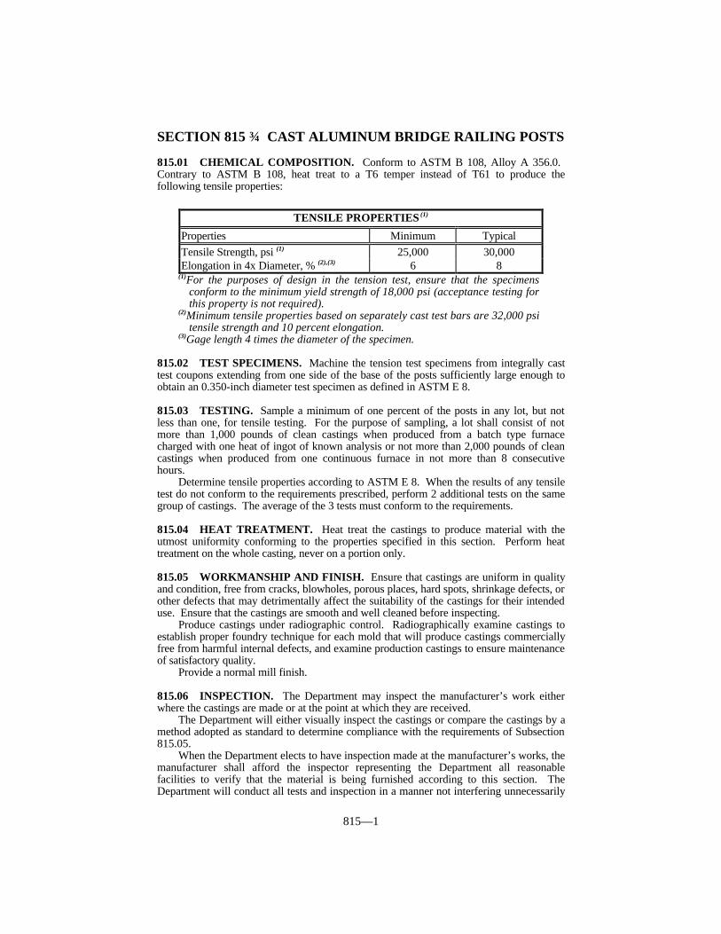
815—1
SECTION 815 CAST ALUMINUM BRIDGE RAILING POSTS
815.01 CHEMICAL COMPOSITION. Conform to ASTM B 108, Alloy A 356.0. Contrary to ASTM B 108, heat treat to a T6 temper instead of T61 to produce thefollowing tensile properties:
(1)For the purposes of design in the tension test, ensure that the specimensconform to the minimum yield strength of 18,000 psi (acceptance testing forthis property is not required).
(2)Minimum tensile properties based on separately cast test bars are 32,000 psitensile strength and 10 percent elongation.
(3)Gage length 4 times the diameter of the specimen.
815.02 TEST SPECIMENS. Machine the tension test specimens from integrally casttest coupons extending from one side of the base of the posts sufficiently large enough toobtain an 0.350-inch diameter test specimen as defined in ASTM E 8.
815.03 TESTING. Sample a minimum of one percent of the posts in any lot, but notless than one, for tensile testing. For the purpose of sampling, a lot shall consist of notmore than 1,000 pounds of clean castings when produced from a batch type furnacecharged with one heat of ingot of known analysis or not more than 2,000 pounds of cleancastings when produced from one continuous furnace in not more than 8 consecutivehours.
Determine tensile properties according to ASTM E 8. When the results of any tensiletest do not conform to the requirements prescribed, perform 2 additional tests on the samegroup of castings. The average of the 3 tests must conform to the requirements.
815.04 HEAT TREATMENT. Heat treat the castings to produce material with theutmost uniformity conforming to the properties specified in this section. Perform heattreatment on the whole casting, never on a portion only.
815.05 WORKMANSHIP AND FINISH. Ensure that castings are uniform in qualityand condition, free from cracks, blowholes, porous places, hard spots, shrinkage defects, orother defects that may detrimentally affect the suitability of the castings for their intendeduse. Ensure that the castings are smooth and well cleaned before inspecting.
Produce castings under radiographic control. Radiographically examine castings toestablish proper foundry technique for each mold that will produce castings commerciallyfree from harmful internal defects, and examine production castings to ensure maintenanceof satisfactory quality.
Provide a normal mill finish.
815.06 INSPECTION. The Department may inspect the manufacturer’s work eitherwhere the castings are made or at the point at which they are received.
The Department will either visually inspect the castings or compare the castings by amethod adopted as standard to determine compliance with the requirements of Subsection815.05.
When the Department elects to have inspection made at the manufacturer’s works, themanufacturer shall afford the inspector representing the Department all reasonablefacilities to verify that the material is being furnished according to this section. TheDepartment will conduct all tests and inspection in a manner not interfering unnecessarily
TENSILE PROPERTIES (1)
Properties Minimum TypicalTensile Strength, psi (1) 25,000 30,000Elongation in 4x Diameter, % (2),(3) 6 8

815—2
with the operation of the works.
815.07 INSPECTION REPORTS. When requested by the Department, furnishcertified inspection reports certifying compliance with the requirements of this section.

816—1
SECTION 816 WOVEN-WIRE FENCING MATERIALS
816.01 DESCRIPTION. This section covers the materials for use in construction ofwoven-wire fences.
816.02 GENERAL. Galvanize all ferrous materials used in a complete installation offence, except aluminum coated fabric, aluminum coated posts and braces, or aluminumcoated barbed wire. Galvanize all iron and steel hardware according to AASHTO M 232.Galvanize other components as designated. Where it is not practical to secure a specimenof measurable area or uniform thickness for determining the weight of zinc coating, ensurethat all such galvanizing withstands 4 dips of the Preece Test as set out in ASTM A 239. Ensure that post caps and socket type brace connections are galvanized malleable iron, orother approved type, and designed to exclude moisture from inside posts or rails.
816.03 WOVEN WIRE FABRIC. Ensure that the woven wire fabric is either zinc-coated steel or aluminum-coated steel. Provide the size and style of fabric specified in theContract.
Use zinc-coated steel fabric that conforms to ASTM A 116 and that has a Class 3coating.
Use aluminum-coated steel fabric that conforms to ASTM A 584.
816.04 BARBED WIRE. Use either zinc-coated steel, aluminum-coated steel, oraluminum alloy. Use barbs of 4-point pattern spaced at intervals of 5 inches. The wire forbarbs may be either round or half-round.
816.04.01 Zinc-Coated Steel. Conform to ASTM A 121. Use size 0.099-inchdiameter or heavier with Class 3 coating. The Department will allow high tensile strengthbarbed wire provided it conforms to ASTM A 121, and the following exceptions: (1)nominal diameter of 0.067 inch for the coated line wires and 0.057 inch for the coatedbarbs; (2) minimum weight of zinc coating of 0.75 ounces per square foot for line wiresand 0.70 ounces per square foot for barbs; and (3) minimum tensile strength of 475 poundsfor each individual strand of the line wire.
816.04.02 Aluminum-Coated Steel. Use either Type I or Type II conforming toASTM A 121. Use size 0.099 inch diameter or heavier.
816.04.03 Aluminum Alloy. Use 2 strands of 0.110 inch nominal diameter orheavier wire strands having minimum tensile strength of 42,000 psi, minimum yieldstrength of 35,000 psi and minimum elongation of 10 percent.
816.05 BRACE WIRE. Conform to ASTM A 777-91 except provide a minimumweight of coating of 0.6 ounce per square foot. Use size 0.148-inch nominal diameter orlarger.
816.06 FABRIC TIES. Use either a minimum 0.109-inch nominal diametergalvanized steel conforming to ASTM F 626, except ensure that the minimum weight ofcoating is 0.6 ounces per square foot, or 0.148-inch nominal diameter aluminum alloy.
816.07 FENCE POSTS AND BRACES.
816.07.01 Steel Posts and Braces. Conform to ASTM F 1043, ASTM F 1083, andthe Standard Drawings.
When the Contract specifies a thermoplastic acrylic coating, apply a chromateconversion coating at the manufacturer’s recommended rate. Ensure that the coating isdesigned for pretreatment of galvanized coatings. After pretreating, electrostatically applythe thermoplastic acrylic coating with a minimum dry film thickness of 0.3 mils.
816—2
816.07.02 Wood Posts and Braces. Treat wood fence posts and braces withpreservative and ensure that they are made of timber cut from live, sound, standing trees. See Subsection 818.01 for inspection, testing and acceptance of wood products. Ensurethat round or half-round posts and braces are preservative treated according to and are ofthe species covered by AWPA C 5. Ensure that sawed posts and braces are preservativetreated according to and are of the species covered by AWPA C 2 for “Soil or Fresh WaterExposure”.
Use posts that are round, half-round, or square-sawed.Ensure that wood for fence posts is sound and free from decay, excessive knots,
seasoning checks, and end splits that will affect serviceability. The Department will allowsound knots, provided the width of the knot does not exceed one-third the diameter of around post at the point where it occurs, or one-third the width of any face of a sawed post,or a maximum of 2 1/2 inches. The Department will reject wood with season checks thatpenetrate more than one-third of the diameter of the piece or which have a width of morethan 1/4 inch.
Use round posts and half-round posts that are free of multiple crooks. TheDepartment will allow crooks in one plane only, provided that a straight line between thecenters of the butt and tip does not deviate more than 2 inches from the center of the post atany point. Ensure that crooks in square-sawed posts do not exceed one inch in 5 feet.
Cleanly peel round posts and remove all bark. Strips of inner bark that are less than1/2 inch wide and 3 inches long may remain on the peeled post. Trim all protruding knotsflush with the sides and remove all spurs and splinters. In machine peeling operations,follow the natural taper of round posts. Manufacture half-round posts by sawing in halfthe round posts complying with the above manufacturing methods.
Square cut the ends of all posts unless the Engineer allows driving. When driving isspecified or allowed, point the butt end before receiving preservative treatment. Do notallow the length of the point to exceed 1.5 times the diameter or width of face, asapplicable.
A) Line Posts. Use line posts with a length of 7 feet and a minus one-inchtolerance. Use line posts that are either round, half-round, or square-sawed;however, furnish the same type section for all line posts throughout the project.
Ensure that round posts have a minimum diameter of 4 inches. Ensure thathalf-round posts have a minimum face of 6 inches and a minimum radius of 23/4 inches. Cut square-sawed posts to 4-inch by 4-inch, ± 1/8 inch.
B) End, Corner, Gate, Brace, and Pull Posts. Do not use lengths less than 8 feet.Use either round or square-sawed posts; however, furnish the same type sectionfor all of these types throughout the project. Ensure that round posts have aminimum diameter of 8 inches. Cut square-sawed posts to 8-inch by 8-inch,± 1/8 inch.
C) Braces. Conform to all requirements for line posts, except use braces that areeither round or square-sawed and furnish them in the lengths specified in thePlans.
816.07.03 Untreated Wood Posts. Furnish untreated wood posts of Osage-Orange,Black Locust, Red Cedar, White Oak, or of other approved species, and ensure that postsconform to all applicable requirements of Subsection 816.07.02. Use untreated woodposts only when specified in the Contract.
816.08 GATES. Fabricate gate frames to the size and dimensions specified in theContract. Ensure that pipe used in frames conforms to Subsection 816.07.01. Weld orotherwise construct all joints to form a rigid and water-tight frame.
Furnish all gates complete with approved hinges, latches, and auxiliary braces asrequired.
Fit gate frames with a fabric that conforms to the same requirements as thecorresponding fence.

816—3
The Department may approve the use of gates fabricated of other materials.

817—1
SECTION 817 CHAIN LINK FENCING MATERIALS
817.01 DESCRIPTION. This section covers materials for use in the construction offences of chain link fabric. The Department will allow 3 optional types of fabric; zinc-coated steel, aluminum-coated steel, or aluminum alloy (Type I, II, or III fabric,respectively). Use vinyl coated fabric (Type IV) only when specified in the Contract.
817.02 REQUIREMENTS. Conform to AASHTO M 181 for all materials except steelposts and barbed wire.
817.02.01 Fabric. Use 0.148-inch nominal diameter wire woven in 2-inch mesh. Coat Type I fabric to conform to Class D. Furnish fabric for fences 4 feet and 6 feet highthat has the top selvages knuckled and bottom selvage knuckled or twisted and barbed. Furnish fabric for fences 8 feet high or higher with both top and bottom selvages twistedand barbed.
817.02.02 Barbed Wire. Conform to Subsection 816.04.
817.02.03 Post Caps and Socket Type Brace Connections. Use galvanizedmalleable iron, or other approved type, designed to exclude moisture from inside posts andrails.
817.02.04 Posts, Rails, Gate Frames and Expansion Sleeves. With zinc-coatedsteel fabric or with aluminum-coated steel fabric, use either zinc-coated steel or zinc-acrylic coated steel. With aluminum alloy fabric, use aluminum alloy. Furnish steel poststhat comply with Subsection 816.07.01.
817.02.05 Fabric Ties. Use either a minimum 0.148-inch nominal diameteraluminum alloy or 0.120-inch nominal diameter galvanized steel.
817.02.06 Hog Rings and Tension Wire. With zinc-coated steel fabric or withaluminum-coated steel fabric use zinc-coated steel wire or aluminum-coated steel wire.Ensure that steel ties and wire conform to ASTM F 626, except that the minimum weightof coating is 0.6 ounces per square foot. With aluminum alloy fabric, use aluminum alloywire.
817.02.07 Miscellaneous Fittings and Hardware. With zinc-coated steel fabric orwith aluminum-coated steel fabric use zinc-coated steel. With aluminum alloy fabric, usealuminum alloy.

818—1
SECTION 818 WOOD PRODUCTS
818.01 INSPECTION, TESTING, AND ACCEPTANCE. The Engineer willvisually inspect and approve all treated wood products before use on the project. TheDivision of Materials will grade inspect, sample, and test all treated wood products beforetheir use on the project if the plant producing the wood materials is located within theCommonwealth or a 100-mile driving distance of its borders. When obtaining treatedwood materials from a plant outside this 100-mile distance, have an independent treated-wood testing company approved by the Division of Materials grade inspect, sample, andtest the wood treated material at no expense to the Department. Obtain a report preparedby the independent testing firm that grade inspected, sampled and tested the treated woodmaterial, and submit it to the Division of Materials at least 15 days before using the woodmaterials on the project.
Use only treated wood that has been cut to size before treating. Treat field sawnsurfaces according to AWPA M4.
818.02 BOARDS. Boards are defined as being less than 2-inch in nominal thicknessand one inch or more in width. Only use boards that are one of the available gradesestablished by either the Southern Pine Inspection Bureau (SPIB) or the West CoastLumber Inspection Bureau (WCLIB). The Contract will designate the grade andapplicable inspection bureau.
818.03 DIMENSION LUMBER. Dimension lumber is limited to surfaced softwoodlumber of nominal thickness from 2-inch through 4-inch. Only use dimension lumber forframing members such as joists, planks, rafters, studs, and small timbers.
Use only dimension lumber boards that are one of the available grades established byeither the SPIB or the WCLIB. The Contract will designate the grade and applicableinspection bureau.
818.04 TIMBERS, 5-INCH BY 5-INCH AND LARGER. Use only timbers that areof one of the available grades established by either the SPIB or the WCLIB. The Contractshall designate the dimensions, grade, species, and applicable inspection bureau.
818.05 STRUCTURAL LUMBER. Conform to the AASHTO Standard Specificationsfor Highway Bridges.
818.06 BRIDGE PLANKING AND ROUGH LOCAL HARDWOODS.
818.06.01 Species. Use only bridge planking that is White Oak, Red Oak, orSouthern Yellow Pine.
The term “White Oak” includes White Oak, Chestnut Oak, Post Oak, Burr Oak,Swamp Chestnut Oak, Swamp White Oak, Live Oak, Chinquapin Oak, and other lessknown varieties of oak of this character.
The term “Red Oak” includes Red Oak, Black Oak, Southern Red Oak, Willow Oak,Water Oak, Pin Oak, Cherrybark, or Swamp Red Oak, and other less known varieties ofoak of this character.
Southern Yellow Pine may be any species except Field or Loblolly.
818.06.02 Quality of White Oak or Red Oak. The Engineer will not approve woodfor use that has splits, rot, or unsound knots. Use only pieces that are sawed full tospecified sizes and lengths, with square edges except wane (bark or the lack of wood) asfollows. The Engineer will allow wane on one corner on 30 percent of the pieces in anyshipment, not to exceed 15 percent of the width of the face on which it appears. TheEngineer will allow this grade with sound stains, scattered worm holes or grub holes notmaterially affecting the strength of the piece and sound bird pecks, or their equivalent;sound knots or their equivalent not exceeding in diameter 25 percent the width of the face
818—2
in which they appear. Use only boxed heartcenter wood products. Cut pieces not largeenough to box the heartcenter outside the heart except that sizes 2 to 6 inches in thickness,6 inches wide and wider, may show heart on one face only, in 30 percent of the pieces inany shipment.
818.06.03 Quality of Southern Yellow Pine. Conform to the SPIB grades asfollows:
A) Structural Light Framing (2-inch by 2-inch to 4-inch by 4-inch). Provide No.1 Dense.
B) Structural Joists and Planks (3-inch by 8-inch or 4-inch by 6-inch). ProvideNo. 1 Dense.
C) Stress Rated Timbers (5-inch by 5-inch and larger). Provide No. 1 SR.
818.06.04 Dimensions and Tolerances. Use rough timber that is cut full size asspecified, sawed true with parallel faces. The Engineer will allow no more than 25 percentof a lot or shipment to be scant 1/4 inch in thickness and no more than 10 percent of a lotor shipment may be scant 1/4 inch in width.
Ensure that dressed dimensions for both oak and pine material conform to SouthernPine Inspection Bureau thicknesses and widths for Dimension Lumber.
818.06.05 Rough Local Hardwood. This subsection covers hardwood lumber andtimber that is produced locally. Use only White Oak, Red Oak, or Beech hardwood. Where hardwood material is intended to be used inside, the Department will allow otherspecies of hardwood, that are suitable for the intended use, when such species arespecified.
1) Use only material that is cut from live standing trees and is free from any form ofdecay.
2) The Department does not require seasoned material.3) Cut all pieces to a square edge with no less than 75 percent heart, girth
measurement, for full length of the piece.4) Saw all material to the full nominal dimensions.5) Ensure that all knots are tight and sound. Do not allow any material with a knot
of greater diameter than half of the width of the face on which it occurs. Allowonly one maximum knot, or small knots aggregating in diameter of onemaximum knot, in each one-foot length of timber.
6) Ensure that all material is reasonably free from crook and warp.7) Do not allow any piece that has a shake, crack, or split which extends over half
through the narrow face of the piece.8) Do not allow any boxed heart in pieces less than 3 inches in thickness.9) The Engineer will reject material having any defect or combination of defects that
seriously impairs the strength or that renders it unsatisfactory for the intendeduse.
818.07 PRESERVATIVE TREATMENT. When the Contract specifies preservativetreatment of wood products, treat according to AWPA C14. Provide preservativeconforming to AWPA C14 as the Contract specifies.
Do not use creosote or creosote solutions with wood required to be paintable.When the Contract specifies pentachlorophenol preservative, use heavy petroleum
solvent when the Contract does not require painting. Use light petroleum solvent when theContract requires that the wood is to be paintable.
Do not use water-borne preservatives where the wood will be in contact with waterunless recommended by AWPA specifications.
Follow the guidelines set in AWPA M4 for the care of preservative treated woodproducts.

819—1
SECTION 819 —TUNNEL LINING MATERIALS
819.01 DESCRIPTION. This section covers materials requirements for steel plates andfittings to be used for lining tunnels. Refer to the Contract for sectional properties.
819.01.01 Steel Plates. Use base metal for steel plates that conforms to the chemicalrequirements of ASTM A 569. Ensure that the flat plate, before cold forming, conforms tothe following minimum mechanical properties:
Tensile Strength 42,000 psiYield Strength 28,000 psiElongation, 2 inches 30%
Ensure that nominal plate dimensions provide the sectional properties shown in thecurrent edition of the AASHTO Standard Specifications for Highway Bridges. Forthickness tolerances, conform to Table 6 of AASHTO M 167. Provide steel liner plates ofadditional thickness or protect by coatings or other means when specified in the Contractfor resistance to abrasion or corrosion.
819.01.02 Bolts and Nuts. Do not use any bolts and nuts with lapped seams that areless than 5/8 inch in diameter. Provide bolts conforming to ASTM A 449 for platethicknesses equal to or greater than 0.209 inch and A 307 for plate thickness less than0.209 inch. Provide nuts conforming to ASTM A 307, Grade A.
Only use bolts and nuts with 4-flanged plates of no less than 1/2 inch in diameter forplate thicknesses to and including 0.179 inch and no less than 5/8 inch in diameter forplates of greater thickness.

820—1
SECTION 820 TIMBER POLES
820.01 REQUIREMENTS. Provide poles of Southern Pine conforming to ANSISpecification 05.1. Provide poles of the length and ANSI size classification specified inthe Contract. The Department will not allow sweep exceeding one inch in 10 feet or doublesweep.
Treat poles with pentachlorophenol conforming to AWPA P8 according to AWPAC4. Treat with a light petroleum solvent to provide an oil-free paintable finished product. The Engineer will allow other processes which produce the specified paintability.
Ensure that net retention is no less than 0.075 pounds per cubic foot on the outer 1/2-inch and no less than 0.045 pounds per cubic foot in the 1/2 to one-inch zone with averageretentions of no less than 0.080 and 0.050 pounds per cubic foot, respectively.
Follow the guidelines for the care of preservative treated wood products as set inAWPA M4.
820.02 ACCEPTANCE. The Department will inspect, test and accept poles accordingto Subsection 818.01.
821—1
SECTION 821 — STRUCTURAL STEEL COATINGS
821.01 DESCRIPTION. This section covers requirements for structural steel coatingsystems used in steel bridge construction and maintenance.
821.02 GENERAL REQUIREMENTS. Use only coating system components that arefactory mixed and delivered ready for use. Sediment formed during shipment must beeasily dispersed with a power mixer to produce a smooth, uniform coating having goodspreading characteristics. Reject coatings that excessively gel, or cakes in the container.
Ensure that the coatings produce a smooth uniform finish without sags or streaks. Use Federal Standard No. 141, Methods 4321 and 4331 to test the paints for finishcharacteristics. Ensure that batches of coatings used on an individual structure do notdiffer in color from each other.
Store paint at temperatures above 32 °F and below the maximum temperaturerecommended by the coating manufacturer. The Engineer will reject or retest paintexposed to temperatures outside this range.
821.03 SAMPLING AND TESTING. Apply no coating until the Division ofMaterials has approved it. The Department will sample and test each shipment of eachbatch or lot of coating delivered to the project. Allow the Department 10 working days totest and approve samples. Retest coatings that are not used within 6 months from theirapproval. Additionally, retest coatings that are stored between painting seasons. Removerejected coatings from the job site before starting painting operations.
Use coating systems conforming to this section and on the Department’s List ofApproved Materials. For a manufacturer to place their coating system on the list, see thesubmission process outlined in the Department’s List of Approved Materials.
821.04 ACCEPTANCE PROCEDURE FOR NON-SPECIFICATIONCOATINGS. The Department may accept non-specification coatings at a reduction inpay. Coatings with analytical test results not in conformance to the SpecificationAcceptance Range but within the Acceptance Range with Deduction may be accepted forincorporation into the project with applicable reductions in pay. Deductions arecumulative to a maximum of 60% reduction in pay applied to the Contractors’ invoicedunit cost for the coating. Coatings with 3 or more analytical tests resulting in non-conformance to the Specification Acceptance Range or any analytical test result exceedingthe Acceptance Range with Deduction will be rejected and removed from the project.
821.05 PROJECT ACCEPTANCE. Submit a written manufacturer’s certificationwith each shipment of coating stating that the material furnished conforms to this section. Submit a separate certification for each batch or lot number furnished for each project. Verify that the batch or lot of coating is approved by the Department before applying.

821—2
COATINGS PRICE ADJUSTMENT SCHEDULEAnalytical Test Specification
Acceptance RangeAcceptance Range
with DeductionDeduction
Applied to UnitCost
Density Target Value ± 0.25 lbs/gal
Target Value ± 0.26 to 0.50 lbs/gal
20%
Viscosity Target Value ± 5 KU
Target Value ± 6 to 10 KU
10%
Weight Solids Target Value ± 2.0%
Target Value ± 2.1 to 3.0%
30%
Volume Solids Target Value ± 2.0%
Target Value ± 2.1 to 3.0%
30%
Pigment Target Value ± 2.0%
Target Value ± 2.1 to 3.0%
30%
Metallic PigmentContent
Target Value ± 2.0%
Target Value ± 2.1 to 3.0%
30%
Volatile OrganicCompounds
340 g/L Maximum 341 to 360 g/LMaximum
10%
Color 2.0 ∆E Maximum 2.1 to 3.0 ∆EMaximum
10%
Color Differential 10.0 ∆E Minimum 9.9 to 8.0 ∆EMinimum
10%
Gloss Target Value ± 5 Gloss Units
Target Value ± 5 to 10 Gloss Units
10%
Sag Resistance Target Value ± 10%
Target Value ± 11 to 20%
10%
Drying Schedule Target Value ± 10%
Target Value ± 11 to 20%
10%
Pot Life Target Value ± 10%
Target Value ± 11 to 20%
10%
Resin Content Target Value ± 0.5%
Target Value ± 0.6 to 0.8%
30%

822—1
SECTION 822 ELASTOMERIC BEARING PADS
822.01 ELASTOMERIC BEARING PADS. Furnish elastomeric bearing padsconforming to the design and dimensions as specified in the Plans and to the AASHTOStandard Specifications for Highway Bridges, Division II, Section 18.
Use bearings that are low temperature Grade 3 with durometer hardness of 50 andthat conform to the load test requirements corresponding to Design Method A.

823—1
SECTION 823 CONCRETE CURING MATERIALS
823.01 GENERAL. This section lists the various types of curing materials allowed forconcrete and the materials requirements applicable to each. The Department will providespecifications governing the particular type or types of curing materials allowed forspecific classes of construction in the Contract or other sections of these specifications.
823.02 LIQUID MEMBRANE FORMING COMPOUNDS. Ensure that all curingcompounds Conform to AASHTO M 148 and are from a Department approvedmanufacturer.
1) Type 1-D (Clear with fugitive dye or translucent with fugitive dye), Class A or ClassB.
2) Type 2 (White pigmented), Class A or Class B. Supply Type 2 curing compounds inagitating type drums, except the Department will not require agitating type containerswhen Type 2 curing compound is supplied in 5 gallon pails.
The Department will accept curing compounds on the basis of certification of theirconformance to this section and their being from an approved manufacturer. TheDepartment will reject curing compounds from an unapproved manufacturer and requiretheir removal from the project site.
823.01.02 Acceptance Procedures for Non-Specification Curing Compounds. The Department will test project samples. When non-specification curing compounds areinadvertently incorporated into the work the Department will accept the material with areduction in pay. The Department will apply the largest payment reduction when thematerial fails to meet more than one specification requirement. The Department willcalculate the payment reduction on the invoice cost of the material delivered at the projectsite.
MOISTURE LOSS PAYMENT REDUCTION
kg/square meter 0.00-0.55 0.56-0.65 0.66-0.75 0.76 or moreReduction Rate 0% 20% 30% 50%
REFLECTANCE PAYMENT REDUCTION
% Reflectance 60.0% or more 50-59.9% 40.0-49.9% 39.9% or lessReduction Rate 0% 20% 30% 50%
823.03 BURLAP CLOTH. Conform to AASHTO M 182, Class 4.
823.04 WATERPROOF PAPER (Regular or White). Conform to AASHTO M 171.
823.05 WHITE POLYETHYLENE FILM (White Opaque). Use white polyethylenefilm of either single sheet construction conforming to AASHTO M 171 or laminatedconstruction consisting of 2 sheets of white polyethylene reinforced with synthetic fibercords, providing the total thickness of polyethylene, exclusive of the cords, averages noless than 4 mils and the sheeting conforms to all other applicable requirements ofAASHTO M 171. Incorporate the reinforcing cords diagonally in 2 directions and ensurethat the number of cords averages 24 per linear foot in each direction.
823.06 WHITE BURLAP - POLYETHYLENE SHEET. Conform to AASHTO M171.

823—2
823.07 CURING BLANKETS. Use curing blankets that consist of a top layer of whitecopolymer material and a bottom layer of absorbent, non-woven, synthetic fabric. Ensurethat the layers are securely bonded together so there will be no separation of the layersduring handling and curing of the concrete. When tested according to AASHTO M 171,ensure that moisture loss does not exceed 0.010grams per square centimeter and thatreflectance is at least 70 percent.
824—1
SECTION 824 MASONRY MATERIALS
824.01 CONCRETE MASONRY UNITS (FOR CONSTRUCTION OF CATCHBASINS AND MANHOLES). Conform to ASTM C 139.
824.02 PRECAST REINFORCED CONCRETE MANHOLE SECTIONS.Conform to ASTM C 478, KM 64-115 and the Standard Drawings. For flat top slabs, atongue and groove design is optional. The Department will allow the use of lightweightaggregate provided that it conforms to subsection 805.04.02.
824.03 CONCRETE BRICK. Conform to ASTM C 55. Use Type II, Grade N or S.
824.04 SEWER AND MANHOLE LEVELING BRICK. Conform to AASHTO M91. The Department will waive the requirement for saturation coefficient for Grades SMand MS. Ensure that the dimensions are of the specified standard size.
824.04.01 Sewer Brick. Use Grade SS or SM.
824.04.02 Manhole Brick. Use Grade MS or MM.
824.05 HYDRATED LIME. Conform to ASTM C 206.
825—1
SECTION 825 DE-ICERS
825.01 SOLID (TYPE S) CALCIUM CHLORIDE. Conform to ASTM D 98 for thefollowing:
A) Grade 1. Class A or Class B.B) Grade 2. Class A or Class B.C) Grade 3. Class A or Class B.
825.02 SODIUM CHLORIDE. Conform to ASTM D 632, Type I, Grade 1.
826—1
SECTION 826 EPOXY RESIN SYSTEMS
826.01 GENERAL. Conform to ASTM C 881, except as specified in Subsections826.01.01 and 826.01.02. Provide materials, of all types, of the Grade and Class required.Types are as follows:
A) Type III. Use in epoxy-sand slurry, as a binder in epoxy mortars or epoxy concretes.B) Type IV. Use for installing dowels into hardened portland cement concrete.C) Type V. Use for bonding plastic portland cement concrete to hardened portland
cement concrete.
826.01.01 Epoxy-Sand Slurry for Concrete Bridge Deck Overlays. Conform toASTM C 881, Type III or AASHTO M 200, Class II.
826.01.02 Reinforcing Bar Grout Adhesives. The Department will allowreinforcing bar grout adhesives, from the Department’s List of Approved Materials, as analternate to Type IV epoxies for doweling reinforcing bars into hardened concrete.
826.02 APPROVAL. The Department will approve ASTM C 881 epoxies based on themanufacturer’s submission of independent laboratory data showing the actual test valuesfor all of the ASTM specification requirements. The Department will test reinforcing bargrout adhesives according to KM 64-209.
826.03 PACKAGING. Package the 2 components in separate containers. Identify thecontainers as “Component A - Contains Epoxy Resin” and “Component B - ContainsHardener.” Include on the container the following information:
1) Type, mixing directions, and usable temperature range.2) Name of the Manufacturer.3) Lot or batch number.4) Date of packaging.5) Type of pigmentation.6) Quantity contained in pounds and gallons.7) Potential hazards according to the Federal Hazardous Products Labeling Act.
826.04 ACCEPTANCE. The Department will accept the materials based on thesampling and testing performed according to the Department’s Manual of Field Samplingand Testing Practices.
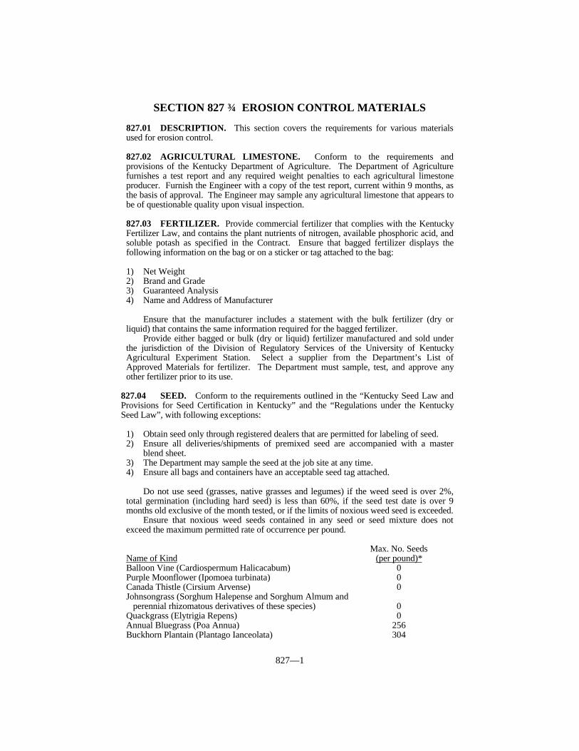
827—1
SECTION 827 EROSION CONTROL MATERIALS
827.01 DESCRIPTION. This section covers the requirements for various materialsused for erosion control.
827.02 AGRICULTURAL LIMESTONE. Conform to the requirements andprovisions of the Kentucky Department of Agriculture. The Department of Agriculturefurnishes a test report and any required weight penalties to each agricultural limestoneproducer. Furnish the Engineer with a copy of the test report, current within 9 months, asthe basis of approval. The Engineer may sample any agricultural limestone that appears tobe of questionable quality upon visual inspection.
827.03 FERTILIZER. Provide commercial fertilizer that complies with the KentuckyFertilizer Law, and contains the plant nutrients of nitrogen, available phosphoric acid, andsoluble potash as specified in the Contract. Ensure that bagged fertilizer displays thefollowing information on the bag or on a sticker or tag attached to the bag:
1) Net Weight2) Brand and Grade3) Guaranteed Analysis4) Name and Address of Manufacturer
Ensure that the manufacturer includes a statement with the bulk fertilizer (dry orliquid) that contains the same information required for the bagged fertilizer.
Provide either bagged or bulk (dry or liquid) fertilizer manufactured and sold underthe jurisdiction of the Division of Regulatory Services of the University of KentuckyAgricultural Experiment Station. Select a supplier from the Department’s List ofApproved Materials for fertilizer. The Department must sample, test, and approve anyother fertilizer prior to its use.
827.04 SEED. Conform to the requirements outlined in the “Kentucky Seed Law andProvisions for Seed Certification in Kentucky” and the “Regulations under the KentuckySeed Law”, with following exceptions:
1) Obtain seed only through registered dealers that are permitted for labeling of seed.2) Ensure all deliveries/shipments of premixed seed are accompanied with a master
blend sheet.3) The Department may sample the seed at the job site at any time.4) Ensure all bags and containers have an acceptable seed tag attached.
Do not use seed (grasses, native grasses and legumes) if the weed seed is over 2%,total germination (including hard seed) is less than 60%, if the seed test date is over 9months old exclusive of the month tested, or if the limits of noxious weed seed is exceeded.
Ensure that noxious weed seeds contained in any seed or seed mixture does notexceed the maximum permitted rate of occurrence per pound.
Max. No. SeedsName of Kind (per pound)*Balloon Vine (Cardiospermum Halicacabum) 0Purple Moonflower (Ipomoea turbinata) 0Canada Thistle (Cirsium Arvense) 0Johnsongrass (Sorghum Halepense and Sorghum Almum and perennial rhizomatous derivatives of these species) 0Quackgrass (Elytrigia Repens) 0Annual Bluegrass (Poa Annua) 256Buckhorn Plantain (Plantago Ianceolata) 304

827—2
Corncockle (Agrostemma Githago) 192Dodder (Cuscuta spp.) 192Giant Foxtail (Setaria Faberii) 192Oxeye Daisy (Chrysanthemum Ieucanthemum) 256Sorrel (Rumex Acetosella) 256Wild Onion and Wild Garlic (Allium spp.) 96
* Seed or seed mixtures that contain in excess of 480 total noxious seeds per pound isprohibited
Wildflower seed shall not be planted until approved by the MCL.
827.05 MULCH MATERIALS. Use material for mulching that is baled wheat, oat,barley, or rye straw, or excelsior wood fibers. Ensure that mulch material is reasonablyfree from weed seeds, stolons, foreign matter, or chaff, and does not contain any Johnson
REQUIREMENTS FOR SEEDSPurity Germination Hard Seed
(Min. %) (Min. %) (Max.%)Grasses Including Allowed
Hard Seed inGermination
Bentgrass (Argrostic palustris) 98 80 -C Bermudagrass, common (Cynodon dactylon) 95 80 -H Bluegrass, Kentucky (Poa pratensis) 90 80 -A Brome, smooth (Bromus inermis) 85 80 -F Canarygrass, reed (Phalaris arundinacea) 90 80 -F Fescue, Chewings (Festuca rubra var. commutata) 95 80 -Y Fescue, meadow (Festuca elatior) 96 85 -
Fescue, red (Festuca rubra) 95 85 -S Fescue, tall (Festuca arundinacca) 95 85 -E Orchardgrass (Dactylis glomerata) 85 80 -E Redtop (Agrostic alba) 90 80 -D Ryegrass, annual, common or Italian (Lotium multiflorum) 97 85 -S Ryegrass, perennial (Lolium perenne) 95 85 -
Lovegrass, Weeping (Eragrostic curvula) 96 75 -N Oat (Avena Sativa) 96 80 -O Rye (Secale cereale) 96 80 -N Timothy (Phleum pratense) 98 80 -C Wheat, common (Triticum aestivum) 96 80 -
H LegumesA Alfalfa (Medicago sativa) 98 85 30F Clover, alsike (Trifolium hybridum) 96 80 35F Clover, ladino (Trifolium repens) 97 80 35Y Clover, white (Trifolium repens) 96 80 35
Crownvetch (Coronilla varia) 96 80 30S Lespedeza, Korean (Lespedeza stipulacea) 97 80 25E Lespedeza, Sevicea (Lespedeza cuneata) 97 80 25E Sweetclover, white (Melilotus alba) 97 85 30D Sweetclover, yellow (Melilotus officinalis) 97 85 30S Trefoil, birdsfoot (Lotus corniculatus) 97 80 35
827—3
Grass, Canada Thistle, Quack Grass, or Nodding Thistle. Ensure that the mulch materialis reasonably bright in color and not musty, moldy, or otherwise of low quality, and doesnot contain chemicals toxic to plant growth.
Use excelsior wood fibers that consist of fibers cut from sound green timber. Ensurethat the cut is made in a manner to provide maximum strength of fiber, but is at a slightangle to the natural grain of the wood so as to cause splintering of the fiber whenweathering occurs. Use fibers with the following approximate physical properties: width0.02 to 0.04 inch, thickness 0.02 to 0.04 inch, and length 4 to 6 inches.
827.06 ASPHALT MATERIALS FOR MULCH. Use either SS-1, SS-1h, Primer L,AE-60, MC-30, or MC-70, all conforming to Section 806 except that the Department maywaive retesting as provided by Subsection 806.04. The Engineer may reject asphaltmaterials that fail to disperse properly or otherwise fail to provide satisfactory results.
827.07 EROSION CONTROL BLANKET. Use a machine constructed curled woodfiber mat with two-sided netting or a straw and coconut fiber combination mat with two-sided netting. Ensure the blanket is smolder resistant without the use of chemicaladditives.
A) Dimensions. Furnish in strips either 4 or 8 feet wide and at least 50 feet long.B) Weight.
1) Curled Wood Fiber. Ensure a minimum mass per unit area of 0.91 poundsper square yard according to ASTM D 5261.
2) Straw/Coconut Fiber. Ensure a minimum mass per unit area of 0.78 poundsper square yard according to ASTM D 5261.
C) Fill. Ensure the fill is evenly distributed throughout the blanket.
1) Curled Wood Fiber. Use curled wood fiber of consistent thickness with atleast 80 percent of its fibers 6 inches or longer in length.
2) Straw/Coconut Fiber. Use a minimum of 30 percent coconut fiber evenlydistributed throughout agricultural straw.
D) Netting. Use photodegradable extruded plastic mesh or netting, with amaximum spacing width of one inch square, on both sides of the blanket. Securethe netting by stitching or other method to ensure the blanket retains its integrity.
E) Staples. Use steel wire U-shaped staples with a minimum diameter of 0.09inches (11 gauge), a minimum width of one inch, and a minimum length of 6inches. Use a heavier gauge when working in rocky or clay soils and longerlengths in sandy soils.
F) Performance.
1) Shear Stress. Ensure the blanket can sustain a minimum shear stress of 2.00pounds per square foot without physical damage or excess erosion (> 0.5inches soil loss) during a 30 minute flow event when tested according toASTM D 6460.
2) C Factor. Ensure the ratio of soil loss from protected slope to ratio of soilloss from unprotected is less than 0.25 for a slope of 1.5:1 when testedaccording to ASTM D 6459.
827.08 TEMPORARY SILT FENCE.
A) Posts. Use either hardwood or steel greater than 4 feet in height. For hardwood,provide a minimum 1 1/2-inch by 1 1/2-inch cross section that is straight enough toprovide a fence without noticeable misalignment. For steel, provide a 1 1/4- inch byone-inch T-section with projections to fasten wire and fabric in position.

827—4
B) Woven or Welded Wire Fabric. Conform to Section 816 or 811. Provide fabricwith a minimum height of 2 feet 8 inches. Require at least 6 horizontal wires spaced6 1/4 inches or closer with the top and bottom wires 0.134 inch or larger and all otherwires 0.1 inch or larger. Require 0.1 inch or larger vertical wires spaced 12 inches orcloser.
C) Geotextile Fabric. Conform to AASHTO M 288 for temporary silt fence. Providefabric with a height of 3 feet.
D) Fasteners. Use No. 9, one inch long wire staples and/or fabric ties that conform toSubsection 816.06.
827.09 NETTING AND STAPLES. Conform to the Standard Drawings and thePlans. The Engineer may accept netting and staples on the basis of visual inspection.
827.10 TOPSOIL. Topsoil is the portion of the soil profile defined technically as the“A” horizon by the Soil Science Society of America. Use loose, friable, topsoil that is freeof stones 1 inch or greater in overall dimensions, admixture of subsoil, refuse, stumps,roots, brush, weeds, and other material that prevent the formation of a suitable seed bed. Before stripping the topsoil, inspect for existing vegetation. Do not use topsoil from siteshaving Johnson Grass, Canada Thistle, Quack Grass, Nodding Thistle, or excessiveamounts of other noxious weeds, or their rhizomes. The Department will sample the soiland determine the textural classification according to the US Department of Agriculturesystem, the particle size according to KM 64-519, the organic content according to KM64-243, and the pH according to ASTM D 4972. Acceptable topsoil composition is:
Clay 40% maximumSilt 70% maximumSand 60% maximumOrganic Material 2% minimum, 10% maximumpH 6.0 minimum, 7.0 maximum
827.11 SOD. Use sod that is either well-rooted Kentucky Bluegrass or Tall Fescue sod.However, obtain the Engineer’s approval prior to using Tall Fescue sod in residentialareas. Use sod that is completely free from noxious weeds and reasonably free from otherobjectionable grasses and weeds and stones or other foreign materials detrimental to thedevelopment and future maintenance of the sod. Obtain sod from sources that are coveredwith grass having a maximum height of 3 inches. Obtain approval of the selected sourceprior to cutting.
828—1
SECTION 828 MASONRY COATING MATERIALS
828.01 DESCRIPTION. This section covers requirements for materials to be used assurface finishes for designated surfaces of cement concrete structures. The masonrycoatings must hide form marks, patches, and other minor irregularities and preventdeterioration, spalling, and other damage to the concrete due to the action of the weatherand deicing chemicals.
828.02 APPROVAL. Select masonry coatings from the Department’s List of ApprovedMaterials. Use a material that is readily recognizable by its name, trademark, container, orother feature. Conform to the Department’s testing criteria to be placed on or remain onthe Department’s List of Approved Materials.
For initial approval submit representative samples, color chip(s), and duplicate copiesof certified test reports to the Division of Materials for review and approval. Anindependent testing laboratory acceptable to the Department shall perform the testsdescribed herein on representative samples of the material. Tests listed herein are theminimum testing requirements to be met. When requested in writing, the Engineer mayaccept materials based on conformance to the same type of test but differing on minorprocedural points. Attach copies of test procedures which differ from those stated herein. In addition to the material, provide brochures or booklets containing detailed instructionsand explanatory remarks about surface preparation, application procedures, and otherpertinent operations.
828.02.01 Freeze-Thaw Test. Cast and cure 3 concrete specimens no less than 4 by4 by 6 inches. Moist cure specimens for 14 days and then dry in room air at 60 to 80 °Ffor 24 hours before applying masonry coating. Ensure that there is no excessive oil onspecimen forms. Coat sides of specimens (brush permitted) according to themanufacturer’s directions at a rate of 50 ± 10 square feet per gallon and cure at roomtemperature for 48 hours; after which:
1) Immerse in water at room temperature 60 to 80 °F for 3 hours and remove.2) Place in cold storage at -15 °F for one hour and remove.3) Thaw at room temperature 60 to 80 °F for one hour.4) Repeat steps 1), 2), and 3) to complete a total of 50 cycles. At the end of 50
cycles of the Freeze-Thaw Test, ensure that the coated specimens shows novisible defects.
828.02.02 Accelerated Weathering. Test according to ASTM D 822. Apply at anapplication rate of 50 ± 10 square feet per gallon. Test for 335 hours in an Atlas Type XWSunshine Arc Weatherometer or for 500 hours in an Atlas Type DMC Enclosed VioletCarbon Arc Weatherometer or equivalent. Perform the test in 120-minute cyclesconsisting of 102 minutes of light and 18 minutes of light and demineralized water. At theend of the exposure test, ensure that there is no checking, cracking, or loss in film integrity,and no other film defects. Ensure that the coating shows no more than very slight colorchange.
828.02.03 Salt Spray Resistance. Apply the masonry coating to concrete at a rate of50 ± 10 square feet per gallon, and test the coating according to ASTM B 117. Expose thecoating to a 5 percent sodium (salt) solution for 300 hours, and maintain it at 90 ± 2 °Fduring the period of exposure. Ensure that it shows no loss of adhesion or deterioration atthe end of the 300 hours.
828.02.04 Fungus Growth Resistance. Ensure that the masonry coating passes afungus resistance test as described by Federal Specification TT-P-29. After a minimumincubation period of 21 days, ensure that no growth is exhibited on the coating.
829—1
SECTION 829 —HARDWARE FOR TIMBER STRUCTURES
829.01 GENERAL. Use only black nails, spikes, bolts, dowels, washers, and lagscrews.
829.02 BOLTS. Use machine bolts having square heads and nuts, and ensure thatscrew threads make a close fit in the nuts. Furnish machine bolts, drift-bolts, and dowelsof either wrought iron or medium steel. Designate the weight of bolts as “AmericanStandard Regular.”
829.03 WASHERS. Furnish washers that either are cast O-gee or malleable castings orare cut from medium steel or wrought-iron plate, as specified in the Contract.
829.04 NAILS. For nails, use cut or round wire of standard form. Furnish cut or wirespikes, or boat spikes, as specified in the Contract.
830—1
SECTION 830 RETROREFLECTIVE MATERIALS
830.01 DESCRIPTION. This section covers the requirements for retroreflectivematerials for use in delineators, barricades, traffic drum channelizing tapes, cone collars,signs, and for other applications as required.
830.02 GENERAL REQUIREMENTS. Ensure that all materials and prepared signfaces are free from cracks, tears, ridges, humps, discoloration, or other objectionableblemishes. When furnishing materials for the Department or its agent to fabricate signs,ensure compatibility with the manufacturer’s recommended fabrication procedures and therequirements of this section. The Department will reject material that prevents successfulfabrication.
830.02.01 Delineators. Provide the size and shape specified in the Contract. Providedelineators that exhibit no significant change in shape or appearance when subjected to theheat resistance test.
A) Type B. Furnish Type III, Class 1 retroreflective sheeting attached to a non-corrosive metal backing or approved equal rigid substrate.
B) Type C. Furnish Type III, Class 1 retroreflective sheeting attached to a flexibledelineator post.
830.02.02 Barricade Sheeting. Conform to ASTM D 4956, Type III, Class 1.
830.02.03 Traffic Drum Channelizing Tape. Conform to ASTM D 4956, Type III,Class 1 or 3.
830.02.04 Cone Collars. Conform to ASTM D 4956, Type VI, Class 1 or 3.
830.02.05 Roll Up Sign Sheeting. Conform to requirements detailed in the List ofApproved Materials.
830.02.06 Sign Sheeting. Provide permanent sign sheeting that conforms to ASTM D4956 and has completed a 3-year evaluation on the National Transportation ProductEvaluation Program (NTPEP) test decks. Provide permanent fluorescent sign sheeting thatconforms to the retroreflectivity requirements detailed in the List of Approved Materialsand has completed a 3-year evaluation on the NTPEP test decks. Provide temporary signsheeting, used for work zone applications, that conforms to the retroreflectivity criteria inthis section and has completed 12 months on the NTPEP test deck. Use sheeting materialsthat present a finished surface suitable for receiving stenciled messages, paint overlays, orfilm overlays. Provide only reteoreflective sign sheeting materials that conform to FederalSpecification L-S-300C for solvent, heat, cold, and humidity resistance.
The List of Approved Materials contains all approved retroreflective sheetingproducts. The List of Approved Materials also contains the applications for the specificsheeting types.
830.03 FIELD PERFORMANCE. The using agency is responsible for requiring thedating of all signs at the time of installation. The Department will begin the fieldperformance obligation period based on that date.
The Department will consider the retroreflective sheeting defective if any of thefollowing conditions are observed:
830—2
1) When viewed from a moving vehicle under normal day and night drivingconditions, it has deteriorated due to natural causes to the extent that the sign isineffective for its intended purpose.
2) It no longer meets the minimum criteria for retained retroreflective afteratmospheric exposure
3) Fluorescent sheeting fails to retain 80 percent of the retroreflective requirementsdetailed in the List of Approved Materials.
830.04 WARRANTY. When the Engineer determines that the retroreflective signsheeting supplied and used according to the manufacturer’s recommendations have notmet field performance requirements, the manufacturer shall cover restoration costs asfollows for sheeting:
1) Permanent Sheeting. Within the first 7 years after application, replace thesheeting and cover the cost of materials and labor required to restore the signsurface to its original effectiveness including stenciled messages, paint overlays,or film overlays. Within the 8th through 10th year after application, replace thesheeting required to restore the sign surface to its original effectiveness includingstenciled messages, paint overlays, or film overlays.
2) Temporary Sheeting. Within 3 years after application, replace the sheetingrequired to restore the sign to its original effectiveness including stenciledmessages, paint overlays, or film overlays.
830.05 PACKAGING. Ensure that all materials are suitably and substantiallypackaged and have the name and address of the manufacturer or vendor, contract orpurchase order number, kind of material, trade name, date of manufacture, lot and runnumber, color, and net contents plainly marked on each package or container. Ensure thatif stored under normal conditions, the retroreflective material as furnished is suitable foruse for a minimum period of one year.
830.06 SAMPLING. For the purpose of sampling, a shipment consists of the amountof material received in one delivery even though it may represent only partial delivery ofthe Contract quantities. The Department will sample according to the Manual for FieldSampling and Testing.
830.07 TESTING AND ACCEPTANCE. Furnish copies of actual passing test reportsfor retroreflective sheeting. Provide certifications from the sign supplier that the materialfurnished is the same represented by the test reports.
Use only retroreflective sign sheeting from the List of Approved Materials. Only usebarricade sheeting, traffic drum channelizing tape, and cone collars when supplied withappropriate certifications and test reports.
831—1
SECTION 831 — CONSTRUCTION ZONE TEMPORARYMARKING TAPES
831.01 DESCRIPTION. This section covers pavement marking material designed toprovide reflective delineation in construction zones. This section covers the followingtypes of marking material:
A) Type A. Non-removable Pavement Marking Tape.B) Type B. Removable Pavement Marking Tape.
831.02 REQUIREMENTS.
831.02.01 Manufacture. Use a material consisting of a weather and traffic-resistantreflective film on a backing precoated with a pressure-sensitive adhesive.
831.02.02 Adhesive. Use a precoated pressure-sensitive adhesive that does notrequire a liner or activation.
831.02.03 Application Properties. Ensure that the material adheres to asphalt andconcrete surfaces, when applied according to the manufacturer’s recommendations, at orabove surface temperatures of 40 °F. Ensure that the material does not require anyprotective devices such as traffic cones or barricades after application.
831.02.04 Conformability and Thickness. Use material that is thin, flexible,formable, and remains conformed to the texture of the pavement surface followingapplication. Ensure that the thickness of the material furnished is within 2 mils of thethickness of the material submitted for initial testing for placement on the Department’sList of Approved Materials. Use tape with a minimum width of 4 inches.
831.02.05 Miscellaneous Requirements. Ensure that the supplied material is ofgood appearance, free from cracks, with edges true, straight, and unbroken. Make thematerial available in rolls with no more than 3 splices per 50 yards of length. Package thematerial according to accepted commercial standards. Ensure that the supplied material iscapable of being stored at temperatures up to 100 °F for a period of one year after purchasewithout adversely affecting the physical properties stated in this section.
831.02.06 Performance. The AASHTO Regional Test Facility and the NationalTransportation Product Evaluation Program will perform field performance testing. Theywill perform testing at approximately one-year intervals, and will require a 6 monthminimum testing period. Procedures will be according to the AASHTO Regional TestFacility and the National Transportation Product Evaluation Program. They will evaluateall tapes on both asphalt and JPC pavement. The performance criteria is included in theDepartment’s List of Approved Materials.
831.03 APPROVAL. Use materials that are on the Department’s List of ApprovedMaterials. To be placed on the approved list, tapes must conform to all requirements ofthis section. Ensure that each shipment of tape to a project is accompanied by a statementfrom the manufacturer indicating the brand or trade name of the tape. The Departmentreserves the right to sample and test materials actually furnished at any time.
The Department will remove materials from the list if the material fails to beacceptable in subsequent field performance testing or the material’s composition haschanged since the original approval.
832—1
SECTION 832 SIGN POSTS
832.01 GENERAL. Furnish Type I and II posts. Type I posts are square tubular posts. Type II posts are channels. Provide all posts in lengths as specified in one foot incrementswith a tolerance of ± one inch. The Department may require anchor plates for either type.
Ensure that posts are straight, smooth, and free from any defects affecting theirstrength, durability, or appearance. Ensure that all holes and ends are free from burrs andsharp edges and that ends are cut square.
832.02 TYPE I POSTS. Use hot rolled carbon sheet steel of structural quality thatconforms to ASTM A 1011, Grade 50. Yield strength after cold-forming is 60,000 psiminimum.
832.02.01 Fabrication. Fabricate the post from square tube formed of steel, rolled tosize and welded directly in the corner by high frequency resistance welding and externallyscarfed to agree with corner radii. Provide the following sizes:
Provide 7/16-inch diameter holes on the centerline of all 4 sides, space on one-inchcenters along the entire post length beginning 1 inch from the top. Ensure holes are in truealignment and opposite each other directly and diagonally.
Ensure consecutive sizes of square tubes will freely telescope for 10 feet or more oftheir length without the necessity of matching any particular face to any other face.
832.02.02 Finish. Conform to ASTM A 653, G90, Structural Quality, Grade 340,Class 1. Galvanize both the interior and the exterior of the post. Coat the corner weldwith zinc after the scarfing operation. Coat the steel with a chromate conversion coatingand a clear organic polymer topcoat.
832.02.03 Tolerances. The Department may reject material falling outside any ofthe following tolerances:
A) Outside Dimensions. ± 0.008 inch. Measure at least 2 inches from the end ofthe tube.
B) Wall Thickness. ± 0.008 inch.C) Holes. ± 0.016 inches in diameter.D) Convexity and Concavity. Ensure that no sides exceed ± 0.1 inch. Measure in
the center of the flat side relative to the corner.E) Square (1 3/4-inch posts). Ensure sides are 90 degrees to each other within
± 0.01inch.F) Square (2-inch posts). Ensure sides are 90 degrees to each other within ± 0.012
inch.G) Twist. Ensure twist does not exceed 0.02 inch in any one-foot length.H) Straight. Ensure deviation does not exceed 0.02 inch in any one-foot length.I) Corner Radii. 5/32 ± 0.016 inch.
832.03 TYPE II. Use hot wrought steel conforming to the physical properties of ASTMA 499-89, Grade 60, and conforming to the chemical requirements of ASTM A 1 for railsof nominal weight between 28.4 and 38 pounds per foot.
The Contractor may request to furnish posts made of material not complying with thespecified properties. If desired, submit the written request for approval and include a
Outside Dimensions(in.)
Corner Radii(in.)
Thickness(in.)
Weight(lb/ft)
1 3/4 by 1 3/4 5/32 0.08 1.72 by 2 5/32 0.08 2.0
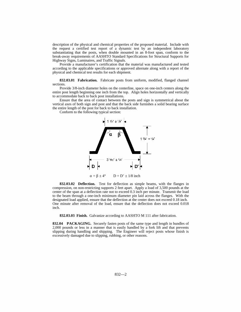
832—2
description of the physical and chemical properties of the proposed material. Include withthe request a certified test report of a dynamic test by an independent laboratorysubstantiating that the posts, when double mounted in an 8-foot span, conform to thebreak-away requirements of AASHTO Standard Specifications for Structural Supports forHighway Signs, Luminaires, and Traffic Signals.
Provide a manufacturer’s certification that the material was manufactured and testedaccording to the applicable specifications or approved alternate along with a report of thephysical and chemical test results for each shipment.
832.03.01 Fabrication. Fabricate posts from uniform, modified, flanged channelsections.
Provide 3/8-inch diameter holes on the centerline, space on one-inch centers along theentire post length beginning one inch from the top. Align holes horizontally and verticallyto accommodate back to back post installations.
Ensure that the area of contact between the posts and sign is symmetrical about thevertical axes of both sign and post and that the back side furnishes a solid bearing surfacethe entire length of the post for back to back installation.
Conform to the following typical section:
α = β ± 4° D = D’ ± 1/8 inch
832.03.02 Deflection. Test for deflection as simple beams, with the flanges incompression, on non-restricting supports 2 feet apart. Apply a load of 3,500 pounds at thecenter of the span at a deflection rate not to exceed 0.3 inch per minute. Transmit the loadto the beam through a one-inch minimum diameter pin laid across the flanges. With thedesignated load applied, ensure that the deflection at the center does not exceed 0.18 inch. One minute after removal of the load, ensure that the deflection does not exceed 0.018inch.
832.03.03 Finish. Galvanize according to AASHTO M 111 after fabrication.
832.04 PACKAGING. Securely fasten posts of the same type and length in bundles of2,000 pounds or less in a manner that is easily handled by a fork lift and that preventsslipping during handling and shipping. The Engineer will reject posts whose finish isexcessively damaged due to slipping, rubbing, or other reasons.
833—1
SECTION 833 SIGN SUBSTRATES
833.01 ALUMINUM.
833.01.01 Panel Signs. Conform to ASTM B 221, Alloy 6063-T6. Fabricate signsfrom 12-inch wide extrusions and, if specified, compatible 6-inch wide extrusions. Whena 6-inch extrusion is specified, use it as the bottom panel of the sign. Typical crosssections and minimum weights per foot are specified in the Plans. Use compatible sideextrusions on all sign edges. Prepare surfaces of extrusions composing the sign face toreceive retroreflective background material according to the extrusion and retroreflectivematerial manufacturers’ recommendations. Provide all remaining surfaces of extrusionsand side extrusions with a soft matte finish.
833.01.02 Sheeting Signs. Conform to ASTM B 209, Alloy 6061-T6 or 5052-H38. Fabricate signs of the size and shape specified. Provide a thickness of 125 mils inch if anysingle edge dimension of the sign exceeds 3 feet. If no single edge dimension exceeds 3feet, provide a thickness of 80 mils. Prepare the side of the sheet to be used as the signface to receive retroreflective background material according to the sheeting andretroreflective material manufacturer’s recommendations.
834—1
SECTION 834 ROADWAY LIGHTING MATERIALS
834.01 WIRING. For all multiple circuit roadway lighting wires use single-conductorAWG copper of sizes specified in the Plans. Use No. 12 AWG copper wire as leads frompole bases or junction boxes to ballast terminals. Use stranded wire, except for groundwires. Ensure that all insulation for No. 8 or larger wire is Type USE (UL rated). Insulation for No. 10 or smaller wire shall be Type THW or THWN. Plainly mark all wireand cable according to the NEC. Use copper grounding conductors sized as specified bythe NEC. Install copper service entrance conductors on the service poles sized andinsulated as specified by the NEC.
834.02 DUCTED CABLE.
A) Cable. Use stranded annealed copper cable conforming to ASTM B 8 and ASTM B33 for operation at 600 volts maximum. Use material that conforms to either theapplicable requirements of ICEA Standard S-19-81, with thermoplastic insulation ofGRS-rubber base conforming to Appendix K(A) of ICEA and listed by UL as TypeUSE for direct burial; or the application requirements of ICEA Standard S-66-524,with thermo-setting insulation of cross link polyethylene conforming to therequirement of Column “A” of ICEA and listed by UL as Type USE. Use cable thatis preinstalled in the duct.
B) Duct. Use polyethylene duct with a minimum tensile strength of 3,100 psi forsecondary cable underground. Provide for 40 percent maximum fill. Conform toASTM D 3485.
834.03 CONDUIT. Except in load bearing areas, use UL rated, schedule 40, PVCconduit. In load bearing areas, use rigid steel conduit that is galvanized inside and out.For underground installation, use conduit of 1 1/4-inch or larger nominal diameter, exceptuse 3/4-inch PVC conduit in the pole bases.
834.04 FUSED CABLE CONNECTOR KIT. Connect lighting fixtures to the feedcircuits with fused cable connector kits. Place each kit in a transformer base, junction box,handhole, or other place as specified in the Contract. Ensure that the fused connector kitcan be repeatedly disconnected without damage to the watertight seals and terminals orwithout reducing the conductivity below specifications. Provide a fused connector kitdesigned to break away without damage.
Use a fused connector kit that completely encloses and protects the fuse againstdamage from water and weather. Use a spring loaded contact between the fuse andfuseholder. Ensure that the springs are not a part of the current carrying circuit. Ensurethat line and load side terminals of the fused connector kit positively connect to theconductors. Insulate and waterproof the terminals according to the manufacturer’srecommendation. Construct the load side housing to retain the fuse when disconnected,and permanently mark it “LOAD” or “LOAD SIDE”.
Use high interrupting capacity type fuses with a rating of 6 amperes. Use 13/32 by 11/2-inch fuses that are rated for 600 volts. Use fuses that protect circuits having a faultcurrent capacity of up to 100,000 amperes AC. Use fuses tested to carry 110 percent oftheir rated capacity and that open at 135 percent in one hour or less.
834.05 LIGHTING STANDARDS. For the design of and materials for all lightingstandards, conform to the AASHTO Standard Specifications for Highway Signs,Luminaires, and Traffic Signals, except as follows. For breakaway signs, and luminairesupports, conform to the breakaway requirements in the AASHTO Standard Specificationsfor Highway Signs, Luminaires, and Traffic Signals, 1985 edition as amended by the“1988 Interim Revisions”, with the modification that the maximum allowable change invelocity is 16 feet per second. Provide lighting standards that consist of a tapered polehaving a base affixed to the lower end, a bracket arm (if required), and a transformer base.

834—2
Furnish an opening near the top of the pole to provide for a cable entrance from the pole tothe bracket arm to provide a smooth cable guide for wiring. Equip the top of the pole witha removable cap. Secure a one-piece anchor base to the lower end of the pole. Provide thisbase with 4 slotted holes to receive the anchor bolts and 4 tapped holes for securing thebolt covers. Provide 4 removable bolt covers with each base.
Use single member bracket arms for 4 and 6-foot mast arm assemblies. Use single ordouble member bracket arms for 8-foot mast arm assemblies. Use double pipe assembliesfor 10, 12, and 15-foot mast arm assemblies. Double pipe assemblies consist of upper andlower members securely joined by means of vertical struts. Provide the pole end of thebracket arm with a cast or plate footing or clamp for positioning the assembly on the pole.
Galvanize the steel structures after fabrication.Ensure that the pole manufacturer provides permanent marking on the pole base or
other suitable location, giving the pole design number and other identification data so thepoles may be compared with material brochures or drawings.
Provide each pole with a suitable handhole to allow access to the pole formaintenance of wiring inside the pole.
834.06 ANCHOR BOLTS. Fabricate anchor bolts from steel having a minimum yieldstrength of 50,000 psi. Provide L-shaped anchor bolts with a minimum length of onemeter, a minimum diameter of one inch, and the horizontal leg at least 4 inches long. Themanufacturer shall specify the correct dimensions; but in no case shall they be less than thedimensions specified above. Provide at least 6 inches of threads and 8 inches ofgalvanizing at the top of the vertical leg. Provide each anchor bolt with 2 galvanized hexnuts. Submit mill test reports on anchor bolts. Protect anchor bolt threads from damageduring shipping.
834.07 TRANSFORMER BASES. Conform to the AASHTO Standard Specificationsfor Structural Supports for Highway Signs, Luminaires and Traffic Signals. Ensure thateach base has the following minimum outside dimensions: 17 inches high, 15 by 15-inchsquare bottom and 12 by 12-inch square top. Ensure that bases have a trapezoidal doorwith the following minimum dimensions: 11 inches high, 9 inches across the bottom, and7.5 inches across the top. Construct the door of a high density polyethylene material in acolor that matches the base. Provide each base with 4 loose bearing plates (anchorwashers) and nuts to fasten the base to the anchor bolts. Fasten each transformer base tothe base flange of the pole with 4 loose galvanized bearing plates and 4 galvanized steelconnecting bolts and nuts. Use connecting bolts of the same diameter and strength as theanchor bolts. Submit mill test reports on the connecting bolts. The manufacturer shallspecify the bolt circle and physical dimensions of the base bottom to ensure a properfoundation fit. Provide each transformer base with a 1/2-inch 13 UNC tapped hole orother suitable provisions for grounding purposes.
834.08 MARKERS FOR BURIED CONDUIT. Use 36 by 4 by 4-inch concrete postsreinforced with 4 No. 3 deformed steel bars. The Department will allow the use ofstandard rural right-of-way markers in lieu of conduit markers.
834.09 CONCRETE. Conform to Subsection 601.02 and 601.03. Use Class Aconcrete.
834.10 PAINTS. Use commercially available rust inhibiting primer for the prime coat. Use aluminum paint conforming to AASHTO M 69, or equal, for the intermediate andfinish coats.
834.11 BALLASTS. Provide only high-pressure sodium luminaire ballasts that operatein a single circuit of the specified voltage ± 10 percent.
834.12 LUMINAIRES. Provide IES distribution as specified in the Contract; 2-inchslip-fitter mounting; and constant wattage type transformers.
834—3
Type A - 100 watt high-pressure sodium horizontal roadway luminairesType B - 150 watt high-pressure sodium horizontal roadway luminairesType C - 250 watt high-pressure sodium horizontal roadway luminairesType D - 400 watt high-pressure sodium horizontal roadway luminaires
Use luminaires that provide light levels conforming to AASHTO’s An InformationalGuide for Roadway Lighting. When submitting brochures for suggested luminaires,include iso lux curves, IES type distribution, lamp lumens, and typical ballast factor usedfor each type of luminaire. Submit the photometric data in IES format on an IBMcompatible 3 1/2-inch floppy disk to the Central Office, Division of Traffic. Include withthe submittal a point of contact and phone number to answer technical questions about theluminaire.
834.13 LAMPS. Provide only high-pressure sodium lamps with the followingminimum initial light output:
Type A - 9 500 lmType B - 16 000 lmType C - 25 000 lmType D - 50 000 lm
834.14 MAGNETIC CONTACTORS AND CONTROL TRANSFORMERS. Provide only magnetic contactors that are 2 pole, sized as specified in the Contract, andhave a 120 volt coil. Protect each contactor coil by a 15 amp fuse. Equip contactors withcontrol switches for both automatic and manual actuation. Provide photoelectric switchesfor automatic actuation. Use photoelectric controls that are solid state cadmium sulfidetype designed for use in 120 volts 60 Hz circuits and rated for 1,000 watts resistive load. Use photoelectric controls with built-in surge protection and designed to provide an outputcircuit closure when photoelectric control components fail. Provide photoelectric controlsand mounting bases that are twist-lock type. Provide 2 pole, double throw switches thatmanually actuate. Ensure that each switch has minimum rating of 125 volts, 15 amperes.
Use control transformers that are 1 KVA, single phase, 240/480 volt primary,120/240 volt secondary, dry type, 60 Hz, with primary winding isolated from secondarywinding. Use transformers that are capable of indoor or outdoor installation and have amaximum temperature rise of 99 °F at 104 °F ambient temperature.
834.15 DISTRIBUTION TRANSFORMERS. Equip all distribution transformerswith 2, 2.5 percent taps above and below rated primary voltage. Provide transformers thatare protected by a primary lightning arrester with an indicating fuse cutout of the voltageand amperage as specified in the Plans.
834.16 SECONDARY LIGHTNING ARRESTERS. Provide only secondarylightning arresters designed for use with the specified voltage and rated at 0-650 voltsRMS.
834.17 WEATHERPROOF ENCLOSURES. Fabricate enclosures from 125-mil orthicker natural finished aluminum. Provide enclosures with a No. 2 Corbin lock and keys.Install a 120 VAC GFI duplex receptacle in the enclosure with a separate 20 amp breaker.
834.18 GROUND RODS. Provide only composite shaft ground rods consisting of apure copper exterior that has been inseparably molten welded to a steel core. Use rodswith a minimum diameter of 1/2 inch and a minimum length of 8 feet. Equip the rodswith copper or bronze clamps.
834.19 WOOD POLES. Use Class 4 poles, of the length specified in the Contract,conforming to Subsection 820.
835—1
SECTION 835 TRAFFIC CONTROL DEVICES
835.01 DESCRIPTION. This section defines minimum acceptable design andoperational standards for traffic control devices used in the Commonwealth.
835.02 TIME CLOCKS. Use time clocks that are solid state, microprocessor basedunits with one to 4 relay outputs rated at 10 amps, 115 VAC resistive load. Connect allrelay contacts and clock power through a 16 pin circular plastic connector (Amp#520258-3 or approved equal). Pin designations are as follows:
Pin No. Function Pin No. Function1 Line 9 #4 Com2 Neutral 10 #1 N.O.3 Ground 11 #3 Com4 #1 Com 12 #3 N.C5 #1 N.C 13 #3 N.O.6 #2 Com 14 #4 N.C.7 #2 N.O. 15 #4 N.O.8 No Con. 16 #2 N.C.
Operate clocks with a supply voltage from 95 to 135 VAC, 60 Hz at temperaturesfrom -29 to + 165 °F.
Supply backup power for the clock with a battery or capacitor. Ensure that backuppower maintains time keeping and program steps for at least 48 hours.
Enter all programming through the keyboard. Ensure that programming featuresinclude at least 32 program steps. Ensure that each step shall program a single relayoutput by hour and minute and allow a single day of week, Monday through Friday orSaturday and Sunday to be set. Provide clocks that have automatic daylight savings timeadjustment as default with a daylight savings time override option controlled from thekeyboard. Provide clocks that have manual override capability for each relay. Provideclocks that have a self test function which exercises relay outputs. Ensure that units areenclosed in a durable case that can mount on a vertical surface. Supply each unit with afemale mating harness with 3-foot wires. Wire the harnesses for the number of relays usedin the clock. Label each wire one foot from the plug with permanent non-fading wirelabels indicating the wire function.
835.03 PEDESTRIAN PUSHBUTTON DETECTORS. Provide a pedestriandetector that consists of a single plunger push button control switch with a 2 1/4-inch(minimum) chrome plated mushroom shaped plunger. Provide a 5-A (minimum), 110VAC switch with 2 circuit (NO/NO) slow make contacts. Ensure that pushing of thebutton closes both NO circuits. Use a switch body that is die cast and painted with a blackwrinkle finish paint. Include a neoprene gasket for sealing the switch body to theenclosure.
835.04 EQUIPMENT TESTING. The Department requires that each purchasedindividual cabinet, controller, conflict monitor, modem, and loop amplifier isenvironmentally tested. At a minimum, test each unit purchased according to “TrafficSignal Control Equipment Specifications” by the California Department of Transportation. The manufacturer is free to suggest additional tests or variations in the above proceduresthat may be part of an existing quality control program.
A representative of the Department may travel to the testing site to verify that theenvironmental testing is being carried out properly and to observe manufacturing practicesused at the factory. The manufacturer shall submit a proposed testing procedure andschedule 30 calendar days in advance for evaluation by the Department. Ensure that the
835—2
test procedures, environmental chambers, automatic test equipment, display boards, powersupplies, and controls are described in detail. Resolve any problems in the testingprocedure before the representative arrives.
Test cabinets at ambient room temperature. Use an automatic or semi-automaticmethod for checking cabinet wiring between equipment harnesses.
835.05 SIGNALS AND BEACONS.
835.05.01 Fittings and Mounting. Supply all traffic control signals, beacons, andlane control signals, unless otherwise specified, with necessary fitting including wireentrance fittings and swivel type balance adjuster for span wire mounting. Design wireentrance fitting to prevent entrance of water when using normal drip loops. Galvanize orcadmium plate span wire clamps and bolts.
Ensure that the total loose play rotational tolerance between span wire clamp and wireentrance fitting, with swivel adjuster assembled, is not more than 3 degrees.
Use mounting arms and brackets made of 1 1/2-inch standard metal IPS pipe. TheDepartment will allow cast or fabricated bottom brackets.
Ensure that signals are adjustable, and arrange them so that each face may be rotatedto and positively locked within not more than 5 degrees of any position in the horizontalplane. Use a separate locking ring mating with serrations cast or molded into the signalhousing. Do not use serrations cast into the wire outlet body. Use a locking ring designedwith a minimum of 2 pins or tabs to mate with corresponding holes or notches in the wireoutlet body. Use locking rings that are machined to provide sharp, well formed serrationsthat exactly match the serrations in the signal housing.
835.05.02 Housings. Provide metal housings cast from a non-ferrous, non-corrosivealuminum alloy. Use parts that are fitted with rubber or neoprene type gaskets to provideweather tight seals. Use housing sections of the same type and make of manufacturer thatare interchangeable. Reinforce tops and bottoms to which supporting attachments arefastened to prevent breakage from vibration and shock.
Use polycarbonate signals that are the same in appearance as cast aluminum signals,except mold the housings, doors, and visors from polycarbonate resin to withstand a 70foot-pound impact without fractures or permanent deformation. Ensure that the color ishomogeneous throughout.
Use doors of the same material as the housing. Ensure that doors are suitably hingedand held securely to the housing by simple locking devices, which do not require tools ofany kind for opening. Use stainless steel hinge pins, lens clips, etc.
835.05.03 Optical Units. Each optical unit is a complete assembly of lampreceptacle, reflector, cover glass or lens, and door with all necessary supporting parts andwith a single signal indication. Conform in all respects, except as further restricted by thissection, to the standards of the Institute of Traffic Engineers (ITE).
Provide incandescent illuminated optical units that contain a heat resistant lampreceptacle positioned to provide a light center at the focal point of the reflector. Usereflectors that are “ALZAK” process coated aluminum or other approved equal. Use a650-watt standard traffic signal lamp in an 8-inch traffic signal, 9-inch pedestrian signal,or 12-inch one-section pedestrian signal. Use a 1 950-lumen standard traffic signal lampin a 12-inch traffic signal, lane control signal, or 12-inch pedestrian signal.
Construct and mount optical units to provide easy access for all maintenance andrepairs including wiring within the signal housing. Design optical units so that the use oftools of any kind are not required for replacing signal lamps.
Wire and connect each lamp receptacle to a suitable terminal block within the signalhousing with minimum No. 18 AWG, 194 °F, 600 volt, color-coded, stranded fixture wire. Do not use braided wire. Locate the terminal block in the second section from the top inmulti-section faces.
Use glass lenses. Ensure that lenses of the same nominal diameter areinterchangeable regardless of manufacturer.

835—3
Each signal face contains one or more complete optical units in suitable housings forcontrol in one direction only and is designated as one-section, 2-section, 3-section, etc.
835.05.04 Signal Heads. Each signal head contains one or more signal faces and isdesignated as one-way, 2-way, 3-way, etc.
One-section signals are standard flashing beacons. For one-way and two-wayflashing beacons, supply signal heads with amber or red lenses as specified in theContract. Mount signals with 2 or more sections vertically with indications positionedaccording to the MUTCD.
Fit each optical unit with a visor or hood. Provide combination or tunnel type visorsthat enclose at least 80 percent of the lens circumference for amber lenses. Supplystandard visors that enclose at least 50 percent of the lens circumference for all red orgreen lenses. Supply visor lengths that are approximately the same as the lens diameterand designed to minimize sun phantom. Attach hoods with screws. Do not use snap inhoods.
Ensure that 8-inch signals display circular indications of not less than 7 3/4 inches indiameter. Ensure that 12-inch signals display circular indications of not less than 11 1/2inches in diameter.
Ensure that signal sections of both 12-inch and 8-inch signals of the same make ormanufacture are interchangeable to provide for optional combinations of lens sizes. Usetops and bottoms of signals that have circular openings for 1 1/2-inch IPS rigid pipe, anduse replaceable tops and bottoms that are interchangeable. Close all unused openings withremovable plugs and caps.
Use signal heads that are assembled and wired. Supply visors, brackets, backplates,hangers, etc. that are packaged and shipped within the same carton as the signal head forwhich they are being supplied, with or without them attached to the signal.
835.05.05 Pedestrian Signals. Use pedestrian signals that consist of a one-piece diecast aluminum housing. Use a housing that has 1 1/2-inch holes in top and bottom forpost top or bracket mounting. These indications consist of the illuminated symbols of awalking person (symbolizing WALK) and an upraised hand (symbolizing DON’TWALK).
Use signal heads that are assembled and wired. Supply brackets, arms, wire entrancefittings, and all other necessary hardware that are packaged and shipped within the samecarton as the signal head for which they are being supplied with and without them attachedto the signal.
835.05.06 Painting. Paint all signals and beacons (except black polycarbonate),arms and braces, brackets, trunions, wire entrance fittings, sign housings, etc. black with 2coats of high grade exterior gloss enamel. Paint the inside of all hoods and visors dullblack to minimize glare reflections.
Prepare, degrease, and prime all painted surfaces before painting to prevent chippingand peeling.
Ensure that all miscellaneous hardware is corrosion resistant, or galvanize or plate itafter any drilling, threading, or welding.
835.06 TRAFFIC LOOP ENCAPSULANT. Provide a non-shrink, non-stringing,moisture cure, one-part, polyurethane traffic loop encapsulant suitable for use in bothasphalt and concrete pavements. Ensure it provides a void-free encapsulation for detectorloop wires and adequate compressive yield strength and flexibility to withstand heavyvehicular traffic and normal pavement movement. The Engineer may reject the product ifany physical property renders the material unsuitable.
Ensure that the cured encapsulant has the following properties:
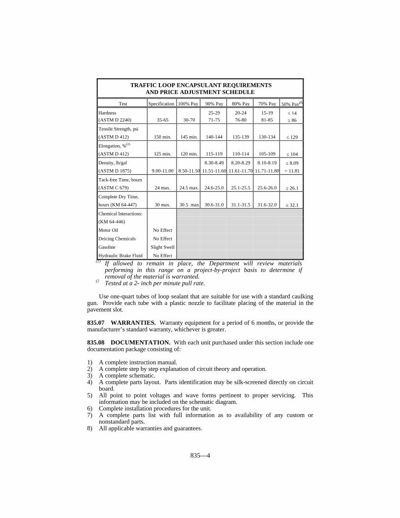
835—4
TRAFFIC LOOP ENCAPSULANT REQUIREMENTSAND PRICE ADJUSTMENT SCHEDULE
Test Specification 100% Pay 90% Pay 80% Pay 70% Pay 50% Pay(1)
Hardness 25-29 20-24 15-19 ≤ 14(ASTM D 2240) 35-65 30-70 71-75 76-80 81-85 ≥ 86
Tensile Strength, psi
(ASTM D 412) 150 min. 145 min. 140-144 135-139 130-134 ≤ 129
Elongation, %(2)
(ASTM D 412) 125 min. 120 min. 115-119 110-114 105-109 ≤ 104
Density, lb/gal 8.30-8.49 8.20-8.29 8.10-8.19 ≤ 8.09
(ASTM D 1875) 9.00-11.00 8.50-11.50 11.51-11.60 11.61-11.70 11.71-11.80 = 11.81
Tack-free Time, hours
(ASTM C 679) 24 max. 24.5 max. 24.6-25.0 25.1-25.5 25.6-26.0 ≥ 26.1
Complete Dry Time,
hours (KM 64-447) 30 max. 30.5 max 30.6-31.0 31.1-31.5 31.6-32.0 ≥ 32.1
Chemical Interactions:
(KM 64-446)
Motor Oil No Effect
Deicing Chemicals No Effect
Gasoline Slight Swell
Hydraulic Brake Fluid No Effect(1) If allowed to remain in place, the Department will review materials
performing in this range on a project-by-project basis to determine ifremoval of the material is warranted.
(2 Tested at a 2- inch per minute pull rate.
Use one-quart tubes of loop sealant that are suitable for use with a standard caulkinggun. Provide each tube with a plastic nozzle to facilitate placing of the material in thepavement slot.
835.07 WARRANTIES. Warranty equipment for a period of 6 months, or provide themanufacturer’s standard warranty, whichever is greater.
835.08 DOCUMENTATION. With each unit purchased under this section include onedocumentation package consisting of:
1) A complete instruction manual.2) A complete step by step explanation of circuit theory and operation.3) A complete schematic.4) A complete parts layout. Parts identification may be silk-screened directly on circuit
board.5) All point to point voltages and wave forms pertinent to proper servicing. This
information may be included on the schematic diagram.6) Complete installation procedures for the unit.7) A complete parts list with full information as to availability of any custom or
nonstandard parts.8) All applicable warranties and guarantees.

836—1
SECTION 836 DURABLE PREFORMED PAVEMENTMARKINGS TYPE I TAPE
836.01 TYPE I TAPE. Use preformed pavement marking material consisting of whiteor yellow films with glass beads incorporated to provide immediate and continuingretroreflection.
Use preformed pavement marking material capable of adhering to new dense andopen graded asphalt surfaces, during the paving operation, or portland cement concrete bya pre-coated pressure sensitive adhesive. The Engineer may require a primer toprecondition the pavement surface. Ensure that the markings conform to pavementcontours by the action of traffic. Ensure that, after application, the markings areimmediately ready for traffic.
Ensure that these markings provide long term reflectivity, as determined in thefollowing performance requirements, when applied according to the manufacturer’sinstructions.
Ensure that the preformed markings are suitable for use one year after the date ofreceipt when stored according to the manufacturer’s recommendations.
A) Composition. Use retroreflective preformed pavement markings consisting of amixture of high quality polymeric materials, pigments, and glass beads distributedthroughout its base cross sectional area.
B) Reflectance. Ensure that the white and yellow markings have the following initialminimum reflectance values as measured according to the testing procedures ofASTM D 4061. Measure the specific luminance (SL), and express it as millicandelasper lux per square meter. Use a test distance of 30 meters and a sample size of a 24by 30-inch rectangle.
C) Skid Resistance. Ensure that the surface of the retroreflective material provides aninitial minimum skid resistance value of 45 BPN when tested according to ASTM E303.
D) Patchability. Ensure that the pavement marking material is capable of use forpatching worn areas of the same type according to the manufacturer’srecommendations.
E) Material Warranty. For a period of 48 months from the date of installation,regardless of ADT and under normal traffic conditions, the manufacturer will providereplacement material for any material used as longitudinal markings that (1) fails toretain the minimum reflectivity values (minimum replacement zone is 300 feet ofroadway length), or (2) fails due to loss of adhesion or complete wear through.
The Department will take measurements according to KM 64-202 or KM64-203. The minimum reflectivity requirements, as measured with a LTL2000retroreflectometer or mobile 30M geometry device, are as follows:
White: 200 mcd/lux/square meterYellow: 150 mcd/lux/square meter
INITIAL REFLECTANCE
Color Entrance Observation SpecificAngle Angle Luminance
White 86.5º 1.0º 700 minimumWhite 86.0º 0.2º 1,100 minimumYellow 86.5º 1.0º 500 minimumYellow 86.0º 0.2º 800 minimum

836—2
F) Testing and Acceptance. Furnish the manufacturer’s typical test analysis for thedurable preformed pavement markings and the manufacturer’s certification statingthat the material conforms to this section.
The Engineer will submit the above documentation, accompanied by a SampleIdentification Form to the District Materials Engineer. The Department will baseacceptance on a review of the test data, a certification statement, and initial fieldevaluation.
837—1
SECTION 837 EXTRUDED THERMOPLASTIC PAVEMENTMARKING MATERIALS
837.01 PRE-MIX BEADS. Supply the thermoplastic material with pre-mix beads. The gradation and coating are at the manufacturer’s discretion. Include the selectedgradation on the product certification so that the Department may analyze the verificationsamples.
837.02 DROP ON BEADS. Use beads that will ensure the pavement marking materialwill meet retroreflectivity requirements. The Department will evaluate the beads as part ofthe marking system through retroreflectivity readings.
837.03 THERMOPLASTIC MATERIAL. Use a maleic-modified glycerol ester resin(alkyd binder) to formulate the thermoplastic material. Use material that, when heated,does not exude fumes that are toxic or injurious to persons or property.
837.03.01 Composition. Ensure that the pigment, beads, and filler are uniformlydispersed in the resin. Use material that is free from all skins, dirt, and foreign objects,and conforms to following table.
(1)Use a binder that consists of a mixture of synthetic resins, at least one beingsolid at room temperature, and high boiling point plasticizers. Ensure that atleast one-third of the binder composition is solid maleic-modified glycerolester resin and is not less than 8 percent by weight of the entire materialformulation. Do not use alkyd binder that contains petroleum basedhydrocarbon resins.
(2)The manufacturer may choose the amount of calcium carbonate and inertfillers, providing all other requirements of this section are met.
837.03.02 Physical Characteristics.
A) Specific Gravity. Do not exceed 2.3.B) Color. For thermoplastic material heated for 4 hours at 425 °F under agitation,
conform to the following luminosity and color requirements:
1) Luminosity. - Daylight reflectance at 45 degrees entrance angle, 0 degreesobservation angle.
White - 75 percent minimum. Yellow - 45 percent minimum. 2) Color - Conform to the CIELAB color coordinates defining yellow and white
as determined with a spectrophotometer using a D65 illuminant with a 45degree entrance angle and 0 degree observation angle geometry.
COMPOSITION(Percentage by Weight)
Component White YellowBinder, (1) 18.0 min. 18.0 min.Glass Beads (Premixed) 30 - 40 30 - 40Titanium Dioxide 10.0 min. —Calcium Carbonate & Inert Fillers (2) 42.0 max. 50.0 max.Lead Chromate 0.0 max. 4.0 min.

837—2
CIELAB COLOR COORDINATESYellow White
L* 80.80 94.92a* 19.04 -2.18b* 88.57 3.10Allowable Variation 2.0 ? E Maximum 2.0 ? E Maximum
C) Set Time. Use material that, when applied at a temperature range of 415 ± 15 ºFand thickness of 40 to 120 mils, sets to bear traffic in not more than 2 minuteswhen the air and road surface temperature is approximately ≥ 50 ± 3 ºF, and notmore than 10 minutes when the air and road surface temperature isapproximately < 50 ± 3 ºF.
D) Bond Strength. After heating the thermoplastic material for 4 hours at 425 ºF,ensure that the bond strength to concrete exceeds 180 psi, according to ASTM D4796.
E) Cracking Resistance at Low Temperature. After heating the thermoplasticmaterial for 4 hours at 425 ºF, applying it to concrete blocks, and cooling it 46 ºF,ensure that the material shows no cracks when observed from a distanceexceeding one foot.
F) Impact Resistance. After heating the thermoplastic material for 4 hours at425 ºF and forming test specimens, ensure that the impact resistance is aminimum of 1.13 joules.
G) Softening Point. After heating the thermoplastic material for 4 hours at 425 ºFand testing according to ASTM D 36, ensure that the materials have a softeningpoint of 215 ± 15 ºF.
H) Flowability. After heating the thermoplastic material for 4 hours at 425 ºF andtesting for flowability, ensure that the white thermoplastic has a maximumresidue of 18 percent and the yellow thermoplastic has a maximum residue of 21percent.
I) Yellowness Index. Use white thermoplastic material that does not exceed ayellowness index of 0.15.
J) Flowability (Extended Heating). After heating and stirring the thermoplasticmaterial for 8.5 hours at 425 °F and testing for flowability, ensure that thethermoplastic has a maximum residue of 28 percent.
K) Flash Point. Use thermoplastic material that has a flash point not less than475 °F when tested according to ASTM D 92.
L) Storage Life. Ensure that the material conforms to this section for a period ofone year. The thermoplastic must also melt uniformly with no evidence of skinsor unmelted particles for this one year period. The manufacturer shall replaceany material not conforming to the above requirements.
837.03.03 Certification, Testing and Approval.
A) Sampling. The manufacturer shall perform tests on a minimum of onecomposite sample per lot of thermoplastic produced. Provide a composite samplecomposed of equal portions of randomly selected samples taken from each10,000 pounds during the lot’s production. Use a lot size of approximately44,000 pounds unless the total order is less than this amount. Ensure that theone quart composite sample is collected by an independent laboratory approvedby the Division of Materials.
B) Testing. The manufacturer shall perform the following tests on the thermoplasticpavement marking material: Color, Reflectance and Yellowness Index, BondStrength (Yellow and White), Low Temperature Stress Resistance, ImpactResistance, Softening Point, Flowability, Flowability (Extended Heating), DryingTime and Specific Gravity.
837—3
C) Submission. Before shipment of the thermoplastic material, the manufacturershall submit to the Division of Materials a 1/2-gallon composite sample of thethermoplastic material, a copy of the manufacturer’s test results, a listing of thetheoretical composition of the thermoplastic material (see Composition table inSubsection 837.03.01) and a signed statement of certification that includes thefollowing information:
1) A statement that the thermoplastic material complies with all requirementsof this section.
2) The quantity of material represented in the lot or batch.3) The destination of the shipment.
D) Verification. The Department reserves the right to verify the manufacturer’s testresults by conducting any or all of the tests listed above. The Division ofMaterials or an approved independent laboratory will perform this testing at theDepartment’s expense and according to AASHTO T 250 and Kentucky StandardTest Methods. Upon completion of testing, the Division of Materials will notifythe supplier of approval and forward copies of the material’s certification andapproval to the Division of Traffic.
837.03.04 Packaging. Package thermoplastic pavement marking material insuitable 50-pound containers to which it shall not adhere during shipment or storage. Include a label stating that the material is to be maintained within a temperature range of400-440 ºF during application. Provide the thermoplastic material in either block orgranular form.
838—1
SECTION 838 FLEXIBLE DELINEATOR POSTS
838.01 GENERAL. Furnish surface and ground mounted flexible delineator posts fromthe Department’s List of Approved Materials. The Department will approve flexibledelineators based upon their NTPEP performance evaluation. The Department considersthe flexible delineator posts to include the post, reflective element, and mountinghardware.
838.02 PACKAGING. Securely fasten posts of the same type and length in bundles of2,000 pounds or less in a manner that is easily handled by a fork lift and that preventsslipping during handling and shipping. The Engineer will reject posts with excessivelydamaged finishes.
839—1
SECTION 839 KY TYPE I GLASS BEADS
839.01 GLASS BEADS. Use for application to reflective pavement markings. Conform to AASHTO M 247, moisture resistant specifications with the followingadditional requirements for gradation and percentage of rounds:
Gradation: Sieve Size Percent PassingNo. 20 98-100No. 30 70-90No. 40 —No. 50 0-20No. 80 0-5
Rounds: 70% minimum for + 50 beads
839.01.01 Sampling. The Department will obtain random samples of all shipmentsthat are intended for use by State Traffic Forces at the point of delivery. The Departmentwill evaluate the beads for acceptance prior to use. The Department will accept beads forContractor use based upon manufacturer certification.
839.01.02 Testing. The Department will test according to AASHTO M 247 and thefollowing.
A) Chemical Resistance Test. Place three, 0.1 to 0.2-ounce, samples of the beadsin separate Pyrex-glass beakers or porcelain dishes. Cover one sample withdistilled water; one with a 3N solution of sulfuric acid; and one with a 50 percentsolution of sodium sulfide. Examine the samples microscopically after one hourof immersion. Reject the beads if they darken or “frost”.
B) Moisture Resistance Test. Place approximately 2 pounds of glass beads in aclean cotton bag not treated with sizing material. Immerse the bag in water,completely covering the beads, for approximately 30 seconds. Remove the bagand wring free of excess water. Hang the bag in room air for 2 hours to dry. Transfer the beads slowly to a clean, dry, standard (4-inch stem, and a 1/4-inchdiameter exit) glass funnel. Accept beads that flow freely through the funnel.
839.01.03 Approval. The Department will notify the vendor of acceptance when alltesting is complete. The Department will evaluate beads used by the Contractor as part ofthe painted line by use of hand-held or mobile retroreflectance readings.

840—1
SECTION 840 RAISED MARKERS
840.01 TYPE IV MARKERS. Provide markers from the Department’s List ofApproved Materials. Type IV markers are replacement lenses for use in Type V markercastings.
840.02 TYPE V MARKERS. Provide markers from the Department’s List of ApprovedMaterials. Type V markers consist of an iron casting with a Type IV marker (mono or bi-directional) attached.
840.03 TYPE IVA MARKERS. Provide markers from the Department’s List ofApproved Materials. Type IVA markers are surface mounted lenses for temporary use inwork zones.
840.04 SAMPLING. Obtain a manufacturer’s certification for each shipment. Includewith each shipment of adhesive a written statement from the manufacturer certifying that itconforms to the recommendations of the marker manufacturer, and stating the minimumtemperature the adhesive can be satisfactorily mixed and applied.
840.05 PACKAGING. Suitably and substantially package all materials with the nameand address of the manufacturer and vendor, contract or purchase number, kind ofmaterial, trade name, and net contents plainly marked on each package.
841—1
SECTION 841 —LATEX ADMIXTURE
841.01 DESCRIPTION. This section covers latex admixtures for concrete bridge deckoverlays.
841.02 REQUIREMENTS. Select a latex admixture from the Department’s List ofApproved Materials. Use a latex admixture that is produced in the United States.
Manufacturers desiring prequalification of new products shall have their producttested and evaluated by a qualified independent laboratory, or the Department’s Divisionof Materials, according to the Prequalification Test Program in the U.S. Department ofTransportation Research Report No. FHWA-RD-78-35. When analysis is performed byan independent laboratory, the manufacturer shall submit the certified test results alongwith a 5-gallon sample of the latex admixture to the Department’s Division of Materials. The Department will approve the latex admixture based upon the submitted informationand evaluation of the sample.
Use only latex admixtures that are free of chlorides.Include with each shipment of latex admixture a report of tests performed according to
the Certification Program in Report No. FHWA-RD-78-35. In addition to actual testresults, include in the report the date of manufacture, batch or lot number(s), quantityrepresented, manufacturer’s name, place of manufacture, a statement that all test resultsare satisfactory, the date the one-year certification period will expire, and signature ofmanufacturer’s representative.
The Department will check sample and test each lot of latex and will remove it fromthe list of approved materials at any time there is an indication of nonconformity orquestionable quality.
Package and store the latex admixture in containers and storage facilities that protectthe material from freezing and from temperatures above 85 °F. When storing outside ofbuildings during moderate temperatures, keep the material shaded and away from directsunlight. Do not use any latex admixture exposed to freezing temperatures withoutapproval from the Division of Materials.

842—1
SECTION 842 PAVEMENT STRIPING PAINT
842.01 DESCRIPTION. This section covers quick-drying pavement striping paint forpermanent applications.
842.02 APPROVAL. Select materials that conform to the composition requirementsbelow. Submit initial samples for approval before beginning striping operations. Theinitial sample may be sent from the manufacturer of the paint. The Department willrandomly sample and evaluate the paint each week that the striping operations are inprogress.
PAINT COMPOSITIONProperty and Test Method Yellow White
Color (CIELAB)Spectrophotometer using aD65 illuminant at 45°illumination and 0° viewingwith a 2° observer
L* 80.80a* 19.04b* 88.57
With a maximum variationof 2.0 ∆Ecmc
L* 94.92a* -2.18b* 3.10
With a maximum variationof 2.0 ∆Ecmc
LeadASTM D 3335
< 5ppm <5ppm
TiO2
ASTM D 4764NA 10% by wt. of pigment min.
VOCASTM D 2369 and D 4017
1.25-lb/gal max. 1.25-lb/gal max.
Contrast Ratio(at 15 mils wft.)
0.97 0.99
842.03 ACCEPTANCE PROCEDURES FOR NON-SPECIFICATIONPAVEMENT STRIPING PAINT. When non-specification paint is inadvertentlyincorporated into the work the Department will accept the material with a reduction in pay. The percentage deduction is cumulative based on its compositional properties, but will notexceed 60 percent. The Department will calculate the payment reduction on the unit bidprice for the routes where the non-specification paint was used.
PAVEMENT STRIPING PAINT REDUCTION SCHEDULE
Non-conforming Property Color Lead TiO2 VOC ContrastReduction Rate 10% 60% 10% 60% 10%

843—1
SECTION 843 GEOTEXTILE FABRICS
843.01 DESCRIPTION. This section covers requirements for geotextile fabrics forslope protection and channel lining, underdrains, subgrade or embankment foundationstabilization, and drainage blankets.
843.01.01 Geotextile Fabric. Use either woven or non-woven fabric consisting onlyof long chain polymeric filaments or yarns such as polypropylene, polyethylene, polyester,polyamide, or polyvinylidene-chloride formed into a stable network such that the filamentsor yarns retain their relative position to each other. Use fabric that is inert to commonlyencountered chemicals and free of defects or flaws significantly affecting its physical orfiltering properties. Use circular-knit geotextile conforming to ASTM D 6707 forperforated pipe socks.
Ensure that the fabric, except wrapping placed directly against perforated pipe, isformed in widths of at least 6 feet. When necessary, sew sheets of fabric together to formrequired fabric widths. Sew the sheets of fabric together at the point of manufacture orother approved locations.
The geotextile manufacturer is responsible for establishing and maintaining a qualitycontrol program to ensure compliance with this section. The manufacturer mustparticipate in the National Transportation Product Evaluation Program (NTEP) forGeotextiles and Geosynthetics.
A) Packaging. During all periods of shipment and storage, wrap the fabric in aheavy duty protective covering to protect the fabric from direct sunlight,ultraviolet rays, temperatures greater than 140 °F, mud, dirt, dust, and debris.
B) Physical Requirements. Conform to the following applicable table as specifiedfor each use.
C) Acceptance. Obtain the Department’s approval for all material beforeincorporating it into the project.
TYPE I FABRICGEOTEXTILES FOR SLOPE PROTECTION AND CHANNEL
LININGProperty Minimum Value(1) Test Method
Grab Strength (lbs) 200 ASTM D 4632Elongation (%) 15 ASTM D 4632Sewn Seam Strength(2) (lbs) 180 ASTM D 4632Puncture Strength (lbs) 80 ASTM D 4833Trapezoid Tear (lbs) 50 ASTM D 4533Apparent Opening SizeU.S. Std. Sieve
Sieve U.S. #40 ASTM D 4751
Permeability (cm/s) 0.004 ASTM D 4491Ultraviolet Degradationat 500 hours
70% strengthretained for all classes
ASTM D 4355
Flow Rate(gal./min./ft2)
20 ASTM D 4491
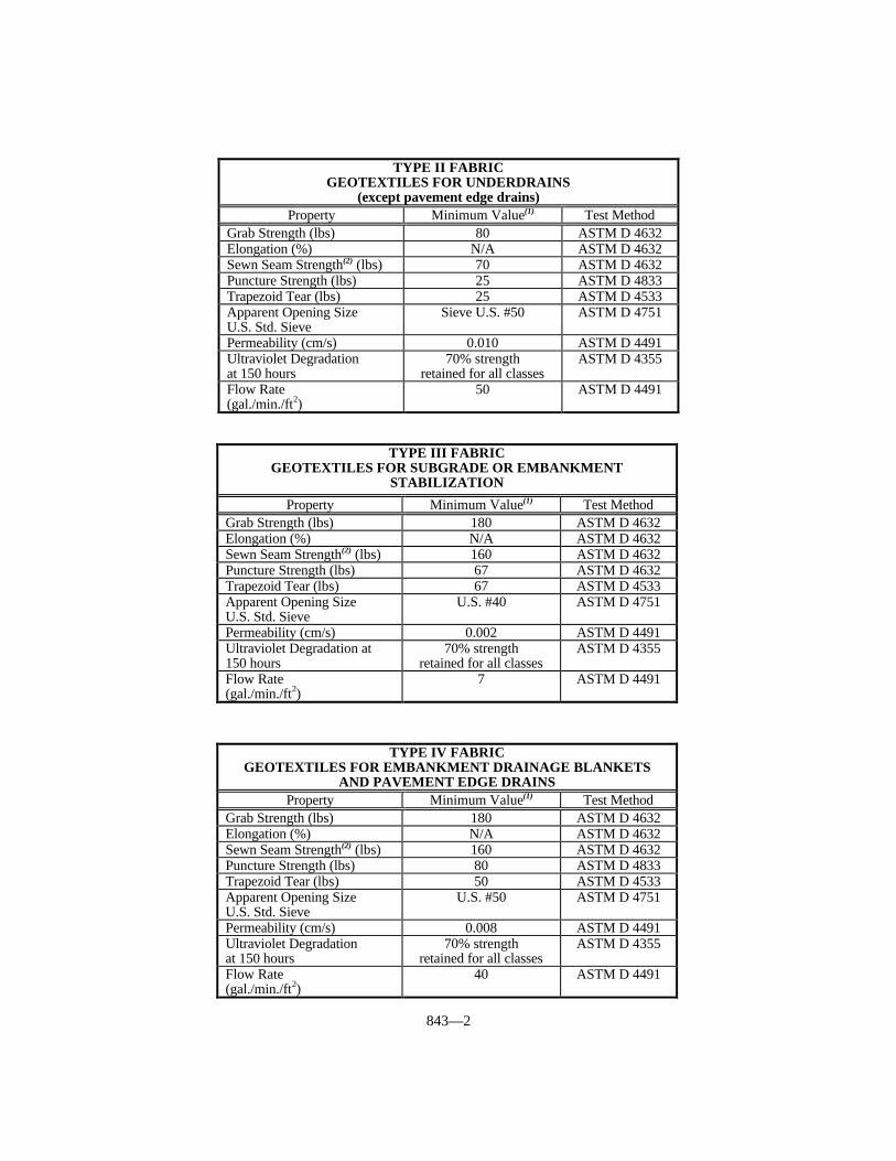
843—2
TYPE II FABRICGEOTEXTILES FOR UNDERDRAINS
(except pavement edge drains)Property Minimum Value(1) Test Method
Grab Strength (lbs) 80 ASTM D 4632Elongation (%) N/A ASTM D 4632Sewn Seam Strength(2) (lbs) 70 ASTM D 4632Puncture Strength (lbs) 25 ASTM D 4833Trapezoid Tear (lbs) 25 ASTM D 4533Apparent Opening SizeU.S. Std. Sieve
Sieve U.S. #50 ASTM D 4751
Permeability (cm/s) 0.010 ASTM D 4491Ultraviolet Degradationat 150 hours
70% strengthretained for all classes
ASTM D 4355
Flow Rate(gal./min./ft2)
50 ASTM D 4491
TYPE III FABRICGEOTEXTILES FOR SUBGRADE OR EMBANKMENT
STABILIZATION
Property Minimum Value(1) Test MethodGrab Strength (lbs) 180 ASTM D 4632Elongation (%) N/A ASTM D 4632Sewn Seam Strength(2) (lbs) 160 ASTM D 4632Puncture Strength (lbs) 67 ASTM D 4632Trapezoid Tear (lbs) 67 ASTM D 4533Apparent Opening SizeU.S. Std. Sieve
U.S. #40 ASTM D 4751
Permeability (cm/s) 0.002 ASTM D 4491Ultraviolet Degradation at150 hours
70% strengthretained for all classes
ASTM D 4355
Flow Rate(gal./min./ft2)
7 ASTM D 4491
TYPE IV FABRICGEOTEXTILES FOR EMBANKMENT DRAINAGE BLANKETS
AND PAVEMENT EDGE DRAINSProperty Minimum Value(1) Test Method
Grab Strength (lbs) 180 ASTM D 4632Elongation (%) N/A ASTM D 4632Sewn Seam Strength(2) (lbs) 160 ASTM D 4632Puncture Strength (lbs) 80 ASTM D 4833Trapezoid Tear (lbs) 50 ASTM D 4533Apparent Opening SizeU.S. Std. Sieve
U.S. #50 ASTM D 4751
Permeability (cm/s) 0.008 ASTM D 4491Ultraviolet Degradationat 150 hours
70% strengthretained for all classes
ASTM D 4355
Flow Rate(gal./min./ft2)
40 ASTM D 4491

843—3
(1) Minimum. Use value in weaker principal direction. All numerical valuesrepresent minimum average roll value (i.e., test results from any sampled rollin a lot shall meet or exceed the minimum values in the table).
(2) Values apply to both field and manufactured seams.
843.01.02 Acceptance Procedures for Non-Specification Fabric. Ensure that allgeotextile fabric conforms to the requirements of this section. However, when non-specification geotextile fabric is inadvertently incorporated into the work before completionof testing, the Department may accept the material with a reduction in pay, provided thefailure is marginal and will not cause poor performance. When the failure is excessive,then remove the geotextile fabric, and replace it unless the Engineer determines that thegeotextile fabric can remain in place. The Department will apply the largest paymentreduction when the material fails to meet more than one specification requirement. TheDepartment will calculate the payment reduction on the invoice cost of the materialdelivered at the project site. The Department will reject geotextile fabric that fails and hasnot been incorporated into the work.
AOS PAYMENT REDUCTION#35 - #40 or #45 - #50 0-5 6-10 11-15 16-20 21 or moreGlass Beads PassingFabric as ApplicableReduction Rate 0% 20% 30% 40% *
GRAB STRENGTH PAYMENT REDUCTION
% of Requirement 100% or more 90-99% 75-89% 74% or LessReduction Rate 0% 25% 40% *
ELONGATION PAYMENT REDUCTION(TYPE I FABRIC ONLY)
% of Requirement 100% or more 90-99% 75-89% 74% or LessReduction Rate 0% 25% 40% *
SEWN SEAM STRENGTH PAYMENT REDUCTION
% of Requirement 100% or more 90-99% 75-89% 74% or LessReduction Rate 0% 25% 40% *
FLOW RATE PAYMENT REDUCTION% of Requirement 100% or more 90-99% 75-89% 74% or LessReduction Rate 0% 25% 40% *
*Remove and replace the fabric unless the Engineer determines the fabric canremain in place at a 100% reduction rate.
843.01.03 Fastener Pins. The Engineer will accept fastener pins based on visualinspection on the project. Conform to the following:
A) Underdrain Systems. Use pins that are formed of No. 9 diameter or heaviersteel wire and are at least one foot long with a 4-inch right angle bend on oneend.

843—4
B) Slope Protection, Channel Lining, Subgrade and Embankment FoundationStabilization, and Wrapped Aggregate Drainage Blankets. Provide fastenerpins that are formed of 3/16 inch diameter or heavier steel, pointed at one end,with a head on the opposite end to retain a washer with a minimum diameter of1 1/2 inches.

844—1
SECTION 844 MINERAL ADMIXTURES FOR CONCRETE
844.01 FLY ASH REQUIREMENTS. For fly ash added to concrete mixtures as aseparate ingredient, conform to ASTM C 618, Class F or Class C, except ensure that theloss on ignition does not exceed 3.0 percent.
Concrete containing Class C fly ash may reduce sulfate resistance. Susceptibility tosulfate attack relates to the resistance factor, R. The value of R is defined as the ratio,(CaO -5.0)/(Fe2O3), as determined from the fly ash oxide analysis. A resistance factor (R)greater than 3.0 indicates a reduction in sulfate resistance. Do not use Class C fly ashhaving an R ratio greater than 3.0 in concrete where sulfate attack is possible. Identify thelocations on the project where concrete containing Class C fly ash is to be used, and obtainthe Engineer’s approval of its use before beginning concrete work.
844.02 APPROVAL.
844.02.01 Fly Ash. Select from the Department’s List of Approved Materials for flyash sources. To be placed on the list, furnish samples and ASTM C 618 test datadeveloped over the previous 3 months, and conform to the following requirements:
1) Ensure that the fly ash supplier has a quality control program satisfactory to theEngineer, to ensure the fly ash delivered to the project has uniform propertiesconforming to this section. To be acceptable, laboratories performing tests on flyash for conformance to ASTM C 618 shall participate in the laboratoryevaluation and sample proficiency program conducted by the Cement andConcrete Reference Laboratory of ASTM. This requirement does not apply toroutine process control testing at the plant site for fineness, loss on ignition, anduniformity. A Department certified technician shall perform testing at the plant.
2) Provide with each shipment of fly ash a certification from the supplier that the flyash complies with this section and ASTM C 618.
3) Provide with each shipment actual results of tests for fineness and loss onignition, and uniformity when applicable. The concrete producer shall keep thesetest results on file and available for review by the Engineer for a period of at least3 years after receipt of the fly ash.
4) The Department reserves the right to perform any sampling and testing on TypeIP cement or fly ash when deemed necessary or desirable.
844.02.02 Ground Granulated Blast Furnace (GGBF) Slag. The Department’sDivision of Materials maintains a list of approved GGBF Slag sources by producer.Furnish samples and ASTM C 989 test data for the previous six months and meet thefollowing requirements to obtain approval.
1) Submit the GGBF slag supplier’s quality control program to the Engineer forapproval. The GGBF slag delivered to the project shall have uniform propertiescomplying with this specification. Laboratories performing tests on GGBF slagfor conformance to ASTM C 989 shall participate in the laboratory evaluationprogram conducted by the Cement and Concrete Reference Laboratory of ASTM.
2) Submit certification with each shipment of GGBF slag to document itscompliance with this specification and ASTM C 989.
3) Submit actual ASTM C 989 test results for fineness, air content, slag activityindex, sulfide sulfur content, and sulfate ion content with each shipment.
The Department reserves the right to perform all sampling and testing on GGBF slagthat it deems necessary or desirable.
844.02.03 Microsilica. The Department’s Division of Materials maintains a list ofapproved microsilica admixtures by brand name and manufacturer. Furnish samples and

844—2
AASHTO M 307 test data for the previous six months and meet the followingrequirements to obtain approval:
1) Submit the microsilica supplier’s quality control program to the Engineer forapproval. The microsilica delivered to the project shall have uniform propertiescomplying with this specification. Laboratories performing tests on microsilicafor conformance to AASHTO M 307 shall participate in the laboratory evaluationprogram conducted by the Cement and Concrete Reference Laboratory of ASTM.
2) Submit certification with each shipment of microsilica to document itscompliance with this specification and AASHTO 307.
3) Submit actual AASHTO M 307 tests results for the chemical and physicalrequirements with each shipment.
844.03 NON-SPECIFICATION FLY ASH. When either Class C or Class F sampledfly ash fails to meet specification requirements for loss on ignition (LOI), but the Engineerdetermines that concrete produced using the fly ash meets requirements for entrained airand compressive strength, the Engineer will reduce the price by 5.0 percent of theContractor’s invoice cost of the fly ash for each 0.1 percent that the fly ash LOI is above3.0 percent. This procedure is intended to provide for acceptance at a reduced Contractprice when material is discovered to not meet specification requirements after work isperformed, and is not intended as a means to utilize non-specification material.
The Engineer will accept fly ash on the basis of certification and being from anapproved source and project samples passing the applicable requirements of ASTM C 618and/or ASTM C 593. Some variability or small departures from the requirements do notadversely affect properties of the finished product enough for removal and replacement. Therefore, the Department will use the following pay tables when deviations occur. Whena sample fails more than one test, the Department will impose the largest reduction rate. The Department will calculate the payment reduction on the invoice cost of the fly ashdelivered to the concrete plant or to the project site.
STRENGTH ACTIVITY INDEX PAYMENT REDUCTIONControl with Cement (%) 75 or more 70-74 65-69 64 or lessPSI with Lime (Class F) 800 or more 775-799 750-774 749 or lessReduction Rate 0% 25% 50% *
FINENESS PAYMENT REDUCTION% Retained on No. 325 Sieve 0-34 35-40 41-45 46 or moreReduction Rate 0% 25% 50% *
AUTOCLAVE EXPANSION PAYMENT REDUCTIONExpansion ± (%) 0.8 0.9 1.0 1.1 or moreReduction Rate 0% 25% 50% *
WATER REQUIREMENT PAYMENT REDUCTIONControl (%) 105 or less 106-110 111-115 116 or moreReduction Rate 0% 25% 50% *

844—3
*Remove and replace finished product unless the Engineer determines that it canremain in place at a 100% reduction rate.
CHEMICAL REQUIREMENTS PAYMENT REDUCTIONSiO2+Al2O3+Fe2O3 (%) (Class F) 70 or more 65-79 60-64 59 or lessSiO2+Al2O3+Fe2O3 (%) (Class C) 50 or more 45-49 40-44 39 or lessSO3 (%) 0-5 6 7 8 or moreMoisture Content (%) 0-3 4 5 6 or moreAvailable Alkalies as (Na2O) (%) 0-1.5 1.6 1.7 1.8 or moreReduction Rate 0% 25% 50% *

845—1
SECTION 845 FABRIC WRAPPED BACKFILL DRAINMATERIALS
845.01 DESCRIPTION. Place fabric wrapped backfill drains at locations where depthto weep hole flowline is 30 feet or less.
845.02 FABRIC WRAPPED BACKFILL DRAIN. Select from the Departments Listof Approved Materials. Provide Class I fabric wrapped backfill drains when the depth toweep hole flowline is 12 feet or less. Provide Class II fabric wrapped backfill drains whenthe depth to weep hole flow line is between 12 feet and 30 feet.
845.02.01 Compressive Strength. Ensure the drain is capable of withstanding thefollowing compressive load on the wide side, with a maximum deflection of 50 percent:
Class I - 2,000 pounds per square foot.Class II - 5,000 pounds per square foot.
845.02.02 Core. Use a rectangular core at least 17 inches wide, with nominalthickness of at least 0.7 inch, consisting of molded plastic; or of a 3-dimensional structureof mono-filaments bonded at their intersections; or of 3/8-inch average diameter expandedpolystyrene beads bound together with an adhesive compound, sufficiently open to allowfree movement of water entering through the geotextile fabric, and manufacturedspecifically for drainage applications.
845.02.03 Wrapping. Wrap the core on all 4 sides with Type II geotextile fabricconforming to the requirements of Section 843, Type II.
845.03 PACKAGING AND CARE. Wrap the drain in a protective covering to protectthe fabric from direct sunlight, ultraviolet rays, temperatures greater than 140 °F, mud,dirt, dust, and debris during all periods of shipment and storage.
Completely cover with backfill material within 14 calendar days after placement. Ifcompletely backfilling the drain is not feasible, cover exposed portions with approvedmaterial to protect the fabric from direct sunlight. Remove and replace any drain notbackfilled or suitably covered within 14 days after placing at no expense to theDepartment.
845.04 ACCEPTANCE. Furnish the manufacturer’s certification to the Engineerstating the fabric wrapped backfill drains meets all requirements herein. The Engineerwill accept the fabric wrapped backfill drains by certification and visual inspection.


APPENDIX A
TABULATION OFCONSTRUCTION
TOLERANCES

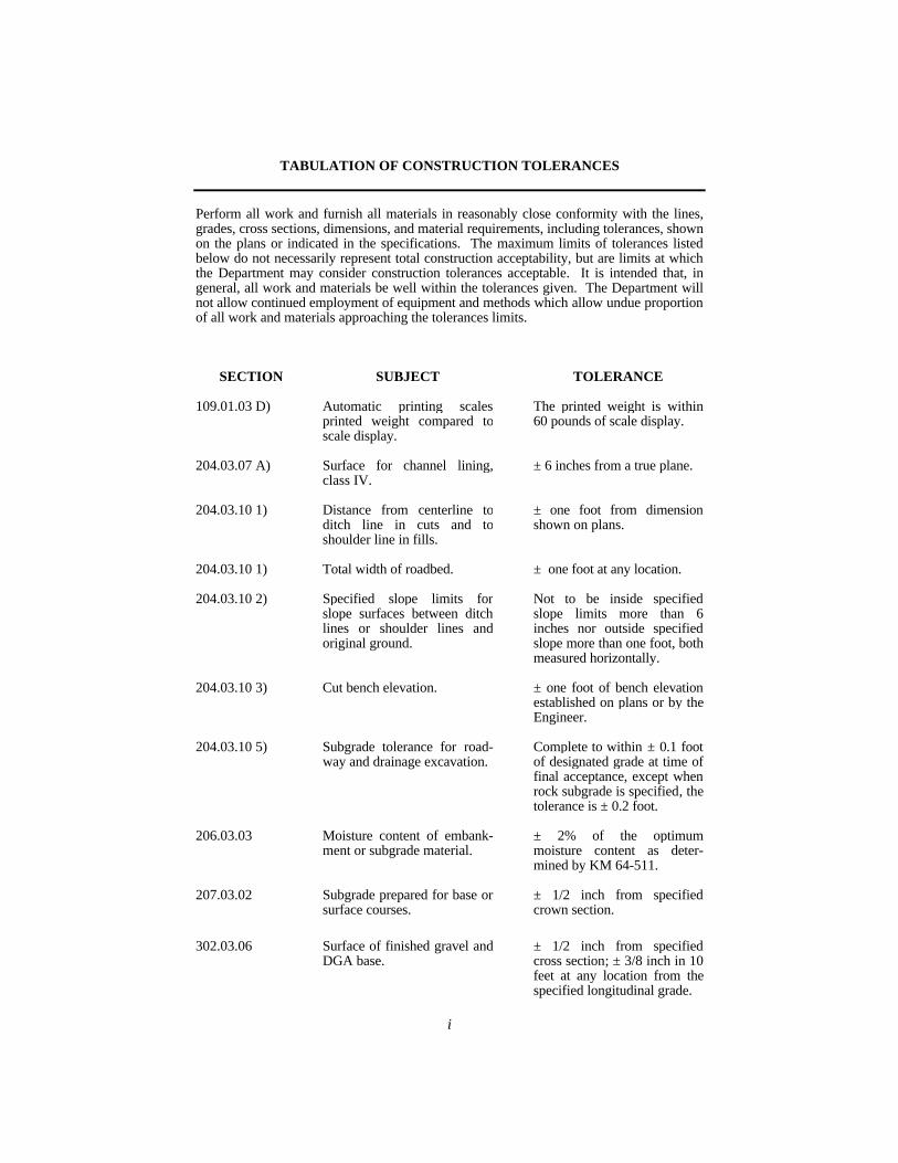
i
TABULATION OF CONSTRUCTION TOLERANCES
Perform all work and furnish all materials in reasonably close conformity with the lines,grades, cross sections, dimensions, and material requirements, including tolerances, shownon the plans or indicated in the specifications. The maximum limits of tolerances listedbelow do not necessarily represent total construction acceptability, but are limits at whichthe Department may consider construction tolerances acceptable. It is intended that, ingeneral, all work and materials be well within the tolerances given. The Department willnot allow continued employment of equipment and methods which allow undue proportionof all work and materials approaching the tolerances limits.
SECTION SUBJECT TOLERANCE
109.01.03 D) Automatic printing scalesprinted weight compared toscale display.
The printed weight is within60 pounds of scale display.
204.03.07 A) Surface for channel lining,class IV.
± 6 inches from a true plane.
204.03.10 1) Distance from centerline toditch line in cuts and toshoulder line in fills.
± one foot from dimensionshown on plans.
204.03.10 1) Total width of roadbed. ± one foot at any location.
204.03.10 2) Specified slope limits forslope surfaces between ditchlines or shoulder lines andoriginal ground.
Not to be inside specifiedslope limits more than 6inches nor outside specifiedslope more than one foot, bothmeasured horizontally.
204.03.10 3) Cut bench elevation. ± one foot of bench elevationestablished on plans or by theEngineer.
204.03.10 5) Subgrade tolerance for road-way and drainage excavation.
Complete to within ± 0.1 footof designated grade at time offinal acceptance, except whenrock subgrade is specified, thetolerance is ± 0.2 foot.
206.03.03 Moisture content of embank-ment or subgrade material.
± 2% of the optimummoisture content as deter-mined by KM 64-511.
207.03.02 Subgrade prepared for base orsurface courses.
± 1/2 inch from specifiedcrown section.
302.03.06 Surface of finished gravel andDGA base.
± 1/2 inch from specifiedcross section; ± 3/8 inch in 10feet at any location from thespecified longitudinal grade.

ii
401.02.01 H) Asphalt Binder control unitmetering devices.
± 1% when tested foraccuracy.
401.02.02 B) Scales for weigh box orhopper or for weightingasphalt material.
Tolerance on over registrationand under registration of notexceeding 0.5% of indicatedweight when tested foraccuracy. The change in loadrequired to noticeably alter theposition of rest of theindicating element(s) of anon-automatic indicatingscale shall not be greater than0.1% of the nominal scalecapacity.
401.02.03 Batch tolerances for automaticbatching or pro-portioninghot-mix asphalt plants.Material:Batch aggregate componentMineral fillerAsphalt BinderZero return (aggregate)Zero return (asphalt materials)Accumulated weight ofbatches.
± 1.5% of total batch weights.± 0.5% of total batch weights.± 0.1% of total batch weights.± 0.5% of total batch weights.± 0.1% of total batch weights.± 2.0% of that total batchweight.
401.03.01 Bituminous plant mixedpavements - JMF tolerances.
See specifications for indivi-dual mixtures.
403.03.06 A) Asphalt base, initial treatmentand resurfacing projects.
The rate of application shallnot exceed designated rate bymore than + 5%.
403.03.06 B) Asphalt base, new construct-ion payment on basis of:weight, or
area.
Total combined thickness ofall layers within ± 1/2 inch ofcompacted plan thickness.
Deficient in thickness by morethan 1/2 inch of compactedplan thickness.
403.03.07 Transverse joints in allasphalt courses.
Deviations do not exceedtolerances described inSubsection 403.03.11 from a10-foot straight edge afterjoint is complete and rolled.
403.03.11 Surfaces of finished courses;asphalt plant-mixed pave-ments.
Finished surfaces of basecourse and binder course shallnot deviate more than ± 1/4inch from 10-foot straightedge.
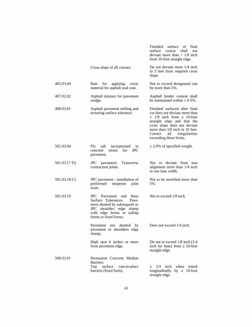
iii
Cross slope of all courses.
Finished surface of finalsurface course shall notdeviate more than + 1/8 inchfrom 10-foot straight edge.
Do not deviate more 1/4 inchin 5 feet from required crossslope.
405.03.04 Rate for applying covermaterial for asphalt seal coat.
Not to exceed designated rateby more than 5%.
407.02.02 Asphalt mixture for pavementwedge.
Asphalt binder content shallbe maintained within ± 0.5%.
408.03.01 Asphalt pavement milling andtexturing surface tolerance.
Finished surfaced after finalcut does not deviate more than± 1/8 inch from a 10-footstraight edge and that thecross slope does not deviatemore than 3/8 inch in 10 feet.Correct all irregularitiesexceeding these limits.
501.03.04 Fly ash incorporated inconcrete mixes for JPCpavement.
± 2.0% of specified weight.
501.03.17 D) JPC pavement; Transversecontraction joints.
Not to deviate from truealignment more than 1/4 inchin one lane width.
501.03.18 C) JPC pavement - installation ofpreformed neoprene jointseals.
Not to be stretched more than5%.
501.03.19 JPC Pavement and BaseSurface Tolerances. Pave-ment abutted by subsequent orJPC shoulder; edge slumpwith edge forms or tailingforms or fixed forms;
Pavement not abutted bypavement or shoulders edgeslump;
High spot 6 inches or morefrom pavement edge.
Not to exceed 1/8 inch.
Does not exceed 1/4 inch.
Do not to exceed 1/8 inch (1/4inch for base) from a 10-footstraight edge.
508.03.01 Permanent Concrete MedianBarriers.Top surface cast-in-placebarriers (fixed form).
± 1/4 inch when testedlongitudinally by a 10-footstraight edge.

iv
508.03.02 Top surface cast-in-placebarriers (slip form).
No deviation more than 1/2inch from the line establishedby the reference wire betweenany 2 reference wire supports.
511.03.01 Masonry drill bits for drillingholes of installation of steeldowels into existing concreteby use of grout.
Diameter no less than 1/8inch greater nor more than 1/2inch greater than diameter ofdowels.
601.02.14 Scales for weighing water,aggregates, cement, and flyash for concrete for structures.
Within + 0.5% of net load onscales.
601.03.03 Concrete for structures air-entraining admixture net aircontent (by volume).
Volume of 6% ± 2% byvolume.
601.03.03 Concrete for structures; accur-acy of individual ingredientmaterials for each batch.
± 2.0% for aggregates.± 1.0% for water & cement.
601.03.03 B) Air content of mortar or grout. Volume of 8% ± 2.0%.
601.03.03 C) 2) Fly ash in concrete mixes forstructures.
± 1.0 % of specified weight.
601.03.03 E) 1) Measuring cement. When the weight of entireshipment of cement in bagsvaries more than 2% from 94pounds per bag. Weigh thecement in bulk on scales.
601.03.03 E) 3) Water metering systems formixing concrete for structures.
+ 1.0% of required amount ofwater per batch.
601.03.08 C) 1) Truck mixing of concrete forstructures, quantity of mixingwater.
Measure and Control to ±1.0%.
601.03.09 A) Variation of finished surfaceof bridge seats.
Not to vary more than 1/32inch above or below true levelplane.
601.03.18 All exposed finished concretesurfaces unless specified else-where in the contract.
Not to vary more than 1/4inch in 10-feet as measuredfrom a straightedge.
602.03.04 All steel reinforcement exceptthat placed in bridge decks.
± 1/2 inch of position, andspecified spacing. ± 1/4 inchof specified clearance fromface of concrete.
602.03.05 Epoxy Coated Tie Wires,Chairs, etc.
Film thickness of epoxycoating.
± 7 mils.
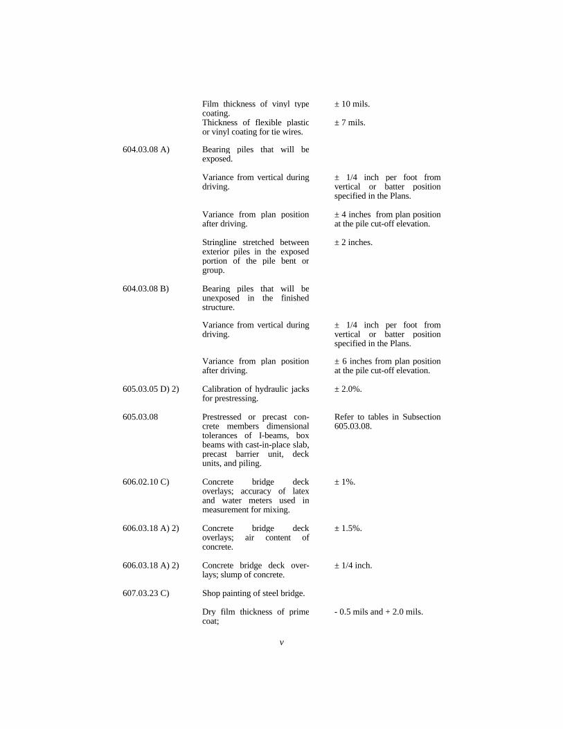
v
Film thickness of vinyl typecoating.Thickness of flexible plasticor vinyl coating for tie wires.
± 10 mils.
± 7 mils.
604.03.08 A) Bearing piles that will beexposed.
Variance from vertical duringdriving.
Variance from plan positionafter driving.
Stringline stretched betweenexterior piles in the exposedportion of the pile bent orgroup.
± 1/4 inch per foot fromvertical or batter positionspecified in the Plans.
± 4 inches from plan positionat the pile cut-off elevation.
± 2 inches.
604.03.08 B) Bearing piles that will beunexposed in the finishedstructure.
Variance from vertical duringdriving.
Variance from plan positionafter driving.
± 1/4 inch per foot fromvertical or batter positionspecified in the Plans.
± 6 inches from plan positionat the pile cut-off elevation.
605.03.05 D) 2) Calibration of hydraulic jacksfor prestressing.
± 2.0%.
605.03.08 Prestressed or precast con-crete members dimensionaltolerances of I-beams, boxbeams with cast-in-place slab,precast barrier unit, deckunits, and piling.
Refer to tables in Subsection605.03.08.
606.02.10 C) Concrete bridge deckoverlays; accuracy of latexand water meters used inmeasurement for mixing.
± 1%.
606.03.18 A) 2) Concrete bridge deckoverlays; air content ofconcrete.
± 1.5%.
606.03.18 A) 2) Concrete bridge deck over-lays; slump of concrete.
± 1/4 inch.
607.03.23 C) Shop painting of steel bridge.
Dry film thickness of primecoat;
- 0.5 mils and + 2.0 mils.
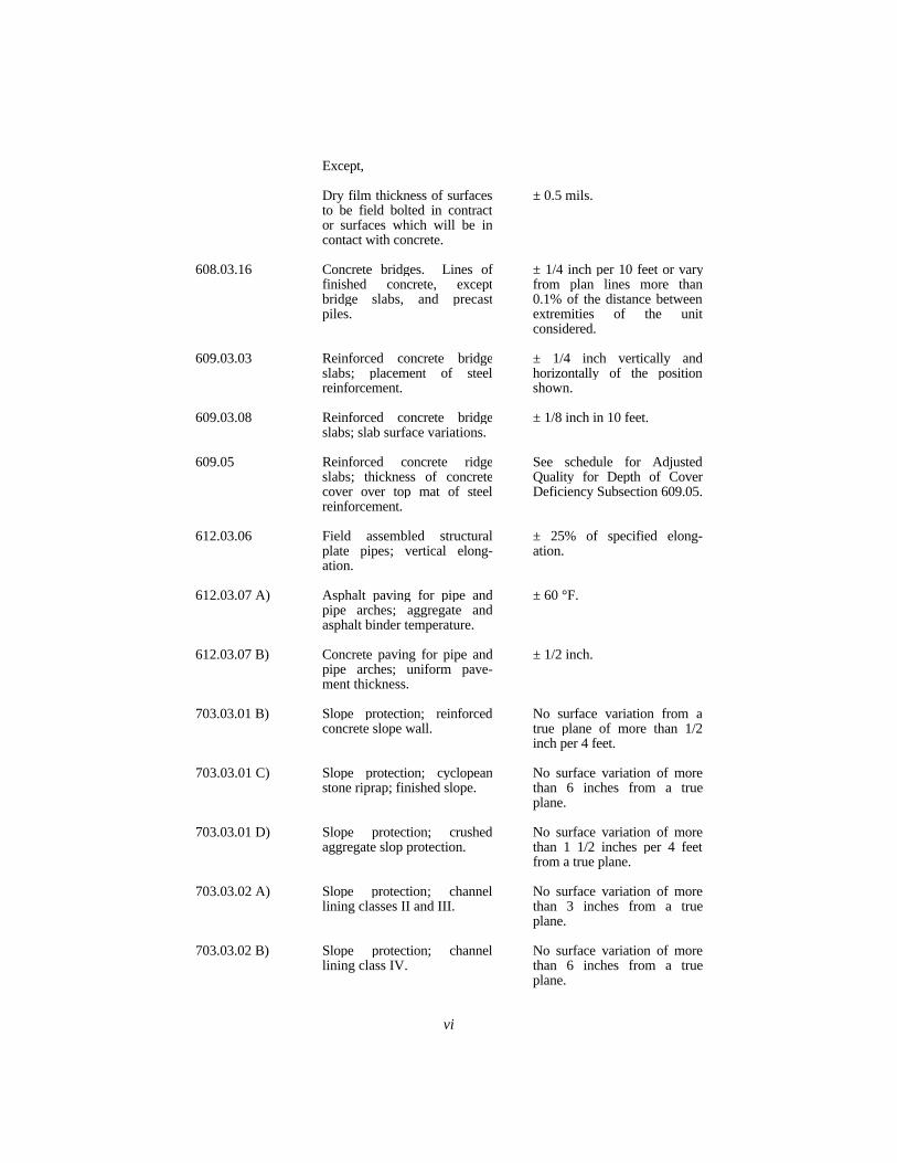
vi
Except,
Dry film thickness of surfacesto be field bolted in contractor surfaces which will be incontact with concrete.
± 0.5 mils.
608.03.16 Concrete bridges. Lines offinished concrete, exceptbridge slabs, and precastpiles.
± 1/4 inch per 10 feet or varyfrom plan lines more than0.1% of the distance betweenextremities of the unitconsidered.
609.03.03 Reinforced concrete bridgeslabs; placement of steelreinforcement.
± 1/4 inch vertically andhorizontally of the positionshown.
609.03.08 Reinforced concrete bridgeslabs; slab surface variations.
± 1/8 inch in 10 feet.
609.05 Reinforced concrete ridgeslabs; thickness of concretecover over top mat of steelreinforcement.
See schedule for AdjustedQuality for Depth of CoverDeficiency Subsection 609.05.
612.03.06 Field assembled structuralplate pipes; vertical elong-ation.
± 25% of specified elong-ation.
612.03.07 A) Asphalt paving for pipe andpipe arches; aggregate andasphalt binder temperature.
± 60 °F.
612.03.07 B) Concrete paving for pipe andpipe arches; uniform pave-ment thickness.
± 1/2 inch.
703.03.01 B) Slope protection; reinforcedconcrete slope wall.
No surface variation from atrue plane of more than 1/2inch per 4 feet.
703.03.01 C) Slope protection; cyclopeanstone riprap; finished slope.
No surface variation of morethan 6 inches from a trueplane.
703.03.01 D) Slope protection; crushedaggregate slop protection.
No surface variation of morethan 1 1/2 inches per 4 feetfrom a true plane.
703.03.02 A) Slope protection; channellining classes II and III.
No surface variation of morethan 3 inches from a trueplane.
703.03.02 B) Slope protection; channellining class IV.
No surface variation of morethan 6 inches from a trueplane.

vii
705.03 Cored hole drainageconnector; diameter of holeshall be equal to the outsidediameter of pipe.
+ 1/2 inch.


APPENDIX B
INDEX

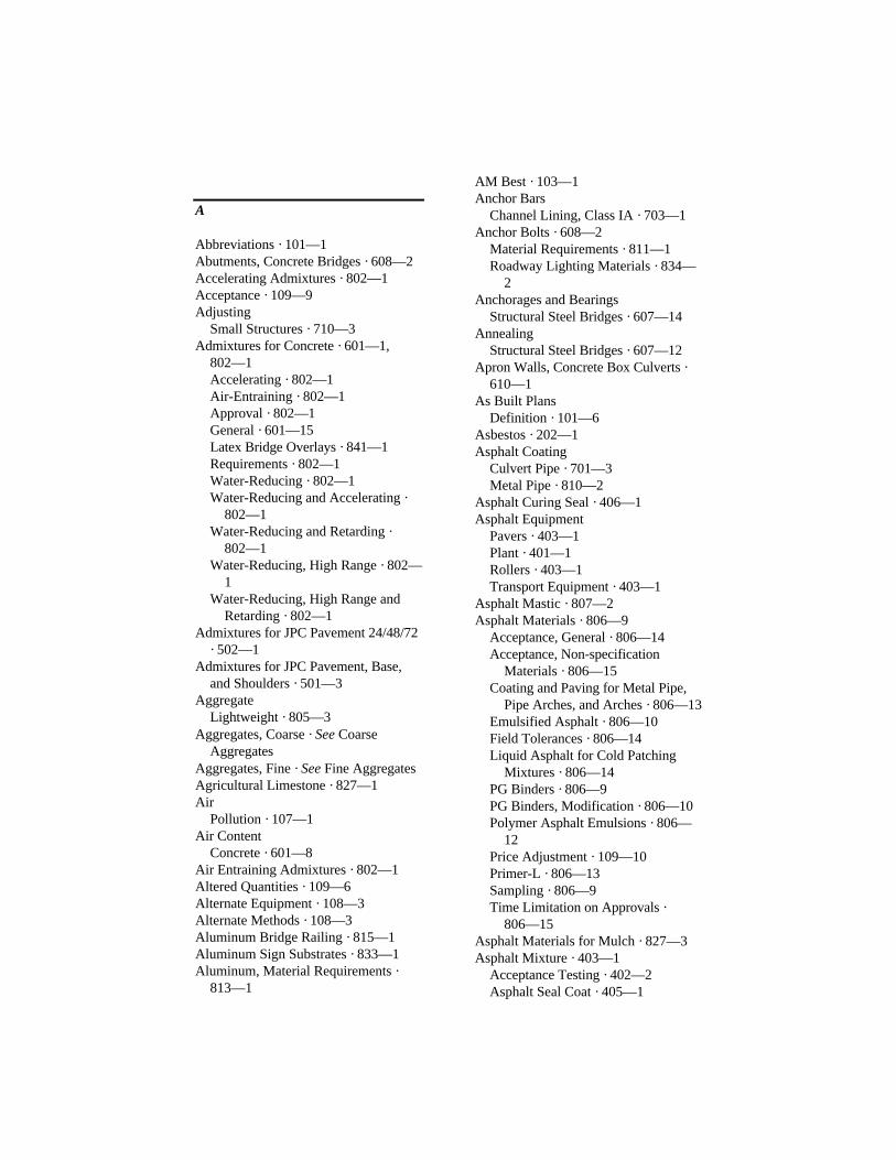
A
Abbreviations · 101—1Abutments, Concrete Bridges · 608—2Accelerating Admixtures · 802—1Acceptance · 109—9Adjusting
Small Structures · 710—3Admixtures for Concrete · 601—1,
802—1Accelerating · 802—1Air-Entraining · 802—1Approval · 802—1General · 601—15Latex Bridge Overlays · 841—1Requirements · 802—1Water-Reducing · 802—1Water-Reducing and Accelerating ·
802—1Water-Reducing and Retarding ·
802—1Water-Reducing, High Range · 802—
1Water-Reducing, High Range and
Retarding · 802—1Admixtures for JPC Pavement 24/48/72
· 502—1Admixtures for JPC Pavement, Base,
and Shoulders · 501—3Aggregate
Lightweight · 805—3Aggregates, Coarse · See Coarse
AggregatesAggregates, Fine · See Fine AggregatesAgricultural Limestone · 827—1Air
Pollution · 107—1Air Content
Concrete · 601—8Air Entraining Admixtures · 802—1Altered Quantities · 109—6Alternate Equipment · 108—3Alternate Methods · 108—3Aluminum Bridge Railing · 815—1Aluminum Sign Substrates · 833—1Aluminum, Material Requirements ·
813—1
AM Best · 103—1Anchor Bars
Channel Lining, Class IA · 703—1Anchor Bolts · 608—2
Material Requirements · 811—1Roadway Lighting Materials · 834—
2Anchorages and Bearings
Structural Steel Bridges · 607—14Annealing
Structural Steel Bridges · 607—12Apron Walls, Concrete Box Culverts ·
610—1As Built Plans
Definition · 101—6Asbestos · 202—1Asphalt Coating
Culvert Pipe · 701—3Metal Pipe · 810—2
Asphalt Curing Seal · 406—1Asphalt Equipment
Pavers · 403—1Plant · 401—1Rollers · 403—1Transport Equipment · 403—1
Asphalt Mastic · 807—2Asphalt Materials · 806—9
Acceptance, General · 806—14Acceptance, Non-specification
Materials · 806—15Coating and Paving for Metal Pipe,
Pipe Arches, and Arches · 806—13Emulsified Asphalt · 806—10Field Tolerances · 806—14Liquid Asphalt for Cold Patching
Mixtures · 806—14PG Binders · 806—9PG Binders, Modification · 806—10Polymer Asphalt Emulsions · 806—
12Price Adjustment · 109—10Primer-L · 806—13Sampling · 806—9Time Limitation on Approvals ·
806—15Asphalt Materials for Mulch · 827—3Asphalt Mixture · 403—1
Acceptance Testing · 402—2Asphalt Seal Coat · 405—1
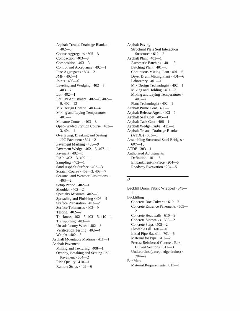
Asphalt Treated Drainage Blanket ·402—3
Coarse Aggregates · 805—3Compaction · 403—8Composition · 403—3Control and Acceptance · 402—1Fine Aggregates · 804—2JMF · 402—1Joints · 403—6Leveling and Wedging · 402—3,
403—7Lot · 402—1Lot Pay Adjustment · 402—8, 402—
9, 402—12Mix Design Criteria · 403—4Mixing and Laying Temperatures ·
401—7Moisture Content · 403—3Open-Graded Friction Course · 402—
3, 404—1Overlaying, Breaking and Seating
JPC Pavement · 504—2Pavement Marking · 403—9Pavement Wedge · 402—3, 407—1Payment · 402—5RAP · 402—3, 409—1Sampling · 402—1Sand Asphalt Surface · 402—3Scratch Course · 402—3, 403—7Seasonal and Weather Limitations ·
403—2Setup Period · 402—1Shoulder · 402—2Specialty Mixtures · 402—3Spreading and Finishing · 403—4Surface Preparation · 403—2Surface Tolerances · 403—9Testing · 402—2Thickness · 402—5, 403—5, 410—1Transporting · 403—4Unsatisfactory Work · 402—3Verification Testing · 402—4Weight · 402—5
Asphalt Mountable Medians · 411—1Asphalt Pavement
Milling and Texturing · 408—1Overlay, Breaking and Seating JPC
Pavement · 504—2Ride Quality · 410—1Rumble Strips · 403—6
Asphalt PavingStructural Plate Soil Interaction
Structures · 612—2Asphalt Plant · 401—1
Automatic Batching · 401—5Batching Plant · 401—3Continuous Mixing Plant · 401—5Dryer Drum Mixing Plant · 401—6Laboratory · 401—1Mix Design Technologist · 402—1Mixing and Holding · 401—7Mixing and Laying Temperatures ·
401—7Plant Technologist · 402—1
Asphalt Prime Coat · 406—1Asphalt Release Agent · 403—1Asphalt Seal Coat · 405—1Asphalt Tack Coat · 406—1Asphalt Wedge Curbs · 411—1Asphalt-Treated Drainage Blanket
(ATDB) · 303—1Assembling Structural Steel Bridges ·
607—15ATDB · 303—1Authorized Adjustments
Definition · 101—6Embankment-in-Place · 204—5Roadway Excavation · 204—5
B
Backfill Drain, Fabric Wrapped · 845—1
BackfillingConcrete Box Culverts · 610—2Concrete Entrance Pavements · 505—
2Concrete Headwalls · 610—2Concrete Sidewalks · 505—2Concrete Steps · 505—2Flowable Fill · 601—20Initial Pipe Backfill · 701—5Material for Pipe · 701—2Precast Reinforced Concrete Box
Culvert Sections · 611—3Underdrains (except edge drains) ·
704—2Bar Mats
Material Requirements · 811—1
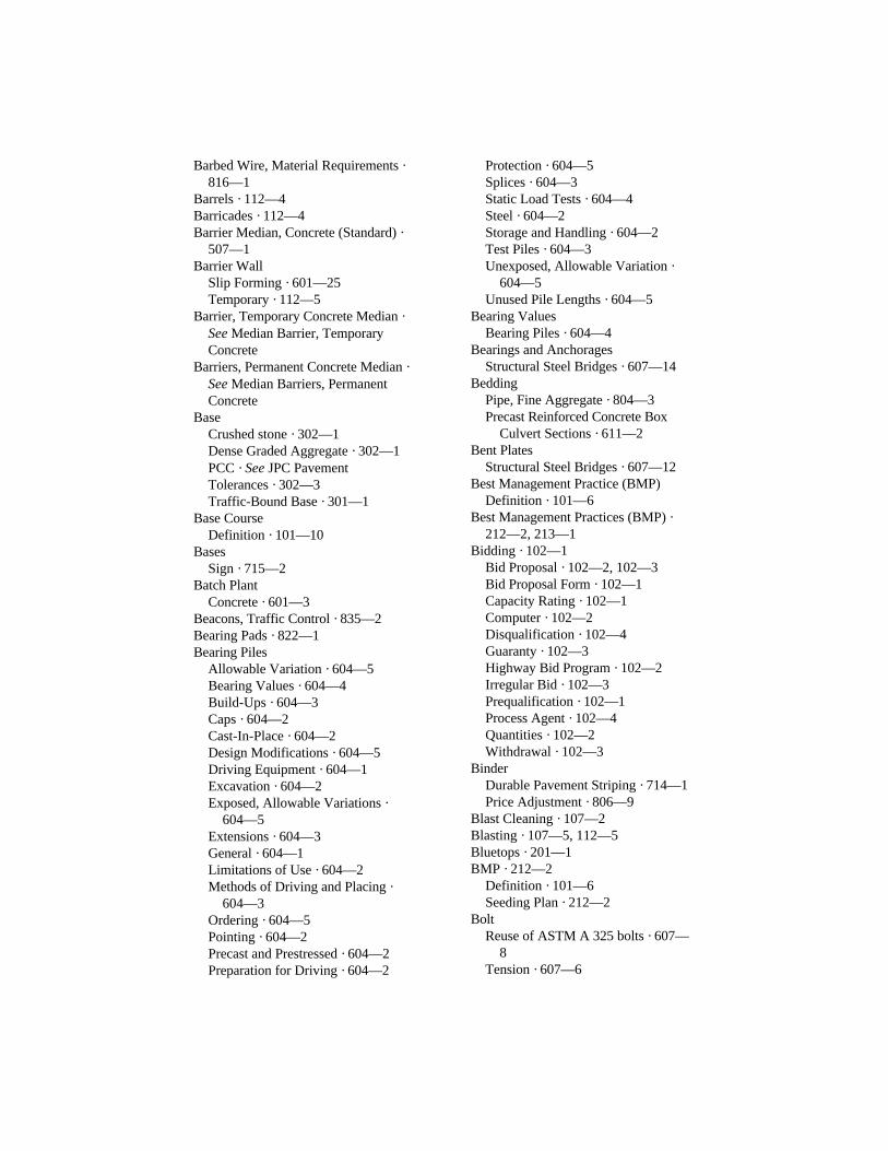
Barbed Wire, Material Requirements ·816—1
Barrels · 112—4Barricades · 112—4Barrier Median, Concrete (Standard) ·
507—1Barrier Wall
Slip Forming · 601—25Temporary · 112—5
Barrier, Temporary Concrete Median ·See Median Barrier, TemporaryConcrete
Barriers, Permanent Concrete Median ·See Median Barriers, PermanentConcrete
BaseCrushed stone · 302—1Dense Graded Aggregate · 302—1PCC · See JPC PavementTolerances · 302—3Traffic-Bound Base · 301—1
Base CourseDefinition · 101—10
BasesSign · 715—2
Batch PlantConcrete · 601—3
Beacons, Traffic Control · 835—2Bearing Pads · 822—1Bearing Piles
Allowable Variation · 604—5Bearing Values · 604—4Build-Ups · 604—3Caps · 604—2Cast-In-Place · 604—2Design Modifications · 604—5Driving Equipment · 604—1Excavation · 604—2Exposed, Allowable Variations ·
604—5Extensions · 604—3General · 604—1Limitations of Use · 604—2Methods of Driving and Placing ·
604—3Ordering · 604—5Pointing · 604—2Precast and Prestressed · 604—2Preparation for Driving · 604—2
Protection · 604—5Splices · 604—3Static Load Tests · 604—4Steel · 604—2Storage and Handling · 604—2Test Piles · 604—3Unexposed, Allowable Variation ·
604—5Unused Pile Lengths · 604—5
Bearing ValuesBearing Piles · 604—4
Bearings and AnchoragesStructural Steel Bridges · 607—14
BeddingPipe, Fine Aggregate · 804—3Precast Reinforced Concrete Box
Culvert Sections · 611—2Bent Plates
Structural Steel Bridges · 607—12Best Management Practice (BMP)
Definition · 101—6Best Management Practices (BMP) ·
212—2, 213—1Bidding · 102—1
Bid Proposal · 102—2, 102—3Bid Proposal Form · 102—1Capacity Rating · 102—1Computer · 102—2Disqualification · 102—4Guaranty · 102—3Highway Bid Program · 102—2Irregular Bid · 102—3Prequalification · 102—1Process Agent · 102—4Quantities · 102—2Withdrawal · 102—3
BinderDurable Pavement Striping · 714—1Price Adjustment · 806—9
Blast Cleaning · 107—2Blasting · 107—5, 112—5Bluetops · 201—1BMP · 212—2
Definition · 101—6Seeding Plan · 212—2
BoltReuse of ASTM A 325 bolts · 607—
8Tension · 607—6

Bolt Holes, Structural Steel Bridges ·607—2
BoltsConnections, Structural Steel Bridges
· 607—5Steel · 813—1Timber Structures · 829—1
Boring and Jacking of Encasement PipeGeneral · 706—1Materials · 706—1
Borrow ExcavationGeneral · 205—1Seed and Protect · 205—1
Brace Wire, Material Requirements ·816—1
Breaking and Seating JPC PavementBreaking, Test Section · 504—1Edge Drains · 504—2Equipment · 504—1General · 504—1Placement of Asphalt · 504—2Seating · 504—2Size Requirements · 504—1
Brick · 824—1Bridge
Definition · 101—6Bridge Barrier Wall
Slip Forming · 601—25Bridge Deck Restoration and
Waterproofing with ConcreteOverlaysLatex Admixture · 841—1
Bridge Decks, Reinforced Concrete ·See Reinforced Concrete BridgeSlabs
Bridge End Object Marker · 718—1Bridge Painting · See Structural Steel
CoatingsBridge Planking · See Wood ProductsBridge Railing, Cast Aluminum · 815—
1Bridge Restoration and Waterproofing
with Concrete OverlaysBlast Cleaning · 606—3Bridge End Transitions · 606—5Brooming · 606—5Cleaning · 606—2Damage to Structures · 606—6Epoxy-Sand Slurry · 606—5
Equipment · 606—1Expansion Dam Treatment · 606—6Field welding · 606—4Full Depth Patching · 606—4General · 606—1Hydrodemolition · 606—3Joints, Cleaning · 606—5Joints, Sealing · 606—5Latex Overlays, Existing Bridges ·
606—6Latex Overlays, New Structures ·
606—8Low Slump Concrete Overlays,
Existing Bridges · 606—8Low slump concrete overlays, new
structures, special requirements ·606—10
Material Hauling · 606—6Materials · 606—1Mixing Concrete · 606—4Partial-Depth Patching · 606—4Placing Concrete · 606—4Removal of Concrete · 606—2Restoration of Reinforcement · 606—
2Scheduling · 606—2Thickness Deficiency, Price
Adjustment · 606—11Unacceptable Work · 606—6Weather Limitations · 606—2
BridgesConcrete · See Concrete BridgesRemoval · 203—1Structural Steel · See Structural Steel
BridgesBrush Barriers · 202—1, 212—1Build-Ups
Bearing Piles · 604—3Burlap Cloth · 823—1Burlap Drag
JPC Pavement, Base, and Shoulders ·501—7
Burning · 107—2, 202—1Fire Plan · 107—2
Butyl Rubber SealantsPrecast Reinforced Concrete Box
Culvert Sections · 611—2Buy American · 106—2
C
Cable Markers · 716—2Calcium Chloride · 825—1Calendar Days · 108—2Calender Days · 108—4Camber
Box Culverts · 611—2Falsework and Forms · 601—25
Camera InspectionUnderdrains · 704—4
Camera TestingEquipment Requirements · 704—1
CapsFor Piles · 604—2
Cast Aluminum Bridge Railing · 815—1
CastingPrestressed and Precast Concrete
Products · 605—2Castings for Right-of-Way Markers ·
813—1Cast-In-Place (CIP), Retaining wall ·
613—2Catch Basins · See Small Drainage
StructuresFilling and Capping · See Filling and
Capping AbandondedUnderground Structures
CementGeneral · 601—1, 724—6, 802—2Mills · 724—5, 802—1
Cement FactorConcrete · 601—8
Cement Stabilized Roadbed · SeeChemically StabilizedRoadbed:General
Cement Treated Drainage Blanket ·303—1
CertificationPrestress Concrete Plants, Special
Requirements · 605—5Prestressed and Precast Plants ·
605—1Quantities · 109—5
Chain Link Fencing MaterialsBarbed Wire · 817—1Brace Connections · 817—1Fabric · 817—1
Fabric Ties · 817—1General · 817—1Hog Rings and Tension Wire · 817—
1Post Caps · 817—1Posts, Rails, Gate Frames, and
Expansion Sleeves · 817—1Channel Change
Planting · 724—1Channel Changes
General · 206—1Channel Lining
Class IA · 703—2Class II · 703—2Class III · 703—2Class IV · 204—2, 703—2General · 703—2Geotextile · 214—1Gradation · 805—6Materials · 703—1Mattress Units · 703—2
Channel Preservation · 603—1Chemically Stabilized Roadbed · 208—
1Compaction · 208—3Curing · 208—3Materials · 208—1Mixing · 208—2Temperature and Weather Lmitations
· 208—1Claims · 105—9, 107—6Clean Cross Drains · 209—2Clean Up · 104—3Cleaning Steel Bridges (Maintenance) ·
See Maintenance Cleaning andPainting Steel Bridges
Clearing and GrubbingClearing Plans · 107—2General · 202—1
Coal · 104—3, 204—2Coarse Aggregate
Asphalt Mixtures, Finer Than No.200 (seals) · 805—4
Channel Lining, Class IA · 805—6Channel Lining, Class II · 805—6Channel Lining, Class IV · 805—6Channel Lining, Cylopean Stone
Riprap · 805—5Channel Lining, General · 805—5
Crushed Stone Base (CSB)Materials Requirement · 805—4
Dense Graded Aggregate (DGA) ·805—4
Free Draining Bedding and Backfill ·805—4
Granular Embankment · 805—5Maintenance · 805—6Non-specification Gradations · 805—
6Reinforced Fill Material, General ·
805—5Rock Drainage Blanket · 805—4Slope Protection, Crushed Aggregate
· 805—5Slope Protection, Cylopean Stone
Riprap · 805—5Slope Protection, General · 805—5Slope Protection, Stone for Gabions ·
805—6Structure Granular Backfill · 805—5Surfacing · 805—6Traffic Bound Base · 805—6Underdrains · 805—4
Coarse Aggregates · 805—1Approval · 805—1Asphalt Mixtures and Seals,
Absorption · 805—3Asphalt Mixtures and Seals, Crushed
Particles · 805—3Asphalt Mixtures and Seals, General
· 805—3Asphalt Mixtures, Flat and Elongated
· 805—4Asphalt Mixtures, Polish-Resistant
Aggregate · 805—4Concrete, General · 805—2Concrete, Lightweight Aggregate ·
805—3Erodible or Unstable Material ·
805—2General Requirements · 805—1Gradation · 805—2Physical Properties · 805—2Sampling and Testing · 805—16Shale · 805—1Soundness · 805—1
CofferdamsFoundation Seals · 603—3General · 603—2
CompactionAsphalt Pavement · 403—8Chemically Stabilized Roadbed ·
208—3Crushed Stone Base (CSB) · 302—1Dense Grade Aggregate (DGA) ·
302—1Embankment · 206—2Option A · 403—8Option B · 403—8Subgrade · 207—1
Completion Date · 108—5Compressive Strength
Concrete · 601—8Department Testing · 601—13
ConcreteAdmixtures · 601—1, 601—15,
802—1Air Content by Class · 601—8Artificial Heating · 601—21Barrier, Temporary · 112—4, 509—1Barriers, Permanent · 508—1Cement Factor by Class · 601—8Class M Strength Deficiency, Price
Adjustment · 601—34Classes · 601—8, 601—14Compressive Strength by Class ·
601—8Consolidation · 601—18Construction Joints · 601—21Construction Requirements · 601—5Curbs and Gutters · 506—1Curing · 601—30Curing, Blankets · 601—31Curing, Wet · 601—30Delivery · 601—16Entrance Pavements · 505—1Equipment · 601—1Falsework · 601—22Fine Aggregates · 804—1Flowable Fill · 601—9Fly Ash · 601—11Forms · 601—1General · 601—1Ground Granulated Blast Furnace
(GGBF) Slag · 601—12Grout · 601—9Handling Materials · 601—5Identification Stencil · 601—34JPC Pavement 24/48/72 · 502—1
JPC Pavement, Base, and Shoulders ·501—1
Materials · 601—1Measuring Proportions · 601—13Medians · 507—1Microsilica · 601—12Mineral Admixtures · 601—11Mix Design · 601—6Mix Requirements · 601—8Mixing · 601—16Mortar · 601—9Opening to Traffic · 601—27Placing · 601—18Placing Under Water · 601—19Prepour Meeting · 601—5Primary Uses · 601—14Producer Responsibilities · 601—6Proportioning Requirements · 601—8Records · 601—6Removal of Falsework · 601—25Removal of Forms · 601—25Scales · 601—2Seal · 601—20Sealing and Patching With Epoxy
Resin · 510—1Self-Consolidating · 601—9Sidewalks · 505—1Significant Loads, Time Required ·
601—29Slope Wall · 703—1Slump · 601—15Slump by Class · 601—8Steps · 505—1Surface Finish, Floated · 601—33Surface Finish, General · 601—32Surface Finish, Masonry Coating ·
601—32Surface Finish, Ordinary · 601—32Temperature Limitations · 601—5Trip Tickets · 601—6Vibrating · 601—18Weather Limitations and Protection ·
601—21Concrete Admixtures · See Admixtures
for ConcreteConcrete Box Culverts
Apron Walls · 610—1Drainage · 610—2Extensions To Existing · 610—2
Footings · 610—1General · 610—1Headwalls · 610—1Placing Concrete · 610—2Placing Fill · 610—2Removing Forms · 610—2Surface Finish · 610—2
Concrete BridgesClasses of Concrete · 608—1Falsework and Forms · 608—1Foundation · 608—1General · 608—1Identification Plate · 608—2Inspection Facilities · 608—2Layout · 608—2Materials · 608—1Permissable Finish Variations ·
608—3Piers and Abutments · 608—2Placing Anchor Bolts · 608—2Placing Concrete in Substructure ·
608—1Placing Steel Reinforcement in
Substructure · 608—1Placing Steel Reinforcement in
Superstructure · 608—2Placing Superstructure · 608—2Protection · 608—2Setting Expansion Devices · 608—2Superstrucure, General Requirements
· 608—2Concrete Curing Materials
Burlap Cloth · 823—1Curing Blankets · 823—2General · 823—1Liquid Membrane Forming
Compounds · 823—1Price Adjustment · 823—1Waterproof Paper · 823—1White Burlap - Polyethylene Sheet ·
823—1White Polyethylene Film · 823—1
Concrete HeadwallsFootings · 610—1General · 610—1Placing Concrete · 610—2Placing Fill · 610—2Removing Forms · 610—2Surface Finish · 610—2
Concrete Members

Prestressed and Precast · SeePrestressed and Precast ConcreteProducts
Concrete Overlays · See BridgeRestoration and Waterproofing withConcrete Overlays
Concrete PavingStructural Plate Soil Interaction
Structures · 612—2Concrete Pipe · See Culvert PipeConcrete Placement
JPC Pavement, Base, and Shoulders ·501—4
Concrete PlantBatching Equipment · 601—3Batching Equipment, JPC Pavement,
Base, and Shoulders · 501—1Personnel · 601—6
Concrete ProducerQuality Control · 601—6
Concrete Seal · 601—20Concrete Technician · 601—6Conduit
Roadway Lighting Materials · 834—1
Conduit InstallationRoadway Lighting · 716—1
Cones · 112—4Conglomerate Sand · 804—1Connections
Pin, Structural Steel Bridges · 607—15
ConsolidationConcrete · 601—18JPC Pavement, Base, and Shoulders ·
501—5Construction
Maintenance and Control of Traffic ·112—4
Construction Loads · 701—5Contract · 103—1
Award · 103—1Bond · 103—1Coordination of Documents · 105—3Default and Termination · 108—7Definition · 101—7Emergency Deferment · 108—7Emergency Termination · 108—7Execution · 103—2
Failure to Execute · 103—2Termination · 108—8Time · 108—3
Contraction JointsNon-Structural Concrete · 601—30
ContractorCooperation · 105—3Definition · 101—7Insurance · 107—7Liability · 105—3Maintenance · 105—8, 212—3Responsibility for Work · 107—6Schedule · 108—1Utility Responsibilities · 107—6Wage Requirements · 107—3
Control of Work · 105—1Control Strips
DGA and CSB Base · 302—1Controlling Item
Definition · 101—7Controlling Operation
Definition · 101—7Cored Hole Drainage Box Connector
General · 705—1Materials · 705—1
Corrective Seeding · 108—6Cost-Plus
See Force Account · 109—7Coupling Bands · 810—2Crash Cushions
Temporary · 112—5Cross Drains
Cleaning · 209—2Crown Vetch · 212—2Crushed Aggregate Slope Protection ·
703—2Crushed Sand · 804—1Crushed Stone Base (CSB) · 805—4
General · 302—1Tolerances · 302—3
CSB · 302—1Culvert
Definition · 101—7Culvert Pipe
Asphalt Coating · 701—3Backfill Material · 701—2Backfill, Concrete · 701—5Backfill, Metal · 701—5Backfill, Thermoplastic · 701—5
Concrete, Material Requirements ·810—1
Construction Loads · 701—5Cover, Minimum · 701—5Cover, Temporary · 701—5End Structures · 701—6Extensions to Existing Pipe · 701—6Extra Protection · 810—1Flowable Fill · 701—5Foundation · 701—2General · 701—1Geotextile Fabric Use · 701—5Identification and Markings,
Concrete · 810—1Initial Backfill, General · 701—5Installation, Concrete · 701—3Installation, Metal · 701—3Installation, Structural Plate · 701—4Installation, Thermoplastic · 701—4Joints, Concrete · 701—4Joints, Metal · 701—4Joints, Thermoplastic · 701—5Materials · 701—1Metal, Coating · 810—2Metal, Coupling Bands · 810—2Metal, Material Requirements ·
810—2Price Adjustment for Deflection ·
701—8Removing · 701—6Removing and Relaying · 701—6Testing · 701—5Thermoplastic, Material
Requirements · 810—3Trenching · 701—3Undercutting · 701—7
Culvert Pipe Equivalent · See CulvertPipe
Curb and Gutter (combination),ConcreteConstruction Requirements · 506—1
Curbs and Gutters, ConcreteCurb and Gutter (combination) ·
506—1Forms · 506—1General · 506—1Header Curb · 506—1Integral Curb · 506—2Removal · 203—1
Valley Gutter · 506—1Curing
Cement Treated Drainage Blanket ·303—3
Chemically Stabilized Roadbed ·208—3
Concrete Sidewalks · 505—2Curing Blankets · 823—2Curing Compound
Price Adjustment · 823—1Curing Concrete
Blankets · 601—31Concrete Entrance Pavements · 505—
2Concrete Steps · 505—2General · 601—30JPC Pavement 24/48/72 · 502—1JPC Pavement, Base, and Shoulders ·
501—8Latex Concrete Overlays · 606—7Low Slump Concrete Overlays ·
606—9Membrane · 601—31Prestressed and Precast Products ·
605—6Prestressed Members · 605—6Reinforced Concrete Bridge Slabs ·
609—7Wet Curing · 601—30
Curing JPC PavementBlankets · 501—9Wet Burlap · 501—9White Membrane · 501—8
Curving With Heat, Steel · 607—9Cut-Back Asphalt Emulsion Primer ·
806—13Cutting With Flame, Steel · 607—9Cyclopean Stone Riprap · 703—2,
805—5
D
DamageExisting Roadway · 105—4Repair · 107—6
DBE · 103—2Decks, Reinforced Concrete Bridge ·
See Reinforced Concrete BridgeSlabs
Defective Material · 106—2Defective Work · 105—2Definitions · 101—5Deflection Testing · 701—5De-Icers
Calcium Chloride, Solid (Type S) ·825—1
General · 825—1Sodium Chloride · 825—1
Delineator Post · 838—1Delineators · 830—1Delivery of Concrete
Discharge Time · 601—16General · 601—16JPC Pavement, Base, and Shoulders ·
501—4Demobilization · 110—1Dense Graded Aggregate (DGA)
General · 302—1Materials Requirement · 805—4Tolerances · 302—3
DesignRetaining Walls · 613—1
Design QuantityRoadway Excavation · 204—5
Detour · 112—4Definition · 101—7
Dewatering · 601—20Foundation Seals · 603—3Structures · 603—2
DGA · 302—1Diamond Grinding JPC Pavement
Alignment Tolerances · 503—2Equipment · 503—1General · 501—9, 503—1Joints, Preserving Existing Seals ·
503—1Joints, Resealing Existing · 503—1Pavement Marking · 503—2Ride Quality · 503—2Test Section · 503—1Texture · 503—2
Diesel Fuel Price Adjustment · 109—11Differing Site Conditions · 104—2Direct Tension Indicators
Material Rrequirements · 607—1Structural Steel Bridges, Use · 607—
8Disadvantaged Business Enterprise ·
103—2
Discharge TimeDelivery of Concrete · 601—16
DisposalWaste Material · 204—3
Dispute · 105—9Resolution · 113—2
Ditches · 204—2Ditches, Paved · See Paved DitchesDitching · 209—1Ditching and Shouldering
General · 209—1Diversion
Definition · 101—7General · 112—4
Dowel Bar Sleeves · 811—2Dowel Bars · 811—2
Medians, Concrete · 507—1Transverse Expansion Joints, JPC
Pavement · 501—10Drain Pipe, Slotted · 810—2Drainage
Concrete Box Culverts · 610—2Pavement · 303—1Reinforced Concrete Bridge Slabs ·
609—5Retaining Walls · 613—2Structure · 603—2Subgrade · 209—2Wick Drains · 711—1
Drainage BlanketsEmbankment · 210—1Embankment, Materials Requirement
· 804—4, 805—4Geotextile · 214—2Pavement · See Pavement Drainage
BlanketsDrainage Structures
Adjusting · 403—3, 408—2Drainageways · 213—4Drawings
Falsework · 601—22Roadway Lighting · 716—2
DrivingBearing Piles · 604—3
Drop-Offs · 112—3, 112—5Durable Pavement Striping
Layout · 714—1Price Adjustment · 714—5Tape, Type I · 714—1
Thermoplastic · 714—1Weather and Temperature
Limitations · 714—3Dust Control · 107—1
E
Edge Drain Outlet Headwalls · SeeSmall Drainage Structures
Edge Drains · See Underdrains. SeePavement Edge Drains
Edge PlaningStructural Steel Bridges · 607—9
Edge SlumpJPC pavement, base, and shoulders ·
501—14Edging
Concrete Entrance Pavements · 505—1
Concrete Sidewalks · 505—1JPC Pavement, Base, and Shoulders ·
501—7Elastomeric Bearing Pads · 822—1Electronic Surveying · 201—2Embankment
Channel Changes · 206—1Compaction · 206—2Embankment-in-Place · 206—2Foundations · 206—1General · 206—1Materials · 206—1
Embankment Drainage BlanketsCoarse Aggregate · 805—4Fine Aggregate · 804—4Rock · 210—1Sand · 210—1
Embankment Foundation StabilizationGeotextile · 214—1
Embankment-in-Place · 206—2Emulsified Asphalt
General · 806—10Price Adjustment · 806—10
End Connector AnglesStructural Steel Bridges · 607—11
End Structures · See Also ConcreteHeadwallsConcrete Box Culverts · 610—1Culvert Pipe · 701—6
Precast Reinforced Concrete BoxCulvert Sections · 611—3
Structural Plate Soil InteractionStructures · 612—3
End Treatments, Material Requirements· 814—3
EngineerAuthority · 105—1Definition · 101—8
Enterprise Zone · 107—3Entrance Pavements, Concrete
Backfilling · 505—2Curing · 505—2Edging · 505—1Forming, General · 505—1Forming, Side Form · 505—1Forming, Slip Form · 505—1General · 505—1Joints · 505—2Straightedging · 505—1
Entrance Pipe · See Culvert PipeEntrance Pipe Equivalent · See Culvert
PipeEpoxy
Coated Steel Reinforcement · 602—2Epoxy Bond Coat · 511—1Epoxy Coating
Steel Reinforcing · 811—3Epoxy Resin Systems · 826—1Epoxy Seal Coats · 804—3Epoxy-Sand Slurry
Bridge Restoration andWaterproofing with ConcreteOverlays · 606—5
Fine Aggregate · 804—3Equipment
Pipeline Inspection Camera (edgedrains) · 704—1
Rental · 108—1Rental Rates · 109—7Spreaders, JPC Pavement, Base, and
Shoulders · 501—2Erection Plans
Structural Plate Soil InteractionStructures · 612—1
Erodible MaterialCoarse Aggregates · 805—2
Erosion ControlBMP · 212—2
Brush Barrier · 212—1Crown Vetch · 212—2Erosion Control Blanket · 212—2General · 212—1Hydromulch · 212—2Seeding and Protection, Permanent ·
212—1Seeding and Protection, Temporary ·
213—4Sod · 212—4Temporary Mulch · 213—4Topdressing · 212—2
Erosion Control BlanketGeneral · 212—2Material Requirements · 827—3
Erosion Control MaterialsAgricultural Limestone · 827—1Asphalt Materials for Mulch · 827—
3Erosion Control Blanket · 827—3Fertilizer · 827—1General · 827—1Mulch Materials · 827—2Netting and Staples · 827—4Seed · 827—1Sod · 827—4Temporary Silt Fence · 827—3Topsoil · 827—4
Excavated Materials Use · 204—2Excavation
Bearing Piles · 604—2Precast Reinforced Concrete Box
Culvert Sections · 611—1Roadway and Drainage · 204—1
Expansion Devices · 608—2Expansion Joints
Concrete Structures · 601—29Neoprene, Reinforced Concrete
Bridge Slabs · 609—5Non-Structural Concrete · 601—30Reinforced Concrete Bridge Slabs ·
609—3Explosives · 107—5Extensions
Bearing piles · 604—3Concrete Box Culverts · 610—2Culvert Pipe · 701—6
Extra Length Posts, Guardrail · 719—1Extra Protection
Culvert Pipe, Concrete · 810—1
Extra WorkDefinition · 101—8General · 104—2Payment for · 109—7
F
FabricGeotextile Construction · 214—1
Fabric Ties, Material Requirements ·817—1
Fabric Wrapped Backfill Drain · 845—1Fabric Wrapped Drains
Retaining Walls · 613—2Fabric-Wrapped Backfill Drain · 603—
2Facing of Bearing Surfaces
Structural Steel Bridges · 607—11Fall Protection · 107—1Falsework
Camber · 601—25Concrete Bridges · 608—1Design · 601—23Drawings · 601—22General · 601—22Removal of · 601—25Removal of, Structural Steel Bridges ·
607—15Structural Steel Bridges · 607—14
FenceGates · 721—2General · 721—1Remove · 722—1Replace · 722—1Reset · 722—1Setting Posts · 721—1
Fence Posts, Material Requirements ·817—1
Fencing MaterialsChain Link · See Chain Link Fencing
MaterialsWoven Wire · See Woven Wire
Fencing MaterialsFertilizer · 827—1Fiberglass Membrane · 808—1Field Laboratory
Asphalt Plant · 106—2, 401—1Concrete · 106—2, 107—2General · 106—2
Filling and Capping AbandonedUnderground Structures (Diameters24 inches or Less)Inlets · 708—1
Filling and Capping AbandonedUnderground Structures (Diameters24 Inches or Less)Catch Basins · 708—1General · 708—1Manholes · 708—1Materials · 708—1Wells · 708—1
Filling and Capping AbandonedUnderground Structures (DiametersOver 24 inches)Inlets · 708—1Manholes · 708—1
Filling and Capping AbandonedUnderground Structures (DiametersOver 24 Inches)Catch Basins · 708—1General · 708—1Materials · 708—1Wells · 708—1
Final DressingClass A · 211—1Class B · 211—1General · 211—1
Final EstimateDefinition · 101—8General · 109—9
Final Inspection · 105—8Acceptance · 105—8
Final Payment · 109—9Final Release · 109—10Final Strike-Off
JPC Pavement, Base, and Shoulders ·501—5
Fine AggregatesApproval · 804—1Asphalt Mixtures, Combined
Aggregate · 804—2Asphalt Mixtures, General · 804—2Asphalt Mixtures, Mineral Filler ·
804—2Asphalt Mixtures, Polish Resistant
Aggregate · 804—2Asphalt Mixtures, Sand · 804—2Backfill · 804—4Concrete · 804—1
Conglomerate Sand · 804—1Crushed Sand · 804—1Drainage · 804—4Embankment Drainage Blanket ·
804—4Epoxy Sand Slurry · 804—3Epoxy Seal Coats · 804—3General · 804—1Mineral Filler · 804—1Mortar Sand · 804—1, 804—3Natural Sand · 804—1Non-specification Gadations · 804—4Pipe Bedding · 804—3Sampling and Testing · 804—6Underdrains · 804—4
FinishSurface · See Surface Finish
FinishingJPC Pavement, Base, and Shoulders ·
501—5Reinforced Concrete Bridge Slabs ·
609—7Structural Steel Bridges · 607—9
Finishing MachinesConcrete Overlays · 606—1Reinforced Concrete Bridge Slabs ·
609—1Fire Plan · 107—2Fixed Completion Date · 108—2Fixed Joints
Reinforced Concrete Bridge Slabs ·609—3
Flame CuttingStructural Steel Bridges · 607—9
Flashing Arrow Board · 112—4Flexible Delineator Post · 838—1Floated Surface Finish
Concrete · 601—33Floating
JPC Pavement, Base, and Shoulders ·501—6
Flowable FillPipe Backfill · 701—5Placing · 601—20Proportioning and Requirements ·
601—9Pumping · 601—20
Flume InletsGeneral · 709—1

Materials · 709—1Fly Ash · 601—11, 724—5, 801—1
Material Requirements · 844—1Non-Specification · 844—2Price Adjustment · 844—2Seasonal Limitations · 601—21
Footing Excavation · 603—1Footings
Concrete Box Culverts · 610—1Concrete Headwalls · 610—1Signs · 715—2
Force Account · 109—7Definition · 101—8
ForgingsStructural Steel Bridges · 607—13
Formal Acceptance · 105—8Definition · 101—8
Formal Partnering · 114—1Forming
Concrete Entrance Pavements · 505—1
Concrete Median Barriers, FixedForm · 508—1
Concrete Median Barriers, Slip ·508—2
Concrete Sidewalks · 505—1General · 601—23JPC Pavement, Base, and Shoulders ·
501—4Non-Structural Concrete · 601—25Prestressed and Precast Concrete
Products · 605—2Reinforced Concrete Bridge Slabs ·
609—1Structures · 601—23
Forming, SlipBridge barrier wall · 601—25Concrete Entrance Pavement · 505—
1Concrete Sidewalks · 505—1Non-Structural Concrete · 601—25
FormsCamber · 601—25Concrete Bridges · 608—1Concrete Curbs and Gutters · 506—1Concrete, General · 601—1Entrance Pavements, Concrete ·
505—1JPC Pavement, Base, and Shoulders ·
501—1
Median Barriers, Permanent Concrete· 508—1
Removal of · 601—25Removal of, Box Culverts · 610—2Removal of, Headwalls · 610—2Removal of, JPC Pavement, Base,
and Shoulders · 501—7Removal of, Prestressed Members ·
605—6Sidewalks, Concrete · 505—1Stay-in-Place Metal · 601—2Steps, Concrete · 505—1
FoundationConcrete Bridges · 608—1Embankment · 206—1Pipe · 701—2Retaining Walls · 613—1
Foundation PreparationBackfilling · 603—2Cofferdams · 603—2Drainage · 603—2Footing Excavation · 603—1General · 603—1
Foundation Seals · 603—3Foundation Undercut · 603—4Fuel Price Adjustment · 109—11Full Depth Patching
Bridge Restoration andWaterproofing with ConcreteOverlays · 606—4
G
GabionAggregate · 805—6Walls · 613—2Wire · 813—6
Gates, Material Requirements · 816—2Geotextile Construction · 214—1
Channel Lining · 214—1Drainage Blankets · 214—2Embankment Foundation
Stabilization · 214—1Field Splices · 214—1Laps · 214—1Slope Protection · 214—1Subgrade · 214—1Underdrains · 214—1
Geotextile Fabric

Culvert Pipe · 701—5Fastener Pins · 843—3General · 843—1Price Adjustment · 843—3
GGBF Slag · 601—12, 724—5, 844—1,801—1, 844—1
Glass Beads, Type I · 839—1Gradation
Channel Linings · 805—6Granular Embankment · 805—5Structure Granular Backfill · 805—5
Granular EmbankmentGradation · 805—5
Grass · 827—1Gravity Wall · 613—1Gray Iron Castings · 813—1Ground Granulated Blast Furnace Slag
(GGBF) See GGBF SlagGround Rods · 834—3Grout
Proportioning and Requirements ·601—9
Grouting and Epoxy Bond CoatDrilling · 511—1Epoxy Bond Coat · 511—1General · 511—1Grouting · 511—1Inserting Bars · 511—1
GuardrailAdjust · 719—2Extra Length Posts · 719—1General · 719—1Install · 719—1Material Requirements · 814—1Placing Rail · 719—1Relocate · 719—2Remove · 719—2Salvaged · 719—2Temporary · 719—2
H
HammersPile Driving · 604—1
HandrailInstall · 720—1Material Requirements · 813—5
Hardware for Timber Structures · 829—1
HaulingGeneral · 105—4Over Railways · 107—4Overloads · 109—6
HDPE Pipe · 701—1Header Curb, Concrete
Construction Requirements · 506—1Headwalls · See EndstructuresHeadwalls, Concrete · See Concrete
HeadwallsHeadwalls, Edge Drain Outlet · See
Small Drainage StructuresHealth · 107—1Heat Curving
Structural Steel Bridges · 607—9High Range and Retarding Water-
Reducing Admixtures · 802—1High Range Water-Reducing
Admixtures · 802—1Highway
Definition · 101—8Highway Bid Program · 102—2Historic Preservation · 205—1Holidays · 101—8Hook Bolts
General · 512—1Material Requirements · 512—1
Hot Poured Elastic SealsJPC Pavement Uses · 501—12
Hydrated Lime · 824—1Hydrodemolition · 606—3Hydromulch · 212—2
I
IdentificationMarking, Concrete Pipe · 810—1Marking, Maintenance Cleaning and
Painting Steel Bridges · 614—3Plates, Concrete Bridges · 608—2Plates, Structural Steel Bridges ·
607—20Stencil, Concrete · 601—34
Informal Partnering · 114—1Inlets · See Small Drainage Structures
Filling and Capping · See Filling andCapping AbandondedUnderground Structures
Inspection
General · 105—1Inspector
Authority · 105—1Definition · 101—9
Integral CurbConstruction Requirements · 506—2
International Roughness IndexAsphalt Pavement · 410—1JPC Pavement · 501—15
Intersection Markings · 717—1IRI
Asphalt Pavement · 410—1JPC Pavement · 501—15
J
Joint Materials · 807—1Fillers, Cork Expansion · 807—4Fillers, General · 807—4Fillers, Oil Asphalt · 807—4Fillers, Preformed Asphalt Expansion
· 807—4Fillers, Preformed Sponge Rubber ·
807—4Sealers, General · 807—1Sealers, Hot-Poured Elastic · 807—1Sealers, Preformed Compression ·
807—1Sealers, Preformed Expansion ·
807—2Sealers, Rigid Pipe · 807—2Sealers, Silicone rubber · 807—3
Joint ResealingDiamond Grinding JPC Pavment ·
503—1JPC Pavement · 501—13
Joint Sealant TypesJPC Pavement, Base, and Shoulders ·
501—11Joint Sealing
JPC Pavement, Base, and Shoulders ·501—11
Reinforced concrete bridge slabs ·609—4
Joint Seals, TemporaryJPC Pavement · 501—14
JointsAsphalt Pavement · 403—6
Concrete Entrance Pavements · 505—2
Concrete Sidewalks · 505—1Concrete, General · 601—29Construction (Concrete) · 601—21Construction (Concrete), Bonding of
Structural · 601—22Construction (Concrete), Non-
Structural · 601—22Construction (Concrete), Structural ·
601—21JPC Pavement, Base, and Shoulders ·
501—9Median Barriers, Permanent Concrete
(fixed form) · 508—1Median Barriers, Permanent Concrete
(precast) · 508—3Median Barriers, Permanent Concrete
(slip form) · 508—2Non-Structural, Contraction · 601—
30Non-structural, Expansion · 601—30Pipe · 701—4Precast Reinforced Concrete Box
Culvert Sections · 611—2Structural Steel Bridges · 607—11Structures, Expansion · 601—29
JPC PavementAdmixtures · 501—3Breaking and Seating · 504—1Burlap Drag · 501—7Care, Storage, and Handling of
Materials · 501—3Consolidation · 501—5Curing Blankets · 501—9Curing, General · 501—8Delivery of Concrete · 501—4Diamond Grinding · 501—9, 503—1Edge slump · 501—14Edging · 501—7Final Strike-Off · 501—5Finishing, General · 501—5Floating · 501—6Forming · 501—4Forms · 501—1General · 501—1Hand Finishing · 501—6Joint Resealing · 501—13Joint Sealant Types · 501—11
Joint Sealant, Self-Leveling SiliconeRubber · 501—13
Joint Sealant, Silicone Rubber ·501—12
Joint Sealing, General · 501—11Joint Seals, Preformed Neoprene ·
501—12Joint Seals, Temporary · 501—14Joints, General · 501—9Joints, Longitudinal · 501—9Joints, Longitudinal Expansion ·
501—11Joints, Transverse Construction ·
501—11Joints, Transverse Contraction ·
501—11Joints, Transverse Expansion · 501—
10Machine Finishing · 501—6Materials · 501—1Mixing · 501—4Opening to Traffic · 501—15Placing Concrete · 501—4Preparation of Aggregate Base
Course · 501—4Producer Responsibilities · 501—3Proportioning · 501—3Removing Forms · 501—7Ride Quality · 501—14RIDE QUALITY, PRICE
ADJUSTMENT · 501—17Rumble Strips · 501—7Slip Form Finishing · 501—5Slip Form Pavers · 501—1Slump · 501—4Station Number Stencil · 501—7Surface Correction · 501—6Surface Tolerance Testing, General ·
501—14Texturing · 501—7Thickness Deficiency, Payment
Adjustment · 501—17Thickness Tolerance · 501—16Weather Limitations · 501—3Wet Burlap Curing · 501—9White Membrane Curing · 501—8
JPC Pavement 24/48/72Admixtures · 502—1Curing · 502—1
Delay of Opening, Price Adjustment ·502—3
General · 502—1Opening to Traffic · 502—2Placing · 502—1Strength Testing · 502—2
JPC Shoulders · See JPC PavementJunction Boxes · See Small Drainage
Structures
K
KRMCA · 601—6
L
Landscaping · See PlantingLandslides · 204—2Lane Closure, Long Term · 112—4Laps
Erosion Control Blanket · 212—3Geotextile Construction · 214—1
Lateral Drains · 209—2Latex Admixture · 841—1Latex Concrete Overlays
Consolidating · 606—7Curing · 606—7Finishing · 606—7Finishing Machine · 606—1General · 606—6New Structures, Special
Requirements · 606—8Placing Concrete · 606—7Prewetting and Grout-Bond Coat ·
606—6Proportioning and Requirements ·
606—6Laying Sections
Precast Reinforced Concrete BoxCulvert Sections · 611—2
LayoutConcrete Bridges · 608—2Durable Pavement Striping · 714—1Planting · 724—2Thermoplastic Intersection Markings
· 717—1Lead Plates · 813—1Legal Responsibilities · 107—1
Leveling and Wedging · 403—7Liability
Insurance · 107—7Personal · 107—7
Licenses · 107—3Lighting Standard, Installation · 716—2Lighting, Roadway · See Roadway
LightingLighting, Roadway (Materials) · See
Roadway Lighting MaterialsLightweight Aggregate · 805—3Lime Stabilized Roadbed · See
Chemically Stabilized RoadbedLimestone, Agricultural · 827—1Liquidated Damages · 105—9, 108—6List of Approved Materials · 106—3Load Transfer Assemblies · 811—1Load Transfer Devices
Transverse Expansion Joints, JPCPavement · 501—10
LoadingConcrete, Time Required · 601—29
Longitudinal Expansion JointsJPC Pavement · 501—11
Longitudinal JointsJPC Pavement · 501—9
Low Slump Concrete Overlays · 606—8Curing · 606—9Finishing Machine · 606—1Grout-Bond Coat · 606—8New structures, special requirements
· 606—10Placing Concrete · 606—9Proportioning and Requirements ·
606—8Lumber · See Wood ProductsLuminaires · 834—2
M
Mailbox Turnouts · 209—2Maintenance · 105—8Maintenance Cleaning and Painting
Steel BridgesGeneral · 614—1Identification Marking · 614—3Maintaining Traffic · 614—2Paint Application · 614—2Paint Mixing · 614—2
Paint Thinning · 614—2Prosecution of The Work · 614—1Responsibility for Damage · 614—1Seasonal and Weather Limitations ·
614—1Surface Preparation · 614—2Unsatisfactory Work · 614—3
Major ItemDefinition · 101—9
Malleable Castings · 813—1Manhole Risers · 813—1Manhole Steps · 710—1Manholes · See Also Small Drainage
StructuresAdjusting · 403—3, 408—2Adjusting Rings · 710—3Filling and Capping · See Filling and
Capping AbandondedUnderground Structures
MarkersRight-of-Way · 723—1
Masonry Coating FinishConcrete · 601—32
Masonry Coating Material · 828—1Masonry Materials
Concrete Brick · 824—1General · 824—1Hydrated Lime · 824—1Precast Reinforced Manhole Sections
· 824—1Sewer and Manhole Leveling Brick ·
824—1Units for Catch Basins and Manholes
· 824—1Match Marking
Structural Steel Bridges · 607—4Materials
Certification · 106—2Control of · 106—1Defective · 106—2Department Furnished · 106—3List of Approved · 106—3Rights in and Use of · 104—3Storage · 106—3
Materials (Care, Storage, and Handling)Concrete, General · 601—5General · 106—3PCC Pavement, Base, and Shoulders
· 501—3
Precast Reinforced Concrete BoxCulvert Sections · 611—1
Prestressed and Precast ConcreteProducts · 605—10
Steel Reinforcement · 602—1Structural Plate Soil Interaction
Structures · 612—1Structural Steel Bridges · 607—14
Mattress Unit Wire · 813—6Mattress Units · 703—2Measurement · 109—1
Design Quantity · 109—1Lump Sum · 109—1Station · 109—1Volumes · 109—1
MeasuringConcrete Proportions · 601—13
Median Barrier, Temporary ConcreteConstruction Requirements · 509—1General · 509—1Materials · 509—1
Median Barriers, Permanent ConcreteFixed Form Construction · 508—1Forms · 508—1General · 508—1Joints (fixed form) · 508—1Joints (precast) · 508—3Joints (slip form) · 508—2Precast Construction · 508—2Slip Form Construction · 508—2
Median, Concrete Barrier (Standard) ·See Barrier Median, Concrete(Standard)
Median, Mountable Concrete · SeeMountable Median, Concrete
MembersPrestressed and Precast Concrete ·
See Prestressed and PrecastConcrete Products
Metal Handrail · 720—1Metric
English Unit Conflicts · 104—3Microsilica
General · 601—12Material Requirements · 844—1
Mill InspectionStructural Steel Bridges · 607—13
Milling and TexturingAsphalt Pavement · 408—1
Mineral AdmixturesGeneral · 601—11Ground Granulated Blast Furnace
(GGBF) Slag · 601—12Microsilica · 601—12
Mineral Admixtures for ConcreteFly Ash · 844—1General · 844—1GGBF · 844—1Microsilica · 844—1
Mineral Filler · 804—1Minor Item
Definition · 101—9Miscellaneous Metals
for Structural Steel Bridges · 607—1Miscellaneous Metals, Material
Requirements · 813—1Misfits
Structural Steel Bridges · 607—15Mix Designs
Concrete · 601—6Mixers, Concrete
Batch · 601—3Central · 601—4Continuous · 601—3General · 601—3JPC Pavement, Base, and Shoulders ·
501—1Truck · 601—4
MixingConcrete for Prestressed and Precast
Members · 605—2Mixing Concrete
Bridge Overlays · 606—4General · 601—16JPC Pavement, Base, and Shoulders ·
501—4On-Site Batch · 601—16On-Site Continuous · 601—17Ready-Mixed · 601—17Ready-Mixed, Central Plant · 601—
17Ready-Mixed, Truck · 601—17Site · 601—16
Mobilization · 110—1Milling and Texturing · 408—2
Mop Coat · 808—1Mortar
Proportioning and Requirements ·601—9

Mortar Sand · 804—1, 804—3Mountable Median, Concrete · 507—1Mowing · 212—4Mulch
Temporary · 213—4Mulch Materials · 827—2
N
NailsTimber Structures · 829—1
Natural Sand · 804—1NCHRP 350 · 112—4Neoprene Expansion Joints
Reinforced Concrete Bridge Slabs ·609—5
Neoprene Joint SealsReinforced Concrete Bridge Slabs ·
609—4Neoprene Seals
Installation, JPC Pavement · 501—12JPC Pavement Uses · 501—11
Netting and Staples for Erosion Control· 827—4
Non-Conformance ReportDefinition · 101—9
Notice of Award · 103—1Definition · 101—9
Notice to Begin Work · 103—2, 108—2Definition · 101—9
NTPEP · 830—1Nuts,
Steel · 813—1
O
Object Marker, Bridge End, Type 2 ·718—1
Offset Blocks, Materials Requirement ·814—2
OGFC · 404—1Open Joints
Reinforced Concrete Bridge Slabs ·609—3
Open-Graded Friction Courses · 404—1Opening to Traffic
Concrete, General · 601—27JPC Pavement 24/48/72 · 502—2
JPC Pavement, Base, and Shoulders ·501—15
Ordinary Surface FinishConcrete · 601—32
Outlets · See Small Drainage StructuresOverhaul · 204—6Overlaps
Erosion Control Blanket · 212—3Geotextile Construction · 214—1
Overloads · 109—6Overrun · 104—1
P
PaintPavement Striping · 842—1
Paint StripingPermanent · 713—1
Paint, Bridge · See Bridge CoatingsPainting
Structural Steel Bridges · 607—15Painting Steel Bridges · Also See
Maintenance Cleaning and PaintingSteel Bridges
Panel SignsSign Substrates · 833—1
Panel Traffic SignsBeams and Supports · 715—2Bridge Mounting · 715—3Footings, Bases, and Pedestals ·
715—2General · 715—1Locating · 715—1Mounting, General · 715—3Shop Drawings · 715—2
Partial Payments · 109—8Partial Removal of Structures · 203—1Partial-Depth Patching
Bridge Restoration andWaterproofing with ConcreteOverlays · 606—4
Partnering Process · 114—1Patents · 107—4Paved Ditches
General · 709—1Materials · 709—1
PavementDrainage Blankets · 303—1JPC · See JPC Pavement
Removal · 203—1Structure
Definition · 101—10Pavement Drainage Blankets
Asphalt-Treated (ATDB) · 303—1Cement Treated · 303—1General · 303—1Materials · 303—1Untreated · 303—1
Pavement Edge Drains · See AlsoUnderdrainsBreaking and Seating JPC pavement ·
504—2Pavement Marker
Removal · 403—2Pavement Markers · See Raised
Pavement MarkersPavement Marking · See Pavement
StripingPavement Marking Tapes for
Construction Zones · 831—1Pavement Markings
Intersection, Thermoplastic · 717—1Raised Markers · 840—1Removal · 112—5Temporary · 112—4, 112—5
Pavement StipingPaint · 842—1
Pavement StripingDiamond Grinding JPC Pavement ·
503—2Durable · 714—1Glass Beads · 839—1Permanent · 713—1Records · 713—1Removal · 112—5, 713—2, 714—2Tape, Type I · 714—1Tapes for Construction Zones · 831—
1Temporary · 112—5Thermoplastic · 714—1, 837—1Type I Tape · 836—1
Pavement StructureSubgrade · 207—1
Pavement Wedge · 407—1Paving
Structural plate soil interactionstructures · 612—2
Paving, Asphalt
Structural Plate Soil InteractionStructures · 612—2
Paving, ConcreteStructural Plate Soil Interaction
Structures · 612—2Payment · 109—1
Partial Payments · 109—8Scope · 109—6Stockpiles · 109—9
PCC Base · See JPC PavementPCC Pavement 24/48/72
Proportioning and Requirements ·502—1
Pedestals, Sign · 715—2Pedestrian Pushbutton Detectors · 835—
1Pedestrian Signals · 835—3Perforated Pipe · 810—3Performance-Graded Binders (PG
Binders) · 806—9Period of Establishment
Planting · 724—2Permanent Paint Striping
Retroreflectivity Requirements ·713—2
Permits · 107—3Personnel
Concrete Plant · 601—6PG Binder
Price Adjustment · 806—9PI · See Profile IndexPiers
Concrete Bridges · 608—2Pile Hammers · 604—1Pile Points · 604—1Piles, Bearing · See Bearing PilesPin Connections
Structural Steel Bridges · 607—15Pin Holes, Boring · 607—12Pins
Structural Steel Bridges · 607—12Pins and Rollers · 813—1Pipe · See Culvert PipePipe and Pipe Arches · 810—1
Concrete Pipe · 810—1Corrugated Metal, General · 810—2Plastic, HDPE · 810—4Plastic, PVC · 810—3Smooth Metal · 810—3

Thermoplastic, General · 810—3Pipe Underdrains · See UnderdrainsPipe, Culvert · See Culvert PipePipe, Culvert Equivalent · See Culvert
PipePipe, Entrance · See Culvert PipePipe, Entrance Equivalent · See Culvert
PipePipe, Storm Sewer · See Culvert PipePipe, Storm Sewer Equivalent · See
Culvert PipePlacing
Bearing piles · 604—3Placing Concrete
Box Culverts · 610—2Bridge Overlays · 606—4Concrete Bridges, Substructure ·
608—1General · 601—18Headwalls · 610—2JPC Pavement 24/48/72 · 502—1
PlaningStructural Steel Bridges · 607—9
PlansConformity · 105—2Coordination · 105—3Definition · 101—10General · 105—2
PlantInspection · 106—1
Plant Material · 724—2Planting
General · 724—1Inspection Schedule · 724—3Layout · 724—2Material · 724—2Period of Establishment · 724—2Replacement Planting · 724—3Seasonal and Temperature
Limitations · 724—2Plastic Pipe · See Thermoplastic PipePlugging
Pipe · See Plugging AbandonedUnderground Structures
Plugging Abandoned UndergroundStructuresGeneral · 708—1Materials · 708—1Pipe · 708—2
Water Wells · 708—1Pointing
Bearing Piles · 604—2Polish Resistant Aggregates
Asphalt Mixture Composition ·403—3
Coarse · 805—4Fine · 804—2
PollutionAir · 107—1Water · 107—1
Porous Aggregate Underdrain · SeeUnderdrains
Portland Cement · See CementPost
Cast Aluminum Bridge Railing ·815—1
Chain Link Fence · 817—1Fence · 816—1Flexible Delineator · 838—1Guardrail, Materials requirements ·
814—1Sign · 832—1
Precast Concrete Products · SeePrestressed and Precast ConcreteProducts
Precast Manhole Sections · 710—1Precast Median Barrier · 508—2Precast Reinforced Concrete Box
Culvert SectionsBackfilling · 611—3Bedding · 611—2Drainage · 611—2Excavation · 611—1General · 611—1Headwalls · 611—3Joints, Asphalt Mastic · 611—2Joints, Butyl Rubber Sealants · 611—
2Joints, Rubber Gaskets · 611—2Laying Sections · 611—2Materials · 611—1Precast Unit Construction · 611—1Shop Drawings · 611—1Transportation and Handling · 611—
1Preconstruction Conference · 108—1Prefabricated Vertical Wick Drains ·
711—1
Preformed Neoprene Joint SealsReinforced Concrete Bridge Slabs ·
609—4Preformed Neoprene Seals
Installation, JPC Pavement · 501—12Prepour Meeting · 601—5Preservation
Historic · 205—1Preservative Treatment, Wood · 818—2Presplitting · 204—2Prestressed and Precast Concrete
ProductsCasting · 605—2Curing · 605—6Dimensional Tolerances · 605—7Erection · 605—10Forming · 605—2General · 605—1Materials · 605—1Mixing and Batching · 605—2Removal of Forms · 605—7Surface finish · 605—7Tack Welding · 605—3Transportation, Storage,Handling ·
605—10Prestressed Concrete Members
Curing · 605—6Drawings · 605—5Form Removal · 605—6Hot Weather Protection · 605—5Prestressing · 605—6Safety Measures · 605—5
Prestressed Concrete Products · SeePrestressed and Precast ConcreteProducts
PrestressingConcrete Members · 605—6
Prestressing Strands · 811—1Price Adjustment
Class M Concrete, StrengthDeficiency · 601—34
Concrete Overlay ThicknessDeficiency · 606—11
Curing Compound · 823—1Durable Pavement Striping · 714—5Emulsified Asphalt · 806—10Fly Ash · 844—2Fuel · 109—11General · 109—10
Geotextile Fabric · 843—3JPC Pavement 25/48/72, Delay of
Opening · 502—3JPC PAVEMENT, RIDE QUALITY
· 501—17JPC Pavement, Thickness · 501—17JPC Shoulders, Thickness · 501—17Liquid Asphalt · 109—10Non-Sag Silicone Rubber Sealant ·
807—5Non-Specification Cement · 724—6,
801—2Pavement Striping Paint · 842—1PG Binder · 806—9Pipe Deflection · 701—8Primer-L · 806—13Reinforced Concrete Bridge Slab,
Depth of Cover · 609—9Steel Reinforcement · 811—4Structural Steel · 607—20Thermoplastic Intersection Markings
· 717—3Prime Coat · 406—1Primer-L · 406—1
Price Adjustment · 806—13Producer Responsibilities
Concrete, General · 601—6JPC Pavement · 501—3
Profile GradeDefinition · 101—10
Profile Index (PI)JPC Pavement · 501—14
ProjectDefinition · 101—11
Project CompletionDefinition · 101—11
Project Completion NoticeDefinition · 101—11
Proportioning and RequirementsConcrete · 601—8JPC Pavement 24/48/72 · 502—1JPC Pavement, Base, and Shoulders ·
501—3Latex Concrete Overlays · 606—6Low slump Concrete Overlays ·
606—8Proving Period
Durable Pavement Markings · 714—3
Permanent Paint Striping · 713—2
Planting · 724—2Thermoplastic Intersection Markings
· 717—2Public
Convenience and Safety · 107—4Pumping
Flowable Fill · 601—20PVC Pipe · 701—1
Q
QA · 113—2Definition · 101—10
QAT · 113—2QC · 113—1QC/QA · 113—1QCP · 113—1
Definition · 101—10Quality Assurance · 113—1, 113—2
Definition · 101—10Quality Assurance Team · 113—2Quality Control · 113—1
Concrete Producer · 601—6Forms and Steel, Concrete Bridges ·
608—3Quality Control Plan
Cleaning and Painting Bridges ·607—16
Definition · 101—10General · 113—1
QuantitiesAltered · 109—6
R
Railing, Cast Aluminum for Bridge ·815—1
Railway · 107—4Raised Markers · 840—1Raised Pavement Markers
General · 712—1Installing Type IV · 712—1Installing Type V · 712—1
RAP · 409—1RDZ · 204—1Record Plans · 105—2Records
Concrete · 601—6
Pavement Striping · 713—1Reflectivity Requirements · See
Retroreflectivity RequirementsReinforced Concrete Bridge Slabs
Curing · 609—7Depositing, Consolidating, and
Striking Off · 609—6Drainage · 609—5Finishing with Burlap Drag · 609—7Form Installation · 609—2Forming · 609—1Forming Design · 609—2General · 609—1Inspection · 609—3Joint Sealing · 609—4Joints, Expansion and Fixed · 609—3Joints, Open · 609—3Joints, Steel · 609—4Materials · 609—1Placing Steel Reinforcement · 609—3Price Adjustment for Depth of Cover ·
609—9Surface Courses · 609—7Surface Finish · 609—8Swinging the Spans · 609—1Texturing · 609—7Waterproofing Membranes · 609—7Weather Limitations · 609—5Working the Surface · 609—7
Reinforcing BarsStandard Sizes · 602—3
Release Agent · 403—1Removal of
Bridges · 203—1Defective and unauthorized work ·
105—2Defective material · 106—2Falsework, General · 601—25Falsework, Structural Steel Bridges ·
607—15Forms · 601—25, 610—2Forms, JPC Pavement · 501—7Partial Removal of Structures · 203—
1Pavement Striping · 713—2, 714—2Septic Tanks · 203—1Sidewalks, Curbs and Similar Items ·
203—1
Structures and Obstructions, General· 203—1
Trees and Stumps · 202—1Removing and Relaying Culvert Pipe ·
701—6Removing Culvert Pipe · 701—6Rental Agreements · 108—1Rental Equipment · 109—7Replacement Planting · 724—3Resealing Joints
JPC Pavement · 501—13Reshaping and Compacting
Subgrade · 207—1Retaining Walls
Cast-in-Place (CIP) · 613—2Design · 613—1Drainage · 613—2Foundation · 613—1Gabion · 613—2General · 613—1Joints · 613—2Materials · 613—1Standard Gravity Wall · 613—1
Retroreflective MaterialsDelineators · 830—1Field Performance · 830—1General · 830—1Packaging · 830—2Sampling · 830—2Sheeting · 830—1Testing and Acceptance · 830—2Warranty · 830—2
Retroreflectivity RequirementsPaint, Permanent · 713—2Thermoplastic Intersection Markings
· 717—2Type I Tape · 836—1
Ride QualityAsphalt Pavement · 410—1Diamond Grinding JPC Pavement ·
503—2JPC Pavement · 501—14PRICE ADJUSTMENTS, JPC ·
501—17Right-of-way
Definition · 101—11Right-of-Way · 107—3
Establishing · 201—1Markers
General · 723—1
Materials · 723—1Riprap · 805—5Road
Definition · 101—11Roadbed
Chemically Stabilized · 208—1Definition · 101—11General · 204—3Rock Roadbed · 204—4, 206—1
RoadsideDefinition · 101—11
RoadwayDefinition · 101—11
Roadway and Drainage ExcavationClassification · 204—1Design Quantity · 204—5Ditches · 204—2General · 204—1Landslides · 204—2Overhaul · 204—6Presplitting · 204—2Roadbed · 204—3Rock Roadbed · 204—4Serrated Slopes · 204—1Slopes · 204—1Tolerances · 204—4Use of Excavated Materials · 204—2Waste Areas · 204—3
Roadway LightingCable Markers · 716—2Conduit Installation · 716—1Drawings · 716—2General · 716—1Painting · 716—2Testing · 716—2Wiring · 716—1
Roadway Lighting MaterialsAnchor Bolts · 834—2Ballasts · 834—2Concrete · 834—2Conduit · 834—1Distribution Transformers · 834—3Ducted Cable · 834—1Fused Cable Connector Kit · 834—1General · 834—1Ground Rods · 834—3Lamps · 834—3Lighting Standards · 834—1Luminaires · 834—2
Magnetic Contactors and ControlTransformers · 834—3
Markers for Buried Conduit · 834—2Paints · 834—2Secondary Lightning Arresters ·
834—3Transformer Bases · 834—2Weatherproof Enclosures · 834—3Wiring · 834—1Wood Poles · 834—3
Rock Drainage BlanketGradation · 805—4
Rock Roadbed · 204—4, 206—1Roll Up Signs · 830—1Rollers
Structural Steel Bridges · 607—12Rubber Gaskets
Precast Reinforced Concrete BoxCulvert Sections · 611—2
Rumble StripsAsphalt Pavement · 403—6JPC Pavement, Base, and Shoulders ·
501—7
S
Safeloading Abandoned UndergroundStructuresGeneral · 708—1Materials · 708—1Septic tanks · 708—1Small drainage structures · 708—1Underground containers · 708—1
SafetyGeneral · 107—1Public · 107—4
Salt · See Sodium ChlorideSampling · 106—1Sawed Rumble Strips · 403—6Sawing Joints
JPC Pavement, Base, and Shoulders ·501—9
Scales · 109—2, 109—4Concrete · 601—2
Schedule · 108—1Scope of Work · 104—1
Alterations of · 104—1Scratch Course · 403—7
Sealing and Patching Concrete withEpoxy ResinApplication of Epoxy Mortar for
Patching · 510—1Epoxy Seal Coat · 510—2General · 510—1Mixing Epoxy Mortar for Patching ·
510—1Mixing Epoxy Resin · 510—1Surface Preparation · 510—1
Sealing JointsReinforced Concrete Bridge Slabs ·
609—4Seasonal Limitations
Planting · 724—2Seating
Breaking and Seating JPC Pavement ·504—2
Sedimentation Basins · 213—3Seed · 827—1Seed and Protect
Borrow Excavation · 205—1Corrective Seeding · 108—6Permanent · 212—1Seed Acceptance · 212—4Seed Mixtures, Permanent · 212—1Temporary · 213—4
Self-Consolidating Concrete · 601—9Self-Leveling Silicone Rubber Sealant
Installation, JPC Pavement · 501—13Self-Leveling Silicone Rubber Seals
JPC Pavement Uses · 501—12Septic Tanks
Safeloading · See SafeloadingAbandoned UndergroundStructures
Treatment · 203—1Serrated Slopes · 204—1Settlement Platforms · 216—1Shear Connectors, Stud · 813—5Sheeting Signs
Sign Substrates · 833—1Shipping
Structural Steel Bridges · 607—13Shop Coat
Application, Structural Steel Bridges· 607—18
Shop DrawingsPanel Traffic Signs · 715—2
Precast Reinforced Concrete BoxCulvert Sections · 611—1
Structural Plate Soil InteractionStructures · 612—1
Structural Steel Bridges · 607—2Shop Inspection
Structural Steel Bridges · 607—13Shoulder
Definition · 101—11Pavement Wedge · 407—1
Shouldering · 209—2Shoulders
JPC · See JPC PavementShrubs · See PlantingSidewalks, Concrete
Backfilling · 505—2Curing · 505—2Edging · 505—1Forming, General · 505—1Forming, Side Form · 505—1Forming, Slip Form · 505—1General · 505—1Joints · 505—1Removal · 203—1Straightedging · 505—1
Sign PostsGeneral · 832—1Type I · 832—1Type II · 832—1
Sign SubstratesPanel Signs · 833—1Sheeting Signs · 833—1
Signal Heads · 835—3Signals, Traffic Control · 835—2Signs
Construction Zone · 112—4Roll Up · 830—1
Signs, PanelBeams and Supports · 715—2Bridge Mounting · 715—3Footings, Bases, and Pedestals ·
715—2Install · 715—1Locating · 715—1Mounting, General · 715—3Shop Drawings · 715—2
Silicone Rubber SealantGeneral · 807—3Installation, JPC Pavement · 501—12
Non-Sag · 807—3Price Adjustment, Non-Sag · 807—5
Silicone Rubber SealsJPC Pavement Uses · 501—11
Silicone SealantRapid-Cure · 807—3, 807—4
Silt Checks · 213—3Silt Ditch · 213—4Silt Fence · 213—4Silt Fence, Temporary · 827—3Silt Traps · 213—3SinkholeTreatment · 215—1Slabs, Reinforced Concrete Bridge · See
Reinforced Concrete Bridge SlabsSlip Form Pavers
JPC Pavement, Base, and Shoulders ·501—1
Slip FormingEntrance Pavements · 505—1Equipment · 601—5Finishing JPC Pavement · 501—5Median Barriers, Permanent Concrete
· 508—2Non-Structural Concrete · 601—25Pavers · 501—1Sidewalks · 505—1
Slope ProtectionCrushed Aggregate · 703—2Cyclopean Stone Riprap · 703—2General · 703—1Geotextile · 214—1Materials · 703—1Reinforced Concrete Slope Wall ·
703—1Slopes · 204—1
Serrated · 204—1Slotted Drain Pipe · 810—2
General · 702—1Materials · 702—1
SlumpConcrete · 601—8Concrete, General · 601—15JPC Pavement, Base, and Shoulders ·
501—4Small Drainage Structures
Adjusted · 710—3Filling and Capping · See Filling and
Capping AbandondedUnderground Structures
General · 710—1Materials · 710—1Newly Constructed, General · 710—1Newly Constructed, Precast (except
manholes) · 710—2Reconstructed · 710—3Safeloading · See Safeloading
Abandoned UndergroundStructures
Snowplowable Pavement Markers · SeeRaised Pavement Markers
Sod · 212—4, 827—4Sodium Chloride · 825—1Soil Interaction Structures · See
Structural Plate Soil InteractionStructures
Soundings (Foundation)Structural Plate Soil Interaction
Structures · 612—2Spans, Swinging
Reinforced Concrete Bridge Slabs ·609—1
Special NoteCoordination · 105—3Definition · 101—12
Special ProvisionCoordination · 105—3Definition · 101—12
SpecificationsConformity · 105—2Definition · 101—12Order of Precedence · 105—3Special Note · 101—12Special Provision · 101—12Standard Specifications · 101—12Supplemental Specifications · 101—
12Splicing
Bearing Piles · 604—3Geotextile Construction · 214—1Steel Reinforcement · 602—2Wiring · 716—2
StabilizationEmbankment Foundation · 214—1Subgrade · 214—1
StakingContractor · 105—4General · 201—1
Standard Drawings
Coordination · 105—3Definition · 101—12
Standard SpecificationsCoordination · 105—3Definition · 101—12
Static Load TestsBearing Piles · 604—4
Station Number StencilJPC Pavement, Base, and Shoulders ·
501—7Stay-in-Place Forms · 601—2Steel Bolts, Nuts, and Washers · 813—1Steel Bridges · See Structural Steel
BridgesSteel Bridges, Maintenance Cleaning
and Painting · See MaintenanceCleaning and Painting Steel Bridges
Steel JointsReinforced Concrete Bridge Slabs ·
609—4Steel Plates
Tunnel Lining Materials · 819—1Steel Reinforcement · 811—1
Anchor Bolts, Material Requirements· 811—1
Bar Mats · 811—1Bars, Material Requirements · 811—
1Bending · 602—1Bridge Slabs · 609—3Epoxy Coated · 602—2, 811—2General · 602—1Hook Bolts, Material Requirements ·
811—1Load Transfer Assemblies · 811—1Placing and Fastening · 602—1Prestressing Strands · 811—1Price Adjustment · 811—4Protection of Material · 602—1Splicing · 602—2Steel Wire · 811—1Straightening · 602—1Welded Deformed Steel Wire Fabric ·
811—1Welded Steel Wire Fabric (WWF) ·
602—3, 811—1Steel Wire · 811—1Stencil, Station Number
JPC Pavement, Base, and Shoulders ·501—7
Steps, ConcreteBackfilling · 505—2Curing · 505—2General · 505—1
Stess RelievingStructural Steel Bridges · 607—12
Stiffeners, Fit ofStructural Steel Bridges · 607—11
StockpilesCement · 601—5Payment · 109—9Topsoil · 204—3
Storm Sewer Pipe · See Culvert PipeStorm Sewer Pipe Equivalent · See
Culvert PipeStraightedges
JPC Pavement, Base, and Shoulders ·501—2
StraightedgingConcrete Entrance Pavement · 505—
1Concrete Sidewalks · 505—1
Straightening Bent MaterialStructural Steel Bridges · 607—15
Streams, Construction ActivitiesAffecting · 213—2
StripingDurable Preformed, Type I Tape ·
714—1Paint · 842—1Permanent · 713—1Thermoplastic · 714—1, 837—1
Structural Plate Pipe · 701—4Structural Plate Soil Interaction
StructuresComposition · 612—1End structures · 612—3Erection Plans · 612—1General · 612—1Installation · 612—2Materials · 612—1Paving, Asphalt · 612—2Paving, Concrete · 612—2Shop Drawings · 612—1Soundings for Foundation · 612—2Transportation and Handling · 612—
1
Structural Plates for Pipe, Pipe Arches,and Arches · 809—1Aluminum Alloy · 809—1Corrugated Steel · 809—1
Structural SteelPrice Adjustment · 607—20
Structural Steel BridgesAbutting Joints · 607—11Annealing and Stress Relieving ·
607—12Bearings and Anchorages · 607—14Bent Plates · 607—12Bolt Holes · 607—2Bolt Tension · 607—6Bolted Connections · 607—5Boring Pin Holes · 607—12Cleaning and Painting · 607—15Direct Tension Indicators, Material
Requirements · 607—1Direct Tension Indicators, Use ·
607—8Edge Planing · 607—9End Connection Angles · 607—11Facing of Bearing Surfaces · 607—11Falsework, Erection Methods, and
Equipment · 607—14Field Assembling · 607—15Field Inspection · 607—14Field Storing and Handling Materials
· 607—14Finished Members · 607—11Fit of Stiffeners · 607—11Flame Cutting · 607—9Forgings · 607—13General · 607—1Heat Curving · 607—9Inspection Facilities · 607—13Match Marking · 607—4Material Traceability · 607—4Mill and Shop Inspection and
Shipping · 607—13Miscellaneous Metals · 607—1Misfits · 607—15Notice of Beginning Work · 607—13Painting, Field Coat Applications ·
607—19Painting, Field Coat Preparation ·
607—19Painting, Identification Plate · 607—
20

Painting, Repair of Coatings · 607—20
Painting, Shop Coat Application ·607—18
Painting, Shop Coat Preparation ·607—17
Pin Clearances · 607—12Pin Connections · 607—15Pins and Rollers · 607—12Removal of Falsework · 607—15Reuse of Bolts · 607—8Shop Assembly · 607—4Shop Drawings · 607—2Straightening Bent Material · 607—
15Threads for Bolts and Pins · 607—12Web Plates · 607—11Welding Procedures · 607—2Welds · 607—9Workmanship · 607—2
Structural Steel CoatingsProject Acceptance · 821—1Sampling and Testing · 821—1
Structural Steel CoatingsGeneral · 821—1
Structural SteelsMaterial Requirements · 812—1
Structure ExcavationCofferdams · 603—2Common · 603—1General · 603—1Solid Rock · 603—1Unclassified · 603—1
Structure Excavation and BackfillChannel Preservation · 603—1Classification · 603—1Drainage · 603—2Footing · 603—1
Structure Granular BackfillGradation · 805—5
StructuresBackfilling · 603—2Definition · 101—12Forming · 601—23Partial Removal · 203—1Removal · 203—1
Stud Shear Connectors · 813—5Subcontracting · 108—1Subcontractor
Definition · 101—12
SubgradeCompaction · 207—1Construction Tolerances · 207—1Definition · 101—10Drainage · 209—2General · 207—1Geotextile · 214—1Protection and Maintenance · 207—1Reshaping and Compacting · 207—1
SubstructureConcrete Bridges, Classes of
Concrete · 608—1Concrete Bridges, Placing Concrete ·
608—1Concrete Bridges, Steel
Reinforcement · 608—1Definition · 101—13
Superpave Mix Design Technologist ·402—1
Superpave Plant Technologist · 402—1Superstructure
Concrete Bridges, General · 608—2Concrete Bridges, Placing · 608—2Concrete Bridges, Steel
Reinforcement · 608—2Supplemental Agreement
Definition · 101—13General · 109—7
Supplemental DrawingsDefinition · 101—13
Supplemental SpecificationsCoordination · 105—3Definition · 101—12
Surface CorrectionJPC Pavement, Base, and Shoulders ·
501—6Surface Course
Definition · 101—10Surface Courses
Reinforced concrete bridge slabs ·609—7
Surface FinishConcrete Box Culverts · 610—2Concrete Headwalls · 610—2Floated Surface · 601—33General · 601—32Masonry Coating · 601—32Ordinary Surface · 601—32Prestressed and Precast Concrete
Products · 605—7
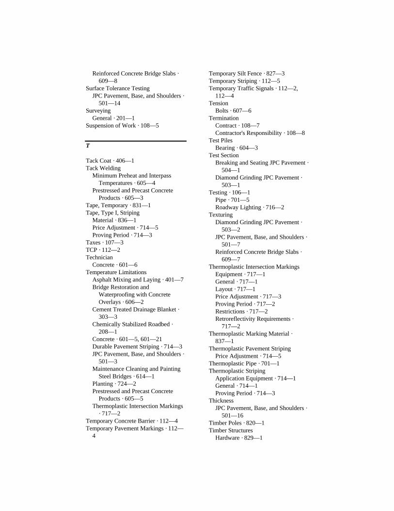
Reinforced Concrete Bridge Slabs ·609—8
Surface Tolerance TestingJPC Pavement, Base, and Shoulders ·
501—14Surveying
General · 201—1Suspension of Work · 108—5
T
Tack Coat · 406—1Tack Welding
Minimum Preheat and InterpassTemperatures · 605—4
Prestressed and Precast ConcreteProducts · 605—3
Tape, Temporary · 831—1Tape, Type I, Striping
Material · 836—1Price Adjustment · 714—5Proving Period · 714—3
Taxes · 107—3TCP · 112—2Technician
Concrete · 601—6Temperature Limitations
Asphalt Mixing and Laying · 401—7Bridge Restoration and
Waterproofing with ConcreteOverlays · 606—2
Cement Treated Drainage Blanket ·303—3
Chemically Stabilized Roadbed ·208—1
Concrete · 601—5, 601—21Durable Pavement Striping · 714—3JPC Pavement, Base, and Shoulders ·
501—3Maintenance Cleaning and Painting
Steel Bridges · 614—1Planting · 724—2Prestressed and Precast Concrete
Products · 605—5Thermoplastic Intersection Markings
· 717—2Temporary Concrete Barrier · 112—4Temporary Pavement Markings · 112—
4
Temporary Silt Fence · 827—3Temporary Striping · 112—5Temporary Traffic Signals · 112—2,
112—4Tension
Bolts · 607—6Termination
Contract · 108—7Contractor's Responsibility · 108—8
Test PilesBearing · 604—3
Test SectionBreaking and Seating JPC Pavement ·
504—1Diamond Grinding JPC Pavement ·
503—1Testing · 106—1
Pipe · 701—5Roadway Lighting · 716—2
TexturingDiamond Grinding JPC Pavement ·
503—2JPC Pavement, Base, and Shoulders ·
501—7Reinforced Concrete Bridge Slabs ·
609—7Thermoplastic Intersection Markings
Equipment · 717—1General · 717—1Layout · 717—1Price Adjustment · 717—3Proving Period · 717—2Restrictions · 717—2Retroreflectivity Requirements ·
717—2Thermoplastic Marking Material ·
837—1Thermoplastic Pavement Striping
Price Adjustment · 714—5Thermoplastic Pipe · 701—1Thermoplastic Striping
Application Equipment · 714—1General · 714—1Proving Period · 714—3
ThicknessJPC Pavement, Base, and Shoulders ·
501—16Timber Poles · 820—1Timber Structures
Hardware · 829—1

Time Clock · 835—1Time Limits
Discharge of Concrete · 601—16TMA · 112—2Tolerances · 105—2. See also,
Appendix AAccuracy of Reamed and Drilled
Holes · 607—3Asphalt Materials · 806—14Asphalt Surface · 403—9Bearing Piles · 604—5DGA and CSB Base · 302—3Diamond Grinding JPC Pavement ·
503—2Edge Distance of Bolts · 607—3JPC Pavement · 501—14JPC Pavement, Thickness · 501—16Prestressed and Precast · 605—7Roadway and Drainage Excavation ·
204—4Subgrade · 207—1
Topdressing · 212—2Topdresssing · 108—6Topsoil · 212—1, 827—4
Furnish and Place · 212—1Spreading Stockpiled · 204—3,
212—1Traffic Control
Barrier Walls · 112—5Crash Cushions · 112—5Detour · 112—4Devices · 112—4Diversion · 112—4Drop-Offs · 112—3, 112—5Flashing Arrow Board · 112—4General · 112—4Lane Closure, Long Term · 112—4Signs · 112—4Temporary Pavement Marking ·
112—5Temporary Traffic Signals · 112—4Traffic Control Coordinator · 112—6Traffic Control Plan · 112—2
Traffic Control Coordinator · 112—6Traffic Control Devices
Documentation · 836—4Equipment testing · 835—1General · 835—1
Pedestrian Pushbutton Detectors ·835—1
Pedestrian Signals · 835—3Signal Heads · 835—3Signals and Beacons · 835—2Temporary Traffic Signals · 112—2Time Clock · 835—1TMA · 112—2Traffic Loop Encapsulant · 835—3Warranties · 836—4
Traffic Loop Encapsulant · 835—3Traffic Signs, Panel
Beams and Supports · 715—2Bridge Mounting · 715—3Footings, Bases, and Pedestals ·
715—2General · 715—1Locating · 715—1Mounting, General · 715—3Shop Drawings · 715—2
Transformers · 834—3Transverse Construction Joints
JPC Pavement · 501—11Transverse Contraction Joints
JPC Pavement · 501—11Transverse Expansion Joints
JPC Pavement · 501—10Transverse Joints
Medians, Concrete · 507—1Treatment of Open Sinkholes · 215—1Trees · See PlantingTrees and Stumps
Removal · 202—1Tremies · 601—18, 601—19Trip Tickets
Concrete · 601—6Truck Mounted Attenuator · 112—2Tunnel Lining Materials · 819—1
Bolts and Nuts · 819—1Steel Plates · 819—1
Tunnels · 707—1
U
Under Water ConcretePlacing · 601—19
UndercuttingFoundation · 603—4Pipe · 701—7
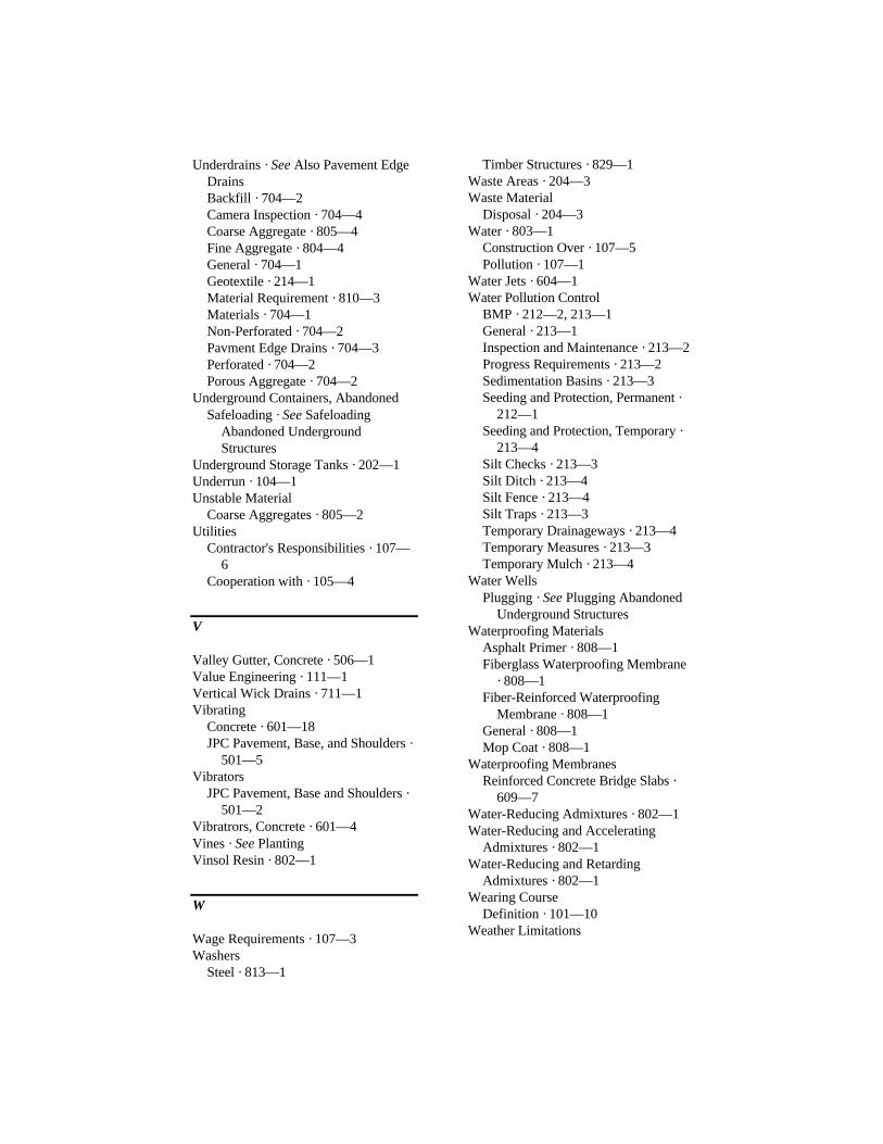
Underdrains · See Also Pavement EdgeDrainsBackfill · 704—2Camera Inspection · 704—4Coarse Aggregate · 805—4Fine Aggregate · 804—4General · 704—1Geotextile · 214—1Material Requirement · 810—3Materials · 704—1Non-Perforated · 704—2Pavment Edge Drains · 704—3Perforated · 704—2Porous Aggregate · 704—2
Underground Containers, AbandonedSafeloading · See Safeloading
Abandoned UndergroundStructures
Underground Storage Tanks · 202—1Underrun · 104—1Unstable Material
Coarse Aggregates · 805—2Utilities
Contractor's Responsibilities · 107—6
Cooperation with · 105—4
V
Valley Gutter, Concrete · 506—1Value Engineering · 111—1Vertical Wick Drains · 711—1Vibrating
Concrete · 601—18JPC Pavement, Base, and Shoulders ·
501—5Vibrators
JPC Pavement, Base and Shoulders ·501—2
Vibratrors, Concrete · 601—4Vines · See PlantingVinsol Resin · 802—1
W
Wage Requirements · 107—3Washers
Steel · 813—1
Timber Structures · 829—1Waste Areas · 204—3Waste Material
Disposal · 204—3Water · 803—1
Construction Over · 107—5Pollution · 107—1
Water Jets · 604—1Water Pollution Control
BMP · 212—2, 213—1General · 213—1Inspection and Maintenance · 213—2Progress Requirements · 213—2Sedimentation Basins · 213—3Seeding and Protection, Permanent ·
212—1Seeding and Protection, Temporary ·
213—4Silt Checks · 213—3Silt Ditch · 213—4Silt Fence · 213—4Silt Traps · 213—3Temporary Drainageways · 213—4Temporary Measures · 213—3Temporary Mulch · 213—4
Water WellsPlugging · See Plugging Abandoned
Underground StructuresWaterproofing Materials
Asphalt Primer · 808—1Fiberglass Waterproofing Membrane
· 808—1Fiber-Reinforced Waterproofing
Membrane · 808—1General · 808—1Mop Coat · 808—1
Waterproofing MembranesReinforced Concrete Bridge Slabs ·
609—7Water-Reducing Admixtures · 802—1Water-Reducing and Accelerating
Admixtures · 802—1Water-Reducing and Retarding
Admixtures · 802—1Wearing Course
Definition · 101—10Weather Limitations

Bridge Restoration andWaterproofing with ConcreteOverlays · 606—2
Cement Treated Drainage Blanket ·303—3
Chemically Stabilized Roadbed ·208—1
Concrete · 601—21Durable Pavement Striping · 714—3JPC Pavement, Base, and Shoulders ·
501—3Maintenance Cleaning and Painting
Steel Bridges · 614—1Planting · 724—2Prestressed Concrete Products ·
605—5Reinforced Concrete Bridge Slabs ·
609—5Thermoplastic Intersection Markings
· 717—2Web Plates
Structural Steel Bridges · 607—11Weep Holes
Box Culverts · 611—2Concrete Slope Walls · 703—1Retaining Walls · 613—2
Weighing · 109—2Small Quantities · 109—6
Weight Limits · 105—6, 105—7Welded Deformed Steel Wire Fabric ·
811—1Welded Steel Wire Fabric (WWF) ·
602—3Material Requirements · 811—1
WeldingCertification · 106—3Materials, Procedures, and Inspection
· 813—5Procedures for Structural Steel
Bridges · 607—2Structual Steel Bridges · 607—9Tack · 605—3
WellsFilling and Capping · See Filling and
Capping AbandondedUnderground Structures
Wells (Water)Plugging · See Plugging Abandoned
Underground StructuresWet Curing Concrete · 601—30White Polyethylene Film · 823—1Wick Drains · 711—1Wiring
Roadway Lighting · 716—1Splicing · 716—2
Wood ProductsBoards · 818—1Bridge Planking and Rough Local
Hardwoods · 818—1Dimension Lumber · 818—1General · 818—1Inspection, Testing, and Acceptance ·
818—1Preservative Treatment · 818—2Structural Lumber · 818—1Timbers, 5-inch by 5-inch and larger ·
818—1Work
Contractor's Responsibility · 107—6Definition · 101—13Failure to Complete on Time · 108—
6Force Account · 109—7Prosecution of · 108—2Suspension of · 108—5Through National Forests and Parks ·
107—2Working Days · 108—2, 108—3
Definition · 101—13Working Drawings · 105—2
Definition · 101—14Woven Wire Fabric, Material
Requirements · 816—1Woven Wire Fencing Material
Barbed Wire · 816—1Brace Wire · 816—1Braces · 816—1Fabric Ties · 816—1Gates · 816—2General · 816—1Posts · 816—1Woven Wire Fabric · 816—1

APPENDIX C
ENGLISH – METRICCONVERSION TABLE

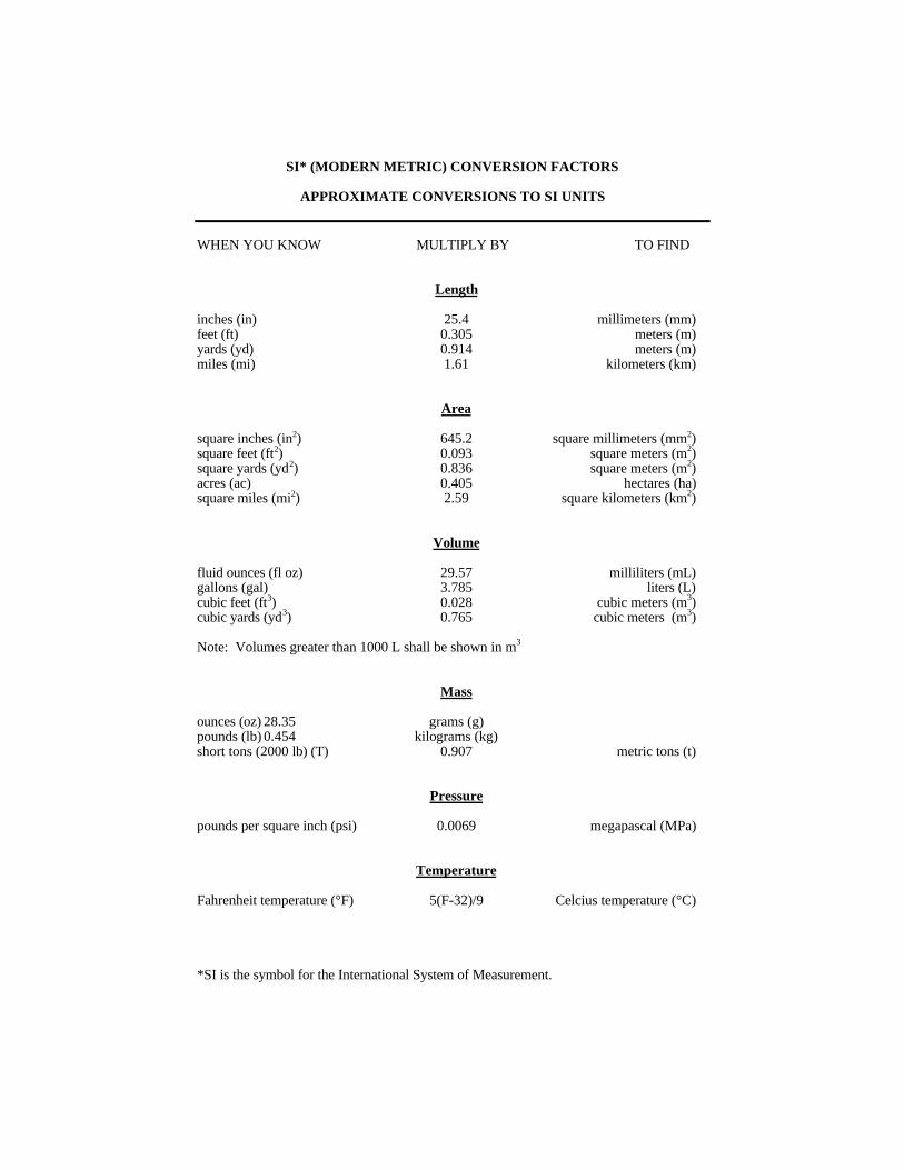
SI* (MODERN METRIC) CONVERSION FACTORS
APPROXIMATE CONVERSIONS TO SI UNITS
WHEN YOU KNOW MULTIPLY BY TO FIND
Length
inches (in) 25.4 millimeters (mm)feet (ft) 0.305 meters (m)yards (yd) 0.914 meters (m)miles (mi) 1.61 kilometers (km)
Area
square inches (in2) 645.2 square millimeters (mm2)square feet (ft2) 0.093 square meters (m2)square yards (yd2) 0.836 square meters (m2)acres (ac) 0.405 hectares (ha)square miles (mi2) 2.59 square kilometers (km2)
Volume
fluid ounces (fl oz) 29.57 milliliters (mL)gallons (gal) 3.785 liters (L)cubic feet (ft3) 0.028 cubic meters (m3)cubic yards (yd3) 0.765 cubic meters (m3)
Note: Volumes greater than 1000 L shall be shown in m3
Mass
ounces (oz) 28.35 grams (g)pounds (lb) 0.454 kilograms (kg)short tons (2000 lb) (T) 0.907 metric tons (t)
Pressure
pounds per square inch (psi) 0.0069 megapascal (MPa)
Temperature
Fahrenheit temperature (°F) 5(F-32)/9 Celcius temperature (°C)
*SI is the symbol for the International System of Measurement.

SI* (MODERN METRIC) CONVERSION FACTORS
APPROXIMATE CONVERSIONS FROM SI UNITS
WHEN YOU KNOW MULTIPLY BY TO FIND
Length
millimeters (mm) 0.039 inches (in)meters (m) 3.28 feet (ft)meters (m) 1.09 yards (yd)kilometers (km) 0.621 miles (mi)
Area
square millimeters (mm2) 0.0016 square inches (in2)square meters (m2) 10.764 square feet (ft2)hectacres (ha) 2.47 acres (ac)square kilometers (km2) 0.386 square miles (mi2)
Volume
milliliters (mL) 0.034 fluid ounces (fl oz)liters (L) 0.264 gallons (gal)cubic meters (m3) 35.315 cubic feet (ft3)cubic meters (m3) 1.308 cubic yards (yd3)
Mass
grams (g) 0.035 ounces (oz)kilograms (kg) 2.205 pounds (lb)metric tons (t) 1.102 short tons (2000) (T)
Pressure
megapascals (MPa) 145.04 pounds per square inch (psi)
Temperature
Celcius temperature (°C) 1.8C + 32 Fahrenheit temperature (°F)