standard specifications and design...
TRANSCRIPT


5204 5204.1 5204.2 5204.3 5204.4 5204.5 5204.6 5204.7 5204.8 5204.9 5204.10 5204.11 5204.12 5204.13
5205 FIGURES
5206
GENERAL PLAN REQUIREMENTS scope ...................................... General ..................................... Scales ...................................... Sheet Sixes ................................... TypesofSheetsinPlans .......................... Required Information for Title Sheet .................. Required Information for General Layout Sheet ........... Required Information for Planed and Profile Sheets ......... Required Information for Cross-Section Sheets ............ Required Information for Standard and Special Detail Sheets ... Required Information for Lighting Plans ................ Required Information for Traffic Control Plan Sheets ........ Required Information for Temp. Erosion Control Plan Sheets ...
.................. 52-8
.................. 52-8
.................. 52-8
.................. 52-8
.................. 52-8
.................. 52-9
.................. 52-9
.................. 52-9
................. 52-10
................. 52-l 1
................. 52-l 1
................. 52-11
................. 52-l 1
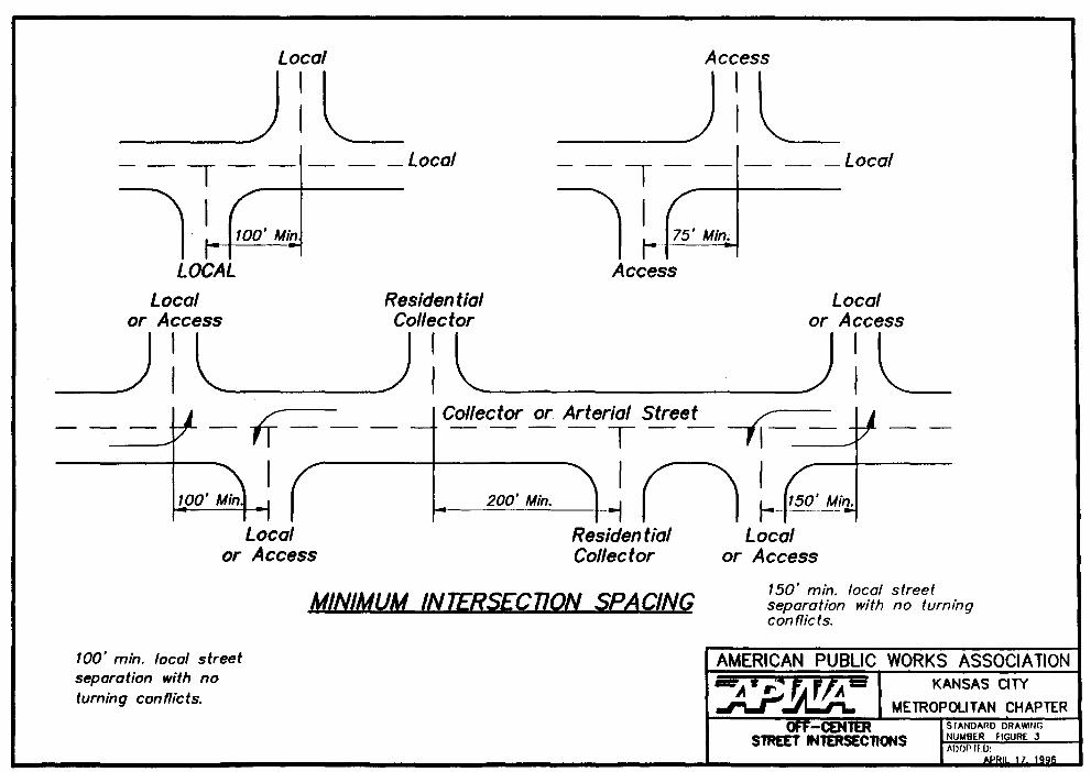
FIGURE 1 - Design Controls for Sag Vertical Curves ......................... 52- 12 FIGURE 2 - Design Controls for Crest Vertical Curves ........................ 52-13 FIGURE 3 - Off-Center Street Intersections ................................ 52-14 FIGURE 4 - Typical Residential Street Layout .............................. 52-15 FIGURE SMB - Survey Monument Box .................................. 52-16
TABLES TABLE 1 -Street Pavement Types . . . . . . . . . . . . . . . . . . . . . . . . . . . . . . . . . . . 52-17


5201.4 Governing Specifications: Design shall be in accordance with the latest edition of the following specifications and the current interim supplements thereto except as modified herein or modified for the specific project:
A. Ay on Gek, AASHTO.
R. Con FHWA.
C. vDesirm AASHTO.
D. Designof Pavs, AASHTO.
SECTION 5202 FUNCTIONAL CLASSIFICATION OF STREETS:
5202.1
5202.2
5202.3
5202.4
5202.5
5202.6
Major Arterial Streets (or Primary Arterial, or Urban Principal Arterial): Streets that serve the highest trafftc volume corridors and the longest trip. Provides travel between business districts and outlying residential areas, between major inner city communities and between major suburban centers, and connects communities to major state and interstate highways. No or limited access is allowed from residential streets. Access is usually partially controlled. Spacing of major arterial streets is generally from one mile to five miles.
Minor Arterial Streets (or Secondary Arterial, or Urban Minor Arterial): Streets that interconnect and augment the major arterial streets. No or limited access is allowed from residential lots. Accommodate trips of moderate length at a lower level of travel mobility than major arterial streets. Spacing of minor arterial streets is generally from one-half mile to three miles.
Industrial/Commercial Cokctor (or Collector, or Urban Collector): Streets that collect traffic to and from commercial or industrial areas and distribute it to arterial streets.
Residential Collector Streets (or Collector, or Urban Collector): Streets that collect traffic to and from residential areas and distribute it to arterial streets. Limited access is allowed from residential lots. Desirable maximum ADT = 3,000 for residential collector streets.
Residential Local Streets (or Local, or Urban Local): Streets that only carry traffic having its origin or destination within the immediate neighborhood. Desirable maximum ADT = 1.000 for local streets. (ADT = ten trips per day per typical single-family residence. )
Residential Access Streets: Streets that carry traffic between residential lots and residential local streets or residential collector streets. Residential access streets usually carry no through traffic and include short loop streets, cul-de-sacs, and courts. Desirable maximum ADT = 200 for cul-de-sacs and 400 for loop streets. Maximum length of cul-de-sacs = 500 feet and 1.000 feet for loop streets. (ADT = ten trips per day per typical single-family residence.)
SECTION 5203 GENERAL STREET DESIGN CRITERIA:
5203.1 Design Criteria: This section governs the general design requirements for the following street classifications (see notes on page 52-4):
52-2


ep 0 2
N N
8 .- 2 i= b s E E’ .- .- 5
E M
z


5203.2
5203.3
5203.4
5203.5
5203.6
5203.7
5203.8
5203.9
5203.10
5203.11
5203.12
5203.13
Maximum and Minimum Gradient: The maximum and minimum gradient for streets as noted in Section 5203.1 may be exceeded only upon written approval of the local governing agency.
Shoulder Gradients: The finished grade within the limits of the right-of-way shall slope from 2% one-quarter (l/4) inch vertical to one (1) foot horizontal minimum. to 4% one-half ( l/2) inch vertical to one (1) foot horizontal maximum measured above the back of the curb. The grading gradients may be varied only upon written approval of the local governing agency. Back slopes beyond the R/W line shall be 3: 1 maximum, 4: 1 desirable.
Tangent Length: No tangent length shall be required between reverse curves for residential access and local streets. The minimum tangent length between reverse curves shall be 100 feet for collector/industrial streets. Major and minor arterial streets shall comply with current AASHTO guidelines.
Off-Center Street Intersections: Off-center street intersections shall be separated as shown on Figure 3(M).
Intersection Angle: It is desirable for all intersections to meet at approximately a 90” angle. Skewed intersections should be avoided and in no case should the angle be less than 75’.
Intersecting Minor/Major Arterial Streets: Where any minor or major arterial streets intersect each other, the crowns of both streets shall be uniformly transitioned into a plane at the intersection unless otherwise approved. Changes from one cross slope to another should be gradual.
Curb Radii: When two streets of different classification intersect. the higher classification street shall govern the curb radii dimension listed in 5203.1. Equivalent three-center compound curves may be used in lieu of a single radius curve. Curb ends facing the flow of traffic shall have a five-foot taper from full height to zero.
Sight Distance at Intersecting Streets: Sight distance triangles at intersecting side streets shall be in accordance with the current edition of Av on -Design of Highways and Streets. AASHTO. Every effort shall be made to select intersection locations so that the maximum sight distance is possible.
Considerations For Connection to Existing and Future Streets: Consideration shall be given to the horizontal and vertical alignment of roadways where they connect to existing streets or where roadways may be extended in the future. Where a new street is to connect to an existing street, all deteriorated or cracked asphalt within five feet of the connection point shall be removed to a point where sound material is found. Existing pavement is to be saw cut for the entire width of the street to a minimum depth of six inches. If full-depth pavement removal is required. the subgrade shall be re-compacted to 95% of standard density.
Pavement Section: Pavement shall be constructed upon compacted subgrade and of materials and the minimum thickness as shown on the standard drawings for the applicable street classification.
Pavement Transition: Reduction in pavement width in the direction of traffic flow shall be accomplished by a taper. The minimum desirable length for merging taper shall be determined by the formula L=Ws?/60 where posted speeds are 45 mph or less. The formula L= WxS should be used for roadways having a posted speed limit greater than 45 mph. Under either formula, L= taper length in feet, W = width of the closed lane in feet, and S = design speed. in mph.
Cul-De-Sacs: At locations where streets are to be terminated and a vehicular connection between adjacent streets is not required, the termination shall be a cul-de-sac. Such cul-de-sac shall be
52-6

constructed with a minimum radius of 39 feet to the back of the curb if there are no islands located in the cul-de-sac.
5203.14 Temporary Turn-Arounds: At locations where streets will be temporarily terminated and which will be extended at a later date, and said street extends beyond the intersection of an adjacent street more than 150 feet, a temporary cul-de-sac shall be constructed with a minimum radius of thirty-five (35) feet. The temporary cul-de-sac shall be constructed of asphaltic concrete with a minimum depth of eight inches. Curb and gutter will not be required. The cul-de-sac shall be constructed within the limits of a temporary easement.
Temporary Turn-Arounds shall be located so that they do not interfere with permanent development They should normally be located on property adjacent to the property to be served. For new subdivision plats, they should be located on property beyond the limits of the plat.
5203.15 Driveway Grades: Driveway grades shall conform to the typical section of the street within the right of way. Any deviations shall be approved by the local government official with the following limitations: Driveways shall attain a minimum elevation of six inches above the gutter elevation within the right of way with a maximum grade of 8 % . The algebraic difference in grades at the right-of-way on crest drives shall be 8% maximum and on sag drives shall be 12% maximum. The maximum driveway grade outside the right-of-way shall be 15 % .
5203.16 Access for the Disabled: Ramps shall be required at all planned sidewalk-curb intersections in accordance with standard practice and approved by the local governing agency. Non-standard driveways and alleys will also be designed to accommodate the handicapped.
5203.17 Street Lighting: All street lighting shall be designed in accordance with Section 5800 of the APWA design criteria unless otherwise directed or approved by the local governing agency.
5203.18 Storm Drainage: All storm drainage shall be designed in accordance with Section 5600 of the APWA design criteria unless otherwise directed or approved by the local governing agency.
5203.19 Underdrains: In areas that have known subsurface moisture problems. underdrains or drainage blankets shall be designed.
5203.20 Erosion Control Within R/W Limits: As a minimum, all grass areas in the R/W shall be seeded and mulched to control erosion on to the roadway. All construction prqjects that have exposed grading require temporary erosion control measures. Temporary erosion control must be approved by the City Engineer.
5203.21 Survey Monument Boxes: Monument boxes conforming to Figure 5 shall be installed at all quarter section comers involved in the street construction. The monument boxes shall be set by a Registered Land Surveyor licensed in the state the monumentation work is performed.
5203.22 Traffic Impact Studies: Required where developments have adverse impact on existing traffic conditions.
5203.23 Obstructions: Rigid structures such as poles and hydrants shall be placed a.minimum horizontal distance of 1.5 feet from the face of curb to edge of obstruction. When required, guardrail and barricades shall be installed in accordance with the AASHTO Roadside Design Guide or local policies. Vertical clearance of a minimum 14.5 feet shall be provided. Along sidewalks, a minimum vertical clearance of seven feet shall be provided.
a 5203.24 Other Design Criteria: Design criteria not covered by this document shall be in accordance with the most current edition of APalicy on m of Highways and Streets by the American
52-7

Association of State Highway and Transportation Officials (AASHTO) or other applicable AASHTO design guides.
SECTION 5204 GENERAL PLAN REQUIREMENTS:
5204.1 Scope: This section governs the preparation of plans for street prqjects.
5204.2 General: The plans shall include all information necessary to build and check the design of streets and related appurtenances. The plans shall be arranged as required by the City Engineer of local governing agency. Applicable standard plans of the local governing agency may be included by reference to standard plan number and title. Plans shall be sealed by a Registered Professional Engineer in the state of the city or governing agency and shah be submitted to the local governing agency for review and approval.
5204.3 Scales: Plans shall be drawn at the following minimum scales. Larger scales may be needed to clearly present the design. Bar scales shall be shown on each sheet for each scale.
Plan: 1 inch = 50 feet Suburban 1 inch = 20 feet Urban
Profile: Vertical:
Horizontal:
1 inch = 10 feet Suburban 1 inch = 5 feet Urban 1 inch = 50 feet Suburban 1 inch = 20 feet Urban
Drainage Area Map: On site: Off site:
1 inch = 200 feet 1 inch = 1,000 feet
Structural Plans: 1 inch = 1 foot
Graphic Drawings: Varies
5204.4 Sheet Sizes: The suggested plan sheet size is 22 inches x 36 inches, 23 inches x 34 inches. or 24 inches x 36 inches with all sheets in a given set of plans being of the same size. Plan and profile shall be drawn on combined or separate plan and profile sheets to minimum scales shown above.
5204.5 Types of Sheets in Plans: The plans shall consist of:
1. Title sheet 2. General layout sheets 3. Plan and profile sheets 4. Cross-section sheets 5. Drainage area map 6. Standard and special detail sheets 7. Lighting plans (if required) 8. Traffic control plans (if required) 9. Temporary erosion control plans (if required)
Each sheet should contain a sheet number, including the individual sheet number and the total number of sheets, proper project identification and date. Where feasible, storm sewer construction details should be incorporated into the street plans. The engineer’s seal shall appear on the title sheet.
52-8

5204.6 Required Information for Title Sheet:
1. Name of project.
2.
3.
4.
5. Signature block for local governing agency approval.
6. The project control bench marks shah be identified as to location and elevation: NGVD datum or as required by the local governing agency. A minimum of two (2) bench marks are required for any project.
7.
8.
9.
10.
11.
Project number (where applicable).
Index of sheets included in plans.
A location map adequately showing project location in relation to major streets. with north arrow and scale.
Name, address and telephone number of the consulting engineer and owner/developer as well as signature block for the owner/developer.
List containing name and telephone number of each utility company and the State One-Call System.
A legend of symbols shah be shown that shah apply to all sheets.
Design speed plus other traffic information as required by the local governing agency.
Engineer’s seal, signed and &ted.
5204.7 Required Information for General Layout Sheet:
1. General Notes: Minor construction notes shah appear on the proper plan and profile sheet.
2. North arrow and bar scale. Scale of the general layout map shall be one ( 1) inch equals one hundred ( 100) feet.
3. Layout shah include name of subdivision, block designation if any. lot designation or proposed block and lots, all street names, street alignment with back of curb lines. and an accurate tie to at least one quarter section comer. An unplatted tract shall have an accurate tie to at least two (2) quarter section comers.
4. Boundary line of project area.
5. Schematic layout of all proposed sidewalks and utility improvements including storm drainage. sanitary sewers, water lines, street lights, traffic signals, etc., shall be shown.
6. A list of materials and quantities if not provided on a separate sheet.
7. Typical street sections and curb and gutter details.
5204.8 Required Information for Plan and Profile Sheets:
1. North arrows and bar scale.
52-9

3 -.
3.
4.
5.
6.
7.
8.
9.
10.
11.
12.
13.
14.
15.
16.
Elevation and location of all applicable benchmarks; NGVD datum or as required by the local governing agency.
Existing and proposed streets with names and pavement widths.
Property lines properly identified as to existing or proposed lot. block and subdivision. Survey base line with adequate ties to land lines.
All existing and proposed utilities such as power, gas. oil. water. telephone. sewer. and other items shall be properly located in conformance with the best information available in the records of the owner of such facilities, or field location. and identified as to size and material.
All existing and known proposed improvements within 50 feet each side of right-of-way and 200 feet beyond the project limits shall be shown at their proper locations unless otherwise approved or required by the local governing agency. This shah include such existing items as paved streets, curb and gutters, driveways, culverts. fire hydrants. utility poles. trees. shrubs. fences, walls, houses, and other such items, and shall be identified as to type. size, material. etc. as may be applicable.
All existing and proposed easements and right-of-way information.
Locations and widths of existing and proposed sidewalks.
Horizontal curve data and vertical curve data (K value, stopping sight distance. and middle ordinate).
Center line stations shall be marked at lOO-foot intervals and at other pertinent points.
Top of curb elevations shall be shown at maximum increments of 15 feet along the curb returns at street intersections.
Profile shall show existing grade as a dashed line, proposed finish grades or established street grades by solid lines.
Storm sewer criteria shall be in accordance with Section V.
Elevations shah be shown at a minimum interval of 50 feet for tangents and 25 feet for curves.
Approximate grading limits.
Location of test borings if taken.
5204.9 Required Information for Cross-Section Sheets:
1. Street cross section at each station showing existing grade by dashed lines and proposed grade by a solid line. Cross sections to show existing grade lines a minimum of ten (10) feet beyond right-of-way lines or grading limit, whichever is further. The center line and location right- of-way shah be shown.
2.
3.
4.
Center line elevation of top of pavement.
Center line cross sections shall be shown at all intersecting streets and driveways.
Additional cross sections shah be shown as required to clearly describe the extent of the grading operations.
52-10

5. In lieu of cross sections for residential development. three or five line profiles may be used if approved by the local governing agency. The three line profiles shall consisr of a profile of the existing grotmd at each right-of-way line and existing and finished profile at the center line of the street. The other two profiles shall show the fina grade at the building setback line. A grading plan may be required for residential development.
5204.10 Required Information for Standard and Special Detail Sheets: Detail sheets shall be included to show all details of appurtenances, materials, and construction. Details shall conform ro the requirements of the local governing agency and are to be drawn clearly and neatly with proper identifications, dimensions, materials and other information necessary to insure the desired construction.
5204.11 Required Information for Liiting Plans: Street lighting plans shall be prepared in accordance with Section 5800 of the APWA design criteria and included in addition to the street improvement plans for approval. The plan shah be at 1 inch = 50 feet (minimum) scale with the streets and adjacent plats labeled.
5204.12 Required Information for Traffic Control Plan Sheets:
1. Limits of any road closures shall be shown along with the traffic control devices used to effect the closure. Length of time of road closure shall be indicated.
2. Detour plan shall be desiwd for traffic affected by road closures. Detour signing used to direct motorist over the detour route shall be included in the detour plan.
3. Typical lane closure or lane shift plans including taper lengths and spacing of all ChaMeliZer
devices. Types and spacing of all construction ;igns shah be shown.
4. All traffic control shall be designed using the traffic control devices and application principles contained in the MUTCD.
5204.13 Required Information for Temporary Erosion Control Plan Sheets:
1. Each temporary erosion control feature designation shall be shown at its proper location on the pla.tK
2. Temporary erosion control devices details as required. such as standard temporary beams, temporary slope drains, types of ditch checks. and sediment basins.
52-11

SECTION 5205 FIGURES
L - MINIMUM LENGTH OF SAG VERTICAL CURVE IFT)
DESGN CONTROLS FOR SAG VERTICAL CURVES OPEN ROAD CONDITIONS
UPPER RANGE
source: 1990 AASHTO . . . . A Pohv on Gsmmx D-w of Huibwys and streets

l .
DESIGN CONTROLS FOR CREST VERTICAL CURVES M)R STOPPING SIGHT DISTANCE AND OPEN ROAD CONDITIONS
UPPER RANGE

ART2ERlAL STREET
Z Access Street
m Local Street
Collector Street
ICAL RESIDEN77AL S7REET LAYOUT
AMERICAN PUBL _ -,IC WORKS ASSOCIATION KANSAS CITY
MElROPOUTAN CHAPTER I STAUnAPn nR.YUE - . . . . _-_...- -..- . . . . . -
mkTGM NUMBER FIGURE 4 ADOPTED:
APRII 17. 1996

cost Iron vohe Box Uorkcd ‘SUMW’ an /--
Asphalt or Concrete (In Pond Amos)
Lid, Cloy k key No. 2194 or Approved Equal.
JO’ Standard Aluminum Pipe Monument with Magnetic Cap bumsten Type A130 or Apprausd Equal Set Monument so that the Cop con be Read from the South.
Cost-In-Place Concrete
Compacted Moist soil 8odff7ll
Cost-In-Place Concrete
-
Undisturbed Subgmde
/ (No Scale)
Note: Disk marking for section corners shall comply with Missouri DNR land Survey Division Standards of Practice lOCSR30-3.060 for monument markings in Missouri and with Kansas Society of Land Surwprs Standords of Practice #‘I for monuments in Kansas.
AMERICAN PUBLIC WORKS ASSOClATlON
-5JpQ= KANSAS CITY
METROPOLITAN CHAPTER SURIlEY STANDARD DRAWNG
MoNUMENf Box NUMBER FIGURE SMB

P e f