standard requirements for analysis of shallow concrete ... · concrete foundations ... design of...
TRANSCRIPT
Standard Requirements
for Analysis of Shallow
Concrete Foundations
on Expansive Soils
8601 N. Black Canyon HighwaySuite 103Phoenix, Arizona 85021
Telephone: (602) 870-7540Fax: (602) 870-7541Website: www.post-tensioning.org
May 2008

Copyright © 2004, 2006, 2007, 2008
By the Post-Tensioning Institute
4th Edition, First Printing
May 2008
Printed in the U.S.A.
All rights reserved. This book or any part thereof may notbe reproduced in any form without the written permissionof the Post-Tensioning Institute.
This publication is intended for the use of professionals competent to evaluate the significance and limitations of its contents and who willaccept responsibility for the application of the materials it contains. The Post-Tensioning Institute in publishing this document makes nowarranty regarding the recommendations contained herein, including warranties of quality, worksmanship or safety, express or implied, fur-ther including, but not limited to, implied warranties or merchantability and fitness for a particular purpose.
THE POST-TENSIONING INSTITUTE SHALL NOT BE LIABLE FOR ANY DAMAGES, INCLUDING CONSEQUENTIAL DAMAGES,BEYOND REFUND OF THE PURCHASE PRICE OF THIS PUBLICATION.
The incorporation by reference or quotation of material in this publication in any specifications, contract documents, purchase orders, draw-ings or job details shall be done at the risk of those making such reference or quotation and shall not subject the Post-Tensioning Institute toany liability, direct or indirect, and those making such reference or quotation shall waive any claims against the Post-Tensioning Institute.
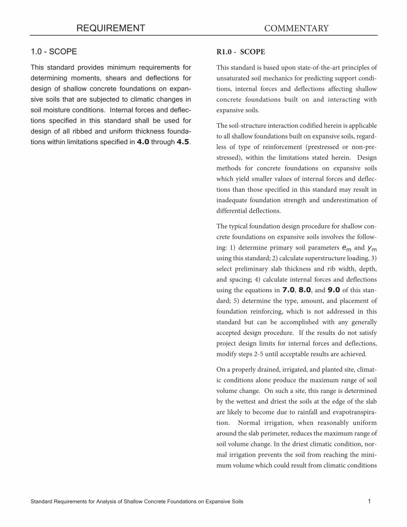
1.0 - SCOPE
This standard provides minimum requirements for
determining moments, shears and deflections for
design of shallow concrete foundations on expan-
sive soils that are subjected to climatic changes in
soil moisture conditions. Internal forces and deflec-
tions specified in this standard shall be used for
design of all ribbed and uniform thickness founda-
tions within limitations specified in 4.0 through 4.5.
REQUIREMENT
Standard Requirements for Analysis of Shallow Concrete Foundations on Expansive Soils 1
R1.0 - SCOPE
This standard is based upon state-of-the-art principles ofunsaturated soil mechanics for predicting support condi-tions, internal forces and deflections affecting shallowconcrete foundations built on and interacting withexpansive soils.
The soil-structure interaction codified herein is applicableto all shallow foundations built on expansive soils, regard-less of type of reinforcement (prestressed or non-pre-stressed), within the limitations stated herein. Designmethods for concrete foundations on expansive soilswhich yield smaller values of internal forces and deflec-tions than those specified in this standard may result ininadequate foundation strength and underestimation ofdifferential deflections.
The typical foundation design procedure for shallow con-crete foundations on expansive soils involves the follow-ing: 1) determine primary soil parameters em and ym
using this standard; 2) calculate superstructure loading, 3)select preliminary slab thickness and rib width, depth,and spacing; 4) calculate internal forces and deflectionsusing the equations in 7.0, 8.0, and 9.0 of this stan-dard; 5) determine the type, amount, and placement offoundation reinforcing, which is not addressed in thisstandard but can be accomplished with any generallyaccepted design procedure. If the results do not satisfyproject design limits for internal forces and deflections,modify steps 2-5 until acceptable results are achieved.
On a properly drained, irrigated, and planted site, climat-ic conditions alone produce the maximum range of soilvolume change. On such a site, this range is determinedby the wettest and driest the soils at the edge of the slabare likely to become due to rainfall and evapotranspira-tion. Normal irrigation, when reasonably uniformaround the slab perimeter, reduces the maximum range ofsoil volume change. In the driest climatic condition, nor-mal irrigation prevents the soil from reaching the mini-mum volume which could result from climatic conditions
COMMENTARY
1.1 This standard is based upon "Design of Post-
Tensioned Slabs-on-Ground", 3rd Edition, Post-
Tensioning Institute, Phoenix, Arizona, 2004,
Addendum No. 1, May 2007 and Addendum No. 2,
May 2008. The user is referred to those documents
and the commentary to this standard for background
and interpretational information which clarify its
application.
2 Standard Requirements for Analysis of Shallow Concrete Foundations on Expansive Soils
alone. In the wettest condition, irrigation is not normallyused; therefore, it does not affect the maximum soil vol-ume which results from climatic conditions alone. Designof foundations on an unusually wet or dry soil (due todrought or extended rainfall) may require considerationof soil profiles with extreme swell or shrink movements.
REQUIREMENT COMMENTARY

psi
Ecr = Long-term or creep modulus of elasticity of
concrete, psi. May be taken as one-half of Ec
Est = Modulus of elasticity of non-prestressed rein-
forcement, psi
em = Edge moisture variation distance, distance
measured inward from slab edge in which
soil moisture content varies, ft
e = Base of natural (Naperian) logarithms
fc = Fine clay
f'c = Specified compressive strength of concrete, psi
Ff = Fabric factor used to modify unsaturated dif-
fusion coefficient (α) for presence of roots,
layers, fractures, and joints (See Table 1).
h = Total depth of rib, measured from top surface
of slab to bottom of rib, in.
H = Thickness of a uniform thickness foundation, in.
I = Gross moment of inertia of cross-section, in4
Ie = Moment of inertia of transformed (cracked)
cross-section using Est/Ec = 10
Im = Thornthwaite Moisture Index
L = Total slab length (or total length of design
rectangle) in direction being considered
(short or long), perpendicular to W, ft
LL = Long dimension of design rectangle, ft
LS = Short dimension of design rectangle, ft
Standard Requirements for Analysis of Shallow Concrete Foundations on Expansive Soils 3
33 1.5w fc'Ec = Modulus of elasticity of concrete =
2.0 - NOTATION AND ABBREVIATIONS
2.1 Notation
b = Rib width, in.
REQUIREMENT COMMENTARY
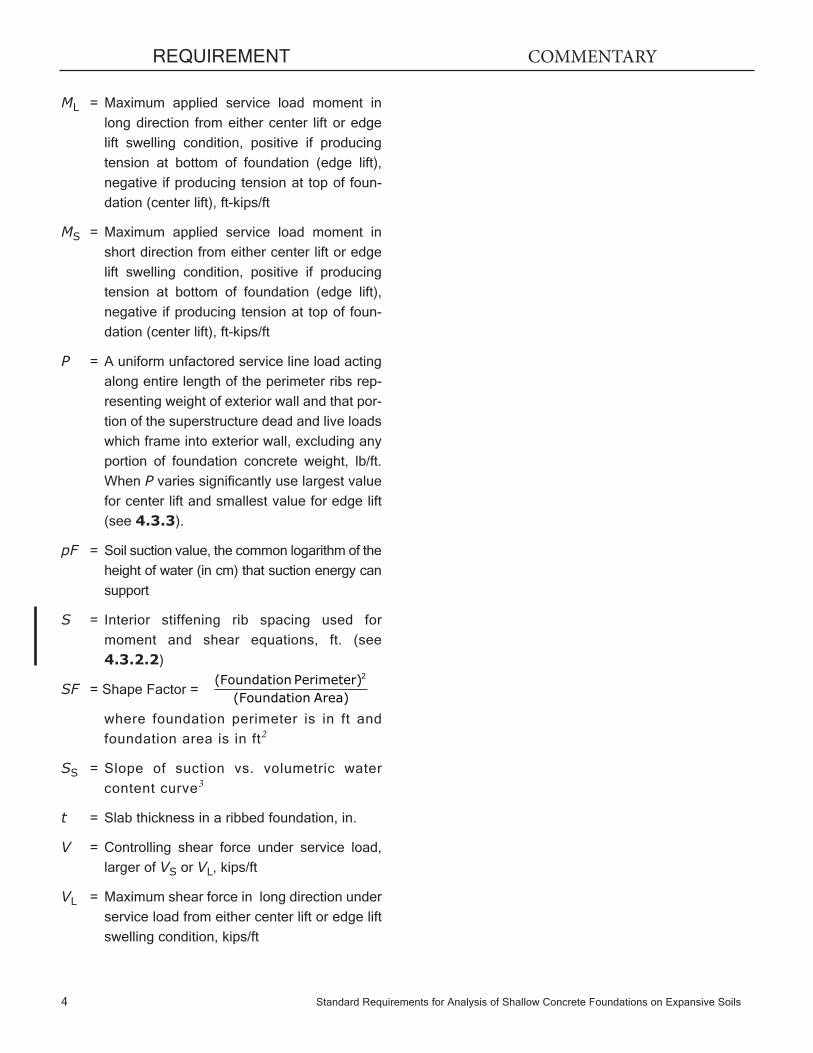
ML = Maximum applied service load moment in
long direction from either center lift or edge
lift swelling condition, positive if producing
tension at bottom of foundation (edge lift),
negative if producing tension at top of foun-
dation (center lift), ft-kips/ft
MS = Maximum applied service load moment in
short direction from either center lift or edge
lift swelling condition, positive if producing
tension at bottom of foundation (edge lift),
negative if producing tension at top of foun-
dation (center lift), ft-kips/ft
P = A uniform unfactored service line load acting
along entire length of the perimeter ribs rep-
resenting weight of exterior wall and that por-
tion of the superstructure dead and live loads
which frame into exterior wall, excluding any
portion of foundation concrete weight, lb/ft.
When P varies significantly use largest value
for center lift and smallest value for edge lift
(see 4.3.3).
pF = Soil suction value, the common logarithm of the
height of water (in cm) that suction energy can
support
S = Interior stiffening rib spacing used for
moment and shear equations, ft. (see
4.3.2.2)
SF = Shape Factor =
where foundation perimeter is in ft and
foundation area is in ft2
SS = Slope of suction vs. volumetric water
content curve3
t = Slab thickness in a ribbed foundation, in.
V = Controlling shear force under service load,
larger of VS or VL, kips/ft
VL = Maximum shear force in long direction under
service load from either center lift or edge lift
swelling condition, kips/ft
4 Standard Requirements for Analysis of Shallow Concrete Foundations on Expansive Soils
(Foundation Perimeter)(Foundation Area)
2
REQUIREMENT COMMENTARY

VS = Maximum shear force in short direction
under service load from either center lift or
edge lift swelling condition, kips/ft
w = Unit weight of concrete, lb/ft3
W = Foundation width (or width of design rectan-
gle) in direction being considered (short or
long), perpendicular to L, ft
α = Unsaturated diffusion coefficient, a measure
of moisture movement in unsaturated soils
α' = Unsaturated diffusion coefficient modified by
soil fabric factor, α'= αFf
α'swell = α' value for edge lift swell condition
(swelling)
α'shrink = α' value for center lift swell condition
(shrinkage)
Δ0 = Expected differential deflection of foundation, in.
ym = Maximum unrestrained differential soil
movement, in.
ym swell = ym value for edge lift swell condition
(swelling), in.
ym shrink = ym value for center lift swell condition
(shrinkage), in.
zm = Depth below soil surface at which the suc-
tion varies by less than 0.027pF/ft
β = Approximate distance from edge of slab to
point of maximum moment and/or shear, a
function of the relative stiffness of the soil
and the foundation, ft
γ0 = Change of soil volume for a unit change in
suction for 100% fine clay
γ h = Change of soil volume for a unit change in
suction corrected for actual % fine clay.
Also referred to as matrix suction compres-
sion index
γ h mod = γ h weighted for layered soils
Standard Requirements for Analysis of Shallow Concrete Foundations on Expansive Soils 5
REQUIREMENT COMMENTARY
6 Standard Requirements for Analysis of Shallow Concrete Foundations on Expansive Soils
γ h mod swell = γ h mod value for edge lift swell
condition (swelling)
γ h mod shrink = γ h mod value for center lift swell
condition.(shrinkage)
2.1 Abbreviations
EI = Expansion Index
LL = Liquid Limit, %
PI = Plasticity Index
PL = Plastic Limit, %
SCF= Stress Change Factor, used in determination
of ym
3.0 - DEFINITIONS
Center Lift = A soil distortion mode wherein soil mois-
ture content at perimeter of foundation is less (drier)
than soil beneath the center of the foundation.
Edge Lift = A soil distortion mode wherein soil mois-
ture content at perimeter of foundation is more (wet-
ter) than soil beneath the center of the foundation.
Ribbed Foundation = A foundation system consist-
ing of a uniform thickness slab with ribs satisfying
the requirements of 4.3.2 projecting from bottom of
slab in both directions. Slab and ribs are considered
to act monolithically.
Stiffness = For purposes of this standard, product of
Ecr and I.
Uniform Thickness Foundation = A foundation sys-
tem consisting of a solid slab of uniform thickness
throughout, with no ribs.
REQUIREMENT COMMENTARY

Standard Requirements for Analysis of Shallow Concrete Foundations on Expansive Soils 7
PART 1 - GEOTECHNICAL REQUIREMENTS
4.0 - LIMITATIONS
Internal forces and deflections specified in this stan-
dard are based upon criteria in this section.
4.1 - Soils - This standard is applicable to founda-
tions built on soils satisfying each of 4.1.1 through
4.1.4, except that tests to show compliance with
Items 4.1.1 through 4.1.3 shall not be required if
the test prescribed in 4.1.4 is conducted:
4.1.1 - Plasticity Index (PI) is 15 or greater deter-
mined in accordance with ASTM D4318 and a
weighting procedure using three five foot layers
with a weight of three for top layer, two for mid-
dle layer and one for the bottom layer, or utiliz-
ing the PI of a two foot or thicker layer within the
upper five feet having a PI of 15 or greater.
4.1.2 - More than 10 percent of the soil parti-
cles pass a No. 200 sieve (75 µm),determined
in accordance with ASTM D 422 and a weight-
ing procedure utilizing three 5-ft layers deter-
mined using the depth weighting procedures
of 4.1.1, disregarding the two foot or thicker
layer provisions.
4.1.3 - More than 10 percent of the soil particles
are less than 5 micrometers in size, determined
in accordance with ASTM D 422 .and a weight-
ing procedure utilizing three 5-ft layers deter-
mined using the depth weighting procedures of
4.1.1, disregarding the two foot or thicker layer
provisions.
4.1.4 - Expansion index (EI) greater than 20
determined in accordance with ASTM D 4829
and a weighting procedure utilizing three 5-ft
layers determined using the depth weighting
procedures of 4.1.1, disregarding the two foot
or thicker layer provisions.
R4.1 - Soils - This description of expansive soils is consis-tent with soil classification criteria presented in IBC 2003Section 1802.3.2.
R4.0 - LIMITATIONS
Part 1 of the standard consists of Sections 4.0 through5.3
REQUIREMENT COMMENTARY

4.2 - Rectangular Plan Shape - Foundation plan
shape is assumed to be a single square or rec-
tangle. Other shapes shall be modeled with
overlapping rectangles that are as large as pos-
sible within actual foundation perimeter, with
each rectangle analyzed separately. Largest
values of internal forces and deflections
obtained from analysis of all individual rectan-
gles shall be used for design.
8 Standard Requirements for Analysis of Shallow Concrete Foundations on Expansive Soils
REQUIREMENT COMMENTARY
R4.2 - Rectangular Plan Shape - Primary attentionshould be given to rectangles that most reasonably repre-sents the main portion of the foundation. Long narrowrectangles may not represent the overall foundation andin most cases should not govern the design. See Reference6 for examples of the overlapping rectangle method.
If SF exceeds 24, the designer should consider modifica-tions to the foundation footprint, strengthened founda-tion systems, soil treatment to reduce swell or the use ofadditional non-prestressed reinforcement and/or addi-tional ribs in areas of high torsional stresses. Analysis byfinite element procedures may also be used in the case ofSF>24. Geotechnical approaches should reduce ym-center
to less than 2.0 in. and ym-edge to less than 1.0 in.Techniques to accomplish this could include water injec-tion, lime or chemical injection, removal and replacementwith low expansive soil materials or perimeter barriers.Geotechnical analysis should also consider the reductionof em by the selected technique. The depth of removal andreplacement with low expansive or moisture conditionedmaterials, or of moisture preconditioned soil depth maybe considered as having an effect equal to a perimeter bar-rier of similar depth, but each treatment approach shouldbe individually evaluated by the geotechnical engineer.When select fill or granular material is used in theremoval and replacement method, extreme care needs tobe taken so that an undrained “bathtub” is not created.
R4.3 - Ribbed Foundations - Equations in this standardfor internal forces and deflections are based upon shallowribbed foundations. Ribbed foundation variables appear-ing in these equations are L, S, h, P, em, and ym, alldefined in 2.0. Limitations and constraints for thesevariables are stated in 4.0. The equations are valid forribbed foundations that are in conformance with theselimitations. The equations can also be used for uniformthickness foundations. To use the equations for uniformthickness foundations, a theoretical ribbed foundation isdefined with any set of conformant geometric parameters(L, S, h), that result in the same stiffness (EcrI) as theuniform thickness foundation. When those parametersfor the equivalent ribbed foundation are entered into the
4.3 - Ribbed Foundations - Internal forces anddeflections specified in this standard apply to ribbedfoundations conforming to 4.3.1 and 4.3.2.
Standard Requirements for Analysis of Shallow Concrete Foundations on Expansive Soils 9
4.3.1 - Minimum Slab Thickness - Minimum
slab thickness t shall be 4 in.
4.3.2 - Ribs
4.3.2.1 - Minimum Size
(a) Depth - Minimum rib depth h shall be
(t+7) in. or 11 in., whichever is greater.
When more than one rib depth is used in
actual construction, the ratio between the
deepest and the shallowest rib depth shall
not exceed 1.2.
(b) Width - Rib width b used in section prop-
erty calculations shall be the actual rib width,
subject to a minimum of 6 in. and a maxi-
mum of 14 in. Rib widths may vary within the
specified ranges.
4.3.2.2 - Spacing - S used in moment andshear equations shall be the average ribspacing if the ratio between the largest andthe smallest spacing does not exceed 1.5. Ifthe ratio between the largest and the small-est spacing exceeds 1.5, S used in momentand shear equations shall be 0.85 times thelargest spacing. S used in the moment andshear equations shall not be less than 6 ft orgreater than 15 ft. The rib spacing used inthe section properties shall be the actual ribspacing but not greater than 15 ft.
4.3.2.3 - Continuity - Ribs shall be continu-
ous between the edges of the foundation in
both directions.
equations in this standard the resulting internal forcesand deflections are applicable to the uniform thicknessfoundation. After conversion to a uniform thicknessfoundation, the design should be rechecked to confirmthat it satisfies all project limits.
REQUIREMENT COMMENTARY
R4.3.2.3 - Continuity - To be considered as a continuousrib in the design rectangle the rib should (a) be continuous,or (b) overlap a parallel rib with adequate length and prox-imity so as to be effectively continuous, or (c) be connect-ed to a parallel rib by a perpendicular rib which transfers bytorsion the bending moment in the rib.

10 Standard Requirements for Analysis of Shallow Concrete Foundations on Expansive Soils
4.3.3 - Perimeter Load - When P varies, and the
ratio of largest to smallest value exceeds 1.25,
use the largest value for center lift and the
smallest value for edge lift.
4.4 - Uniform Thickness Foundations- Internal
forces and deflections specified in this standard
apply to uniform thickness foundations with same
stiffness as a ribbed foundation conforming to geo-
metric constraints in 4.3.
4.5 - Stiffness - For designs based upon uncrackedcross-sections, flexural concrete tensile stress ftshall not exceed .
For designs based upon cracked sections, moment
of inertia Ie of the transformed cross-section used
for construction shall not be less than the moment of
inertia I based upon gross cross-section properties
used in design.
R4.5 - Stiffness - Internal forces and differential deflec-tions specified in this standard in Sections 7.0, 8.0, and9.0 may be used for any type of reinforcement and forcracked or uncracked cross-sections. However, theseinternal forces and deflections were based upon an analy-sis that assumed gross concrete section properties, i.e., anuncracked section, and are not valid unless the actualcross section selected for construction maintains that cri-teria. This can be accomplished by limiting flexural con-crete tensile stresses to in a design based upon anuncracked section, or by providing additional reinforce-ment or additional rib depth in designs based uponcracked sections.
6 fc'
REQUIREMENT COMMENTARY
6 fc'
R4.3.3 - Perimeter Load - The mathematical analysisforming the basis for the equations for internal forces anddeflections in this standard7 considered perimeter loadsbetween 600 and 1,500 lb/ft. Based upon successful expe-rience with foundations built with perimeter loads up toand exceeding 2,500 lb/ft and designed using these equa-tions, the PTI Slab-on-Ground Committee is confidentthat the equations will yield reasonable results for perime-ter loads in excess of those used in the research. It shouldbe noted that the definition of P includes dead and liveload in both swell modes. Removing live load in the edgelift swell mode may result in unnecessarily conservativeedge lift moments, since the equations in this standardwere derived from foundation deformation computationsthat considered the foundation loaded with both dead andlive load.
In addition to the variable edge load P, internal forces anddeflections specified in this standard are based upon uni-form applied loads acting on entire foundation plan areaof 40 lb/ft2 live load and 65 lb/ft2 dead load, representingweight of an assumed 4-inch slab plus 15 lb/ft2 for non-bearing partitions and other interior dead loads.
5.0 - SOIL PARAMETERS
em and ym shall be determined by procedures in
5.1 and 5.2 or 5.3.
5.1 - Edge Moisture Variation Distance em
5.1.1 - For each significant soil layer to a mini-
mum depth of nine feet (greater if justified by
geotechnical analysis), determine the following
soil parameters:
5.1.1.1 - Liquid Limit = LL
5.1.1.2 - Plastic Limit = PL
5.1.1.3 - Plasticity Index = PI
5.1.1.4 - Percentage of soil passing No. 200
sieve = %-200
5.1.1.5 - Percentage of soil finer than 2
microns = %-2μ, expressed as a percent-
age of total sample
5.1.1.6 - Percent fine clay:
5.1.2 - For each significant soil layer described in
5.1.1, determine γh for swelling and shrinkage:
5.1.2.1 - Determine Mineral Classification
Zone (I through VI) from Figure 1.
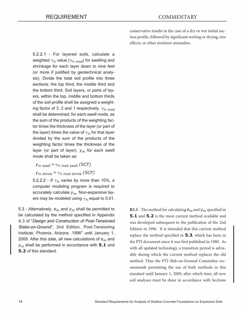
5.1.2.2 - Determine γ0 from Figures 2-7.
5.1.2.3 - Calculate mean value of γh for
actual percentage of fine clays:
5.1.2.4 - Correct γh for swelling or shrinkage:
For swelling (edge lift):
For shrinkage (center lift):
R5.1.1.5 and R5.1.1.6 - For example, assume a total sam-ple weight of 100 grams. 60 grams passes a #200 sieve, andof those 60 grams, 30 grams is smaller than 2 microns.
%-#200 = (60/100)100 = 60%,
%-2μ = (30/100)100 = 30%, and
%fc = (30/60)100 = 50%%fc =
⎛⎝⎜⎜⎜
⎞⎠⎟⎟⎟⎟
%-2%-#200
100μ
R5.1.2.1 - If data does not fall within one of the six zones,use the nearest zone.
R5.1.2.2 - Interpolate between γ0 lines. Beyond extremecontour values, use the nearest values for γ0. Figures
1-7 were derived from National Soil Survey Center,USDA2.
Standard Requirements for Analysis of Shallow Concrete Foundations on Expansive Soils 11
REQUIREMENT COMMENTARY
γ γh fc= % /1000 ( )
γ γ γh e h= h
γ γ γh h
-= e h
5.1.3 - For each significant soil layer described in
5.1.1, calculate Modified Unsaturated Diffusion
Coefficient α' for swelling and shrinkage:
where Ff is determined from Table 1 and:
5.1.4 - For layered soils, calculate α' for swelling
and shrinkage for each layer down to nine feet (or
more if justified by geotechnical analysis). Divide
the total soil profile into three sections, the top third,
the middle third, and the bottom third. Soil layers,
or parts of layers, within the top, middle, and bottom
thirds of the soil profile shall be assigned a weight-
ing factor of 3, 2, and 1 respectively. The weighted
average of α' shall be determined for each swell
mode as the sum of the products of the weighting
factor times the thickness of the layer (or part of
layer) times the value of α' for that layer divided by
the sum of the products of the weighting factor
times the thickness of the layer (or part of layer).
5.1.5 - Determine em for center lift and edge lift
swell modes from Figure 8, using larger value
from Im or α' charts (using weighted α' as
described in 5.1.4).
5.1.5.1 - It shall be permitted to reduce em
with vertical moisture barriers, properly
designed to prevent significant moisture
migration, around entire foundation perime-
ter. Reductions in em as a function of verti-
cal moisture barrier depth shall be taken
from Table 3.
5.2 - Differential Soil Movement ym
5.2.1 - ym shall be determined using computer
methods that determine change in soil surface
elevation at two locations separated by a dis-
tance em. Analysis shall model a layered soil
profile with measured or estimated changes in
R5.2.1 - A commercially available computer program(VOLFLO) for determining ym in accordance with 5.2.1 iscited in Reference 5. In the absence of specific recommenda-tions, controlling soil suction values at the ground surface arerecommended as follows:
α γ' (0.0029-0.000162 -0.0122 )swell h swell= S FS f
α γ' (0.0029-0.000162 -0.0122 )shrink h shrink= S FS f
S LL PIS =-20.29+0.1555( )-0.117( )+
0.0684(%-#200)
12 Standard Requirements for Analysis of Shallow Concrete Foundations on Expansive Soils
REQUIREMENT COMMENTARY
R5.1.4 - The weighting protocol is described in Section3.2.9 of Reference 6. A specific example, with calcula-tions, is presented in Section 3.6.3 of the same reference.

soil suction profile envelopes considering effects
of trees, edge barriers, flower beds, irrigation,
water tables and osmotic suction due to salts.
Standard Requirements for Analysis of Shallow Concrete Foundations on Expansive Soils 13
REQUIREMENT COMMENTARY
1. Wettest: 3.0 pFwhich is a typical low value for a well drainedsite. A 2.5 pF is an extreme suction value that may be used tomodel long term saturation conditions, and should not be usedfor typical design conditions.
2. Driest: 4.5 pFwhich is a typical high value to be used for nor-mal design conditions. A value of 6.0 pF is an extreme upperbound representing long term sun-baked bare ground andshould not be used for typical design conditions.
3. In general, typical design practice for the Post-ConstructionCase should use a suction variance at the ground surface of 1.5pF from wettest to driest or vice-versa. This design case is rec-ommended for geographical areas with Thornthwaite Indicesbetween +15 and -15. The Post-Construction Case assumesswell is calculated from the extreme dry profile to the extremewet profile, with the reverse used for shrink.
4. Geographical areas with Thornthwaite Indices drier than-15 and wetter than +15 should generally use the Post-Equilibrium Case. Unless compelling geotechnical analysisindicates otherwise, a suction profile change of 1.5 pFshould be used with the changes between equilibrium anddry and equilibrium and wet profiles allocated per localpractice. In this case, swell (ym edge) would be calculatedfrom equilibrium to the wet profile and shrink (ym center)would be calculated from equilibrium to the dry profile.
Controlling soil suction values below soil surface are as follows:
1. High Water Table: 2.0pF at the water level unless there isa high osmotic component, in which case, use measuredvalue of suction.
2. Climate-Controlled Suction: Determine by measure-ment at a depth below which the suction varies by lessthan 0.027pF/ft (the z depth).
3. Tree Root Zone: 4.5 pF under driest condition, treenear wilting point.
4. High Osmotic Suction or Cemented Soil: These suctionvalues must be determined by measurement.
R5.2.2 - This method should only be used if a typicaltrumpet-shaped final suction profile can be assumed, andγh does not vary by more than 10% between layers in thesoil profile. Otherwise, this method may not be accurate.Table 2a assumes the initial suction to be at equilibri-um from depth zm to the ground surface, then becomingwet or dry. This limitation would not yield accurate or
5.2.2 - In lieu of computer methods, it shall be
permitted to calculate ym as follows:
5.2.2.1 - For layered soils, calculate a
weighted γh value (γh mod) for swelling and
shrinkage for each layer down to nine feet
(or more if justified by geotechnical analy-
sis). Divide the total soil profile into three
sections: the top third, the middle third and
the bottom third. Soil layers, or parts of lay-
ers, within the top, middle and bottom thirds
of the soil profile shall be assigned a weight-
ing factor of 3, 2 and 1 respectively. γh mod
shall be determined, for each swell mode, as
the sum of the products of the weighting fac-
tor times the thickness of the layer (or part of
the layer) times the value of γh for that layer
divided by the sum of the products of the
weighting factor times the thickness of the
layer (or part of layer). ym for each swell
mode shall be taken as:
ym swell = γh mod swell (SCF)
ym shrink = γh mod shrink (SCF)
5.2.2.2 - If γh varies by more than 10%, a
computer modeling program is required to
accurately calculate ym. Non-expansive lay-
ers may be modeled using γh equal to 0.01.
5.3 - Alternatively, em and ym shall be permitted to
be calculated by the method specified in Appendix
A.3 of "Design and Construction of Post-TensionedSlabs-on-Ground", 2nd Edition, Post-Tensioning
Institute, Phoenix, Arizona .19964 until January 1,
2009. After this date, all new calculations of em and
ym shall be performed in accordance with 5.1 and
5.2 of this standard.
14 Standard Requirements for Analysis of Shallow Concrete Foundations on Expansive Soils
REQUIREMENT COMMENTARY
R5.3 - The method for calculating em and ym specified in5.1 and 5.2 is the most current method available andwas developed subsequent to the publication of the 2ndEdition in 1996. It is intended that this current methodreplace the method specified in 5.3, which has been inthe PTI document since it was first published in 1980. Aswith all updated technology, a transition period is advis-able during which the current method replaces the oldmethod. Thus the PTI Slab-on-Ground Committee rec-ommends permitting the use of both methods in thisstandard until January 1, 2009, after which time, all newsoil analyses must be done in accordance with Sections
conservative results in the case of a dry or wet initial suc-tion profile, followed by significant wetting or drying, treeeffects, or other moisture anomalies.

PART II - SOIL-STRUCTURE ANALYSISREQUIREMENTS
6.0 - METHOD OF CALCULATION
Internal forces and deflections shall be computed
based upon 6.1 or 6.2.
6.1 - Internal forces and deflections shall be calculated
with equations specified in 7.0, 8.0 and 9.0.
6.2 - Alternatively, compute internal forces and
deflections using a properly substantiated finite ele-
ment analysis which considers the interaction of the
foundation and the soil, and incorporates the em and
ym values determined in accordance with 5.0.
7.0 - FLEXURE
Maximum bending moments shall be as specified in
7.1 and 7.2:
7.1 - Center Lift
7.1.1 - Long Direction
where:
R7.0 - FLEXURE
See Reference 7 for background and derivations of theequations specified in 7.0.
A L S h P yo m=1
7270.013 0.306 0.686 0.534 0.193( )
M = A Be +CL o m1.238( )
Standard Requirements for Analysis of Shallow Concrete Foundations on Expansive Soils 15
REQUIREMENT COMMENTARY
Part II includes Sections 6.0 - 9.2.
5.1 and 5.2 of this standard. However, the intent is not thatexisting soils analyses and the related determination ofem and ym be redone unless otherwise required by localcodes and standards.
If em and ym are calculated using the 2nd Editionmethod in accordance with this section, then the founda-tion must be designed using the 2nd Edition structuraldesign procedure as required by Section 1.1 of theStandard Requirements for Design of Shallow Post-
Tensioned Concrete Foundations on Expansive
Soils.

and for 0 ≤ em ≤ 5:
B = 1 and C = 0
and for em > 5:
7.1.2 - Short Direction
For LL/LS ≥ 1.1:
For LL/LS < 1.1:
MS=ML
7.2 - Edge Lift
7.2.1 - Long Direction
7.2.2 - Short Direction
For LL/LS ≥ 1.1:
For LL/LS < 1.1:
MS=ML
Me
MSm
L=58+
60⎛⎝⎜
⎞⎠⎟
M =h+e
MSm
L0.35 19
57.75⎛⎝⎜
⎞⎠⎟
MS he y
L PLm m=
7.2
0.10 0.78 0.66
0.0065 0.04
( )
16 Standard Requirements for Analysis of Shallow Concrete Foundations on Expansive Soils
REQUIREMENT COMMENTARY
CP ym= 8-
-613255
4-3
0⎛⎝⎜
⎞⎠⎟⎛⎝⎜
⎞⎠⎟
≥
Bym=
-13
1.0≤

8.0 - SHEAR
Maximum shear force shall be as specified in 8.1
and 8.2:
8.1 - Center Lift
8.1.1 - Long Direction
8.1.2 - Short Direction
8.2 - Edge Lift
8.2.1 - Long and Short Direction
9.0 - DEFLECTION
Maximum differential deflection shall be as specified
in 9.1 and 9.2:
9.1 - Center lift
9.2 - Edge Lift
R8.0 - SHEAR
See Reference 7 for background and derivations of theequations specified in 8.0
R9.0 - DEFLECTION
See Reference 7 for background and derivations of theequations specified in 9.0.
Δom m=
y L S P eh
( )0.205 1.059 0.523 1.296
1.214380
Δom m=
L S e yh P
0.35 0.86 0.74 0.76
0.85 0.0115.9
V = L S h P y eS m m
11350
0.19 0.45 0.20 0.54 0.04 0.97( )
V L S h P y em mL0.09 0.71 0.43 0.44 0.16 0.93=
11940
( )
V =L h P e y
Sm m
0.07 0.4 0.03 0.16 0.67
0.0153.0
Standard Requirements for Analysis of Shallow Concrete Foundations on Expansive Soils 17
REQUIREMENT COMMENTARY

Table 1 - Soil Fabric Factor
Measured Suction (pF) at Final
Controlling Suction at Surface, pFFinal Controlling Suction at Surface, pF
Depth z 2.5 2.7 3.0 3.5 4.0 4.2 4.5
2.7 +3.2 0 -4.1 -13.6 -25.7 -31.3 -40.0
3.0 +9.6 +5.1 0 -7.5 -18.2 -23.1 -31.3
3.3 +17.7 +12.1 +5.1 -2.6 -11.5 -15.8 -23.1
3.6 +27.1 +20.7 +12.1 +1.6 -5.7 -9.4 -15.8
3.9 +38.1 +30.8 +20.7 +7.3 -1.3 -4.1 -9.4
4.2 +50.4 +42.1 +30.8 +14.8 +3.2 0 -4.1
4.5 +63.6 +54.7 +42.1 +23.9 +9.6 +5.1 0
Table 2a - Stress Change Factor (SCF) for Use in determining ym - Post-Equilibrium Case
18 Standard Requirements for Analysis of Shallow Concrete Foundations on Expansive Soils
Notes:
1. Zm = 9.0 ft.
2. Post-Equilibrium case, which is recommended for use for areas of Thornthwaite Indices more negative than -15and more positive than +15
3. Shaded boxes represent extreme cases.
4. Non-Typical trumpet-shaped suction envelopes or depths to Equilibrium Suction which may vary from 9 ftrequire use of a computer analysis.
Condition Ff
Non CH Soils 1.0
CH Soils
Profile with 1 root, crack, sand/silt seam all less than or equal to 1/8” width/dimension in any com-bination 1.0
Profile with 2 to 4 roots, cracks, sand/silt seams all larger than 1/8” width/dimension in any combi-nation 1.1
Profile with more than 4 roots, cracks, sand/silt seams all larger than 1/8” width/dimension in anycombination 1.2

Depth of Barrier (ft)
2.5 3.0 3.5 4.0 4.5 5.0
em
(Center or Edge)
(ft)
2 2.0 2.0 2.0 2.0 2.0 2.0
3 2.0 2.0 2.0 2.0 2.0 2.0
4 3.1 2.6 2.0 2.0 2.0 2.0
5 4.3 4.0 2.8 2.0 2.0 2.0
6 5.5 5.2 4.2 3.0 2.0 2.0
7 6.5 6.3 5.5 4.5 3.2 2.0
8 7.6 7.4 6.6 5.7 4.7 3.3
9 8.6 8.5 7.7 6.9 6.0 4.9
Table 3 - Values of Reduced em for Various Perimeter Vertical Barriers
Standard Requirements for Analysis of Shallow Concrete Foundations on Expansive Soils 19
Table 2b Stress Change Factor (SCF) for Use in determining ym- Post-Construction Case
Suction Change pF 1.3 1.4 1.5 1.6 1.7 1.8 1.9 2.0
Wetting (Swelling) 33.2 36.7 40.2 43.9 47.6 51.4 55.3 59.2
Drying (Shrinking) -24.3 -26.7 -29.2 -31.7 -34.2 -36.7 -39.3 -41.9
Notes:
1. A suction change of 1.5 pF is recommended; this value has been found to produce designs which are typicaland perform well in Slab-on-Ground design practice. Other values of suction change are offered for engineersto use for special cases or different local practice.
2. Zm = 9.0 ft
3. Table 2b is based on Post-Construction Case which is recommended for areas of ThornthwaiteIndices between -15 and +15.
4. Non-Typical trumpet-shaped suction envelopes or depths to Equilibrium Suction which may vary from 9ftrequire use of computer analysis.

20 Standard Requirements for Analysis of Shallow Concrete Foundations on Expansive Soils
Figure 1 - Mineral Classification Chart

Figure 2 - Zone I Chart for Determining γo
Figure 3 - Zone II Chart for Determining γo
Standard Requirements for Analysis of Shallow Concrete Foundations on Expansive Soils 21

22 Standard Requirements for Analysis of Shallow Concrete Foundations on Expansive Soils
Figure 4 - Zone III Chart for Determining γo
Figure 5 - Zone IV Chart for Determining γo
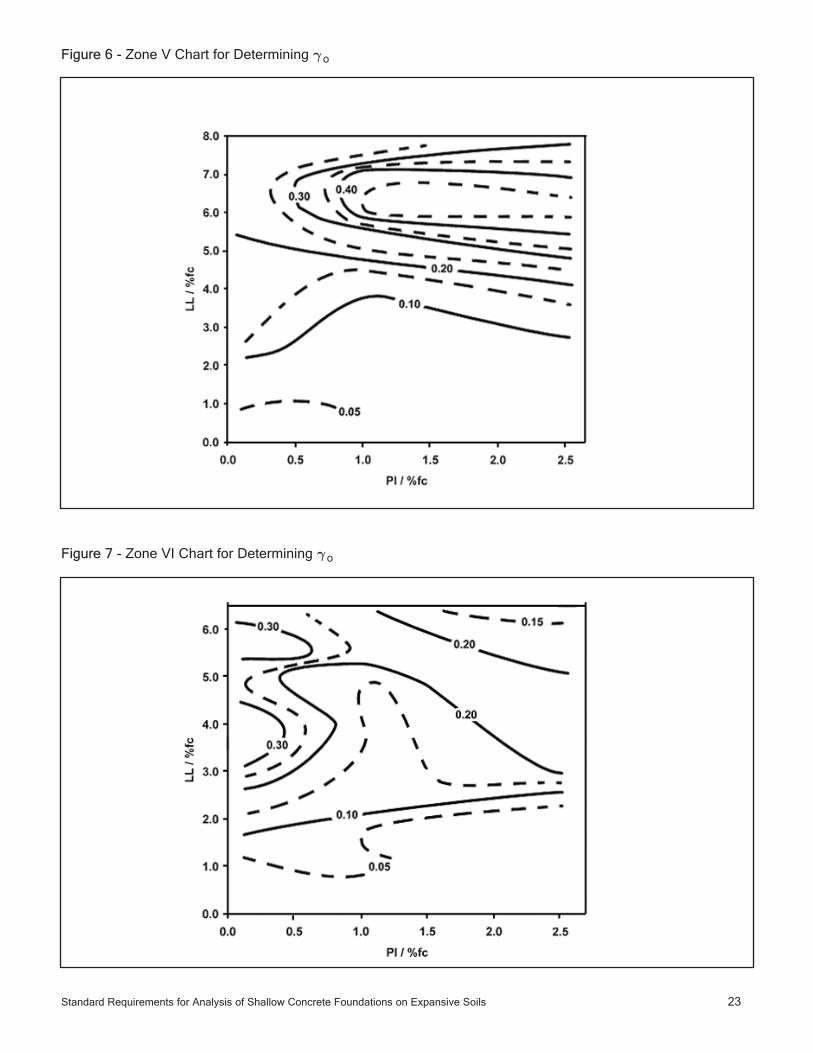
Figure 6 - Zone V Chart for Determining γo
Figure 7 - Zone VI Chart for Determining γo
Standard Requirements for Analysis of Shallow Concrete Foundations on Expansive Soils 23

24 Standard Requirements for Analysis of Shallow Concrete Foundations on Expansive Soils
Fig
ure
8- e m
Sel
ectio
n C
hart
Tho
rnth
wai
te M
oist
ure
Inde
x (I
m)
α',
Wei
ghte
d A
vera
ge o
f M
odifi
edU
nsat
urat
ed D
iffus
ion
Coe
ffici
ent

REFERENCES
1) Building Research Advisory Board, Report #33. (1968). "Criteria for Selection and Design of ResidentialSlabs-on-Ground", National Research Council, Washington, D.C.
2) Covar, A.P. and Lytton, R.L. (2001), "Estimating Soil Swelling Behavior Using Soil ClassificationProperties", ASCE Geotechnical Publication No. 115, American Society of Civil Engineers, Reston, VA,pages 44-63.
3) Lytton, R.L. (1994). "Prediction of Movement of Expansive Clays", ASCE Geotechnical Special PublicationNo. 40, Vol. 2, American Society of Civil Engineers, Reston, VA, pages 1827-1845.
4) Post-Tensioning Institute. (1996). "Design and Construction of Post-Tensioned Slabs-on-Ground", 2ndEdition, Phoenix, AZ.
5) VOLFLO Win 1.0. (2002). A computer program available through the Post-Tensioning Institute orGeostructural Tool Kit, Inc., Austin, Texas.
6) Post-Tensioning Institute (2004), “Design of Post-Tensioned Slabs-on-Ground”, 3rd Edition, Phoenix, AZ
7) Wray, W. K., (1978), “Development of a Design Procedure for Residential and Light Commercial Slabs-on-Ground Constructed Over Expansive Soils”, Dissertation presented in partial fulfillment of the requirementsfor the degree of Doctor of Philosophy to Texas A&M University at College Station, TX.
Standard Requirements for Analysis of Shallow Concrete Foundations on Expansive Soils 25

8601 N. Black Canyon Hwy., Suite 103Phoenix, AZ 85021Telephone: (602) 870-7540Fax: (602) 870-7541Website: www.post-tensioning.org