standard operating procedures for - … operating procedures for thermo environmental model 42i...
TRANSCRIPT

SANTA BARBARA COUNTY AIR POLLUTION CONTROL DISTRICT
STANDARD OPERATING PROCEDURES
FOR
THERMO ENVIRONMENTAL MODEL 42i Oxides of Nitrogen ANALYZER
August 2017
SBCAPCD SOP Thermo Environmental 42i Oxides of Nitrogen Analyzer
First Revision, August 2017
1
SANTA BARBARA COUNTY AIR POLLUTION CONTROL DISTRICT
Approval of Standard Operating Procedures (SOP)
THERMO ENVIRONMENTAL MODEL 42i OXIDES OF NITROGEN ANALYZER
SBCAPCD SOP Thermo Environmental 42i Oxides of Nitrogen Analyzer
First Revision, August 2017
2
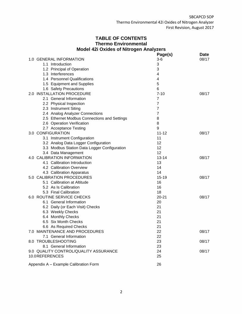
TABLE OF CONTENTS Thermo Environmental
Model 42i Oxides of Nitrogen Analyzers Page(s) Date 1.0 GENERAL INFORMATION 3-6 08/17
1.1 Introduction 3
1.2 Principal of Operation 3
1.3 Interferences 4
1.4 Personnel Qualifications 4
1.5 Equipment and Supplies 5
1.6 Safety Precautions 6
2.0 INSTALLATION PROCEDURE 7-10 08/17
2.1 General Information 7
2.2 Physical Inspection 7
2.3 Instrument Siting 7
2.4 Analog Analyzer Connections 7
2.5 Ethernet Modbus Connections and Settings 8
2.6 Operation Verification 8
2.7 Acceptance Testing 9
3.0 CONFIGURATION 11-12 08/17
3.1 Instrument Configuration 11
3.2 Analog Data Logger Configuration 12
3.3 Modbus Station Data Logger Configuration 12
3.4 Data Management 12
4.0 CALIBRATION INFORMATION 13-14 08/17
4.1 Calibration Introduction 13
4.2 Calibration Overview 14
4.3 Calibration Apparatus 14
5.0 CALIBRATION PROCEDURES 15-19 08/17
5.1 Calibration at Altitude 16
5.2 As Is Calibration 16
5.3 Final Calibration 18
6.0 ROUTINE SERVICE CHECKS 20-21 08/17
6.1 General Information 20
6.2 Daily (or Each Visit) Checks 21
6.3 Weekly Checks 21
6.4 Monthly Checks 21
6.5 Six Month Checks 21
6.6 As Required Checks 21
7.0 MAINTENANCE AND PROCEDURES 22 08/17
7.1 General Information 22
8.0 TROUBLESHOOTING 23 08/17
8.1 General Information 23
9.0 QUALITY CONTROL/QUALITY ASSURANCE 24 08/17
10.0 REFERENCES 25
Appendix A – Example Calibration Form 26

SBCAPCD SOP Thermo Environmental 42i Oxides of Nitrogen Analyzer
First Revision, August 2017
3
1.0 GENERAL INFORMATION
1.1 Introduction This Standard Operating Procedure (SOP) describes procedures used by the Santa Barbara County Air Pollution Control District (SBCAPCD) to operate the Thermo Environmental (TEI) Model 42i to measure Oxides of nitrogen levels in ambient air. This procedure is designed to supplement the instruction manual by describing hardware or operating procedures as implemented by the SBCAPCD for monitoring of Oxides of nitrogen in the District’s ambient air monitoring network. It is not the intent of this SOP to duplicate or replace the instruction manual. 1.2 Principle of Operation The TEI 42i Nitrogen Oxides Analyzer is a microprocessor controlled instrument that determines the concentration of nitric oxide (NO), total nitrogen oxides (NOX, the sum of NO and NO2) and nitrogen dioxide (NO2) in a sample gas drawn through the instrument. The instrument measures the amount of NO present in a gas by detecting the chemiluminescence which occurs when nitrogen oxide (NO) is exposed to ozone (O3). This reaction is a two-step process:
In the first step, one molecule of NO and one molecule of O3 collide and chemically react to produce one molecule of oxygen (O2) and one molecule of nitrogen dioxide (NO2). Some of the NO2 molecules created by this reaction retain excess energy from the collision and exist in an excited state, where one of the electrons of the NO2 molecule resides in a higher energy state than normal (denoted by an asterisk in the following equation).
NO O3 NO2* O2
The second step occurs because the laws of thermodynamics require that systems seek the lowest stable energy state available, therefore the excited NO2 molecule quickly returns to its ground state, releasing the excess energy. This release takes the form of a quantum of light (hv). The distribution of wavelengths for these quanta range between 600 and 3000 nm, with a peak at about 1200 nm.
NO2* NO2+ hv 1200nm
All things being constant (temperature, pressure, amount of ozone present, etc.), the relationship between the amount of NO present in the reaction cell and the amount of light emitted from the reaction is very linear. If more NO is present, more IR light is produced. By measuring the amount of IR light produced with a sensor sensitive in the near-infrared spectrum the amount of NO present can be determined.
SBCAPCD SOP Thermo Environmental 42i Oxides of Nitrogen Analyzer
First Revision, August 2017
4
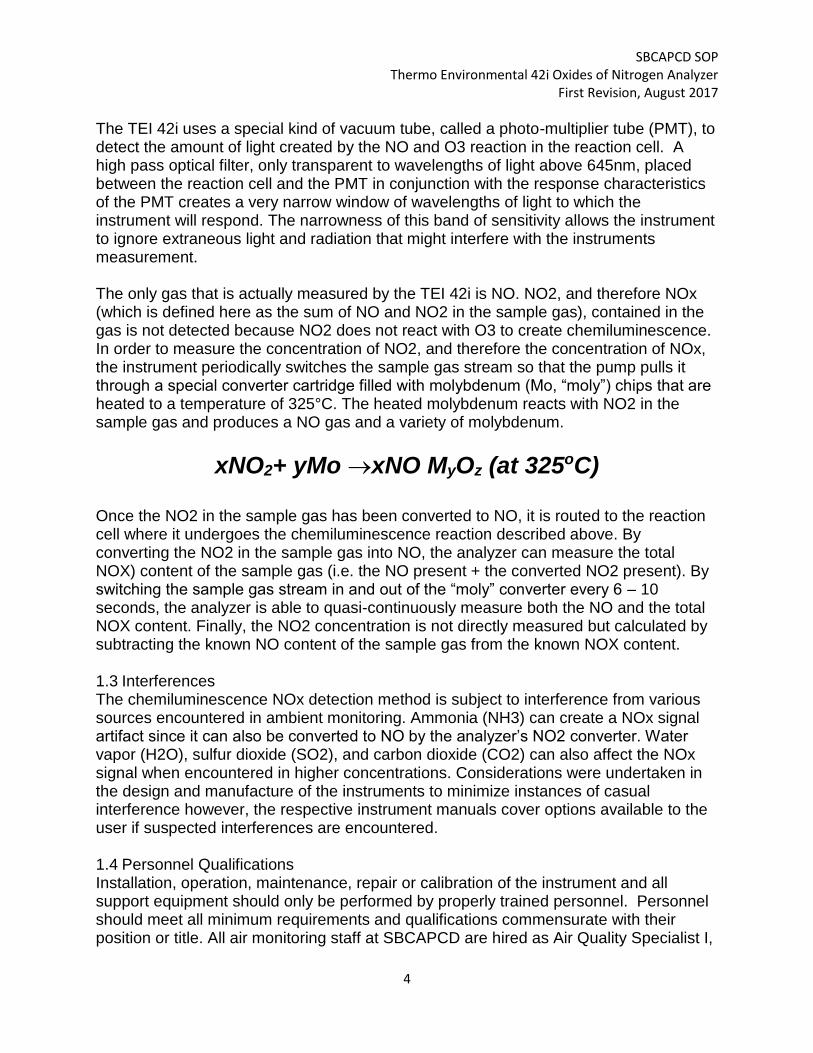
The TEI 42i uses a special kind of vacuum tube, called a photo-multiplier tube (PMT), to detect the amount of light created by the NO and O3 reaction in the reaction cell. A high pass optical filter, only transparent to wavelengths of light above 645nm, placed between the reaction cell and the PMT in conjunction with the response characteristics of the PMT creates a very narrow window of wavelengths of light to which the instrument will respond. The narrowness of this band of sensitivity allows the instrument to ignore extraneous light and radiation that might interfere with the instruments measurement. The only gas that is actually measured by the TEI 42i is NO. NO2, and therefore NOx (which is defined here as the sum of NO and NO2 in the sample gas), contained in the gas is not detected because NO2 does not react with O3 to create chemiluminescence. In order to measure the concentration of NO2, and therefore the concentration of NOx, the instrument periodically switches the sample gas stream so that the pump pulls it through a special converter cartridge filled with molybdenum (Mo, “moly”) chips that are heated to a temperature of 325°C. The heated molybdenum reacts with NO2 in the sample gas and produces a NO gas and a variety of molybdenum.
xNO2+ yMo xNO MyOz (at 325oC)
Once the NO2 in the sample gas has been converted to NO, it is routed to the reaction cell where it undergoes the chemiluminescence reaction described above. By converting the NO2 in the sample gas into NO, the analyzer can measure the total NOX) content of the sample gas (i.e. the NO present + the converted NO2 present). By switching the sample gas stream in and out of the “moly” converter every 6 – 10 seconds, the analyzer is able to quasi-continuously measure both the NO and the total NOX content. Finally, the NO2 concentration is not directly measured but calculated by subtracting the known NO content of the sample gas from the known NOX content. 1.3 Interferences The chemiluminescence NOx detection method is subject to interference from various sources encountered in ambient monitoring. Ammonia (NH3) can create a NOx signal artifact since it can also be converted to NO by the analyzer’s NO2 converter. Water vapor (H2O), sulfur dioxide (SO2), and carbon dioxide (CO2) can also affect the NOx signal when encountered in higher concentrations. Considerations were undertaken in the design and manufacture of the instruments to minimize instances of casual interference however, the respective instrument manuals cover options available to the user if suspected interferences are encountered. 1.4 Personnel Qualifications Installation, operation, maintenance, repair or calibration of the instrument and all support equipment should only be performed by properly trained personnel. Personnel should meet all minimum requirements and qualifications commensurate with their position or title. All air monitoring staff at SBCAPCD are hired as Air Quality Specialist I,

SBCAPCD SOP Thermo Environmental 42i Oxides of Nitrogen Analyzer
First Revision, August 2017
5
II, III, or Monitoring/IT Supervisor positions. Qualifications for the respective staff functions are typically first established through the successful completion of a probationary period with supervisorial oversight. Successive levels of responsibility are achieved via internal and external training classes, experience and a demonstrated display of abilities until a “journey level” is attained. 1.5 Equipment and Supplies Instrumentation, spare parts, and consumables such as Teflon sample filters, Teflon tubing, and other material used in air monitoring activities are stored in the SBCAPCD laboratory for use by monitoring staff. Standard site installation requires analyzers, calibration systems, and data acquisition systems to be properly integrated to allow for automated calibrations and acquisition of data. Calibration systems are maintained and certified by the station operator. Consumable supplies, required for regular scheduled maintenance are also stored at the respective sites as needed. Supplies are ordered by the Monitoring Supervisor or his designee with consideration for adequate lead times. Station operators are required to notify the Monitoring Supervisor as stock of consumables are depleted to the point where new purchases are required. Some of the specific items critical to the successful operation of the TEI 42i NOx analyzer are listed below with the vendor where the items are typically purchased:

SBCAPCD SOP Thermo Environmental 42i Oxides of Nitrogen Analyzer
First Revision, August 2017
6
Item Description Vendor
¼” Tubing ¼” OD, 5/32” ID FEP Teflon Tubing
Savillex, Inc.
Tubing Fittings Various PFA Teflon compression fittings
Cole Parmer, Inc.
Sample Filters 5 micron pore size, 47 mm diameter PTFE Teflon Filter Membranes
Savillex, Inc.
Sample Manifold/Inlet 25mm OD borisilicate glass inlet with CARB style manifold. Equipped with PTFE isolating bushings and plugs
Ace Glass, Inc.
Power and most Cables 3 prong AC cable and most cables utilized with analyzer are provided upon initial purchase.
Thermo Fisher Scientific
Ethernet Cable CAT5e or better Ethernet
Cable
Compuwave
Calibration System TAPI 700 (equipped with TAPI 701 zero air system).
Teledyne API
Compressed NO Gas Standard
Compressed gas cylinder containing NO in nitrogen traceable to NIST standards by EPA protocol. Nominal concentration of ~60 ppm.
Scott Marrin, Inc.
1.6 Safety Precautions Prior to cleaning the analyzer or performing any maintenance on the instrument, place the MAIN power switch to the OFF position, and unplug the power cord. Avoid the use of chemical agents which might damage components. Always use a three-prong, grounded plug on this analyzer. Adhere to general safety precautions when using compressed gas cylinders (e.g., secure cylinders, vent exhaust flows). The analyzer exhausts ozone, operators should ensure that the exhaust is vented outside the shelter, that sample pump charcoal filter is replaced at the required intervals, and that no leaks develop during operation.

SBCAPCD SOP Thermo Environmental 42i Oxides of Nitrogen Analyzer
First Revision, August 2017
7
2.0 INSTALLATION PROCEDURE
2.1 General Information: The instrument is designed and has received EPA equivalency with an operating temperature range between 15ºand 35C. To provide added assurance of stable operating temperature, a stable shelter temperature between 20-30 ºC is preferred. Care should be taken to install the instrument in a standard 19” instrument rack such that it can be accessed for maintenance, repair work and troubleshooting etc. The standard 19” instrument racks should be bolted to the floor and properly grounded. 2.2 Physical Inspection: The instrument is normally shipped with the following standard equipment:
1. Power cord 2. Instruction manual 3. Side rails Upon receiving the instrument, confirm that the instrument is in good working order and inspect for damage. If any damage is observed, contact the IT/monitoring supervisor. Prior to installation of the instrument, check the following:
1. Verify no apparent shipping damage. 2. Check that all connectors are fully inserted. 3. Check that all mechanical connections are tight. 4. Open and remove the internal shipping screws on the pump and the internal foam blocks (See Chapter 2 of the instrument manual for more detail). 2.3 Instrument Siting The instrument should be sited in accordance with the United States Environmental Protection Agency (U.S. EPA) Title 40, Code of Federal Regulations Part58 Appendix E “Probe and Monitoring Path Siting Criteria for Ambient Air Quality Monitoring” and USEPA Designated Automated Equivalent Method RFNA-1289-074. 2.4 Analog Analyzer Connections The instrument I/O connector (analog output, digital input, and power fail contact), digital output, I/O expansion, external accessory, serial and Ethernet connectors are located on the rear panel. The instrument analog output is configured on the main I/O connector on the rear panel. While the primary NOX concentration acquisition for these analyzers is via Ethernet Modbus, a back-up analog output connection is set up upon analyzer installation. The back-up analog output NO/NO2/NOx concentration connections are found on pin 14 (NO), 33 (NO2), and 15 (NOx) (positive) and pin 16 (negative or ground) of the main I/O connector. See instrument manual Chapter 3. As SBCAPCD does not utilize analog strip charts or the IZS option, no other analog connections are required.

SBCAPCD SOP Thermo Environmental 42i Oxides of Nitrogen Analyzer
First Revision, August 2017
8
2.5 Ethernet Modbus Connections and Settings The primary data acquisition method utilized for NO/NO2/NOX concentration and analyzer operational data is Modbus protocol via Ethernet connection. Each monitoring station utilizes an internal Ethernet network that connects each analyzer to the station data logger (Agilaire 8872 or 8832) through an Ethernet switch or hub. The NOX analyzer is configured for static IP communications following the procedures outlined in the instrument manual, section 6.5.1 using the appropriate IP address (192.168.xxx.x, Gateway IP (192.168.xxx.1), and Subnet Mask (255.255.255.0) as configured in the data logger for this instrument. Modbus protocol is enabled. Following making the above IP configurations on the analyzer, and connecting the analyzer to the station LAN, ensure that the data system is gathering data from the instrument. If not already configured, configure the station data logger for the appropriate channels to gather NO/NO2/NOX concentration as well as all operational parameters following the data logger manual’s procedures. Once the data logger is properly configured, confirm that all channels are correctly gathering data from the NOX analyzer. 2.6 Operation Verification NOTE: Prior to operation of the instrument, operators must read the respective instruction manual to familiarize themselves with the operation of the instrument. Prior to operating the 42i, ensure that the proper connections have been made. In summary, at most SBCAPCD monitoring locations this involves the following connections:

SBCAPCD SOP Thermo Environmental 42i Oxides of Nitrogen Analyzer
First Revision, August 2017
9
• Connect the sample inlet line from the manifold to the sample port on the rear panel. • Connect the pump exhaust to a suitable vent outside the analyzer area. • Connect the power cord to a well-grounded and appropriate power outlet. • Connect recording devices to the terminal strip and LAN connections on the rear panel. After proper connections have been made, turn on the power switch. At initial power on, the 42i the display will show a “power up” screen, indicating that the instrument is booting up. Following boot up, the normal “Run Screen” will display, indicating the NOX concentration, status bar, and time. Allow approximately one hour for the instrument to stabilize before performing any further operations. Review all diagnostic values by accessing the diagnostic menu following the procedure outlined in Chapter 3 – Diagnostic Menu in the instrument manual. Compare these values to those listed on the factory final checkout sheet in the instruction manual, and/or the values listed in site records from previous the installation of this instrument. Should any operational parameters values exceed allowable tolerance, the instrument will automatically generate an alarm notification on the front panel. If any alarm messages persist after the 60 minute warm up period is over, investigate their cause using the troubleshooting guidelines provided in the instruction manual. 2.7 Acceptance Testing Prior to field deployment, all new instruments are tested in the SBCAPCD laboratory to ensure proper operation prior to collecting data for record. The instrument is set up in the SBCAPCD laboratory following the same procedures outlined in this SOP for setting an instrument up in a monitoring station. The SBCAPCD laboratory is equipped with a data logger (polled by the central AirVision server) and certified calibration system, mimicking the station set up. After the instrument has been set up, configured, and warmed up for a minimum of one hour, a manual zero span is performed to allow adjustment of zero and span responses to match the certified test gas concentrations. Next, a multi-point calibration is performed to establish linearity, following the general procedure outlined in this Section 5 of this SOP. The instrument is maintained in the laboratory mock station set up for one week, with automated multi-point calibrations performed daily to track zero and span drift as well as confirming the analyzers linear response. At the end of the week long acceptance test period, the instrument is evaluated to ensure the following criteria are met:

SBCAPCD SOP Thermo Environmental 42i Oxides of Nitrogen Analyzer
First Revision, August 2017
10
Parameter Pass Criteria
Maximum zero drift for 7 day period +/- 1.5 ppb
Maximum span drift for 7 day period 5%
Converter Efficiency >98%CE
Passing linearity on each Multi-point Calibration
All points within +/- 2 % of calibration range of best-fit straight line
Operational Parameters Well within allowable range as listed in Instrument manual.
If the results of the testing is within allowable criteria, the instrument can be deployed to the field for operation. The calibration results and records of operational parameters recorded by the lab data logger and polled by the central AirVision DAS are copied and permanently stored in the Instrument Records section of the District’s SharePoint intranet site. Should the testing results not meet one or more criteria, the instrument is not deployed to the field and either returned to the vendor or corrective action is taken by Monitoring staff, followed by a repeat of the week long acceptance testing procedure until all criteria are met.

SBCAPCD SOP Thermo Environmental 42i Oxides of Nitrogen Analyzer
First Revision, August 2017
11
3.0 CONFIGURATION
3.1 Instrument Configuration Prior to initiating monitoring for record, the instrument is properly configured for basic parameters prior to field use. Table 1 below shows the Thermo Environmental 42i configuration utilized at SBCAPCD. Chapter 3 of the instrument manual provides the details on confirming and/or changing these settings as well as overall discussion on Instrument Operation.
Parameter Configured Value
Range mode Single Range
Measurement Units ppb
Measurement Range 500 ppb
Analog Output Range 0-5VDC
Averaging Time 60 Seconds
Temperature Compensation ON- 30DegC
Pressure Compensation ON- 750mmHg
Table1a: Standard SBCAPCD Thermo Environmental 42i Basic Configuration
Parameter Nominal Value Factory Alarm Tolerance
Internal Temperature 30 Deg C 15-45 Deg C
Chamber Temperature 49 Deg C 47-51 Deg C
Cooler Temperature -10 Deg C -20 to -1 Deg C
Converter Temperature 325 Deg C 300 – 350 Deg C
Pressure 230 mmHg 150 – 300 mmHg
Sample Flow 0.700 l/m 0.500 – 1.0 l/m
Ozonator Flow 0.200 l/m >.05 l/m
Table 1b: Operational Parameters (not adjustable except alarm tolerance) and Alarm Tolerance for TEI 42i The Thermo Environmental 42i provides an internal data logging function. This internal data logging function is utilized as a back-up record of NOX concentration in the event of a failure of the primary data system. Chapter 3 of the instrument manual provides details on configuration of the 42i internal data logging function. Table 2 below, provides the standard SBCAPCD configuration utilized for the internal data logging function. As the internal data logging function is utilized in the rare case of a failed primary data system, the logging function is configured to store only short records (srec) every minute logging only the NO/NO2/NOX average concentrations.

SBCAPCD SOP Thermo Environmental 42i Oxides of Nitrogen Analyzer
First Revision, August 2017
12
Parameter Configured Value
srec-Select Content NO Concentration NO2 Concentration NOx Concentration
srec-Other Measurements None
srec-Logging Period 1 minute
srec-Memory Allocation % 100%
srec-Data Treatment Average
3.2 Analog Data Logger Configuration Analog data logger channel configuration for the instrument can be found in the operating manual for the data logger model you are using. The data logger channel for the oxides of nitrogen analyzer is configured for a 0 to 5 volt signal equaling 0 to 500 ppb assuming the range of the instrument is set to 500 ppb. As noted above the instrument is configured to single range, 0-500 ppb following the appropriate section in the instrument manual. Note that the analog signal is only utilized in the event that the primary, Modbus connection is not available. 3.3 Modbus Station Data Logger Configuration: The 8872 or 8832 site data logger records minute data for concentration data as well as all operational data from the oxides of nitrogen analyzer. Primary data acquisition is accomplished by Ethernet connection using Modbus protocol. Instructions on data logger configuration are provided in the appropriate data logger instrument manual. Following configuration, the site operator will monitor the instrument and data logger to ensure the configuration has resulted in the correct acquisition of data. 3.4 Data Management Data acquisition, data calculations, and data storage/transmittal are described in the SBCAPCD Data Review and Validation SOP.

SBCAPCD SOP Thermo Environmental 42i Oxides of Nitrogen Analyzer
First Revision, August 2017
13
4.0 CALIBRATION INFORMATION
4.1 Calibration Introduction: A calibration is a procedure for aligning or checking the output of an instrument to a known “true” standard. To ensure the quality of the data provided by the TEI 42i, in general the analyzer must be calibrated in accordance with recommendations stated in this SOP. A multi-point calibration is utilized to establish that the instrument response is linear across the measurement range and to confirm that the instrument zero and span drift meets established criteria. A zero/span calibration is utilized to confirm zero and span drift, but does not confirm linearity. Precision or “One Point QC Checks” are utilized to calculate quality statistics and also verify the analyzer is within allowable tolerance. The SBCAPCD utilizes a variety of field calibrations for various situations and purposes that fall into two general categories, nominally referred to as “AS-IS” and “Final” calibrations. An “AS-IS” calibration is performed initially to evaluate the instruments accuracy. No adjustments, modifications or repairs are made to the instrument prior to the “AS-IS” calibration. This calibration verifies instrument accuracy of the recently generated data; usually back to the previous calibration check. A “Final” calibration is performed after an instruments “AS-IS” calibration exceeds adjustment limits, or has undergone major maintenance or repair. If the “AS-IS” calibration (zero/span or multi-point) shows the instrument’s response outside of adjustment limits, and there is no indication of loss of linear response and it appears the out of tolerance condition is due to normal instrument drift, the analyzer zero and/or span is adjusted, followed by a zero/span calibration. However, if an “AS-IS” multi-point shows a non-linear response, it appears the out of tolerance condition is not due to normal instrument drift, converter efficiency is less than 96%, and/or repair or maintenance was performed that potentially could influence the linearity of response, a full “Final” multi-point calibration is required. Automated “AS-IS” zero, span and/or precision checks are typically performed six days a week, providing daily confirmation that the analyzer response to test gas near ambient concentrations and/or the NAAQS is within required tolerance as well as meeting the requirement of a valid precision check at least every 14 days. An automated “AS-IS” zero, ~80% span, midpoint, and precision point are performed once each week. This automated zero and three upscale multi-point calibration provides confirmation of linearity as well as establishing that the analyzer response is within allowable tolerance across the entire measurement range of the analyzer. Full zero and 4 upscale point, multi-point calibrations are performed manually or automatically once a month and whenever repairs that could influence analyzer linearity and/or adjustments not due to normal instrument drift are performed. Typically the full “AS-IS” multi-point is performed prior to repair or adjustment needed for reasons other

SBCAPCD SOP Thermo Environmental 42i Oxides of Nitrogen Analyzer
First Revision, August 2017
14
than normal instrument drift, followed by a “Final” full multi-point. The full “final” multi-point performed following adjustment and/or repair can be performed automatically as the next night’s auto-calibration, however should the automated multi-point not meet required tolerances, data will be invalidated back to the time of the repair/adjustment and a new full multi-point must be performed that meet all tolerances before data can be considered valid.
Parameter Criteria
Zero Drift Adjustment <=+/-1.5ppb
Span Drift Adjustment <=+/-7%
One-Point QC Corrective Action <=+/- 10%
Converter Efficiency 96-104%
Linearity Criteria for Multi-Point All points < +/- 2.1 % or < +/-1.5 ppb difference of best-fit straight line whichever is greater
Final Multi-point Slope 1.0 +/- 0.05
Table 2 – Instrument adjustment, converter efficiency, and linearity criteria 4.2 Calibration Overview: Test concentrations must be obtained in accordance with the calibration procedures listed in 40 CFR 50 Appendix F, Measurement Principle and Calibration Procedure for the Measurement of Nitrogen Dioxide in the Atmosphere (Gas Phase Chemiluminescence). This procedures utilizes the dilution of certified compressed gas nitric oxide standards with zero air to generate appropriate test gas concentrations needed to calibrate the NO and NOx channels of the instrument. Nitrogen Dioxide test gas concentrations are generated by the gas phase titration of the NO test gas. Both the concentrated gas cylinder and the dilution flow controllers must be certified and traceable to NIST standards. It is recommended that the test concentration for NO/NO2/NOx should be delivered directly into the station sample manifold. 4.3 Calibration Apparatus: Field calibrations of NO/NO2/NOx analyzers are performed utilizing the site calibration system (typically TAPI 700E or T700). The in-station calibration system is equipped with certified compressed gas cylinder, zero air generator, a stable ozone generator, and flow controllers. The compressed gas cylinder is certified, following the EPA certification procedures outlined in the EPA guidance document, “EPA Traceability Protocol for Assay and Certification of Gaseous Calibration Standards”, May 2012 (EPA/600/R-12/531). The station dilution flow controller’s certification is performed every 6 months in the SBCAPCD laboratory using the SBCAPCD NIST traceable flow standards. Refer to the SBCAPCD TAPI T700/700E Dilution Calibration System SOP for details on calibrator operation. All calibration gas is input directly to the station sample manifold, with excess flow vented out the inlet.

SBCAPCD SOP Thermo Environmental 42i Oxides of Nitrogen Analyzer
First Revision, August 2017
15
5.0 CALIBRATION PROCEDURES
To ensure the quality of the data collected within the SBCAPCD’s air monitoring network, ALL instruments used in the network must be calibrated by a full multi-point calibration • during initial field installation and every six months thereafter, • following physical relocation, • after any major maintenance or repair that could potentially influence linearity, A simplified zero/span calibration can be utilized to adjust zero/span when the instrument response is outside adjustment limits shown in Table 2 above as long as there is no indication of loss of linear response or converter efficiency 96-104% and that the out of tolerance condition is likely due to normal instrument drift. Instrument calibrations at all stations within the SBCAPCD network shall be performed in a consistent manner, so that all network monitoring stations are calibrated in a similar fashion. Instruments must be calibrated in accordance with the appropriate SOP and/or appropriate instruction manual. Full multi-point instrument calibrations should be conducted such that all instruments are challenged at a minimum of four (4) different nitric oxide gas concentrations and a zero check first for the NO/NOx channels of the instrument, followed by challenging at a minimum of four (4) different nitrogen dioxide gas concentrations for the NO2 channel of the instrument. The high calibration point should be at a level approximately 85% of the instrument’s full analog scale for NO/NOx and approximately 75% for NO2. The low calibration point for both NO and NO2 should meet the requirements of 40 CFR Part 58 App A Sec 3.1.1. A zero/span calibration is conducted by challenging the instrument with a zero check and a high calibration point at a level approximately 85-75% (NO as well as NO2) of the instruments full scale. SBCAPCD also performs a three upscale point (NO/NOx and NO2) multi-point calibration used to confirm a linear response and to evaluate analyzer response across the measurement range of the analyzer. SBCAPCD performs daily automated calibrations “AutoCals”. Six days a week the AutoCals may include the completion of a zero/precision (“one point QC check”), a zero/span check, or a zero/precision/span check on a rotational basis following all EPA requirements. The automated weekly “AS IS” three point upscale multi-point calibration provides added assurance of instrument linearity. Once a month, and in conjunction with any repairs that could influence analyzer linearity and/or adjustments not due to normal analyzer drift, SBCAPCD performs a full four upscale point “full” multi-point calibrations. All calibrations are performed utilizing the in-station calibration system which includes the use of NIST traceable gas standards.

SBCAPCD SOP Thermo Environmental 42i Oxides of Nitrogen Analyzer
First Revision, August 2017
16
Results of both automated and manual calibrations (both the analyzer and photometer results) are captured and stored by the station data logger, later transmitted and stored in the AirVision central data system database. Other calibration details for manual calibrations are recorded in the station log. Whenever data is bracketed in time by one or more calibration checks outside of allowable tolerances (zero <+/-3.1 ppb, span points <+/-10.1%, 1-pt QC <+/-15.1%, CE 96-104%), that data must be invalidated and corrective action to bring the analyzer back into tolerance must be taken. The procedures for handling data associated with out of tolerance conditions are outlined in detail in Section 6 of the SBCAPCD Data Review and Validation SOP. 5.1 Calibration at Altitude Calibrating the instrument at altitude requires no special adjustments because it compensates for changes in temperature and pressure. Prior to calibration, verify the operation of the internal pressure transducers in the instrument by recording the values of temperature and pressure from the instrument and from a certified transfer standard for one point. NOTE: The air monitoring stations data acquisition system (DAS) is used for primary data recording, therefore the stations DAS data values should be used for calibration calculations in lieu of the analyzer display readings. 5.2 As Is Calibration AS-IS instrument calibrations should be made prior to making any analyzer repairs or adjustments. AS-IS calibrations can be automated or manually performed. The dedicated station calibration system, traceable to authoritative flow and NO gas standards, is utilized for these calibrations. Both the automated calibrations and any necessary manual calibrations are controlled and recorded by the station data logger. The data logger will control the station calibration system through either contact closure or Modbus commands. The data logger is also programmed to automatically capture the response of the analyzer for each calibration point performed. The data logger is programmed to step through the calibration sequence, running each point long enough for a minimum of 5 minutes of stable trace from NO/NO2/NOx channels based on historical response time for that site’s equipment. The analyzer operational information typically recorded on a calibration form (slope, intercept, flow, etc.) is automatically being recorded real time by the station data logger and stored in the AirVision database. Any additional information needed to document manual calibrations is entered in the site logbook. The data logger calibration program is configured to perform the following sequence (points 1-9) for “full” multi-point calibrations with zero/span calibrations consisting of only Points 1,2 and 6. The three upscale point multi-point calibrations consist of Points 1,2,6,5,9, and a mid-point with a target NO concentration of 108 ppb and the NO2 GPT (to point 2), set for a target NO2 concentration of 180 ppb.

SBCAPCD SOP Thermo Environmental 42i Oxides of Nitrogen Analyzer
First Revision, August 2017
17
Point 1 – Zero Point 2 – Target NO Concentration of 430 ppb Point 3 – Target NO Concentration of 250 ppb Point 4 – Target NO Concentration of 125 ppb Point 5 – Target NO Concentration of 50 ppb Point 6 – Dilution set to Point 2, GPT set for target NO2 concentration of 380 ppb Point 7 – Dilution set to Point 2, GPT set for target NO2 concentration of 250 ppb Point 8 – Dilution set to Point 2, GPT set for target NO2 concentration of 125 ppb Point 9 – Dilution set to Point 2, GPT set for target NO2 concentration of 50 ppb Following each three or four upscale multi-point calibration that is performed (automated or manual), the results must be validated. The procedure for validating a multi-point calibration is as follows: 1) Run a calibration result report in AirVision for the calibration being validated. 2) Review the NO/NO2/NOx analyzer electronic strip charts for each point of the calibration. Ensure that for each point the captured result on the AirVision report matches the stable reading on the charts. For a calibration point to be considered stable, it should be a constant value, not trending upwards or downwards for at a minimum the last 5 minutes of the calibration point. If any calibration points that were stable, but the captured value is incorrect, edit the AirVision calibration database to correctly reflect the analyzer response. If any calibration points did not meet the stability requirement, exclude these points from the AirVision calibration database. 3) Confirm that the compressed gas cylinder and dilution flow controller certifications were valid at the time of the calibrations. Also confirm that the true diluted concentration for each point in AirVision correctly reflects the dilution ratio and cylinder concentration with the flow certification applied. If either of these certifications were not valid, exclude all points of the calibration from the AirVision database and immediately take corrective action to ensure valid certifications for the compressed gas cylinder and dilution flow controllers, and re-run the multi-point calibration. 4) Confirm that the database tracking equipment locations, lists the correct NO/NO2/NOx analyzer and calibrator utilized for this calibration. If the equipment tracking database is incorrect, make the corrections to the database. 5) If any of the validation steps resulted in exclusion of calibration points, take the necessary corrective action and re-run the calibration. 6) The site data logger is programmed to automatically calculate the True NO2 points generated in the GPT portion of the calibration using the following formula:
Where: [NO2]OUT = diluted NO2 concentration at the output manifold [NO]orig = original NO concentration, prior to addition of O3 (NOresponse/NOslope). [NO]rem = NO concentration remaining after addition of O3 (NOresponse/NOslope).

SBCAPCD SOP Thermo Environmental 42i Oxides of Nitrogen Analyzer
First Revision, August 2017
18
These true concentrations are stored as the expected true value concentrations and are used in all calibrations reports. 7) After passing the above validation steps, review the calibration result report to ensure that the analyzer linearity meets the criteria listed in Table 2 above. Should the linearity criteria not be met, corrective action is taken to correct the non-linear response, followed by a full multi-point calibration as outlined in section 5.3 of this SOP. 8) For each NO2 concentration generated calculate the concentration of NO2 converted using the following formula:
Where: [NO2]CONV = concentration of NO2 converted [NOX]orig = original NOX concentration prior to addition of O3 [NOX]rem = NOX concentration remaining after addition of O3 Plot [NO2]CONV (y-axis) versus [NO2]OUT (x-axis) and draw or calculate the converter efficiency curve. The slope of the curve times 100 is the average converter efficiency, EC The average converter efficiency must be 96-104%; if it is less than 96%, replace or service the converter. If CE>104% the instrument has excessive drift or there are errors in the CE calculation. Document the converter efficiency in the site log. Should the converter efficiency criteria not be met, corrective action is taken followed by a full multi-point calibration as outlined in section 5.3 of this SOP. Following all “AS IS” calibrations, zero and span drift is evaluated by the criteria listed in Table 2. If the zero and/or span response is outside of adjustment criteria, the instrument is adjusted and a final calibration is performed following the procedure in Section 5.3 of this SOP. Should the “as is” calibration results show any out of tolerance conditions, data will be invalidated back to the last period of data bracketed by checks showing in tolerance conditions. See SBCAPCD Data Review and Validation for more details. 5.3 Final Calibration As previously stated a Final calibration is conducted when an AS-IS calibration exceeds zero/span adjustment criteria, fails converter efficiency criteria, fails linearity criteria, or following major repairs. After performing any necessary maintenance or instrument repairs, adjust the analyzer zero and span with the following procedure: 1) Disable the NO/NO2/NOx concentration channels in the station data logger. 2) Using the station calibrator, run a manual zero point until the analyzer response meets stability requirements. 3) Zero the instrument by following the steps in the TEI 42i instruction manual. Refer to Section 4 “Adjust instrument gain”. 4) Using the station calibrator, run a manual 430 ppb span until the analyzer response meets stability requirements.

SBCAPCD SOP Thermo Environmental 42i Oxides of Nitrogen Analyzer
First Revision, August 2017
19
5) Span the instrument by following the steps in the TEI 42i instruction manual. Refer to Section 4 “Adjust instrument gain”. 6) The new NO and NO2 analyzer slope and intercept values will be automatically recorded by the data logger, transmitted and stored in the AirVision database. 7) Return to Section 5.2, follow the same procedures for an AS-IS calibration to complete the final calibration. 8) Note that a “full” multi-point calibration is required following any adjustment not due to normal analyzer drift and/or instrument repair/maintenance that could influence analyzer linearity. If the analyzer adjustment was needed due to only normal instrument drift, a final zero/span or three upscale point multi-point calibration is sufficient.
SBCAPCD SOP Thermo Environmental 42i Oxides of Nitrogen Analyzer
First Revision, August 2017
20
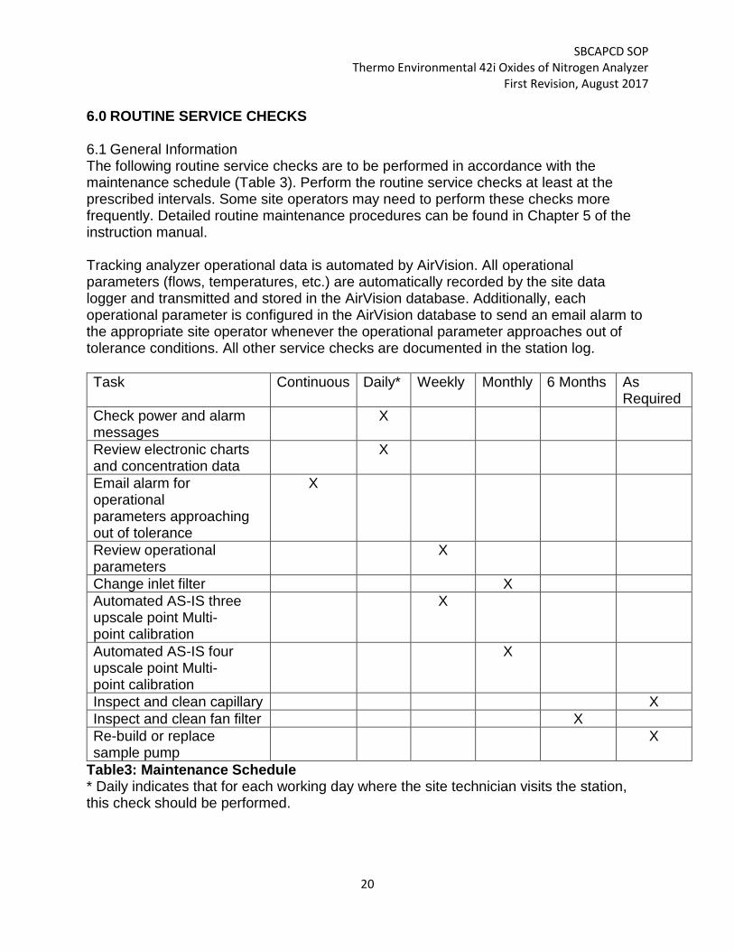
6.0 ROUTINE SERVICE CHECKS 6.1 General Information The following routine service checks are to be performed in accordance with the maintenance schedule (Table 3). Perform the routine service checks at least at the prescribed intervals. Some site operators may need to perform these checks more frequently. Detailed routine maintenance procedures can be found in Chapter 5 of the instruction manual. Tracking analyzer operational data is automated by AirVision. All operational parameters (flows, temperatures, etc.) are automatically recorded by the site data logger and transmitted and stored in the AirVision database. Additionally, each operational parameter is configured in the AirVision database to send an email alarm to the appropriate site operator whenever the operational parameter approaches out of tolerance conditions. All other service checks are documented in the station log.
Task Continuous Daily* Weekly Monthly 6 Months As Required
Check power and alarm messages
X
Review electronic charts and concentration data
X
Email alarm for operational parameters approaching out of tolerance
X
Review operational parameters
X
Change inlet filter X
Automated AS-IS three upscale point Multi- point calibration
X
Automated AS-IS four upscale point Multi- point calibration
X
Inspect and clean capillary X
Inspect and clean fan filter X
Re-build or replace sample pump
X
Table3: Maintenance Schedule * Daily indicates that for each working day where the site technician visits the station, this check should be performed.

SBCAPCD SOP Thermo Environmental 42i Oxides of Nitrogen Analyzer
First Revision, August 2017
21
6.2 Daily (or Each Visit) Checks Daily (or each site visit) review instrument diagnostic and concentration data, automated calibration values and electronic charts for any indication of analyzer malfunction. Check the instruments for any error/fault messages. 6.3 Weekly Checks In AirVision, retrieve and review the hourly operational parameters for the oxides of nitrogen analyzer, noting any unexpected shifts, indications of invalid data, and/or trends to watch. Validate the automated multi-point calibration in the AirVision database. 6.4 Monthly Checks Change the particulate filter located inside the instrument and document in the site log. Validate the automated 4 upscale point multi-point calibration in the AirVision database 6.5 Six Month Checks Inspect and clean the chassis fan filter following the procedure outlined in Chapter 5 of the instrument manual and document in the site log. 6.6 As Required Checks A common cause of a drop in sample flow below the nominal 0.7 l/m is plugging of the flow control capillary. Inspect and clean the instrument flow control capillary following the procedure outlined in Chapter 5 of the instrument manual. Document in the site log. Another common cause of a drop in sample flow and/or instable flow is the sample pump failing. Re-build or replace the sample pump when operational parameters indicate a loss of sample flow not attributed to restrictions to flow. Follow the procedures outlined in Chapter 5 of the instrument manual and document in the site log.

SBCAPCD SOP Thermo Environmental 42i Oxides of Nitrogen Analyzer
First Revision, August 2017
22
7.0 MAINTENANCE AND PROCEDURES
7.1 General Information The instrument is designed to operate unattended for long periods of time. Other than the routine service checks outlined in section 6.0 of this SOP, the 42i need very little maintenance. However, preventative maintenance requirements may vary from instrument to instrument, thus operators should refer to the instrument instruction manual to become familiar with maintenance requirements. If station operators cannot repair an instrument using procedures stated in the instruction manual, contact the IT/Monitoring Supervisor.

SBCAPCD SOP Thermo Environmental 42i Oxides of Nitrogen Analyzer
First Revision, August 2017
23
8.0 TROUBLESHOOTING
8.1 General Information The 42i has been designed to rapidly detect possible problems and allow for their quick evaluation and repair. During operation, the analyzer continuously performs self-test diagnostics and provides the ability to monitor the key operating parameters of the instrument without disturbing monitoring operations. Any diagnostic parameters which drift outside of the acceptable range will cause AirVision software to generate an alert to be emailed to the site operator. Should instrument malfunctions occur and troubleshooting is required to determine the problem, operators should refer to Chapter 6 of the instrument manual and/or consult with the Thermo Environmental customer service personnel.

SBCAPCD SOP Thermo Environmental 42i Oxides of Nitrogen Analyzer
First Revision, August 2017
24
9.0 QUALITY CONTROL/QUALITY ASSURANCE Quality control checks are performed as outlined in Section 5.0 of this SOP as well as the Santa Barbara County APCD Gas Pollutant Quality Assurance Project Plan. The results of these checks are used in validating data from oxides of nitrogen analyzers. The procedures for handling data associated with out of tolerance quality control checks are outlined in detail in Section 6 of the SBCAPCD Data Review and Validation SOP. In general, whenever data is bracketed in time by one or more calibration checks outside of allowable tolerances (zero <+/-3.1 ppb, span points <+/-10.1%, 1-pt QC <+/-15.1% CE 96-104%), that data must be invalidated and corrective action to bring the analyzer back into tolerance must be taken. In addition to calibration checks being used to validate data from oxides of nitrogen analyzers, the operational parameters of the analyzer are reviewed to ensure that these variables are within operational tolerance for all valid data. Quality Assurance checks, such as annual performance audits are also utilized to assist in the validation of oxides of nitrogen data. Whenever a performance audit shows an out of tolerance condition, the issue is immediately investigated by the site operator and documented in the site log. Should this investigation show the analyzer in an out of tolerance condition, data is invalidated for the out of tolerance period.

SBCAPCD SOP Thermo Environmental 42i Oxides of Nitrogen Analyzer
First Revision, August 2017
25
10.0 REFERENCES
Primary Quality Assurance Organization (PQAO) website http://www.arb.ca.gov/aaqm/qa/qa.htm
SBCAPCD Data Review and Validation SOP, First Revision
40 CFR 50 Appendix F
Thermo Environmental model 42i Oxides of nitrogen analyzer operation manual
“EPA Traceability Protocol for Assay and Certification of Gaseous Calibration Standards”, May 2012 (EPA/600/R-12/531
SBCAPCD Gas Pollutants QAPP, First Revision.
SBCAPCD TAPI T700/700E Dilution Calibration System, First Edition
CARB Corrective Action Notification (CAN) SOP - https://www.arb.ca.gov/aaqm/qa/pqao/can/can_sop.pdf

SBCAPCD SOP Thermo Environmental 42i Oxides of Nitrogen Analyzer
First Revision, August 2017
26
Appendix A – Example Calibration Form