standard free-standing 30” electric range · standard free-standing 30” electric range 2005. g...
TRANSCRIPT

g GE Consumer & Industrial Technical Training
Standard Free-standing 30” Electric Range
2005

g Electric Range

(GE Confidential & Proprietary Information - Not for Public Disclosure)

(GE Confidential & Proprietary Information - Not for Public Disclosure)

g Installation Issues
• Anti-Tip Device IMPORTANT – has to be installed with any new range – make sure if any floor work done that Anti-Tip Device is reinstalled
• Upper cabinets need to be at a minimum 30”above cooktop
• Separate 40 Amp circuit required (electric), separate 20 Amp circuit required (gas)
(GE Confidential & Proprietary Information - Not for Public Disclosure)

g Major Component Locations
Plug-in Surface Element(1 of 4)
Surface Element Receptacle
Thermo-Bulb
Infinite Switch (Element Control - 1 of 4)
Oven SelectorOven ThermostatOven Heating Indicator
Surface Heating Indicator
Broil Element
Electrical Terminal Block(Back of Range)
Bake Element
(GE Confidential & Proprietary Information - Not for Public Disclosure)

g Oven Door
• Stain around door - check gasket for torn areas• Check for correct door tension• Broil position different in electric oven than gas
(GE Confidential & Proprietary Information - Not for Public Disclosure)

g Baking Problems• Pre-heating is normally 15 minutes to reach 350o
• Only need to pre-heat for short baking times (cookies, rolls, biscuits, etc.)
(GE Confidential & Proprietary Information - Not for Public Disclosure)

g Bake Operation
L1
OVEN INDICATOR
OVEN SET SWITCH OFF
L1
BK
PL
BR
N
BAKE ELEMENT
BROIL ELEMENT
N
L2OVEN
THERMOSTATOFF
1
23
When the range is plugged in, line voltage from the L1side of the line is available to the Oven Set Switch, which creates a potential circuit for the Oven “On” indicator. The oven thermostat also closes a contact to provide a completed circuit to the L2 side of the line.
(GE Confidential & Proprietary Information - Not for Public Disclosure)

g Bake Operation
L1
OVEN INDICATOR
OVEN SET SWITCH BAKE
L1
BK
PL
BR
N
BAKE ELEMENT
BROIL ELEMENT
N
L2OVEN
THERMOSTATON
1
23
When the Oven Set Switch is set to BAKE & the Oven Thermostat is turned to a selected temperature, current flows from L1, through Oven Set Switch contact PL to the Oven Indicator, then through Oven Thermostat contacts 2 to 1 to the L2 side of the line.
(GE Confidential & Proprietary Information - Not for Public Disclosure)

L1
OVEN INDICATORL1
BK
PL
BR
N
BAKE ELEMENT
BROIL ELEMENT
N
L2
1
23
g Bake Operation
OVEN SET SWITCH BAKE
OVEN THERMOSTAT
ON
At the same time current flows from the L1 side of the line through Oven Set Switch contacts L1 to BK, through the Bake Element, to the Oven Thermostat contacts 2 to 1 to the L2 side of the line.
(GE Confidential & Proprietary Information - Not for Public Disclosure)

g Bake Operation
L1
OVEN INDICATORL1
BK
PL
BR
N
BAKE ELEMENT
BROIL ELEMENT
N
L2
1
23
OVEN SET SWITCH BAKE
OVEN THERMOSTAT
ON
During the BAKE function, the Broil Element is also activated. Current flows through Oven Thermostat contacts 1 to 3, through the Broil Element to Oven Set Switch contact BR to N to the neutral side of the line. The Broil Element operates at half power (120VAC) during this time.
(GE Confidential & Proprietary Information - Not for Public Disclosure)

g Testing Bake Element• Set the ohmmeter to the Rx1 scale
(GE Confidential & Proprietary Information - Not for Public Disclosure)
• Remove the oven racks & the bake element
• Touch the meter leads to the terminal connectors of the bake element
• The meter should indicate 24Ω

g Removing Bake Element
• Unplug the range• Remove the lower oven
racks• Remove the Phillips screws
from the bake element bracket, pull the element forward, & disconnect the wire connectors from the terminals
BAKE ELEMENT
WIRECONNECTORS
PHILLIPS SCREW (2)MOUNTINGBRACKET
(GE Confidential & Proprietary Information - Not for Public Disclosure)

• Remove the rear panel from the range by removing the mounting screws.
g Removing Rear PanelREAR PANEL
IMPORTANT NOTE: When moving the range backinto place, make sure that the rear foot engages in theanti-tip bracket. Check to make sure that it is engagedproperly by pulling forward on the top of the range.The anti-tip bracket must be installed.
(GE Confidential & Proprietary Information - Not for Public Disclosure)

Check wire connections to Bake Element (use high temp connectors to repair) – use Ohmmeter to check resistance value of element – Use
Voltmeter to check for 240VAC
(GE Confidential & Proprietary Information - Not for Public Disclosure)

g Broil Operation
L1
OVEN INDICATORL1
BK
PL
BR
N
BAKE ELEMENT
BROIL ELEMENT
N
L2OVEN
THERMOSTATON
1
23
OVEN SET SWITCH BROIL
When the Oven Set Switch & the Oven Thermostat are set to BROIL, current flows from L1, through Oven Set Switch contact PL to the Oven Indicator, & finally through Oven Thermostat contacts 2 & 1 & the L2 side of the line. The Bake Element does not operate during this time.
(GE Confidential & Proprietary Information - Not for Public Disclosure)

g Broil Operation
L1
OVEN INDICATORL1
BK
PL
BR
N
BAKE ELEMENT
BROIL ELEMENT
N
L2OVEN
THERMOSTATON
1
2
3
OVEN SET SWITCH BROIL
Current also flows from the L1 side of the line through Oven Set Switch contact BR, through the Broil Element, & finally through Oven Thermostat contacts 3 & 1 & the L2 side of the line. The Broil Element operates at full power during this time.
(GE Confidential & Proprietary Information - Not for Public Disclosure)

g Testing Broil Element• Set the ohmmeter to the Rx1 scale
(GE Confidential & Proprietary Information - Not for Public Disclosure)
• Remove the oven racks & the broil element• Touch the meter leads to the terminal connectors of the broil element• The meter should indicate 17Ω

g Removing Broil Element
• Unplug the range• Remove the oven racks• Remove the rear panel from the range• From behind the range, disconnect the
wire connectors from the broil element terminals
• From inside the oven, remove the Phillips screws from the brackets at the top of the broil element & from the mounting brackets, then pull the element forward so that the flag terminals clear the holes, & remove it
BROIL ELEMENT TERMINAL
BACK OF RANGE
WIRECONNECTOR
BRACKETBROIL
ELEMENT
TOP BRACKET
PHILLIPSSCREW
TOP BRACKET
PHILLIPSMACHINE
SCREW (2)
(GE Confidential & Proprietary Information - Not for Public Disclosure)

g Cooking Problems• Check sensor (1100Ω at room temp) & sensor connections – use
Ohmmeter across sensor connections – also check sensor connector plug for discoloration due to high heat – replace if necessary
• Dark baking pans retain more heat than shiny ones - reduce temp 25o
• Incorrect rack positions - see Use & Care Manual• Opening oven door many times – temperature lowered by 30o each time
door is opened• Covering oven vent (under right rear element) will effect bake – do not
leave tea pot or any pan on right rear element when oven is on, also no burner covers – oven will short cycle & effect length of bake cycle
(GE Confidential & Proprietary Information - Not for Public Disclosure)

• Remove the rear panel from the range by removing the mounting screws.
g Removing Rear PanelREAR PANEL
IMPORTANT NOTE: When moving the range backinto place, make sure that the rear foot engages in theanti-tip bracket. Check to make sure that it is engagedproperly by pulling forward on the top of the range.The anti-tip bracket must be installed.
(GE Confidential & Proprietary Information - Not for Public Disclosure)

Pilot Light for Surface UnitsOven Cycle Light
Oven Thermostat
(GE Confidential & Proprietary Information - Not for Public Disclosure)

g Testing Oven Thermostat• Set the ohmmeter to the Rx1K scale• Turn the oven thermostat to OFF• Touch the meter leads to the following terminals. The meter
should indicate as follows:
Switch Position Terminals ResistanceOff 1 - 2 Infinite (open)Off 1 - 3 Infinite (open)Off 2 - 3 Infinite (open)
3 2
4 1
Oven ThermostatTerminals
Oven Thermostat Off
14
2 3
(GE Confidential & Proprietary Information - Not for Public Disclosure)

• Turn the oven thermostat to 375o
• Remove the jumper wire from thermostat terminal 1
• Touch the meter leads to the following terminals. The meter should indicate as follows:
g Testing Oven Thermostat
1Jumper wire
3 2
4 11
4
32
Oven Thermostat On
Switch Position Terminals ResistanceOn 1 - 2 0Ω (closed)On 3 - 4 0Ω (closed)
(GE Confidential & Proprietary Information - Not for Public Disclosure)

• Touch the meter leads to the following terminals. The meter should indicate as follows:
Switch Position Terminals ResistanceOn 1 - 2 0Ω (closed)On 3 - 4 0Ω (closed)
g Testing Oven Thermostat
3 2
4 1
Oven ThermostatTerminals
1
4
32
Oven Thermostat On
(GE Confidential & Proprietary Information - Not for Public Disclosure)

g Calibration Procedures• Tools needed
– Digital Temperature tester-GE Part # WX5X603• Empty all items from oven except racks
– Have one rack at mid height inside oven• Place thermocouple on center oven rack in middle &
close oven door• Heat oven to 375o & allow to cycle at least 3 times• Allow oven to cycle
– Record temperature when oven cycles on– Record highest temperature after heat cycles off -
add the temperatures & divide by 3– Mean temperature should be within 5o of oven set
point– Make adjustments from back of bake knob or ERC
(GE Confidential & Proprietary Information - Not for Public Disclosure)

g Test Equipment WX5X603Volts-Ohms-Temp-Hz
• AC/DC Voltage• Resistance• Diodes• Capacitance• Temperature• Hi Temp Lead• Frequency in Hertz• Amps-Bypass Circuits• Auto Ranging• Auto Shut Off•Data Hold Feature• 90o Leads with sharp tips
(GE Confidential & Proprietary Information - Not for Public Disclosure)

(GE Confidential & Proprietary Information - Not for Public Disclosure)

• Unplug the range
g Removing Oven Thermostat
RED
BLACKBLUE
RED
3 2
4 1
Oven Thermostat& Wire Colors
• Remove the rear panel from the range
• Remove all of the wires from the oven thermostat terminals
(GE Confidential & Proprietary Information - Not for Public Disclosure)

• Unplug the range• Remove the rear panel from the range• Remove all of the wires from the oven
thermostat terminals
g Removing Oven Thermostat
RED
BLACKBLUE
RED
3 2
4 1
Oven Thermostat& Wire Colors
OVENTHERMOSTAT
CONTROLPANEL
PHILLIPS SCREW (2)
CONTROLKNOB
• Remove the control knob & the two Phillips screws from the thermostat
(GE Confidential & Proprietary Information - Not for Public Disclosure)

• Unplug the range• Remove the rear panel from the range• Remove all of the wires from the oven
thermostat terminals• Remove the control knob & the two
Phillips screws from the thermostat
g Removing Oven Thermostat
RED
BLACKBLUE
RED
3 2
4 1
Oven Thermostat& Wire Colors
OVENTHERMOSTAT
CONTROLPANEL
PHILLIPS SCREW (2)
CONTROLKNOBCAPILLARY TUBE
CLIPHOLEIN LINER
THERMO-BULB
• Unclip the thermo-bulb from oven liner• From rear of unit, pull the thermo-bulb & capillary tube through oven liner, & unclip it from rear panel
(GE Confidential & Proprietary Information - Not for Public Disclosure)

• Remove the rear panel from the range by removing the mounting screws.
g Removing Rear PanelREAR PANEL
IMPORTANT NOTE: When moving the range backinto place, make sure that the rear foot engages in theanti-tip bracket. Check to make sure that it is engagedproperly by pulling forward on the top of the range.The anti-tip bracket must be installed.
(GE Confidential & Proprietary Information - Not for Public Disclosure)
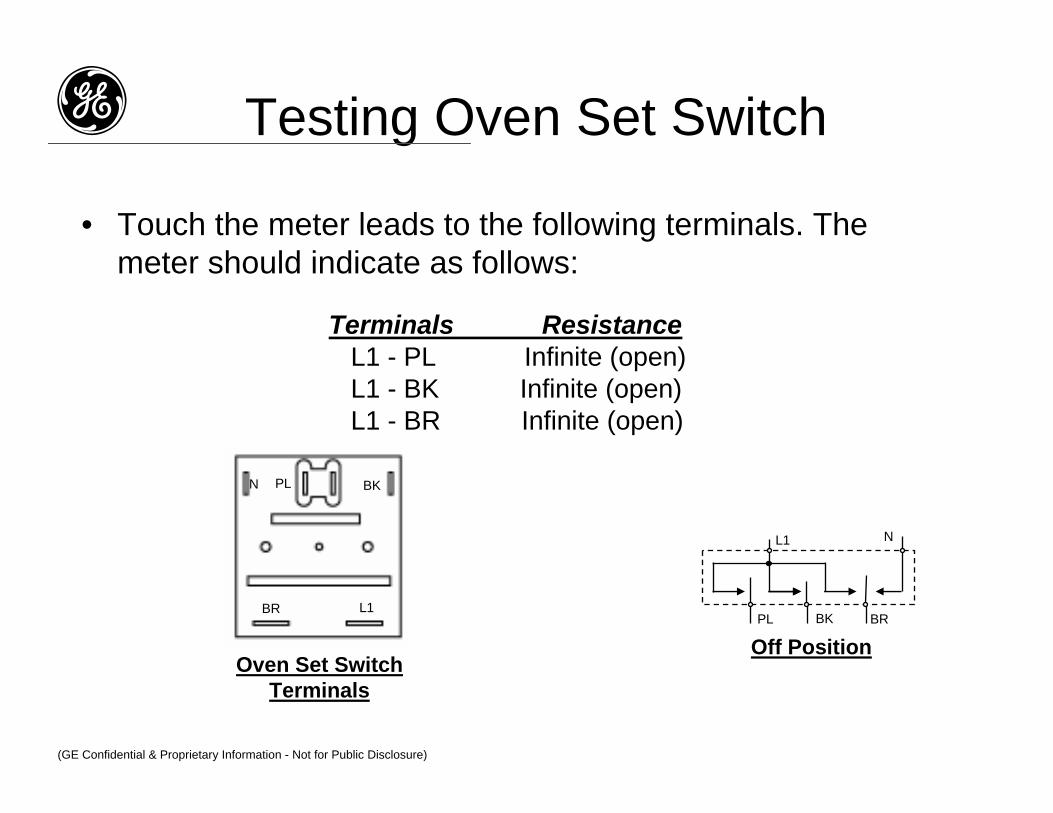
• Touch the meter leads to the following terminals. The meter should indicate as follows:
Terminals ResistanceL1 - PL Infinite (open)L1 - BK Infinite (open)L1 - BR Infinite (open)
g Testing Oven Set Switch
PL BK
L1BR
Oven Set SwitchTerminals
L1 N
Off PositionPL BK BR
N
(GE Confidential & Proprietary Information - Not for Public Disclosure)

• Turn the oven set switch to the following positions & touch the meter leads to the terminal connectors as shown below. The meter should indicate as follows:
Switch Position Terminals ResistanceBake L1 - PL 0Ω (closed)Bake L1 - BK 0Ω (closed)Bake N - BR 0Ω (closed)Broil L1 - PL 0Ω (closed)Broil L1 - PL 0Ω (closed)
g Testing Oven Set Switch
PL BK
L1BR
N
Oven Set Switch Terminals
L1 N
L1 N
PL BK BR
Bake Position
Broil Position
PL BK BR
(GE Confidential & Proprietary Information - Not for Public Disclosure)

• Unplug the range & remove the rear panel• Remove all of the wires from the oven selector terminals• Remove the control knob & the two Phillips screws from
the oven set switch
g Removing Oven Set Switch
OVEN SET SWITCH
CONTROL PANEL
PHILLIPS SCREW (2)
CONTROL KNOB
BLACK (INDICATOR)REDWHITE
BLACKBLUE
PN BK
L1BR
L
(GE Confidential & Proprietary Information - Not for Public Disclosure)

g Electric Surface Unit Problems
• Plug-in CalrodTM elements must be fully seated in receptacle
• If elements are not responding correctly to switch setting, check to see if seated properly – if damaged replace element & receptacle together
• Replace surface unit switches like for like -current sensitive & voltage sensitive – test by putting Voltmeter (AC scale) into receptacle & read voltage – on HIGH should read 240VAC 100% of time, on MED or “5” should read 240VAC 50% of time (switch cycles on & off)
(GE Confidential & Proprietary Information - Not for Public Disclosure)

• Set the ohmmeter to the Rx1 scale• With the element removed, touch the meter leads of
the ohmmeter to the ends of the prongs• The meter should indicate the following resistance
for the indicated element:8” element = 27Ω6” element = 45Ω
g Testing Plug-In Element
INFINITE SWITCH
ELEMENT
(GE Confidential & Proprietary Information - Not for Public Disclosure)

g Testing Plug-In Receptacle
• Visually inspect the receptacle for the following defects:– Cracked block– Melted block– Internal arcing (carbon buildup around
terminals)– Burnt or charred wires– Loose connectors
(GE Confidential & Proprietary Information - Not for Public Disclosure)

g Removing Plug-In Receptacle• Unplug the range• Remove the surface element from the receptacle• Remove the screw from the receptacle you wish to
service, unhook it from the cooktop, & remove it• Cut the two wires approximately 2”-3” from the edge of
the receptacle• Use the Receptacle Kit (WB17X5091) & follow the
instructions contained in the kitCOOKTOP
RECEPTACLESCREW
RECEPTACLE
CUT WIRES HERE
2” - 3”
(GE Confidential & Proprietary Information - Not for Public Disclosure)

g Surface Unit Replacements
WB17X5091WB30M2
Both parts MUST be replaced if receptacle or burner connections are damaged
(GE Confidential & Proprietary Information - Not for Public Disclosure)

(GE Confidential & Proprietary Information - Not for Public Disclosure)

• Remove the rear panel from the range by removing the mounting screws.
g Removing Rear PanelREAR PANEL
IMPORTANT NOTE: When moving the range backinto place, make sure that the rear foot engages in theanti-tip bracket. Check to make sure that it is engagedproperly by pulling forward on the top of the range.The anti-tip bracket must be installed.
(GE Confidential & Proprietary Information - Not for Public Disclosure)

Set switch on HIGH - Check for 240VAC output
Check for 240VAC input
(GE Confidential & Proprietary Information - Not for Public Disclosure)

g Electric Range Switches
(GE Confidential & Proprietary Information - Not for Public Disclosure)
The difference betweenPKTMP003.exe these 2 switches is the position of the small heater in the circuit
The heater is in parallel with the element The heater is in series with the element

Range Surface Unit Schematic
(GE Confidential & Proprietary Information - Not for Public Disclosure)
To check switch: set voltmeter on VAC, place meter leads inside receptacle, turn switch to HIGH –should read constant 240VAC. Turn switch to “5” – should read 240VAC for half the time.
Make sure that you have 240VAC at L1 & L2

• Set the ohmmeter to the Rx1 scale• With no power applied, disconnect the wires from the
infinite switch terminals. Turn the infinite switch to the “HI” setting, & you should obtain continuity readings between the following terminals:
L1 & PL1 & H1L2 & H2
g Testing Infinite Switch
H1
P
L1H2
L2
H1
P
L1
H2
L2
(GE Confidential & Proprietary Information - Not for Public Disclosure)

H2 L2 L1
H1
P
INFINITE SWITCH
CONTROL PANEL
PHILLIPS SCREW (2)
CONTROL KNOB
• Unplug the range & remove the rear panel• Remove all of the wires from the infinite switch terminals• Remove the control knob & the two Phillips screws from
the switch
g Removing Infinite Switch
(GE Confidential & Proprietary Information - Not for Public Disclosure)