standard details and detail specifications
TRANSCRIPT

STANDARD DETAILS AND
DETAIL SPECIFICATIONS

[THIS PAGE LEFT INTENTIONALLY BLANK]


APPENDICES

[THIS PAGE LEFT INTENTIONALLY BLANK]

APPENDIX 1
CRITERIA FOR THE SEPARATION OF WATER MAINS AND SANITARY SEWERS

[THIS PAGE LEFT INTENTIONALLY BLANK]

State of California Department of Health Services
M e m o r a n d u mDate: April 14, 2003 (Revised Date: October 16, 2003) To: Regional and District Engineers From: David P. Spath, Ph.D., Chief (Original signed by Dave) Drinking Water and Environmental Management
601 North 7th Street, MS 216 Sacramento, CA 95814 (916) 322-2308
Subject: GUIDANCE MEMO NO. 2003-02: GUIDANCE CRITERIA FOR THE SEPARATION OF WATER MAINS AND NON-POTABLE PIPELINES
The purpose of this memo is to update guidance dated April 5, 1983 for consistency with proposed 2003 regulations. Should there be any modification to the proposed Water Works Standards that may impact the content of this guidance, the guidance will be amended accordingly.
GUIDANCE: CRITERIA FOR THE SEPARATION OF WATER MAINS AND NON-POTABLE PIPELINES
BACKGROUND
When buried water mains are in close proximity to non-potable pipelines, the water mains are vulnerable to contamination that can pose a risk of waterborne disease outbreaks. For example, sewers (sanitary sewer mains and sewage force mains) frequently leak and saturate the surrounding soil with sewage due to structural failure, improperly constructed joints, and/or subsidence or upheaval of the soil encasing the sewer. If a nearby water main is depressurized and no pressure or negative pressure occurs, that situation is a public health hazard that is compounded if an existing sewer is broken during the installation or repair of the water main. Further, failure of a water main in close proximity to other pipelines may disturb their bedding and cause them to fail. In the event of an earthquake or other disaster, simultaneous failure of all pipelines could occur. The most effective protection against this type of drinking water contamination is adequate construction and separation of non-potable pipelines and water mains. The Waterworks Standards (Title 22, Chapter 16, Section 64572) provide separation criteria for new construction. However, when these criteria cannot be met, the risk of contamination can be reduced by increasing the structural integrity of pipe materials and joints, and ensuring minimum separation requirements are met. Therefore, the following guidance details construction criteria for the installation of water mains and non-potable pipelines to minimize the risk of contamination of drinking water.
Do your part to help California save energy. To learn more about saving energy, visit the following web site: www.consumerenergycenter.org/flex/index.html

April 14, 2003 (Revised: October 16, 2003) Page 2 of 11 Guidance Memo No. 2003-02
DEFINITIONS
COMPRESSION JOINT - A push-on joint that seals by means of the compression of a rubber ring or gasket between the pipe and a bell or coupling.
CONTINUOUS SLEEVE - A protective tube of high-density-polyethylene (HDPE)
pipe with heat fusion joints or other non-potable metallic casing without joints into which a pipe is inserted.
DISINFECTED TERTIARY RECYCLED WATER - Wastewater that has been
filtered and subsequently disinfected in accordance with Section 60301.230, Chapter 3 (Water Recycling Criteria), Title 22, California Code of Regulations.
HOUSE LATERAL - A sewer line connecting the building drain and the sanitary
sewer main serving the street. SUPPLY LINE - Pipelines conveying raw water to be treated for drinking purposes
in accordance with Section 64572 ©, proposed Water Works Standards. WATER MAIN – Means any pipeline, except for user service lines, within the
distribution system in accordance with Section 64551.70, proposed Water Works Standards.
RATED WORKING WATER PRESSURE - A pipe classification system based on
internal working pressure of the fluid in the pipe, type of pipe material, and the thickness of the pipe wall.
SANITARY SEWER MAIN - A gravity sewer conveying untreated municipal
wastewater. SEWAGE FORCE MAIN - A pressurized sewer conveying untreated municipal
wastewater.
APPLICABILITY Note that the construction criteria presented in this document apply to house laterals that cross above a water main, but not to those house laterals that cross below a water main. Water mains or non-potable pipelines that are 24-inches in diameter or larger may pose a higher degree of public health concern because of the large volumes of flow involved. Therefore, installation of water mains or non-potable pipelines 24-inches in diameter or larger should be reviewed and approved in writing by the Department on a case-by-case basis prior to construction. In no case, should water mains and non-potable pipelines conveying sewage or other liquids be installed in the same trench.

April 14, 2003 (Revised: October 16, 2003) Page 3 of 11 Guidance Memo No. 2003-02
REGULATORY REQUIREMENTS
Any new development project in which all the underground facilities are being constructed for the first time must comply with the following regulatory requirements: Existing requirements:
Section 64630.(Title 22 CA Code of Regulations) Water Main Installation“ (c) Water mains shall be installed at least:
(1) Ten feet (3 meters) horizontally from and 1 foot (0.3 meters) higher than sanitary sewer mains located parallel to the main. (2) One foot (0.3 meters) higher than sanitary sewer mains crossing the main. (3) Ten feet (3 meters), and preferably 25 feet (7.5 meters), horizontally from sewage leach fields, cesspools, seepage pits and septic tanks.
(d) Separation distances specified in (c) shall be measured from the nearest outside edges of the facilities.
(e) Where the requirements of (c) and (d) cannot be met due to topography,
inadequate right-of-way easements, or conflicts with other provisions of these regulations, lesser separation is permissible if: (1) The water main and the sewer are located as far apart as feasible within the conditions listed above. (2) The water main and the sewer are not installed within the same trench. (3) The water main is appropriately constructed to prevent contamination of the water in the main by sewer leakage.
(f) Water mains shall be disinfected according to AWWA Standard C601-81 before being placed in service. (g) Installation of water mains near the following sources of potential contamination shall be subject to written approval by the Department on a case-by-case basis:
(1) Storage ponds or land disposal sites for wastewater or industrial process water containing toxic materials or pathogenic organisms. (2) Solid waste disposal sites. (3) Facilities such as storage tanks and pipe mains where malfunction of the facility would subject the water in the main to toxic or pathogenic contamination.
Although the following requirements have not yet been adopted, they should be within the next two years and should be used as guidance for future construction.

April 14, 2003 (Revised: October 16, 2003) Page 4 of 11 Guidance Memo No. 2003-02
Proposed requirements as of the date of this document: Section 64572. Water Main Separation
(a) New water mains and new supply lines shall not be installed in the same trench as, and shall be at least 10 feet horizontally from, and one foot vertically above, any parallel pipeline conveying:
(1) Untreated sewage, (2) Primary or secondary treated sewage, (3) Disinfected secondary-2.2 recycled water (defined in section 60301.220), (4) Disinfected secondary-23 recycled water (defined in section 60301.225), and (5) Hazardous fluids such as fuels, industrial wastes, and wastewater sludge.
(b) New water mains and new supply lines shall be installed at least 4 feet horizontally
from, and one foot vertically above, any parallel pipeline conveying: (1) Disinfected tertiary recycled water (defined in section 60301.230), and (2) Storm drainage.
(c) New supply lines conveying raw water to be treated for drinking purposes shall be
installed at least 4 feet horizontally from, and one foot vertically below, any water main. (d) If crossing a pipeline conveying a fluid listed in subsection (a) or (b), a new water
main shall be constructed perpendicular to and at least one foot above that pipeline. No connection joints shall be made in the water main within eight horizontal feet of fluid pipeline.
(e) The vertical separation specified in subsections (a), (b), and (c) is required only
when the horizontal distance between a water main and pipeline is ten feet or less. (f) New water mains shall not be installed within 100 horizontal feet of any sanitary
landfill, wastewater disposal pond, or hazardous waste disposal site, or within 25 feet of any cesspool, septic tank, sewage leach field, seepage pit, or groundwater recharge project site.
(g) The minimum separation distances set forth in this section shall be measured from
the nearest outside edge of each pipe barrel.
ALTERNATIVE CRITERIA FOR CONSTRUCTION Water Mains, and Sewers and Other Non-potable Fluid-carrying Pipelines When new water mains, new sanitary sewer mains, or other non-potable fluid-carrying pipelines are being installed in existing developed areas, local conditions (e.g., available space, limited slope, existing structures) may create a situation in which there is no alternative but to install water mains, sanitary sewer mains, or other non-potable pipelines at a distance less than that required by the regulations [existing Section 64630 (proposed Section 64572)]. In such cases, through permit action, the Department may approve

April 14, 2003 (Revised: October 16, 2003) Page 5 of 11 Guidance Memo No. 2003-02
alternative construction criteria. The alternative approach is allowed under the proposed regulation Section 64551(c):
“A water system that proposes to use an alternative to the requirements in this chapter shall demonstrate to the Department how it will institute additional mitigation measures to ensure that the proposed alternative would not result in an increased risk to public health.”
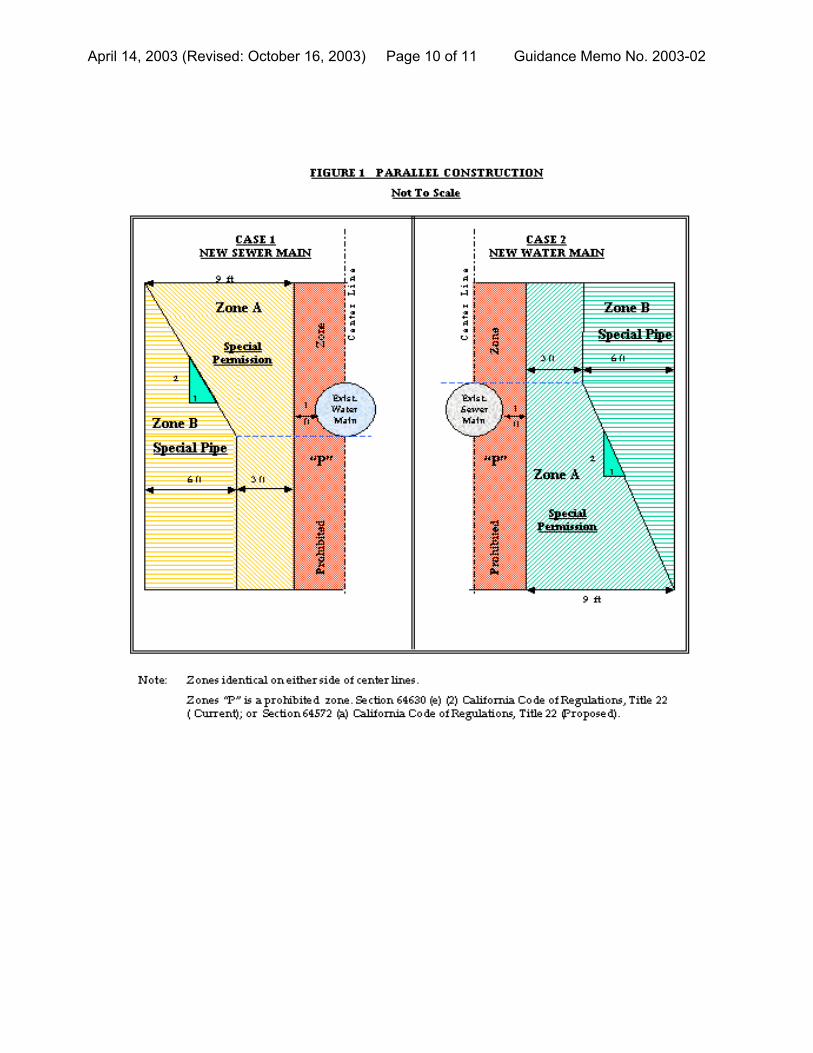
Appropriate alternative construction criteria for two different cases in which the regulatory criteria for sanitary sewer main and water main separation cannot be met are shown in Figures 1 and 2. Case 1 - New sanitary sewer main and a new or existing water main; alternative
construction criteria apply to the sanitary sewer main. Case 2 - New water main and an existing sanitary sewer main; alternative
construction criteria may apply to either or both the water main and sanitary sewer main.
Case 1: New Sanitary Sewer Main Installation (Figures 1 and 2) Zone Special Construction Required for Sanitary Sewer Main A Sanitary sewer mains parallel to water mains shall not be permitted in this zone
without prior written approval from the Department and public water system. B If the water main paralleling the sanitary sewer main does not meet the Case 2
Zone B requirements, the sanitary sewer main should be constructed of one of the following:
1. High-density-polyethylene (HDPE) pipe with fusion welded joints (per AWWA
C906-99);
2. Spirally-reinforced HDPE pipe with gasketed joints (per ASTM F-894);
3. Extra strength vitrified clay pipe with compression joints;
4. Class 4000, Type II, asbestos-cement pipe with rubber gasket joints;
5. PVC sewer pipe with rubber ring joints (per ASTM D3034) or equivalent;
6. Cast or ductile iron pipe with compression joints; or
7. Reinforced concrete pressure pipe with compression joints (per AWWA C302-95).
April 14, 2003 (Revised: October 16, 2003) Page 6 of 11 Guidance Memo No. 2003-02
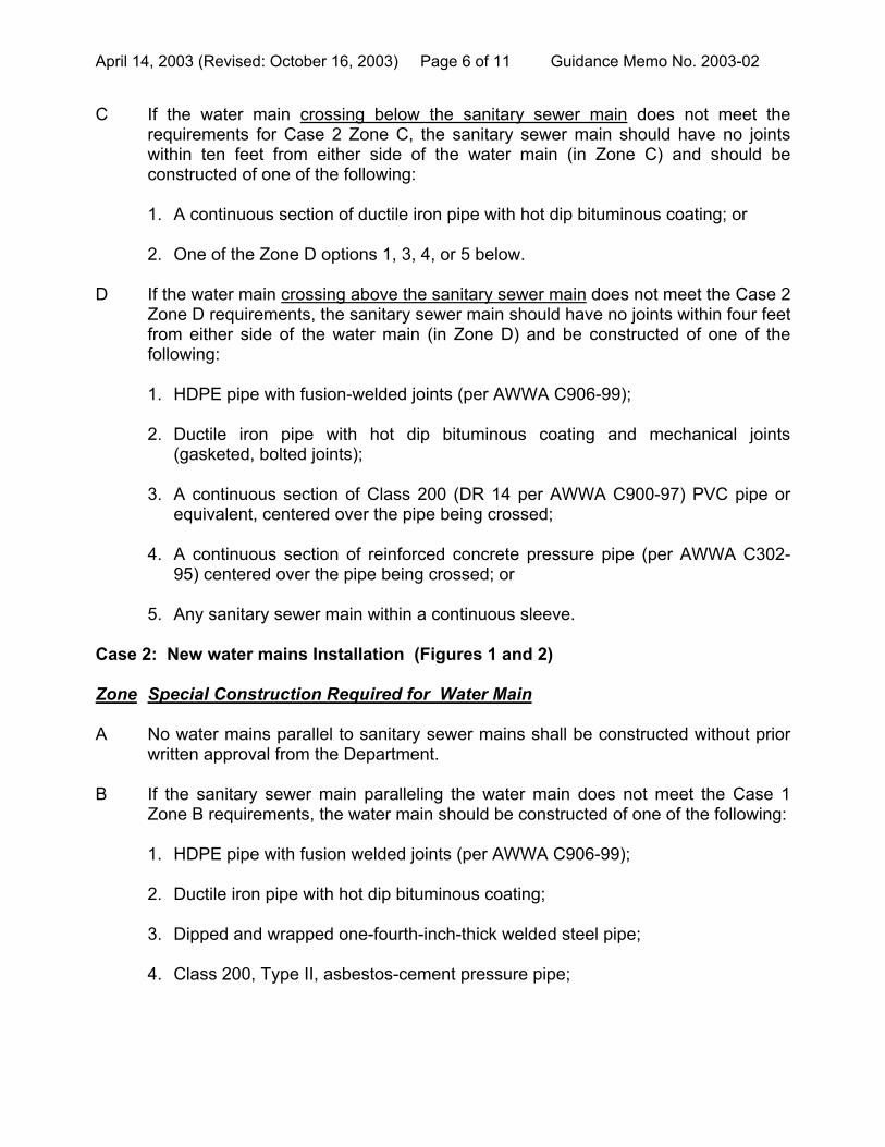
C If the water main crossing below the sanitary sewer main does not meet the requirements for Case 2 Zone C, the sanitary sewer main should have no joints within ten feet from either side of the water main (in Zone C) and should be constructed of one of the following:
1. A continuous section of ductile iron pipe with hot dip bituminous coating; or 2. One of the Zone D options 1, 3, 4, or 5 below.
D If the water main crossing above the sanitary sewer main does not meet the Case 2 Zone D requirements, the sanitary sewer main should have no joints within four feet from either side of the water main (in Zone D) and be constructed of one of the following:
1. HDPE pipe with fusion-welded joints (per AWWA C906-99); 2. Ductile iron pipe with hot dip bituminous coating and mechanical joints
(gasketed, bolted joints);
3. A continuous section of Class 200 (DR 14 per AWWA C900-97) PVC pipe or equivalent, centered over the pipe being crossed;
4. A continuous section of reinforced concrete pressure pipe (per AWWA C302-
95) centered over the pipe being crossed; or
5. Any sanitary sewer main within a continuous sleeve. Case 2: New water mains Installation (Figures 1 and 2) Zone Special Construction Required for Water Main A No water mains parallel to sanitary sewer mains shall be constructed without prior
written approval from the Department. B If the sanitary sewer main paralleling the water main does not meet the Case 1
Zone B requirements, the water main should be constructed of one of the following:
1. HDPE pipe with fusion welded joints (per AWWA C906-99); 2. Ductile iron pipe with hot dip bituminous coating; 3. Dipped and wrapped one-fourth-inch-thick welded steel pipe; 4. Class 200, Type II, asbestos-cement pressure pipe;

April 14, 2003 (Revised: October 16, 2003) Page 7 of 11 Guidance Memo No. 2003-02
5. Class 200 pressure rated PVC water pipe (DR 14 per AWWA C900-97 & C905-97) or equivalent; or
6. Reinforced concrete pressure pipe, steel cylinder type, per AWWA (C300-97 or C302-99 or C303-95).
C If the sanitary sewer main crossing above the water main does not meet the Case 1 Zone C requirements, the water main should have no joints within ten feet from either side of the sanitary sewer main (in Zone C) and be constructed of one of the following:
1. HDPE pipe with fusion-welded joints (per AWWA C906-99); 2. Ductile iron pipe with hot dip bituminous coating; 3. Dipped and wrapped one-fourth-inch-thick welded steel pipe; 4. Class 200 pressure rated PVC water pipe (DR 14 per AWWA C900-97 & C905-
97); or 5. Reinforced concrete pressure pipe, steel cylinder type, per AWWA (C300-97 or C301-99 or C303-95).
D If the sanitary sewer main crossing below the water main does not meet the requirements for Case 1 Zone D, the water main should have no joints within eight feet from either side of the sanitary sewer main (in Zone D) and should be constructed as for Zone C.
Water Mains and Pipelines Conveying Non-potable Fluids When the basic separation criteria cannot be met between water mains and pipelines conveying non-potable fluids, the requirements described above for sanitary sewer mains should apply. This includes the requirements for selecting special construction materials and the separation requirements shown in Figures 1 and 2. Note that not all construction materials allowed for sanitary sewer mains will be appropriate for other non-potable fluid lines. For example, certain plastic lines may not be appropriate for the transport of some fuel products. The selection of compatible materials of construction for non-potable fluids is a decision to be made by the project engineer. Water Mains and Sewage Force Mains Sewage force mains shall not be installed within ten feet (horizontally) of a water
main.
April 14, 2003 (Revised: October 16, 2003) Page 8 of 11 Guidance Memo No. 2003-02
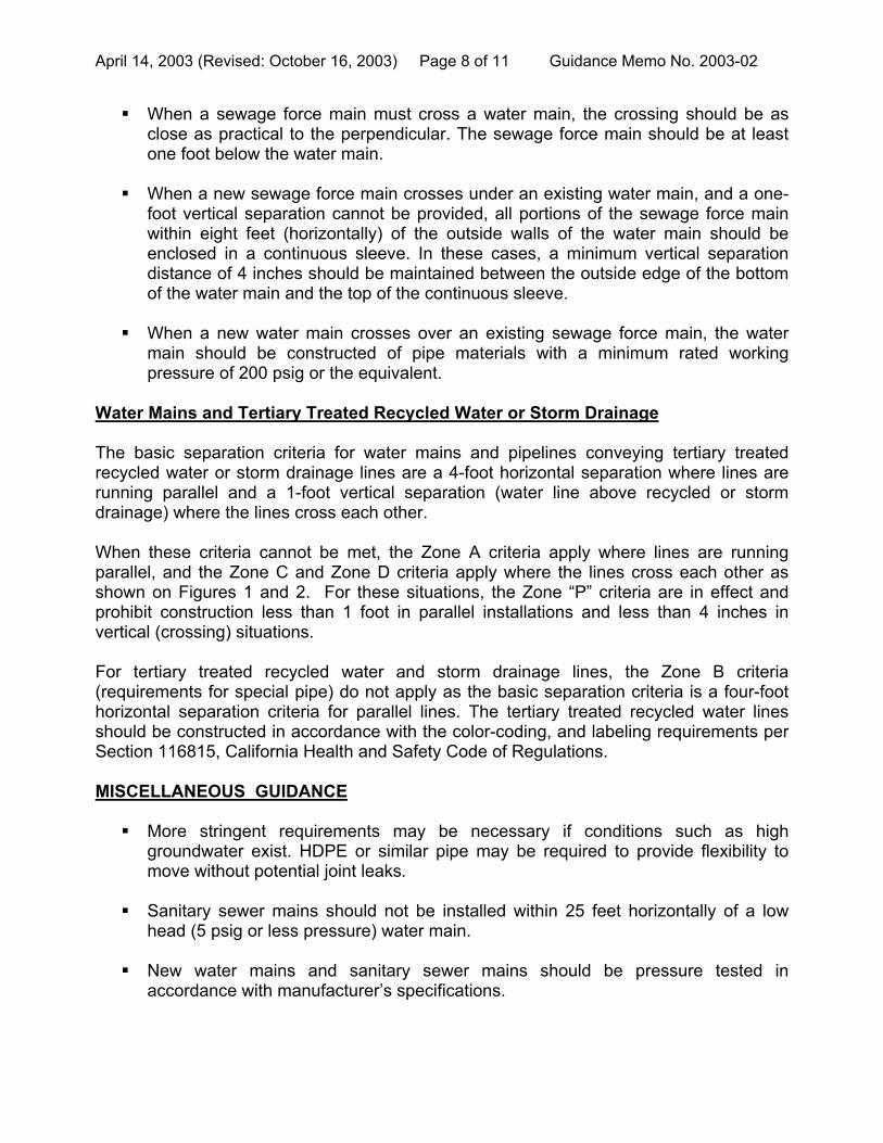
When a sewage force main must cross a water main, the crossing should be as close as practical to the perpendicular. The sewage force main should be at least one foot below the water main.
When a new sewage force main crosses under an existing water main, and a one-
foot vertical separation cannot be provided, all portions of the sewage force main within eight feet (horizontally) of the outside walls of the water main should be enclosed in a continuous sleeve. In these cases, a minimum vertical separation distance of 4 inches should be maintained between the outside edge of the bottom of the water main and the top of the continuous sleeve.
When a new water main crosses over an existing sewage force main, the water
main should be constructed of pipe materials with a minimum rated working pressure of 200 psig or the equivalent.
Water Mains and Tertiary Treated Recycled Water or Storm Drainage The basic separation criteria for water mains and pipelines conveying tertiary treated recycled water or storm drainage lines are a 4-foot horizontal separation where lines are running parallel and a 1-foot vertical separation (water line above recycled or storm drainage) where the lines cross each other. When these criteria cannot be met, the Zone A criteria apply where lines are running parallel, and the Zone C and Zone D criteria apply where the lines cross each other as shown on Figures 1 and 2. For these situations, the Zone “P” criteria are in effect and prohibit construction less than 1 foot in parallel installations and less than 4 inches in vertical (crossing) situations. For tertiary treated recycled water and storm drainage lines, the Zone B criteria (requirements for special pipe) do not apply as the basic separation criteria is a four-foot horizontal separation criteria for parallel lines. The tertiary treated recycled water lines should be constructed in accordance with the color-coding, and labeling requirements per Section 116815, California Health and Safety Code of Regulations. MISCELLANEOUS GUIDANCE More stringent requirements may be necessary if conditions such as high
groundwater exist. HDPE or similar pipe may be required to provide flexibility to move without potential joint leaks.
Sanitary sewer mains should not be installed within 25 feet horizontally of a low
head (5 psig or less pressure) water main. New water mains and sanitary sewer mains should be pressure tested in
accordance with manufacturer’s specifications.

April 14, 2003 (Revised: October 16, 2003) Page 9 of 11 Guidance Memo No. 2003-02
When installing water mains, sewers, or other pipelines, measures should be taken to prevent or minimize disturbances of existing pipelines. Disturbance of the conduit’s supporting base could eventually result in pipeline failure.
Special consideration should be given to the selection of pipe materials if corrosive
conditions are likely to exist. These conditions may be due to soil type and/or the nature of the fluid conveyed in the conduit, such as a septic sewage producing corrosive hydrogen sulfide.
NOTE: Dimensions are from the outside of the water main to the outside of the other pipeline, manhole, or sleeve.
April 14, 2003 (Revised: October 16, 2003) Page 10 of 11 Guidance Memo No. 2003-02

April 14, 2003 (Revised: October 16, 2003) Page 11 of 11 Guidance Memo No. 2003-02

[THIS PAGE LEFT INTENTIONALLY BLANK]

APPENDIX 2
RESOLUTION NO. 59,853 – N.S. REFERENCE TO OPPRESSIVE STATES STATEMENT
RESOLUTION NO. 60,382 – N.S.
AMENDMENT TO APPENDIX A OF RESOLUTION NO. 59,853 – N.S.

[THIS PAGE LEFT INTENTIONALLY BLANK]


[THIS PAGE LEFT INTENTIONALLY BLANK]


[THIS PAGE LEFT INTENTIONALLY BLANK]

APPENDIX 3
ORDINANCE NO. 6623 – N.S. CHAPTER 13.29
PROVISION OF EQUAL BENEFITS TO EMPLOYEES OF CITY CONTRACTORS

[THIS PAGE LEFT INTENTIONALLY BLANK]


[THIS PAGE LEFT INTENTIONALLY BLANK]

APPENDIX 4
THE “GREENBOOK” STANDARD SPECIFICATIONS FOR PUBLIC WORKS CONSTRUCTION
2000 EDITION
(UNDER SEPARATE COVER; NOT FURNISHED BY THE CITY)

[THIS PAGE LEFT INTENTIONALLY BLANK]

APPENDIX 5
CITY OF BERKELEY MONUMENT REFERENCING GUIDELINES

[THIS PAGE LEFT INTENTIONALLY BLANK]

1947 Center Street, 4th Floor, Berkeley, CA 94704-1155 Tel: 510.981.6400 TDD: 510.981.6903 Fax: 510.981.6390
E-mail: [email protected]
City of Berkeley
Monument Reference Guidelines
A guide to Monument Referencing in the City of Berkeley as required by the
Professional Land Surveyors’ Act (Business and Professions Code) Section
8771 et. seq.
Page 2 of 4
Department of Public Works
Engineering Division
City Monument Reference Guidelines December 1, 2009
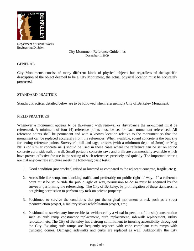
GENERAL
City Monuments consist of many different kinds of physical objects but regardless of the specific
description of the object deemed to be a City Monument, the actual physical location must be accurately
preserved.
STANDARD PRACTICE
Standard Practices detailed below are to be followed when referencing a City of Berkeley Monument.
FIELD PRACTICES
Whenever a monument appears to be threatened with removal or disturbance the monument must be
referenced. A minimum of four (4) reference points must be set for each monument referenced. All
reference points shall be permanent and with a known location relative to the monument so that the
monument can be replaced accurately from the references. When available, sound concrete is the best site
for setting reference points. Surveyor’s nail and tags, crosses (with a minimum depth of 2mm) or Mag
Nails (or similar concrete nail) should be used in those cases where the reference can be set on sound
concrete curb, sidewalk or wall. Small portable concrete saws and drills are commercially available which
have proven effective for use in the setting of such references precisely and quickly. The important criteria
are that any concrete structure meets the following basic tests:
1. Good condition (not cracked, raised or lowered as compared to the adjacent concrete, fragile, etc.);
2. Accessible for setup, not blocking traffic and preferably on public right of way. If a reference
point must be set outside the public right of way, permission to do so must be acquired by the
surveyor performing the referencing. The City of Berkeley, by promulgation of these standards, is
not giving permission to perform any task on private property;
3. Positioned to survive the conditions that put the original monument at risk such as a street
reconstruction project, a sanitary sewer rehabilitation project, etc.;
4. Positioned to survive any foreseeable (as evidenced by a visual inspection of the site) construction
such as curb ramp construction/replacement, curb replacement, sidewalk replacement, utility
relocation, etc. The City of Berkeley has a strong commitment to insuring accessibility throughout
the City. Existing curb ramps are frequently replaced with code compliant curb ramps with
truncated domes. Damaged sidewalks and curbs are replaced as well. Additionally the City

Page 3 of 4
frequently installs curb ramps at crosswalks where none currently exist, therefore those locations
shall be avoided when placing reference points;
5. The primary consideration in choosing the placement of a reference point shall be to assure its
safety and stability in perpetuity. For example, no reference point should be set near any trees with
roots likely to raise or damage the surface upon which the reference point has been set.
If no suitable concrete is available, a metal bar may be used provided that it is set flush in sound soil or
pavement. Setting metal bars has the possibility of damaging subsurface infrastructure. It shall be the duty
of the surveyor performing the referencing to assure that the site is properly evaluated for subsurface
infrastructure. Sole responsibility for any resulting damage thereto shall be borne by the surveyor
responsible for the damage. See the “REFERENCE POINTS NOT ON CONCRETE” section below for
details on this option.
QUALITY DETAILS FOR CUTTING A CROSS
The minimum depth of cut for a cross shall be 2mm. When making the cross in concrete make the initial
cut in line with the optical line of sight and the cut marking the distance at right angles to the line of sight.
This orientation helps to suggest the original location of the monument referenced and avoids the
imprecision associated with cuts at an angle to the line of sight. Paint the points for easy identification.
REFERENCE POINTS NOT ON CONCRETE
In certain places there may be no suitable concrete structure available for placing a reference point. In such
places a well described point, with a level of durability and precision equal to or exceeding that of a
minimum 2mm deep cross on sound concrete, shall be established. If a metal bar is used as a reference
point a punch shall be set in the top of the bar at the precise reference point. A plastic cap is unacceptable
for this purpose. No reference point shall be set on private property without the surveyor performing the
referencing first obtaining permission from the property owner.
DOCUMENTATION
Within two (2) weeks of the completion of any monument referencing task Corner Records for each
monument referenced shall be filed with Alameda County, and copies of the signed sealed submittals of
those Corner Records shall be provided to the City of Berkeley, Public Works Department, Engineering
Division, Survey Section.
CORNER RECORD MONUMENT AND REFERNCE POINT CONDITIONS AND DESCRIPTIONS
Corner Records shall include a detailed description of the monument referenced and reference points set:
1. Description of monument/reference material (cut cross, brass disc, brass pin, iron pin, mag nail,
rebar, etc.);
2. Character of monument/reference (cross in brick wall, cross in concrete curb, cross in concrete
sidewalk, disc in concrete, mag nail set on top of curb, nail and tag in asphalt pavement, pin in
concrete, rebar in asphalt pavement, etc.);

Page 4 of 4
3. Diameter or width of monument material;
4. Description of monument setting (inside standard casting, set flush in sidewalk, etc.);
5. Labeled with the official City of Berkeley monument designation (B####).
UNACCEPTABLE REFERENCE POINTS
In no case will lead, or any other material that may cause harm, be used in any portion of the referencing
process. Sole responsibility for the removal of such products and any harm they cause will be borne by the
surveyor responsible for using the product in the referencing process.
Scribe lines, permanent marker, paint, wood hubs, etc., due to their limited lifecycle, may not be used as a
reference point.
No reference point may be set on any fire hydrant or similarly temporary fixture.
VERTICAL REFERENCE POINTS
When a monument is to be referenced vertically, differential leveling practices shall be used. The Corner
Record shall include a minimum of four (4) vertical reference points. It is preferable that the horizontal
reference points also be used for the vertical referencing.
All vertical references shall be based on a value and datum provided by the City of Berkeley, Public
Works Department, Engineering Division, Survey Section, at the time of the request for referencing. Note
that the value associated with any control point in the City’s vertical and horizontal network is subject to
change as the City periodically recalculates its position.