stall ti over the range structi microwave oven contents general information instructions [_...
TRANSCRIPT

II
stall tistructi
Over the RangeMicrowave OvenJVM7195,JNM7196, DVM7195,PVM9195,PNM9196and PVM9215
i Questions? Call 800.GE.CARES (800.432.2737) or visitourWebsiteat: GEAppliances.com i
BEFORE YOU BEGINRead these instructions completely and carefully.
• IMPORTANT -Sovetheseinstructionsforlocolinspector'suse.
•IMPORTANT -Observeollgoverningcodesond ordinonces.
• Note to Installer - Be sure to leove theseinstructions with the Consumer.
o
o
Note to Consumer - Keepthese instructionsfor future reference.
Skill level - Installation of this appliance requires basicmechanical end electrical skills.
Proper instollation is the responsibility of the instoller.
Product failure due to improper installation is notcovered under the Warranty.
LA SECCIUN EN ESPA()OL EMPIEZA
EN LA P.GINA 25.
READ CAREFULLY.
KEEP THESE INSTRUCTIONS.
49-40702 06-13 GE
Installation
CONTENTS
General information
Instructions
[_ Recirculating .................................................19-22
Attach Mounting Plate to Wall ................19
Important SafetyInstructions ........................................3
Electrical Requirements ..................................................3
Hood Exhaust ................................................................4, 5
Damage - Shipment/Installation ..................................6
Preparation of Top Cabinet ......................19
Adapting Blowerfor Recirculation ..................................20, 21
Mount the Oven...................................21, 22
Installing the Charcoal Filter ....................22
Parts Included ...................................................................6
Tools You Will Need .........................................................7
Mounting Space ................................................................7
Step-by-step installation guide
Placement of Mounting Plate .................................. 8-10
Removing the Mounting Plate .............................8
Finding the Wall Studs..........................................8
Determining Wall Plate Location ........................9
Aligning the Wall Plate .......................................10
Installation Types ....................................................11-22
[_ Outside Top ....................................Exhaust 12-14
Attach Mounting Plate to Wall .................12
Preparation of Top Cabinet .......................13
Assemble and Install Adaptor ..................13
Mount the Oven...................................13, 14
Adjust the Exhaust Adaptor ......................14
Connecting Ductwork ................................24
[_i_ Outside .................................. 15-18Back Exhaust
Preparing Rear Wall forOutside Back Exhaust................................25
Attach Mounting Plate to Wall .......... 15, 16
Preparation of Top Cabinet .......................16
Adapting Blower for OutsideBack Exhaust ..........................................16, 17
Mount the Oven..........................................18
Before You Use Your Oven .......................................... 23
Installation Instructions
IMPORTANT SAFETY INSTRUCTIONS
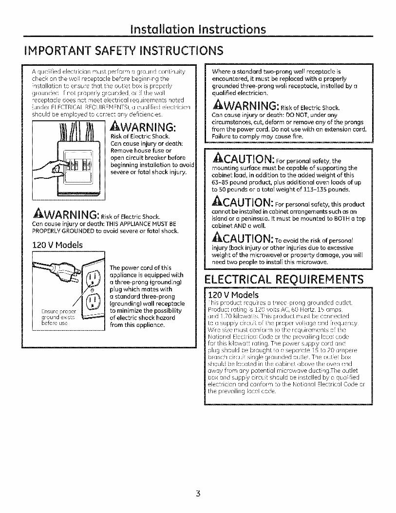
A qualified electrician must perform a ground continuitycheck on the wall receptacle before beginning theinstallation to ensure that the outlet box is properlygrounded. If not properly grounded, or if the wallreceptacle does not meet electrical requirements noted(under ELECTRICALREQUIREMENTS),a qualified electricianshould be employed to correct any deficiencies.
WARNING:Risk of Electric Shock.Can cause injury or death:Remove house fuse oropen circuit breaker beforebeginning installation to avoidsevere or fatal shock injury.
AI:lt,W_-_I_I_I I I_i _: Risk of Electric Shock.Can cause injury or death: THIS APPLIANCEMUSTBEPROPERLYGROUNDEDto avoid severe or fatal shock.
120 V Models
groond exi sbefore use
The power cord of thisappliance is equipped witha three-prong (grounding)plug which mates witha standard three-prong(grounding) wall receptacleto minimize the possibilityof electric shock hazardfrom this appliance.
Where a standard two-prong wall receptacle isencountered, it must be replaced with a properlygrounded three-prong wall receptacle, installed by aqualified electrician.
AWARN ING:RiskofElectricShock.Can cause injury or death: DO NOT,under anycircumstances, cut, deform or remove any of the prongsfrom the power cord. Do not use with an extension cord.Failure to comply may cause fire.
A,-,^, ,T,,,_t,,_IL_f_U/I_JI_I: For personal safety, themounting surface must be capable of supporting thecabinet load, in addition to the added weight of this63-85 pound product, plus additional oven loads of upto 50 pounds or a total weight of 113-135 pounds.
ACAUTION: Forpersonalsafety,thisproductcannot be installed in cabinet arrangements such as anisland or a peninsula. It must be mounted to BOTHa topcabinet AND a wall.
CAUTION: Toavoidtheriskofpersonalinjury (back injury or other injuries due to excessiveweight of the microwave) or property damage, you willneed two people to install this microwave.
ELECTRICAL REQUIREMENTS120 V ModelsThis product requires a three-prong grounded outlet.Product rating is 120 volts AC, 60 Hertz, 15 amps,and 1.70 kilowatts. This product must be connectedto a supply circuit of the proper voltage and frequency.Wire size must conform to the requirements of theNational Electrical Code or the prevailing local codefor this kilowatt rating. The power supply cord andplug should be brought to a separate lS to 20 amperebranch circuit single grounded outlet. The outlet boxshould be located in the cabinet above the oven andaway from any potential microwave ducting.The outletbox and supply circuit should be installed by a qualifiedelectrician and conform to the National Electrical Code orthe prevailing local code.
3

Installation Instructions
HOOD EXHAUSTNOTE:Read these next two pages only if you plan to vent your exhaust to the outside.If you plan to recirculate the air back into the room, proceed to page 6.
OUTSIDE TOP EXHAUST {EXAMPLE ONLY)
The following chart describes an example of one possibleductwork installation.
DUCT PIECES
BRoof Cap
12 Ft. Straight Duct(6" Round)
Rectangular-to-RoundTransition Adaptor*
EQUIVALENT NUMBER EQUIVALENT
LENGTH x USED = LENGTH
24 Ft. x (!)
12 Ft. x (!)
5 Ft. x (!)
Equivalent lengths of duct pieces are based on actual tests andreflect requirements for good venting performance with any vent hood.
Total Length
24 Ft.
12 Ft.
5 Ft.
41 Ft.
*IMPORTANT:If a rectangular-to-round transition adaptor is used, the bottom corners of the damper willhave to be cut to fit, using the tin snips, in order to allow free movement of the damper.
OUTSIDE BACK EXHAUST (EXAMPLE ONLY)
The following chart describes an example of one possibleductwork installation.
[
DUCT PIECES
DWall Cap
3 Ft. Straight Duct31A'' x !0" Rectangular)
90° Elbow
EQUIVALENT NUMBER EQUIVALENTLENGTH* x USED = LENGTH
40 Ft. x (!)
3 Ft. x (!)
10 Ft. x (2)
Equivalent lengths of duct pieces are based on actual tests andreflect requirements for good venting performance with any vent hood.
Total Length
40 Ft.
3 Ft.
20 Ft.
= 63 Ft.
NOTE: For back exhaust, care should be taken to align exhaust with space between studs, or wall should be preparedat the time it is constructed by leaving enough space between the wall studs to accommodate exhaust.
4
Installation Instructions
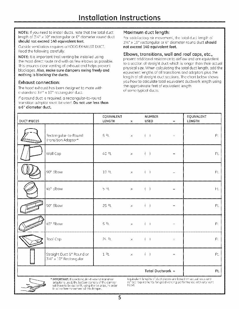
NOTE: If you need to install ducts, note that the total ductlength of 3¼" x 10" rectangular or 6" diameter round ductshould not exceed 140 equivalent feet.Outside ventilation requires a HOODEXHAUSTDUCT.Read the following carefully.
NOTE: It is important that venting be installed usingthe most direct route and with as few elbows as possible.This ensures clear venting of exhaust and helps preventblockages. Also, make sure dampers swing freely andnothing is blocking the ducts.
Exhaust connection:
The hood exhaust has been designed to mate witha standard 3½" x 10" rectangular duct.
If a round duct is required, a rectangular-to-roundtransition adaptor must be used. Do not use less thana 6" diameter duct.
Maximum duct length:
For satisfactory air movement, the total duct length of3VJ' x 10" rectangular or 6" diameter round duct shouldnot exceed 140 equivalent feet.
Elbows, transitions, wall and roof caps, etc.,present additional resistance to airflow and are equivalentto a section of straight duct which is longer than their actualphysical size. When calculating the total duct length, add theequivalent lengths of all transitions and adaptors plus thelength of all straight duct sections. The chart below showsyou how to calculate total equivalent ductwork length usingthe approximate feet of equivalent lengthof some typical ducts.
EQUIVALENT NUMBER EQUIVALENTDUCT PIECES LENGTH x USED = LENGTH
Rectangular-to-Round 5 Ft. ( ) Ft.x
Transition Adaptor*
_ Wall Cap 40 Ft. x ( ) = Ft.
(_ 90° Elbow 10 Ft. x ( ) = Ft.
/45° Elbow 5 Ft. x ( ) = Ft.
90° Elbow 25 Ft. x ( ) = Ft.
_ /45 Elbow 5Ft. x ( ) = Ft.
Roof Cap 2/4Ft. x ( ) = Ft.
Straight Duct 6" Round or 1 Ft. x ( ) = Ft.3¼" x 10" Rectangular
Total Ductwork = Ft.
* IMPORTANT:If a rectangular-to-round transition Equivalent lengths of duct pieces are based on actual tests andadaptor is used, the bottom corners of the damper reflect requirements for good venting performance with any ventwill have to be cut to fit, using the tin snips, in order hood.to allow free movement of the damper.
5
Installation Instructions
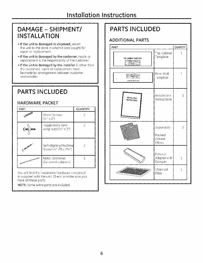
DAMAGE- SHIPMENT/INSTALLATION
• If the unit is damaged in shipment, returnthe unit to the store in which it was bought forrepair or replacement.
• If the unit is damaged by the customer, repair orreplacement is the responsibility of the customer.
• If the unit is damaged by the installer (if other thanthe customer), repair or replacement mustbe made by arrangement between customerand installer.
PARTS INCLUDED
HARDWARE PACKET
PART
Wood Screws(¼" x 2")
Toggle Bolts (andwing nuts)(¼" x 3")
Self-aligning MachineScrew (¼"-28 x 2%')
Nylon Grommet(for metal cabinets)
QUANTITY
2
You will find the installation hardware containedin a packet with the unit. Check to make sure youhave all these parts.
NOTE:Some extra parts are included.
PARTS INCLUDED
ADDITIONAL PARTS
PART
TOPCABINETTEMPLATE
I_"_=_i_IREAR W_LL_EMPLAmD
INSTAU_ATION
INSTRUCTIONS
Top CabinetTemplate
Rear WallTemplate
InstallationInstructions
Separately
PackedGreaseFilters
ExhaustAdoptor withDamper
CharcoalFilter
m
QUANTITY
i
i
i
6
Installation Instructions
TOOLS YOU WILL NEED
# i and #2 Phillips Pencilscrewdriver
Tinsnips(for cuttingdamper, if required)
Gloves
Safetygoggles
Ruleror tapemeasureand
ht edge
Scissors(to cuttemplate, if necessary)
Saw(saber,holeor keyhole)
Electric drill with VX', V_G",W' and s/8"drill bits
0Stud finderOF
IHammer(optional)
Level
Carpentersquare(optional)
¢5bFiller blocksor scrapwood pieces,if neededfor top cabinet spacing(usedon recessedbottomcabinet installationsonly)
Duct and maskingtape
MOUNTING SPACE
66" ormore fromthe floor tothe top ofthe oven
..........Bottom edge of
cabinet needs tobe 30" or more
from the cookingsurface
Backsplash
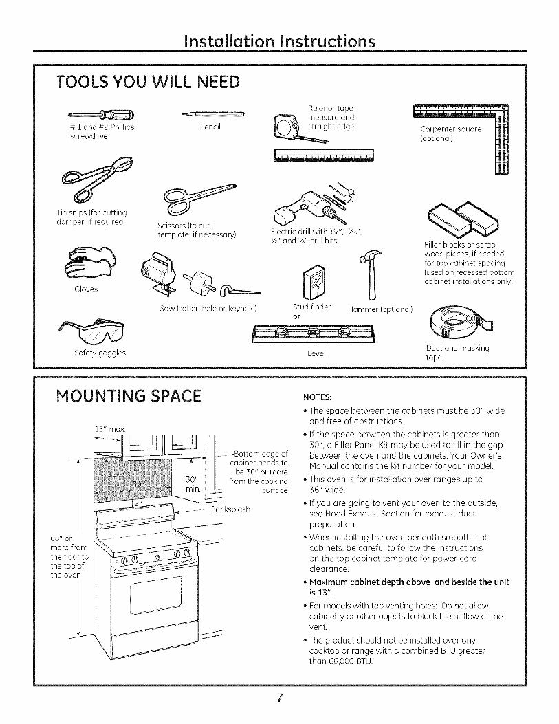
NOTES:
• The space between the cabinets must be 30" wideand free of obstructions.
• If the space between the cabinets is greater than30", a Filler Panel Kit may be used to fill in the gapbetween the oven and the cabinets. Your Owner'sManual contains the kit number for your model.
• This oven is for installation over ranges up to36" wide.
• If you are going to vent your oven to the outside,see Hood Exhaust Section for exhaust ductpreparation.
• When installing the oven beneath smooth, flatcabinets, be careful to follow the instructionson the top cabinet template for power cordclearance.
• Maximum cabinet depth above and beside the unitis 13".
. For models with top venting holes: Do not allowcabinetry or other objects to block the airflow of thevent.
. The product should not be installed over anycooktop or range with a combined BTUgreaterthan 66,000 BTU.
Instollotion Instructions
-IPLACEMENT OF THE MOUNTING PLATE
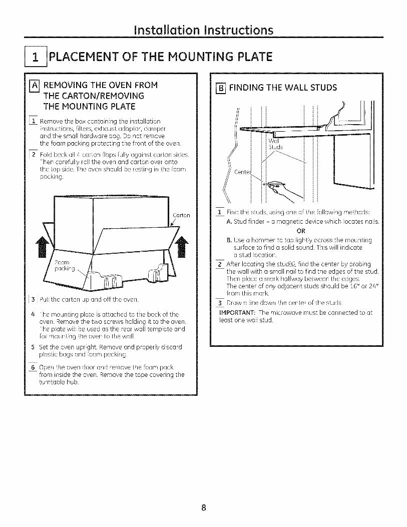
REMOVING THE OVEN FROM
THE CARTON/REMOVING
THE MOUNTING PLATE
%
[]
Remove the box containing the installationinstructions, filters, exhaust adaptor, damperand the small hardware bag. Do not removethe foam packing protecting the front of the oven.
Fold back all 4 carton flaps fully against carton sides.Then carefully roll the oven and carton over ontothe top side. The oven should be resting in the foampacking.
Foam
packing
%%
%
%
Pull the carton up and off the oven.
The mounting plate is attached to the back of theoven. Remove the two screws holding it to the oven.The plate will be used as the rear wall template andfor mounting the oven to the wall.
Set the oven upright. Remove and properly discardplastic bags and foam packing.
Open the oven door and remove the foam packfrom inside the oven. Remove the tape covering theturntable hub.
FINDING THE WALL STUDS
Cente_
WallStuds
[_ Find the studs, using one of the following methods:
A. Stud finder - a magnetic device which locates nails.OR
B. Use a hammer to tap lightly across the mountingsurface to find a solid sound. This will indicatea stud location.
[_ After locating the stud(s), find the center by probingthe wall with a small nail to find the edges of the stud.Then place a mark halfway between the edges.The center of any adjacent studs should be 16" or 24"from this mark.
[_ Draw a line down the center of the studs.IMPORTANT: The microwave must be connected to atleast one wall stud.
8
Installation Instructions
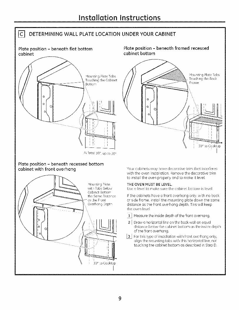
[_ DETERMINING WALL PLATE LOCATION UNDER YOUR CABINET
Plate position - beneath flat bottomcabinet
Plate position - beneath framed recessedcabinet bottom
o
MountingPlateTabsTouching the Cabinet:.Bottom
At least 30", up to 36"
Mounting Plate TabsTouching the BackFrame
II "30" to Cooktop
i ,, I
Plate position - beneath recessed bottomcabinet with front overhang
0
0
C
MountingPlatewith TabsBelowCabinetBottomthe SameDistanceasthe Front
'....Overhang Depth....-..
l
;0" to Cooktop
I
Your cabinets may have decorative trim that interfereswith the oven installation. Remove the decorative trimto instGII the oven properly and to make it level.
THE OVEN MUST BE LEVEL.Use a level to make sure the cabinet bottom is level.
If the cabinets have a front overhang only, with no backor side frame, install the mounting plate down the samedistance as the front overhang depth. This will keepthe oven level.
[_ Measure the inside depth of the front overhang.
[_ Draw a horizontal line on the back wall an equaldistance below the cabinet bottom as the inside depthof the front overhang.
[_ For this type of installation with front overhang only,align the mounting tabs with this horizontal line, nottouching the cabinet bottom as described in Step D.
9
Installation Instructions
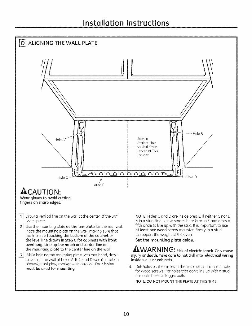
_ ALIGNING THE WALL PLATE
Hole Draw aVertical Line
b---- on Wall from
Center of TopCabinet
Hole C
ACAUTION'.Wear gloves to avoid cuttingfingers on sharp edges.
II
olo
4 TIAreaE J
I
[_ Draw a vertical line on the wall at the center of the 30"wide space.
[_ Usethe mounting plate as the template for the rear wall.Placethe mounting plate on the wall, making sure thatthe tabs are touching the bottom of the cabinet orthe level line drawn in Step C for cabinets with frontoverhang. Line up the notch and center line onthe mounting plate to the center line on the wall.
[_ While holding the mounting plate with one hand, drawcircles on the wall at holes A, B, C and D (see illustrationabove/actual plate marked with arrows). Four holesmust be used for mounting.
NOTE: Holes Cand D are inside area E.If neither C nor Dis in a stud, find a stud somewhere in area Eand draw afifth circle to line up with the stud. It is important to useat least one wood screw mounted firmly in a studto support the weight of the oven.
Set the mounting plate aside.
WA RNING:Riskofelectricshock.Cancause
injury or death. Take care to not drill into electrical wiringinside walls or cabinets.
[_ Drill holes on the circles. If there is a stud, drill a sad'holefor wood screws. For holes that don't line up with a stud,drill a %" hole for toggle bolts.NOTE:DO NOTMOUNTTHEPLATEAT THISTIME.
10

Installation Instructions
2-I INSTALLATION TYPES
This oven is designed for adaptation to the following
3 types of ventilotion:
A. Outside Top Exhaust {Vertical Duct}
B. Outside Back Exhaust {Horizontal Duct}
C. Recirculating INon-Vented Ductless}
{Choose A, B or C)
NOTE: For JVM1950, PVM1970, DVM1950, and PVM2170models. This oven is shipped assembled for Outside TopExhaust. Select the type of ventilation required for yourinstallation and proceed to that section.
NOTE: For JNMI951 ond PNMI971 models. This oven is
shipped assembled for Redrcuk]ting. Select the type of
ventilation required for your instollotion ond proceed to thotsection.
OUTSIDE TOP EXHAUST{VERTICAL DUCT1
r_ UTSIDE BACK EXHAUST{HORIZONTAL DUCT)
Adaptor in Place forOutside Top Exhaust
RECIRCULATING{NON-VENTED DUCTLESS)
A Charcoal Filter Accessory Kitis required for the non-ventedexhaust. (Seeyour Owner'sivlonuol for the kit number.)
11
Installation Instructions
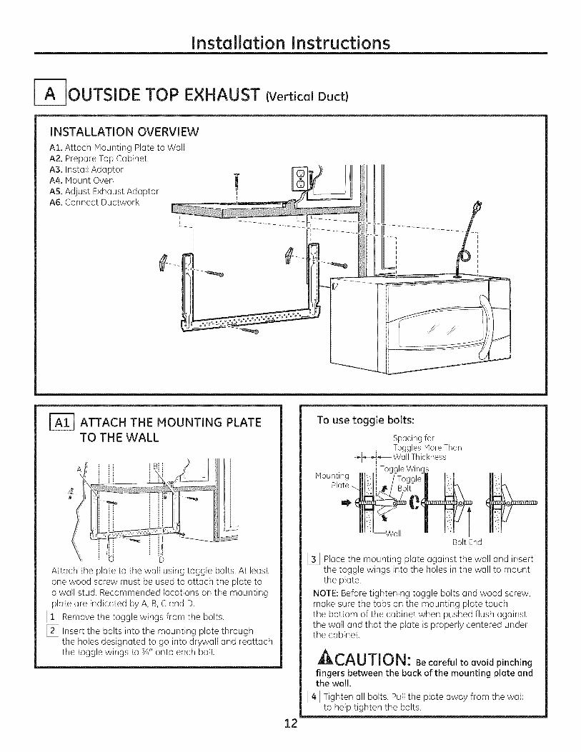
-IOUTSIDE TOP EXHAUST {Vertical Duct)
INSTALLATION OVERVIEW
A1. Attach Mounting Plate to WallA2. Prepare Top CabinetA3. Install AdaptorA4. Mount OvenAS. Adjust Exhaust AdaptorA6. Connect Ductwork
_=_ ATTACH THE MOUNTING PLATETO THE WALL
Attach the plate to the wall using toggle bolts. At leastone wood screw must be used to attach the plate toa wall stud. Recommended locations on the mountingplate are indicated by A, B,C and D.
[_ Remove the toggle wings from the bolts.
[_ Insert the bolts into the mounting plate throughthe holes designated to go into drywall and reattachthe toggle wings to ¾" onto each bolt.
12
To use toggle bolts:
Mounting
Spacing forToggles Hare Than
_-I_,-k_-- Wall Thickness
i Toggle Wing_
Bolt End
[_ Place the mounting plate against the wall and insertthe toggle wings into the holes in the wall to mountthe plate.
NOTE: Before tightening toggle bolts and wood screw,make sure the tabs on the mounting plate touchthe bottom of the cabinet when pushed flush againstthe wall and that the plate is properly centered underthe cabinet.
ACA UTI0 N: Becarefultoavoidpinching
fingers between the back of the mounting plate andthe wall.
[_ Tighten all bolts. Pull the plate away from the wallto help tighten the bolts.
Installation Instructions
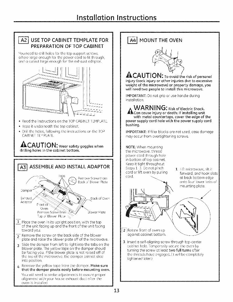
USE TOP CABINET TEMPLATE FORPREPARATION OF TOP CABINET
You need to drill holes for the top support screws,a hole large enough for the power cord to fit through,and a cutout large enough for the exhaust adaptor.
• Read the instructions on the TOPCABINETTEMPLATE.
• Tape it underneath the top cabinet.• Drill the holes, following the instructions on the TOP
CABINETTEMPLATE.
At-^, i-rir, t,iui, : Weorsofetygoggleswhendrilling holes in the cabinet bottom.
r_ ASSEMBLE AND INSTALL ADAPTOR
Da
Exhaust_q_-_Adaptor" _ "'_C_-:
Front o'f_Oven
Remove Screw
Topof Blower Plate
Tabs
_ Remove Screw fromBack of Blower Plate
¢ Back of Oven
_wer Plate
[_ Place the oven in its upright position, with the topof the unit facing up and the front of the unit facingtoward you.
[_ Remove the screw on the back side of the blowerplate and raise the blower plate off of the microwave.
[_ Slide the damper from left to right into the tabs on theblower plate. The yellow tape on the damper shouldbe facing you. If the blower plate is not raised off ofthe top of the microwave, the damper cannot slideinto position.
[_ Remove the yellow tape from the damper. Make surethat the damper pivots easily before mounting oven.You will need to make adjustments to assure properalignment with your house exhaust duct after theoven is installed.
_ MOUNT THE OVEN
CA UTI'0N:to t ,eriskofpersonal
injury (back injury or other injuries due to excessiveweight of the microwave) or property damage, youwill need two people to install this microwave.
IMPORTANT: Do not grip or use handle duringinstallation.
A WA RNING:RiskofElectricShock.Can cause injury or death: If installing unitwith metal countertops, cover the edge of the
power supply cord hole with the power supply cordbushing.
IMPORTANT: If filler blocks are not used, case damagemay occur from overtightening screws.
NOTE: When mountingthe microwave, threadpower cord through holein bottom of top cabinet.Keep it tight throughoutSteps 1-3. Do not pinchcord or lift oven by pullingcord.
[_ Lift microwave, tilt itforward, and hook slotsat back bottom edgeonto four lower tabs ofmounting plate.
[_ Rotate front of oven upagainst cabinet bottom.
[_ Insert a self-aligning screw through top-centercabinet hole. Temporarily secure the oven byturning the screw at least two full turns afterthe threads have engaged. (Itwill be completelytightened later.)
13
Installation Instructions
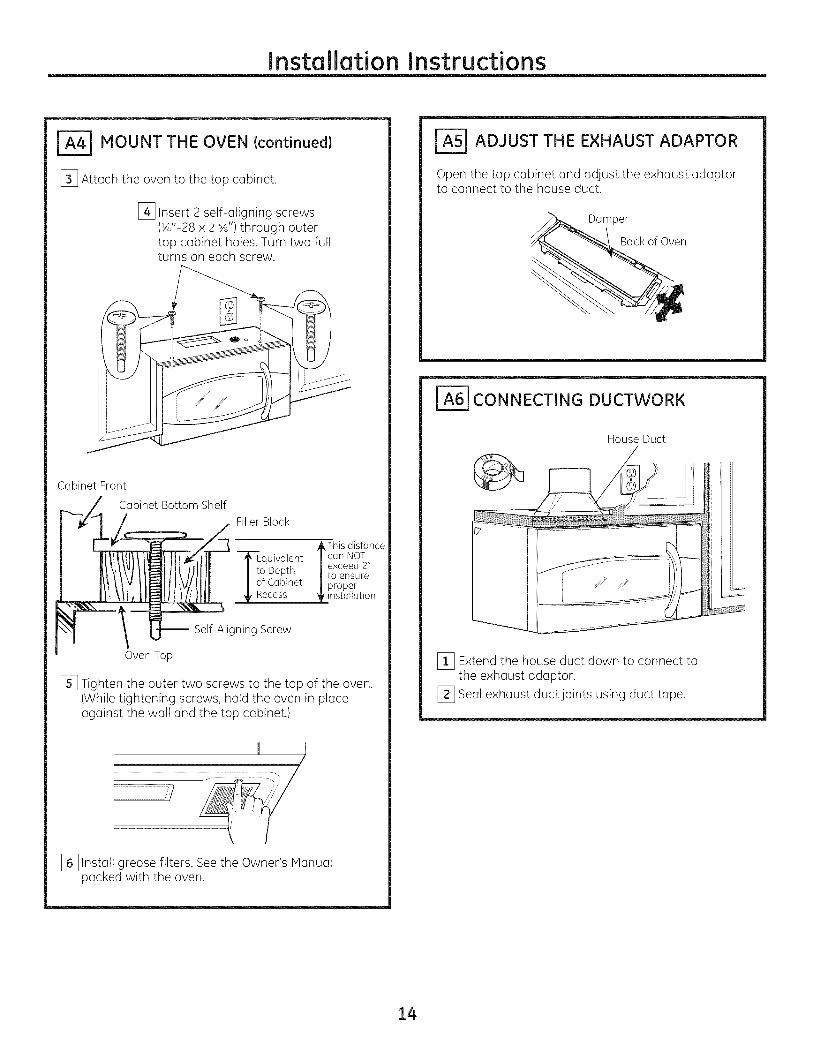
_ MOUNT THE OVEN {continued)
[_ Attach the oven to the top cabinet.
[_ Insert 2 self-aligning screws(¼"-28 x 2 sA')through outertop cabinet holes. Turn two fullturns on each screw.
Cabinet Front
Cabinet Bottom Shelf
FillerBlock
_This distance--]_Equivalent /can NOT
exceed 2"I i° Depth /to ensureI of Cabinet |proper
_installation
-- Self-Aligning Screw
Oven Top
[] Tighten the outer two screws to the top of the oven.(While tightening screws, hold the oven in placeagainst the wall and the top cabinet.)
,/..............................................................................................111 i _],
[_ Install grease filters. Seethe Owner's Manualpacked with the oven.
ADJUST THE EXHAUST ADAPTOR
Open the top cabinet and adjust the exhaust adaptorto connect to the house duct.
Damper
Back of Oven
_] CONNECTING DUCTWORK
House Duct
[_ Extend the house duct down to connect tothe exhaust adaptor.
[_ Seal exhaust duct joints using duct tape.
14
Installation Instructions
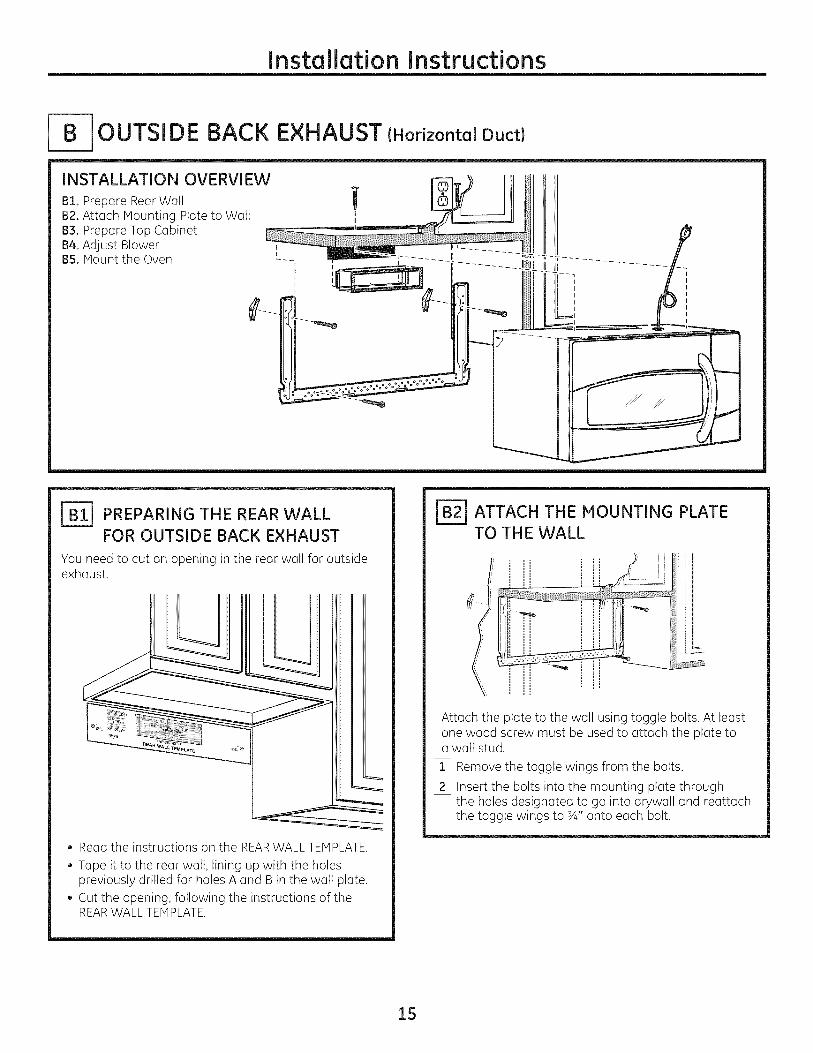
r OUTSIDE BACK EXHAUST (Horizontal Duct}
INSTALLATION OVERVIEW !B1. Prepare Rear Wall !B2. Attach Mounting Plate to Wall
B3. Prepare Top Cabinet __ _
B4. Adjust Blower l :_
BS. ivlount the Oven --- _ ,_ U_L]
J-_ PREPARING THE REAR WALLFOR OUTSIDE BACK EXHAUST
You need to cut an opening in the rear wall for outsideexhaust.
• Read the instructions on the REARWALL TEMPLATE.
• Tape it to the rear wall, lining up with the holespreviously drilled for holes A and B in the wall plate.
• Cut the opening, following the instructions of theREARWALL TEMPLATE.
ATTACH THE MOUNTING PLATETO THE WALL
: i ...........-_ iii/i j
Attach the plate to the wall using toggle bolts. At leastone wood screw must be used to attach the plate toa wall stud.
[_ Remove the toggle wings from the bolts.
[_ Insert the bolts into the mounting plate throughthe holes designated to go into drywall and reattachthe toggle wings to sA" onto each bolt.
15

Installation Instructions
To use toggle bolts:
Spacing for Toggles More-_l_-_----Than Wall Thickness
Mounting Toggle Wings
Platemj__"
Bolt End
[_ Place the mounting plate against the wall and insertthe toggle wings into the holes in the wall to mountthe plate.
NOTE: Before tightening toggle bolts and wood screw,make sure the tabs on the mounting plate touchthe bottom of the cabinet when pushed flush againstthe wall and that the plate is properly centered underthe cabinet.
CAUTI 0 N: Be careful to avoid pinchingfingers between the back of the mounting
plate and the wall.
[_ Tighten all bolts. Pull the plate away from the wallto help tighten the bolts.
] USE TOP CABINET TEMPLATEFOR PREPARATION OF TOP
CABINET
You need to drill holes for the top support screws anda hole large enough for the power cord to fit through.
• Read the instructions on the TOPCABINETTEMPLATE.
• Tape it underneath the top cabinet.• Drill the holes, following the instructions on the
TOPCABINETTEMPLATE.
_L,i_U||U|_: Wear safety goggles whendrilling holes in the cabinet bottom.
[=_ ADAPTING BLOWER FOROUTSIDE BACK EXHAUST
[_ Remove the blower motor screw that holds theblower plate to the oven. Lift the front of the blowerplate to install the blower.
Blower '___ BlowerPlateMotorScrew
...... _O_o_rscrew
[_ Carefully pull out the blower unit. The wireswill extend far enough to allow you to adjustthe blower unit.
BEFORE:Fan Blade
Openings Facing Up ___ _/End B
[_ Rotate blower unit counterclockwise 180°.
Before Rotation After Rotation
lack of ,Oven Oven
[_ Gently remove the wires from the grooves.Reroute the wires through grooves on other sideof the blower unit.
Before Rerouting After Rerouting
Wires Routed Through RightSide
Wires RoutedThroughLeftSide
16
Installation Instructions
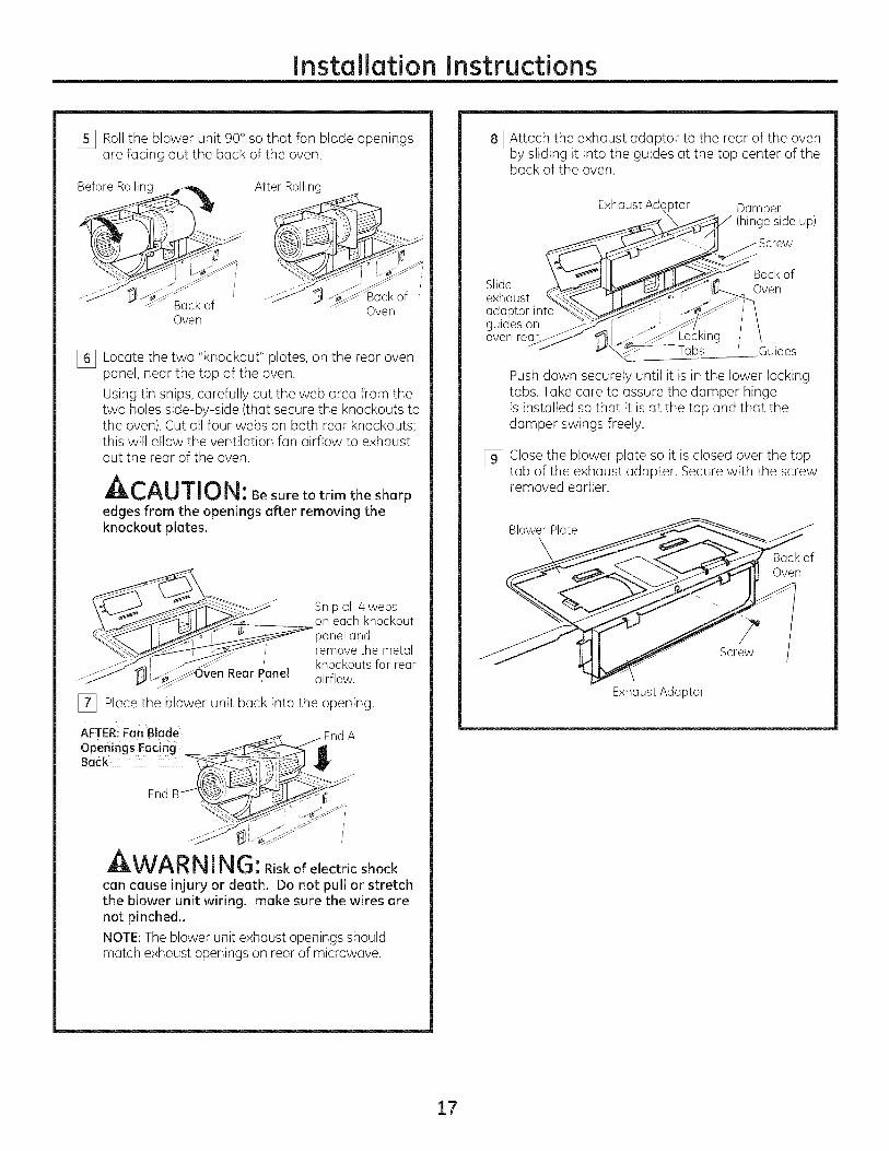
I_ Roll the blower unit 90° so that fan blade openingsare facing out the back of the oven.
BeforeRolling
BackofOven
After Rolling
Back ofOven
% Locate the two "knockout" plates, on the rear ovenpanel, near the top of the oven.
Using tin snips, carefully cut the web area from thetwo holes side-by-side (that secure the knockouts tothe oven). Cut all four webs on both rear knockouts;this will allow the ventilation fan airflow to exhaustout the rear of the oven.
A,,-^_ m-T-,,__,l_._uu ul_: Besuretotrimthesharpedges from the openings after removing theknockout plates.
[_ Place the blower unit back into the opening.
Snip all 4 webson each knockout
panel andremove the metalknockouts for rearairflow.
AFTERiFanBlode .jEnd AOpenings Facing _ IIBack ___J
EndB 0 j _ _y
WA RNING:Riskofelectricshockcan cause injury or death. Do not pull or stretchthe blower unit wiring, make sure the wires arenot pinched..
NOTE:The blower unit exhaust openings shouldmatch exhaust openings on rear of microwave.
I_ Attach the exhaust adaptor to the rear of the ovenby sliding it into the guides at the top center of theback of the oven.
Exhaust Ad%tor Damper(hinge side up)
Slideexhaustadaptor intoguides onoven re%.
Back ofOven
Tabs Guides
Push down securely until it is in the lower lockingtabs. Take care to assure the damper hingeis installed so that it is at the top and that thedamper swings freely.
[_ Close the blower plate so it is closed over the toptab of the exhaust adapter. Secure with the screwremoved earlier.
BlowerPlate
\ Back ofOven
Screw
Exhaust Adaptor
17

Installation Instructions
F_ MOUNT THE OVEN
_,CA UTIO .Toavoidtheriskofpersonalinjury (back injury or other injuries clue to excessiveweight of the microwave) or property damage, youwill need two people to install this microwave.
IMPORTANT: Do not grip or use handle duringinstallation.
_WARN RiskofElectricShock.ING:Can cause injury or death: If installing unitwith metal countertops, cover the edge of the
power supply cord hole with the power supply cordbushing.
IMPORTANT: If filler blocks are not used, case damagemay occur from overtightening screws.
NOTE:When mountingthe microwave, threadpower cord through holein bottom of top cabinet.Keep it tight throughoutSteps 1-3. Do not pinchcord or lift oven by pullingcord.
[_ Lift microwave, tilt itforward, and hook slotsat back bottom edgeonto four lower tabs ofmounting plate.
[_ Rotate front of oven upagainst cabinet bottom.
[_ Insert a self-aligning screw through top-centercabinet hole. Temporarily secure the oven byturning the screw at least two full turns afterthe threads have engaged. (It will be completelytightened later.)
Cabinet Front
Cabinet Bottom Shelf
FillerBlock
_This distanceTEquivalent | can NOT
I to Depth |exceed 2"I of Cabinet |to ensure! _ | proper
_installation
-- Self-Aligning Screw
OvenTop
[_ Attach the oven to the top cabinet.
[_ Insert 2 self-aligning screws(½"-28 x 2 %') through outertop cabinet holes. Turn two fullturns on each screw.
[] Tighten the outer two screws to the top of theoven. (While tightening screws, hold the ovenin place against the wall and the top cabinet.)
II I/
[_ Install grease filters. Seethe Owner's Manualpacked with the oven.
18
Installation Instructions
[ RECIRCULATING {Non-Vented Ductless)
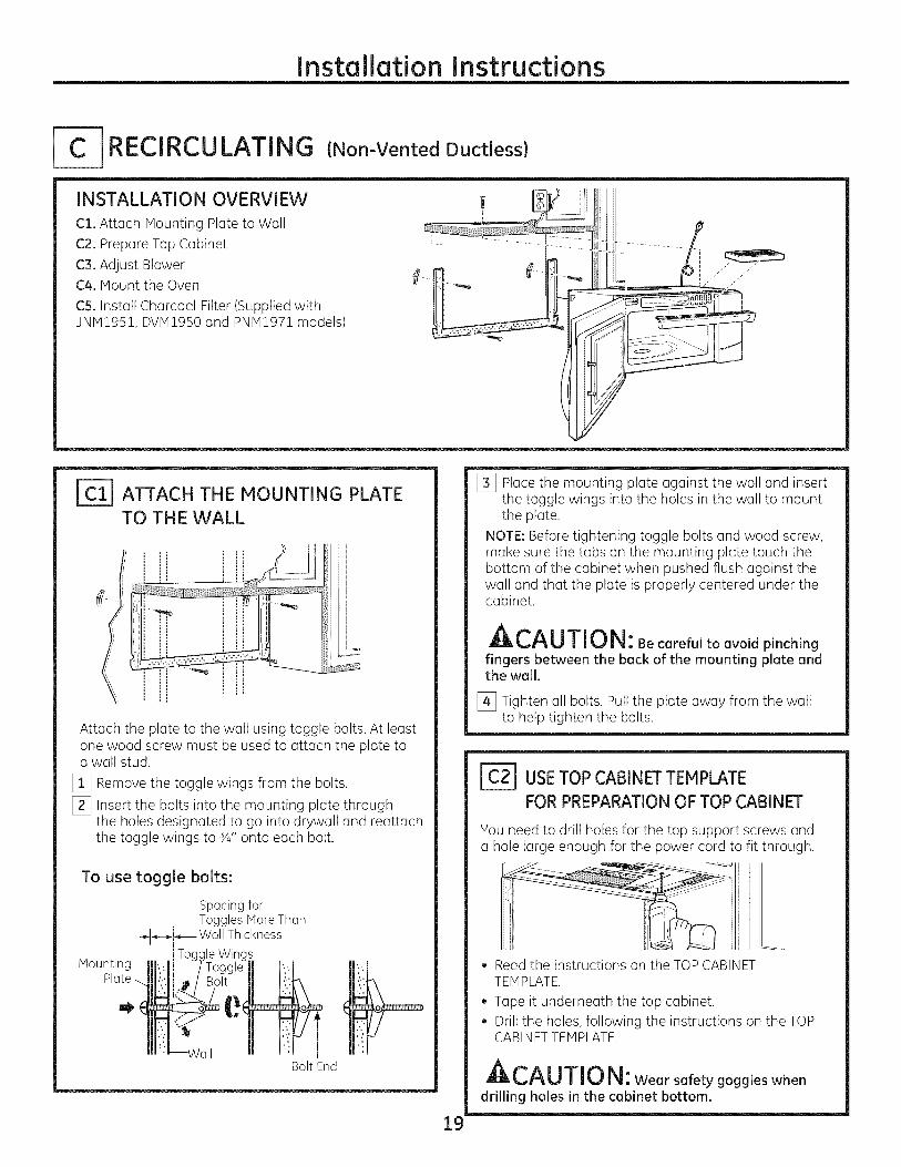
INSTALLATION OVERVIEW
C1. Attach Mounting Plate to Wall
C2. Prepare Top Cabinet
C3. Adjust BlowerC4oMount the Oven
C5. Install Charcoal Filter (Supplied withJNM1951, DVM1950 and PNM1971 models)
I
ATTACH THE MOUNTING PLATE
TO TH E WALL
Attach the plate to the wall using toggle bolts. At leastone wood screw must be used to attach the plate toa wall stud.
[] Remove the toggle wings from the bolts.
[_ Insert the bolts into the mounting plate throughthe holes designated to go into drywall and reattachthe toggle wings to ¾" onto each bolt.
To use toggle bolts:
Spacing forToggles More Than
÷1-_-_,-,----Wa Thicknessl Toc
Mounting
Bolt End
[_ Place the mounting plate against the wall and insertthe toggle wings into the holes in the wall to mountthe plate.
NOTE: Before tightening toggle bolts and wood screw,make sure the tabs on the mounting plate touch thebottom of the cabinet when pushed flush against thewall and that the plate is properly centered under thecabinet.
ACAUTION: Be careful to avoid pinchingfingers between the back of the mounting plate andthe wall.
[_ Tighten all bolts. Pull the plate away from the wallto help tighten the bolts.
lc2l USETOPCABINETTEMPLATEFORPREPARATIONOF TOPCABINET
You need to drill holes for the top support screws anda hole large enough for the power cord to fit through.
19
• Read the instructions on the TOPCABINETTEMPLATE.
• Tape it underneath the top cabinet.Drill the holes, following the instructions on the TOPCABINETTEMPLATE.
A,--^i rrir,_mLL_U||ItJi_i: Wear safety goggles when
drilling holes in the cabinet bottom.
Installation Instructions
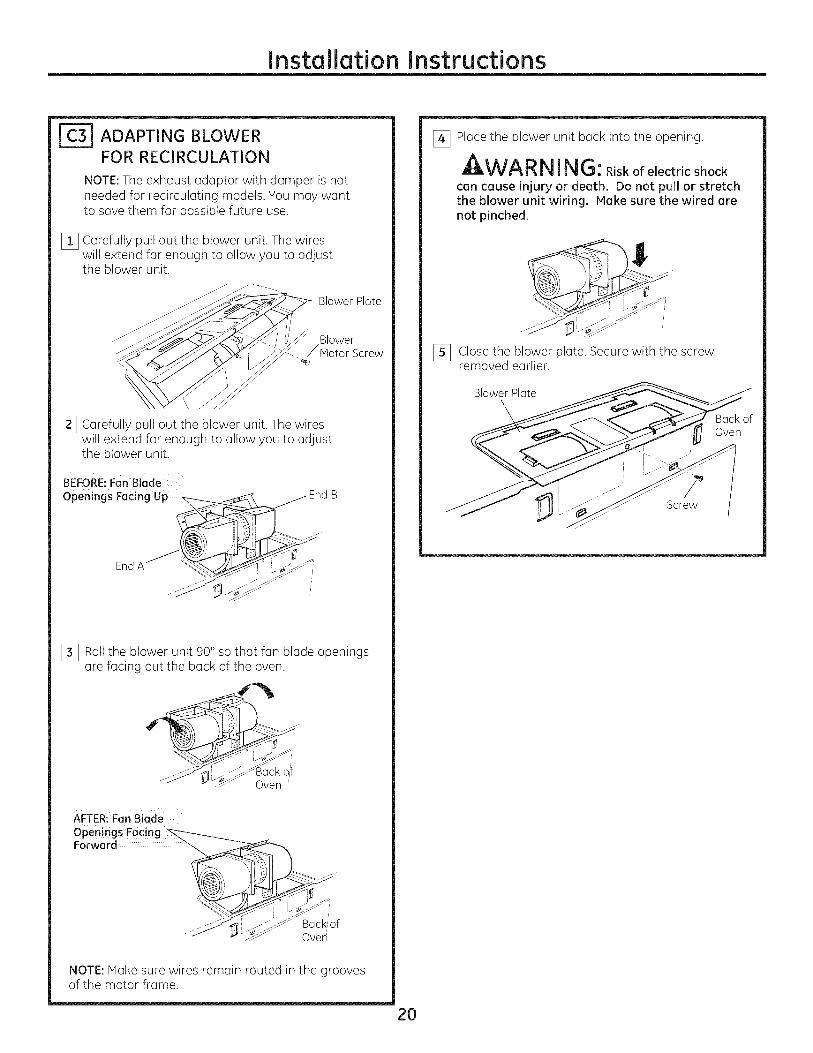
r_ ADAPTING BLOWERFOR RECIRCULATION
NOTE:The exhaust adaptor with damper is notneeded for recirculating models. You may wantto save them for possible future use.
[_ Carefully pull out the blower unit. The wireswill extend far enough to allow you to adjustthe blower unit.
___ BlowerPlate
[_ Carefully pull out the blower unit. The wireswill extend far enough to allow you to adjustthe blower unit.
BEFORE:FanBlade
openings Facing Up ........ EndB
End A "_
[_ Roll the blower unit 90° so that fan blade openingsare facing out the back of the oven.
J-
Oven
AFTER:FanBladeOpeningsFacing _ .....
Forward .......
....._ J _" Oven
NOTE: Make sure wires remain routed in the groovesof the motor frame.
[_ Place the blower unit back into the opening.
_k WA RN !NG: Riskofelectricshockcan cause injury or death. Do not pull or stretchthe blower unit wiring. Hake sure the wired arenot pinched.
[_ Close the blower plate. Secure with the screwremoved earlier.
Blower Plate
Back ofOven
Screw
2O

Installation Instructions
_4-1 MOUNT THE OVEN
_L,_U/|Ui_: TO avoidthe risk ofpersonalinjury (back injury or other injuries due to excessiveweight of the microwave) or property damage, youwill need two people to install this microwave.
IMPORTANT: Do not grip or use handle duringinstallation,
A WARN !NG: RiskofElectricShock.Can cause injury or death: If installing unitwith metal countertops, cover the edge of the
power supply cord hole with the power supply cordbushing.
IMPORTANT:If filler blocks are not used, case damagemay occur from overtightening screws.
NOTE: When mountingthe microwave, threadpower cord through holein bottom of top cabinet.Keep it tight throughoutSteps !-3. Do not pinchcord or lift oven by pullingcord.
[_ Lift microwave, tilt itforward, and hook slotsat buck bottom edgeonto four lower tabs ofmounting plate.
[_ Rotate front of oven upagainst cabinet bottom.
[_ Insert a self-aligning screw through top-centercabinet hole. Temporarily secure the oven byturning the screw at least two full turns afterthe threads have engaged. (It will be completelytightened later.)
Cabinet Front
Cabinet Bottom Shelf
Filler Block
_kThis distanceTEquivaJent |can NOT
J to Depth |exceed 2"[ of Cabinet |toensure
.[ Recess $ proper.._ns_aua_lon
Oven Top
-- Self-Aligning Screw
[_ Insert 2 self-aligning screws(½"-28 x 2%") through outertop cabinet holes. Turn two fullturns on each screw.
[] Tighten the outer two screws to the top of theoven. (While tightening screws, hold the ovenin place against the wall and the top cabinet.)
[_ Install grease filters. See the Owner's Hanualpacked with the oven.
21
Installation Instructions
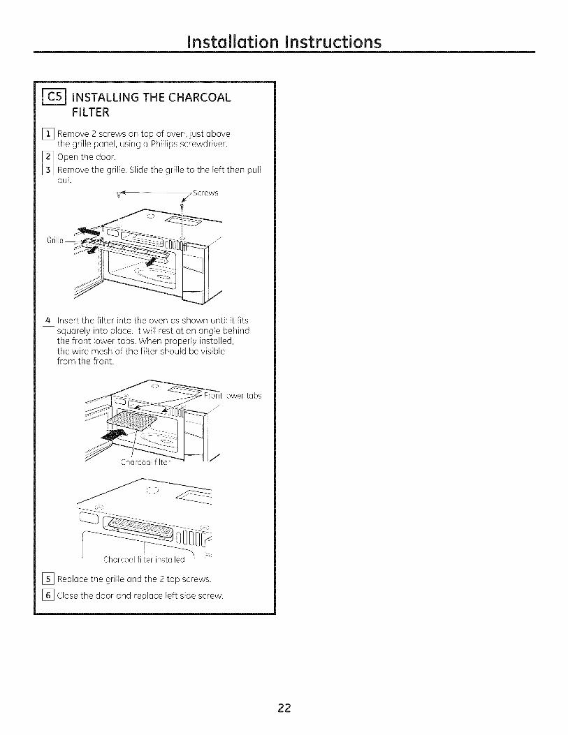
INSTALLING THE CHARCOALFILTER
[_ Remove 2 screws on top of oven, just abovethe grille panel, using a Phillips screwdriver.
[_ Open the door.[_ Remove the grille. Slide the grille to the left then pull
out.
Screws
[_ Insert the filter into the oven us shown until it fitssquarely into place. It will rest at an angle behindthe front lower tabs. When properly installed,the wire mesh of the filter should be visiblefrom the front.
lower tabs/"
J
Charcoal filter
[_ Replace the grille and the 2 top screws.
[_ Close the door and replace left side screw.
22
Installation Instructions
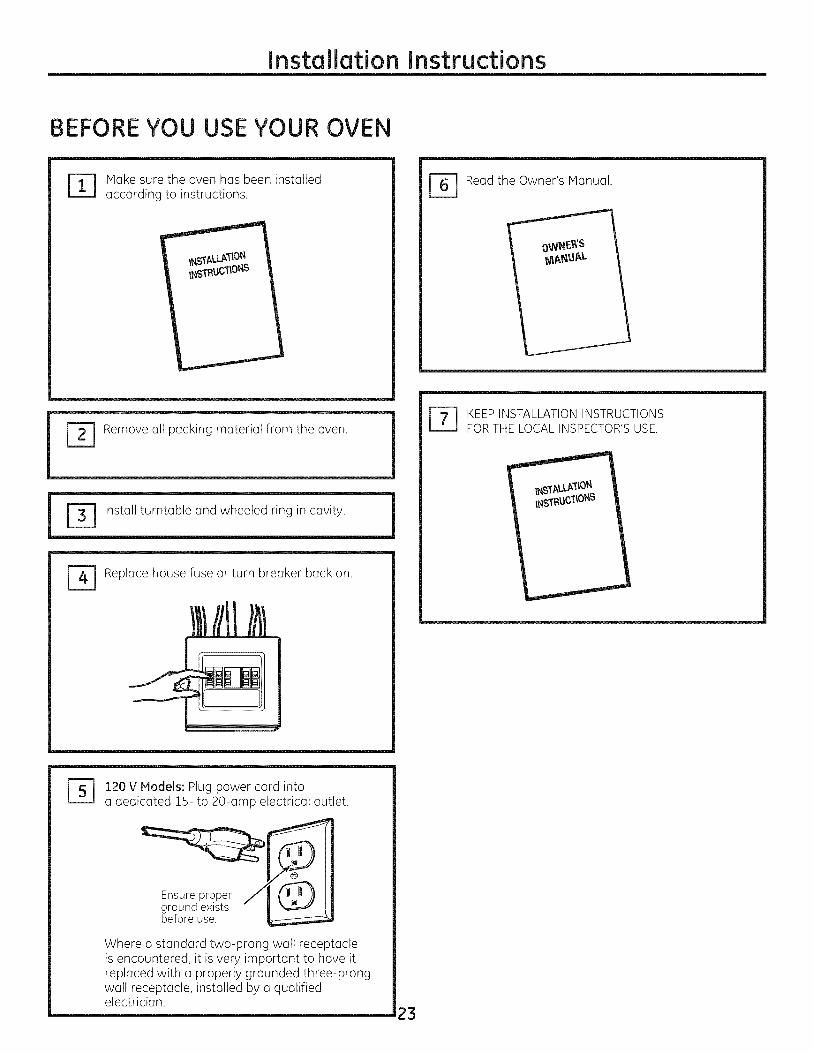
BEFORE YOU USE YOUR OVEN
Make sure the oven has been installedaccording to instructions. [_] Read the Owner's Manual.
Remove all packing material from the oven.
i m
[_] Replace house fuse or turn breaker back on.
r_ EEP INSTALLATION INSTRUCTIONSFOR THE LOCAL INSPECTOR'S USE.
120 V Models: Plug power cord intoa dedicated !5- to 20-amp electrical outlet.
Ensure properground existsbefore use.
Where a standard two-prong wall receptacleis encountered, it is very important to have itreplaced with a properly grounded three-prongwall receptacle, installed by a qualifiedelectrician.
23

24
Printed in Korea
I struccide i stal
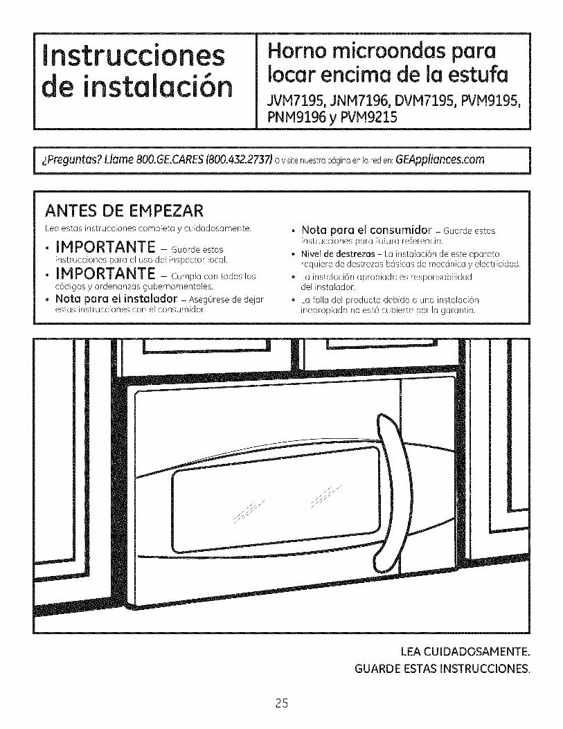
Horno microondas paraiocar encima de ia estufaJVM7195,JNM7196, DVM7195,PVM9195,PNM9196y PVM9215
i
ANTES DE EMPEZARLea estas instrucciones complet° y cuidadosamente.
. IMPORTANTE - Guordeestosinstrucciones paro el uso clel inspector local.
. IMPORTANTE - Cump,ocontodos,osc6digos y ordenanzas gubernamentales.
. Not° par° el instalador - Aseg0resede dejarestas instrucciones con el consumidor.
. Nota par° el consumidor - Guarde estasinstrucciones para futura referencia.
. Nivel de destrezas - LGinstaluci6n de este upurutorequiere de destrezas bc_sicasde mecc_nicay electricidad.
. Lu instaloci6n opropiadu es responsubilidaddel instaludor.
La falla del producto debido a una instalaci6ninapropiada no est6 cubierta por la garant[a.
LEA CUIDADOSAMENTE.
GUARDE ESTAS INSTRUCCIONES.
25
Instrucdonesde instalaci6n
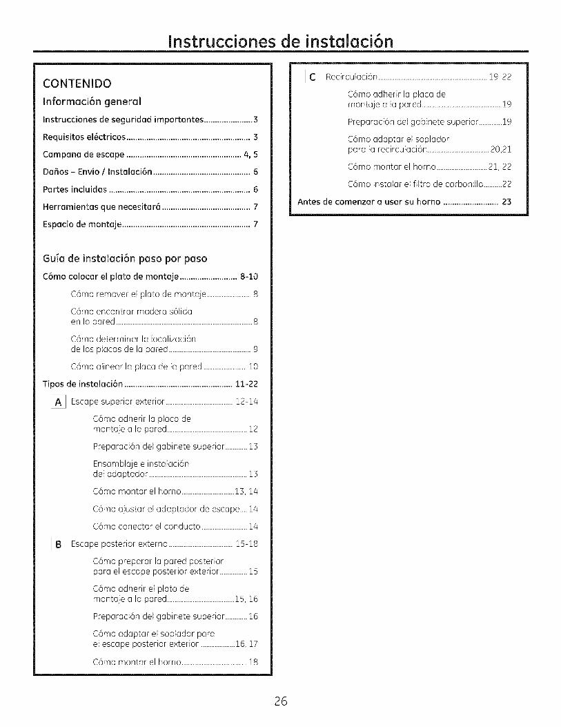
CONTENIDO
Informaci6n general
Instrucciones de seguridad importantes ......................3
Requisitos el_ctricos ........................................................3
Campana de escape ....................................................4, 5
Da_os - Envio / Instalaci6n ............................................6
Partes incluidas ................................................................6
Herramientas que necesitar6 ........................................7
Espacio de montaje ..........................................................7
Guia de instalaci6n paso por paso
C6mo colocar el plato de montaje ..........................8-10
C6mo remover el plato de montaje ........................8
C6mo encontrar madera s61idaen la pared ...........................................................................8
C6mo determinar la Iocalizaci6nde las placas de la pared .............................................9
C6mo alinear la placa de la pared .......................10
Tipos de instalaci6n .................................................11-22
[_ Escape superior .....................................exterior 12-14
C6mo adherir la placa demontaje a la pared ............................................12
Preparaci6n del gabinete superior ............13
Ensamblaje e instalaci6ndel adaptador ......................................................13
C6mo montar el homo .............................13, 14
C6mo ajustar el adaptador de escape....14
C6mo conectar el conducto .........................14
[]_ Escape posterior externo ...................................15-18
C6mo preparar la pared posteriorpara el escape posterior exterior ...............15
C6mo adherir el plato demontaje a la pared .....................................15, 16
Preparaci6n del gabinete superior ............16
C6mo adaptar el soplador parael escape posterior exterior ....................16, 17
C6mo montar el homo ....................................18
[_ Recirculaci6n ............................................................19-22
C6mo adherir la placa demontaje a la pared ............................................19
Preparaci6n del gabinete superior .............19
C6mo adaptar el sopladorpara la recirculaci6n ..................................20,21
C6mo montar el horno ............................21, 22
C6mo instalar el filtro de carbonilla ..........22
Antes de comenzar a usar su homo ......................... 23
26
Instruccionesde instolaci6n
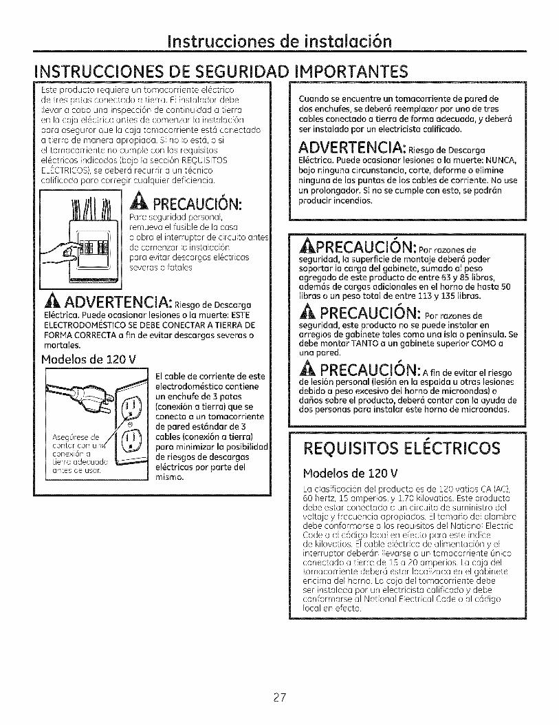
NSTRUCCIONESEste producto requiere un tomacorriente el6ctricode tres patas conectado a tierra. El instalador debeIlevar a cabo una inspecci6n de continuidad a tierraen la caja el6ctrica antes de comenzar la instalaci6npara asegurar que la caja tomacorriente est6 conectadaa tierra de manera apropiada. Si no Io est6, o siel tomacorriente no cumple con los requisitosel6ctricos indicados (bojo la secci6n REQUISITOSELECTRICOS),se deber6 recurrir a un t6cnico
calificado para corregir cualquier deficiencia.
A PRECAUCiON:Para seguridad personal,remueva el fusible de la casao abra el interruptor de circuito antesde comenzar la instalaci6npara evitar descargas el6ctricasseveras o fatales
ADVERTENCIA: Riesgo de Descarga
El_ctrica. Puede ocasionar lesiones o la muerte: ESTEELECTRODOMESTiCO SE DEBE CONECTAR A TiERRA DE
FORMA CORRECTA a fin de evitar descargas severas omortales.
Modelos de 120 V
_ioneXia6dneauada _L,__cont_rconun_
antes de usan
DE SEGURIDAD IMPORTANTES
El cable de corriente de esteelectrodom_stico contiene
un enchufe de 3 patas(conexi6n a tierra) que seconecta a un tomacorriente
de pared est6ndar de 3cables (conexi6n a tierra)
para minimizar la posibilidadde riesgos de descargasel_ctricas par parte delmismo.
Cuando seencuentreun tomacorrientede pareddedosenchufes,sedeber6reemplazarparuno de trescablesconectadoatierrade farinaadecuada,ydeber6serinstaladoparun electricistacalificado.
ADVERTENCIA: Riesgo de Descarga
El_ctrica. Puede ocasionar lesiones o la muerte: NUNCA,
bajo ninguna circunstancia, carte, deforme o elimineninguna de las puntas de los cables de corriente. No useun prolongador. Si no se cumple con esto, se podr6nproducir incendios.
Annrr^l lrl_km_I'I_E_,_'_U L, IV|_: Por razones de
seguridad, la superficie de montaje deber6 podersoportar la carga del gabinete, sumado al pesoagregado de este producto de entre 63 y 85 libras,adem6s de cargas adicionales en el homo de hasta 50libras o un peso total de entre 113 y 135 libras.
J
PRECAUCION: Parrazonesdeseguridad,este producto no se puede instalarenorreglosde gobinetetalescoma una isloo peninsula.Sedebe montar TANTO a un gabinetesuperiorCOMO auno pored.A
PRECAUCION: Afindeevitarelriesgo
de lesi6n personal (lesi6n en la espalda u arras lesionesdebido a peso e×cesivo del homo de microondas) odafios sabre el producto, deber6 contar con la ayuda dedos personas para instalar este homo de microondas.
REQUISlTOS ELI CTRICOS
Modelos de 120 V
La clasificaci6n del producto es de 120 ratios CA (AC),60 hertz, 15 amperios, y 1.70 kilovatios. Este productodebe estar conectado a un circuito de suministro delvoltaje y frecuencia apropiados. El tamaBo del alambredebe conformarse a los requisitos del National ElectricCode o al c6digo local en efecto para este indicede kilovatios. Elcable el@ctrico de alimentaci6n y elinterruptor deber6n Ilevarse a un tomacorriente 6nicoconectado a tierra de 15 a 20 amperios. La caja deltomacorriente deber6 estar Iocalizada en el gabineteencima del homo. La caja del tomacorriente debeset instalada par un electricista calificado y debeconformarse al National Electrical Code o al c6digolocal en efecto.
27
Instruccionesde instalaci6n
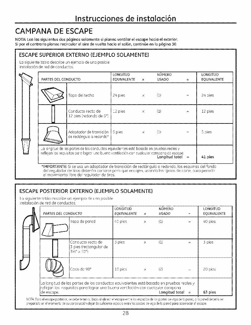
CAMPANA DE ESCAPENOTA: Lea las siguientes dos p6ginas solamente si planea ventilar el escape hacio el exterior.Si por el contrario planea recircular el aire de vuelta hacia el sal6n, contin6e en la p6gina 30.
ESCAPE SUPERIOR EXTERNO (EJEMPLO SOLAMENTE)
La siguiente tabla describe un ejemplo de una posibleinstalaci6n de red de conductos.
PARTES DEL CONDUCTO
LONGITUD NUMERO
EQUIVALENTE x USADO
Tapa del techo
Conducto recto de12 pies (redondo de 6")
24 pies x (!)
12 pies x (!)
LONGITUD
EQUIVALENTE
24 pies
12 pies
R
Adaptador de transici6n 5 pies x (!) : Spiesde rect6nguloa redondo*
LaIongitudde las partes de los conductosequivalentesest6 basadaen pruebas realesyreflejan los requisitospara Iograr una buenaventilaci6n con cualquier campanade escape.
Longitud total = 41 pies
*IMPORTANTE:Sise usa un adaptador de transici6n de rect6ngulo a redondo, las esquinas del fondodel regulador de tiros deber6n cortarse para que encajen, usando las tijeras de corte, para permitirel movimiento libre del regulador de tiros.
ESCAPE POSTERIOR EXTERNO (EJEMPLO SOLAMENTE)
La siguiente tabla describe un ejemplo de una posibleinstalaci6n de red de conductos.
LONGITUD
PARTESDELCONDUCTO
Tapa de pared
Conducto recto de3 pies (rectangular de31A'' x 10")
EQUIVALENTE
40 pies
:3pies
x
x
NOMERO
USADO
(!)
(!)
LONGITUD
EQUIVALENTE
40 pies
:3pies
(_ Codo de 90° !0 pies x (2) = 20 pies
La Iongitud de las partes de los conductos equivalentes est6 basada en pruebas reales yrefiejan los requisitos para Iograr una buena ventilaci6n con cualquier campanade escape. Longitud total = 621pies
NOTA:Paraetescapeposterior,sedebetenercuidadoalalinearelescapeentrelosespaciosdelospostesderigadelapared,o lapareddeberiaserpreparada en etmomentodesuconstrucci6ndejando suficiente espacio entrelospostes de riga delapared paraacomodarelescape.
28
Instruccionesde instalaci6n
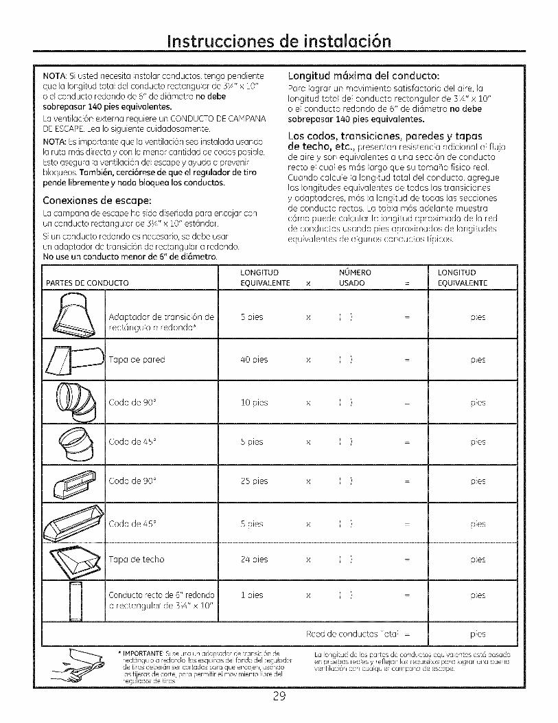
NOTA: Siusted necesita instalar conductos, tenga pendienteque la Iongitud total del conducto rectangular de 3¼" x 10"o el conducto redondo de 6" de di6metro no debesobrepasar 140 pies equivalentes.
La ventilaci6n externa requiere un CONDUCTODECAMPANADEESCAPE.LeaIo siguiente cuidadosamente.
NOTA:Esimportante que laventilaci6n sea instalada usandola ruta mas directa y con la menor cantidad de codos posible.Estoasegura laventilaci6n delescape y ayuda a prevenirbloqueos.Tambi_n, cerci6rese de que el regulador de tiropende libremente y nada bloquea los conductos.
Conexiones de escape:La campana de escape ha sido diseflada para encajar conun conducto rectangular de 3!4" x !0" est6ndar.
Siun conducto redondo es necesario, se debe usarun adaptador de transici6n de rectangular a redondo.No use un conducto menor de 6" de diametro.
Longitud m6xima del conducto:
Para Iograr un movimiento satisfactorio del aire, laIongitud total del conducto rectangular de 3¼" x 10"o el conducto redondo de 6" de di6metro no debesobrepasar 140 pies equivalentes.
Los codos, transiciones, paredes y tapasde techo, etc., presentan resistencia adicional al flujode aire y son equivalentes a una secci6n de conductorecto el cual es m6s largo que su tamaho fisico real.Cuando calcule la Iongitud total del conducto, agreguelas longitudes equivalentes de todas las transicionesy adaptadores, m6s la Iongitud de todas las seccionesde conducto rectas. La tabla m6s adelante muestrac6mo puede calcular la Iongitud aproximada de la redde conductos usando pies aproximados de longitudesequivalentes de algunos conductos t[picos.
LONGITUD NUMERO LONGITUD
PARTES DE CONDUCTO EQUIVALENTE x USADO = EQUIVALENTE
Adaptador de transici6n de 5 pies x ( ) : piesrect6ngulo a redondo*
Tapa de pared 40 pies x ( ) = pies
C]_ Codo de 90° i0 ( )pies × pies
Codo de 45° 5 pies x ( ) = pies
Codo de 90° 25 pies × ( ) = pies
_ Codode45 ° 5 ( )pies x pies
Tapa detecho 24 pies x ( ) = pies
Conducto rectode 6" redondo ! pies x ( ) = pieso rectangular de 3¼" x !0"
Reedde conductos Total = pies
* IMPORTANTE:Si se usa un adaptador de transici6n de La Iongitud de las partes de conductos equivalentes est6 basada
rect6ngulo a redondo, las esquinas del fondo del regulador en pruebas reales y reflejan los requisitos para Iograr una buenade tiros deber6n ser cortadas para que encajen, usando ventilaci6n con cualquier campana de escape.las tijeras de corte, para permitir el movimiento libre delregulador de tiros.
29
Instrucdonesde instalaci6n
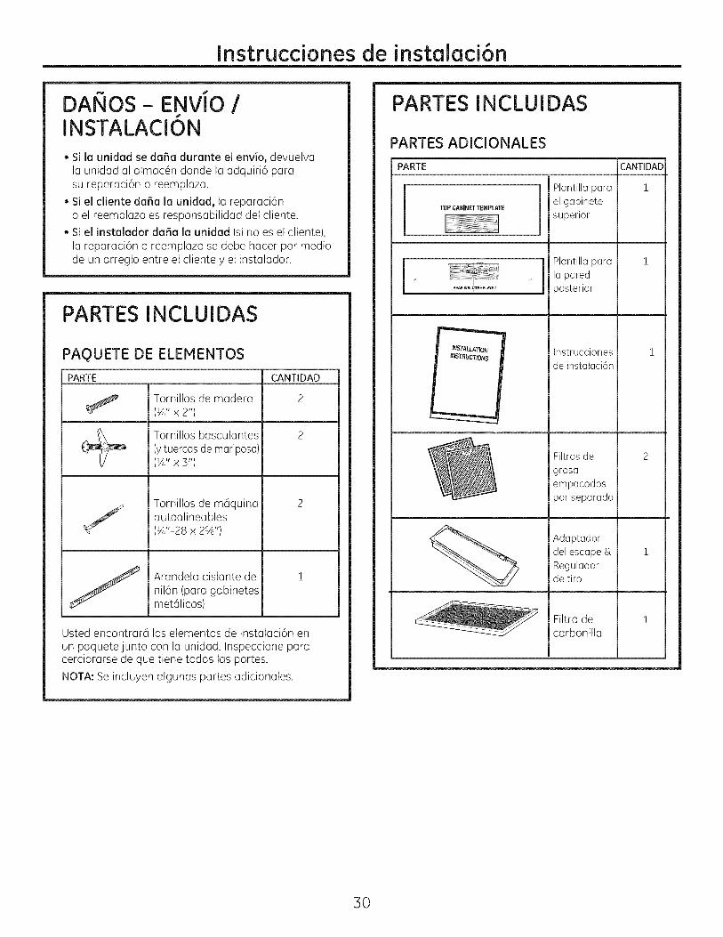
DANOS- ENVJO /J
INSTALACION
• Si la unidad se daSa durante el envio, devuelva
la unidad al almac6n clonde la adquiri6 parasu reparaci6n o reemplazo.
• Si el cliente daSa la unidad, la reparaci6n
o el reemplazo es responsabilidad clel cliente.
• Si el instalador da5a la unidad (si no es el cliente),
la reparaci6n o reemplazo se clebe hacer por meclio
de un arreglo entre el cliente y el instalador.
PARTES INCLUIDAS
PAQUETE DE ELEMENTOS
PARTE CANTIDAD
Tornillos de madera 2(1A"x 2")
Tornillos basculantes 2(y tuercas de mariposa)(1A"x 3")
Tornillos de m6quinaautoalineables(1A"-28x 2%')
Arandela aislante denil6n (para gabinetesmetdlicos)
Usted encontrar6 los elementos de instalaci6n enun paquetejunto con la unidad. Inspeccione paracerciorarse de que tiene todas las partes.
NOTA: Se incluyen algunas partes adicionales.
PARTES INCLUIDAS
PARTES ADICIONALES
PARTE
TOP CABINETTEMPLATE
INBTAU.ATION
INSTRUCTIONS
%
Plantilla para
el gabinetesuperior
Plantilla para
la paredposterior
Instruccionesde instalaci6n
Filtros de
grasaempacados
por separado
Adaptador
del escape &Reguladorde tiro
Filtro decarbonilla
CANTIDAD
1
1
1
2
1
1
3O
Instruccionesde instalaci6n
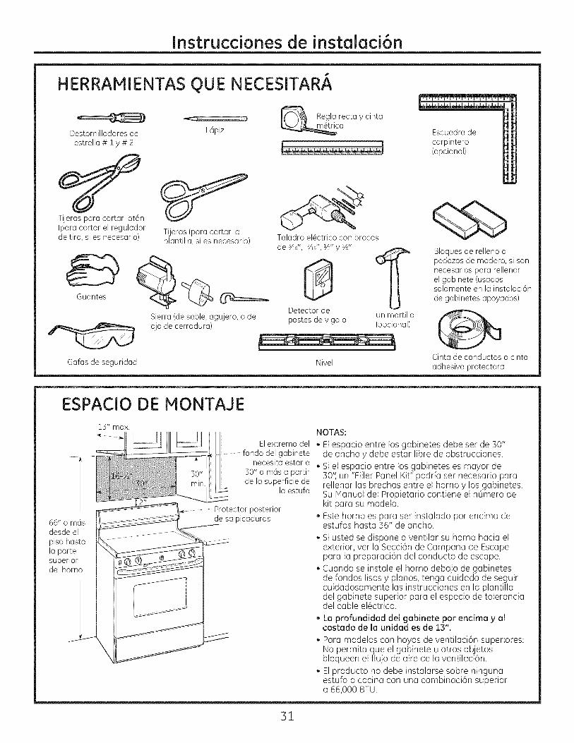
HERRAMIENTAS
Destornilladoresdeestrella# iy # 2
OUE
_Z ......... _J_J_J
L6piz
NECESITARA
_-_ Regl? recta y cinta
_ca Escuadra de
carpintero(opcional)
Tijeras para cortar lat6n(para cortar el reguladorde tiro, si es necesario)
Guantes
Tijeras(paracortar laplantilla,si es necesario)
Sierra(desable,agujero,o deojode cerradura)
Gafas de seguridad
Taladro el@ctrico con brocas
de _/ld', 7/ld',½"y%"
Detectorde un martillopostesde viga o (opcional)
Nivel
Bloques de relleno opedazos de madera, si sonnecesarios para rellenarel gabinete (usadossolamente en la instalaci6nde gabinetes apoyados)
Cinta de conductos o cintaadhesiva protectora
ESPAClO DE MONTAJE
66" o m6sdesde el
piso hastala partesuperiordel homo
13" max.
El extremo deldel gabinete
necesita estar a30" o m6s a partirde la superficie de
la estufa
Protector posteriorde salpicaduras
NOTAS:
. Elespacio entre los gabinetes debe ser de 30"de ancho y debe estar libre de obstrucciones.
. Siel espacio entre los gabinetes es mayor de30'I un "Filler Panel Kit" podr[a set necesario pararellenar las brechas entre el horno y los gabinetes.Su Manual del Propietario contiene el nOmero dekit para su modelo.Este homo es para ser instalado por encima deestufas hasta 36" de ancho.
. Si usted se dispone a ventilar su horno hacia elexterior, ver la Secci6n de Campana de Escapepara la preparaci6n del conducto de escape.
, Cuando se instale el homo debajo de gabinetesde fondos lisos y pianos, tenga cuidado de seguircuidadosamente las instrucciones en la plantilladel gabinete superior para el espacio de toleranciadel cable el6ctrico.
. La profundidad del gabinete por encima y alcostado de la unidad es de 13".
, Para modelos con hoyos de ventilaci6n superiores:No permita que el gabinete u otros objetosbloqueen el flujo de aire de la ventilaci6n.
El producto no debe instalarse sobre ningunaestufa o cocina con una combinaci6n superiora 66,000 BTU.
31
Instruccionesde instalaci6n
C6MO COLOCAR EL PLATO DE MONTAJE
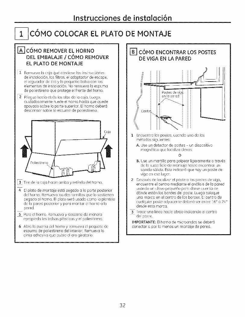
[_] C6MO REMOVER EL HORNO
DEL EMBALAJE / C6MO REMOVER
EL PLATO DE MONTAJE
%
[]
Remueva lu cajo que contiene las instruccionesde instulaci6n, los filtros, el adaptador de escape,el regulador de tiro y la peque_a balsa con loselementos de instalaci6n. No remueva lu espumade poliestireno que protege el frente del horno.
Pliegue hacia atr6s las alas de la caja. Luego,cuidadosumente ruede el homo husta que quedeapoyado sabre la parte superior. Elhomo deber6descansar sabre la espuma de poliestireno.
Poliestireno\
[_ Tire de la caja hacia arriba y retfrela del horno.
% Elpluto de montaje est6 pegado u la parte posteriordel homo. Remueva los dos tornillos que Io sostienenpegado al homo. El plato ser6 usado coma la plantillade la pared posterior y para montar el homo a lapared.
I_ Pare el homo. Remueva y descarte de maneraapropiada las balsas pl6sticas y el poliestireno.
[_ Abru la puerta del homo y remueva el paquete deespuma de poliestireno del interior. Remueva lacinta adhesiva que cubre el aro giratorio.
IBI C6MO ENCONTRAR LOS POSTES
DE VIGA EN LA PARED
Pastesdevig_en la pared i
[_ Encuentre los pastes, usando uno de losm@odos siguientes:A. Use un detector de pastes - un dispositivo
magn@ico que Iocaliza clavos.O
B. Use un martillo para golpear ligeramente a trav6sde la superficie de montaje hasta encontrar unsonido s61ido.Esto indicar6 que hay un paste deriga en ese lugar.
Despu6s de Iocalizar el paste o los pastes de riga,encuentre el centro mediante el an61isisde la paredusando un clara pequeBo para darse cuenta ded6nde est6n los bordes del paste. Luego coloqueuna marca en el centro de los bordes. Elcentro decualquier paste adyacente deber6 ser entre Z6" 6 24"desde esta marca.
%
[_ Trace una linea hacia abajo indicando el centrodel paste.
IMPORTANTE:Elhomo de microondas se deber6conectar a par Io menos un montaje de pared.
32
Instruccionesde instalaci6n
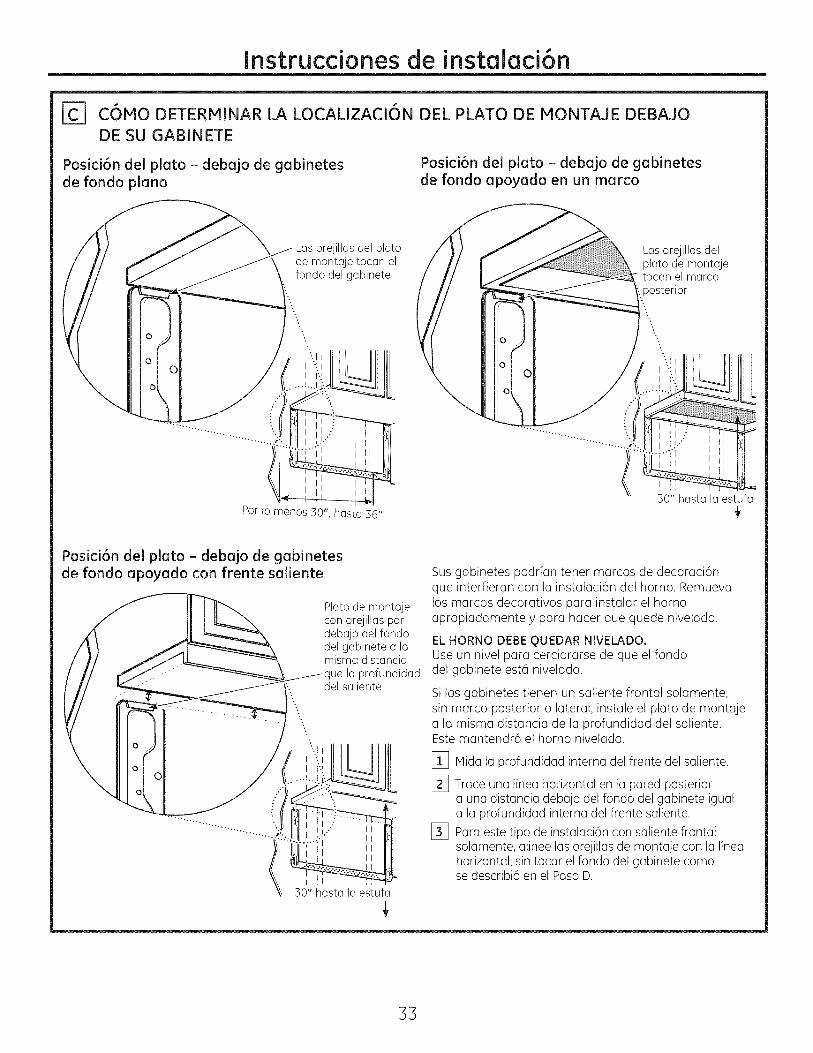
C6MO DETERMINAR LA LOCALIZACION DEL PLATO DE MONTAJE DEBAJODE SU GABINETE
Posici6n del plato - debajo de gabinetesde rondo piano
Posici6n del plato = debajo de gabinetesde rondo apoyado en un marco
o
°oIo
Las orejillas del platode montaje tocan elfondo del gabinete
Lasorejillasdelplato de montajetocan el marcoposterior
Por to menos 30", hasta 36"
30"'hasta la estufa
Posici6n del plato - debajo de gabinetesde fondo apoyado con frente saliente
Plato de montajecon orejillas pordebajo del fondodel gabinete a lamisma distancia
la profundidaddel saliente
30" hasta la estufa
Sus gabinetes podrfan tener marcos de decoraci6nque interfieran con la instalaci6n del horno. Remuevalos marcos decorativos para instalar el homoapropiadamente y para hacer que quede nivelado.
ELHORNO DEBE QUEDAR NIVELADO.Use un nivel para cerciorarse de que el fondodel gabinete est6 nivelado.
Si los gabinetes tienen un saliente frontal solamente,sin marco posterior o lateral, instale el plato de montajea la misma distancia de la profundidad del saliente.Este mantendr6 el homo nivelado.
[] Mida la profundidad interna del frente del saliente.
[_ Trace una linea horizontal en la pared posteriora una distancia debajo del fondo del gabinete iguala la profundidad interna del frente saliente.
[_ Para este tipo de instalaci6n con saliente frontalsolamente, alinee las orejillas de montaje con la lineahorizontal, sin tocar el fondo del gabinete comose describi6 en el Paso D.
33
Instruccionesde instalaci6n
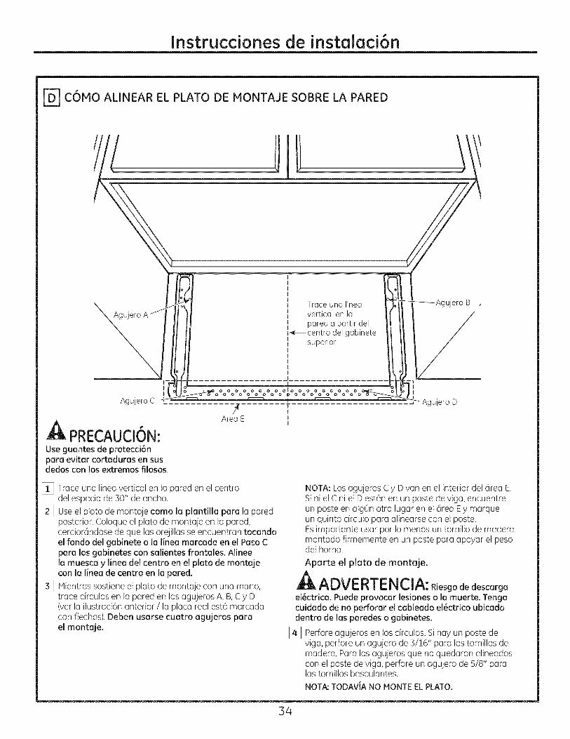
C6MO ALINEAR EL PLATO DE MONTAJE SOBRE LA PARED
Agujero
I
AgujeroC
PRECAUCION:Use guantesde protecci6nparaevitarcortadurasen susdedoscon losextremosfilosos.
Traceuna lineavertical en lapareda partir del
_=--centro del gabinetesuperior
.................. I..................
O0OO0000100000000000o0o00_00000o00
?........TArea E J
I
_Agujero B
/Agujero D
[] Trace una linea vertical en la pared en el centrodel espacio de 30" de ancho.
[_ Useel plato de montaje coma la plantilla para la paredposterior. Coloque el plato de montaje en la pared,cercior6ndose de que las orejillas se encuentran tocandoel fondo del gabinete o la Iinea marcada en el Paso Cpara los gabinetes con salientes frontales. Alineela muesca !#linea del centro en el plato de montajecon la linea de centro en la pared.
[_ Mientras sostiene el plato de montaje con una mano,trace circulos en la pared en los agujeros A, B,C y D(vet la ilustraci6n anterior / la placa real est6 marcadacon flechas). Deben usarse cuatro agujeros parael montaje.
NOTA: Los agujeros C y D van en el interior del 6rea E.Si ni el C ni el D est6n en un paste de viga, encuentreun paste en alg0n otro lugar en el 6rea Ey marqueun quinto c[rculo para alinearse con el paste.Esimportante usar par Io menus un tornillo de maderamontado firmemente en un paste para apoyar el pesodel horno.
Apurte el pluto de montuje.
ADVERTENCIA: RJesgode descarga
el_ctrica. Puede provocar lesiones o la muerte. Tengacuidado de no pefforar el cableado el_ctrico ubicadodentro de los parades o gabinetes.
[_ Perfore agujeros en los c[rculos. Sihay un paste deriga, peffore un agujero de 3/16" para los tornillos demadera. Para los agujeros que no quedaron alineadoscon el paste de riga, perfore un agujero de 5/8" paralos tornillos basculantes.
NOTA:TODAVJANO MONTEELPLATO,
34
Instruccionesde instalaci6n
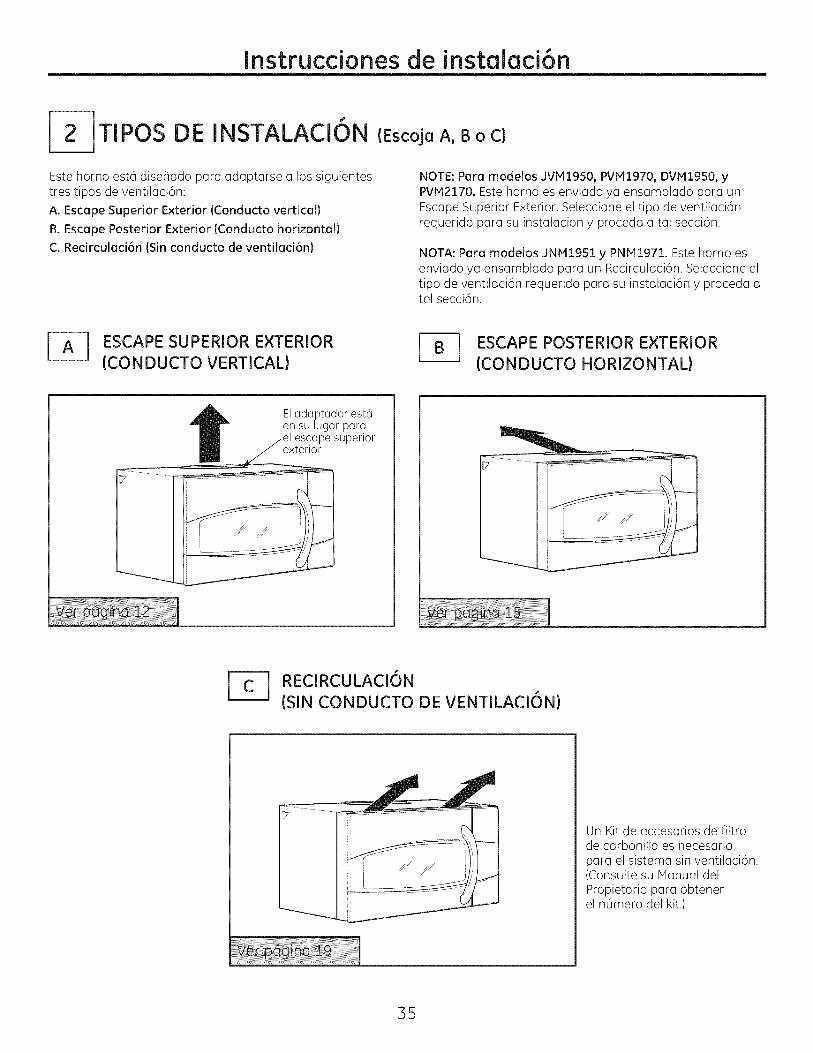
2-JTIPOS DE INSTALACION
Este homo est6 disehado para adaptarse a los siguientestres tipos de ventilaci6n:
A. Escape Superior Exterior (Conducto vertical)
B. Escape Posterior Exterior (Conducto horizontal)C. Recirculaci6n (Sin conducto de ventilaci6n)
(Escoja A, B o C)
NOTE:Para modelos JVMI950, PVMI970, DVM1950, yPVM2170. Este homo es enviado ya ensamblado para unEscape Superior Exterior. Seleccione el tipo de ventilaci6nrequerido para su instalaci6n y proceda a tal secci6n.
NOTA: Para modelos JNMI951 y PNMI971. Este homo esenviado ya ensamblado para un Recirculaci6n. Seleccione eltipo de ventilaci6n requerido para su instalaci6n y proceda atal secci6n.
ESCAPE SUPERIOR EXTERIOR(CONDUCTO VERTICAL)
J_ SCAPE POSTERIOR EXTERIOR(CONDUCTO HORIZONTAL)
Eladaptador est6ensu lugar para
escapesuperiorexterior
_---_ RECIRCULACI6N(SIN CONDUCTO DE VENTILACI6N)
Un Kit de accesorios de filtrode carbonilla es necesariopara el sistema sin ventilaci6n.(Consulte su Manual delPropietario para obtenerel nOmero del kit.)
35
Instrucdonesde instalaci6n
ESCAPESUPERIOR EXTERIOR(Conducto vertical)
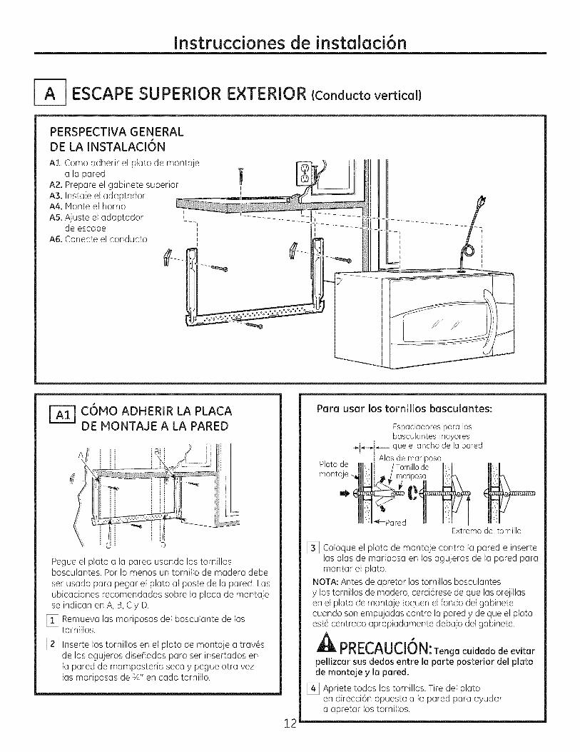
PERSPECTIVA GENERALDE LA INSTALACION
AI. Como adherir el plato de montajea la pared
A2. Prepare el gabinete superiorA3. Instale el adaptadorA4. Monte el homoA5. Ajuste el adaptador
de escapeA6. Conecte el conducto
COMO ADHERIR LA PLACADE MONTAJE A LA PARED
Af _ ]!
'Pegue el plato a la pared usando los tornillosbasculantes. Por Io menos un tornillo de madera debeset usado para pegar el plato al poste de la pared. Lasubicaciones recomendadas sobre la placa de montajese indican en A, B, C y D.
[] Remueva las mariposas del basculante de lostornillos.
[_ Inserte los tornillos en el plato de montaje a trav6sde los agujeros diseflados para ser insertados enla pared de mamposteria seca y pegue otra vezlas mariposas de sA" en cada tornillo.
12
Para usar los tornillos basculantes:
Plato demonta
Espaciadorespara losbasculantesmayores
÷_.-_j_--J que elancho de laparedi Alas de mariposa
"_-ParedExtremodel tornillo
[_ Coloque el plato de montaje contra la pared e insertelas alas de mariposa en los agujeros de la pared paramontar el plato.
NOTA:Antes de apretar los tornillos basculantesy los tornillos de madera, cerci6rese de que las orejillasen el plato de montaje toquen el fondo del gabinetecuando son empujadas contra la pared y de que el platoest6 centrado apropiadamente debajo del gabinete.
A "PRECAUCION:Tenga cuidadode evitar
pellizcarsusdedos entrelaparteposteriordelplatode montajey lapared.
[_ Apriete todos los tornillos. Tire del platoen direcci6n opuesta a la pared para ayudara apretar los tornillos.
Instruccionesde instalaci6n
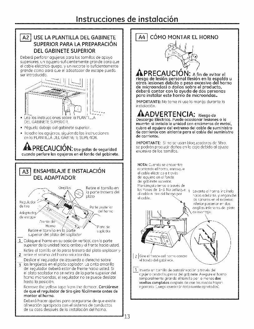
_USE LA PLANTILLA DEL GABINETESUPERIOR PARA LA PREPARACI6N
DEL GABINETE SUPERIOR
Deber6 perforer egujeros pera los tornillos de epoyosuperiores, un egujero suficientemente grende pure queel cable el6ctrico quepe, yun recorte Io suficientementegrende como peru que el edeptedor de escape puedeset introducido.
* Lea les instrucciones sobre lu PLANTILLADELGABINETESUPERIOR.
, P6guelo debejo del gubinete superior., Teludre los ugujeros, siguiendo lus instrucciones
en le PLANTILLADELGABINETESUPERIOR.
PRECAUCION:Use gafas de seguridadcuando perfore los agujeros en el fondo del gabinete.
_-_ ENSAMBLAJE E INSTALACIONDEL ADAPTADOR
Orejillas
Reguladorde tiro -%
Adaptadcde escape
Frente dHomo
Retire el tornillo en la partesuperior del plato del soplador
Retire el tornillo enla parte trasera delplato
Parte posteriordel homo
del
soplador
[_ Coloque el horno en su posici6n vertical, con la partesuperior de la unidad hacia arriba y el frente hacia usted.Retire el tornillo en la parte trasera del plato soplador y
[_ retire el mismo del homo microondas.Deslice el regulador de izquierda a derecha sobre
[_ las leng0etas en el plato soplador. La cinta amarilladel regulador deber6 estar de frente hacia usted. Siel plato soplador no se retira de la parte superior delhomo microondas, el regulador no se puede deslizarhasta la posici6n.Remove the yellow tape from the damper. Cerci6resede que el regulador de tiro gira f6cilmente antes demontar el homo.
Deber6 hecer ajustes pare asegurerse de que existeelineeci6n epropiade con el sisteme de conductosde su case despu6s de le insteleci6n del horno.
13
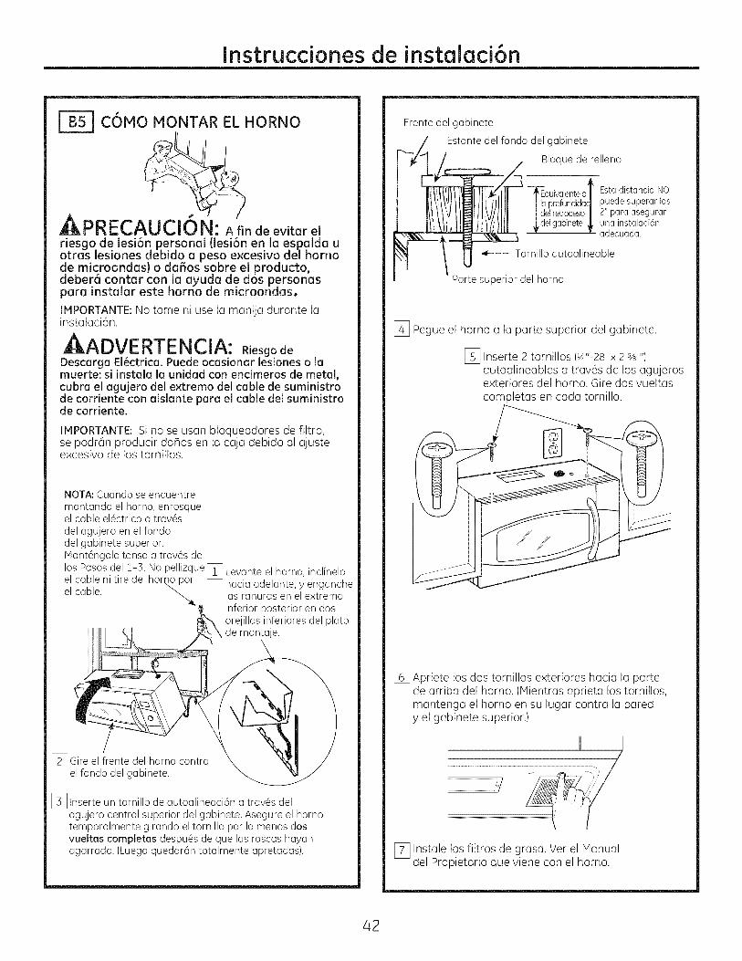
COMO MONTAR EL HORNO
: A fin de evitar elriesgo de lesi6n personal (lesi6n en la espalda uotras lesiones debido a peso e×cesivo del homode microondas) o daBos sobre el producto,deber8 confer con la ayuda de dos personaspara instalar este horno de microondas.
IMPORTANTE:No tome ni use la manije durante lainstalaci6n.
ADVERTENCIA: RiesgodeDescarga El_ctrica. Puede ocasionar lesiones o lamuerte: si instala la unidad con encimeros de metal,cubra el agujero del e×tremo del cable de suministrode corriente con aislante pare el cable del suministrode corriente.
IPIPORTANTE: Si no se usan bloqueadores de filtro,se podr6n producir dahos en la caja debido al ajusteexcesivo de los tornillos.
NOTA: Cuando se encuentre
montando el homo, enrosqueel cable el@ctricoa trav@sdel agujero en el fondodel gabinete superior.Mant#ngalo tenso a tray,s delos Pasos del i-3. ' _1No pelhzque Levante el homo, inclineloel cable ni tire del homo_,por L_ hacia adelante, y enganche
el cable. _ las ranuras en el extremoinferior posterior en dosorejillas inferiores del platode montaje.
1_ Gire el frente del homo contrael fondo del gabinete.
[_ Inserte un tornillo de autoalineaci6n a trav@s delagujero central superior del gabinete. Asegure el homotemporalmente girando el tornillo por Io menos dosvueltas completas despu@sde que las roscas hayanagarrado. (Luego quedar6n totalmente apretadas).

Instruccionesde instalaci6n
COHO MONTAR EL HORNO(continuad6n}
[_ Pegue el homo o Io porte superior del gubinete.
[_ Inserte 2 tornillos (VJ'-28 x 2 sA")outoalineables a troves de los agujerosexteriores superiores del homo. Giredos vueltos completos en coda tornillo.
Frente del gubinete
Estunte del fondo del gubinete
Bloque de relleno
quivalentea t
profundidadJelretroceso|
Esta distancia NOpuede superar las2" para aseguraruna instalaci6nadecuada.
Tornillo autoalineable
Porte superior del homo
[] Apriete los dos tornillos exteriores hacia la partede arriba del horno. (Mientras aprieta los tornillos,mantenga el homo en su lugar contra la paredy el gabinete superior.)
[_ Instale los filtros de grasa. Ver el Manual del Propietario queviene con el horno.
J-ATJC6MO AJUSTAR EL ADAPTADORDE ESCAPE
Abra el gabinete superior y ajuste el adaptadorde escape para conectarlo al conducto de la casa.
Regulador de tiro
Porte posteriordel homo
C6MO CONECTAR EL CONDUCTO
Conducto de la casa
[] Extienda el conducto de la casa hacia abajo paraconectarlo con el adaptador de escape.
[_ Selle lasjuntas del conducto de escape usandoanta adhesiva de conductos.
14

Instruccionesde instalaci6n
ESCAPE POSTERIOR
PERSPECTIVA GENERALDE LA INSTALACI6N
BIo Prepare la pared posteriorB2. Pegue el plato de montaje
a la paredB3. Prepare el gabinete superiorB4, Ajuste el sopladorB5.Monte el homo
E×TERNO
II
(Cond ucto horizonta I)
II
IL
C6HO PREPARAR LA PAREDPOSTERIOR PARA EL ESCAPE
POSTERIOR EXTERIORNecesita cortar una abertura en la pared posterior parael escape exterior.
, Lea las instrucciones en la PLANTILLA PARALA PARED POSTERIOR.
,, P6guelacon cinta adhesiva a la pared posterior,aline6ndola con los agujeros previamente perforadospara los agujeros A y Ben el plato de la pared.
, Corte la apertura, siguiendo las instruccionesde la PLANTILLA PARA LA PARED POSTERIOR.
C6HO ADHERIR EL PLATODE IONTAJE A LA PARED
i ...........-_ iii/ i i
Pegueel plato a la pared usando los tornillos basculantes.Pot Io menos un tornillo de madera debe ser usado parapegar el plato al poste de riga de la pared.
[] Remueva las mariposas de los tornillos.
[_ Inserte los tornillos en el plato de montaje a tray,sde los agujeros dise_ados para colocarse contrala pared de mamposteHa seca y pegue otra vezlas mariposas de sA" a cada tornillo.
39
Instruccionesde instalaci6n
Para usar los tornillos basculantes:
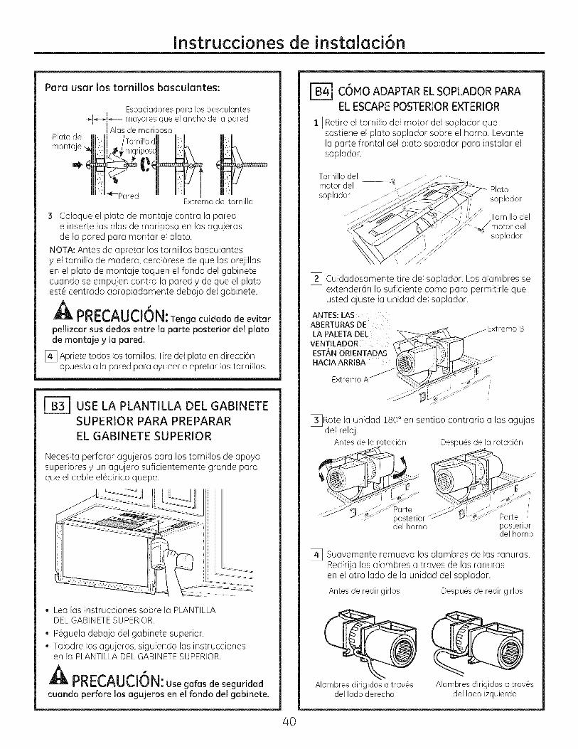
[_ Coloque el plato de montaje contra la parede inserte las alas de mariposa en los agujerosde la pared para montar el plato.
NOTA: Antes de apretar los tornillos basculantesy el tornillo de madera, cerci6rese de que las orejillasen el plato de montaje toquen el fondo del gabinetecuando se empujen contra la pared y de que el platoest6 centrado apropiadamente debajo del gabinete.
A "PRECAUCION:Tenga cuidadode evitarpellizcar sus dedos entre la parte posterior del platode montaje y la pared.
[_ Apriete todos los tornillos. Tire del plato en direcci6nopuesta a la pared para ayudar a apretar los tornillos.
USE LA PLANTILLA DEL GABINETE
SUPERIOR PARA PREPARAR
EL GABINETE SUPERIOR
Necesita perforar agujeros para los tornillos de apoyosuperiores y un agujero suficientemente grande paraque el cable el6ctrico quepa.
, Lea las instrucciones sobre la PLANTILLADELGABINETESUPERIOR.
, P6guela debajo del gabinete superior.
Taladre los agujeros, siguiendo las instruccionesen la PLANTILLADELGABINETESUPERIOR.
A "PRECAUCION:Use galasde seguridadcuando perforelosagujerosen elrondodelgabinete.
FB4] C6MO ADAPTAR ELSOPLADOR PARAELESCAPEPOSTERIOR EXTERIOR
[_ Retire el tornillo del motor del soplador quesostiene el plato soplador sobre el homo. Levantela parte frontal del plato soplador para instalar elsoplador.
Tornillodel
motor del ____- Plat,osoplador _ _,s_ J--c-"_J\ .,_/ sop_aaor
_< ....
___-__./_ Tornillodel
_"___" ._,_'_-_ ,_/'motor delsoplador
[_ Cuidadosamente tire del soplador. Los alambres seextender@n Io suficiente como para permitirle queusted ajuste la unidad del soplador.
ANTES: LASABERTURAS DE
LA PALETA DEL _'__ _Extremo B
VENTJLADOR __'_T'qESTANORIENTADAS _::_ I '_;I _ ....HACIA ARRIBA ((_,: J_ h_'_
ExtremoA
j-
.>J
[_Rote la unidad !80 ° en sentido contrario a las agujasdel reloj.
Antesde la rotaci6n Despu6sde la rotaci6n
_arteposteriordel homo
Parteposteriordel homo
[_ Suavemente remueva los alambres de las ranuras.RedirUalos alambres a tray,s de las ranurasen el otro lado de la unidad del soplador.
Antes de redirigirlos Despu6s de redirigirlos
Alambres dirigidos a trav6s Alambres dirigidos a trav6sdel lado derecho del lado izquierdo
40
Instruccionesde instalaci6n
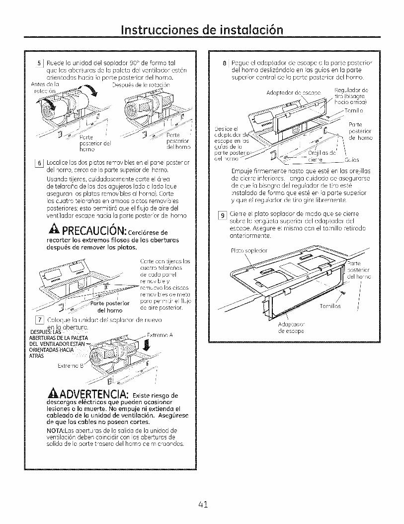
I_ Ruede la unidad del soplador 900 de forma talque las aberturas de la paleta del ventilador est6norientadas hacia la parte posterior del homo.
Antesde la Despu6sde la rotaci6n
Parteposteriordelhorno
Darteposteriordel homo
% Localice los dos platos removibles en el panel posteriordel homo, cerca de la parte superior del homo.
Usando tijeras, cuidadosamente corte el 6reade telaraha de los dos agujeros lado a lado (queaseguran los platos removibles al homo). Cortelas cuatro telara_as en ambos platos removiblesposteriores; esto permitir6 que el flujo de aire delventilador escape hacia la parte posterior del homo.
PRECAUCION:Cerci6resederecortar los extremos filosos de las aberturasdespu6s de remover los platos.
__ Cortecon tijeras las
cuatro telara_as_ de carla panel
removibleyremuevalosdiscos
_ removibles de metal
del horno de aire posterior.
[_ Coloque la unidad del soplador de nuevoen la abertura.
DESPUES:LASABERTURASDELAPALETA
J
Extremo
_l-_UV_.K|_,.mL, Jl-_: E×iste riesgo dedescargas el6ctricas que pueden ocasionarlesiones o la muerte. No empuje ni e×tienda elcableado de la unidad de ventilaci6n. Aseg6resede que los cables no posean cortes.NOTA:Lasaberturas de la salida de la unidad deventilaci6n deben coincidir con las aberturas desalida de la parte trasera del homo de microondas.
I_ Pegue el adaptador de escape a la parte posteriordel horno desliz6ndolo en las gufas en la partesuperior central de la parte posterior del horno.
Adaptador de escape Regulador de
hacia arriba)
ParteDeslice el posterioradaptador del homoescape en lasguias de laparte poste 1_ .-_- illas de /
del homo M_.- _ cierre Guias
Empuje firmemente hasta que est_ en las orejillasde cierre inferiores. Tanga cuidado de asegurarsede que la bisagra del regulador de tiro est6instalada de forma que est6 en la parte superiory que el regulador de tiro gire libremente.
% Cierre el plato soplador de modo que se cierresobre la leng(Jeta superior del adaptador delescape. Asegure el mismo con el tornillo retiradoanteriormente.
Platosoplador
\posteriordel homo
Tornillos
Adaptadorde escape
41
Instruccionesde instalaci6n
COHO MONTAR EL HORNO
rRC . U IUI :AriodeevitoreJriesgo de lesi6n personal (lesi6n en la espalda uotras lesiones debido a peso excesivo del homode microondas) o daffos sobre el producto,deber6 contar con la ayuda de dos personaspara instalar este homo de microondas.
IMPORTANTE: No tome ni use la manUa durante lainstalaci6n.
,ADVERTENCIA: Riesgo deDescarga El_ctrica.Puede ocasionar lesioneso lamuerte: siJnstalalaunidad con encimeros de metal,cubra elagujero del extremo delcable de suministrode corrientecon aislantepara elcable delsuministrode corriente.
IHPORTANTE: Si no se usan bloqueadores de filtro,se podr6n producir dahos en la caja debido al ajusteexcesivo de los tornillos.
NOTA: Cuando se encuentre
montando el homo, enrosqueel cable el#ctrico a tray,s
del agujero en el fondodel gabinete superior.Mant#ngalo tenso a tray,s de
los Pasos del 1-3. No pellizque _l Levante el homo, inclinelo
el cable ni tire del homo por LC_ hacia adelante, y engancheel cable, las ranuras en el extremo
inferior posterior en dos
orejillas inferiores del platode montaje.
[]Gire el frente del homo contrael fondo del gabinete.
[_Inserte un tornillo de autoalineaci6n a trav@sdelagujero central superior del gabinete. Asegure el homotemporalmente girando el tornillo por Io menos dosvueltas completas despu@sde que las roscas hayanagarrado. (Luego quedar6n totalmente apretadas).
Frente del gabinete
Estante del fondo del gabinete
Bloque de relleno
"TEquivalenteaI laprdundidacI del retsoceso
_del gabinete
Esta distancia NO
puede superar las2" para aseguraruna instalaci6nadecuada.
Tornillo autoalineable
Parte superior del homo
[_ Pegue el horno a la parte superior del gabinete.
[] Inserte 2 tornillos (Y4"-28x 2 % ")autoalineables a tray,s de los agujerosexteriores del horno. Gire dos vueltascompletas en cada tornillo.
[] Apriete los dos tornillos exteriores hacia la partede arriba del homo. (ivlientras aprieta los tornillos,mantenga el homo en su lugar contra la paredy el gabinete superior.)
ii j. -_ /
.....................................................,,,
I_ Instale los filtros de grasa. Vet el Manualdel Propietario que viene con el homo.
42
Instrucdonesde instalaci6n
RECIRCULACION {sinconducto de ventilaci6n)
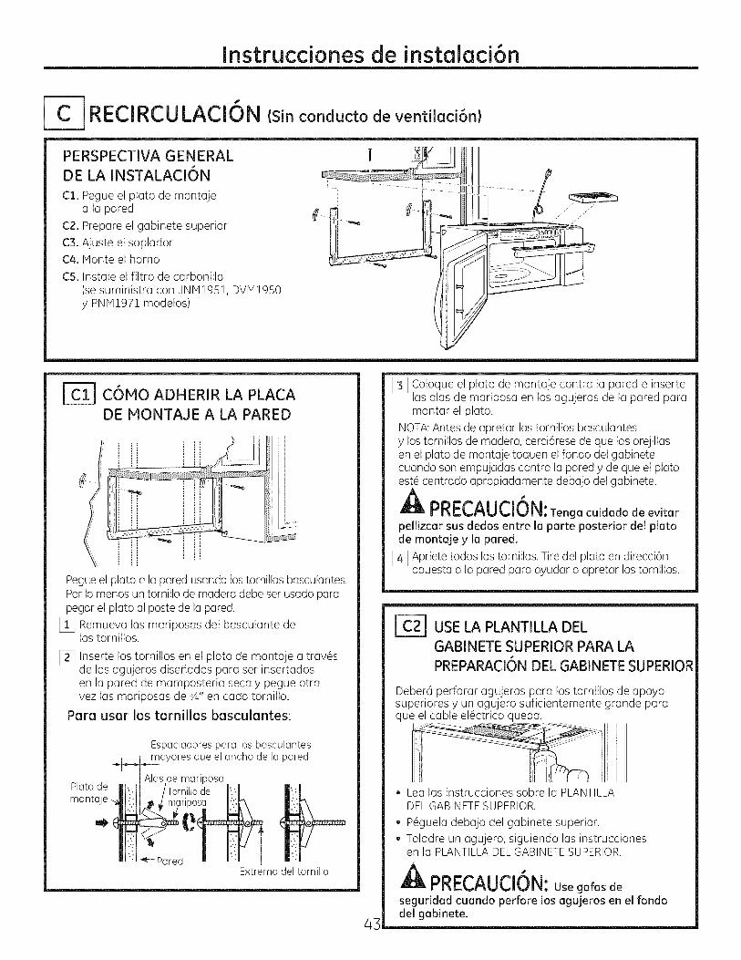
PERSPECTIVA GENERAL W 11DE LA INSTALACI6N
C1. Pegue el plato de montaje ii -a la pared __._. 6--
C2. Prepare el gabinete superior
C3. A]uste el sopladorC4. Monte el horno ..............:__r-
C5. Instale el filtro de carbonilla(se suministro con JNM1951, DVM1950y PNM1971 modelos)
C6MO ADHERIR LA PLACA
DE MONTAGE A LA PARED
Pegueel plato a la pared usando los tornillos basculantes.Pot Io menos un tornillo de madera debe ser usado parapegar el plato al poste de la pared.
[] Remueva las mariposas del basculante delos tornillos.
[_ Inserte los tornillos en el plato de montaje a trav6sde los agujeros disehados para ser insertadosen la pared de mamposteria seca y pegue otravez las mariposas de s,_,,en cada tornillo.
Para usar los tornillos basculantes:
Plato demonta
Espaciadorespara los basculantes; mayoresque elancho de la pared
i Alasde mariposa
, po¢;;k
_---Pared n _._Extremodel tornillo
[_ Coloque el plato de montaje contra la pared e insertelas alas de mariposa en los agujeros de la pared paramontar el plato.
NOTA:Antes de apretar los tornillos basculantesy los tornillos de madera, cerci6rese de que las orejillasen el plato de montaje toquen el rondo del gabinetecuando son empujadas contra la pared y de que el platoest6 centrado apropiadamente debajo del gabinete.
A °PRECAUCiON:Tenga cuidadode evitarpellizcar sus dedos entre la parte posterior del platode montaje y la pared.
[_ Apriete todos los tornillos. Tire del plato en direcci6nopuesta a la pared para ayudar a apretar los tornillos.
4_
USELA PLANTILLA DELGABINETE SUPERIOR PARA LA
PREPARACI6NDEL GABINETESUPERIOR
Deber6 perforar agujeros para los tornillos de apoyosuperiores y un agujero suficientemente grande paraque el cable el6ctrico quepa.
. Lea las instrucciones sobre la PLANTILLADELGABINETESUPERIOR.
, P6guela debajo del gabinete superior., Taladre un agujero, siguiendo las instrucciones
en la PLANTILLADELGABINETESUPERIOR.
PRECAUCION:Use gafasde
seguridadcuando perforelosagujerosen elfondodelgabinete.
Instruccionesde instalaci6n
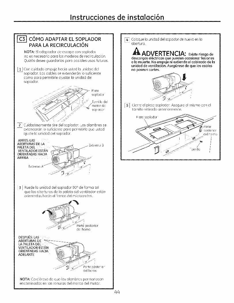
C6MO ADAPTAR EL SOPLADORPARA LA RECIRCULACION
NOTA: Eladaptador de escape con sopladorno es necesario para los modelos de recirculaci6n.Quizds desee guardarlos para posibles usos futuros.
[] Con cuidado empuje hacia usted la unidad delsoplador. Los cables se extender6n Io suficientecomo para permitirle ajustar la unidad delsoplador.
_..-_._'_%-'>.J.J_,i li_ Tornillo delY""S_"..__ y'Y .._</</motor del
_xX%>" \ ff__v_.__ _ sop lador
[_ Cuidadosamente tire del soplador. Los alambres seextender6n Io suficiente para permitirle que ustedajuste la unidad del soplador.
ANTES: LASABERTURAS DE LAPALETA DELVENTILADOR EST#,N
ORIENTADAS HACIAARRIBA
Extremo B
Extremo
[_ Ruede la unidad del soplador 900 de forma talque las aberturas de la paleta del ventilador est6norientadas hacia el frente del microondas.
__Par!e posteriorzj wJ-_- del homo
DESPUES:LASABERTURASDE __ka PALETA DEE __VENTILADOR ESTAN __',_ lORIENTADAS HACIA \lYre\, _II_Ai _ .......
.......... , _f_JPGrte p6sterior.....NOTA: Cerci6rese de que los alambres permanecenencaminados en las ranuras del marco del motor.
[_ Coloque la unidad del soplador de nuevo en laabertura.
AADVERTENCIA: E×iste riesgo de
descargas ei6ctricas que pueden ocasionar lesioneso la muerte. No empuje ni extienda el cableado de launidad de ventilaci6n. Aseg6rese de que los cablesno posean cortes.
[_ Cierre el plato soplador. Asegure el mismo con eltornillo retirado anteriormente.
Plato soplador
Parte
posteriorJ del homo
Tornillo
44

Instruccionesde instalaci6n
COHO MONTAR EL HORNO
AI_PRir_(_AU L_IUN: Afin deevitarelriesgo de lesi6n personal (lesi6n en la espalda uotras lesiones debido a peso e×cesivo del homode microondas) o da_os sobre el producto,deber6 contar con la ayuda de dos personaspara instalar este horno de microondas,
IMPORTANTE: No tome ni use la manUa durante lainstalaci6n.
ADVERTENCIA: Riesgo deDescarga EI6ctrica. Puede ocasionar lesiones o lamuerte: si instala la unidad con encimeros de metal,cubra el agujero del extremo del cable de suministrode corriente con aislante para el cable del suministrode corriente.
IHPORTANTE: Si no se usan bloqueaclores de filtro,se podr6n producir dahos en la caja debido al ajusteexcesivo de los tornillos.
NOTA: Cuando se encuentremontando el homo, enrosqueel cable el6ctrico a trav6sdel agujero en el fondodel gabinete superior.lqant6ngalo tenso a trav6s de
los Pasos del 1-3. No pellizquer_ Levante el homo, inclineloel cable ni tire del homo por LC_-.. hacia adelante, y engancheel cable. las ranuras en el extremo
inferior posterior en dosorejillas inferiores del platode montaje.
I_ Gire el frente del homo contrael fondo del gabinete.
45
_C-4] C6MO MONTAR EL HORNO(continuaci6n)
[_ Inse.rte un tornillo de autoalineaci6n a trav6s delagujero central superior del gabinete. Asegure el homotemporalmente girando el tornillo por Io menos dosvueltas completas despu6s de que las roscas hayanagarrado. (Luego quedar6n totalmente apretadas).
Frente del gabinete
Estante del fondo del gabinete
Bloque de relleno
J_d_aquivalenteat
profundidac_el retroceso|etgabinete ,_
Esta distancia NO
puede superar las 2"para asegurar unainstalaci6n adecuada.
Tornillo autoalineable
Parte superior del homo
[_ Inserte 2 tornillos (Y4"-28x 2 %')autoalineables a trav6s de los agujerosexteriores superiores del gabinete. Giredos vueltas completas en cada tornillo.
[] Apriete los dos tornillos exteriores hacia la partede arriba del homo. (ivlientras aprieta los tornillos,mantenga el homo en su lugar contra la paredy el gabinete superior.)
Instruccionesde instalaci6n
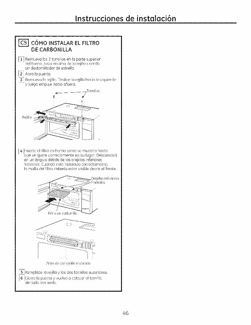
IC51 COMO INSTALAR EL FILTRODE CARBONILLA
[_ Remueva los 2 tornillos en la parte superiordel homo, justo encima de la rejilla usandoun destornillador de estrella.
[_ Abra la puerta.
[_ Remueva la rejilla. Deslice la rejilla hacia la izquierday luego empuje hacia afuera.
i__ T°rnill°s
i
Rejillo__
[_lnserte el filtro en horno como se muestra hastaque se ajuste correctamente en su lugar. Descansar6en un 6ngulo detras de las orejillas inferioresfrontales. Cuando est6 instalado correctamente,la malla del filtro deber[a estar visible desde el frente.
.Orejillas inferiores
Filtro de carbonilla
Filtro de carbonilla instalado
_] Remploce Io rejillo y los dos tornillos superiores.
[_Cierre Io puerto y vuelv(] (] coloc(]r el tornillodel Iodo izquierdo.
46
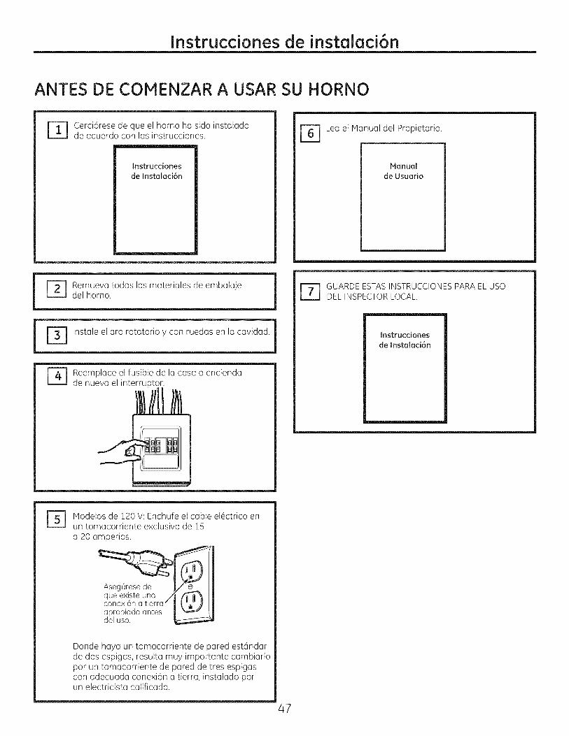
Instrucdonesde instalad6n
ANTES DE COIVIENZARA USAR SU HORNO
Cerci6rese de que el horno ha sido instaladode acuerdo con las instrucciones.
Instrucciones
de Instalaci6n
r_ emueva todos los materiales de embalajedel homo.
r_ Lea el Manual del Propietario.
Manual
de Usuario
! |
Instale el aro rotatorio y con ruedas en la cavidad. 1
Reemplece el fusible de la casa o enciendade nuevo el interruptor.
r_ UARDEESTASINSTRUCCIONESPARAEL USODEL INSPECTORLOCAL.
Instruccionesde Instalaci6n
B] Modelos de 120 V: Enchufe el cable el6ctrico enun tomacorriente exclusivo de !5a 20 amperios.
__lqueexiste
Aseg0resede /_
una /conexl6n a tlerra --apropiada antesdel uso.
Donde haya un tomacorriente de pared est6ndarde dos espigas, resulta muy importante cambiarlopor un tomacorriente de pared de tres espigascon adecuada conexi6n a tierra, instalado porun electricista calificado.
47

Printed in Korea
Impreso en Corea