stainless one-touch fittings series kg - smc … one-touch fittings series kg chuck seal ......
TRANSCRIPT
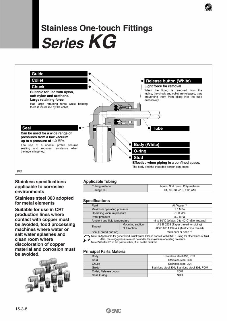
Stainless One-touch Fittings
Series KG
Chuck
Seal
Stud
Release button (White)
O-ring
Body (White)
Tube
Collet
Guide
Suitable for use with nylon, soft nylon and urethane.Large retaining force.Has large retaining force while holding force is increased by the collet.
Can be used for a wide range of pressures from a low vacuum up to a pressure of 1.0 MPaThe use of a special profile ensures sealing and reduces resistance when the tube is inserted.
Light force for removalWhen the fitting is removed from the tubing, the chuck and collet are released, thus preventing them from biting into the tube excessively.
Effective when piping in a confined space.The body and the threaded portion can rotate.
Applicable Tubing
PAT.
Specifications
Principal Parts Material
Stainless specifications applicable to corrosive environmentsStainless steel 303 adopted for metal elementsSuitable for use in CRT production lines where contact with copper must be avoided, food processing machines where water or salt water splashes and clean room where discoloration of copper material and corrosion must be avoided.
Tubing materialTubing O.D.
Nylon, Soft nylon, Polyurethaneø4, ø6, ø8, ø10, ø12, ø16
Fluid Air/Water (1)
1.0 MPa
3.0 MPa–5 to 60°C (Water: 0 to 40°C) (No freezing)
JIS B 0203 (Taper thread for piping)Mounting sectionNut section
With seal or none (2)
JIS B 0211 Class 2 (Metric fine thread)
Maximum operating pressure–100 kPaOperating vacuum pressure
Proof pressureAmbient and fluid temperature
Thread
Seal (Thread portion)Note 1) Applicable for general industrial water. Please consult with SMC if using for other kinds of fluid.
Also, the surge pressure must be under the maximum operating pressure.Note 2) Suffix “S” to the part number, if w/ seal is desired.
Body Stainless steel 303, PBTStainless steel 303Stainless steel 304
Stainless steel 304, Stainless steel 303, POMPOM
StudChuckGuideCollet, Release button
NBRSeal, O-ring
15-3-8
Hex. socket head male connector
P. 10KGS
Universal male elbow
P. 12KGV
Male connector
P. 10KGH
Bulkhead union
Extended male elbow
P. 14
P. 18
Bulkhead connector
P. 18
Male elbow
P. 11
P. 13
P. 13
P. 15
KGL
Male branch tee
KGT
KGE
KGW
KGE
Female connector
P. 11KGF
Union elbow
KGL
Union tee
KGT
Straight union
P. 11KGH
Plug-in elbow
KGL
Different diameter tee
KGT
Different diameter straight
P. 11KGH
Male delta union
KGD
Male run tee
KGY
Male branch connector
P. 12 P. 16 P. 17
P. 17
P. 15
P. 15
P. 14
P. 14
KGLU
Delta union
KGD
Different dia. double union “Y”
KGUD
P. 16
Branch union elbow
P. 13KGLU
Delta branch
KGUD
Union “Y”
KGU
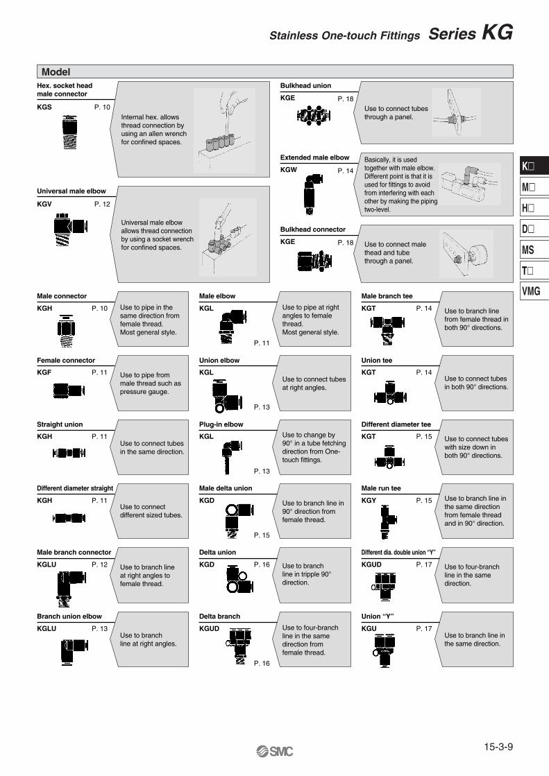
Universal male elbowallows thread connectionby using a socket wrenchfor confined spaces.
Use to pipe in the same direction from female thread.Most general style.
Use to pipe at right angles to female thread.Most general style.
Use to branch line from female thread in both 90° directions.
Use to connect tubes with size down in both 90° directions.
Use to branch line in the same direction from female thread and in 90° direction.
Use to branch line in the same direction.
Use to four-branch line in the same direction.
Use to connect tubes in both 90° directions.
Use to connect tubes at right angles.
Use to change by 90° in a tube fetching direction from One-touch fittings.
Use to branch line in 90° direction from female thread.
Use to branch line in tripple 90° direction.
Use to four-branch line in the same direction from female thread.
Use to pipe from male thread such as pressure gauge.
Use to connect different sized tubes.
Use to branch line at right angles to female thread.
Use to branch line at right angles.
Use to connect tubes in the same direction.
Model
Internal hex. allowsthread connection by using an allen wrench for confined spaces.
Use to connect tubes through a panel.
Basically, it is used together with male elbow. Different point is that it is used for fittings to avoid from interfering with each other by making the piping two-level.
Use to connect male thead and tube through a panel.
15-3-9
Stainless One-touch Fittings Series KG
K�
M�
H�
D�
MS
T�
VMG
Different dia. union “Y”
P. 17KGU
Tube cap
KGC
Branch
P. 16KGU
Plug-in reducer
P. 17KGR P. 18Use to connect tubes in the same direction, reducing the size of tubes.
Use to change size of One-touch fittings.
Use to plug unused tubing.
Use to branch line in the same direction from the female thread.
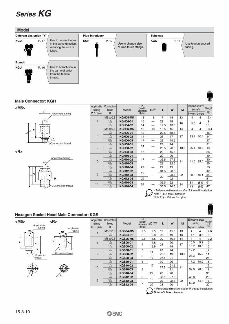
Applicabletubing
O.D. (mm)
4
6
8
10
12
Connectionthread
RModel L A∗ M
Effective area(mm2)
Nylon Urethane
Weight(g)
M5 x 0.8
M5 x 0.8
1 8
1 81 41 81 43 81 81 4
1 43 8
KGS04-M5KGS04-01KGS06-M5KGS06-01KGS06-02KGS08-01KGS08-02KGS08-03KGS10-01KGS10-02
KGS12-02KGS12-03
2.5 192320
24
2825.527.530
27.5
33.52928
øD
9.5 9.811.511.813.8
14
17
19
22
15.5 131619
16.52018
17
2419.5212621.5
27.522.5
3 2.5
4
5
6
517
8
8
4 4.1 4
10.7
23.3
17.2
39.0
60.0
46.0
4 2.6 8 3.6
4
10.010.0 9.9
16.2
26.6
17.2 10.0
44.5
14
18.5
21
22
3.2 9151211241812
3 8 KGS10-03 21 191 2 KGS10-04 2822 20 35
2318
1 2 KGS12-04 2010
30∗ Reference dimensions after R thread installation.
Note)
Note) øD: Max. diameter
Applicabletubing
O.D. (mm)
4
6
8
10
12
16
Connectionthread
RModel L A∗ M
Effective area (2)
(mm2)
Nylon Urethane
Weight(g)
M5 x 0.8
M5 x 0.8
1 8
1 81 4
1 81 43 81 81 4
1 43 8
KGH04-M5KGH04-01
KGH06-M5KGH06-01KGH06-02
KGH08-01KGH08-02KGH08-03KGH10-01KGH10-02
KGH12-02KGH12-03
8 1722
18.522.523
2826.5223033.5
34.5
30
øD
8—
10——
—
—
—
14 13
1618
1518.517
2420.515.52627.5
28.5
39.5 3235.5 26.5
23.5
10
101214
14
17
17 —
19
22
4
5.6
4
13.1
26.1
41.5
58.3
4 2.4 916
4 1 4 KGH04-02 19.5— 13.5144
10.4
18.0
29.5
46.1
81 (81) 113 (96)
14
17
18.5
21
22
24
3.41614
3 8 KGH06-03 22— 15.517 272119261930
3 8 KGH10-03 29 22.5 301 2 KGH10-04 27— 19 53
4234
1 23 81 2
KGH12-04KGH16-03KGH16-04
2222
24 —
516147
(1)
Note 1) øD: Max. diameterNote 2) ( ): Values for nylon.
∗ Reference dimensions after R thread installation.
Male Connector: KGH
Hexagon Socket Head Male Connector: KGS
<M5>
<R>
<M5> <R>
Model
Applicable tubing
Connection thread
Applicable tubing
Connection thread
Connectionthread
Connection thread
Applicabletubing Applicable
tubing
H(widthacrossflats)
H(widthacrossflats)
Series KG
15-3-10
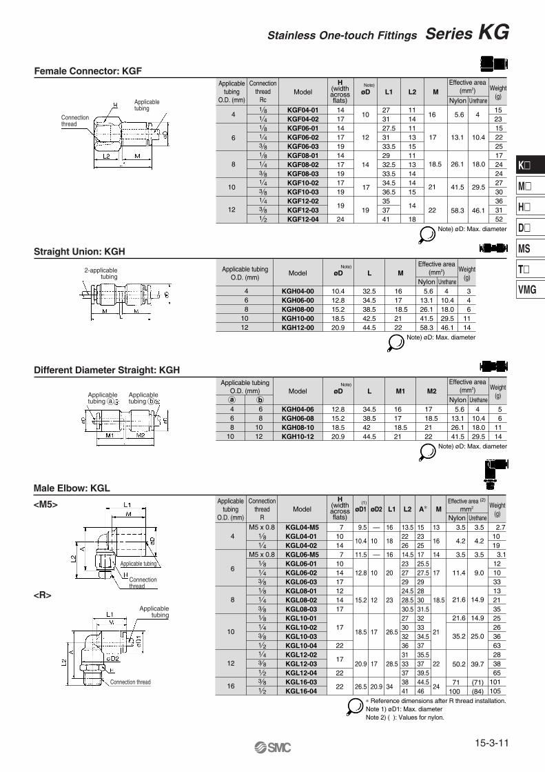
Applicabletubing
O.D. (mm)
4
6
8
10
12
16
Connectionthread
RModel
Effective area (2)
mm2
Nylon Urethane
Weight(g)
1 81 4
1 4
1 8
3 81 81 43 81 81 43 81 21 43 8
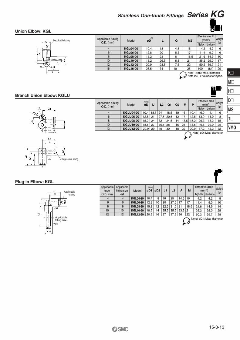
KGL04-M5KGL04-01KGL04-02KGL06-M5KGL06-01KGL06-02KGL06-03KGL08-01KGL08-02KGL08-03KGL10-01KGL10-02KGL10-03KGL10-04KGL12-02KGL12-03
7 9.5
10.4 10 18 16 4.2 4.2
3.5 3.5
2226
2325
— 16 13.5 15 13
øD1 øD2 L1 L2 A∗ M
11.4 9.0
1014 7 11.5
12.8 10 20
15.2 12 23
18.5
20.9 17 28.5
26.5 20.9 34 2438 44.541 46
22
17 26.5 21
17
18.5
— 16 14.5 1723 25.527 27.529 2924.5 2828.5 3030.5 31.527 3230 3332 34.536 3731 35.533 3737 39.5
14101417121417
17
22
17
3.5
21.6
50.2
3.5 2.7 10 19
14.9
21.6 14.9
35.2 25.0
39.7
3.1 12 10 33 13 21 35 25 26
28 38
71 (71) 101100 (84) 105
36 63
1 23 81 2
KGL12-04KGL16-03KGL16-04
22
22
65
M5 x 0.8
M5 x 0.8
(1)
Note 1) øD1: Max. diameterNote 2) ( ): Values for nylon.
∗ Reference dimensions after R thread installation.
Applicable tubingO.D. (mm)
6
Model L M1Effective area
(mm2)Nylon Urethane
Weight(g)
KGH04-06 34.5
øD
12.8 16 5.6 4 5 8 KGH06-08 38.515.2 17 13.1 10.4 610 KGH08-10 4218.5 18.5 26.1 18.0 1112 KGH10-12 44.520.9 21 41.5 29.5 14
4 6 810
M2
1718.52122
Note) øD: Max. diameter
Note)
a b
Applicable tubingO.D. (mm)
4
Model L MEffective area
(mm2)Nylon Urethane
Weight(g)
KGH04-00 32.5
øD
10.4 16 5.6 4 3 6 KGH06-00 34.512.8 17 13.1 10.4 4 8 KGH08-00 38.515.2 18.5 26.1 18.0 610 KGH10-00 42.518.5 21 41.5 29.5 1112 KGH12-00 44.520.9 22 58.3 46.1 14
Note)
Note) øD: Max. diameter
Applicabletubing
O.D. (mm)
4
6
8
10
12
Connectionthread
RcModel L1 L2 M
Effective area(mm2)
Nylon Urethane
Weight(g)
1 4
1 8
1 4
1 8
3 81 81 43 81 43 81 43 8
KGF04-01KGF04-02KGF06-01KGF06-02KGF06-03KGF08-01KGF08-02KGF08-03KGF10-02KGF10-03KGF12-02KGF12-03
14 273127.53133.52932.533.534.536.5353741
øD
10
12
14
19
1116
14111315
17 13.1 10.4
1113141415
14
171417191417191719
17
19
5.6
26.1
58.3
4 1523
18.0
41.5 29.5
46.1
18.5
21
22
15222517242427303631
1 2 KGF12-04 1824 52
Note)
Note) øD: Max. diameter
Female Connector: KGF
Straight Union: KGH
<M5>
<R>
Male Elbow: KGL
Different Diameter Straight: KGH
Applicabletubing
Connectionthread
2-applicabletubing
Applicabletubing
Applicabletubing
Connectionthread
Connection thread
Applicable tubing
Applicabletubing
a b
H(widthacrossflats)
H(widthacrossflats)
15-3-11
Stainless One-touch Fittings Series KG
K�
M�
H�
D�
MS
T�
VMG
Applicabletubing
O.D. (mm)
4
6
8
10
12
Connectionthread
RModel
Effective area(mm2)
Nylon Urethane
Weight(g)
1 8
1 4
1 8
1 81 43 81 43 83 81 2
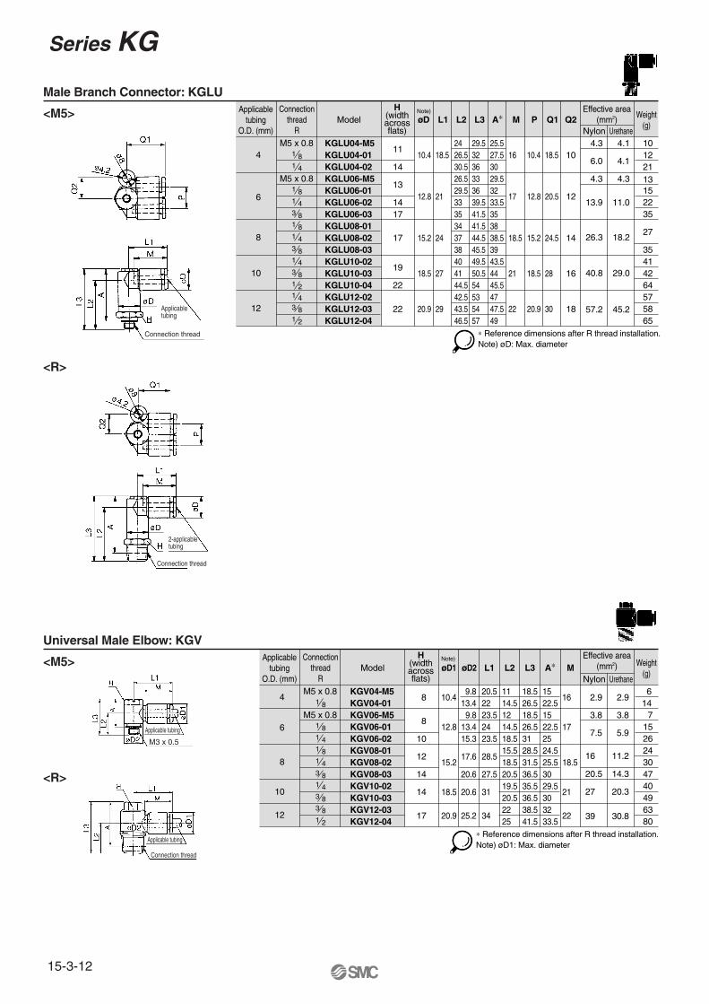
KGV04-M5KGV04-01KGV06-M5KGV06-01KGV06-02KGV08-01KGV08-02KGV08-03KGV10-02KGV10-03KGV12-03KGV12-04
10.413.4 22
16
3.8 3.814.5 22.5
9.8 20.5 11 15
øD1 øD2 L1 L2 A∗ M
7.5 5.9
8
12.815.3 23.5
15.217.6
20.6
28.5
27.5
18.5
20.9 25.2 34 22
20.6 31 21
17
18.5
9.813.4
23.524
12 1514.5 22.518.5 2515.518.5
24.525.5
20.5 3019.520.5
29.530
2225
3233.5
26.518.5
L3
18.526.53128.531.536.535.536.538.541.5
8
10
12
14
14
17
2.9
16
39
2.9 614
11.2
27 20.3
20.5 14.3
30.8
7152624304740496380
∗ Reference dimensions after R thread installation.Note) øD1: Max. diameter
M5 x 0.8
M5 x 0.8
Note)
Applicabletubing
O.D. (mm)
4
6
8
10
12
Connectionthread
RModel
Effective area(mm2)
Nylon Urethane
Weight(g)
1 81 4
1 4
1 8
3 81 81 43 81 43 81 21 43 8
KGLU04-M5KGLU04-01KGLU04-02KGLU06-M5KGLU06-01KGLU06-02KGLU06-03KGLU08-01KGLU08-02KGLU08-03KGLU10-02KGLU10-03KGLU10-04KGLU12-02KGLU12-03
1110.4 18.5
2426.530.5
29.53236
25.527.5 16 10.4 18.5 1030
26.5 33 29.529.5 36 3233 39.5 33.535 41.5 3534 41.5 3837 44.5 38.538 45.5 3940 49.5 43.541 50.5 4444.5 54 45.542.5 53 4743.5 54 47.546.5 57 49
6.0 4.1
4.3 4.3
øD L1 L2 L3 A∗ M P Q1 Q2
13.9 11.0
14
1312.8 21 17 12.8 20.5 12
15.2 24 18.5 15.2 24.5 14
18.5 27 21 18.5 28 16
20.9 29 22 20.9 30 18
1417
17
19
22
4.3
26.3
57.2
4.1
18.2
40.8 29.0
45.2
2113
1210
152235
27
3541
5758
4264
1 2 KGLU12-0422
65∗ Reference dimensions after R thread installation.
M5 x 0.8
M5 x 0.8
Note)
Note) øD: Max. diameter
Male Branch Connector: KGLU
<M5>
<R>
Universal Male Elbow: KGV
<M5>
<R>
Applicabletubing
Connection thread
Connection thread
2-applicabletubing
Connection thread
Applicable tubing
M3 x 0.5
Applicable tubing
H(widthacrossflats)
H(widthacrossflats)
Series KG
15-3-12
Applicabletube
O.D. mm
6 4
10 8
12
Applicablefitting size
ød
6 4
10 8
12
Model
KGL10-99
øD1
1416
øD2 MWeight
(g)
Effective area(mm2)
UrethaneNylon
2528
KGL06-99KGL08-99 21.6 14.9
11.4 9.0 4.2 4.2
50.2 39.735.2 25.0
1410 8
KGL12-99
KGL04-99 81012
25.527
L1
182022.5
35.537.5
L2
25 27.531.5
23.526
A
14.51721
2122
161718.5
18.520.9
10.412.815.2
Note)
Note) øD1: Max. diameter
Applicable tubingO.D. (mm)
ModelEffective area
(mm2)Nylon Urethane
Weight(g)
KGLU04-00
øD
10.4 6.0 4.1 6KGLU06-00 12.8 13.9 11.0 8KGLU08-00 15.2 26.3 18.2 15KGLU10-00 18.5 40.8 29.0 25
4 6 810
KGLU12-00 20.9 57.2 45.2 3212
L1
18.521242729
L2
2427.53236.540
Q1
18.520.524.52830
Q2
1012141618
M
161718.52122
P
10.412.815.218.520.9
Note)
Note) øD: Max. diameter
Applicable tubingO.D. (mm)
Model L QEffective area (2)
(mm2)
Nylon Urethane
Weight(g)
KGL04-00 18
øD
10.4 4.5 4.2 4.2 6KGL06-00 2012.8 5.3 11.4 9.0 6KGL08-00 2315.2 6 21.6 14.9 10KGL10-00 26.518.2 6.8 35.2 25.0 17
4 6 810
M2
161718.521
KGL12-00 28.520.9 7.5 50.2 39.7 2112 22KGL16-00 3426.5 10 100 (84) 2916 25
(1)
Note 1) øD: Max. diameterNote 2) ( ): Values for nylon.
Union Elbow: KGL
Branch Union Elbow: KGLU
Plug-in Elbow: KGL
2-applicable tubing
3-applicable tubing
Applicabletubing
Applicable fitting sizeød
15-3-13
Stainless One-touch Fittings Series KG
K�
M�
H�
D�
MS
T�
VMG
Applicabletubing O.D.
(mm)
4
6
16
8
10
12
Connectionthread
R
1 8
1 8
1 81 4
1 43 8
1 43 8
Model
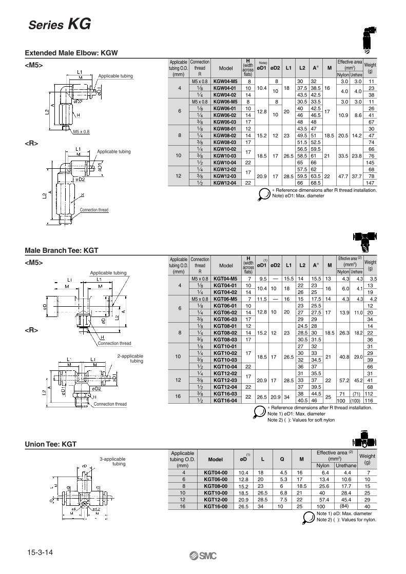
KGT04-M5KGT04-01
KGT06-M5KGT06-01
KGT08-01KGT08-02
KGT10-02KGT10-03
KGT12-02KGT12-03
7
15.2
18.5
20.9
7
17
17
øD1
10 1810.4
10 2012.8
øD2
1422
1523
24.528.5
3032
3133
12
—
—
17
17
12 23
26.5
28.5
L1
18.5
21
22
M
13.9
26.3
40.8
57.2
11.0
18.2
29.0
45.2
L2
15.523
17.5
9.5
11.5
15.5
16
13
1425.5
2830
3334.5
35.537
A∗ Weight(g)
Effective area (2)
(mm2)
3.5 4.3 4.3
6.0 4.116
Nylon Urethane
131 4 KGT04-02 26 25 19
4.2 12
14 22
29
10
1 8 KGT10-01 27 32 31
1 4
3 8
KGT06-02
KGT08-03 17
22
22
22
27
30.5
27.5 17
31.5
203 8 KGT06-03 29 29 34
36
391 2 KGT10-04 36 37 66
31 41
1 2 KGT12-04 37 39.5
4.3 4.3
683 8 KGT16-03
26.538
20.9 34 25 71 (71) 100 (100)
44.5 1121 2 KGT16-04 40.5 46 116
∗ Reference dimensions after R thread installation.
M5 x 0.8
M5 x 0.81410
1714
14
(1)
Note 1) øD1: Max. diameterNote 2) ( ): Values for soft nylon
Applicabletubing O.D.
(mm)
6 4
10 8
1612
Model
KGT04-00KGT06-00
KGT10-00KGT12-00
øD
26.520.9
1820
26.528.5
M
100 (84)
L
4.5 5.3
6.8
10.4
18.515.212.8
16
21 7.5
QWeight
(g)
Effective area (2)
(mm2)
7 6.4 4.4Nylon Urethane
10KGT08-00 23 6 15
2529
KGT16-00 34 10 25 40
40 28.4 57.4 45.4
18.5
22
25.6 17.717 13.4 10.6
(1)
Note 1) øD: Max. diameterNote 2) ( ): Values for nylon.
Applicabletubing O.D.
(mm)
4
6
8
10
12
Connectionthread
R
1 8
1 8
1 81 4
1 43 8
1 43 8
Model
KGW04-M5KGW04-01
KGW06-M5KGW06-01
KGW08-01KGW08-02
KGW10-02KGW10-03
KGW12-02KGW12-03
810.4
12.8
15.2
18.5
20.9
8
17
17
øD1
10
10
øD2
183037.5
30.540
43.549.5
56.558.5
57.559.5
20
12
8
8
17
17
12 23
26.5
28.5
L1
16
17
18.5
21
22
M
10.9
20.5
33.5
47.7
8.6
14.2
23.8
37.7
L2
3238.5
33.542.5
4751
59.561
6263.5
A∗ Weight(g)
Effective area(mm2)
11 3.0 3.0
4.0 4.0
Nylon Urethane
231 4 KGW04-02 43.5 42.5 38
1126
3047
66
101 4
3 8
KGW06-02
KGW08-03 17
22
22
46
51.5
46.5
52.5
413 8 KGW06-03 48 48 67
74
761 2 KGW10-04 65 66 145
6878
1 2 KGW12-04 66 68.5
3.0 3.0
147∗ Reference dimensions after R thread installation.
M5 x 0.8
M5 x 0.81410
1714
14
Note)
Note) øD1: Max. diameter
Extended Male Elbow: KGW
<M5>
<R>
Male Branch Tee: KGT
<M5>
<R>
Union Tee: KGT
Applicable tubing
Applicable tubing
Connection thread
Connection thread
Connection thread
3-applicabletubing
Applicable tubing
2-applicabletubing
M5 x 0.8
H(widthacrossflats)
H(widthacrossflats)
Series KG
15-3-14

Applicabletubing O.D.
(mm)
4
6
8
10
12
Connectionthread
R
1 8
1 8
1 81 4
1 43 8
1 43 8
Model
KGD04-M5KGD04-01
KGD06-M5KGD06-01
KGD08-01KGD08-02
KGD10-02KGD10-03
KGD12-02KGD12-03
11
15.2
18.5 26.5
22 20.9 28.5
13
19
øD
2426.5
2629
33.536.5
39.540.5
4243
23.5
L1
21
22
M
13.9
40.8
57.2
11.0
18.5 26.3 18.2
29.0
45.2
L2
25.527.5
28.5
10.4
12.8
18.5
20.5
16
1731.5
3738
4343.5
46.547
A∗ Weight(g)
Effective area(mm2)
10 4.3 4.3
6.0 6.0
Nylon Urethane
121 4 KGD04-02 30.5 30 21
1214
26
39
1 4
3 8
KGD06-02
KGD08-03
22
32.5
37.5
33
12.8
13.9
Q
11.1
8.7
9.9
38.5
213 8 KGD06-03 34.5 34.5 34
35
401 2 KGD10-04 44 45 62
5556
1 2 KGD12-04 46 48.5
4.3 4.3
63
M5 x 0.8
M5 x 0.814
1714
17
Note)
Note) øD: Max. diameter∗ Reference dimensions after R thread installation.
Applicabletubing O.D.
(mm)
4
6
16
8
10
12
Connectionthread
R
1 8
1 8
1 81 4
1 43 8
1 43 8
Model
KGY04-M5KGY04-01
KGY06-M5KGY06-01
KGY08-01KGY08-02
KGY10-02KGY10-03
KGY12-02KGY12-03
7
15.2
18.5
20.9
7
17
17
øD1
10 18 —10.4
10 2012.8
øD2
13.522
14.5 17.523
24.528.5
3032
3133
12
—
—
17
17
12 23
26.5
28.5
L1
18.5
21
22
M
13.4
25.6
40.0
57.4
10.6
17.7
17 13.4 10.6
28.4
45.4
L2
25.536
29
9.5
11.5
16
17.5
13
1439
43.545.5
50.552
53.555
A∗ Weight(g)
Effective area (2)
(mm2)
3.5 4.6 4.6
6.4 4.416
Nylon Urethane
131 4 KGY04-02 26 38 19
4.3 12
14 22
29
10
1 8 KGY10-01 27
15
L3
—49.5 31
1 4
3 8
KGY06-02
KGY08-03 17
22
22
22
27
30.5
41 17
47
203 8 KGY06-03 29 42.5 34
36
391 2 KGY10-04 36 54.5 66
31 41
1 2 KGY12-04 37 57.5
4.6 4.6
683 8 KGY16-03
26.538
20.9 34 25 81 (81) 113 (113)
65.5 1121 2 KGY16-04 41 67 116
M5 x 0.8
M5 x 0.81410
1714
14
(1)
Note 1) øD1: Max. diameterNote 2) ( ): Values for nylon.
∗ Reference dimensions after R thread installation.
Applicable tubingO.D. (mm)
4
8 6
10
6
10 8
12
Model
KGT08-10
øD1
26.528.5
L1 M1Weight
(g)
Effective area(mm2)
UrethaneNylon
1421
KGT04-06KGT06-08 16.4 16.4
7.1 6.5
56 44.536 27.2
8 5
KGT10-12
19.522.5
23 26.5
L2
18 20
6 6.8
Q
4.55.3
21 22
17 18.5
18.520.9
12.815.2
øD2
15.218.5
10.412.8
M2
18.521
16 17
Note)
Note) øD1: Max. diameter
Different Diameter Tee: KGT
Male Run Tee: KGY
Male Delta Union: KGD
<M5>
<R>
<M5>
<R>
a b
Applicable tubing
2-applicable tubing
Connection thread
Connection thread
Applicable tubing
Applicable tubing
2-applicable tubing
Connectionthread
2-applicabletubing
Connectionthread
2-applicabletubing
H(widthacrossflats)
H(widthacrossflats)
15-3-15
Stainless One-touch Fittings Series KG
K�
M�
H�
D�
MS
T�
VMG

Applicabletubing
O.D. (mm)
Connectionthread
RModel A∗ M Weight
(g)
1 8
1 81 43 81 8
KGU04-01KGU04-M5
KGU06-M5KGU06-01KGU06-02KGU06-03KGU08-01
1 4 KGU08-023 8 KGU08-031 4 KGU10-023 8 KGU10-031 2 KGU10-041 4 KGU12-023 8 KGU12-031 2 KGU12-04
4
6
8
10
12
M5 x 0.8
M5 x 0.8
øD
10.4
12.8
15.2
18.5
20.9
1116
17
21
22
18.5
2.2
4.2
2.2
13.4
2.2
4.2
2.2
10.6
1 4 KGU04-02 14
13
1417
17
19
22
22
Nylon Urethane
Effective area(mm2)
4112012112134
L
39.5424642.545.5495152.555.556.5
64.565.568.5
616265
P
10.4363840
12.8
15.2
18.5
20.9
3941.54344.548.549.5505555.55758.55960.5
25.6 17.7152335
40 28.4304065
57.4 45.4324065
Note)
Note) øD: Max. diameter∗ Reference dimensions after R thread installation.
Applicabletubing
O.D. (mm)Model
6 810
4
MEffective area
(mm2) Weight(g)
KGD06-00KGD04-00
øD
10.4 18.5 16 12.8 20.5 17 15.2 23.5 18.518.5 26.5 21
6.013.926.340.8
4.1
Nylon Urethane
11.018.229.0
5 71119
KGD08-00KGD10-00
L
8.7 9.911.112.8
12 20.9 28.5 22 57.2 45.2 24KGD12-00 13.9
QNote)
Note) øD: Max. diameter
Delta Union: KGD
Branch “Y”: KGU
<M5>
<R>
Delta Branch: KGUDApplicable
tubingO.D. (mm)
Connectionthread
RModel A∗ P Weight
(g)
1 8
1 81 4
KGUD04-01
KGUD06-01KGUD06-02
4
6
øD1
10.4
12.8
øD2
12.8
15.2
1310.4
12.8
M
16
17
Q
9.7
11.7
4.2
13.4
4.2
10.6
1 4 KGUD04-02 14
17
Nylon Urethane
Effective area(mm2)
1725
29
L
43.547 50.553.5
I
2139.541
26 46.547.5
Note)
∗ Reference dimensions after R thread installation.Note) øD1: Max. diameter
3-applicabletubing
2-applicabletubing
Connection thread
Connectionthread
2-applicabletubing
Connection thread
4-applicable tubing
H(widthacrossflats)
H(widthacrossflats)
Series KG
15-3-16
Applicabletubing
O.D. (mm)
Applicablefitting size
ødModel A M Weight
(g)
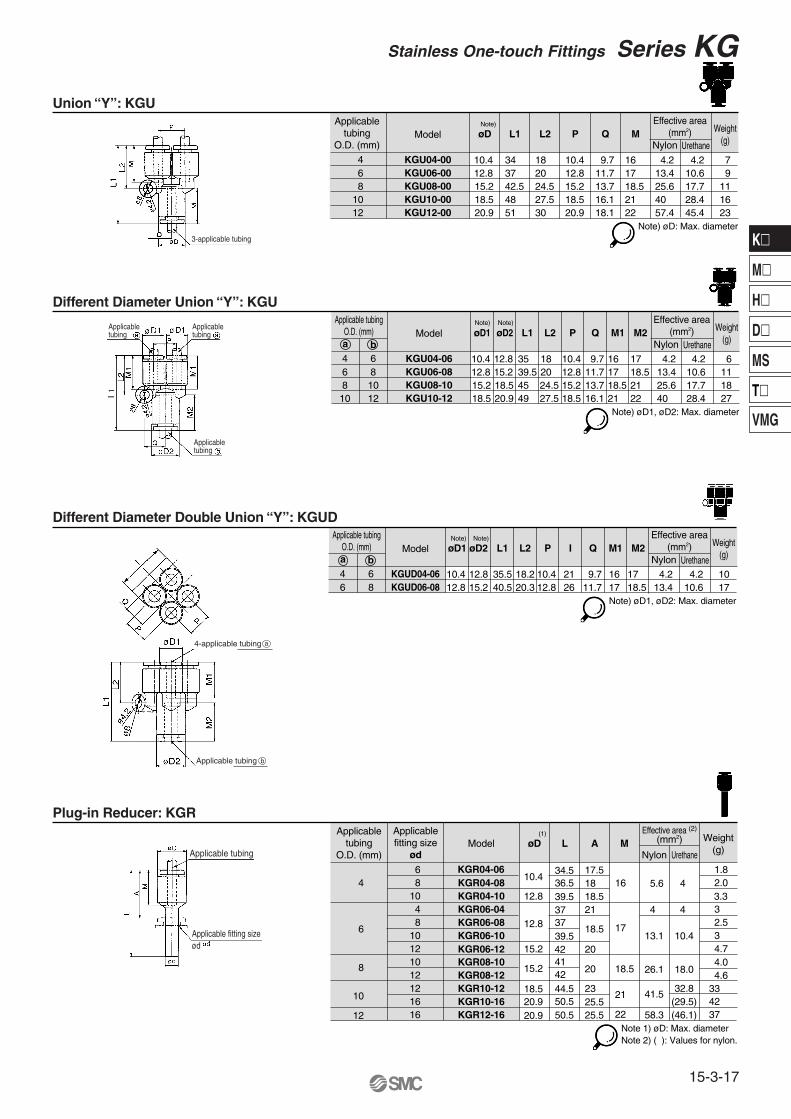
KGR04-08KGR04-06
KGR06-04KGR06-08KGR06-10KGR06-12KGR08-10KGR08-12KGR10-12KGR10-16KGR12-16
4 6 810 4 810121012121616
6
8
10
12
øD
10.4
12.8
12.8
15.2
15.2
18.520.920.9
16
17
22
18.5
21
5.6
4
13.1
4
4
10.4
KGR04-10
Nylon Urethane
Effective area (2)
(mm2)
1.8 2.0 3.3 3 2.5 3 4.7
L
34.536.539.5373739.542414244.550.550.5
17.51818.521
18.5
20
20
2325.525.5
26.1
41.5
18.0
32.8(29.5)
4.0 4.633
58.3 (46.1)4237
(1)
Note 1) øD: Max. diameterNote 2) ( ): Values for nylon.
Applicable tubingO.D. (mm) Model
6810
4
M1Effective area
(mm2) Weight(g)
KGU06-08KGU04-06
øD1
10.4 18 16 12.8 20 17 15.2 24.5 18.518.5
øD2
12.815.218.520.9 27.5 21
M2
17 18.521 22
4.213.425.640
4.2
Nylon Urethane
10.617.728.4
6111827
KGU08-10KGU10-12
L2
9.711.713.716.1
81012
6 35 39.545 49
L1 Q
10.412.815.218.5
PNote) Note)
Note) øD1, øD2: Max. diameter
a b
Applicabletubing
O.D. (mm)Model
6 810
4
MEffective area
(mm2) Weight(g)
KGU06-00KGU04-00
øD
10.4 18 1612.8 20 1715.2 24.5 18.518.5 27.5 21
4.213.425.640
4.2
Nylon Urethane
10.617.728.4
7 91116
KGU08-00KGU10-00
L2
9.711.713.716.1
12 20.9 30 22 57.4 45.4 23KGU12-00 18.1
343742.548
L1
51
Q
10.412.815.218.520.9
PNote)
Note) øD: Max. diameter
Union “Y”: KGU
Different Diameter Union “Y”: KGU
Plug-in Reducer: KGR
Different Diameter Double Union “Y”: KGUDApplicable tubing
O.D. (mm) Model
64
M1Effective area
(mm2) Weight(g)
KGUD06-08KGUD04-06
øD1
10.4 18.2 1612.8 20.3 17
øD2
12.815.2
M2
17 18.5
4.213.4
4.2
Nylon Urethane
10.61017
L2
9.711.78
6 35.540.5
L1 Q
10.412.8
P
2126
INote) Note)
Note) øD1, øD2: Max. diameter
a b
3-applicable tubing
Applicabletubing
Applicabletubing
Applicabletubing
Applicable tubing
Applicable fitting size ød
4-applicable tubing a
Applicable tubing b
15-3-17
Stainless One-touch Fittings Series KG
K�
M�
H�
D�
MS
T�
VMG
Applicable tubingO.D. (mm)
Model
6 810
4
M Weight(g)
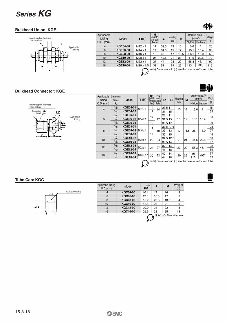
KGC06-00KGC04-00
øD
10.4 17 1612.8 18.5 1715.2 20.5 18.518.5 23 21
3346
KGC08-00KGC10-00
12 20.9 24 22 8KGC12-0016 26.5 28 25 13KGC16-00
L
Note) øD: Max. diameter
Note)
Applicabletubing
O.D. (mm)
Connectionthread
RcModel M Weight
(g)
1 8
1 81 43 81 8
KGE04-01
KGE06-01KGE06-02KGE06-03KGE08-01
1 4 KGE08-023 8 KGE08-031 4 KGE10-023 8 KGE10-033 8 KGE12-031 2 KGE12-04
4
6
8
10
12
16
1416
17
21
22
18.5
5.6
13.1
4
10.4
1 4 KGE04-02 17
17
17
19
19
22
24
30
14
17
19
24
27
32
T (M)
M12 x 1
M14 x 1
M16 x 1
M20 x 1
M22 x 1
M28 x 1.5
Nylon Urethane
Effective area (1)
(mm2)
1635
30
29
L1
27.5312831.533.527.533
15
3718
35
41
34.536.5
L2
1115111517 7.513
14
12.514
Mountinghole
13
15
17
21
23
29
Note) Dimensions in ( ) are the case of soft nylon tube.
26.1 18.0282748
41.5 29.55367
58.3 46.1
25 96113
(96)
9259
3 8 KGE16-03 1440 1271 2 KGE16-04 1844 132
Applicabletubing
O.D. (mm)Model
6 810
4
MEffective area (1)
(mm2) Weight(g)
KGE06-00KGE04-00 14 32.5 16
17 34.5 1719 38 18.524 42.5 21
5.6 13.1 26.1 41.5
4
Nylon Urethane
10.418.029.5
26 33 52 70
KGE08-00KGE10-00
L
13151721
12 27
T (M)
M12 x 1M14 x 1M16 x 1M20 x 1M22 x 1 44 22 58.3 46.1 90KGE12-00 23
16 32M28 x 1.5 51 25 113 (96) 115KGE16-00 29
Mountinghole
Note) Dimensions in ( ) are the case of soft nylon tube.
Bulkhead Union: KGE
Bulkhead Connector: KGE
Tube Cap: KGC
Mounting plate thickness11 mm or less
Applicabletubing
Applicabletubing
Mounting plate thickness7 mm or less
Connectionthread
Applicable tubing
H(widthacrossflats)
H1(widthacrossflats)
H2(widthacrossflats)
Series KG
15-3-18
Safety Instructions
These safety instructions are intended to prevent a hazardous situation and/or equipment damage. These instructions indicate the level of potential hazard by labels of "Caution", "Warning" or "Danger". To ensure safety, be sure to observe ISO 4414 Note 1), JIS B 8370 Note 2) and other safety practices.
1. The compatibility of pneumatic equipment is the responsibility of the person who designs the pneumatic system or decides its specifications.Since the products specified here are used in various operating conditions, their compatibility for the specific pneumatic system must be based on specifications or after analysis and/or tests to meet your specific requirements. The expected performance and safety assurance will be the responsibility of the person who has determined the compatibility of the system. This person should continuously review the suitability of all items specified, referring to the latest catalog information with a view to giving due consideration to any possibility of equipment failure when configuring a system.
2. Only trained personnel should operate pneumatically operated machinery and equipment.Compressed air can be dangerous if an operator is unfamiliar with it. Assembly, handling or repair of pneumatic systems should be performed by trained and experienced operators.
3. Do not service machinery/equipment or attempt to remove components until safety is confirmed.1. Inspection and maintenance of machinery/equipment should only be performed once measures to
prevent falling or runaway of the driver objects have been confirmed. 2. When equipment is to be removed, confirm the safety process as mentioned above. Cut the supply
pressure for this equipment and exhaust all residual compressed air in the system.3. Before machinery/equipment is restarted, take measures to prevent shooting-out of cylinder piston
rod, etc.
4. Contact SMC if the product is to be used in any of the following conditions:1. Conditions and environments beyond the given specifications, or if product is used outdoors.2. Installation on equipment in conjunction with atomic energy, railway, air navigation, vehicles,
medical equipment, food and beverages, recreation equipment, emergency stop circuits, clutch and brake circuits in press applications, or safety equipment.
3. An application which has the possibility of having negative effects on people, property, or animals, requiring special safety analysis.
Note 1) ISO 4414: Pneumatic fluid power--General rules relating to systems.
Note 2) JIS B 8370: General Rules for Pneumatic Equipment
Warning
Caution : Operator error could result in injury or equipment damage.
Warning : Operator error could result in serious injury or loss of life.
Danger : In extreme conditions, there is a possible result of serious injury or loss of life.
15-18-3
1. Confirm the specifications.Products represented in this catalog are designed for use in compressed air appllications only (including vacuum), unless otherwise indicated.Do not use the product outside their design parameters.Please contact SMC when using the products in applications other than compressed air (including vacuum).
4. Use clean airIf the compressed air supply is contaminated with chemicals, cynthetic materials, corrosive gas, etc., it may lead to break down or malfunction.
Selection
Mounting
Piping
Air Supply
Maintenance
Operating Environment
Warning
1. Instruction manualInstall the products and operate them only after reading the instruction manual carefully and understanding its contents. Also keep the manual where it can be referred to as necessary.
2. Securing the space for maintenanceWhen installing the products, please allow access for maintenance.
3. Tightening torqueWhen installing the products, please follow the listed torque specifications.
Warning
1. Do not use in environments where the product is directly exposed to corrosive gases, chemicals, salt water, water or steam.
2. Do not expose the product to direct sunlight for an extended period of time.
3. Do not use in a place subject to heavy vibrations and/or shocks.
4. Do not mount the product in locations where it is exposed to radiant heat.
Warning
1. Maintenance procedures are outlined in the operation manual.Not following proper procedures could cause the product to malfunction and could lead to damage to the equipment or machine.
2. Maintenance workIf handled improperly, compressed air can be dangerous.Assembly, handling and repair of pneumatic systems should be performed by qualified personnel only.
3. Drain flushingRemove drainage from air filters regularly. (Refer to the specifications.)
4. Shut-down before maintenanceBefore attempting any kind of maintenance make sure the supply pressure is shut of and all residual air pressure is released from the system to be worked on.
5. Start-up after maintenance and inspectionApply operating pressure and power to the equipment and check for proper operation and possible air leaks. If operation is abnormal, please verify product set-up parameters.
6. Do not make any modifications to be product.Do not take the product apart.
Warning
1. Before pipingMake sure that all debris, cutting oil, dust, etc, are removed from the piping.
2. Wrapping of pipe tapeWhen screwing piping or fittings into ports, ensure that chips from the pipe threads or sealing material do not get inside the piping. Also, when the pipe tape is used, leave 1.5 to 2 thread ridges exposed at the end of the threads.
Caution
1. Operating fluidPlease consult with SMC when using the product in applications other than compressed air (including vacuum).Regarding products for general fluid, please ask SMC about applicable fluids.
2. Install an air dryer, aftercooler, etc.Excessive condensate in a compressed air system may cause valves and other pneumatic equipment to malfunction.Installation of an air dryer, after cooler etc. is recommended.
3. Drain flushingIf condensate in the drain bowl is not emptied on a regular basis, the bowl will over flow and allow the condensate to enter the compressed air lines.If the drain bowl is difficult to check and remove, it is recommended that a drain bowl with the auto-drain option be installed.For compressed air quality, refer to “Air Preparation Equipment” catalog.
Warning
Common PrecautionsBe sure to read before handling.For detailed precautions on every series, refer to main text.
15-18-4

Quality Assurance Information(ISO 9001, ISO 14001)
Reliable quality of products in the global market
To enable our customers throughout the world to use our products with even greater confidence, SMC has obtained certification for international standards “ISO 9001” and “ISO 14001”, and created a complete structure for quality assurance and environmental controls. SMC products pursue to meet its customers’ expectations while also considering company’s contribution in society.
This is an international standard for quality control and quality assurance. SMC has obtained a large number of certifications in Japan and overseas, providing assurance to our customers throughout the world.
Quality management system
ISO 9001
This is an international standard related to environmental management systems and environmental inspections. While promoting environmentally friendly automation technology, SMC is also making diligent efforts to preserve the environment.
Environmental management system
ISO 14001
Sales coordination
Production
Make customers our first priority, offering them reliable and friendly service.
Market researchProduct planningAfter service
Process controlInspection, testing, etc.Initial production control
Quality system educationTraining of suppliers
New product evaluationReliability designReliability testingNew technical development
EducationTraining
ResearchDesignDevelopment
Produce the highest quality with the participation of all employees.
Create new products using the latest technology, and offer the finest products in a timely manner.
SMC’s quality control system
Quality policies
Quality control activities
15-18-5
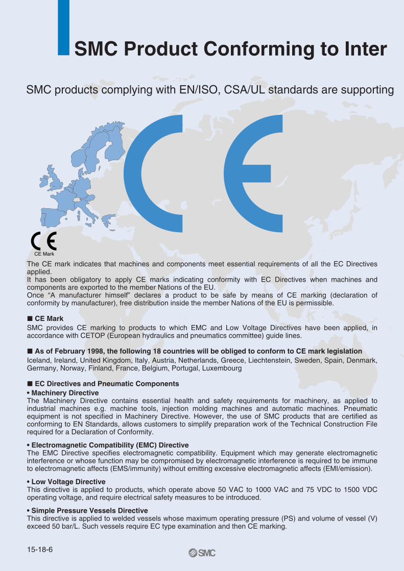
CE Mark
SMC Product Conforming to Inter
SMC products complying with EN/ISO, CSA/UL standards are supporting
The CE mark indicates that machines and components meet essential requirements of all the EC Directives applied.It has been obligatory to apply CE marks indicating conformity with EC Directives when machines and components are exported to the member Nations of the EU. Once “A manufacturer himself” declares a product to be safe by means of CE marking (declaration of conformity by manufacturer), free distribution inside the member Nations of the EU is permissible.
� CE MarkSMC provides CE marking to products to which EMC and Low Voltage Directives have been applied, in accordance with CETOP (European hydraulics and pneumatics committee) guide lines.
� As of February 1998, the following 18 countries will be obliged to conform to CE mark legislationIceland, Ireland, United Kingdom, Italy, Austria, Netherlands, Greece, Liechtenstein, Sweden, Spain, Denmark, Germany, Norway, Finland, France, Belgium, Portugal, Luxembourg
� EC Directives and Pneumatic Components• Machinery DirectiveThe Machinery Directive contains essential health and safety requirements for machinery, as applied to industrial machines e.g. machine tools, injection molding machines and automatic machines. Pneumatic equipment is not specified in Machinery Directive. However, the use of SMC products that are certified as conforming to EN Standards, allows customers to simplify preparation work of the Technical Construction File required for a Declaration of Conformity.
• Electromagnetic Compatibility (EMC) DirectiveThe EMC Directive specifies electromagnetic compatibility. Equipment which may generate electromagnetic interference or whose function may be compromised by electromagnetic interference is required to be immune to electromagnetic affects (EMS/immunity) without emitting excessive electromagnetic affects (EMI/emission).
• Low Voltage DirectiveThis directive is applied to products, which operate above 50 VAC to 1000 VAC and 75 VDC to 1500 VDC operating voltage, and require electrical safety measures to be introduced.
• Simple Pressure Vessels DirectiveThis directive is applied to welded vessels whose maximum operating pressure (PS) and volume of vessel (V) exceed 50 bar/L. Such vessels require EC type examination and then CE marking.
15-18-6
http://www.smcworld.com
you to comply with EC directives and CSA/UL standards.
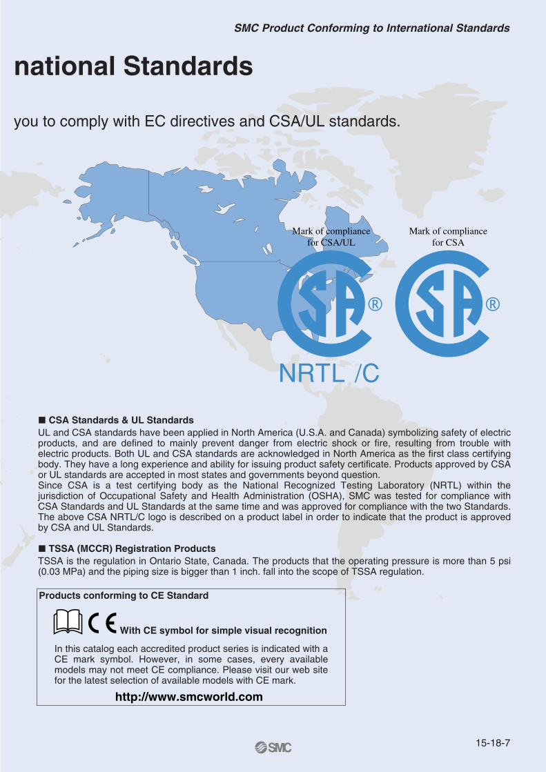
� CSA Standards & UL StandardsUL and CSA standards have been applied in North America (U.S.A. and Canada) symbolizing safety of electric products, and are defined to mainly prevent danger from electric shock or fire, resulting from trouble with electric products. Both UL and CSA standards are acknowledged in North America as the first class certifying body. They have a long experience and ability for issuing product safety certificate. Products approved by CSA or UL standards are accepted in most states and governments beyond question.Since CSA is a test certifying body as the National Recognized Testing Laboratory (NRTL) within the jurisdiction of Occupational Safety and Health Administration (OSHA), SMC was tested for compliance with CSA Standards and UL Standards at the same time and was approved for compliance with the two Standards. The above CSA NRTL/C logo is described on a product label in order to indicate that the product is approved by CSA and UL Standards.
� TSSA (MCCR) Registration Products TSSA is the regulation in Ontario State, Canada. The products that the operating pressure is more than 5 psi (0.03 MPa) and the piping size is bigger than 1 inch. fall into the scope of TSSA regulation.
Products conforming to CE Standard
With CE symbol for simple visual recognition
In this catalog each accredited product series is indicated with a CE mark symbol. However, in some cases, every available models may not meet CE compliance. Please visit our web site for the latest selection of available models with CE mark.
Mark of compliance for CSA
Mark of compliance for CSA/UL
national Standards
15-18-7
SMC Product Conforming to International Standards
America EuropeU.S.A. SMC Corporation of America3011 North Franklin Road Indianapolis, IN 46226, U.S.A.TEL: 317-899-4440 FAX: 317-899-3102
CANADA SMC Pneumatics (Canada) Ltd.6768 Financial Drive Mississauga, Ontario, L5N 7J6 CanadaTEL: 905-812-0400 FAX: 905-812-8686
MEXICO SMC Corporation (Mexico), S.A. DE C.V.Carr. Silao-Trejo K.M. 2.5 S/N, Predio San Jose del DuranzoC.P. 36100, Silao, Gto., MexicoTEL: 472-72-2-55-00 FAX: 472-72-2-59-44/2-59-46
CHILE SMC Pneumatics (Chile) S.A.Av. La Montaña 1,115 km. 16,5 P. Norte ParqueIndustrial Valle Grande, Lampa Santiago, ChileTEL: 02-270-8600 FAX: 02-270-8601
ARGENTINA SMC Argentina S.A.Teodoro Garcia 3860 (1427) Buenos Aires, ArgentinaTEL: 011-4555-5762 FAX: 011-4555-5762
BOLIVIA SMC Pneumatics Bolivia S.R.L.Avenida Beni Numero 4665Santa Cruz de la Sierra-Casilla de Correo 2281, BoliviaTEL: 591-3-3428383 FAX: 591-3-3449900
VENEZUELA SMC Neumatica Venezuela S.A. Apartado 40152, Avenida Nueva Granada, Edificio Wanlac,Local 5, Caracas 1040-A, VenezuelaTEL: 2-632-1310 FAX: 2-632-3871
PERU (Distributor) IMPECO Automatizacion Industrial S.A. AV. Canevaro 752, Lince, Lima, PeruTEL: 1-471-6002 FAX: 1-471-0935
URUGUAY (Distributor) BAKO S.A. Galicia 1650 esq. Gaboto C.P. 11200, Montevideo, UruguayTEL: 2-401-6603 FAX: 2-409-4306
BRAZIL SMC Pneumaticos Do Brasil Ltda.Rua. Dra. Maria Fidelis, nr. 130, Jardim Piraporinha-Diadema-S.P. CEP: 09950-350, BrasilTEL: 11-4051-1177 FAX: 11-4071-6636
COLOMBIA (Distributor) Airmatic Ltda.Calle 18 69-05 Apart. Aereo 081045 Santa Fe de Bogotá, ColombiaTEL: 1-424-9240 FAX: 1-424-9260
U.K. SMC Pneumatics (U.K.) Ltd.Vincent Avenue, Crownhill, Milton Keynes, MK8 0AN, Backinghamshire, U.K.TEL: 01908-563888 FAX: 01908-561185
GERMANY SMC Pneumatik GmbHBoschring 13-15 D-63329 Egelsbach, GermanyTEL: 06103-4020 FAX: 06103-402139
ITALY SMC Italia S.p.A.Via Garibaldi 62 I-20061 Carugate Milano, ItalyTEL: 02-9271365 FAX: 02-9271365
FRANCE SMC Pneumatique S.A.1 Boulevard de Strasbourg, Parc Gustave Eiffel, Bussy Saint Georges, F-77600Marne La Vallee Cedex 3 FranceTEL: 01-64-76-10-00 FAX: 01-64-76-10-10
SWEDEN SMC Pneumatics Sweden ABEkhagsvägen 29-31, S-141 05 Huddinge, SwedenTEL: 08-603-07-00 FAX: 08-603-07-10
SWITZERLAND SMC Pneumatik AGDorfstrasse 7, Postfach 117, CH-8484 Weisslingen, SwitzerlandTEL: 052-396-3131 FAX: 052-396-3191
AUSTRIA SMC Pneumatik GmbH (Austria)Girakstrasse 8, A-2100 Korneuburg, AustriaTEL: 0-2262-6228-0 FAX: 0-2262-62285
SPAIN SMC España, S.A.Zuazobidea 14 Pol. Ind. Júndiz 01015 Vitoria, SpainTEL: 945-184-100 FAX: 945-184-510
IRELAND SMC Pneumatics (Ireland) Ltd.2002 Citywest Business Campus, Naas Road, Saggart, Co. Dublin, IrelandTEL: 01-403-9000 FAX: 01-466-0385
NETHERLANDS (Associated company) SMC Pneumatics BVDe Ruyterkade 120, NL-1011 AB Amsterdam, NetherlandsTEL: 020-5318888 FAX: 020-5318880
GREECE (Distributor) S.Parianopoulos S.A.7, Konstantinoupoleos Street 11855 Athens, GreeceTEL: 01-3426076 FAX: 01-3455578
DENMARK SMC Pneumatik A/SKnudsminde 4 B DK-8300Odder, DenmarkTEL: 70252900 FAX: 70252901
SMC’s Global Service Network
15-18-20
EuropeFINLAND SMC Pneumatics Finland OYPL72, Tiistinniityntie 4, SF-02231 ESP00, FinlandTEL: 09-8595-80 FAX: 09-8595-8595
NORWAY SMC Pneumatics Norway A/SVollsveien 13C, Granfoss Næringspark N-1366 LYSAKER, NorwayTEL: 67-12-90-20 FAX: 67-12-90-21
BELGIUM (Distributor) SMC Pneumatics N.V./S.A.Nijverheidsstraat 20 B-2160 Wommelgem BelguimTEL: 03-355-1464 FAX: 03-355-1466
POLAND SMC Industrial Automation Polska Sp.z.o.o.ul. Konstruktorska 11A, PL-02-673 Warszawa, PolandTEL: 022-548-5085 FAX: 022-548-5087
TURKEY (Distributor) Entek Pnömatik San.ve Tic. Ltd. StiPerpa Tic. Merkezi Kat:11 No.1625 80270 Okmeydani Istanbul, TürkiyeTEL: 0212-221-1512 FAX: 0212-221-1519
RUSSIA SMC Pneumatik LLC.36/40 Sredny prospect V.O. St. Petersburg 199004, RussiaTEL: 812-118-5445 FAX: 812-118-5449
CZECH SMC Industrial Automation CZ s.r.o.Hudcova 78a, CZ-61200 Brno, Czech RepublicTEL: 05-4121-8034 FAX: 05-4121-8034
HUNGARY SMC Hungary Ipari Automatizálási kft.Budafoki ut 107-113 1117 BudapestTEL: 01-371-1343 FAX: 01-371-1344
ROMANIA SMC Romania S.r.l.Str. Frunzei, Nr. 29, Sector 2, Bucharest, RomaniaTEL: 01-3205111 FAX: 01-3261489
SLOVAKIA SMC Priemyselná automatizáciá, s.r.oNova 3, SK-83103 BratislavaTEL: 02-4445-6725 FAX: 02-4445-6028
SLOVENIA SMC Industrijska Avtomatilca d.o.o.Grajski trg 15, SLO- 8360 Zuzemberk, SloveniaTEL: 07388-5240 FAX: 07388-5249
SOUTH AFRICA (Distributor) Hyflo Southern Africa (Pty.) Ltd.P.O.Box 240 Paardeneiland 7420 South AfricaTEL: 021-511-7021 FAX: 021-511-4456
EGYPT (Distributor) Saadani Trading & Ind. Services15 Sebaai Street, Miami 21411 Alexandria, EgyptTEL: 3-548-50-34 FAX: 3-548-50-34
Oceania/AsiaAUSTRALIA SMC Pneumatics (Australia) Pty.Ltd.14-18 Hudson Avenue Castle Hill NSW 2154, AustraliaTEL: 02-9354-8222 FAX: 02-9894-5719
NEW ZEALAND SMC Pneumatics (New Zealand) Ltd.8C Sylvia Park Road Mt.Wellington Auckland, New ZealandTEL: 09-573-7007 FAX: 09-573-7002
TAIWAN SMC Pneumatics (Taiwan) Co.,Ltd.17, Lane 205, Nansan Rd., Sec.2, Luzhu-Hsiang, Taoyuan-Hsien, TAIWANTEL: 03-322-3443 FAX: 03-322-3387
HONG KONG SMC Pneumatics (Hong Kong) Ltd. 29/F, Clifford Centre, 778-784 Cheung, Sha Wan Road, Lai Chi Kok, Kowloon,Hong KongTEL: 2744-0121 FAX: 2785-1314
SINGAPORE SMC Pneumatics (S.E.A.) Pte. Ltd.89 Tuas Avenue 1, Jurong Singapore 639520TEL: 6861-0888 FAX: 6861-1889
PHILIPPINES SHOKETSU SMC CorporationUnit 201 Common Goal Tower, Madrigal Business Park,Ayala Alabang Muntinlupa, PhilippinesTEL: 02-8090565 FAX: 02-8090586
MALAYSIA SMC Pneumatics (S.E.A.) Sdn. Bhd.Lot 36 Jalan Delima1/1, Subang Hi-Tech Industrial Park, Batu 3 40000 Shah AlamSelangor, MalaysiaTEL: 03-56350590 FAX: 03-56350602
SOUTH KOREA SMC Pneumatics Korea Co., Ltd.Woolim e-BIZ Center (Room 1008), 170-5, Guro-Dong, Guro-Gu,Seoul, 152-050, South KoreaTEL: 02-3219-0700 FAX: 02-3219-0702
CHINA SMC (China) Co., Ltd.7 Wan Yuan St. Beijing Economic & Technological Development Zone 100176, China TEL: 010-67882111 FAX: 010-67881837
THAILAND SMC Thailand Ltd.134/6 Moo 5, Tiwanon Road, Bangkadi, Amphur Muang, Patumthani 12000, ThailandTEL: 02-963-7099 FAX: 02-501-2937
INDIA SMC Pneumatics (India) Pvt. Ltd.D-107 to 112, Phase-2, Extension, Noida, Dist. Gautaim Budh Nagar,U.P. 201 305, IndiaTEL: (0120)-4568730 FAX: 0120-4568933
INDONESIA (Distributor) P.T. Riyadi Putera MakmurJalan Hayam Wuruk Komplek Glodok Jaya No. 27-28 Jakarta 11180 IndonesiaTEL: 021-625 5548 FAX: 021-625 5888
PAKISTAN (Distributor) Jubilee CorporationFirst Floor Mercantile Centre, Newton Road Near Boulton Market P.O. Box 6165 Karachi 74000 PakistanTEL: 021-243-9070/8449 FAX: 021-241-4589
ISRAEL (Distributor) Baccara Automation ControlKvutzat Geva 18915 IsraelTEL: 04-653-5960 FAX: 04-653-1445
SAUDI ARABIA (Distributor) Assaggaff Trading Est.P.O. Box 3385 Al-Amir Majed Street, Jeddah-21471, Saudi ArabiaTEL: 02-6761574 FAX: 02-6708173
15-18-21
SMC’s Global Service Network