stabilization of expansive soil using fly...
TRANSCRIPT

STABILIZATION OF EXPANSIVE SOIL
USING FLY ASH
A dissertation submitted by
Manmay Kumar Mohanty
(710CE1160)
In partial fulfilment of the requirements
For the award of the degree of
Master of Technology (Dual Degree)
In
Civil Engineering
(Geotechnical Engineering)
Department of Civil Engineering
National Institute of Technology, Rourkela
Odisha – 769008, India
May 2015

STABILIZATION OF EXPANSIVE SOIL
USING FLY ASH
A dissertation submitted by
Manmay Kumar Mohanty
(710CE1160)
In partial fulfilment of the requirements
For the award of the degree of
Master of Technology (Dual Degree)
In
Civil Engineering
(Geotechnical Engineering)
Under the supervision of
Dr. N. Roy
Department of Civil Engineering
National Institute of Technology, Rourkela
Odisha – 769008, India
May 2015

i
Dedicated to my uncle,
Late Sri. Rajendra Kumar Mohanty,
who will always be in my memories.

ii
CERTIFICATE
This is to certify that the thesis entitled, “Stabilization of Expansive Soils Using Fly Ash” is
submitted by MANMAY KUMAR MOHANTY, bearing Roll No. 710CE1160 in partial
fulfilment of the requirements for the award of Master of Technology (dual degree) in Civil
Engineering with specialization in “Geotechnical Engineering”, during 2010-2015 session at
the National Institute of Technology, Rourkela is an authentic work carried out by him under
my supervision and guidance.
To the best of my knowledge, the matter embodied in the thesis has not been submitted to any
other University/Institute for the award of any degree or diploma.
DEPARTMENT OF CIVIL ENGINEERING
NATIONAL INSTITUTE OF TECHNOLOGY
ROURKELA, ODISHA - 769008
Date:
Place: NIT, Rourkela, Odisha
Dr. N. Roy
Professor, Dept. of Civil Engineering
National Institute of Technology,
Rourkela.

iii
ACKNOWLEDGEMENT
Without the unconditional support of many people, this thesis wouldn’t have seen light of the
day.
To begin with, I would like to assert my heartfelt indebtedness and innate veneration for my
supervisor, Dr. N. Roy for his constructive input throughout the course of my work. His
instructions and motivation has been inspiring.
I would also like to seize this opportunity to convey my earnest thankfulness to all the faculty
members of the Department of Civil Engineering, NIT Rourkela, for their share of wisdom,
experiences, and knowledge throughout my tenure in this university.
Resourceful discussions regarding various subjects, be it based on this project work, or
something relative, with my fellow branch-mates has been greatly helpful, and as such I would
like to extend my appreciations towards them.
Last but not the least, I would like to thank my family – my parents who stood by me as pillars
of support, and my younger brother who consistently delivered much needed confidence in me.
MANMAY KUMAR MOHANTY
710CE1160

iv
ABSTRACT
Nearly 51.8 million hectares of land area in India are covered with Expansive soil (mainly
Black Cotton soil). The property of these expansive soils, in general, is that they are very hard
when in dry state, but they lose all of their strength when in wet state. In light of this property
of expansive soils, these soils pose problems worldwide that serve as challenge to overcome
for the Geotechnical engineers. One of the most important aspects for construction purposes is
soil stabilization, which is used widely in foundation and road pavement constructions; this is
because such a stabilization regime improves engineering properties of the soil, such as volume
stability, strength and durability. In this process, removal or replacing of the problematic soil
is done; replacement is done by a better quality material, or the soil is treated with an additive.
In the present study, using fly ash obtained from Sesa Sterlite, Jharsuguda, Odisha, stabilization
of black cotton soil obtained from Nagpur is attempted. With various proportions of this
additive i.e. 10%, 20%, 30%, 40% & 50%, expansive soils is stabilized. Owing to the fact that
fly ash possess no plastic property, plasticity index (P.I.) of clay-fly ash mixes show a decrease
in value with increasing fly ash content. In conclusion, addition of fly ash results in decrease
in plasticity of the expansive soil, and increase in workability by changing its grain size and
colloidal reaction. Tested under both soaked and un-soaked conditions, the CBR values of clay
with fly ash mixes were observed. Analysis of the formerly found result exposes the potential
of fly ash as an additive that could be used for improving the engineering properties of
expansive soils.
v
CONTENTS
Certificate ii
Acknowledgement iii
Abstract iv
List of figures vii
List of tables viii
Chapter 1 Introduction
1.1 Expansive soil 2
1.2 Fly ash 4
1.2.1 Generation and Disposal 6
1.2.2 Classification of fly ash 7
1.2.3 Utilization of fly ash 9
1.3 Reaction mechanism of fly ash and expansive soil 11
1.4 Justification of research 11
1.5 Objective of research 12
Chapter 2 Literature Review
2.1 Origin and occurrence of expansive soil 14
2.2 Nature of expansive soil 14
2.3 Clay Mineralogy 15
2.3.1 Kaolinite group 15
2.3.2 Montmorillonite group 16
2.3.3 Illite group 17
2.4 Identification and classification of expansive soils 18
2.5 Methods of recognizing expansive soils 19
2.6 Causes of swelling 19

vi
2.7 Swell pressures 20
2.8 Factors affecting swelling 20
2.9 Problems associated with expansive soil 21
2.10 Stabilization using fly ash 22
Chapter 3 Materials and Methodology
3.1 Materials 27
3.1.1 Expansive soil 27
3.1.2 Fly ash 27
3.2 Methodology adopted 28
Chapter 4 Results and Discussions
4.1 Standard proctor test for soil – fly ash mixture 30
4.2 Unconfined compressive strength test for soil – fly ash mixture 33
4.3 Un-soaked California bearing ratio test for soil – fly ash mixture 40
4.4 Soaked California bearing ratio test for soil – fly ash mixture 47
4.5 Changes in plasticity index and free swell ratio for soil – fly ash
mixture 53
4.6 Discussions 55
Chapter 5 Conclusion
5.1 Conclusions 57
5.2 Scope for future study 58
References 59
vii
LIST OF FIGURES
Figure 1 Major Soil Types in India 4
Figure 2 Atomic structure of kaolinite 15
Figure 3 Atomic structure of montmorillonite 16
Figure 4 Atomic structure of Illite 17
Figure 5 Variation of MDD values with different fly ash content in expansive soil 32
Figure 6 Variation of OMC values with different fly ash content in expansive soil 32
Figure 7 Comparison of UCS test readings in expansive soil, with varying fly ash content 39
Figure 8 Variation of UCS values of expansive soil with different fly ash content 39
Figure 9 Variation of Un-soaked CBR values of expansive soil with varying fly ash content46
Figure 10 Variation of soaked CBR values of expansive soil with varying fly ash content 53
Figure 11 Variation of plasticity index values of expansive soil with varying fly ash content
54
Figure 12 Variation of free swell ratio values of expansive soil with varying fly ash content 54

viii
LIST OF TABLES
Table 1 Chemical requirement of class C and class F fly ashes 9
Table 2 Production & Utilization of fly ashes in different countries 10
Table 3 Utilization of fly ash for different purposes 11
Table 4 Swelling potential vs. Plasticity Index 18
Table 5 Geotechnical properties of expansive soil 27
Table 6 Standard proctor test for expansive soil only 30
Table 7 Standard proctor test for expansive soil + 10% fly ash mixture 30
Table 8 Standard proctor test for expansive soil + 20% fly ash mixture 30
Table 9 Standard proctor test for expansive soil + 30% fly ash mixture 31
Table 10 Standard proctor test for expansive soil + 40% fly ash mixture 31
Table 11 Standard proctor test for expansive soil + 50% fly ash mixture 31
Table 12 UCS test for expansive soil only 33
Table 13 UCS test for expansive soil + 10% fly ash mixture 34
Table 14 UCS test for expansive soil + 20% fly ash mixture 35
Table 15 UCS test for expansive soil + 30% fly ash mixture 36
Table 16 UCS test for expansive soil + 40% fly ash mixture 37
Table 17 UCS test for expansive soil + 50% fly ash mixture 38
Table 18 Un-soaked CBR test for expansive soil only 40
Table 19 Un-soaked CBR test for expansive soil + 10% fly ash mixture 41
Table 20 Un-soaked CBR test for expansive soil + 20% fly ash mixture 42
Table 21 Un-soaked CBR test for expansive soil + 30% fly ash mixture 43
Table 22 Un-soaked CBR test for expansive soil + 40% fly ash mixture 44
Table 23 Un-soaked CBR test for expansive soil + 50% fly ash mixture 45
Table 24 Soaked CBR test for expansive soil only 47
Table 25 Soaked CBR test for expansive soil + 10% fly ash mixture 48

ix
Table 26 Soaked CBR test for expansive soil + 20% fly ash mixture 49
Table 27 Soaked CBR test for expansive soil + 30% fly ash mixture 50
Table 28 Soaked CBR test for expansive soil + 40% fly ash mixture 51
Table 29 Soaked CBR test for expansive soil + 50% fly ash mixture 52
Table 30 Variation of plasticity index and free swell ratio with fly ash content in expansive
soil 53

1
Chapter 1
INTRODUCTION

2
1.1 Expansive soil
Expansive soils, which are also called as swell-shrink soil, have the tendency to shrink and
swell with variation in moisture content. As a result of this variation in the soil, significant
distress occurs in the soil, which is subsequently followed by damage to the overlying
structures. During periods of greater moisture, like monsoons, these soils imbibe the water, and
swell; subsequently, they become soft and their water holding capacity diminishes. As opposed
to this, in drier seasons, like summers, these soils lose the moisture held in them due to
evaporation, resulting in their becoming harder. Generally found in semi-arid and arid regions
of the globe, these type of soils are regarded as potential natural hazard – if not treated, these
can cause extensive damage to the structures built upon them, as well causing loss in human
life. Soils whose composition includes presence of montmorillonite, in general, display these
kind of properties. Tallied in billions of dollars annually worldwide, these soils have caused
extensive damage to civil engineering structures.
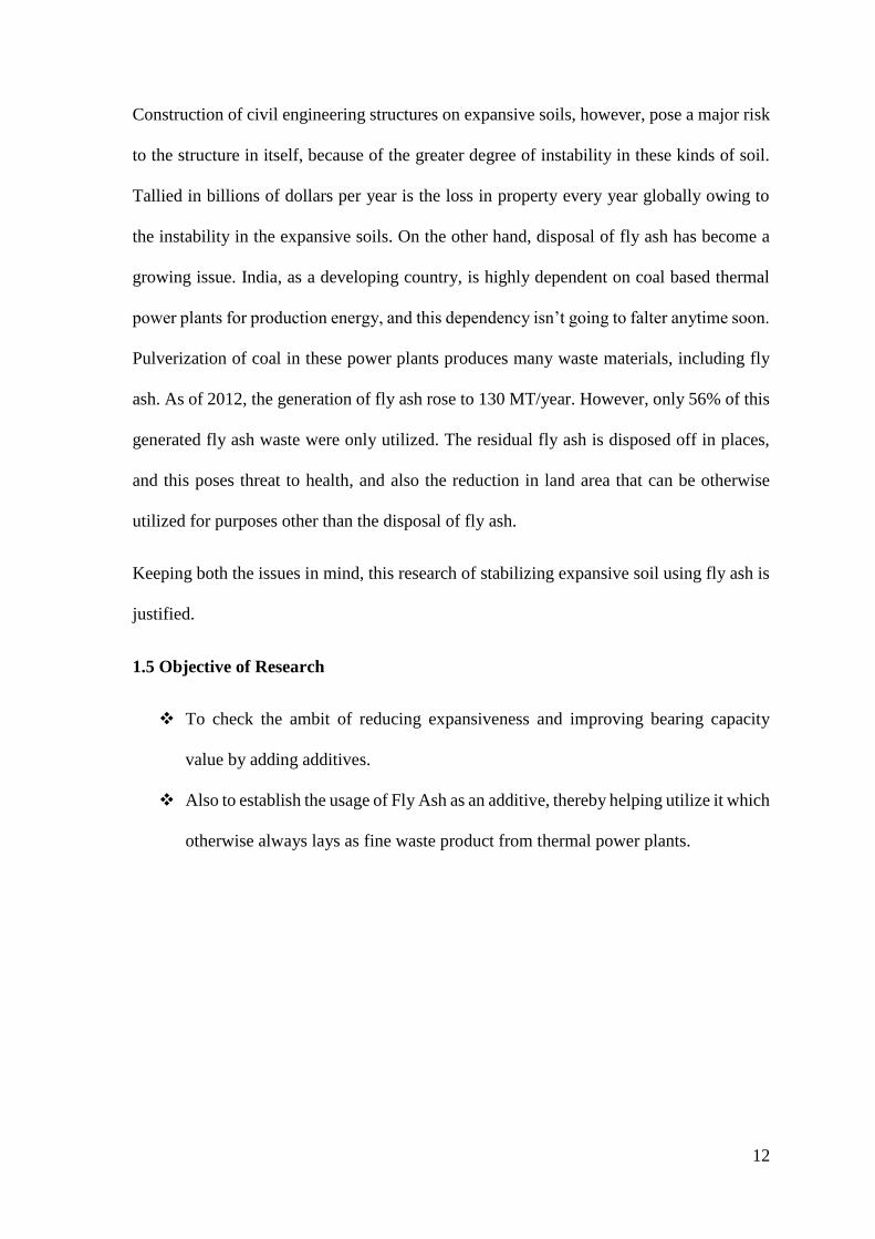
Also called as Black Cotton soils or Regur soils, expansive soils in the Indian subcontinent are
mainly found over the Deccan trap (Deccan lava tract), which includes Maharashtra, Andhra
Pradesh, Gujarat, Madhya Pradesh, and some scattered places in Odisha. These soils are also
found in the river valley of Narmada, Tapi, Godavari and Krishna. The depth of black cotton
soil is very large in the upper parts of Godavari and Krishna, and the north-western part of
Deccan Plateau. Basically, after the chemical decomposition of rocks such as basalt by various
decomposing agents, these are the residual soils left behind at the place of such an event.
Cooling of volcanic eruption (lava) and weathering another kind of rock – igneous rocks – are
also processes of formation of these type of soils. Rich in lime, alumina, magnesia, and iron,
these soils lack in nitrogen, phosphorus and organic content.
3
Consisting of high percentage of clay sized particles, the colour of this soil varies from black
to chestnut brown. 20% of the total land area, on an average, of this country is roofed by
expansive soils. These soils are suitable for dry farming and for the growth of crops like cotton,
rice, jowar, wheat, cereal, tobacco, sugarcane, oilseeds, citrus fruits and vegetables; the reason
behind it is owed to the moisture retentive capacity of expansive soils, which is high.
In the semi-arid regions, just in the last couple of decades, damages due to the swelling-
shrinking action of expansive soils have been observed prominently in form of cracking and
break-up of roadways, channel and reservoir linings, pavements, building foundations, water
lines, irrigation systems, sewer lines, and slab-on-grade members.

4
Figure 1 Major Soil Types in India
1.2 Fly Ash
A waste material extracted from the gases emanating from coal fired furnaces, generally of a
thermal power plant, is called fly ash. One of the chief usages of volcanic ashes in the ancient
ages were the use of it as hydraulic cements, and fly ash bears close resemblance to these
5
volcanic ashes. These ashes were believed to be one of the best pozzolans (binding agent) used
in and around the globe.
The demand of power supply has exponentially heightened these days due to increasing
urbanization and industrialization phenomena. Subsequently, this growth has resulted in the
increase in number of power supplying thermal power plants that use coal as a burning fuel to
produce electricity. The mineral residue that is left behind after the burning of coal is the fly
ash. The Electro Static Precipitator (ESP) of the power plants collect these fly ashes.
Production of fly ash comes with two major concerns – safe disposal and management of fly
ash. Because of the possession of complex characteristics of wasters which are generated from
the industries, and their hazardous nature, these wastes pose a necessity of being disposed in a
safe and effective way, so as to not disturb the ecological system, and not causing any sort of
catastrophe to human life and nature. Environmental pollution is imminent unless these
industrial wastes are pre-treated before their disposal or storage.
Essentially consisting of alumina, silica and iron, fly ashes are micro-sized particles. Fly ash
particles are generally spherical in size, and this property makes it easy for them to blend and
flow, to make a suitable concoction. Both amorphous and crystalline nature of minerals are the
content of fly ash generated. Its content varies with the change in nature of the coal used for
the burning process, but it basically is a non-plastic silt. For waste liners, fly ash is a potential
material that can be employed; and in combination with certain minerals (lime and bentonite),
fly ash can be used as a barrier material. In present scenario, the generation of this waste
material in picture (fly ash) is far more than its current utilization. In other words, we are
producing more of fly ash than we can spend.
6
1.2.1 Generation and Disposal
Usage of coal in thermal power plants for the generation of steam is a common practice. A
method that was proved to be non-energy efficient was used in the past, where coal in form of
lumps were expended in the furnaces of the boilers to generate the evaporated content: steam.
Thus, in order to optimize the production of energy from coal mass, the thermal power plants
began to use pulverized coal mass instead of the aforementioned content. In this process, firstly,
this pulverized coal is infused into the combustion chamber, where the instant but efficient
burning of fuel happens. The ash formed as a result of this is called the fly ash, and this fly ash
contains molten minerals. The steam around this molten mass, when the coal ash travels with
the flue gases, results in the spherical shape of the fly ash particle. Next, the employment of
the economizer recovers the heat from the steam gases and fly ash. As a result of this process,
the temperature of the fly ash shows a sudden reduction in value. If this temperature fall is
rapid, then the resulting structure of the fly ash material is amorphous. However, if the
temperature drop during this cooling process is gradual, then the fly ash assumes a more
crystalline in nature. This shows the implementation of the economizer, and how it improves
the reactivity process.
In the process where fly ash is not subjected to the economizer, it forms a 4.3% soluble matter,
and its pozzolanic activity index clocks to 94%. Whereas, during the process where the fly ash
exposed to the economizer, its pozzolanic activity clocks to 103% and it forms a 8.8% soluble
matter. In conclusion, fly ashes are separated from the flue gases by a mechanical dust collector,
which is commonly referred to as Electro Static Precipitator (ESP), or scrubbers. Free of fly
ashes, the rest of the flue gases are liberated into the atmosphere via the chimney.
With about 90%-98%, the efficiency of ESPs for the separation of finer and lighter fly ash
particles is high. In general, the fly ash consists of four to six hoppers, named as field. The
7
fineness of the fly ash particles collected are thus proportional to the number of fields available
in an ESP. Therefore, the fly ashes that are collected from the first hopper have a specific
surface area of about 2800 𝑐𝑚2/gm, whereas the fly ash collected from the last hopper exhibit
a greater specific surface area, that is, 8200 𝑐𝑚2/gm. With the scorching of pulverized coal,
the resulting ash content forming during the process are either collected as fly ash or bottom
ash. 80% of coal ashes that are removed from the flue gases are recovered as fly ash, whereas
the remaining 20%, that are generally coarser in size, are collected at the bottom of the furnace
as bottom ash. Either in dry form, or its collection from a water-filled hopper, bottom ash is
taken from the bottom of the furnace. When there is a sufficient amount of bottom ash in the
water-filled hopper, beyond which its disposal becomes imminent before moving on to the next
process, the transference can occur by water jets or water sluice to a disposal pond which. This
disposed waste is then called as pond ash. The below figure gives an idea of disposal of coal
ash in a thermal power plant where coal is a fuel.
1.2.2 Classification of fly ash
The extracted ash from the flue gases via an Electro Static Precipitator, after the process of
pulverization, is called fly ash. It is the finest of particles among bottom ash, pond ash and fly
ash. With some unburned carbon, the fly ash chiefly consists of non-combustible particulate
matter. These generally consists of silt-sized particles. On the basis of a lime reactivity test, fly
ashes have been classified into four different types, as given:
Cementitious fly ash
Cementitious and pozzolanic fly ash
Pozzolanic fly ash
Non-pozzolanic fly ash
8
With free lime content and negligible reactive silica, this fly ash is called as cementitious. As
opposed to this, with negligible free lime content, and chiefly reactive silica, this fly ash is
called pozzolanic fly ash. Both reactive silica and free lime are predominant in cementitious
and pozzolanic fly ash. Neither free lime, nor reactive silica are present in non-pozzolanic fly
ash. The distinguishable difference between cementitious fly ash and pozzolanic fly ash is that
the cementitious fly ash hardens when it comes in connexion with water, whereas the
pozzolanic fly ash hardens only after the activated lime reacts with water. Cementitious &
Pozzolanic Fly Ash and Pozzolanic Fly Ash are the types that are found widely.
Based on the chemical composition of fly ash, fly ash has been categorized into two categories,
as given:
Class C fly ash
Class F fly ash
Burning of sub-bituminous type of coal and lignite, which contains more than 20% Calcium
Oxide, gives the Class C fly ash. By ignition of anthracite and bituminous type of coal, Class
F fly ash comes into the picture. This fly ash contains less than 20% Calcium Oxide.
9
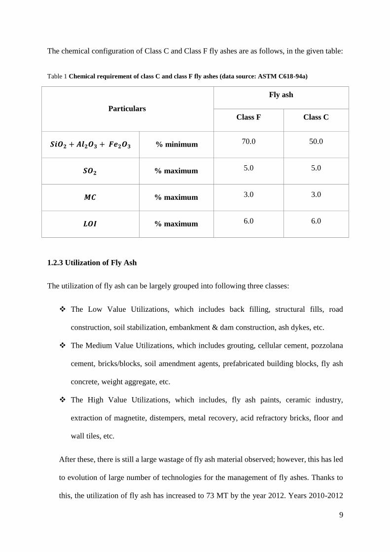
The chemical configuration of Class C and Class F fly ashes are as follows, in the given table:
Table 1 Chemical requirement of class C and class F fly ashes (data source: ASTM C618-94a)
Particulars
Fly ash
Class F Class C
𝑺𝒊𝑶𝟐 + 𝑨𝒍𝟐𝑶𝟑 + 𝑭𝒆𝟐𝑶𝟑 % minimum 70.0 50.0
𝑺𝑶𝟐 % maximum 5.0 5.0
𝑴𝑪 % maximum 3.0 3.0
𝑳𝑶𝑰 % maximum 6.0 6.0
1.2.3 Utilization of Fly Ash
The utilization of fly ash can be largely grouped into following three classes:
The Low Value Utilizations, which includes back filling, structural fills, road
construction, soil stabilization, embankment & dam construction, ash dykes, etc.
The Medium Value Utilizations, which includes grouting, cellular cement, pozzolana
cement, bricks/blocks, soil amendment agents, prefabricated building blocks, fly ash
concrete, weight aggregate, etc.
The High Value Utilizations, which includes, fly ash paints, ceramic industry,
extraction of magnetite, distempers, metal recovery, acid refractory bricks, floor and
wall tiles, etc.
After these, there is still a large wastage of fly ash material observed; however, this has led
to evolution of large number of technologies for the management of fly ashes. Thanks to
this, the utilization of fly ash has increased to 73 MT by the year 2012. Years 2010-2012

10
saw a wide acceptance of fly ash as a product that can be used in various purposes.
Presently, the production of fly ashes in India is about 130 MT/year, and this is expected
to rise by 400 MT by the year 2016-2017, as stated by 2nd annual international summit for
fly ash utilization 2012, scheduled on 17th-18th of January, 2013 at NDCC II convention
centre, NDMC Complex, New Delhi, India.
Table 2 Production & Utilization of fly ashes in different countries
Ref: Alam and Akhtar, International Journal of emerging trends in engineering and development,
Vol.1 [2] (2011)
Country Annual Ash Production
(MT) Ash Utilization in %
India 131 56
China 100 45
Germany 40 85
Australia 10 85
France 3 85
Italy 2 100
USA 75 65
UK 15 50
Canada 6 75
Denmark 2 100
Netherland 2 100
As a palpable conclusion from the previous table, the fly ash utilization in India is about
56%, as in 2010-2012, which leads to the fact that the rest 44% are waste material,
dumped/disposed chiefly out in the open, and considering the adverse effect of this waste
material on our environment, it is of necessity to utilize all of the fly ash produced by coal
based thermal power plants. An increase of efforts have to be observed if we were to
achieve a 100% utilization of this waste product. If we were to execute the usage of fly ash

11
properly in low value applications, more than 60% utilization of fly ash we currently
produce can be seen. In present scenario, India is 65%-70% dependent on production of
energy by coal based thermal power plants, which tallies the fly ash production of the
country, as stated earlier, up to 130 MT/year.
Table 3 Utilization of fly ash for different purposes. Data source: Ministry of Environment & Forests
Mode of Fly ash applications % Utilization
Dykes 35
Cement 30
Land development 15
Building 15
Others 5
1.3 Reaction mechanism of Fly ash and expansive soil
By itself, fly ash has little cementitious value, however, this changes in presence of
moisture, with which it reacts chemically, and forms cementitious compounds. These
compounds attributes to the improvement of compressibility and strength characteristics of
a soil. Both classes of Fly ash (C & F) are pozzolans i.e. they contain siliceous and
aluminous materials. Fly ash can thus produce an assortment of divalent and trivalent
cations (𝐶𝑎2+, 𝐹𝑒3+, 𝐴𝑙3+ etc.) under conditions that are ionized in nature, which in return
can encourage flocculation of dispersed clay particles. Expansive soils can thus be
theoretically stabilized in an effective manner by cationic exchange with fly ash.
1.4 Justification of research
Almost 20% of land in India is roofed by expansive soils. With the rapid growth in
industrialization and urbanization, land scarcity appears to be an imminent threat.
12
Construction of civil engineering structures on expansive soils, however, pose a major risk
to the structure in itself, because of the greater degree of instability in these kinds of soil.
Tallied in billions of dollars per year is the loss in property every year globally owing to
the instability in the expansive soils. On the other hand, disposal of fly ash has become a
growing issue. India, as a developing country, is highly dependent on coal based thermal
power plants for production energy, and this dependency isn’t going to falter anytime soon.
Pulverization of coal in these power plants produces many waste materials, including fly
ash. As of 2012, the generation of fly ash rose to 130 MT/year. However, only 56% of this
generated fly ash waste were only utilized. The residual fly ash is disposed off in places,
and this poses threat to health, and also the reduction in land area that can be otherwise
utilized for purposes other than the disposal of fly ash.
Keeping both the issues in mind, this research of stabilizing expansive soil using fly ash is
justified.
1.5 Objective of Research
To check the ambit of reducing expansiveness and improving bearing capacity
value by adding additives.
Also to establish the usage of Fly Ash as an additive, thereby helping utilize it which
otherwise always lays as fine waste product from thermal power plants.

13
Chapter 2
LITERATURE REVIEW
14
2.1 Origin and occurrence of expansive soil
Clay mineral is the key element which divulges the swelling characteristics to any ordinary
non-swelling/non-shrinking soil. Montmorillonite, out of several types of clay minerals has the
maximum amount of swelling potential. In-situ formation of chief clay minerals occurs under
alkaline conditions, or sub-aqueous decomposition of blast rocks can be seen the origin of such
soil – expansive soil. These type of soil can also be formed due to weathering under alkaline
environments, and under adequate supply of magnesium or ferric or ferrous oxides. Given
there’s a good availability of alumina and silica, the formation of Montmorillonite is favoured.
2.2 Nature of expansive soil
Swelling in clays can be sub-categorized into two distinctive types, namely:
Elastic rebound in the compressed soil mass due to reduction in compressive force.
Imbibing of water resulting in expansion of water-sensitive clays.
Swelling clays are the clays that exhibit latter type of swelling, where the clay minerals with
largely inflating lattice are present. One of the fundamental characteristics of clayey soil is that
they display little cohesion and strength when wet, but they become hard when devoid of water.
However, all of them do not swell due to wetting action. Decrease in ultimate bearing capacity
at saturation, and large differential settlement due to this occurs. Thus, clayey soils exhibit
foundation problems.
15
2.3 Clay Mineralogy
On the basis of their crystalline arrangement, clay minerals can be categorized into three
general groups, namely:
Kaolinite group
Montmorillonite group
Illite group
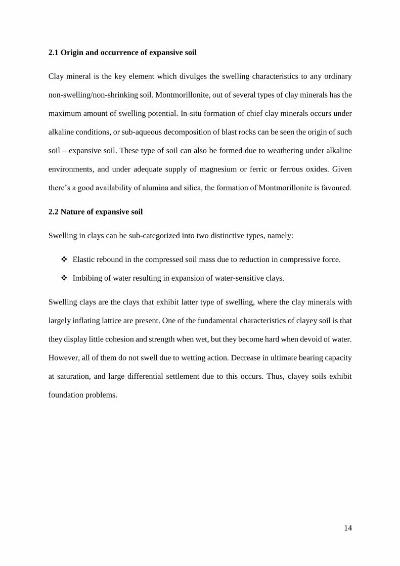
2.3.1 Kaolinite group
A clay mineral which has a chemical composition 𝐴𝑙2𝑆𝑖205(𝑂𝐻)4 is called Kaolinite. This
type of clay mineral has a layered silicate, with linkage to one octahedral sheet of alumina
through oxygen atoms. China clay or Kaolin is the name given to rocks that are rich in this
mineral. A thickness of 7Å is exhibited by the stacked layers of kaolinite; as a result of this,
kaolin group of minerals are seen to be the most stable, which is also because of the fact that
water cannot enter between the sheets to inflate that unit cell.
Figure 2 Atomic structure of kaolinite
16
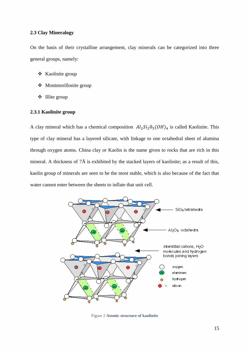
2.3.2 Montmorillonite group
Two silica tetrahedral sheets combined with a central alumina octahedral sheet comprise the
structural arrangement of Montmorillonite. The bond between crystal links is weak here. Thus,
the soil containing higher percentage of Montmorillonite minerals demonstrate high shrinkage
and swelling characteristics, depending on the nature of exchangeable cation present. The
common layer of a Montmorillonite unit is formed by one of the hydroxyl layers of the
octahedral sheet and the tips of the tetrahedrons from each silica sheet. Atoms which are
common to both silica and gibbsite layers never participate in the process of swelling. During
weak bond between the crystal forms, water can penetrate, breaking the structures to 10Å
structural units.
Figure 3 Atomic structure of montmorillonite
17
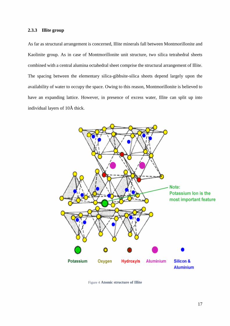
2.3.3 Illite group
As far as structural arrangement is concerned, Illite minerals fall between Montmorillonite and
Kaolinite group. As in case of Montmorillonite unit structure, two silica tetrahedral sheets
combined with a central alumina octahedral sheet comprise the structural arrangement of Illite.
The spacing between the elementary silica-gibbsite-silica sheets depend largely upon the
availability of water to occupy the space. Owing to this reason, Montmorillonite is believed to
have an expanding lattice. However, in presence of excess water, Illite can split up into
individual layers of 10Å thick.
Figure 4 Atomic structure of Illite
18
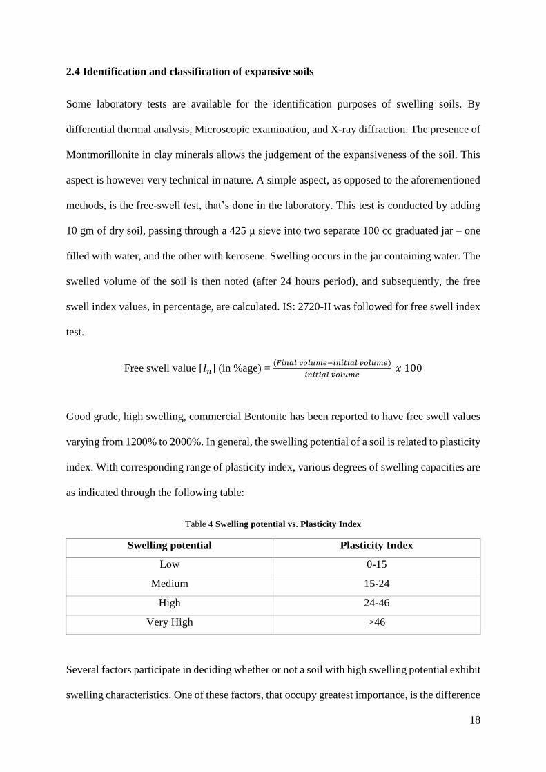
2.4 Identification and classification of expansive soils
Some laboratory tests are available for the identification purposes of swelling soils. By
differential thermal analysis, Microscopic examination, and X-ray diffraction. The presence of
Montmorillonite in clay minerals allows the judgement of the expansiveness of the soil. This
aspect is however very technical in nature. A simple aspect, as opposed to the aforementioned
methods, is the free-swell test, that’s done in the laboratory. This test is conducted by adding
10 gm of dry soil, passing through a 425 μ sieve into two separate 100 cc graduated jar – one
filled with water, and the other with kerosene. Swelling occurs in the jar containing water. The
swelled volume of the soil is then noted (after 24 hours period), and subsequently, the free
swell index values, in percentage, are calculated. IS: 2720-II was followed for free swell index
test.
Free swell value [𝐼𝑛] (in %age) = (𝐹𝑖𝑛𝑎𝑙 𝑣𝑜𝑙𝑢𝑚𝑒−𝑖𝑛𝑖𝑡𝑖𝑎𝑙 𝑣𝑜𝑙𝑢𝑚𝑒)
𝑖𝑛𝑖𝑡𝑖𝑎𝑙 𝑣𝑜𝑙𝑢𝑚𝑒 𝑥 100
Good grade, high swelling, commercial Bentonite has been reported to have free swell values
varying from 1200% to 2000%. In general, the swelling potential of a soil is related to plasticity
index. With corresponding range of plasticity index, various degrees of swelling capacities are
as indicated through the following table:
Table 4 Swelling potential vs. Plasticity Index
Swelling potential Plasticity Index
Low 0-15
Medium 15-24
High 24-46
Very High >46
Several factors participate in deciding whether or not a soil with high swelling potential exhibit
swelling characteristics. One of these factors, that occupy greatest importance, is the difference
19
between soil moisture content at the time of construction, and final (equilibrium) moisture
content finally achieved under various conditions allied with the complicated structure. The
soil has a high swelling capacity if the equilibrium moisture content is higher than the soil
moisture content. Large swelling pressure may develop as a result of the upheaving of the soil
or structure, causing swelling.
2.5 Methods of recognizing expansive soils
Grouped into three categories, following are the methods of recognizing expansive soils:
Mineralogical identification
Indirect methods, such as soil suction, activity and index properties
Direct measurement.
Impractical and uneconomical in practice, methods of mineralogical identification still hold
importance in exploring basic properties of clay minerals. Direct measurement, out of the
remaining two categories, offers the most useful data.
By their shattered or fissured condition, or obvious structural damage to existing buildings
caused by such soils, potentially expansive soils are usually identified in the field. To classify
expansive soil, potential swell, or potential expansion, or the degree of expansion is a favoured
term used; from this, geotechnical engineers establish how good or bad the expansive soils are.
2.6 Causes of swelling
There are different theories, but the mechanism of swelling is still unclear. No conclusion to
the mechanism have been reached. Soil consisting high percentage of clay or colloid, with
Montmorillonite mineral present as the chief mineral is one of the most universally accepted
reasons for the swelling of soils.
20
2.7 Swell Pressures
The pressure exerted by expansive soil when they swell, owing to their contact with water, is
called swell pressure. The estimation of this swell pressure and likely becomes a very important
task for designing a structure on such soils, or building the core of a dam, or constructing a
road embankment, or taking a canal through such soils.
2.8 Factors affecting swelling
Initial moisture content, or the molding water in case of a re-molded sample is the most
influencing factor. “The behaviour of re-molded clays is much as undisturbed clays”, as per
Holts’ and Gibbs’ findings. For a given dry density, the value of initial water content will be a
key factor in determining the water affinity of a given sample, as well as its swell pressure. A
minimum moisture content (𝑤𝑛) required by a clay for swelling to begin beneath a pre-paved
sub-grade is given by:
Where, 𝑤1 = liquid limit
The factors that affect the swelling aspect of a soil largely depend on the soil’s environmental
conditions. With the intake of water, swelling is more in a soil element which is close to the
surface, but if below the surface, the same soil exhibit negligible swelling because the
overburden pressure neutralizes the developing swelling pressure of the dry soil.
Generally responsible for swelling are the following factors:
Location of the soil sample from the ground surface
Thickness, as well as shape of the sample
Change in volume
Temperature
𝑤𝑛(%) = 0.2𝑤1 + g
21
Nature of pore fluid
Time
Stress history
Unit weight of the sample taken, etc.
2.9 Problems associated with the expansive soil
Generation of problems for all kinds of construction over expansive soils is common, leading
us to believe that such types of soil are not suitable for these purposes. However, given the
placement of these kinds of soil over the country, it leaves engineers no other choice but to
develop different structures on the soil, well aware of the risk. These structures chiefly are a
part of irrigation projects. Buildings, and other kinds of structures constructed over these soils
are subjected to differential deflections. These deflections cause distressing, and in turn leads
to damage of the structure.
Moreover, the reduction in moisture content due to the evaporation of water in soil causes
shrinkage, and heaving of soil occurs when there is a disproportionate increase in moisture
content. The level of ground water table also has a significant impact on the moisture content
of these soils, which in return affect the shrinkage-swelling cycles. In seasons which are dry in
nature, the surface of clayey soil shrinks, however, little evaporation is there on the clayey soil
on which the building stands. This causes differential settlement at plinth level, posing danger
to the structure.
If the construction of a building on such type of soil is done in its dry season, the base of the
structure’s foundation would experience swelling pressures when the partially saturated soil
underneath starts imbibing water in the wet season, developing swelling pressures. When the
pressure imposed by the structure on the foundation is less than the swelling pressure
developed, upliftment of such a structure occurs, which would lead to formation of cracks. The
22
imposed bearing pressure if the building is constructed in the wet season should be within the
permissible limits of bearing pressure for the soil. A better practice is to construct a building
during dry season, and completing it before the onset of wet seasons.
One of the methods of treatment of expansive soil to make them fit for the construction
purposes is called stabilization. According to Petry (2002), assortment of stabilizers can be
grouped into:
By-product stabilizers (Quarry dust, Fly ash, Slag, Phosphor-gypsum, etc.)
Traditional stabilizers (Cement, Lime, etc.)
Non-traditional stabilizers (Sulfonated oils, Potassium compounds, Polymer, Enzymes,
etc.)
Lots of geo-environmental problems are a result of industrial by-products whose disposal as
fills in disposal sites adjacent to the industries demand large chunks of land, which can
otherwise be utilized for construction, growing of vegetation, etc. purposes. Various attempts
by different researchers and organizations have been made to utilize these by-products.
Stabilization of expansive soil is one of the ways of fulfilling such a thing.
2.10 Stabilization using fly ash
Sharma et al. (1992), using mixtures of fly ash, blast furnace slag and gypsum, studied
stabilization. He found that when fly ash, gypsum and blast furnace slag are used in proportions
of 6:12:18, the swelling pressure decreases from 248 KN/𝑚2 to 17 KN/𝑚2, whereas an increase
by 300% was observed in case of unconfined compressive strength.
Srivastava et al. (1997) studied the microscopic changes in the fabric and micro-structure of
the expansive soil due to the addition of lime sludge and fly ash using SEM photography. He
found that there were changes in the micro-structure and fabric of the expansive soil when 16%
lime sludge and 16% fly ash were both added. Srivastava et al. (1999) have also stated that the
23
best stabilizing effect of the swelling and consolidation behaviour in an expansive soil mixed
with fly ash and lime sludge was obtained when 16% lime sludge and 16% fly ash were added.
Cokca (2001) found out that swelling pressure decreased by 75% after 7 day curing, and 79%
after 28 day curing when soil specimens were treated with 25% Class C Fly ash (18.98% of
CaO).
Pandian et al. (2001) made an effort towards stabilization of expansive soil by using Class F
Fly ash. He found that fly ash can make for an effective additive when he saw that with 20%
fly ash content, the CBR value of Black cotton soil improved (about 200%) significantly.
Turker et al. (2004) employed sand along with Class C & Class F fly ash for stabilization of
expansive soil. Without any contradiction of belief, Class C fly ash was more effective in
stabilization, and decrease in free swell with curing period was observed. The percentage
content of soil, Class C fly ash and sand that gave the best result was 75%, 15% and 10%
respectively.
Satyanarayana et al. (2004) aimed to study the mutual effect of addition of lime and fly ash on
the engineering properties of the expansive soil. He found out that 70%, 26% and 4% were the
optimum percent mixture of the ingredients for the construction of roads and embankments.
Phani Kumar et al. (2004) saw that the hydraulic conductivity, swelling properties and
plasticity of expansive soil-fly ash mixture decreased, whereas the strength and dry unit weight
increased with the increase of fly ash content in the mix. For a given water content, the
resistance to penetration also increased with the increase in fly ash content.
Baytar (2005) contemplated the stabilization of expansive soils using desulphogypsum and fly
ash acquired from a thermal power plant by 0 to 30%. A variable percentage of lime (0 to 8%)
was appended into the expansive soil-desulphogypsum-fly ash mixture. The samples, thus
formed, were cure for a period of 7 days and 28 days. It was observed that swelling percentage

24
decrease, and there was an increase in rate of swell with increasing percentage of the stabilizer
in the mixture. The curing process reduced the swelling percentage further; and with the
addition of 30% desulphogypsum and 25% fly ash, reduction in swelling percentage were to
such levels that stood comparable with the one where lime was only used as stabilizing
compound for the expansive soil.
Amu et al. utilized fly ash and cement mixture for the stabilization purposes of expansive soil.
Three distinct classes of samples: (i) 12% cement, (ii) 9% cement + 3% fly ash, and (iii) natural
clay soil, were taken to be tested for Maximum Dry Densities (MDD), Unconfined
Compressive Strength (UCS), Optimum Moisture Contents (OMC), California Bearing Ratios
(CBR), and the Undrained Triaxial tests. The results of this test indicated that the sample with
9% cement and 3% fly ash showed better results with respect to CBR, OMC, MDD, and
shearing resistance, in comparison to the other two samples. This indicated the value of fly ash
as a stabilizing agent.
Sabat et al. (2005) studied the stabilization of expansive soil using fly ash-marble powder
mixture. He concluded that the optimum proportions of soil, fly ash, and marble powder in the
mixture in percentage by weight to give the best result were 65%, 20% and 15% respectively.
Rajesh et al. (2006) talked about experimental investigation of clay beds stabilized with fly
ash-lime segments and fly ash segments. An observation of swelling in clay beds of 100 mm
thickness strengthened with 30 mm diameter fly ash-lime and fly ash segments. There was a
considerable decrease in heave in both fly ash-lime and fly ash columns. However, lime-fly
ash mixture generated better results.
Wagh (2006) utilized rock flour, lime and fly ash independently, furthermore in diverse extent
to stabilize the black cotton soil from Nagpur Plateau, India. Rock flour or fly ash, or both
together, when added to the black cotton soil showed an improved value of CBR to some
25
degree, and there was an increase in angle of shearing resistance with the reduction in cohesion
value. CBR values increased significantly with the increase of both frictional resistance and
cohesion where lime, in addition to both fly ash and rock flour, as added into the mixture.
Sharma et al. (2007) contemplated the impact on swelling of highly plastic expansive clay, and
the compressibility of another non-expansive but highly plastic clay when fly ash was
employed. At a given dry unit weight of the mixture, the swelling pressure and swell potential
showed a decrease by nearly 50%. A decrease by 40% at 20% fly ash content in coefficient of
secondary consolidation and compression index of both the samples was observed.
Buhler et al. (2007) considered the usage of lime and Class C fly ash in stabilization of
expansive soils. He observed better results with lime than with Class C fly ash, when the
reduction in linear shrinkage was better when the former was employed. This, however,
established the characteristics of fly ash as a stabilizing material.

26
Chapter 3
MATERIALS AND
METHODOLOGY
27
3.1 Materials
3.1.1 Expansive soil
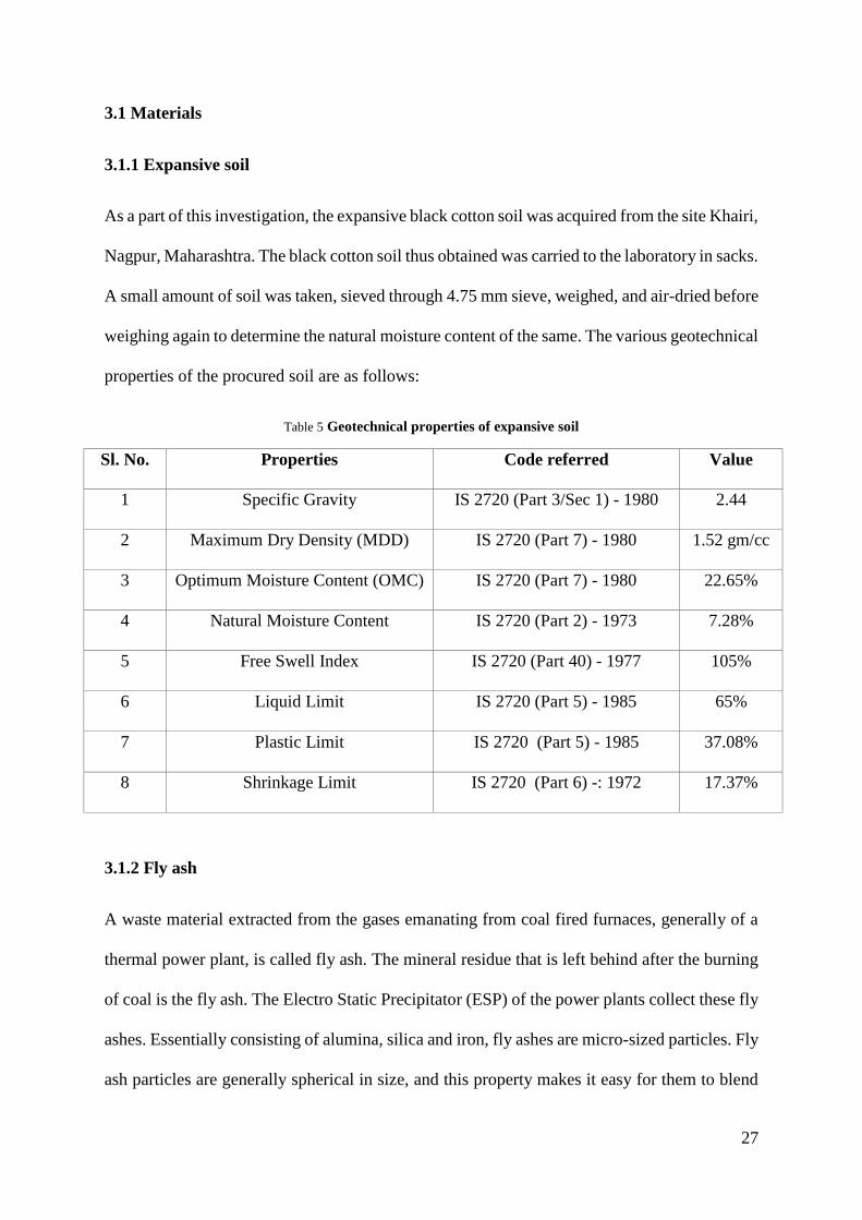
As a part of this investigation, the expansive black cotton soil was acquired from the site Khairi,
Nagpur, Maharashtra. The black cotton soil thus obtained was carried to the laboratory in sacks.
A small amount of soil was taken, sieved through 4.75 mm sieve, weighed, and air-dried before
weighing again to determine the natural moisture content of the same. The various geotechnical
properties of the procured soil are as follows:
Table 5 Geotechnical properties of expansive soil
Sl. No. Properties Code referred Value
1 Specific Gravity IS 2720 (Part 3/Sec 1) - 1980 2.44
2 Maximum Dry Density (MDD) IS 2720 (Part 7) - 1980 1.52 gm/cc
3 Optimum Moisture Content (OMC) IS 2720 (Part 7) - 1980 22.65%
4 Natural Moisture Content IS 2720 (Part 2) - 1973 7.28%
5 Free Swell Index IS 2720 (Part 40) - 1977 105%
6 Liquid Limit IS 2720 (Part 5) - 1985 65%
7 Plastic Limit IS 2720 (Part 5) - 1985 37.08%
8 Shrinkage Limit IS 2720 (Part 6) -: 1972 17.37%
3.1.2 Fly ash
A waste material extracted from the gases emanating from coal fired furnaces, generally of a
thermal power plant, is called fly ash. The mineral residue that is left behind after the burning
of coal is the fly ash. The Electro Static Precipitator (ESP) of the power plants collect these fly
ashes. Essentially consisting of alumina, silica and iron, fly ashes are micro-sized particles. Fly
ash particles are generally spherical in size, and this property makes it easy for them to blend

28
and flow, to make a suitable concoction. Both amorphous and crystalline nature of minerals
are the content of fly ash generated. Its content varies with the change in nature of the coal used
for the burning process, but it basically is a non-plastic silt. For the purpose of investigations
in this study, fly ash was obtained from Sesa Sterlite, Jharsuguda, Odisha. To separate out the
vegetation and foreign material, this fly ash was screen through a 2 mm sieve. The samples
were dried in the oven for about 24 hours before further usage.
3.2 Methodology Adopted
To evaluate the effect of fly ash as a stabilizing additive in expansive soils, series of tests,
where the content of fly ash in the expansive soil was varied in values of 10% to 50% (multiples
of 10) by weight of the total quantity taken. The Indian Standard codes were followed during
the conduction of the following experiments:
o Standard proctor test – IS : 2720 (Part 7) - 1980
o Unconfined compressive strength (UCS) test – IS : 2720 (Part 10) - 1991
o California bearing ratio (CBR) test – IS : 2720 (Part 16) - 1987
o Free swell index test – IS 2720 (Part 40) - 1977
o Liquid & Plastic limit test – IS 2720 (Part 5) - 1985

29
Chapter 4
RESULTS AND
DISCUSSIONS

30
4.1 Standard proctor test for soil – fly ash mixture
Table 6 Standard proctor test for expansive soil only
Volume of
Mold (𝒎𝟑)
Weight of
soil in mold
(kg)
Moist unit
weight
(g/𝐜𝒎𝟑)
Moisture
content (%)
Dry unit
weight
(g/𝐜𝒎𝟑)
ZAV
(g/𝐜𝒎𝟑)
0.00099795 1.56 1.56 17.76 1.32 1.70
0.00099795 1.73 1.73 19.53 1.45 1.65
0.00099795 1.86 1.86 22.65 1.52 1.57
0.00099795 1.87 1.87 24.87 1.50 1.52
0.00099795 1.82 1.82 27.92 1.42 1.45
Table 7 Standard proctor test for expansive soil + 10% fly ash mixture
Volume of
Mold (𝒎𝟑)
Weight of
soil in mold
(kg)
Moist unit
weight
(g/𝐜𝒎𝟑)
Moisture
content (%)
Dry unit
weight
(g/𝐜𝒎𝟑)
ZAV
(g/𝐜𝒎𝟑)
0.00099795 1.60 1.60 15.18 1.39 1.78
0.00099795 1.76 1.76 19.09 1.48 1.66
0.00099795 1.83 1.83 22.13 1.50 1.58
0.00099795 1.80 1.81 27.96 1.41 1.45
0.00099795 1.77 1.77 32.71 1.33 1.35
Table 8 Standard proctor test for expansive soil + 20% fly ash mixture
Volume of
Mold (𝒎𝟑)
Weight of
soil in mold
(kg)
Moist unit
weight
(g/𝐜𝒎𝟑)
Moisture
content (%)
Dry unit
weight
(g/𝐜𝒎𝟑)
ZAV
(g/𝐜𝒎𝟑)
0.00099795 1.62 1.62 19.6 1.36 1.65
0.00099795 1.72 1.72 20.95 1.42 1.61
0.00099795 1.86 1.86 22.56 1.52 1.57
0.00099795 1.87 1.88 25.21 1.50 1.51
0.00099795 1.82 1.82 29.13 1.41 1.42
31
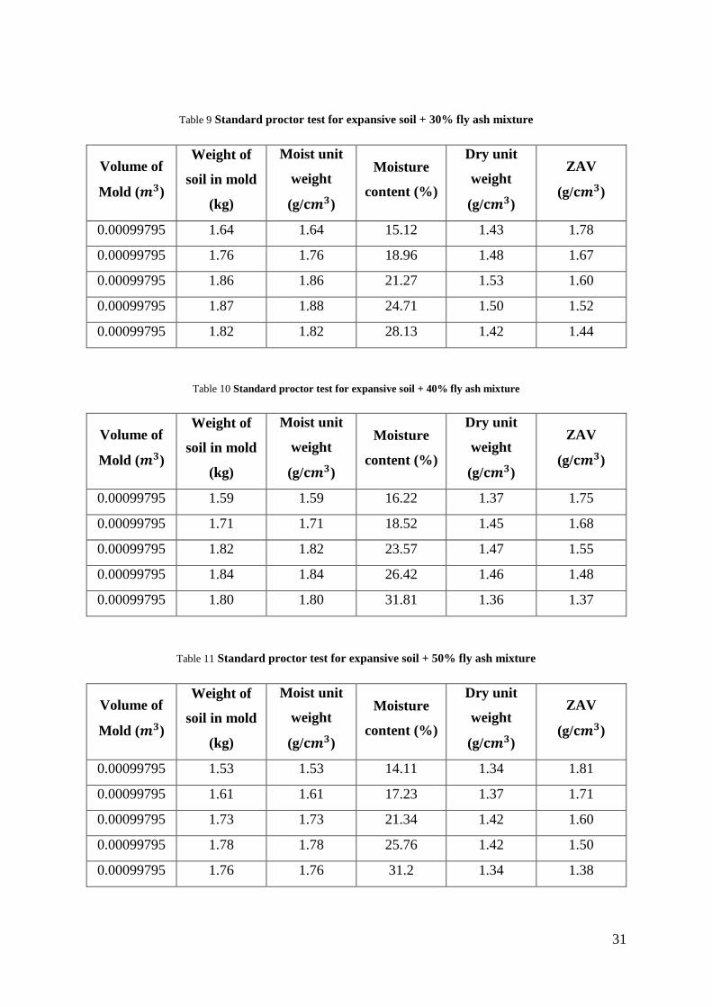
Table 9 Standard proctor test for expansive soil + 30% fly ash mixture
Volume of
Mold (𝒎𝟑)
Weight of
soil in mold
(kg)
Moist unit
weight
(g/𝐜𝒎𝟑)
Moisture
content (%)
Dry unit
weight
(g/𝐜𝒎𝟑)
ZAV
(g/𝐜𝒎𝟑)
0.00099795 1.64 1.64 15.12 1.43 1.78
0.00099795 1.76 1.76 18.96 1.48 1.67
0.00099795 1.86 1.86 21.27 1.53 1.60
0.00099795 1.87 1.88 24.71 1.50 1.52
0.00099795 1.82 1.82 28.13 1.42 1.44
Table 10 Standard proctor test for expansive soil + 40% fly ash mixture
Volume of
Mold (𝒎𝟑)
Weight of
soil in mold
(kg)
Moist unit
weight
(g/𝐜𝒎𝟑)
Moisture
content (%)
Dry unit
weight
(g/𝐜𝒎𝟑)
ZAV
(g/𝐜𝒎𝟑)
0.00099795 1.59 1.59 16.22 1.37 1.75
0.00099795 1.71 1.71 18.52 1.45 1.68
0.00099795 1.82 1.82 23.57 1.47 1.55
0.00099795 1.84 1.84 26.42 1.46 1.48
0.00099795 1.80 1.80 31.81 1.36 1.37
Table 11 Standard proctor test for expansive soil + 50% fly ash mixture
Volume of
Mold (𝒎𝟑)
Weight of
soil in mold
(kg)
Moist unit
weight
(g/𝐜𝒎𝟑)
Moisture
content (%)
Dry unit
weight
(g/𝐜𝒎𝟑)
ZAV
(g/𝐜𝒎𝟑)
0.00099795 1.53 1.53 14.11 1.34 1.81
0.00099795 1.61 1.61 17.23 1.37 1.71
0.00099795 1.73 1.73 21.34 1.42 1.60
0.00099795 1.78 1.78 25.76 1.42 1.50
0.00099795 1.76 1.76 31.2 1.34 1.38
32
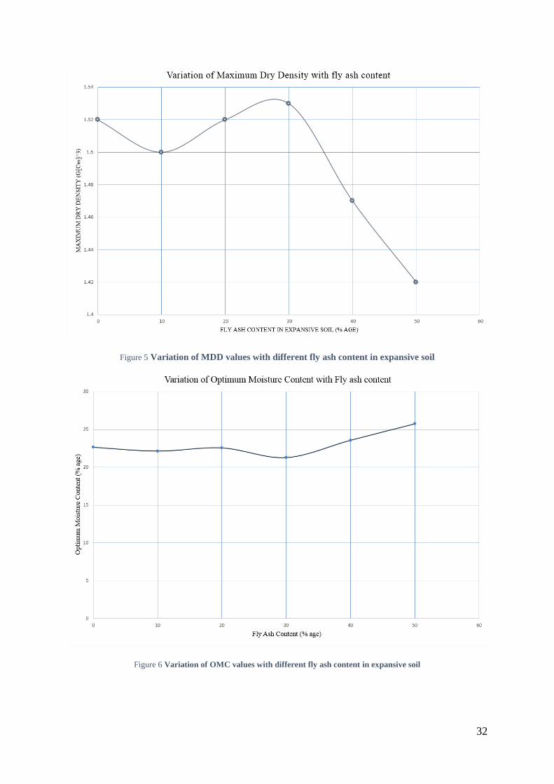
Figure 5 Variation of MDD values with different fly ash content in expansive soil
Figure 6 Variation of OMC values with different fly ash content in expansive soil

33
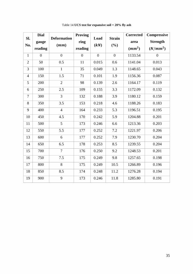
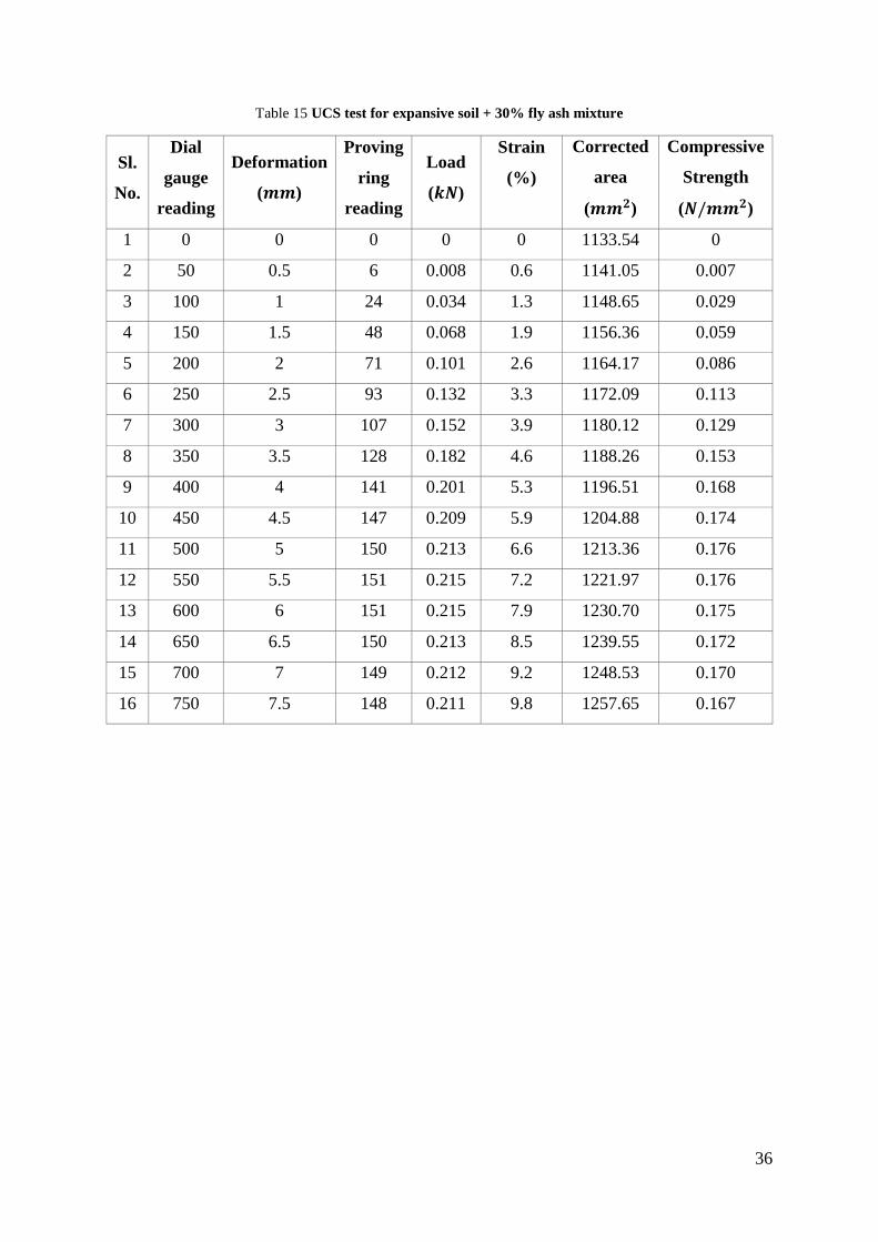
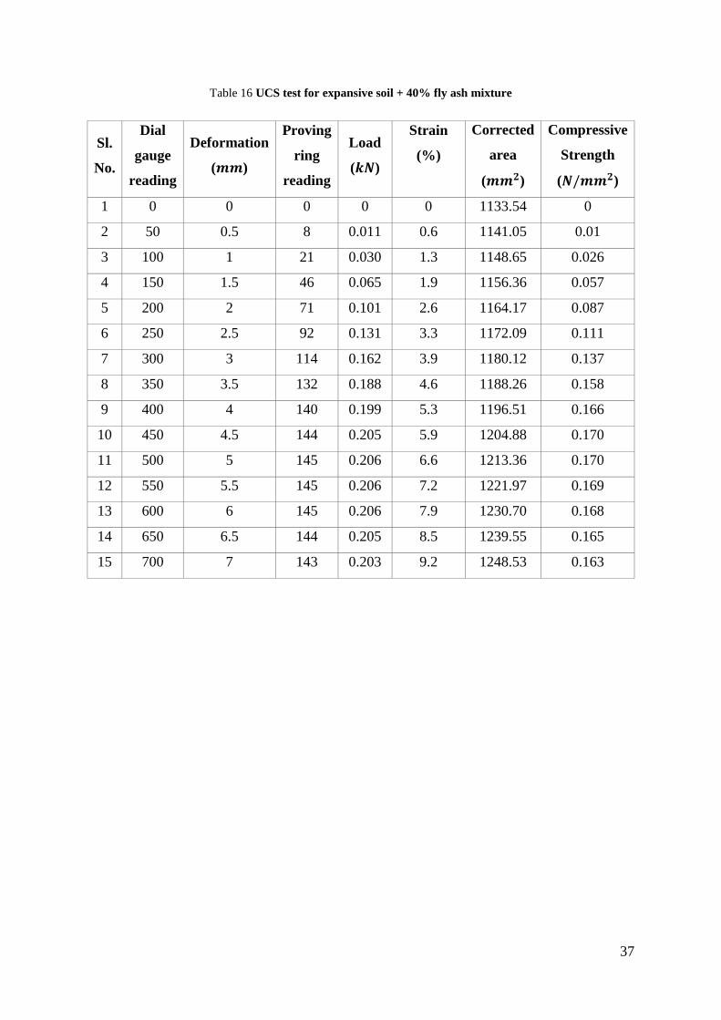
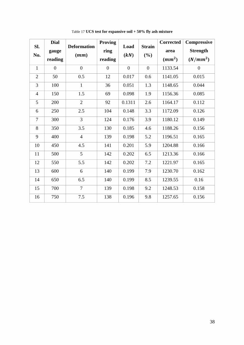
4.2 Unconfined Compressive Strength (UCS) test for soil – fly ash mixture
Table 12 UCS test for expansive soil only
Sl.
No.
Dial
gauge
reading
Deformation
(𝒎𝒎)
Proving
ring
reading
Load
(𝒌𝑵)
Strain
(%)
Corrected
area
(𝒎𝒎𝟐)
Compressive
Strength
(𝑵/𝒎𝒎𝟐)
1 0 0 0 0 0 1133.54 0
2 50 0.5 14 0.019 0.6 1141.04 0.017
3 100 1 36 0.052 1.3 1148.65 0.044
4 150 1.5 69 0.098 1.9 1156.36 0.085
5 200 2 101 0.144 2.6 1164.17 0.123
6 250 2.5 111 0.158 3.3 1172.09 0.135
7 300 3 131 0.186 3.9 1180.12 0.158
8 350 3.5 149 0.212 4.6 1188.26 0.178
9 400 4 159 0.226 5.3 1196.51 0.189
10 450 4.5 166 0.236 5.9 1204.88 0.196
11 500 5 168 0.240 6.6 1213.36 0.197
12 550 5.5 169 0.241 7.2 1221.97 0.197
13 600 6 169 0.241 7.9 1230.70 0.196
14 650 6.5 168 0.240 8.5 1239.55 0.193
15 700 7 168 0.240 9.2 1248.53 0.191
16 750 7.5 167 0.238 9.8 1257.65 0.189
17 800 8 165 0.235 10.5 1266.89 0.185
18 850 8.5 165 0.235 11.2 1276.28 0.184
19 900 9 163 0.232 11.8 1285.80 0.180
20 950 9.5 162 0.231 12.5 1295.47 0.178
34
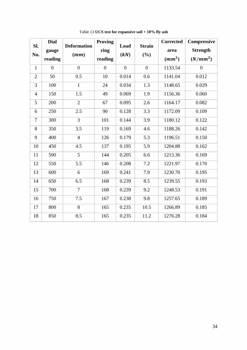
Table 13 UCS test for expansive soil + 10% fly ash
Sl.
No.
Dial
gauge
reading
Deformation
(𝒎𝒎)
Proving
ring
reading
Load
(𝒌𝑵)
Strain
(%)
Corrected
area
(𝒎𝒎𝟐)
Compressive
Strength
(𝑵/𝒎𝒎𝟐)
1 0 0 0 0 0 1133.54 0
2 50 0.5 10 0.014 0.6 1141.04 0.012
3 100 1 24 0.034 1.3 1148.65 0.029
4 150 1.5 49 0.069 1.9 1156.36 0.060
5 200 2 67 0.095 2.6 1164.17 0.082
6 250 2.5 90 0.128 3.3 1172.09 0.109
7 300 3 101 0.144 3.9 1180.12 0.122
8 350 3.5 119 0.169 4.6 1188.26 0.142
9 400 4 126 0.179 5.3 1196.51 0.150
10 450 4.5 137 0.195 5.9 1204.88 0.162
11 500 5 144 0.205 6.6 1213.36 0.169
12 550 5.5 146 0.208 7.2 1221.97 0.170
13 600 6 169 0.241 7.9 1230.70 0.195
14 650 6.5 168 0.239 8.5 1239.55 0.193
15 700 7 168 0.239 9.2 1248.53 0.191
16 750 7.5 167 0.238 9.8 1257.65 0.189
17 800 8 165 0.235 10.5 1266.89 0.185
18 850 8.5 165 0.235 11.2 1276.28 0.184
35
Table 14 UCS test for expansive soil + 20% fly ash
Sl.
No.
Dial
gauge
reading
Deformation
(𝒎𝒎)
Proving
ring
reading
Load
(𝒌𝑵)
Strain
(%)
Corrected
area
(𝒎𝒎𝟐)
Compressive
Strength
(𝑵/𝒎𝒎𝟐)
1 0 0 0 0 0 1133.54 0
2 50 0.5 11 0.015 0.6 1141.04 0.013
3 100 1 35 0.049 1.3 1148.65 0.043
4 150 1.5 71 0.101 1.9 1156.36 0.087
5 200 2 98 0.139 2.6 1164.17 0.119
6 250 2.5 109 0.155 3.3 1172.09 0.132
7 300 3 132 0.188 3.9 1180.12 0.159
8 350 3.5 153 0.218 4.6 1188.26 0.183
9 400 4 164 0.233 5.3 1196.51 0.195
10 450 4.5 170 0.242 5.9 1204.88 0.201
11 500 5 173 0.246 6.6 1213.36 0.203
12 550 5.5 177 0.252 7.2 1221.97 0.206
13 600 6 177 0.252 7.9 1230.70 0.204
14 650 6.5 178 0.253 8.5 1239.55 0.204
15 700 7 176 0.250 9.2 1248.53 0.201
16 750 7.5 175 0.249 9.8 1257.65 0.198
17 800 8 175 0.249 10.5 1266.89 0.196
18 850 8.5 174 0.248 11.2 1276.28 0.194
19 900 9 173 0.246 11.8 1285.80 0.191
36
Table 15 UCS test for expansive soil + 30% fly ash mixture
Sl.
No.
Dial
gauge
reading
Deformation
(𝒎𝒎)
Proving
ring
reading
Load
(𝒌𝑵)
Strain
(%)
Corrected
area
(𝒎𝒎𝟐)
Compressive
Strength
(𝑵/𝒎𝒎𝟐)
1 0 0 0 0 0 1133.54 0
2 50 0.5 6 0.008 0.6 1141.05 0.007
3 100 1 24 0.034 1.3 1148.65 0.029
4 150 1.5 48 0.068 1.9 1156.36 0.059
5 200 2 71 0.101 2.6 1164.17 0.086
6 250 2.5 93 0.132 3.3 1172.09 0.113
7 300 3 107 0.152 3.9 1180.12 0.129
8 350 3.5 128 0.182 4.6 1188.26 0.153
9 400 4 141 0.201 5.3 1196.51 0.168
10 450 4.5 147 0.209 5.9 1204.88 0.174
11 500 5 150 0.213 6.6 1213.36 0.176
12 550 5.5 151 0.215 7.2 1221.97 0.176
13 600 6 151 0.215 7.9 1230.70 0.175
14 650 6.5 150 0.213 8.5 1239.55 0.172
15 700 7 149 0.212 9.2 1248.53 0.170
16 750 7.5 148 0.211 9.8 1257.65 0.167
37
Table 16 UCS test for expansive soil + 40% fly ash mixture
Sl.
No.
Dial
gauge
reading
Deformation
(𝒎𝒎)
Proving
ring
reading
Load
(𝒌𝑵)
Strain
(%)
Corrected
area
(𝒎𝒎𝟐)
Compressive
Strength
(𝑵/𝒎𝒎𝟐)
1 0 0 0 0 0 1133.54 0
2 50 0.5 8 0.011 0.6 1141.05 0.01
3 100 1 21 0.030 1.3 1148.65 0.026
4 150 1.5 46 0.065 1.9 1156.36 0.057
5 200 2 71 0.101 2.6 1164.17 0.087
6 250 2.5 92 0.131 3.3 1172.09 0.111
7 300 3 114 0.162 3.9 1180.12 0.137
8 350 3.5 132 0.188 4.6 1188.26 0.158
9 400 4 140 0.199 5.3 1196.51 0.166
10 450 4.5 144 0.205 5.9 1204.88 0.170
11 500 5 145 0.206 6.6 1213.36 0.170
12 550 5.5 145 0.206 7.2 1221.97 0.169
13 600 6 145 0.206 7.9 1230.70 0.168
14 650 6.5 144 0.205 8.5 1239.55 0.165
15 700 7 143 0.203 9.2 1248.53 0.163
38
Table 17 UCS test for expansive soil + 50% fly ash mixture
Sl.
No.
Dial
gauge
reading
Deformation
(𝒎𝒎)
Proving
ring
reading
Load
(𝒌𝑵)
Strain
(%)
Corrected
area
(𝒎𝒎𝟐)
Compressive
Strength
(𝑵/𝒎𝒎𝟐)
1 0 0 0 0 0 1133.54 0
2 50 0.5 12 0.017 0.6 1141.05 0.015
3 100 1 36 0.051 1.3 1148.65 0.044
4 150 1.5 69 0.098 1.9 1156.36 0.085
5 200 2 92 0.1311 2.6 1164.17 0.112
6 250 2.5 104 0.148 3.3 1172.09 0.126
7 300 3 124 0.176 3.9 1180.12 0.149
8 350 3.5 130 0.185 4.6 1188.26 0.156
9 400 4 139 0.198 5.2 1196.51 0.165
10 450 4.5 141 0.201 5.9 1204.88 0.166
11 500 5 142 0.202 6.5 1213.36 0.166
12 550 5.5 142 0.202 7.2 1221.97 0.165
13 600 6 140 0.199 7.9 1230.70 0.162
14 650 6.5 140 0.199 8.5 1239.55 0.16
15 700 7 139 0.198 9.2 1248.53 0.158
16 750 7.5 138 0.196 9.8 1257.65 0.156
39
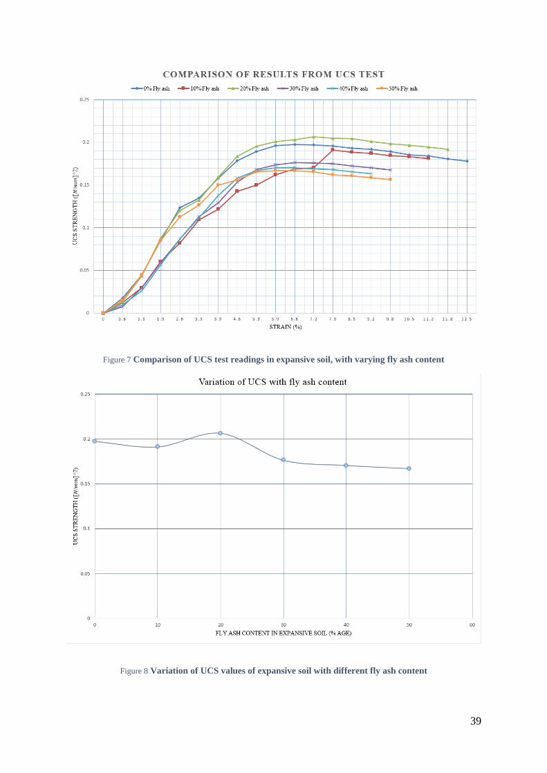
Figure 7 Comparison of UCS test readings in expansive soil, with varying fly ash content
Figure 8 Variation of UCS values of expansive soil with different fly ash content
40
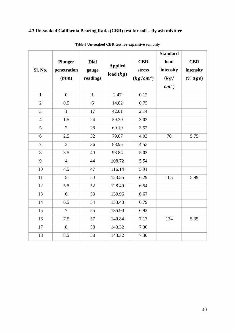
4.3 Un-soaked California Bearing Ratio (CBR) test for soil – fly ash mixture
Table 1 Un-soaked CBR test for expansive soil only
Sl. No.
Plunger
penetration
(𝒎𝒎)
Dial
gauge
readings
Applied
load (𝒌𝒈)
CBR
stress
(𝒌𝒈/𝒄𝒎𝟐)
Standard
load
intensity
(𝒌𝒈/
𝒄𝒎𝟐)
CBR
intensity
(% 𝒂𝒈𝒆)
1 0 1 2.47 0.12
2 0.5 6 14.82 0.75
3 1 17 42.01 2.14
4 1.5 24 59.30 3.02
5 2 28 69.19 3.52
6 2.5 32 79.07 4.03 70 5.75
7 3 36 88.95 4.53
8 3.5 40 98.84 5.03
9 4 44 108.72 5.54
10 4.5 47 116.14 5.91
11 5 50 123.55 6.29 105 5.99
12 5.5 52 128.49 6.54
13 6 53 130.96 6.67
14 6.5 54 133.43 6.79
15 7 55 135.90 6.92
16 7.5 57 140.84 7.17 134 5.35
17 8 58 143.32 7.30
18 8.5 58 143.32 7.30
41
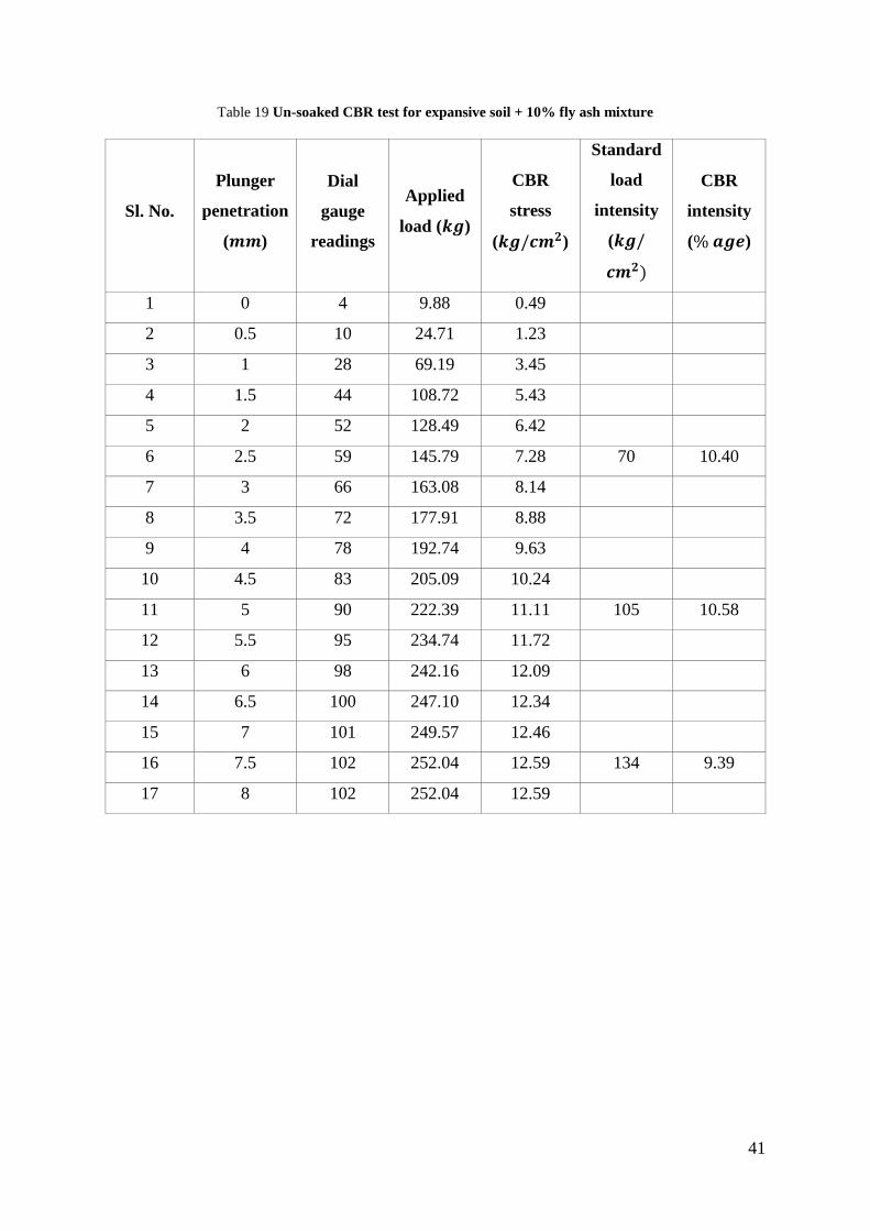
Table 19 Un-soaked CBR test for expansive soil + 10% fly ash mixture
Sl. No.
Plunger
penetration
(𝒎𝒎)
Dial
gauge
readings
Applied
load (𝒌𝒈)
CBR
stress
(𝒌𝒈/𝒄𝒎𝟐)
Standard
load
intensity
(𝒌𝒈/
𝒄𝒎𝟐)
CBR
intensity
(% 𝒂𝒈𝒆)
1 0 4 9.88 0.49
2 0.5 10 24.71 1.23
3 1 28 69.19 3.45
4 1.5 44 108.72 5.43
5 2 52 128.49 6.42
6 2.5 59 145.79 7.28 70 10.40
7 3 66 163.08 8.14
8 3.5 72 177.91 8.88
9 4 78 192.74 9.63
10 4.5 83 205.09 10.24
11 5 90 222.39 11.11 105 10.58
12 5.5 95 234.74 11.72
13 6 98 242.16 12.09
14 6.5 100 247.10 12.34
15 7 101 249.57 12.46
16 7.5 102 252.04 12.59 134 9.39
17 8 102 252.04 12.59
42
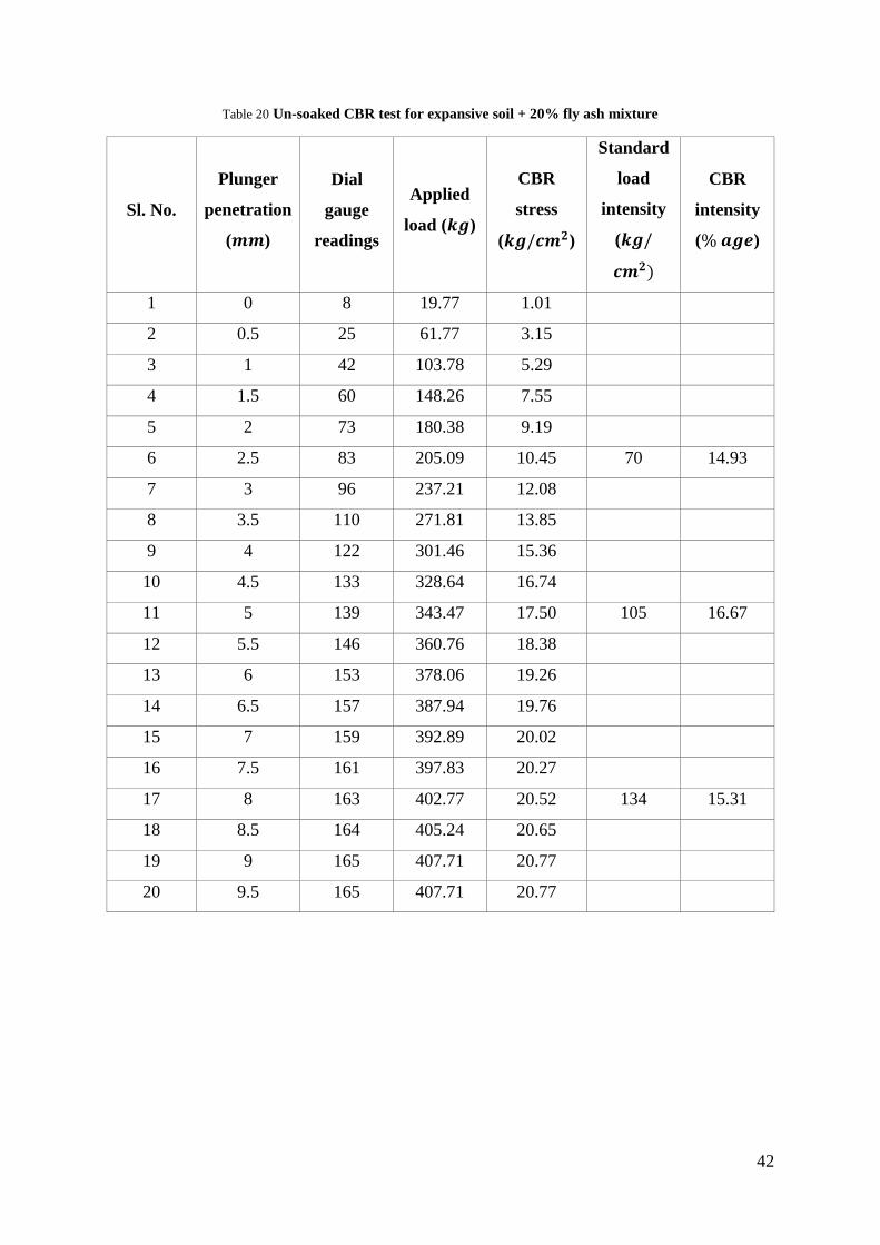
Table 20 Un-soaked CBR test for expansive soil + 20% fly ash mixture
Sl. No.
Plunger
penetration
(𝒎𝒎)
Dial
gauge
readings
Applied
load (𝒌𝒈)
CBR
stress
(𝒌𝒈/𝒄𝒎𝟐)
Standard
load
intensity
(𝒌𝒈/
𝒄𝒎𝟐)
CBR
intensity
(% 𝒂𝒈𝒆)
1 0 8 19.77 1.01
2 0.5 25 61.77 3.15
3 1 42 103.78 5.29
4 1.5 60 148.26 7.55
5 2 73 180.38 9.19
6 2.5 83 205.09 10.45 70 14.93
7 3 96 237.21 12.08
8 3.5 110 271.81 13.85
9 4 122 301.46 15.36
10 4.5 133 328.64 16.74
11 5 139 343.47 17.50 105 16.67
12 5.5 146 360.76 18.38
13 6 153 378.06 19.26
14 6.5 157 387.94 19.76
15 7 159 392.89 20.02
16 7.5 161 397.83 20.27
17 8 163 402.77 20.52 134 15.31
18 8.5 164 405.24 20.65
19 9 165 407.71 20.77
20 9.5 165 407.71 20.77

43
Table 21 Un-soaked CBR test for expansive soil + 30% fly ash mixture
Sl. No.
Plunger
penetration
(𝒎𝒎)
Dial
gauge
readings
Applied
load (𝒌𝒈)
CBR
stress
(𝒌𝒈/𝒄𝒎𝟐)
Standard
load
intensity
(𝒌𝒈/
𝒄𝒎𝟐)
CBR
intensity
(% 𝒂𝒈𝒆)
1 0 3 7.41 0.37
2 0.5 9 22.24 1.13
3 1 19 46.95 2.39
4 1.5 29 71.66 3.65
5 2 37 91.42 4.66
6 2.5 52 128.49 6.54 70 9.35
7 3 57 140.84 7.17
8 3.5 65 160.61 8.18
9 4 71 175.44 8.94
10 4.5 77 190.26 9.69
11 5 83 205.09 10.45 105 9.95
12 5.5 86 212.50 10.82
13 6 89 219.92 11.20
14 6.5 91 224.86 11.45
15 7 92 227.33 11.58
16 7.5 93 229.80 11.71 134 8.73
17 8 94 232.27 11.83
18 8.5 94 232.27 11.83
44
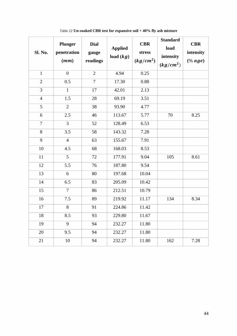
Table 22 Un-soaked CBR test for expansive soil + 40% fly ash mixture
Sl. No.
Plunger
penetration
(𝒎𝒎)
Dial
gauge
readings
Applied
load (𝒌𝒈)
CBR
stress
(𝒌𝒈/𝒄𝒎𝟐)
Standard
load
intensity
(𝒌𝒈/𝒄𝒎𝟐)
CBR
intensity
(% 𝒂𝒈𝒆)
1 0 2 4.94 0.25
2 0.5 7 17.30 0.88
3 1 17 42.01 2.13
4 1.5 28 69.19 3.51
5 2 38 93.90 4.77
6 2.5 46 113.67 5.77 70 8.25
7 3 52 128.49 6.53
8 3.5 58 143.32 7.28
9 4 63 155.67 7.91
10 4.5 68 168.03 8.53
11 5 72 177.91 9.04 105 8.61
12 5.5 76 187.80 9.54
13 6 80 197.68 10.04
14 6.5 83 205.09 10.42
15 7 86 212.51 10.79
16 7.5 89 219.92 11.17 134 8.34
17 8 91 224.86 11.42
18 8.5 93 229.80 11.67
19 9 94 232.27 11.80
20 9.5 94 232.27 11.80
21 10 94 232.27 11.80 162 7.28

45
Table 23 Un-soaked CBR test for expansive soil + 50% fly ash mixture
Sl. No.
Plunger
penetration
(𝒎𝒎)
Dial
gauge
readings
Applied
load (𝒌𝒈)
CBR
stress
(𝒌𝒈/𝒄𝒎𝟐)
Standard
load
intensity
(𝒌𝒈/𝒄𝒎𝟐)
CBR
intensity
(% 𝒂𝒈𝒆)
1 0 2 4.94 0.25
2 0.5 5 12.36 0.63
3 1 14 34.59 1.76
4 1.5 23 56.83 2.90
5 2 33 81.54 4.16
6 2.5 41 101.31 5.16 70 7.37
7 3 48 118.61 6.04
8 3.5 55 135.91 6.93
9 4 61 150.73 7.68
10 4.5 66 163.09 8.31
11 5 71 175.44 8.94 105 8.51
12 5.5 75 185.33 9.44
13 6 79 195.21 9.95
14 6.5 82 202.62 10.32
15 7 86 212.51 10.83
16 7.5 89 219.92 11.21 134 8.36
17 8 90 222.39 11.33
18 8.5 91 224.86 11.46
19 9 91 224.86 11.46
46
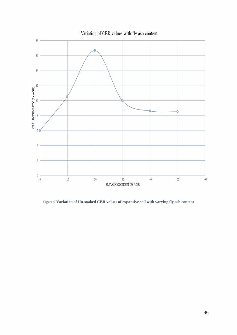
Figure 9 Variation of Un-soaked CBR values of expansive soil with varying fly ash content

47
4.4 Soaked California Bearing Ratio (CBR) test for soil – fly ash mixture
Table 24 Soaked CBR test for expansive soil
Sl. No.
Plunger
penetration
(𝒎𝒎)
Dial
gauge
readings
Applied
load (𝒌𝒈)
CBR
stress
(𝒌𝒈/𝒄𝒎𝟐)
Standard
load
intensity
(𝒌𝒈/𝒄𝒎𝟐)
CBR
intensity
(% 𝒂𝒈𝒆)
1 0 0 0.00 0.00
2 0.5 3 7.41 0.38
3 1 9 22.24 1.13
4 1.5 15 37.07 1.89
5 2 20 49.42 2.52
6 2.5 23 56.83 2.90 70 4.14
7 3 26 64.25 3.27
8 3.5 30 74.13 3.78
9 4 33 81.54 4.16
10 4.5 35 86.49 4.41
11 5 37 91.43 4.66 105 4.44
12 5.5 38 93.90 4.78
13 6 39 96.37 4.91
14 6.5 39 96.37 4.91
15 7 40 98.84 5.04
16 7.5 40 98.84 5.04 134 3.76
17 8 40 98.84 5.04

48
Table 25 Soaked CBR test for expansive soil + 10% fly ash mixture
Sl. No.
Plunger
penetration
(𝒎𝒎)
Dial
gauge
readings
Applied
load (𝒌𝒈)
CBR
stress
(𝒌𝒈/𝒄𝒎𝟐)
Standard
load
intensity
(𝒌𝒈/𝒄𝒎𝟐)
CBR
intensity
(% 𝒂𝒈𝒆)
1 0 2.47 0.13 2.47
2 0.5 9.88 0.50 9.88
3 1 19.77 1.01 19.77
4 1.5 29.65 1.51 29.65
5 2 39.54 2.01 39.54
6 2.5 51.89 2.64 70 3.78 51.89
7 3 61.78 3.15 61.78
8 3.5 71.66 3.65 71.66
9 4 79.07 4.03 79.07
10 4.5 84.01 4.28 84.01
11 5 88.96 4.53 105 4.32 88.96
12 5.5 91.43 4.66 91.43
13 6 93.90 4.78 93.90
14 6.5 96.37 4.91 96.37
15 7 96.37 4.91 96.37
16 7.5 96.37 4.91 134 3.66 96.37
49
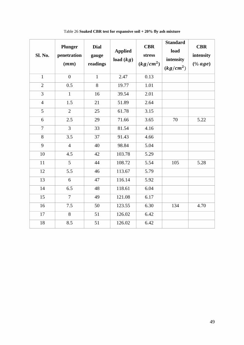
Table 26 Soaked CBR test for expansive soil + 20% fly ash mixture
Sl. No.
Plunger
penetration
(𝒎𝒎)
Dial
gauge
readings
Applied
load (𝒌𝒈)
CBR
stress
(𝒌𝒈/𝒄𝒎𝟐)
Standard
load
intensity
(𝒌𝒈/𝒄𝒎𝟐)
CBR
intensity
(% 𝒂𝒈𝒆)
1 0 1 2.47 0.13
2 0.5 8 19.77 1.01
3 1 16 39.54 2.01
4 1.5 21 51.89 2.64
5 2 25 61.78 3.15
6 2.5 29 71.66 3.65 70 5.22
7 3 33 81.54 4.16
8 3.5 37 91.43 4.66
9 4 40 98.84 5.04
10 4.5 42 103.78 5.29
11 5 44 108.72 5.54 105 5.28
12 5.5 46 113.67 5.79
13 6 47 116.14 5.92
14 6.5 48 118.61 6.04
15 7 49 121.08 6.17
16 7.5 50 123.55 6.30 134 4.70
17 8 51 126.02 6.42
18 8.5 51 126.02 6.42

50
Table 27 Soaked CBR test for expansive soil + 30% fly ash mixture
Sl. No.
Plunger
penetration
(𝒎𝒎)
Dial
gauge
readings
Applied
load (𝒌𝒈)
CBR
stress
(𝒌𝒈/𝒄𝒎𝟐)
Standard
load
intensity
(𝒌𝒈/𝒄𝒎𝟐)
CBR
intensity
(% 𝒂𝒈𝒆)
1 0 1 2.47 0.13
2 0.5 6 14.83 0.76
3 1 13 32.12 1.64
4 1.5 20 49.42 2.52
5 2 26 64.25 3.27
6 2.5 30 74.13 3.78 70 5.40
7 3 36 88.96 4.53
8 3.5 40 98.84 5.04
9 4 42 103.78 5.29
10 4.5 45 111.20 5.67
11 5 46 113.67 5.79 105 5.52
12 5.5 48 118.61 6.04
13 6 50 123.55 6.30
14 6.5 51 126.02 6.42
15 7 52 128.49 6.55
16 7.5 53 130.96 6.67 132 5.06
17 8 54 133.43 6.80
18 8.5 54 133.43 6.80
51
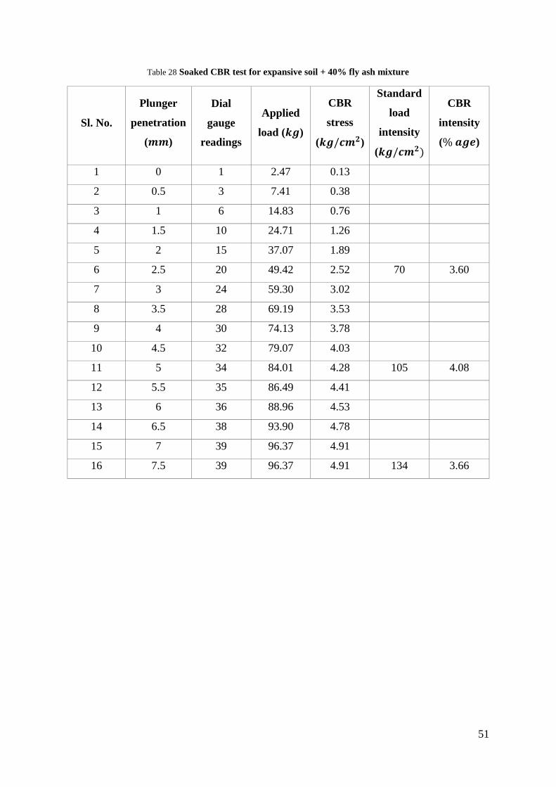
Table 28 Soaked CBR test for expansive soil + 40% fly ash mixture
Sl. No.
Plunger
penetration
(𝒎𝒎)
Dial
gauge
readings
Applied
load (𝒌𝒈)
CBR
stress
(𝒌𝒈/𝒄𝒎𝟐)
Standard
load
intensity
(𝒌𝒈/𝒄𝒎𝟐)
CBR
intensity
(% 𝒂𝒈𝒆)
1 0 1 2.47 0.13
2 0.5 3 7.41 0.38
3 1 6 14.83 0.76
4 1.5 10 24.71 1.26
5 2 15 37.07 1.89
6 2.5 20 49.42 2.52 70 3.60
7 3 24 59.30 3.02
8 3.5 28 69.19 3.53
9 4 30 74.13 3.78
10 4.5 32 79.07 4.03
11 5 34 84.01 4.28 105 4.08
12 5.5 35 86.49 4.41
13 6 36 88.96 4.53
14 6.5 38 93.90 4.78
15 7 39 96.37 4.91
16 7.5 39 96.37 4.91 134 3.66
52
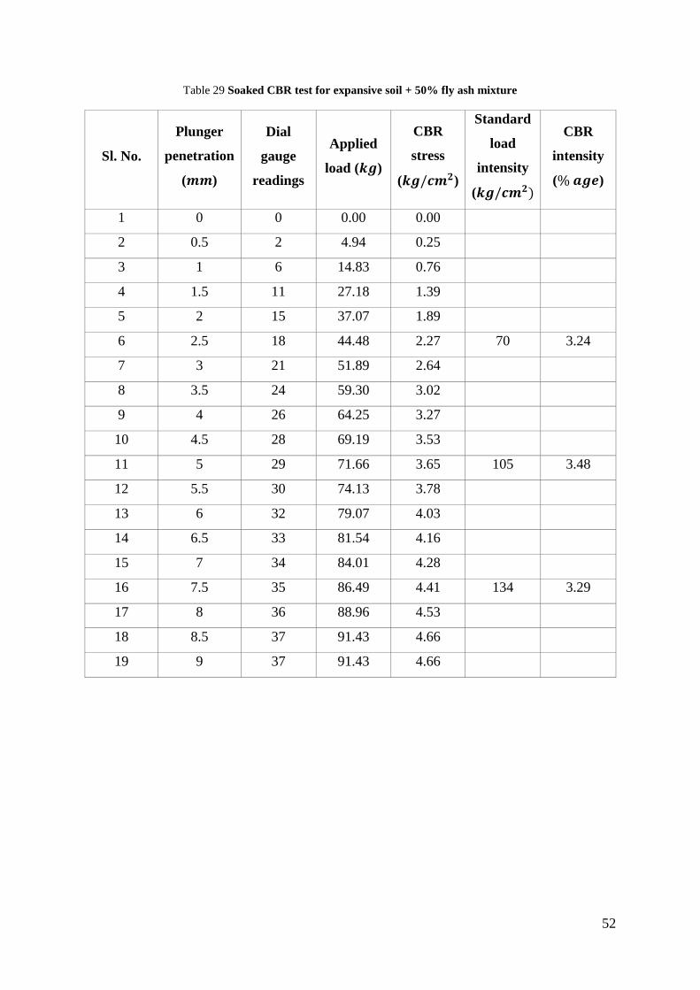
Table 29 Soaked CBR test for expansive soil + 50% fly ash mixture
Sl. No.
Plunger
penetration
(𝒎𝒎)
Dial
gauge
readings
Applied
load (𝒌𝒈)
CBR
stress
(𝒌𝒈/𝒄𝒎𝟐)
Standard
load
intensity
(𝒌𝒈/𝒄𝒎𝟐)
CBR
intensity
(% 𝒂𝒈𝒆)
1 0 0 0.00 0.00
2 0.5 2 4.94 0.25
3 1 6 14.83 0.76
4 1.5 11 27.18 1.39
5 2 15 37.07 1.89
6 2.5 18 44.48 2.27 70 3.24
7 3 21 51.89 2.64
8 3.5 24 59.30 3.02
9 4 26 64.25 3.27
10 4.5 28 69.19 3.53
11 5 29 71.66 3.65 105 3.48
12 5.5 30 74.13 3.78
13 6 32 79.07 4.03
14 6.5 33 81.54 4.16
15 7 34 84.01 4.28
16 7.5 35 86.49 4.41 134 3.29
17 8 36 88.96 4.53
18 8.5 37 91.43 4.66
19 9 37 91.43 4.66
53
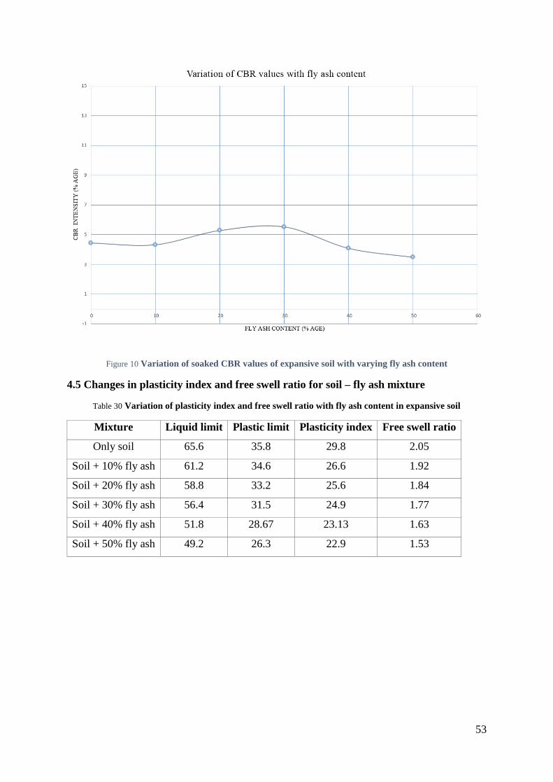
Figure 10 Variation of soaked CBR values of expansive soil with varying fly ash content
4.5 Changes in plasticity index and free swell ratio for soil – fly ash mixture
Table 30 Variation of plasticity index and free swell ratio with fly ash content in expansive soil
Mixture Liquid limit Plastic limit Plasticity index Free swell ratio
Only soil 65.6 35.8 29.8 2.05
Soil + 10% fly ash 61.2 34.6 26.6 1.92
Soil + 20% fly ash 58.8 33.2 25.6 1.84
Soil + 30% fly ash 56.4 31.5 24.9 1.77
Soil + 40% fly ash 51.8 28.67 23.13 1.63
Soil + 50% fly ash 49.2 26.3 22.9 1.53
54
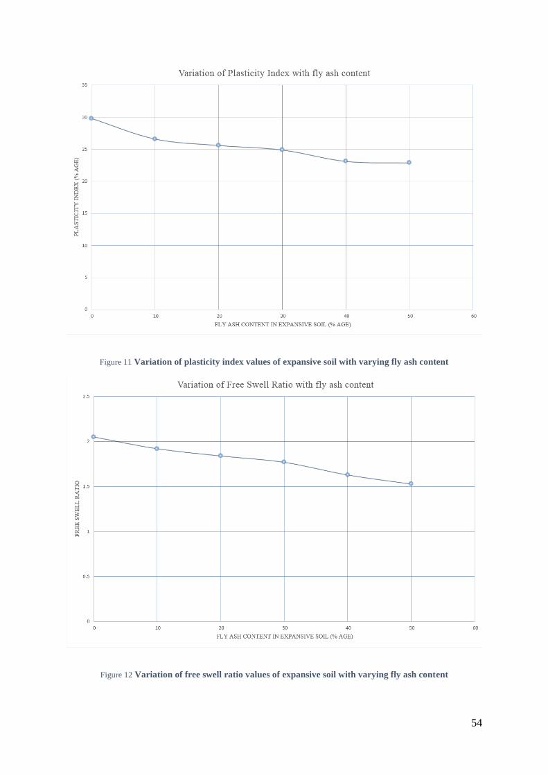
Figure 11 Variation of plasticity index values of expansive soil with varying fly ash content
Figure 12 Variation of free swell ratio values of expansive soil with varying fly ash content
55
4.8 Discussions
Black cotton soil is combined with altering percentage of fly ash (from 0% to 50%,
intervals in multiples of 10) by weight to observe its effect as an additive on the
expansive soil.
Maximum Dry Density (MDD) was found to change with varying content of fly. The
highest value observed being at fly ash content of 30% by weight.
The change in Unconfined Compressive Strength (UCS) of the soil with varying
content of fly ash is observed. The graph shows the variation of UCS with changing fly
ash content. The maximum value of UCS was obtained with the mixture of soil and
20% fly ash content by weight.
Both un-soaked and soaked California Bearing Ratio (CBR) tests are conducted with
varying content of fly ash in the black cotton soil. From the graphical comparison of
these values against the varying fly ash content, it can be observed that 20% fly ash and
30% fly ash content gave the maximum value of CBR intensity in un-soaked and soaked
soil-fly ash mixture respectively.
The liquid limit and plastic limit of the soil-fly ash mixture varied with the changing
fly ash content. Plasticity index values were computed from these experiments, which
showed a consistent decreasing pattern with the increase of fly ash content.
From the free swell ratio tests on the soil-fly ash mixture, the value of free swell ratio
decreased with the increasing fly ash content.

56
Chapter 5
CONCLUSION
57
5.1 Conclusions
Based on the results obtained and comparisons made in the present study, the following
conclusions can be drawn:
The Maximum Dry Density (MDD) value of the black cotton soil initially decreased
with the addition of fly ash. Then, it showed increment with increasing fly ash content
in the soil-fly ash mixture. The maximum value of MDD was observed for a mixture
of soil and 30% of fly ash content by weight. The MDD values consistently decreased
thereafter.
The Unconfined Compressive Strength (UCS) of the soil with variation of fly ash
content showed similar trend as that of the MDD values, except the fact that the peak
value was observed for a fly ash content of 20% by weight.
In un-soaked California Bearing Ratio (CBR) tests of soil conducted with varying fly
ash content, the CBR increased gradually with the increase in fly ash content till its
valuation was 20% by weight of the total mixture; it decreased thereafter.
The change in case of soaked California Bearing Ratio (CBR) tests of soil with varying
fly ash content was, however, uneven. It decreased with the initial addition of fly ash
(10% by weight of total mixture), and then increased till fly ash content reached 30%
by weight of total mixture. The values decreased thereafter.
With the increasing fly ash content in the soil-fly ash mixture, the decrease in value of
free swell ratio was remarked. This decrease was also reciprocated by the plasticity
index values. Plasticity index values are directly proportional to percent swell in an
expansive soil, thus affecting the swelling behavior of the soil-fly ash mixture.
Thus, fly ash as an additive decreases the swelling, and increases the strength of the
black cotton soil.

58
5.2 Scope for future study
Fly ash along with another additive like lime, murrum, cement, and other such materials
can be used together, and may be varied in quantity to obtain the best possible
stabilizing mixture.
59
REFERENCES
Bose, B. (2012), “Geo-engineering Properties of Expansive Soil Stabilized with Fly
Ash”, Electronic Journal of Geotechnical Engineering, Vol. 17, pp. 1339-1353.
Cokca, E. (2001), “Use of Class C fly ash for the stabilization of an expansive soil”,
ASCE Journal of Geotechnical and Geoenvironmental Engineering. Vol. 127, Issue 7,
pp. 568–573.
Holtz, W. G., and Gibbs, H. J. (1956), “Engineering properties of expansive clays”
Transactions ASCE. Vol. 121, pp. 641–677.
Kumar, A., Walia, B.S., and Bajaj, A. (2007), “Influence of Fly Ash, Lime and
Polyester Fibers on Compaction and Strength Properties of Expansive Soil”, Journal
of Materials in Civil Engineering, Vol. 19, Issue 3, pp. 242-248.
Malik, A., and Thapliyal, A. (2009), “Eco-friendly Fly Ash Utilization: Potential for
Land Application”, Critical Reviews in Environmental Science and Technology, Vol.
39, Issue 4, pp. 333-366.
Misra, A., Biswas, D., and Upadhyaya, S. (2005), “Physico-mechanical behavior of
self-cementing class C fly ash-clay minerals”, J. Fuel, Vol. 84, pp. 1410-1422.
Nath., P., and Sarker, P. (2011), “Effect of Fly Ash on the Durability Properties of High
Strength Concrete”, Procedia Engineering, Vol. 14, pp. 1149-1156.
Phanikumar, B.R. and Sharma, R. S. (2004), “Effect of Fly Ash on Engineering
Properties of Expansive Soil”, Journal of Geotechnical and Geoenvironmental
Engineering. Vol. 130, Issue 7, pp. 764-767.
Phanikumar, B. R., Naga Reddayya, S. and Sharma, R. S. (2001), “Volume Change
Behavior of Fly Ash Treated Expansive Soils”, 2nd International Conference on Civil
Engineering, Indian Institute of Science, Bangalore, India. Vol. 2, pp. 689–695.
60
Phanikumar, B.R., and Sharma, R. (2007), “Volume Change Behavior of Fly Ash-
Stabilized Clays”, Journal of Materials in Civil Engineering, Vol. 19, SPECIAL
ISSUE: Geochemical Aspects of Stabilized Materials, pp. 67–74.
Phanikumar, B.R. (2009), “Effect of Lime and Fly Ash on Swell, Consolidation and
Shear Strength Characteristics of Expansive Clay: A comparative study”, Journal of
Geomechanics and Geoengineering: An international journal, Vol. 4, Issue 2, pp. 175-
181.
Prakash, K., and Sridharan, A. (2009), “Beneficial Properties of Coal Ashes and
Effective Solid Waste Management”, Practice Periodical of Hazardous, Toxic, and
Radioactive Waste Management, ASCE, Vol. 13, Issue 4, pp. 239-248.
Radhakrishnan, G., Kumar, M.A., and Raju, G.V.R.P. (2014), “Swelling Properties of
Expansive Soils Treated with Chemicals and Fly ash”, American Journal of
Engineering Research. Vol. 3, Issue 4, pp. 245-250.
Raut, J.M., Bajad, S.P., and Khadeshwar, S.P. (2014), “Stabilization of Expansive Soils
Using Fly ash and Murrum”, International Journal of Innovative Research in Science,
Engineering and Technology. Vol. 3, Issue 7.
Satyanarayana P.V.V., Kumar, S.H., Praveen, P., Kumar, B.V.S. (2013), “A Study on
Strength Characteristics of Expansive Soil-Fly ash Mixes at Various Moulding Water
Contents”, International Journal of Recent Technology and Engineering. Vol. 2, Issue
5.
Senol, A., Etminan. E., and Olgun, C. (2012), “Stabilization of Clayey Soils Using Fly
Ash and Homopolymerpolypropylene”, GeoCongress, pp. 3929-3938.
Sridharan, A., Pandian, N. S., and Rajasekhar, C. (1996), “Geotechnical
Characterization of Pond Ash, Ash ponds and Disposal Systems, Narosa Publising
House, New Delhi, India, pp. 97–110.

61
Xing, C., and Ji-ru, Z. (2002), “Stabilization of Expansive Soil by Lime and Fly Ash”,
Journal of Wahan University of Technology – Mater. Sci. Ed., Vol. 14, Issue 4, pp. 73-
77.
Zha, F., Liu, S., Du, Y., and Cui, K. (2008), “Behavior of Expansive Soils Stabilized
with Fly Ash”, Natural Hazards, Vol. 47, Issue 3, pp. 509-523.