stability of small single-phase synchronous motors - philips bound... · philips tech. rev. 33, no....
TRANSCRIPT

Philips tech. Rev. 33, 235-243,1973, No. 8/9 235
Stability of small single-phase synchronous motors
H. Schern mann
Introduetion
Electrical equipment nowadays does much of thework in and about the house that was formerly donemanually. Electric power is used on a large scale forwashing machines, vacuum cleaners and shavers, andalso for tape recorders and record players. This hasall become possible because such household machineshave certain features in common: they are all simpleto use, cheap to produce, use little power and arerelatively cheap to service. J n almost all cases thedevices are required to operate from the ordinarysingle-phase mains su pply.
For household use in the broadest sense, electricalenergy is transforrned into mechanical energy mainlyby single-phase electric motors. Well known types ofmotors are synchronous and induction motors withtheir starting circuits, and hysteresis and series mo-tors [1]. Their reliability, cost and efficiency must ofcourse match the requirements of the devices in whichthey are used.
The development of oriented permanent-magnetmaterials with a high coercivity, such as ferroxdure,has led to the suggestion that synchronous motors withpermanent-magnet rotors might offer advantages withregard to design, characteristics or efficiency. Suchmotors have no need for a commutator (which is sub-ject to wear), they cause no electrical interference andthey have a constant speed. Moreover, their efficiencycan be high and the motor can be constructed from asmall number of relatively simple components. Fig. Ishows the principle of such a motor [2l. A laminatedstat or is provided with a coil that can be directly con-nected to the mains. A permanently magnetized rotorof ferroxdure with two diametrically opposed poles ismounted on a shaft in the stator field and can be usedto drive some external load.
When the voltage is switched on, the motor shouldbe self-starting and it should then rotate steadily in thesame direction. Our permanent-magnet synchronousmotors, like synchronous motors in general, do notmeet these requirements unless special measures aretaken. A well known and generally used method ofstarting a single-phase synchronous motor is the useof an auxiliary coil to give a rotating field, in combina-
D,. H. SChel11l11al111is with Philips ForschungslaboratoriumAachen G mb H, Aachen.
tion with an induction cage or a hysteresis cylinder onthe rotor. In this way the motor can start to rotateasynchronously in one direction. This solution, how-ever, requires modifications to both the rotor and thestator and should therefore be avoided if possible.
Another difficulty in purely single-phase motors isthat while the stator field does in fact change sign it hasa fixed direction: it does not rotate, as in rotating-fieldmotors. The direction of rotation of such a single-phase motor is therefore indeterminate.
Fig. I. Principle of a single-phase synchronous motor with a per-manent-magnet rotor. R rotor, magnetized in the direction 8,·.S stator. f) angular coordinate defining thc rotor position.
Furthermore, a synchronous motor can behave asan oscillating system because there is an elastic coup-ling between the rotor and the rotating stator field. Ifthe damping in this system is too small, oscillations canbe set up that allow the motor to fall out of step withthe field. With a non-conducting rotor, as in the presentdiscussion, there is no electrical damping in the rotorat all. The stability of the rotary motion therefore re-quires special attention in such motors.
The advantages mentioned above were howeversufficient to indicate a further study of these problems.In this article particular attention will be paid to thestarting and stability of the motor.
[1] E. M. H. Kamerbeek, Electric motors, this issue, p. 215.[2] R. Thees, Philips tech. Rev. 26, 143, 1965 and Elektrotechn.
Z. A 87,171,1966.

236 H. SCHEMMANN Philips tech. Rev. 33, No. 8/9
StartingNormal polyphase synchronous motors with no
damping or starting cage will not in general start torotate unaided when the stator winding of the station-ary motor is connected to the supply. The polyphasesupply produces a synchronously rotating field imme-diately but owing to its inertia the rotor cannot usuallyfollow this field [3l. There are now two ways of rem-edying this situation. The motor can be brought up tospeed mechanically from outside or the frequency ofthe supply voltage can be reduced until the rotor isin step with the field; the frequency is then increasedslowly until the rotor reaches the desired speed.
In single-phase synchronous motors an auxiliaryfield is usually excited, as mentioned above, whichcombines with the main field to give a rotating mag-netic field. This can be produced by means of an auxil-iary winding on the stator, connected to the supply viaa capacitor, or by including one or two short-circuitedturns around part of the stator poles (shaded pole) 14l.
Electric motors with a large moment of inertia or highspeed usually run asynchronously during starting, thatis to say, starting takes place by virtue of currentsinduced in the rotor by the stator field. Starting ofhysteresis motors will not be discussed here.
Single-phase synchronous motors with a non-conducting permanent-magnet rotor cannot be startedby any of the methodsjust mentioned. When the supplyis switched on the rotor is subject only to an alternatingfield that only changes sign; it does not change direc-tion. This field exerts a torque on the rotor only whenthe rotor field and the stator field do not lie exactly inthe same direction. Their directions coincide twice perrevolution; the rotor must be prevented from comingto rest in either of these two positions since it wouldthen remain there.
The rotor of the motor shown in fig. I is su bject notonly to a torq ue exerted by the stator field but also to amagnetic torque (the reluctance torque) even whenthere is no current in the stator winding. This is becausethe total magnetic energy of the system depends on theorientation of the rotor magnet between the statorpoles. This reluctance torque can be used to preventthe rotor from coming to rest with its field parallel tothe stator field. This is just what does happen in asymmetrical configuration like that of fig. 1. If howeverthe space between the stator poles is made asymmetricalso that the air gaps between rotor and stator along onediameter are smaller than those along another diam-eter (fig. 2) then the rotor will assume a rest positionin which the magnetic resistance is at a minimum. Thestator field is hardly affected by the above asymmetry:to the stator the rotor appears to be part of the air gapbecause of the relatively low permeability of the rotor
material. If to is the amplitude ofthe reluctance torqueand y the angle between the rest position (determinedby the reluctance torque and the direction of thestator field [5l then the torque acting on the rotor inthe undesired 'parallel-field' position is To = to sin 2y.If the rotor is in fact to be moved from this undesiredposition, then To must be larger than the total friction-al torque Tr r acting on the shaft of the rotor.
In the electric motors considered here, the criticalfrictional torque is much smaller than the maximumtorque of the motor. These motors are therefore onlysuitable in applications where the external frictionaltorque at the instant of starting is not too large.
Now let us consider the starting process in more de-tail. The behaviour encountered here is different from
Fig.2. Configuration of a single-phase motor with asymmetriestator poles. A motor like this is self-starting. R rotor. S stator.
the well known starting effects in asynchronous or d.c.motors; in these motors the rotor beg ins to rotate inone particular direction and then rotates faster andfaster in that direction. In the single-phase synchronousmotors considered here there is in general a complicat-ed aperiodic transient behaviour. As fig. 3 shows, theangular velocity is alternately positive and negative:the motor thus changes its direction continually. Thisirregular movement continues until the variables ofthe motion (speed, rotor position with respect to stat orfield, stator current and phase angle of this current)have adjusted themselves to the values correspondingto uniform rotation. The final direction of rotationdepends on the initial conditions: in a given situationthe phase of the voltage at the instant of switching onis particularly important.

Philips tech. Rev. 33, No. 8/9 SINGLE-PHASE SYNCHRONOUS-MOTOR STABILITY 237
Fig.3. Starting behaviour of a single-phase synchronous motor with a pannenent-magnetrotor. The angular velocity is plotted as a function of time for various values of the phaseangle e of the supply voltage at the instant of switching on. The starting behaviour and thedirection of rotation are affected by this phase angle but the motional state finally achievedis always the same.
A motor behaves in the manner shown in fig. 3 onlywhen the moment of inertia of the rotor and the loadattached to it is not too great. If the combined momentof inertia is too great the rotor will only oscillate aboutan equilibrium position. In general it is not possibleto start a single-phase synchronous motor by a gradualincrease in the frequency of the supply voltage.
This rather summary discussion of methods for self-starting shows that a single-phase synchronous motorwith a permanent magnet rotor can only be used todrive devices with a low static friction or which arecoupled to the motor only after it has started. More-over, the device to be driven must have a small mo-ment of inertia and the direction of rotation must beunimportant.
The limitations imposed by the requirements of asmall frictional torque and a low moment of inertiacan largely be overcome by the use of a mechanicalcoupling that reduces the mechanical load on themotor to an acceptable value during starting. A num-ber of schemes have been investigated, all dependingon frictional effects. In the design of such couplings itis especially important that there should be no slip inthe coupling after starting, for this would mean thatthe mechanical power of the motor could not be fullyused.If necessary the direction of rotation can be predeter-
mined by means of a mechanical device that preventsrotation in one direction. In each case these extracomplications must be weighed against the likely ad-vantages.
Experimental investigation of the motor behaviour
We shall now examine the behaviour of a single-phase synchronous motor with a permanent-magnetrotor that has run up to speed after switching on and
does not, as described above, remain stationary or justperform small-amplitude oscillations. An electric mo-tor is only suitable for practical applications if once ithas started it continues to rotate in the same directionwith little variation in speed. It can be shown that toachieve this, the parameters of the motor, the supplyvoltage and the load must be matched to each otherbetween fairly narrow limits. If this is not the case, aperturbed motion will ensue that differs considerablyfrom the desired unperturbed motion [6]. A goodoverall picture of the possible rotor motions can bederived from measurements of angular velocity as afunction of time for various amplitudes of the supplyvoltage. Table I (p. 239) shows the results of such meas-urements on a motor designed for a voltage of 220 V,which therefore rotates with an unperturbed motion atthis voltage. There are, however, at this voltage speedvariations at twice the mains frequency. This modu-lation of the rotational speed is due to periodic varia-tions in the electromagnetic torque. In a purely single-phase synchronous motor, there is a field that rotatesin the opposite direction to the rotor at twice the mainsfrequency and thus gives rise to an oscillating torqueat this frequency [7]. For a motor of other dimensionsor with another load, however, the various perturbedmotions may take place at the nominal voltage.
The angular velocity is measured by means of aunipolar generator, which has negligible effect on thebehaviour of the motor. In the diagrams in Table I the
[3J See for example R. Richter, Elektrische Maschinen, part I,3rd edition, Birkhäuser Verlag, Basel 1967, p. 63.
[4J Further details are given on p. 229 of the article by E. M. H.Kamerbeek [IJ.
[5J The angle y is the difference between the angles a and fJdefined by Kamerbeek [IJ.
[6J Definitions of the terms used here are given in J. G. Malkin,Theorie der Stabilität einer Bewegung, Oldenbourg, München1959, p. 3.
[7J See p. 220 of the article by Kamerbeek [IJ.

238 H. SCHEMMANN Philips tech. Rev. 33, No. 8/9
angular velocity is plotted as a function of time. Thegraphs refer to the motion after starting transients havedied away.The phase of the voltage at the instant of switching
on usually has no effect on the final rotation of therotor; the situations 6 and 7 in Table I are exceptions.The experiments show that the single-phase syn-
chronous motor with the permanent-magnet rotordescribed has a useful motion only within a limitedvoltage range or, more correctly, in a limited range ofmotor parameters. The extent of this range and its lim-its are of course of interest. It should be rememberedhere that the motors must retain their unperturbedmotion in spite of the spread in properties thatnormally occurs in industrial materials or as a result ofthe production process. The motors must also be ableto take a load. Another interesting point is the extentto which the behaviour of the motor may be affectedby nonlinear effectssuch as the saturation of the statoriron.An attempt will be made to examine these questions
using the equations of motion discussed in the nextsection, which describe the dynamic behaviour of themotor.
Equations of motion
A theoretical model of the situation must alwayssatisfy two conditions. Firstly, it should allow thevarious relevant characteristics to be represented withsufficient accuracy. Secondly, the model must give aclear physical picture and it must be easy to manipulate.This second requirement means that simplificationshave to be introduced and certain things neglected, inthe hope, however, that nothing essential is lost. In themodel of our motor it has been assumed that themagnetic state of the motor is uniquely determined bythe stator current and the rotor position, in other wordsthat hysteresis effects are completely neglected. Fur-thermore, saturation effects and eddy currents in theiron of the stator are neglected and the friction isassumed to depend linearlyon the normal forces andto be independent of velocity (Coulomb friction).Finally it is assumed that the magnetic flux and thereluctance torque vary sinusoidally with the rotorposition.On the .basis of these assumptions it is not difficult
to write down the equations of motion. The first equa-tion states that the sum of the voltages across the statorwinding must be equal to the mains voltage. The sumis made up of the iR drop due to the current i throughthe coilof resistance R, the voltage Ldi/dt due to in-ductance L of the coil and finally the voltage d<Psr/dtinduced in the stator coil as a result of the change in
the flux <Psrof the rotor linked by the stator coil.The latter contribution is proportional to the angularvelocity (J of the rotor and is a sinusoidal function ofthe rotor position. The equation for the voltage acrossthe stator coil is therefore:
A di ,11 11v sin (Wmt + e) = iR+L- + 'Psrr;sin 8,
dt
where Wm is the angular frequency of the mains voltageand e its phase angle.The second equation for the motor behaviour comes
from the condition that the sum of the torques actingon the rotor must be zero. Apart from the frictionaltorque Tcr and the reluctance torque To there is also anelectromagnetic torque acting on the rotor, which isproportional to the stator current and to the rotor flux.The values of these torques must together be equal tothe rate of change të of the angular momentum:
i&sr sin 8 - Tcr - To = lii .
The initial conditions of this equation are that at theinstant the voltage is switched on (t = 0) the current iszero and the rotor is in the position 8 = y, i.e. theposition for static equilibrium.
In spite of the relatively simple form ofthe equationsthere is no general method for solving them. This isbecause of the nonlinearities that occur in the equa-tions. (In the first equation the product (J sin 8, in thesecond i sin 8.) Attempts to linearize the equationsyield no clear picture of the real situation; indeed theobserved instabilities are probably directly due to thesenonlinearities.
The equations have therefore been solved by meansof an analog computer. This method gives a directphysical picture of the behaviour of the model. A moreaccurate solution on a digital computer is.lessattractivesince programs for the solution of nonlinear differentialequations require a great deal of computing time.
In the analog calculation a model with the same dif-ferential equations as the electric motor under inves-tigation is set up in the computer. The operations suchas summation, integration and multiplication are carriedout by operational amplifiers. Important quantities canbe read off during the calculations from instrumentsconnected at appropriate points in the circuit [81.
The form of the theoretical model is determined bythe equations of motion. To simulate a given motor,the various parameters of the motor must be deter-mined and from these the coefficients of the equationsmust be derived. It should be noted that the inductance
[S) A description of the analog computer used is given in:H. Schemmann, Thesis, Eindhoven 1971, also published asPhilips Res. Repts. Suppl. 1971, No. 5 (in German).

Philips tech. Rev. 33, No. 8/9 SINGLE-PHASE SYNCHRONOUS-MOTOR STABILITY 239
Table J. Typical curves for the motion of a single-phase synchronous motor witha permanent-magnet rotor, arranged in increasing values of the supply voltage.
__.. tiT
125V
135V
145V
166V
166V
220V
265V
1. At lowvoltages the motor does not start. The rotorvibrates about theequilib-rium position defined by the reluctance torque. (The same situation arises atthe nominal voltage if the moment of inertia is too large.)
2. The rotor rotates but the motion is very irregular. The motion is not uni-directional even though the synchronous angular velocity is sometimesmomentarily exceeded. The rotor changes its direction of rotation in a quiteirregular manner.
3. The rotation has now become unidirectional. However, there are quite largeperiodic variations superimposed on the synchronous speed. Stroboscopicobservations show that a steady-state motion is achieved with a repetitionperiod of two revolutions of the rotor (25 Hz perturbation).
4. As the voltage is increased further the irregularities of the motion do notdecrease. On the contrary, large new irregular and aperiodic motions occurin which the rotor again keeps reversing its direction of rotation. Apart fromthe voltage at which it occurs, this situation is no different from that de-scribed under 2.
5. When the voltage is increased still further, the motion becomes unidirectionalagain. Strong periodic variations are still present (hunting) but the motorruns with a mean speed equal to the synchronous value.
6. The amplitude of the hunting now becomes smaller; above a particular volt-age the oscillations disappear entirely. For the first time the motor assumesits state of unperturbed rotation as at the nominal voltage (see 8).
7. At the same voltage at which this unperturbed motion occurs, however, therotor can also run with very large speed variations. The rotor periodicallycomes almost to rest; the mean rotor speed is, however, the synchronousvalue. These variations are repeated every It periods (33t Hz perturbation).Which of the two states of motion, 6 or 7, takes place is determined by thephase of the supply voltage at the instant the motor is switched on. .
8. At the nominal voltage the rotation is again unperturbed. The angularvelocity is now modulated only at twice the mains frequency. The modula-tion in speed is 20-40% of the mean synchronous value. If a large momentof inertia is coupled to the motor, the modulation depth becomes smaller.The unperturbed motion is stable for voltage variations that are not toolarge, and the motor can drive a load.
9. Increasing the voltage above the nominal value again gives rise to largevariations in the angular velocity. The rotor comes to rest once per revolutionand the direction of motion may even be momentarily reversed. Withinmilliseconds the rotor then assumes velocities far above the synchronousvalue and is then immediately slowed down (50 Hz perturbation).If still higher voltages are applied, the accelerating torques are so large
that any regular motion is quite impossible.

240 H. SCHEMMANN Philips tech. Rev. 33, No. 8/9
of the stator coil(s) and the value of the rotor flux mustbe determined under conditions that approach theactual working conditions as nearly as possible. Thisis necessary because in the equations of motion a linearrelation has been assumed between stator current andstator field and in practice this is not the case.
very good. The 50 Hz perturbation, the unperturbedrange and also the 331 Hz perturbation and its adjacenttransition region occur in the model at almost the samevoltages at which they are observed in practice. Atvoltage, less than 160 V it is noticeable that the modelexhi bits less tendency to oscillation than is observed in
9Fig.4. Rotor motion after starting transients have died away, determined by an analog com-puter. The curves 1, ..... 9 show the behaviour as the supply voltage is increased; curve8 refers to the nominal voltage. The types of motion agree qualitatively very well with theresults measured on a practical motor, as given in Table I.
Before conclusions can be drawn from the model,it must be established that, in essentials, the modeldescribes the real situation sufficiently well. This pointhas been investigated by determining how the modeldescribes the angular velocity as a function of timeafter switching on the voltage, as was done earlier forthe motor itself.
The results are shown in fix 4. Comparison of theseresults with the results of the measurements on themotor, as given in Table I, show that the equationsrepresent a behaviour completely analogous to that ofthe motor. Not only do the equations reproduce thedetails of the motion observed in the motor but thereare no extraneous effects, i.e. effects not observed inthe motor. This implies that neither the perturbedmotion nor the unperturbed motion are caused byeffects that have been neglected in the formulation ofthe model.If the voltages corresponding to the limits between
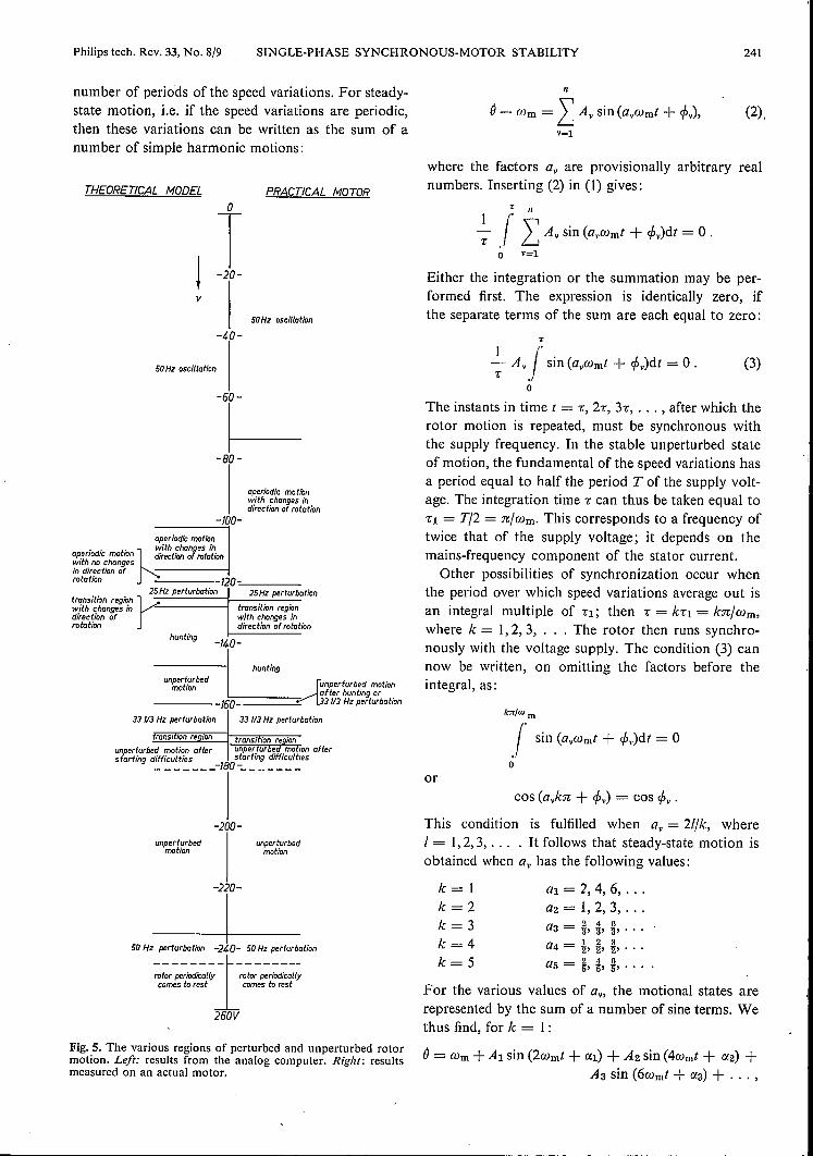
the regions of perturbed and unperturbed motion arecompared, the following conclusions can be drawn(seefig. 5). Particularly at voltages above 160 V, whichis the range of most interest, the agreement between thecalculated behaviour and the observed behaviour is
practice. This difference is connected with the fact thatthe curvature was neglected in the magnetizationcharacteristic of the stator iron. Since voltages below160 V are of little practical importance, it is not nec-essary to revise the model in this connection. Apartfrom this the choice of the model is seen to be justifiedby the results.
Periodic solutions of the equations of motion
We have seen that the motor can rotate with a con-stant mean speed. Superimposed on this mean value arelarge periodic variations with frequencies that aresimply related to the supply frequency.
In general a synchronous motor, once started, mustrun at a constant mean speed; for a rotor with twopoles the mean speed must correspond to the frequencyof the supply. This means that the mean of the speedvariations over a long time must be zero, or
1 (' de- (--wm)dt=O,T.I dl
o
where the integration time T extends over an integral
(1)
Philips tech. Rev. 33, No. 8/9 SINGLE-PHASE SYNCHRONOUS-MOTOR STABILITY 241
number of periods of the speed variations. For steady-state motion, i.e. if the speed variations are periodic,then these variations can be written as the sum of anumber of simple harmonic motions:
THEORETICAL MODEL PRACTICAL MOTOR
r! -20-
v
50Hz oscillation
-40-50 Hz oscillation
-60-
~-80-
aperiodic ma tioflwith changes indirection of rotation
____ -~100-aperiodic motion
" . with changes inaperiodic motIOn ~irection of rotationwith no changesin direction ofrotation 120--=------_
25 Hz perturbationtransition regionrwith changes indirection ofrotation
hunting
25Hz perturbation
transition regionwith changes indirection of rotation
-f4.0-
huntingunperturbed
motion
33 113Hz perturbation 33 113Hz perturbation
unperturbed motion after unper. ur e_d.ma Ion afterstarting difficulties startmg difficulties_______ -180- _
-200-unperturbed unperturbed
motion motion
-220-
50 Hz=:':-1-~40~~o~~:r~u~~ationrotor periodically rotor periodicallycomes to rest comes to rest
260V
Fig. 5. The various regions of perturbed and unperturbed rotormotion. Left: results from the analog computer. Right: resultsmeasured on an actual motor.
11
é - Wm =IAv sin (avwmt + rpv),v=l
(2),
where the factors a; are provisionally arbitrary realnumbers. Inserting (2) in (1) gives:
T 11+ .r IAv sin (avwmt + rpv)dt = 0 .o v=l
Either the integration or the summation may be per-formed first. The expression is identically zero, ifthe separate terms of the sum are each equal to zero:
T
I "--;- Av j sin (avwmt + rpv)dt = 0 .
oThe instants in time t = t; 2-c, 3-c, ... , after which therotor motion is repeated, must be synchronous withthe supply frequency. In the stable unperturbed stateof motion, the fundamental of the speed variations hasa period equal to half the period T of the supply volt-age. The integration time -c can thus be taken equal to-Cl = Tl2 = nlwm. This corresponds to a frequency oftwice that of the supply voltage; it depends on themains-frequency component of the stator current.
Other possibilities of synchronization occur whenthe period over which speed variations average out isan integral multiple of -Cl; then -c = k-C1 = knlwm,where k = 1,2, 3, ... The rotor then runs synchro-nously with the voltage supply. The condition (3) cannow be written, on omitting the factors before theintegral, as:
(3)
k"lwmI sin (avwmt + rpv)dt = 0
oor
cos (aJcn + rpv) = cos rpv .
This condition is fulfilled when a; = 211k, whereI = 1,2,3, . .. . It follows that steady-state motion isobtained when a; has the following values:
k=lk=2k=3k=4k=5
al = '2,4,6, .a2=1,2,3, .aa = ~,!' i, .a4 = ~,~,~, .a5 = g, !' ~, .
For the various values of a., the motional states arerepresented by the sum of a number of sine terms. Wethus find, for k = 1:
é = Wm + Al sin (2wmt + C(1) + A2 sin (4wmt + CX2) +Aa sin (6wmt + C(a) + ... ,

242 H. SCHEMMANN Philips tech. Rev. 33, No. 8/9
II1mllffilllllilm~~~~I.OI
1. 7L 0 9IUillllJWlllJjJlllllj~==Z::....Ltt
I.IlrmmTTTT1E3!lIIE:=o=T-~
1.01WL 0.9IUliilllliilllW1>l:"'__E1.
O.9L
-v
Fig. 6. Behaviour of the motor for alO % variation in each of thefollowing parameters: the rotor flux (J>sr linked by the stator, theinductance L of the stator coil or coils and the moment of inertiaJ of the rotor. Tn each diagram the moment of inertia is plottedvertically and the supply voltage v horizontally. In the centraldiagram * indicates the situation for a motor operating correctly.
and, in accordance with the definition given above, thisequation describes an unperturbed motion. Largervalues of k give the various perturbations indicatedabove by the fundamental frequency of the appro-priate variation. For a 50 Hz supply frequency there istherefore, for k = 2, a 50 Hz perturbation:
()= Wm + B: sin (Wm! + rh) + B2 sin (2wm! + (J2) +83 sin (3wmt + (J3) + ...
and for k = 3, a 331 Hz perturbation:
()= Wm + Cl sin (~Wm! + Yl) + C2 sin (! Wmt + Y2) +C3 sin (~Wm! + Y3) + ....
Perturbations are also possible for larger values of k .The longer the period of a perturbation, the more corn-plicated the resulting motion.
A periodically perturbed motion in which the accel-erations are very large and the frequencies only slightlydifferent from those mentioned here is not possible.The motor would then fall out of step because theangular positions of the rotor would exhibit steadilyincreasing deviations from the synchronous values.
The perturbed motions found can all be consideredas subharmonie resonances of a periodic driving torquewith a frequency equal to twice the supply frequency.Such a torque is always present in a single-phase mo-tor, owing to the reverse field that rotates around thesurface of the rotor at this frequency.
Stable regions
Experimental and theoretical investigations of thebehaviour of our motor have yielded the followingresult. The perturbed motions that remain after thestarting transients have died away are characteristic ofthe motor. The unperturbed motions can be regardedas transition states between the upper limit of the oneperturbed region and the lower limit of the next. Tobe useful, an unperturbed region must be at least wide
-v _V
[!]]]]]]]]]] aperiodic motion with changes in direction of rotation.~ the same, but direction of motion does not change_ 25 Hz perturbationw:rrr:H 33t Hz perturbationIm 50 Hz perturbationo unperturbed motion
enough to cover the spread in supply voltage that maybe expected. There must be no chance that any per-turbations should arise as a result of the spread inmaterial properties, dimensions or load.
The effect of the spread in the various parameterscan be very conveniently investigated with the analogcomputer. Using the model discussed earlier, it hasbeen found that the inductance of the stator coils, themoment of inertia and the flux linkage of the rotorare particularly important in determining the be-haviour. The effect of a IO~;.;variation in these param-eters is shown in the stability diagram of jig. 6. Thefollowing conclusions can be drawn from this diagram.Firstly, increasing the flux linkage of the rotor dis-places the perturbed regions towards lower voltages.It can also be seen that an increase in the inductanceof the stator coils results in a displacement of the per-turbed regions to higher voltages. Finally, any increasein the moment of inertia also displaces the perturbedregions towards higher voltages. The value of the in-ductance of the stator coils also has a strong effect onthe region mentioned earlier of oscillation below the331 Hz perturbation region. Unperturbed motion takesplace only with small inductances. If the inductanceincreases, the unperturbed region becomes narrower,and eventually disappears altogether. Increasing theresistance of the stator coils has just the opposite effect.
It can be seen that changes in the parameter valuesonly lead to displacement of the limits between thevarious stability and instability regions. No new effectsare observed. In designing a motor for a given applica-tion care must be taken to obtain a sufficiently widestability region around the nominal supply voltage andto ensure that this stability region continues to exist forall possible values of the mechanical load.
Both theory and experiment show that the single-phase synchronous motor with permanent-magnetrotor remains stable at loads equal to the maximum

Philips tech. Rev. 33, No. 8/9 SiNGLE-PHASE SYNCHRONOUS-MOTOR STABILITY 243
theoretical value, provided that a small part of theload consists of a velocity-dependent damping. Thisis the case in many applications of these motors. Areeluction of the Q (quality factor) wmL/ R of the statorcoil has, as in the unloaded oscillation of the rotor, astabilizing effect. The motor can in any case be used forapplications in which the load is of a frictional nature(i.e. both Coulomb and velocity-dependent friction).
Applications
The single-phase synchronous motor with perma-nent-magnet rotor as described is particularly suitablefor driving small mass-produced articles such asdomestic appliances. As we have seen, it is not auniversally applicable motor characterized simply byvoltage, power and speed. Because of problems withstarting, rotation direction and the stability, the motoris only suitable as a drive for certain types of load. Themotor therefore has to be specially designed for theload it must drive in practice and it is because of thedevelopment work required that it is only really suit-able for mass-production applications.
For loads with a small moment of inertia and lowbearing friction there are few difficulties - certainlynot when the load is coupled to the motor after startingand when the direction of rotation is not important.The motor is therefore very suitable for driving a recip-rocating device where the direction of rotation is im-material. Moreover, the frictional load is then depend-ent on the position of the driven components; it istherefore possible to couple the motor and load in sucha way that the friction is least in the most critical rotorposition (the position with the rotor field parallel tothe stator field). Also, with a reciprocating motion, theinertia of the reciprocating parts is much reduced inthe transmission to the rotor. Compared with a vibra-tor drive, there is the advantage that the arn plitude ofthe motion does not depend on the load or on thesupply voltage; the motor can also be designed so thatthe whole device still functions properly at varioussupply frequencies. Furthermore, the loading of areciprocating device has no effect on the speed ofsynchronous motors, unlike induction and seriesmotors.
Fig. 7 shows an electric hair/massage brush in whichthe attractive features of the synchronous motor areput to use. The maximum available power developedby this motor, depicted in fig. 8, is about 7 Wand themotor can be run from either a 220 V/50 Hz supply ora 120 V/60 Hz supply. The stator coils are encapsulatedin plastic so that the motor is protected against mois-ture. A similar type of motor can be used for the driveof a trimmer.
Fig.7. Hair and massage brush driven by a single-phase syn-chronous motor with a permanent-magnet rotor. The mechanica!coupling between the rotary motion and the reciprocating motioncan be seen between the motor and the brush.
Fig. 8. The motor used in the brush of fig. 7.
For other applications a suitable coupling is requiredthat restricts the moment of inertia during starting andensures unidirectional rotation. With these measures,the possibility of applications in rotary shavers andsimilar devices can be considered.
Summary. The small single-phase motor described here with apermanent-magnet rotor is a small and efficient motor of verysimple construction: a magnetized cylindrical rotor of ferroxdureand a laminated stator with a field winding. To make the motorself-starting without any special extra provisions (auxiliary coilwith capacitor, or 'shaded poles') the air gap of the motor is madeasyrnmetrical, so that the rotor field is not parallel to the statorfield in the rest position. Once the motor has started, thendepending on the motor parameters and the load regions ofperturbation can affect the movement; the perturbations consistofvery strong periodic variations in the speed of rotation. Studiesmade on the motor with an analog computer show that theexistence of perturbed and unperturbed regions is an essentialfeature of this type of motor, which can be traced back to non-linearities in the equations of motion that describe the behaviourof the motor. It is shown that these perturbed movements alsosatisfy these simplified equations. It is relatively easy to design amotor in such a way that a sufficiently wide unperturbed regionis obtained around the nominal values of the supply voltage andthe load. Finally, a number of possible applications for the motorare described. Since a special version of the design has to beproduced for each application the motor is only of interest fordriving devices that are to be produced in quantity.