stability of ships module i (12 hours)117.239.73.132/bitstream/sng101/293/1/sos - module...
TRANSCRIPT

STABILITY OF SHIPS Module –I (12 hours) Introduction : Potential energy and equilibrium; Stability of ships stable and unstable conditions (including submerged vessels); Stability terms; Equivolume inclinations shift of C.O.B. due to inclinations, C.O.B curve in lateral plane, metacentre, prometacentre and metacentric radius, metacentric height, metacentric curve, surface of flotation, curve of flotation, righting moment and lever; Moments due to wind, shift of cargo, passengers, turning and nonsymmetrical accumulation of ice; Effect of superstructure on stability .
Reference
1. Basic Ship Theory Vol I and II, Rawson and Tupper, Butterworth-Heinemann, 2001, ISBN 0
7506 5396 5
2. Contemporary Ideas on Ship Stability, edited by D. Vassalos et al 2000, Elsevier Science Ltd,
ISBN 0-08-043652-8
3. Ship Stability for Masters and Mates 5E, DR Derret, Butterworth-Heinemann 2001, ISBN 0
7506 4101 0
4. Ship Stability Notes And Examples, Kemp and Young 2001, Butterworth-Heinemann, ISBN 0
7506 4850 3
5. Ship Hydrostatics and Stability, AB Biran,2003, Butterworth-Heinemann, ISBN 0 7506 4988 7
6. Principles of Naval Architecture Series: Intact Stability by Colin S. Moore Edited by J.
Randolph Paulling (2010), The Society of Naval Architects and Marine Engineers ISBN: 978-0-
939773-74-9
7. Statics and Dynamics of the Ship: Theory of Buoyancy, Stability and Launching, Vladimir
Semyonov-Tyan-Shansky, Peace Publishers , Moscow, 1966, ISBN-10: 1410212882

References
1. Ship Stability for Masters and Mates 5E, DR Derret 2. Introduction to Naval Architecture - Tupper
Fundamentals The centre of gravity of a body `G' is the point through which the force of gravity is considered to act vertically downwards with a force equal to the weight of the body. KG is VCG of the ship. The centre of buoyancy `B' is the point through which the force of buoyancy is considered to act vertically upwards with a force equal to the weight of water displaced. It is the centre of gravity of the underwater volume. KB is VCB of the ship. To float at rest in still water, a vessel must displace her own weight of water, and the centre of gravity must be in the same vertical line as the centre of buoyancy. KM =. KB.+ BM, Also KM = KG + GM.
Definition of LBP/ B/ T/ Trim/LCF/MCT/ etc Stability – Tendency of a body or system to return to its original state after it has suffered a small disturbance Disturbances can be by wind, wave, lifting weights, crowding of passengers, high speed turning etc Static stability – Ship floating upright expected to return to upright after disturbed by wind/ wave. Very stable – will return quickly to the upright position – motion sickness – stiff ship Equilibrium - In general, a rigid body is considered to be in a state of equilibrium when the resultants of all forces and moments acting on the body are zero.
Resultant of all forces = 0 ie Equilibrium – Weight = Buoyancy Resultant moment = 0
Diff between transverse and longitudinal stability – In the position of stable equilibrium, the potential energy has a minimum. As the sum of potential and kinetic energies is constant in a system, (it is a conservative system), the kinetic energy has a maximum in the position of statical equilibrium. The conditions for maximum are:- dK/ dφ = 0, d
2K/dφ
2 < 0, Kinetic energy, K.
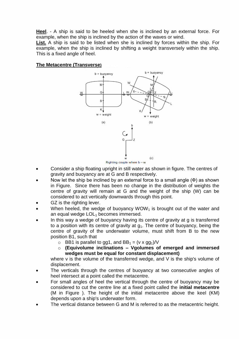
Heel. - A ship is said to be heeled when she is inclined by an external force. For example, when the ship is inclined by the action of the waves or wind. List. A ship is said to be listed when she is inclined by forces within the ship. For example, when the ship is inclined by shifting a weight transversely within the ship. This is a fixed angle of heel. The Metacentre (Transverse)
Consider a ship floating upright in still water as shown in figure. The centres of
gravity and buoyancy are at G and B respectively.
Now let the ship be inclined by an external force to a small angle (Ф) as shown in Figure. Since there has been no change in the distribution of weights the centre of gravity will remain at G and the weight of the ship (W) can be considered to act vertically downwards through this point.
GZ is the righting lever.
When heeled, the wedge of buoyancy WOW1 is brought out of the water and an equal wedge LOL1 becomes immersed.
In this way a wedge of buoyancy having its centre of gravity at g is transferred to a position with its centre of gravity at g1. The centre of buoyancy, being the centre of gravity of the underwater volume, must shift from B to the new position B1, such that
o BB1 is parallel to gg1, and BB1 = (v x gg1)/V o (Equivolume inclinations – Vgolumes of emerged and immersed
wedges must be equal for constant displacement) where v is the volume of the transferred wedge, and V is the ship's volume of displacement.
The verticals through the centres of buoyancy at two consecutive angles of heel intersect at a point called the metacentre.
For small angles of heel the vertical through the centre of buoyancy may be considered to cut the centre line at a fixed point called the initial metacentre (M in Figure ). The height of the initial metacentre above the keel (KM) depends upon a ship's underwater form.
The vertical distance between G and M is referred to as the metacentric height.
o If G is below M the ship is said to have positive metacentric height o if G is above M the metacentric height is said to be negative.
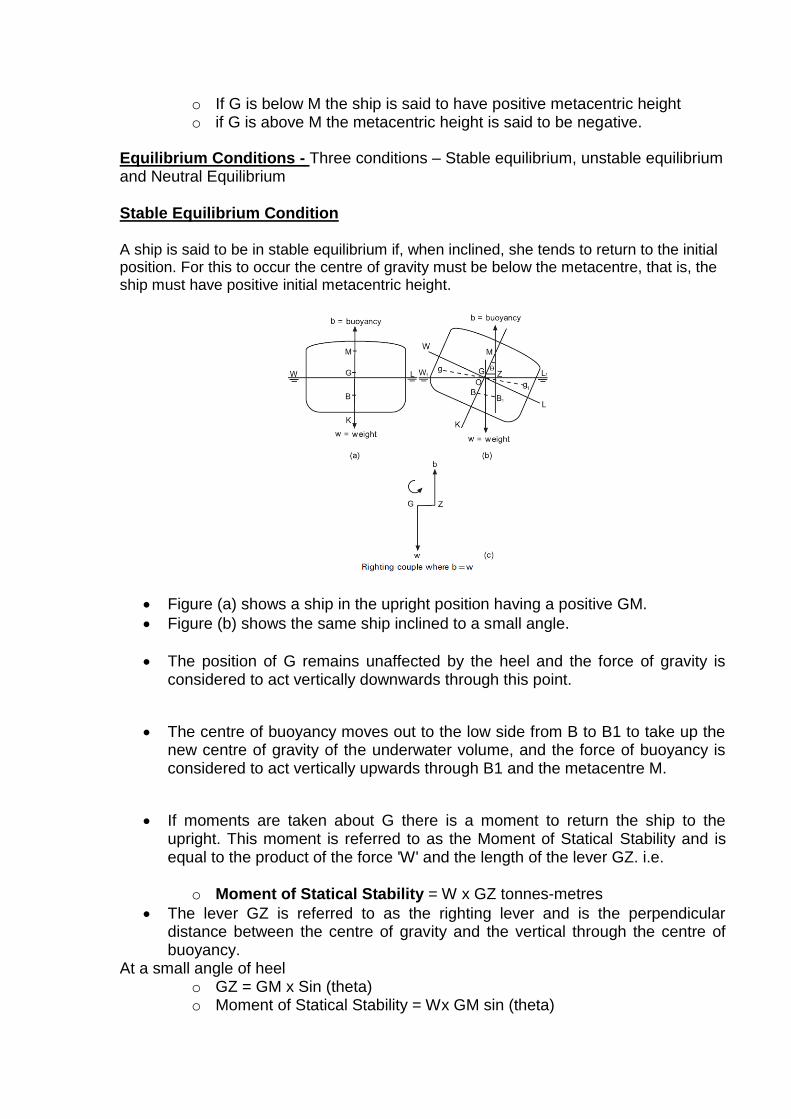
Equilibrium Conditions - Three conditions – Stable equilibrium, unstable equilibrium and Neutral Equilibrium Stable Equilibrium Condition A ship is said to be in stable equilibrium if, when inclined, she tends to return to the initial position. For this to occur the centre of gravity must be below the metacentre, that is, the ship must have positive initial metacentric height.
Figure (a) shows a ship in the upright position having a positive GM.
Figure (b) shows the same ship inclined to a small angle.
The position of G remains unaffected by the heel and the force of gravity is considered to act vertically downwards through this point.
The centre of buoyancy moves out to the low side from B to B1 to take up the new centre of gravity of the underwater volume, and the force of buoyancy is considered to act vertically upwards through B1 and the metacentre M.
If moments are taken about G there is a moment to return the ship to the upright. This moment is referred to as the Moment of Statical Stability and is equal to the product of the force 'W' and the length of the lever GZ. i.e.
o Moment of Statical Stability = W x GZ tonnes-metres
The lever GZ is referred to as the righting lever and is the perpendicular distance between the centre of gravity and the vertical through the centre of buoyancy.
At a small angle of heel o GZ = GM x Sin (theta) o Moment of Statical Stability = Wx GM sin (theta)
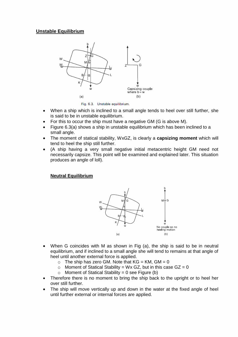
Unstable Equilibrium
When a ship which is inclined to a small angle tends to heel over still further, she
is said to be in unstable equilibrium.
For this to occur the ship must have a negative GM (G is above M).
Figure 6.3(a) shows a ship in unstable equilibrium which has been inclined to a small angle.
The moment of statical stability, WxGZ, is clearly a capsizing moment which will tend to heel the ship still further.
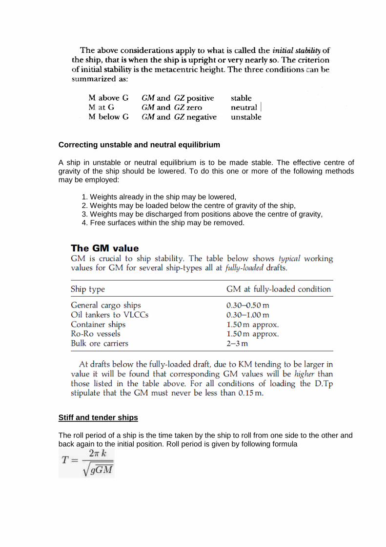
(A ship having a very small negative initial metacentric height GM need not necessarily capsize. This point will be examined and explained later. This situation produces an angle of loll). Neutral Equilibrium
When G coincides with M as shown in Fig (a), the ship is said to be in neutral equilibrium, and if inclined to a small angle she will tend to remains at that angle of heel until another external force is applied.
o The ship has zero GM. Note that KG = KM, GM = 0 o Moment of Statical Stability = Wx GZ, but in this case GZ = 0 o Moment of Statical Stability = 0 see Figure (b)
Therefore there is no moment to bring the ship back to the upright or to heel her over still further.
The ship will move vertically up and down in the water at the fixed angle of heel until further external or internal forces are applied.
Correcting unstable and neutral equilibrium A ship in unstable or neutral equilibrium is to be made stable. The effective centre of gravity of the ship should be lowered. To do this one or more of the following methods may be employed:
1. Weights already in the ship may be lowered, 2. Weights may be loaded below the centre of gravity of the ship, 3. Weights may be discharged from positions above the centre of gravity, 4. Free surfaces within the ship may be removed.
Stiff and tender ships The roll period of a ship is the time taken by the ship to roll from one side to the other and back again to the initial position. Roll period is given by following formula

Stiff Ship. When a ship has a comparatively large GM, for example 2m to 3m, the righting moments at small angles of heel will also be comparatively large. It will thus require larger moments to incline the ship. When inclined she will tend to return more quickly to the initial position. The result is that the ship will have a comparatively short time period, and will roll quickly (and perhaps violently) from side to side. A ship in this condition is said to be `stiff', and such a condition is not desirable. The time period could be as low as 8 seconds. The effective centre of gravity of the ship should be raised within that ship toreduce GM. Tender Ships. When the GM is comparatively small, for example 0.16m to 0.20m the righting moments at small angles of heel will also be small. The ship will thus be much easier to incline and will not tend to return so quickly to the initial position. The time period will be comparatively long and a ship, for example 30 to 35 seconds, in this condition is said to be `tender'. As before, this condition is not desirable and steps should be taken to increase the GM by lowering the effective centre of gravity of the ship. The officer responsible for loading a ship should aim at a happy medium between these two conditions whereby the ship is neither too stiff nor too tender. A time period of 20 to 25 seconds would generally be acceptable for those on board a ship at sea. Negative GM and angle of loll It has been shown previously that a ship having a negative initial metacentric height will be unstable when inclined to a small angle. This is shown in Figure 6.5(a).
As the angle of heel increases, the centre of buoyancy will move out still further to the low side. If the centre of buoyancy moves out to a position vertically under G, the capsizing moment will have disappeared as shown in (b). The angle of heel at which this occurs is called the angle of loll. It will be noticed that at the angle of loll, the GZ is zero. G remains on the centre line. If the ship is heeled beyond the angle of loll from y1 to y2, the centre of buoyancy will move out still further to the low side and there will be a moment to return her to the angle of loll as shown in Figure 6.5(c).
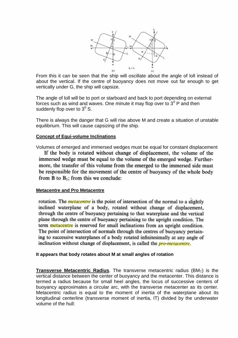
From this it can be seen that the ship will oscillate about the angle of loll instead of about the vertical. If the centre of buoyancy does not move out far enough to get vertically under G, the ship will capsize. The angle of loll will be to port or starboard and back to port depending on external forces such as wind and waves. One minute it may flop over to 30 P and then suddenly flop over to 30 S. There is always the danger that G will rise above M and create a situation of unstable equilibrium. This will cause capsizing of the ship. Concept of Equi-volume Inclinations
Volumes of emerged and immersed wedges must be equal for constant displacement
Metacentre and Pro Metacentre
It appears that body rotates about M at small angles of rotation
Transverse Metacentric Radius. The transverse metacentric radius (BMT) is the vertical distance between the center of buoyancy and the metacenter. This distance is termed a radius because for small heel angles, the locus of successive centers of buoyancy approximates a circular arc, with the transverse metacenter as its center. Metacentric radius is equal to the moment of inertia of the waterplane about its longitudinal centerline (transverse moment of inertia, IT) divided by the underwater volume of the hull:
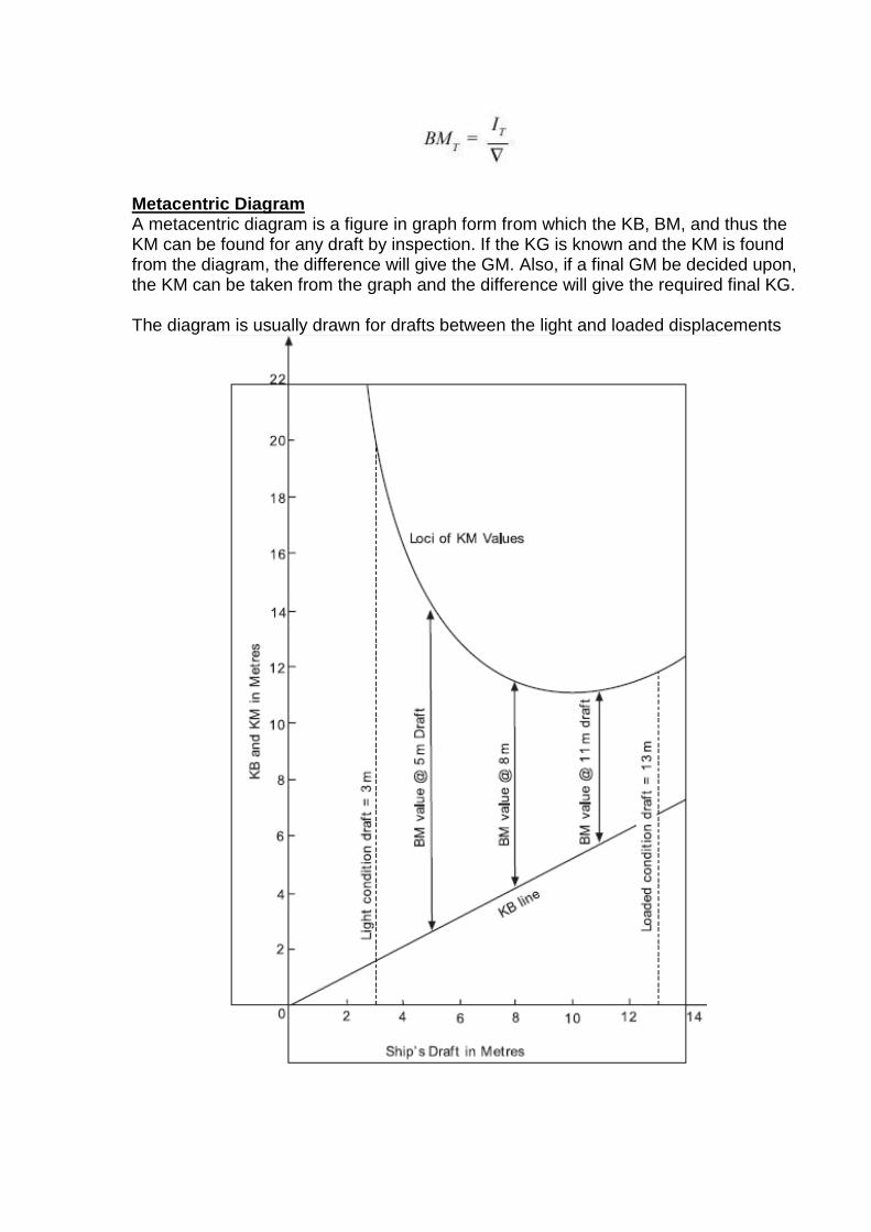
Metacentric Diagram A metacentric diagram is a figure in graph form from which the KB, BM, and thus the KM can be found for any draft by inspection. If the KG is known and the KM is found from the diagram, the difference will give the GM. Also, if a final GM be decided upon, the KM can be taken from the graph and the difference will give the required final KG. The diagram is usually drawn for drafts between the light and loaded displacements
BM Diagram
Metacentric Curve
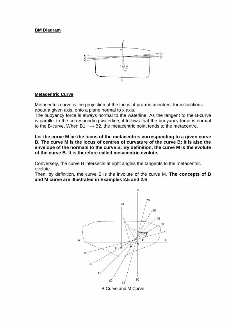
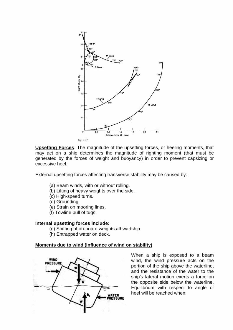
Metacentric curve is the projection of the locus of pro-metacentres, for inclinations about a given axis, onto a plane normal to x axis. The buoyancy force is always normal to the waterline. As the tangent to the B-curve is parallel to the corresponding waterline, it follows that the buoyancy force is normal to the B-curve. When B1 −→ B2, the metacentric point tends to the metacentre. Let the curve M be the locus of the metacentres corresponding to a given curve B. The curve M is the locus of centres of curvature of the curve B; it is also the envelope of the normals to the curve B. By definition, the curve M is the evolute of the curve B. It is therefore called metacentric evolute. Conversely, the curve B intersects at right angles the tangents to the metacentric evolute. Then, by definition, the curve B is the involute of the curve M. The concepts of B and M curve are illustrated in Examples 2.5 and 2.6
B Curve and M Curve
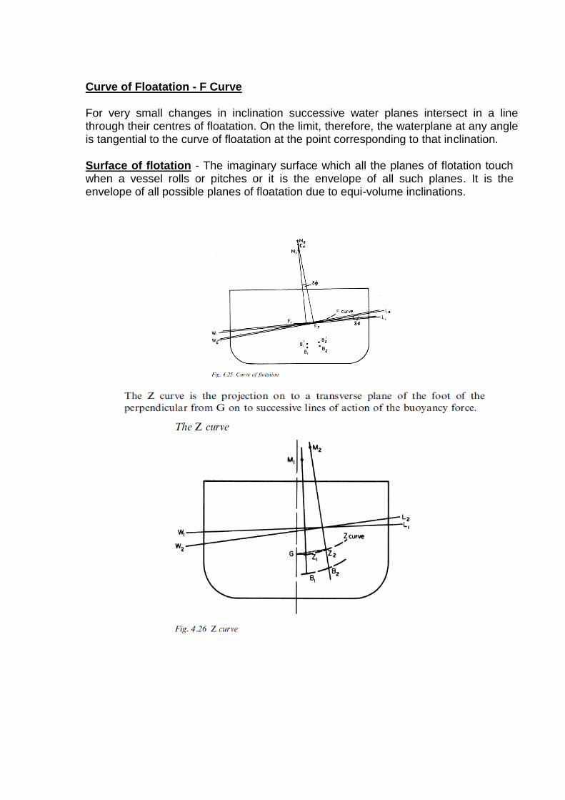
Curve of Floatation - F Curve For very small changes in inclination successive water planes intersect in a line through their centres of floatation. On the limit, therefore, the waterplane at any angle is tangential to the curve of floatation at the point corresponding to that inclination. Surface of flotation - The imaginary surface which all the planes of flotation touch when a vessel rolls or pitches or it is the envelope of all such planes. It is the envelope of all possible planes of floatation due to equi-volume inclinations.
Upsetting Forces. The magnitude of the upsetting forces, or heeling moments, that may act on a ship determines the magnitude of righting moment (that must be generated by the forces of weight and buoyancy) in order to prevent capsizing or excessive heel. External upsetting forces affecting transverse stability may be caused by:
(a) Beam winds, with or without rolling. (b) Lifting of heavy weights over the side. (c) High-speed turns. (d) Grounding. (e) Strain on mooring lines. (f) Towline pull of tugs.
Internal upsetting forces include:
(g) Shifting of on-board weights athwartship. (h) Entrapped water on deck.
Moments due to wind (Influence of wind on stability)
When a ship is exposed to a beam wind, the wind pressure acts on the portion of the ship above the waterline, and the resistance of the water to the ship's lateral motion exerts a force on the opposite side below the waterline. Equilibrium with respect to angle of heel will be reached when:
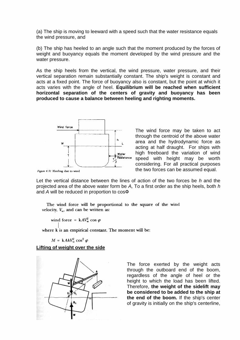
(a) The ship is moving to leeward with a speed such that the water resistance equals the wind pressure, and (b) The ship has heeled to an angle such that the moment produced by the forces of weight and buoyancy equals the moment developed by the wind pressure and the water pressure. As the ship heels from the vertical, the wind pressure, water pressure, and their vertical separation remain substantially constant. The ship's weight is constant and acts at a fixed point. The force of buoyancy also is constant, but the point at which it acts varies with the angle of heel. Equilibrium will be reached when sufficient horizontal separation of the centers of gravity and buoyancy has been produced to cause a balance between heeling and righting moments.
The wind force may be taken to act through the centroid of the above water area and the hydrodynamic force as acting at half draught. For ships with high freeboard the variation of wind speed with height may be worth considering. For all practical purposes the two forces can be assumed equal.
Let the vertical distance between the lines of action of the two forces be h and the projected area of the above water form be A, To a first order as the ship heels, both h and A will be reduced in proportion to cosФ
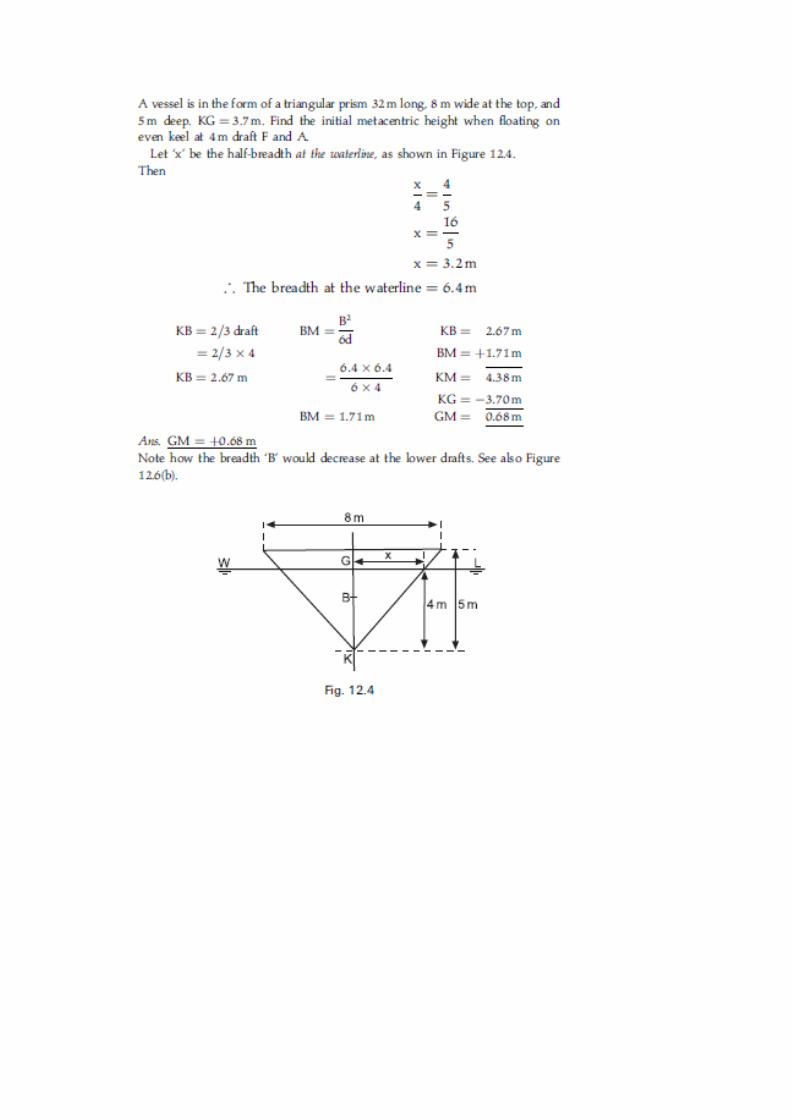
Lifting of weight over the side
The force exerted by the weight acts through the outboard end of the boom, regardless of the angle of heel or the height to which the load has been lifted. Therefore, the weight of the sidelift may be considered to be added to the ship at the end of the boom. If the ship's center of gravity is initially on the ship's centerline,

as at G, the center of gravity of the combined weight of the ship and the sidelift will be located along the line GA, and will move to a final position, G1, when the load has been lifted clear of the pier. Point G1 will be off the ship's centerline and somewhat higher than G. The ship will heel until the center of buoyancy has moved off the ship's centerline to a position directly below point G1.
Movement of weights already aboard the ship (such as passengers, liquids or cargo) will cause the ship's center of gravity to move. If a weight is moved from A to B, the ship's center of gravity will move from G to G1 in a direction parallel to the direction of movement of the shifted weight. The ship will heel until the center of
buoyancy is directly below point G1.Passengers, liquids or cargo, will cause the ship's center of gravity to move. If a weight is moved from A to B, the ship's center of gravity will move from G to G1 in a direction parallel to the direction of movement of the shifted weight. The ship will heel until the center of buoyancy is directly below point G1
Ship when executing a turn.
When a ship is executing a turn, a centrifugal force is generated, which acts horizontally through the ship's center of gravity. This force is balanced by a horizontal water pressure on the side of the ship. Except for the point of application of
the heeling force, the situation is similar to that in which the ship is acted upon by a beam wind, and the ship will heel until the moment of the ship's weight and buoyancy equals that of the centrifugal force and water pressure. Grounding of ships.
If a ship runs aground in such a manner that the bottom offers little restraint to heeling the reaction of the bottom may produce a heeling moment. As the ship grounds, part of the energy due to its forward motion may be absorbed in lifting the ship, in which case a reaction, R, between the bottom and the ship would develop.

This reaction may be increased later as the tide ebbs. Under these conditions, the force of buoyancy would be less than the weight of the ship, since the ship would be supported by the combination of buoyancy and the reaction of the bottom. The ship would heel until the moment of buoyancy about the point of contact with the bottom became equal to the moment of the ship's weight about the same point,
when (W — R) x a equals W x b. Strain on Mooring line
A moored ship may be heeled by the combination of strain on the mooring lines and pressure produced by wind or current.
Tow line pulls
Tow line strain may produce heeling moments in either the towed or towing ship
Non Symmetrical Accumulation of ice
Non symmetrical accumulation of ice can cause heeling of ship.
Once ice has started to form, it will continue to accumulate under unfavorable conditions and the only recourse is to institute ice-removal measures or leave the area.
High winds are likely to occur during periods of icing and it is appropriate to consider combined icing and wind effects
There is reduction in max permitted wind velocity
For smaller ships, topside icing results in a more significant reduction in righting arms and the allowable beam-wind velocity is accordingly less. For
Danger of Capsizing. In any of the foregoing examples
it is possible that equilibrium would not be reached before the ship capsized.
It is also possible that equilibrium would not be reached until the angle of heel became so large that water would be shipped through topside openings, and that the weight of this water, running to the low side of the ship, would contribute to capsizing which otherwise would not have occurred.
Effect of Superstructure on Stability (figure)
Heavy Superstructure can shift G higher – adverse effect on stability (decreases the metacentric height)
Lighter materials is beneficial.
Enclosed/ watertight superstructure can add to the reserve of buoyancy.
Uniform watertight superstructure effectively increases the freeboard.
If superstructure is not uniform, there will be considerable shift in ‘B’ when superstructure enters water.

Example 1 A box-shaped vessel is 24m x 5m x5m and floats on an even keel at 2m draft. KG = 1.5 m. Calculate the initial metacentric height. KB = 0.5 x draft = 1.0 m BM = B2/12d = 1.04 m, KB =1.00m, BM .=1.04m, KM = 2.04m, GM = 0.54m Example 2
Example 3

Submerged Equilibrium. A fully submerged body (submarine) presents a special case.
Firstly there is no waterplane and therefore no metacentre. The forces of weight and displacement will always act vertically through G and B respectively.
In the case of a submerged submarine, the center of buoyancy is fixed,
A given upsetting moment produces very nearly the same inclination in the longitudinal direction as it does in the transverse direction. The only difference, which is trivial, is due to the effect of liquids aboard which may move to a different extent in the two directions.
Stability then will be the same for inclination about any axis. It will be positive if B is above G.
A submerged submarine, however, is comparatively free from large upsetting forces. Shifting of the center of gravity as the result of weight changes is carefully avoided. For example, when a torpedo is fired, its weight is immediately replaced by an equal weight of water at the same location.

Before a submarine is submerged, considerable effort has been expended, both in design and operation, to ensure that:
(a) Neutral Buoyancy - The weight of the submarine, with its loads and ballast, will be very nearly equal to the weight of the water it will displace when submerged.
(b) Zero trim. The center of gravity of these weights will be very nearly in the same logitudinal position as the center of buoyancy of the submerged submarine.
(c) Positive stability. The center of gravity of these weights will be lower than the center of buoyancy of the submerged submarine.
Submarine on the surface, with weights adjusted so that the first two conditions will be satisfied upon filling the main ballast tanks, is said to be in diving trim. The effect of this situation is that the submarine, in so far as transverse and longitudinal stability are concerned, acts in the same manner as a pendulum. This imaginary pendulum is supported at the center of buoyancy, has a length equal to the separation of the centers of buoyancy and gravity, and a weight equal to the weight of the submarine. It is not practical to achieve an exact balance of weight and buoyancy, or to bring the center of gravity precisely to the same longitudinal position as the center of buoyancy. It is also not necessary, since minor deviations can be counteracted by the effect of the bow and stern planes when underway submerged