stability guide - fiskeriets arbejdsmiljøråd – endnu ... · stability guide for smaller vessels...
TRANSCRIPT
STABILITY GUIDE FOR SMALLER VESSELS
The EU’s Fisheries Fund
Ministry of Food, Agriculture and Fisheries
The project is funded by the Ministry of Food, Agriculture and Fisheries and the EU

2
All photos and texts in this publication are protected by Danish copyright law. All rights belong to or are managed by the Danish Fishermen’s Occupational Health Service. It is not allowed
to copy or use texts and pictures from this publication without written permission.
3Preface
Over the years, a number of vessels in the category 0 - 15 metres have capsized or sunk. Several of these losses were due to vessel instability.
A number of fishermen have lost their lives because of this.
Failure in stability can be the result of repeated rebuilding of a vessel, where a number of small changes suddenly has a great impact on stability. It may also be due to changes in fishing patterns as well as fishing in other waters where external influences are different.
So it is important that the captain has a good knowledge of the vessel’s stability and a thorough understanding of how it can change during fishing and in connection with rig-ging to another kind of fishery. In particular when rebuilding or making other changes to the vessel, it is extremely important to be aware of the impact this has on the stability of the vessel.
This reference book illustrates the basic principles of stability and how to calculate stabil-ity. It is a guide to understanding and interpreting vessel stability calculations. Stability problems are highlighted in the form of case studies with examples of both improving and deteriorating changes in stability.
The main intention is for this publication to be instrumental in reducing the death toll as-sociated with these accidents.
We also expect that the material will help to reduce dangerous situations related to stabil-ity issues.
It is important that both fishermen and service companies who work on vessels help to increase safety in the fishing sector and thereby prevent sinking, where lack of stability is a contributing factor.
We hope this guide will give you a greater knowledge and understanding of what stability is and make you more aware of how important it is in your daily work
We hope you enjoy reading this booklet!
Flemming Christensen Danish Fishermen’s Occupational Health Service

4
Chapter 1: What is stability? 5
Lightweight, deadweight and displacement 5Buoyancy 6Centre of gravity G 7Centre of buoyancy B 7The centre of buoyancy B moves when the vessel heels 8Metacentric height GM 8Righting arm GZ 9GZ curve 10
Chapter 2: Determining a vessel’s stability 12
Line Drawing 12Preparations for the heeling test 13Carrying out the heeling test 13Additional data collection under the heeling test 15Calculation of the vessel’s lightweight and centre of gravity 16Calculating the vessel stability 20What are the rules? 21What can the stability report be used for? 22Dynamometer Test 26What about the very small vessels with a scantling number under 20? 27
Chapter 3: Measures to improve stability 30
Measures to improve stability 30Freeboard 31Weight critical review of the vessel 32Buoyancy Cases / side building on the side of the wheelhouse aft 32Buoyancy Cases / side building on the side of the wheelhouse in front 33Added buoyancy in the gunwale 33Raised deck 33Shelter deck 34Closing the pond 35Installation of ballast 35Extension amidships prior to the installation of ballast 35Rebuilding the stern 35Net trunk 36Tackle box 36Roll damping tank and bilge keels do not improve stability 37New heeling test 37
Chapter 4: What influences stability 38
Is the vessel watertight? 38Are you sailing with free surfaces? 40Heel 41Leech trim 42Hauling fish / lifting 43Towing with gear 44Dirty nets on deck 45Icing 46Heavy sea 47Small changes over time 48Routine check 49Convergence of several factors 50
Terms and abbreviations 51
Contents

5Chapter 1
What is stability?Stability is a measure of the vessel’s ability to get back on an even keel after having suf-fered a heel.
Different factors affect a vessel’s stability.
Basically it is the ratio between the centre of gravity and the distribution of a vessel’s buoyancy that determines the vessel’s abil-ity to get back on an even keel.
Lightweight, deadweight and displacementThe vessel’s own weight and the distribution of the weights on the vessel are essential for determining the vessel’s stability.
The vessel’s weight is composed as follows:
Lightweight
This is the weight of the unrigged vessel without gear, fuel oil, water, ice, boxes, crew, provisions, catch, etc.
Lightweight changes e.g. when the ves-sel is fitted with optional equipment, when switching engines, winches or other fixed components.
Deadweight
This is the term for all the weights the crew takes on board in order to fish or during fishing. Deadweight includes equipment, fuel oil, water, ice, boxes, crew, provisions, catch, etc.
Stablilty ... ?
Centre of gravity ...
Freeboard ...
How was that again ???
6 Chapter 1
Displacement
Displacement is the term for the vessel’s total weight. That means displacement = lightweight + deadweight.
During fishing, the vessel’s displacement changes constantly as a result of oil con-sumption and the weight of the fish caught.
A fishing vessel has a tonnage certificate that displays a certain tonnage.
This tonnage has nothing to do with the vessel’s weight.
The tonnage on the tonnage certificate is an expression of the vessel’s volume.
The tonnage has therefore nothing to do with the vessel’s stability.
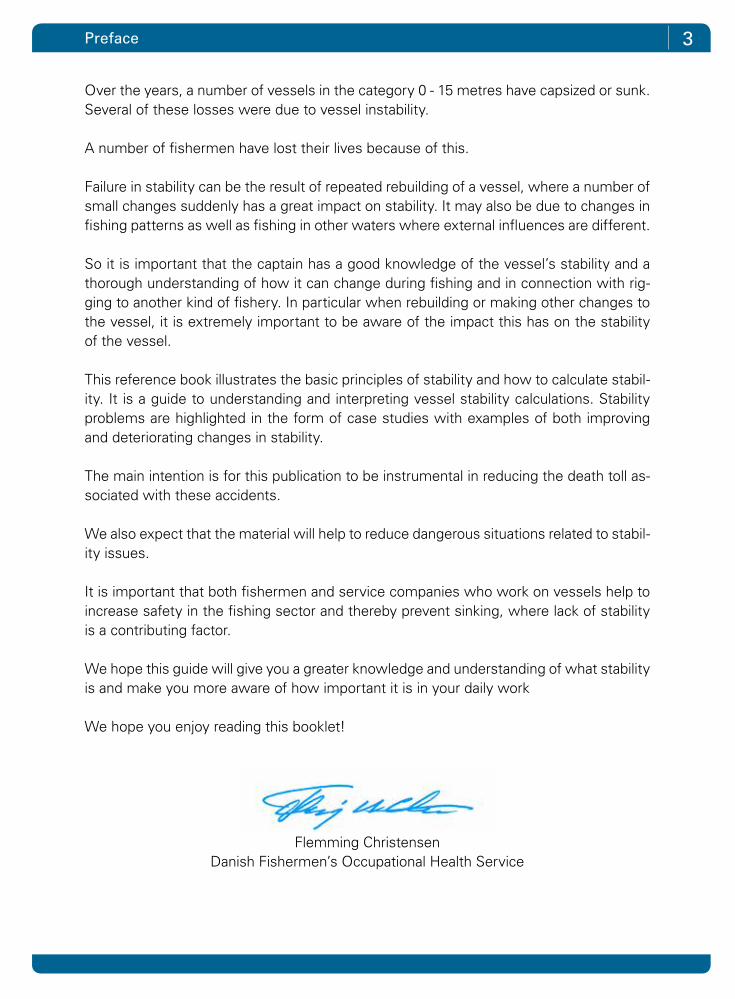
BuoyancyA vessel floating on the water will displace an amount of water equal to the weight of the vessel (displacement).
This is illustrated by the figure to the right:
1. A large container filled with water up to an overflow.
2. A vessel with a weight of 10 tonnes is lowered into the tank.
3. Exactly 10 tonnes of water flow over the edge.
The experiment can be extended, for ex-ample by loading a vessel with 2 tonnes of fish, as illustrated in the figure to the left.
The vessel is thus 2 tonnes heavier and pushed deeper into the water.
An additional 2 tonnes of water flow out of the big container, so that now the small container alongside it contains 12 tonnes of water, equal to the combined weight of the vessel and the fish.

7What is stability?
Centre of gravity GThe centre of gravity is a rather theoretical concept. It is composed of all weights on board, including the vessel’s own weight (lightweight).
For example, if the total weight of the vessel (displace-ment), including deadweight such as gear, catch, etc. is 10 tonnes, all the small weights can be replaced by one total weight of 10 tonnes located in the centre of gravity. One can say that the centre of gravity is the average location of all the weights.
• For most fishing vessels, the centre of gravity is usually just above the waterline.
• Vessels may become unstable if the centre of grav-ity is positioned too high.
• Fish and gear on deck pull the centre of gravity up.• Installation of new equipment on deck or in the wheelhouse pulls the centre of
gravity up.• Replacement of a heavy diesel engine with a lighter engine pulls the centre of
gravity up.• A high centre of gravity makes the vessel roll more slowly and can be a danger
signal.
Centre of buoyancy BAll parts of the hull under the waterline contribute to the vessel’s overall buoyancy. The total buoyancy can, just like the centre of gravity mentioned above, be merged in one single point called the centre of buoyancy and this is indi-cated by the letter B.
The centre of buoyancy B is the average location of the total buoyancy.
B is not fixed; it changes all the time depending on the vessel’s draft, heel and trim.

8 Chapter 1
The centre of buoyancy B moves when the vessel heels When the vessel is upright, and not tilted, the centre of gravity G is in the vessel’s centre line.
In a straight line below is the centre of buoyancy B, and the vessel is in balance.
If the vessel is heeled, the buoyancy centre moves imme-diately off to the side of the vessel. See the adjacent illus-tration, where B is moved to one side and called B1.
If the gear and catch are stowed away safely, there is no weight on board that can move during the roll. So the centre of gravity G remains in the same position.
Metacentric height GMUnder a light small heeling, the vertical line of buoyancy intersects with the vessel’s centre line at a point called meta centre, which is indicated by the letter M.
The distance between the centre of gravity G and meta centre M is called the metacentric height GM.
The GM value is a measure of the vessel’s stability under small heeling, also called initial stability.
The higher the GM value, the better the vessel’s initial stability and the harder it is to get the vessel to heel.
A vessel with a large GM value can be described as a rigid vessel that rolls fast on sea.

9What is stability?
Righting arm GZWhen the vessel suffers a heel, the centre of gravity G and the centre of buoyancy B are no longer on the same vertical line above one another.
The vessel is brought out of balance.
As the figure shows, there is a distance be-tween the vertical line that expresses the vessel’s weight through the centre of grav-ity G and the vertical line that expresses the vessel buoyancy through the current centre of buoyancy B1.
The horizontal distance between the two lines is called the righting arm GZ - and the size of the righting arm GZ is crucial to whether the vessel can straighten up and get back on an even keel. The greater the righting arm is, the better is the ability of the vessel to get back on an even keel.
The figure to the right shows how the crew can influence the size of the righting arm depending on how the vessel is loaded.
The deeper the weight is placed in the ves-sel, the further down is the centre of grav-ity G. Thus the righting arm GZ is larger. (See point G1)
Conversely, GZ is smaller if the weights are placed high up in the vessel, so that the centre of gravity G moves higher up in the vessel. (See point G2)
10 Chapter 1
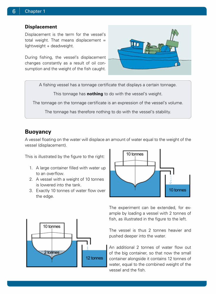
GZ curveWhen the vessel heels, the part of the vessel that is under water changes behaviour. This means that the centre of buoyancy B keeps changing, depending on the heel of the vessel. The GZ value changes alongside with the heeling.
The illustration below shows how the GZ value increases, the more the vessel heels. At some point the GZ value reaches a maximum. Here the vessel has the maximum righting force. After this point the GZ value decreases. When the GZ value drops to 0, the vessel capsizes.
GZ values at different degrees of heeling can be plotted to form a curve as shown below - called a GZ curve.
GZ curves give a quick impression of the vessel and its stability. Different types of ves-sels have different GZ curves.
heeling

11What is stability?
The illustration below shows 3 GZ curves for 3 different types of vessels.
Curve 1 is for a traditional deck vessel. The curve peaks at approx. 25 degrees and ex-tends to approx. 70 degrees.
Curve 2 is a wide flat-bottomed vessel. The curve is initially steeper than curve 1. This means that the vessel is more rigid - it has a big GM and is difficult to get to heel, but the steep curve can also be an indica-tion that the vessel rolls faster. The vessel already reaches the maximum righting arm at a slight heel. A characteristic of these vessels is that the righting arm drops fast
and the vessel cannot heel as much as a traditional deck vessel.
Curve 3 shows a vessel with completely different properties. The curve starts flatter. The initial stability is relatively low. The vessel heels easily, but it rolls more slowly. As the curve grows, it becomes increasingly difficult to get the vessel to heel over further. A vessel with such a curve is typically a shelter deck vessel, where the closed shelter contributes to the buoyancy and increases the vessel’s freeboard considerably. A large freeboard will improve the extent of the GZ curve.
heeling
12
Determining a vessel’s stabilityIn order to determine a vessel’s stability, a heeling test has to be carried out in which the vessel’s centre of gravity is determined.
A heeling test has to be conducted by a marine engineer who is authorized by the Danish Maritime Authority.
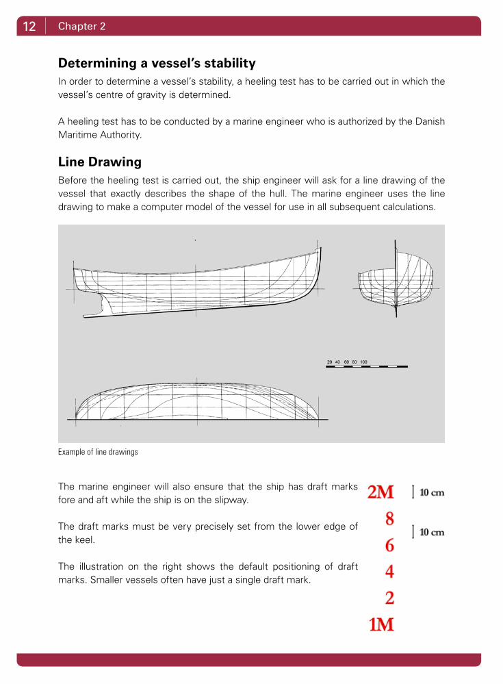
Line DrawingBefore the heeling test is carried out, the ship engineer will ask for a line drawing of the vessel that exactly describes the shape of the hull. The marine engineer uses the line drawing to make a computer model of the vessel for use in all subsequent calculations.
The marine engineer will also ensure that the ship has draft marks fore and aft while the ship is on the slipway.
The draft marks must be very precisely set from the lower edge of the keel.
The illustration on the right shows the default positioning of draft marks. Smaller vessels often have just a single draft mark.
Chapter 2
Example of line drawings
13
Preparations for the heeling testBefore carrying out the heeling test, the skipper is asked to get the vessel ready . This means:
1. Fill up the tanks (Alternatively: empty one or more tanks)2. Ensure that the tanks are closed3. Make sure that the vessel is not listing4. Bilge cargo and ground water5. Unload from the cargo any excess ice6. Unload ship equipment, or else obtain the weights of the gear that is on board
during the test7. Bring the equipment that belongs to the vessel onboard8. Tidy up and provide an overview of what other weights there are on board9. Help to get the heel weights brought on board10. Obtain a boat or barge for use in the reading of the draft marks11. Position the vessel at a quiet quayside with sufficient water depth, where the
vessel lies in the direction of the wind
These measures should ensure that the test can be carried out as accurately as possible.
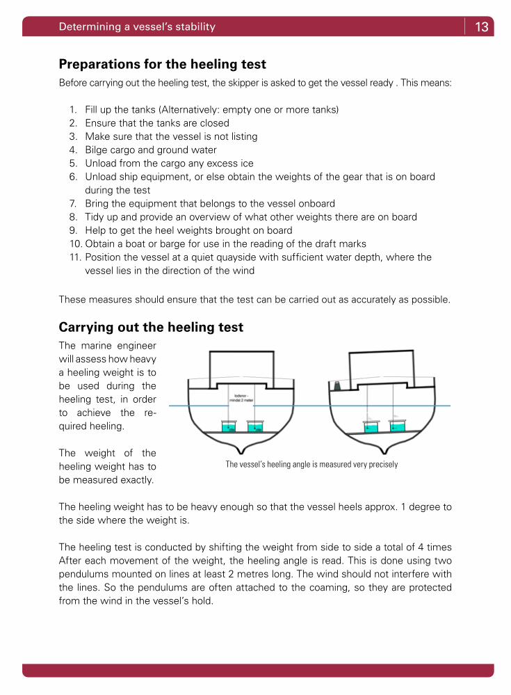
Carrying out the heeling testThe marine engineer will assess how heavy a heeling weight is to be used during the heeling test, in order to achieve the re-quired heeling.
The weight of the heeling weight has to be measured exactly.
The heeling weight has to be heavy enough so that the vessel heels approx. 1 degree to the side where the weight is.
The heeling test is conducted by shifting the weight from side to side a total of 4 times After each movement of the weight, the heeling angle is read. This is done using two pendulums mounted on lines at least 2 metres long. The wind should not interfere with the lines. So the pendulums are often attached to the coaming, so they are protected from the wind in the vessel’s hold.
Determining a vessel’s stability
The vessel’s heeling angle is measured very precisely
14 Chapter 2
The two pendulums are suspended in an oil bath in order to curb their movements. By measuring the lengths of the lines and the movements of the pendulums to the side to which the heel weight is moved, the heel of the vessel can be measured relatively ac-curately.
As the two pendulums are mounted on lines at least 2 metres long, they act as fairly precise protractors.
When the test is run, it is important that no other weights on the vessel are moved.
So the only people on board are those that carry out the tests. Each person on board must be in exactly the same place when the weights are read.
Other conditions that can interfere with the test and cause errors in the results are:
1. Free surfaces in tanks (it is very important that the tanks are completely full)2. Bilge water can run transversely3. Confluence between the tanks4. Wind, waves and currents5. Contact with berth6. Ground contact7. Churned water from other ships in the harbour8. Persons onboard moving from their positions
The heeling weight is moved a total of 4 times from side to side. At each movement the distance is measured.
In principle, it is enough to move the weight once and read the change in the heel. Re-peating the measurements 4 times and reading the heel of two independent pendulums makes sure that the results are correct, thereby eliminating errors.

15Determining a vessel’s stability
Additional data collection under the heeling testThe heeling test is not over until the following things are checked:
1. Draft of water is determined by reading the distance from the vessel’s draft mark down to the water surface from a barge or boat
2. Determining the water density (the more salt there is in the water, the higher the vessel lies in the water)
3. Review of the vessel for registration and measurement of redundant and missing weights.
a. Excess weight is the weight on board that is not included in the ship’s own weight (lightweight):
I Fishing gear
II Fuel oil and fresh water
III Heel weights
IV Persons
V Craftsman tools and stores
VI Fish boxes and ice
b. Missing weights are all the weights that are a part of the ship’s weight (lightweight):
I Hydraulic oil in pipesystem
II Engine room equipment
III Deck equipment
IV Lifesaving equipment
V Accommodation materials
VI Ballast, limited amount
By talking to the skipper, the marine engi-neer will collect data on how the vessel is used, so the calculations can reflect and highlight the vessel’s stability under differ-ent conditions.
For example, how much fish and tackle the vessel is permitted to carry on deck when the load is empty.
Measurement of draft
16 Chapter 2
Calculation of the vessel’s lightweight and centre of gravityAfter the heeling test, the marine engineer calculates the vessel’s stability back at his of-fice.
The vessel’s lightweight is calculated first.
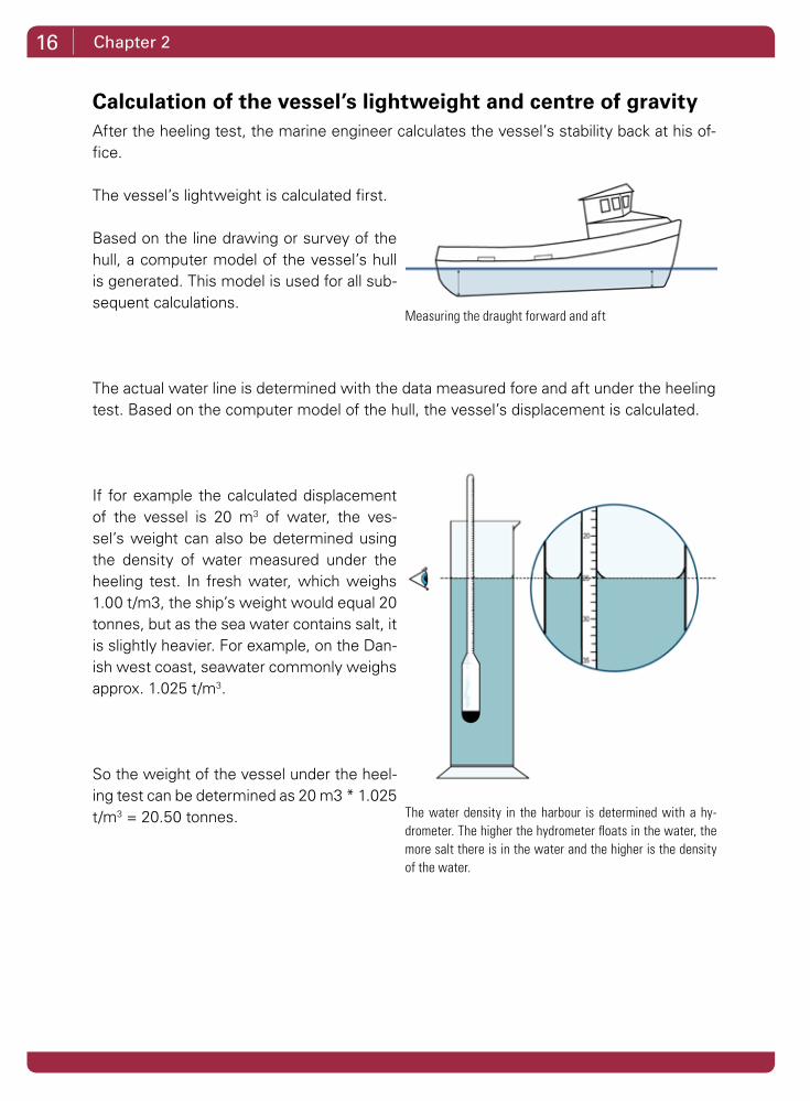
Based on the line drawing or survey of the hull, a computer model of the vessel’s hull is generated. This model is used for all sub-sequent calculations.
The actual water line is determined with the data measured fore and aft under the heeling test. Based on the computer model of the hull, the vessel’s displacement is calculated.
If for example the calculated displacement of the vessel is 20 m3 of water, the ves-sel’s weight can also be determined using the density of water measured under the heeling test. In fresh water, which weighs 1.00 t/m3, the ship’s weight would equal 20 tonnes, but as the sea water contains salt, it is slightly heavier. For example, on the Dan-ish west coast, seawater commonly weighs approx. 1.025 t/m3.
So the weight of the vessel under the heel-ing test can be determined as 20 m3 * 1.025 t/m3 = 20.50 tonnes. The water density in the harbour is determined with a hy-
drometer. The higher the hydrometer floats in the water, the more salt there is in the water and the higher is the density of the water.
Measuring the draught forward and aft

17Determining a vessel’s stability
Under the heeling test the following data was measured:
a = Distance of the heel weight moved transversely, measured in metres w = Weight of the heel weight, measured in tonnes W = The vessel’s weight in tonnes L = Length of the 2 lines including the pendulums V = Transverse movement of the pendulum
This data is used to calculate the Metacentric height (GM) of the vessel. This is the first step in calculating the vessel’s centre of gravity G.
Example: a = The heel weight moved 3 metres transversely w = The heel weight weighs 200 kg W = The vessel’s weight was 20.50 tonnes under the heel test L = The length of the lines including pendulum is 2,200 mm V = The transverse movement of the pendulum is 80 mm
The Metacenter M for a given water line is determined by the shape of the hull below the waterline. The marine engineer can calculate the Metacentre M from the model of the hull.
The value is read from a hydrostatic print such as KMT:
Version of Hydrostatic Particulars: krpro
TRIM ON BASE LINE -0.247 m SPECIFIC GRAVITY 1.025 t/m3 CODE OF ORIGIN AP KEEL THICKNESS 240 mm TRIM UNDER KEEL 0.670 m RISE OF KEEL 0.917 m
HYDROSTATIC PARTICULARS
D/BASE DEXT DISPLT TPCM MCT/CM LCB LCF KMT KML KB (m) (m) (t) (t) (t.m) (m) (m) (m) (m) (m)
1.410 1.650 20.50 0.28 0.149 4.640 4.743 2.170 8.42 0.936
GM =a * w * L
W * V
GM = = 0,80 m3,00 m * 0,20 t * 2200 mm
20,50 t * 80 mm
18 Chapter 2
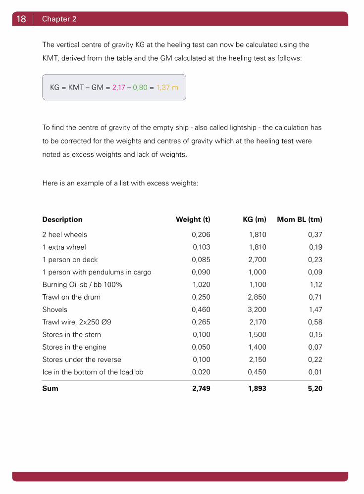
The vertical centre of gravity KG at the heeling test can now be calculated using the
KMT, derived from the table and the GM calculated at the heeling test as follows:
To find the centre of gravity of the empty ship - also called lightship - the calculation has
to be corrected for the weights and centres of gravity which at the heeling test were
noted as excess weights and lack of weights.
Here is an example of a list with excess weights:
Description
2 heel wheels
1 extra wheel
1 person on deck
1 person with pendulums in cargo
Burning Oil sb / bb 100%
Trawl on the drum
Shovels
Trawl wire, 2x250 Ø9
Stores in the stern
Stores in the engine
Stores under the reverse
Ice in the bottom of the load bb
Sum
Mom BL (tm)
0,37
0,19
0,23
0,09
1,12
0,71
1,47
0,58
0,15
0,07
0,22
0,01
5,20
KG (m)
1,810
1,810
2,700
1,000
1,100
2,850
3,200
2,170
1,500
1,400
2,150
0,450
1,893
Weight (t)
0,206
0,103
0,085
0,090
1,020
0,250
0,460
0,265
0,100
0,050
0,100
0,020
2,749
KG = KMT – GM = 2,17 – 0,80 = 1,37 m

19Determining a vessel’s stability
The list of missing weights may look like this:
Now the vessel’s lightweight is determined:
The vertical centre of gravity KG has the greatest impact on the vessel’s stability. The posi-tion of the longitudinal centre of gravity is also determined with the heeling test.
It can be approximately derived as the value of LCB in the same table where the KMT was previously read.
The vessel’s centre of buoyancy B and the vessel’s centre of gravity are always posi-tioned above each other. If G moves aft of the vessel, it will trim astern until the buoyancy centre is back below the centre of gravity G.
In order to find the longitudinal centre of gravity for lightship, the longitudinal centre of gravity from the heeling test also has to be corrected for the influence that excess weights and lack of weights have.
Description
Wheel house door
Outfitting materials in the wheelhouse
Sum
Mom BL (tm)
0,11
0,30
0,41
KG (m)
3,20
3,00
3,052
Weight (t)
0,035
0,100
0,135
Description
Ship in heeling conditioning
Excess
Missing
Lightweight
Mom BL (tm)
28,09
-5,20
0,30
23,30
KG (m)
1,370
1,893
3,052
1,303
Weight (t)
20,500
-2,749
0,135
17,886
20 Chapter 2
Calculating the vessel stabilityThe vessel’s lightweight data is the basis for all subsequent calculations of the vessel stability.
The calculations must certify that the vessel can operate safely and comply with all condi-tions under which the vessel is used. The Danish Maritime Authority has some standard conditions to be calculated, but it is the marine engineer’s task, in cooperation with the vessel’s skipper, to draw up any additional conditions to prove stability. For example this may be if the vessel carries out a different kind of fishing during part of the year, when the catch is loaded in the vessel in a different way.
For smaller vessels carrying out day fishing, how much catch / gear the vessel is permitted to carry on deck when the load is empty should also be calculated.
If the vessel uses different and / or heavier gear during the year, this has to be calculated separately.
This also applies if the vessel changes gear for different kinds of fishing such as industrial fishing for shorter periods of time.
All the calculations are gathered together in a stability report, which is often about 50 - 100 pages long. The report is submitted for approval to the Danish Maritime Authority by the marine engineer. The Danish Maritime Authority verifies that the material has been gone through properly and according to the requirements with respect to scope and content. An approved copy is then forwarded to the owner of the vessel to be kept on board the vessel.
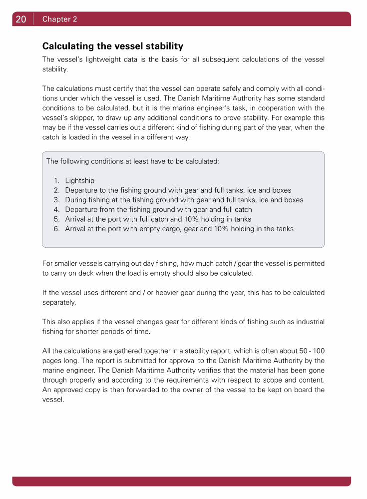
The following conditions at least have to be calculated:
1. Lightship 2. Departure to the fishing ground with gear and full tanks, ice and boxes3. During fishing at the fishing ground with gear and full tanks, ice and boxes4. Departure from the fishing ground with gear and full catch5. Arrival at the port with full catch and 10% holding in tanks6. Arrival at the port with empty cargo, gear and 10% holding in the tanks

21Determining a vessel’s stability
What are the rules?In order to assess whether a vessel has sufficient stability, the Danish Maritime Authority has a number of requirements, all of which have to be met. The GZ curve is used for this purpose.
The requirements ensure that the vessel has:
1. Sufficient beginning stability (stability at small heeling)2. Sufficient extent (stability at large heeling). For new vessels, the vessel must be
able to straighten up after heeling up to 65 degrees3. A peak where the heel must not be less than 25 degrees
In order to approve the vessel stability, the Danish Maritime Authority has listed a number of minimum requirements that must be met under all conditions.
There are required values for e.g.
• Areas under the GZ curve between a 0 – 30° heel 0 – 40° heel 30 – 40° heel• Minimum value for GM• Minimum value for GZ at 30° heel• The minimum permissible heeling angle at the peak of the curve
All requirements must be met before the report can be approved by the Danish Maritime Authority.
heeling

22 Chapter 2
What can the stability report be used for?At the end of the process that started with providing a line drawing / measuring the hull, carrying out the heeling test and collecting further data, the approved stability report is sent to the skipper.
Line drawing
Heeling test
Collecting data about the
use of the vessel STABILITY
REPORT
Approved by the DMA
Ok.In the “Guidlines for the
skipper“ in the first section of the stability report it says
how much fish I may load.
Measuring the hull

23
When the skipper gets his newly approved report, it is important to get an overview of the conditions in which the vessel is certified to operate and especially to establish what the limits are to how much the vessel can load. The main limits are summarized at the front of the stability report under “Guidelines for the skipper“.
Here by way of example is an extract from the “Guidelines for the skipper” of a small one-man trawler. The text provides some important guidelines on how much fish may be loaded, depending on where it is placed on board.
Determining a vessel’s stability
• When trawling, it must be en-
sured that the ship’s catch is
stowed securely and that a
maximum catch of 30 crates for
human consumption - equivalent
to 1.20 tonnes of fish - and 1.50
tonnes of fish on deck, totaling
2.70 tonnes of fish is not exceed-
ed and if necessary is limited
further. The maximum permis-
sible deadweight is 3.61 tonnes
with a freeboard amidships of
315 mm.
• When the hold is empty, the
maximum catch that may be
stored on deck is limited to 1.20
tonnes.
• When the hold is empty and
there is only catch in the hutch,
its weight must not exceed 0.55
tonnes.
24 Chapter 2
!
20
21
22
23
24
25
26
27
28
29
30
31
32
33
34
35
36
37
38
39
40
13 14 15 16 17 18 19 20 21 22 23
KG max*W (tm)
(6)
(2)
(3)
(4)
(5)
Allowed
Displacement (t)
(1)
(8)
Trim 0,40 m
Not allowed
Trim 0,00 m
(7)
(9)
(11)
(10)
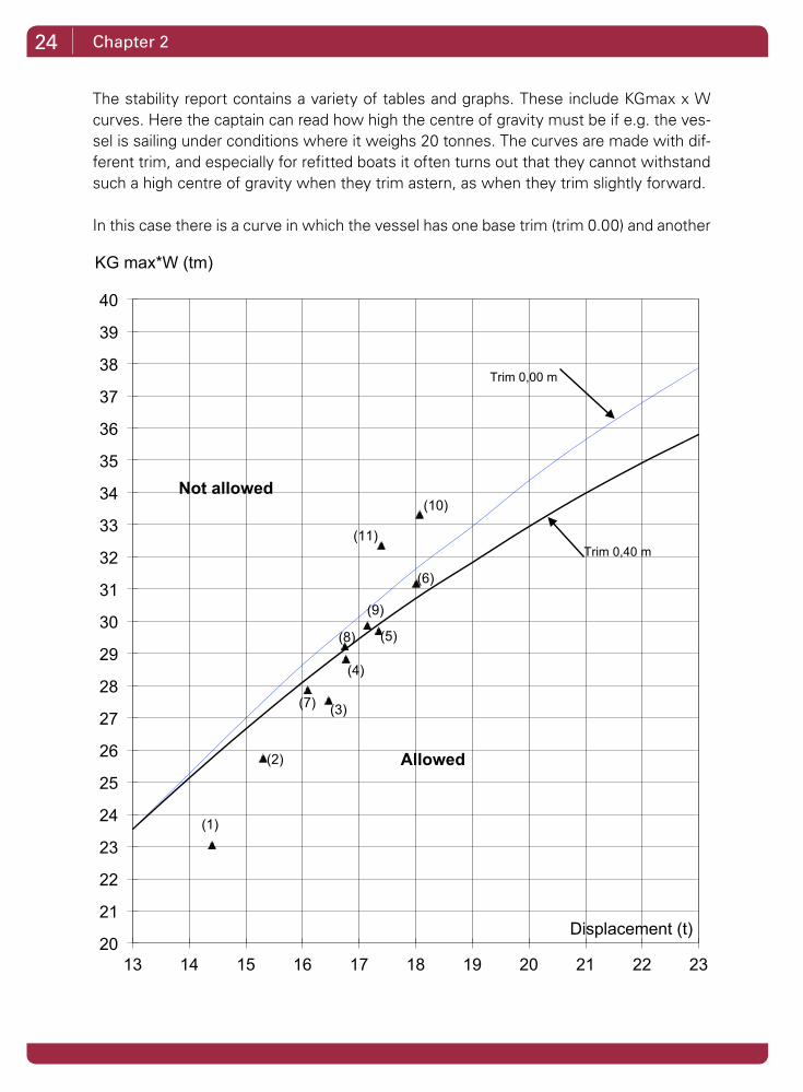
The stability report contains a variety of tables and graphs. These include KGmax x W curves. Here the captain can read how high the centre of gravity must be if e.g. the ves-sel is sailing under conditions where it weighs 20 tonnes. The curves are made with dif-ferent trim, and especially for refitted boats it often turns out that they cannot withstand such a high centre of gravity when they trim astern, as when they trim slightly forward.
In this case there is a curve in which the vessel has one base trim (trim 0.00) and another

25Determining a vessel’s stability
curve where the vessel trims 0.40 m astern.
When the vessel trims astern, the centre of gravity cannot be so high.
The diagram also includes the positions of the different conditions.
So in that way the skipper can quickly get an overview of those conditions that can be critical. The closer these conditions lie near the curve, the smaller the safety margin is.
The two conditions numbers 10 and 11 are up in the “Not permitted area”. These are to do with ice cover. These conditions are often carried out in order to inform the skipper.
The report also contains the necessary material in order for the skipper to be able to con-tact a ship’s engineer for a calculation of whether the vessel has sufficient stability for it to undergo a minor refit and/or replacement of the deck, drum, engine or other.
An approved report is no guarantee against disaster.
The skipper and crew must therefore constantly show diligence and good seaman-ship, taking into account the weather and sea, including the risk of icing, and take appropriate action.

26 Chapter 2
Dynamometer TestSo far, the Danish Maritime Authority has accepted that small fishing vessels dem-onstrate their stability by means of a dy-namometer test.
In a dynamometer test the vessel is heeled up to 40 degrees using a crane. The dy-namometer shows during the test how much the crane pulls to heel the vessel. Subsequently, an approximated GZ curve is plotted to determine whether the vessel has sufficient stability.
In a dynamometer test, the vessel is test-ed with gear, catch (or with compensation weights instead), fuel oil, etc., to find out how much the vessel max can load.
This test approximates the vessel’s stability in its current condition, but the vessel’s centre of gravity cannot be accurately determined. So a dynamometer test cannot form the basis for stability calculations for a later refit.
A large number of vessels under 10 metres were the last to perform a dynamometer test in the spring 2011. The Danish Maritime Authority no longer recognizes the dynamometer test for this class of vessels.
Dynamometer tests can still be used on open vessels.
In future, smaller deck vessels will have to take the same heeling tests as the larger vessels, and provide calculations and documentation in order to prove their stability.

27Determining a vessel’s stability
What about the very small vessels with a scantling number under 20?The smallest vessels are those which have a scantling number below 20.
The scantling number is determined as follows:
Recent tonnage certificates show the vessel’s scantling number.
Most open vessels have a scantling number below 20.
The Danish Maritime Authority does not normally require proof of stability for ves-sels with a scantling number below 20. But this does not exempt the vessel owner from the obligation to ensure that the vessel is seaworthy and has sufficient sta-bility.
Sufficient stability - also for the smallest vessels - comes from a combination of good sta-bility both at slight and large heeling.
Poor stability at small heeling reveals itself as soon as you step onto the gunwhale.
Poor stability at higher heeling is more difficult to assess, but a low freeboard should be considered as a warning of poor stability when heeling is more than 15-20 degrees.
Scantling number
Open vessels: maximum length x maximum width at the gunnel, minus fender = scantling number
Deck vessels: maximum length x maximum width of the deck measured on the out-side of the planking = scantling number
All measurements are in metres.
28 Chapter 2
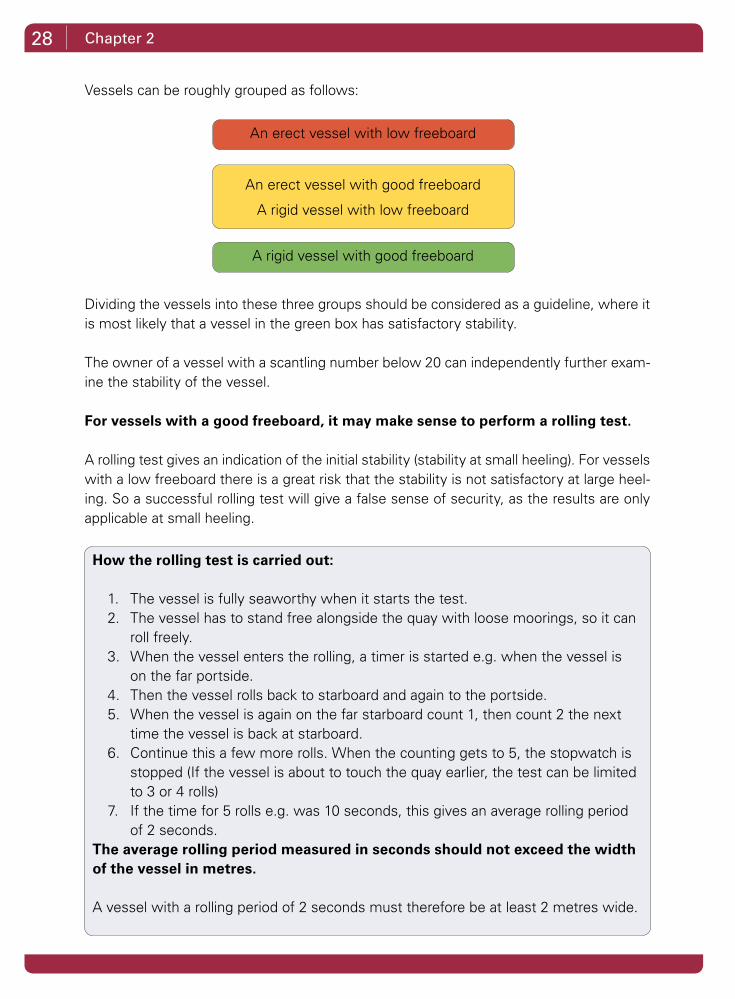
Vessels can be roughly grouped as follows:
Dividing the vessels into these three groups should be considered as a guideline, where it is most likely that a vessel in the green box has satisfactory stability.
The owner of a vessel with a scantling number below 20 can independently further exam-ine the stability of the vessel.
For vessels with a good freeboard, it may make sense to perform a rolling test.
A rolling test gives an indication of the initial stability (stability at small heeling). For vessels with a low freeboard there is a great risk that the stability is not satisfactory at large heel-ing. So a successful rolling test will give a false sense of security, as the results are only applicable at small heeling.
An erect vessel with low freeboard
An erect vessel with good freeboard
A rigid vessel with low freeboard
A rigid vessel with good freeboard
How the rolling test is carried out:
1. The vessel is fully seaworthy when it starts the test.2. The vessel has to stand free alongside the quay with loose moorings, so it can
roll freely.3. When the vessel enters the rolling, a timer is started e.g. when the vessel is
on the far portside.4. Then the vessel rolls back to starboard and again to the portside.5. When the vessel is again on the far starboard count 1, then count 2 the next
time the vessel is back at starboard.6. Continue this a few more rolls. When the counting gets to 5, the stopwatch is
stopped (If the vessel is about to touch the quay earlier, the test can be limited to 3 or 4 rolls)
7. If the time for 5 rolls e.g. was 10 seconds, this gives an average rolling period of 2 seconds.
The average rolling period measured in seconds should not exceed the width of the vessel in metres.
A vessel with a rolling period of 2 seconds must therefore be at least 2 metres wide.
29Determining a vessel’s stability
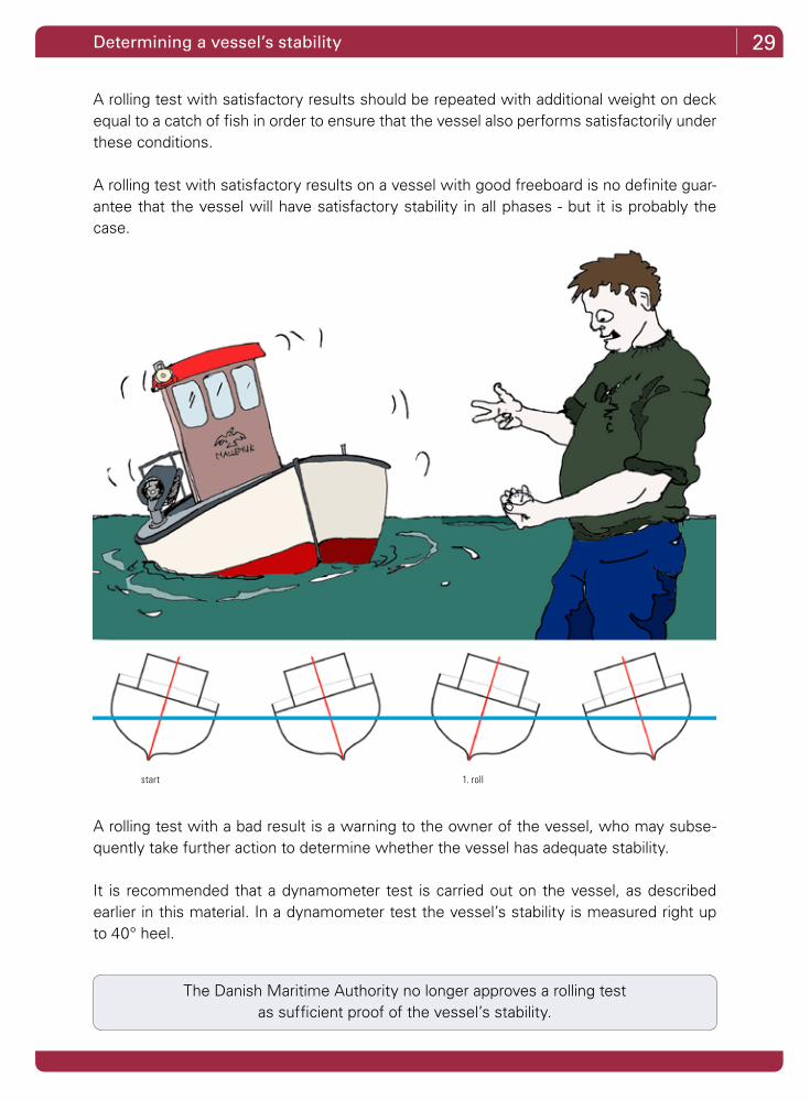
A rolling test with satisfactory results should be repeated with additional weight on deck equal to a catch of fish in order to ensure that the vessel also performs satisfactorily under these conditions.
A rolling test with satisfactory results on a vessel with good freeboard is no definite guar-antee that the vessel will have satisfactory stability in all phases - but it is probably the case.
A rolling test with a bad result is a warning to the owner of the vessel, who may subse-quently take further action to determine whether the vessel has adequate stability.
It is recommended that a dynamometer test is carried out on the vessel, as described earlier in this material. In a dynamometer test the vessel’s stability is measured right up to 40° heel.
The Danish Maritime Authority no longer approves a rolling test as sufficient proof of the vessel’s stability.
start 1. roll

30 Chapter 3
Measures to improve stabilityAfter the heeling test has been carried out, it often turns out that the resulting stability report will not meet the approval of the Danish Maritime Authority until one or more im-provements to the stability of the vessel have been made.
First it has to be clarified which of the stability requirements the vessel cannot meet.
For smaller deck vessels it is often the stability at larger heeling which causes problems. This is often caused by the fact that the vessel’s centre of gravity G is too high and the freeboard is too small.
The following material gives examples of what can be done to improve a vessel’s stability. Some of these examples can also be applied to a vessel with a scantling number below 20.
What can we do about it ?
The calculations show,
that the stability is not
sufficient...

31Measures to improve stability
FreeboardThe freeboard is the distance from the water surface to the top edge of the deck.
When a vessel has a low freeboard, its sheer plank will be under water already at small heeling.
When the sheer plank is submerged, there is no further volume to submerge at rising heel, thereby nothing that can further contribute to the buoyancy. The buoyancy centre B can move further out to the side to which the vessel is heeled.
When the buoyancy centre B cannot move further out at an increasing roll, the GZ achieves its maximum value at a low heel. The GZ value then begins to decline.
A vessel with a low freeboard can rarely be improved significantly by loading additional ballast. This vessel can be improved through different means that increase the vessel’s buoyancy.
Before additional bal-last is used, it is a good idea to check if there are other possibilities to reduce the vessel’s centre of gravity.
Vessels with low freeboard Vessel with reasonable freeboard
Vessel with high freeboard and high GZ value
Vessels with low freeboard and small GZ valueheeling
heeling
32 Chapter 3
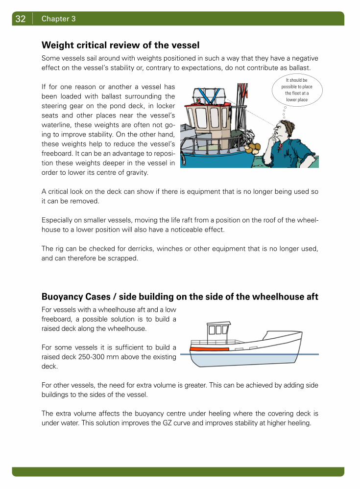
Weight critical review of the vesselSome vessels sail around with weights positioned in such a way that they have a negative effect on the vessel’s stability or, contrary to expectations, do not contribute as ballast.
If for one reason or another a vessel has been loaded with ballast surrounding the steering gear on the pond deck, in locker seats and other places near the vessel’s waterline, these weights are often not go-ing to improve stability. On the other hand, these weights help to reduce the vessel’s freeboard. It can be an advantage to reposi-tion these weights deeper in the vessel in order to lower its centre of gravity.
A critical look on the deck can show if there is equipment that is no longer being used so it can be removed.
Especially on smaller vessels, moving the life raft from a position on the roof of the wheel-house to a lower position will also have a noticeable effect.
The rig can be checked for derricks, winches or other equipment that is no longer used, and can therefore be scrapped.
Buoyancy Cases / side building on the side of the wheelhouse aftFor vessels with a wheelhouse aft and a low freeboard, a possible solution is to build a raised deck along the wheelhouse.
For some vessels it is sufficient to build a raised deck 250-300 mm above the existing deck.
For other vessels, the need for extra volume is greater. This can be achieved by adding side buildings to the sides of the vessel.
The extra volume affects the buoyancy centre under heeling where the covering deck is under water. This solution improves the GZ curve and improves stability at higher heeling.
It should be possible to place
the fleet at a lower place
33Measures to improve stability
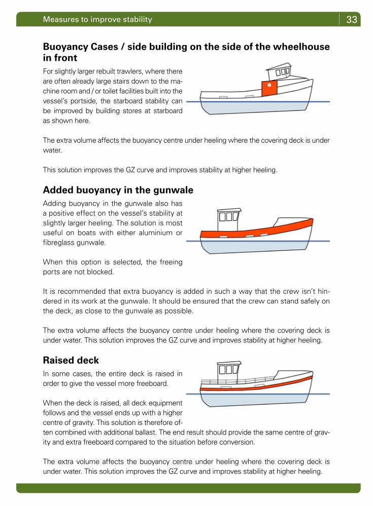
Buoyancy Cases / side building on the side of the wheelhouse in frontFor slightly larger rebuilt trawlers, where there are often already large stairs down to the ma-chine room and / or toilet facilities built into the vessel’s portside, the starboard stability can be improved by building stores at starboard as shown here.
The extra volume affects the buoyancy centre under heeling where the covering deck is under water.
This solution improves the GZ curve and improves stability at higher heeling.
Added buoyancy in the gunwale Adding buoyancy in the gunwale also has a positive effect on the vessel’s stability at slightly larger heeling. The solution is most useful on boats with either aluminium or fibreglass gunwale.
When this option is selected, the freeing ports are not blocked.
It is recommended that extra buoyancy is added in such a way that the crew isn’t hin-dered in its work at the gunwale. It should be ensured that the crew can stand safely on the deck, as close to the gunwale as possible.
The extra volume affects the buoyancy centre under heeling where the covering deck is under water. This solution improves the GZ curve and improves stability at higher heeling.
Raised deckIn some cases, the entire deck is raised in order to give the vessel more freeboard.
When the deck is raised, all deck equipment follows and the vessel ends up with a higher centre of gravity. This solution is therefore of-ten combined with additional ballast. The end result should provide the same centre of grav-ity and extra freeboard compared to the situation before conversion.
The extra volume affects the buoyancy centre under heeling where the covering deck is under water. This solution improves the GZ curve and improves stability at higher heeling.

34
Shelter deckA closed waterproof shelter deck is the ulti-mate way to improve the extent of the stabil-ity curve.
Some smaller trawlers that have been rebuilt can also benefit from a solution that creates a closed shelter from the rear edge of the wheelhouse to the forefront of the trawldrum on the rear.
A common feature of the preceding examples of stability-enhancing measures is that extra buoyancy is installed above the main deck. The buoyancy centre B can thus move further to the sides, improving the stability of the vessel at higher heeling.
This can be compared to the figures below:
On a vessel with low freeboard, B does not move very far. This corresponds to a rocking horse with short runners.
On a vessel with high freeboard / waterproof deckhouse, B can move further to the sides. This corresponds to a rocking horse with long runners which make it difficult to knock it over!
Chapter 3
35Measures to improve stability
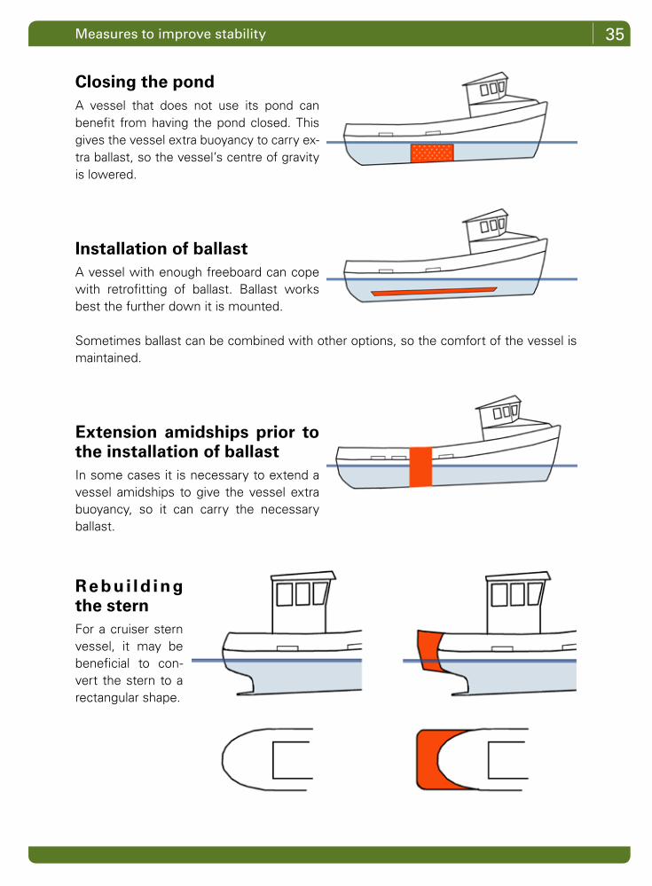
Closing the pondA vessel that does not use its pond can benefit from having the pond closed. This gives the vessel extra buoyancy to carry ex-tra ballast, so the vessel’s centre of gravity is lowered.
Installation of ballastA vessel with enough freeboard can cope with retrofitting of ballast. Ballast works best the further down it is mounted.
Sometimes ballast can be combined with other options, so the comfort of the vessel is maintained.
Extension amidships prior to the installation of ballastIn some cases it is necessary to extend a vessel amidships to give the vessel extra buoyancy, so it can carry the necessary ballast.
Re bui ld ing the sternFor a cruiser stern vessel, it may be beneficial to con-vert the stern to a rectangular shape.
36 Chapter 3
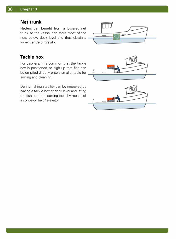
Net trunkNetters can benefit from a lowered net trunk so the vessel can store most of the nets below deck level and thus obtain a lower centre of gravity.
Tackle boxFor trawlers, it is common that the tackle box is positioned so high up that fish can be emptied directly onto a smaller table for sorting and cleaning.
During fishing stability can be improved by having a tackle box at deck level and lifting the fish up to the sorting table by means of a conveyor belt / elevator.
37Measures to improve stability
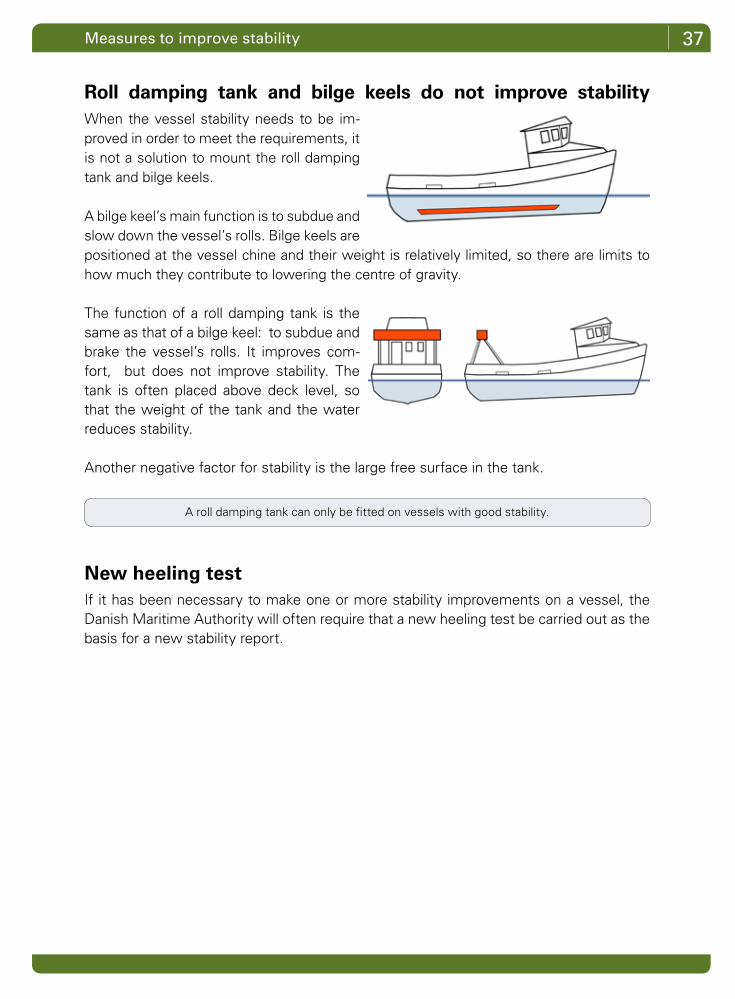
Roll damping tank and bilge keels do not improve stabilityWhen the vessel stability needs to be im-proved in order to meet the requirements, it is not a solution to mount the roll damping tank and bilge keels.
A bilge keel’s main function is to subdue and slow down the vessel’s rolls. Bilge keels are positioned at the vessel chine and their weight is relatively limited, so there are limits to how much they contribute to lowering the centre of gravity.
The function of a roll damping tank is the same as that of a bilge keel: to subdue and brake the vessel’s rolls. It improves com-fort, but does not improve stability. The tank is often placed above deck level, so that the weight of the tank and the water reduces stability.
Another negative factor for stability is the large free surface in the tank.
New heeling testIf it has been necessary to make one or more stability improvements on a vessel, the Danish Maritime Authority will often require that a new heeling test be carried out as the basis for a new stability report.
A roll damping tank can only be fitted on vessels with good stability.

38
What influences stabilityThe stability of the vessel is affected every time it is used. There are influences from deadweights such as catch, gear and fuel oil, but the stability is also affected by minor and major rebuilding of the vessel.
All these influences have an impact on the vessel’s freeboard and centre of gravity.
Is the vessel watertight?An important condition for adequate stability is a watertight vessel. Stability calculations assume that doors and hatches are closed.
Closed doors and hatches maintain the vessel’s stability.
When a door or hatch is open, there is free entry to the hull. Inflowing water rapidly re-duces the vessel’s stability, and there is imminent danger that the vessel will sink.
Chapter 4
heeling
heeling
39
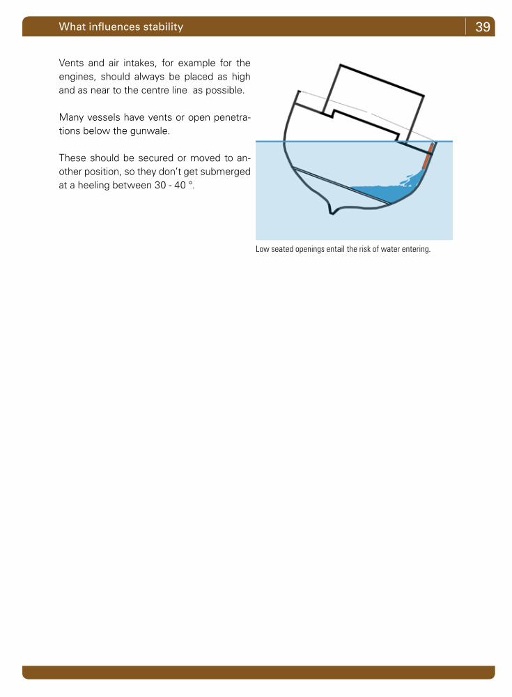
Vents and air intakes, for example for the engines, should always be placed as high and as near to the centre line as possible.
Many vessels have vents or open penetra-tions below the gunwale.
These should be secured or moved to an-other position, so they don’t get submerged at a heeling between 30 - 40 °.
What influences stability
Low seated openings entail the risk of water entering.
40 Chapter 4
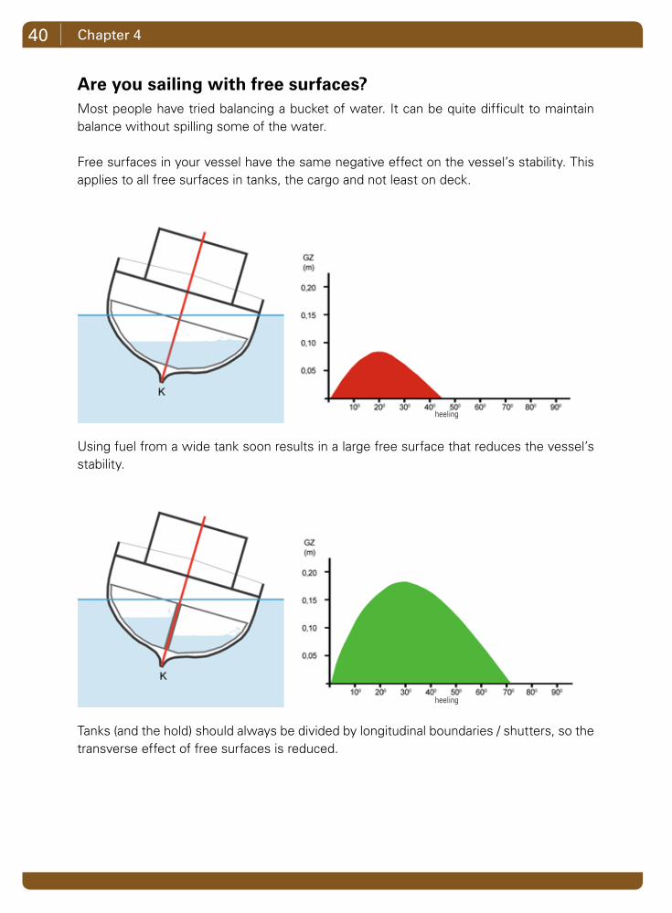
Are you sailing with free surfaces?Most people have tried balancing a bucket of water. It can be quite difficult to maintain balance without spilling some of the water.
Free surfaces in your vessel have the same negative effect on the vessel’s stability. This applies to all free surfaces in tanks, the cargo and not least on deck.
Using fuel from a wide tank soon results in a large free surface that reduces the vessel’s stability.
Tanks (and the hold) should always be divided by longitudinal boundaries / shutters, so the transverse effect of free surfaces is reduced.
heeling
heeling
41What influences stability
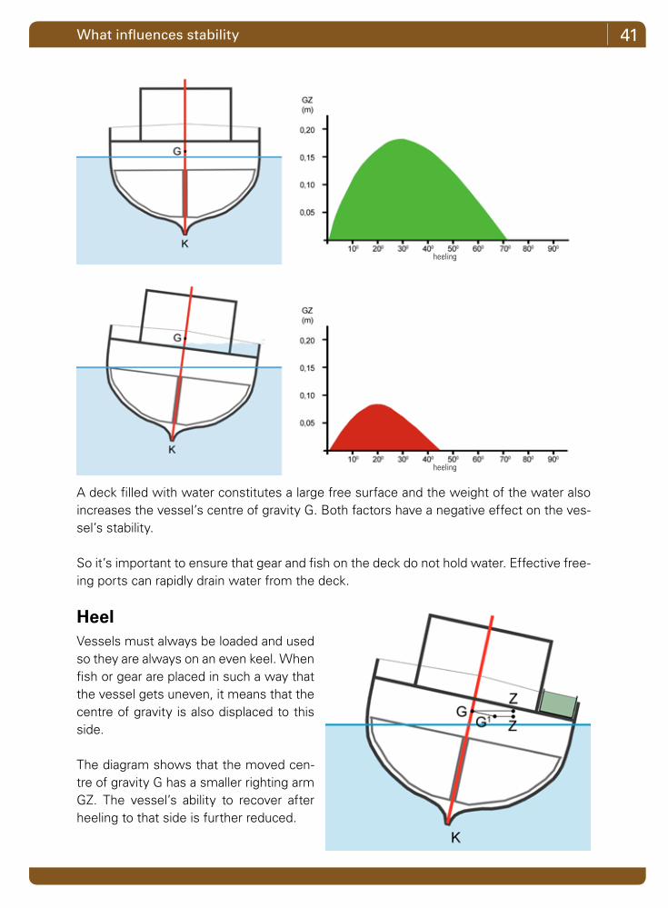
A deck filled with water constitutes a large free surface and the weight of the water also increases the vessel’s centre of gravity G. Both factors have a negative effect on the ves-sel’s stability.
So it’s important to ensure that gear and fish on the deck do not hold water. Effective free-ing ports can rapidly drain water from the deck.
HeelVessels must always be loaded and used so they are always on an even keel. When fish or gear are placed in such a way that the vessel gets uneven, it means that the centre of gravity is also displaced to this side.
The diagram shows that the moved cen-tre of gravity G has a smaller righting arm GZ. The vessel’s ability to recover after heeling to that side is further reduced.
heeling
heeling
42 Chapter 4
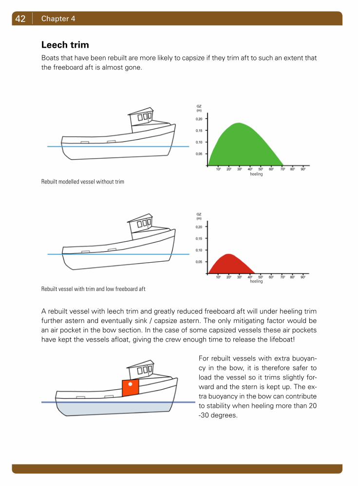
Leech trimBoats that have been rebuilt are more likely to capsize if they trim aft to such an extent that the freeboard aft is almost gone.
A rebuilt vessel with leech trim and greatly reduced freeboard aft will under heeling trim further astern and eventually sink / capsize astern. The only mitigating factor would be an air pocket in the bow section. In the case of some capsized vessels these air pockets have kept the vessels afloat, giving the crew enough time to release the lifeboat!
For rebuilt vessels with extra buoyan-cy in the bow, it is therefore safer to load the vessel so it trims slightly for-ward and the stern is kept up. The ex-tra buoyancy in the bow can contribute to stability when heeling more than 20 -30 degrees.
Rebuilt modelled vessel without trim
Rebuilt vessel with trim and low freeboard aft
heeling
heeling

43What influences stability
Hauling fish / liftingThe most critical moment for trawlers, seiners and dredgers is when the catch is lifted on board.
When the net is lowered on the deck, its centre of gravity is a short distance above the deck.
But until the net is landed on the deck (emptied), it hangs on the block, with its centre of gravity right up the block.
If a weight of 1 tonne is handled, this corresponds to a 1 tonne weight placed in the top of the boom. The vessel’s stability is signifi-cantly impaired at that mo-ment.
The most critical point is when the net is lifted out of the water. The ves-sel heels, and the entire weight of the lift works on the block at the top of the boom.
Approval of the vessel’s stability report does not cover the situation where the catch is lifted on board.
The size of the lift and the pulling force of the winch must therefore be adapted to the ves-sel’s stability, so there is no risk that the vessel can drag itself around in an attempt to lift an extra heavy haul.
If it is not possible to lift the catch in good time before the vessel reaches a heeling, where it has its optimal righting arm, the catch should be released.
heeling
heeling
heeling

44 Chapter 4
Towing with gear When trawling or towing with other fishing gear, the vessel’s stability is reduced. The higher the drag point and the heavier the drag, the more the stability is reduced.
When the vessel takes a turn with towed gear, the crew has to be very alert. If the vessel is forced into heeling and water presses through the freeing ports or over the gunwale, there is a risk that the vessel has reached a heeling beyond its maximum righting ability.
To push the vessel to an even larger heeling can therefore be fatal.
A vessel with good stability
When towing, the draft at the blocks raises the vessel’s centre of gravity and the vessel’s stability is reduced.
It is the skipper’s responsibility to know his vessel’s stability.It’s good seamanship not to push the vessel to its limits.
heeling
heeling

45What influences stability
Dirty nets on deckNetters in particular have to focus on the risk that comes from nets full of debris, so the weight of gear on deck is suddenly greater than normal.
If the vessel is loaded to the limit with clean nets, a load of dirty nets can prove critical, as the freeboard is reduced and the centre of gravity is increased.
Dirty nets on deck reduce the freeboard and the increase the centre of gravity
heeling
heeling
46 Chapter 4
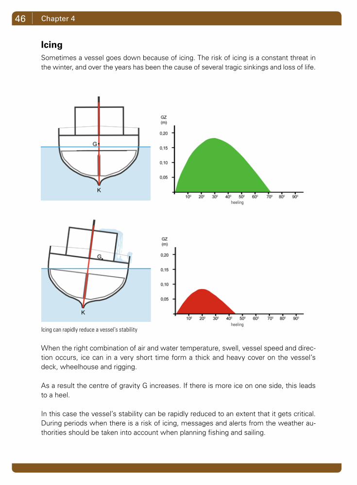
IcingSometimes a vessel goes down because of icing. The risk of icing is a constant threat in the winter, and over the years has been the cause of several tragic sinkings and loss of life.
When the right combination of air and water temperature, swell, vessel speed and direc-tion occurs, ice can in a very short time form a thick and heavy cover on the vessel’s deck, wheelhouse and rigging.
As a result the centre of gravity G increases. If there is more ice on one side, this leads to a heel.
In this case the vessel’s stability can be rapidly reduced to an extent that it gets critical. During periods when there is a risk of icing, messages and alerts from the weather au-thorities should be taken into account when planning fishing and sailing.
Icing can rapidly reduce a vessel’s stability
heeling
heeling
47What influences stability
When fishing in winter the vessel should be prepared accordingly by taking as much gear as possible below deck, so the deck is as clean and tidy as possible.
This reduces the surface where the ice can stick, and makes it easier to knock the ice loose and remove it from deck. Nets and net drums should be covered, for example with tarpaulin.
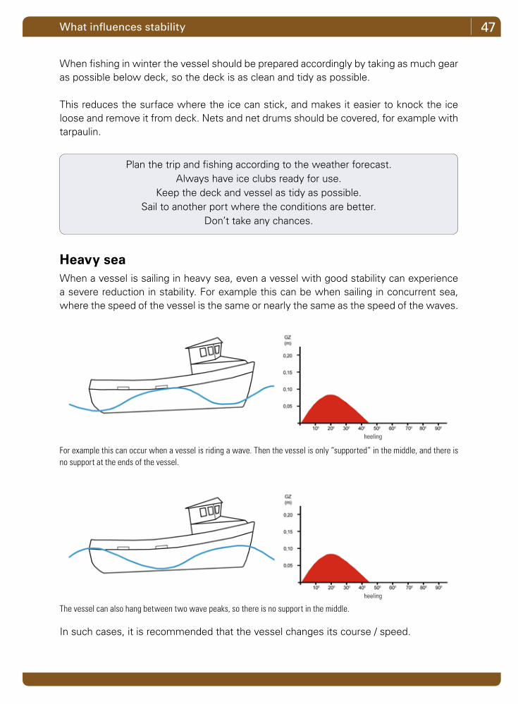
Heavy seaWhen a vessel is sailing in heavy sea, even a vessel with good stability can experience a severe reduction in stability. For example this can be when sailing in concurrent sea, where the speed of the vessel is the same or nearly the same as the speed of the waves.
In such cases, it is recommended that the vessel changes its course / speed.
Plan the trip and fishing according to the weather forecast.Always have ice clubs ready for use.
Keep the deck and vessel as tidy as possible.Sail to another port where the conditions are better.
Don’t take any chances.
For example this can occur when a vessel is riding a wave. Then the vessel is only “supported” in the middle, and there is no support at the ends of the vessel.
The vessel can also hang between two wave peaks, so there is no support in the middle.
heeling
heeling

48 Chapter 4
Small changes over timeOver the years, many vessels are continuously improved and modernized with new or additional equipment. When things happen slowly in small steps, they may seem unim-portant, but together they can significantly change the vessel’s stability - both in terms of reduced freeboard and changed centre of gravity.
For larger vessels over 15 metres, it has long been a requirement that they take a heeling test every 10 years to check whether the vessel’s lightweight and centre of gravity have remained the same. The purpose of this is just to check whether the small changes over time have affected stability.
For all dredgers and vessels under 15 metres, built after 2000, it is also required to take a heeling test every 10 years to control the vessel’s stability. All other vessels in this group only have to take a heeling test after being rebuilt.
The Danish Maritime Authority must be notified when a vessel has been rebuilt. Both the owner of the vessel and the company rebuilding the vessel must meet
this requirement.
Vessels change frequently over the years

49What influences stability
Routine check
To avoid a situation where a vessel slowly turns into an unstable one, several things can be done:
1. List all the deadweights removed from the vessel as well as all newly fitted equipment.
2. Take photos of the vessel, e.g. once a year, always from the same side. Com-pare the photos and focus on the changes. Use the photos to update the list mentioned under 1.
3. Measure the freeboard port and starboard with gear and filled fuel tanks. Measure the freeboard at the same place periodically and record the data. If this shows a decreasing freeboard, the vessel has got heavier over time.
4. Measure the vessel’s rolling period with gear and full tanks. Note the results and compare them with previous measurements. If the rolling periods are get-ting slower, this means that the centre of gravity is slowly increasing. In this case, contact the Danish Maritime Authority or marine engineer for an evalua-tion.
50
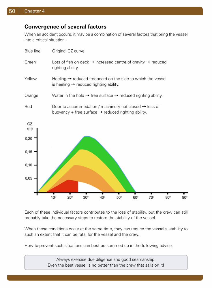
Convergence of several factorsWhen an accident occurs, it may be a combination of several factors that bring the vessel into a critical situation.
Blue line Original GZ curve
Green Lots of fish on deck → increased centre of gravity → reduced righting ability.
Yellow Heeling → reduced freeboard on the side to which the vessel is heeling → reduced righting ability.
Orange Water in the hold → free surface → reduced righting ability.
Red Door to accommodation / machinery not closed → loss of buoyancy + free surface → reduced righting ability.
Each of these individual factors contributes to the loss of stability, but the crew can still probably take the necessary steps to restore the stability of the vessel.
When these conditions occur at the same time, they can reduce the vessel’s stability to such an extent that it can be fatal for the vessel and the crew.
How to prevent such situations can best be summed up in the following advice:
Always exercise due diligence and good seamanship.Even the best vessel is no better than the crew that sails on it!
Chapter 4

51Terms and abbreviations
Terms and abbreviationsThe following list includes a brief explanation of many of the abbreviations and terms used in books on stability.
AP Aft perpendicular. Often defined as the centre of the rudder stock. All transverse dimensions are at a distance from AP
B Breadth. This is the maximum breadth measured at the outside of the planking. The breadth of deck vessels is measured at deck level. Open vessels are measured at the gunwale. The fender list is not included in the width.
B.mld Breadth moulded. The breadth of the vessel without planking.
BL Baseline. A horizontal line across the length of the vessel. All vertical dimensions and heights are measured from this line. The baseline is often defined so that it cuts 0X in the inner rabbet.
CL Centre line. Centre line between the vessel’s port and starboard side.
D Depth, also called side height, is the distance from the exterior rabbet to top deck in 0X.
Depl. Displacement. The vessel’s current weight. This equals the sum of lightweight and deadweight.
Dmld Depth moulded. This is the height measured from the inside rabbet to top deck beam
da Depth aft to bottom of the keel or to the lowered heel.
df Draught front. Draught of the lower edge of the keel.
FP Front perpendicular. Often defined as the bow cutting the designed waterline KWL.
FSM Free Surface Moment.
GM Metacentric height. The distance from the centre of gravity G to the metacentre M
GZ The righting arm. Expression of the vessel’s ability to get back on an even keel after heeling.

52 Terms and abbreviations
KB Distance from the keel K through the centre of buoyancy B. In practice, it is often the distance from BL to B. See also VCB.
KG Distance from the keel K through the centre of gravity G. In practice, it is often the distance from BL to G. See also VCG.
KM Distance from the keel K to the metacentre M. In practice it is often the distance from BL to M
KWL Designed waterline. Is always parallel to BL
LCB Longitudinal centre of buoyancy. In practice it is the distance from the centre of buoyancy B to AP
LCG Longitudinal centre of gravity. In practice it is the distance from the centre of gravity G to AP
LOA Length overall. The vessel’s maximum length. Not including fender list, trawlrolls, exterior rudders, etc.
Lpp Length between perpendiculars. That is the distance between AP and FP.
MCT Moment to change trim. This value that can be derived from hydrostatic tables. The value is used when calculating how much a vessel trims when a given weight is moved longitudinally.
Mom_BL Moment on the baseline. The sum of the moments of the individual weights on board can be divided by the boat’s displacement and the vessel’s total vertical center of gravity KG can be determined in exactly the condition.
0X Midship also called 0-junction. Defined as half the distance of Lpp. That is midway between AP and FP
Trim Also called structural trim or design trim. Fishing boats are often built with deeper draft aft. When the vessel is outside trim, that is with the same draft fore and aft to baseline, then the trim equals the difference in draft fore and aft.
VCB Vertical centre of buoyancy. The same explanation as for the Danish expression KB applies.
VCG Vertical centre of gravity. The same explanation as for the Danish expression KG applies.
W Deplacement. The current weight of the vessel. That is the sum of lightweight and deadweight


Auktionsgade 1b 6700 Esbjerg Denmark
Tel: +45 75 18 05 66 Fax: +45 75 18 05 75
[email protected] www.f-a.dk