stability analysis of a borehole wall during horizontal
TRANSCRIPT

Tunnelling and
www.elsevier.com/locate/tust
Tunnelling and Underground Space Technology 22 (2007) 620–632
Underground SpaceTechnologyincorporating Trenchless
Technology Research
Stability analysis of a borehole wall during horizontaldirectional drilling
X. Wang *, R.L. Sterling
Trenchless Technology Center, Louisiana Tech University, Ruston, LA 71272, United States
Available online 28 February 2007
Abstract
In this paper, numerical simulation strategies are proposed and numerical analyses are performed to investigate the stability of a bore-hole wall during horizontal directional drilling in loose sand with an emphasis on the role of the filter cake in borehole stability. Twocomputational scenarios, one in the absence of a filter cake and one with the presence of a filter cake in a borehole wall, are investigatedby considering both deep and shallow borehole situations. In the case where no filter cake is formed, the soil–drilling fluid interactionanalysis shows that the effective pressure on soil particles will quickly decrease to zero even at a low drilling fluid pressure because of therapid drainage of the drilling fluids into the loose sands. This conforms to the classical liquefaction criterion, indicating that static (flow)liquefaction-based soil crumbling and sloughing will occur even at a very low drilling fluid pressure if an effective filter cake is not formed.Soil’s permeability effect on pore pressure and the transition to a steady flow are also studied. In the second scenario in which a filter cakeis formed, the hydraulic fracture failures around the bores are investigated, which are caused by the expansion of the yielding zones. Theyield zone sizes and critical drilling fluid pressures at the moment of hydraulic fracturing failure are calculated from the finite elementanalyses and the closed-form solution, which is based on classical plasticity theories. The critical fluid pressures from the finite elementanalyses and the closed-form solutions are very close, but there is a large discrepancy between the yield zone sizes.Published by Elsevier Ltd.
Keywords: Stability analysis; Horizontal directional drilling; Finite element method; Filter cake; Soil and drilling fluid coupling; Critical drilling fluidpressure
1. Introduction
Horizontal directional drilling (HDD) is a trenchlessconstruction method typically used for the installation ofsmall-to-medium sized pipelines and conduits at relativelyshallow depths by using a surface-mounted rig (Bennettet al., 1995; Marshall et al., 2001). In the last 10 years, withthe improvement of HDD techniques, it has become a pop-ular and increasingly viable method for infrastructureinstallation in different areas within the construction indus-try, such as natural gas, electrical power and communica-tion industries (Chevron Chemical Co., LLC, 1999;Conroy et al., 2002; Latorre et al., 2002). In horizontal
0886-7798/$ - see front matter Published by Elsevier Ltd.
doi:10.1016/j.tust.2007.01.002
* Corresponding author. Tel.: +1 318 257 2934; fax: +1 318 257 2306.E-mail address: [email protected] (X. Wang).
directional drilling practice, the first step is to drill a guidedpilot hole along the bore path consisting of a shallow arcby mechanically cutting and mixing soil and/or rock for-mations with drilling fluids to form a flowable slurry. Inthe second or subsequent step(s), the bore is sufficientlyenlarged with larger diameter back reamer(s) before theproduct pipe is pulled into the bore and installed in the sub-surface (Ariaratnam and Lueke, 2002).
Despite its popularity and success, a number of issuesrelating to the HDD installation remain poorly under-stood. One of the important issues, concerning the applica-tion of HDD to very loose sand or gravel–sand mixtures,and presenting a big challenge to HDD industry, is howto effectively evaluate the stability of the borehole wall.Borehole collapse can lead to drill rods or pipes becomingstuck in the borehole and borehole fracture can result inthe release of drilling fluids from the borehole. To date,
X. Wang, R.L. Sterling / Tunnelling and Underground Space Technology 22 (2007) 620–632 621
some empirical equations based on the classical plasticitytheory are employed to calculate the critical fluid pressuresto prevent the borehole from collapse and hydraulic frac-ture in HDD practice (Staheli et al., 1998). It should alsobe noted that while borehole stability has been extensivelystudied in the petroleum exploration industry, the condi-tions under which borehole stability are investigated arevery different from the conditions for horizontal directionaldrilling. In the former, stability has been studied principallyin vertical boreholes at great depth in rock. In the latter,the stability of horizontal boreholes at relatively shallowdepths in loose soils is the issue.
In this paper, the borehole stability problem, from the col-lapse of granular soils near the borehole wall to the hydraulicfracturing induced by high drilling mud pressure, will bestudied using the finite element method. Unlike closed-formanalytical formulae that are based on the classic rigid-perfectplasticity theories or the empirical equations dependent onstatistical analyses for computations of the stresses nearthe horizontal borehole, the numerical model can easily inte-grate specific elasto-plastic constitutive descriptions (strainhardening and softening, and failure modes), inhomogenei-ties, and anisotropies of soils. The in-situ earth pressure willbe reasonably accounted for prior to the construction of thehorizontal directional drilling, and the sequential construc-tion procedures (excavation of the pilot hole and back ream-ing, etc.) will be incorporated in the elasto-plastic model toget realistic stress distributions. Elasto-plastic analyses ofthe filter cake and the soil mass will give the minimum andmaximum drilling fluid pressures to avoid the developmentof large plastic yield zones and the initiation of hydraulicfracturing or tensile rupture, which may eventually lead todrilling fluid circulation loss (Wang and Dusseault, 1991;Wang et al., 1994).
Using advanced simulation techniques, the importanceof creating a filter cake will be studied by coupling themechanics of the soil and drilling fluid interactions. The cri-terion for soil instability and soil sloughing will be associ-ated with the fluid behavior of loose sand, defined as soilliquefaction and commonly referred to as ‘‘quicksand’’(Hair, 1995a,b). The filter cake, which plays an importantrole in preventing borehole instability, involves the interac-tion between soil mass, flowing slurry, and ground water.
In this paper, an appropriate elasto-plastic soil constitu-tive model is used to reflect the soil deformation propertiesand failure modes. Static (flow) liquefaction, initiation anddevelopment of a plastic yielding zone, and the hydraulicfracture in the borehole wall are modeled to evaluate theborehole stability. The research is intended to develop anefficient numerical strategy to provide quantitative esti-mates for the safe range of drilling pressures for various siteconditions and borehole depths, and also to develop aquantitative understanding about the role of a filter cakein borehole stability. The research uses well-documentedsoil constitutive models and broadly accepted cutting-edgenumerical tools. This paper provides the results of someinitial simulations of the problem; an ongoing research
program is planned to further refine simulation techniquesand the understanding of the physical interactions occur-ring at the borehole wall.
2. A brief description of the theoretical bases of the analyses
Borehole stability requires a proper balance amongvarious soil parameters including: soil stress and strength,pore pressure, drilling fluid pressure and drilling mudchemical composition. Borehole instability is influencedby chemical effects (formation of a filter cake) andmechanical effects (soil sloughing and hydraulic fractur-ing). The finite element method is the fundamental toolto be used for the establishment of the analysis systemin this research. Existing analytical solutions for horizon-tal boreholes have been published and implemented insome design tools for industry application, which arebased on the classical rigid-perfect plasticity theories(Chevron Chemical Co., LLC, 1999; Conroy et al.,2002). Recently, numerical methods have also been usedto investigate borehole stability in HDD. Duyvestyn andKnight (2000) applied the finite difference method (com-mercial software FLAC) to predict soil deformationsdue to horizontal directional drilling pipeline installation.The finite element method presented in this paper pro-vides a state-of-the-art poro-mechanical approach toaccount for effects of coupled diffusion/deformation,which is governed by an equation that describes how totalstrains of the porous soil depend on the total appliedstresses and pore pressure weighted by Biot’s effectivestress parameter (Biot, 1956, 1977). In this parameter,the pore pressure is related to the pore fluid content var-iation, as well as the deformation of the porous body.Commercial finite element software ADINA (2001) isemployed to carry out the numerical analyses.
2.1. Constitutive modeling of the granular soil mass
In order to perform the borehole wall stability analysis,the granular soil deformation and strength behaviors suchas yielding, perfect plasticity, strain hardening and failuremodes involving the pressure-enhanced shear strength atdifferent loading conditions should be correctly character-ized in their constitutive descriptions (Desai and Christian,1977). In this paper, the Drucker–Prager model will beemployed. The corresponding material parameters will beobtained from the conventional triaxial compression orextension test data. Based on the elasto-perfectly plasticstress–strain relationship, the yield function of the Druc-ker–Prager model is written as follows (Chen and Mizuno,1990):
f ¼ aI1 þffiffiffiffiffiJ 2
p� j ¼ 0 ð1Þ
in which I1 and J2 represent the first stress invariant and thesecond deviatoric stress invariant, respectively. If the Druc-ker–Prager circle coincides with the outer apices of theMohr–Coulomb hexagon, we can have
622 X. Wang, R.L. Sterling / Tunnelling and Underground Space Technology 22 (2007) 620–632
a ¼ 2 sin /ffiffiffi3p
3� sin /ð Þ; j ¼ 6c cos /ffiffiffi
3p
3� sin /ð Þð2Þ
where / is the internal frictional angle. With / replaced bythe dilatational angle w for the associated flow rule, a plas-tic potential function can be established for the Drucker–Prager model.
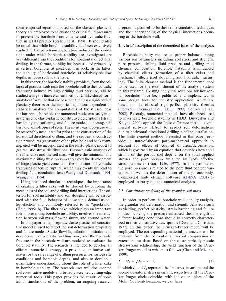
Fig. 1. Mesh discretization around the borehole: (a) before excavationand (b) after excavation.
2.2. The coupled analysis of drilling fluid and soil mass – a
generalized fluid–structure interaction model
During the drilling of a pilot hole and the subsequentback reamed hole, drilling fluids are normally injected inthe borehole to stabilize the bore, carry the fragmented soilwastes and lubricate the pipe and drill-string, etc. The dril-ling fluid, flowing through the annular space between thedrill rod or pipeline and the borehole wall, and seeping intothe borehole wall, interacts with the surrounding soil andground water, mechanically, thermally and chemically.The chemical and mechanical interaction between the dril-ling fluid and soil will give rise to the possible swift forma-tion of the so-called filter cake, which plays a crucial rolefor the borehole stability. The filter cake will prevent thedrilling fluid from seeping further into ground surroundingthe borehole wall. To make the interaction modeling sim-ple, the chemical interaction leading to the formation ofthe filter cake will be ignored here. The possible tempera-ture difference between the drilling fluid and the soil massis also neglected in this research. The effective stresses(pressure acting on soil particles, normal and shear stres-ses) change near the borehole because the mechanical inter-action will cause the soil mass near the borehole toexperience a decrease in its shear strength. If the residualstrength is low enough because of the increase in pore pres-sure, static (flow) liquefaction will occur in the soil, whichwill cause the soil to slough or crumble. Eventually, thehole will probably collapse. The analysis of unstable soilsloughing will provide the minimum drilling fluid pressureand the required properties of the filter cake to supportloose soil grains. If the drilling fluid pressure is too high,a large plastic yield zone and hydraulic fracturing willdevelop from the borehole boundary and propagate intothe deep borehole wall. This may eventually lead to col-lapse of the borehole wall and to drilling fluid circulationloss. In order to provide quantitative estimates for the saferange of drilling pressures, and also to gain a deeper under-standing of the role of the filter cake in providing boreholestability, numerical analyses of two scenarios are per-formed. In the first scenario, where an effective filter cakeis not formed, drilling fluids will keep seeping into a soilmass, which has high permeability. For this scenario, afully coupled analysis of the soil medium and drilling fluidswill be considered. In the poro-mechanical model used, dis-placement is an independent variable at each nodal point,and pore fluid pressure is the second independent variableat each corner nodal point (Wang and Dong, 2003). In thesecond scenario, a filter cake is formed before the drilling
fluids flow extensively into the borehole wall and the filtercake is assumed to prevent the further seepage of the dril-ling fluids during the drilling period. For this scenario, apure elasto-plastic analysis without coupling is performed.
3. Scenarios of the numerical simulations
In order to obtain a precise and useful solution, the flowof drilling fluid through the drill pipe annulus should beconsidered. Based on the recent development of computa-tional mechanics, the drilling flow through the annularspace can be modeled in connection with the pore flowthrough the bore wall (Bathe et al., 1999; Zhang et al.,2003). Two 2-D analyses are performed, one covers the lon-gitudinal sectional area of the borehole, and the other oneis for the cross-sectional area of the borehole.
Results presented in this paper, however, are only forthe simplified case where the drilling fluid behavior is sim-ulated by applying a fluid pressure on the cross-sectionalboundary of the borehole wall. The interaction is only con-sidered between the pore flow and the porous wall medium.
A conceptual solution procedure is given in this section,which is based on the foregoing framework. An entire com-putational work is completed in several steps, from whichcritical drilling fluid pressures are obtained: the lower crit-ical pressure under which soils near a borehole will crumbleand which may lead to the collapse of the borehole wall;and an upper critical pressure which induces the inceptionand propagation of plastic yield zones and hydraulic frac-tures eventually. In all of the following analyses to be per-formed, gel strengths of the drilling fluid are assumed largeenough to suspend drilled spoil when the fluid is at rest.
The cross-section of a half bore is taken for analysisbecause of symmetry, as shown in Fig. 1. In the deep boresituation, for demonstration purposes, the borehole isassumed drilled through a very loose natural levee at thedepth of 30.48 m with a diameter of 38.1 cm. In the shallowbore situation, a borehole of the same size is drilledthrough the same soil at the depth of 6.10 m. Mechanicalproperties of the soil (including the filter cake) are givenin Table 1. It should be noted that since the associated flow

Table 1Soil material properties
Modulus ofelasticity(MPa)
Poisson’sratio
Frictionalangle (�)
Cohesion(kPa)
Density(kg/m3)
Soil 69.0 0.35 20 69 1474Filter
cake138.0 0.35 25 138 1474
X. Wang, R.L. Sterling / Tunnelling and Underground Space Technology 22 (2007) 620–632 623
rule is used, it is assumed that the angle of dilation is theangle of friction.
The soil mass above the borehole will be meshed all theway up to the ground surface as shown in Figs. 1 and 2.The soil mass is horizontally 12 times as large as the boreradius. The distance from the bottom of the bore to thebottom of the soil mass is 20 times as large as the boreradius. The left and right sides of the soil mass are bothpinned horizontally and free for vertical movement, andthe bottom boundary is fixed in two directions. The gravityof the soil mass is applied as a body force.
4. Numerical solutions
As described in Section 2, numerical analyses will beperformed in two scenarios. Scenario 1: A filter cake isnot formed before drilling fluids seep deeply into the bore-hole wall. In this scenario, a fully two-phase poro-elasto-plastic coupled analysis will be undertaken. Scenario 2: Afilter cake is formed with much lower permeability and
Fig. 2. Mesh discretization of the soil mass around the borehole.
higher material strength and modulus of elasticity. In thiscase, the drilling fluid is assumed not to seep into the bore-hole wall. Only an elasto-plastic analysis is carried out forthe soil mass around the borehole. In all the stress solutionsshown below, a geotechnical stress sign convention isemployed in which compression takes a positive sign andtension a negative sign. However, in the pore pressure dis-tribution plots, positive sign represents tension and nega-tive sign for compression. The analyses for the twoscenarios are performed, respectively.
4.1. Scenario one: no filter cake
In the cases of both deep and shallow borehole situa-tions, the soil domains are discretized using a total of1520 plane strain quadrilateral 9-node solid elements forthe discretized domain. Soils through the whole domainare assumed homogeneous. Analyses are conducted forthe boreholes at two different overburden depths, whichcorrespond to the drilling fluid pressures on the boreholeboundary given in Table 2 (deep hole situation) and Table3 (shallow hole situation). They remain constant through-out the analyses. Permeability of the soil is identical inthe X, Y and Z directions. In this research, two permeabil-ities, 4.45e�11 Pa m2/s and 4.45e�6 Pa m2/s, are taken forthe soils, respectively. Excess pore pressure is assumed zeroon the boundaries of the soil mass except the boreholeperimeter where pore pressure is equal to the drilling fluidpressure. All the solutions presented, such as excess porepressures and pressures between soil particles near the
Table 2aMinimum soil pressure at the bore crown at the specified drilling fluidpressures (deep hole case, permeability k = 4.45e�11 Pa m2/s)
Drilling fluidpressure (kPa)
165.5 172.4 179.3 186.2 193.1 196.5
Soil pressure (kPa)Initial 5.68 1.14 �3.43 �8.01 �12.60 �14.90Steady 15.60 11.60 7.54 3.52 0.53 �2.56
Table 2bMinimum soil pressure at the bore crown at the specified drilling fluidpressures (deep bore case, permeability k = 4.45e�6 Pa m2/s)
Drilling fluidpressure (kPa)
172.4 179.3 186.2 193.1 200.0 206.9
Soil pressure (kPa)Initial 12.20 8.14 4.13 0 �4.08 �8.15Steady 11.50 7.49 3.47 �0.57 �4.62 �8.68
Table 3aMinimum soil pressure at the bore crown at the specified drilling fluidpressures (shallow bore case, permeability k = 4.45e�11 Pa m2/s)
Drilling fluid pressure (kPa) 27.6 34.5 44.1 88.3Soil pressure (kPa)
Initial 4.66 �0.06 �6.8 �36.90Steady 6.46 2.19 �3.80 �31.20

-20
-15
-10
-5
0
5
10
15
20
160 165 170 175 180 185 190 195 200
Drilling fluid pressure (kPa)
So
il p
ress
ure
(kP
a) Initial state
Stedy state
Fig. 3. Drilling fluid pressure versus the minimum soil pressure at thecrown (deep bore, permeability k = 4.45e�11 m2 Pa/s).
Table 3bMinimum soil pressure at the bore crown at the specified drilling fluidpressures (shallow bore case, permeability k = 4.45e�6 Pa m2/s)
Drilling fluid pressure (kPa) 27.6 34.5 44.1 88.3Soil pressure (kPa)
Initial 6.61 2.38 �3.55 �30.70Steady 6.62 2.38 �3.55 �30.70
-10
-5
0
5
10
15
170 175 180 185 190 195 200 205
Drilling fluid pressure (kPa)
So
il p
ress
ure
(kP
a) Initial state
Steady state
Fig. 4. Drilling fluid pressure versus minimum soil pressure at theborehole crown area (deep bore, permeability k = 4.45e�6 Pa m2/s).
Fig. 5. Initial pore pressure (a) and steady pore pressure (b) distributionspermeability k = 4.45e�11 Pa m2/s).
624 X. Wang, R.L. Sterling / Tunnelling and Underground Space Technology 22 (2007) 620–632
borehole boundary, are time dependent. Increase in porepressure will decrease the effective stress around the bore-hole. As a result, it will lead to the reduction of soilstrength. Flow liquefaction will be likely to occur in thearea. For the sake of simplicity, flow liquefaction is charac-terized here by the classical liquefaction criterion that thereduction to zero effective stress by induced pore pressureimplies the occurrence of liquefaction (Morgenstern,1994). In this paper, the flow liquefaction is considered toinitiate from where the effective soil pressure reduces tozero.
The pore pressures on all the boundaries are time inde-pendent. But they are time dependent at any point withinthe borehole wall domain. For the deep bore case with adepth of 30.48 m, Tables 2a and 2b give the minimum soilpressure values at the bore crowns when the soil permeabil-ity is 4.45e�11 Pa m2/s and 4.45e�6 Pa m2/s, respectively. Ifthe soil has a low permeability, the minimum soil pressureacts on the bore crown immediately after the seepage starts.Then, it will be getting larger and larger before the steadydrilling fluid flow is reached. If the soil takes a permeabilityof 4.45e�6 Pa m2/s, Tables 2b and 3b imply that a steadyflow in the bore wall is reached very quickly. Under thecondition of lower permeability, Fig. 3 also shows the rela-tionship between the drilling fluid pressure and the mini-mum soil pressure at the bore crown area for the lowerpermeability situation. It presents nearly a zero soil pres-sure as soon as the drilling fluid pressure reaches174 kPa, and the soil pressure will stay at zero after asteady drilling fluid flow is formed at a drilling fluid pres-sure of 193 kPa. It implies that static soil liquefaction islikely to occur after the drilling fluid pressure arrives at174 kPa. When the soil permeability takes a value of4.45e�6 Pa m2/s, Fig. 4 shows that the critical drilling fluidpressure will rise to 194 kPa. In the shallow bore case withan overburden depth of 6.1 m, Figs. 9 and 10 give critical
around the borehole (deep bore, drilling fluid pressure p0 = 179.4 kPa,

Fig. 6. Initial pore pressure (a) and steady pore pressure (b) distributions around the borehole (deep bore, drilling fluid pressure p0 = 193.1 kPa,permeability k = 4.45e�6 Pa m2/s).
Fig. 7. Soil pressure distribution at the initial flow condition (a) and at the steady flow condition (b) (deep bore, p0 = 179.4 kPa, permeabilityk = 4.45e�11 Pa m2/s).
X. Wang, R.L. Sterling / Tunnelling and Underground Space Technology 22 (2007) 620–632 625
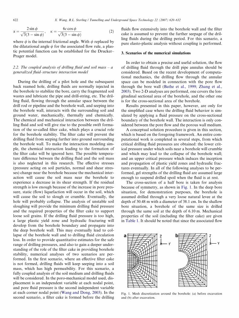
drilling fluid pressures of 33 kPa and 39 kPa for low perme-ability and high permeability situations, respectively. Rep-resentative initial and steady pore pressure distributionsaround the borehole are given in Figs. 5 and 6 for the deepbore case, and Figs. 11 and 12 for the shallow bore case,respectively. They have shown again that soils with highpermeability will have high critical drilling fluid pressureagainst a static liquefaction-based soil problem like soilcrumbling or sloughing. When the permeability increasesfrom 4.45e�11 Pa m2/s to 4.45e�6 Pa m2/s, the steady flowcondition will be approached shortly after the bore isdrilled. The soil pressure distributions with the initial andsteady flow conditions in the same local areas are presentedin Figs. 7 and 8 for the deep bore case. Figs. 13 and 14show the soil pressure distributions for the shallow bore
case. The pore pressure and the soil pressure solutions inthis research strongly suggest that a filter cake plays anessential role in maintaining bore wall stability. Flow lique-faction-induced soil crumbling, which may result in the col-lapse of a borehole, is more likely to occur if no filter cakeforms around the borehole boundary immediately after thedrilling penetration in loose sand.
4.2. Scenario two: existence of a filter cake
With an effective physio-chemical interaction betweenthe drilling fluid and soil, a filter cake may form as quicklyas the drilling fluid seeps into the bore wall. A stiffer filtercake, with a much lower permeability and higher shearstrength, will prevent the drilling fluids from seeping fur-

Fig. 8. Soil pressure distributions at the initial flow condition (a) and at the steady flow condition (b) (deep bore, p0 = 193.1 kPa, permeabilityk = 4.45e�6 Pa m2/s).
626 X. Wang, R.L. Sterling / Tunnelling and Underground Space Technology 22 (2007) 620–632
ther into the borehole wall. In the corresponding analysisfor a limited period of horizontal drilling time, an assump-tion can be made that no significant seepage effect occursbehind the filter cake. The soil and filter cake are also bothmodeled using the Drucker–Prager yield criterion with thesame or different mechanical properties, as listed in Table 1for both cases with drilled holes at different depths. Thesame domain and mesh discretization as used in the firstscenario will be applied to the computations at this stage.Based on the research work done by Arends (2003), the fil-ter cake is assumed 2.54 cm thick.
At this stage, the drilling fluid pressure will be graduallyincreased, as shown in Table 4 for the deep bore situationand Table 5 for the shallow bore situation, respectively.The occurrence and growth of plastic yielding indicatethe inception and propagation of the hydraulic fracturingzone in the wall.
In the case of the deep bore, band plots of yield functionvalues are given in Fig. 15, which correspond to the six dif-ferent drilling fluid pressures. The dark areas around theborehole represent the plastic yield zones.
-40
-35
-30
-25
-20
-15
-10
-5
0
5
10
0 20 40 60 80 100
Drilling fluid pressure (kPa)
So
il p
ress
ure
(kP
a)
Initial state
Steady state
Fig. 9. Drilling fluid pressure versus minimum soil pressure on the borecrown (shallow bore, permeability k = 4.45e�11 Pa m2/s).
Before the drilling fluid pressure is applied, a plasticyield zone has appeared near the springline of the bore-hole. With an increase in the drilling fluid pressure, theplastic yield zone diminishes. From Fig. 15a, it can be seenthat the plastic yield zone dramatically dwindles as thedrilling fluid pressure reaches 0.48 MPa, which is nearlyequal to the overburden pressure, but new plastic yieldzones have developed at the crown and invert areas ofthe borehole. Nevertheless, the plastic yield zones staythe smallest if the drilling fluid pressure is equal to theoverburden earth pressure. With the increase in the dril-ling fluid pressure, the plastic yield zones expand moreand more significantly, as shown in Fig. 15, where red col-ored yield zones are plotted at different drilling fluid pres-sures. As the drilling fluid pressure rises to 3.0 MPa, whichis around 6.8 times the overburden earth pressure, a broadplastic zone around the borehole has been developed atthe crown and invert areas of the borehole wall. The plas-tic zone is from the crown to the invert, with its radiusapproximately three times as large as the borehole radius.The fracture failure occurs around the borewall because ofthe extremely large yield zone at the drilling fluid pressureof 3.0 MPa.
-40
-30
-20
-10
0
10
0 20 40 60 80 100
Drilling fluid pressure (kPa)
So
il p
ress
ure
(kP
a)
Initial state
Steady state
Fig. 10. Drilling fluid pressure versus minimum soil pressure on the borecrown (shallow bore, permeability k = 4.45e�6 Pa m2/s).

Fig. 11. Pore pressure distribution (shallow bore, p0 = 34.5 kPa, permeability k = 4.45e�11 Pa m2/s) (a) at the initial stage and (b) at the steady flowcondition.
Fig. 12. Pore pressure distribution (shallow bore, p0 = 34.5 kPa, permeability k = 4.45e�6 Pa m2/s) (a) at the initial stage and (b) at the steady flowcondition.
X. Wang, R.L. Sterling / Tunnelling and Underground Space Technology 22 (2007) 620–632 627
An analytical equation provided by Staheli et al. (1998)is available to estimate the maximum allowable drillingfluid pressure. The equation is based on the classic perfectplasticity theory, and the maximum allowable drilling fluidpressure reads
pmax ¼ uþ p0max
¼ uþ ðp0f þ c � cot /Þ � R0
Rp;max
� �2
þ Q
( ) � sin /1þsin /ð Þ
� c � cot / ð3Þ
In which u is the initial pore pressure that is taken as zeroin this research. p0max is the maximum allowable effectivemud pressure. p0f is the drilling mud pressure at which thefirst plastic deformation takes place. It is derived basedon the rigid plastic theories:
p0f ¼ r00 � 1þ sin /ð Þ þ c � cos / ð4Þ
r00 is the initial effective soil stress at the center of the bore-hole. / is the internal frictional angle. c is the soil cohesion.R0 indicates the initial radius of the borehole. Rp, max signi-fies the radius of the plastic zone. Q, another mechanicalparameter, can be obtained using
Q ¼ r00 � sin /þ c � cos /=G ð5Þ
In Eq. (5), G represents the shear modulus. In Eqs. (3)–(5),stress and stress-like variables are measured in N/mm2, andlengths are measured in millimeters. According to Conroyet al. (2002), Rp, max has a value of two thirds of the heightof the soil cover over the borehole. Substituting in theabove three equations all the necessary parameters we haveused for the finite element analyses, an empirical maximumdrilling mud pressure of 2.67 MPa is obtained, in contrast
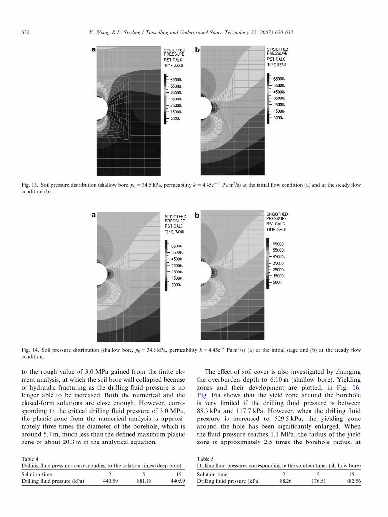
Fig. 13. Soil pressure distribution (shallow bore, p0 = 34.5 kPa, permeability k = 4.45e�11 Pa m2/s) at the initial flow condition (a) and at the steady flowcondition (b).
Fig. 14. Soil pressure distribution (shallow bore, p0 = 34.5 kPa, permeability k = 4.45e�6 Pa m2/s) (a) at the initial stage and (b) at the steady flowcondition.
628 X. Wang, R.L. Sterling / Tunnelling and Underground Space Technology 22 (2007) 620–632
to the rough value of 3.0 MPa gained from the finite ele-ment analysis, at which the soil bore wall collapsed becauseof hydraulic fracturing as the drilling fluid pressure is nolonger able to be increased. Both the numerical and theclosed-form solutions are close enough. However, corre-sponding to the critical drilling fluid pressure of 3.0 MPa,the plastic zone from the numerical analysis is approxi-mately three times the diameter of the borehole, which isaround 5.7 m, much less than the defined maximum plasticzone of about 20.3 m in the analytical equation.
Table 4Drilling fluid pressures corresponding to the solution times (deep bore)
Solution time 2 5 15Drilling fluid pressure (kPa) 440.59 881.18 4405.9
The effect of soil cover is also investigated by changingthe overburden depth to 6.10 m (shallow bore). Yieldingzones and their development are plotted, in Fig. 16.Fig. 16a shows that the yield zone around the boreholeis very limited if the drilling fluid pressure is between88.3 kPa and 117.7 kPa. However, when the drilling fluidpressure is increased to 529.5 kPa, the yielding zonearound the hole has been significantly enlarged. Whenthe fluid pressure reaches 1.1 MPa, the radius of the yieldzone is approximately 2.5 times the borehole radius, at
Table 5Drilling fluid pressures corresponding to the solution times (shallow bore)
Solution time 2 5 15Drilling fluid pressure (kPa) 88.26 176.51 882.56

Fig. 15. Yield zones (red colored) corresponding to different drilling fluid pressures (deep bore) (a) 0.48 MPa, (b) 0.73 MPa, (c) 1.2 MPa, (d) 1.94 MPa (e)2.64 MPa and (f) 3.0 MPa. (For interpretation of the references in color in this figure legend, the reader is referred to the web version of this article.)
X. Wang, R.L. Sterling / Tunnelling and Underground Space Technology 22 (2007) 620–632 629
which the hydraulic fracture failure occurs. The criticaldrilling fluid pressure from the analytical equation is cal-culated as 1.19 MPa, still very close to the numericalsolution.
From all the presented solutions, some preliminary con-clusions may be made. Even though a filter cake may beformed, a drilling fluid pressure maintained at a certainlevel is necessary to prevent the collapse of a borehole in

Fig. 16. Yield zones (red colored) around the borehole corresponding to different drilling fluid pressures (deep bore) (a) 88.26 kPa, (b) 117.68 kPa,(c) 147.09 kPa, (d) 176.51 kPa (e) 529.54 kPa, (f) 1.01 MPa, (g) 1.06 MPa and (h) 1.10 MPa. (For interpretation of the references in color in this figurelegend, the reader is referred to the web version of this article.)
630 X. Wang, R.L. Sterling / Tunnelling and Underground Space Technology 22 (2007) 620–632
loose sands. A drilling fluid pressure at the initial earthpressure level of the soil mass appears to be the optimumchoice to maintain borehole stability. Large fluid pressuresmay also lead to borehole collapse due to the expansion ofthe plastic yielding zone, namely so-called hydraulic frac-turing in horizontal directional drilling. To obtain accuratenumerical solutions, more efforts should be devoted to
investigating the thickness and material properties of thefilter cake.
5. Concluding remarks
The stability of a borehole in horizontal directional dril-ling has been studied in this paper with a particular focus